Exo-planètes, étoiles et galaxies : progrès de l'observation · • Le diamètre du "Direct...
36
• Fichiers des cours précédents sur: www.college-de-france.fr/default/EN/all/ast_obs/annee_20082009.htm • Articles sur: www.oamp.fr/lise Exo-planètes, étoiles et galaxies : progrès de l'observation
Transcript of Exo-planètes, étoiles et galaxies : progrès de l'observation · • Le diamètre du "Direct...
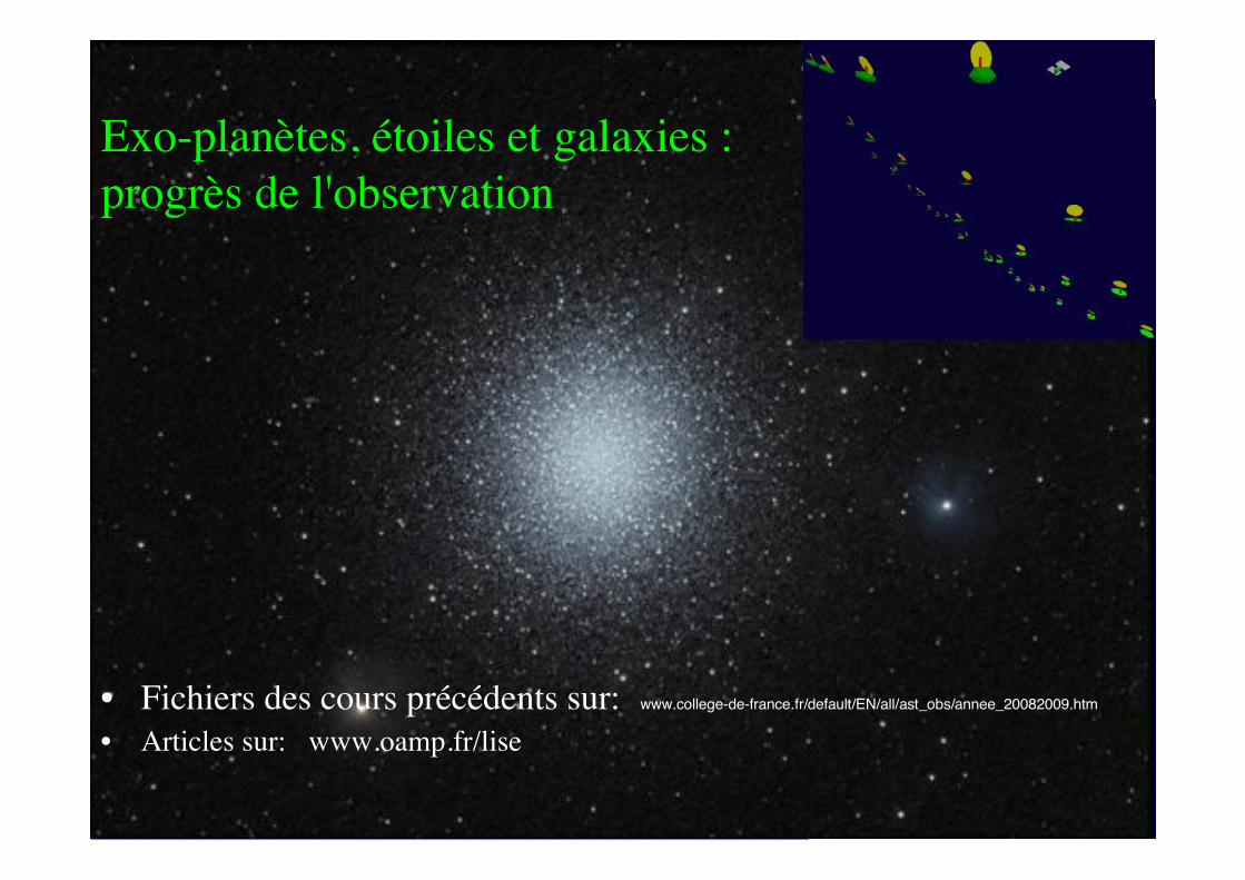
• Fichiers des cours précédents sur: www.college-de-france.fr/default/EN/all/ast_obs/annee_20082009.htm
• Articles sur: www.oamp.fr/lise
Exo-planètes, étoiles et galaxies :
progrès de l'observation
• 10 Mars
Cours 4: Hypertélescope spatial à miroirs piégés par laser
Séminaire: Pascal Petit " L'activité magnétique des jumeaux solaires"
• 17 Mars
Cours 5: Hypertélescope spatial à miroirs piégés par laser (suite)
Séminaire: Stéphane Jacquemoud "La végétation comme signe de vie extraterrestre : espoirs etobstacles"
• 24 Mars
Cours 6: Hypertélescope spatial à miroirs piégés par laser (suite)
Séminaire:
• 1er -2 Avril: cours et séminaires à Grenoble, détails sur http://www.ujf-grenoble.fr/74905189/0/fiche___pagelibre/
Exo-planètes, étoiles et galaxies : progrès de l'observation
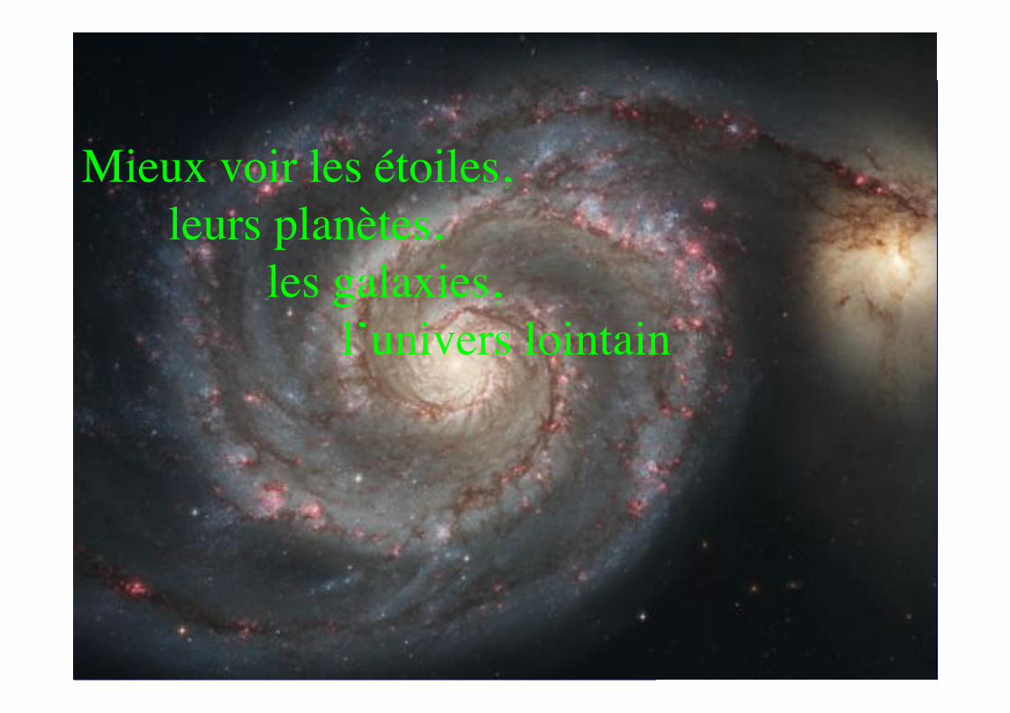
Mieux voir les étoiles,
leurs planètes,
les galaxies,
l’univers lointain
Séminaire à 15h :
Pascal Petit ( Observatoire Midi Pyrénées )!
"L'activité magnétique des jumeaux solaires "
!
Aujourd'hui:
Hypertélescope spatial à miroirs piégés par laser
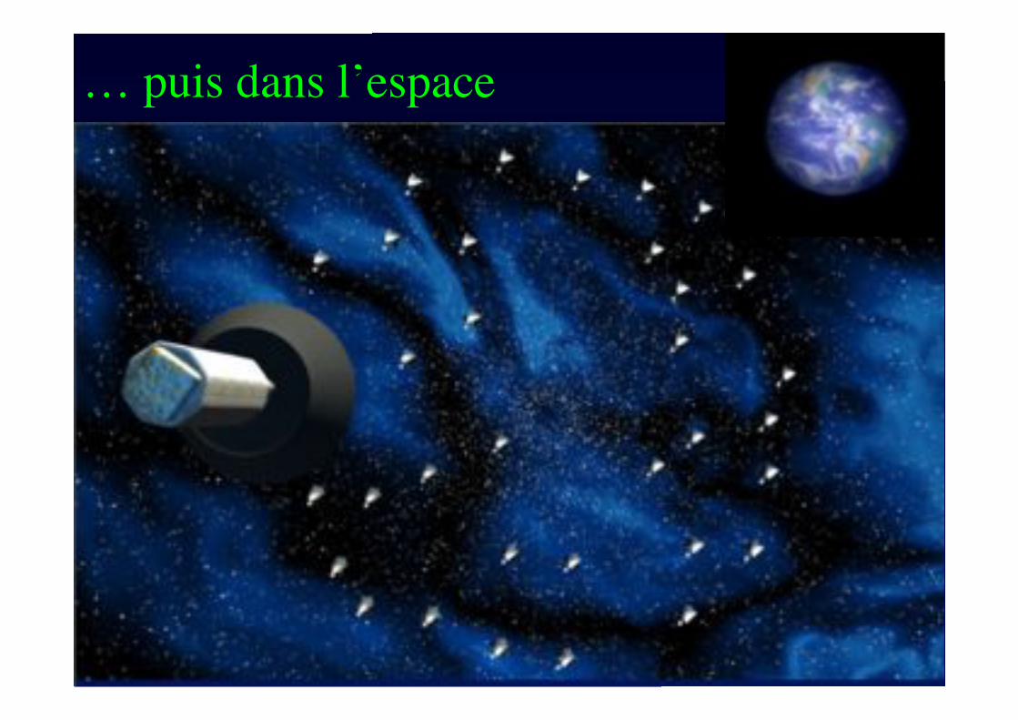
… puis dans l’espace
Signatures de vie extra-
solaire
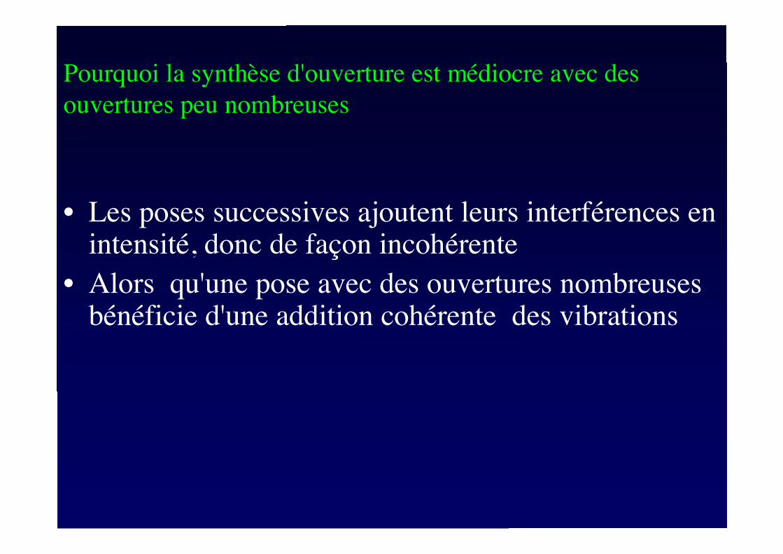
• Les poses successives ajoutent leurs interférences enintensité, donc de façon incohérente
• Alors qu'une pose avec des ouvertures nombreusesbénéficie d'une addition cohérente !des vibrations
!
Pourquoi la synthèse d'ouverture est médiocre avec des
ouvertures peu nombreuses
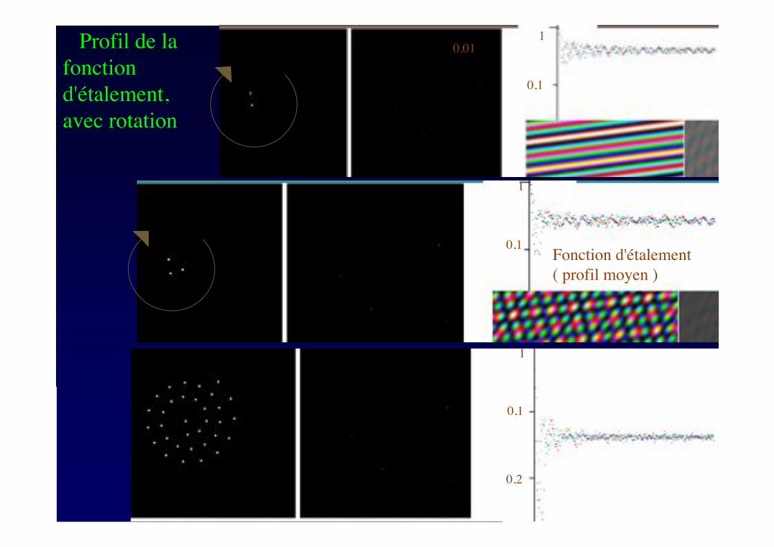
Profil de la
fonction
d'étalement,
avec rotation
0,1
0,011
Fonction d'étalement
( profil moyen )
0,1
1
1
0,1
0,2
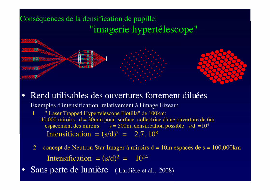
Conséquences de la densification de pupille:
"imagerie hypertélescope"
• Rend utilisables des ouvertures fortement diluéesExemples d'intensification, relativement à l'image Fizeau:
1 " Laser Trapped Hypertelescope Flotilla" de 100km:40,000 miroirs, d = 30mm pour surface collectrice d'une ouverture de 6m
espacement des miroirs: s = 500m, densification possible s/d =104
Intensification = (s/d)2 = 2,7. 108
2 concept de Neutron Star Imager à miroirs d = 10m espacés de s = 100,000km
Intensification = (s/d)2 = 1014
• Sans perte de lumière ( Lardière et al., 2008)
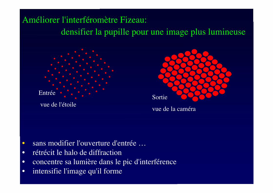
Améliorer l'interféromètre Fizeau:
densifier la pupille pour une image plus lumineuse
• sans modifier l'ouverture d'entrée …
• rétrécit le halo de diffraction
• concentre sa lumière dans le pic d'interférence
• intensifie l'image qu'il forme
Entrée
vue de l'étoile
Sortie
vue de la caméra
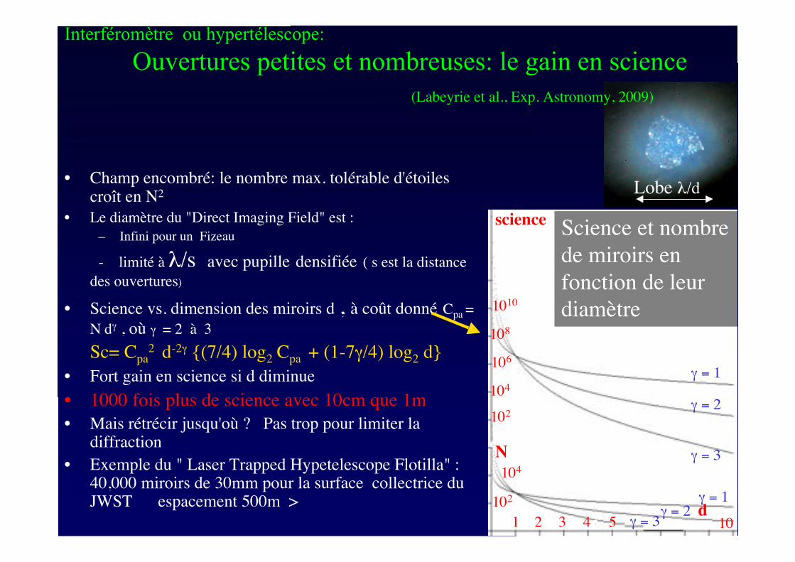
• Champ encombré: le nombre max. tolérable d'étoilescroît en N2
• Le diamètre du "Direct Imaging Field" est :
– Infini pour un Fizeau
- limité à !/s avec pupille densifiée ( s est la distance
des ouvertures)
• Science vs. dimension des miroirs d , à coût donné Cpa =
N d" , où " = 2 à 3
Sc= Cpa2 d-2" {(7/4) log2 Cpa + (1-7"/4) log2 d}
• Fort gain en science si d diminue
• 1000 fois plus de science avec 10cm que 1m
• Mais rétrécir jusqu'où ? Pas trop pour limiter ladiffraction
• Exemple du " Laser Trapped Hypetelescope Flotilla" :40,000 miroirs de 30mm pour la surface collectrice duJWST espacement 500m >
Lobe !/d
Interféromètre ou hypertélescope:
Ouvertures petites et nombreuses: le gain en science
(Labeyrie et al., Exp. Astronomy, 2009)
10
104
1010
102
102
science
106
108
1
104
N
" = 32 3 4 5
" = 2
" = 3
" = 1
" = 2" = 3
" = 1d
10
Science et nombre
de miroirs en
fonction de leur
diamètre
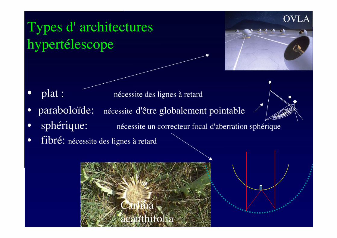
Types d' architectures
hypertélescope
• plat : nécessite des lignes à retard
• paraboloïde: nécessite d'être globalement pointable
• sphérique: nécessite un correcteur focal d'aberration sphérique
• fibré: nécessite des lignes à retard
OVLA
Carlina
acanthifolia
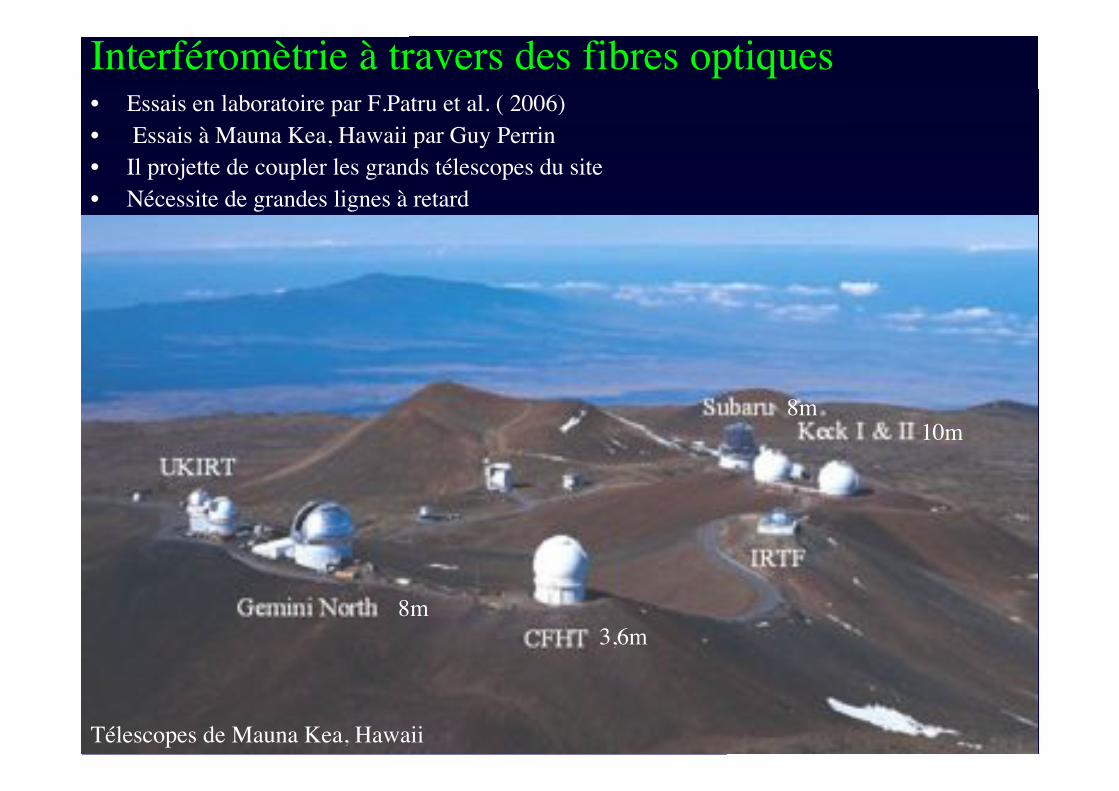
Interféromètrie à travers des fibres optiques• Essais en laboratoire par F.Patru et al. ( 2006)
• Essais à Mauna Kea, Hawaii par Guy Perrin
• Il projette de coupler les grands télescopes du site
• Nécessite de grandes lignes à retard
Télescopes de Mauna Kea, Hawaii
3,6m
8m
8m10m
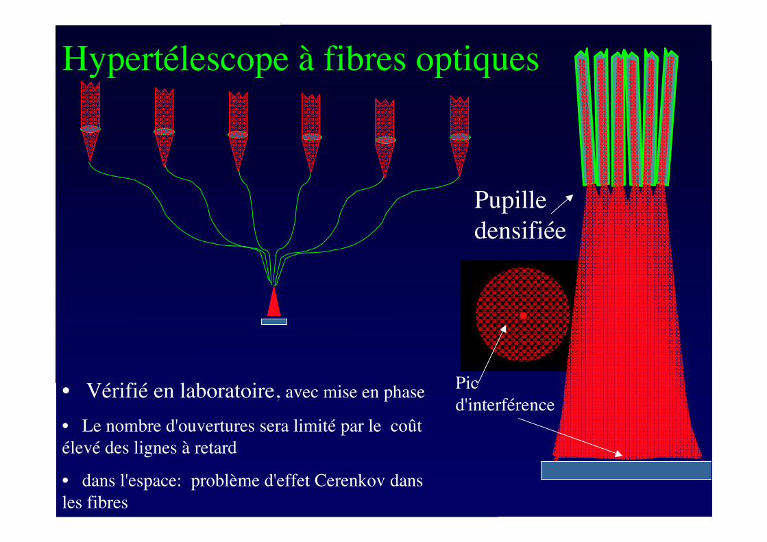
Hypertélescope à fibres optiques
• Vérifié en laboratoire, avec mise en phase
• Le nombre d'ouvertures sera limité par le coût
élevé des lignes à retard
• dans l'espace: problème d'effet Cerenkov dans
les fibres
Pupille
densifiée
Pic
d'interférence
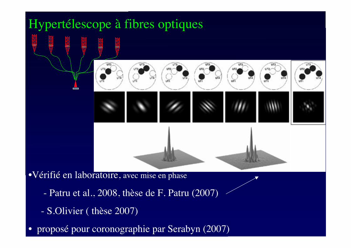
Hypertélescope à fibres optiques
•Vérifié en laboratoire, avec mise en phase
- Patru et al., 2008, thèse de F. Patru (2007)
- S.Olivier ( thèse 2007)
• proposé pour coronographie par Serabyn (2007)
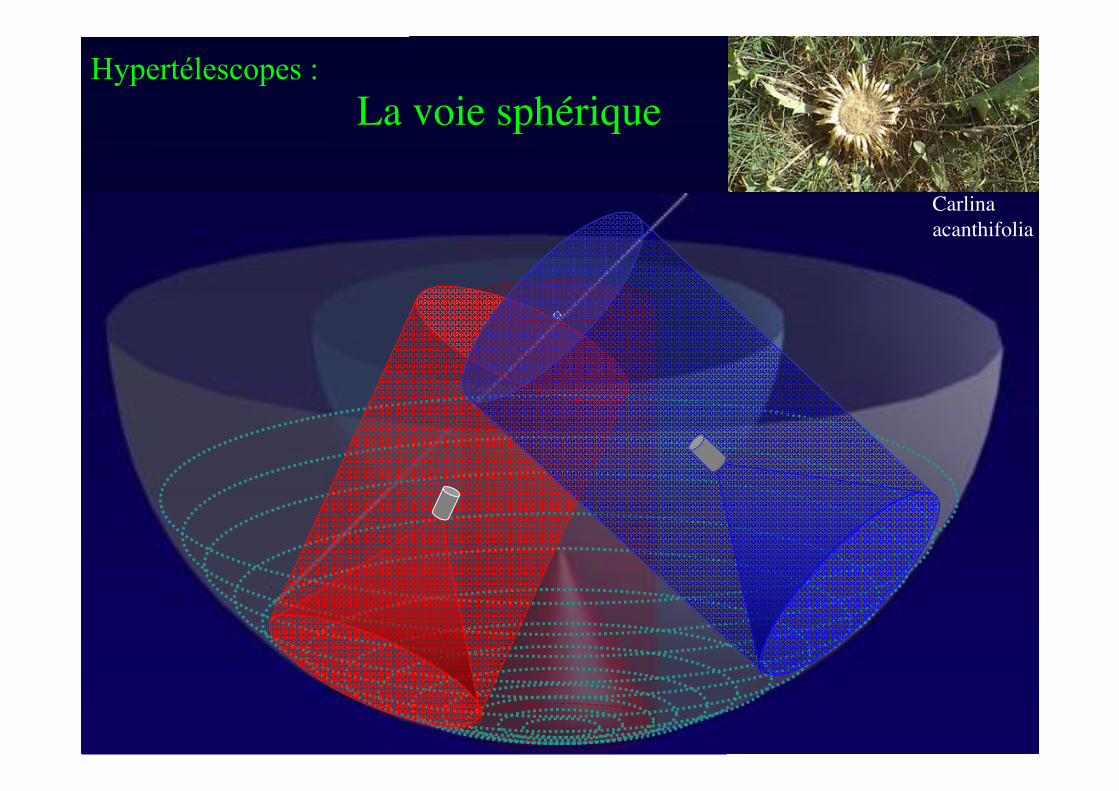
Hypertélescopes :
La voie sphérique
Carlina
acanthifolia
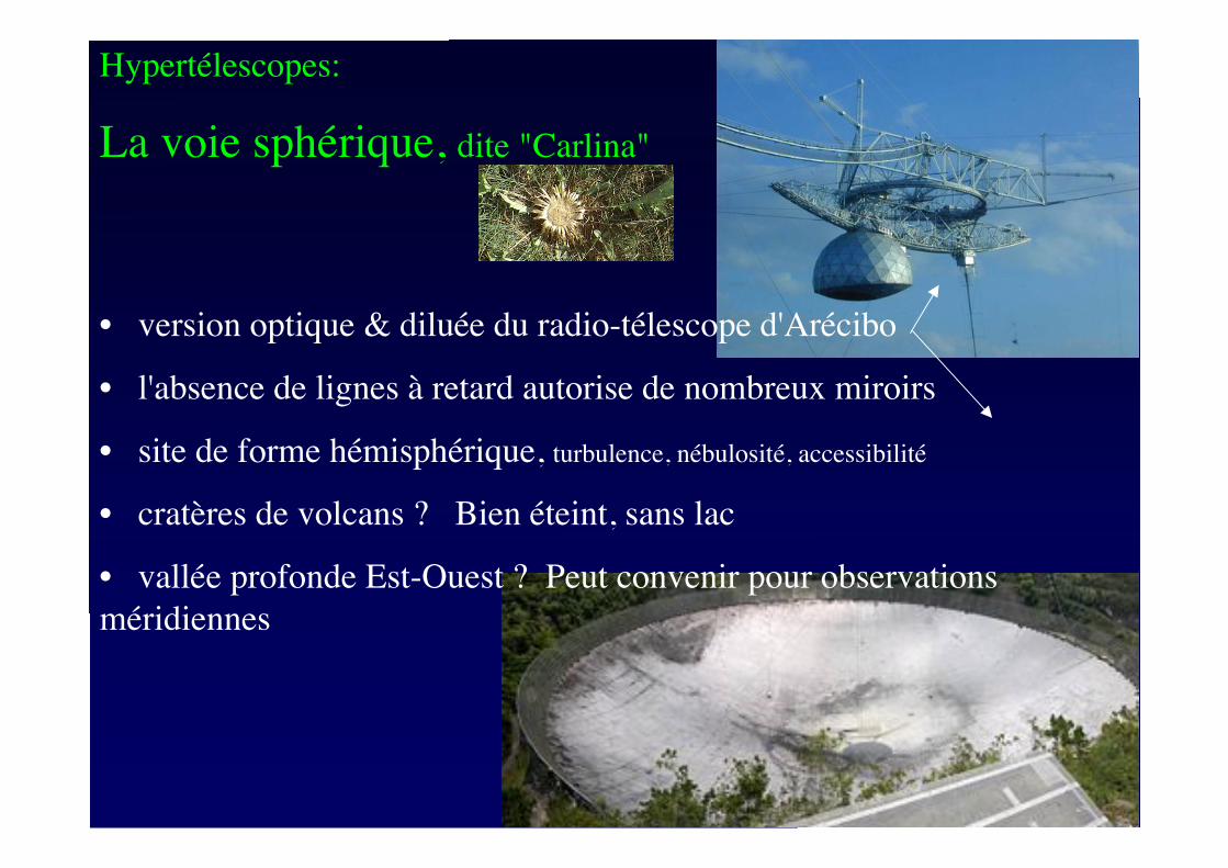
Hypertélescopes:
La voie sphérique, dite "Carlina"
• version optique & diluée du radio-télescope d'Arécibo
• l'absence de lignes à retard autorise de nombreux miroirs
• site de forme hémisphérique, turbulence, nébulosité, accessibilité
• cratères de volcans ? Bien éteint, sans lac
• vallée profonde Est-Ouest ? Peut convenir pour observations
méridiennes
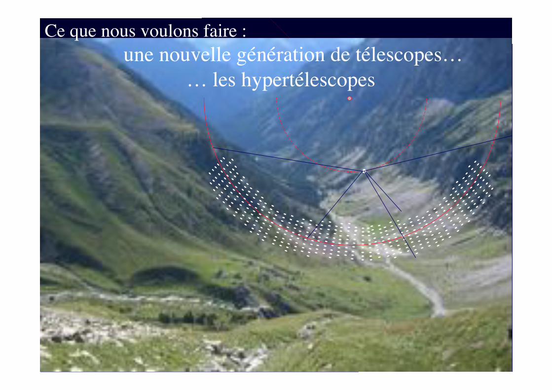
Ce que nous voulons faire :
une nouvelle génération de télescopes…
… les hypertélescopes
Prototype with balloon-borne
camera at Haute Provence
observatory
200m aperture version under
study
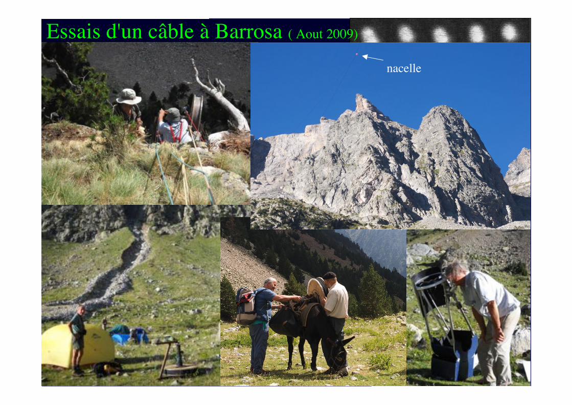
Cable suspension tested in the
Spanish Pyreneees
Essais d'un câble à Barrosa ( Aout 2009)
Fringes (Le Coroller et al., 2005)
nacelle
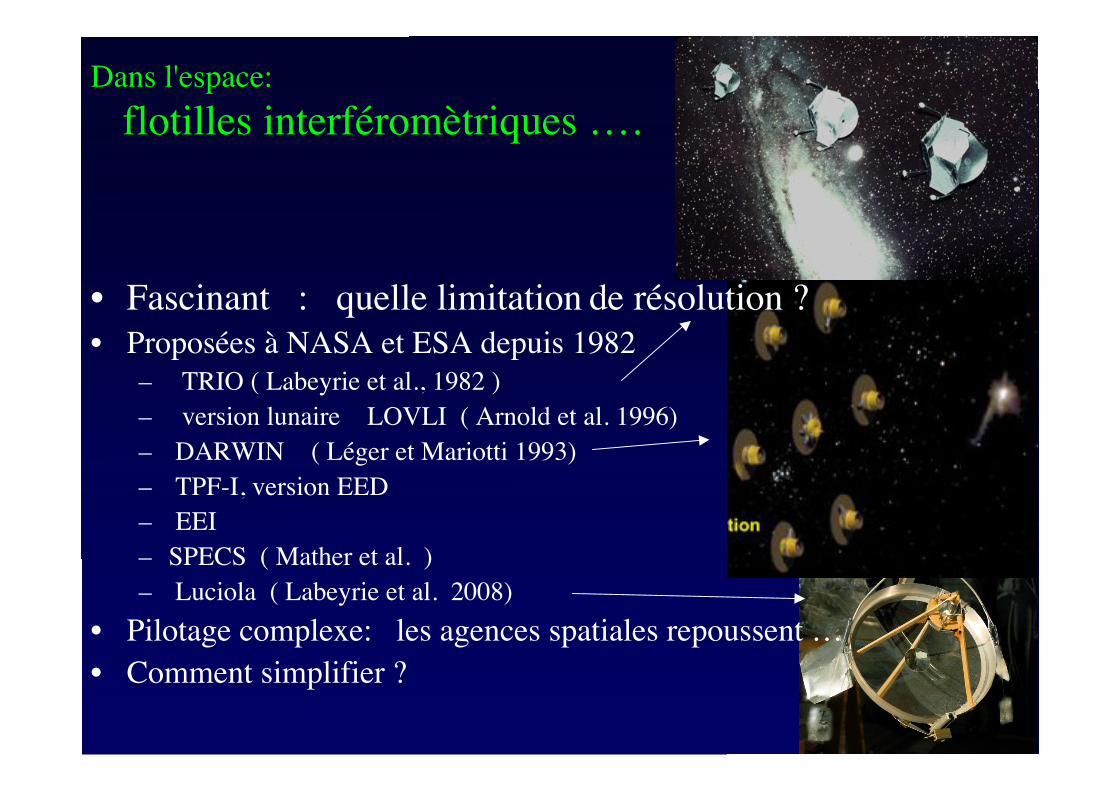
• Fascinant : quelle limitation de résolution ?
• Proposées à NASA et ESA depuis 1982
– TRIO ( Labeyrie et al., 1982 )
– version lunaire LOVLI ( Arnold et al. 1996)
– DARWIN ( Léger et Mariotti 1993)
– TPF-I, version EED
– EEI
– SPECS ( Mather et al. )
– Luciola! ( Labeyrie et al. 2008)
• Pilotage complexe: les agences spatiales repoussent …
• Comment simplifier ?
Dans l'espace:
flotilles interféromètriques ….
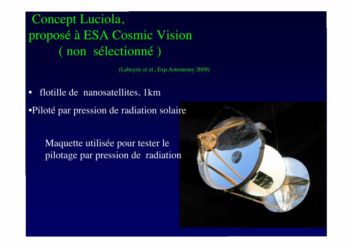
Concept Luciola,
proposé à ESA Cosmic Vision
( non sélectionné )
(Labeyrie et al., Exp.Astronomy 2009)
• flotille de nanosatellites, 1km
•Piloté par pression de radiation solaire
Maquette utilisée pour tester le
pilotage par pression de radiation
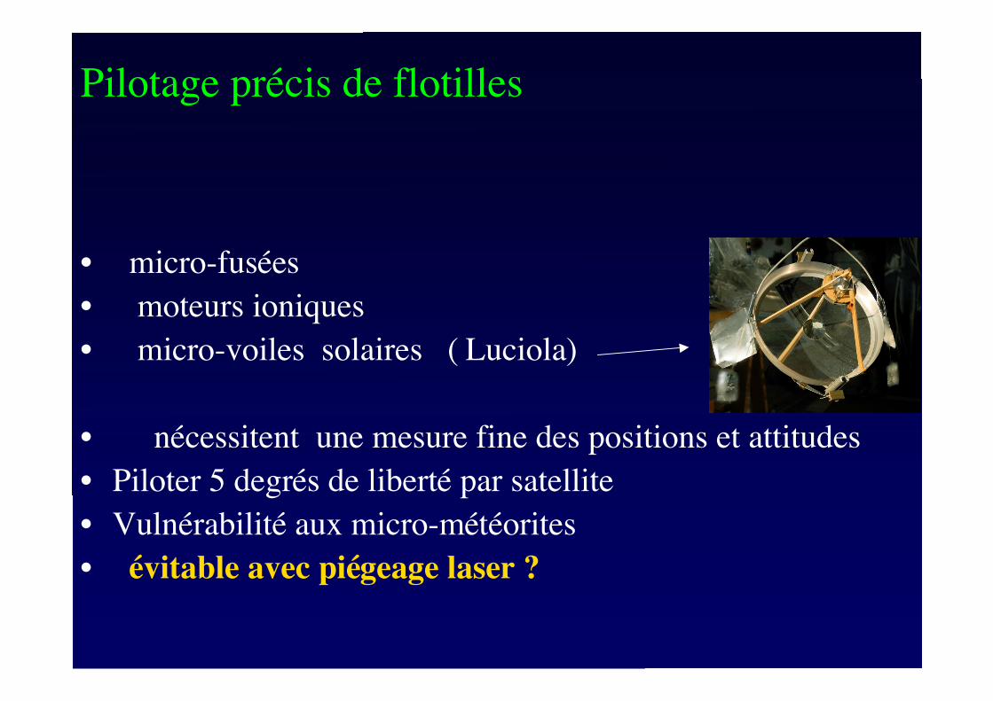
• micro-fusées
• moteurs ioniques
• micro-voiles solaires ( Luciola)
• nécessitent une mesure fine des positions et attitudes
• Piloter 5 degrés de liberté par satellite
• Vulnérabilité aux micro-météorites
• évitable avec piégeage laser ?
Pilotage précis de flotilles
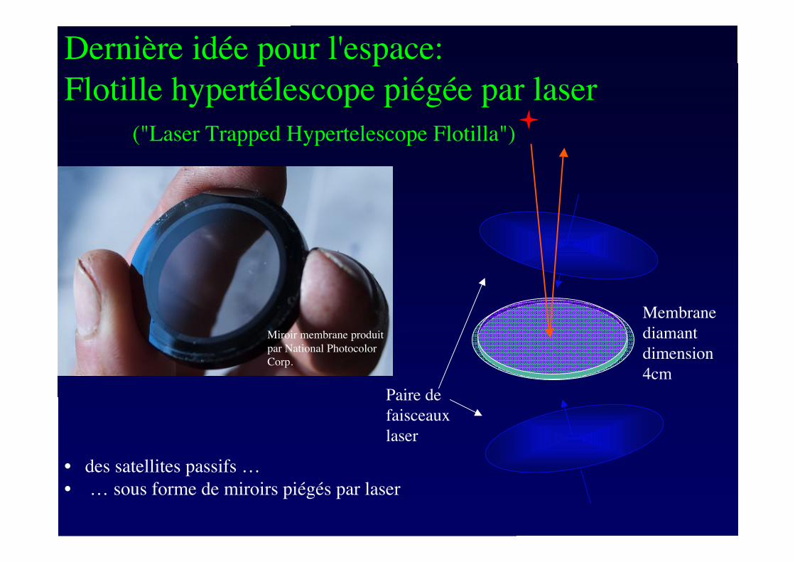
Dernière idée pour l'espace:
Flotille hypertélescope piégée par laser
("Laser Trapped Hypertelescope Flotilla")
Miroir membrane produit
par National Photocolor
Corp.
Membrane
diamant
dimension
4cm
Paire de
faisceaux
laser
• des satellites passifs …
• … sous forme de miroirs piégés par laser
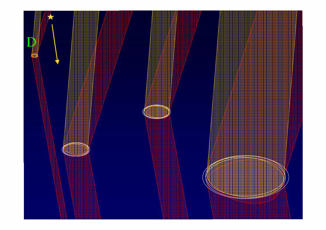
D
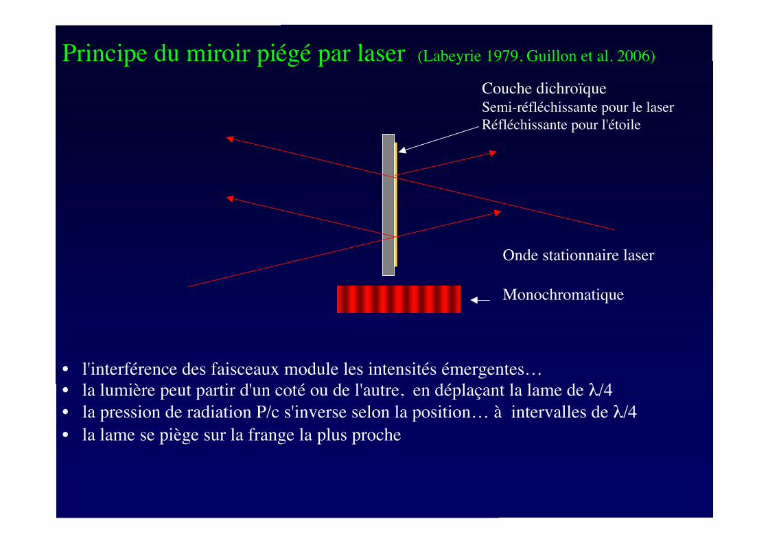
Principe du miroir piégé par laser (Labeyrie 1979, Guillon et al. 2006)
M
pa
M
c1M
c2
M
T
M
T
Figure 6 : Ray trace of Gregorian telescope for solar propulsion. The solar pointing is offset by one
solar radius to show the light path to lateral mirror MT and the sunward exit. The solar torque tends to
correct the pointing error, thus ensuring a passive stability in addition to the active stability obtained by
tilting the Gregorian secondary mirror Mc2. Such tilting can move the solar image, focused on the
faceted pyramid mirror Mpa, to different facets, each of which is concave and relays the pupil onto a
differently oriented MT mirror . A stronger pointing error can direct the solar image outside of the
pyramid, as indicated by the tracing of the more oblique ( 4 degrees) incident beam ( dotted lines). It
becomes reflected from the primary mirror Mc1, and the ensuing solar torque also tends to repoint the
spaceship. With a larger pointing error, the beam reflected from Mc1 tmisses Mc2, thus preventing any
passive or active recovery. Hence the need for a retro-reflective tail ( not shown) which then becomes
illuminated and provides a passive restoring torque.
• l'interférence des faisceaux module les intensités émergentes…
• la lumière peut partir d'un coté ou de l'autre, en déplaçant la lame de !/4
• la pression de radiation P/c s'inverse selon la position… à intervalles de !/4
• la lame se piège sur la frange la plus proche
Couche dichroïqueSemi-réfléchissante pour le laser
Réfléchissante pour l'étoile
Onde stationnaire laser
Monochromatique
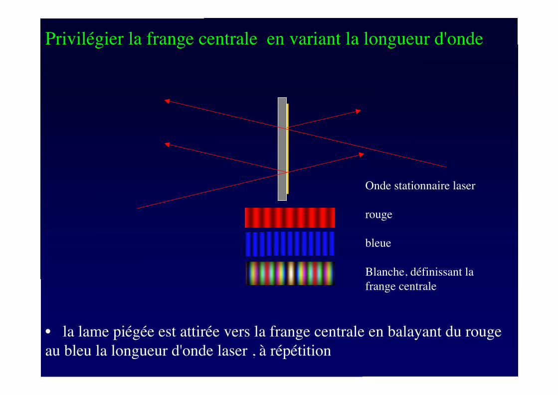
Privilégier la frange centrale en variant la longueur d'onde
M
pa
M
c1M
c2
M
T
M
T
Figure 6 : Ray trace of Gregorian telescope for solar propulsion. The solar pointing is offset by one
solar radius to show the light path to lateral mirror MT and the sunward exit. The solar torque tends to
correct the pointing error, thus ensuring a passive stability in addition to the active stability obtained by
tilting the Gregorian secondary mirror Mc2. Such tilting can move the solar image, focused on the
faceted pyramid mirror Mpa, to different facets, each of which is concave and relays the pupil onto a
differently oriented MT mirror . A stronger pointing error can direct the solar image outside of the
pyramid, as indicated by the tracing of the more oblique ( 4 degrees) incident beam ( dotted lines). It
becomes reflected from the primary mirror Mc1, and the ensuing solar torque also tends to repoint the
spaceship. With a larger pointing error, the beam reflected from Mc1 tmisses Mc2, thus preventing any
passive or active recovery. Hence the need for a retro-reflective tail ( not shown) which then becomes
illuminated and provides a passive restoring torque.
• la lame piégée est attirée vers la frange centrale en balayant du rouge
au bleu la longueur d'onde laser , à répétition
Onde stationnaire laser
rouge
bleue
Blanche, définissant la
frange centrale
Miroir membrane
produit par National
Photocolor Corp.
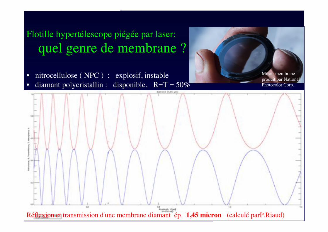
Réflexion et transmission d'une membrane diamant ép. 1,45 micron (calculé parP.Riaud)
• nitrocellulose ( NPC ) : explosif, instable
• diamant polycristallin : disponible, R=T = 50%
Flotille hypertélescope piégée par laser:
quel genre de membrane ?
M
pa
M
c1M
c2
M
T
M
T
Figure 6 : Ray trace of Gregorian telescope for solar propulsion. The solar pointing is offset by one
solar radius to show the light path to lateral mirror MT and the sunward exit. The solar torque tends to
correct the pointing error, thus ensuring a passive stability in addition to the active stability obtained by
tilting the Gregorian secondary mirror Mc2. Such tilting can move the solar image, focused on the
faceted pyramid mirror Mpa, to different facets, each of which is concave and relays the pupil onto a
differently oriented MT mirror . A stronger pointing error can direct the solar image outside of the
pyramid, as indicated by the tracing of the more oblique ( 4 degrees) incident beam ( dotted lines). It
becomes reflected from the primary mirror Mc1, and the ensuing solar torque also tends to repoint the
spaceship. With a larger pointing error, the beam reflected from Mc1 tmisses Mc2, thus preventing any
passive or active recovery. Hence the need for a retro-reflective tail ( not shown) which then becomes
illuminated and provides a passive restoring torque.
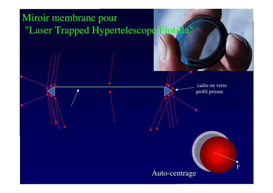
Miroir membrane pour
"Laser Trapped Hypertelescope Flotilla"
cadre en verre
profil prisme
Auto-centrageF
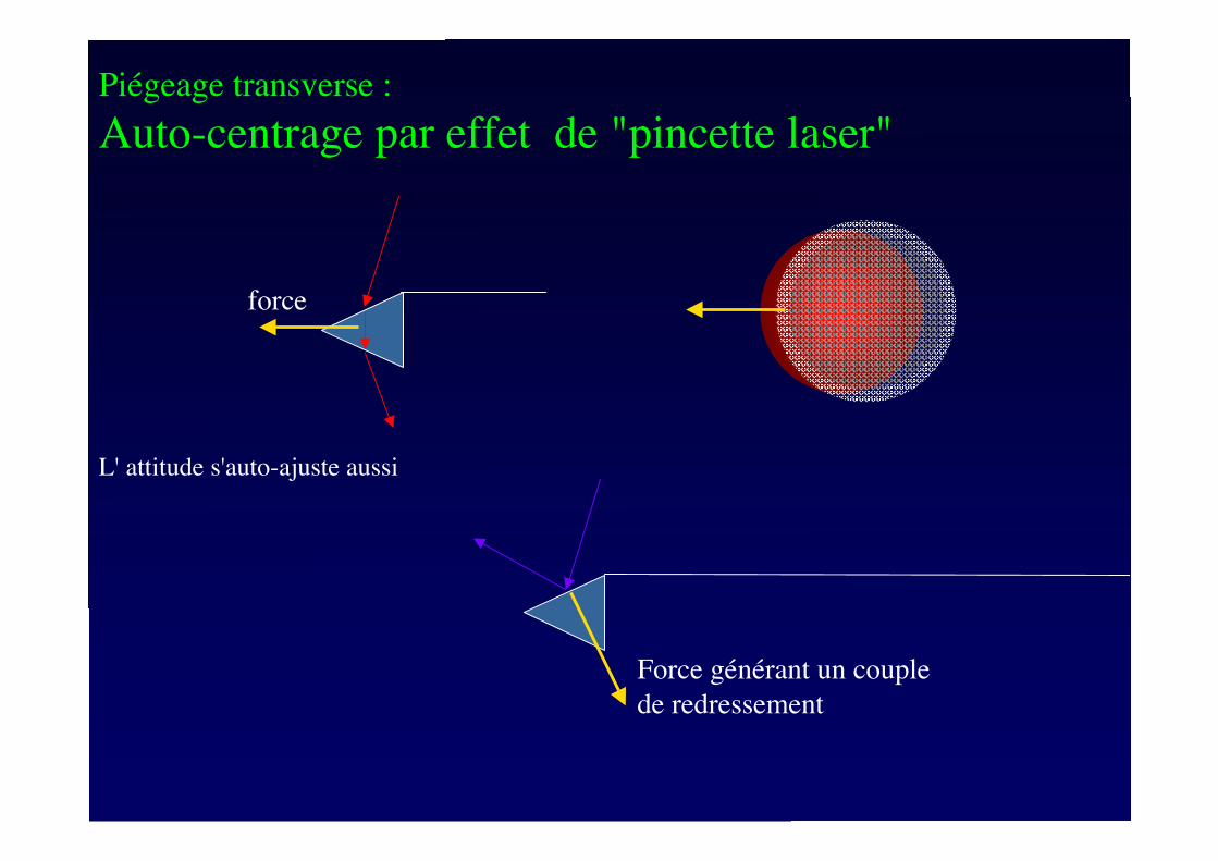
Piégeage transverse :
Auto-centrage par effet de "pincette laser"
L' attitude s'auto-ajuste aussi
force
Force générant un couple
de redressement
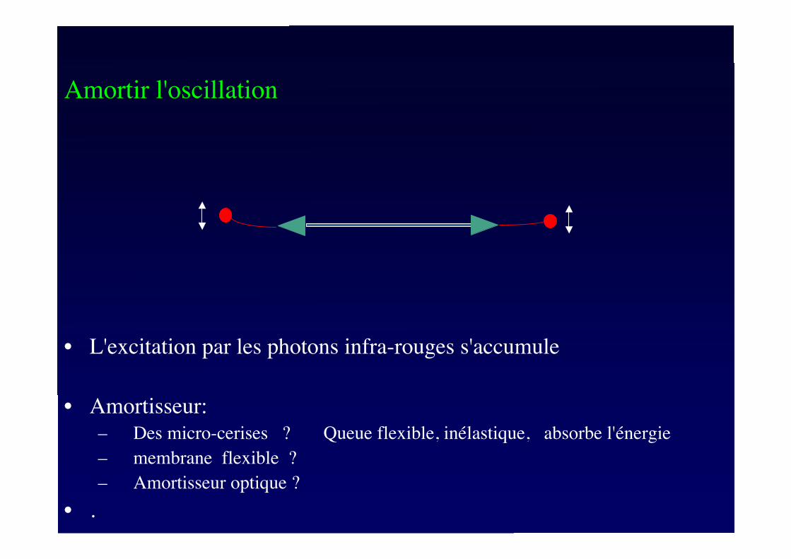
• L'excitation par les photons infra-rouges s'accumule
• Amortisseur:
– Des micro-cerises ? Queue flexible, inélastique, absorbe l'énergie
– membrane flexible ?
– Amortisseur optique ?
• .
!
Amortir l'oscillation
!
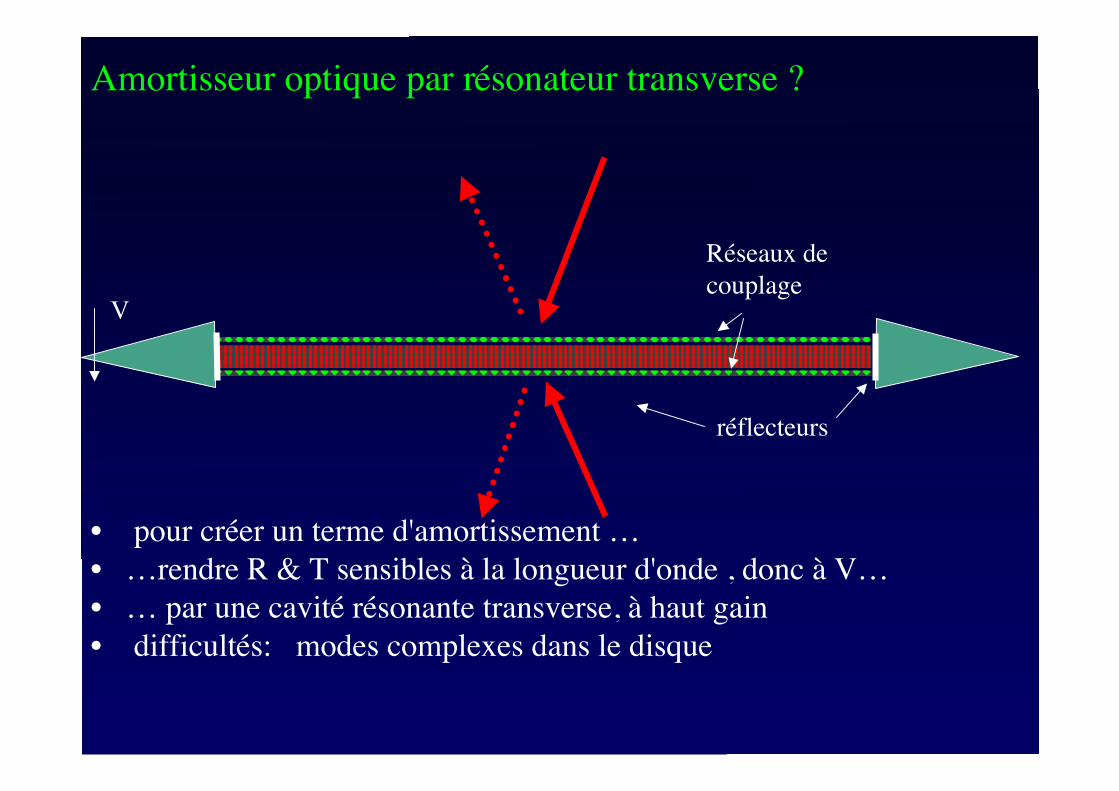
Amortisseur optique par résonateur transverse ?
• pour créer un terme d'amortissement …
• …rendre R & T sensibles à la longueur d'onde , donc à V…
• … par une cavité résonante transverse, à haut gain
• difficultés: modes complexes dans le disque
Réseaux de
couplageV
réflecteurs
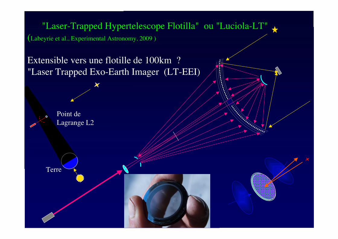
"Laser-Trapped Hypertelescope Flotilla" ou "Luciola-LT"
(Labeyrie et al., Experimental Astronomy, 2009 )
Extensible vers une flotille de 100km ?
"Laser Trapped Exo-Earth Imager (LT-EEI)
Point de
Lagrange L2
Terre
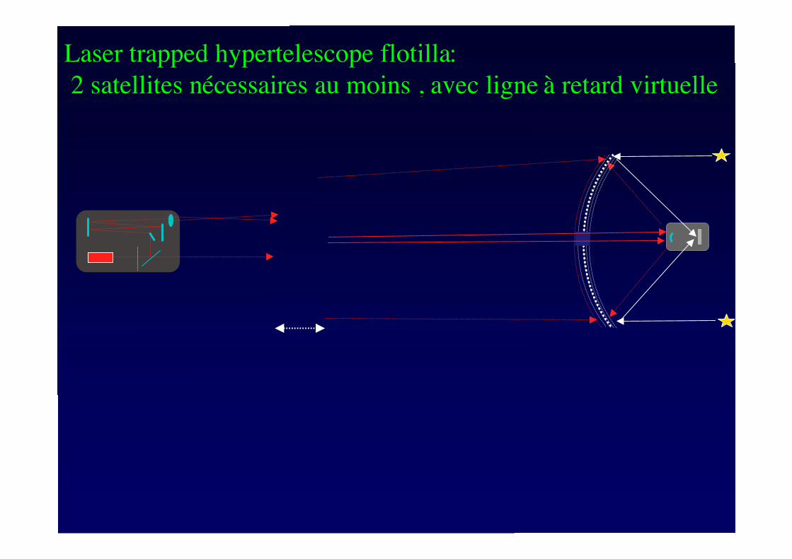
Laser trapped hypertelescope flotilla:
2 satellites nécessaires au moins , avec ligne à retard virtuelle
M
pa
M
c1M
c2
M
T
M
T
Figure 6 : Ray trace of Gregorian telescope for solar propulsion. The solar pointing is offset by one
solar radius to show the light path to lateral mirror MT and the sunward exit. The solar torque tends to
correct the pointing error, thus ensuring a passive stability in addition to the active stability obtained by
tilting the Gregorian secondary mirror Mc2. Such tilting can move the solar image, focused on the
faceted pyramid mirror Mpa, to different facets, each of which is concave and relays the pupil onto a
differently oriented MT mirror . A stronger pointing error can direct the solar image outside of the
pyramid, as indicated by the tracing of the more oblique ( 4 degrees) incident beam ( dotted lines). It
becomes reflected from the primary mirror Mc1, and the ensuing solar torque also tends to repoint the
spaceship. With a larger pointing error, the beam reflected from Mc1 tmisses Mc2, thus preventing any
passive or active recovery. Hence the need for a retro-reflective tail ( not shown) which then becomes
illuminated and provides a passive restoring torque.
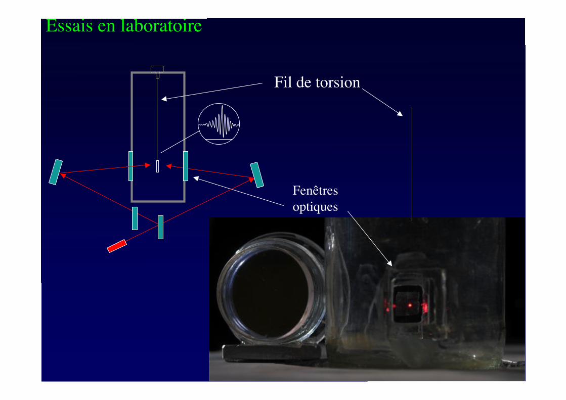
Essais en laboratoire
Fil de torsion
Fenêtres
optiques
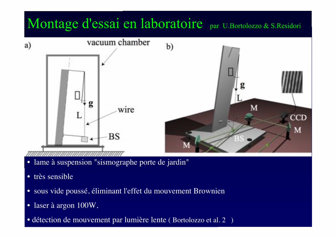
Montage d'essai en laboratoire par U.Bortolozzo & S.Residori
• lame à suspension "sismographe porte de jardin"
• très sensible
• sous vide poussé, éliminant l'effet du mouvement Brownien
• laser à argon 100W,
• détection de mouvement par lumière lente ( Bortolozzo et al. 2 )
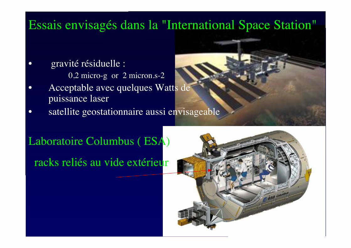
• gravité résiduelle :
0,2 micro-g or 2 micron.s-2
• Acceptable avec quelques Watts depuissance laser
• satellite geostationnaire aussi envisageable
Essais envisagés dans la "International Space Station"
Laboratoire Columbus ( ESA)
racks reliés au vide extérieur