Cube 300 et 370 micro-watt VMC double flux - pro.aldes.fr · 5 1 .4 .3 Utilisation • En cas...
120
Notice de Montage www.aldes.com Cube 300 et 370 micro-watt VMC double flux GB p. 25 D S. 49 NL p. 73 I p. 97
Transcript of Cube 300 et 370 micro-watt VMC double flux - pro.aldes.fr · 5 1 .4 .3 Utilisation • En cas...
N o t i c e d e M o n t a g e
www.aldes.com
Cube 300 et 370 micro-watt VMC double flux
GB p. 25D S. 49
NL p. 73I p. 97
2
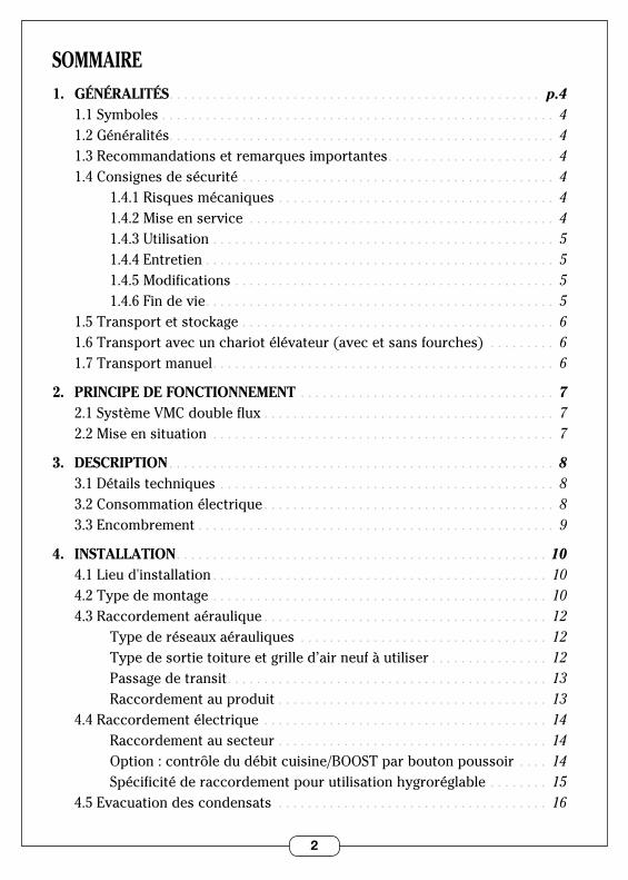
1. GÉNÉRALITÉS . . . . . . . . . . . . . . . . . . . . . . . . . . . . . . . . . . . . . . . . . . . . . . . . . . . p.4 1 .1 Symboles . . . . . . . . . . . . . . . . . . . . . . . . . . . . . . . . . . . . . . . . . . . . . . . . . . . . . . 4 1 .2 Généralités . . . . . . . . . . . . . . . . . . . . . . . . . . . . . . . . . . . . . . . . . . . . . . . . . . . . . 4 1 .3 Recommandations et remarques importantes . . . . . . . . . . . . . . . . . . . . . . . 4 1 .4 Consignes de sécurité . . . . . . . . . . . . . . . . . . . . . . . . . . . . . . . . . . . . . . . . . . . 4 1 .4 .1 Risques mécaniques . . . . . . . . . . . . . . . . . . . . . . . . . . . . . . . . . . . . . . 4 1 .4 .2 Mise en service . . . . . . . . . . . . . . . . . . . . . . . . . . . . . . . . . . . . . . . . . . 4 1 .4 .3 Utilisation . . . . . . . . . . . . . . . . . . . . . . . . . . . . . . . . . . . . . . . . . . . . . . . 5 1 .4 .4 Entretien . . . . . . . . . . . . . . . . . . . . . . . . . . . . . . . . . . . . . . . . . . . . . . . . 5 1 .4 .5 Modifications . . . . . . . . . . . . . . . . . . . . . . . . . . . . . . . . . . . . . . . . . . . . 5 1 .4 .6 Fin de vie . . . . . . . . . . . . . . . . . . . . . . . . . . . . . . . . . . . . . . . . . . . . . . . . 5 1 .5 Transport et stockage . . . . . . . . . . . . . . . . . . . . . . . . . . . . . . . . . . . . . . . . . . . 6 1 .6 Transport avec un chariot élévateur (avec et sans fourches) . . . . . . . . . 6 1 .7 Transport manuel . . . . . . . . . . . . . . . . . . . . . . . . . . . . . . . . . . . . . . . . . . . . . . . 6
2. PRINCIPE DE FONCTIONNEMENT . . . . . . . . . . . . . . . . . . . . . . . . . . . . . . . . . . . 7 2 .1 Système VMC double flux . . . . . . . . . . . . . . . . . . . . . . . . . . . . . . . . . . . . . . . . 7 2 .2 Mise en situation . . . . . . . . . . . . . . . . . . . . . . . . . . . . . . . . . . . . . . . . . . . . . . . 7
3. DESCRIPTION . . . . . . . . . . . . . . . . . . . . . . . . . . . . . . . . . . . . . . . . . . . . . . . . . . . . . 8 3 .1 Détails techniques . . . . . . . . . . . . . . . . . . . . . . . . . . . . . . . . . . . . . . . . . . . . . . 8 3 .2 Consommation électrique . . . . . . . . . . . . . . . . . . . . . . . . . . . . . . . . . . . . . . . . 8 3 .3 Encombrement . . . . . . . . . . . . . . . . . . . . . . . . . . . . . . . . . . . . . . . . . . . . . . . . . 9
4. INSTALLATION . . . . . . . . . . . . . . . . . . . . . . . . . . . . . . . . . . . . . . . . . . . . . . . . . . . 10 4 .1 Lieu d'installation . . . . . . . . . . . . . . . . . . . . . . . . . . . . . . . . . . . . . . . . . . . . . . 10 4 .2 Type de montage . . . . . . . . . . . . . . . . . . . . . . . . . . . . . . . . . . . . . . . . . . . . . . 10 4 .3 Raccordement aéraulique . . . . . . . . . . . . . . . . . . . . . . . . . . . . . . . . . . . . . . . 12 Type de réseaux aérauliques . . . . . . . . . . . . . . . . . . . . . . . . . . . . . . . . . . 12 Type de sortie toiture et grille d’air neuf à utiliser . . . . . . . . . . . . . . . . 12 Passage de transit . . . . . . . . . . . . . . . . . . . . . . . . . . . . . . . . . . . . . . . . . . . . 13 Raccordement au produit . . . . . . . . . . . . . . . . . . . . . . . . . . . . . . . . . . . . . 13 4 .4 Raccordement électrique . . . . . . . . . . . . . . . . . . . . . . . . . . . . . . . . . . . . . . . 14 Raccordement au secteur . . . . . . . . . . . . . . . . . . . . . . . . . . . . . . . . . . . . . 14 Option : contrôle du débit cuisine/BOOST par bouton poussoir . . . . 14 Spécificité de raccordement pour utilisation hygroréglable . . . . . . . . 15 4 .5 Evacuation des condensats . . . . . . . . . . . . . . . . . . . . . . . . . . . . . . . . . . . . . 16
SOMMAIRE
3
5. MISE EN SERVICE . . . . . . . . . . . . . . . . . . . . . . . . . . . . . . . . . . . . . . . . . . . . . . . . 17 5 .1 Vérification importante avant mise en service . . . . . . . . . . . . . . . . . . . . . 17 5 .2 Accès au clavier de paramétrage . . . . . . . . . . . . . . . . . . . . . . . . . . . . . . . . . 17 5 .3 Paramétrage usine . . . . . . . . . . . . . . . . . . . . . . . . . . . . . . . . . . . . . . . . . . . . . 18 5 .4 Réglage des paramètres . . . . . . . . . . . . . . . . . . . . . . . . . . . . . . . . . . . . . . . . 18
6. UTILISATION . . . . . . . . . . . . . . . . . . . . . . . . . . . . . . . . . . . . . . . . . . . . . . . . . . . . 19 6 .1 Réglage du débit de ventilation . . . . . . . . . . . . . . . . . . . . . . . . . . . . . . . . . . 19 6 .2 Choix du mode confort . . . . . . . . . . . . . . . . . . . . . . . . . . . . . . . . . . . . . . . . . 19
7. ENTRETIEN . . . . . . . . . . . . . . . . . . . . . . . . . . . . . . . . . . . . . . . . . . . . . . . . . . . . . . 20 7 .1 Remplacement des filtres . . . . . . . . . . . . . . . . . . . . . . . . . . . . . . . . . . . . . . . 20 7 .2 Niveau d’eau du siphon . . . . . . . . . . . . . . . . . . . . . . . . . . . . . . . . . . . . . . . . . 20 7 .3 Réseau aéraulique, sortie toiture et grille d’air neuf . . . . . . . . . . . . . . . . . 21 7 .4 Nettoyage de l’échangeur . . . . . . . . . . . . . . . . . . . . . . . . . . . . . . . . . . . . . . . 21
8. ANOMALIES DE FONCTIONNEMENT . . . . . . . . . . . . . . . . . . . . . . . . . . . . . . . . 22
9. PIÈCES DÉTACHÉES . . . . . . . . . . . . . . . . . . . . . . . . . . . . . . . . . . . . . . . . . . . . . . 22
10. GARANTIE . . . . . . . . . . . . . . . . . . . . . . . . . . . . . . . . . . . . . . . . . . . . . . . . . . . . . . . 23 10 .1 Conditions générales de garantie . . . . . . . . . . . . . . . . . . . . . . . . . . . . . . . . 23 10 .2 Durée de la garantie . . . . . . . . . . . . . . . . . . . . . . . . . . . . . . . . . . . . . . . . . . . 23 10 .3 Conditions d’exclusion de la garantie . . . . . . . . . . . . . . . . . . . . . . . . . . . . 23 10 .4 Service après-vente . . . . . . . . . . . . . . . . . . . . . . . . . . . . . . . . . . . . . . . . . . . 23
4
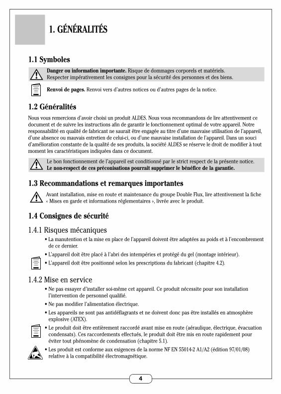
1.1 Symboles Danger ou information importante. Risque de dommages corporels et matériels . Respecter impérativement les consignes pour la sécurité des personnes et des biens .
Renvoi de pages. Renvoi vers d’autres notices ou d’autres pages de la notice .
1.2 GénéralitésNous vous remercions d’avoir choisi un produit ALDES . Nous vous recommandons de lire attentivement ce document et de suivre les instructions afin de garantir le fonctionnement optimal de votre appareil . Notre responsabilité en qualité de fabricant ne saurait être engagée au titre d’une mauvaise utilisation de l’appareil, d’une absence ou mauvais entretien de celui-ci, ou d’une mauvaise installation de l’appareil . Dans un souci d’amélioration constante de la qualité de ses produits, la société ALDES se réserve le droit de modifier à tout moment les caractéristiques indiquées dans ce document .
Le bon fonctionnement de l’appareil est conditionné par le strict respect de la présente notice . Le non-respect de ces préconisations pourrait supprimer le bénéfice de la garantie.
1.3 Recommandations et remarques importantes Avant installation, mise en route et maintenance du groupe Double Flux, lire attentivement la fiche
« Mises en garde et informations réglementaires », livrée avec le produit .
1.4 Consignes de sécurité
1 .4 .1 Risques mécaniques •Lamanutentionetlamiseenplacedel’appareildoiventêtreadaptéesaupoidsetàl’encombrement
de ce dernier .
•L’appareildoitêtreplacéàl’abridesintempériesetprotégédugel(montageintérieur).
•L’appareildoitêtrepositionnéselonlesprescriptionsdufabricant(chapitre4.2).
1 .4 .2 Mise en service •Nepasessayerd’installersoi-mêmecetappareil.Ceproduitnécessitepoursoninstallation
l’intervention de personnel qualifié .
•Nepasmodifierl’alimentationélectrique.
•Lesappareilsnesontpasantidéflagrantsetnedoiventdoncpasêtreinstallésenatmosphèreexplosive (ATEX) .
•Leproduitdoitêtreentièrementraccordéavantmiseenroute(aéraulique,électrique,évacuation condensats) . Ces raccordements effectués, le produit doit être mis en route rapidement pour éviter tout phénomène de condensation (chapitre 5 .1).
•LesproduitestconformeauxexigencesdelanormeNFEN55014-2A1/A2(édition97/01/08)relative à la compatibilité électromagnétique .
1. GÉNÉRALITÉS
5
1 .4 .3 Utilisation •Encasd’anomaliedefonctionnement,faireappelàunprofessionnel.
•Nepasintroduiredecorpsétrangersdanslesbouchesd’entréeetsortied’air.
•Aucunobstaclenedoitentraverlacirculationdel’air.
•Nepasmontersurlechâssisdusystème.
•Votrelocalrépondantàdesnormesdesécurité,nepasyapporterdemodifications(ventilation, conduit de fumées, ouverture, etc .) sans l’avis de votre installateur .
1 .4 .4 Entretien •Nepasessayerderéparervotreappareilvous-même.
•Cetappareilnecontientaucunepiècesusceptibled’êtreréparéeparl’utilisateurlui-même.Démonter un des capots peut vous exposer à des tensions électriques dangereuses .
•Couperl’alimentationélectriquen’estenaucuncassuffisantpourvousprotégerd’éventuelschocs électriques (condensateurs) .
•Couperl’alimentationélectriquesidesbruitsanormaux,desodeursoudelafuméeproviennent de l’appareil et contacter votre installateur .
•Avanttoutnettoyageéventuel,couperl’alimentationélectriquesurl’appareil.
•Nepasutiliserdeliquidedenettoyageagressifoudesolvantspournettoyerl’appareil.
•Nepasutiliserdenettoyeursouspressionpournettoyerlesbouchesd’air.Vousrisquezde détériorer l’échangeur à air et de faire pénétrer de l’eau dans les circuits électriques .
1 .4 .5 Transformation •Toutemodificationdel’appareilestinterdite.Toutremplacementdecomposantsdoitêtre
effectué par un professionnel avec des pièces adaptées d’origine du constructeur .
1 .4 .6 Fin de vie •Avantdémontagedel’appareilmettrecelui-cihorstension.
•Lacombustiondecertainscomposantspeutdégagerdesgaztoxiques,nepasincinérerl’appareil.
6
VUE 3/4 AVANT BARQUETTE DESSUS
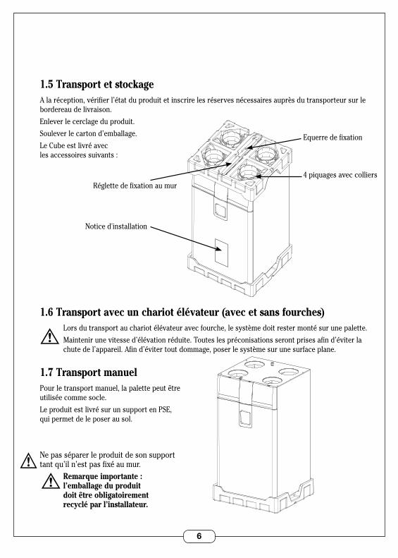
4 piquages avec colliers
Notice d'installation
Equerre de fixation
Réglette de fixation au mur
VUE 3/4 AVANT BARQUETTE DESSOUS
1.5 Transport et stockageA la réception, vérifier l’état du produit et inscrire les réserves nécessaires auprès du transporteur sur le bordereau de livraison .
Enlever le cerclage du produit .
Soulever le carton d’emballage .
Le Cube est livré avec les accessoires suivants :
1.6 Transport avec un chariot élévateur (avec et sans fourches) Lors du transport au chariot élévateur avec fourche, le système doit rester monté sur une palette .
Maintenir une vitesse d’élévation réduite . Toutes les préconisations seront prises afin d’éviter la chute de l’appareil . Afin d’éviter tout dommage, poser le système sur une surface plane .
1.7 Transport manuelPour le transport manuel, la palette peut être utilisée comme socle .
Le produit est livré sur un support en PSE, qui permet de le poser au sol .
Ne pas séparer le produit de son support tant qu’il n’est pas fixé au mur . Remarque importante : l’emballage du produit doit être obligatoirement recyclé par l’installateur.
7
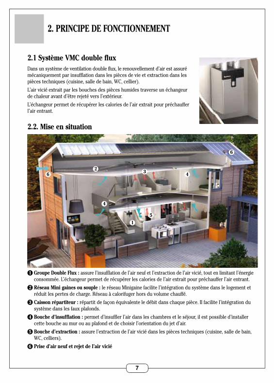
2.1 Système VMC double flux Dans un système de ventilation double flux, le renouvellement d’air est assuré mécaniquement par insufflation dans les pièces de vie et extraction dans les pièces techniques (cuisine, salle de bain, WC, cellier) .
L’air vicié extrait par les bouches des pièces humides traverse un échangeur de chaleur avant d’être rejeté vers l’extérieur .
L’échangeur permet de récupérer les calories de l’air extrait pour préchauffer l’air entrant .
2.2. Mise en situation
1 Groupe Double Flux : assure l’insufflation de l’air neuf et l’extraction de l’air vicié, tout en limitant l’énergie consommée . L’échangeur permet de récupérer les calories de l’air extrait pour préchauffer l’air entrant .
2 Réseau Mini gaines ou souple : le réseau Minigaine facilite l’intégration du système dans le logement et réduit les pertes de charge . Réseau à calorifuger hors du volume chauffé .
3 Caisson répartiteur : répartit de façon équivalente le débit dans chaque pièce . Il facilite l’intégration du système dans les faux plafonds .
4 Bouche d’insufflation : permet d’insuffler l’air dans les chambres et le séjour, il est possible d’installer cette bouche au mur ou au plafond et de choisir l’orientation du jet d’air .
5 Bouche d’extraction : assure l’extraction de l’air vicié dans les pièces techniques (cuisine, salle de bain, WC, celliers) .
6 Prise d’air neuf et rejet de l’air vicié
2. PRINCIPE DE FONCTIONNEMENT
62
6
1
4
4
5
3
8
3.1 Détails techniques
Construction groupe Double Flux
Enveloppe TôleRAL9006
Habillage interne PSE
Echangeur Polystyrène
Moteurs Micro-watt avec protection thermique .
Filtres F7surairneuf:270x240x48 G4surairvicié:280x240x10
By-pass 100%, automatique
Clavier utilisateur Sur face avant groupe
Clavier installateur Sur carte électronique
Raccordements aérauliques 4 piquages circulaires Diam 160
Domaines d'emploiConfiguration Mini 90m3/h
Configuration Maxi 370 m3/h
Températures limites d'utilisationLocal d'installation 5°C / 60°C
Air neuf ou extrait -7°C / 40°C sans batterie -20°C / 40°C avec batterie
Electrique
Alimentation Monophasé230V–50Hz
Protection électrique IPX2
Classe Classe 1
Puissance maxi 340 W
Intensité maxi 2,5 A
Protection contre le gelDébit d'air automatique équilibré afin d'empêcher tout risque pour l'échangeur . Option : Batterie de préchauffage pour éviter à l'échangeur de geler et maintenir l'équilibre du débit d'air .
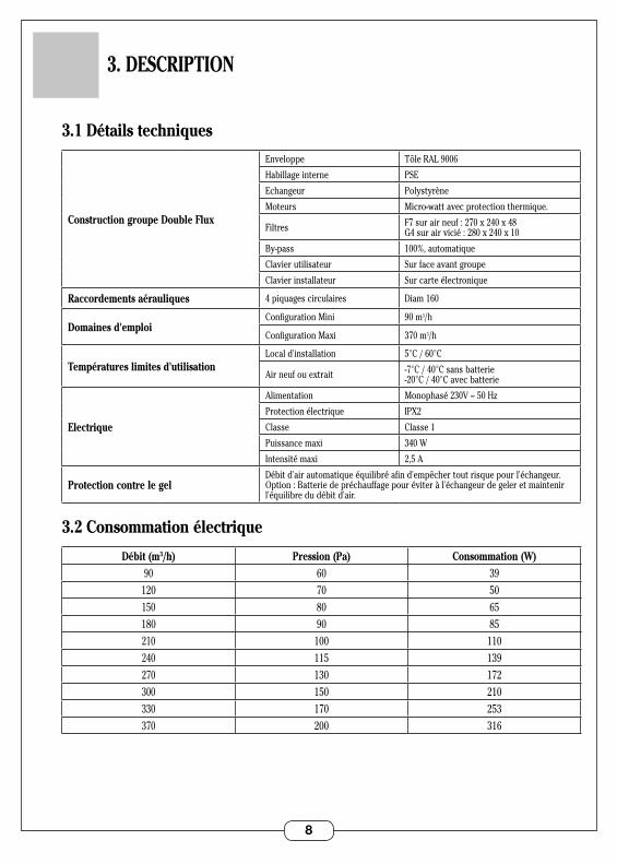
3.2 Consommation électrique
Débit (m3/h) Pression (Pa) Consommation (W)90 60 39
120 70 50150 80 65180 90 85210 100 110240 115 139270 130 172300 150 210330 170 253370 200 316
3. DESCRIPTION
9
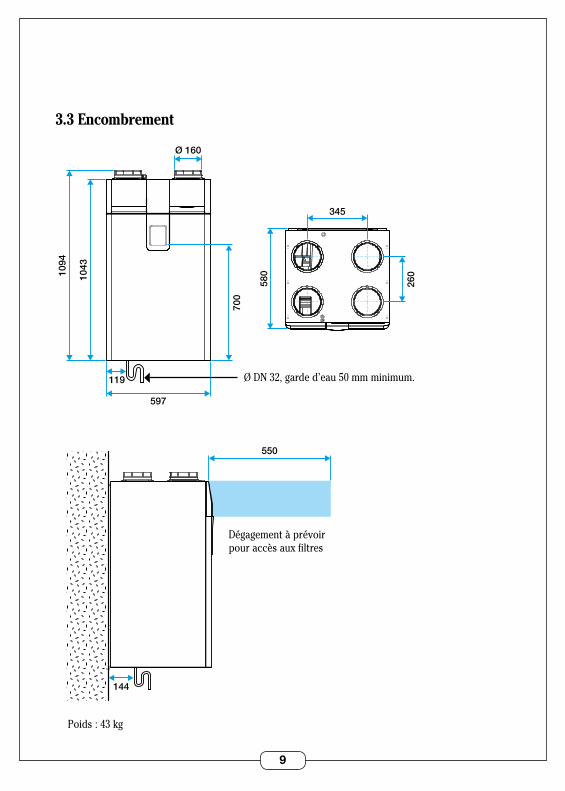
3.3 Encombrement
1094
1043
597
119
580
700
345
Ø 160
260
144
550
Ø DN 32, garde d’eau 50 mm minimum .
Dégagement à prévoirpour accès aux filtres
Poids : 43 kg
10
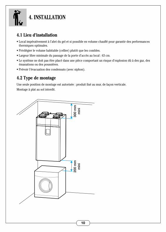
4.1 Lieu d'installation•Localimpérativementàl’abridugeletsipossibleenvolumechauffépourgarantirdesperformances
thermiques optimales .
•Privilégierlevolumehabitable(cellier)plutôtquelescombles.
•Largeurlibreminimaledupassagedelaported’accèsaulocal:63cm.
•Lesystèmenedoitpasêtreplacédansunepiècecomportantunrisqued’explosiondûàdesgaz,des émanations ou des poussières .
•Prévoirl’évacuationdescondensats(avecsiphon).
4.2 Type de montageUne seule position de montage est autorisée : produit fixé au mur, de façon verticale .
Montage à plat au sol interdit .
200
mm
min
i30
0 m
mm
ini
4. INSTALLATION
11
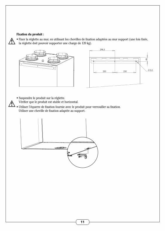
Fixation du produit :
•Fixerlarégletteaumur,enutilisantleschevillesdefixationadaptéesaumursupport(unefoisfixée, la réglette doit pouvoir supporter une charge de 120 kg) .
•Suspendreleproduitsurlaréglette. Vérifierqueleproduiteststableethorizontal.
•Utiliserl’équerredefixationfournieavecleproduitpourverrouillersafixation. Utiliser une cheville de fixation adaptée au support .
5,2
46
250 250
298,3
VUE ARRIERE SUPPORT MURAL
5,2
46
250 250
298,3
VUE ARRIERE SUPPORT MURAL
VUE 3/4 DESSOUS EQUERRE MURALE
VUE 3/4 DESSOUS EQUERRE MURALE
12
4.3 Raccordement aéraulique
Type de réseaux aérauliquesLe produit peut être utilisé avec plusieurs types de réseaux :
•GainesoupletypeAlgaine(prévoiruneisolationde50mmminimumsiutilisationenvolumenonchauffé).
•GainerigidetypeMinigaine(envolumechaufféexclusivement).
•GainesemirigidetypeFlexigaine(envolumechaufféexclusivement).
Recommandations au montage des conduits : •Lesconduitssouplesdoiventêtresuspendus. •Eviterlescoudesinutiles. •Veilleràcequelesconduitsnesoientpasécrasés.
Type de sortie toiture et grille d’air neuf à utiliser Pour minimiser les pertes de charge, le produit doit être utilisé comme suit :
Rejet d’air vicié :•Soitsortietoitureendiamètre160,typeSTS•Soitgrilleenfaçade,typeAWA251300x300.
Aspiration air neuf :•Grilleenfaçade,typeAWA251300x300.
L’arrivée d’air neuf et l’extraction d’air vicié doivent être disposés sur deux pans de mur différents ou distantsd’aumoins8mètres,pourévitertoutrecyclage.
La grille doit être placée de telle sorte qu’elle soit hors d’eau et non colmatable . Attention à sa localisation (cheminée, parking véhicules) .
La sortie toiture et la prise d’air neuf doivent être reliés au produit par des conduits en diamètre 160 mm . Il est déconseillé d’aspirer l’air neuf par la toiture (risque d’aspiration d’eau ou de neige dans le groupe double flux) .
13
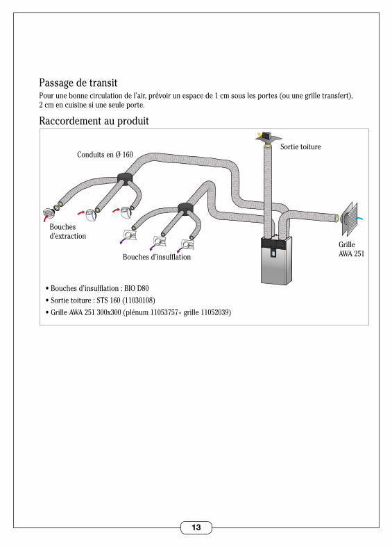
Passage de transitPour une bonne circulation de l’air, prévoir un espace de 1 cm sous les portes (ou une grille transfert), 2 cm en cuisine si une seule porte .
Raccordement au produit
Bouches d’insufflation
•Bouchesd’insufflation:BIOD80
•Sortietoiture:STS160(11030108)
•GrilleAWA251300x300(plénum11053757+grille11052039)
Bouches d'extraction
Conduits en Ø 160Sortie toiture
Grille AWA 251

14
4.4 Raccordement électrique
Raccordement au secteurL’appareil doit être raccordé par un professionnel suivant la norme locale . Raccorderlecâblefourniausecteurparl’intermédiaire d’une boite de raccordement étanche (non fournie) .
Sectiondecâble:3x1,5mm2
Réseau : courant alternatif 230 V monophasé .L’installation comportera :•Undisjoncteurbipolaire.
•Uneprotectionducircuitpardisjoncteur différentiel 30 mA .
Option : contrôle du débit cuisine/BOOST par bouton poussoirIl est possible de rajouter un bouton poussoir en cuisine pour contrôler . •Appuicourt:passagedevitesse2àvitesse3(pasdetemporisation).•Appuide3secondes:passagedevitesse3àvitesse4(pasdetemporisation).•Unnouvelappuipermetderepasseenvitesse2.
Démonter la trappe d’accès aux filtres de droite en appuyant sur les 2 boutons supérieurs .
Démonter la trappe d’accès à la carte électronique en enlevant la vis puis en appuyant sur le bouton supérieur .
VUE 3/4 DESSUS SORTIE CORDON
Connecteur 230V . Longueur de fil disponible : 1 m

15
Raccorder le bouton poussoir au connecteur ‘cuisine’ (pas de polarité) .
Section : 0,25 à 1,5 mm2
Spécificité de raccordement pour bouches BUSLes bouches BUS doivent être raccordées au Double Flux par une liaison de type courant faible . Section : 0,25 à 1,5 mm2 .
Accéder à la carte électronique .
Raccorder la bouche au connecteur ‘BUS’ (pas de polarité) .
Batterie de préchauffage : OptionLa batterie de préchauffage (11023225) doit être raccordée au connecteur ‘BUS’ (pas de polarité) .
16
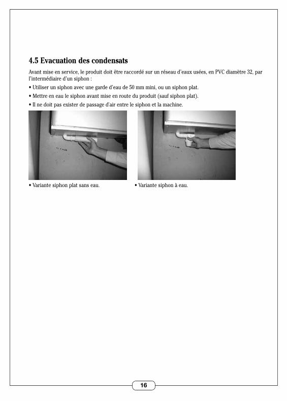
4.5 Evacuation des condensatsAvant mise en service, le produit doit être raccordé sur un réseau d’eaux usées, en PVC diamètre 32, par l’intermédiaire d’un siphon :
•Utiliserunsiphonavecunegarded’eaude50mmmini,ouunsiphonplat.
•Mettreeneaulesiphonavantmiseenrouteduproduit(saufsiphonplat).
•Ilnedoitpasexisterdepassaged'airentrelesiphonetlamachine.
•Variantesiphonplatsanseau.•Variantesiphonàeau.
17
5. MISE EN SERVICE
5.1 Vérification importante avant mise en serviceAvant mise sous tension, vérifier les éléments suivants :
•Vérifierquelecâbled’alimentationn’estpasendommagé.
•Vérifierlatensiond’alimentationetnotammentlabonnepositionduneutre.
•L’appareildoitimpérativementêtreraccordéàlaterre.
•Vérifierquelescouleursdesfilsdesraccordementscorrespondent.
•Contrôlerquelesgainesaérauliquessontbienraccordées.
•Vérifierquel’évacuationdescondensatsestbienraccordéeàunréseaud’eauxusées,parl’intermédiaire d’un siphon à eau .
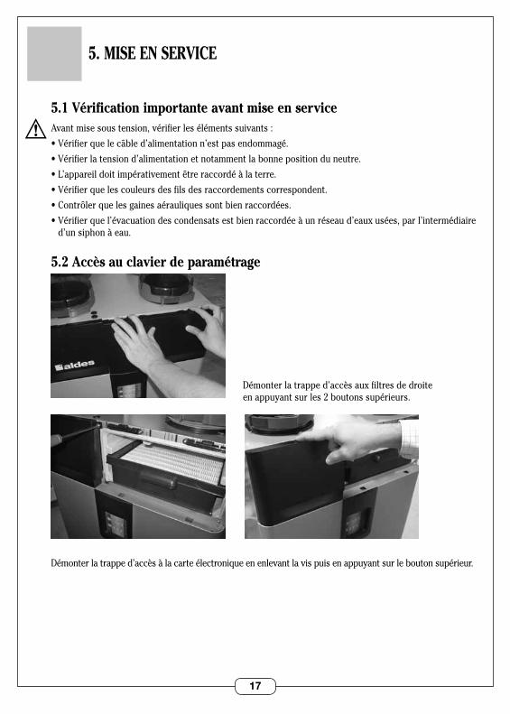
5.2 Accès au clavier de paramétrage
Démonter la trappe d’accès aux filtres de droite en appuyant sur les 2 boutons supérieurs .
Démonter la trappe d’accès à la carte électronique en enlevant la vis puis en appuyant sur le bouton supérieur .
18
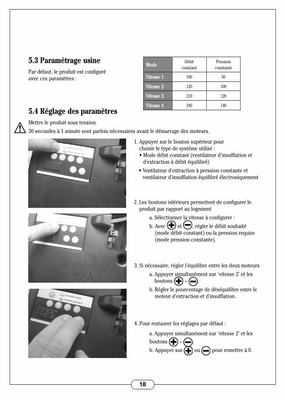
5.3 Paramétrage usinePar défaut, le produit est configuré avec ces paramètres :
5.4 Réglage des paramètresMettre le produit sous tension .
30 secondes à 1 minute sont parfois nécessaires avant le démarrage des moteurs .
1 . Appuyer sur le bouton supérieur pour choisir le type de système utilisé : •Modedébitconstant(ventilateurd'insufflationet
d'extraction à débit équilibré)
•Ventilateurd'extractionàpressionconstanteet ventilateur d'insufflation équilibré électroniquement
2 . Les boutons inférieurs permettent de configurer le produit par rapport au logement
a . Sélectionner la vitesse à configurer :
b . Avec et , régler le débit souhaité (mode débit constant) ou la pression requise (mode pression constante) .
3 . Si nécessaire, régler l'équilibre entre les deux moteurs
a . Appuyer simultanément sur ‘vitesse 2’ et les boutons + .
b . Régler le pourcentage de déséquilibre entre le moteur d'extraction et d'insufflation .
4 . Pour restaurer les réglages par défaut :
a . Appuyer simultanément sur ‘vitesse 2’ et les boutons + .
b . Appuyer sur ou pour remettre à 0 .
ModeDébit
constantPression
constante
Vitesse 1 100 50
Vitesse 2 120 100
Vitesse 3 210 120
Vitesse 4 240 140
19
6. UTILISATION
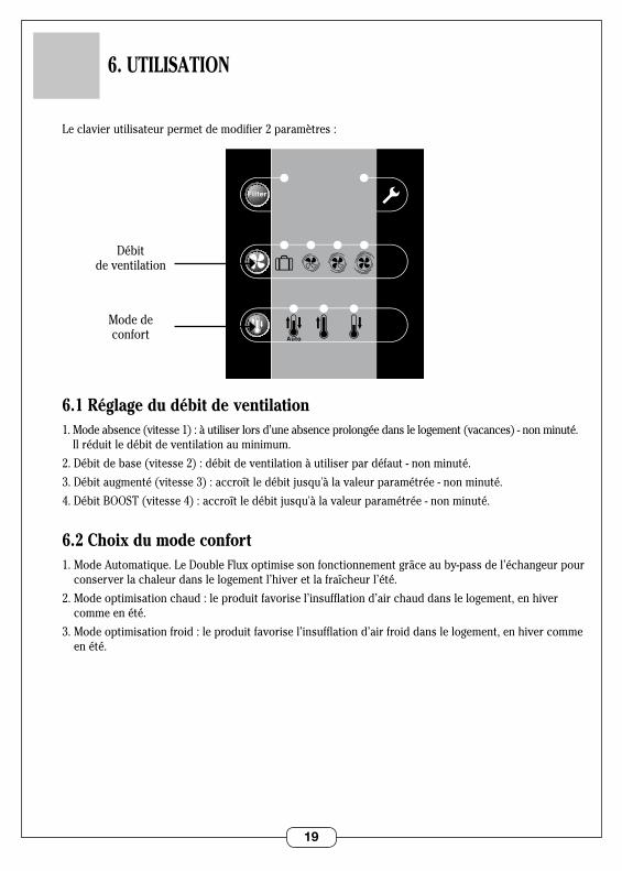
Le clavier utilisateur permet de modifier 2 paramètres :
6.1 Réglage du débit de ventilation1 . Mode absence (vitesse 1) : à utiliser lors d’une absence prolongée dans le logement (vacances) - non minuté .
Il réduit le débit de ventilation au minimum .
2 . Débit de base (vitesse 2) : débit de ventilation à utiliser par défaut - non minuté .
3 . Débit augmenté (vitesse 3) : accroît le débit jusqu'à la valeur paramétrée - non minuté .
4 . Débit BOOST (vitesse 4) : accroît le débit jusqu'à la valeur paramétrée - non minuté .
6.2 Choix du mode confort1.ModeAutomatique.LeDoubleFluxoptimisesonfonctionnementgrâceauby-passdel’échangeurpour
conserver la chaleur dans le logement l’hiver et la fraîcheur l’été .
2 . Mode optimisation chaud : le produit favorise l’insufflation d’air chaud dans le logement, en hiver comme en été .
3 . Mode optimisation froid : le produit favorise l’insufflation d’air froid dans le logement, en hiver comme en été .
0
SDBType Logement
CellierWC
1 2 3 4 5/6/7
Hygro
Auto
0
SDBType Logement
CellierWC
1 2 3 4 5/6/7
Hygro
Auto
Débit de ventilation
Mode de confort
20
7. ENTRETIEN
Le système de ventilation Cube ne peut conserver son efficacité et des caractéristiques nominales que s’il est entretenu régulièrement .
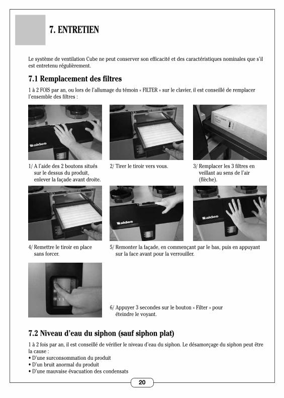
7.1 Remplacement des filtres1 à 2 FOIS par an, ou lors de l’allumage du témoin « FILTER » sur le clavier, il est conseillé de remplacer l’ensemble des filtres :
7.2 Niveau d’eau du siphon (sauf siphon plat)1 à 2 fois par an, il est conseillé de vérifier le niveau d’eau du siphon . Le désamorçage du siphon peut être la cause :•D’unesurconsommationduproduit•D’unbruitanormalduproduit•D’unemauvaiseévacuationdescondensats
2/ Tirer le tiroir vers vous .
5/ Remonter la façade, en commençant par le bas, puis en appuyant sur la face avant pour la verrouiller .
3/ Remplacer les 3 filtres en veillant au sens de l’air (flèche) .
1/ A l’aide des 2 boutons situés sur le dessus du produit, enlever la façade avant droite .
4/ Remettre le tiroir en place sans forcer .
6/ Appuyer 3 secondes sur le bouton « Filter » pour éteindre le voyant .
21
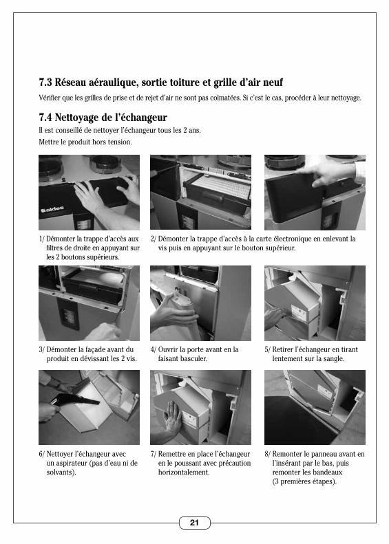
7.3 Réseau aéraulique, sortie toiture et grille d’air neufVérifier que les grilles de prise et de rejet d’air ne sont pas colmatées . Si c’est le cas, procéder à leur nettoyage .
7.4 Nettoyage de l’échangeurIl est conseillé de nettoyer l’échangeur tous les 2 ans .
Mettre le produit hors tension .
2/ Démonter la trappe d’accès à la carte électronique en enlevant la vis puis en appuyant sur le bouton supérieur .
4/ Ouvrir la porte avant en la faisant basculer .
5/ Retirer l’échangeur en tirant lentement sur la sangle .
1/ Démonter la trappe d’accès aux filtres de droite en appuyant sur les 2 boutons supérieurs .
3/ Démonter la façade avant du produit en dévissant les 2 vis .
7/ Remettre en place l’échangeur en le poussant avec précaution horizontalement.
8/Remonterlepanneauavantenl’insérant par le bas, puis remonter les bandeaux (3 premières étapes) .
6/ Nettoyer l’échangeur avec un aspirateur (pas d’eau ni de solvants) .
22
8. ANOMALIES DE FONCTIONNEMENT
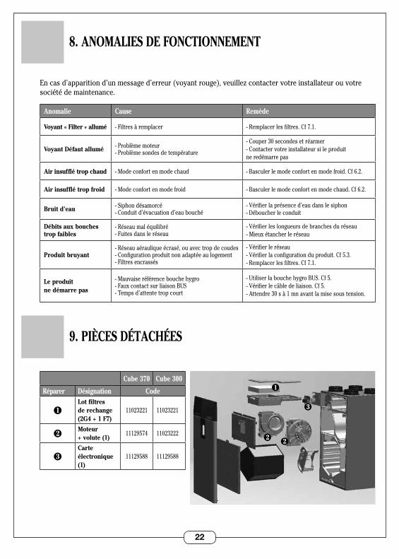
Encasd’apparitiond’unmessaged’erreur(voyantrouge),veuillezcontactervotreinstallateurouvotresociété de maintenance .
Anomalie Cause Remède
Voyant « Filter » allumé - Filtres à remplacer - Remplacer les filtres . Cf 7 .1 .
Voyant Défaut allumé - Problème moteur- Problème sondes de température
- Couper 30 secondes et réarmer - Contacter votre installateur si le produit ne redémarre pas
Air insufflé trop chaud - Mode confort en mode chaud - Basculer le mode confort en mode froid . Cf 6 .2 .
Air insufflé trop froid - Mode confort en mode froid - Basculer le mode confort en mode chaud . Cf 6 .2 .
Bruit d’eau - Siphon désamorcé- Conduit d’évacuation d’eau bouché
- Vérifier la présence d’eau dans le siphon- Déboucher le conduit
Débits aux bouches trop faibles
- Réseau mal équilibré- Fuites dans le réseau
- Vérifier les longueurs de branches du réseau- Mieux étancher le réseau
Produit bruyant- Réseau aéraulique écrasé, ou avec trop de coudes- Configuration produit non adaptée au logement- Filtres encrassés
- Vérifier le réseau- Vérifier la configuration du produit . Cf 5 .3 .- Remplacer les filtres . Cf 7 .1 .
Le produit ne démarre pas
- Mauvaise référence bouche hygro- Faux contact sur liaison BUS- Temps d’attente trop court
- Utiliser la bouche hygro BUS . Cf 5 .-Vérifierlecâbledeliaison.Cf5.- Attendre 30 s à 1 mn avant la mise sous tension .
9. PIÈCES DÉTACHÉES
3
Cube 370 Cube 300
Réparer Désignation Code
1Lot filtres de rechange (2G4 + 1 F7)
11023221 11023221
2Moteur + volute (1)
11129574 11023222
3Carte électronique (1)
11129588 11129588
3
2
1
2
23
10. GARANTIE
10.1 Conditions générales de garantieSe reporter aux conditions générales de vente sur le site www .aldes .fr .
Le système doit être installé par un professionnel qualifié suivant les règles de l’art, les normes en vigueur et les prescriptions de nos notices . Le système doit être utilisé normalement et régulièrement entretenu par un spécialiste .
10.2 Durée de la garantieLe produit bénéficie d’une garantie pièces (hors main d'œuvre) de 2 ans .
La garantie prend effet à compter de la date d’achat du produit, la facture faisant foi .
10.3 Conditions d’exclusion de la garantieSeront exclues de cette garantie, toute défaillance de l’installation liée à un non-respect des préconisations du fabricant, au non-respect des normes et réglementations en vigueur, ou à un manque d’entretien .
10.4 Service après-vente En cas de problème, merci de vous adresser à votre installateur ou à votre revendeur .
Ce produit ne doit pas être jeté avec les déchets ménagers . En fin de vie ou lors de son remplacement, il doit être remis à un revendeur ou un centre de collecte .
ALDES adhère à l’éco-organisme Eco Systemes www .ecosystemes .fr .

24 RC
S 95
6 50
6 82
8 -
Impr
imé
en F
ranc
e -
1102
9579
-B -
Ald
es s
e ré
serv
e le
dro
it d’
appo
rter à
ses
pro
duits
tout
es m
odifi
catio
ns li
ées
à l’é
volu
tion
de la
tech
niqu
e. L
e co
nten
u de
cet
te n
otic
e pe
ut ê
tre m
odifi
é sa
ns p
réav
is.
www.aldes.com
25
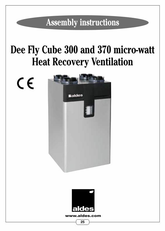
Assembly instructions
www.aldes.com
Dee Fly Cube 300 and 370 micro-watt Heat Recovery Ventilation
RC
S 95
6 50
6 82
8 -
Impr
imé
en F
ranc
e -
1102
9579
-B -
Ald
es s
e ré
serv
e le
dro
it d’
appo
rter à
ses
pro
duits
tout
es m
odifi
catio
ns li
ées
à l’é
volu
tion
de la
tech
niqu
e. L
e co
nten
u de
cet
te n
otic
e pe
ut ê
tre m
odifi
é sa
ns p
réav
is.

26
1. GENERAL INFORMATION . . . . . . . . . . . . . . . . . . . . . . . . . . . . . . . . . . . . . . . p.28 1 .1 Symbols . . . . . . . . . . . . . . . . . . . . . . . . . . . . . . . . . . . . . . . . . . . . . . . . . . . . . . 28 1 .2 General information . . . . . . . . . . . . . . . . . . . . . . . . . . . . . . . . . . . . . . . . . . . . 28 1 .3 Important recommendations and remarks . . . . . . . . . . . . . . . . . . . . . . . . . 28 1 .4 Safety instructions . . . . . . . . . . . . . . . . . . . . . . . . . . . . . . . . . . . . . . . . . . . . . 28 1.4.1Mechanicalhazards . . . . . . . . . . . . . . . . . . . . . . . . . . . . . . . . . . . . . . 28 1 .4 .2 Starting . . . . . . . . . . . . . . . . . . . . . . . . . . . . . . . . . . . . . . . . . . . . . . . . 28 1 .4 .3 Use . . . . . . . . . . . . . . . . . . . . . . . . . . . . . . . . . . . . . . . . . . . . . . . . . . . . 29 1 .4 .4 Maintenance . . . . . . . . . . . . . . . . . . . . . . . . . . . . . . . . . . . . . . . . . . . . 29 1 .4 .5 Transformation . . . . . . . . . . . . . . . . . . . . . . . . . . . . . . . . . . . . . . . . . 29 1 .4 .6 End of life . . . . . . . . . . . . . . . . . . . . . . . . . . . . . . . . . . . . . . . . . . . . . . 29 1 .5 Transport and storage . . . . . . . . . . . . . . . . . . . . . . . . . . . . . . . . . . . . . . . . . . 30 1 .6 Transport using a fork lift (with and without forks) . . . . . . . . . . . . . . . . . 30 1 .7 Manual transport . . . . . . . . . . . . . . . . . . . . . . . . . . . . . . . . . . . . . . . . . . . . . . 30
2. OPERATING PRINCIPLES . . . . . . . . . . . . . . . . . . . . . . . . . . . . . . . . . . . . . . . . . . 31 2 .1 Heat Recovery Ventilation System . . . . . . . . . . . . . . . . . . . . . . . . . . . . . . . . 31 2 .2 Positioning . . . . . . . . . . . . . . . . . . . . . . . . . . . . . . . . . . . . . . . . . . . . . . . . . . . . 31
3. DESCRIPTION . . . . . . . . . . . . . . . . . . . . . . . . . . . . . . . . . . . . . . . . . . . . . . . . . . . . 32 3 .1 Technical details . . . . . . . . . . . . . . . . . . . . . . . . . . . . . . . . . . . . . . . . . . . . . . 32 3 .2 Electrical consumption . . . . . . . . . . . . . . . . . . . . . . . . . . . . . . . . . . . . . . . . . 32 3 .3 Dimensions . . . . . . . . . . . . . . . . . . . . . . . . . . . . . . . . . . . . . . . . . . . . . . . . . . . 33
4. INSTALLATION . . . . . . . . . . . . . . . . . . . . . . . . . . . . . . . . . . . . . . . . . . . . . . . . . . . 34 4 .1 Installation site . . . . . . . . . . . . . . . . . . . . . . . . . . . . . . . . . . . . . . . . . . . . . . . . 34 4 .2 Type of installation . . . . . . . . . . . . . . . . . . . . . . . . . . . . . . . . . . . . . . . . . . . . 34 4 .3 Aeraulic connection . . . . . . . . . . . . . . . . . . . . . . . . . . . . . . . . . . . . . . . . . . . . 36 Aeraulic duct system . . . . . . . . . . . . . . . . . . . . . . . . . . . . . . . . . . . . . . . . 36 Type of roof cowl and fresh air grille to be used . . . . . . . . . . . . . . . . . 36 Circulation gap . . . . . . . . . . . . . . . . . . . . . . . . . . . . . . . . . . . . . . . . . . . . . . 37 Connection to the unit . . . . . . . . . . . . . . . . . . . . . . . . . . . . . . . . . . . . . . . 37 4 .4 Electrical connection . . . . . . . . . . . . . . . . . . . . . . . . . . . . . . . . . . . . . . . . . . . 38 Mains connection . . . . . . . . . . . . . . . . . . . . . . . . . . . . . . . . . . . . . . . . . . . 38 Option: Pushbutton kitchen/BOOST flow rate control . . . . . . . . . . . . 38 Specific connections for humidity-controlled operation . . . . . . . . . . . 39 4 .5 Condensation drainage . . . . . . . . . . . . . . . . . . . . . . . . . . . . . . . . . . . . . . . . . 40
CONTENTS
27
5. START UP . . . . . . . . . . . . . . . . . . . . . . . . . . . . . . . . . . . . . . . . . . . . . . . . . . . . . . . 41 5 .1 Important checks before starting . . . . . . . . . . . . . . . . . . . . . . . . . . . . . . . . . 41 5 .2 Access to the configuration key pad . . . . . . . . . . . . . . . . . . . . . . . . . . . . . . 41 5 .3 Factory settings . . . . . . . . . . . . . . . . . . . . . . . . . . . . . . . . . . . . . . . . . . . . . . . 42 5 .4 Adjusting the settings . . . . . . . . . . . . . . . . . . . . . . . . . . . . . . . . . . . . . . . . . . 42
6. USE . . . . . . . . . . . . . . . . . . . . . . . . . . . . . . . . . . . . . . . . . . . . . . . . . . . . . . . . . . . . 43 6 .1 Adjusting the ventilation flow rate . . . . . . . . . . . . . . . . . . . . . . . . . . . . . . . 43 6 .2 Choosing the comfort mode . . . . . . . . . . . . . . . . . . . . . . . . . . . . . . . . . . . . . 43
7. MAINTENANCE . . . . . . . . . . . . . . . . . . . . . . . . . . . . . . . . . . . . . . . . . . . . . . . . . . . 44 7 .1 Replacement of filters . . . . . . . . . . . . . . . . . . . . . . . . . . . . . . . . . . . . . . . . . . 44 7 .2 Water trap level . . . . . . . . . . . . . . . . . . . . . . . . . . . . . . . . . . . . . . . . . . . . . . . 44 7 .3 Aeraulic duct system, roof cowl and fresh air grille . . . . . . . . . . . . . . . . . 45 7 .4 Cleaning the exchanger . . . . . . . . . . . . . . . . . . . . . . . . . . . . . . . . . . . . . . . . . 45
8. TROUBLESHOOTING . . . . . . . . . . . . . . . . . . . . . . . . . . . . . . . . . . . . . . . . . . . . . 46
9. SPARE PARTS . . . . . . . . . . . . . . . . . . . . . . . . . . . . . . . . . . . . . . . . . . . . . . . . . . . . 46
10. GUARANTEE . . . . . . . . . . . . . . . . . . . . . . . . . . . . . . . . . . . . . . . . . . . . . . . . . . . . . 47 10 .1 General terms of the guarantee . . . . . . . . . . . . . . . . . . . . . . . . . . . . . . . . . 47 10 .2 Guarantee period . . . . . . . . . . . . . . . . . . . . . . . . . . . . . . . . . . . . . . . . . . . . . 47 10 .3 Guarantee exemptions . . . . . . . . . . . . . . . . . . . . . . . . . . . . . . . . . . . . . . . . . 47 10 .4 After sales service . . . . . . . . . . . . . . . . . . . . . . . . . . . . . . . . . . . . . . . . . . . . 47
28
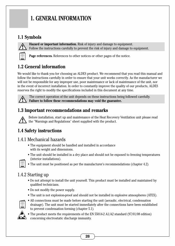
1.1 Symbols Hazard or important information. Risk of injury and damage to equipment . Follow the instructions carefully to prevent the risk of injury and damage to equipment .
Page references. References to other notices or other pages of the notice .
1.2 General informationWe would like to thank you for choosing an ALDES product . We recommend that you read this manual and follow the instructions carefully in order to ensure that your unit works correctly . As the manufacturer we will not be responsible for any improper use, poor maintenance or lack of maintenance of the unit, nor in the event of incorrect installation . In order to constantly improve the quality of our products, ALDES reserves the right to modify the specifications included in this document at any time .
The correct operation of the unit depends on these instructions being followed carefully . Failure to follow these recommendations may void the guarantee.
1.3 Important recommendations and remarks Before installation, start up and maintenance of the Heat Recovery Ventilation unit please read
the "Warnings and Regulations" sheet supplied with the product .
1.4 Safety instructions
1.4.1Mechanicalhazards •Theequipmentshouldbehandledandinstalledinaccordance
with its weight and dimensions .
•Theunitshouldbeinstalledinadryplaceandshouldnotbeexposedtofreezingtemperatures(interior installations) .
•Theunitmustbepositionedasperthemanufacturer'srecommendations(chapter4.2).
1 .4 .2 Starting up •Donotattempttoinstalltheunityourself.Thisproductmustbeinstalledandmaintainedby
qualified technicians .
•Donotmodifythepowersupply.
•Theunitisnotexplosion-proofandshouldnotbeinstalledinexplosiveatmospheres(ATEX).
•Allconnectionsmustbemadebeforestartingtheunit(aeraulic,electrical,condensationdrainage) . The unit must be started immediately after the connections have been established to prevent condensation forming (chapter 5 .1).
•TheproductmeetstherequirementsoftheEN55014-2A1/A2standard(97/01/08edition)concerning electrostatic discharge immunity .
1. GENERAL INFORMATION
29
1 .4 .3 Use •Callaprofessionalifamalfunctionoccurs.
•Tonotintroduceforeignbodiesintotheairinletandoutletgrilles.
•Nothingshouldblockthecirculationofair
•Donotclimbontheunit'schassis.
•Yourroomcomplieswithsafetystandards,donotmodifyit(ventilation,smokeducts,openingsetc .) without asking your installer first .
1 .4 .4 Maintenance •Donotattempttorepairyourunityourself.
•Thisunitcontainsnopartswhichcanberepairedbytheuser.Removinganyofthecoversmayexposeyoutohazardousvoltages.
•Cuttingtheelectricalpowerisnotsufficienttoremovethedangerofelectricalshocks(condensers) .
•Cutofftheelectricalpowerintheeventofabnormalnoises,smellsorthepresenceoffumesandcontact your installation technician .
•Cuttheelectricalpowerfromtheunitbeforeattemptingtocleanit.
•Donotuseanaggressivecleaningfluidorsolventstocleantheunit.
•Donotusepressurewatercleanerstocleantheairgrilles.Youriskdamaging the air exchanger and allowing water to come into contact with electrical circuits .
1 .4 .5 Modifications •Itisprohibitedtomodifytheunit.Replacementofcomponentsmustbeperformed
by a qualified professional using original spare parts supplied by the manufacturer .
1 .4 .6 End of life •Disconnectthepowerbeforedismantlingtheunit.
•Combustionofsomecomponentsmayreleasetoxicgases,donotincineratetheunit.
30
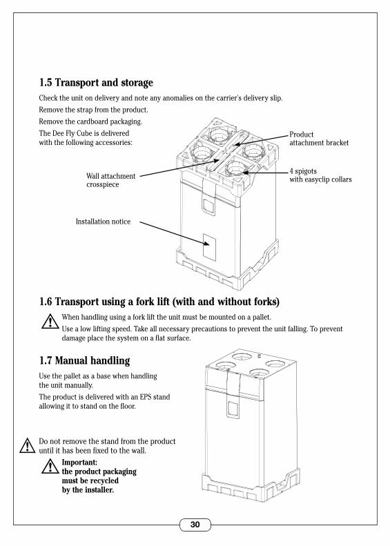
1.5 Transport and storageCheck the unit on delivery and note any anomalies on the carrier's delivery slip .
Remove the strap from the product .
Remove the cardboard packaging .
The Dee Fly Cube is delivered with the following accessories:
1.6 Transport using a fork lift (with and without forks) When handling using a fork lift the unit must be mounted on a pallet .
Use a low lifting speed . Take all necessary precautions to prevent the unit falling . To prevent damage place the system on a flat surface .
1.7 Manual handlingUse the pallet as a base when handling the unit manually .
The product is delivered with an EPS stand allowing it to stand on the floor .
Do not remove the stand from the product until it has been fixed to the wall . Important: the product packaging must be recycled by the installer.
VUE 3/4 AVANT BARQUETTE DESSUS
4 spigots with easyclip collars
Installation notice
Product attachment bracket
Wall attachment crosspiece
VUE 3/4 AVANT BARQUETTE DESSOUS
31
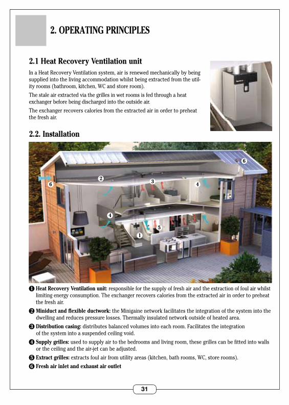
2.1 Heat Recovery Ventilation unit In a Heat Recovery Ventilation system, air is renewed mechanically by being supplied into the living accommodation whilst being extracted from the util-ity rooms (bathroom, kitchen, WC and store room) .
The stale air extracted via the grilles in wet rooms is fed through a heat exchanger before being discharged into the outside air .
The exchanger recovers calories from the extracted air in order to preheat the fresh air .
2.2. Installation
1 Heat Recovery Ventilation unit: responsible for the supply of fresh air and the extraction of foul air whilst limiting energy consumption . The exchanger recovers calories from the extracted air in order to preheat the fresh air .
2 Miniduct and flexible ductwork: the Minigaine network facilitates the integration of the system into the dwelling and reduces pressure losses . Thermally insulated network outside of heated area .
3 Distribution casing: distributes balanced volumes into each room . Facilitates the integration of the system into a suspended ceiling void .
4 Supply grilles: used to supply air to the bedrooms and living room, these grilles can be fitted into walls or the ceiling and the air-jet can be adjusted .
5 Extract grilles: extracts foul air from utility areas (kitchen, bath rooms, WC, store rooms) .
6 Fresh air inlet and exhaust air outlet
2. OPERATING PRINCIPLES
62
6
1
4
4
5
3
32
3.1 Technical details
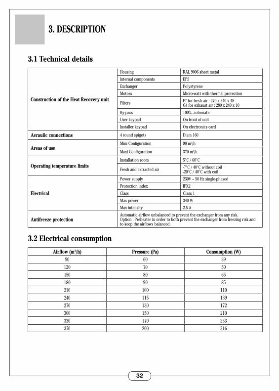
Construction of the Heat Recovery unit
Housing RAL9006sheetmetal
Internal components EPS
Exchanger Polystyrene
Motors Micro-watt with thermal protection
Filters F7forfreshair:270x240x48 G4forexhaustair:280x240x10
By-pass 100%, automatic
User keypad On front of unit
Installer keypad On electronics card
Aeraulic connections 4 round spigots Diam 160
Areas of useMini Configuration 90m3/h
Maxi Configuration 370 m3/h
Operating temperature limitsInstallation room 5°C / 60°C
Fresh and extracted air -7°C / 40°C without coil -20°C / 40°C with coil
Electrical
Power supply 230V–50Hzsingle-phased
Protection index IPX2
Class Class 1
Max power 340 W
Max intensity 2 .5 A
Antifreeze protectionAutomatic airflow unbalanced to prevent the exchanger from any risk . Option:Preheaterinordertobothpreventtheexchangerfromfreezingriskandto keep the airflows balanced .
3.2 Electrical consumption
Airflow (m3/h) Pressure (Pa) Consumption (W)90 60 39
120 70 50150 80 65180 90 85210 100 110240 115 139270 130 172300 150 210330 170 253370 200 316
3. DESCRIPTION
33
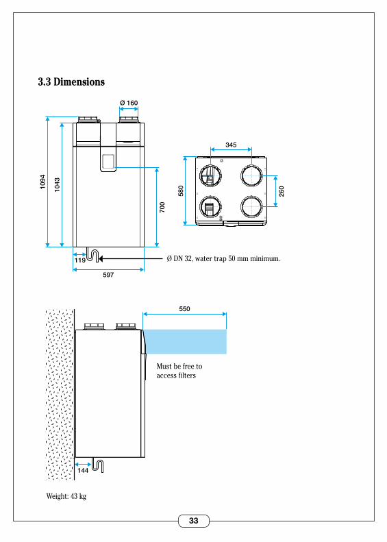
3.3 Dimensions
1094
1043
597
119
580
700
345
Ø 160
260
144
550
Ø DN 32, water trap 50 mm minimum .
Must be free toaccess filters
Weight: 43 kg
34
4. INSTALLATION
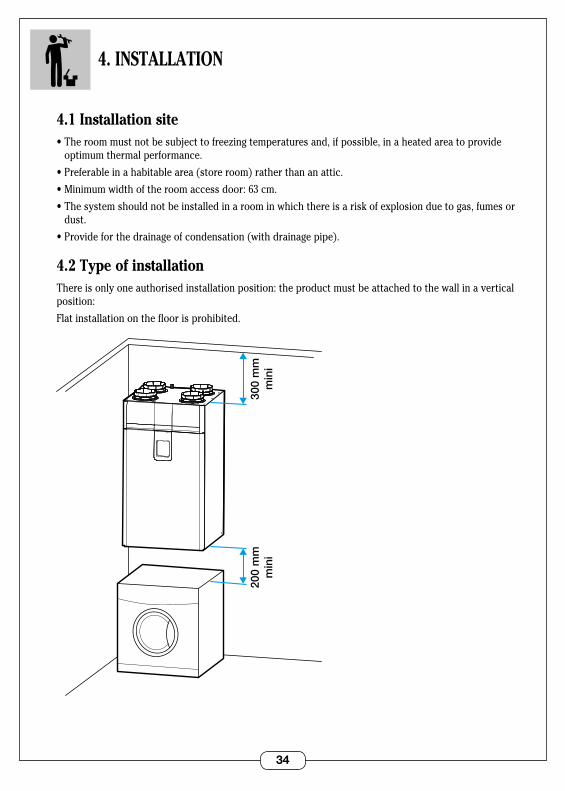
4.1 Installation site•Theroommustnotbesubjecttofreezingtemperaturesand,ifpossible,inaheatedareatoprovide
optimum thermal performance .
•Preferableinahabitablearea(storeroom)ratherthananattic.
•Minimumwidthoftheroomaccessdoor:63cm.
•Thesystemshouldnotbeinstalledinaroominwhichthereisariskofexplosionduetogas,fumesordust .
•Provideforthedrainageofcondensation(withdrainagepipe).
4.2 Type of installationThere is only one authorised installation position: the product must be attached to the wall in a vertical position:
Flat installation on the floor is prohibited .
200
mm
min
i30
0 m
mm
ini
35
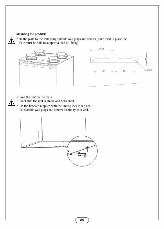
Mounting the product:
•Fixtheplatetothewallusingsuitablewallplugsandscrews(oncefixedinplacethe plate must be able to support a load of 120 kg) .
•Hangtheunitontheplate. Checkthattheunitisstableandhorizontal.
•Usethebracketsuppliedwiththeunittolockitinplace. Use suitable wall plugs and screws for the type of wall .
5,2
46
250 250
298,3
VUE ARRIERE SUPPORT MURAL
5,2
46
250 250
298,3
VUE ARRIERE SUPPORT MURAL
VUE 3/4 DESSOUS EQUERRE MURALE
VUE 3/4 DESSOUS EQUERRE MURALE
36
4.3 Aeraulic connections
Type of aeraulic duct systemThe product can be used with several types of ducts:
•Algaineflexibleducts.(useatleast50mmofinsulationwheninstalledinnon-heatedareas).
•Minigainerigidducts(onlyinheatedareas).
•Flexigainesemi-rigidducts(onlyinheatedareas).
Recommendations for fitting ducts: •Flexibleductsmustbesuspended. •Avoidunnecessarybends. •Makesuretheductsarenotcrushed.
Type of roof cowl and fresh air grille to be used To minimise pressure losses the product must be used as follows:
Extraction of foul air:•Eitherviaaroofcowlwithdiameter160,typeSTS•Orviaanexternalwallgrille,typeAWA251300x300.
Fresh air intake:•Externalwallgrille,typeAWA251300x300.
Thefreshairintakeandfoulairoutletmustbeinstalledon2differentwallsectionsoratleast8metresapart to prevent recirculation .
The grille must be positioned so that it does not get wet or become blocked . Position it carefully (away from chimneys, car parking)
The roof cowl and fresh air intake must be connected to the unit using ducts which are 160 mm in diameter . It is not recommended that the fresh air intake be positioned on the roof (risk of ingestion of water or snow into the Heat Recovery unit) .
37
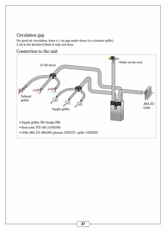
Circulation gapFor good air circulation, leave a 1 cm gap under doors (or a transfer grille), 2 cm in the kitchen if there is only one door .
Connection to the unit
Supply grilles
•Supplygrilles:BIOdesignD80
•Roofcowl:STS160(11030108)
•GrilleAWA251300x300(plenum11053757+grille11052039)
Exhaust grilles
Ø 160 ductsOutlet on the roof
AWA 251 Grille
38
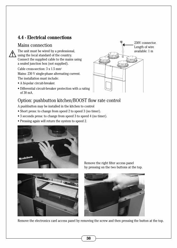
4.4 - Electrical connections
Mains connectionThe unit must be wired by a professional, using the local standard of the country . Connect the supplied cable to the mains using a sealed junction box (not supplied) .
Cable cross-section: 3 x 1 .5 mm2
Mains: 230 V single-phase alternating current .The installation must include:•Abi-polarcircuit-breaker.
•Differentialcircuit-breakerprotectionwitharating of 30 mA .
Option: pushbutton kitchen/BOOST flow rate controlA pushbutton may be installed in the kitchen to control •Shortpress:tochangefromspeed2tospeed3(notimer).•3secondspress:tochangefromspeed3tospeed4(notimer).•Pressingagainwillreturnthesystemtospeed2.
Remove the right filter access panel by pressing on the two buttons at the top .
Remove the electronics card access panel by removing the screw and then pressing the button at the top .
VUE 3/4 DESSUS SORTIE CORDON
230V connector . Length of wire available: 1 m
39
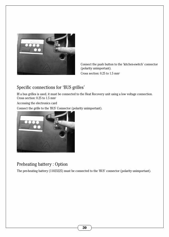
Connect the push button to the ‘kitchen-switch’ connector (polarity unimportant) .
Cross section: 0 .25 to 1 .5 mm2
Specific connections for ‘BUS grilles’Iff a bus grilles is used, it must be connected to the Heat Recovery unit using a low voltage connection . Cross section: 0 .25 to 1 .5 mm2
Accessing the electronics card
Connect the grille to the 'BUS' Connector (polarity unimportant) .
Preheating battery : OptionThe pre-heating battery (11023225) must be connected to the ‘BUS’ connector (polarity unimportant) .

40
4.5 Condensation drainageBefore being started the product must be connected to a PVC diameter 32 drainage pipe, through a water trap:
•Useawatertrapwithatleasta50mmtank,oraflatwatertrap.
•Immersethewatertrapinwaterbeforeconnectingtotheproduct(exceptflatwatertrap).
•Beawarethereisnoairleakagebetweenwatertrapandmachine.
•Versionwithwaterlessflattrap.•Versionwithwatertrap

41
5. START UP
5.1 Important checks before startingCheck the following before turning on the power:
•Checkthatthepowercableisnotdamaged
•Checkthepowersupplyvoltageandthecorrectpositionoftheneutralpole.
•Theunitmustbeearthed.
•Checkthatthewiresofconnectorsarethecorrectcolour.
•Makesurethataeraulicductsarecorrectlyconnected.
•Makesurethatthecondensationdrainiscorrectlyconnectedtoadrainagepipethroughawatertrap.
5.2 Access to the configuration key pad
Remove the right filter access panel by pressing on the two buttons at the top .
Remove the electronics card access panel by removing the screw and then pressing the button at the top .
42
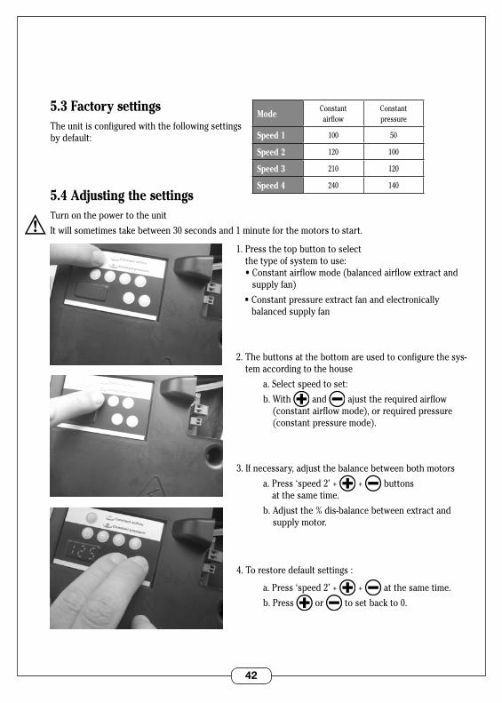
5.3 Factory settingsThe unit is configured with the following settings by default:
5.4 Adjusting the settingsTurn on the power to the unit
It will sometimes take between 30 seconds and 1 minute for the motors to start .
1 . Press the top button to select the type of system to use: •Constantairflowmode(balancedairflowextractand
supply fan)
•Constantpressureextractfanandelectronically balanced supply fan
2 . The buttons at the bottom are used to configure the sys-tem according to the house
a . Select speed to set:
b . With and ajust the required airflow (constant airflow mode), or required pressure (constant pressure mode) .
3 . If necessary, adjust the balance between both motors
a.Press‘speed2’+ + buttons at the same time .
b . Adjust the % dis-balance between extract and supply motor .
4 . To restore default settings :
a . Press ‘speed 2’+ + at the same time .
b . Press or to set back to 0 .
ModeConstantairflow
Constantpressure
Speed 1 100 50
Speed 2 120 100
Speed 3 210 120
Speed 4 240 140
43
6. USE
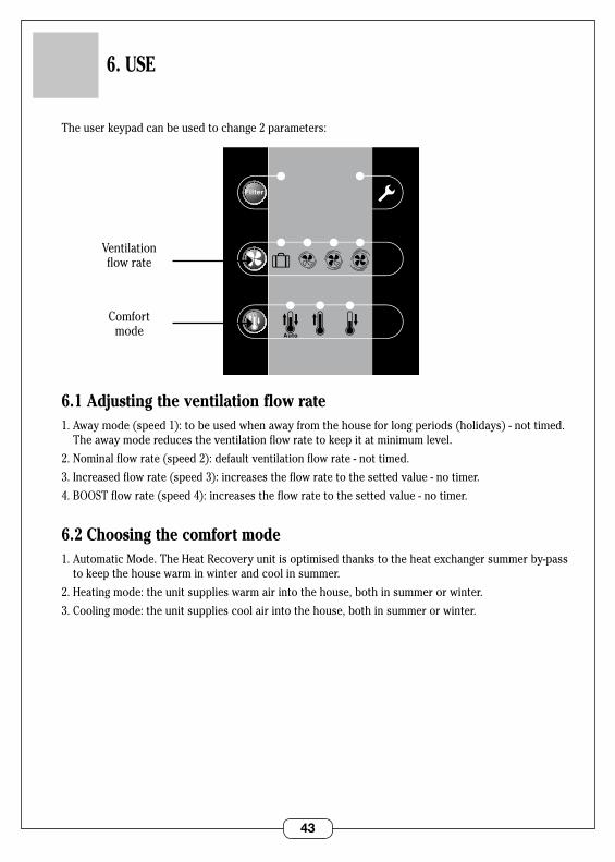
The user keypad can be used to change 2 parameters:
6.1 Adjusting the ventilation flow rate1 . Away mode (speed 1): to be used when away from the house for long periods (holidays) - not timed .
The away mode reduces the ventilation flow rate to keep it at minimum level .
2 . Nominal flow rate (speed 2): default ventilation flow rate - not timed .
3 . Increased flow rate (speed 3): increases the flow rate to the setted value - no timer .
4 . BOOST flow rate (speed 4): increases the flow rate to the setted value - no timer .
6.2 Choosing the comfort mode1 . Automatic Mode . The Heat Recovery unit is optimised thanks to the heat exchanger summer by-pass
to keep the house warm in winter and cool in summer .
2 . Heating mode: the unit supplies warm air into the house, both in summer or winter .
3 . Cooling mode: the unit supplies cool air into the house, both in summer or winter .
0
SDBType Logement
CellierWC
1 2 3 4 5/6/7
Hygro
Auto
0
SDBType Logement
CellierWC
1 2 3 4 5/6/7
Hygro
Auto
Ventilation flow rate
Comfort mode

44
7. MAINTENANCE
The Dee Fly HRV ventilation system can only remain efficient and provide its rated capacity if it is regularly maintained .
7.1 Replacement of filtersWe recommend that all filters be replaced ONCE or TWICE a year or when the "FILTER" light is lit on the keypad .
7.2 Water trap level (except with flat water trap)We recommend you check the water trap level once or twice per year . Malfunction of the water trap can cause:•Theproducttoover-consumeelectricity•Theproducttomakeunusualnoises•Poordrainageofcondensation
2/ Pull the drawer towards you .
5/ Replace the cover starting from the bottom, push on the front to snap it into place .
3/ Replace the 2 filters and check the direction of flow (arrow) .
1/ Using the 2 buttons located on top of the product, remove the front right cover .
4/ Put the drawer back in place without forcing it .
6/ Press and hold the “Filter” button for 3 seconds to turn off the light .
45
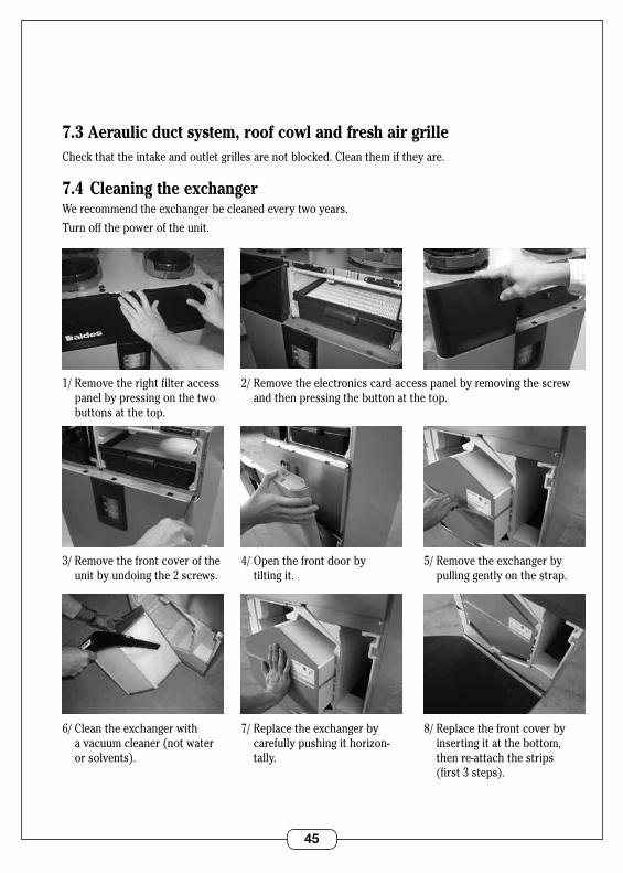
7.3 Aeraulic duct system, roof cowl and fresh air grilleCheck that the intake and outlet grilles are not blocked . Clean them if they are .
7.4 Cleaning the exchangerWe recommend the exchanger be cleaned every two years .
Turn off the power of the unit .
2/ Remove the electronics card access panel by removing the screw and then pressing the button at the top .
4/ Open the front door by tilting it .
5/ Remove the exchanger by pulling gently on the strap .
1/ Remove the right filter access panel by pressing on the two buttons at the top .
3/ Remove the front cover of the unit by undoing the 2 screws .
7/ Replace the exchanger by carefullypushingithorizon-tally .
8/Replacethefrontcoverbyinserting it at the bottom, then re-attach the strips (first 3 steps) .
6/ Clean the exchanger with a vacuum cleaner (not water or solvents) .
46
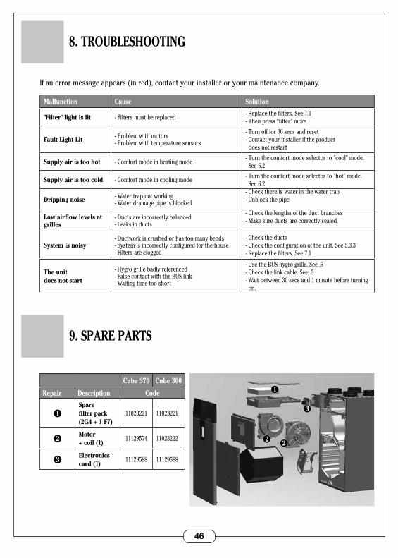
Cube 370 Cube 300
Repair Description Code
1Spare filter pack (2G4 + 1 F7)
11023221 11023221
2Motor + coil (1)
11129574 11023222
3Electronics card (1)
11129588 11129588
3
2
1
2
8. TROUBLESHOOTING
If an error message appears (in red), contact your installer or your maintenance company .
Malfunction Cause Solution
"Filter" light is lit - Filters must be replaced- Replace the filters . See 7 .1 - Then press “filter” more
Fault Light Lit - Problem with motors- Problem with temperature sensors
- Turn off for 30 secs and reset - Contact your installer if the product does not restart
Supply air is too hot - Comfort mode in heating mode- Turn the comfort mode selector to "cool" mode .
See 6 .2
Supply air is too cold - Comfort mode in cooling mode- Turn the comfort mode selector to "hot" mode .
See 6 .2
Dripping noise - Water trap not working- Water drainage pipe is blocked
- Check there is water in the water trap- Unblock the pipe
Low airflow levels at grilles
- Ducts are incorrectly balanced- Leaks in ducts
- Check the lengths of the duct branches- Make sure ducts are correctly sealed
System is noisy- Ductwork is crushed or has too many bends- System is incorrectly configured for the house- Filters are clogged
- Check the ducts- Check the configuration of the unit . See 5 .3 .3- Replace the filters . See 7 .1
The unit does not start
- Hygro grille badly referenced- False contact with the BUS link- Waiting time too short
- Use the BUS hygro grille . See .5- Check the link cable . See .5- Wait between 30 secs and 1 minute before turning
on .
9. SPARE PARTS
47
10. GUARANTEE
10.1 General terms of the guaranteeRead the general conditions of sale at our website www .aldes .fr .
The system must be installed by a qualified professional in compliance with all regulations, standards and recommendations contained in notices . The system must be used normally and regularly and be maintained by a specialist .
10.2 Guarantee periodThe product is guaranteed for 2 years . The guarantee only covers parts replacement but excludes labour .
The guarantee takes effect from the date the product is purchased from the store, with the invoice being proof of this date .
10.3 Guarantee exemptionsAll installation defects resulting from a failure to comply with the manufacturer's recommendations, a failure to comply with current regulations, and lack of maintenance will not be covered by the guarantee .
10.4 After-sales service In the event of a problem, please contact your fitter or re-seller .
This product must not be disposed of with household waste . At the end of its life, or when it is replaced, it must be taken to a waste collection centre or returned to a reseller .
ALDES is a member of the eco-organisation Eco Systemes www .ecosystemes .fr

48 RC
S 9
56 5
06 8
28 -
Prin
ted
in F
ranc
e -
1102
9579
-B -
ALD
ES r
eser
ves
the
right
to
mod
ify a
ny t
echn
ical
info
rmat
ion
cont
aine
d he
rein
. The
con
tent
s of
the
se in
stru
ctio
ns m
ay b
e m
odifi
ed w
ithou
t no
tice.
www.aldes.com
49
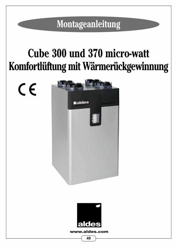
Montageanleitung
www.aldes.com
Cube 300 und 370 micro-watt Komfortlüftung mit Wärmerückgewinnung
RC
S 9
56 5
06 8
28 -
Prin
ted
in F
ranc
e -
1102
9579
-B -
ALD
ES r
eser
ves
the
right
to
mod
ify a
ny t
echn
ical
info
rmat
ion
cont
aine
d he
rein
. The
con
tent
s of
the
se in
stru
ctio
ns m
ay b
e m
odifi
ed w
ithou
t no
tice.
50
1. ALLGEMEINES . . . . . . . . . . . . . . . . . . . . . . . . . . . . . . . . . . . . . . . . . . . . . . . . . S.52 1 .1 Symbole . . . . . . . . . . . . . . . . . . . . . . . . . . . . . . . . . . . . . . . . . . . . . . . . . . . . . . 52 1 .2 Allgemeine Informationen . . . . . . . . . . . . . . . . . . . . . . . . . . . . . . . . . . . . . . . 52 1 .3 Wichtige Empfehlungen und Bemerkungen . . . . . . . . . . . . . . . . . . . . . . . . 52 1 .4 Sicherheitsvorschriften . . . . . . . . . . . . . . . . . . . . . . . . . . . . . . . . . . . . . . . . . 52 1 .4 .1 Mechanische Gefahren . . . . . . . . . . . . . . . . . . . . . . . . . . . . . . . . . . . 52 1 .4 .2 Inbetriebnahme . . . . . . . . . . . . . . . . . . . . . . . . . . . . . . . . . . . . . . . . . 52 1 .4 .3 Betrieb . . . . . . . . . . . . . . . . . . . . . . . . . . . . . . . . . . . . . . . . . . . . . . . . . 53 1 .4 .4 Instandhaltung . . . . . . . . . . . . . . . . . . . . . . . . . . . . . . . . . . . . . . . . . . 53 1 .4 .5 Änderungen . . . . . . . . . . . . . . . . . . . . . . . . . . . . . . . . . . . . . . . . . . . . 53 1 .4 .6 Lebensende . . . . . . . . . . . . . . . . . . . . . . . . . . . . . . . . . . . . . . . . . . . . . 53 1 .5 Transport und Lagerung . . . . . . . . . . . . . . . . . . . . . . . . . . . . . . . . . . . . . . . . 54 1 .6 Transport mit einem Gabelstapler (mit und ohne Gabeln) . . . . . . . . . . . 54 1 .7 Manueller Transport . . . . . . . . . . . . . . . . . . . . . . . . . . . . . . . . . . . . . . . . . . . 54
2. FUNKTIONSPRINZIPIEN . . . . . . . . . . . . . . . . . . . . . . . . . . . . . . . . . . . . . . . . . . . 55 2 .1 Komfortlüfter mit Wärmerückgewinnung . . . . . . . . . . . . . . . . . . . . . . . . . . 55 2 .2 Aufstellung . . . . . . . . . . . . . . . . . . . . . . . . . . . . . . . . . . . . . . . . . . . . . . . . . . . . 55
3. BESCHREIBUNG . . . . . . . . . . . . . . . . . . . . . . . . . . . . . . . . . . . . . . . . . . . . . . . . . . 56 3 .1 Technische Daten . . . . . . . . . . . . . . . . . . . . . . . . . . . . . . . . . . . . . . . . . . . . . . 56 3 .2 Stromverbrauch . . . . . . . . . . . . . . . . . . . . . . . . . . . . . . . . . . . . . . . . . . . . . . . 56 3 .3 Abmessungen . . . . . . . . . . . . . . . . . . . . . . . . . . . . . . . . . . . . . . . . . . . . . . . . . 57
4. INSTALLATION . . . . . . . . . . . . . . . . . . . . . . . . . . . . . . . . . . . . . . . . . . . . . . . . . . . 58 4 .1 Aufstellungsort . . . . . . . . . . . . . . . . . . . . . . . . . . . . . . . . . . . . . . . . . . . . . . . . 58 4 .2 Installationsart . . . . . . . . . . . . . . . . . . . . . . . . . . . . . . . . . . . . . . . . . . . . . . . . 58 4 .3 Luftanschluss . . . . . . . . . . . . . . . . . . . . . . . . . . . . . . . . . . . . . . . . . . . . . . . . . 60 Luftführungssystem . . . . . . . . . . . . . . . . . . . . . . . . . . . . . . . . . . . . . . . . . 60 Zu verwendende(s) Abdeckhaube und Frischluftgitter . . . . . . . . . . . . 60 Zirkulationsfreiraum . . . . . . . . . . . . . . . . . . . . . . . . . . . . . . . . . . . . . . . . . 61 Anschluss an die Anlage . . . . . . . . . . . . . . . . . . . . . . . . . . . . . . . . . . . . . . 61 4 .4 Stromanschluss . . . . . . . . . . . . . . . . . . . . . . . . . . . . . . . . . . . . . . . . . . . . . . . 62 Netzanschluss . . . . . . . . . . . . . . . . . . . . . . . . . . . . . . . . . . . . . . . . . . . . . . 62 Option: Druckknopf Küche/BOOST Volumenstromregelung . . . . . . . . 62 SpezialanschlüssefürdenBetriebmitLuftfeuchteregelung . . . . . . . . 63 4 .5 Kondensatableitung . . . . . . . . . . . . . . . . . . . . . . . . . . . . . . . . . . . . . . . . . . . . 64
INHALT
51
5. ERSTINBETRIEBNAHME . . . . . . . . . . . . . . . . . . . . . . . . . . . . . . . . . . . . . . . . . . . 65 5 .1 Wichtige Kontrollen vor der Inbetriebnahme . . . . . . . . . . . . . . . . . . . . . . 65 5 .2 Zugriff auf die Konfigurationstastatur . . . . . . . . . . . . . . . . . . . . . . . . . . . . . 65 5 .3 Werkseinstellungen . . . . . . . . . . . . . . . . . . . . . . . . . . . . . . . . . . . . . . . . . . . . 66 5 .4 Einstellungen anpassen . . . . . . . . . . . . . . . . . . . . . . . . . . . . . . . . . . . . . . . . . 66
6. BETRIEB . . . . . . . . . . . . . . . . . . . . . . . . . . . . . . . . . . . . . . . . . . . . . . . . . . . . . . . . 67 6 .1 Den Luftvolumenstrom anpassen . . . . . . . . . . . . . . . . . . . . . . . . . . . . . . . . 67 6 .2 Auswahl des Komfort-Modus . . . . . . . . . . . . . . . . . . . . . . . . . . . . . . . . . . . . 67
7. INSTANDHALTUNG . . . . . . . . . . . . . . . . . . . . . . . . . . . . . . . . . . . . . . . . . . . . . . . 68 7 .1 Filtertausch . . . . . . . . . . . . . . . . . . . . . . . . . . . . . . . . . . . . . . . . . . . . . . . . . . . 68 7 .2 Siphonniveau . . . . . . . . . . . . . . . . . . . . . . . . . . . . . . . . . . . . . . . . . . . . . . . . . . 68 7 .3 Luftleitung, Abdeckhaube und Frischluftgitter . . . . . . . . . . . . . . . . . . . . . 69 7 .4 Reinigen des Wärmetauschers . . . . . . . . . . . . . . . . . . . . . . . . . . . . . . . . . . . 69
8. FEHLERSUCHE . . . . . . . . . . . . . . . . . . . . . . . . . . . . . . . . . . . . . . . . . . . . . . . . . . . 70
9. ERSATZTEILE . . . . . . . . . . . . . . . . . . . . . . . . . . . . . . . . . . . . . . . . . . . . . . . . . . . . 70
10. GARANTIE . . . . . . . . . . . . . . . . . . . . . . . . . . . . . . . . . . . . . . . . . . . . . . . . . . . . . . . 71 10 .1 Allgemeine Garantiebestimmungen . . . . . . . . . . . . . . . . . . . . . . . . . . . . . . 71 10.2Garantielaufzeit . . . . . . . . . . . . . . . . . . . . . . . . . . . . . . . . . . . . . . . . . . . . . . . 71 10 .3 Ausnahmebestimmungen . . . . . . . . . . . . . . . . . . . . . . . . . . . . . . . . . . . . . . 71 10 .4 Kundendienst . . . . . . . . . . . . . . . . . . . . . . . . . . . . . . . . . . . . . . . . . . . . . . . . 71
52
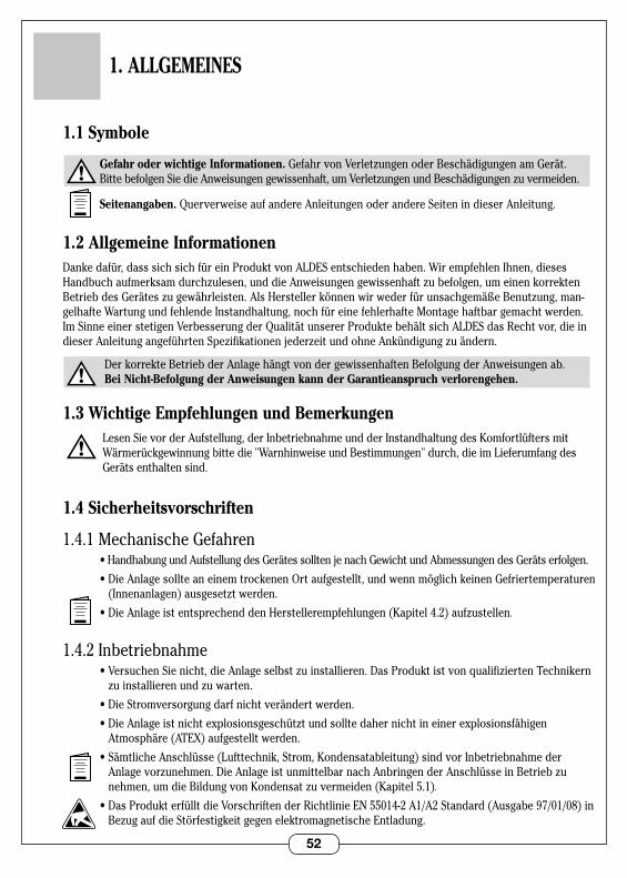
1.1 Symbole
Gefahr oder wichtige Informationen.GefahrvonVerletzungenoderBeschädigungenamGerät. BittebefolgenSiedieAnweisungengewissenhaft,umVerletzungenundBeschädigungenzuvermeiden.
Seitenangaben. Querverweise auf andere Anleitungen oder andere Seiten in dieser Anleitung .
1.2 Allgemeine InformationenDanke dafür, dass sich sich für ein Produkt von ALDES entschieden haben . Wir empfehlen Ihnen, dieses Handbuchaufmerksamdurchzulesen,unddieAnweisungengewissenhaftzubefolgen,umeinenkorrektenBetriebdesGeräteszugewährleisten.AlsHerstellerkönnenwirwederfürunsachgemäßeBenutzung,man-gelhafte Wartung und fehlende Instandhaltung, noch für eine fehlerhafte Montage haftbar gemacht werden . Im Sinne einer stetigen Verbesserung der Qualität unserer Produkte behält sich ALDES das Recht vor, die in dieserAnleitungangeführtenSpezifikationenjederzeitundohneAnkündigungzuändern.
Der korrekte Betrieb der Anlage hängt von der gewissenhaften Befolgung der Anweisungen ab . Bei Nicht-Befolgung der Anweisungen kann der Garantieanspruch verlorengehen.
1.3 Wichtige Empfehlungen und Bemerkungen Lesen Sie vor der Aufstellung, der Inbetriebnahme und der Instandhaltung des Komfortlüfters mit
Wärmerückgewinnung bitte die "Warnhinweise und Bestimmungen" durch, die im Lieferumfang des Geräts enthalten sind .
1.4 Sicherheitsvorschriften
1 .4 .1 Mechanische Gefahren •HandhabungundAufstellungdesGerätessolltenjenachGewichtundAbmessungendesGerätserfolgen.
•DieAnlagesollteaneinemtrockenenOrtaufgestellt,undwennmöglichkeinenGefriertemperaturen(Innenanlagen)ausgesetztwerden.
•DieAnlageistentsprechenddenHerstellerempfehlungen(Kapitel4.2)aufzustellen.
1 .4 .2 Inbetriebnahme •VersuchenSienicht,dieAnlageselbstzuinstallieren.DasProduktistvonqualifiziertenTechnikern
zuinstallierenundzuwarten.
•DieStromversorgungdarfnichtverändertwerden.
•DieAnlageistnichtexplosionsgeschütztundsolltedahernichtineinerexplosionsfähigenAtmosphäre (ATEX) aufgestellt werden .
•SämtlicheAnschlüsse(Lufttechnik,Strom,Kondensatableitung)sindvorInbetriebnahmederAnlagevorzunehmen.DieAnlageistunmittelbarnachAnbringenderAnschlüsseinBetriebzunehmen,umdieBildungvonKondensatzuvermeiden(Kapitel5.1).
•DasProdukterfülltdieVorschriftenderRichtlinieEN55014-2A1/A2Standard(Ausgabe97/01/08)inBezugaufdieStörfestigkeitgegenelektromagnetischeEntladung.
1. ALLGEMEINES
53
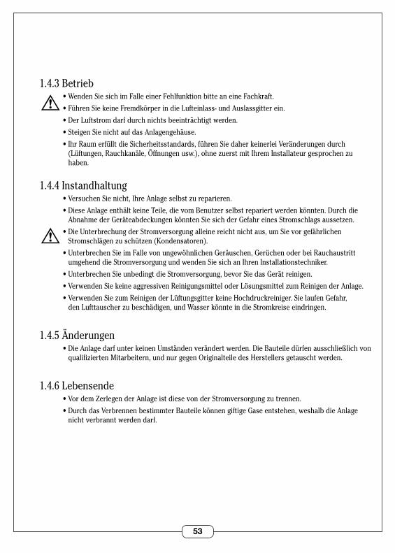
1 .4 .3 Betrieb •WendenSiesichimFalleeinerFehlfunktionbitteaneineFachkraft.
•FührenSiekeineFremdkörperindieLufteinlass-undAuslassgitterein.
•DerLuftstromdarfdurchnichtsbeeinträchtigtwerden.
•SteigenSienichtaufdasAnlagengehäuse.
•IhrRaumerfülltdieSicherheitsstandards,führenSiedaherkeinerleiVeränderungendurch(Lüftungen,Rauchkanäle,Öffnungenusw.),ohnezuerstmitIhremInstallateurgesprochenzuhaben .
1 .4 .4 Instandhaltung •VersuchenSienicht,IhreAnlageselbstzureparieren.
•DieseAnlageenthältkeineTeile,dievomBenutzerselbstrepariertwerdenkönnten.DurchdieAbnahmederGeräteabdeckungenkönntenSiesichderGefahreinesStromschlagsaussetzen.
•DieUnterbrechungderStromversorgungalleinereichtnichtaus,umSievorgefährlichenStromschlägenzuschützen(Kondensatoren).
•UnterbrechenSieimFallevonungewöhnlichenGeräuschen,GerüchenoderbeiRauchaustrittumgehend die Stromversorgung und wenden Sie sich an Ihren Installationstechniker .
•UnterbrechenSieunbedingtdieStromversorgung,bevorSiedasGerätreinigen.
•VerwendenSiekeineaggressivenReinigungsmitteloderLösungsmittelzumReinigenderAnlage.
•VerwendenSiezumReinigenderLüftungsgitterkeineHochdruckreiniger.SielaufenGefahr, denLufttauscherzubeschädigen,undWasserkönnteindieStromkreiseeindringen.
1 .4 .5 Änderungen •DieAnlagedarfunterkeinenUmständenverändertwerden.DieBauteiledürfenausschließlichvon
qualifiziertenMitarbeitern,undnurgegenOriginalteiledesHerstellersgetauschtwerden.
1 .4 .6 Lebensende •VordemZerlegenderAnlageistdiesevonderStromversorgungzutrennen.
•DurchdasVerbrennenbestimmterBauteilekönnengiftigeGaseentstehen,weshalbdieAnlagenicht verbrannt werden darf .
54
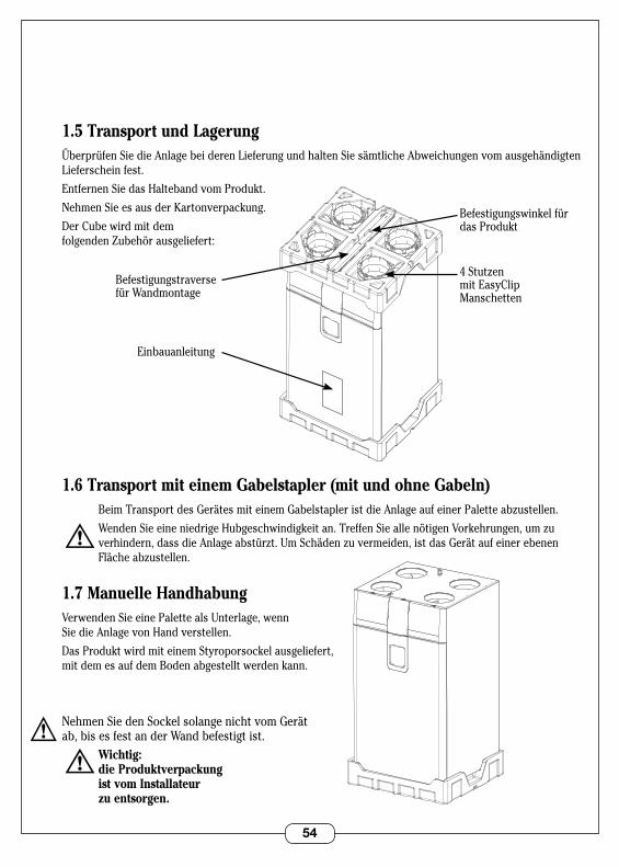
1.5 Transport und LagerungÜberprüfen Sie die Anlage bei deren Lieferung und halten Sie sämtliche Abweichungen vom ausgehändigten Lieferschein fest .
Entfernen Sie das Halteband vom Produkt .
Nehmen Sie es aus der Kartonverpackung .
Der Cube wird mit dem folgendenZubehörausgeliefert:
1.6 Transport mit einem Gabelstapler (mit und ohne Gabeln) BeimTransportdesGerätesmiteinemGabelstapleristdieAnlageaufeinerPaletteabzustellen.
WendenSieeineniedrigeHubgeschwindigkeitan.TreffenSieallenötigenVorkehrungen,umzuverhindern,dassdieAnlageabstürzt.UmSchädenzuvermeiden,istdasGerätaufeinerebenenFlächeabzustellen.
1.7 Manuelle HandhabungVerwenden Sie eine Palette als Unterlage, wenn Sie die Anlage von Hand verstellen .
Das Produkt wird mit einem Styroporsockel ausgeliefert, mit dem es auf dem Boden abgestellt werden kann .
Nehmen Sie den Sockel solange nicht vom Gerät ab, bis es fest an der Wand befestigt ist . Wichtig: die Produktverpackung ist vom Installateur zu entsorgen.
VUE 3/4 AVANT BARQUETTE DESSUS
4Stutzen mit EasyClip Manschetten
Einbauanleitung
Befestigungswinkel für das Produkt
Befestigungstraverse für Wandmontage
VUE 3/4 AVANT BARQUETTE DESSOUS
55
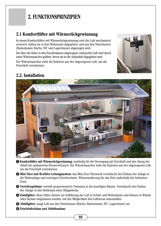
2.1 Komfortlüfter mit Wärmerückgewinnung In einem Komfortlüfter mit Wärmerückgewinnung wird die Luft mechanisch erneuert,indemsieindenWohnraumabgegeben,undausdenNutzräumen(Badezimmer,Küche,WCundLagerräume)abgezogenwird.
DieüberdieGitterindenFeuchträumenabgezogenevebrauchteLuftwirddurcheinenWärmetauschergeführt,bevorsieindieAußenluftabgegebenwird.
DerWärmetauscherziehtdieKalorienausderabgezogenenLuft,umdieFrischluftvorzuheizen.
2.2. Installation
1 Komfortlüfter mit Wärmerückgewinnung: zuständigfürdieVersorgungmitFrischluftunddenAbzugderAbluft bei optimiertem Stromverbrauch .DerWärmetauscherziehtdieKalorienausderabgezogenenLuft,umdieFrischluftvorzuheizen.
2 Mini Duct und flexibles Leitungssystem: dasMiniDuctNetzwerkvereinfachtdenEinbauderAnlageindieWohnanlageundverringertDruckverluste.WärmeisolierungfürdasNetzaußerhalbderbeheiztenZone .
3 Verteilergehäuse: verteilt proportionierte Volumina in die jeweiligen Räume . Vereinfacht den Einbau der Anlage in den Hohlraum einer Hängedecke .
4 Zuluftgitter: dieseGitterdienenzurZuführungderLuftinSchlaf-undWohnräumeundkönneninWändeoderDeckeneingelassenwerden,mitderMöglichkeitdenLuftstromeinzustellen.
5 Abluftgitter:saugtLuftausdenNutzräumen(Küche,Badezimmer,WC,Lagerräume)ab.
6 Frischlufteinlass und Abluftauslass.
2. FUNKTIONSPRINZIPIEN
62
6
1
4
4
5
3
56
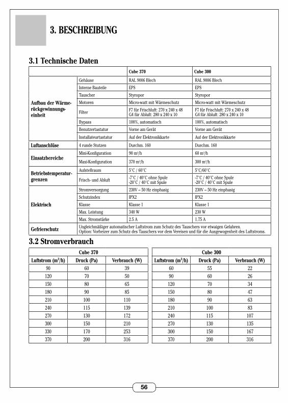
3.1 Technische DatenCube 370 Cube 300
Aufbau der Wärme-rückgewinnungs-einheit
Gehäuse RAL9006Blech RAL9006Blech
Interne Bauteile EPS EPS
Tauscher Styropor Styropor
Motoren Micro-wattmitWärmeschutz Micro-wattmitWärmeschutz
Filter F7fürFrischluft:270x240x48 G4fürAbluft:280x240x10
F7fürFrischluft:270x240x48 G4fürAbluft:280x240x10
Bypass 100%, automatisch 100%, automatisch
Benutzertastatur Vorne am Gerät Vorne am Gerät
Installateurtastatur Auf der Elektronikkarte Auf der Elektronikkarte
Luftanschlüse 4rundeStutzen Durchm . 160 Durchm . 160
EinsatzbereicheMini-Konfiguration 90m3/h 60 m3/h
Maxi-Konfiguration 370 m3/h 300 m3/h
Betriebstemperatur-grenzen
Aufstellraum 5°C / 60°C 5°C/60°C
Frisch- und Abluft -7°C / 40°C ohne Spule -20°C / 40°C mit Spule
-7°C / 40°C ohne Spule -20°C / 40°C mit Spule
Elektrisch
Stromversorgung 230V–50Hzeinphasig 230V–50Hzeinphasig
Schutzindex IPX2 IPX2
Klasse Klasse 1 Klasse 1
Max . Leistung 340 W 230 W
Max . Stromstärke 2 .5 A 1 .75 A
Gefrierschutz UngleichmäßigerautomatischerLuftstromzumSchutzdesTauschersvoretwaigenGefahren. Option:VorheizerzumSchutzdesTauschersvordemVereisenundfürdieAusgewogenheitdesLuftstroms.
3.2 Stromverbrauch
3. BESCHREIBUNG
Cube 370
Luftstrom (m3/h) Druck (Pa) Verbrauch (W)90 60 39
120 70 50150 80 65180 90 85210 100 110240 115 139270 130 172300 150 210330 170 253370 200 316
Cube 300
Luftstrom (m3/h) Druck (Pa) Verbrauch (W)60 55 2290 60 26
120 70 34150 80 47180 90 63210 100 83240 115 107270 130 135300 150 167370 200 316

57
3.3 Abmessungen
1094
1043
597
119
580
700
345
Ø 160
260
144
550
Ø DN 32, Siphon mit mindestens 50 mm .
NötigerFreiraumfürdenZugriff auf die Filter .
Gewicht: 43 kg (Cube 370) / 42 kg (Cube 300) .
58
4. INSTALLATION
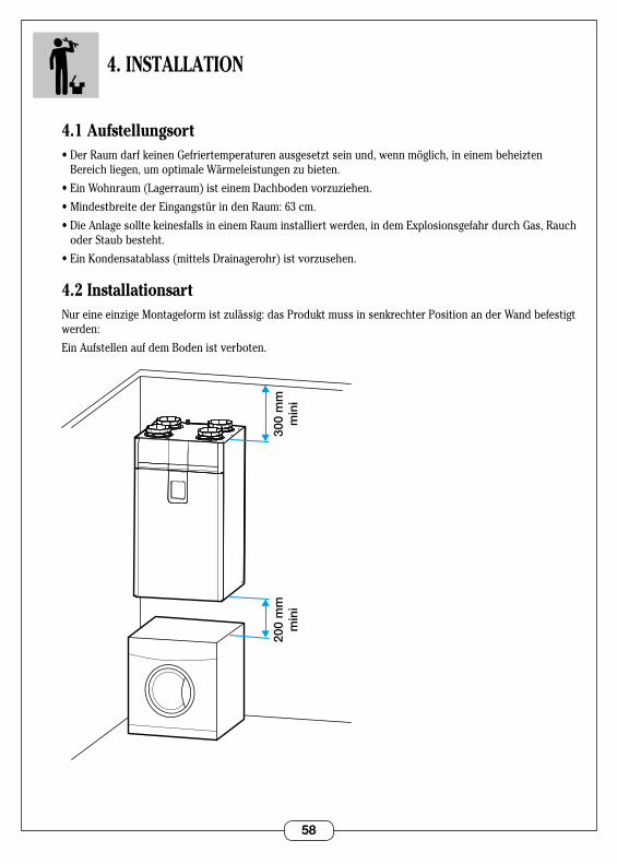
4.1 Aufstellungsort•DerRaumdarfkeinenGefriertemperaturenausgesetztseinund,wennmöglich,ineinembeheizten
Bereichliegen,umoptimaleWärmeleistungenzubieten.
•EinWohnraum(Lagerraum)isteinemDachbodenvorzuziehen.
•MindestbreitederEingangstürindenRaum:63cm.
•DieAnlagesolltekeinesfallsineinemRauminstalliertwerden,indemExplosionsgefahrdurchGas,Rauchoder Staub besteht .
•EinKondensatablass(mittelsDrainagerohr)istvorzusehen.
4.2 InstallationsartNureineeinzigeMontageformistzulässig:dasProduktmussinsenkrechterPositionanderWandbefestigt werden:
Ein Aufstellen auf dem Boden ist verboten .
200
mm
min
i30
0 m
mm
ini
59
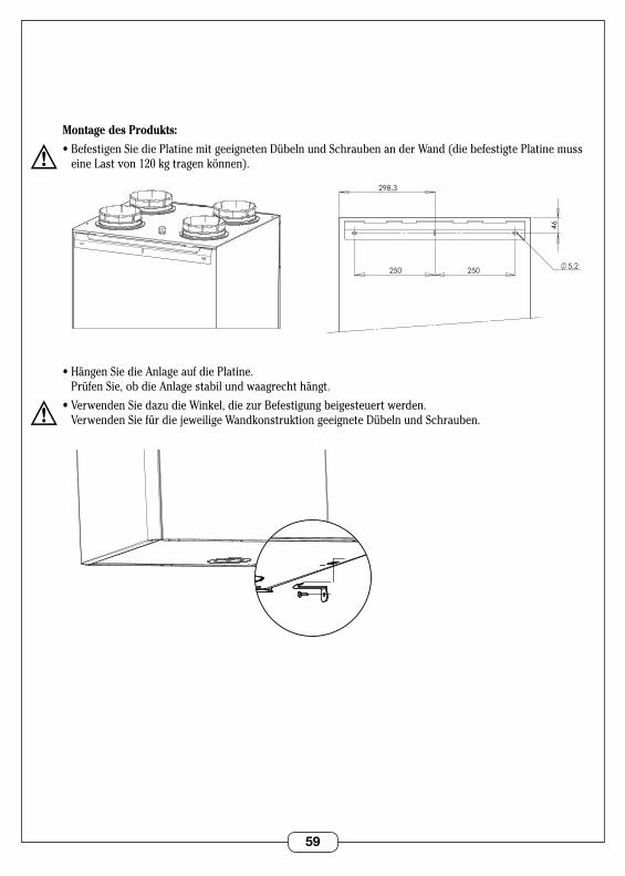
Montage des Produkts:
•BefestigenSiediePlatinemitgeeignetenDübelnundSchraubenanderWand(diebefestigtePlatinemuss eineLastvon120kgtragenkönnen).
•HängenSiedieAnlageaufdiePlatine. Prüfen Sie, ob die Anlage stabil und waagrecht hängt .
•VerwendenSiedazudieWinkel,diezurBefestigungbeigesteuertwerden. Verwenden Sie für die jeweilige Wandkonstruktion geeignete Dübeln und Schrauben .
5,2
46
250 250
298,3
VUE ARRIERE SUPPORT MURAL
5,2
46
250 250
298,3
VUE ARRIERE SUPPORT MURAL
VUE 3/4 DESSOUS EQUERRE MURALE
VUE 3/4 DESSOUS EQUERRE MURALE
60
4.3 Luftanschlüsse
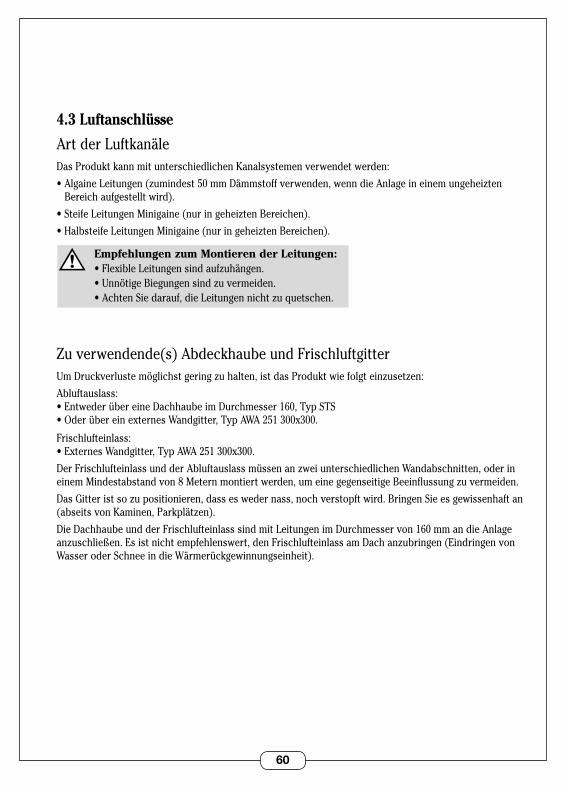
Art der LuftkanäleDas Produkt kann mit unterschiedlichen Kanalsystemen verwendet werden:
•AlgaineLeitungen(zumindest50mmDämmstoffverwenden,wenndieAnlageineinemungeheizten Bereich aufgestellt wird) .
•SteifeLeitungenMinigaine(nuringeheiztenBereichen).
•HalbsteifeLeitungenMinigaine(nuringeheiztenBereichen).
Empfehlungen zum Montieren der Leitungen: •FlexibleLeitungensindaufzuhängen. •UnnötigeBiegungensindzuvermeiden. •AchtenSiedarauf,dieLeitungennichtzuquetschen.
Zu verwendende(s) Abdeckhaube und Frischluftgitter UmDruckverlustemöglichstgeringzuhalten,istdasProduktwiefolgteinzusetzen:
Abluftauslass:•EntwederübereineDachhaubeimDurchmesser160,TypSTS•OderübereinexternesWandgitter,TypAWA251300x300.
Frischlufteinlass:•ExternesWandgitter,TypAWA251300x300.
DerFrischlufteinlassundderAbluftauslassmüssenanzweiunterschiedlichenWandabschnitten,oderineinemMindestabstandvon8Meternmontiertwerden,umeinegegenseitigeBeeinflussungzuvermeiden.
DasGitteristsozupositionieren,dasseswedernass,nochverstopftwird.BringenSieesgewissenhaftan(abseitsvonKaminen,Parkplätzen).
Die Dachhaube und der Frischlufteinlass sind mit Leitungen im Durchmesser von 160 mm an die Anlage anzuschließen.Esistnichtempfehlenswert,denFrischlufteinlassamDachanzubringen(EindringenvonWasser oder Schnee in die Wärmerückgewinnungseinheit) .
61
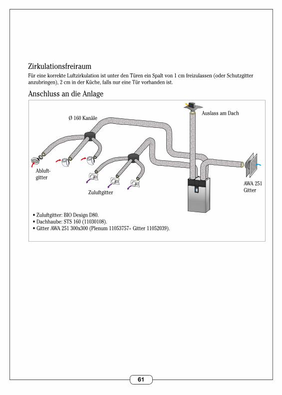
ZirkulationsfreiraumFüreinekorrekteLuftzirkulationistunterdenTüreneinSpaltvon1cmfreizulassen(oderSchutzgitteranzubringen),2cminderKüche,fallsnureineTürvorhandenist.
Anschluss an die Anlage
Zuluftgitter
•Zuluftgitter:BIODesignD80.•Dachhaube:STS160(11030108).•GitterAWA251300x300(Plenum11053757+Gitter11052039).
Abluft- gitter
Ø 160 KanäleAuslass am Dach
AWA 251 Gitter
62
4.4 - Stromanschluss
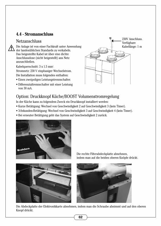
NetzanschlussDie Anlage ist von einer Fachkraft unter Anwendung derlandesüblichenStandardszuverkabeln. Das beigestellte Kabel ist über eine dichte Anschlussdose(nichtbeigestellt)ansNetz anzuschließen.
Kabelquerschnitt: 3 x 1 .5 mm2 .
Stromnetz:230VeinphasigerWechselstrom.Die Installation muss folgendes enthalten:•EinenzweipoligenLeistungstrennschalter.
•DifferenzialtrennschaltermiteinerLeistung von 30 mA .
Option: Druckknopf Küche/BOOST VolumenstromregelungInderKüchekannzufolgendemZweckeinDruckknopfinstalliertwerden:•KurzeBetätigung:WechselvonGeschwindigkeit2aufGeschwindigkeit3(keinTimer).•3-Sekunden-Betätigung:WechselvonGeschwindigkeit3aufGeschwindigkeit4(keinTimer).•BeierneuterBetätigunggehtdasSystemaufGeschwindigkeit2zurück.
Die rechte Filterabdeckplatte abnehmen, indemmanaufdiebeidenoberenKnöpfedrückt.
Die Abdeckplatte der Elektronikkarte abnehmen, indem man die Schraube abnimmt und auf den oberen Knopf drückt .
VUE 3/4 DESSUS SORTIE CORDON
230V Anschluss . Verfügbare Kabellänge: 1 m
63
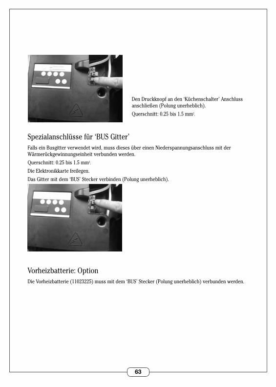
Den Druckknopf an den ‘Küchenschalter’ Anschluss anschließen(Polungunerheblich).
Querschnitt: 0 .25 bis 1 .5 mm2 .
Spezialanschlüssefür‘BUSGitter’Falls ein Busgitter verwendet wird, muss dieses über einen Niederspannungsanschluss mit der Wärmerückgewinnungseinheit verbunden werden .
Querschnitt: 0 .25 bis 1 .5 mm2 .
Die Elektronikkarte freilegen .
Das Gitter mit dem ‘BUS’ Stecker verbinden (Polung unerheblich) .
Vorheizbatterie:OptionDieVorheizbatterie(11023225)mussmitdem‘BUS’Stecker(Polungunerheblich)verbundenwerden.

64
4.5 KondensatableitungVor Inbetriebnahme muss das Produkt über einen Siphon mit einem PVC Ablassrohr im Durchmesser 32 verbunden werden:
•VerwendenSieeinenSiphonmitzumindesteinem50mmBehälter,odereinenFlachsiphon.
•TauchenSiedenSiphoninsWasser,bevorSieihnandasProduktanschließen(außerdenFlachsiphon).
•AchtenSiedarauf,dasskeineLuftleckagezwischendemSiphonundderMaschinevorhandenist.
•VersionmitwasserstandslosemFlachsiphon.•VersionmitSiphon.

65
5. ERSTINBETRIEBNAHME
5.1 Wichtige Kontrollen vor der InbetriebnahmeÜberprüfen Sie die folgenden Punkte, bevor Sie den Strom einschalten:
•VergewissernSiesich,dassdasStromkabelnichtbeschädigtist.
•ÜberprüfenSiedieVersorgungsspannungunddiekorrektePositiondesNullleiters.
•DieAnlagemussgeerdetsein.
•PrüfenSie,obdieSteckerkabeldierichtigeFarbeaufweisen.
•VergewissernSiesich,dassdieLuftleitungenkorrektangeschlossensind.
•VergewissernSiesich,dassderKondensatablasskorrektundübereinenSiphonmitderAblassleitungverbunden ist .
5.2 Zugriff auf die Konfigurationstastatur
Die rechte Filterabdeckplatte abnehmen, indemmanaufdiebeidenoberenKnöpfedrückt.
Die Abdeckplatte der Elektronikkarte abnehmen, indem man die Schraube abnimmt und auf den oberen Knopf drückt .
66
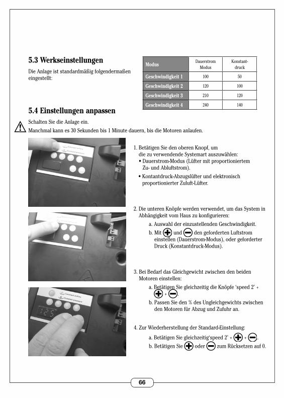
5.3 WerkseinstellungenDieAnlageiststandardmäßigfolgendermaßen eingestellt:
5.4 Einstellungen anpassenSchalten Sie die Anlage ein .
Manchmal kann es 30 Sekunden bis 1 Minute dauern, bis die Motoren anlaufen .
1 . Betätigen Sie den oberen Knopf, um diezuverwendendeSystemartauszuwählen: •Dauerstrom-Modus(Lüftermitproportioniertem
Zu- und Abluftstrom) .
•Kontantdruck-Abzugslüfterundelektronisch proportionierter Zuluft-Lüfter .
2.DieunterenKnöpfewerdenverwendet,umdasSysteminAbhängigkeitvomHauszukonfigurieren:
a.AuswahldereinzustellendenGeschwindigkeit.
b . Mit und den geforderten Luftstrom einstellen (Dauerstrom-Modus), oder geforderter Druck (Konstantdruck-Modus) .
3.BeiBedarfdasGleichgewichtzwischendenbeidenMotoren einstellen:
a.BetätigenSiegleichzeitigdieKnöpfe‘speed2’++ .
b.PassenSieden%desUngleichgewichtszwischendenMotorenfürAbzugundZufuhran.
4 . Zur Wiederherstellung der Standard-Einstellung:
a.BetätigenSiegleichzeitig‘speed 2’+ + .
b . Betätigen Sie oder zumRücksetzenauf0.
ModusDauerstrom
ModusKonstant-
druck
Geschwindigkeit 1 100 50
Geschwindigkeit 2 120 100
Geschwindigkeit 3 210 120
Geschwindigkeit 4 240 140
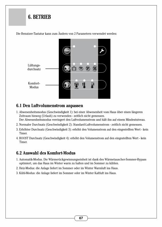
67
6. BETRIEB
DieBenutzer-TastaturkannzumÄndernvon2Parameternverwendetwerden:
6.1 Den Luftvolumenstrom anpassen1 . Abwesenheitsmodus (Geschwindigkeit 1): bei einer Abwesenheit vom Haus über einen längeren
Zeitraumhinweg(Urlaub)zuverwenden-zeitlichnichtgemessen. Der Abwesenheitsmodus verringert den Luftvolumenstrom und hält ihn auf einem Mindestniveau .
2.NormalerDurchsatz(Geschwindigkeit2):Standard-Luftvolumenstrom-zeitlichnichtgemessen.
3.ErhöhterDurchsatz(Geschwindigkeit3):erhöhtdenVolumenstromaufdeneingestelltenWert-keinTimer .
4.BOOSTDurchsatz(Geschwindigkeit4):erhöhtdenVolumenstromaufdeneingestelltenWert-kein Timer .
6.2 Auswahl des Komfort-Modus1 . Automatik-Modus . Die Wärmerückgewinnungseinheit ist dank des Wärmetauscher-Sommer-Bypass
optimiert,umdasHausimWinterwarmzuhaltenundimSommerzukühlen.
2.Heiz-Modus:dieAnlageliefertimSommeroderimWinterWarmluftinsHaus.
3 . Kühl-Modus: die Anlage liefert im Sommer oder im Winter Kaltluft ins Haus .
0
SDBType Logement
CellierWC
1 2 3 4 5/6/7
Hygro
Auto
0
SDBType Logement
CellierWC
1 2 3 4 5/6/7
Hygro
Auto
Lüftungs- durchsatz
Komfort- Modus
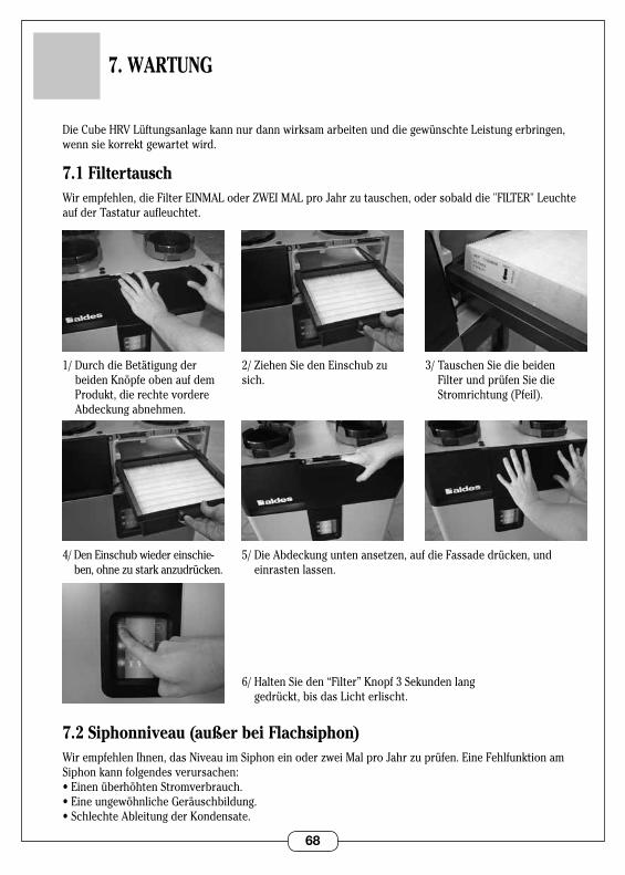
68
7. WARTUNG
Die Cube HRV Lüftungsanlage kann nur dann wirksam arbeiten und die gewünschte Leistung erbringen, wenn sie korrekt gewartet wird .
7.1 FiltertauschWirempfehlen,dieFilterEINMALoderZWEIMALproJahrzutauschen,odersobalddie"FILTER"Leuchteauf der Tastatur aufleuchtet .
7.2 Siphonniveau (außer bei Flachsiphon)WirempfehlenIhnen,dasNiveauimSiphoneinoderzweiMalproJahrzuprüfen.EineFehlfunktionamSiphon kann folgendes verursachen:•EinenüberhöhtenStromverbrauch.•EineungewöhnlicheGeräuschbildung.•SchlechteAbleitungderKondensate.
2/ZiehenSiedenEinschubzusich .
5/DieAbdeckunguntenansetzen,aufdieFassadedrücken,und einrasten lassen .
3/ Tauschen Sie die beiden Filter und prüfen Sie die Stromrichtung (Pfeil) .
1/ Durch die Betätigung der beidenKnöpfeobenaufdemProdukt, die rechte vordere Abdeckung abnehmen .
4/ Den Einschub wieder einschie-ben,ohnezustarkanzudrücken.
6/ Halten Sie den “Filter” Knopf 3 Sekunden lang gedrückt, bis das Licht erlischt .
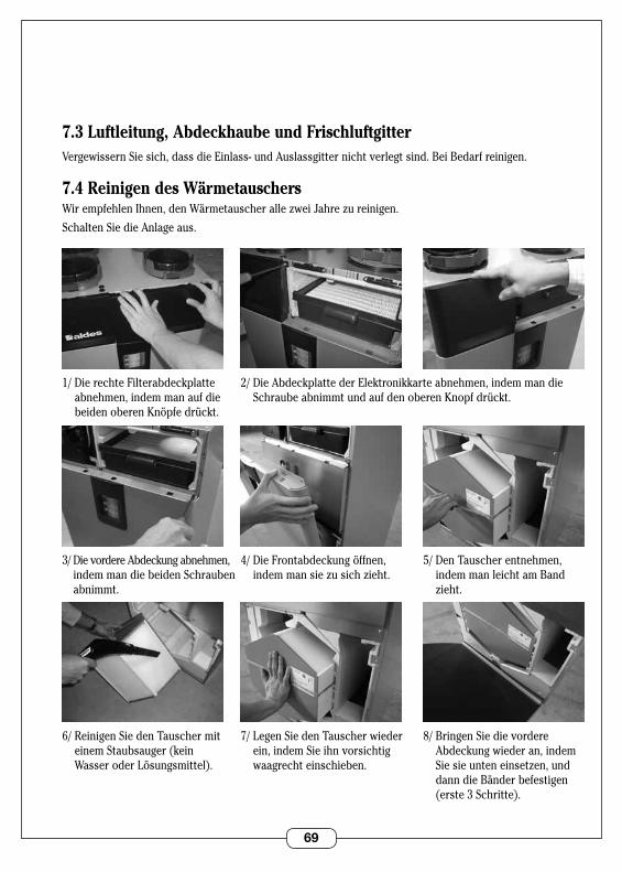
69
7.3 Luftleitung, Abdeckhaube und FrischluftgitterVergewissern Sie sich, dass die Einlass- und Auslassgitter nicht verlegt sind . Bei Bedarf reinigen .
7.4 Reinigen des WärmetauschersWirempfehlenIhnen,denWärmetauscherallezweiJahrezureinigen.
Schalten Sie die Anlage aus .
2/ Die Abdeckplatte der Elektronikkarte abnehmen, indem man die Schraube abnimmt und auf den oberen Knopf drückt .
4/DieFrontabdeckungöffnen,indemmansiezusichzieht.
5/ Den Tauscher entnehmen, indem man leicht am Band zieht.
1/ Die rechte Filterabdeckplatte abnehmen, indem man auf die beidenoberenKnöpfedrückt.
3/ Die vordere Abdeckung abnehmen, indem man die beiden Schrauben abnimmt .
7/ Legen Sie den Tauscher wieder ein, indem Sie ihn vorsichtig waagrecht einschieben .
8/BringenSiedievordereAbdeckung wieder an, indem Siesieunteneinsetzen,unddann die Bänder befestigen (erste 3 Schritte) .
6/ Reinigen Sie den Tauscher mit einem Staubsauger (kein WasseroderLösungsmittel).

70
Cube 370 Cube 300
Reparatur Beschreibung Code
1Ersatz- filterpack (2G4 + 1 F7)
11023221 11023221
2Motor + Spule (1)
11129574 11023222
3Elektronik- karte (1)
11129588 11129588
8. FEHLERSUCHE
Bei Auftreten einer Fehlermeldung (in rot) wenden Sie sich bitte an Ihren Installateur oder Ihren Instandhaltungsbetrieb .
Fehler Ursache Lösung
Die "Filter" Leuchte leuchtet
-DieFiltersindzutauschen.- Tauschen Sie die Filter . Siehe 7 .1 . - Danach drücken Sie auf “Filter” .
Die Störungsleuchte leuchtet
- Problem mit den Motoren .- Problem mit den Temperaturfühlern .
- 30 Sek . lang ausschalten und wieder einschalten . - Wenden Sie sich an Ihren Installateur, wenn das Gerät nicht anläuft .
Die Zuluft ist zu heiß -Komfort-ModusimHeiz-Modus.- Drehen Sie den Wahlschalter für Komfort-Modus
auf "Kühl"-Modus . Siehe 6 .2 .
Die Zuluft ist zu kalt - Komfort-Modus im Kühl-Modus .- Drehen Sie den Wahlschalter für Komfort-Modus
auf"Heiz"-Modus.Siehe6.2.
Tropfgeräusch - Der Siphon funktioniert nicht .- Das Wasserablassrohr ist verstopft .
- Prüfen Sie, ob Wasser im Siphon ist . - Machen Sie das Rohr frei .
Geringe Luftströmung an den Gittern
- Die Leitungen sind nicht richtig ausgewogen .- Lecks in den Kanälen .
-ÜberprüfenSiedieLängenderKanalabzweigungen.- Vergewissern Sie sich, dass die Kanäle korrekt befestigt sind .
Das System arbeitet laut
- Die Luftleitungen sind gequetscht oder weisen zuvieleBiegungenauf.- Das System ist für das Haus nicht richtig konfi-guriert .- Die Filter sind verstopft .
- Überprüfen Sie die Kanäle .- Überprüfen Sie die Konfiguration der Einheit . Siehe 5 .3 .3 .- Tauschen Sie die Filter . Siehe 7 .1 .
Die Einheit läuft nicht an
-DasHygroGitterwurdefalschreferenziert.- Falscher Kontakt mit dem BUS Link .-Wartezeitzukurz.
- Verwenden Sie das BUS Hygro Gitter . Siehe 5 .- Überprüfen Sie das Verbindungskabel . Siehe 5 .- Warten Sie vor dem Einschalten etwa 30 Sek . bis
1Minutezu.
9. ERSATZTEILE
3
2
1
2

71
10. GARANTIE
10.1 Allgemeine GarantiebestimmungenLesen Sie bitte die allgemeinen Verkaufsbedingungen auf unserer Website www .aldes .fr durch .
DieAnlageistvoneinerqualifiziertenFachkraftentsprechendallengeltendenVorschriften,StandardsundEmpfehlungenzuinstallieren,dieindenAnleitungenangeführtsind.DieAnlageistnormalundregelkonformzuverwendenundvoneinerFachkraftzuwarten.
10.2 GarantielaufzeitAuf das Produkt wird eine Garantie von 2 Jahren gewährt . Die Garantie umfasst lediglich den Austausch von Teilen,nichtjedochdieArbeitszeit.
DieGarantiezeittrittamTagdesKaufsimGeschäftinKraft,wobeidieRechnungalsBelegfürdiesesDatumherangezogenwird.
10.3 AusnahmebestimmungenSämtliche Defekte, die auf eine Nicht-Beachtung der Herstellerempfehlungen, aktueller Vorschriften und fehlendeInstandhaltungzurückzuführensind,sindvondenGarantiebestimmungenausgenommen.
10.4 Kundendienst Bei Auftreten eines Problems wenden Sie sich bitte an Ihren Installateur oder Händler .
Dieses Produkt darf keinesfalls mit dem Hausmüll entsorgt werden . Bei Lebensende des GerätesoderimFalleeinesAustauschsistesineinemAltstoffsammelzentrumzuentsorgenoderzueinemHändlerzurückzuschicken.
ALDES ist Mitglied des Öko-Verbandes Eco Systemes www .ecosystemes .fr .

72 RC
S 95
6 50
6 82
8 - G
edru
ckt i
n Fr
ankr
eich
- 11
0295
79-B
- AL
DES
beh
ält s
ich
das
Rec
ht v
or, a
lle h
ier e
ntha
ltene
n te
chni
sche
n In
form
atio
nen
zu ä
nder
n. D
er In
halt
dies
er A
nlei
tung
kan
n oh
ne V
oran
künd
igun
g ge
ände
rt w
erde
n.
www.aldes.com
73
Montagehandleiding
www.aldes.com
Cube 300 en 370 micro-watt ventilatiesysteem met warmteterugwinning
RC
S 95
6 50
6 82
8 - G
edru
ckt i
n Fr
ankr
eich
- 11
0295
79-B
- AL
DES
beh
ält s
ich
das
Rec
ht v
or, a
lle h
ier e
ntha
ltene
n te
chni
sche
n In
form
atio
nen
zu ä
nder
n. D
er In
halt
dies
er A
nlei
tung
kan
n oh
ne V
oran
künd
igun
g ge
ände
rt w
erde
n.
74
1. ALGEMENE INFORMATIE . . . . . . . . . . . . . . . . . . . . . . . . . . . . . . . . . . . . . . . . p.76 1 .1 Pictogrammen . . . . . . . . . . . . . . . . . . . . . . . . . . . . . . . . . . . . . . . . . . . . . . . . . 76 1 .2 Algemene informatie . . . . . . . . . . . . . . . . . . . . . . . . . . . . . . . . . . . . . . . . . . . 76 1 .3 Belangrijke voorschriften en opmerkingen . . . . . . . . . . . . . . . . . . . . . . . . 76 1 .4 Veiligheidsinstructies . . . . . . . . . . . . . . . . . . . . . . . . . . . . . . . . . . . . . . . . . . 76 1 .4 .1 Mechanische gevaren . . . . . . . . . . . . . . . . . . . . . . . . . . . . . . . . . . . 76 1 .4 .2 Inbedrijfstelling . . . . . . . . . . . . . . . . . . . . . . . . . . . . . . . . . . . . . . . . . 76 1 .4 .3 Gebruik . . . . . . . . . . . . . . . . . . . . . . . . . . . . . . . . . . . . . . . . . . . . . . . . 77 1 .4 .4 Onderhoud . . . . . . . . . . . . . . . . . . . . . . . . . . . . . . . . . . . . . . . . . . . . . 77 1 .4 .5 Ombouw . . . . . . . . . . . . . . . . . . . . . . . . . . . . . . . . . . . . . . . . . . . . . . . 77 1 .4 .6 Afdanking . . . . . . . . . . . . . . . . . . . . . . . . . . . . . . . . . . . . . . . . . . . . . . 77 1 .5 Verplaatsing en opslag . . . . . . . . . . . . . . . . . . . . . . . . . . . . . . . . . . . . . . . . . 78 1.6Verplaatsingmetbehulpvaneenheftruck(metenzondervorken) . . . 78 1 .7 Handmatige verplaatsing . . . . . . . . . . . . . . . . . . . . . . . . . . . . . . . . . . . . . . . . 78
2. WERKINGSPRINCIPE . . . . . . . . . . . . . . . . . . . . . . . . . . . . . . . . . . . . . . . . . . . . . 79 2 .1 Ventilatiesysteem met warmteterugwinning . . . . . . . . . . . . . . . . . . . . . . . 79 2 .2 Plaatsing . . . . . . . . . . . . . . . . . . . . . . . . . . . . . . . . . . . . . . . . . . . . . . . . . . . . . 79
3. BESCHRIJVING . . . . . . . . . . . . . . . . . . . . . . . . . . . . . . . . . . . . . . . . . . . . . . . . . . 80 3 .1 Technische gegevens . . . . . . . . . . . . . . . . . . . . . . . . . . . . . . . . . . . . . . . . . . 80 3 .2 Stroomverbruik . . . . . . . . . . . . . . . . . . . . . . . . . . . . . . . . . . . . . . . . . . . . . . . 80 3 .3 Afmetingen . . . . . . . . . . . . . . . . . . . . . . . . . . . . . . . . . . . . . . . . . . . . . . . . . . . 81
4. INSTALLATIE . . . . . . . . . . . . . . . . . . . . . . . . . . . . . . . . . . . . . . . . . . . . . . . . . . . . 82 4 .1 Installatielocatie . . . . . . . . . . . . . . . . . . . . . . . . . . . . . . . . . . . . . . . . . . . . . . . 82 4.2Installatiewijze . . . . . . . . . . . . . . . . . . . . . . . . . . . . . . . . . . . . . . . . . . . . . . . . 82 4 .3 Luchtkanaalaansluiting . . . . . . . . . . . . . . . . . . . . . . . . . . . . . . . . . . . . . . . . . 84 Luchtkanaalsysteem . . . . . . . . . . . . . . . . . . . . . . . . . . . . . . . . . . . . . . . . . 84 Te gebruiken type dakdoorvoer en verseluchtrooster . . . . . . . . . . . . . 84 Luchtspleet voor doorstroming . . . . . . . . . . . . . . . . . . . . . . . . . . . . . . . . 85 Aansluitingen op het apparaat . . . . . . . . . . . . . . . . . . . . . . . . . . . . . . . . . 85 4 .4 Elektrische aansluitingen . . . . . . . . . . . . . . . . . . . . . . . . . . . . . . . . . . . . . . . 86 Netaansluiting . . . . . . . . . . . . . . . . . . . . . . . . . . . . . . . . . . . . . . . . . . . . . . 86 Optie: drukknop keuken/BOOST luchtdebietregeling . . . . . . . . . . . . . 86 Specifieke aansluitingen voor vocht-gestuurde bediening . . . . . . . . . 87 4 .5 Afvoer van condenswater . . . . . . . . . . . . . . . . . . . . . . . . . . . . . . . . . . . . . . . 88
INHOUD
75
5. INBEDRIJFSTELLING . . . . . . . . . . . . . . . . . . . . . . . . . . . . . . . . . . . . . . . . . . . . . . 89 5 .1 Belangrijke controles voor inbedrijfstelling . . . . . . . . . . . . . . . . . . . . . . . . 89 5 .2 Toegang tot het configuratietoetsenbord . . . . . . . . . . . . . . . . . . . . . . . . . . 89 5 .3 Fabrieksinstellingen . . . . . . . . . . . . . . . . . . . . . . . . . . . . . . . . . . . . . . . . . . . . 90 5 .4 Instellingen aanpassen . . . . . . . . . . . . . . . . . . . . . . . . . . . . . . . . . . . . . . . . . . 90
6. GEBRUIK . . . . . . . . . . . . . . . . . . . . . . . . . . . . . . . . . . . . . . . . . . . . . . . . . . . . . . . 91 6 .1 Ventilatiedebiet instellen . . . . . . . . . . . . . . . . . . . . . . . . . . . . . . . . . . . . . . . 91 6.2Comfortstandkiezen . . . . . . . . . . . . . . . . . . . . . . . . . . . . . . . . . . . . . . . . . . . 91
7. ONDERHOUD . . . . . . . . . . . . . . . . . . . . . . . . . . . . . . . . . . . . . . . . . . . . . . . . . . . 92 7 .1 Filters vervangen . . . . . . . . . . . . . . . . . . . . . . . . . . . . . . . . . . . . . . . . . . . . . . 92 7 .2 Waterniveau in de sifon . . . . . . . . . . . . . . . . . . . . . . . . . . . . . . . . . . . . . . . . . 92 7 .3 Luchtkanalensysteem, dakafvoer en verseluchtrooster . . . . . . . . . . . . . . 93 7 .4 Warmtewisselaar reinigen . . . . . . . . . . . . . . . . . . . . . . . . . . . . . . . . . . . . . . . 93
8. PROBLEEMOPLOSSING . . . . . . . . . . . . . . . . . . . . . . . . . . . . . . . . . . . . . . . . . . . 94
9. ONDERDELEN . . . . . . . . . . . . . . . . . . . . . . . . . . . . . . . . . . . . . . . . . . . . . . . . . . . 94
10. GARANTIE . . . . . . . . . . . . . . . . . . . . . . . . . . . . . . . . . . . . . . . . . . . . . . . . . . . . . . 95 10 .1 Algemene garantievoorwaarden . . . . . . . . . . . . . . . . . . . . . . . . . . . . . . . . . 95 10 .2 Garantieperiode . . . . . . . . . . . . . . . . . . . . . . . . . . . . . . . . . . . . . . . . . . . . . . 95 10 .3 Uitsluitingen van garantie . . . . . . . . . . . . . . . . . . . . . . . . . . . . . . . . . . . . . . 95 10 .4 Technische servicedienst . . . . . . . . . . . . . . . . . . . . . . . . . . . . . . . . . . . . . . 95
76
1.1 Pictogrammen Gevaar of belangrijke informatie. Kans op letsel en schade aan apparatuur . Volg de instructies nauwkeurig op om de kans op letsel en schade aan apparatuur te voorkomen .
Paginaverwijzingen.Verwijzingennaaranderehandleidingenofanderepagina'svandehandleiding.
1.2 Algemene informatieWijstellenhetopprijsdatueenALDESproducthebtgekozen.Wijradenuaandezehandleidingtelezenendeinstructiesnauwgezettevolgenomervoortezorgendatuwapparaatcorrectwerkt.Alsfabrikantzijnwijnietaansprakelijkingevalvanoneigenlijkgebruik,slechtuitgevoerdonderhoudofgebrekaanonderhoudvanhetapparaat,nochingevalvanverkeerduitgevoerdeinstallatie.OmdekwaliteitvanonzeproductenvoortdurendtekunnenverbeterenbehoudtALDESzichhetrechtvooromdeinditdocumentvermeldespecificatiesopelkgewenstmomenttewijzigen.
Degoedewerkingvanhetapparaatisafhankelijkvanofdezeinstructieszorgvuldigwordenopgevolgd. Als deze voorschriften niet worden nagekomen, vervalt mogelijk de garantie.
1.3 Belangrijke voorschriften en opmerkingen Lees voor installatie, inbedrijfstelling en onderhoud van het ventilatiesysteem met warmteterugwinning
het 'Waarschuwingen en bepalingen'-blad dat bij het product is meegeleverd .
1.4 Veiligheidsinstructies
1 .4 .1 Mechanische gevaren •Hetmateriaalmoetwordenverplaatstengeïnstalleerdconformhetgewichtendeafmetingen
ervan .
•Hetapparaatdientopeendrogeplaatstewordengeïnstalleerdenmagnietwordenblootgesteldaan temperaturen onder nul (installaties binnenshuis) .
•Hetapparaatmoetwordengeplaatstvolgensdevoorschriftenvandefabrikant(hoofdstuk4.2).
1 .4 .2 Inbedrijfstelling •Probeernietomhetapparaatzelfteinstalleren.Ditproductmoetdoorvakbekwametechnici
wordengeïnstalleerdenonderhouden.
•Brenggeenwijzigingenaanindeelektrischevoeding.
•Hetapparaatisnietexplosieveiligenmagnietinexplosiegevaarlijkeomgevingen(ATEX)wordengeïnstalleerd.
•Alleverbindingenmoetenzijnaangeslotenvoordathetapparaatwordtopgestart(luchtkanalen,bedrading,condenswater).Hetapparaatmoetonmiddellijknadatdeaansluitingenzijnvoltooid,worden opgestart om condensvorming te voorkomen (hoofdstuk 5 .1).
•HetproductvoldoetaandeeisenvannormEN55014-2A1/A2(97/01/08editie)betreffendedebestendigheid tegen elektrostatische ontladingen .
1. ALGEMENE INFORMATIE
77
1 .4 .3 Gebruik •Beleenvakmanalseenstoringoptreedt.
•Steekgeenvreemdevoorwerpenindeluchtinlaaten-uitlaatroosters.
•Nietsmagdeluchtcirculatieblokkeren.
•Klimnietophetgeraamtevanhetapparaat.
•Uwruimtevoldoetaanbepaaldeveiligheidsnormen:umagnietsaanderuimtewijzigen(ventilatie,rookkanalen,openingen,etc.)zondereerstuwinstallateuromtoestemmingtevragen.
1 .4 .4 Onderhoud •Probeernietomhetapparaatzelfterepareren.
•Ditapparaatbevatgeenonderdelendiedoordegebruikerkunnenwordengerepareerd.Alsupanelen verwijdert, kunt u aan gevaarlijke spanningen bloot komen te staan .
•Destroomuitzettenisnietvoldoendeomhetgevaarvanelektrischeschokken(condensatoren)weg te nemen .
•Zetdestroomuitingevalvanabnormalegeluiden,geurenofdeaanwezigheidvanrookenneemcontact op met uw installateur .
•Zetdestroomuitvoordatuhetapparaatgaatreinigen. •Gebruikgeenagressievereinigings-ofoplosmiddelenomhetapparaattereinigen. •Gebruikgeenhogedrukreinigersomdeluchtroosterstereinigen.Uloopthetrisicodatude
luchtwarmtewisselaar beschadigt en dat er water in aanraking komt met elektrische circuits .
1 .4 .5 Ombouw •Hetisverbodenomwijzigingenaanhetapparaataantebrengen.Componentenmogenuitsluitend
door een deskundige vakman worden vervangen met behulp van originele onderdelen geleverd door de fabrikant .
1 .4 .6 Afdanking •Koppeldevoedingskabellosvoordatuhetapparaatuitelkaarneemt.
•Bijverbrandingvanbepaaldecomponentenkunnengiftigegassenvrijkomen;hetapparaatmagniet in een vuilverbranding worden verwerkt .
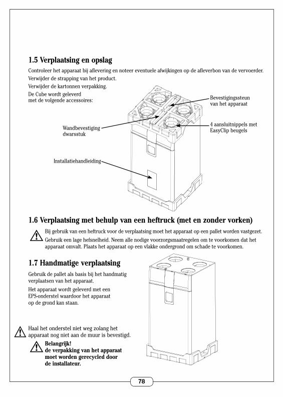
78
1.5 Verplaatsing en opslagControleer het apparaat bij aflevering en noteer eventuele afwijkingen op de afleverbon van de vervoerder .Verwijder de strapping van het product .Verwijder de kartonnen verpakking .De Cube wordt geleverd met de volgende accessoires:
1.6 Verplaatsing met behulp van een heftruck (met en zonder vorken) Bijgebruikvaneenheftruckvoordeverplaatsingmoethetapparaatopeenpalletwordenvastgezet.
Gebruikeenlagehefsnelheid.Neemallenodigevoorzorgsmaatregelenomtevoorkomendathetapparaat omvalt . Plaats het apparaat op een vlakke ondergrond om schade te voorkomen .
1.7 Handmatige verplaatsingGebruik de pallet als basis bij het handmatig verplaatsen van het apparaat .
Het apparaat wordt geleverd met een EPS-onderstel waardoor het apparaat op de grond kan staan .
Haalhetonderstelnietwegzolanghet apparaat nog niet aan de muur is bevestigd . Belangrijk! de verpakking van het apparaat moet worden gerecycled door de installateur.
VUE 3/4 AVANT BARQUETTE DESSUS
4 aansluitnippels met EasyClip beugels
Installatiehandleiding
Bevestigingssteun van het apparaat
Wandbevestiging dwarsstuk
VUE 3/4 AVANT BARQUETTE DESSOUS
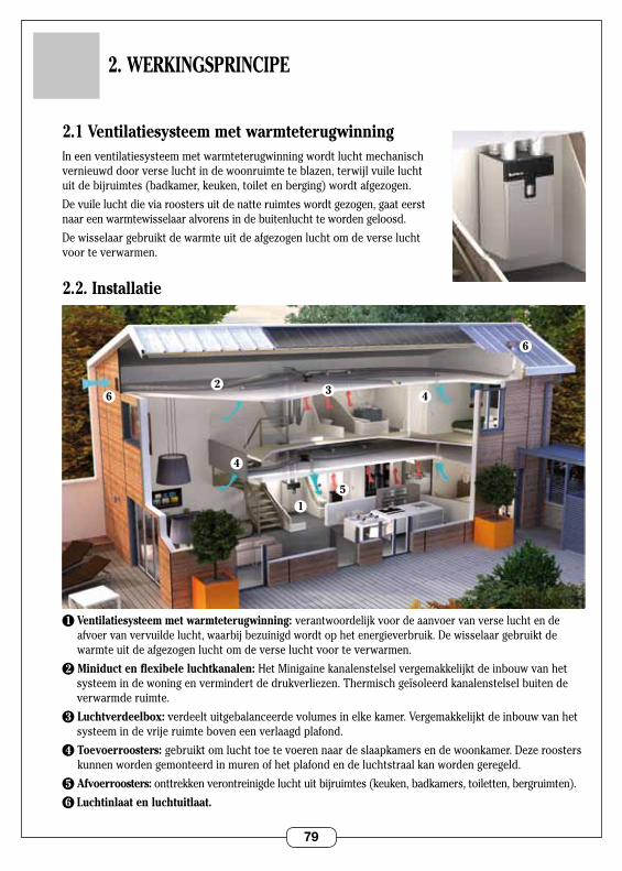
79
2.1 Ventilatiesysteem met warmteterugwinning In een ventilatiesysteem met warmteterugwinning wordt lucht mechanisch vernieuwddoorverseluchtindewoonruimteteblazen,terwijlvuileluchtuitdebijruimtes(badkamer,keuken,toiletenberging)wordtafgezogen.
Devuileluchtdieviaroostersuitdenatteruimteswordtgezogen,gaateerstnaar een warmtewisselaar alvorens in de buitenlucht te worden geloosd .
Dewisselaargebruiktdewarmteuitdeafgezogenluchtomdeverseluchtvoor te verwarmen .
2.2. Installatie
1 Ventilatiesysteem met warmteterugwinning: verantwoordelijk voor de aanvoer van verse lucht en de afvoervanvervuildelucht,waarbijbezuinigdwordtophetenergieverbruik. De wisselaar gebruikt de warmteuitdeafgezogenluchtomdeverseluchtvoorteverwarmen.
2 Miniduct en flexibele luchtkanalen: Het Minigaine kanalenstelsel vergemakkelijkt de inbouw van het systeemindewoningenvermindertdedrukverliezen.Thermischgeïsoleerdkanalenstelselbuitende verwarmde ruimte .
3 Luchtverdeelbox: verdeelt uitgebalanceerde volumes in elke kamer . Vergemakkelijkt de inbouw van het systeem in de vrije ruimte boven een verlaagd plafond .
4 Toevoerroosters: gebruiktomluchttoetevoerennaardeslaapkamersendewoonkamer.Dezeroosterskunnen worden gemonteerd in muren of het plafond en de luchtstraal kan worden geregeld .
5 Afvoerroosters: onttrekken verontreinigde lucht uit bijruimtes (keuken, badkamers, toiletten, bergruimten) .
6 Luchtinlaat en luchtuitlaat.
2. WERKINGSPRINCIPE
62
6
1
4
4
5
3
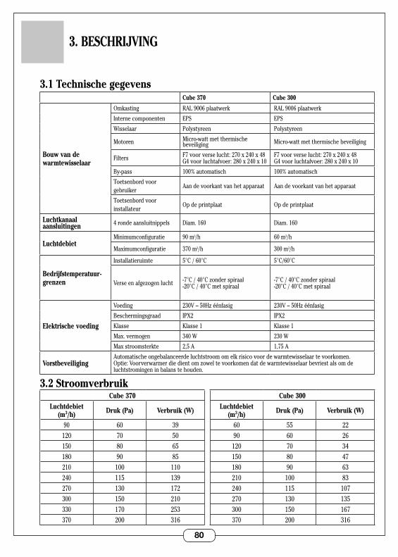
80
3.1 Technische gegevensCube 370 Cube 300
Bouw van de warmtewisselaar
Omkasting RAL9006plaatwerk RAL9006plaatwerk
Interne componenten EPS EPS
Wisselaar Polystyreen Polystyreen
Motoren Micro-watt met thermische beveiliging Micro-watt met thermische beveiliging
Filters F7voorverselucht:270x240x48 G4voorluchtafvoer:280x240x10
F7voorverselucht:270x240x48 G4voorluchtafvoer:280x240x10
By-pass 100% automatisch 100% automatisch
Toetsenbord voor gebruiker
Aan de voorkant van het apparaat Aan de voorkant van het apparaat
Toetsenbord voor installateur
Op de printplaat Op de printplaat
Luchtkanaal aansluitingen 4 ronde aansluitnippels Diam . 160 Diam . 160
LuchtdebietMinimumconfiguratie 90m3/h 60 m3/h
Maximumconfiguratie 370 m3/h 300 m3/h
Bedrijfstemperatuur-grenzen
Installatieruimte 5°C / 60°C 5°C/60°C
Verseenafgezogenlucht -7°C/40°Czonderspiraal -20°C / 40°C met spiraal
-7°C/40°Czonderspiraal -20°C / 40°C met spiraal
Elektrische voeding
Voeding 230V–50Hzéénfasig 230V–50Hzéénfasig
Beschermingsgraad IPX2 IPX2
Klasse Klasse 1 Klasse 1
Max . vermogen 340 W 230 W
Max stroomsterkte 2,5 A 1,75 A
VorstbeveiligingAutomatische ongebalanceerde luchtstroom om elk risico voor de warmtewisselaar te voorkomen . Optie:Voorverwarmerdiedientomzoweltevoorkomendatdewarmtewisselaarbevriestalsomdeluchtstromingen in balans te houden .
3.2 Stroomverbruik
3. BESCHRIJVING
Cube 370
Luchtdebiet (m3/h) Druk (Pa) Verbruik (W)
90 60 39120 70 50150 80 65180 90 85210 100 110240 115 139270 130 172300 150 210330 170 253370 200 316
Cube 300
Luchtdebiet (m3/h) Druk (Pa) Verbruik (W)
60 55 2290 60 26
120 70 34150 80 47180 90 63210 100 83240 115 107270 130 135300 150 167370 200 316
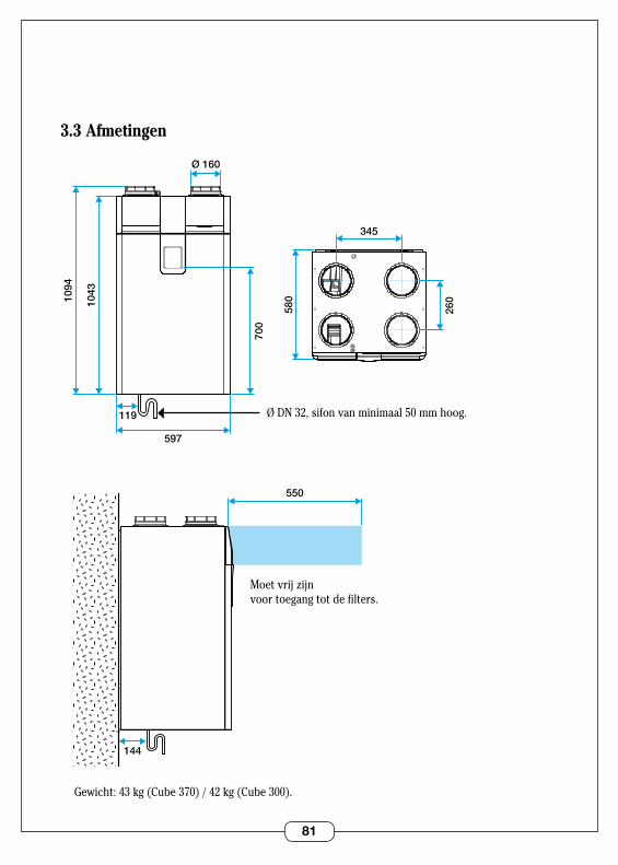
81
3.3 Afmetingen
1094
1043
597
119
580
700
345
Ø 160
260
144
550
Ø DN 32, sifon van minimaal 50 mm hoog .
Moetvrijzijnvoor toegang tot de filters .
Gewicht: 43 kg (Cube 370) / 42 kg (Cube 300) .
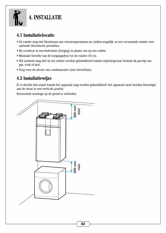
82
4. INSTALLATIE
4.1 Installatielocatie•Deruimtemagnietblootstaanaanvriestemperaturenen,indienmogelijk,ineenverwarmderuimtevoor
optimale thermische prestaties .
•Bijvoorkeurineenleefruimte(berging)inplaatsvanopeenzolder.
•Minimalebreedtevandetoegangsdeurtotderuimte:63cm.
•Hetsysteemmagnietineenruimtewordengeïnstalleerdwaarinexplosiegevaarbestaatalsgevolgvangas, rook of stof .
•Zorgvoordeafvoervancondenswater(metafvoerbuis).
4.2 InstallatiewijzeErisslechtséénstandwaarinhetapparaatmagwordengeïnstalleerd:hetapparaatmoetwordenbevestigdaan de muur in een verticale positie:
Horizontalemontageopdegrondisverboden.
200
mm
min
i30
0 m
mm
ini
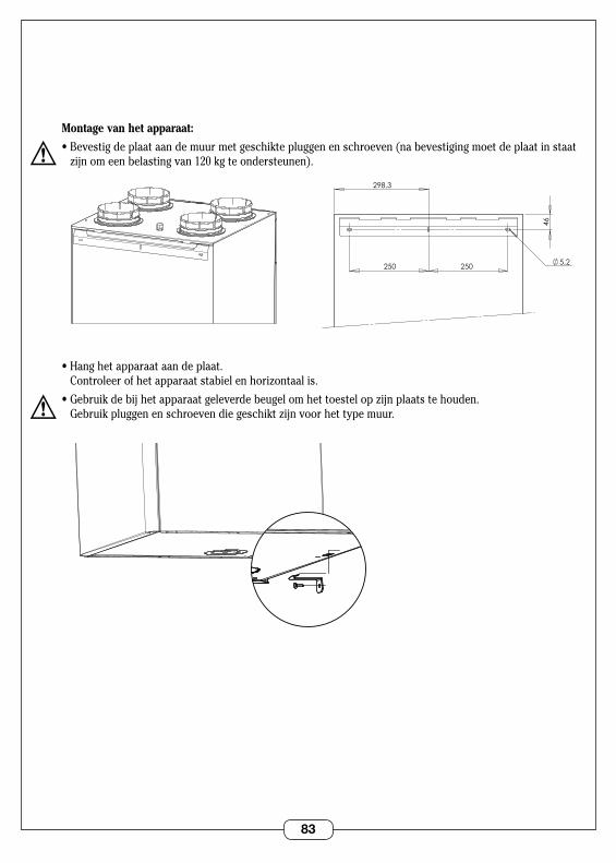
83
Montage van het apparaat:
•Bevestigdeplaataandemuurmetgeschiktepluggenenschroeven(nabevestigingmoetdeplaatinstaatzijnomeenbelastingvan120kgteondersteunen).
•Hanghetapparaataandeplaat. Controleerofhetapparaatstabielenhorizontaalis.
•Gebruikdebijhetapparaatgeleverdebeugelomhettoestelopzijnplaatstehouden. Gebruikpluggenenschroevendiegeschiktzijnvoorhettypemuur.
5,2
46
250 250
298,3
VUE ARRIERE SUPPORT MURAL
5,2
46
250 250
298,3
VUE ARRIERE SUPPORT MURAL
VUE 3/4 DESSOUS EQUERRE MURALE
VUE 3/4 DESSOUS EQUERRE MURALE
84
4.3 Luchtkanaal aansluitingen
Type luchtkanalensysteemHet apparaat kan worden gebruikt met verschillende soorten kanalen:
•Algaineflexibeleluchtkanalen(gebruikminstens50mmisolatiemateriaalindiengeïnstalleerdin onverwarmde ruimtes) .
•Minigainestijveluchtkanalen(enkelinverwarmderuimtes).
•Minigainehalfstijveluchtkanalen(enkelinverwarmderuimtes).
Aanbevelingen voor de montage van luchtkanalen: •Flexibeleluchtkanalenmoetenwordenopgehangen. •Voorkomonnodigebochten. •Zorgervoordatdeluchtkanalennietwordenplatgedrukt.
Te gebruiken type dakdoorvoer en verseluchtrooster Omdrukverliezentebeperkenmoethetapparaatalsvolgtwordengebruikt:
Afzuigingvanvervuildelucht:•Ofwelviaeendakafvoermeteendiametervan160typeSTS.•Ofwelviaeenbuitenmuurrooster,typeAWA251300x300.
Verse luchtinlaat:•Buitenmuurrooster,typeAWA251300x300.
Deroostersvoorverseluchtenvuileluchtmoetenop2verschillendemurenwordengeïnstalleerdoftenminste8meteruitelkaaromterugvoertevoorkomen.
Hetroostermoetzowordengeplaatstdathetnietnatkanwordenofverstoptkanraken.Bepaaldeplaatsweldoordacht(uitdebuurtvanschoorstenen,parkeerplaatsen,enz.).
De dakafvoer en de verse luchtinlaat moeten op het apparaat worden aangesloten met behulp van luchtkanalendie160mmindiameterzijn.Hetisnietaantebevelenomdeverseluchtinlaatophetdakteplaatsen(gevaarvooraanzuigenvanregenofsneeuwindewarmtewisselaar).
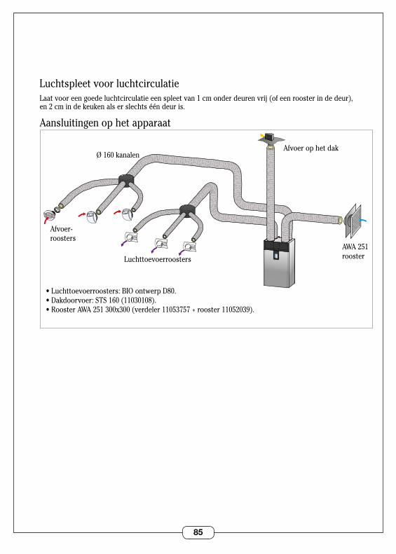
85
Luchtspleet voor luchtcirculatieLaat voor een goede luchtcirculatie een spleet van 1 cm onder deuren vrij (of een rooster in de deur), en 2 cm in de keuken als er slechts één deur is .
Aansluitingen op het apparaat
Luchttoevoerroosters
•Luchttoevoerroosters:BIOontwerpD80.•Dakdoorvoer:STS160(11030108).•RoosterAWA251300x300(verdeler11053757+rooster11052039).
Afvoer- roosters
Ø 160 kanalenAfvoer op het dak
AWA 251 rooster
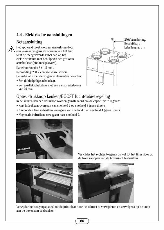
86
4.4 - Elektrische aansluitingen
NetaansluitingHet apparaat moet worden aangesloten door een vakman volgens de normen van het land . Sluit de meegeleverde kabel aan op het elektriciteitsnet met behulp van een gesloten aansluitkast (niet meegeleverd) .
Kabeldoorsnede: 3 x 1 .5 mm2 .
Netvoeding: 230 V eenfase wisselstroom .De installatie met de volgende elementen bevatten:•Eendubbelpoligeschakelaar.•Eenaardlekschakelaarmeteenaanspreekstroom
van 30 mA .
Optie: drukknop keuken/BOOST luchtdebietregelingIndekeukenkaneendrukknopwordengeïnstalleerdomdecapaciteitteregelen:•Kortindrukken:overgaanvansnelheid2opsnelheid3(geentimer).•3secondenlangindrukken:overgaanvansnelheid3opsnelheid4(geentimer).•Nogmaalsindrukken:teruggaannaarsnelheid2.
Verwijder het rechter toegangspaneel tot het filter door op de twee knoppen aan de bovenkant te drukken .
Verwijder het toegangspaneel tot de printplaat door de schroef te verwijderen en vervolgens op de knop aan de bovenkant te drukken .
VUE 3/4 DESSUS SORTIE CORDON
230V aansluiting . Beschikbare kabellengte: 1 m
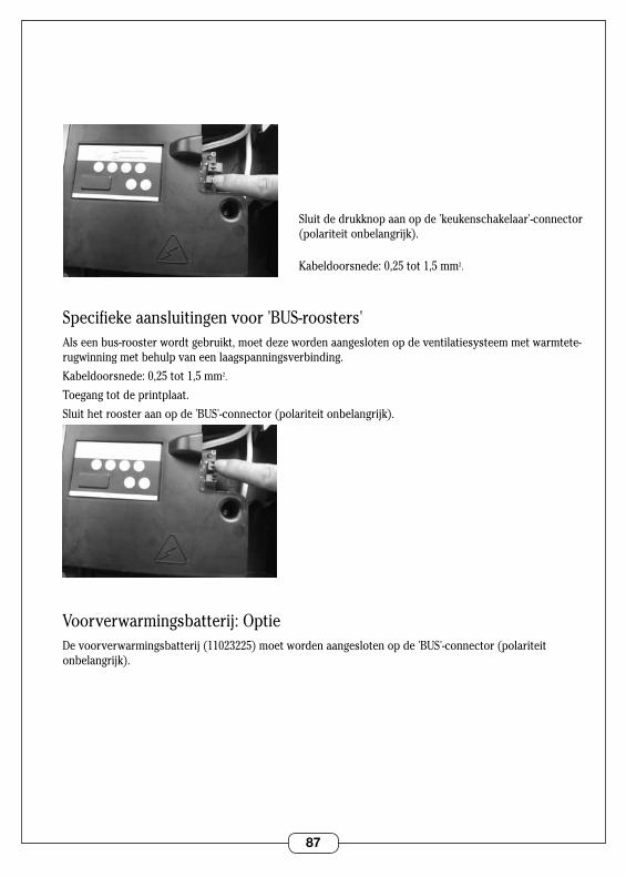
87
Sluit de drukknop aan op de 'keukenschakelaar'-connector (polariteit onbelangrijk) .
Kabeldoorsnede: 0,25 tot 1,5 mm2 .
Specifieke aansluitingen voor 'BUS-roosters'Alseenbus-roosterwordtgebruikt,moetdezewordenaangeslotenopdeventilatiesysteemmetwarmtete-rugwinning met behulp van een laagspanningsverbinding .
Kabeldoorsnede: 0,25 tot 1,5 mm2 .
Toegang tot de printplaat .
Sluit het rooster aan op de 'BUS'-connector (polariteit onbelangrijk) .
Voorverwarmingsbatterij: OptieDe voorverwarmingsbatterij (11023225) moet worden aangesloten op de 'BUS'-connector (polariteit onbelangrijk) .

88
4.5 Afvoer van condenswaterAlvorens het apparaat wordt opgestart, moet het worden aangesloten op een PVC-afvoerbuis diam . 32 via een sifon:
•Gebruikeenminstens50mmhogesifonwaarinwaterblijftstaanofeenhorizontale1-wegklep.
•Gietwaterindesifonvoordatudezeaansluit(nietvantoepassingopde1-wegklep).
•Zorgdatergeenluchtlekistussendesifonendemachine.
•Uitvoeringmeteen1-wegklepzonderwater. •Uitvoeringmeteensifon.

89
5. INBEDRIJFSTELLING
5.1 Belangrijke controles voor inbedrijfstellingControleer het volgende voordat u de stroom inschakelt:
•Controleerofdevoedingskabelnietbeschadigdis.
•Controleerdevoedingsspanningendejuistepositievandenulleider.
•Hetapparaatmoetgeaardzijn.
•Controleerofdedradenvandeaansluitingendejuistekleurhebben.
•Controleerofdeluchtkanalengoedzijnaangesloten.
•Controleerofdecondensafvoercorrectisaangeslotenopeenafvoerbuisviaeenstankafsluiting (bijv . sifon) .
5.2 Toegang tot het configuratietoetsenbord
Verwijder het rechter toegangspaneel tot het filter door op de twee knoppen aan de bovenkant te drukken .
Verwijder het toegangspaneel tot de printplaat door de schroef te verwijderen en vervolgens op de knop aan de bovenkant te drukken .
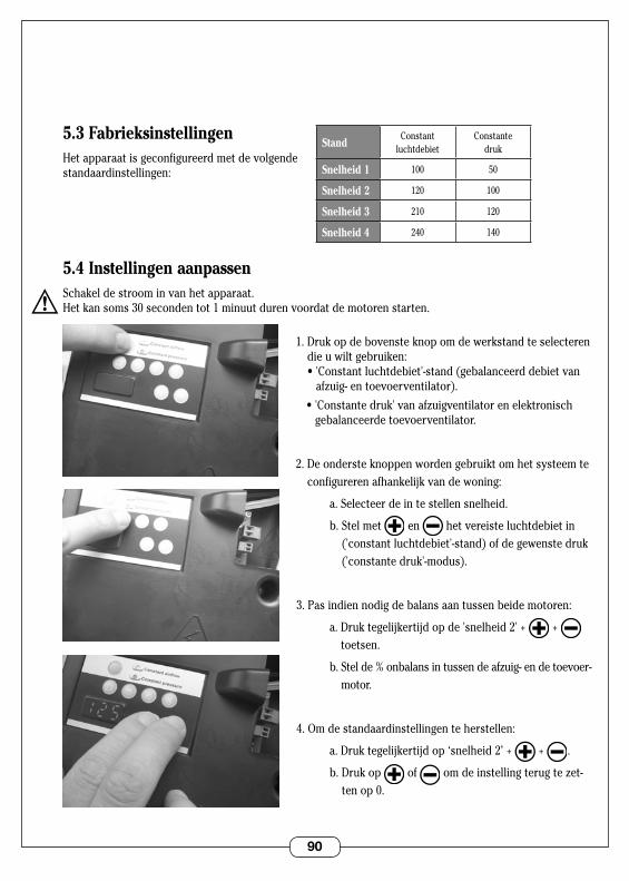
90
5.3 FabrieksinstellingenHet apparaat is geconfigureerd met de volgende standaardinstellingen:
5.4 Instellingen aanpassenSchakel de stroom in van het apparaat .Het kan soms 30 seconden tot 1 minuut duren voordat de motoren starten .
1 . Druk op de bovenste knop om de werkstand te selecteren die u wilt gebruiken: •'Constantluchtdebiet'-stand(gebalanceerddebietvan
afzuig-entoevoerventilator).
•'Constantedruk'vanafzuigventilatorenelektronischgebalanceerde toevoerventilator .
2 . De onderste knoppen worden gebruikt om het systeem te configureren afhankelijk van de woning:
a . Selecteer de in te stellen snelheid .
b . Stel met en het vereiste luchtdebiet in ('constant luchtdebiet'-stand) of de gewenste druk ('constante druk'-modus) .
3 . Pas indien nodig de balans aan tussen beide motoren:
a.Druktegelijkertijdopde'snelheid2'+ + toetsen .
b.Stelde%onbalansintussendeafzuig-endetoevoer-motor .
4 . Om de standaardinstellingen te herstellen:
a.Druktegelijkertijdop‘snelheid2’+ + .
b . Druk op of omdeinstellingterugtezet-ten op 0 .
StandConstant
luchtdebietConstante
druk
Snelheid 1 100 50
Snelheid 2 120 100
Snelheid 3 210 120
Snelheid 4 240 140
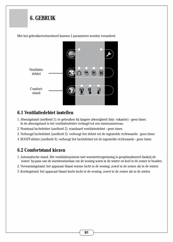
91
6. GEBRUIK
Met het gebruikertoetsenbord kunnen 2 parameters worden veranderd:
6.1 Ventilatiedebiet instellen1.Afwezigstand(snelheid1):tegebruikenbijlangereafwezigheid(bijv.vakantie)-geentimer.
Indeafwezigstandishetventilatiedebietverlaagdtoteenminimumniveau.
2 . Nominaal luchtdebiet (snelheid 2): standaard ventilatiedebiet - geen timer .
3 . Verhoogd luchtdebiet (snelheid 3): verhoogt het debiet tot de ingestelde richtwaarde - geen timer .
4 . BOOST-debiet (snelheid 4): verhoogt het luchtdebiet tot de ingestelde richtwaarde - geen timer .
6.2 Comfortstand kiezen1.Automatischestand.Hetventilatiesysteemmetwarmteterugwinningisgeoptimaliseerddankzijde
'zomer'by-passvandewarmtewisselaaromdewoningwarmindewinterenkoelindezomertehouden.
2.Verwarmingstand:hetapparaatblaastwarmeluchtindewoning,zowelindezomeralsindewinter.
3.Koelingstand:hetapparaatblaastkoeleluchtindewoning,zowelindezomeralsindewinter.
0
SDBType Logement
CellierWC
1 2 3 4 5/6/7
Hygro
Auto
0
SDBType Logement
CellierWC
1 2 3 4 5/6/7
Hygro
Auto
Ventilatie- debiet
Comfort- stand
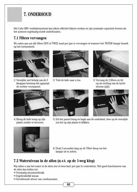
92
7. ONDERHOUD
HetCubeHRVventilatiesysteemkanalleenefficiëntblijvenwerkenenzijnnominalecapaciteitleverenalshet systeem regelmatig wordt onderhouden .
7.1 Filters vervangenWe raden aan om alle filters EEN of TWEE maal per jaar te vervangen of wanneer het 'FILTER'-lampje brandt op het toetsenbord .
7.2 Waterniveau in de sifon (n.v.t. op de 1-weg klep)Wij raden u aan het water in de sifon een of twee keer per jaar te controleren . Niet goed functioneren van de sifon kan leiden tot:•Overmatigstroomverbruik.•Ongebruikelijklawaai.•Onvoldoendeafvoervancondenswater.
2/ Trek de lade naar u toe .
5/Zethetpaneelterugenbeginaandeonderkant,duwopdevoorzijdeomhetopzijnplaatsteklikken.
3/ Vervang de 2 filters en let op de richting van de lucht-stroom (pijl) .
1/ Verwijder met behulp van de 2 knoppen bovenop het apparaat de rechter voorpaneel .
4/Brengdeladeterugopzijnplaatszonderteforceren.
6/ Druk 3 seconden lang op de 'Filter'-knop om het lampjeuittezetten.
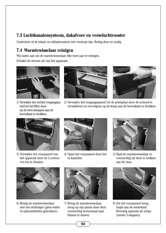
93
7.3 Luchtkanalensysteem, dakafvoer en verseluchtroosterControleerofdeinlaat-enuitlaatroostersnietverstoptzijn.Reinigdezezonodig.
7.4 Warmtewisselaar reinigenWij raden aan om de warmtewisselaar elke twee jaar te reinigen .
Schakel de stroom uit van het apparaat .
2/ Verwijder het toegangspaneel tot de printplaat door de schroef te verwijderen en vervolgens op de knop aan de bovenkant te drukken .
4/ Open het voorpaneel door het te kantelen .
5/ Haal de warmtewisselaar er voorzichtiguitdoortetrekkenaan de riem .
1/ Verwijder het rechter toegangspa-neel tot het filter door op de twee knoppen aan de bovenkant te drukken .
3/ Verwijder het voorpaneel van het apparaat door de 2 schroe-ven los te draaien .
7/ Breng de warmtewisselaar terugopzijnplaatsdoordezevoorzichtighorizontaalnaarbinnen te duwen .
8/Zethetvoorpaneelterug,begin aan de onderkant . Bevestig opnieuw de strips (eerste 3 stappen) .
6/ Reinig de warmtewisselaar meteenstofzuiger(geenwaterof oplosmiddelen gebruiken) .
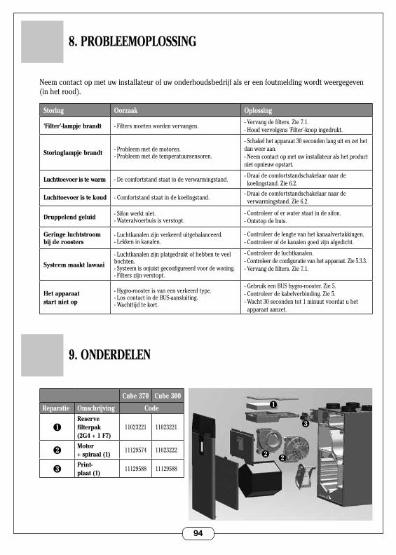
94
8. PROBLEEMOPLOSSING
Neem contact op met uw installateur of uw onderhoudsbedrijf als er een foutmelding wordt weergegeven (in het rood) .
Storing Oorzaak Oplossing
'Filter'-lampje brandt - Filters moeten worden vervangen .- Vervang de filters . Zie 7 .1 . - Houd vervolgens 'Filter'-knop ingedrukt .
Storinglampje brandt - Probleem met de motoren .- Probleem met de temperatuursensoren .
-Schakelhetapparaat30secondenlanguitenzethetdan weer aan .- Neem contact op met uw installateur als het product niet opnieuw opstart .
Luchttoevoer is te warm - De comfortstand staat in de verwarmingstand .- Draai de comfortstandschakelaar naar de
koelingstand . Zie 6 .2 .
Luchttoevoer is te koud - Comfortstand staat in de koelingstand .- Draai de comfortstandschakelaar naar de
verwarmingstand . Zie 6 .2 .
Druppelend geluid - Sifon werkt niet .- Waterafvoerbuis is verstopt .
- Controleer of er water staat in de sifon .- Ontstop de buis .
Geringe luchtstroom bij de roosters
-Luchtkanalenzijnverkeerduitgebalanceerd.- Lekken in kanalen .
- Controleer de lengte van het kanaalvertakkingen .-Controleerofdekanalengoedzijnafgedicht.
Systeem maakt lawaai
-Luchtkanalenzijnplatgedruktofhebbenteveelbochten .- Systeem is onjuist geconfigureerd voor de woning .-Filterszijnverstopt.
- Controleer de luchtkanalen .- Controleer de configuratie van het apparaat . Zie 5 .3 .3 .- Vervang de filters . Zie 7 .1 .
Het apparaat start niet op
- Hygro-rooster is van een verkeerd type .- Los contact in de BUS-aansluiting .- Wachttijd te kort .
- Gebruik een BUS hygro-rooster . Zie 5 .- Controleer de kabelverbinding . Zie 5 .- Wacht 30 seconden tot 1 minuut voordat u het
apparaataanzet.
9. ONDERDELEN
Cube 370 Cube 300
Reparatie Omschrijving Code
1Reserve filterpak (2G4 + 1 F7)
11023221 11023221
2Motor + spiraal (1)
11129574 11023222
3Print- plaat (1)
11129588 11129588
3
2
1
2
95
10. GARANTIE
10.1 Algemene garantievoorwaardenLeesdealgemeneverkoopvoorwaardenoponzewebsitewww.aldes.fr.
Hetsysteemmoetdooreendeskundigevakmanwordengeïnstalleerdinovereenstemmingmetalleregels,normen en voorschriften vervat in de handleidingen . Het systeem moet normaal en regelmatig worden gebruikt en door een vakspecialist worden onderhouden .
10.2 GarantieperiodeHet product heeft een garantie van 2 jaar . De garantie dekt uitsluitend de vervangingsdelen en niet het arbeidsloon .
Degarantiegaatinopdedatumwaarophetproductisgekochtindewinkel;defactuurdientalsbewijsvoordezedatum.
10.3 Uitsluitingen van garantieEventueleinstallatiedefectendiehetgevolgzijnvanniet-nalevingvandevoorschriftenvandefabrikant,niet-naleving van de geldende regelgeving of gebrek aan onderhoud worden niet gedekt door de garantie .
10.4 Technische servicedienst Neem contact op met uw installateur of leverancier ingeval van problemen .
Dit product mag niet worden weggegooid bij het huishoudelijk afval . Bij afdanking of vervangingdooreenanderapparaatmoethetnaareenafvalinzamelingspuntofterugnaareen leverancier worden gebracht .
ALDES is lid van de Franse eco-organisatie 'Eco Systemes' www .ecosystemes .fr .
96 RC
S 95
6 50
6 82
8 - G
edru
ckt i
n Fr
ankr
eich
- 11
0295
79-B
- AL
DES
beh
ält s
ich
das
Rec
ht v
or, a
lle h
ier e
ntha
ltene
n te
chni
sche
n In
form
atio
nen
zu ä
nder
n. D
er In
halt
dies
er A
nlei
tung
kan
n oh
ne V
oran
künd
igun
g ge
ände
rt w
erde
n.
www.aldes.com
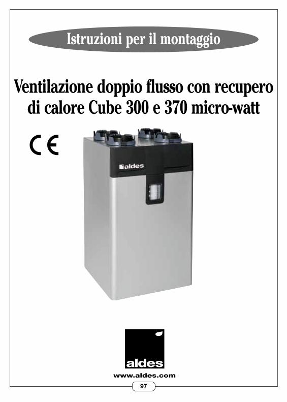
97
Istruzioni per il montaggio
www.aldes.com
Ventilazione doppio flusso con recupero di calore Cube 300 e 370 micro-watt
RC
S 95
6 50
6 82
8 - G
edru
ckt i
n Fr
ankr
eich
- 11
0295
79-B
- AL
DES
beh
ält s
ich
das
Rec
ht v
or, a
lle h
ier e
ntha
ltene
n te
chni
sche
n In
form
atio
nen
zu ä
nder
n. D
er In
halt
dies
er A
nlei
tung
kan
n oh
ne V
oran
künd
igun
g ge
ände
rt w
erde
n.
98
1. INFORMAZIONI GENERALI . . . . . . . . . . . . . . . . . . . . . . . . . . . . . . . . . . . . . p.100 1 .1 Simboli . . . . . . . . . . . . . . . . . . . . . . . . . . . . . . . . . . . . . . . . . . . . . . . . . . . . . . 100 1.2Informazionigenerali . . . . . . . . . . . . . . . . . . . . . . . . . . . . . . . . . . . . . . . . . . 100 1.3Avvertenzeeinformazioniimportanti . . . . . . . . . . . . . . . . . . . . . . . . . . . . 100 1.4Istruzionidisicurezza . . . . . . . . . . . . . . . . . . . . . . . . . . . . . . . . . . . . . . . . . 100 1 .4 .1 Pericoli meccanici . . . . . . . . . . . . . . . . . . . . . . . . . . . . . . . . . . . . . . 100 1 .4 .2 Avvio . . . . . . . . . . . . . . . . . . . . . . . . . . . . . . . . . . . . . . . . . . . . . . . . . 100 1.4.3Utilizzo . . . . . . . . . . . . . . . . . . . . . . . . . . . . . . . . . . . . . . . . . . . . . . . 101 1.4.4Manutenzione . . . . . . . . . . . . . . . . . . . . . . . . . . . . . . . . . . . . . . . . . . 101 1.4.5Trasformazione . . . . . . . . . . . . . . . . . . . . . . . . . . . . . . . . . . . . . . . . 101 1 .4 .6 Fine vita . . . . . . . . . . . . . . . . . . . . . . . . . . . . . . . . . . . . . . . . . . . . . . . 101 1 .5 Trasporto e stoccaggio . . . . . . . . . . . . . . . . . . . . . . . . . . . . . . . . . . . . . . . . 102 1.6Trasportoconcarrelloelevatore(conosenzaforche) . . . . . . . . . . . . . 102 1 .7 Trasporto manuale . . . . . . . . . . . . . . . . . . . . . . . . . . . . . . . . . . . . . . . . . . . . 102
2. PRINCIPI OPERATIVI . . . . . . . . . . . . . . . . . . . . . . . . . . . . . . . . . . . . . . . . . . . . 103 2.1Sistemadiventilazioneconrecuperodicalore . . . . . . . . . . . . . . . . . . . . 103 2.2Posizionamento . . . . . . . . . . . . . . . . . . . . . . . . . . . . . . . . . . . . . . . . . . . . . . 103
3. DESCRIZIONE . . . . . . . . . . . . . . . . . . . . . . . . . . . . . . . . . . . . . . . . . . . . . . . . . . . 104 3 .1 Dati tecnici . . . . . . . . . . . . . . . . . . . . . . . . . . . . . . . . . . . . . . . . . . . . . . . . . . 104 3 .2 Consumo energetico . . . . . . . . . . . . . . . . . . . . . . . . . . . . . . . . . . . . . . . . . . 104 3 .3 Dimensioni . . . . . . . . . . . . . . . . . . . . . . . . . . . . . . . . . . . . . . . . . . . . . . . . . . . 105
4. INSTALLAZIONE . . . . . . . . . . . . . . . . . . . . . . . . . . . . . . . . . . . . . . . . . . . . . . . . . 106 4.1Localediinstallazione . . . . . . . . . . . . . . . . . . . . . . . . . . . . . . . . . . . . . . . . . 106 4.2Tipodiinstallazione . . . . . . . . . . . . . . . . . . . . . . . . . . . . . . . . . . . . . . . . . . . 106 4 .3 Connessione aeraulica . . . . . . . . . . . . . . . . . . . . . . . . . . . . . . . . . . . . . . . . . 108 Impianto di condotti aeraulici . . . . . . . . . . . . . . . . . . . . . . . . . . . . . . . . 108 Tipodiuscitaatettoegrigliad'arianuovadautilizzare . . . . . . . . . 108 Divario di ricircolo . . . . . . . . . . . . . . . . . . . . . . . . . . . . . . . . . . . . . . . . . . 109 Connessione all'apparecchio . . . . . . . . . . . . . . . . . . . . . . . . . . . . . . . . . 109 4 .4 Connessione elettrica . . . . . . . . . . . . . . . . . . . . . . . . . . . . . . . . . . . . . . . . . 110 Collegamento alla rete elettrica . . . . . . . . . . . . . . . . . . . . . . . . . . . . . . . 110 Opzione:pulsantecucina/BOOSTdelcontrollodeltassodiflusso . . . . . . . . . . .110 Collegamenti specifici per controllo dell’umidità . . . . . . . . . . . . . . . . 111 4 .5 Drenaggio della condensa . . . . . . . . . . . . . . . . . . . . . . . . . . . . . . . . . . . . . . 112
SOMMARIO
99
5. AVVIO . . . . . . . . . . . . . . . . . . . . . . . . . . . . . . . . . . . . . . . . . . . . . . . . . . . . . . . . . 113 5 .1 Controlli importanti prima dell'avvio . . . . . . . . . . . . . . . . . . . . . . . . . . . . 113 5.2Accessoaltastierinodiconfigurazione . . . . . . . . . . . . . . . . . . . . . . . . . . 113 5.3Impostazionidifabbrica . . . . . . . . . . . . . . . . . . . . . . . . . . . . . . . . . . . . . . . 114 5.4Regolazionedelleimpostazioni . . . . . . . . . . . . . . . . . . . . . . . . . . . . . . . . . 114
6. UTILIZZO . . . . . . . . . . . . . . . . . . . . . . . . . . . . . . . . . . . . . . . . . . . . . . . . . . . . . . . 115 6.1Regolazionedeltassodiventilazione . . . . . . . . . . . . . . . . . . . . . . . . . . . . 115 6.2Selezionedellamodalitàcomfort . . . . . . . . . . . . . . . . . . . . . . . . . . . . . . . . 115
7. MANUTENZIONE . . . . . . . . . . . . . . . . . . . . . . . . . . . . . . . . . . . . . . . . . . . . . . . . 116 7.1Sostituzionedeifiltri . . . . . . . . . . . . . . . . . . . . . . . . . . . . . . . . . . . . . . . . . . 116 7 .2 Livello del sifone . . . . . . . . . . . . . . . . . . . . . . . . . . . . . . . . . . . . . . . . . . . . . . 116 7 .3 Impianto di condotti aeraulici, uscita a tetto e griglia aria nuova . . . . 117 7 .4 Pulire lo scambiatore . . . . . . . . . . . . . . . . . . . . . . . . . . . . . . . . . . . . . . . . . . 117
8. RISOLUZIONE DEI PROBLEMI . . . . . . . . . . . . . . . . . . . . . . . . . . . . . . . . . . . . . 118
9. RICAMBI . . . . . . . . . . . . . . . . . . . . . . . . . . . . . . . . . . . . . . . . . . . . . . . . . . . . . . . 118
10. GARANZIA . . . . . . . . . . . . . . . . . . . . . . . . . . . . . . . . . . . . . . . . . . . . . . . . . . . . . 119 10.1Condizionigeneralidellagaranzia . . . . . . . . . . . . . . . . . . . . . . . . . . . . . . 119 10.2Duratadellagaranzia . . . . . . . . . . . . . . . . . . . . . . . . . . . . . . . . . . . . . . . . . 119 10.3Esclusionidallacoperturadigaranzia . . . . . . . . . . . . . . . . . . . . . . . . . . 119 10.4Serviziopost-vendita . . . . . . . . . . . . . . . . . . . . . . . . . . . . . . . . . . . . . . . . . 119
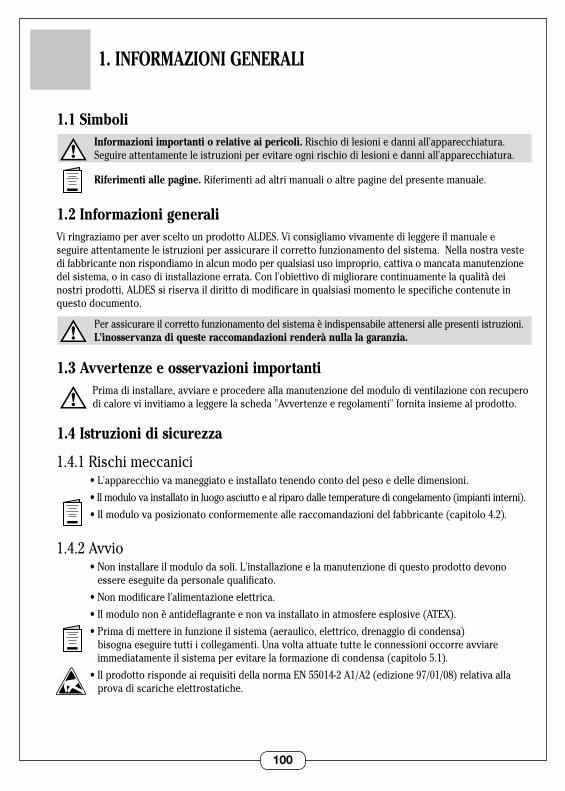
100
1.1 Simboli Informazioni importanti o relative ai pericoli. Rischio di lesioni e danni all'apparecchiatura . Seguireattentamenteleistruzioniperevitareognirischiodilesioniedanniall'apparecchiatura.
Riferimenti alle pagine. Riferimenti ad altri manuali o altre pagine del presente manuale .
1.2 Informazioni generaliViringraziamoperaversceltounprodottoALDES.Viconsigliamovivamentedileggereilmanualee seguireattentamenteleistruzioniperassicurareilcorrettofunzionamentodelsistema.Nellanostravestedifabbricantenonrispondiamoinalcunmodoperqualsiasiusoimproprio,cattivaomancatamanutenzione delsistema,oincasodiinstallazioneerrata.Conl'obiettivodimigliorarecontinuamentelaqualitàdeinostri prodotti, ALDES si riserva il diritto di modificare in qualsiasi momento le specifiche contenute in questo documento .
Perassicurareilcorrettofunzionamentodelsistemaèindispensabileattenersiallepresentiistruzioni. L'inosservanza di queste raccomandazioni renderà nulla la garanzia.
1.3 Avvertenze e osservazioni importanti Primadiinstallare,avviareeprocedereallamanutenzionedelmodulodiventilazioneconrecupero
dicaloreviinvitiamoaleggerelascheda"Avvertenzeeregolamenti"fornitainsiemealprodotto.
1.4 Istruzioni di sicurezza
1 .4 .1 Rischi meccanici •L'apparecchiovamaneggiatoeinstallatotenendocontodelpesoedelledimensioni.
•Ilmodulovainstallatoinluogoasciuttoealriparodalletemperaturedicongelamento(impiantiinterni).
•Ilmodulovaposizionatoconformementealleraccomandazionidelfabbricante(capitolo4.2).
1 .4 .2 Avvio •Noninstallareilmodulodasoli.L'installazioneelamanutenzionediquestoprodottodevono
essere eseguite da personale qualificato .
•Nonmodificarel'alimentazioneelettrica.
•Ilmodulononèantideflagranteenonvainstallatoinatmosfereesplosive(ATEX).
•Primadimettereinfunzioneilsistema(aeraulico,elettrico,drenaggiodicondensa)bisogna eseguire tutti i collegamenti . Una volta attuate tutte le connessioni occorre avviare immediatamenteilsistemaperevitarelaformazionedicondensa(capitolo5.1).
•IlprodottorispondeairequisitidellanormaEN55014-2A1/A2(edizione97/01/08)relativaallaprova di scariche elettrostatiche .
1. INFORMAZIONI GENERALI
101
1.4.3Utilizzo •Incasodidisfunzioneocattivofunzionamentorivolgersiaunprofessionista.
•Nonintrodurrecorpiestraneinellegrigliediimmissioneediestrazionedell'aria.
•Ilsistemadicircolazionedell'ariadeveessereperfettamentesgombro.
•Nonarrampicarsisultelaiodell'apparecchio.
•Ilvostrolocalerispondeadiversenormedisicurezzachenondevonoesseremodificate(ventilazione,condottidievacuazionefumi,aperture,ecc.)senzachiedereilpreviopareredell'installatore.
1.4.4Manutenzione •Nontentarediripararel'apparecchiodasoli.
•Nessunelementodell'apparecchiopuòessereriparatodall'utente.Larimozionediqualsiasi coperchio vi espone a pericolosi voltaggi .
•Nonbastainterromperel'alimentazioneelettricaperscongiurareilrischiodifolgorazione(condensatori) .
•Interrompereimmediatamentelacorrenteelettricaincasodirumoriabnormi,odoriopresenzadifumi e contattare l’installatore .
•Primadipulirel'apparecchio,interromperel'alimentazioneelettrica.
•Nonutilizzaredetersiviliquidiosolventiaggressivisull'apparecchio.
•Perpulirelegriglied'arianonutilizzarepulitoriadacquaapressione.Sirischierebbedidanneggiare lo scambiatore d'aria e lasciare che l'acqua venga a contatto con i circuiti elettrici .
1 .4 .5 Modifiche •Èseveramentevietatomodificarel'apparecchio.Lasostituzionedeiricambivaeseguitada
personale qualificato che si serve unicamente di ricambi originali forniti dal fabbricante .
1 .4 .6 Fine vita •Primadismontarel'apparecchiointerromperel'alimentazioneelettrica.
•Lacombustioneditalunicomponentipuòrilasciaregastossici:nonincenerirel'apparecchio.
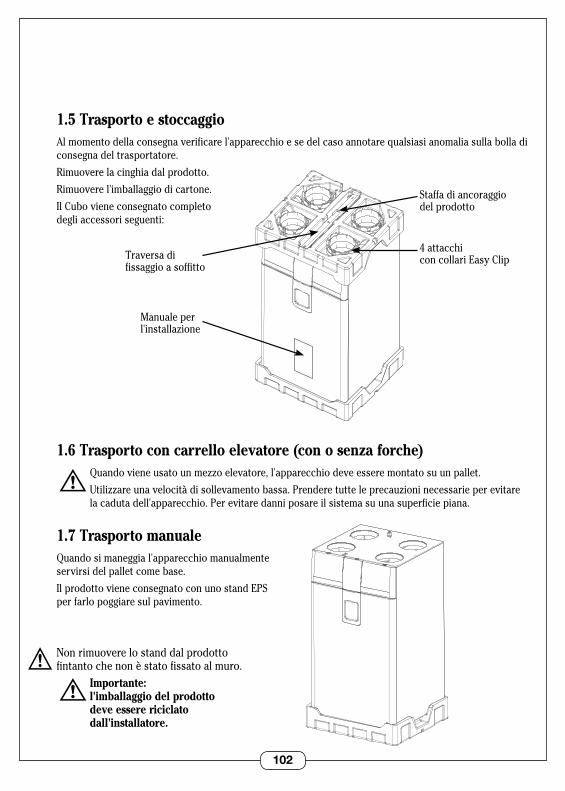
102
1.5 Trasporto e stoccaggioAl momento della consegna verificare l'apparecchio e se del caso annotare qualsiasi anomalia sulla bolla di consegna del trasportatore .
Rimuovere la cinghia dal prodotto .
Rimuovere l'imballaggio di cartone .
Il Cubo viene consegnato completo degli accessori seguenti:
1.6 Trasporto con carrello elevatore (con o senza forche) Quandovieneusatounmezzoelevatore,l'apparecchiodeveesseremontatosuunpallet.
Utilizzareunavelocitàdisollevamentobassa.Prenderetutteleprecauzioninecessarieperevitare la caduta dell'apparecchio . Per evitare danni posare il sistema su una superficie piana .
1.7 Trasporto manualeQuando si maneggia l'apparecchio manualmente servirsi del pallet come base .
Il prodotto viene consegnato con uno stand EPS per farlo poggiare sul pavimento .
Non rimuovere lo stand dal prodotto fintanto che non è stato fissato al muro . Importante: l'imballaggio del prodotto deve essere riciclato dall'installatore.
VUE 3/4 AVANT BARQUETTE DESSUS
4 attacchi con collari Easy Clip
Manuale per l'installazione
Staffa di ancoraggio del prodotto
Traversa di fissaggio a soffitto
VUE 3/4 AVANT BARQUETTE DESSOUS
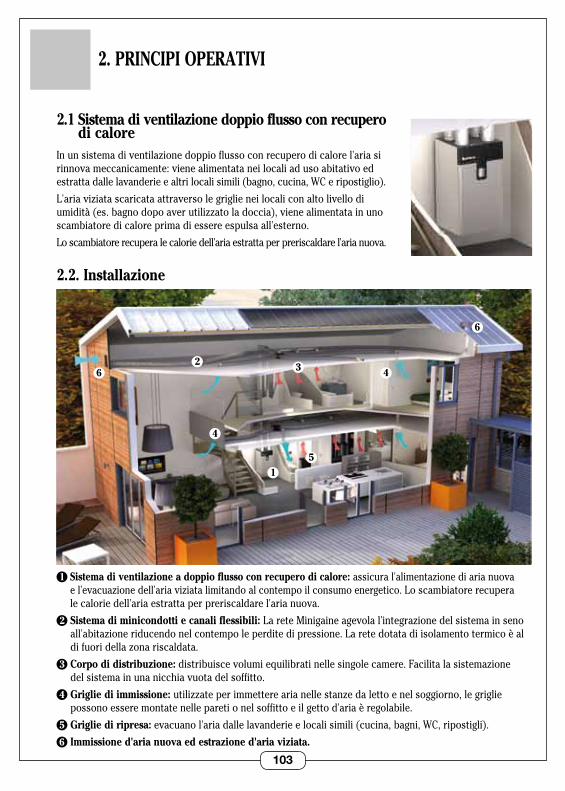
103
2. PRINCIPI OPERATIVI
62
6
1
4
4
5
3
2.1 Sistema di ventilazione doppio flusso con recupero di calore
Inunsistemadiventilazionedoppioflussoconrecuperodicalorel'ariasirinnova meccanicamente: viene alimentata nei locali ad uso abitativo ed estratta dalle lavanderie e altri locali simili (bagno, cucina, WC e ripostiglio) .
L'ariaviziatascaricataattraversolegriglieneilocaliconaltolivellodiumidità(es.bagnodopoaverutilizzatoladoccia),vienealimentatainunoscambiatore di calore prima di essere espulsa all'esterno .
Lo scambiatore recupera le calorie dell'aria estratta per preriscaldare l'aria nuova .
2.2. Installazione
1 Sistema di ventilazione a doppio flusso con recupero di calore: assicural'alimentazionediarianuova el'evacuazionedell'ariaviziatalimitandoalcontempoilconsumoenergetico. Lo scambiatore recupera le calorie dell'aria estratta per preriscaldare l'aria nuova .
2 Sistema di minicondotti e canali flessibili: LareteMinigaineagevolal'integrazionedelsistemainsenoall'abitazioneriducendonelcontempoleperditedipressione.Laretedotatadiisolamentotermicoèaldifuoridellazonariscaldata.
3 Corpo di distribuzione:distribuiscevolumiequilibratinellesingolecamere.Facilitalasistemazione del sistema in una nicchia vuota del soffitto .
4 Griglie di immissione: utilizzateperimmetterearianellestanzedalettoenelsoggiorno,legriglie possono essere montate nelle pareti o nel soffitto e il getto d'aria è regolabile .
5 Griglie di ripresa: evacuano l'aria dalle lavanderie e locali simili (cucina, bagni, WC, ripostigli) .
6 Immissione d'aria nuova ed estrazione d'aria viziata.
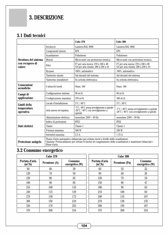
104
3.1 Dati tecniciCube 370 Cube 300
Struttura del sistema con recupero di calore
Involucro LamieraRAL9006 LamieraRAL9006
Componenti interni EPS EPS
Scambiatore Polistirene Polistirene
Motori Micro-wattconprotezionetermica Micro-wattconprotezionetermica
Filtri F7perarianuova:270x240x48 G4perariaviziata:280x240x10
F7perarianuova:270x240x48 G4perariaviziata:280x240x10
By-pass 100%, automatico 100%, automatico
Tastierino utente Sul davanti del sistema Sul davanti del sistema
Tastierino installatore Su scheda elettronica Su scheda elettronica
Connessioni aerauliche 4 attacchi tondi Diam . 160 Diam . 160
Campi di applicazione
Configurazioneminima 90m3/h 60 m3/h
Configurazionemassima 370 m3/h 300 m3/h
Limiti della temperatura operativa
Localed'installazione 5°C / 60°C 5°C / 60°C
Aria nuova ed espulsa-7°C/40°Csenzaavvolgimentoaspirale -20°C / 40°C con avvolgimento a spirale
-7°C/40°Csenzaavvolgimentoaspirale -20°C / 40°C con avvolgimento a spirale
Dati elettrici
Alimentazioneelettrica monofase230V–50Hz monofase230V–50Hz
Indicediprotezione IPX2 IPX2
Classe Classe 1 Classe 1
Potenzamassima 340 W 230 W
Intensità massima 2,5 A 1,75 A
Protezione antigeloFlusso d'aria automatico sbilanciato per evitare rischi a livello dello scambiatore . Opzione:Preriscaldatoreperevitareilrischiodicongelamentodelloscambiatoreemantenerebilanciatiiflussi d'aria .
3.2 Consumo energetico
3. DESCRIZIONE
Cube 370
Portata d'aria (m3/h) Pressione (A) Consumo
energetico (W)90 60 39
120 70 50150 80 65180 90 85210 100 110240 115 139270 130 172300 150 210330 170 253370 200 316
Cube 300
Portata d'aria (m3/h) Pressione (Pa) Consumo
energetico (W)60 55 2290 60 26
120 70 34150 80 47180 90 63210 100 83240 115 107270 130 135300 150 167370 200 316
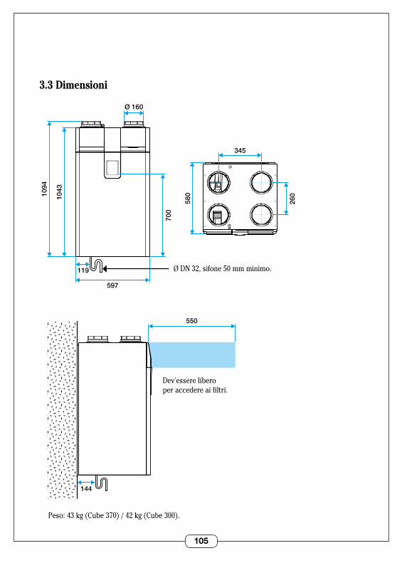
105
3.3 Dimensioni
1094
1043
597
119
580
700
345
Ø 160
260
144
550
Ø DN 32, sifone 50 mm minimo .
Dev'essere liberoper accedere ai filtri .
Peso: 43 kg (Cube 370) / 42 kg (Cube 300) .
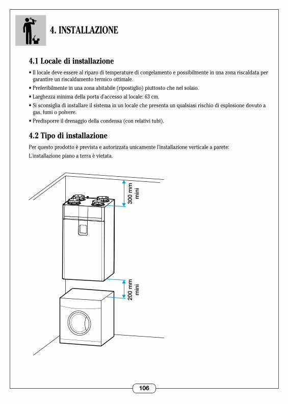
106
4. INSTALLAZIONE
4.1 Locale di installazione•Illocaledeveesserealriparoditemperaturedicongelamentoepossibilmenteinunazonariscaldataper
garantire un riscaldamento termico ottimale .
•Preferibilmenteinunazonaabitabile(ripostiglio)piuttostochenelsolaio.
•Larghezzaminimadellaportad'accessoallocale:63cm.
•Sisconsigliadiinstallareilsistemainunlocalechepresentaunqualsiasirischiodiesplosionedovutoagas, fumi o polvere .
•Predisporreildrenaggiodellacondensa(conrelativitubi).
4.2 Tipo di installazionePerquestoprodottoèprevistaeautorizzataunicamentel'installazioneverticaleaparete:
L'installazionepianoaterraèvietata.
200
mm
min
i30
0 m
mm
ini
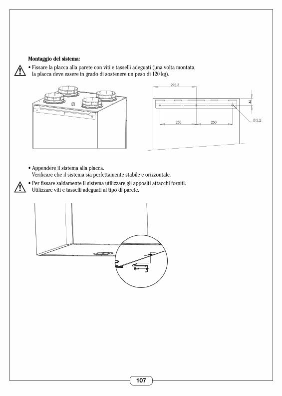
107
Montaggio del sistema:
•Fissarelaplaccaallapareteconvitietasselliadeguati(unavoltamontata, la placca deve essere in grado di sostenere un peso di 120 kg) .
•Appendereilsistemaallaplacca. Verificarecheilsistemasiaperfettamentestabileeorizzontale.
•Perfissaresaldamenteilsistemautilizzaregliappositiattacchiforniti. Utilizzarevitietasselliadeguatialtipodiparete.
5,2
46
250 250
298,3
VUE ARRIERE SUPPORT MURAL
5,2
46
250 250
298,3
VUE ARRIERE SUPPORT MURAL
VUE 3/4 DESSOUS EQUERRE MURALE
VUE 3/4 DESSOUS EQUERRE MURALE
108
Connessioni aerauliche
Tipo di sistema di condotti aeraulici L'apparecchiopuòessereutilizzatocondiversitipidicondotti:
•CondottiflessibiliAlgaine.(prevedereunisolamentodialmeno50mmseinstallatoinzonenonriscaldate).
•CondottirigidiMinigaine(soloinzoneriscaldate).
•Condottisemi-rigidiFlexigaine(soloinzoneriscaldate).
Raccomandazioni per il posizionamento dei condotti: •Icondottiflessibilidevonoesseresospesi. •Evitarepiegheinutili. •Accertarsicheicondottinonsianoschiacciati.
Scelta del tipo di uscita a tetto e griglia per aria nuova Per ridurre al massimo le perdite di pressione, occorre procedere nel modo seguente:
Espulsionedell'ariaviziata:•Tramiteun'uscitaatettodidiametro160,deltipostandardSTS.•OppuretramiteunagrigliaapareteesternadeltipoAWA251300x300.
Immissione dell'aria nuova:•GrigliaapareteesternadeltipoAWA251300x300.
Labocchettad'immissionediarianuovaequellad'estrazionedell'ariaviziatadevonoessereinstallatein 2sezionidifferentidipareteoalmenoaunadistanzadi8metril'unadall'altraperevitareilricircolo.
Lagrigliavasistematainmododaevitarechesibagniovengaintasata.Posizionareconcura(lontanodacamini o parcheggi) .
L'uscita a tetto e la bocchetta di immissione d'aria nuova devono essere collegate ai condotti del sistema di un diametro di 160 mm . Si sconsiglia di sistemare la bocchetta di immissione d'aria nuova sul tetto (rischio di arrivo d'acqua o di neve nel sistema di recupero di calore) .
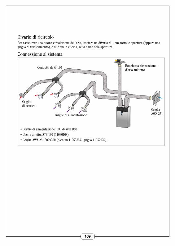
109
Divario di ricircoloPerassicurareunabuonacircolazionedell'aria,lasciareundivariodi1cmsottoleaperture(oppureuna griglia di trasferimento), e di 2 cm in cucina, se vi è una sola apertura .
Connessione al sistema
Grigliedialimentazione
•Grigliedialimentazione:BIOdesignD80.
•Uscitaatetto:STS160(11030108).
•GrigliaAWA251300x300(plenum11053757+griglia11052039).
Griglie di scarico
Condotti da Ø 160 Bocchettad'estrazioned'aria sul tetto
Griglia AWA 251

110
4.4 - Connessioni elettriche
Collegamento alla rete elettricaIl cablaggio del sistema deve essere eseguito da personale professionista familiare con lo standard locale del paese . Collegareilcavofornitoallareteelettricautilizzando unacassettadiderivazionestagna(nonfornita).
Sezionetrasversaledelcavo:3x1.5mm2 .
Alimentazioneelettrica:correntealternata230Vmonofase.L'impianto deve comportare:•uninterruttorebipolare.
•unaprotezionetramiteinterruttoredifferenziale con rating 30 mA .
Opzione:pulsantecucina/BOOSTdelcontrollodiportataÈpossibileinstallareincucinaunpulsanteperiseguenticontrolli:•Pressionebreve:perpassaredallavelocità2allavelocità3(nientetimer).•Pressionedi3secondi:perpassaredallavelocità3allavelocità4(nientetimer).•Premendoancoraunavoltasiripristinalavelocità2.
Per rimuovere il pannello di accesso del filtro destro premere i due pulsanti in alto .
Rimuovere il pannello di accesso alla scheda elettronica rimuovendo la vite e poi premendo il pulsante in alto .
VUE 3/4 DESSUS SORTIE CORDON
connettore 230V . Lunghezzadicavo disponibile: 1 m
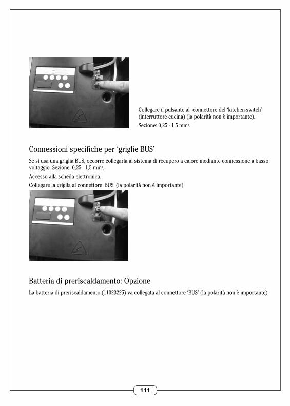
111
Collegare il pulsante al connettore del ‘kitchen-switch’ (interruttore cucina) (la polarità non è importante) .
Sezione:0,25-1,5mm2 .
Connessioni specifiche per ‘griglie BUS’Se si usa una griglia BUS, occorre collegarla al sistema di recupero a calore mediante connessione a basso voltaggio.Sezione:0,25-1,5mm2 .
Accesso alla scheda elettronica .
Collegare la griglia al connettore 'BUS' (la polarità non è importante) .
Batteriadipreriscaldamento:OpzioneLa batteria di preriscaldamento (11023225) va collegata al connettore ‘BUS’ (la polarità non è importante) .
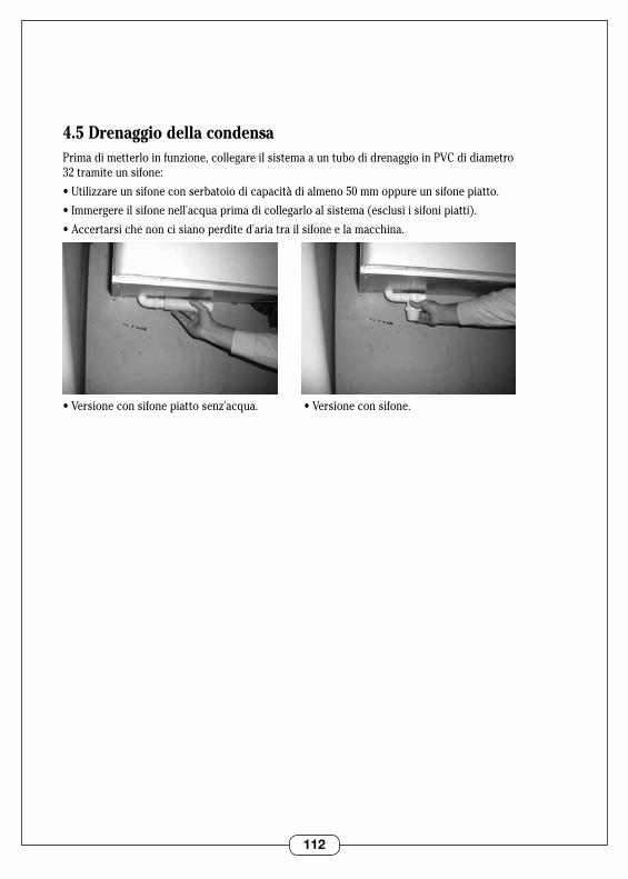
112
4.5 Drenaggio della condensaPrimadimetterloinfunzione,collegareilsistemaauntubodidrenaggioinPVCdidiametro 32 tramite un sifone:
•Utilizzareunsifoneconserbatoiodicapacitàdialmeno50mmoppureunsifonepiatto.
•Immergereilsifonenell'acquaprimadicollegarloalsistema(esclusiisifonipiatti).
•Accertarsichenoncisianoperdited'ariatrailsifoneelamacchina.
•Versioneconsifonepiattosenz'acqua.•Versioneconsifone.
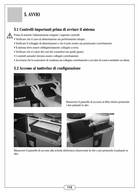
113
5. AVVIO
5.1 Controlli importanti prima di avviare il sistemaPrimadiinserirel'alimentazioneeseguireiseguenticontrolli:
•Verificarecheilcavodialimentazionesiaperfettamenteintegro.
•Verificareilvoltaggiodialimentazioneecheilpoloneutrosiaposizionatocorrettamente.
•Ilsistemadeveessereobbligatoriamentecollegatoaterra.
•Verificarecheilcoloredeicavideiconnettorisiaquellogiusto.
•Icondottiaeraulicidevonoesserecollegaticorrettamente.
•Accertarsicheloscaricatoredicondensasiacollegatocorrettamenteauntubodiscaricomedianteunsifone.
5.2 Accesso al tastierino di configurazione
Rimuovere il pannello di accesso al filtro destro premendo i due pulsanti in alto .
Rimuovere il pannello di accesso alla scheda elettronica rimuovendo la vite e poi premendo il pulsante in alto .

114
5.3 Impostazioni di fabbricaIl sistema è configurato con le seguenti impostazionididefault:
5.4 Regolazione delle impostazioniAccenderel'alimentazionedelsistemaA volte bisogna attendere da 30 secondi a 1 minuto prima che i motori si mettano in moto .
1.Premereilpulsanteinaltoperselezionare il tipo di sistema desiderato: •Modalitàportatad'ariacostante(ventilatorediestrazione
e immissione del flusso d'aria bilanciato) .
•Ventilatorediestrazioneapressionecostanteeventilatoredi immissione bilanciato elettronicamente .
2 . I pulsanti in basso servono a configurare il sistema in funzionedell'abitazione:
a.Selezionarelavelocitàdaimpostare.
b . Con e regolare il flusso d'aria (modalità flusso d'aria costante), o la pressione necessaria (modalità pressione costante) .
3 . Se necessario, regolare il bilanciamento tra i due motori
a . Premere contemporaneamente i pulsanti ‘velocità2’+ + .
b . Regolare il tasso di squilibrio tra il motore di espulsione e quello di immissione .
4.Ripristinodelleimpostazionididefault:
a . Premere contemporaneamente ‘velocità 2’ + + .
b . Premere o per ripristinare a 0 .
ModalitàFlusso d’aria
costantePressione costante
Velocità 1 100 50
Velocità 2 120 100
Velocità 3 210 120
Velocità 4 240 140

115
6. UTILIZZO
Permodificare2parametrisipuòutilizzareiltastierinoutente:
6.1 Regolazione della portata di ventilazione1.Modalitàassenza(velocità1):dautilizzarequandocisiassentadacasaperperiodiprolungati
(vacanze)-nontemporizzato. Lamodalitàassenzariducelaportatadiventilazionepermantenerlaaunlivellominimo.
2.Flussodiportatanominale(velocità2):portataventilazionedidefault-nontemporizzata.
3.Aumentodellaportata(velocità3):riportalavelocitàdelflussod'ariaalvaloreimpostato-senzatimer .
4.BOOSTdellaportata(velocità4):riportalavelocitàdellaportataalvaloreimpostato-senzatimer.
6.2 Selezione della modalità comfort 1.Modoautomatico.Perottimizzareilsistemadirecuperodicaloresiusailbypassestivodelloscambia-
toredicalorepermantenerel'abitazionecaldad'invernoefrescad'estate.
2.Modalitàriscaldamento:ilsistemafornisceall'abitazioneariacaldasiad'estateched'inverno.
3 . Modalità raffrescamento: il sistema fornisce all'ambiente aria fresca sia d'estate che d'inverno .
0
SDBType Logement
CellierWC
1 2 3 4 5/6/7
Hygro
Auto
0
SDBType Logement
CellierWC
1 2 3 4 5/6/7
Hygro
Auto
Portata dellaventilazione
Modalità comfort
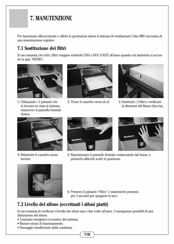
116
7. MANUTENZIONE
PerfunzionareefficacementeeoffrireleprestazioniatteseilsistemadiventilazioneCubeHRVnecessitadiunamanutenzioneregolare.
7.1 Sostituzione dei filtriSi raccomanda che tutti i filtri vengano sostituiti UNA o DUE VOLTE all'anno quando sul tastierino si accen-de la spia "FILTRO" .
7.2 Livello del sifone (eccettuati i sifoni piatti)Siraccomandadiverificareillivellodeisifoniunaoduevolteall'anno.Conseguenzepossibilidiuna disfunzionedelsifone:•Consumoenergeticoeccessivodelsistema.•Rumoristranidifunzionamento.•Drenaggioinsufficientedellacondensa.
2/ Tirare il cassetto verso di sé .
5/Riposizionareilpannellofrontalecominciandodalbasso,e premerloaffinchéscattiinposizione.
3/ Sostituire i 2 filtri e verificare ladirezionedelflusso(freccia).
1/Utilizzandoi2pulsantichesi trovano in cima al sistema, rimuovere il pannello frontale destro .
4/Reinserireilcassettosenzaforzare.
6/ Premere il pulsante “Filtro” e mantenerlo premuto per 3 secondi per spegnere la luce .

117
7.3 Sistema di condotti aeraulici, uscita a tetto e griglia aria nuovaVerificarechelegrigliediimmissioneediestrazionenonsianointasate.Sesonointasate,pulirle.
7.4 Pulire lo scambiatoreSi raccomanda di pulire lo scambiatore ogni due mesi .
Spegnerel'alimentazionedelsistema.
2/ Rimuovere il panello di accesso alla scheda elettronica rimuovendo la vite e premendo poi il pulsante in alto .
4/ Aprire il portello frontale inclinandolo .
5/ Estrarre lo scambiatore tirando delicatamente la cinghia .
1/ Rimuovere il pannello di accesso al filtro destro premendo i due pulsanti in alto .
3/ Rimuovere il pannello frontale del sistema svitando le 2 viti .
7/Riposizionareloscambiatoresospingendolo delicatamente insensoorizzontale.
8/Riposizionareilpannello frontale inserendolo in basso, quindi riallacciare le cinghie (primi 3 passi) .
6/ Pulire lo scambiatore con un aspirapolvere (non usare acqua o solventi) .
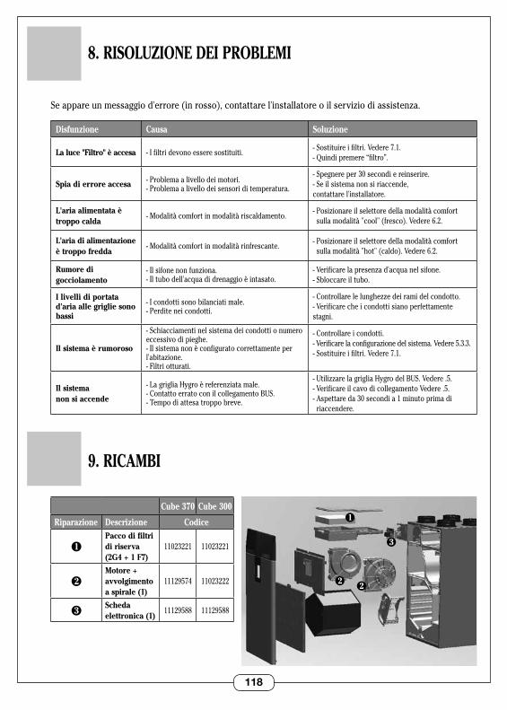
118
8. RISOLUZIONE DEI PROBLEMI
Seappareunmessaggiod'errore(inrosso),contattarel'installatoreoilserviziodiassistenza.
Disfunzione Causa Soluzione
La luce "Filtro" è accesa - I filtri devono essere sostituiti .- Sostituire i filtri . Vedere 7 .1 . - Quindi premere “filtro” .
Spia di errore accesa - Problema a livello dei motori .- Problema a livello dei sensori di temperatura .
- Spegnere per 30 secondi e reinserire .- Se il sistema non si riaccende, contattare l'installatore .
L'aria alimentata è troppo calda
- Modalità comfort in modalità riscaldamento .-Posizionareilselettoredellamodalitàcomfort
sulla modalità "cool" (fresco) . Vedere 6 .2 .
L'aria di alimentazione è troppo fredda
- Modalità comfort in modalità rinfrescante .-Posizionareilselettoredellamodalitàcomfort
sulla modalità "hot" (caldo) . Vedere 6 .2 .
Rumore di gocciolamento
-Ilsifonenonfunziona.- Il tubo dell'acqua di drenaggio è intasato .
-Verificarelapresenzad'acquanelsifone.- Sbloccare il tubo .
I livelli di portata d'aria alle griglie sono bassi
- I condotti sono bilanciati male .- Perdite nei condotti .
-Controllarelelunghezzedeiramidelcondotto.- Verificare che i condotti siano perfettamente stagni .
Il sistema è rumoroso
- Schiacciamenti nel sistema dei condotti o numero eccessivo di pieghe .- Il sistema non è configurato correttamente per l'abitazione.- Filtri otturati .
- Controllare i condotti .-Verificarelaconfigurazionedelsistema.Vedere5.3.3.- Sostituire i filtri . Vedere 7 .1 .
Il sistema non si accende
-LagrigliaHygroèreferenziatamale.- Contatto errato con il collegamento BUS .- Tempo di attesa troppo breve .
-UtilizzarelagrigliaHygrodelBUS.Vedere.5.- Verificare il cavo di collegamento Vedere .5 .- Aspettare da 30 secondi a 1 minuto prima di
riaccendere .
9. RICAMBI
Cube 370 Cube 300
Riparazione Descrizione Codice
1Pacco di filtri di riserva (2G4 + 1 F7)
11023221 11023221
2Motore + avvolgimento a spirale (1)
11129574 11023222
3Scheda elettronica (1)
11129588 11129588
3
2
1
2
119
10. GARANZIA
10.1 Condizioni generali della garanziaViinvitiamoaprendereconoscenzadellecondizionigeneralidivenditasulnostrositowebwww.aldes.fr.
Il sistema deve essere installato da personale qualificato in conformità con i regolamenti, gli standard eleraccomandazionicontenutineimanuali.Ilsistemadeveessereutilizzatonormalmenteelasuamanutenzionevaaffidataadunospecialista.
10.2 Periodo di garanziaIlprodottoècopertodaunagaranziadidueanni.Lagaranziacopreunicamenteiricambimaescludeillavoro .
Lagaranziaprendeeffettoalmomentodell'acquistodelprodottonelnegozio,alladatachefigurasullarela-tiva fattura .
10.3 Esclusioni dalla copertura di garanziaSonoesclusidallacoperturadigaranziaidifettidiinstallazioneconseguentiall'inosservanzadelleraccomandazionidelfabbricante,all'inosservanzadellenormativevigentieaunamanutenzionescarsaoinesistente .
10.4 Servizio post-vendita In caso di problema si prega di contattare l'installatore o il rivenditore .
Questo prodotto non va smaltito insieme ai rifiuti domestici . Arrivato a fine vita o in caso disostituzione,bisognaconsegnarloauncentrodiraccoltaoppurerenderloalrivenditore.
ALDES è membro del sistema collettivo francese Eco Systemes: www .ecosystemes .fr .
120 RCS
956
506
828
- Sta
mpa
to in
Fra
ncia
- 11
0295
79-B
- AL
DES
si r
iserv
a il d
iritto
di m
odific
are
qual
siasi
info
rmaz
ione
tecn
ica
ivi c
onte
nuta
. Il c
onte
nuto
del
le p
rese
nti is
truzio
ni p
uò e
sser
e m
odific
ato
in o
gni m
omen
to s
enza
pre
avvis
o.
www.aldes.com