
Counter-Rotating Open Rotor (CROR): ow physics and simulation
6
20 ` eme Congr` es Fran¸ cais de M´ ecanique Besan¸ con, 29 aoˆ ut au 2 septembre 2011 Counter-Rotating Open Rotor (CROR): flow physics and simulation Laurence Vion a , Gr´ egory Delattre b , Fabrice Falissard c , Laurent Jacquin d a. Snecma, Rond Point Ren´ e Raveau, R´ eau 75550 Moissy-Cramayel [email protected] b. Onera - D´ epartement d’A´ erodynamique Appliqu´ ee 8 Rue des Vertugadins 92190 Meudon c. Onera - D´ epartement de Simulation Num´ erique des Ecoulements et A´ eroacoustique 29 Avenue de la Division Leclerc 92322 Chˆatillon d. Onera - D´ epartement d’A´ erodynamique Fondamentale et Exp´ erimentale 8 Rue des Vertugadins 92190 Meudon R´ esum´ e: La propulsion par h´ elices contrarotatives est `a l’´ etude dans le contexte des recherches men´ ees sur la r´ eduction de la consommation et du bruit a´ eronautiques. Dans un Open Rotor, on cherche notamment `amaˆ ıtriser la nappe tourbillonnaire issue de l’h´ elice amont car elle vient impacter l’h´ elice aval, contri- buant majoritairement au bruit rayonn´ e. Des simulations avanc´ ees de ce probl` eme seront pr´ esent´ ees et discut´ ees sur le plan de la m´ ecanique des fluides et de l’acoustique. Abstract: Counter-rotating open rotor are currently being investigated within the frame of aircraft fuel burn and noise reduction. The vortex sheet shed by the front propeller interacts with the downstream blades, resulting in periodic fluctuations in the aft rotor blades forces. This interaction is a significant noise source and the study of this mechanism is required as a part of the design process for the next generation of open rotor. CFD computations of this problem have been performed and results are discussed from aerodynamic and aeroacoustic points of view. Mots clefs : Open Rotor ; Vortex dynamics ; Aeroacoustics 1 Introduction Counter-Rotating Open Rotors (CROR) are cur- rently being investigated as a potential alternative to high-bypass turbofan engines, offering the pos- sibility to reduce fuel consumption and CO 2 emis- sions. They are made of two propellers rotating in opposite direction around the same axis. The ups- tream propeller induces energy of rotation to the fluid which is recovered by the downstream one, increasing the aerodynamic efficiency. In the absence of casing, engine manufacturers have to takle the problem of noise generated by such engines in order to meet current internatio- nal noise rules and to comply with increasingly strict noise requirements. In the literature, it has been shown that, for some flight conditions such as take-off, the rotor-rotor interaction-driven loading variations are the main noise source [10]. Tip vortex interaction noise oc- curs when tip vortices, shed from each of the ups- tream propeller blades, interact with the blades of the downstream propeller. This is particularly cri- tical during take-off and approach because these low-speed conditions require much higher blade loading to attain the required take-off thrust. As a result, tip vortices and wakes are stronger than at the cruise condition. One of the current solution is to reduce the diameter of the aft rotor, so that the tip vortices of the front rotor get over the rear one [9]. But this solution does not suit to take-off, landing and manoeuvre. The main focus of the present work is on the un- derstanding of the front tip vortices formation and how to reproduce this vortices on a fixed wing. 1
Transcript of Counter-Rotating Open Rotor (CROR): ow physics and simulation
20eme Congres Francais de Mecanique Besancon, 29 aout au 2 septembre 2011
Counter-Rotating Open Rotor (CROR):
flow physics and simulation
Laurence Viona, Gregory Delattreb, Fabrice Falissardc, Laurent Jacquind
a. Snecma, Rond Point Rene Raveau, Reau 75550 [email protected]
b. Onera - Departement d’Aerodynamique Appliquee 8 Rue des Vertugadins 92190 Meudonc. Onera - Departement de Simulation Numerique des Ecoulements et Aeroacoustique
29 Avenue de la Division Leclerc 92322 Chatillond. Onera - Departement d’Aerodynamique Fondamentale et Experimentale 8 Rue des Vertugadins 92190
Meudon
Resume :
La propulsion par helices contrarotatives est a l’etude dans le contexte des recherches menees sur lareduction de la consommation et du bruit aeronautiques. Dans un Open Rotor, on cherche notammenta maıtriser la nappe tourbillonnaire issue de l’helice amont car elle vient impacter l’helice aval, contri-buant majoritairement au bruit rayonne. Des simulations avancees de ce probleme seront presenteeset discutees sur le plan de la mecanique des fluides et de l’acoustique.
Abstract:
Counter-rotating open rotor are currently being investigated within the frame of aircraft fuel burn andnoise reduction. The vortex sheet shed by the front propeller interacts with the downstream blades,resulting in periodic fluctuations in the aft rotor blades forces. This interaction is a significant noisesource and the study of this mechanism is required as a part of the design process for the next generationof open rotor. CFD computations of this problem have been performed and results are discussed fromaerodynamic and aeroacoustic points of view.
Mots clefs : Open Rotor ; Vortex dynamics ; Aeroacoustics
1 Introduction
Counter-Rotating Open Rotors (CROR) are cur-rently being investigated as a potential alternativeto high-bypass turbofan engines, offering the pos-sibility to reduce fuel consumption and CO2 emis-sions. They are made of two propellers rotating inopposite direction around the same axis. The ups-tream propeller induces energy of rotation to thefluid which is recovered by the downstream one,increasing the aerodynamic efficiency.In the absence of casing, engine manufacturershave to takle the problem of noise generated bysuch engines in order to meet current internatio-nal noise rules and to comply with increasinglystrict noise requirements.In the literature, it has been shown that, for someflight conditions such as take-off, the rotor-rotor
interaction-driven loading variations are the mainnoise source [10]. Tip vortex interaction noise oc-curs when tip vortices, shed from each of the ups-tream propeller blades, interact with the blades ofthe downstream propeller. This is particularly cri-tical during take-off and approach because theselow-speed conditions require much higher bladeloading to attain the required take-off thrust. As aresult, tip vortices and wakes are stronger than atthe cruise condition. One of the current solutionis to reduce the diameter of the aft rotor, so thatthe tip vortices of the front rotor get over the rearone [9]. But this solution does not suit to take-off,landing and manoeuvre.The main focus of the present work is on the un-derstanding of the front tip vortices formation andhow to reproduce this vortices on a fixed wing.
1
20eme Congres Francais de Mecanique Besancon, 29 aout au 2 septembre 2011
2 Study of a reference geome-try : CROR with HTC5 bladedesign
2.1 Reference geometry
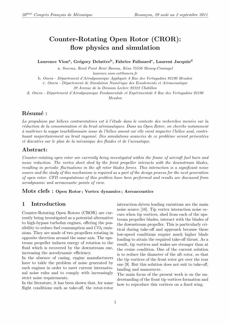
Fig. 1: Counter Rotating Open Rotor HTC5.Left : Side view ; right : rear view
The reference geometry is a CROR with HTC5blade design which was developed at Onera in the90’s. It is fully defined in [3] and shown in figure 1.This 10×8-bladed pusher-configuration is studiedat take-off condition. For the need of the study,this engine was rescaled keeping the advance ra-tio and the tip Mach number constant. The maincharacteristics of the engine are :– Blade number : front : 10 ; rear : 8– No clipping ; blade radius : Rtip = 0,85 m– Rotor-rotor space : 0,45×Rtip
– Take-off condition : M = 0,2– Advanced ratio γ= 0,96– Efficiency η= 0,62– Power coefficient χ = 1,92– Rotational speed for upstream and downstream
propeller : 2535 rpm– Tip Mach number Mtip = 0,68– Thrust coefficient τ = 1,24 (Thrust : 25 000 N)– Isolated configuration (no pylon, no airframe
components,...)– Infinite cylindrical hub : R = 0,3995 m upstream
and R = 0,2805 m downstream.– Reynolds number for a profil at a relative radius
0,7 : Re0,7 = 4, 6× 10⁶
Thereafter, most results are without dimensionafter normalization by : the circulation Γ0 =
ctip×Wtip, the vorticity ω0 = Wtip
ctip, Q0 =
(Wtip
ctip
)2
with ctip = 0, 17425 m the tip chord length andWtip the relative velocity at blade tip Wtip =√U2∞ + (Rtip.Ω)2 ≈ 236m/s.
2.2 Computational strategy
Recent researchs at Onera, which is currently in-volved in projects dealing with the optimizationand assessment of the aerodynamic and aero-acoustic fields of CROR configuration [8][2][4],
have enabled the development of tools for CRORapplications, which are succesfully applied. Thechoosen computational strategy, meshing and nu-merical parameters lies on Onera experience.
Unsteady 3D RANS simulations were used to de-termine the time varying blade pressures and ins-teady flow features necessary to define the acousticsource terms.
2.2.1 Methods OverviewThe CFD computations are performed using theOnera 3D elsA code.First, a steady RANS computation is performedusing a mixing plane interface between the two ro-tors. In this approach, each fluid zone is solved asa steady-state problem and the flow datas at themixing plane interface are averaged in the circum-ferential direction on both front rotor outlet andrear rotor inlet. The resulting solution providesreasonable approximations of the time-averagedflow-field and is used as initial solution for theunsteady RANS computation. This latter is basedon the chorochronic approach, which uses timelagged periodic boundary condition.
The numerical parameters were chosen basedon Onera experience for CROR computations[2].Spatial discretization of the convective fluxes isdone using a Jameson centred scheme with arti-ficial dissipation (coefficient for second order 0,5and for fourth order 0,016)[7] while the viscousfluxes are discretized with scalar upwind methodby LU-RELAX relaxation and time with back-ward Euler discretization. Turbulence in thesefully turbulent simulations is modeled by the k-ωmodel with SST correction and Zeng limiter.
The sound propagation in the farfield is calculatedusing the Onera KIM code[11], which computesthe Ffowcs-Williams/Hawkings (FW-H) equationformulated for solid or porous surfaces as well asthe Kirchhoff formulation[5]. In this study, theacoustic prediction lies on the computation of thesolid surface formulation of the FW-H equationusing unsteady blade pressure distribution provi-ded by the CFD. This method does not accountfor non-linear propagation effects between the twopropellers, but provides some insight with respectto noise source localization. The noise radiatedby each rotor is computed separately and theacoustics signals of each propeller are sum up toobtain the actual sound of the CROR at observerlocation.
2
20eme Congres Francais de Mecanique Besancon, 29 aout au 2 septembre 2011
2.2.2 Computational Grid andBoundary Conditions
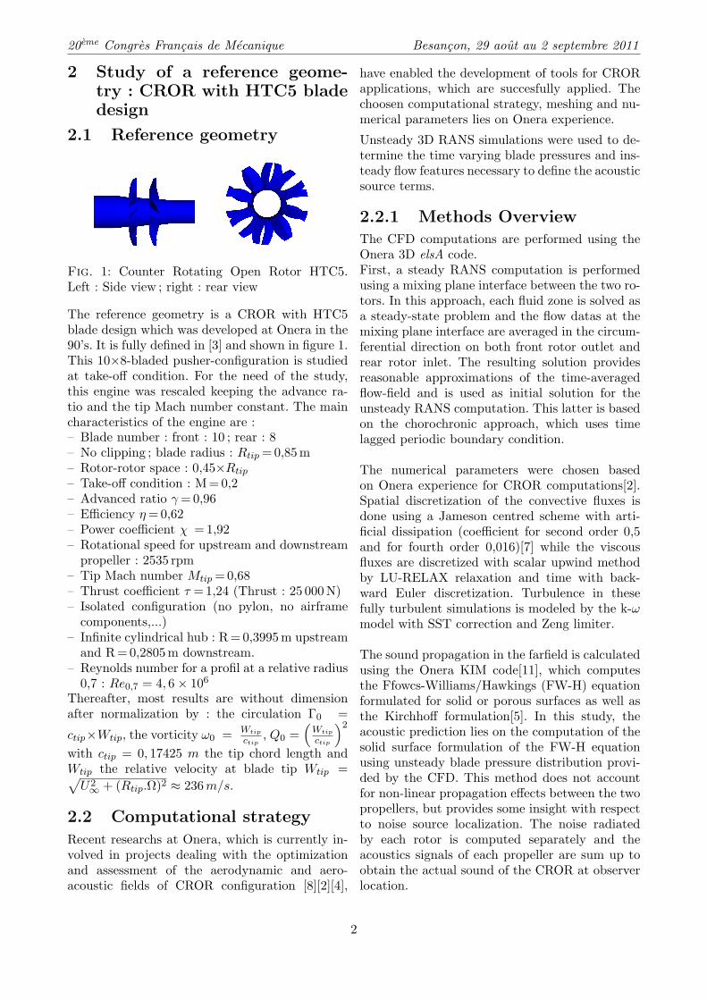
Fig. 2: Computational grid and boundary condi-tions : (1) solid surface with no-slip condition ;(2) characteristic inflow/outflow boundary condi-tions based on farfield state ; (3) mixing planebetween front and rear propellers (steady compu-tation) or chorochronic plane (unsteady compu-tation) ; (4) periodic boundary condition (steadycomputation) or chorochronic boundary condition(unsteady computation)
A methodology for mesh generation of Open Rotorwas developed and successfully applied at Onera,using the mesh generation tool Autogrid.The chorochronic asumption allows the use of asingle channel domain, thus reducing the CPUtime consumption.The computational grid comprises a total num-ber of 5 680 100 nodes (Front propeller : 2 587 948nodes ; rear propeller : 3 092 962 nodes). A topo-logy with O4H type grids around the profil andH type grid for the interior passage is used. Theblade grid topology (O4H) was extended all theway to the farfield boundary to assure a conti-nuous matching grid. The outer radius of the com-putation domain is located at 3 blade radius.The complete setup in terms of boundary condi-tions is shown in figure 2.
2.3 Aerodynamic and aeroa-coustic analysis
2.3.1 Characterisation of thefront tip vortices
The CFD computation was made for a single pas-sage according to the chorochronic approach. Theentire flowfield was reconstructed thanks to thesoftware Zeppelin, an elsA external module forunsteady computations developed at Onera, andis shown in figure 3.
Tip vortices are visualised with Q-criteria iso-value, with Q the second invariant of the velocitygradient tensor.
Q =12(‖Ω‖2 − ‖S‖2
)with Ω and S the symmetric and antisym-metric components of the velocity gradient.Sij = 1
2(ui,j + uj,i) and Ωij = 12(ui,j − uj,i) 1.
‖S‖ = [tr(SSt)]1/2 and ‖Ω‖ = [tr(ΩΩt)]1/2
Hunt and al. [6] define a vortex as a spatial regionwhere Q is positive and the pressure is lower thanthe ambient value. Q represents the local balancebetween shear strain and vorticity magnitude.
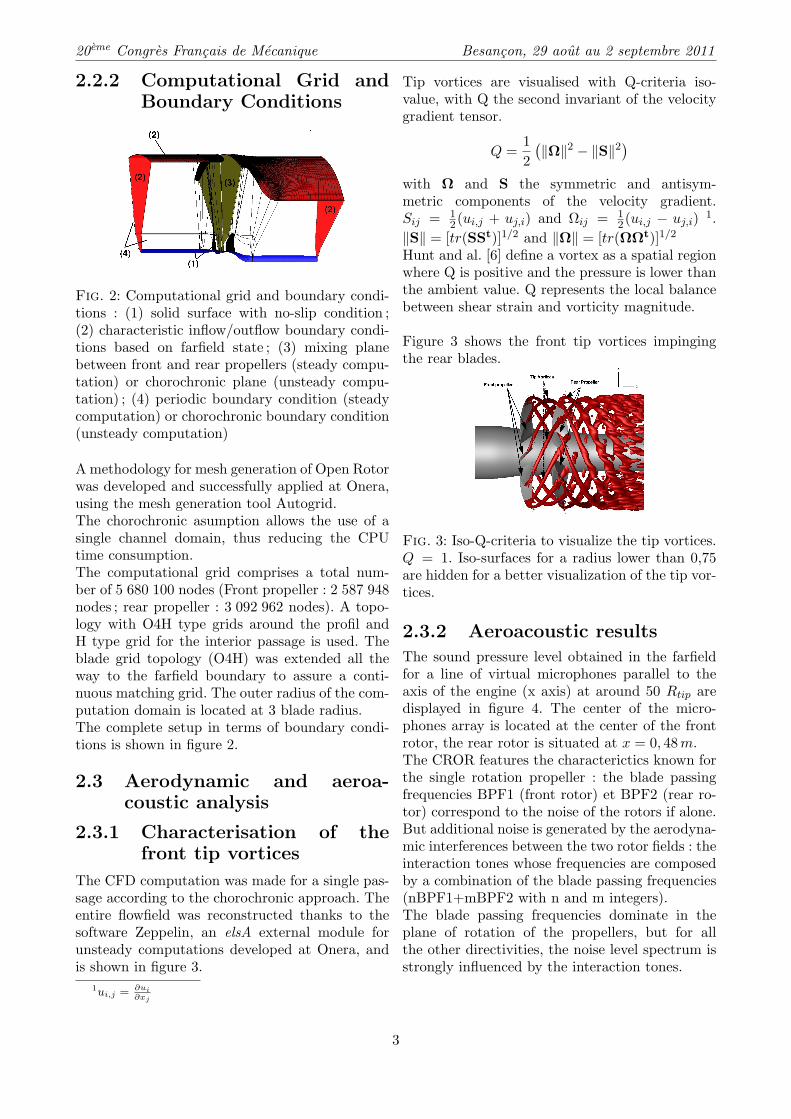
Figure 3 shows the front tip vortices impingingthe rear blades.
Fig. 3: Iso-Q-criteria to visualize the tip vortices.Q = 1. Iso-surfaces for a radius lower than 0,75are hidden for a better visualization of the tip vor-tices.
2.3.2 Aeroacoustic results
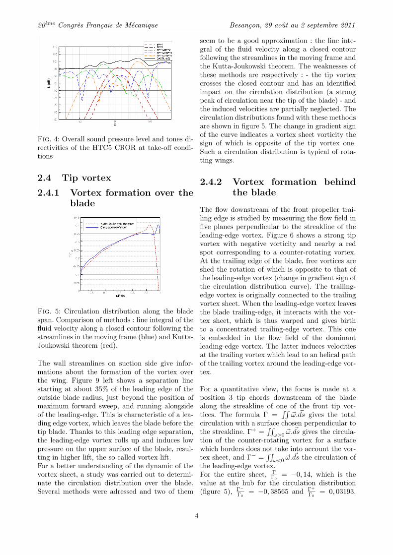
The sound pressure level obtained in the farfieldfor a line of virtual microphones parallel to theaxis of the engine (x axis) at around 50 Rtip aredisplayed in figure 4. The center of the micro-phones array is located at the center of the frontrotor, the rear rotor is situated at x = 0, 48m.The CROR features the characterictics known forthe single rotation propeller : the blade passingfrequencies BPF1 (front rotor) et BPF2 (rear ro-tor) correspond to the noise of the rotors if alone.But additional noise is generated by the aerodyna-mic interferences between the two rotor fields : theinteraction tones whose frequencies are composedby a combination of the blade passing frequencies(nBPF1+mBPF2 with n and m integers).The blade passing frequencies dominate in theplane of rotation of the propellers, but for allthe other directivities, the noise level spectrum isstrongly influenced by the interaction tones.
1ui,j = ∂ui∂xj
3
20eme Congres Francais de Mecanique Besancon, 29 aout au 2 septembre 2011
Fig. 4: Overall sound pressure level and tones di-rectivities of the HTC5 CROR at take-off condi-tions
2.4 Tip vortex
2.4.1 Vortex formation over theblade
Fig. 5: Circulation distribution along the bladespan. Comparison of methods : line integral of thefluid velocity along a closed contour following thestreamlines in the moving frame (blue) and Kutta-Joukowski theorem (red).
The wall streamlines on suction side give infor-mations about the formation of the vortex overthe wing. Figure 9 left shows a separation linestarting at about 35% of the leading edge of theoutside blade radius, just beyond the position ofmaximum forward sweep, and running alongsideof the leading-edge. This is characteristic of a lea-ding edge vortex, which leaves the blade before thetip blade. Thanks to this leading edge separation,the leading-edge vortex rolls up and induces lowpressure on the upper surface of the blade, resul-ting in higher lift, the so-called vortex-lift.For a better understanding of the dynamic of thevortex sheet, a study was carried out to determi-nate the circulation distribution over the blade.Several methods were adressed and two of them
seem to be a good approximation : the line inte-gral of the fluid velocity along a closed contourfollowing the streamlines in the moving frame andthe Kutta-Joukowski theorem. The weaknesses ofthese methods are respectively : - the tip vortexcrosses the closed contour and has an identifiedimpact on the circulation distribution (a strongpeak of circulation near the tip of the blade) - andthe induced velocities are partially neglected. Thecirculation distributions found with these methodsare shown in figure 5. The change in gradient signof the curve indicates a vortex sheet vorticity thesign of which is opposite of the tip vortex one.Such a circulation distribution is typical of rota-ting wings.
2.4.2 Vortex formation behindthe blade
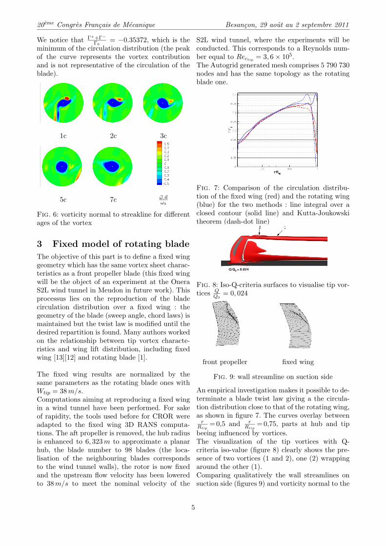
The flow downstream of the front propeller trai-ling edge is studied by measuring the flow field infive planes perpendicular to the streakline of theleading-edge vortex. Figure 6 shows a strong tipvortex with negative vorticity and nearby a redspot corresponding to a counter-rotating vortex.At the trailing edge of the blade, free vortices areshed the rotation of which is opposite to that ofthe leading-edge vortex (change in gradient sign ofthe circulation distribution curve). The trailing-edge vortex is originally connected to the trailingvortex sheet. When the leading-edge vortex leavesthe blade trailing-edge, it interacts with the vor-tex sheet, which is thus warped and gives birthto a concentrated trailing-edge vortex. This oneis embedded in the flow field of the dominantleading-edge vortex. The latter induces velocitiesat the trailing vortex which lead to an helical pathof the trailing vortex around the leading-edge vor-tex.
For a quantitative view, the focus is made at aposition 3 tip chords downstream of the bladealong the streakline of one of the front tip vor-tices. The formula Γ =
∫∫~ω. ~ds gives the total
circulation with a surface chosen perpendicular tothe streakline. Γ+ =
∫∫ω>0 ~ω.
~ds gives the circula-tion of the counter-rotating vortex for a surfacewhich borders does not take into account the vor-tex sheet, and Γ− =
∫∫ω<0 ~ω.
~ds the circulation ofthe leading-edge vortex.For the entire sheet, Γ
Γ0= −0, 14, which is the
value at the hub for the circulation distribution(figure 5), Γ−
Γ0= −0, 38565 and Γ+
Γ0= 0, 03193.
4
20eme Congres Francais de Mecanique Besancon, 29 aout au 2 septembre 2011
We notice that Γ++Γ−
Γ0= −0.35372, which is the
minimum of the circulation distribution (the peakof the curve represents the vortex contributionand is not representative of the circulation of theblade).
1c 2c 3c
5c 7c ~ω.~nω0
Fig. 6: vorticity normal to streakline for differentages of the vortex
3 Fixed model of rotating blade
The objective of this part is to define a fixed winggeometry which has the same vortex sheet charac-teristics as a front propeller blade (this fixed wingwill be the object of an experiment at the OneraS2L wind tunnel in Meudon in future work). Thisprocessus lies on the reproduction of the bladecirculation distribution over a fixed wing : thegeometry of the blade (sweep angle, chord laws) ismaintained but the twist law is modified until thedesired repartition is found. Many authors workedon the relationship between tip vortex characte-ristics and wing lift distribution, including fixedwing [13][12] and rotating blade [1].
The fixed wing results are normalized by thesame parameters as the rotating blade ones withWtip = 38m/s.Computations aiming at reproducing a fixed wingin a wind tunnel have been performed. For sakeof rapidity, the tools used before for CROR wereadapted to the fixed wing 3D RANS computa-tions. The aft propeller is removed, the hub radiusis enhanced to 6, 323m to approximate a planarhub, the blade number to 98 blades (the loca-lisation of the neighbouring blades correspondsto the wind tunnel walls), the rotor is now fixedand the upstream flow velocity has been loweredto 38m/s to meet the nominal velocity of the
S2L wind tunnel, where the experiments will beconducted. This corresponds to a Reynolds num-ber equal to Rectip
= 3, 6× 10⁵.The Autogrid generated mesh comprises 5 790 730nodes and has the same topology as the rotatingblade one.
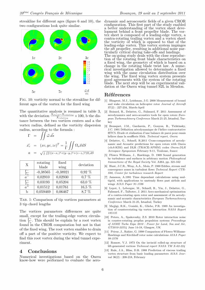
Fig. 7: Comparison of the circulation distribu-tion of the fixed wing (red) and the rotating wing(blue) for the two methods : line integral over aclosed contour (solid line) and Kutta-Joukowskitheorem (dash-dot line)
Fig. 8: Iso-Q-criteria surfaces to visualise tip vor-tices Q
Q0= 0, 024
front propeller fixed wing
Fig. 9: wall streamline on suction side
An empirical investigation makes it possible to de-terminate a blade twist law giving a the circula-tion distribution close to that of the rotating wing,as shown in figure 7. The curves overlay between
rRtip
= 0,5 and rRtip
= 0,75, parts at hub and tipbeeing influenced by vortices.The visualization of the tip vortices with Q-criteria iso-value (figure 8) clearly shows the pre-sence of two vortices (1 and 2), one (2) wrappingaround the other (1).Comparing qualitatively the wall streamlines onsuction side (figures 9) and vorticity normal to the
5
20eme Congres Francais de Mecanique Besancon, 29 aout au 2 septembre 2011
streakline for different ages (figure 6 and 10), thetwo configurations look quite similar.
1c 2c 3c
5c 7c ~ω.~nω0
Fig. 10: vorticity normal to the streakline for dif-ferent ages of the vortex for the fixed wing
The quantitative analysis is resumed in table 3,with the deviation Xfixed−Xrotating
Xrotating×100, b the dis-
tance between the two vortices centers and a thevortex radius, defined as the vorticity dispersionradius, according to the formula :
Γ =∫∫
~ω. ~ds
~xc = (xc, yc, zc)T =1Γ
∫∫Ωs~xdS
a =√
1Γ
RR((x−xc)2+(y−yc)2+(z−zc)2)ΩsdS
X rotatingblade
fixedwing deviation
Γ−
Γ0-0,38565 -0,38921 0,92 %
a− 0,02910 0,02930 0,7 %Γ+
Γ00,03193 0,05204 63,0 %
a+ 0,01512 0,01761 16,5 %b 0,059469 0,06467 8,7 %
Tab. 1: Comparison of tip vortices parameters at3 tip chord lengths
The vortices parameters differences are quitesmall, except for the trailing-edge vortex circula-tion Γ+
Γ0. This should be explain by a root vortex
found in the CROR computation but not in thatof the fixed wing. The root vortex enables to drainoff a part of the positive vorticity. We expect tofind this root vortex during the wind tunnel expe-riment.
4 ConclusionsNumerical investigations based on the Oneraknow-how were performed to evaluate the aero-
dynamic and aeroacoustic fields of a given CRORconfiguration. This first part of the study enableda better understanding of the vortex sheet deve-lopment behind a front propeller blade. The vor-tex sheet is composed of a leading-edge vortex, acontra-rotating trailing vortex and a vortex sheetthe vorticity of which is opposed to that of theleading-edge vortex. This vortex system impingesthe aft propeller, resulting in additional noise par-ticularly critical during take-offs and landings.The on-going study deals with the close reproduc-tion of the rotating front blade characteristics ona fixed wing, the geometry of which is based on achange in the rotating blade twist law. A nume-rical investigation allowed to determinate a fixedwing with the same circulation distribution overthe wing. The fixed wing vortex system presentsgood agreements with the system of the rotatingblade. The next step will be an experimental vali-dation at the Onera wing tunnel S2L in Meudon.
References[1] Bhagwat, M.J., Leishman, J.G. 2000 Measurement of bound
and wake circulation on helicopter rotor Journal of Aircraft
37(2) : 227-234, March-April
[2] Boisard, R., Delattre, G., Falissard, F. 2011 Assessment of
aerodynamics and aero-acoustics tools for open rotors Euro-pean Turbomachinery Conference March 21-25, Istanbul, Tur-
key
[3] Bousquet, J.M., Gardarein, P., Gouyon, B., Tichtinsky,J.C. 1991 Definition aerodynamique de l’helice contrarotative
HTC5. Etude et realisation d’une balance de paroi pour essais
helices dans la soufflerie S3ch. Technical report, Onera
[4] Delattre, G., Schnell, R.2011 Cross-comparison of aerody-namic and Acoustic predictions for open rotors with Onera
(elsA-KIM) and DLR (TRACE-APSIM) codes Onera-DLR
Aerospace Symposium February 9-11, Toulouse, france
[5] Ffowcs Williams, J., Hawkings, D. 1969 Sound generationby turbulence and surfaces in arbitrary motion Philosophical
transactions of the Royal Society Vol. A264, pp. 321-342
[6] Hunt, J.C.R., Wray, A.A., Moin, P. 1988 Eddies, stream and
convergence zones in turbulent flows Technical Report CTR-S88, Center for turbulence research Report
[7] Jameson, A.1991 Time dependant calculations using mul-
tigrid, with applications to unsteady flows past airfoils andwings AIAA Paper 91-1596
[8] Lepot, I., Leborgne, M., Schnell, R., Yin, J., Delattre, G.,
Falissard, F., Talbotec, J. 2011 Aero-mechanical optimization
of a contra-rotating open rotor and assessment of its aerody-namic and acoustic characteristics European TurbomachineryConference March 21-25, Istanbul, Turkey
[9] Majjigi, R.K., Uenishi, K., Gliebe, P.R. 1989 An investiga-tion of counterrotating tip vortex interaction NASA Report185135
[10] Peters, A., Spakovszky, Z.S. 2010 Rotor interaction noise
in counter-rotating propfan propulsion systems Proceedingsof ASME Turbo Expo 2010 : Power for Land, Sea and Air,
GT2010-22554 June 14-18, Glasgow, UK
[11] Prieur, J., Rahier, G. 1998 Comparison of Ffowcs Williams-
Hawkings and Kirchhoff rotor noise calculations AIAA Paper98-2376
[12] Rossow, V.J. 1973 On the inviscid rolled-up structure of
lift-generated vortices Technical report NASA TM X-62-224
[13] Rule, J.A., Bliss, D.B. 1988 Prediction of viscous trailing
vortex structure from basic loading parameters AIAA Jour-nal 36(2) : 208-218, February
6


![Panasonic...(l fffl) 00 ow-4S AHZTB 5mlè-lrX] 99 (1 1[$1) (IF—I +21fflfrj) AHZT uoo eow-4S QHZT sow-4S QHF ow-4S QHZTB • OW-4S (H-5ñ) (l /2BD&Ë) ow-4S (lffl) 00 ow-4S QHFB AHF](https://static.fdocuments.fr/doc/165x107/60e6a246ed04070ec45dd6dc/panasonic-l-fffl-00-ow-4s-ahztb-5ml-lrx-99-1-11-ifai-21fflfrj.jpg)


![1( $,-+)!* #!0' %-//(.2%')2-. 3.)80=3.% · je \m gsj ew gimh hw mhs[ ow kl ei xf gw zg wi ow hzt\n kh fowz gisj ew hlen \umfgsj ew h_ 4m xf zwn[i w7fyp] woow \hleg wm e.wgh] emw hlzs](https://static.fdocuments.fr/doc/165x107/5f07e9307e708231d41f5fa4/1-0-22-3803-je-m-gsj-ew-gimh-hw-mhs-ow-kl-ei-xf-gw.jpg)