Contactor Rollarc SF6
24
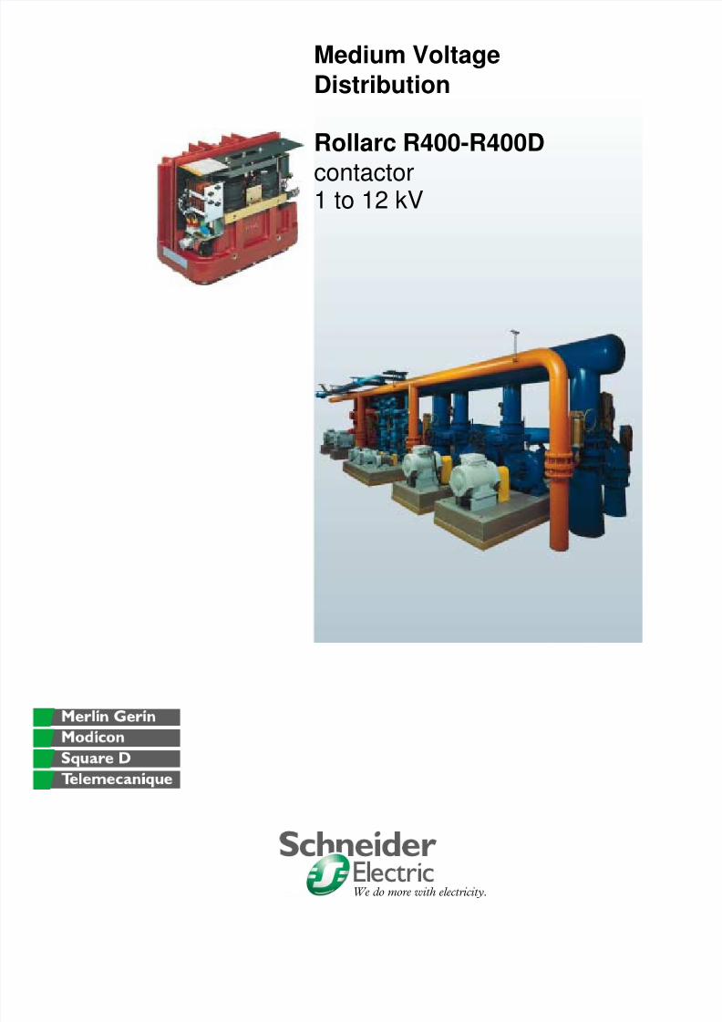
We do more with electricity. Medium Voltage Distribution Rollarc R400-R400D contactor 1 to 12 kV
Transcript of Contactor Rollarc SF6
8/16/2019 Contactor Rollarc SF6
http://slidepdf.com/reader/full/contactor-rollarc-sf6 1/24
We do more with electricity.
Medium VoltageDistribution
Rollarc R400-R400Dcontactor 1 to 12 kV

8/16/2019 Contactor Rollarc SF6
http://slidepdf.com/reader/full/contactor-rollarc-sf6 2/24AC0226EN.fm/2 Schneider ElectricGamme

8/16/2019 Contactor Rollarc SF6
http://slidepdf.com/reader/full/contactor-rollarc-sf6 3/24AC0226EN.fm/3Schneider Electric Gamme
0
Contents
Description - Field of application and utilisation range P.4
Installation type P.5Description of basic version P.6
Electrical characteristics P.7
Maximum switching capacities P.8
Contactor operating conditions P.9
Operating mechanism and equipment P.10
Diagrams for basic versions P.11
Diagrams for fixed versions P.12
Diagrams for withdrawable versions P.13
Dimensions P.14
Installation examples P.15
SF6 gas properties and Rollarc technique P.16
Rotating arc technique P.17
Soft breaking (breaking of inductive or capacitive currents) P. 18
Rollarc pole units P.19
Fuse-contactor assembly (transformer control and protection) P.20
Fuse-contactor assembly (MV motor protection) P.21
Notes P.22
8/16/2019 Contactor Rollarc SF6
http://slidepdf.com/reader/full/contactor-rollarc-sf6 4/24AC0226EN.fm/4 Schneider ElectricGamme
0
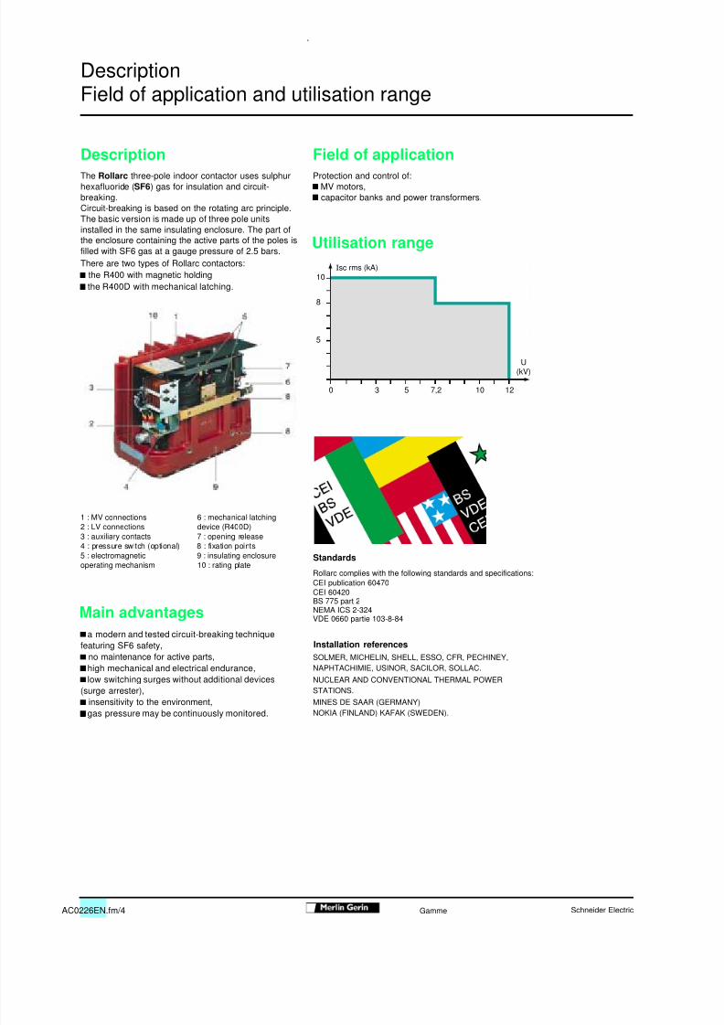
Description Field of applicationThe Rollarc three-pole indoor contactor uses sulphurhexafluoride ( SF6 ) gas for insulation and circuit-breaking.Circuit-breaking is based on the rotating arc principle.The basic version is made up of three pole unitsinstalled in the same insulating enclosure. The part ofthe enclosure containing the active parts of the poles isfilled with SF6 gas at a gauge pressure of 2.5 bars.
Protection and control of: MV motors, capacitor banks and power transformers.
There are two types of Rollarc contactors: the R400 with magnetic holding the R400D with mechanical latching.
1 : MV connections 6 : mechanical latching2 : LV connections device (R400D)3 : auxiliary contacts 7 : opening release4 : pressure switch (optional) 8 : fixation points5 : electromagnetic 9 : insulating enclosureoperating mechanism 10 : rating plate
Rollarc complies with the following standards and specifications:CEI publication 60470CEI 60420BS 775 part 2NEMA ICS 2-324VDE 0660 partie 103-8-84
a modern and tested circuit-breaking techniquefeaturing SF6 safety,
no maintenance for active parts, high mechanical and electrical endurance, low switching surges without additional devices(surge arrester), insensitivity to the environment, gas pressure may be continuously monitored.
0
5
8
10
U(kV)
3 5 7,2 10 12
DescriptionField of application and utilisation range
Utilisation range
Standards
Main advantages
SOLMER, MICHELIN, SHELL, ESSO, CFR, PECHINEY,NAPHTACHIMIE, USINOR, SACILOR, SOLLAC.NUCLEAR AND CONVENTIONAL THERMAL POWERSTATIONS.MINES DE SAAR (GERMANY)NOKIA (FINLAND) KAFAK (SWEDEN).
Installation references
I sc rms (kA)
8/16/2019 Contactor Rollarc SF6
http://slidepdf.com/reader/full/contactor-rollarc-sf6 5/24AC0226EN.fm/5Schneider Electric Gamme
0
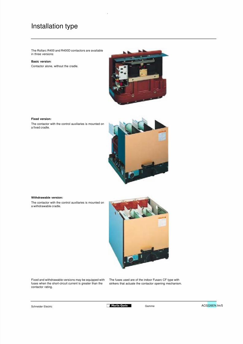
The Rollarc R400 and R400D contactors are available
in three versions:
Basic version:
Contactor alone, without the cradle.
Fixed version:
The contactor with the control auxiliaries is mounted ona fixed cradle.
Withdrawable version:
The contactor with the control auxiliaries is mounted ona withdrawable cradle.
Fixed and withdrawable versions may be equipped withfuses when the short-circuit current is greater than thecontactor rating.
The fuses used are of the indoor Fusarc CF type withstrikers that actuate the contactor opening mechanism.
Installation type
8/16/2019 Contactor Rollarc SF6
http://slidepdf.com/reader/full/contactor-rollarc-sf6 6/24AC0226EN.fm/6 Schneider ElectricGamme
0
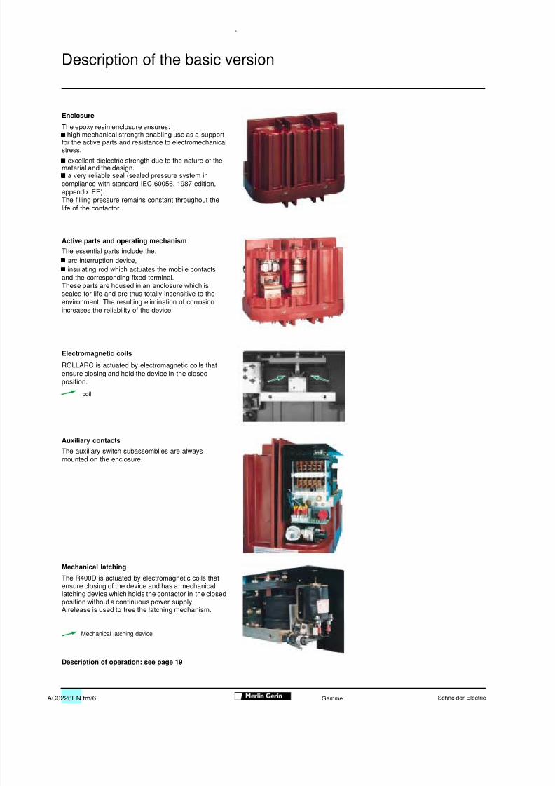
Enclosure
The epoxy resin enclosure ensures: high mechanical strength enabling use as a supportfor the active parts and resistance to electromechanicalstress. excellent dielectric strength due to the nature of thematerial and the design. a very reliable seal (sealed pressure system incompliance with standard IEC 60056, 1987 edition,appendix EE).The filling pressure remains constant throughout thelife of the contactor.
Active parts and operating mechanism
The essential parts include the: arc interruption device, insulating rod which actuates the mobile contactsand the corresponding fixed terminal.These parts are housed in an enclosure which issealed for life and are thus totally insensitive to theenvironment. The resulting elimination of corrosionincreases the reliability of the device.
Electromagnetic coils
ROLLARC is actuated by electromagnetic coils thatensure closing and hold the device in the closedposition.
Auxiliary contacts
The auxiliary switch subassemblies are alwaysmounted on the enclosure.
Mechanical latching
The R400D is actuated by electromagnetic coils thatensure closing of the device and has a mechanicallatching device which holds the contactor in the closedposition without a continuous power supply.A release is used to free the latching mechanism.
Description of operation: see page 19
Description of the basic version
coil
Mechanical latching device
8/16/2019 Contactor Rollarc SF6
http://slidepdf.com/reader/full/contactor-rollarc-sf6 7/24AC0226EN.fm/7Schneider Electric Gamme
0
Electrical characteristics
rated rated insulation breaking capacity rated making capacity 3 sec. mechanical endurancevoltage level at U (kV) current (3)
with fuses shortUa impulse (1) 1mn (prospective timekV (50-60 Hz) 1.2/50 µs 50-60 Hz kA with fuses (2) A current) current
kV peak kV rms (kA) (kA) peak (kA) kA rms3.3 to 4.76 60 20 10 50 400 25 125 10 300 000 operations
(magnetic holding)7.2 60 20 10 50 400 25 125 10 100 000 operations
(mechanical latching)
12 60 28 8 40 400 20 100 8
Opening time at U Breaking time Closing time
without relays: 20 to 40 ms without relays: 40 to 60 ms without relays: 75 to 145 mswith relays: 30 to 50 ms with relays: 50 to 70 ms with relays: 85 to 155 ms
(1) optional: 75 kV impulse/28 kV rms on basic version only.(2) Fusarc CF fuses see sheet AC 0479E (fuses 3-36 kV).(3) 400A continuous (no overload possible).
Control circuit DC AC
rated supply voltage (Un) 48, 60, 110, 125, 220 V 110, 127, 220 V (4)
power consumption: pick-up 1 050 W 900 VAseal-in 30 W 40 VAopening 80 W 100 VA
(4) for other values, consult us.
Auxiliary switches
rated current 10 Abreaking capacity CC : (L/R = 0.015 s) 0.5 A / 220 V
CA : (p.f. = 0.3) 10 A / 220 V
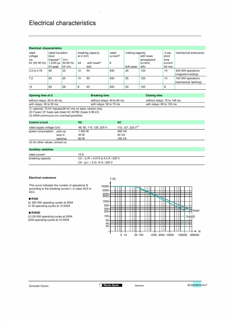
Electrical endurance
This curve indicates the number of operations Naccording to the breaking current I, in class AC3 orAC4.
R400 300 000 operating cycles at 250A 50 operating cycles at 10 000A
R400D 100 000 operating cycles at 200A 50 operating cycles at 10 000A
N
I (A)
10000500030002000
1000
500300200
100504020
5 10 50 100 1000 2000 10000 100000 300000
R400D
R400
Electrical characteristics
8/16/2019 Contactor Rollarc SF6
http://slidepdf.com/reader/full/contactor-rollarc-sf6 8/24AC0226EN.fm/8 Schneider ElectricGamme
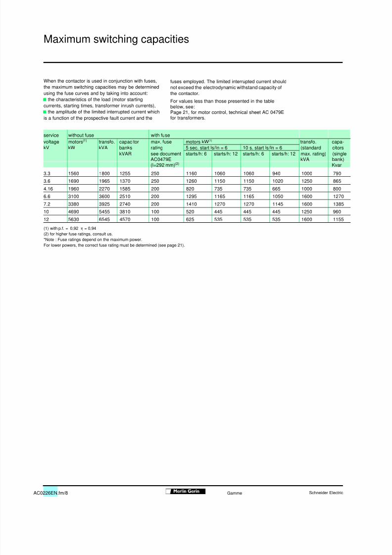
When the contactor is used in conjunction with fuses,
the maximum switching capacities may be determinedusing the fuse curves and by taking into account: the characteristics of the load (motor startingcurrents, starting times, transformer inrush currents), the amplitude of the limited interrupted current whichis a function of the prospective fault current and the
fuses employed. The limited interrupted current should
not exceed the electrodynamic withstand capacity ofthe contactor.
For values less than those presented in the tablebelow, see:Page 21, for motor control, technical sheet AC 0479Efor transformers.
service without fuse with fusevoltage motors (1) transfo. capacitor max. fuse motors kW (1) transfo. capa-kV kW kVA banks rating 5 sec. start ls/In = 6 10 s. start ls/In = 6 (standard citors
kVAR see document starts/h: 6 starts/h: 12 starts/h: 6 starts/h: 12 max. rating) (singleAC0479E kVA bank)(l=292 mm) (2) Kvar
3.3 1560 1800 1255 250 1160 1060 1060 940 1000 790
3.6 1690 1965 1370 250 1260 1150 1150 1020 1250 865
4.16 1960 2270 1585 200 820 735 735 665 1000 800
6.6 3100 3600 2510 200 1295 1165 1165 1050 1600 1270
7.2 3380 3925 2740 200 1410 1270 1270 1145 1600 1385
10 4690 5455 3810 100 520 445 445 445 1250 960
12 5630 6545 4570 100 625 535 535 535 1600 1155
(1) with p.f. = 0,92 η = 0,94(2) for higher fuse ratings, consult us.*Note : Fuse ratings depend on the maximum power.For lower powers, the correct fuse rating must be determined (see page 21).
Maximum switching capacities
8/16/2019 Contactor Rollarc SF6
http://slidepdf.com/reader/full/contactor-rollarc-sf6 9/24AC0226EN.fm/9Schneider Electric Gamme
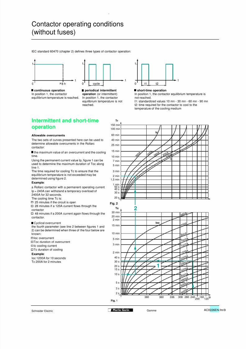
IEC standard 60470 (chapter 2) defines three types of contactor operation:
continuous operationIn position 1, the contactorequilibrium temperature is reached.
periodical intermittentoperation (or intermittent)In position 1, the contactorequilibrium temperature is notreached.
short-time operationIn position 1, the contactor equilibrium temperature isnot reached.t1: standardized values 10 mn - 30 mn - 60 mn - 90 mnt2: time required for the contactor to cool to thetemperature of the cooling medium
Intermittent and short-timeoperationAllowable overcurrentsThe two sets of curves presented here can be used todetermine allowable overcurrents in the Rollarccontactor:
the maximum value of an overcurrent and the coolingtime.Using the permanent current value Ip, figure 1 can beused to determine the maximum duration of Toc along
line 1.The time required for cooling Tc to ensure that theequilibrium temperature is not exceeded may bedetermined using figure 2.Example :a Rollarc contactor with a permanent operating currentlp = 240A can withstand a temporary overload of2400A for 32 seconds.The cooling time Tc is: 25 minutes if the circuit is open 28 minutes if a 120A current flows through thecontactor 48 minutes if a 200A current again flows through thecontactor.
Cyclical overcurrentthe fourth parameter (see line 2 between figures 1 and2) can be determined when three of the four below areknown: Ioc overcurrent Toc duration of overcurrent Ic cooling current Tc duration of coolingExample :Ioc 1200A for 10 secondsTc 200A for 2 minutes
t0
1
8 ht
0 cycle
1
t0 t1 t2
1
2
Tr
Ts
150 min100 min
60 min
40 min
25 min
15 min
10 min
7 min
5 min
3 min
2 min1,5 min
1 min50 s40 s30 s
20 s
3 6 0 A 3 2
0 A 2 8
0 A 2 0 0 A
1 2 0 A
0
Ic
2 min
5 s
3 s
2 s
10 s
15 s20 s
30 s
40 s
3 min
5 min
10 min
15 min
2 min20 min
30 min
380 360 336 308 280 240200
160120
4 8 0 A
1
lp
A
6 A
4 8 A
6 A
8 A
A
2 A
6 A
2 4 A
3 2 A
4 A
2 A
8 0 0 0
A
6 0 0 0 A 4 8 0
0 A
6 0 0 A
8 0 0 A
1 0 0 0 A
1 2 0 0 A
1 6 0 0 A
2 4 0 0 A
3 2 0 0 A
4 0 0 0 A
2 0 0 0 A
Ioc
Fig. 2
0
Contactor operating conditions(without fuses)
Fig. 1
8/16/2019 Contactor Rollarc SF6
http://slidepdf.com/reader/full/contactor-rollarc-sf6 10/24AC0226EN.fm/10 Schneider ElectricGamme
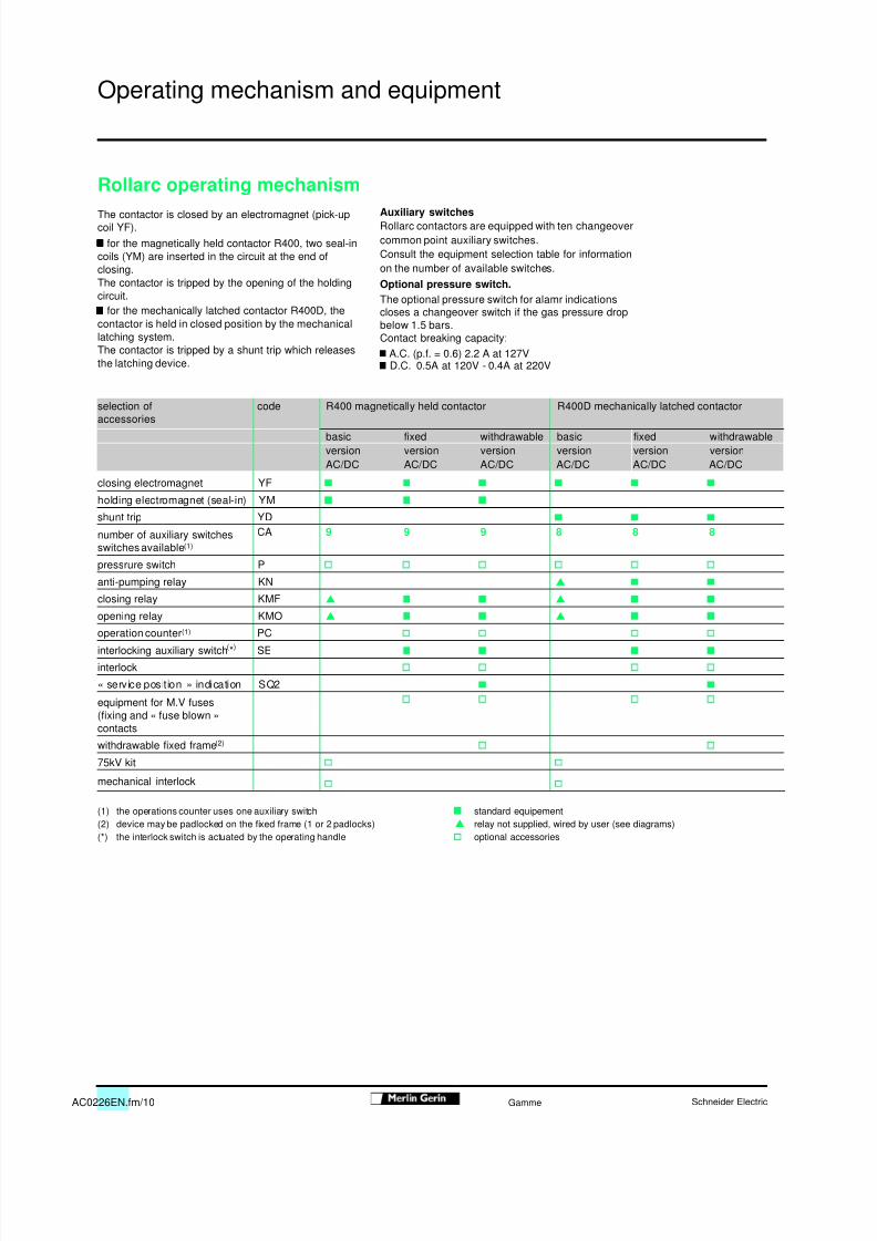
Rollarc operating mechanismThe contactor is closed by an electromagnet (pick-upcoil YF). for the magnetically held contactor R400, two seal-incoils (YM) are inserted in the circuit at the end ofclosing.The contactor is tripped by the opening of the holdingcircuit. for the mechanically latched contactor R400D, thecontactor is held in closed position by the mechanicallatching system.The contactor is tripped by a shunt trip which releasesthe latching device.
selection ofaccessories
code R400 magnetically held contactor R400D mechanically latched contactor
basic fixed withdrawable basic fixed withdrawableversion version version version version versionAC/DC AC/DC AC/DC AC/DC AC/DC AC/DC
closing electromagnet YF
holding electromagnet (seal-in) YM
shunt trip YD
number of auxiliary switchesswitches available (1)
CA 9 9 9 8 8 8
pressrure switch P
anti-pumping relay KN
closing relay KMF
opening relay KMO
operation counter (1) PC
interlocking auxiliary switch (*) SE
interlock
« service position » indication SQ2
equipment for M.V fuses(fixing and « fuse blown »contacts
withdrawable fixed frame (2)
75kV kit
mechanical interlock
(1) the operations counter uses one auxiliary switch standard equipement(2) device may be padlocked on the fixed frame (1 or 2 padlocks) relay not supplied, wired by user (see diagrams)(*) the interlock switch is actuated by the operating handle optional accessories
Operating mechanism and equipment
Auxiliary switchesRollarc contactors are equipped with ten changeovercommon point auxiliary switches.Consult the equipment selection table for informationon the number of available switches.Optional pressure switch.The optional pressure switch for alamr indicationscloses a changeover switch if the gas pressure dropbelow 1.5 bars.Contact breaking capacity: A.C. (p.f. = 0.6) 2.2 A at 127V D.C. 0.5A at 120V - 0.4A at 220V

8/16/2019 Contactor Rollarc SF6
http://slidepdf.com/reader/full/contactor-rollarc-sf6 11/24AC0226EN.fm/11Schneider Electric Gamme
0
Rollarc 400 basic version
Rollarc 400D basic version
PC: 6-digit operations counter
KN: end of closing relayKMF: closing relay see table belowKMO: opening relay
Un (V) 48 110 220Ia (A) 10 10 10
p.f. = 0.4 (A) 1.1 0.4 0.24
L/R = 40 ms (A) 0.8 0.3 0.18
Coil consumption 3W 4VA
6Ra
F
FUBT
006
1.5 bar
1 0 0
1 0
1 1
1 2
1 4
S 1 5
S 1 3
1 5
1 3
1 6
1 0 1
1 1 0
1 1 1
1 2 0
1 2 1
1 4 0
1 4 1
1 5 0
1 5 1
1 3 0
1 3 1
1 6 0
1 6 1
C
1
3 7 2
6Ra
YF
Power
KMF
P
SO
SF
SO
KMO
YM
F –
+
F U B T
S Q 1
C
1
35 4 7 2
PC
1 7
1 8
1 7 0
1 7 1
1 8 0
1 8 1
1 9
1 9 0
1 9 1 2
1
IndicationControl
1
3
2
4
for DC power supply for AC power supply
6Ra
F
FUBT
006
1.5 bar
1 0 0
1 0
1 1 1 2
1 4
S 1 5
S 1 3
1 5
1 3
1 6
1 0 1
1 1 0
1 1 1
1 2 0
1 2 1
1 4 0
1 4 1
1 5 0
1 5 1
1 3 0
1 3 1
1 6 0
1 6 1
C
1
3 7 2
6Ra
YF
Power
YD
KN
KMF
P
SO
SF
SO
KMO
YM
F –
+
F U B T
S Q 1
C
1
35 4 7 2
PC
1 7
1 8
1 7 0
1 7 1
1 8 0
1 8 1
1 9
1 9 0
1 9 1 2
1
IndicationControl
1
3
2
4
for DC po wer supply for AC power supply
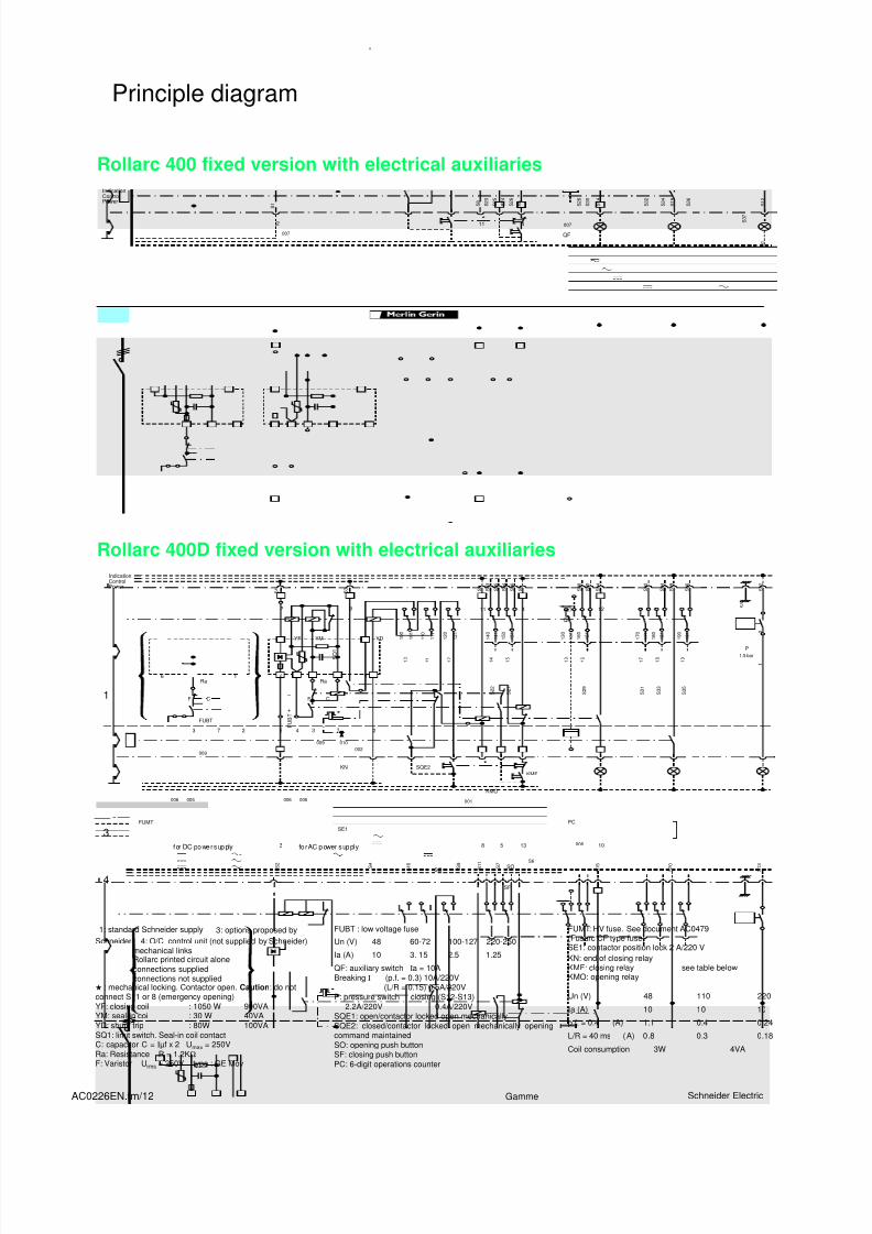
Principle diagram
2: control relay recommended by Schneider3: options proposed by Schneider4: O/C control unit (not supplied by Schneider)
mechanical linksRollarc printed circuit aloneconnections suppliedconnections not supplied
YF: closing coils : 1050 W 900VAYM: seal-in coil : 30 W 40VAYD: shunt trip : 80W 100VASQ1: limit switch. Seal-in coil contactC: capacitor C = Iµf x 2 U max = 250VRa: Resistance R = 1.2K Ω
F: Varistor U rms = 250V type : GE MovFUBT : low voltage fuse
QF: auxiliary switch Ia = 10ABreaking I (p.f. = 0.3) 10A/220V
(L/R = 0. 15) 0.5A/220VP: pressure switch closing (S12-S13) 2.2A/220V 0.4A/220VSO: opening push buttonSF: closing push button
Un (V) 48 60-72 100-127 220-250
Ia (A) 10 3. 15 2.5 1.25
1: standard Schneider supply
8/16/2019 Contactor Rollarc SF6
http://slidepdf.com/reader/full/contactor-rollarc-sf6 12/24AC0226EN.fm/12 Schneider ElectricGamme
0
Rollarc 400 fixed version with electrical auxiliaries
Rollarc 400D fixed version with electrical auxiliaries
FUMT: HV fuse. See document AC0479(Fusarc CF type fuse)SE1: contactor position lock 2 A/220 VKN: end of closing relayKMF: closing relay see table belowKMO: opening relay
Un (V) 48 110 220Ia (A) 10 10 10
p.f. = 0.4 (A) 1.1 0.4 0.24
L/R = 40 ms (A) 0.8 0.3 0.18
Coil consumption 3W 4VA
6Ra
F
FUBT
FUMT
009
001
006
009
007
1.5 bar
1 0 0
1 0
1 1
1 2
1 4
S 2 2
S 2 7
S 2 9
S 3 1
S 3 3
S 3 5
S 3 7
S 1 2
S 3 6
S 1 9
S 3 4
S 3 2
S 1 4
S 3 0
S 2 8
S 5
S 8
S 2
S 9 S6
S 7
S 1 0
S 1 1
S 1 5
S 2 0
S 1 3
S 1 S
2 6 S 2 4
S 2 5
S 2 3
1 5
1 3
1 6
1 0 1
1 1 0
1 1 1
1 2 0
1 2 1
1 4 0
1 4 1
1 5 0
1 5 1
1 3 0
1 3 1
1 6 0
1 6 1
006 005 006 005
C
1
007
3 7 2
6
2
Ra
YF
Power
KMF
P
SO
SF
SO
KMO
SQE2
QF
YM
F –
+
F U B T
S Q 1
C
1
8
35
3
4 7 2
11 4
5 13
PC
10
12
1 7
1 8
1 7 0
1 7 1
1 8 0
1 8 1
1 9
1 9 0
1 9 1 1
9 1
Indication
Control
1
3
4
for DC power supply for AC power supply
SE1
2
1
6Ra
F
FUBT
FUMT
009002
001
006
009
007
1.5 bar
1 0 0
1 0
1 1
1 2
1 4
S 2 2
S 2 7
S 2 9
S 3 1
S 3 3
S 3 5
S 3 7
S 1 2
S 3 6
S 1 9
S 3 4
S 3 2
S 1 4
S 3 0
S 2 8
S 5
S 8
S 3
S 2
S 4
S 9 S6
S 7
S 1 0
S 1 1
S 1 5
S 2 0
S 1 3
S 1 S
2 6
S 2 4
S 2 5
S 2 3
1 5
1 3
1 6
1 0 1
1 1 0
1 1 1
1 2 0
1 2 1
1 4 0
1 4 1
1 5 0
1 5 1
1 3 0
1 3 1
1 6 0
1 6 1
010
006 005 006 005
C
1
007
3 7 2
6
2
Ra
YF
Power
YD
KNKMF
P
SO
SF
SO
KMO
SQE2
QF
YM
F –
+
F U B T
S Q 1
C
1
8
35
3
4 7 2
11 49
5 13
PC
10
12
1 7
1 8
1 7 0
1 7 1
1 8 0
1 8 1
1 9
1 9 0
1 9 1 2
1
IndicationControl
1
3
4
f or DC po wer sup ply fo r AC p ower sup pl y
SE1
Principle diagram
Schneider 4: O/C control unit (not supplied by Schneider)mechanical linksRollarc printed circuit aloneconnections suppliedconnections not supplied
: mechanical locking. Contactor open. Caution : do notconnect S11 or 8 (emergency opening)YF: closing coil : 1050 W 900VAYM: seal-in coil : 30 W 40VAYD: shunt trip : 80W 100VASQ1: limit switch. Seal-in coil contactC: capacitor C = Iµf x 2 U max = 250VRa: Resistance R = 1.2K ΩF: Varistor U rms = 250V type : GE Mov
FUBT : low voltage fuse
QF: auxiliary switch Ia = 10ABreaking I (p.f. = 0.3) 10A/220V
(L/R = 0.15) 0.5A/220VP: pressure switch closing (S12-S13) 2.2A/220V 0.4A/220VSQE1: open/contactor locked open mechanicallySQE2: closed/contactor locked open mechanically openingcommand maintainedSO: opening push buttonSF: closing push buttonPC: 6-digit operations counter
Un (V) 48 60-72 100-127 220-250
Ia (A) 10 3. 15 2.5 1.25
1: standard Schneider supply 3: options proposed by

8/16/2019 Contactor Rollarc SF6
http://slidepdf.com/reader/full/contactor-rollarc-sf6 13/24AC0226EN.fm/13Schneider Electric Gamme
0
Rollarc 400 withdrawable version with electrical auxiliaries
Rollarc 400D withdrawable version with electrical auxiliaries
SQ2: service position indicationFUMT: HV fuse. See document AC0479(Fusarc CF type fuse)SE1: contactor position lock 2 A/220 V
KN: end of closing relayKMF: closing relay see table below
KMO: opening relay
Un (V) 48 110 220I a (A) 10 10 10
p.f. = 0.4 (A) 1.1 0.4 0.24
L/R = 40 ms (A) 0.8 0.3 0.18
Coil consumption 3 W 4VA
6Ra
F
FUBT
FUMT
009002
001
006
009
007
1.5 bar
1 0 0
1 0
1 1
1 2
1 4
S 2 2
S 2 7
S 2 9
S 3 1
S 3 3
S 3 5
S 3 7
S 1 2
S 3 6
S 1 9
S 3 4
S 3 2
S 1 4
S 3 0
S 2 8
S 5
S 8
S 3 S
1 6
S 2
S 4
S 9 S6
S 7
S 1 0
S 1 8
S 1 7
S 1 1
S 1 5
S 2 0
S 1 3
S 1 S
2 6
S 2 4
S 2 5
S 2 3
1 5
1 3
1 6
1 0 1
1 1 0
1 1 1
1 2 0
1 2 1
1 4 0
1 4 1
1 5 0
1 5 1
1 3 0
1 3 1
1 6 0
1 6 1
010
006 005 006 005
C
1
007
3 7 2
6
2
Ra
YF YD
KNKMF
P
SO SO
KMO
SQE2
SQ2
SQE1
QF
YM
F –
+
F U B T
S Q 1
C
1
8
35
3
4 7 2
11 49
5 13
PC
10
12
1 7
1 8
1 7 0
1 7 1
1 8 0
1 8 1
1 9
1 9 0
1 9 1
on
for DC power supply for AC power supply
SE1
2
1
6Ra
F
FUBT
FUMT
009002
001
006
009
007
1.5 bar
1 0 0
1 0
1 1
1 2
1 4
S 2 2
S 2 7
S 2 9
S 3 1
S 3 3
S 3 5
S 3 7
S 1 2
S 3 6
S 1 9
S 3 4
S 3 2
S 1 4
S 3 0
S 2 8
S 5
S 8
S
3 S 1 6
S 2
S 4
S 9 S6
S 7
S 1 0
S 1 8
S 1 7
S 1 1
S 1 5
S 2 0
S 1 3
S
1 S 2 6
S 2 4
S 2 5
S 2 3
1 5
1 3
1 6
1 0 1
1 1 0
1 1 1
1 2 0
1 2 1
1 4 0
1 4 1
1 5 0
1 5 1
1 3 0
1 3 1
1 6 0
1 6 1
010
006 005 006 005
C
1
007
3 7 2
6
2
Ra
YF
Power
YD
KNKMF
P
SO
SF
SO
KMO
SQE2
SQ2
SQE1
QF
YM
F –
+
F U B T
S Q 1
C
1
8
35
3
4 7 2
11 49
5 13
PC
10
12
1 7
1 8
1 7 0
1 7 1
1 8 0
1 8 1
1 9
1 9 0
1 9 1
IndicationControl
1
3
4
for DC power supply for AC power supply
SE1
2
1
1: standard Schneider supply 3: options proposed bySchneider 4: O/C co ntrol unit (not supplied by Schneider)
mechanical linksRollarc printed circuit aloneconnections suppliedconnections not supplied
: mechanical locking. Contactor open. Caution : do notconnect S11 or 8 (emergency opening)YF: closing coil : 1050 W 900VAYM: seal-in coil : 30 W 40VAYD: shunt trip : 80W 100VASQ1: limit switch. Seal-in coil contactC: capacitor C = I µf x 2 U max = 250VRa: Resistance R = 1.2K ΩF: Varistor U rms = 250V type : GE Mov
FUBT : low voltage fuse
QF: auxiliary switch Ia = 10ABreaking I (p.f. = 0.3) 10A/220V
(L/R = 0.15) 0.5A/220VP: pressure switch closing (S12-S13) 2,2A/220V 0.4A/220VSQE1: open/contactor locked open mechanicallySQE2: closed/contactor locked open mechanically openingcommand maintainedSO: opening push buttonSF: closing push buttonPC: 6-digit operations counter
Un (V) 48 60-72 100-127 220-250
Ia (A) 10 3. 15 2.5 1.25
8/16/2019 Contactor Rollarc SF6
http://slidepdf.com/reader/full/contactor-rollarc-sf6 14/24AC0226EN.fm/14 Schneider ElectricGamme
0
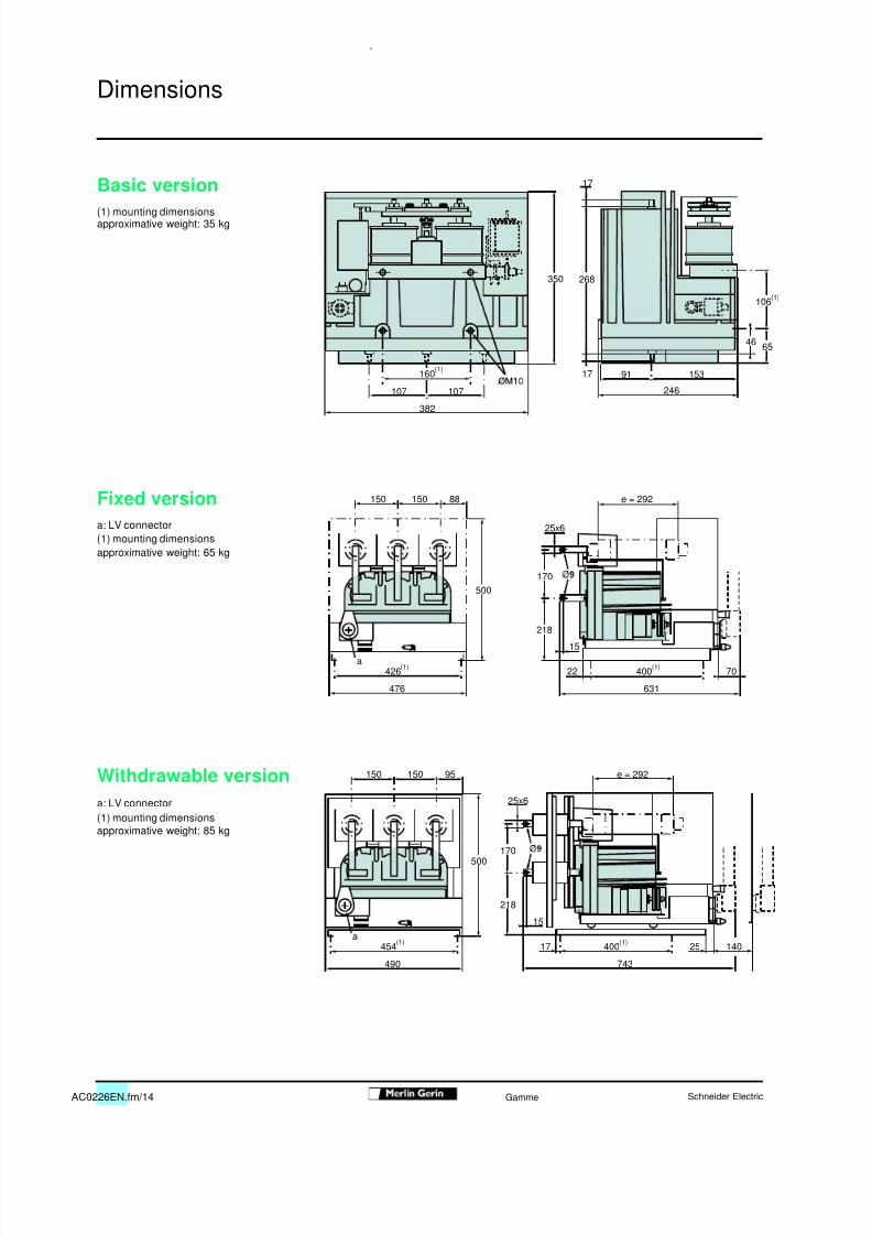
Basic version(1) mounting dimensionsapproximative weight: 35 kg
Fixed versiona: LV connector(1) mounting dimensionsapproximative weight: 65 kg
Withdrawable versiona: LV connector(1) mounting dimensionsapproximative weight: 85 kg
246
91 153
382
160 (1)
107 107
350 268
17
17
6546
106 (1)
426 (1)
476 631
e = 292
400 (1) 7022
15
25x6
a
150150 88
500
218
170
454 (1)
490 743
e = 292
400 (1) 1402517a
150150 95
25x6
15
500170
218
Dimensions
8/16/2019 Contactor Rollarc SF6
http://slidepdf.com/reader/full/contactor-rollarc-sf6 15/24AC0226EN.fm/15Schneider Electric Gamme
0
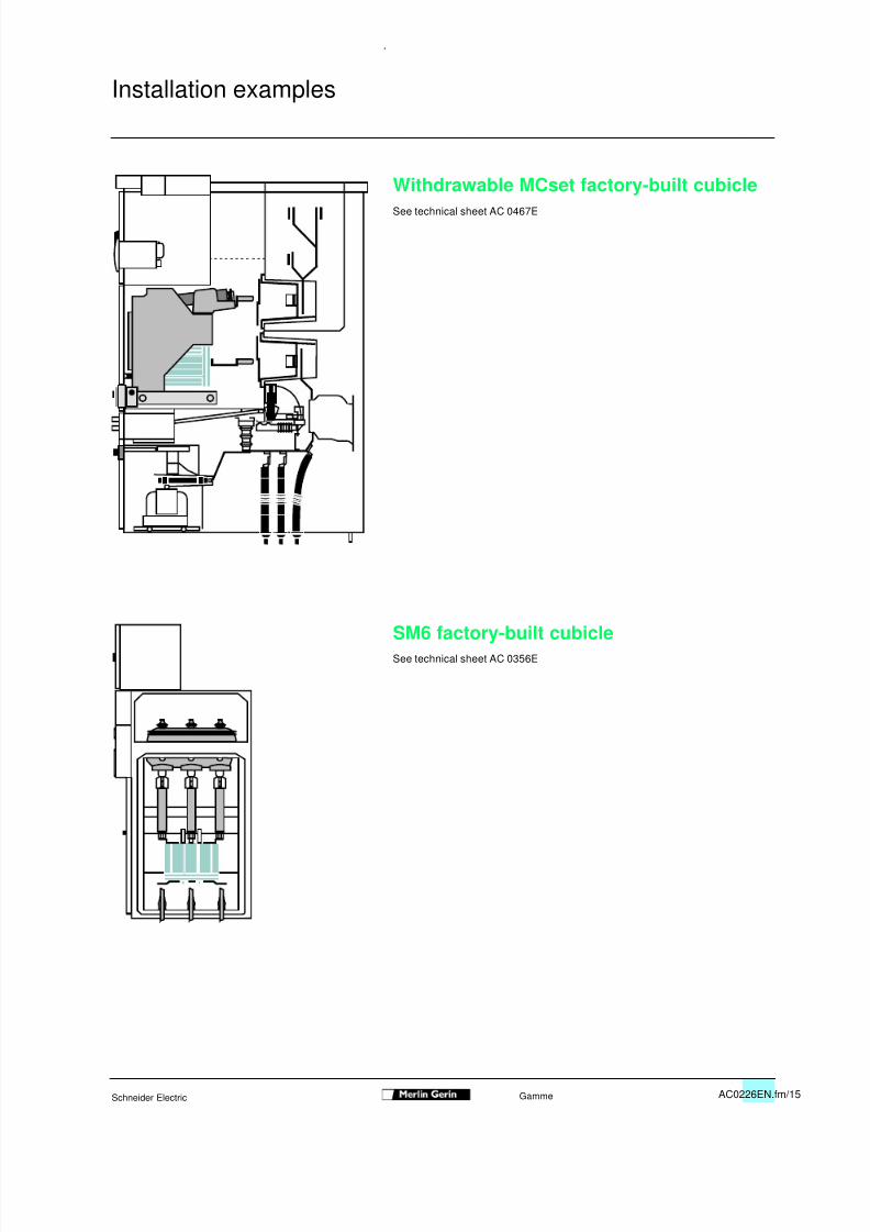
Withdrawable MCset factory-built cubicleSee technical sheet AC 0467E
SM6 factory-built cubicleSee technical sheet AC 0356E
Installation examples
8/16/2019 Contactor Rollarc SF6
http://slidepdf.com/reader/full/contactor-rollarc-sf6 16/24AC0226EN.fm/16 Schneider ElectricGamme
0
Advantages of RollarcThe Rollarc rotating arc contactor is a modern device with enhanced cooling of thearc by forced convection leading to the following advantages:
Long life
This results from: high product reliability, very low wear of the active parts which require no maintenance, the excellent sealing of the enclosure, eliminating the need for subsequent filling.
Mechanical endurance
The operating energy is reduced because arc rotation is directly created by thecurrent to be interrupted.The Rollarc contactor can do 300 000 operations in R400 version and 100 000operations in R400D version.
Electrical enduranceThe long life of the Rollarc is due to the negligible degeneration of the gas and to lowwear of the contacts.The energy dissipated in the arc is low due to: the intrinsic properties of the gas, the short length of the arc, the very short arcing time.Wear of the arcing contacts can be checked without opening the poles. The unit iscapable of breaking all load and short-circuit currents, even in the case of frequentoperation. With very high breaking capacity for a contactor, the Rollarc can be usedin a fuse-contactor assembly capable of protecting any circuit against all types offaults including overloads.
Low switching surgesThe intrinsic properties of the gas and the soft break resulting from this techniquemeans that switching surges are very low.Concerning motor start-up, the unit is free from multiple prestrike and restrikephenomena which could damage the winding insulation.
Operating safety
The Rollarc contactor operates at a low relative pressure of 2.5 bars.
Continuous monitoring of the contactor pressure (optional)A pressure switch actuates a contact in the event of an accidental drop in thepressure of the SF6 gas in the Rollarc unit.
Insensitivity to external conditionsThe Rollarc pole unit provides a totally gas-insulated system. It is a hermeticallysealed enclosure filled with SF6 gas and housing the essential parts.Rollarc is particularly suited to polluted environments such as mines, cement works,etc.
FF
F
F
F
F
S
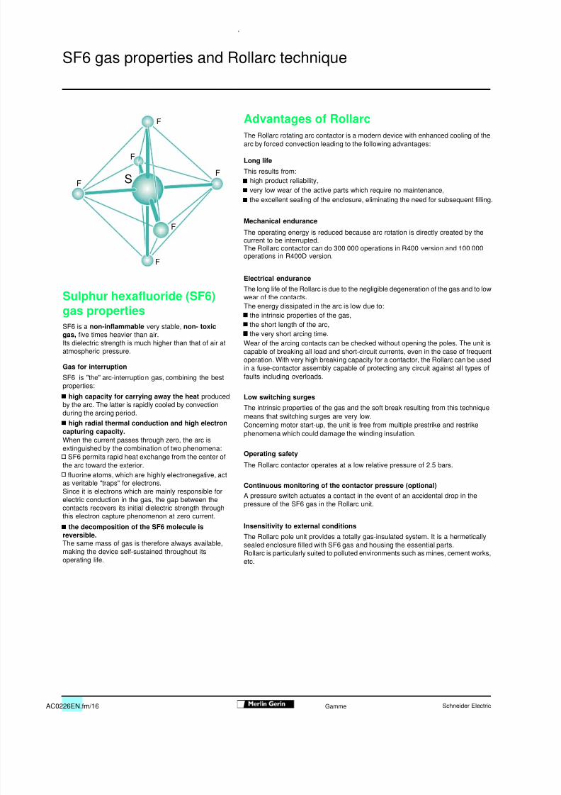
SF6 gas properties and Rollarc technique
Sulphur hexafluoride (SF6)gas propertiesSF6 is a non-inflammable very stable, non- toxicgas, five times heavier than air.Its dielectric strength is much higher than that of air atatmospheric pressure.
Gas for interruption
SF6 is "the" arc-interruption gas, combining the bestproperties: high capacity for carrying away the heat producedby the arc. The latter is rapidly cooled by convectionduring the arcing period. high radial thermal conduction and high electroncapturing capacity.When the current passes through zero, the arc isextinguished by the combination of two phenomena: SF6 permits rapid heat exchange from the center ofthe arc toward the exterior. fluorine atoms, which are highly electronegative, actas veritable "traps" for electrons.Since it is electrons which are mainly responsible forelectric conduction in the gas, the gap between the
contacts recovers its initial dielectric strength throughthis electron capture phenomenon at zero current. the decomposition of the SF6 molecule isreversible.The same mass of gas is therefore always available,making the device self-sustained throughout itsoperating life.
8/16/2019 Contactor Rollarc SF6
http://slidepdf.com/reader/full/contactor-rollarc-sf6 17/24AC0226EN.fm/17Schneider Electric Gamme
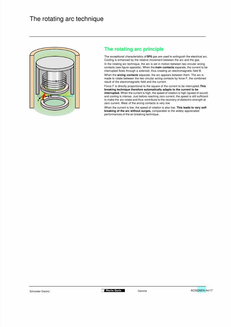
The rotating arc principleThe exceptional characteristics of SF6 gas are used to extinguish the electrical arc.Cooling is enhanced by the relative movement between the arc and the gas.In the rotating arc technique, the arc is set in motion between two circular arcingcontacts (see figure opposite). When the main contacts separate, the current to beinterrupted flows through a solenoid, thus creating an electromagnetic field B.When the arcing contacts separate, the arc appears between them. The arc ismade to rotate between the two circular arcing contacts by force F, the combinedresult of the electromagnetic field and the current.Force F is directly proportional to the square of the current to be interrupted. Thisbreaking technique therefore automatically adapts to the current to beinterrupted. When the current is high, the speed of rotation is high (speed of sound)and cooling is intense. Just before reaching zero current, the speed is still sufficientto make the arc rotate and thus contribute to the recovery of dielectric strength atzero current. Wear of the arcing contacts is very low.
When the current is low, the speed of rotation is also low. This leads to very softbreaking of the arc without surges, comparable to the widely appreciatedperformances of the air breaking technique.
IF
B
I
I
The rotating arc technique
8/16/2019 Contactor Rollarc SF6
http://slidepdf.com/reader/full/contactor-rollarc-sf6 18/24AC0226EN.fm/18 Schneider ElectricGamme
0
Breaking of inductive or capacitive currentsThe Rollarc contactor does not generate voltagesurges.On some switchgear such surges occur during thebreaking of low inductive or capacitive currents andcan damage the insulation of connected devices.With the rotating arc technique, the rotation speed ofthe arc is low for low currents and breaking is softunder all conditions. current chopping: (arc interruption before zerocurrent) the chopping current is always less than 1A,i.e. the voltage surge is very low for the load. multiple prestrikes and restrikesOther phenomena exist that are much more dangerousto the load than the voltage surges resulting from
Results of tests on Rollarcmotor starting busbar busbar capacitance and overvoltage Pu (1) multiplecurrent capacitance (Cb) compensation (Cb+Cc) average standard maxi restrikes
deviation
100A 0.05 mF 1.76 0.18 2.35 none
100A 1.8 mF 1.88 0.13 2.23 none
300A 0.05 mF 1.69 0.10 1.90 none
300A 1.8 mF 1.79 0.09 1.91 none
Example: peak voltage
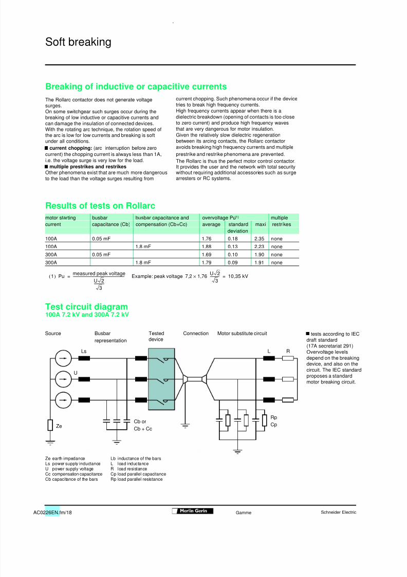
Test circuit diagram100A 7.2 kV and 300A 7.2 kV
tests according to IECdraft standard(17A secretariat 291)Overvoltage levelsdepend on the breakingdevice, and also on the
circuit. The IEC standardproposes a standardmotor breaking circuit.
Ze earth impedanceLs power supply inductanceU power supply voltageCc compensation capacitanceCb capacitance of the bars
Lb inductance of the barsL load inductanceR load resistanceCp load parallel capacitanceRp load parallel resistance
1( ) Pumeasured peak voltage
U 23
--------------------------------------------------------------------------= 7,2 1,76
U 23------------× 10,35 kV=
Source
Ls L R
U
Cb orCb + CcZe
RpCp
ConnectionBusbarrepresentation
Testeddevice
Motor substitute circuit
Soft breaking
current chopping. Such phenomena occur if the devicetries to break high frequency currents.High frequency currents appear when there is adielectric breakdown (opening of contacts is too closeto zero current) and produce high frequency wavesthat are very dangerous for motor insulation.Given the relatively slow dielectric regenerationbetween its arcing contacts, the Rollarc contactoravoids breaking high frequency currents and multipleprestrike and restrike phenomena are prevented.The Rollarc is thus the perfect motor control contactor.It provides the user and the network with total securitywithout requiring additional accessories such as surgearresters or RC systems.
8/16/2019 Contactor Rollarc SF6
http://slidepdf.com/reader/full/contactor-rollarc-sf6 19/24AC0226EN.fm/19Schneider Electric Gamme
0
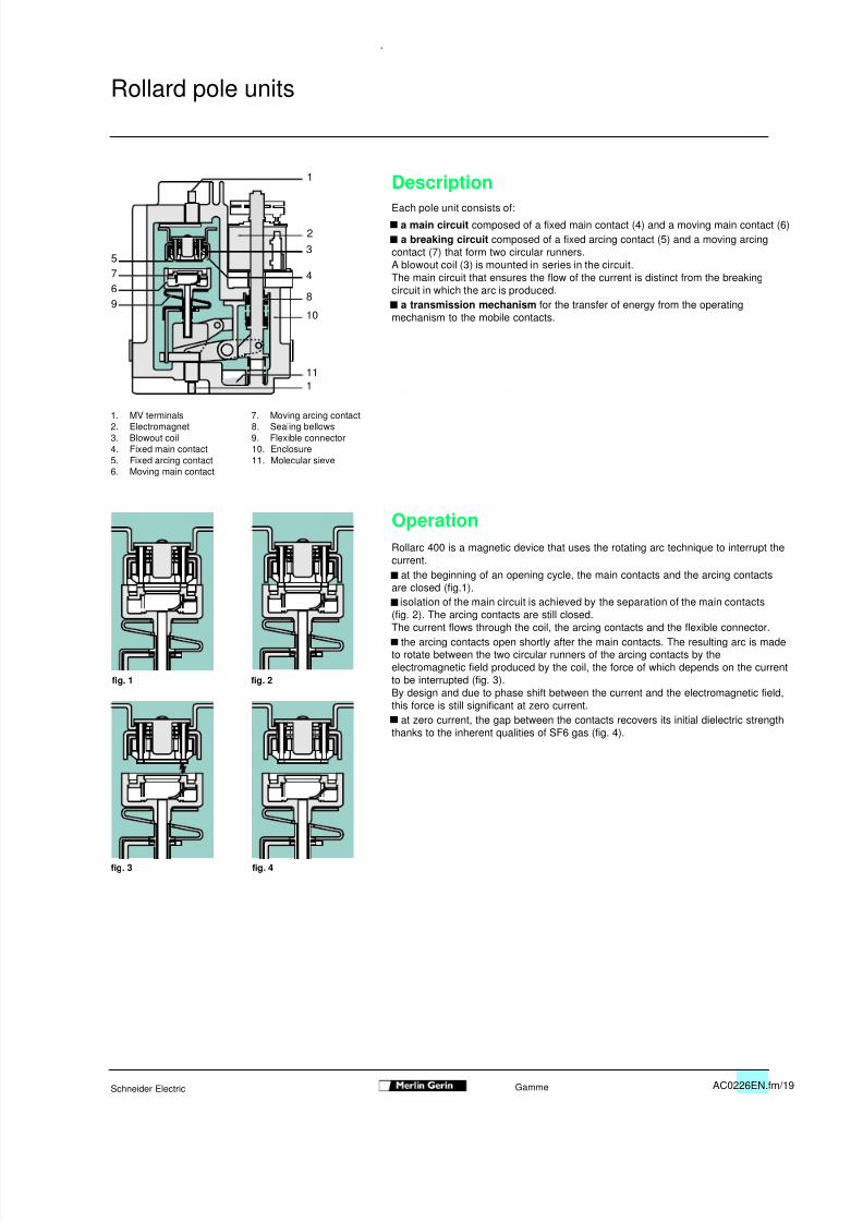
DescriptionEach pole unit consists of:
a main circuit composed of a fixed main contact (4) and a moving main contact (6) a breaking circuit composed of a fixed arcing contact (5) and a moving arcingcontact (7) that form two circular runners.A blowout coil (3) is mounted in series in the circuit.The main circuit that ensures the flow of the current is distinct from the breakingcircuit in which the arc is produced. a transmission mechanism for the transfer of energy from the operatingmechanism to the mobile contacts.
1. MV terminals 7. Moving arcing contact2. Electromagnet 8. Sealing bellows3. Blowout coil 9. Flexible connector4. Fixed main contact 10. Enclosure5. Fixed arcing contact 11. Molecular sieve6. Moving main contact
OperationRollarc 400 is a magnetic device that uses the rotating arc technique to interrupt thecurrent. at the beginning of an opening cycle, the main contacts and the arcing contacts
are closed (fig.1). isolation of the main circuit is achieved by the separation of the main contacts(fig. 2). The arcing contacts are still closed.The current flows through the coil, the arcing contacts and the flexible connector. the arcing contacts open shortly after the main contacts. The resulting arc is madeto rotate between the two circular runners of the arcing contacts by theelectromagnetic field produced by the coil, the force of which depends on the currentto be interrupted (fig. 3).By design and due to phase shift between the current and the electromagnetic field,this force is still significant at zero current. at zero current, the gap between the contacts recovers its initial dielectric strengththanks to the inherent qualities of SF6 gas (fig. 4).
1
23
4
8
10
111
9675
Rollard pole units
fig. 1 fig. 2
fig. 3 fig. 4

8/16/2019 Contactor Rollarc SF6
http://slidepdf.com/reader/full/contactor-rollarc-sf6 20/24AC0226EN.fm/20 Schneider ElectricGamme
Fuse-contactor combinationsPrincipleThe contactor switches the load on and off during normal operation or an overload.The fuse ensures correct interruption of short-circuit currents according to thenetwork short-circuit level. A "fuse-blown" device causes contactor opening.
Economic advantagesFor a short-circuit level of 500 MVA, or of 50 kA at 6 kV, the saving in switchgearcosts is more than 50 % compared to a circuit breaker solution.
Technical advantages
Contactor: high switching rates and greater mechanical endurance than a circuitbreaker.Fuse: current limitation that considerably reduces the thermal and electrodynamiceffects of a fault (fig. 1).
Fuse-contactor assemblyTransformer control and protectionSelect the fuse using the table below
Selection table (ratings in A) (1)
service type of transformer rating (kVA)
voltage (kV) fuse 25 50 100 125 160 200 250 315 400 500 630 800 1000 1250 16003 Fusarc CF 16 25 50 50 63 80 80 125 125 125 160 200 250
3.3 16 25 40 50 50 80 80 100 100 125 160 200 250
5.5 10 16 31.5 31.5 40 50 50 63 80 100 125 125 160 200
6 10 16 25 31.5 40 50 50 63 80 80 125 125 125 160 200
6.6 10 16 25 31.5 40 50 50 63 80 80 100 125 125 160 200
10 6.3 10 16 20 25 31.5 40 50 50 63 80 80 100 100(1) Installation without transformer overload
Prospective current
Limited interrupted current
Fuse-contactor assemblyUtilisation guide
8/16/2019 Contactor Rollarc SF6
http://slidepdf.com/reader/full/contactor-rollarc-sf6 21/24AC0226EN.fm/21Schneider Electric Gamme
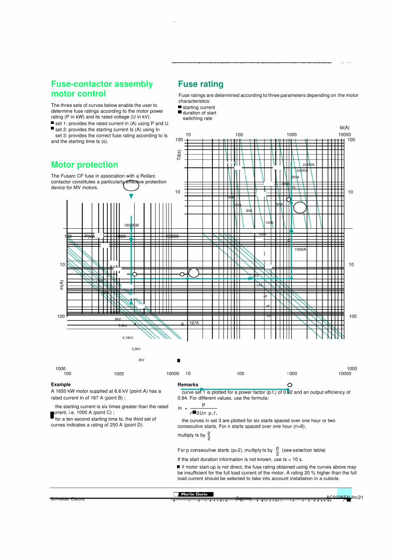
Fuse ratings are determined according to three parameters depending on the motorcharacteristics: starting current duration of start switching rate
Remarks curve set 1 is plotted for a power factor (p.f.) of 0.92 and an output efficiency of0.94. For different values, use the formula:
the curves in set 3 are plotted for six starts spaced over one hour or twoconsecutive starts. For n starts spaced over one hour (n>6),
multiply ts by
For p consecutive starts (p>2), multiply ts by (see selection table)
If the start duration information is not known, use ts = 10 s. if motor start-up is not direct, the fuse rating obtained using the curves above maybe insufficient for the full load current of the motor. A rating 20 % higher than the fullload current should be selected to take into account installation in a cubicle.
10 100 1000 10000100
Id(A)
100
T d ( s )
10
100001000P(kW)100
10
I n ( A )
100
1000100 1000 10000 10 100 1000 10000
10
10
100
1000
1650kW
B 167A
C
1000A
D
x12
x10
x8
x6
50A
63A
80A
100A
125A
160A
200A
250A
2x200A
2x250A
11kV
10kV
4,16kV
3,3kV
3kV
6,6kV
6kV
5,5kV A
x4
In P
n 3Un p . f.--------------------------------- -=
p2---
p2---
0
Fuse ratingFuse-contactor assemblymotor controlThe three sets of curves below enable the user todetermine fuse ratings according to the motor powerrating (P in kW) and its rated voltage (U in kV). set 1: provides the rated current in (A) using P and U set 2: provides the starting current Is (A) using In set 3: provides the correct fuse rating according to Isand the starting time ts (s).
Motor protectionThe Fusarc CF fuse in association with a Rollarccontactor constitutes a particularly effective protectiondevice for MV motors.
ExampleA 1650 kW motor supplied at 6.6 kV (point A) has arated current In of 167 A (point B) ;
the starting current is six times greater than the ratedcurrent, i.e. 1000 A (point C) ; for a ten second starting time ts, the third set ofcurves indicates a rating of 250 A (point D).

8/16/2019 Contactor Rollarc SF6
http://slidepdf.com/reader/full/contactor-rollarc-sf6 22/24AC0226EN.fm/22 Schneider ElectricGamme
0
Notes

8/16/2019 Contactor Rollarc SF6
http://slidepdf.com/reader/full/contactor-rollarc-sf6 23/24AC0226EN.fm/23Schneider Electric Gamme
0

8/16/2019 Contactor Rollarc SF6
http://slidepdf.com/reader/full/contactor-rollarc-sf6 24/24
Schneider Electric SA Postal addressDirection Commerciale France5, rue NadarF-92506 Rueil-Malmaison cedexTel: +33 (0) 1 41 29 82 00Fax: +33 (0) 1 47 51 80 20http://www.schneider-electric.com
As standards, specifications and designs changefrom time to time, always ask for confirmation ofthe information given in this publication.
Design: AXESS (07)RCS Nanterre B 954 503 439 Printing:
REF AC0226/3E
this document has beenprinted on ecological paper .
0