Bio-inspired impact-resistant composites€¦ · Because of the performance and benign processing...
35
L. Grunenfelder, N. Suksangpanya, C. Slinas, G. Milliron, N. Yaraghi, S. Herrera, I. Evans-Lutterodt, S.R. Nutt, P. Zavattieri, D. Kisailus, “Bio-Inspired Impact Resistant Composites”, Acta Biomaterialia 10 [9] 3997-4008 (2014), DOI: http://dx.doi.org/10.1016/j.actbio.2014.03.022 1 Bio-inspired impact-resistant composites L.K. Grunenfelder 1 , N. Suksangpanya 2 , C. Salinas 1 , G. Milliron 1 , N. Yaraghi 3 , S. Herrera 1 , K. Evans-Lutterodt 2 , S.R. Nutt 5 , P. Zavattieri 2 , D. Kisailus 1/3* 1. Department of Chemical and Environmental Engineering, University of California Riverside, Riverside, CA 92521, USA 2. School of Civil Engineering, Purdue University, West Lafayette, IN 47907, USA 3. Materials Science and Engineering Program, University of California Riverside, Riverside, CA 92521, USA 4. National Synchrotron Light Source, Brookhaven National Laboratory, Upton, NY 11973, USA 5. Department of Chemical Engineering and Materials Science, University of Southern California, Los Angeles, CA 90089, USA *Corresponding author: [email protected] Abstract: Through evolutionary processes, biological composites have been optimized to fulfil specific functions. This optimization is exemplified in the mineralized dactyl club of the smashing predator stomatopod (specifically, Odontodactylus scyllarus). This crustacean’s club has been designed to withstand the thousands of high-velocity blows that it delivers to its prey. The endocuticle of this multiregional structure is characterized by a helicoidal arrangement of mineralized fiber layers, an architecture which results in impact resistance and energy absorbance. Here, we apply the helicoidal design strategy observed in the stomatopod club to the fabrication of high-performance carbon fiber–epoxy composites. Through experimental and computational methods, a helicoidal architecture is shown to reduce through-thickness damage propagation in a composite panel during an impact event and result in an increase in toughness. These findings have implications in the design of composite parts for aerospace, automotive and armor applications. Key words: Biomimetic; Composites; Biomineralization; Modeling
Transcript of Bio-inspired impact-resistant composites€¦ · Because of the performance and benign processing...
L. Grunenfelder, N. Suksangpanya, C. Slinas, G. Milliron, N. Yaraghi, S. Herrera, I. Evans-Lutterodt,
S.R. Nutt, P. Zavattieri, D. Kisailus, “Bio-Inspired Impact Resistant Composites”,
Acta Biomaterialia 10 [9] 3997-4008 (2014), DOI: http://dx.doi.org/10.1016/j.actbio.2014.03.022 1
Bio-inspired impact-resistant composites
L.K. Grunenfelder1, N. Suksangpanya2, C. Salinas1, G. Milliron1, N. Yaraghi3, S. Herrera1, K.
Evans-Lutterodt2, S.R. Nutt5, P. Zavattieri2, D. Kisailus1/3*
1. Department of Chemical and Environmental Engineering, University of California Riverside,
Riverside, CA 92521, USA
2. School of Civil Engineering, Purdue University, West Lafayette, IN 47907, USA
3. Materials Science and Engineering Program, University of California Riverside, Riverside,
CA 92521, USA
4. National Synchrotron Light Source, Brookhaven National Laboratory, Upton, NY 11973,
USA
5. Department of Chemical Engineering and Materials Science, University of Southern
California, Los Angeles, CA 90089, USA
*Corresponding author: [email protected]
Abstract: Through evolutionary processes, biological composites have been optimized to fulfil
specific functions. This optimization is exemplified in the mineralized dactyl club of the smashing
predator stomatopod (specifically, Odontodactylus scyllarus). This crustacean’s club has been
designed to withstand the thousands of high-velocity blows that it delivers to its prey. The
endocuticle of this multiregional structure is characterized by a helicoidal arrangement of
mineralized fiber layers, an architecture which results in impact resistance and energy absorbance.
Here, we apply the helicoidal design strategy observed in the stomatopod club to the fabrication of
high-performance carbon fiber–epoxy composites. Through experimental and computational
methods, a helicoidal architecture is shown to reduce through-thickness damage propagation in a
composite panel during an impact event and result in an increase in toughness. These findings have
implications in the design of composite parts for aerospace, automotive and armor applications.
Key words: Biomimetic; Composites; Biomineralization; Modeling
L. Grunenfelder, N. Suksangpanya, C. Slinas, G. Milliron, N. Yaraghi, S. Herrera, I. Evans-Lutterodt,
S.R. Nutt, P. Zavattieri, D. Kisailus, “Bio-Inspired Impact Resistant Composites”,
Acta Biomaterialia 10 [9] 3997-4008 (2014), DOI: http://dx.doi.org/10.1016/j.actbio.2014.03.022 2
1. Introduction
Natural materials are known for their efficiency, performing a range of functions including structural
support as well as mobility and protection, using only the minimum quantities of a limited selection
of constituent materials [1]. These biological materials are most often mineralized composites,
consisting of an organic phase which templates the growth of mineral [2] and [3]. Complex
hierarchical structures containing only a small amount of organic (typically 5–10 wt.%) result in
increased toughness and material properties exceeding those of the inorganic phase alone [1] and
[2]. Because of the performance and benign processing routes of biological materials, natural
composites have received considerable attention in the field of biomimetics [4]. As one example,
researchers over the past several decades have looked to the nacreous layer of mollusk shells as a
model system for toughened biological composites [5] and [6]. Numerous efforts have been
undertaken to mimic the brick-and-mortar structure of nacre [7], [8] and [9]. It was recently shown,
however, that the nacreous structure is vulnerable to attack from a smashing predator known as the
stomatopod or mantis shrimp [10]. This aggressive marine crustacean uses a hammer-like strike to
destroy the shells of mollusks to expose the soft body of the animal.
Stomatopods are divided into two classes, colloquially referred to as spearers and smashers,
dependent upon the dactyl portion of their raptorial feeding appendage (slender barbed spears or
bulbous clubs, respectively) [10], [11], [12] and [13]. Here, we focus on the smashing variety, which
employ a heavily mineralized club to impact the shells of prey animals in a dynamic strike lasting
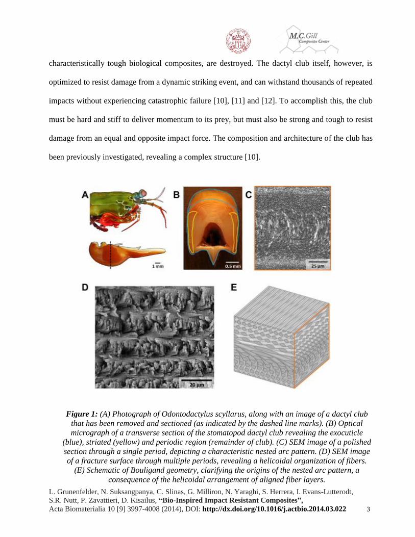
only milliseconds [11] and [14]. The dactyl club of one smashing species, Odontodactylus scyllarus
( Fig. 1A), delivers high-velocity blows reaching accelerations up to 104 m s−2 and speeds of 23 m
s−1 [11] and [14]. Through this hammer mechanism, shells of prey (e.g. mollusks), which consist of
L. Grunenfelder, N. Suksangpanya, C. Slinas, G. Milliron, N. Yaraghi, S. Herrera, I. Evans-Lutterodt,
S.R. Nutt, P. Zavattieri, D. Kisailus, “Bio-Inspired Impact Resistant Composites”,
Acta Biomaterialia 10 [9] 3997-4008 (2014), DOI: http://dx.doi.org/10.1016/j.actbio.2014.03.022 3
characteristically tough biological composites, are destroyed. The dactyl club itself, however, is
optimized to resist damage from a dynamic striking event, and can withstand thousands of repeated
impacts without experiencing catastrophic failure [10], [11] and [12]. To accomplish this, the club
must be hard and stiff to deliver momentum to its prey, but must also be strong and tough to resist
damage from an equal and opposite impact force. The composition and architecture of the club has
been previously investigated, revealing a complex structure [10].
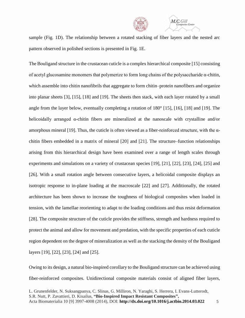
Figure 1: (A) Photograph of Odontodactylus scyllarus, along with an image of a dactyl club
that has been removed and sectioned (as indicated by the dashed line marks). (B) Optical
micrograph of a transverse section of the stomatopod dactyl club revealing the exocuticle
(blue), striated (yellow) and periodic region (remainder of club). (C) SEM image of a polished
section through a single period, depicting a characteristic nested arc pattern. (D) SEM image
of a fracture surface through multiple periods, revealing a helicoidal organization of fibers.
(E) Schematic of Bouligand geometry, clarifying the origins of the nested arc pattern, a
consequence of the helicoidal arrangement of aligned fiber layers.

L. Grunenfelder, N. Suksangpanya, C. Slinas, G. Milliron, N. Yaraghi, S. Herrera, I. Evans-Lutterodt,
S.R. Nutt, P. Zavattieri, D. Kisailus, “Bio-Inspired Impact Resistant Composites”,
Acta Biomaterialia 10 [9] 3997-4008 (2014), DOI: http://dx.doi.org/10.1016/j.actbio.2014.03.022 4
The stomatopod dactyl club, as reported by Weaver et al., is a multiregional biological composite
[10]. The club, like most crustacean exoskeletal elements, is formed through the templating of
mineral growth by an organic scaffold [15]. In the stomatopod, this scaffold consists of fibers of the
long-chain polysaccharide α-chitin. The α-chitin template is mineralized in the exocuticle by
oriented crystalline hydroxyapatite [10]. The exocuticle region, which is the most heavily
mineralized and hardest portion of the club, is termed the impact region, as this is where the club
impacts the prey. The impact region, outlined in blue in Fig. 1B, wraps around the entire club, and
is thickest at the impact surface. Underlying this hard outer layer is the endocuticle, which is
mineralized with amorphous calcium carbonate and calcium phosphate [10]. There are two regions
of interest within the endocuticle, termed the striated and periodic regions. The striated region of the
club, located on either side of the endocuticle (yellow in Fig. 1B), is characterized by closely spaced
striations. This region prevents lateral expansion of the club during a strike [10]. This is achieved
through aligned mineralized fiber layers that form a circumferential band around the club. The
remainder of the club is referred to as the periodic region. While each region of the club plays a role
in the dynamic response of the structure, the periodic region is key to energy dissipation and impact
resistance [10].
When viewed in transverse cross-section (Fig. 1B), the periodic region exhibits a regular pattern of
laminations, a theme commonly observed in arthropod exoskeletons. It is this periodicity that gives
the region its name. Close observation by scanning electron microscopy uncovers a characteristic
nested arc pattern in each laminated region (Fig. 1C). Bouligand has described this architecture in
detail, revealing that the nested arc appearance is an optical illusion of sorts, resulting from a
helicoidal stacking of aligned fiber layers [16] and [17]. This geometry is clarified in a fractured
L. Grunenfelder, N. Suksangpanya, C. Slinas, G. Milliron, N. Yaraghi, S. Herrera, I. Evans-Lutterodt,
S.R. Nutt, P. Zavattieri, D. Kisailus, “Bio-Inspired Impact Resistant Composites”,
Acta Biomaterialia 10 [9] 3997-4008 (2014), DOI: http://dx.doi.org/10.1016/j.actbio.2014.03.022 5
sample (Fig. 1D). The relationship between a rotated stacking of fiber layers and the nested arc
pattern observed in polished sections is presented in Fig. 1E.
The Bouligand structure in the crustacean cuticle is a complex hierarchical composite [15] consisting
of acetyl glucosamine monomers that polymerize to form long chains of the polysaccharide α-chitin,
which assemble into chitin nanofibrils that aggregate to form chitin–protein nanofibers and organize
into planar sheets [3], [15], [18] and [19]. The sheets then stack, with each layer rotated by a small
angle from the layer below, eventually completing a rotation of 180° [15], [16], [18] and [19]. The
helicoidally arranged α-chitin fibers are mineralized at the nanoscale with crystalline and/or
amorphous mineral [19]. Thus, the cuticle is often viewed as a fiber-reinforced structure, with the α-
chitin fibers embedded in a matrix of mineral [20] and [21]. The structure–function relationships
arising from this hierarchical design have been examined over a range of length scales through
experiments and simulations on a variety of crustacean species [19], [21], [22], [23], [24], [25] and
[26]. With a small rotation angle between consecutive layers, a helicoidal composite displays an
isotropic response to in-plane loading at the macroscale [22] and [27]. Additionally, the rotated
architecture has been shown to increase the toughness of biological composites when loaded in
tension, with the lamellae reorienting to adapt to the loading conditions and thus resist deformation
[28]. The composite structure of the cuticle provides the stiffness, strength and hardness required to
protect the animal and allow for movement and predation, with the specific properties of each cuticle
region dependent on the degree of mineralization as well as the stacking the density of the Bouligand
layers [19], [22], [23], [24] and [25].
Owing to its design, a natural bio-inspired corollary to the Bouligand structure can be achieved using
fiber-reinforced composites. Unidirectional composite materials consist of aligned fiber layers,
L. Grunenfelder, N. Suksangpanya, C. Slinas, G. Milliron, N. Yaraghi, S. Herrera, I. Evans-Lutterodt,
S.R. Nutt, P. Zavattieri, D. Kisailus, “Bio-Inspired Impact Resistant Composites”,
Acta Biomaterialia 10 [9] 3997-4008 (2014), DOI: http://dx.doi.org/10.1016/j.actbio.2014.03.022 6
similar to those observed in the crustacean exoskeleton. Through the stacking of unidirectional layers
(plies), a helicoidal composite can be readily obtained. Previous work has highlighted the benefits
of a bio-inspired helicoidal architecture subjected to a range of loading conditions. Changes in ply
orientation are known to influence the toughness and strength of composite materials by altering
damage mechanisms and propagation [29]. Cheng et al. published a comprehensive work on the
flexural stiffness and shear strength of glass fiber-reinforced helicoidal composites, showing the
geometry to have enhanced properties when compared to a quasi-isotropic control sample [27]. Chen
et al., drawing inspiration from a beetle exoskeleton, have reported an increase in the fracture
toughness of a glass fiber-reinforced helicoidal composite architecture compared to that of a
unidirectional control [30]. These studies have shown the benefits of a helicoidal architecture under
static loading conditions. Based on the ability of the stomatopod’s club to withstand multiple high-
energy impacts [10], the goal of this work was to examine the impact resistance and energy
absorption of a helicoidal structure subjected to a dynamic strike, as well as to quantify the residual
strength of the structure following impact damage.
Past studies examining the effect of impact on helicoidal composites have compared performance of
helicoidal samples with a single rotation angle to that of unidirectional or cross-ply controls [31] and
[32]. Here, we examine three helicoidal rotation angles, and compare results to unidirectional as well
as quasi-isotropic controls. A quasi-isotropic layup was chosen as it is an aerospace industry standard
design, and a robust baseline architecture. In this study, the impact damage to each sample was
investigated through experimental observations as well as finite-element analysis. Following impact
testing, the residual strength of the samples was determined through compression testing. This
compression after impact protocol provides information on composite toughness, as it interrogates
the ability of the sample to carry load following the onset of damage. Experimental and model results
L. Grunenfelder, N. Suksangpanya, C. Slinas, G. Milliron, N. Yaraghi, S. Herrera, I. Evans-Lutterodt,
S.R. Nutt, P. Zavattieri, D. Kisailus, “Bio-Inspired Impact Resistant Composites”,
Acta Biomaterialia 10 [9] 3997-4008 (2014), DOI: http://dx.doi.org/10.1016/j.actbio.2014.03.022 7
for fiber-reinforced composites provide insight into toughening mechanisms at work in the
stomatopod dactyl club, and reveal design guidelines for impact-resistant materials.
2. Experimental
2.1 Stomatopod specimen handling and sample preparation
Live specimens of O. scyllarus were obtained from a commercial supplier and housed in a
recirculating artificial seawater system. Specimens ranged in size from approximately 90 to 150 mm
in length. For analysis, dactyl clubs were removed, rinsed in deionized water, and air-dried at room
temperature. To prepare polished sections, clubs were embedded in epoxy (System 2000, Fiberglast,
USA), sectioned with a diamond blade and polished with graded diamond abrasive solutions to a 50
nm grit size. Fractured samples were obtained along the transverse plane of the club using a razor
blade. All samples were sputter coated with a thin layer of platinum and palladium to increase
conductivity and eliminate charging and subsequently imaged using a scanning electron microscope
(XL30-FEG, Philips, USA) with 10 kV accelerating voltage.
2.2 Composite fabrications
The composite material used in this work was a carbon fiber epoxy prepreg with a unidirectional
reinforcement (HexTow® IM7, Hexcel, USA) specifically formulated for out-of-autoclave, vacuum
bag only cure (CYCOM5320-1, Cytec Industries, USA). Five sets of composite panels, each
measuring 350 mm long × 180 mm wide, were fabricated with 48 prepreg layers that were laid up
with different ply orientations. Two sets of standard control composite panels were fabricated. The
first were unidirectional samples, with all plies oriented in the 0° direction. The second were quasi-
L. Grunenfelder, N. Suksangpanya, C. Slinas, G. Milliron, N. Yaraghi, S. Herrera, I. Evans-Lutterodt,
S.R. Nutt, P. Zavattieri, D. Kisailus, “Bio-Inspired Impact Resistant Composites”,
Acta Biomaterialia 10 [9] 3997-4008 (2014), DOI: http://dx.doi.org/10.1016/j.actbio.2014.03.022 8
isotropic panels consisting of prepreg layers oriented in the 0°, ±45° and 90° directions, with the
layup symmetric about the mid-plane. Mid-plane symmetry is critical in composite manufacturing,
to prevent the warping that can occur in non-symmetric layups because of residual stresses that
develop during elevated temperature cure [27] and [29]. In addition to the unidirectional and quasi-
isotropic controls, three helicoidal (Fig. 2A) structures were fabricated with rotation angles of 7.8°,
16.3° and 25.7°. These rotation angles were chosen such that all panels had a consistent thickness,
and mid-plane symmetry could be maintained. Details of the composite layup schemes are presented
in Table 1.
L. Grunenfelder, N. Suksangpanya, C. Slinas, G. Milliron, N. Yaraghi, S. Herrera, I. Evans-Lutterodt,
S.R. Nutt, P. Zavattieri, D. Kisailus, “Bio-Inspired Impact Resistant Composites”,
Acta Biomaterialia 10 [9] 3997-4008 (2014), DOI: http://dx.doi.org/10.1016/j.actbio.2014.03.022 9
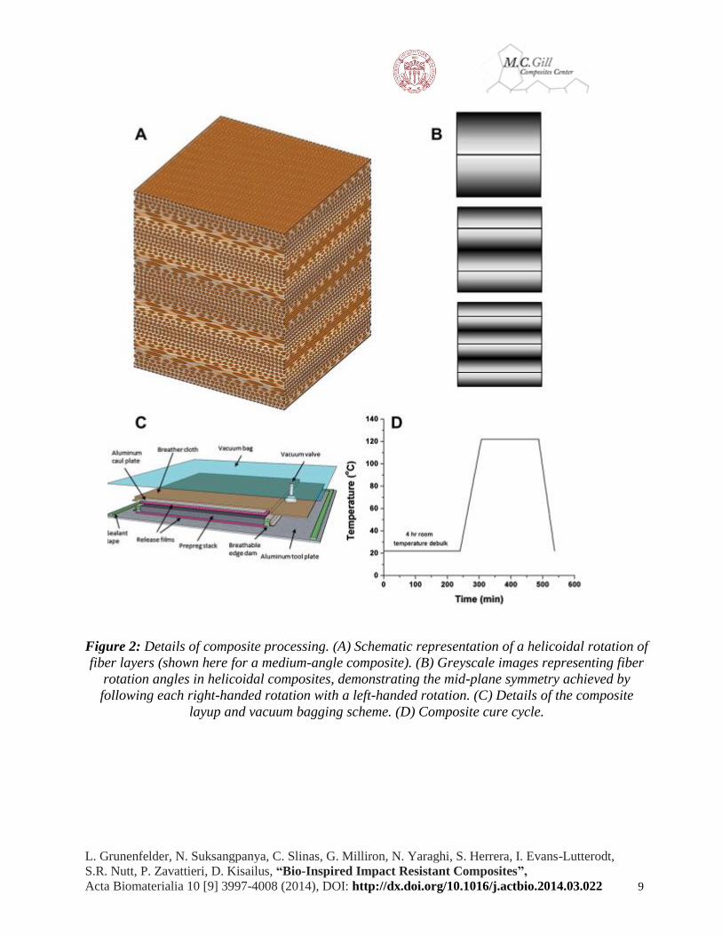
Figure 2: Details of composite processing. (A) Schematic representation of a helicoidal rotation of
fiber layers (shown here for a medium-angle composite). (B) Greyscale images representing fiber
rotation angles in helicoidal composites, demonstrating the mid-plane symmetry achieved by
following each right-handed rotation with a left-handed rotation. (C) Details of the composite
layup and vacuum bagging scheme. (D) Composite cure cycle.

L. Grunenfelder, N. Suksangpanya, C. Slinas, G. Milliron, N. Yaraghi, S. Herrera, I. Evans-Lutterodt,
S.R. Nutt, P. Zavattieri, D. Kisailus, “Bio-Inspired Impact Resistant Composites”,
Acta Biomaterialia 10 [9] 3997-4008 (2014), DOI: http://dx.doi.org/10.1016/j.actbio.2014.03.022
10
Table 1: Layup details for composite laminates.
Sample Layup
Unidirectional [0]48
Quasi-isotropic [0/±45/90]6s
Small angle [0/7.8/…/180]s
Medium angle [0/16.3/…/180]2s
Large angle [0/25.7/…/180]3s
For all helicoidal samples, prepreg plies were cut to specific angles prior to layup. All samples were
fabricated to be symmetric about the mid-plane, meaning each right-handed rotation was
immediately followed by a left-handed rotation (fiber angle in each sample is represented by the
greyscale images in Fig. 2B).
After layup, samples were vacuum bagged (>28 in. Hg) according to the layup schematic in Fig. 2C.
Bagged samples were debulked for 4 h at room temperature to remove trapped air. After the room
temperature vacuum hold, samples were cured according to the manufacturer’s recommended cure
cycle (Fig. 2D). All samples were subjected to a freestanding post-cure cycle consisting of a ramp
at 2 °C min−1 to 121 °C, immediately followed by a ramp at 0.6 °C min−1 to 177 °C. This lower ramp
rate was employed to avoid crossing the instantaneous glass transition temperature of the resin and
devitrifying the resin. The samples were held at 177 °C for 2 h. Samples were finally cooled back to
room temperature at 2 °C min−1.
L. Grunenfelder, N. Suksangpanya, C. Slinas, G. Milliron, N. Yaraghi, S. Herrera, I. Evans-Lutterodt,
S.R. Nutt, P. Zavattieri, D. Kisailus, “Bio-Inspired Impact Resistant Composites”,
Acta Biomaterialia 10 [9] 3997-4008 (2014), DOI: http://dx.doi.org/10.1016/j.actbio.2014.03.022
11
2.3 Analysis and mechanical testing of composites
After curing, composite samples measuring 6.5 mm in thickness were machined to dimensions of
100 mm × 150 mm using a water-fed tile saw. The dimensions of each sample were measured with
calipers and recorded. Polished cross-sections of each sample were prepared by embedding in epoxy
(SamplKwick, Buehler, USA) and polishing with graded silicon carbide sandpapers down to a grit
of 1200 (15 μm). Cross-sectional microstructures were examined using a digital stereo microscope
(Keyence VHX-600E).
To determine the toughness of each composite, samples were subjected to a standard compression
after impact testing protocol. Three replicates were tested for each layup configuration. Impact
testing was performed in accordance with ASTM D7136 [33], using a drop weight impact testing
system equipped with a hemispherical tip, with a diameter of 16 mm (9250HV, Instron, USA),
providing an impact energy of 100 J. During impact, samples were held in place by upper and lower
clamp plates, with 76 mm diameter circular holes at the center. After impact, photographs of each
sample were obtained to examine external damage, and dent depth was measured using a depth
gauge. Internal damage was probed using a non-destructive ultrasound technique (Ultrasonic C-
scans) using a 10 MHz water-coupled transducer in reflected mode (UPK-T36, NDT Automation,
USA). Following ultrasound analysis, samples were end-loaded into a specialized fixture and
compressed to failure, following ASTM D7173 [34]. The fixture prevents global buckling of the
sample during testing, leading to failure as a result of propagation of cracks and delaminations [35].
A displacement-controlled compressive loading of 1.25 mm min−1 was applied using a load frame
with a 250 kN capacity (5585H, Instron, USA). Load and displacement were recorded during testing
and used to calculate residual strength.

L. Grunenfelder, N. Suksangpanya, C. Slinas, G. Milliron, N. Yaraghi, S. Herrera, I. Evans-Lutterodt,
S.R. Nutt, P. Zavattieri, D. Kisailus, “Bio-Inspired Impact Resistant Composites”,
Acta Biomaterialia 10 [9] 3997-4008 (2014), DOI: http://dx.doi.org/10.1016/j.actbio.2014.03.022
12
2.4. Modeling of impact damage
Experimental data from drop tower testing was used to validate models, allowing for the prediction
of failure mechanisms and examination of damage behavior in each specimen type under high-
impact loading. Computational modeling of a drop tower test following ASTM D7136 on IM7/5320-
1 composite specimens was performed using the finite-element method with an explicit solver [36].
Most of the mechanical properties of the unidirectional prepreg used in this work were obtained
directly from manufacturer data sheets (personal communication), except for the critical energy
release rate values which were adopted from other works [37] and [38]. These properties are listed
in Table 2.
Table 2: Composite mechanical properties.
E1 (GPa) E2 (GPa) ν G12 (GPa) G23 (GPa) ρ (Vf = 0.67)
(kg m−3)
153.75 9.7 0.344 5.79 2.9 1624.9
(MPa) (MPa) (MPa) (MPa) τL (MPa) (MPa) Gcr,L (kN
m-1)
Gcr,T (kN
m-1)
2489.01 1985.69 81 312 125.48 111.7 40 0.3
The quasi-isotropic control samples and three sets of helicoidal composite specimens examined in
this study were modeled at the ply level. Each unidirectional layer within the composite samples was
modeled individually as continuum plane stress shell elements with the thickness being equal to the
average lamina thickness (0.135 mm) and the average element size near the impact region being
0.08 mm. Fiber orientation was assigned to each ply based on the layup details of each sample

L. Grunenfelder, N. Suksangpanya, C. Slinas, G. Milliron, N. Yaraghi, S. Herrera, I. Evans-Lutterodt,
S.R. Nutt, P. Zavattieri, D. Kisailus, “Bio-Inspired Impact Resistant Composites”,
Acta Biomaterialia 10 [9] 3997-4008 (2014), DOI: http://dx.doi.org/10.1016/j.actbio.2014.03.022
13
(see Table 1). The total model consisted of one layer with 144 integration points. In this layer, each
ply of the composite is represented by three adjacent points, thereby accounting for all 48 plies (Fig.
3). In total, the model consisted of 35,879 nodes and 35,853 large-strain shell elements (S4R). This
modeling approach allows the simulation to capture the variations of damage and stress states in the
model as a whole, as well as in each individual ply.
Figure 3: Finite-element model of a drop tower test and details of the helicoidal composite panel.
The indentation head of the drop tower was considered as a rigid body with a mass of 4.91 kg and
providing an impact energy of 100 J (based on experimental conditions). In experimental
observations, no sliding was observed between the composite and the clamp plates. As such, the
clamps were modeled with fixed boundary conditions on the contact surfaces between the clamps
and the top and bottom surfaces of the specimens.
3. Results
The helicoidal architecture found in the endocuticle of the stomatopod dactyl club was used as
inspiration for the design of impact-resistant carbon fiber–epoxy composites. Samples of the dactyl
club were examined to determine the angle of rotation throughout the entire endocuticle and
ascertain details of the complex architecture of the club. Bio-inspired composites were then
L. Grunenfelder, N. Suksangpanya, C. Slinas, G. Milliron, N. Yaraghi, S. Herrera, I. Evans-Lutterodt,
S.R. Nutt, P. Zavattieri, D. Kisailus, “Bio-Inspired Impact Resistant Composites”,
Acta Biomaterialia 10 [9] 3997-4008 (2014), DOI: http://dx.doi.org/10.1016/j.actbio.2014.03.022
14
fabricated and tested. The responses of the carbon fiber samples were examined through
experimental and analytical approaches, and related to the impact response in the organism.
3.1. Analysis of a biological hammer
The energy-absorbing periodic region of the stomatopod club is the focus of the present study.
Transverse polished sections of the club provide information on fracture behavior in the sample.
Cracks in the stomatopod club nest within the periodic region (as shown in Fig. 4A and in greater
detail in Fig. 1C). No cracks are observed to propagate through the entire sample. This is a
consequence of the Bouligand architecture in the periodic region, and will be discussed in more
detail in Section 6.

L. Grunenfelder, N. Suksangpanya, C. Slinas, G. Milliron, N. Yaraghi, S. Herrera, I. Evans-Lutterodt,
S.R. Nutt, P. Zavattieri, D. Kisailus, “Bio-Inspired Impact Resistant Composites”,
Acta Biomaterialia 10 [9] 3997-4008 (2014), DOI: http://dx.doi.org/10.1016/j.actbio.2014.03.022
15
Figure 4: (A) Overview of the periodic region, showing change in pitch length from the exterior
inward. (B) Pitch length as a function of distance through the center of the club from the impact
region inward. (C) Fractured surface highlighting out-of-plane mineralized fiber bundles. (D)
Polished section of a large pitch region. (E) Polished section of small pitch region. Yellow lines
used in (D) and (E) as guides to show arching in samples.
While a helicoidal architecture is a common feature of the crustacean cuticle, there are two unique
aspects to the rotation in the stomatopod dactyl club. The first observation is that the length of a 180°
rotation (pitch) is larger than that observed in most crustaceans. Secondly, the dactyl club displays
a pitch gradient varying from ∼115 μm near the impact surface to ∼30 μm at the interior of the club
(Fig. 4B) as measured using image analysis software. Interestingly, there is an initial increase in
L. Grunenfelder, N. Suksangpanya, C. Slinas, G. Milliron, N. Yaraghi, S. Herrera, I. Evans-Lutterodt,
S.R. Nutt, P. Zavattieri, D. Kisailus, “Bio-Inspired Impact Resistant Composites”,
Acta Biomaterialia 10 [9] 3997-4008 (2014), DOI: http://dx.doi.org/10.1016/j.actbio.2014.03.022
16
pitch length, occurring over the four periods closest to the impact region, followed by a decrease in
the pitch length. This decrease is fairly linear until reaching an asymptotic threshold of ∼30–35 μm.
The pitch change observed in the club indicates that either the angle of rotation is increasing moving
from the impact region inward, or the spacing between fiber layers is decreasing.
High-resolution scanning electron microscopy (SEM) of a transverse fractured section in the
periodic region reveals the presence of mineralized fiber bundles (Fig. 4C). These bundles measure
1.13 ± 0.02 μm in thickness (with individual fibers ranging from 20 to 50 nm in diameter). In
addition, round or elliptical features are observed in polished sections within the periodic region
(Fig. 4D and E) at the boundary of each pitch, where fibers are oriented perpendicular to the field of
view. We use these features to define the thickness of each mineralized layer. Subsequent layers are
oriented at an angle to the plane of view until a rotation of 180° is completed. Using image analysis,
these features are measured to be 1.14 ± 0.17 μm in diameter, and are consistent in size throughout
the stomatopod club, regardless of pitch length (see Fig. 4D and E). This measurement is consistent
with the thickness of a bundle of mineralized fibers (Fig. 4C), indicating that each bundle defines a
unidirectional sheet in the Bouligand architecture. By defining each layer as having a thickness of 1
μm, the angle of rotation throughout the periodic region was calculated to range from 1.6° in the
outermost region to 6.2° in the inner region of the club. While this calculation of rotation angle is an
approximation, it gives a first estimate to the range of angles present in the club.
4. Biologically inspired composites
The aim of this work was to apply the helicoidal design strategy observed in the stomatopod dactyl
club to the fabrication of high-performance composite panels. The rotational angles examined in our
biomimetic composites, 7.8°, 16.3° and 25.7°, were constrained by the need to maintain a consistent
L. Grunenfelder, N. Suksangpanya, C. Slinas, G. Milliron, N. Yaraghi, S. Herrera, I. Evans-Lutterodt,
S.R. Nutt, P. Zavattieri, D. Kisailus, “Bio-Inspired Impact Resistant Composites”,
Acta Biomaterialia 10 [9] 3997-4008 (2014), DOI: http://dx.doi.org/10.1016/j.actbio.2014.03.022
17
number of layers and impose mid-plane symmetry. These angles were, in most cases, larger than
those calculated for the stomatopod club, with the smallest angle (7.8°) providing a close match to
the innermost region of the club. Despite the inability to directly measure or replicate the angles
present in the club, the use of multiple angles provides a means of determining the influence of a
small vs. large angle of rotation on material response.
The mechanical properties of helicoidal composites were compared to those of control layups
(unidirectional, quasi-isotropic) to examine the influence of the rotated design on impact resistance.
With mid-plane symmetry imposed, all samples remained flat after curing, and no warping was
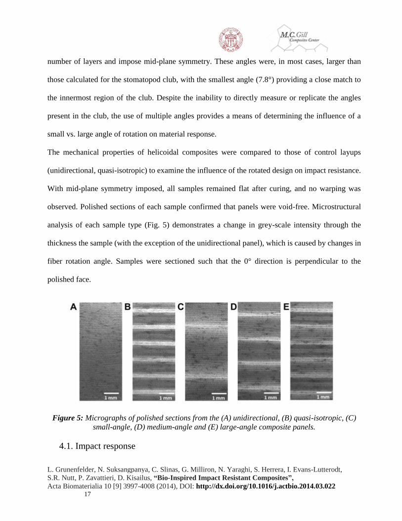
observed. Polished sections of each sample confirmed that panels were void-free. Microstructural
analysis of each sample type (Fig. 5) demonstrates a change in grey-scale intensity through the
thickness the sample (with the exception of the unidirectional panel), which is caused by changes in
fiber rotation angle. Samples were sectioned such that the 0° direction is perpendicular to the
polished face.
Figure 5: Micrographs of polished sections from the (A) unidirectional, (B) quasi-isotropic, (C)
small-angle, (D) medium-angle and (E) large-angle composite panels.
4.1. Impact response

L. Grunenfelder, N. Suksangpanya, C. Slinas, G. Milliron, N. Yaraghi, S. Herrera, I. Evans-Lutterodt,
S.R. Nutt, P. Zavattieri, D. Kisailus, “Bio-Inspired Impact Resistant Composites”,
Acta Biomaterialia 10 [9] 3997-4008 (2014), DOI: http://dx.doi.org/10.1016/j.actbio.2014.03.022
18
Samples measuring 100 mm × 150 mm were subjected to high-energy (100 J) impact using a drop
tower. Following the impact event, the extent of damage to the panels was assessed by examining
visible external damage, measuring the depth of the indent, and performing ultrasound scans of the
internal damage. Three samples were tested for each layup condition, yielding consistent results.
The images in Fig. 6A–E are representative of the damage type for each layup configuration.
Initially, external damage was examined on the backside of the panel, opposite the impact event.
The high-energy impact produced catastrophic failure in the unidirectional control samples, resulting
in a splitting of the panels (Fig. 6A). All other samples, however, showed varying degrees of impact
damage. For the quasi-isotropic controls (Fig. 6B) the impact event resulted in puncture through the
backside of the panels, accompanied by fiber breakage. The helicoidal samples, in contrast, did not
show indentation puncture, but rather splits on the back surface. It is of note that these splits did not,
in all cases, occur immediately opposite to the impact location, but were rather displaced from the
central impact point. For the small-angle composite panels, large cracks were observed along the
long edge of the sample (Fig. 6C).
L. Grunenfelder, N. Suksangpanya, C. Slinas, G. Milliron, N. Yaraghi, S. Herrera, I. Evans-Lutterodt,
S.R. Nutt, P. Zavattieri, D. Kisailus, “Bio-Inspired Impact Resistant Composites”,
Acta Biomaterialia 10 [9] 3997-4008 (2014), DOI: http://dx.doi.org/10.1016/j.actbio.2014.03.022
19
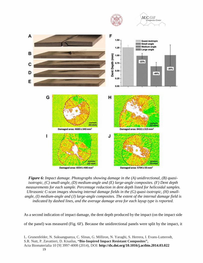
Figure 6: Impact damage. Photographs showing damage in the (A) unidirectional, (B) quasi-
isotropic, (C) small-angle, (D) medium-angle and (E) large-angle composites. (F) Dent depth
measurements for each sample. Percentage reduction in dent depth listed for helicoidal samples.
Ultrasonic C-scan images showing internal damage fields in the (G) quasi-isotropic, (H) small-
angle, (I) medium-angle and (J) large-angle composites. The extent of the internal damage field is
indicated by dashed lines, and the average damage area for each layup type is reported.
As a second indication of impact damage, the dent depth produced by the impact (on the impact side
of the panel) was measured (Fig. 6F). Because the unidirectional panels were split by the impact, it
L. Grunenfelder, N. Suksangpanya, C. Slinas, G. Milliron, N. Yaraghi, S. Herrera, I. Evans-Lutterodt,
S.R. Nutt, P. Zavattieri, D. Kisailus, “Bio-Inspired Impact Resistant Composites”,
Acta Biomaterialia 10 [9] 3997-4008 (2014), DOI: http://dx.doi.org/10.1016/j.actbio.2014.03.022
20
was not possible to measure dent depths for those panels. In all cases, the helicoidal samples showed
a reduced dent depth when compared to the quasi-isotropic controls. The percentage reduction in
depth is reported on the plot in Fig. 6F. From dent depth measurements, the medium angle
composites showed the greatest reduction in external indent damage, with an average depth
reduction of 49%.
The internal damage field caused by impact was investigated using a non-destructive pulse–echo
ultrasound technique. Scans were performed in a water tank using a 10 MHz transducer in reflected
mode. Representative ultrasonic C-scan images are presented in Fig. 6G–I. The color scale on the
images represents the reflected signal intensity, with green indicating a reflected intensity of
approximately 90%, yellow 50% and red 10%. White areas are empty pixels, resulting from regions
where no signal was detected (indicating a high degree of internal damage). The extent of the internal
damage field in the region scanned is marked with dashed lines in Fig. 6, and average area of the
damaged region for each layup configuration is reported. The ultrasound data reveals that the quasi-
isotropic control samples (Fig. 6G) have the smallest internal damage field. The damage spread in
the control samples is also symmetric. The helicoidal samples, however, show a more widespread
and asymmetric damage field. The extent of the lateral spread of damage is most pronounced in the
small-angle composites (Fig. 6H), and decreases with increasing ply rotation angle.
4.2. Residual strength
Following analysis of impact damage, samples were end-loaded and compressed to failure. This
compression after impact test protocol is a composite industry standard test for toughness, as it
interrogates the ability of the sample to support a load after the onset of damage. Load vs.
displacement data was recorded for each panel type (Fig. 7A). Compressive residual strength was
L. Grunenfelder, N. Suksangpanya, C. Slinas, G. Milliron, N. Yaraghi, S. Herrera, I. Evans-Lutterodt,
S.R. Nutt, P. Zavattieri, D. Kisailus, “Bio-Inspired Impact Resistant Composites”,
Acta Biomaterialia 10 [9] 3997-4008 (2014), DOI: http://dx.doi.org/10.1016/j.actbio.2014.03.022
21
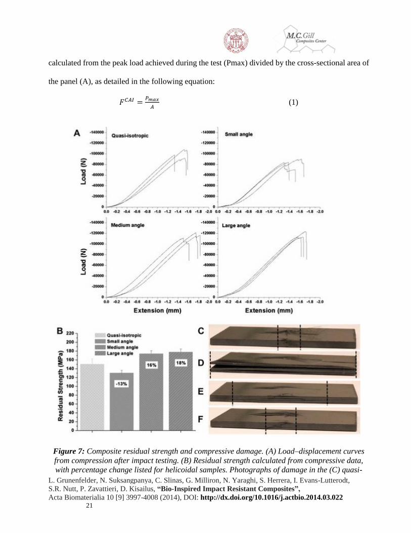
calculated from the peak load achieved during the test (Pmax) divided by the cross-sectional area of
the panel (A), as detailed in the following equation:
𝐹𝐶𝐴𝐼 =𝑃𝑚𝑎𝑥
𝐴 (1)
Figure 7: Composite residual strength and compressive damage. (A) Load–displacement curves
from compression after impact testing. (B) Residual strength calculated from compressive data,
with percentage change listed for helicoidal samples. Photographs of damage in the (C) quasi-

L. Grunenfelder, N. Suksangpanya, C. Slinas, G. Milliron, N. Yaraghi, S. Herrera, I. Evans-Lutterodt,
S.R. Nutt, P. Zavattieri, D. Kisailus, “Bio-Inspired Impact Resistant Composites”,
Acta Biomaterialia 10 [9] 3997-4008 (2014), DOI: http://dx.doi.org/10.1016/j.actbio.2014.03.022
22
isotropic, (D) small-angle, (E) medium-angle and (F) large-angle composites after compression
tests.
Details of the residual strength in each panel are presented (Fig. 7B) with the percentage change in
residual strength vs. the quasi-isotropic controls indicated for helicoidal samples. The small-angle
panels reached the lowest loads during compression and thus have the lowest residual strength. The
medium- and large-angle panels, however, show a marked increase in residual strength when
compared to the quasi-isotropic controls (16% and 18%, respectively, Fig. 7B).
After compressive failure, the damage behavior in each composite was assessed (Fig. 7C–F). Dotted
black lines mark the lateral extent of visible cracking. For the quasi-isotropic controls (Fig. 7C), the
damage is localized to a narrow region directly in line with the impact event. However, the damage
in the helicoidal samples is spread laterally to varying degrees. The small-angle composites, which
showed edge cracking following impact, exhibit damage across the entire length of the test specimen,
and show considerable cracking (Fig. 7D). In the medium-angle composites, cracks are distributed
laterally, with damage propagating farther outward in lower plies. The large-angle composites show
the narrowest damage window for the helicoidal samples, though the damage is still more disbursed
than in the case of the quasi-isotropic controls. To obtain more information about the damage
mechanisms at work in helicoidal composites, computational models were employed.
5. Modeling of a dynamic strike
For the computational modeling, the composite material is assumed to have a transversely isotropic
elastic response until failure. Using a finite-element framework, damage can therefore be modeled
with Hashin progressive failure criteria [39]. This method has been verified by Icten and Karakuzu
through finite-element analysis of pinned-joint carbon–epoxy composite panels and comparison
with experimental data [40]. The Hashin damage model allows damage to take place in the fiber and
L. Grunenfelder, N. Suksangpanya, C. Slinas, G. Milliron, N. Yaraghi, S. Herrera, I. Evans-Lutterodt,
S.R. Nutt, P. Zavattieri, D. Kisailus, “Bio-Inspired Impact Resistant Composites”,
Acta Biomaterialia 10 [9] 3997-4008 (2014), DOI: http://dx.doi.org/10.1016/j.actbio.2014.03.022
23
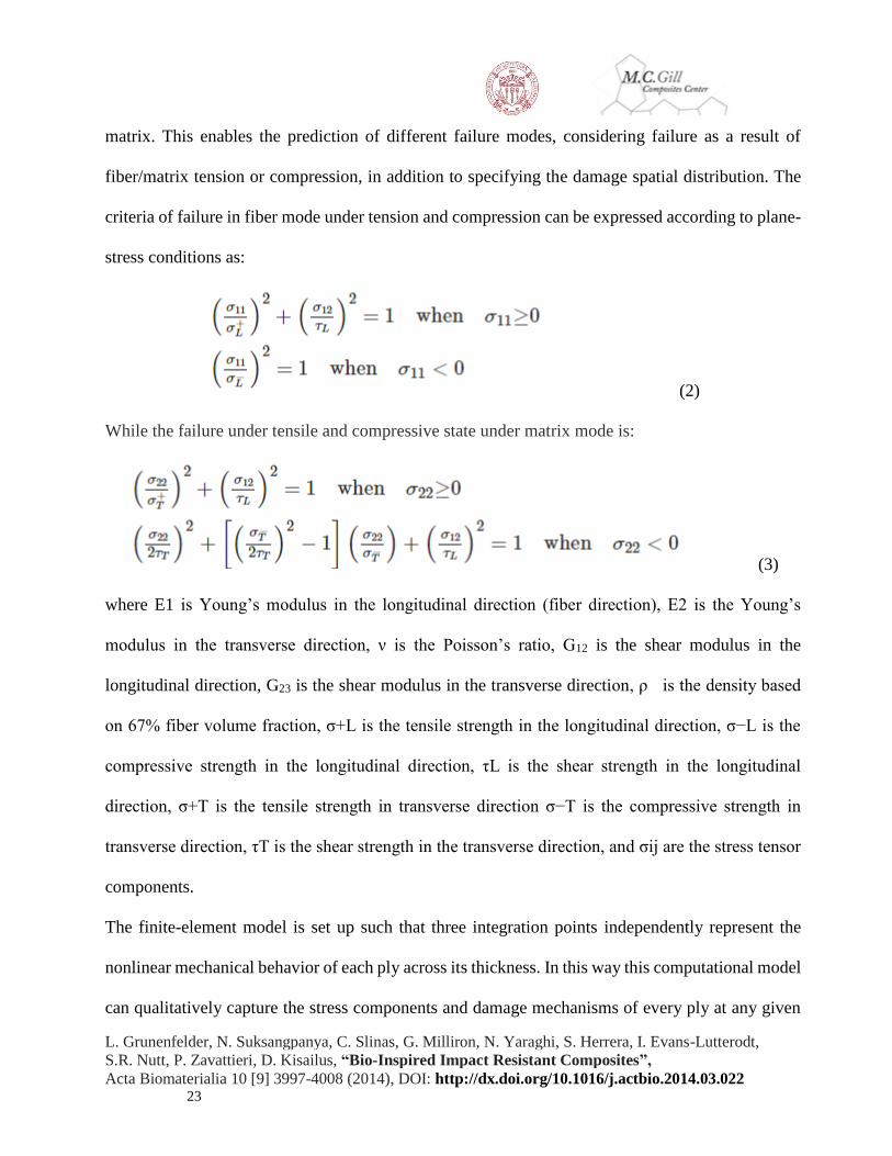
matrix. This enables the prediction of different failure modes, considering failure as a result of
fiber/matrix tension or compression, in addition to specifying the damage spatial distribution. The
criteria of failure in fiber mode under tension and compression can be expressed according to plane-
stress conditions as:
(2)
While the failure under tensile and compressive state under matrix mode is:
(3)
where E1 is Young’s modulus in the longitudinal direction (fiber direction), E2 is the Young’s
modulus in the transverse direction, ν is the Poisson’s ratio, G12 is the shear modulus in the
longitudinal direction, G23 is the shear modulus in the transverse direction, ρ is the density based
on 67% fiber volume fraction, σ+L is the tensile strength in the longitudinal direction, σ−L is the
compressive strength in the longitudinal direction, τL is the shear strength in the longitudinal
direction, σ+T is the tensile strength in transverse direction σ−T is the compressive strength in
transverse direction, τT is the shear strength in the transverse direction, and σij are the stress tensor
components.
The finite-element model is set up such that three integration points independently represent the
nonlinear mechanical behavior of each ply across its thickness. In this way this computational model
can qualitatively capture the stress components and damage mechanisms of every ply at any given
L. Grunenfelder, N. Suksangpanya, C. Slinas, G. Milliron, N. Yaraghi, S. Herrera, I. Evans-Lutterodt,
S.R. Nutt, P. Zavattieri, D. Kisailus, “Bio-Inspired Impact Resistant Composites”,
Acta Biomaterialia 10 [9] 3997-4008 (2014), DOI: http://dx.doi.org/10.1016/j.actbio.2014.03.022
24
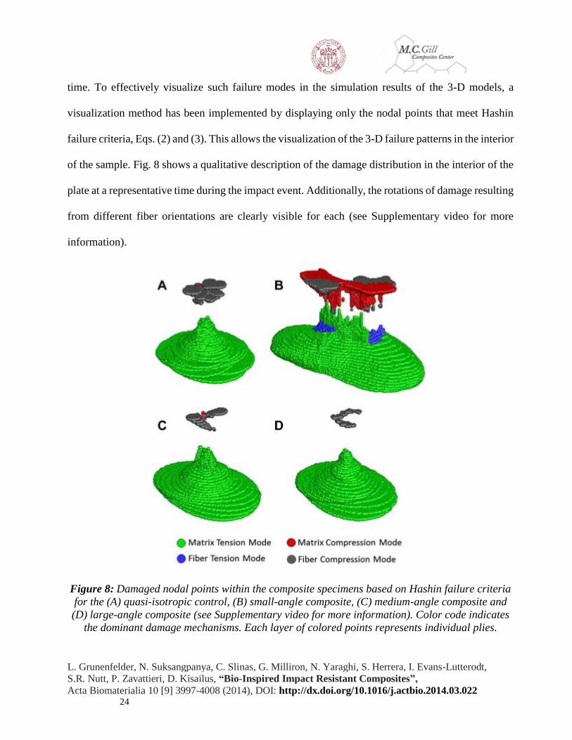
time. To effectively visualize such failure modes in the simulation results of the 3-D models, a
visualization method has been implemented by displaying only the nodal points that meet Hashin
failure criteria, Eqs. (2) and (3). This allows the visualization of the 3-D failure patterns in the interior
of the sample. Fig. 8 shows a qualitative description of the damage distribution in the interior of the
plate at a representative time during the impact event. Additionally, the rotations of damage resulting
from different fiber orientations are clearly visible for each (see Supplementary video for more
information).
Figure 8: Damaged nodal points within the composite specimens based on Hashin failure criteria
for the (A) quasi-isotropic control, (B) small-angle composite, (C) medium-angle composite and
(D) large-angle composite (see Supplementary video for more information). Color code indicates
the dominant damage mechanisms. Each layer of colored points represents individual plies.
L. Grunenfelder, N. Suksangpanya, C. Slinas, G. Milliron, N. Yaraghi, S. Herrera, I. Evans-Lutterodt,
S.R. Nutt, P. Zavattieri, D. Kisailus, “Bio-Inspired Impact Resistant Composites”,
Acta Biomaterialia 10 [9] 3997-4008 (2014), DOI: http://dx.doi.org/10.1016/j.actbio.2014.03.022
25
The dominant failure mechanism near the impact surface of the panel is observed to consist mainly
of fiber compression (Fig. 8), indicating that fibers near the impact surface undergo buckling and
matrix damage [39]. In the bottom section of the panel, the dominant failure mechanism is matrix
cracking. This results from the bending mode of the central region of the panel during the impact
process, which leads to tensile forces in the bottom section. Damage in the middle region is not
significant, mainly because the stress values in the neutral plane are not high enough during the
impact process. The model results show a wide in-plane spread of damage in the small angle
composites, which is reduced with a reduction in angle, and smallest in the quasi-isotropic controls.
It should be pointed out that the present model does not take into account delamination between
plies. However, it clearly captures the in-plane damage modes which are consistent with the
experimental observations.
6. Discussion
The stomatopod dactyl club has evolved to withstand thousands of high-velocity impacts. The
helicoidal architecture in the periodic region of this robust biological composite provides a means
of dissipating energy from such high-velocity impact events. This is showcased in the nesting of
cracks within the periodic region (Fig. 4A). This fracture pattern indicates that cracks follow the
path of least resistance, propagating between mineralized fibers, rather than severing them. This
results in a rotating crack front, which yields a large surface area per unit crack length in the direction
of crack propagation [10]. The Bouligand structure in the periodic region increases the toughness
and energy absorption of the cuticle by redirecting cracks and preventing propagation of damage
through to the surface of the club, thereby preventing catastrophic failure [41]. This same strategy is
applied in this work to the production of impact-resistant high-performance composites.
L. Grunenfelder, N. Suksangpanya, C. Slinas, G. Milliron, N. Yaraghi, S. Herrera, I. Evans-Lutterodt,
S.R. Nutt, P. Zavattieri, D. Kisailus, “Bio-Inspired Impact Resistant Composites”,
Acta Biomaterialia 10 [9] 3997-4008 (2014), DOI: http://dx.doi.org/10.1016/j.actbio.2014.03.022
26
In a fiber-reinforced structure, a helicoidal layup eliminates the large angle mismatch between
adjacent layers. As elastic properties are a function of fiber angle, this graded design results in a
smooth change in in-plane stiffness, reducing interlaminar shear stresses (a key source of
delamination) [31] and [32]. This reduction in stress results in the ability to withstand greater
deflections prior to the onset of delamination [31]. The gradual rotation angle also leads to greater
in-plane isotropy [42]. Additionally, as is observed in the stomatopod club, a helicoidal organization
of fibers results in a complex pattern of crack propagation. Here we have shown, through
experimental results and computational models, that a helicoidal layup results in a wide in-plane
spread of damage, accompanied by a non-symmetrical rotating damage field. Cracks in a carbon
fiber–epoxy composite will move preferentially through the matrix, rather than severing the stiff
fibers. With a constant and gradual change in fiber angle in each layer, continuous matrix cracking
is prevented [32] and cracks are redirected in every ply, leading to a more tortuous crack path and
thus greater energy dissipation. Through in-plane spreading of cracks and crack redirection,
catastrophic propagation of damage through the thickness of the sample is prevented.
Three helicoidal rotation angles were investigated in this work. Following a high-energy impact
event, all three showed reduced through-thickness damage in terms of dent depth and visible damage
when compared to unidirectional and quasi-isotropic controls. Not surprisingly, the unidirectional
composites failed catastrophically when subjected to impact. In a unidirectional sample, a crack can
propagate through the entire thickness of the panel without the need to sever fibers. Thus, the
unidirectional controls were split down the center, with the crack running parallel to the aligned fiber
layers. The quasi-isotropic controls, with fibers oriented in multiple orientations, did not fail
catastrophically. The impact event did, however, result in puncture through the back side of the
L. Grunenfelder, N. Suksangpanya, C. Slinas, G. Milliron, N. Yaraghi, S. Herrera, I. Evans-Lutterodt,
S.R. Nutt, P. Zavattieri, D. Kisailus, “Bio-Inspired Impact Resistant Composites”,
Acta Biomaterialia 10 [9] 3997-4008 (2014), DOI: http://dx.doi.org/10.1016/j.actbio.2014.03.022
27
panels, indicating that a high degree of damage was transferred through the thickness of the samples.
Consistent with this hypothesis is the measurement of dent depth, which was highest for the quasi-
isotropic controls. In the helicoidal samples, dent depth was reduced, and no puncture was observed.
This reduction in external damage is attributed to the in-plane spread of damage, observed in
ultrasound C-scans (Fig. 6G–J).
Computational modeling was used to provide additional qualitative insight into crack behavior in
helicoidal composites. Model results reveal that the tensile damage in the bottom of each sample is
mainly dominated by matrix fracture (in green, Fig. 8) without showing signs of fiber fracture. This
is an indication that cracks are aligned to the fiber direction in the matrix of the bottom layers. While
the quasi-isotropic model (Fig. 8A) shows a distinct damage pattern in each layer, the helicoidal
samples (Fig. 8B–D) exhibit a smooth transition between consecutive layers. In other words, the
helicoidal samples show a nonsymmetrical damage pattern that rotates from ply to ply. This smooth
rotation does not necessarily follow the fiber rotation. However, we surmise that the initial damage
and subsequent stress concentration in the bottom layer is responsible for guiding the damage that
occurs in the upper layers. For example, if a crack in the matrix occurs in the 0° direction in the
bottom layer (mostly following the direction of the fibers), the stress concentration will affect the
directionality of the damage zone in the second and subsequent layers. Although the model is not
capable of indicating the true orientation of the cracks, it clearly shows the preferential orientation
of the damage zone, and the dominant failure mode in each layer. The top layers of the helicoidal
samples, near the impact surface, also exhibit different damage patterns when compared to the quasi-
isotropic control. A smooth rotation between the compression damage is observed in the helicoidal
samples. Simulation results clearly show the highest degree of in-plane damage in the small-angle

L. Grunenfelder, N. Suksangpanya, C. Slinas, G. Milliron, N. Yaraghi, S. Herrera, I. Evans-Lutterodt,
S.R. Nutt, P. Zavattieri, D. Kisailus, “Bio-Inspired Impact Resistant Composites”,
Acta Biomaterialia 10 [9] 3997-4008 (2014), DOI: http://dx.doi.org/10.1016/j.actbio.2014.03.022
28
helicoidal sample. This particular sample also shows extensive compressive damage in the matrix
(which is not shown in the other samples). The extensive damage in the small-angle simulation is
consistent with experimental observations. Simulation results (Fig. 9) are consistent with
experimental C-scans of impact damage in (Fig. 6G–J), validating the model results, and
substantiating the fact that a smaller angle change provides wider in-plane damage dissipation.
Figure 9: Model results (top view of damaged nodal points) for the (A) quasi-isotropic control, (B)
small-angle composite, (C) medium-angle composite and (D) large-angle composite. The zero
degree direction runs left to right to allow for direct comparison with the ultrasound scans in Fig.
6.
All helicoidal samples showed a reduction in through-thickness impact damage when compared to
the controls. However, the small-angle composite showed the lowest reduction, which is likely a
result of experimental factors, the most critical being sample dimensions. Observations of small-
angle samples following impact testing, as well as ultrasound C-scans, reveal that the in-plane spread
of damage resulting from a 100 J impact in a sample with a ply rotation angle of 7.8° is sufficient to
reach the edges of a sample 100 mm in width. The damage, therefore, is not contained within the
sample, but rather damage progresses to the edge of the panel, large-scale deformations occur, and
the sample surface becomes uneven (Fig. 6C). A flat surface is necessary to obtain accurate
measurements using a depth gauge, and thus this damage mode influences the experimental results.
The ability to observe cracks at the edge of the sample, however, provides further insight into
L. Grunenfelder, N. Suksangpanya, C. Slinas, G. Milliron, N. Yaraghi, S. Herrera, I. Evans-Lutterodt,
S.R. Nutt, P. Zavattieri, D. Kisailus, “Bio-Inspired Impact Resistant Composites”,
Acta Biomaterialia 10 [9] 3997-4008 (2014), DOI: http://dx.doi.org/10.1016/j.actbio.2014.03.022
29
damage propagation. The cracks observed along the edges of the small-angle composite are at an
angle that is not parallel to the panel surface. This indicates that delamination is not the main failure
mode, but rather that crack jumping is occurring between angled layers. Similar behavior has been
reported in previous studies, as off-axis plies are more susceptible to matrix cracking than
delamination [43].
After impact, the residual strength of the samples, or their ability to carry load following the onset
of damage, was measured using an in-plane compression test. Residual strength is a critical measure
of toughness in fiber-reinforced composites. Composite panels are often damaged in service (e.g.
bird strikes on aircraft [44]), and detection of damage in composite structures is a difficult task [45].
Therefore, it is essential that composite designs maintain strength after damage is initiated. The
compression after impact testing of helicoidal composites revealed an increase in residual strength
for the medium and large-angle samples. Again, the performance of the small-angle composites were
adversely influenced by edge cracking. An increase in residual strength for a helicoidal layup has
been suggested in the past via three-point bend test data [27], but has not previously been shown for
samples with impact damage, or reported using a standard test method. The observation of an
increase in residual strength as a function of fiber angle has broad impact. All samples examined in
this study were fabricated with the same number of layers, using the same constituent materials.
Introducing a helicoidal layup scheme, however, results in increased toughness.
All plies for the carbon fiber–epoxy samples fabricated in this work were measured, cut and laid up
by hand. This introduces the possibility of human error, specifically in the form of ply misalignment,
which will directly influence sample performance. The potential for misalignment is greatest for
smaller rotation angles, another factor which may have influenced the response of the small-angle
L. Grunenfelder, N. Suksangpanya, C. Slinas, G. Milliron, N. Yaraghi, S. Herrera, I. Evans-Lutterodt,
S.R. Nutt, P. Zavattieri, D. Kisailus, “Bio-Inspired Impact Resistant Composites”,
Acta Biomaterialia 10 [9] 3997-4008 (2014), DOI: http://dx.doi.org/10.1016/j.actbio.2014.03.022
30
composite. While hand layup of complex laminate geometries is tedious and prone to error,
helicoidal composites could be readily produced in industry using automated layup of unidirectional
tapes, a common practice. Thus, the findings in this study are of practical importance for aerospace,
automotive and armor applications, where impact resistance and weight savings are critical.
Through the examination of multiple helicoidal rotation angles, conclusions can be drawn regarding
the influence of angle on material response. As mentioned, results for the small-angle composites
were influenced by experimental constraints. The medium- and large-angle data, however, reveal an
increase in through-thickness impact resistance for a smaller angle of rotation. This observation is
consistent with previous studies, which have shown an increase in other properties (flexural strength
and stiffness) for a smaller fiber rotation angle [27]. These findings are of interest considering the
structural arrangement of the stomatopod dactyl club. From SEM analysis, we hypothesize that the
rotation angle in the club is smallest close to the impact surface. Therefore, we can expect optimum
in-plane energy dissipation in the region most influenced by the high-energy strike. Additionally, a
smaller rotation angle equates to a larger pitch length and a higher number of mineralized fiber
layers. More fiber layers will result in increased crack redirection, as well as crack arrest, as cracks
propagating through the mineral phase are known to stop when an organic fiber is encountered [20].
This toughening mechanism also sheds light on the large pitch length observed in the club.
The pitch length in the stomatopod dactyl club, measured in the sample investigated here to reach
up to 115 μm, is considerably larger than the pitch lengths reported for other crustaceans. In the
American lobster, Homarus americanus, for example, examination of both claw and carapace
samples show average pitch lengths of 6–10 μm in the exocuticle and 25–35 μm in the endocuticle
[19], [24], [26] and [42], with the pitch length remaining relatively constant throughout each region
L. Grunenfelder, N. Suksangpanya, C. Slinas, G. Milliron, N. Yaraghi, S. Herrera, I. Evans-Lutterodt,
S.R. Nutt, P. Zavattieri, D. Kisailus, “Bio-Inspired Impact Resistant Composites”,
Acta Biomaterialia 10 [9] 3997-4008 (2014), DOI: http://dx.doi.org/10.1016/j.actbio.2014.03.022
31
[19]. Although the stomatopod is a smaller animal than the lobster, it employs a different predation
strategy, implementing a hammer-like strike (high peak force, short time), rather than a crushing
mechanism (low force, long time), to destroy prey [11]. This high-energy strike results in a need for
impact resistance not required in the conventional arthropod exoskeletal structure. With a larger
pitch length indicative of a smaller rotation angle, and a larger number of mineralized fiber layers,
both factors which result in increased energy dissipation, it is not surprising that the dactyl club
displays a larger pitch than cuticle samples from other crustaceans.
Through examination of the dactyl club, we have revealed an expanded pitch length in the Bouligand
structure of the periodic region, as well as a distinct pitch gradient. These findings indicate a smaller
rotation angle at the outer region of the periodic and thus greater energy absorption (in-plane damage
spread) in the region nearest the impact. If the hypothesis of a change in fiber angle as a function of
pitch length is inaccurate, the remaining possibility is that the rotation angle remains consistent
through the club, and the spacing between mineralized fiber layers increases as a function of pitch
length. This scenario would imply that the outer region of the periodic is more heavily mineralized,
with the inner region having a denser packing of α-chitin layers. Evidence of this has not been seen
in past elemental analysis or micromechanical testing of the club [10], though higher-resolution data
would be required to observe a mineral gradient.
7. Conclusions
In this work, we have examined the impact resistance of a helicoidal architecture in both a biological
composite (the stomatopod dactyl club) and fiber-reinforced samples. Carbon fiber–epoxy
composites with a helicoidal architecture were shown to exhibit a change in impact response when
compared to unidirectional and quasi-isotropic controls. Damage was shown to spread in-plane in
L. Grunenfelder, N. Suksangpanya, C. Slinas, G. Milliron, N. Yaraghi, S. Herrera, I. Evans-Lutterodt,
S.R. Nutt, P. Zavattieri, D. Kisailus, “Bio-Inspired Impact Resistant Composites”,
Acta Biomaterialia 10 [9] 3997-4008 (2014), DOI: http://dx.doi.org/10.1016/j.actbio.2014.03.022
32
helicoidal samples, with a lower degree of damage propagation through the thickness of the panel.
Three fiber rotation angles were investigated in this work. Because of sample dimensions, the results
for the small-angle panels were skewed. Examination of medium- and large-angle samples, however,
showed a reduction in through-thickness impact damage, and an increase in residual strength over
control samples, and indicated that a smaller rotation angle results in a reduction in impact damage.
Acknowledgements: The authors gratefully acknowledge financial support from the Air Force
Office of Scientific Research (AFOSR-FA9550-12-1-0245) and the National Science Foundation
(DMR-0906770). Assistance from Dr. Timotei Centea at the University of Southern California and
Mark Ostermeier at Cytec Engineered Materials is also acknowledged.
Appendix A. Supplementary data
Supplementary Video: http://www.sciencedirect.com/science/MiamiMultiMediaURL/1-s2.0-
S1742706114001330/1-s2.0-S1742706114001330-
mmc1.mp4/273258/html/S1742706114001330/35f8edd7dfdd48eb39b9c19dd930ce4c/mmc1.mp4
Appendix B. Figures with essential colour discrimination
Certain figures in this article, particularly Figs. 1–4 and 6–9 are difficult to interpret in black and
white. The full colour images can be found in the on-line version, at
http://dx.doi.org/10.1016/j.actbio.2014.03.022
References:
1. U.G.K. Wegst, M.F. Ashby, The mechanical efficiency of natural material. Phil Mag, 84
(2007), pp. 2167–2186
2. J.W.C. Dunlop, P. Fratzl, Biological composites. Annu Rev Mater Res, 40 (2010), pp. 1–24
3. M.-M. Giraud-Guille, Plywood structures in nature. Curr Opin Solid State Mater Sci, 3
(1998), pp. 221–227
L. Grunenfelder, N. Suksangpanya, C. Slinas, G. Milliron, N. Yaraghi, S. Herrera, I. Evans-Lutterodt,
S.R. Nutt, P. Zavattieri, D. Kisailus, “Bio-Inspired Impact Resistant Composites”,
Acta Biomaterialia 10 [9] 3997-4008 (2014), DOI: http://dx.doi.org/10.1016/j.actbio.2014.03.022
33
4. M. Sarikaya, An introduction to biomimetics: a structural viewpoint. Microsc Res Tech, 27
(1994), pp. 360–375
5. G.M. Luz, J.F. Mano, Biomimetic design of materials and biomaterials inspired by the
structure of nacre. Philos Trans R Soc A, 367 (2009), pp. 1587–1605
6. F. Barhelat, Nacre from mollusk shells: a model for high-performance structural materials.
Bioinspir Biomim, 5 (2010)
7. A. Finnemore, P. Cunha, T. Shean, S. Vignolini, S. Guldin, M. Oyen, et al. Biomimetic layer-
by-layer assembly of artificial nacre. Nat Commun, 3 (2012)
8. H.D. Espinosa, A.L. Juster, F.J. Latourte, O.Y. Loh, D. Gregoire, P.D. Zavattierim, Tablet-
level origin of toughening in abalone shells and translation to synthetic composite materials.
Nat Commun, 2 (2011)
9. J. Wang, Q. Cheng, Z. Tang, Layered nanocomposites inspired by the structure and
mechanical properites of nacre. Chem Soc Rev, 41 (2012), pp. 945–1404
10. J.C. Weaver, G.W. Milliron, A. Miserez, K. Evans-Lutterodt, S. Herrera, I. Gallana, et al.
The stomatopod dactyl club: a formidable damage-tolerant biological hammer. Science, 336
(2012), pp. 1275–1280
11. S.N. Patek, R.L. Caldwell, Extreme impact and cavitation forces of a biological hammer:
strike forces of the peacock mantis shrimp Odontodactylus scyllarus. J Exp Biol, 208 (2005),
pp. 3655–3664
12. R.J. Full, R.L. Caldwell, S.W. Chow, Smashing energies: prey selection and feeding
efficiency of the stomatopod, Gonodactylus bredini. Ethology, 81 (1989)
13. J.D. Currey, A. Nash, W. Bonfield, Calcified cuticle in the stomatopod smashing limb. J
Mater Sci, 17 (1982), pp. 1939–1944
14. S.N. Patek, W.L. Korff, R.L. Caldwell, Biomechanics: deadly strike mechanism of a mantis
shrimp. Nat Commun, 428 (2004), pp. 819–820
15. H. Fabritius, C. Sachs, D. Raabe, S. Nikolov, M. Friak, J. Neugebauer, Chitin in the
exoskeletons of arthropoda: from ancient design to novel materials science. N.S. Gupta
(Ed.), Chitin, Springer, Netherlands (2011), pp. 35–60
16. Y. Bouligand, Twisted fibrous arrangements in biological materials and cholesteric
mesophases. Tissue Cell, 4 (1972), pp. 189–217
17. Y. Bouligand, Sur une architecture torsadee repandue dans de nombreuses cuticles
d’Arthropodes. C R Acad Sci Paris, 261 (1965), pp. 3665–3668
18. H.-O. Fabritius, E.S. Karsten, K. Balasundaram, S. Hild, K. Huemer, D. Raabe, Correlation
of structure, composition and local mechanical properties in the dorsal carapace of the
edible crab Cancer pagurus. Z Kristallogr, 227 (2012), pp. 766–776
19. D. Raabe, C. Sachs, P. Romano, The crustacean exoskeleton as an example of a structurally
and mechanically graded biological nanocomposite material. Acta Mater, 53 (2005), pp.
4281–4292
20. Y. Bouligand, The renewal of ideas about biomineralisations. C R Palevol, 3 (2004), pp.
617–628
21. C. Sachs, H. Fabritius, D. Raabe, Influence of microstructure on deformation anisotropy of
mineralized cuticle from the lobster Homarus americanus. J Struct Biol, 161 (2008), pp.
120–132
L. Grunenfelder, N. Suksangpanya, C. Slinas, G. Milliron, N. Yaraghi, S. Herrera, I. Evans-Lutterodt,
S.R. Nutt, P. Zavattieri, D. Kisailus, “Bio-Inspired Impact Resistant Composites”,
Acta Biomaterialia 10 [9] 3997-4008 (2014), DOI: http://dx.doi.org/10.1016/j.actbio.2014.03.022
34
22. S. Nikolov, M. Petrov, L. Lymperakis, M. Friak, C. Sachs, H.-O. Fabritius, et al., Revealing
the design principles of high-performance biological composites using ab initio and
multiscale simulations: the example of lobster cuticle. Adv Mater, 22 (2010), pp. 519–526
23. F. Bobelmann, P. Romano, H. Fabritius, D. Raabe, M. Epple, The composition of the
exoskeleton of two crustacea: the American lobster Homarus americanus and the edible crab
Cancer pagurus. Thermochim Acta, 463 (2007), pp. 65–68
24. H.-O. Fabritius, C. Sachs, P.R. Triguero, D. Raabe, Influence of structural principles on the
mechanics of a biological fiber-based composite material with hierarchical organization:
the exoskeleton of the lobster Homarus americanus. Adv Mater, 21 (2009), pp. 391–400
25. C. Sachs, H. Fabritius, D. Raabe, Experimental investigation of the elastic-plastic
deformation of mineralized lobster cuticle by digital image correlation. J Struct Biol, 155
(2006), pp. 409–425
26. C. Sachs, H. Fabritius, D. Raabe, Hardness and elastic properties of dehydrated cuticle from
the lobster Homarus americanus obtained by nanoindentation. J Mater Res, 21 (2006), pp.
1987–1995
27. L. Cheng, A. Thomas, J.L. Glancey, A.M. Karlsson, Mechanical behavior of bio-inspired
laminated composites. Compos A, 42 (2011), pp. 211–220
28. E.A. Zimmermann, B. Gludovatz, E. Schaible, N.K.N. Dave, W. Yang, M.A. Meyers, et al.,
Mechanical adaptability of the Bouligand-type structure in natural dermal armour. Nat
Commun, 4 (2013), pp. 1–7
29. J. Andersons, M. Konig, Dependence of fracture toughness of composite laminates on
interface ply orientations and delamination growth direction. Compost Sci Technol, 64
(2004), pp. 2139–2152
30. B. Chen, X. Peng, C. Cai, H. Niu, X. Wu, Helicoidal microstructure of Scarabaei cuticle and
biomimetic research. Mater Sci Eng A, 423 (2006), pp. 237–242
31. Ravi-Chandar K, Design optimization and characterization of helicoidal composites with
enhanced impact resistance. Army Research Office 2011.
32. T. Apichattrabrut, K. Ravi-Chandar, Helicoidal composites. Mech Adv Mater Struct, 13
(2006), pp. 61–76
33. ASTM. D7136/D7136M-12. Standard test method for measuring the damage resistance of
a fiber-reinforced polymer matrix composite to a drop-weight impact.
34. ASTM. D7137/D7137M-12. Standard test method for compressive residual strength
properties of damaged polymer matrix composite plates.
35. S. Sanchez-Saez, E. Barbero, R. Zaera, C. Navarro, Compression after impact of thin
composite laminates. Compos Sci Technol, 65 (2005), pp. 1911–1919
36. ABAQUS, version 6.1. Providence, RI.
37. Hansen P, Martin R. DCB, 4ENF and MMB delamination characterization of S2/8552 and
IM7/8552. London: European Research Office of the US Army; 1999.
38. S. Li, M.D. Thouless, A.M. Wass, J.A. Schoroeder, P.D. Zavattieri, Use of mode-I cohesive-
zone models to describe the fracture of an adhesivley-bonded polymer-matrix composite.
Compos Sci Technol, 65 (2005), pp. 281–293
39. Z. Hashin, Failure criteria of unidirectional fiber composites. J Appl Mech, 47 (1980), pp.
329–334
L. Grunenfelder, N. Suksangpanya, C. Slinas, G. Milliron, N. Yaraghi, S. Herrera, I. Evans-Lutterodt,
S.R. Nutt, P. Zavattieri, D. Kisailus, “Bio-Inspired Impact Resistant Composites”,
Acta Biomaterialia 10 [9] 3997-4008 (2014), DOI: http://dx.doi.org/10.1016/j.actbio.2014.03.022
35
40. B.M. Icten, R. Karakuzu, Progressive failure analysis of pin-loaded carbon-epoxy woven
composite plates. Compos Sci Technol, 62 (2002), pp. 1259–1271
41. M.A. Meyers, J. McKittrick, P.-Y. Chen, Structural biological materials: critical mehcanics-
materials connections. Science, 339 (2013), pp. 773–779
42. L. Cheng, L. Wang, A.M. Karlsson, Image analysis of two crustacean exoskeletons and
implications of the exoskeletal microstructure on the mechanical behavior. J Mater Res, 23
(2008), pp. 2854–2872
43. J. Tao, C.T. Sun, Influence of ply orientation on delamination in composite laminates. J
Compos Mater, 32 (1998), pp. 1933–1947
44. S. Georgiadis, A.J. Gunnion, R.S. Thomson, B.K. Cartwright, Bird-strike simulation for
certification of the Boeing 787 composite moveable trailing edg.Compos Struct, 86 (2008),
pp. 258–268
45. G. Zhou, L.M. Sim, Damage detection and assessment in fiber-reinforced composite
structures with embedded fibre optic sensors—review. Smart Mater Struct, 11 (2002), pp.
925–939