
Appleton UPR Series Plugs and Sockets Instruction Sheet · PDF fileseal (OS) to match the...
6
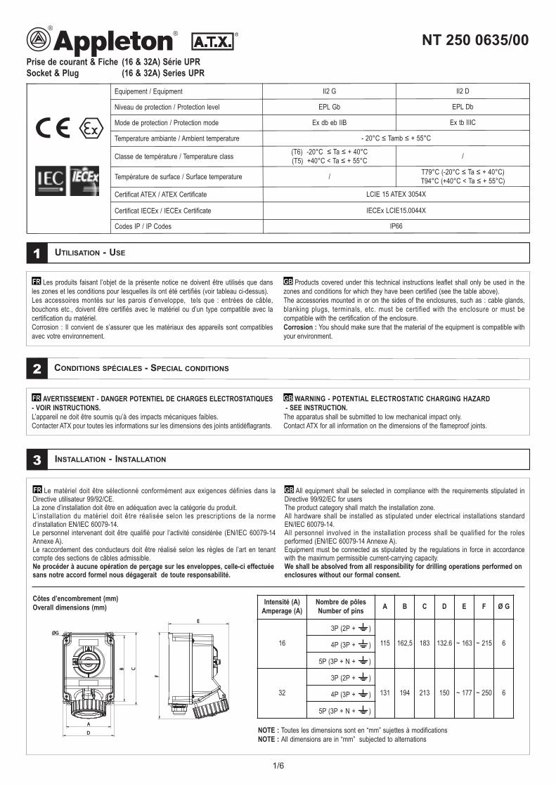
1/6 Prise de courant & Fiche (16 & 32A) Série UPR Socket & Plug (16 & 32A) Series UPR NT 250 0635/00 Equipement / Equipment II2 G II2 D Niveau de protection / Protection level EPL Gb EPL Db Mode de protection / Protection mode Ex db eb IIB Ex tb IIIC Temperature ambiante / Ambient temperature - 20°C ≤ Tamb ≤ + 55°C Classe de température / Temperature class (T6) -20°C ≤ Ta ≤ + 40°C (T5) +40°C < Ta ≤ + 55°C / Température de surface / Surface temperature / T79°C (-20°C ≤ Ta ≤ + 40°C) T94°C (+40°C < Ta ≤ + 55°C) Certificat ATEX / ATEX Certificate LCIE 15 ATEX 3054X Certificat IECEx / IECEx Certificate IECEx LCIE15.0044X Codes IP / IP Codes IP66 UTILISATION - USE 1 Les produits faisant l’objet de la présente notice ne doivent être utilisés que dans les zones et les conditions pour lesquelles ils ont été certifiés (voir tableau ci-dessus). Les accessoires montés sur les parois d’enveloppe, tels que : entrées de câble, bouchons etc., doivent être certifiés avec le matériel ou d’un type compatible avec la certification du matériel. Corrosion : Il convient de s’assurer que les matériaux des appareils sont compatibles avec votre environnement. FR Products covered under this technical instructions leaflet shall only be used in the zones and conditions for which they have been certified (see the table above). The accessories mounted in or on the sides of the enclosures, such as : cable glands, blanking plugs, terminals, etc. must be certified with the enclosure or must be compatible with the certification of the enclosure. Corrosion : You should make sure that the material of the equipment is compatible with your environment. GB CONDITIONS SPÉCIALES - SPECIAL CONDITIONS 2 INSTALLATION - INSTALLATION 3 Le matériel doit être sélectionné conformément aux exigences définies dans la Directive utilisateur 99/92/CE. La zone d’installation doit être en adéquation avec la catégorie du produit. L’installation du matériel doit être réalisée selon les prescriptions de la norme d’installation EN/IEC 60079-14. Le personnel intervenant doit être qualifié pour l’activité considérée (EN/IEC 60079-14 Annexe A). Le raccordement des conducteurs doit être réalisé selon les règles de l’art en tenant compte des sections de câbles admissible. Ne procéder à aucune opération de perçage sur les enveloppes, celle-ci effectuée sans notre accord formel nous dégagerait de toute responsabilité. FR All equipment shall be selected in compliance with the requirements stipulated in Directive 99/92/EC for users The product category shall match the installation zone. All hardware shall be installed as stipulated under electrical installations standard EN/IEC 60079-14. All personnel involved in the installation process shall be qualified for the roles performed (EN/IEC 60079-14 Annexe A). Equipment must be connected as stipulated by the regulations in force in accordance with the maximum permissible current-carrying capacity. We shall be absolved from all responsibility for drilling operations performed on enclosures without our formal consent. GB D A B C ØG ØG E F Intensité (A) Amperage (A) Nombre de pôles Number of pins A B C D E F Ø G 16 3P (2P + ) 115 162,5 183 132.6 ~ 163 ~ 215 6 4P (3P + ) 5P (3P + N + ) 32 3P (2P + ) 131 194 213 150 ~ 177 ~ 250 6 4P (3P + ) 5P (3P + N + ) Côtes d’encombrement (mm) Overall dimensions (mm) NOTE : Toutes les dimensions sont en “mm” sujettes à modifications NOTE : All dimensions are in “mm” subjected to alternations AVERTISSEMENT - DANGER POTENTIEL DE CHARGES ELECTROSTATIQUES - VOIR INSTRUCTIONS. L’appareil ne doit être soumis qu’à des impacts mécaniques faibles. Contacter ATX pour toutes les informations sur les dimensions des joints antidéflagrants. FR WARNING - POTENTIAL ELECTROSTATIC CHARGING HAZARD - SEE INSTRUCTION. The apparatus shall be submitted to low mechanical impact only. Contact ATX for all information on the dimensions of the flameproof joints. GB
Transcript of Appleton UPR Series Plugs and Sockets Instruction Sheet · PDF fileseal (OS) to match the...
1/6
Prise de courant & Fiche (16 & 32A) Série UPRSocket & Plug (16 & 32A) Series UPR
NT 250 0635/00
Equipement / Equipment II2 G II2 D
Niveau de protection / Protection level EPL Gb EPL Db
Mode de protection / Protection mode Ex db eb IIB Ex tb IIIC
Temperature ambiante / Ambient temperature - 20°C ≤ Tamb ≤ + 55°C
Classe de température / Temperature class (T6) -20°C ≤ Ta ≤ + 40°C (T5) +40°C < Ta ≤ + 55°C /
Température de surface / Surface temperature / T79°C (-20°C ≤ Ta ≤ + 40°C) T94°C (+40°C < Ta ≤ + 55°C)
Certificat ATEX / ATEX Certificate LCIE 15 ATEX 3054X
Certificat IECEx / IECEx Certificate IECEx LCIE15.0044X
Codes IP / IP Codes IP66
UTILISATION - USE1
Les produits faisant l’objet de la présente notice ne doivent être utilisés que dansles zones et les conditions pour lesquelles ils ont été certifiés (voir tableau ci-dessus).Les accessoires montés sur les parois d’enveloppe, tels que : entrées de câble, bouchons etc., doivent être certifiés avec le matériel ou d’un type compatible avec la certification du matériel.Corrosion : Il convient de s’assurer que les matériaux des appareils sont compatiblesavec votre environnement.
FR Products covered under this technical instructions leaflet shall only be used in thezones and conditions for which they have been certified (see the table above).The accessories mounted in or on the sides of the enclosures, such as : cable glands,blanking plugs, terminals, etc. must be certified with the enclosure or must becompatible with the certification of the enclosure. Corrosion : You should make sure that the material of the equipment is compatible withyour environment.
GB
CONDITIONS SPÉCIALES - SPECIAL CONDITIONS2
INSTALLATION - INSTALLATION3
Le matériel doit être sélectionné conformément aux exigences définies dans laDirective utilisateur 99/92/CE.La zone d’installation doit être en adéquation avec la catégorie du produit.L’installation du matériel doit être réalisée selon les prescriptions de la normed’installation EN/IEC 60079-14.Le personnel intervenant doit être qualifié pour l’activité considérée (EN/IEC 60079-14Annexe A).Le raccordement des conducteurs doit être réalisé selon les règles de l’art en tenantcompte des sections de câbles admissible.Ne procéder à aucune opération de perçage sur les enveloppes, celle-ci effectuéesans notre accord formel nous dégagerait de toute responsabilité.
FR All equipment shall be selected in compliance with the requirements stipulated in Directive 99/92/EC for users The product category shall match the installation zone.All hardware shall be installed as stipulated under electrical installations standardEN/IEC 60079-14.All personnel involved in the installation process shall be qualified for the rolesperformed (EN/IEC 60079-14 Annexe A).Equipment must be connected as stipulated by the regulations in force in accordancewith the maximum permissible current-carrying capacity.We shall be absolved from all responsibility for drilling operations performed onenclosures without our formal consent.
GB
DD
AA
BB CC
ØGØG
EE
FF
Intensité (A)Amperage (A)
Nombre de pôlesNumber of pins A B C D E F Ø G
16
3P (2P + )
115 162,5 183 132.6 ~ 163 ~ 215 64P (3P + )
5P (3P + N + )
32
3P (2P + )
131 194 213 150 ~ 177 ~ 250 64P (3P + )
5P (3P + N + )
Côtes d’encombrement (mm)Overall dimensions (mm)
NOTE : Toutes les dimensions sont en “mm” sujettes à modificationsNOTE : All dimensions are in “mm” subjected to alternations
AVERTISSEMENT - DANGER POTENTIEL DE CHARGES ELECTROSTATIQUES- VOIR INSTRUCTIONS.L’appareil ne doit être soumis qu’à des impacts mécaniques faibles.Contacter ATX pour toutes les informations sur les dimensions des joints antidéflagrants.
FR WARNING - POTENTIAL ELECTROSTATIC CHARGING HAZARD- SEE INSTRUCTION.
The apparatus shall be submitted to low mechanical impact only.Contact ATX for all information on the dimensions of the flameproof joints.
GB
2/6
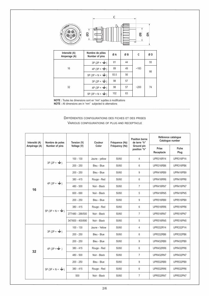
Intensité (A)Ampérage (A)
Nombre de polesNumber of pins
Tension (V)Voltage (V)
CouleurColor
Fréquence (Hz)Fréquency (Hz)
Position borne de terre “h”Ground pinposition “h”
Référence catalogue Catalogue number
Prise Receptacle
FichePlug
16
3P (2P + )100 - 130 Jaune - yellow 50/60 4 UPR316RY4 UPR316PY4
200 - 250 Bleu - Blue 50/60 6 UPR316RB6 UPR316PB6
4P (3P + )
200 - 250 Bleu - Blue 50/60 9 UPR416RB9 UPR416PB9
380 - 415 Rouge - Red 50/60 6 UPR416RR6 UPR416PR6
480 - 500 Noir - Black 50/60 7 UPR416RN7 UPR416PN7
600 - 690 Noir - Black 50/60 5 UPR416RN5 UPR416PN5
5P (3P + N + )
200 - 250 Bleu - Blue 50/60 9 UPR516RB9 UPR516PB9
380 - 415 Rouge - Red 50/60 6 UPR516RR6 UPR516PR6
277/480 - 288/500 Noir - Black 50/60 7 UPR516RN7 UPR516PN7
347/600 - 400/690 Noir - Black 50/60 5 UPR516RN5 UPR516PN5
32
3P (2P + )100 - 130 Jaune - Yellow 50/60 4 UPR332RY4 UPR332PY4
200 - 250 Bleu - Blue 50/60 6 UPR332RB6 UPR332PB6
4P (3P + )
200 - 250 Bleu - Blue 50/60 9 UPR432RB9 UPR432PB9
380 - 415 Rouge - Red 50/60 6 UPR432RR6 UPR432PR6
480 - 500 Noir - Black 50/60 7 UPR432RN7 UPR432PN7
5P (3P + N + )
200 - 250 Bleu - Blue 50/60 9 UPR532RB9 UPR532PB9
380 - 415 Rouge - Red 50/60 6 UPR532RR6 UPR532PR6
500 Noir - Black 50/60 7 UPR532RN7 UPR532PN7
ØD
ØD
CC
ØB
ØB
ØA
ØA
Intensité (A)Amperage (A)
Nombre de pôlesNumber of pins Ø A Ø B C Ø D
16
3P (2P + ) 81 44
~183
55
4P (3P + ) 89 4966
5P (3P + N + ) 93.5 56
32
3P (2P + ) 98 57
~200 744P (3P + ) 98 57
5P (3P + N + ) 102 63
NOTE : Toutes les dimensions sont en “mm” sujettes à modificationsNOTE : All dimensions are in “mm” subjected to alternations
DIFFÉRENTES CONFIGURATIONS DES FICHES ET DES PRISESVARIOUS CONFIGURATIONS OF PLUG AND RECEPTACLE
3/6
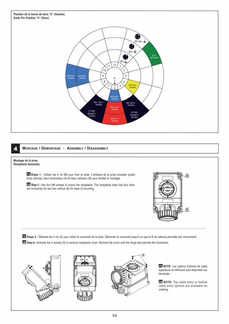
Position de la borne de terre “h” (Horaire)Earth Pin Position “h” (Hour)
MONTAGE / DÉMONTAGE - ASSEMBLY / DISASSEMBLY4
Etape 1 : Utiliser les 4 vis M6 pour fixer la prise. L'embase de la prise possède quatretrous oblongs; deux horizontaux (A) et deux verticaux (B) pour faciliter le montage.
Step-1: Use four M6 screws to mount the receptacle. The receptacle base has four slots-two horizontal (A) and two vertical (B) for ease of mounting.
FR
GB
Etape 2 : Dévisser les 4 vis (S) pour retirer le couvercle de la prise. Démonter le couvercle jusqu’à ce que le fil de retenue permette son mouvement.
Step-2: Unscrew the 4 screws (S) to remove receptacle cover. Remove the cover until the hinge wire permits the movement.
FR
GB
Montage de la prise Receptacle Assembly
AA
BB
NOTE: Les options d’entrée de cablesupérieure et inférieure sont disponible surdemande.
NOTE: Top cable entry or bottomcable entry options are available forordering
FR
GB
SS
4/6
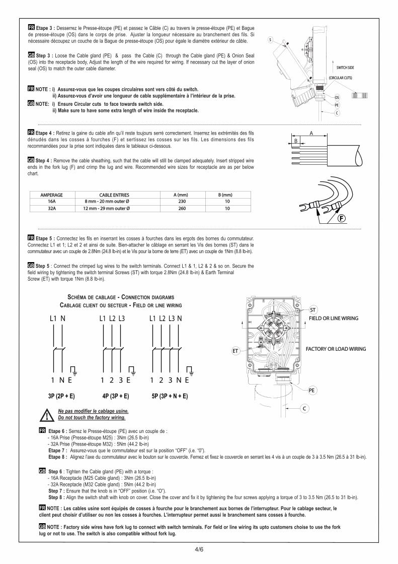
Etape 3 : Desserrez le Presse-étoupe (PE) et passez le Câble (C) au travers le presse-étoupe (PE) et Baguede presse-étoupe (OS) dans le corps de prise. Ajuster la longueur nécessaire au branchement des fils. Sinécessaire découpez un couche de la Bague de presse-étoupe (OS) pour égale le diamètre extérieur de câble.
Step 3 : Loose the Cable gland (PE) & pass the Cable (C) through the Cable gland (PE) & Onion Seal(OS) into the receptacle body, Adjust the length of the wire required for wiring. If necessary cut the layer of onionseal (OS) to match the outer cable diameter.
FR
GB
NOTE : i) Assurez-vous que les coupes circulaires sont vers côté du switch.ii) Assurez-vous d’avoir une longueur de cable supplémentaire à l’intérieur de la prise.
NOTE: i) Ensure Circular cuts to face towards switch side. ii) Make sure to have some extra length of wire inside the receptacle.
FR
GB
Etape 4 : Retirez la gaine du cable afin qu’il reste toujours serré correctement. Inserrez les extrémités des filsdénudés dans les cosses à fourches (F) et sertissez les cosses sur les fils. Les dimensions des filsrecommandées pour la prise sont indiquées dans le tableaux ci-dessous.
Step 4 : Remove the cable sheathing, such that the cable will still be clamped adequately. Insert stripped wireends in the fork lug (F) and crimp the lug and wire. Recommended wire sizes for receptacle are as per belowchart.
FR
GB
F
Etape 5 : Connectez les fils en inserrant les cosses à fourches dans les ergots des bornes du commutateur.Connectez L1 et 1; L2 et 2 et ainsi de suite. Bien-attacher le câblage en serrant les Vis des bornes (ST) dans lecommutateur avec un couple de 2.8Nm (24.8 lb-in) et le Vis pour la borne de terre (ET) avec un couple de 1Nm (8.8 lb-in).
Step 5 : Connect the crimped lug wires to the switch terminals. Connect L1 & 1, L2 & 2 & so on. Secure thefield wiring by tightening the switch terminal Screws (ST) with torque 2.8Nm (24.8 lb-in) & Earth TerminalScrew (ET) with torque 1Nm (8.8 lb-in).
FR
GB
Etape 6 : Serrez le Presse-étoupe (PE) avec un couple de :- 16A Prise (Presse-étoupe M25) : 3Nm (26.5 lb-in)- 32A Prise (Presse-étoupe M32) : 5Nm (44.2 lb-in)Etape 7 : Assurez-vous que le commutateur est sur la position “OFF” (i.e. “0”).Etape 8 : Alignez l’axe du commutateur avec le bouton sur le couvercle. Fernez et fixez le couvercle en serrant les 4 vis à un couple de 3 à 3.5 Nm (26.5 à 31 lb-in).
Step 6 : Tighten the Cable gland (PE) with a torque :- 16A Receptacle (M25 Cable gland) : 3Nm (26.5 lb-in)- 32A Receptacle (M32 Cable gland) : 5Nm (44.2 lb-in)Step 7 : Ensure that the knob is in “OFF” position (i.e. “O”).Step 8 : Align the switch shaft with knob on cover. Close the cover and fix it by tightening the four screws applying a torque of 3 to 3.5 Nm (26.5 to 31 lb-in).
FR
GB
L1 N
N E1
3P (2P + E)
L1 L2 L3
1 2 3 E
4P (3P + E) 5P (3P + N + E)
N E1 2 3
NL1 L2 L3
SCHÉMA DE CABLAGE - CONNECTION DIAGRAMSCABLAGE CLIENT OU SECTEUR - FIELD OR LINE WIRING
CC
STST
ETET
FIELD OR LINE WIRINGFIELD OR LINE WIRING
FACTORY OR LOAD WIRINGFACTORY OR LOAD WIRING
PEPE
NOTE : Les cables usine sont équipés de cosses à fourche pour le branchement aux bornes de l’interrupteur. Pour le cablage secteur, leclient peut choisir d’utiliser ou non les cosses à fourches. L’interrupteur permet aussi le branchement sans cosses à fourche.
NOTE : Factory side wires have fork lug to connect with switch terminals. For field or line wiring its upto customers choise to use the forklug or not to use. The switch is also compatible without fork lug.
FR
GB
AB
Ne pas modifier le cablage usine.Do not touch the factory wiring.
AMPERAGEAMPERAGE CABLE ENTRIESCABLE ENTRIES A (mm)A (mm) B (mm)B (mm)16A 16A 8 mm - 20 mm outer Ø8 mm - 20 mm outer Ø 230230 1010
32A32A 12 mm - 29 mm outer Ø12 mm - 29 mm outer Ø 260260 1010
OSOS
PEPE
CC
(CIRCULAR CUTS)(CIRCULAR CUTS)
SWITCH SIDESWITCH SIDE
SS
5/6
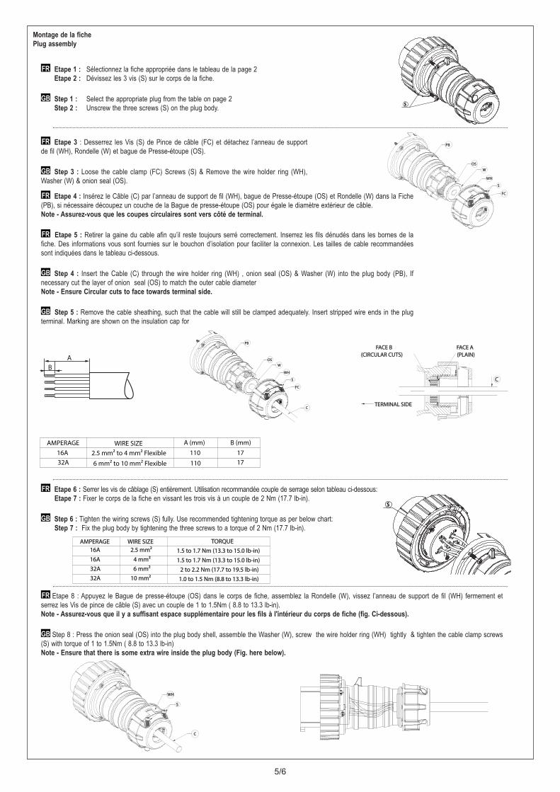
Etape 1 : Sélectionnez la fiche appropriée dans le tableau de la page 2Etape 2 : Dévissez les 3 vis (S) sur le corps de la fiche.
Step 1 : Select the appropriate plug from the table on page 2Step 2 : Unscrew the three screws (S) on the plug body.
FR
GB
Etape 3 : Desserrez les Vis (S) de Pince de câble (FC) et détachez l’anneau de supportde fil (WH), Rondelle (W) et bague de Presse-étoupe (OS).
Step 3 : Loose the cable clamp (FC) Screws (S) & Remove the wire holder ring (WH),Washer (W) & onion seal (OS).
FR
GB
Montage de la fichePlug assembly
SS
WHWH
SS
OSOSWW
PBPB
FCFC
SS
Etape 6 : Serrer les vis de câblage (S) entièrement. Utilisation recommandée couple de serrage selon tableau ci-dessous:Etape 7 : Fixer le corps de la fiche en vissant les trois vis à un couple de 2 Nm (17.7 lb-in).
Step 6 : Tighten the wiring screws (S) fully. Use recommended tightening torque as per below chart: Step 7 : Fix the plug body by tightening the three screws to a torque of 2 Nm (17.7 lb-in).
FR
GB
Etape 8 : Appuyez le Bague de presse-étoupe (OS) dans le corps de fiche, assemblez la Rondelle (W), vissez l’anneau de support de fil (WH) fermement etserrez les Vis de pince de câble (S) avec un couple de 1 to 1.5Nm ( 8.8 to 13.3 lb-in).Note - Assurez-vous que il y a suffisant espace supplémentaire pour les fils à l'intérieur du corps de fiche (fig. Ci-dessous).
Step 8 : Press the onion seal (OS) into the plug body shell, assemble the Washer (W), screw the wire holder ring (WH) tightly & tighten the cable clamp screws(S) with torque of 1 to 1.5Nm ( 8.8 to 13.3 lb-in)Note - Ensure that there is some extra wire inside the plug body (Fig. here below).
FR
GB
AB
Etape 4 : Insérez le Câble (C) par l’anneau de support de fil (WH), bague de Presse-étoupe (OS) et Rondelle (W) dans la Fiche(PB), si nécessaire découpez un couche de la Bague de presse-étoupe (OS) pour égale le diamètre extérieur de câble.Note - Assurez-vous que les coupes circulaires sont vers côté de terminal.
Etape 5 : Retirer la gaine du cable afin qu’il reste toujours serré correctement. Inserrez les fils dénudés dans les bornes de lafiche. Des informations vous sont fournies sur le bouchon d’isolation pour faciliter la connexion. Les tailles de cable recommandéessont indiquées dans le tableau ci-dessous.
Step 4 : Insert the Cable (C) through the wire holder ring (WH) , onion seal (OS) & Washer (W) into the plug body (PB), Ifnecessary cut the layer of onion seal (OS) to match the outer cable diameter Note - Ensure Circular cuts to face towards terminal side.
Step 5 : Remove the cable sheathing, such that the cable will still be clamped adequately. Insert stripped wire ends in the plugterminal. Marking are shown on the insulation cap for
FR
GB
FR
GB
AMPERAGE WIRE SIZE A (mm) B (mm)16A 2.5 mm² to 4 mm² Flexible 110 1732A 6 mm² to 10 mm² Flexible 110 17
WHWH
OSOS
PBPB
CC
SS
WW
FCFC
CC
FACE AFACE A(PLAIN)(PLAIN)
FACE BFACE B(CIRCULAR CUTS)(CIRCULAR CUTS)
TERMINAL SIDETERMINAL SIDE
AMPERAGEAMPERAGE WIRE SIZEWIRE SIZE TORQUE TORQUE 16A16A 2.5 mm²2.5 mm² 1.5 to 1.7 Nm (13.3 to 15.0 lb-in)1.5 to 1.7 Nm (13.3 to 15.0 lb-in)16A16A 4 mm²4 mm² 1.5 to 1.7 Nm (13.3 to 15.0 lb-in)1.5 to 1.7 Nm (13.3 to 15.0 lb-in)32A32A 6 mm²6 mm² 2 to 2.2 Nm (17.7 to 19.5 lb-in)2 to 2.2 Nm (17.7 to 19.5 lb-in)32A32A 10 mm²10 mm² 1.0 to 1.5 Nm (8.8 to 13.3 lb-in)1.0 to 1.5 Nm (8.8 to 13.3 lb-in)
WHWH
SS
CC
6/6
MISE EN SERVICE - PUTTING INTO SERVICE5
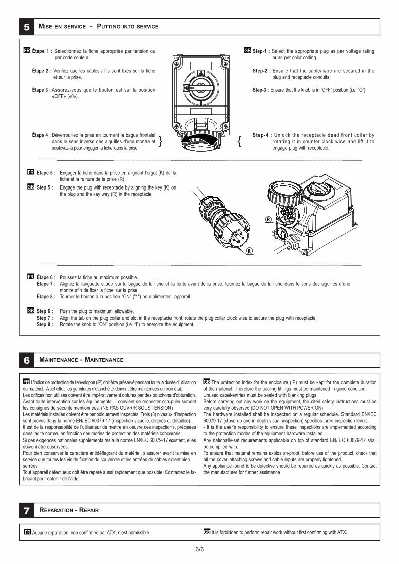
Étape 1 : Sélectionnez la fiche appropriée par tension ou par code couleur.
Étape 2 : Vérifiez que les câbles / fils sont fixés sur la fiche et sur la prise.
Étape 3 : Assurez-vous que le bouton est sur la position «OFF» («0»).
Étape 4 : Déverrouillez la prise en tournant la bague frontalel dans le sens inverse des aiguilles d'une montre et soulevez-la pour engager la fiche dans la prise
FR Step-1 : Select the appropriate plug as per voltage rating or as per color coding.
Step-2 : Ensure that the cable/ wire are secured in the plug and receptacle conduits.
Step-3 : Ensure that the knob is in “OFF” position (i.e. “O”).
Step-4 : Unlock the receptacle dead front col lar by rotating it in counter clock wise and l ift i t to engage plug with receptacle.
GB
Etape 5 : Engager la fiche dans la prise en alignant l’ergot (K) de la fiche et la rainure de la prise (R)
Step 5 : Engage the plug with receptacle by aligning the key (K) on the plug and the key way (R) in the receptacle.
FR
GB
Étape 6 : Poussez la fiche au maximum possible..Étape 7 : Alignez la languette située sur la bague de la fiche et la fente avant de la prise, tournez la bague de la fiche dans le sens des aiguilles d’une
montre afin de fixer la fiche sur la priseÉtape 8 : Tourner le bouton à la position "ON" ("1") pour alimenter l'appareil.
Step 6 : Push the plug to maximum allowable. Step 7 : Align the tab on the plug collar and slot in the receptacle front, rotate the plug collar clock wise to secure the plug with receptacle.Step 8 : Rotate the knob to “ON” position (i.e. “I”) to energize the equipment.
FR
GB
KK
RR
MAINTENANCE - MAINTENANCE6
L'indice de protection de l'enveloppe (IP) doit être préservé pendant toute la durée d’utilisationdu matériel. A cet effet, les garnitures d'étanchéité doivent être maintenues en bon état.Les orifices non utilisés doivent être impérativement obturés par des bouchons d'obturation.Avant toute intervention sur les équipements, il convient de respecter scrupuleusementles consignes de sécurité mentionnées. (NE PAS OUVRIR SOUS TENSION)Les matériels installés doivent être périodiquement inspectés. Trois (3) niveaux d’inspectionsont prévus dans la norme EN/IEC 60079-17 (inspection visuelle, de près et détaillée).Il est de la responsabilité de l’utilisateur de mettre en oeuvre ces inspections, préciséesdans ladite norme, en fonction des modes de protection des matériels concernés.Si des exigences nationales supplémentaires à la norme EN/IEC 60079-17 existent, ellesdoivent être observées.Pour bien conserver le caractère antidéflagrant du matériel, s’assurer avant la mise enservice que toutes les vis de fixation du couvercle et les entrées de câbles soient bienserrées.Tout appareil défectueux doit être réparé aussi rapidement que possible. Contactez le fa-bricant pour obtenir de l’aide.
FR The protection index for the enclosure (IP) must be kept for the complete durationof the material. Therefore the sealing fittings must be maintened in good condition.Unused cabel-entries must be sealed with blanking plugs.Before carrying out any work on the equipment, the cited safety instructions must bevery carefully observed (DO NOT OPEN WITH POWER ON)The hardware installed shall be inspected on a regular schedule. Standard EN/IEC60079-17 (close-up and in-depth visual inspection) specifies three inspection levels.- It is the user's responsibility to ensure these inspections are implemented accordingto the protection modes of the equipment hardware installed.Any nationally-set requirements applicable on top of standard EN/IEC 60079-17 shallbe complied with.To ensure that material remains explosion-proof, before use of the product, check thatall the cover attaching screws and cable inputs are properly tightened.Any appliance found to be defective should be repaired as quickly as possible. Contactthe manufacturer for further assistance
GB
RÉPARATION - REPAIR7
Aucune réparation, non confirmée par ATX, n’est admissible. It is forbidden to perform repair work without first confirming with ATX.FR GB
{}