Active annular-beam laser autocollimator system
6
Active annular-beam laser autocollimator system P. R. Yoder, Jr., E. R. Schlesinger, and J. L. Chickvary An autocollimator using an axicon and a beam expander telescope to generate a 12.5-cm. o.d. annular beam of helium-neon laser light with high (25:1) diameter-to-width ratio has been developed. It is used with a two-axis, electromagnetically actuated mirror assembly to acquire automatically and maintain dynamically autocollimation from a nearby but separately mounted annular mirror. The servo system controls beam alignment even though angular vibratory motions of the annular mirror make it appear to tilt relative to the autocollimator as much as 7 mrad at frequencies below 300 Hz. This paper describes the optical sys- tem and the alignment sensing and control system. Introduction In this paper, we describe a special-purpose, elec- trooptical autocollimator system (see Fig. 1) that projects a collimated He-Ne laser beam onto a mirror attached rigidly to a remote equipment assembly, measures the alignment error between the transmit- ted and received beams, and automatically (i.e., with- out human intervention) corrects this error by ad- justing the pointing of the beam so it always is nor- mal to the remote mirror surface within a small frac- tion of a milliradian. This beam alignment is main- tained even though the assembly to which the remote mirror is attached is vibrating angularly due to bend- ing of the intervening mechanical structure with an- gular amplitudes as large as 7 mrad and at frequen- cies as high as 200 Hz. Steering of the beam is ac- complished by a servocontrolled, two-axis dynamic mirror located between the autocollimator and the remote mirror. The autocollimator and the dynamic mirror are both mounted on a semirigid table. The beam direction after reflection from the dynamic mirror is required by the application to be vertical, while the separation between the autocollimator and the remote equipment is set at approximately 3.7 m. The shaded beam shown in Fig. 1 passing through the autocollimator, reflecting from the dynamic mir- ror, and entering the remote equipment assembly represents an auxiliary optical beam as large as 10 cm in diameter. The main purpose of the equipment described here is to keep this auxiliary beam in prop- er angular alignment relative to the remote equip- ment. This is done indirectly by initially boresight- The authors are with the Electro-Optical Division, Perkin- Elmer Corporation, Norwalk, Connecticut 06856. Received 21 October 1974. ing the annular reference beam (shown as dashed lines emanating from and returning to the autocolli- mator) to the auxiliary beam and then controlling the alignment of the reference beam. Long-term stabili- ty of the system is required to be <0.1 mrad in the se- vere thermal, acoustic, and vibration environments typical of aerospace applications. This forced the mechanical design to employ thermal compensation, rugged structures, and high stiffness materials. The significant challenge met by this equipment is in the design of an automatic alignment system with a servocontrolled, optical element (mirror) having adequately fast response to correct >200-Hz align- ment errors and having the required clear aperture for reflection of the 10-cm diam auxiliary beam at a 520 angle of incidence. A tolerance on peak-to-peak geometrical distortion induced into the dynamic mir- ror surface when driven at maximum torque was set at /20 for X = 0.63 ,um in order to provide adequate optical quality. Detailed analysis of the optome- chanical system was required during the design to in- sure that the system would provide the required dy- namic response and optical performance. No means of accomplishing this has previously been reported. Optical Subsystem Description Figure 2 shows the autocollimator optical system in simplified schematic form. The functions of the components in the sequence encountered by the He-Ne laser beam will now be described. Immediately upon exiting the laser, the beam is fo- cused to a point image and then recollimated by con- focal air-spaced doublets acting as a simple telescope. A motor driven slotted disk passing through the in- termediate focus intensity modulates the beam at a 20-KHz frequency to allow ac signal processing in the sensor electronics. 1890 APPLIED OPTICS / Vol. 14, No. 8 / August 1975
Transcript of Active annular-beam laser autocollimator system
Active annular-beam laser autocollimator system
P. R. Yoder, Jr., E. R. Schlesinger, and J. L. Chickvary
An autocollimator using an axicon and a beam expander telescope to generate a 12.5-cm. o.d. annular beamof helium-neon laser light with high (25:1) diameter-to-width ratio has been developed. It is used with atwo-axis, electromagnetically actuated mirror assembly to acquire automatically and maintain dynamicallyautocollimation from a nearby but separately mounted annular mirror. The servo system controls beamalignment even though angular vibratory motions of the annular mirror make it appear to tilt relative tothe autocollimator as much as 7 mrad at frequencies below 300 Hz. This paper describes the optical sys-tem and the alignment sensing and control system.
IntroductionIn this paper, we describe a special-purpose, elec-
trooptical autocollimator system (see Fig. 1) thatprojects a collimated He-Ne laser beam onto a mirrorattached rigidly to a remote equipment assembly,measures the alignment error between the transmit-ted and received beams, and automatically (i.e., with-out human intervention) corrects this error by ad-justing the pointing of the beam so it always is nor-mal to the remote mirror surface within a small frac-tion of a milliradian. This beam alignment is main-tained even though the assembly to which the remotemirror is attached is vibrating angularly due to bend-ing of the intervening mechanical structure with an-gular amplitudes as large as 7 mrad and at frequen-cies as high as 200 Hz. Steering of the beam is ac-complished by a servocontrolled, two-axis dynamicmirror located between the autocollimator and theremote mirror. The autocollimator and the dynamicmirror are both mounted on a semirigid table. Thebeam direction after reflection from the dynamicmirror is required by the application to be vertical,while the separation between the autocollimator andthe remote equipment is set at approximately 3.7 m.
The shaded beam shown in Fig. 1 passing throughthe autocollimator, reflecting from the dynamic mir-ror, and entering the remote equipment assemblyrepresents an auxiliary optical beam as large as 10 cmin diameter. The main purpose of the equipmentdescribed here is to keep this auxiliary beam in prop-er angular alignment relative to the remote equip-ment. This is done indirectly by initially boresight-
The authors are with the Electro-Optical Division, Perkin-Elmer Corporation, Norwalk, Connecticut 06856.
Received 21 October 1974.
ing the annular reference beam (shown as dashedlines emanating from and returning to the autocolli-mator) to the auxiliary beam and then controlling thealignment of the reference beam. Long-term stabili-ty of the system is required to be <0.1 mrad in the se-vere thermal, acoustic, and vibration environmentstypical of aerospace applications. This forced themechanical design to employ thermal compensation,rugged structures, and high stiffness materials.
The significant challenge met by this equipment isin the design of an automatic alignment system witha servocontrolled, optical element (mirror) havingadequately fast response to correct >200-Hz align-ment errors and having the required clear aperturefor reflection of the 10-cm diam auxiliary beam at a520 angle of incidence. A tolerance on peak-to-peakgeometrical distortion induced into the dynamic mir-ror surface when driven at maximum torque was setat /20 for X = 0.63 ,um in order to provide adequateoptical quality. Detailed analysis of the optome-chanical system was required during the design to in-sure that the system would provide the required dy-namic response and optical performance. No meansof accomplishing this has previously been reported.
Optical Subsystem DescriptionFigure 2 shows the autocollimator optical system
in simplified schematic form. The functions of thecomponents in the sequence encountered by theHe-Ne laser beam will now be described.
Immediately upon exiting the laser, the beam is fo-cused to a point image and then recollimated by con-focal air-spaced doublets acting as a simple telescope.A motor driven slotted disk passing through the in-termediate focus intensity modulates the beam at a20-KHz frequency to allow ac signal processing in thesensor electronics.
1890 APPLIED OPTICS / Vol. 14, No. 8 / August 1975

MIRROR DRIVE SIGNALS Returning again to Fig. 2, we see that this perforat-| MIRROR POSITION SGNALS ^ ed folding mirror sends the annular beam through a
INPUT POWER EL C-TOI beam splitting prism into a 5-power beam expandingOUTPUT SIGNALS E I REMOTE telescope comprising two confocal f/2 air-spaced dou-
He~ ANGLE ASSEMBLY blets. This telescope scales up the beam to 12.5-cmSENSOR I o.d. The annular beam width increases to about 0.5
AUTOCOLLIMATOR L= r- ID-a "cm. The diameter-to-width aspect ratio of the ex-ASSEMBLY , | BEAM l ANNULA~ EA ANa panded annulus so produced is 25:1. The expanded
TELESCOPE I MIRROR + 2 ) beam reflects from an annular beam combining mir-
AUXILIAR - ror to the dynamic mirror and proceeds to the auto-OPTICA L13EAtMA- collimating reference mirror attached to the remote
T 7 , DYN 3 TWO-AXIS equipment. The latter mirror also is annular in con-/ / MIRROR figuration. The 10-cm diam auxiliary optical beam
BEAM COMBINING MIRROR ANNULAR BEAM ASSEMBY .is shown passing through the hole in the reference
Fig. 1. Functional block diagram of autocollimator system. mirror into the remote equipment assembly.
COARSE DETECTORFINE DETECTOR ,4
/oc. RELAY LENS 44 BEAM SPLITTING PLATE10 cm _Ha- C INPU T I-- -I--- T'AIO
AUXILIARY g o -= IiIIAXICONBEAM Ll II
(jr) g OBJECTIVE LENSE I 'W g 1 -BEAM SPLITTING PRISM II 1
mC OMB I N 1 - - - _.:r
ORROR 1/l / _1; _ _ =_PARATON COPPER Fig. 2. Simplified optical schematic.
1 i i 1 t: 5X BEAM EXPANDING PLATES '5 /DEMOoTELESCOPE MO~~~~DO
\ ago]~~J 12.5 cm
ANNULAR REFERENCE..." X . 7,,. MIRROR ON REMOTE I R
EUIPMENT ASSEMBLYA
The beam next falls upon the conical nose of a -
glass axicon' that turns the input laser beam into an i
annulus with an o.d. of 24.4 mm. Figure 3 shows thisaxicon and a penny for size comparison. From the R
sketch at the top of this figure, it may be noted that aray at the outside of the input beam is transferred to T RA PAT
the inside of the output annulus and that the annularTRHbeam width equals the radius of the input beam. Es-sentially all the energy of the beam inputted to the 3 Caxicon is remapped into the annulus so, photometri-cally, this is a highly efficient means of generatingsuch an output beam. The width of the annulus isdetermined by the diameter of the input laser beamand the axicon design (length, apex angle, and mate-rial). The particular annulus diameter to width ratio used was chosen to facilitate separation of the outputbeam from the input beam with the perforated mir-ror located in front of the axicon. Fig. 3. Configuration of folded refraction axicon.
August 1975 / Vol. 14, No. 8 / APPLIED OPTICS 1891

The annular beam autocollimated from the refer-ence mirror returns to and passes through the beamexpander telescope and is reflected by the beamsplitter prism's internal surface into a four-elementobjective lens. This lens forms a point image at itsfocal plane on a dual-axis, continuous-position-sens-ing silicon detector that provides two electrical out-put signals proportional to the displacements of theimage spot from orthogonal axes centered on the13.5-mm diam sensitive surface. The nominal focallength of the optics that focus the autocollimatedbeam on this detector is 330 mm so the image tran-slates 0.66 mm/mrad of reference mirror tilt. Imagemotions corresponding to the system acquisition fieldof view of L17 mrad are measured by this sensor so itis called the coarse angle sensor.
The thin beam splitter plate located in front of thecoarse sensor focus reflects a portion of the converg-ing beam into a 16-power microscope objective lensthat relays the image onto a second detector similarto the first. Since the system focal length is in-creased substantially by this relay lens to nearly 5.3m, this detector acts as a fine angle sensor producingan image translation of about 0.01 mm/,grad of refer-ence mirror tilt. Because of the action of the beamsplitter plate, the +O.1-mrad fine sensor field is su-perimposed upon and centered with that of thecoarse sensor. The electronics system is arranged sothat the coarse sensor's signals are ignored when thefine sensor receives light. Whenever the autocolli-mated beam inclination is within the acquisitionrange of the system, one or the other of the two de-tectors provides orthogonal error signals that can beused to drive the beam toward the null condition.The electronic system is designed so that rapidlyswitching control from coarse to fine, or vice versa,does not introduce step signal disturbances thatwould cause the servo system to oscillate.
A high degree of aberrational correction of thealignment system optics was needed only within thesmall field of view of the fine sensor and for the zonalapertures actually encountered by the transmittedand received annular beams. The lenses in the 5-power beam expander telescope were therefore de-signed at f/2 while the objective lens works at f/2.7.Schott SK-16 and SF-18 glasses were used exclusive-ly in these lenses, and aspherical surfaces were notrequired.
The beam splitting prism used here is a special de-sign that functions at high efficiency with properlyoriented plane-polarized monochromatic collimatedlight beams such as come from a laser. The He-Netype laser was chosen for its reliability and visibility.The plane of polarization of the outbound laser beamis parallel to the plane of reflection of the beam split-ter surface and so is transmitted with essentially nolosses. Two polarization phase plates between theprism and the beam expander change the beam intoelliptically polarized light-either right or left hand-ed. Subsequent reflection of this beam from dielec-tric overcoated, metallic mirror surfaces at significant
angles of incidence enroute to the reference mirrorproduces a further polarization phase shift so thebeam incident upon the reference mirror is circularlypolarized. The autocollimated beam is also circular-ly polarized but in the opposite sense. After reflect-ing a second time from the mirrors and passing againthrough the phase plates, its state of polarization isonce more linear but now oriented perpendicular tothe plane of reflection of the beam splitter. It isnearly all reflected to the angle sensors. The effec-tive transmission of this beam splitter has been mea-sured as 98% in double-pass. Two phase plates areused in tandem in the system to allow empirical ad-justment of the phase shift as necessary to peak thesystem transmission.
The apertures of all lenses, mirrors, and prisms inthis optical system were chosen so as (1) to cause novignetting of the beam when the autocollimatedimage spot falls within the fine sensor field of viewand (2) to produce tolerable vignetting during initialbeam acquisition. Figure 4 shows the relationshipsbetween the autocollimated beam and the most sig-nificant optical apertures intercepted for the worstcase angular misalignment condition in which thesystem is expected to acquire automatically. Thiscondition occurs when the reference mirror is tilted 7mrad, and the dynamic mirror is tilted 0.5 mrad inthe same direction. In the figure, the reflected annu-lus is shown displaced with respect to the autocolli-mator aperture as it would be in this worst case. Theapparent locations of the two annular mirrors in thesystem (the reference mirror and the beam combin-ing mirror) also are shown as dashed outlines.
The two shaded segments on the annular beamrepresent the only portions of that beam that inter-cept common areas on all the optics shown in theworst case and hence are received by the coarse anglesensor. Approximately 6% of the returned energy iscontained in each segment. The system is designedto acquire and lock onto the beam with only one suchsegment received. This allows the system to acquireeven if the equipment to which the reference mirroris attached translates laterally by several millimetersas it tilts out of alignment.
The magnitude of dynamic mirror tilt considered
UNVIGNET TEDANTNLAR OFA A rANNULAR REFERENCE
ANNULAR BEAM MIRROR APERTURE
AUTOCO-.IMATOR / I' \
APERTURE I I I!
ANNULAR _ .BEAMCOMBINING -MIRROR APERTURE -____-
Fig. 4. Worst case vignetting during acquisition.
1892 APPLIED OPTICS / Vol. 14, No. 8 / August 1975

FLEXURBLADE
MIRRORA
MIRROR BACKING PLATE
Fig. 5. Dynamic mirror support concept.
in this worst case is the initial maximum that canoccur during acquisition since that mirror is brieflyheld (or caged) electrically by the servo system dur-ing that time period.
Dynamic Mirror ConfigurationThe mechanism within the dynamic mirror assem-
bly that steers the coaxial reference and auxiliarybeams is illustrated schematically in Fig. 5. A low-expansion ceramic (Corning ULE) mirror with di-mensions approximately 18 X 25 X 5 cm is clampedto a 5-cm thick beryllium backing plate that is sup-ported on three flexure-type joints attached, in turn,to the mount structure (not shown in this figure).Two of these flexures are thin flat blades connectingthe front of the backing plate to the structure atpoints "A" and "B." These blades constrain transla-tional motions in the plane parallel to the mirror re-flecting surface as well as rotation about the y axisperpendicular to that surface. The third support is arod attached to the center of the backing platethrough the universal joint flexure shown in phan-tom. This member prevents translation of the mir-ror along the y axis relative to structure at point "C."
The mirror/backing plate subassembly is free torotate through small angles (+7 mrad) about the twoorthogonal axes labeled a and in the figure. Theseaxes pass through the center of gravity of the subas-sembly so as to minimize static imbalance andtorques introduced by the, translational vibrations ofthe complete mirror mount assembly. Changes inthe instantaneous angular position of the mirror arecaused by the push-pull forces applied to the top andbottom and to the left and right edges of the backingplate by push rods driven by the armatures of fourelectromagnetic actuators similar in design principleto loudspeaker drivers. These push rods are sup-ported at their back ends through flexures to a cross-shaped member secured at its center (point "C") tomount structure.
Insuring fast dynamic response of the driven mir-ror was a major challenge during the mechanical de-sign stage due to structural compliance in the push
rods, in the mirror backing plate, and in the mirroritself. The particular application of the system re-quires beam incidence at about 520 so the aperture ofthe mirror could not be reduced by approaching nor-mal incidence. The mirror and its backing platewere designed to keep the push-pull forces deliveredat maximum torque to opposite edges of the mirrorfrom bending its reflecting surface into an S curvewith peak-to-peak amplitude larger than X/20 at X =0.6328 gm. Because of the experimental difficulty inmeasuring this parameter optically while the systemis operating, a structural analysis was conductedusing NASTRAN techniques to show that the designhad adequate stiffness to push the resonant frequen-cies well above the system operating range of 200 Hz.The computations indicated that the lowest bendingresonance of the moving subassembly should occurwell above 1000 Hz. Tests of the completed hard-ware showed these at 1620 Hz and 1420 Hz for the aand /3 axes, respectively. The servo control systemwas configured to compensate for these resonances.
Figure 6 shows the dynamic mirror assembly usedin our beam alignment system. The general configu-ration of this assembly utilizes front and back cellu-lar-construction steel plates sandwiching the actua-tors and supported at the appropriate angle to thelight beams by triangular side plates. The assemblyis bolted to an adaptor plate which, in turn, is at-tached to a table. The over-all size of the equipmentshown is approximately 60 cm in each direction. Itsweight is approximately 110 kg. For the immediatelaboratory application of this equipment, it was notnecessary for size or weight to be minimized. Signifi-cant reductions in both parameters could be made infuture versions.
Electronic Subsystem ConfigurationIn the autocollimator assembly, two-axis continu-
ous position sensing (CPS) detectors are positionedat the coarse and fine image planes. Each device is alarge area diffuse junction, photoconductive P.I.Ndiode with a resistive coating on the rear surface todivide the current flow between the four output ter-
Fig. 6. Dynamic mirror assembly.
August 1975 / Vol. 14, No. 8 / APPLIED OPTICS 1893

SENSOROPTICAL
INPUT
' I /
L _. A~LE
LASER LIGHT REFLECTEDFROM CHOPPER BLADE
Fig. 7. Block diagram of sensor signal processing electronics (sin-gle axis).
Fig. 8. Final system evaluation setup.
minals. The difference current of the pair of elec-trodes in each sensing axis is linearly related to opti-cal image displacement from the detector's center.This type of detector was used instead of image-split-ting prisms and multiple detectors such as have beenused previously in precision angle sensors2 or quad-rant detectors because it tracks the image spot cen-troid and has constant linear range in the presence offocus errors which could result from temperaturechanges in the optomechanical components. Use ofthe CPS detector also allowed feedback of error sig-nal rate of change into the servo electronics to facili-tate damping of dynamic mirror motion near thenull. This feature could not as easily have been pro-vided with the alternate discrete-element type detec-tor array.
The detector signal processing circuitry (for oneaxis only) is depicted in the simplified diagram ofFig. 7. For the decentered optical image condition il-lustrated, the output current IR > IL. The resultingac signal voltages are separately preamplifed and dif-ferenced prior to processing by the divider circuit.This latter element receives a dc automatic gain con-trol (AGC) signal proportional to the total incidentillumination of the detector as developed across Ro
and processed by a preamplifier and demodulator.Division by the AGC signal level provides an ac out-put signal with scale factor stabilized against lightlevel changes of 10:1 due to laser source aging, vi-gnetting, mirror reflectivity changes, etc. The signalis separately amplified and demodulated to obtain adc signal suitable for servo control as well as an iso-lated signal that is signal conditioned for recordingpurposes.
The coarse and fine error signals are summed, lim-ited in noise bandwidth by a 4-kHz Butterworth fil-ter, and then shaped in frequency response to pro-vide low frequency gain enhancement and stable300-Hz open loop servo gain crossover characteris-tics. During normal operation, the resulting signalsare processed by a twin-tee network to compensatefor the above mentioned nonrigid-body resonances inthe dynamic mirror assembly. They are then ap-plied to the push-pull loudspeaker type actuatorsthrough signal amplifiers.
During initial beam acquisition, the dynamic mir-ror is held centered within 0.5 mrad for approximate-ly 3 sec by logic controlled switching of the servoelectronics into an electrical cage mode. This avoidscomplete vignetting that might otherwise prevailunder near maximum misalign conditions with thedynamic mirror arbitrarily positioned. When thesystem switches to the align mode, another period ofapproximately 3.0 see is allowed for servo transientsto subside before the system is fully operational.
System Alignment PerformanceFinal tests of the system were performed using the
laboratory setup of Fig. 8. The reference beam fol-lowed the path shown by the dashed line from the au-tocollimator and beam combining mirror combina-tion (foreground) to a test dynamic mirror (right)that produced controlled dynamic angular distur-bances of the beam prior to incidence upon the sys-tem's dynamic mirror assembly (rear center). Thereference beam, directed vertically upward after re-flection from this mirror, was then reflected back bythe tripod-supported reference mirror assembly (top
0.1 I 10 100 1000 FREQUENCY(Hz)
Fig. 9. System operate loop error response.
1894 APPLIED OPTICS / Vol. 14, No. 8 / August 1975
center). Micrometer screw adjustment mechanismswere provided at this assembly to facilitate introduc-tion of precise amounts of static mirror misalign-ment. When operating, the system automatically ac-quired the reflected beam and compensated for thedisturbances introduced by the test dynamic mirror.
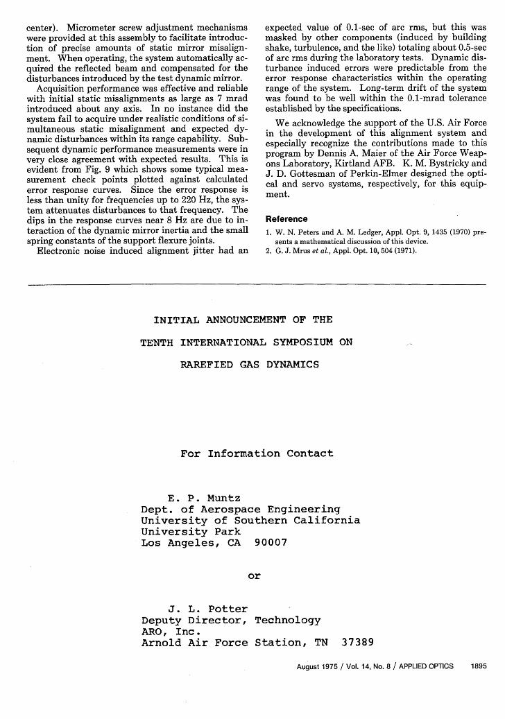
Acquisition performance was effective and reliablewith initial static misalignments as large as 7 mradintroduced about any axis. In no instance did thesystem fail to acquire under realistic conditions of si-multaneous static misalignment and expected dy-namic disturbances within its range capability. Sub-sequent dynamic performance measurements were invery close agreement with expected results. This isevident from Fig. 9 which shows some typical mea-surement check points plotted against calculatederror response curves. Since the error response isless than unity for frequencies up to 220 Hz, the sys-tem attenuates disturbances to that frequency. Thedips in the response curves near 8 Hz are due to in-teraction of the dynamic mirror inertia and the smallspring constants of the support flexure joints.
Electronic noise induced alignment jitter had an
expected value of 0.1-sec of arc rms, but this wasmasked by other components (induced by buildingshake, turbulence, and the like) totaling about 0.5-secof arc rms during the laboratory tests. Dynamic dis-turbance induced errors were predictable from theerror response characteristics within the operatingrange of the system. Long-term drift of the systemwas found to be well within the 0.1-mrad toleranceestablished by the specifications.
We acknowledge the support of the U.S. Air Forcein the development of this alignment system andespecially recognize the contributions made to thisprogram by Dennis A. Maier of the Air Force Weap-ons Laboratory, Kirtland AFB. K. M. Bystricky andJ. D. Gottesman of Perkin-Elmer designed the opti-cal and servo systems, respectively, for this equip-ment.
Reference1. W. N. Peters and A. M. Ledger, Appl. Opt. 9, 1435 (1970) pre-
sents a mathematical discussion of this device.2. G. J. Mrus et al., Appl. Opt. 10, 504 (1971).
INITIAL ANNOUNCEMENT OF THE
TENTH INTERNATIONAL SYMPOSIUM ON
RAREFIED GAS DYNAMICS
For Information Contact
E. P. MuntzDept. of Aerospace EngineeringUniversity of Southern CaliforniaUniversity ParkLos Angeles, CA 90007
or
J. L. PotterDeputy Director, TechnologyARO, Inc.Arnold Air Force Station, TN 37389
August 1975 / Vol. 14, No. 8 / APPLIED OPTICS 1895