73502 011090 Gysmi tig 160 DC FR-EN-DE V1 · Recommandation sur les méthodes de réduction des...
20
03042012-V1 P : 02-07 / 18-20 P : 08-12 / 18-20 P : 13-17 / 18-20
Transcript of 73502 011090 Gysmi tig 160 DC FR-EN-DE V1 · Recommandation sur les méthodes de réduction des...

03042012-V1
P : 02-07 / 18-20 P : 08-12 / 18-20
P : 13-17 / 18-20

2/20
DESCRIPTION
Merci de votre choix ! Afin de tirer le maximum de satisfaction de votre poste, veuillez lire avec attention ce qui suit : Le TIG 160 DC est un poste de soudure Inverter, portable, ventilé, pour soudage à l’électrode enrobée (MMA) et à électrode réfractaire (TIG Lift) en courant continu (DC). En MMA, il soude tout type d’électrode : rutile, inox, fonte, basique. Il fonctionne sur une alimentation électrique monophasée 230V. En TIG, il soude la plupart des métaux sauf l’aluminum et ses alliages. Il est protégé pour le fonctionnement sur groupes électrogènes (Alim 230 V +- 15%).
ALIMENTATION-MISE EN MARCHE
• Le poste est livré avec une prise 230V 16A de type CEE7/7. Il doit être relié à une installation électrique 230 V (50 - 60 Hz) AVEC terre. Le courant effectif absorbé (I1eff) est indiqué sur l'appareil pour les conditions d'utilisation maximales. Vérifier que l'alimentation et ses protections (fusible et/ou disjoncteur) sont compatibles avec le courant nécessaire en utilisation. Dans certains pays, il peut être nécessaire de changer la prise pour permettre une utilisation aux conditions maximales. En utilisation intensive, utiliser de préférence une installation électrique 20A. L'utilisateur doit s'assurer de l'accessibilité de la prise.
• La mise en marche s’effectue par une pression sur la touche « ON / VEILLE » � .L’appareil se met en protection si la tension d'alimentation est supérieure à 265V. Pour indiquer ce défaut, l’afficheur indique . Le fonctionnement normal reprend une trentaine de seconde après que la tension d'alimentation soit revenue dans sa plage nominale.
• Cet appareil à usage professionnel, classe A, est destiné à être connecté à des réseaux privés raccordés au réseau public d’alimentation seulement en moyenne et haute tension. I l n’est pas prévu pour être utilisé dans un site résidentiel où le courant électrique est fourni par le système public d’alimentation basse tension. Il peut y avoir des difficultés potentielles pour assurer la compatibilité électromagnétique dans ces sites, à cause de perturbations conduites aussi bien que rayonnées.
• Ce matériel ne respecte pas la CEI 61000-3-12. Avant de le connecter au système public d’alimentation basse tension, il est de la responsabilité de l’utilisateur de s’assurer qu’il peut y être relié. Consulter si nécessaire l’opérateur de votre réseau de distribution électrique.
• Ne pas utiliser dans un environnement comportant des poussières métalliques conductrices.
SOUDAGE A L'ÉLECTRODE ENROBEE (mode MMA) • Brancher les câbles porte électrode et pince de masse dans les connecteurs. Respecter les polarités
indiquées sur l'emballage des électrodes. • Respecter les règles classiques du soudage. • Votre appareil est muni de 3 fonctionnalités spécifiques aux Inverters :
Le Hot Start (mode réglable, cf ci-dessous) procure une surintensité en début de soudage. L’Arc Force délivre une surintensité qui évite le collage lorsque l’électrode rentre dans le bain. L'Anti-Sticking vous permet de décoller facilement votre électrode sans la faire rougir en cas de collage.
Activation du mode MMA et réglage de l’intensité : - Sélectionner la position MMA � avec le sélecteur � en appuyant jusqu’à ce que le voyant MMA soit
allumé - Régler l’intensité souhaitée (afficheur �) grâce aux touches �.
Hot start réglable : Le Hot Start est réglable de 0 à 60%, dans la limite de 160 A.
Conseils : Hot start faible, pour les tôles fines– Hot start élevé pour les métaux difficiles à souder (pièces sales ou oxydées)
3/20
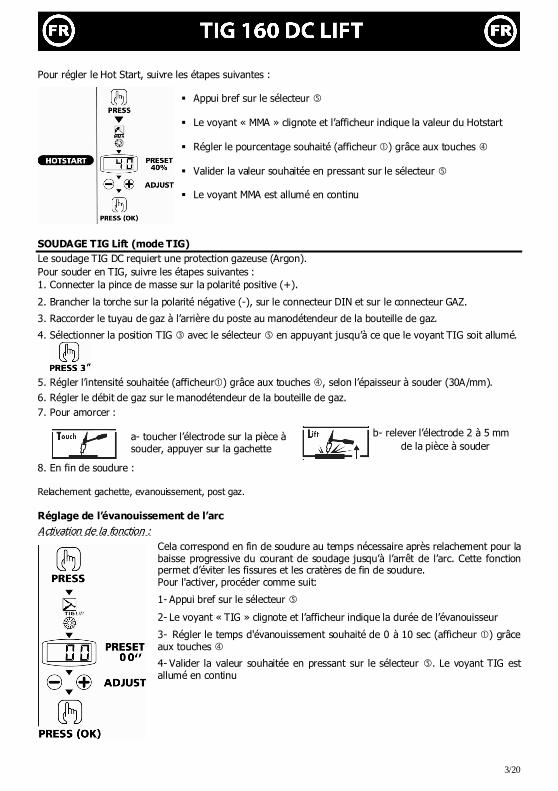
Pour régler le Hot Start, suivre les étapes suivantes :
� Appui bref sur le sélecteur �
� Le voyant « MMA » clignote et l’afficheur indique la valeur du Hotstart
� Régler le pourcentage souhaité (afficheur �) grâce aux touches �
� Valider la valeur souhaitée en pressant sur le sélecteur �
� Le voyant MMA est allumé en continu
SOUDAGE TIG Lift (mode TIG) Le soudage TIG DC requiert une protection gazeuse (Argon). Pour souder en TIG, suivre les étapes suivantes : 1. Connecter la pince de masse sur la polarité positive (+).
2. Brancher la torche sur la polarité négative (-), sur le connecteur DIN et sur le connecteur GAZ.
3. Raccorder le tuyau de gaz à l’arrière du poste au manodétendeur de la bouteille de gaz.
4. Sélectionner la position TIG � avec le sélecteur � en appuyant jusqu’à ce que le voyant TIG soit allumé.
5. Régler l’intensité souhaitée (afficheur�) grâce aux touches �, selon l’épaisseur à souder (30A/mm).
6. Régler le débit de gaz sur le manodétendeur de la bouteille de gaz.
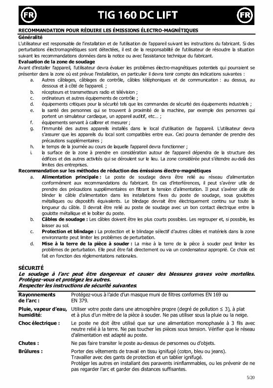
7. Pour amorcer :
b- relever l’électrode 2 à 5 mm de la pièce à souder
8. En fin de soudure : Relachement gachette, evanouissement, post gaz. Réglage de l’évanouissement de l’arc
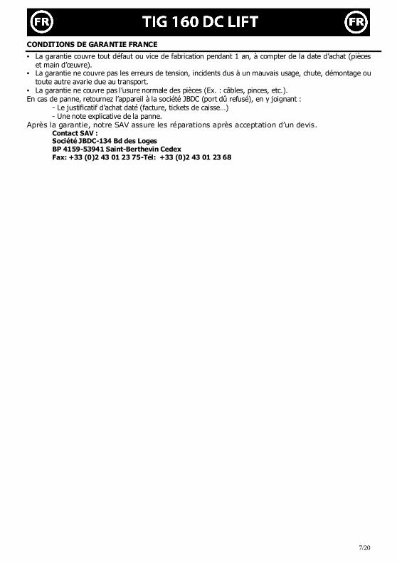
Activation de la fonction :
Cela correspond en fin de soudure au temps nécessaire après relachement pour la baisse progressive du courant de soudage jusqu’à l’arrêt de l’arc. Cette fonction permet d’éviter les fissures et les cratères de fin de soudure. Pour l'activer, procéder comme suit:
1- Appui bref sur le sélecteur �
2- Le voyant « TIG » clignote et l’afficheur indique la durée de l’évanouisseur
3- Régler le temps d'évanouissement souhaité de 0 à 10 sec (afficheur �) grâce aux touches �
4- Valider la valeur souhaitée en pressant sur le sélecteur �. Le voyant TIG est allumé en continu
a- toucher l’électrode sur la pièce à souder, appuyer sur la gachette

4/20
Combinaisons conseillées / affutage électrode
Courant (A) ∅∅∅∅ Electrode (mm) = ∅∅∅∅ fil (métal d’apport)
∅∅∅∅ Buse (mm)
Débit (Argon l/mn)
0,5-5 10-130 1,6 9,8 6-7 4-7 130-160 2,4 11 7-8
Pour un fonctionnement optimal vous devez utiliser une électrode affûtée de la manière suivante :
d
l Connecteur de commande gâchette PROTECTION THERMIQUE ET FACTEURS DE MARCHE • Protection thermique : le voyant � s’allume et la durée de refroidissement est de 1 à 5 mn en fonction de
la température ambiante. • Laisser l’appareil branché après soudage pour permettre le refroidissement • Les postes décrits ont une caractéristique de sortie de type "courant constant". Leurs facteurs de marche
selon la norme EN60974-1 sont indiqués dans le tableau suivant :
Note : les essais d’échauffement ont été effectués à température ambiante et le facteur de marche à 40 °C a été déterminé par simulation. ENTRETIEN
• L'entretien ne doit être effectué que par une personne qualifiée. • Couper l'alimentation en débranchant la prise, et attendre l’arrêt du ventilateur avant de travailler sur
l'appareil. A l’intérieur, les tensions et intensités sont élevées et dangereuses. • Il est conseillé 2 à 3 fois par an d’enlever le capot et dépoussiérer à la soufflette. En profiter pour faire
vérifier la tenue des connexions électriques avec un outil isolé par un personnel qualifié. • Contrôler régulièrement l'état du cordon d'alimentation. Si le câble d'alimentation est endommagé, il
doit être remplacé par le fabricant, son service après vente ou une personne de qualification similaire, afin d'éviter un danger
NOS CONSEILS • Respecter les polarités et intensités de soudage indiquées sur les boîtes d'électrodes • Enlever l’électrode du porte-électrode lorsque le poste n'est pas utilisé. • Laisser les ouïes de l'appareil libres pour l’entrée et la sortie d’air.
L = 2,5 x d. L
GYSMI TIG 160 DC
X% @ I max X% @ I max
19% 160A 24% 160A
60% 95A 60% 105A
100% 75A 100% 95A
3
1
2, 4 et 5 : non connectés.
5/20
RECOMMANDATION POUR RÉDUIRE LES ÉMISSIONS ÉLECTRO-MAGNÉTIQUES Généralité L’utilisateur est responsable de l’installation et de l’utilisation de l’appareil suivant les instructions du fabricant. Si des perturbations électromagnétiques sont détectées, il est de la responsabilité de l’utilisateur de résoudre la situation suivant les recommandations données dans la notice ou avec l’assistance technique du fabricant. Evaluation de la zone de soudage Avant d’installer l’appareil, l’utilisateur devra évaluer les problèmes électro-magnétiques potentiels qui pourraient se présenter dans la zone où est prévue l’installation, en particulier il devra tenir compte des indications suivantes :
a. Autres câblages, câblages de contrôle, câbles téléphoniques et de communication : au dessus, au dessous et à côté de l’appareil. ;
b. récepteurs et transmetteurs radio et télévision ; c. ordinateurs et autres équipements de contrôle ; d. équipements critiques pour la sécurité tels que les commandes de sécurité des équipements industriels ; e. la santé des personnes qui se trouvent à proximité de la machine, par exemple des personnes qui
portent un simulateur cardiaque, un appareil auditif, etc… ; f. équipements servant à calibrer et mesurer ; g. l’immunité des autres appareils installés dans le local d’utilisation de l’appareil. L’utilisateur devra
s’assurer que les appareils du local sont compatibles entre eux. Ceci pourra demander de prendre des précautions supplémentaires ;
h. le temps de la journée au cours de laquelle l’appareil devra fonctionner ; i. la surface de la zone à prendre en considération autour de l’appareil dépendra de la structure des
édifices et des autres activités qui se déroulent sur le lieu. La zone considérée peut s’étendre au-delà des limites des entreprises.
Recommandation sur les méthodes de réduction des émissions électro-magnétiques a. Alimentation principale : Le poste de soudage devra être relié au réseau d’alimentation
conformément aux recommandations du fabricant. En cas d’interférences, il peut s’avérer utile de prendre des précautions supplémentaires en filtrant la tension d’alimentation. Il peut s’avérer utile de blinder le câble d’alimentation dans les installations fixes du poste de soudage, sous goulottes métalliques ou dispositifs équivalents. Le blindage devrait être électriquement continu sur toute la longueur du câble. Il devrait être relié au poste de soudage avec un bon contact électrique entre la goulotte métallique et le boîtier du poste.
b. Câbles de soudage : Les câbles doivent être les plus courts possibles. Les regrouper et, si possible, les laisser au sol.
c. Protection et blindage : La protection et le blindage sélectif d’autres câbles et matériels dans la zone environnante peut limiter les problèmes de perturbation.
d. Mise à la terre de la pièce à souder : La mise à la terre de la pièce à souder peut limiter les problèmes de perturbation. Elle peut être fait directement ou via un condensateur approprié. Ce choix est fait en fonction des réglementations nationales.
SÉCURITÉ Le soudage à l'arc peut être dangereux et causer des blessures graves voire mortelles. Protégez-vous et protégez les autres. Respecter les instructions de sécurité suivantes:
Rayonnements Protégez-vous à l’aide d’un masque muni de filtres conformes EN 169 ou de l’arc : EN 379.
Pluie, vapeur d’eau, Utiliser votre poste dans une atmosphère propre (degré de pollution ≤ 3), à plat humidité: et à plus d’un mètre de la pièce à souder. Ne pas utiliser sous la pluie ou la neige.
Choc électrique : Le poste ne doit être utilisé que sur une alimentation monophasée à 3 fils avec neutre relié à la terre. Ne pas toucher les pièces sous tension. Vérifier que le réseau d'alimentation est adapté au poste.
Chutes : Ne pas faire transiter le poste au-dessus de personnes ou d’objets.
Brûlures : Porter des vêtements de travail en tissu ignifugé (coton, bleu ou jeans). Travailler avec des gants de protection et un tablier ignifugé. Protéger les autres en installant des paravents ininflammables, ou les prévenir de ne
pas regarder l'arc et garder des distances suffisantes.

6/20
Risques de feu : Supprimer tous les produits inflammables de l'espace de travail. Ne pas travailler en présence de gaz inflammable.
Fumées : Ne pas inhaler les gaz et fumées de soudage. Utiliser dans un environnement correctement ventilé, avec extraction artificielle si soudage en intérieur.
Précautions Toute opération de soudage : supplémentaires : - dans des lieux comportant des risques accrus de choc électrique, - dans des lieux fermés, - en présence de matériau inflammable ou comportant des risques d'explosion, doit toujours être soumise à l'approbation préalable d'un "responsable expert", et
effectuée en présence de personnes formées pour intervenir en cas d'urgence. Les moyens techniques de protections décrits dans la Spécification Technique
CEI/IEC 62081 doivent être appliqués. Le soudage en position surélevée est interdit, sauf en cas d'utilisation de plates-
formes de sécurité.
Les porteurs de stimulateurs cardiaques doivent consulter un médecin avant d'utiliser ces appareils.
Ne pas utiliser le poste pour dégeler des canalisations. En soudage TIG, manipuler la bouteille de gaz avec précaution, des risques existent si la
bouteille ou la soupape de la bouteille sont endommagées.
ANOMALIES, CAUSES, REMEDES
Anomalies Causes Remèdes L’appareil ne délivre pas de courant et le voyant jaune de défaut thermique est allumé �.
La protection thermique du poste s’est enclenchée.
Attendre la fin de la période de refroidissement, environ 2 min. Le voyant � s’éteint.
L’afficheur est allumé mais l’appareil ne délivre pas de courant.
Le câble de pince de masse ou porte électrode n’est pas connecté au poste.
Vérifier les branchements.
Le poste est alimenté, vous ressentez des picotements en posant la main sur la carrosserie.
La mise à la terre est défectueuse.
Contrôler la prise et la terre de votre installation.
Le poste soude mal Erreur de polarité Vérifier la polarité conseillée sur la boîte d'électrode.
Lors de la mise en route, l’afficheur indique
La tension d’alimentation n’est pas dans la fourchette 230 V +/- 15%
Vérifier votre installation électrique ou votre groupe électrogène
Utiliser une électrode en tungstène de taille appropriée Défaut provenant de l'électrode
en tungstène Utiliser une électrode en tungstène correctement préparée
Arc instable
Débit de gaz trop important Réduire le débit de gaz
Zone de soudage. Protéger la zone de soudage contre les courants d'air. L'électrode en tungstène
s'oxyde et se ternit en fin de soudage Problème de gaz, ou coupure
prématurée du gaz
Contrôler et serrer tous les raccords de gaz. Attendre que l'électrode refroidisse avant de couper le gaz.
L'électrode fond Erreur de polarité Vérifier que la pince de masse est bien reliée au +
7/20
CONDITIONS DE GARANTIE FRANCE
• La garantie couvre tout défaut ou vice de fabrication pendant 1 an, à compter de la date d’achat (pièces et main d’œuvre).
• La garantie ne couvre pas les erreurs de tension, incidents dus à un mauvais usage, chute, démontage ou toute autre avarie due au transport.
• La garantie ne couvre pas l’usure normale des pièces (Ex. : câbles, pinces, etc.). En cas de panne, retournez l’appareil à la société JBDC (port dû refusé), en y joignant :
- Le justificatif d’achat daté (facture, tickets de caisse…) - Une note explicative de la panne.
Après la garantie, notre SAV assure les réparations après acceptation d’un devis. Contact SAV : Société JBDC-134 Bd des Loges BP 4159-53941 Saint-Berthevin Cedex Fax: +33 (0)2 43 01 23 75-Tél: +33 (0)2 43 01 23 68
8/20
Thank you for choosing this machine. To get the best from your machine, please read the following carefully:
The TIG 160 DC LIFT is a portable Inverter welder, for electrode welding (MMA) and TIG Lift in DC. It allows welding with rutile, basic, stainless steel and cast iron electrodes. It works on a single phase 230V power supply. In TIG, it will weld most of metals except aluminium and alloys. It is protected for a use on electric generators (230V /+- 15% or 400V/+-15 %). POWER SUPPLY – START UP
• This machine is delivered with a 230V socket /16A plug type EEC7/7. The TIG 160 DC must be connected to a 230 V socket (50-60Hz) EARTHED power supply. The absorbed effective current (I1eff) is indicated on the machine at maxiumum usage. Check that the power supply and its protection (fuse and/or circuit-breaker) are compatible with the necessary current needed for use. In some countries, it might be necessary to change the plug to allow maximum performance. The welder must be installed so that the main plug is always accessible.
• To turn on the machine press ON / STAND BY.
• The device will turn on in protection mode if the power supply voltage is over 265V. To indicate this fault the screen displays . Normal operation will resume after thirty seconds when the voltage has returned to within its normal range.
• This class A device is designed to be used in an industrial or professional environment. This equipment is not intended for use in residential locations where the electrical power is provided by the public low-voltage supply system. It can be difficult to ensure electromagnetic compatibility, due to conducted disturbances as well as radiation.
• This material does not comply with IEC 61000-3-12. If it is to be connected to a low-voltage mains supply, it is the responsibility of the user to ensure it can be connected. If necessary consult the operator of your electrical distribution system.
ELECTRODE WELDING (MMA Mode)
• Connect the earth and electrode-holder cables. Respect the polarity indicated on the electrodes’ packaging.
• Apply the usual welding rules. • Your machine is equipped with 3 specific functions : Hot Start (adjustable mode, see below) increases the current at the beginning of the welding. Arc Force increases the current in order to avoid sticking when the electrode enters the weld pool. Anti Sticking allows you to easily remove your electrode without damaging it in case of sticking.
Selection of MMA Mode and intensity setting : - Select the MMA position � with the selector � until the MMA indicator illuminates - Adjust the desired current (display �) using the key �. Hot Start adjustment Hot Start is adjustable from 0 to 60% within the limit of 160A. Advice: low Hot Start: for thin metal sheets – high Hot Start for metals that are difficult to weld (dirty or oxidized parts).
To adjust the Hot Start follow these steps:
� Press the selector � briefly � The "MMA" LED starts flashing and the display indicates the current
Hot Start value. � Set the required percentage ( display �) using keys � � Validate the required figure by pressing the selector button � � The "MMA" LED remains illuminated

9/20
TIG WELDING (TIG LIFT MODE)
The DC TIG welding requires a protective gas (argon). Follow the steps below:
1. Connect the earth clamp to the positive socket (+).
2. Connect the torch to the negative socket (-), the DINSE connector and the gas connector.
3. Connect the gas pipe from the rear of the welder to the flowmeter of the gas cylinder
4. Select TIG mode � using the selector button�, press until the TIG indicator illuminates.
5. Adjust the desired current (display�) using the keys�, according to the thickness of the metal workpiece (30A / mm).
6. Set the gas flow on flowmeter.
7. To start :
b- Raise the electrode to between 2 - 5 mm from the workpiece.
8. When finished: Release the trigger, downslope, post-gas
Adjustment of downslope Function activation:
This function allows the user to adjust the time required at the end of welding for the gradual decline in the welding current until the arc stops. This function helps to avoid cracks and craters at end of welding. To activate it, proceed as follows:
1- Press the selector button � for 3 seconds
2- The TIG indicator starts flashing and the display indicates the current downslope time
3- Set the automatic arc downslope you wish from 0 to 10 sec (display�) using key�.
4- Validate your choice pressing button �. The TIG indicator remains
illuminated.
Recommended combinations / Electrode grinding
Current (A) Ø Electrode (mm) = Ø wire (filler metal)
Ø Nozzle (mm) Flow rate (Argon L/mn)
0.5-5 10-130 1.6 9.8 6-7 4-7 130-190 2.4 11 7-8
To optimise the welding process, it is recommended to grind the electrode prior to welding as described in
the diagram below:
d
l
DIN connector – Torch command
L = 3 x d for a low current L = d for a strong current
L
3
1
2, 4 & 5 : not connected
a- Touch the electrode on the welding workpiece

10/20
THERMAL PROTECTION & DUTY CYCLE
• Thermal protection: the thermal protection indicator � turns on and the cooling time is about 1 to 5 min depending on external temperature.
• Leave the machine connected to the power supply after welding in order to let it cool down • The welding unit describes an output characteristic of "constant current" type. The duty cycles following
the norm EN60974-1 (at 40°C on a 10mn cycle) are indicated in the table below :
Note: The machine's duty cycle has been tested at room temperature (40°C) and have been determined by simulation.
MAINTENANCE
• Maintenance should be carried out by a qualified person. • Ensure the machine is unplugged, and that the ventilator inside has stopped before carrying out
maintenance work (DANGER High Voltage and Currents). • JBDC recommends removing the steel cover 2 or 3 times a year to remove any excess dust. Take this
opportunity to have the electrical connections checked by a qualified person with an insulated tool. • Regularly check the condition of the power supply cord. If damaged it will need to be replaced by the
manufacturer, it's after sales service or a qualified person.
ADVICE • Respect welding polarities and currents indicated on the electrode packaging • Remove the electrode from the electrode holder when not in use. • Ensure air vents are not covered to allow adequate air circulation.
RECOMMENDATIONS FOR REDUCTION OF ELECTRO-MAGNETIC EMISSIONS
The user is responsible for installing and using the arc welding equipment according to the manufacturer’s instructions. If electromagnetic disturbances are detected, then it is the responsibility of the user to resolve the situation with the technical assistance of the manufacturer.
Evaluation of the welding area An assessment of potential electromagnetic problems in the surrounding area should be made before installing the welding machine: a) Other wiring, power cables, tephone and communication cables; above, below and adjacent to the welding machine
b) Radio and television transmitters and receivers; c) Computers or other electronic equipment; d) Equipment critical for safety purposes (such as safety checks of industrial equipment); e) Persons using medical equipment, eg pacemakers and hearing aids; f) Equipment used for calibration or measurements; g) The user must ensure that other equipment used in the same area is compatible. This may require additional safety measures;
h) The time of day when welding or other activities are carried out i) The size of the area to be used; the structure of the building and any other processes in the area. The surrounding area may extend beyond the boundaries of the building.
Recommendation for methods to reduce the electro-magnetic emission a. Mains power supply: the equipment must be connected to the power supply as specified in the Manufacturer’s
instructions. If interference occurs, additional precautions such as filtering of the mains supply may be required. The power cable should be shielded in fixed installations, in metal conduits or similar. The shielding should be continous for the entire lengh of the cable. It should also be connect to the welding machine with good electrical contact between the metal conduit and the casing.
b. Welding cables: The welding cables should be kept as short as possible and should be positioned close together, running at or close to the floor level.
TIG 160 DC LIFT
X% @ I max X% @ I max
19% 160A 24% 160A
60% 95A 60% 105A
100% 75A 100% 95A

11/20
c. Protection and reinforcement: Selective shielding of other cables and equipment in the surrounding area may alleviate problems of interference. Shielding of the entire welding area may be considered for special applications
d. Connect the earth directly to the metal workpiece: Where necessary, the connection of the workpiece to an earth should be made direcltly, but in some countries where direct connection is not permitted, the earth connection should be achieved by suitable capacitance, selected according to national regulations.
SAFETY Arc welding can be dangerous and can cause serious and even fatal injuries. Protect yourself and protect the others. Ensure the following safety precautions are taken:
Arc rays: Protect yourself with a helmet fitted with filters in compliance with EN169 or EN379. Ensure you inform and protect other people in the welding environment.
Rain, steam, Use your welding unit in a clean/dry environment (pollution factor ≤ 3), on a flat Humidity surface, and more than one meter from the welding work-piece. Do not use in rain or snow.
Electric shocks: This device must only be used with an earthed power supply. Do not touch the High voltage parts. Check that the power supply is suitable for this unit.
Moving: Do not underestimate the weight of the apparatus. Do not move the unit over people or objects. Do not drop it. Do not set the unit down heavily.
Burns: Wear protective (fire-proof) clothing (cotton, overalls or jeans). Wear protective gloves and a fire-proof apron. Ensure other people keep a safe distance from the work area and do not look directly at the welding arc Protect others by installing fire-proof protection walls
Fire risks: Remove all flammable products from the work area. Do not work in presence of flammable gases.
Fumes: Do not inhale welding gases and fumes. Use the device in a well ventilated environment, with artificial extraction if welding indoors.
Extra precautions: Any welding operation undertaken in: - Environments with increased risk of electric shock, - Poorly ventillated rooms, - The presence of flammable or explosive materials
must always be approved by a "responsible expert", and made in presence of people trained to intervene in case of emergency.
Technical protection as described in the TECHNICAL SPECIFICATION "IEC 62081" MUST BE taken.
Welding in raised positions is forbidden unless safety platforms are used.
People wearing Pacemakers are advised to see their doctor before using this device Do not use this device to unfreeze pipes.
Handle gas bottles with care - there is increased danger if the bottle or its valve are damaged.

12/20
TROUBLESHOOTING
Anomalies Causes Remedies The device does not deliver any current and the yellow thermal fault light � illuminates
The thermal protection is on Wait for the end of the cooling time, around 2 minutes. The indicator lamp � turns off.
The display is on but the device does not deliver any current.
The earth clamp or electrode holder is not properly connected to the unit.
Check the connections.
When on, the user feels a tingling sensation when touching the machine.
The welding unit is not correctly connected to the earth.
Check the plug and the earth of your electrical network.
Your unit does not weld correctly.
Polarity error. Check the polarity advised on the electrode packaging.
When starting up, the display indicates
The voltage is not within the range 230V +/- 15%
Have the electrical installation checked. Use a tungsten electrode with the correct size
Fault originates from the tungsten electrode
Use a well prepared tungsten electrode
Unstable arc
Gas flow rate is too high Reduce gas flow rate
Working area Protect welding zone against air flow
Increase post-gas duration
The tungsten electrode becomes oxidised and tarnishes at the end of welding. Fault originating from post-
gas, or the gas has been interrupted.
Check and tighten all gas connections. Ensure the electrode has cooled down before stopping the gas.
The electrode melts Polarity error Check that the earth clamp is connected to the +.

13/20
Wir freuen uns, dass Sie sich für ein Markengerät der Firma JBDC entschieden haben und danken Ihnen für das entgegengebrachte Vertrauen. Bitte lesen Sie sorgfältig vor dem Erstgebrauch diese Betriebsanleitung. Das TIG 160 DC LIFT ist ein tragbares, luftgekühltes Schweißinverter, konzipiert um Schweißarbeiten an ummantelten- (MMA) und hitzebeständigen (WIG Lift) Elektroden bei Gleichstrom (DC) durchführen zu können. Im MMA Modus können alle gängigen Rutil-, Edelstahl-, Guss-, und basischen Stabelektroden verschweißt werden. Das Gerät wird an eine 230V- einphasige Stromversorgung angeschlossen. Im WIG Modus ist es möglich die meisten Metalle mit Ausnahme von Legierungen und Aluminium zu schweißen. Diese Geräte sind generatortauglich und gegen Überspannung geschützt (230V +/- 15%).
STROMVERSORGUNG-INBETRIEBNAHME
• Das Gerät TIG 160 DC LIFT wird mit einem 16 A CEE7/7- Stecker geliefert [Anschluss: 230V (50-60 Hz) + Schutzleiter]. Der aufgenommene Strom (I1eff) ist am Gerät aufgedruckt. Überprüfen Sie, ob die Stromversorgung und die Schutzeinrichtungen (Sicherungen und/oder Schutzschalter) mit dem Strom, den Sie beim Schweißen benötigen, übereinstimmen. In einigen Ländern ist es notwendig einen anderen Stecker zu verwenden, um bei maximaler Belastung arbeiten zu können. Achten Sie während des Schweißens auf einen sicheren Stand des Gerätes und einen frei zugänglichen Netzanschluss.
• Zum Starten drücken Sie die Standby/EIN Taste. • Das Gerät hat einen Überspannungsschutz, welcher beim Überschreiten 265V Netzspannung in den Stand-
By-Modus schaltet. Dieser Fehler wird mit angezeigt. Sinkt die Netzspannung innerhalb von 30 Sek. wieder unter den maximalen Spannungswert, geht das Gerät automatisch in Betriebsbereitschaft.
• Dieses Klasse A Gerät ist nicht für den Einsatz in Wohngebieten bestimmt, in denen Stromversorgung vom öffentlichen Niederspannungsnetz geregelt wird. Es kann sowohl zu leitungs- als auch feldgebundenen elektromagnetischen Störungen kommen.
• Dieses Gerät entspricht nicht mehr der Richtlinie CEI 61000-3-12. Es liegt in Ihrer Verantwortung zu überprüfen, ob die Geräte für den Stromanschluss geeignet sind, bevor Sie sie an das Stromnetz anschließen. Bei Fragen wenden Sie sich bitte an den zuständigen Stromnetzbetreiber.
SCHWEISSEN MIT UMHÜLLTEN ELEKTRODEN (MMA MODUS)
• Schließen Sie Elektroden- und Massekabel an die entsprechenden Anschlüsse an. Beachten Sie die auf der Elektrodenpackung beschriebenen Polaritätsangaben
• Beachten Sie die allgemeinen Regeln zur Unfallprävention beim Schweißen • Ihr Schweißgerät ist mit drei spezifischen Funktionen zur Verbesserung der Schweißeigenschaften
ausgerüstet: Hot Start Erhöht den Schweißstrom beim Zünden der Elektrode Arc Force Erhöht kurzzeitig den Schweißstrom. Ein mögliches Festbrennen (Sticking) der
Elektrode am Werkstück während des Eintauchens ins Schweißbad wird verhindert. Anti Sticking: Verbessert den Einbrand und verhindert mögliches Festbrennen
Auswahl der Betriebsart und Stromstärke: - Wählen Sie mit der Drucktaste � den MMA Modus � aus - Wählen Sie mit der Drucktaste � die gewünschte Stromstärke (Anzeige �) aus
Konfiguration Hot Start
- Der Hot Start ist zwischen 0 und 60% einstellbar. Die Stromgrenze liegt bei 160A. Hinweis: Niedriger Hot Start für dünne Metallbleche; hoher Hot Start für schwer zu schweißende Metalle mit verschmutzen oder oxidierten Stellen.
Um Hot Start einzustellen, gehen Sie wie folgt vor: � Drücken Sie die Taste � � Die Anzeige MMA blinkt, dann erscheint der Wert des Hot Start � Stellen Sie den Prozentsatz (Anzeige�) mithilfe der Taste � ein
� Bestätigen Sie die gewünschte Einstellung mit der Taste � � Die Anzeige MMA leuchtet
14/20
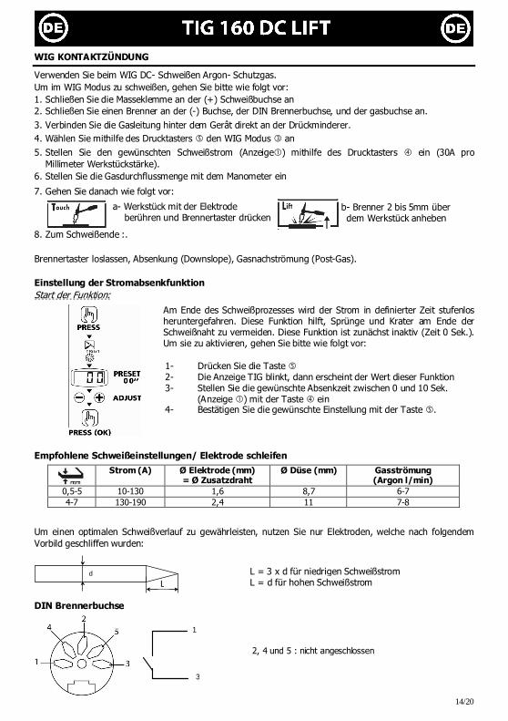
WIG KONTAKTZÜNDUNG
Verwenden Sie beim WIG DC- Schweißen Argon- Schutzgas. Um im WIG Modus zu schweißen, gehen Sie bitte wie folgt vor: 1. Schließen Sie die Masseklemme an der (+) Schweißbuchse an 2. Schließen Sie einen Brenner an der (-) Buchse, der DIN Brennerbuchse, und der gasbuchse an.
3. Verbinden Sie die Gasleitung hinter dem Gerât direkt an der Drückminderer.
4. Wählen Sie mithilfe des Drucktasters � den WIG Modus � an
5. Stellen Sie den gewünschten Schweißstrom (Anzeige�) mithilfe des Drucktasters � ein (30A pro Millimeter Werkstückstärke).
6. Stellen Sie die Gasdurchflussmenge mit dem Manometer ein
7. Gehen Sie danach wie folgt vor:
a- Werkstück mit der Elektrode berühren und Brennertaster drücken
8. Zum Schweißende :. Brennertaster loslassen, Absenkung (Downslope), Gasnachströmung (Post-Gas). Einstellung der Stromabsenkfunktion Start der Funktion:
Am Ende des Schweißprozesses wird der Strom in definierter Zeit stufenlos heruntergefahren. Diese Funktion hilft, Sprünge und Krater am Ende der Schweißnaht zu vermeiden. Diese Funktion ist zunächst inaktiv (Zeit 0 Sek.). Um sie zu aktivieren, gehen Sie bitte wie folgt vor:
1- Drücken Sie die Taste � 2- Die Anzeige TIG blinkt, dann erscheint der Wert dieser Funktion 3- Stellen Sie die gewünschte Absenkzeit zwischen 0 und 10 Sek.
(Anzeige �) mit der Taste � ein 4- Bestätigen Sie die gewünschte Einstellung mit der Taste �.
Empfohlene Schweißeinstellungen/ Elektrode schleifen
Strom (A) Ø Elektrode (mm) = Ø Zusatzdraht
Ø Düse (mm) Gasströmung (Argon l/min)
0,5-5 10-130 1,6 8,7 6-7 4-7 130-190 2,4 11 7-8
Um einen optimalen Schweißverlauf zu gewährleisten, nutzen Sie nur Elektroden, welche nach folgendem Vorbild geschliffen wurden:
d
l
DIN Brennerbuchse
b- Brenner 2 bis 5mm über dem Werkstück anheben
L = 3 x d für niedrigen Schweißstrom L = d für hohen Schweißstrom L
3
1
2, 4 und 5 : nicht angeschlossen

15/20
THERMISCHE ÜBERWACHUNG & EINSCHALTDAUER
• Thermischer Überlastschutz (Anzeige �): Lassen Sie das Gerät sich- je nach Umgebungstemperatur- 1 bis 5 min abkühlen, bis die Kontrollanzeige erlischt
• Lassen Sie das Gerät auch nach Schweißende einige Zeit am Stromnetz angeschlossen, damit sich das TIG abkühlen kann
Die JBDC-Schweißgeräte entsprechen in ihrer Charakteristik einer Konstantstromquelle. Die Einschaltdauer entspricht wie unten beschrieben der Norm EN60974-1 (bei 40°C und einem 10min Zyklus):
Hinweis: Der Überhitzungstest wurde bei Raumtemperatur durchgeführt und die Einschaltdauer bei 40°C durch Simulation ermittelt.
INSTANDHALTUNG
• Die Instandhaltungsarbeiten dürfen nur von qualifiziertem Fachpersonal durchgeführt werden • Nehmen Sie regelmäßig (mindestens 2 bis 3 Mal im Jahr) das Gehäuse ab und reinigen Sie das Innere des
Gerätes mit Pressluft. Lassen Sie regelmäßig Prüfungen des JBDC Geräts auf seine elektrische Betriebssicherheit von qualifiziertem Fachpersonal durchführen
• Trennen Sie vor dem Öffnen des JBDC Gerätes die Stromversorgung zum Gerät und warten Sie, bis der Ventilator sich nicht mehr dreht. Im Gerät sind die Spannungen sehr hoch und deshalb gefährlich
• Prüfen Sie regelmäßig den Zustand der Netzzuleitung. Wenn diese beschädigt ist, muss sie durch den Hersteller, seinen Reparaturservice oder eine qualifizierte Person ausgetauscht werden, um Gefahren zu vermeiden
• Verdecken Sie nicht die Lüftungsschlitze HINWEISE ZUR REDUZIERUNG VON ELEKTROMAGNETISCHEN STÖRUNGEN
Allgemein Es liegt in der Verantwortung des Anwenders dafür Sorge zu tragen, dass die Schweißausrüstung nach den Vorgaben des Herstellers angeschlossen und verwendet wird. Liegen elektromagnetische Störungen vor, ist der Anwender dafür verantwortlich dieses Problem mithilfe des technischen Supports des Herstellers zu beheben.
Prüfung des Schweißbereiches Prüfen Sie vor Anschluss der Schweißausrüstung die Arbeitsumgebung auf potentielle elektromagnetische Probleme: a) Allgemeine Verkabelung, Steuerkabel, Fernmeldekabel und Datenleitungen über, unter und in direkter Nähe des Schweißgerätes
b) Radio/ TV Sende- und Empfangsgeräte; c) Computer und andere Kontrollgeräte; d) Empfindliche Anlagen für bspw. Sicherheitsüberprüfungen von industrieller Ausrüstung; e) Gesundheitszustand (Herzschrittmacher, Hörgerät, usw.) der sich in der Umgebung des Gerätes befindlichen Personen;
f) Geräte zum Kalibrieren und Messen; g) Unempfindlichkeit anderer externer Ausrüstung in der Nähe des Gerätes. Dies kann zusätzliche Sicherheitsmaßnahmen erfodern.
h) Tageszeit, zu der Schweiß- und andere Arbeiten durchgeführt werden sollen; i) Berücksichtigung der Geräteumgebung, in Abhängigkeit der Gebäudestruktur und anderer Vorgänge am Arbeitsplatz. Diese Umgebungsgrenze kann sich auch über die Grundstücksgrenzen erstrecken. Hinweise zu den Methoden zur Reduzierung von elektromagnetischen Störungen a. Hauptstromversorgung: Die Schweißausrüstung muss nach Herstellerangeben angeschlossen werden. Treten
Störungen auf, sind eventuell weitere Sicherheitsmaßnahmen, wie die Filterung der Versorgungsspannung, notwendig.
GYSMI 160 DC LIFT
X% @ I max X% @ I max
19% 160A 24% 160A
60% 95A 60% 105A
100% 75A 100% 95A

16/20
b. Schweißkabel: Die Schweißkabel sollten so kurz wie möglich gehalten werden und gemeinsam auf bzw. möglichst nahe am Bodenbereich verlaufen.
c. Schutz und Verstärkung: Selektiver Schutz und Abschirmung von anderen Kabeln und Geräten in der Umgebung kann Störungsprobleme verringern. Das Maschinennetzkabel muss eventl. abgeschirmt werden. Die Abschrirmung muss der gesamten Kabellänge entsprechen. Achten Sie darauf, dass das Schweißgerätegehäuse extra geerdet ist.
d. Erdung des Werkstückes: Die Erdung des zu verschweißenden Werkstücks kann eventuelle Störungsprobleme verringern. Sie sollte direkt bzw. über einen entsprechenden Kondensator erfolgen, je nach landesspezifischen Vorgaben.
UNFALLPRÄVENTION
Lichtbogenschweißen kann gefährlich sein und zu schweren - unter Umständen auch tödlichen - Verletzungen führen. Schützen Sie daher sich selbst und andere. Beachten Sie unbedingt die folgenden Sicherheitshinweise:
Lichtbogenstrahlung Gesichtshaut und Augen sind durch ausreichend dimensionierte EN 175 konforme Schutzschirme mit Spezialschutzgläsern nach EN 169 / 379 vor der intensiven Ultraviolettstrahlung zu schützen. Auch in der Nähe des Lichtbogens befindliche Personen oder Helfer müssen auf Gefahren hingewiesen und mit den nötigen Schutzmitteln ausgerüstet werden.
Umgebung Benutzen Sie das Gerät nur in sauberer und gegen Nässeeinwirkung geschützter Umgebung.
Feuchtigkeit Nicht bei erhöhter Feuchtigkeit (Regen/Schnee) benutzen. Stromversorgung TIG 160 DC LIFT nur an einer einphasigen Stromversorgung mit 3 Adern (Phase,
Nullleiter und Schutzleiter) verwenden. Keine Spannungsführenden Teile berühren.
Transport Unterschätzen Sie nicht das Gewicht der Anlage. Bewegen Sie das Gerät nicht über Personen oder Sachen hinweg, und lassen Sie es nicht herunterfallen oder hart aufsetzen.
Verbrennungsgefahr Schützen Sie sich durch geeignete trockene Schweißerkleidung (Schürze, Handschuhe, Kopfbedeckung sowie feste Schuhe). Tragen Sie auch die Schutzbrille, wenn Sie Schlacke abklopfen. Schützen Sie andere durch nicht entzündbare Trennwände. Nicht in den Lichtbogen schauen und ausreichende Distanz halten.
Brandgefahr Entfernen Sie alle entflammbaren Produkte vom Schweißplatz und arbeiten Sie nicht in der Nähe von brennbaren Stoffen und Gasen
Schweißrauch Die beim Schweißen entstehenden Gase und der Rauch sind gesundheitsschädlich. Der Arbeitsplatz sollte daher gut belüftet sein und der entstehende Rauch und die Gase müssen abgesaugt werden.
Weitere Hinweise Führen Sie Schweißarbeiten • in Bereichen mit erhöhten elektrischen Risiken, • in abgeschlossenen Räumen, • in der Umgebung von entflammbaren oder explosiven Produkten nur in Anwesenheit von qualifiziertem Rettungs- und/oder Fachpersonal durch. Treffen Sie Vorsichtsmaßnahmen in Übereinstimmung mit "IEC 62081". Schweißarbeiten an Gegenständen in erhöhter Position dürfen nur auf professionell aufgebauten Gerüsten durchgeführt werden.
Halten Sie beim Arbeiten ausreichend Abstand zu Personen mit Herzschrittmacher! Personen mit Herzschrittmacher dürfen mit dem Gerät nicht ohne ärztliche Zustimmung arbeiten! Das Gerät ist nicht geeignet für das Auftauen von Leitungen! Achten Sie beim Umgang mit Gasflaschen auf sicheren Stand und Schutz des Flaschenventils! Beschädigte Flaschen stellen
ein Sicherheitsrisiko dar!

17/20
FEHLERSUCHE
Fehler Ursache Lösungen Das Gerät liefert keinen Schweißstrom und die gelbe Übertemperaturanzeige� leuchtet.
Der Übertemperaturschutz wurde ausgelöst.
Warten Sie ca. 2 min bis der Kühlvorgang abgeschlossen ist. Die Anzeige � erlischt danach.
Die Anzeige ist an, das Gerät liefert jedoch keinen Schweißstrom.
Masseklemme oder Elektrodenhalter- Kabel sind nicht korrekt mit dem Gerät verbunden.
Überprüfen Sie die Anschlüsse.
Bei Berührung des Gerätes, verspüren Sie ein leichtes Kribbeln.
Das Gerät ist nicht korrekt geerdet. Überprüfen Sie den Netzanschluss und die Erdverbindung.
Die Maschine schweißt nicht korrekt.
Polaritätsfehler. Überprüfen Sie die vom Hersteller angegebene Polarität der Elektroden.
Beim Start zeigt das Display für eine Sek. .
Die Spannung liegt außerhalb des Spannungstoleranzbereiches 230V +/- 15%
Überprüfen Sie die Netzspannung.
Benutzen Sie eine Wolfram-Elektrode von angemessener Länge.
Schlechte Wolfram-Elektrode.
Benutzen Sie eine sauber angeschliffene Elektrode.
Unstabiler Lichtbogen.
Zu hohe Gasströmung. Reduzieren Sie die Gasmenge.
Schweißumgebung. Schützen Sie die Schweißumgebung vor Wind oder Luftzug.
Erhöhen Sie die Gasnachströmzeit.
Die Wolfram-Elektrode oxidiert und verfärbt sich am Ende des Schweißvorgangs dunkel.
Fehler wird durch Gasnachströmen oder defektes Gasventil verursacht. Überprüfen Sie die Gasanschlüsse.
Die Elektrode glüht. Polaritätsfehler. Überprüfen Sie ob die Masseklemme an der (+) Buchse angeschlossen ist.
GARANTIE
Die Garantieleistung des Herstellers erfolgt ausschließlich bei Fabrikations- oder Materialfehlern, die binnen 12 Monate nach Kauf angezeigt werden (Nachweis Kaufbeleg). Nach Anerkenntnis des Garantieanspruchs durch den Hersteller bzw. seines Beauftragten erfolgen eine für den Käufer kostenlose Reparatur und ein kostenloser Ersatz von Ersatzteilen. Der Garantiezeitraum bleibt aufgrund erfolgter Garantieleistungen unverändert.
Ausschluss: Die Garantieleistung erfolgt nicht bei Defekten, die durch unsachgemäßen Gebrauch, Sturz oder harte Stöße sowie durch nicht autorisierte Reparaturen oder durch Transportschäden, die in Folge des Einsendens zur Reparatur, hervorgerufen worden sind. Keine Garantie wird für Verschleißteile (z.B. Kabel, Klemmen, Vorsatzscheiben etc.) sowie bei Gebrauchsspuren übernommen.
Das betreffende Gerät bitte immer mit Kaufbeleg und kurzer Fehlerbeschreibung ausschließlich über den Fachhandel einschicken. Die Reparatur erfolgt erst nach Erhalt einer schriftlichen Akzeptanz (Unterschrift) des zuvor vorgelegten Kostenvoranschlags durch den Besteller. Im Fall einer Garantieleistung trägt JBDC ausschließlich die Kosten für den Rückversand an den Fachhändler.

18/20
DÉCLARATION DE CONFORMITÉ :
JBDC atteste que le postes de soudure TIG 160 DC est fabriqué conformément aux exigences des directives Basse tension 2006/95/CE du 12/12/2006, et aux directives CEM 2004/108/CE du 15/12/2004. Cette conformité est établie par le respect des normes harmonisées EN60974-1 de 2005, EN 50445 de 2008, EN 60974-10 de 2007. Le marquage CE a été apposé en 2012.
DECLARATION OF COMPLIANCE :
The equipment described on this manual is complies with the instructions of low voltage 2006/95/CE of 12/12/2006, and the instructions of CEM 2004/108/CE of the 15/12/2004. This conformity respects the standards EN60974-1 of 2005, EN 50445 de 2008, EN60974-10 of 2007. CE marking was added in 2012.
KONFORMITÄTSERKLÄRUNG
JBDC erklärt, dass beschriebene Geräte in Übereinstimmung mit den Anforderungen der folgenden europäischen Bestimmungen: Niederspannungsrichtlinie 2006/95/CE –12.12.2006 und EMV- Richtlinien 2004/108/CE – 15.12.2004 elektromagnetische Verträglichkeit- hergestellt wurden. Diese Geräte stimmen mit den harmonisierten Normen EN60974-1 von 2005, EN 50445 von 2008, EN60974-10 von 2007 überein. CE Kennzeichnung: 2012
01/02/12 Nicolas BOUYGUES Société JBDC CEO 134 BD des Loges 53941 Saint Berthevin
PIÈCES DE RECHANGE/ SPARE PARTS / ERSATZTEILE
Douilles Connectors Schweißbuchsen
Clavier Display Folientastatur
Carte électronique Electronic card PCB- Elektronikplatine
Cordon secteur Power cord Netzkabel
1 2 3 4 51469 51911 97177 21481
Ventillateur Fan Ventilator
Grille Protective screen Ventilator- Grill
Pieds Feets Gummifüße
Connecteur gachette Trigger connector
Brenneranschlussbuchse 5 6 7 8
51032 51008 71140 51126
TIG 160 DC
1
5
3
4
7
2
6 8
Tig 160 DC
4,6 kg 6,1 kg

19/20
ICONES/ SYMBOLS/ ZEICHENERKLÄRUNG
A Ampères Amps Ampere
V Volt Volt Volt
Hz Hertz Hertz Hertz
Soudage à l’électrode enrobée (MMA – Manual Metal Arc Schweißen mit umhüllter Elektrode (MMA) Schweißen mit umhüllter Elektrode (E-Handschweißen) Soudage TIG (Tungsten Inert Gaz) TIG welding
(Tungsten Inert Gas) Schweißen mit Wolfram Elektrode (Wolfram Edelgas)
Convient au soudage dans un environnement avec risque accru de choc électrique. La source de courant elle-même ne doit toutefois pas être placée dans de tels locaux. Adapted for welding in environment with increased risks of electrical shock. However, the welding source must not be placed in such places. Geeignet für Schweißarbeiten im Bereich mit erhöhten elektrischen Risiken. Trotzdem sollte die Schweißquelle nicht unbedingt in solchen Bereichen betrieben werden.
IP21
Protégé contre l’accès aux parties dangereuses avec un doigt, et contre les chutes verticales de gouttes d'eau Protected against rain and against fingers access to dangerous parts Geschützt gegen Berührung mit gefährlichen Teilen und gegen senkrechten Wassertropfenfall
Courant de soudage continu Welding direct current Gleichschweißstrom
TIG 160DC
Alimentation électrique monophasée 50 ou 60Hz Single phase power supply 50 or 60Hz
Einphasige Netzversorgung mit 50 oder 60 Hz
Uo Tension assignée à vide Rated no-load voltage Leerlaufspannung
U1 Tension assignée d’alimentation rated supply voltage Netzspannung
I1max Courant d’alimentation assigné maximal (valeur efficace) Rated maximum supply current (effective value) Maximaler Versorgungsstrom (Effektivwert)
I1eff Courant d’alimentation effectif maximal Maximum effective supply current Maximaler Versorgungsstrom (Effektivwert)
EN60 974-1
L’appareil respecte la norme EN60974-1 The device complies with EN60974-1 standard relative to welding units In Übereinstimmung mit der Norm EN60974-1 für Schweißanlagen
Convertisseur monophasé transformateur-redresseur Single phase inverter, converter-rectifier Einphasiger statischer Frequenzumformer/ Trafo/ Gleichrichter
@40°C
X
/10mi
…
%
X : Facteur de marche à …% X : duty factor at …% X : Einschaltdauer …X
Nombre d'électrodes normalisées soudables en 1 heure, à 20°C, avec un temps d'arrêt de 20 s. entre chaque électrode Number of standardized electrodes weldable during 1 hour at 20°C, with a delay of 20 s. between each electrode. Anzahl der Standard-Elektroden, die in 1 Stunde bei 20°C geschweißt werden können mit einer Pause von 20 s zwischen jeder Elektrode
Nombre d'électrodes normalisées soudables en 1 heure en continu, avec 20 secondes entre chacune, divisé par le nombre d'électrodes soudables dans les mêmes conditions sans disjonction thermique. Number of standardized electrodes weldable over 1
hour of continuous work, divided by the number of electrodes weldable in the same conditions without thermal shutdown Anzahl der Standard- Elektroden, die in 1 Stunde ununterbrochen geschweißt werdem können geteilt durch die Anzahl der Elektroden, die unter den gleichen Bedingungen ohne thermisches Abschalten geschweißt werden
I2 …
%
I2 : courant de soudage conventionnnel correspondant I2 : corresponding conventional welding current I2: Sekundär Strom
U2 …
%
U2 : Tensions conventionnelles en charges correspondantes U2 : conventional voltages in corresponding load U2 : Sekundär Spannung
Ventillé Ventilated Ventilator
Appareil conforme aux directives européennes The device complies with European Directive Das Gerät ist kompatibel mit Europäischen Normen
Conforme aux normes GOST (Russie) Conform to standards GOST / PCT (Russia) Das Gerät ist conform mit GOST/PCT(Rußland) Normen
L’arc électrique produit des rayons dangereux pour les yeux et la peau (protégez-vous !) The electric arc produces dangerous rays for eyes and skin (protect yourself !) Der Lichtbogen erzeugt, gefährliche für die Augen und Haut, Strahlen (Schützen Sie sich!)
Attention, souder peut déclencher un feu ou une explosion. Caution, welding can produce fire or explosion. Achtung. Schweißen kann Feuer oder Explosion verursachen
Le dispositif de déconnexion de sécurité est constitué par la prise secteur en coordination avec l'installation électrique domestique. L'utilisateur doit s'assurer de l'accessibilité de la prise. The mains disconnection mean is the mains plug in combination with the house installation. Accessibility of the plug must be guaranteed by user. Die Stromunterbrechung erfolgt durch Trennen des Netzsteckers vom häuslichen Stromnetz. Der Gerätanwender sollte den freien Zugang zum Netzstecker immer gewährleisten
Mise en veille/mise en marche standby/On
Schalter Bereit/ Ein
Attention ! Lire le manuel d’instruction avant
utilisation Caution ! Read the user manual Achtung! Lesen Sie die Betriebsanleitung
Produit faisant l'objet d'une collecte sélective- Ne pas jeter dans une poubelle domestique ! Separate collection required – Do not throw in a domestic dustbin Produkt für selektives Einsammeln. Werfen Sie diese Geräte nicht in die häusliche Mülltonne.

20/20
SCHEMA ELECTRIQUE / CIRCUIT DIAGRAM / SCHALTPLAN
FACE AVANT/FRONTAL SIDE/FRONTSEITE UND ANSCHLÜSSE
Afficheur Display Anzeige
Voyant mode « soudage à l’électrode » (MMA) Mode indicator « electrode welding » (MMA) Schweißmodusanzeige MMA
Voyant mode « soudage à l’électrode réfractaire» (TIG) Mode indicator « non consumable electrode welding» (TIG) Schweißmodusanzeige «WIG Kontaktzündung» (TIG)
Sélecteur valeur + ou - Select button « + or – » Wahl Drucktaster + oder -
Bouton sélection/ validation Button selection/ validation Multifunktionstaste: Auswahl / Bestätigung
Voyant de protection thermique Thermal protection indicator Gelbe Übertemperaturanzeige
Bouton de mise en marche / veille Button on/stand by EIN/ AUS- Taste
TIG : Connecteur gachette torche TIG: torch trigger socket Brenneranschlussbuchse WIG:
�Raccord gaz (torche) Gas connection Gasanschluss
Electrovanne (arrivée gaz) Solenoid valve Elektroventil
➑
➑
➒