. com . ElectricalPartManuals...15D Do not oloa anergized brea,ker ·nth MANUAL CLOSING ICE a:cept...
58
' ' ,, � I , . ' l 0 i · 0· I ., ' = ' L -· · r · j, •" " .. ' .·. . �. : . , .. J ·� . ' ····� '' . , � , 1' w =c · . ,, . J :·,t.L, 0 0 . , www . ElectricalPartManuals . com
Transcript of . com . ElectricalPartManuals...15D Do not oloa anergized brea,ker ·nth MANUAL CLOSING ICE a:cept...

' ' ,, � I,. ' l
0
i ·0· I ., ' = '
L -· ·
.:a r.:"'·
j,
• "
" .. ' .·":. . �. : ... ,
.. J ·�
. '
····� '' . , �k;,1' w =c · . ,, .
J :·,t.L,
0 0
. ,
www . El
ectric
alPar
tMan
uals
. com

www . El
ectric
alPar
tMan
uals
. com
TABLE. OF CONTINTS . FOil . nmRUCTION BOOK JM-6601 .
. CONTEN'l'S
. . . Pa.rt 1 - · Introduction
General . Proper · Care i1 ls·aent.iil to Oood Service InspeCtion md Shipping Reoeipb
·
'�orag� . . · . .
·18iitoVe Shipp!Dg Supports . . . 'liancW..ng . Pre-IBatallation Semae · Put 2 - Installation
.Ot.mel'll. · !Qmiwe Sh1pp1Dg Braocas . Pr� Brcaakoli*·· foF Inspection .lDSpcaot aDii Oheok ·Jred.kQr Install Barrier Stacks l'DG!eRiois. lfQalwdsa GrGQnd!:ng Contacts Meohudoal·l'Dt.erlooks Positians in CUbicle Operate in Teet Position
Part 3 - Operation ot . Stored-Enei"e:T OJ.oser
.General o c- ·Charg:l.Dg the . Spri.Dgs �- - · CloaiDg the Breaker · ·b
' Man� Slw Closing··the Bl-eaker Pari; 4 - · Jliijutm8llts
· General Arm Uotor Aotuaticu M,tch §otor �toft Slrl.toh OlosiDS Springs 'lrJ.p I.&toh Roll 'frip Latch Bite Main �0311• loll Closing Spring tatoh B1 te Toggle Rolls A�xi11ar,r Suitoh
· Interlock.Plunger Trip Solenoid Contact Alignment and S�roke
--�N mo .. _Speoial- -- S
www . El
ectric
alPar
tMan
uals
. com

www . El
ectric
alPar
tMan
uals
. com

OCifmTS
Part 4 - Adjustments (Cont1d.) <I -
� U · Adjustment for Contact Al ipment .v . AdjU8� tor Stitoke
Coatadt �
Part; S - Maintenance . .
Gmeral Contacts ·
. Barrier stacke
. Breaker Timing Lubrication
· lfaiD tenance Guide
. Part 6 - "RJplacement ·Parts
o a
-� -
Hw to Order Recommend Spare Parts List Replacing Parts
·
Phase Barriers Barrier Stacks
SECTION NO.
Sol 5.2 5o3 . 5o� s.s· s.6
. �
www . El
ectric
alPar
tMan
uals
. com

www . El
ectric
alPar
tMan
uals
. com

.. \ : .. ... __ )
<lm� ·uo.-· ��1
ll.
21
o · c
-� ;.
. ILLUSTBA!IONS :POR MAGNE'!IC ·mma� · AID J.UXILTgi · !QUIPMEm'
I I - .
DESClliP.fl:ON
srDICAL !rOBED-ENERGY CLOSER miCAL ATJIILIARr SkJITCH .
. · ·�. ..
m'ICAL-lWim'IC BHIAml ASSDmLY miCAL 5fUD AND SDPPORr ASS:B:MBI: fYPICAL-�P BUSHING � 'i1PIC� WJEa BUSHIHG ASsmLY
. miCAL ABO -CHUTI
·----�-· --- ·-· - ---------- -·-
www . El
ectric
alPar
tMan
uals
. com
www . El
ectric
alPar
tMan
uals
. com

SECTION-S
CJ.tJriOIS 'rO BE OBSEHVED IN �HE �S!ALtA.fiON j OPERATIC!l, AND MAINTDANCI
<l - · ··· . ··or ·
Am HAGmiC CIRCUIT .BREADiftS · ·
l. Enm4 ng breaker l:111141n delivered and report arrr SHIPPim �. .
. •· . .
·
2o !HakG:r shi� !IED in CLOSED POSITIC!l. 3� lemon 8HIPPDG. �CIS and FAfiT�ImS. 4.. Hoist brei.ker OD.l1' \dth SP!Wl)ER - avoid SHORr HITCHES.
I I • ' I
So B&JTier stacks are shipped in �ABATE CONrAmRS� , -6. �ore to keep breaker and barrier, ataoks _ CIJWi e.nd om:.
7. Operating potter � IIID.at be large Gnovgh to ··avoid VOLTAGE DBOP • . - ' . .
8. BQfoN adjUstiDI or npa.ir1J!&� diaconnaot breaker from all soaroelil of � Gl.JI4 see that breaker is OPEN ..
' 9.o 1Jnbolt . troV'lliG EMD ARC RUBNER AHD ABC CHtJiiE 'SlJPPOHil before tUtiu«
arc olmtes.
10. Ba.rrler s�aks r�e SPECIAL HANDLING to avoid damage. • I • '
ll. • A� OlJWi� n.tJIDS d��al to �tion or paint; • .
12. lteep OBA.PmE ott ba�ti�n under penalt,- of repl.d.oemento . - . .
· � 4Jo not dress Silver Contact .surfaces. • I ••
"I - ... ·-· -. ili. Instill 'barrie!' 11taoks before ENEBGIZD1G breaker. . i . .
15D Do not oloa� anergized brea,ker ·nth MANUAL CLOSING �ICE a:cept men equipped ldth stored-energy closerD
16. Reoomeot MOVI1m END ARc RUNHER and ARC OHUrE SUPPORT betor� l!immtzDG·breaker. ',. · ·
· '
17" On breaker• eguipped lf;ith Stored-energy -�oser POLL · LAitilm ·-o� men CAM-&n :rOLtOWER-.BOLt are engaged-during a � slw�olo.se operation. . . .
www . El
ectric
alPar
tMan
uals
. com

www . El
ectric
alPar
tMan
uals
. com

·. )
PA&r 2 - INTRODUCTION
· AJiis..ohaJ.lners power ciroui t breakers are the products o! advanced research and design. Thq are precision electrical eqUipment' tested to current. ASA, m; and BEMA Standards, and manufactured in accordance w,t.th highest standards.
192 PROPER CARE IS ��� TO �D �OE fhe sucde�stul. operation of this circuit breaker depends on proper
imJtalla.tion and maintenance a.s � complement to quality design and · !abzi_cation. The information and instructions included in this book are to aid you in
instalH"& and maintairdng these units so that you 'Will obtain the hi8hl7 satii!Jfa.ctoioy' service .o! which they are capable.
'!'he following numbering· system· has been adopted for ready' reference in this instruction l?ook 1 ·
lo 2 · · · - Hef"ers to Section IIi of Part 1
4.-220 . - Refers -to ·item (/12.20 on illustration marked Figure 4 . . Please pass t.bis · Wormation alon1 to 70ur. engineers 1 areotion PQracmnol0
· ID4 sozoriogmgn ubo .will · then be bst.ter able to aid rou in �zing tho best ggfi'i� from this: equipment.
�xow·Nm SHIJTD2'.. .. • ' � I .
• I .. - •
. � m.s�Qmb� and when Oil"odt breakers are oompl.Qtect; thGT. Q,Z'Q g� jGOtQd. to a se�gs of tasta aDd" inspections. Paak:tng ia Q.XPG:M:.� doDG to aaw.N �m �action d.ur!.ng shipment.· ·
k4_ SF! · TJi)cm 2-ooeipt of the oirouit brealcer remove all -paold.ng ·traoes and 9Dl7!1no
th'il brialcer &DC! amllar,t <aqui:pmant oa.reful.:cy' to aee tba.t no da.m&�e haa ooourred. during t�m!�t�._._ _If �J.�� is __ disclo.aid, .&. c�.-�or da.lle.l<a� .. s_l:l.Q.Uld bo f1lG4 �t cmo<a with. th; transportation ·ooJliP&Z2T and the Allla-Chalm.ers Manutaot� ·
c� notifiQd.o .
www . El
ectric
alPar
tMan
uals
. com

www . El
ectric
alPar
tMan
uals
. com

� '.
•'
It· tbe breaker cannot be set up immediate]T in its � · looatiODo and � 1s necessary to store .the equipment, it should bei" kept in a oll3d 4r.r place &Dd proteeted: tram dust, the action ot corrOsive gases, trc= coil c�f:mn prcduots,�� slico 1 and trom meehanioal i.njury. - •
L 6 BEMDVE SHIPPING SUPPoRtS . . . . . .
· !his circuit breakQr has been &hippe4 looked in "th(,)" olosed pos�tiono. Paold.n3· b:rac�.s tbat \1SN ins_t�Qd. to hold � ·parts Q'tQticnart in"troDDit0 must bo r.,.ed. F&SteD!nss .. installed to hold mciTirJ& compozwnts of Q.Wd.l..itlrios in closed position d� tr&DSit must be removedo
ln7 IJAltptPp lD � a oi:rcuit bl'G&ko:r Q.fte:r shippins oro.tgg or ouppof'tg bavo b� r�� a in h0Ddl.1J11 thQ. bNalcer with m. orrmo or hoiet0 hoolco 9hould bo
attHlohcd o� to s�oial. wpports providod for tho :pu.f'pO(,JQ ODd g. o��, �GOt!" �QI'O MOaliHJ&ZT to pr'Q'I'Zt distel"tion of i'r� JIICDbo:rgo Aft!cl Qhort .h!.tohg.g �oh could plllce too muoh strain on parts of tho broMo� Qrulb c.o bU�o Wul&ti113 parbliiD fittinGs, oto'oo lfhioh GZ'Q ·ziot d.ogipocl·� for liJWotural liltr�ho . .
· · ·
. :C!.I'OU1t. b��er.s �Q oolupliOitGJ.T.set up, �G:d.o am testGCl.
ot tih9'· . ' . 1'&0tot7o ��� since thQN t.ro �saibilit:1es that t.d.juaWDts or ·f�Qt� iisls 'fiJq ba'VQ'"bGiloome looiil� duri.Da shipment, storage, - wtQU.e.tiono they sl;loul.d be oheolctid thoro� and oorreotGd 'Where :asoass&17 e.a· d.oo� h�r btafore GD.�rs:Lsationo 'lbe brealcrir slaoul.cl be operat� a� t:1ipo
·· 111111� .at f:lrst, mel thz �atrio�, prior to and .&ft9r in'Ste.JJ:'o.�an· ia �&Jl;�fifOI'fa the ��� is rwad7 for_ sGnioo.. . . : · . . . · · _
bbings and Oth!ir inwl&ting parte should be olean ancf cir,r. � �n� tiLot gurfaoes Bhould be iil.speoted to eee if' they are olean and smooth. (Do not dress si·lwl' surf&OQSo)
---
www . El
ectric
alPar
tMan
uals
. com

www . El
ectric
alPar
tMan
uals
. com

·, .'
PAm 2 ..:: INSTALLATION
2 .. 1 GERERAL t . � the cir.cuit breaker was completel.7 adjUs'ted., tested aDd packed
for marh•nm protection iD transit, i:t is· i:u:icesaar.v that adequate steps be taken to Jrepare the unit for installation.
. - ,. 2.2 JlEMDVE SHIPPING BRA.CES
Breaker is. ahiPJ)ed in clAered. .position with Clodng springs discharged. Barrier st;aclis. (21-25)* are. shipped in eepmte" containers� JtemoV& all shipping braces md ta·atenin&s used to· hold trip latch (1-9) and. other iDDrlDg parts of breaker and anx111aries. · ·1
2ol PREPARE BREAKER FOR· INSPECTION Prepare breaker tor installation inapection.·w semcing outside of cubicle. JemoTe phase barriers (see Section 6.3a) J remove seren . (21-37) ·and sore\1a. .
: (21-39) on all three phaseaJ install arc chute lifter and tUt back ara cbntes·to expose interio� ot breaker (see photos�.
.. . . 294 nma.r �I CHJOIC .,.,xa
. Jt •
. Jlnmi ne for 8JJ7 llQisture � dirt 'and other toreigD lilaterial, which could. � optiJmsm breaker performaDora. '!
:charge springs man'll&l.q (see section 3o2h .IWl'IZBliT sl0\1 alostf tb.e braalclilr :(see Section 3o4lo l1atah operation of'operator'linkages and contaOtlil oaro�. Conta.ota· should ��ate· pro�rl7 .but need not make at sa. ti.m,g on al.Fpauea. Mp � (21-43). -. - • '0
-� �-. MrmUal.lv operate bre�er s�eral ti.Jp.es to c:heck adjustments ot mtoh�s (see �ctions 4o3 and 4,.4). · · ·
·:Operate breaker several times eleotrioal.q to dleck for smoot.h operation.
. . . '; 2,.� DIS'l'AlL, �.STAC� . Lotrer arc ohutesJ remove arc chute'litterJ·repl:ac� screws. (2i.;.;7).'and
. screw (21-.39) . in -all phases. RemOTe ·tUbee··(26-lS) an�· defiectora . . (21-28) and (21-29) (s�e Section 6.3b). Install barrier stackS taking care that·-··slotted refract.or;y plate slips between arc runner and its' · g11ide ·(see SKUml 6.3b).;
· Rep�ce tubes and defiectors. Note center deflector di.f'fen from outer anes (see Section 6,3b). Bepl&ce barriers and �e1 springs.
*Numbering, · s;rstem ·is . e:xplainecl-1 in Section 1, 2 www . El
ectric
alPar
tMan
uals
. com

www . El
ectric
alPar
tMan
uals
. com

2,6 INSERri'ON MECHANISM
· '1'he breaker insertion mechanism should be checked and lubricated 11' ne�SfW-17 for proper operation to prevent j81l!!!!1 ng during insertion. The breaker should be moved into position so that it can be rolled straight itfiV"bt;t cubicle with a mi.n.i.mam. of friction on the llheels and. gUideS' in the clibicle.
221 GROUNDING CONTACTS
Check to see that grounding .tl.ngers (21-12) on bottom of breaker l:d.ll make praper contact 1d th station8.17 ground bar in cubicle� Check for proper grounding contact when brealcer is moTed into · cubioleo
I
2o 8 MECHA.NICAL nlTERI.DCK3 Test mechard.aal interlock plunger (21-lS) and make sure that it operates free� and h&s no binds nor interference.
299 POSITIONS IN. CUBIOIE .
Hove the breaker into each of its three· pOsitions in the cubicle; diacoDnected position; test position, and operating posi�ian... Test· to �e sure that breaker can be closed· eleotricaJ.]¥ on)ar � its :test .Position ·and 1n its operating poBition. When a switchboard h8.s more than one of this tl"P8 of the sall18 si�e and rat� of circuit breakeJ", each atrcuit breaker should be tried in each of the three positions in several cubicles to asSUl"EI intertha.ng�bility.
-. '0' 'fh� breaker ehould be ·operated severlll. ·times electric� in its teat position to see that all parts work correct� in f1n&l preparation for ita operating position. J(akEt sure that seeond8.17 contacts of braaker �--e in alignment with secondary contacts in the cubicle.
· ·
Move the breaker slowly to its operating position. Che ck alignment ot · all six �reaker contacts 'for proper engagement with the eupicle pri.ma:rJ' studs. The a.lignment or breaker and cubicle pri.ma.ey" contacts should be close enough so that the contact tinsers on the breaker 'Will mesh mth the studs 1n the cubicle w:1 thout jamming. In the operating position in its cubicle, the--Allis-Chalmers RUPrAIR:�air ma.g'netic circuit breaker ia---rea� for energiz&tion and operation within its rating.
. .
!- -.. � ": \,. .. . :
! ' . . ':.
www . El
ectric
alPar
tMan
uals
. com

www . El
ectric
alPar
tMan
uals
. com

•, . .1
• I
PART ;1 - OPERATION OF STORED-ENEBGY CLOSER 9 '
. 3,1 GENERAL c::::J •• , ;:::: ' t
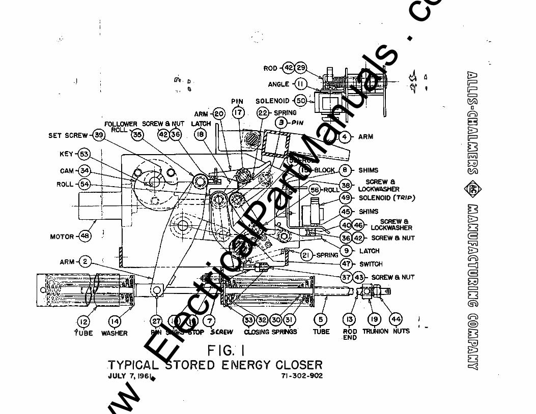
�ed-energ:r closer is an operator usin& compressed ··apri.Iigs to -close · a o�t breaker •.. A meto� compresses the aprings.thrOugn·a gear redtioti�, _cam. and latpl\=Lng qstem. Energi!:ln8 the spring release coll operates the latch to release the chuged e'prin&s and close the break�. ·
j.2 OHA�Dm THE· SPRiNGS A motor and gear ttnit (1-49) rotates. -(,� (1-34) ·which drives· follower roll (l-3;). Arm (1-2) rotates clockwise compressing'Closing sp�s (1-30),
·When springs are charged, l.&tch (+-18) falls behind roll (1-54) ho�' . the spri�s charged. When cam "{;1..:.34) 'clears the f'ollowe!" rQll.' (1-3;) oDJ¥
the latch (1-18) holds the springs "oharg�, and the opere,.tor is.· re&d7 .to . close the breakat". ·
·A Chargin;g. handle is furni�hed to charge the closing sp�ngs �ua.J4". . Opel1 the control power oircuit m:i engage the charging h4ndl.e with rthe
· couplins on the front of the motor (l-48). The epr:lngs ... SJ:e �ed b;r a ooui'lterclooladse rotation of' the handle, -Full spring o o mpree"sion ldll tie . reali.i� � an audi�le snap as roll (��;4) d.rop·a back on latch (1-l.$) ·w.en cam .(1-34) clears followez:' roll (1-35). Rotate handle two �ditional t-qma to insure cam has sufficient� cleared foll�wer �u. �e �eo
·.til· CUlSING THE)mJtM9! • . t i .
!nerP,Iin& the spring �r.aleaae ·coil (aolenoid)(l-S.O) rota�es arm· (l-20) � latoh (1-l.S) releasing aloains- epririga. ·ne olo� aprii3ga ro�ate am:
' (1-2.) vhioh" drives roll- (1-54} against roll (�-s;) thereb)r oloaing" breakero o c . .
·'lh�br,eaker can .b�. olosed manu.al.l7 by' puJ Jing l.aJQ"arc:t".�l-42) 1:3hieh �-t(j)s · · -&5,: {1•20) as _above� I •
• •
..; ' ...
·J·lt MANUAlS -SLOW CLOsiNG THE BlKER j • • • I I .. • '
I ·, •
. • I . Man� sloi:r closing the breaker is accOJiiplished b;r·�. charging the
. springs as described in section .3. 2 except,. tliat the "ohargi� .h�dle:-is rot.ated onlJr until the trip lAtch (1-9) drops in front of roll (1-56).
.• I •
� � I • .. • •
• •' • •
-- · Check· to see that- cam (1-34)is engaged-with fol.lolfer-roll--(l-.35), ... ·. � -ca.m
h&s 'been rotated too far and clears follower roll, merelJ" crank handle counterclockwise agairi. tmtil cam. is engaged with follower ron�
. ..
www . El
ectric
alPar
tMan
uals
. com

www . El
ectric
alPar
tMan
uals
. com

· ..
),.-4. ( CON'fiiiJED) . . , · : .. . . ,
.· . ., !he breaker can nol1 be closed w sl.olt-q · tlirzd.Dg · chargiq h&Ddl,.e· oloolnr.lse 'dlUe � "Second man �. �ol.diDg diaengqed. the ratChet and . paul (rear .. 9! . breaker).·lautu· • ou �· It latCh (l-18) :l:a ag&39d: utth -t�llol18i: lf.U �-3�.h �� u1:ll 'be. naoes�ar.r to � ·pull'· and hOld -laiv.� d.11rl.D&-first :
· tw or three :rOtaticma (c�G!Qladse) of haDdle. . . · · \
CA.Gimss Pm. wiwm. 6NLY .- cAM {1-34> ·IS ElfGAGEJ) m-s !'� BOU. (l-35l DtmlllG. MAHU.AL .st.l:f4 CLOSE 0'1 - ·BREAKER.
.
I ' fhe breaker ii ful.lT closed �en arm (1-2) is against atop (1-16).
·----·-.. -- . - --��----
. -
www . El
ectric
alPar
tMan
uals
. com

www . El
ectric
alPar
tMan
uals
. com

lt,.l GENERAL I
PARr 4 - ADJUSTMENTS .)
<Z ... I -��aker has· be.en completely set up, adjusted and tested at the .factoey. H�g · adjustment.s or fastenings mq be changed or become lt;>osened duriflg shipment,· storage or installatibn and should be cheakec1 and corrected, it necessary, .. hefore breaker is operated electrically. ManUal operation of breaker should be used for prel im1nar,y operation to see that all parts are free and work amoothly. The bushings and other insulating ·parts shcn:Ud be inspected to see that they are clean and smooth . (po nrit dress Silver surfaces .. ) Bemaval of all phase barriers and removal or· tilting of aro chute assemblies gives acc�ss to breaker for checking adjustments.
'l'he paragraphs .i.mmedia.te}J" following give the proper adjustments Bnd·me:thods of maldng same On the Allis-:Chalniers RUPTAIR lli Magnetic P6wer Circuit Breaker. · Adjustment values are a.ll .listed in· Appendix B attached. Note reference method - Appendix B-1 indic&,tes item ll in Appendix B.
4,'2 �- ,1-2)' Add or remove a1p.m8 (1-10) so that lllhen arm (1-2) is in discharted position, th!' clearance l;>etwee� follow-er roll (1-.35) and the small.EJst radius of cam
· · {1-.34) is l/11 t '1/32. · · . ·
-lt�l . 1mOR. AC'III:JA1'I(D StJI'l'CH . . •. . � . . .. ' . . . . . . . . -
the motor aotttatian Bldteh · {not Qb.own) is ·located behind the ·lower end of arm (1·2). 1he switch shoUld 'open when tip of'cam (1-34) is 100 to 1s0 above pc)sition sho-wn in' �gure 1. Proper adjustment is optained as follows: ld.th closing springs charged arid -.latched; remove Switch· and- screlf one nut alh ilie .1181' dow to. base or stud. - Inse� switch in brae�tJ starJ;..· -�,eoond nutb. --Pull switch forward with second- nut until contacts snap open. TUrn setond. nut. dcn:m. � additional one-half turn. Tighten. �st nut . against_ bracket to lock in :Position.
·
. ! -4•4 MOTOR- CUTOFF SWITal
. . .. The D10tor eutot! switch CJlot sholfll) is located below spec;tal cam ad.jacemo to main � (1-.34) • . The switch. Should open loben cam (1-34) is 1-n 'poSit.tim sh<?VJl in Figure 1. .Proper adjustment is made as follows:· Positipn C&UL . (1-34) as '-shown ·in F�" 1.� Remove switch and insta.U as de scribed in Section ;.3. -
4. 5 CLOSING SPRINGS . ..
\f,tth sprh,gs ·d.isch�ed. there-should be ·3/S t 1/8 clearance };)etween·trunion (1-19)
. and spring washer.. Adjustment is made by moving nuts (l-44). ' .
www . El
ectric
alPar
tMan
uals
. com

www . El
ectric
alPar
tMan
uals
. com

.. . t11th .Spr:1ngs chal-ged aDd breake:r- cipen,·. clearance bet'W'een trip latch (l-9). a:ad.J;'OU (1-56) should be l/.32 t jJ64. Adjustment ia Ude by adju.sti.Dg sorev (1.;.7). ·
· �� '
4o7 tm;P WC!l' BITE Boll (1-56) should engage trip latch (l-9) ·s/32 ± 1/32 :f'rom bott�m edgqjl o:f' latch face. Ad.justmeut iB made bJ' BerEnt, (l-36).
ltlen brealcsr ·ia in closed position with roll (l-55) _againat block. (J.c.lS),· center o:f' main toggle .roll .(1-SS) should be l/1+ :t 1/I.&· behcmci line of
· ·cimtera ot latoh :roll (1.-56) and pin (l-3),_ Adjustment is made by add1• Gl" remov1Dg shims (l...S). .
·.' ; .
It, 9 CIOSING .
SPBING tA.TCH Bm
BOll: (;t•54) should q&ge latch (1-18) 5/32 t l/.32 !rom bottom edgs of. l.&tch .:race. Adjustlneut is male by screw {1-42 ).. '
\tlen closing spri.Dge are cha.rged and breaker is_ o�n, tb.e clearance between toggle rolls (l-54}_ and (l-55} should be 1/8 t· l/32. Adjustment is made by changing eftect1ve le»&f;h ·or piston' in 'both dash pots (21-.31). Thia ia done by looseniilg locld.Dg nuts on rod ends (21-48) and ti:lrning pistons to desdrad l�h.
·
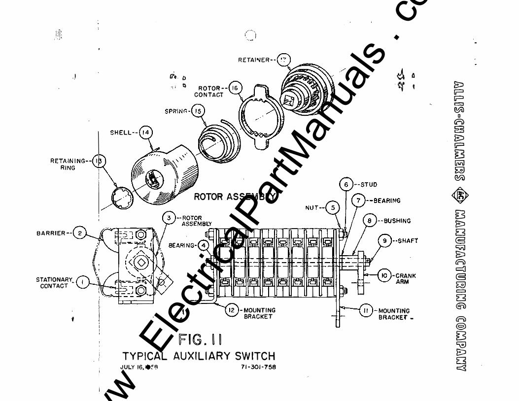
The auil.iary' switch, located a.t the rear o:t the breaker,: h� been .adjusted a.t the tacto17 and should not normally require further adjustment;. Hottever, before the breaker 1s placed 1B service a check ehoulc! be·made to see that the crank· arm (U-10) throws approximately equal diatances on either �de o:( a verticai center line. The adjW!Itment for throw o! crank �is made
·,
,..--.., r •
\,__ :..:'
b7 positioning the c1evis on the anxilia.ry switch connecting rod. After correct adjustment is· ma:le, make sure all i'astenings and locknut.s are secure •
. Ea.eh ·rotor·(ll-3}-can·be -adjusted individ'llal.ly in steps o! ).5 degr.E�ea .. me� ___ ____ _
·by pressing the conta.ct to one side against the sprillg and �tatins it l:d.tbin ita insulated :zootor housing until it snaps into the desired position.. Ant. ch"iihges made on this switch should be done c aref'u.l.l¥,
. p
www . El
ectric
alPar
tMan
uals
. com

www . El
ectric
alPar
tMan
uals
. com

. . !t�� ..
_ �c�: �<zl �m. A� • J fba foot. l�r· (21-20) operates the interlock j>llUtger .(2]. ... 18) � nll. as·
. the trip la.tch, 'moter cutoff' mtch and closing spring -�taho, .Depreeaiq thG=ZJ.fivr opens_ the ao_tor circuit, discharges th, cloaiDg apr!.nge, bdps · �rand raises pllinger (21-18)· Stl!!icient]J to ".lease �e breaker . �- it to be 1IO'Yed il1 the cubic;Le. 'fh\". interlock .. is 11;1. proper adjuatmant 't"Jhen the p:bulger .(21-18) is l-3/4 t l/16 abOve. tha ·noor0 mad. aallees trlppbg o! brealcaza ·contacts llhen it is ·raised to not· more thea ·
2-l/16 abo're t.he. tJDor. ·'lhe le.tah trlp� · rod ueooi&ted 111-th the f� lQVQI" should 'b8 oltaar of the trip latch (1-9) b;y 'l/32 to l/16.
. . . .
til& Q�AC'l-�1.69. ��.�. �Q OODtaots a� aD 1ntg�al part ot tne buBhiq ass.,uara -� mra oa.rO=o flll.lT &lip� mt.h tha uppar Ul4 � lniahins� bcafo�·-sbi� a·no· �or adj'IIBtmsrlt ahoalA normal.J¥'ba ZWCiiiSS&%7o Obw fez> p-GI)QZ' oont�Cit eJ.:Sgmru;mt d·D at �Q � t�b fo�>·liO'fizlg cOntact. stro� b7 ohQ� .
.. d.iSezasien J!l> Viw •AA•" Plio 23� ·betW<m ·oaat&at. �� .(2JoS3) ·e.d �to ::(24-lO)D. em each �a of lmeMnlt) top anc1 bOttom ot acla phasG SQPU'�t�o -It is ·�t. n�es� that oom.aots touch Edllalt�oual.T on all t.hztQa �QOcs
'\ . .. .
-··Us� this -dbwnsian is fOUDd to be l/16 :1: ·J./64 at all fo'Ql" points iD. o.. pbaaQ, botb. the alipamst. .of tb.e coutacte �the stroke -of tha � · cs.oataot of that .ph&sGI are oorreot-o .
, . . I l . If iOia . d.!M.aion is fouu4 �o })$ ctUferm t.baa l/l6. ± l/64 .. bu�. al% � . :I.D __ � .. phase aeaBUM l21thin l/32 or each �ar" ·it is ·neaesa&J::r ··to �\Wt
· tbe�reke of the � oont�ct of that phase: (�e4i'��ot1.on 4ol6),; : If · ·. ·
this d1mana�on is fl.ot witldn tolerance, alld: thera 1i a dif'!eHiiO-e ot: � 1/32 aiaong th• foar Jl.8aaurements ,in & phue, it is neceaa&1'7 to,._'ftrst, ·
· ad�U,t. the oontaGt. aHgnment (see .Se.�iOn 4ol5)1 8Dd tha the stroke of. the� oantaat (sea -Se.otion 4-c.lS')o ·
·�� '
www . El
ectric
alPar
tMan
uals
. com

www . El
ectric
alPar
tMan
uals
. com

ltel5 ADJUSTMEm' FOR OONTACT J.L!moo:NT {Cont.) , rn the event that this exact dinvmsion and tolerance cannot be obtained, m.O'V'e:zbl:gcks (.24-8) and (24-13) so that a.ll f'our dimensions c in a phase are td.thin 1/32 of each other. Pontact alignment in this phase will .then be� �per adjuetment. - •
Care JllWit be exercised in adju.stiug contact alignment to retain bloc.b (241.CS) and {24-13) .t'irlJicy' against stops on stud..
9:•1:2 ADJUSTMENT FOR Sl'OOKE ' '
Thia adjustment is accomplished b,y lengthening or shortening· effective le.ngtb o! link {21-47) to bring dimension c., View "AA", Figure· 23� to 1/16 t l/64. Open breakerJ screw nuts on bottom of link (21-47) on �· off · stud as required to bring this dimension to witlrln tolerance in all fO\lr measurements ·1n the Phase (see Section 4,14). Tighten both' nut'l before attspt;ing to close breake:r:' to check adjustment, The stroke should. be adjusted in each phase indi�uall,y.
�17 Com'Acrl t.pp (Fig, 23) Ccnltac\ lead it adjusted on bre!kers in the factory and should nt:rmalJ1' -d i'equire taz.tber adjustment. It ·should, however, be checked. on eaoh ]flase separately !W! on.l;y with contact alignment on the phaee in oorreot a.cl,Jutmens.. ·
In order tb prepare breaker for contact l.ea.d check and adjustina, be sure that breaker is open and disconnect the movable contact from operator link (21-41) by removing pin (21-46) and. two spacers (21-45). Bring movable· a.rci� contact (25-.3) so that it just· touches the stationa.rt · ar� -contact (24'l!+! as shown in Pig� .23, View "AA", (Arcing Contacts Enga.g:tng). · lfeu1uoe ��on � �e .23, �e shortest �ap between the .tw terti&r;r �MD
· az:ASdimensionlz. (View "!A•, Figure 23},-the shorlest gap bet'We$1 the JiaiD ·
aontaa\s. · DJ.m.eDsion a shoul.d be 5/32 -40, -l./32 and dimension b abotll.d = ii/J.6 +l/16. -l/JZ. - -
U the dimentdo1UI a and b are not correctl remove one roll piu i'l"Olll uch p-late {24-10), loosen eight screws (24-22J. Insert a spacer 5/J� +o9�1/32 tbiek bet�n the terti� contacts, and a.P,Ply a. C-clamp bearing on rear o! block (24_g) and front of movable eontact (2.5-J). 'l':ighten C-elam.p to obtain· dimensions b. Wl.th contacts· held in this poSition, move two plattts .. {24-10) back· so that pins (24-16) are touching leading end of'. Jll&te slots. �ten eight· ·screws- (24-22) dr.fll aru1· insert pin· -to#·retJain ad-jU&tment... BemOY.e spacer, remove e-:c1amp, ani reconnect movable contact to link (21-4�) •
....
r ·
www . El
ectric
alPar
tMan
uals
. com

www . El
ectric
alPar
tMan
uals
. com

PART 5 - MAINTENANCE
5.1 GENPRAL Safety of the operator and continuit y of electric service of loads c-o:ni'Rcad to circuit breakers are dependent upon proper operation ot .tiKi br�. In order to keep circuit breakers in proper order, it i8 • re�ded that a routine service inspection should be made at silt month or 2000 operation intervalB, whichever comes first. The actual aervi� interval and the amount of servicing required will usually be determ1De4 by the partiC\llar conditions at the installation and rill be intl.uGmCQd by liluch thii13s aa the ·mma'bar of ·operations, number of fault �tenuptiono, cleanlinolil& of the equipmtant and pe.gt gxperience with the equiJBQDto
·
Servicill3 ill 'usU&llr int�nded to cover adjusting, cleaning, lubrioatill641 t!Ghtellin3, :tn.sp3cticm, test, etco A permment record is usually cleo:lito.l>lo and gboald list fo� each serial aumbGr the date, OP,eration countGr rQa�� �Qft.GII"&l condition ot equipment and wrk done b7 oervicemano .
BQ ou�� �hat �he breaker lll1d its mechwam ·is disccmnectecl · !ram�·-oUoloctric powr and that thea 'breaker is in the open position .})afore OAY mintenanclil b attaDptedo
�ga CONTACTS
IJUJpece all contacts fro�aquGD.tly, de�nding on lHIVerity of liUarviogo lopla.oo ,badlr pitted or burned contacta before tha7 are damaged to such an <mtGD.t m1 to caur.1e improprar operation of thi breaker.
5, 3 BARRIIR Si'.ACKS
The barrier .stacks - are fragile and should be handled caref'ully. The barrier stacks should be inspected for erosion of the plates in the area£! of tli'aCSlots. The stacks should be replaced wen a milky glaze is �"b!lerved on t€e ·!'Ill length of .the edges of most of the slots, .They should b!il UkQco rise replaced if plates are broken or cracked. �en cleaning the breaker and cubicle, inspect for pieces of barrier stack refractory material tihich vould obviously indicate breakage.
514 BREAKliR TIMING
Check the contact a djustment and breaker timing, also check adjustments of auxiliary equipment and see that it fwtctions properly, A comparison of breaker timi.b.g -at- any- period of maintenance nth that--taken wen the breaker was new vill ilmnediately indicate a condition of maladjustment or friction should the timing vaey more than 1/2 cycles on opening or 2 cycles on clos-ing with the same coils. ·
_ r .
www . El
ectric
alPar
tMan
uals
. com

www . El
ectric
alPar
tMan
uals
. com

ia5 �CATION l;Jl.brication' is O:f the U't.IItOSt importance and 8. special effort ShOuld be made to assure that all moving parts are kept clean and properly lubricated at fu-tillles. ·The disconnect hlnge joint and the solenoid armature t" ��ed with microtine dr;y·graphite. Graphite ehoul.d.be_ rubbeq__i.P well � al1 excess carefu.l.l7 remoYed. CAUTION t GBAPH:rfE MOST § KEPT OFF INSULATION tJHOER· PENALTY OF REPI.A.CE-
MERT. AS rr ·cANNar BE sATISFACTOR.II.Y REMOVED. · ' · .
.BeariJ:2& Pins &JJ!. other mo'Ving parts should be llght:q lu.:brica.ted nth a light tilln or 11Aero blbriplatett or equal. Needle Bearings will in general not reqtrlre frequent lubrication, but care should bit taken to· prevent ent!'&Bce. ot dirt. and .f'oreign material during maintenance wrk. Mating surfaces o.f' main·� arcing·contacts should not be lUbricated •
. ;., 6 XADrENA'NCE GUIDE (
. Check �stments in Sections 4.;! through 4.5, inc:W.sive, as wll as ·Sections 4�1.3 and 4-�14 at ea.cli routine ·inspection. The other adjustments &re listed to assist repairing. a malfunctioning breaker.
� .. . IS ,.
/,... . . � J 'l.,r ..
www . El
ectric
alPar
tMan
uals
. com

www . El
ectric
alPar
tMan
uals
. com

\
PART 6 - RfPLAC�T PARTS
6.1 HOW TO ORDER c;:z ....
bb.en orderillg replacement parts, it is very important to give complet� in� on. This information should include: - -
(1) (2) (3) (4) (5)
(6) (7) (8) (9)
Breaker serial number
Number of pieces required
Reference number IJiatruction book number
Description of part (Use instructi�) bOok . · Vhere possible
descriptions
Rated voltage of all 1110tors 1 relays aud coils ordered ' . .
Rated amperes of all motors, re�ya and coilo ordered
Rated voltago of hzoeaker
Rated 811lperes of ·breaker
The breaker serial number is necessary to determine the correct identitr of a part; without thi£1 serial IIWilber, Allis..Chalmara Mtg, Co.o c81Ulot bca. SUN of the _correct ·identity of the desired parto.
·
If any doubt exists as to the instruction book reference or the descripd.oa a dimensional sketch of the desired part will help to properly identify ito
. . ---�·- ... -
www . El
ectric
alPar
tMan
uals
. com

www . El
ectric
alPar
tMan
uals
. com

. '
622 BECOMMENDED .SPAt£ PARI'S LISr (BWZ-6601) I ' - , It is recoml!lElnded that .sufficient parts be carri.ed iil 8 i;oCk ·to eriable
operators of, circuit breakers to replace without dela;r � �rn, broken, or damigecf" parts. A list o! recommended spare parte f'ollow and is &rr8f«ed ��ta.t.e ehOos:lng the correct parts for the breakers involTeci.&, _ftJo colU'iliris em this list give the ql18.lltities l'eocmmended tor an instal.J.a.tionot one to f.iye breakers and for an installation of five or more breakers.
Recommend tor stock 1-S 5 or more
Ret', Wo, Description J
DraJ!!.M No. ' Breakers Breakers 21-3 Contact Finger Ass��
1200 Amps 71-201-738-501 2 6 2000 Amps 71-201-458-501 2 6 .3000 Amps 71-240-442-501 2 6
1-50 Solenoid (spring release) 230V DC l'S-549-204 1" 1
48V DC W-549-108 1 1 Y Belq 230V DC W-541-307 1 l
48V DC W-541-309 1; 1
1-49 Solenoid (trip) 230V DC ll-549-204 1 l 413V DC W-549-108 1 1
21-25 Berrier Stack 71-302-7?6-;at 2 6
24-.3 Contact Finger (SI:atialaey') 'll-lll-45�501 10 30
24�4 Arcing Contact (sta.tional"Y) 71-113-148-501 3 3 25-:9 a Contact (Jbving) 71.:.207-476-504 3 3 :zs:.§
.. 1> ,. Washer 71-lll-446-001 4 12 26--; 'fransf'er Stack 71-207-489-502 3 3
-- -- . - , -
-
-·,
( . ' ' -
www . El
ectric
alPar
tMan
uals
. com

www . El
ectric
alPar
tMan
uals
. com
• I
Before removing 1J1l7 part, observe. its· 1\mation and adjustment. B;y so doiDg, · it ·�a ..as� pC;sSible to avoid s:q apprebiable amount of adjustment �k
after the installatioa of the replacemeJI\i pSl"t. · •
�U' CAUTION • BErOB. m:MOVING ANI PARr 1 MAKE SURE THAT THE ��
AND l'fs· OPERATING MEOHANISM !IS DISCONNECTED FROM ALL ELl!:CTRIC POWER AND THAT THIS BREAKER IS lN THE OPEN l'OSIT!OU. . I
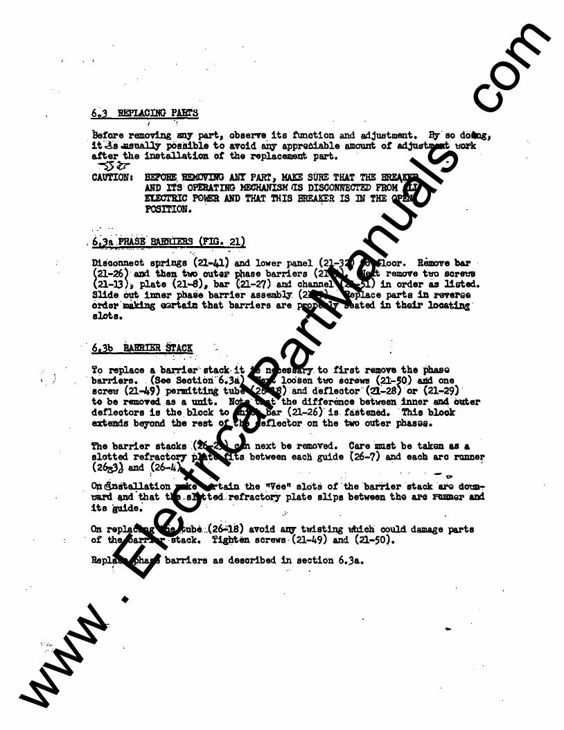
I w& �msi BARRIEBs crm. 21> . ,_ s 5: ..... ! • -. • • • . • • • .
Diaoonneot springs ·.C2l-41) and lover panel (21-32) to noor. Remove bar ·
(21-26)· aM. then two outGi' Pllase barriers (21-5). Hext remove tw screw (21-13) ;p plate (21-8), bar (21-27) and channel (21-51) in order as listed. Slide � 1Dner phase barrier assembly. (21-9). · Replace parts in reverse o:rdcn'mak1ng cwaria:f.n that barriers are proper:q seated in their looati.Dg· slots.
·
.
6,3b iwmmR STACK i'o replace. a b�er'· stack- it. is necessary. to first remove the Pha&Q
· barriers • . (See Seotitn:i"6�3a) Baxt lo6sen tw &crewe (21:..50) &lid one scre11 (21-49) permtt!Dg tube· (2�18) ·and d·eneotor·· (�:..28) ··or· (21-29) · to be removed as a unit. Uot·e· that the difference betweel\ inner aD4 . outer deneotors is the. block to vhich b&l" (21-26 )• is tastened, . rue bloCk exteDds bqond. the rest. of the defiector on the tvo outer phas!iij.
'fhe barrier stacks ·.(26-23) can next be removed. Care ·mst. be taltEID as a ·
slotted retracto� plate fits between each guide (26-7) and each arc runner (26zs3l and :(26-4). ·
· · ' . . . 0
OJt&ataJ.latiou make ·certa1D the nvee" slots o! 'the 'batTier ·stack·� cl� mrd -.ncfthat the.slotited.:retractoey plate slips between the 81'0 I'Uiler aDd its guide� · · · · :· . . . On replacing tl:ie. :t;ulu!l.:.(2�18) avoid 8Zf3' tld.sting l4lich could damage parts
· of the barrier ·Btacka fig}lten screws.· (21-49) and (21-50). ·
Replace ph&�e barriers as described in section 6.3a • • ·. • ' .
-
www . El
ectric
alPar
tMan
uals
. com

www . El
ectric
alPar
tMan
uals
. com
> • ,_:•
MOTOR
. )
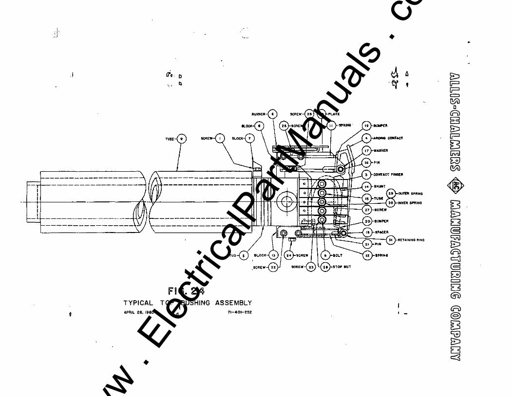
fUBE WASHER
(i'q. 0 . .,. 4
FIG.· I .TYPICAL STOR.ED ENERGY CLOSER JULY 7,1961 71-302-902
� a . �� '
ARM
SHIMS
SCREW 8 LOOKWASHER SOLENOID (TQJP)
SCREWS LOCKWASHER
SCREW 8 NUT
I -
�
� !? I? c:::J C0i)
c A 8 � I? [5 � � <!:0)
� [5 � E3 C5 CVil � A c:3 @ E3 c:::J D <§l) A @> � � ES E3 r::::s
www . El
ectric
alPar
tMan
uals
. com

www . El
ectric
alPar
tMan
uals
. com
. �: ����
,,1
RETAINING--{ I RING
BARRIER --l 2
STATIONARY_ CONTACT
f
SHELL--
' �- 0 ,l � ROTOR-
CONTA�
( ... . 1 ··-
RETAI"-JER--
ROTOR ASSEMBLY
a
Fl G. � �
-MOUNTING BRACKET
TYPICAL AUXILIARY SWITCH JULY 16,19:8 71-301-758
/ � 0 ·� .
-CRANK ARM
II J- MOUNTING BRACKE'f-
g:, p p r:::::::J (01)
D ((=)) g E;:l I? [3 [iVlJ E3 (0U
� [5 � 8 8 CVJ E::l A � @ � c:::::;:J 8 @) A @) [S � � E3 c::::s
www . El
ectric
alPar
tMan
uals
. com

www . El
ectric
alPar
tMan
uals
. com

, . :I'
;(, ......... ,\
.J U�J7f\ 84RRIEI'I. A.SS'Y. (tiVNER) . � .)V • E::J
OEF£ECTDR (tNWER.) ·� 7 I ..... p p c:::::J
... ._<�>. 1--./ I / � II_ (0i) - D G=;) 8 E:J
*' •»� I II �i'H.'P:'o.''>u G=J [3
'ANNEL -(61).- 1111 IIH I II II ·1111 - I I I! I 1111 I ! I ���Rj"" (PriJ
(L.fl.) E:3 ·CIJ�.$ � �.HJ
� D
SARRIER-{I!J'r I ''(j •l...,;""'� I --rl (.uJ-iiiOITIIII � 8 CViJ E::l
't MfiTAtT M - ....... j \.\ ;:::E 'L �J:tiN @ AUX. .SWIIt:ll-@-- (5 . . TR.IP �01'.1 G
RDO ENO LANYARP c:::::J
'"� .6A I G =ill-1 r ·FDDT LEIIER. � Oc � "'\..."'ff -·--c:J ' I iP tflrE"-U)CIC �«ilEASE l.':l V �OA5HPoT A f :1', ! � 4WIPEB4R t.e ' j "', 1 81 _ .•• -@J.�.cvNc;e� @>
GROf.IN()III(G 1 · ...._.... �
F"IN&ERS i:-,:1 � !FIG. 21 �
:� TYPICAL MAGNETIC BREAKER ASSEMBLY E3 Auo.ra, rear 1'1-8141 -see c::3·
www . El
ectric
alPar
tMan
uals
. com

www . El
ectric
alPar
tMan
uals
. com

.,1
------ �-----------
_____ j ___________ _
-----�-----------" , � , J l
_____ ...;..._ __________ _
VIEW 'A-A'
·' .
, __ ..,. .
�
F�G. 2� IBREA�ER LATCHEOI
TYPICAL STUD 8 SUPPORT ASSEMBLY MAY 9, 1960 71-401-2!9
� a -� q
TOP BUSHING (SEE FIG. 241
I..OWER BUSHING ISEE FIG. 2�11
SCREW
\.-• "4 4 }-BRACKET
r--., ' � I I MtEI!
VI£W 'A-A" (ARCING CONTACTS ENGAGING!
SJ p p c::::l �
D ({=1) B B:J p [5
. [jVi] � C!:0l
� [3 8J 8 C5 CVi1 E::J A � (5 � c::::l E3 G1) � @ [3 � 8:J D �
www . El
ectric
alPar
tMan
uals
. com

www . El
ectric
alPar
tMan
uals
. com
.·: •I:'
, ,
' TYPICAL APRIL 28, 19$0
(]'�. D . , , �
-------------
FIG. 24
'- ·-
STUO
TOP 1BUSHING ASSEMBLY Q 71-401-2�2
J. L\ -� '
DliTPt GPRINIJ INNER SPIIII:IO
RET.INING RINQ
� p [j=l c:::::J �
c A B E:J [j=l [S lNll � �
� [3 E:::J D @ CV\1 � A c::J @ G C=:J ES G)) A @) [5 ca � E5 c:::3
www . El
ectric
alPar
tMan
uals
. com

www . El
ectric
alPar
tMan
uals
. com
. . 1
�
·� i
\ e e } ---,---:-- --1 ·-r, ,_ _ _ _ _
1 I I 1 I I I 'I 1 I I I I I I I } / I
I
I I
I I I L.:..:IJa.t..-t.�-_,/ l
' �
;" ' ·.\ '1.·-�·
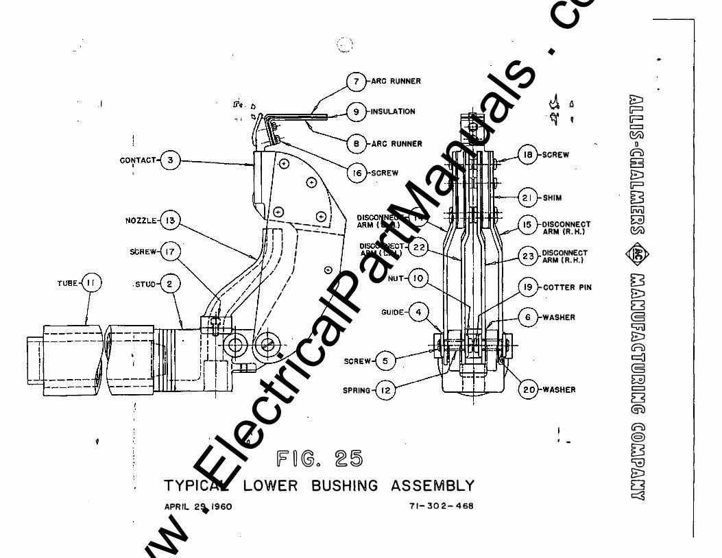
7 �ARC RUNNER
INSULATION
8 }-ARC RUNNER
SCREW
SPRING
� ij �o � � TYPI CAL LOWE R BUSH I N G AS S E M BLY APRIL 29, 1960 7 1- 3 0 2 - 4 68
� 0 . <r q
SCREW
SHIM
DISCONNECT ARM (R. H.}
DISCONNECT ARM ( R. H. )
COTTER PIN
WASHER
. -
E:J I? p c::::J �
D A g E::J p [3 liV\1 E3 �
� [5 t:J ES @ � � A � (5 � c::::J 8 @) A @) [S � � E3 c:::5
www . El
ectric
alPar
tMan
uals
. com

www . El
ectric
alPar
tMan
uals
. com
'· . . -·
<l -
--- , r----, I I I I I I I I I I I I L_J
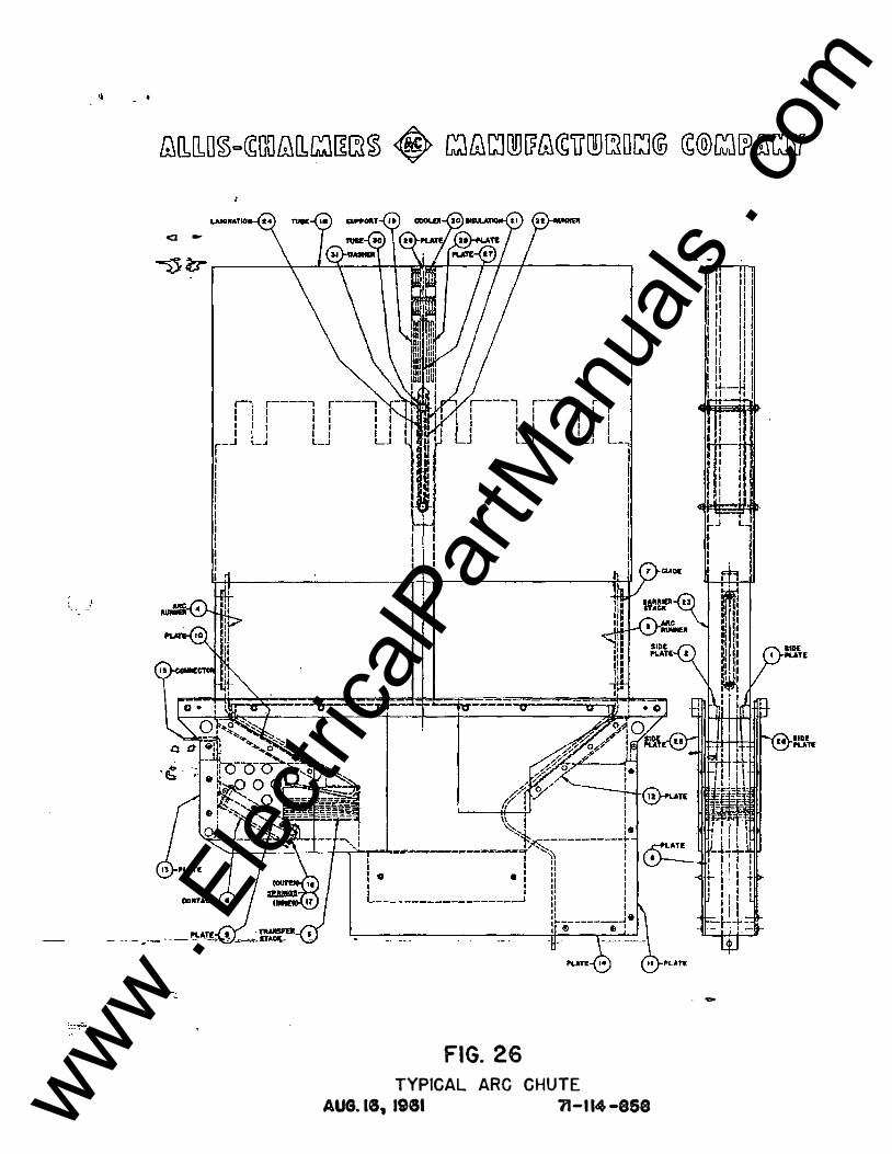
FIG. 26 TYPICAL ARC CHUTE
AUG. I8, 1981 11-1 14 -858
. -
www . El
ectric
alPar
tMan
uals
. com

www . El
ectric
alPar
tMan
uals
. com
II - •
}
<J -
Q C
"' ·-
- 1!::1 ,.
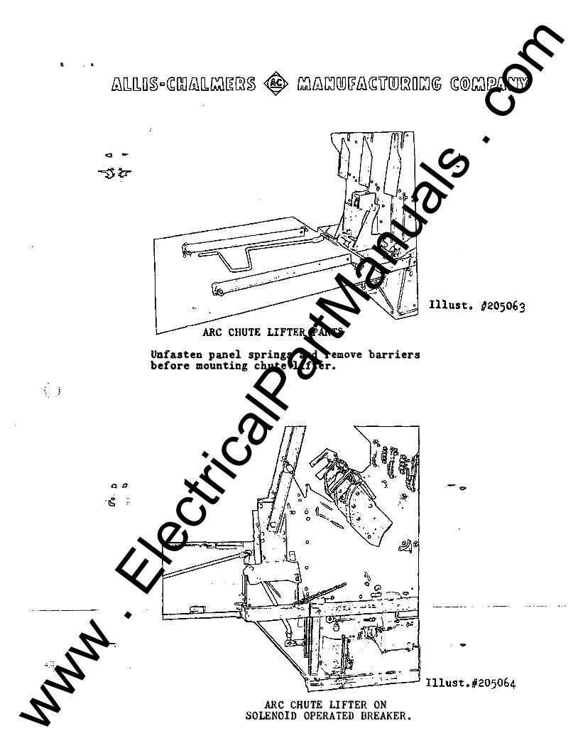
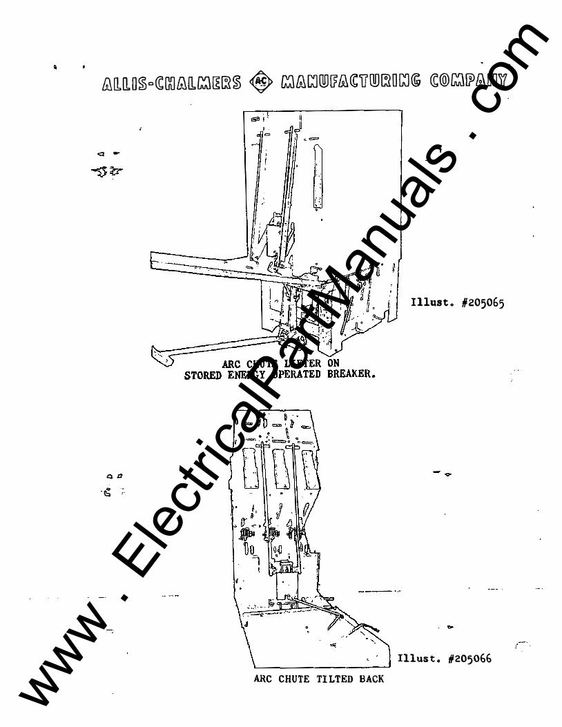
Unfasten panel springs and remove barriers before mounting chut� lifter.
ARC CHUTE LI FTER ON SOLENOID OPERATED BREAKER . www .
Elec
tricalP
artM
anua
ls . c
om

www . El
ectric
alPar
tMan
uals
. com
�
�[lJLO�o�[}{]t:;JQ.���� � �f;,lLJI]JlJ&CCUOD�OGJ@ �®�l?&Jr;Jl?
<l -
Q U 0 -- IS ,.
� .
I llus t . #205065
0
�------------� Illus t o #205066
ARC CHUTE TI LTED BACK www . El
ectric
alPar
tMan
uals
. com

www . El
ectric
alPar
tMan
uals
. com


![Installation Guide Brea™ Guía de instalación Toallero de Barra de … · 2018. 11. 26. · BTB-BR2* 18" [457mm] 24" [610mm] CLEANING INSTRUCTIONS: Use only a soft damp cloth to](https://static.fdocuments.fr/doc/165x107/60d4e8b3a2a1e85b7f1f1a33/installation-guide-breaa-gua-de-instalacin-toallero-de-barra-de-2018-11.jpg)