Validation de systèmes à vide pour le grand arrêt numéro 1...
26
Validation de systèmes à vide pour le grand arrêt numéro 1 du LHC Gregory CATTENOZ, CERN, TE-VSC group, on behalf of LHC Beam Vacuum section Journées thématiques : « Problématiques Ultravides d’aujourd’hui sur les installations complexes » Institut Néel CNRS, Grenoble, 1er et 2 Décembre 2014 .
Transcript of Validation de systèmes à vide pour le grand arrêt numéro 1...
Validation de systèmes à vide pour
le grand arrêt numéro 1 du LHC
Gregory CATTENOZ, CERN, TE-VSC group, on behalf of LHC Beam Vacuum section
Journées thématiques : « Problématiques Ultravides d’aujourd’hui sur les installations complexes »
Institut Néel CNRS, Grenoble, 1er et 2 Décembre 2014
.
Outline
• Introduction
• Presentation of the vacuum validation process
• LHC beam vacuum consideration
• 3 tests overview:
• Pump down
• Residual Gas Analysis
• Internal leak rate measure
• Example of the Totem roman pot detector
• Conclusion and outlook
CNRS, 1/12/2014 1
Introduction
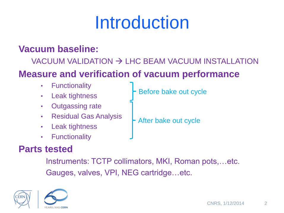
Vacuum baseline:
VACUUM VALIDATION LHC BEAM VACUUM INSTALLATION
Measure and verification of vacuum performance • Functionality
• Leak tightness
• Outgassing rate
• Residual Gas Analysis
• Leak tightness
• Functionality
Parts tested
Instruments: TCTP collimators, MKI, Roman pots,…etc.
Gauges, valves, VPI, NEG cartridge…etc.
2
Before bake out cycle
After bake out cycle
CNRS, 1/12/2014
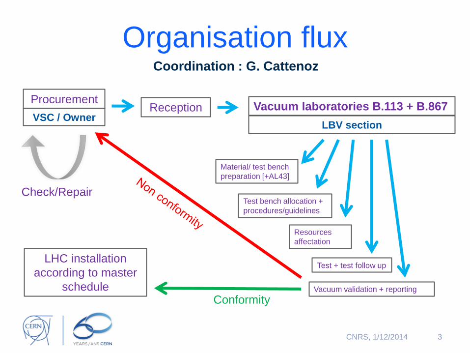
Organisation flux Coordination : G. Cattenoz
3
Reception Vacuum laboratories B.113 + B.867
Vacuum validation + reporting
Resources
affectation
Material/ test bench
preparation [+AL43]
Test bench allocation +
procedures/guidelines
Test + test follow up LHC installation
according to master
schedule
Procurement
Conformity
VSC / Owner
Check/Repair
LBV section
CNRS, 1/12/2014
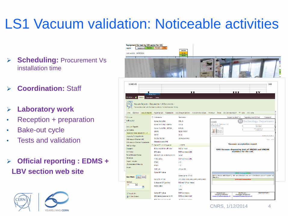
LS1 Vacuum validation: Noticeable activities
Scheduling: Procurement Vs
installation time
Coordination: Staff
Laboratory work
• Reception + preparation
• Bake-out cycle
• Tests and validation
Official reporting : EDMS +
LBV section web site
4 CNRS, 1/12/2014
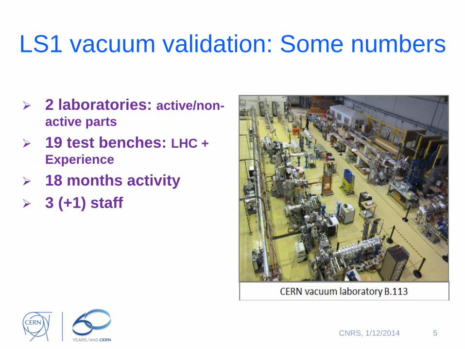
LS1 vacuum validation: Some numbers
2 laboratories: active/non-
active parts
19 test benches: LHC +
Experience
18 months activity
3 (+1) staff
5 CNRS, 1/12/2014
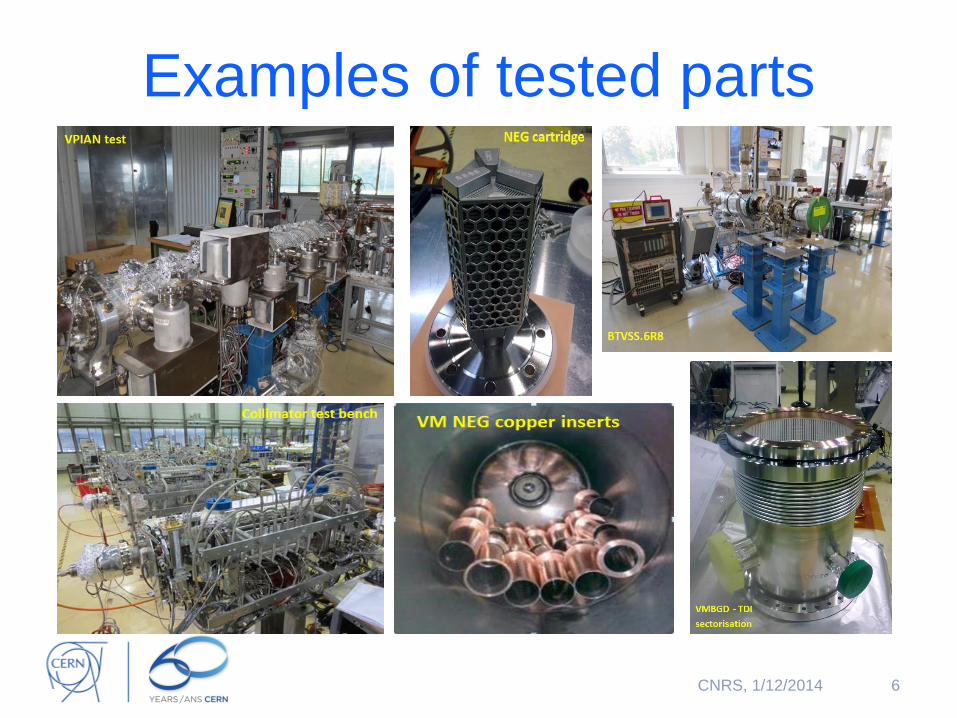
Examples of tested parts
6 CNRS, 1/12/2014
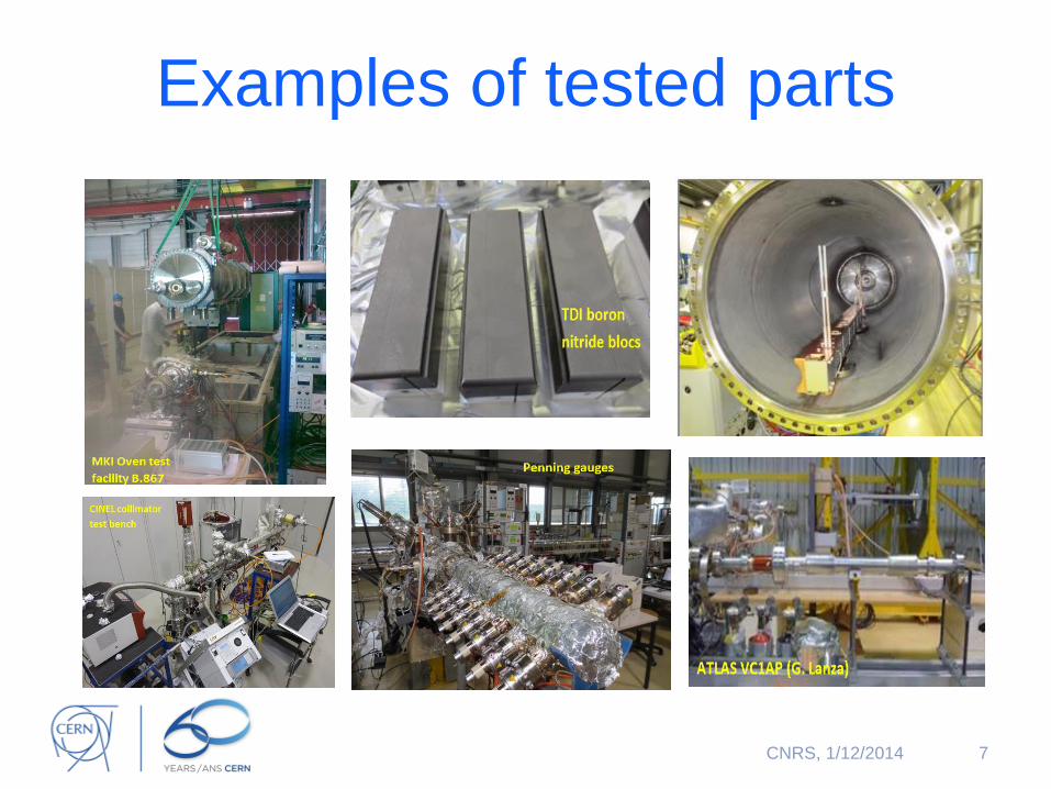
Examples of tested parts
7 CNRS, 1/12/2014
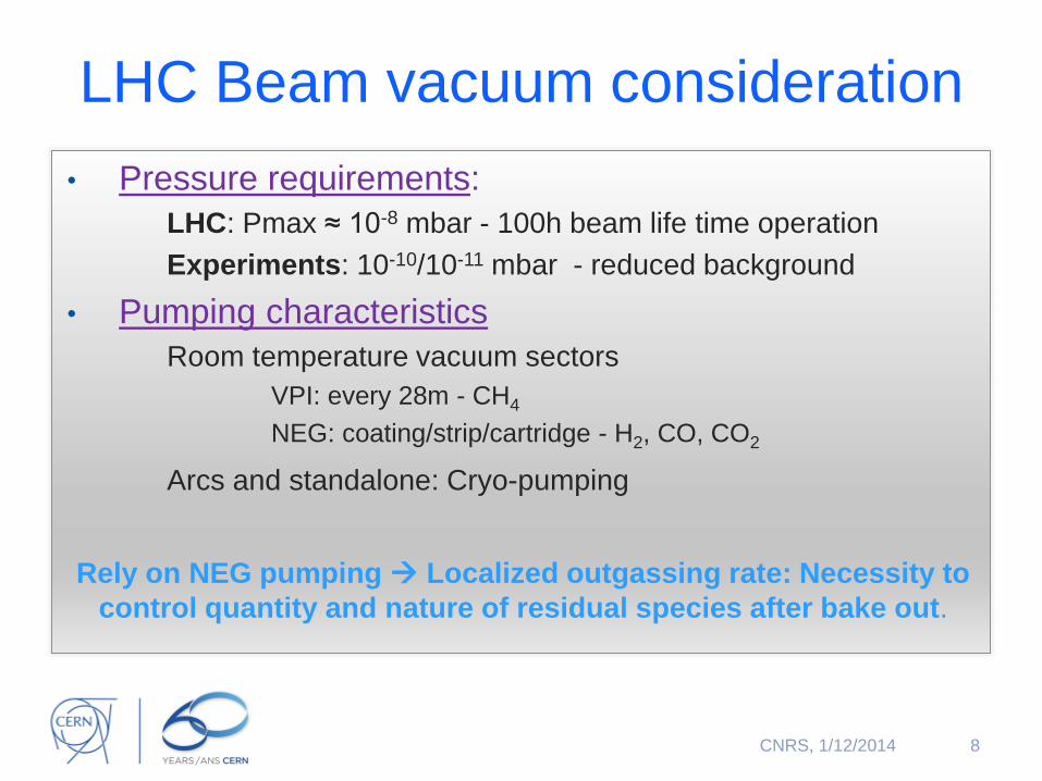
LHC Beam vacuum consideration
• Pressure requirements:
LHC: Pmax ≈ 10-8 mbar - 100h beam life time operation
Experiments: 10-10/10-11 mbar - reduced background
• Pumping characteristics
Room temperature vacuum sectors
VPI: every 28m - CH4
NEG: coating/strip/cartridge - H2, CO, CO2
Arcs and standalone: Cryo-pumping
Rely on NEG pumping Localized outgassing rate: Necessity to
control quantity and nature of residual species after bake out.
8 CNRS, 1/12/2014
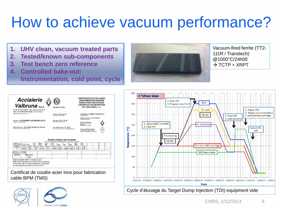
How to achieve vacuum performance?
9
1. UHV clean, vacuum treated parts
2. Tested/known sub-components
3. Test bench zero reference
4. Controlled bake-out:
Instrumentation, cold point, cycle
Vacuum-fired ferrite (TT2-
111R / Transtech)
@1000°C/24h00
TCTP + XRPT
CNRS, 1/12/2014
Certificat de coulée acier inox pour fabrication
cable BPM (TMS)
Cycle d’étuvage du Target Dump Injection (TDI) equipment vide
1. UHV clean, vacuum treated parts
2. Tested/known sub-components
3. Test bench zero reference
4. Controlled bake-out:
Instrumentation, cold point, cycle
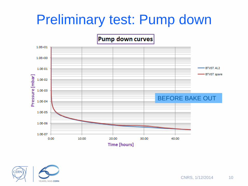
Preliminary test: Pump down
10 CNRS, 1/12/2014
BEFORE BAKE OUT
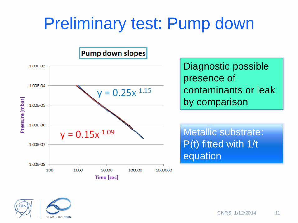
Preliminary test: Pump down
11 CNRS, 1/12/2014
Metallic substrate:
P(t) fitted with 1/t
equation
Diagnostic possible
presence of
contaminants or leak
by comparison
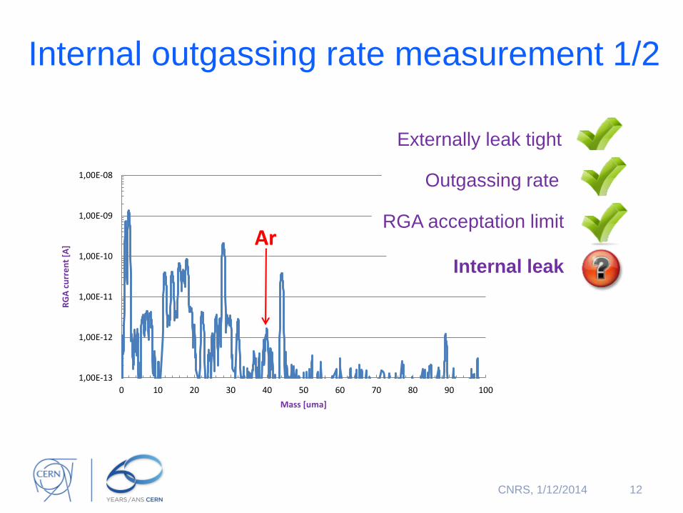
Internal outgassing rate measurement 1/2
12
1,00E-13
1,00E-12
1,00E-11
1,00E-10
1,00E-09
1,00E-08
0 10 20 30 40 50 60 70 80 90 100
RG
A c
urr
en
t [A
]
Mass [uma]
Ar
Externally leak tight
Outgassing rate
RGA acceptation limit
Internal leak
CNRS, 1/12/2014
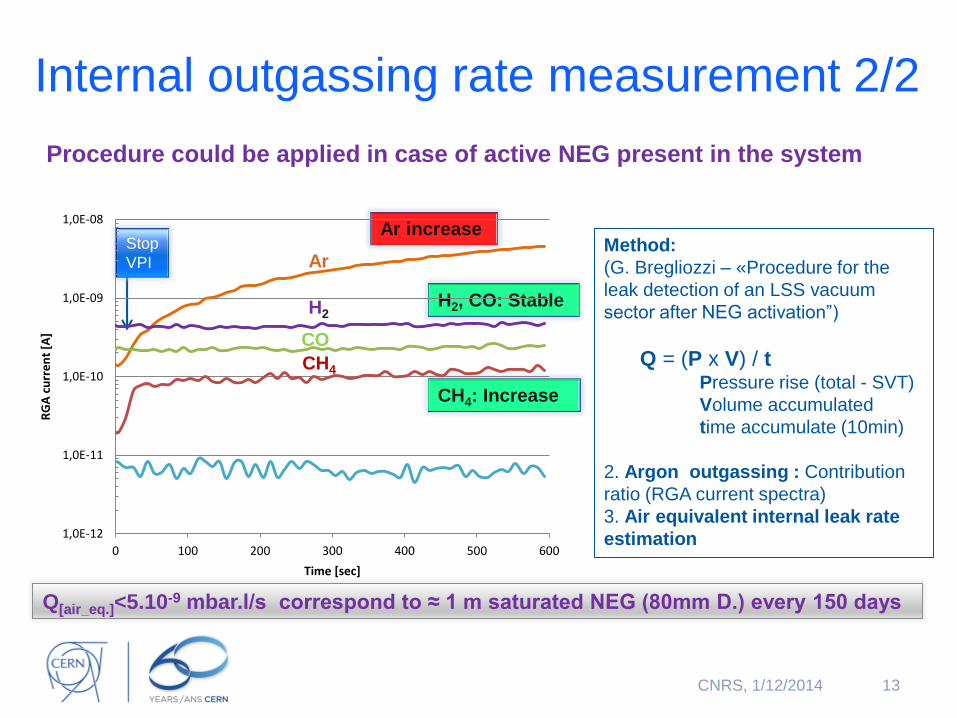
Internal outgassing rate measurement 2/2
Procedure could be applied in case of active NEG present in the system
13
H2, CO: Stable
CO
CH4
Ar Method:
(G. Bregliozzi – «Procedure for the
leak detection of an LSS vacuum
sector after NEG activation”)
Q = (P x V) / t Pressure rise (total - SVT)
Volume accumulated
time accumulate (10min)
2. Argon outgassing : Contribution
ratio (RGA current spectra)
3. Air equivalent internal leak rate
estimation
H2
Ar increase
Q[air_eq.]<5.10-9 mbar.l/s correspond to ≈ 1 m saturated NEG (80mm D.) every 150 days
Stop
VPI
CH4: Increase
1,0E-12
1,0E-11
1,0E-10
1,0E-09
1,0E-08
0 100 200 300 400 500 600
RG
A c
urr
en
t [A
]
Time [sec]
CNRS, 1/12/2014
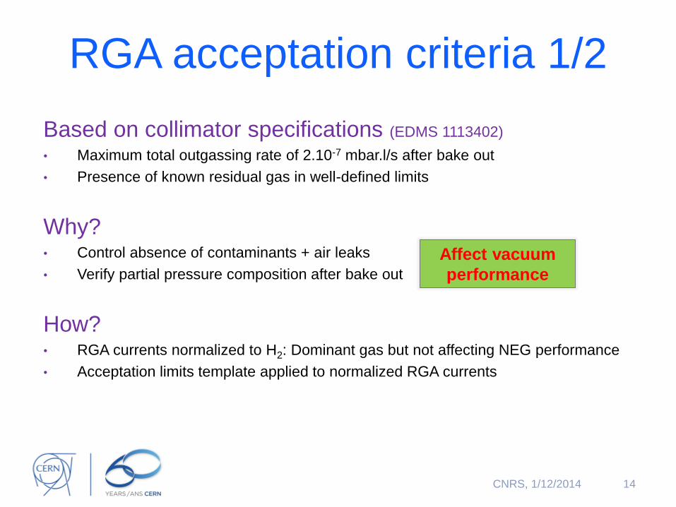
RGA acceptation criteria 1/2
Based on collimator specifications (EDMS 1113402)
• Maximum total outgassing rate of 2.10-7 mbar.l/s after bake out
• Presence of known residual gas in well-defined limits
Why? • Control absence of contaminants + air leaks
• Verify partial pressure composition after bake out
How? • RGA currents normalized to H2: Dominant gas but not affecting NEG performance
• Acceptation limits template applied to normalized RGA currents
14
Affect vacuum
performance
CNRS, 1/12/2014
0,01%
0,10%
1,00%
10,00%
100,00%
0 10 20 30 40 50 60 70 80 90 100
No
rma
lize
d c
urr
en
t va
lue
s
Mass [a.m.u.]
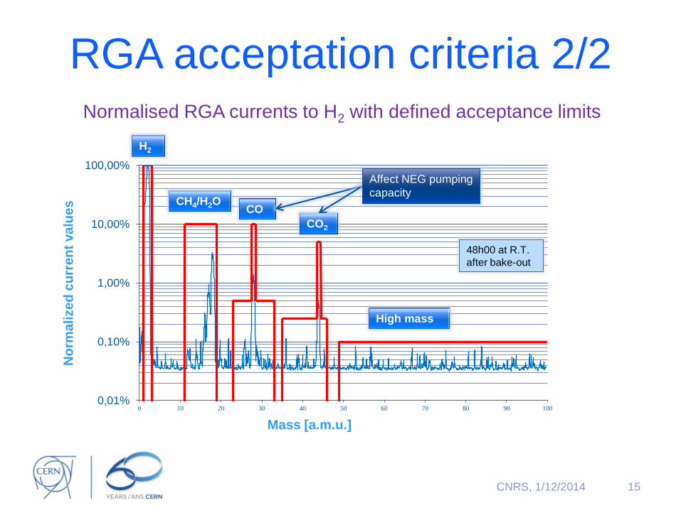
RGA acceptation criteria 2/2 Normalised RGA currents to H2 with defined acceptance limits
15
H2
CH4/H2O CO
CO2
Affect NEG pumping
capacity
High mass
48h00 at R.T.
after bake-out
CNRS, 1/12/2014
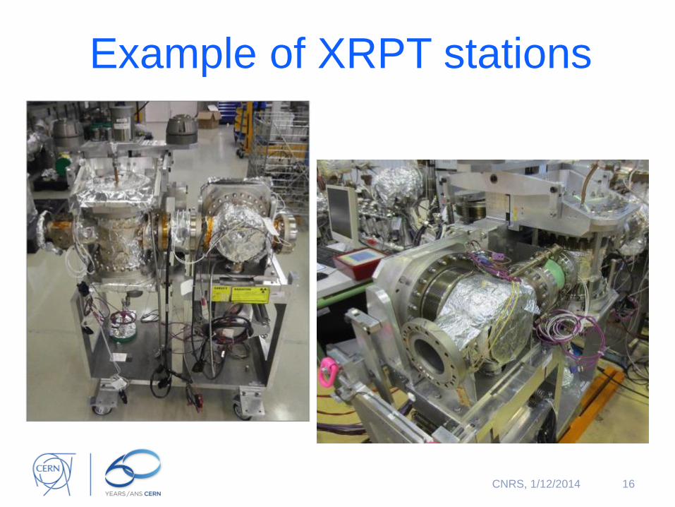
Example of XRPT stations
16 CNRS, 1/12/2014
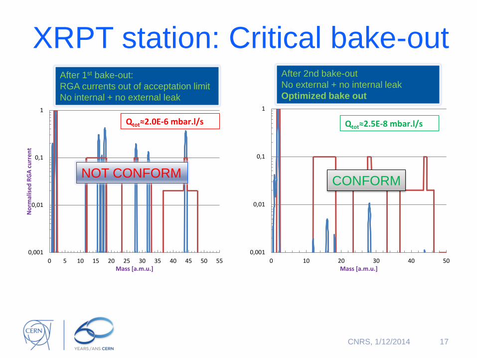
XRPT station: Critical bake-out
17
0,001
0,01
0,1
1
0 5 10 15 20 25 30 35 40 45 50 55
No
rmal
ise
d R
GA
cu
rre
nt
Mass [a.m.u.]
Qtot≈2.0E-6 mbar.l/s
After 1st bake-out:
RGA currents out of acceptation limit
No internal + no external leak
0,001
0,01
0,1
1
0 10 20 30 40 50Mass [a.m.u.]
Qtot≈2.5E-8 mbar.l/s
CONFORM
After 2nd bake-out
No external + no internal leak
Optimized bake out
NOT CONFORM
CNRS, 1/12/2014
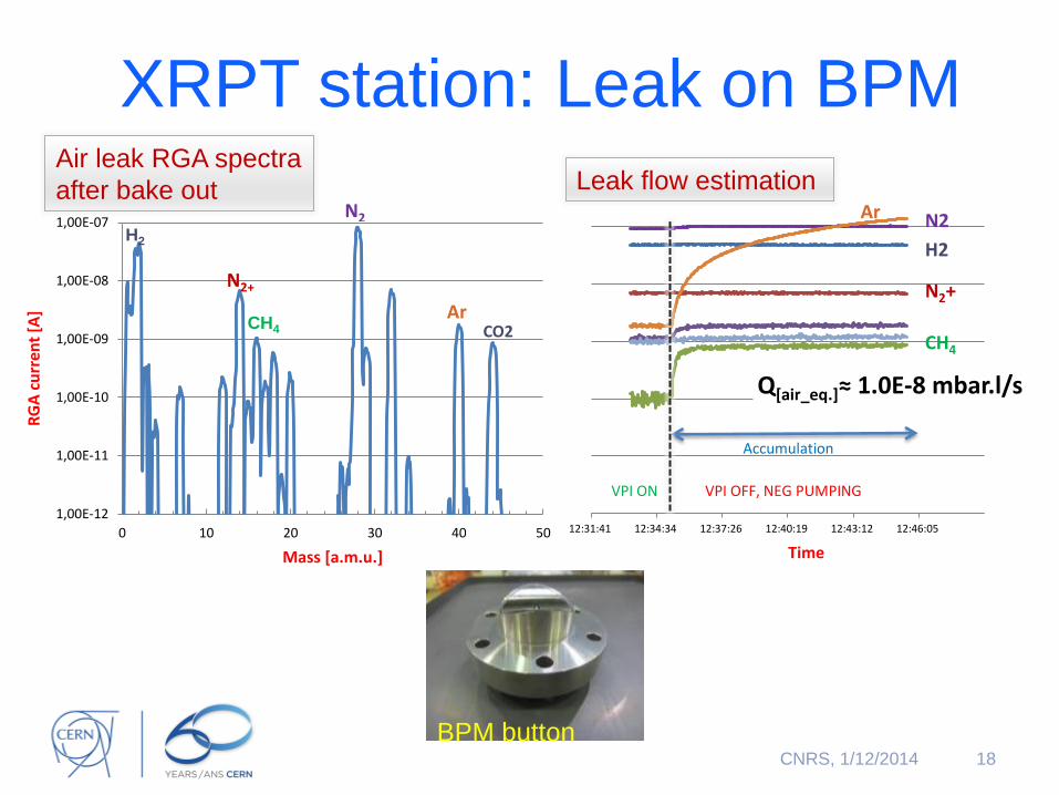
XRPT station: Leak on BPM
18
1,00E-12
1,00E-11
1,00E-10
1,00E-09
1,00E-08
1,00E-07
0 10 20 30 40 50
RG
A c
urr
ent
[A]
Mass [a.m.u.]
N2
N2+
Ar CO2
Air leak RGA spectra
after bake out
CH4
H2
12:31:41 12:34:34 12:37:26 12:40:19 12:43:12 12:46:05
Q[air_eq.]≈ 1.0E-8 mbar.l/s
Ar N2
VPI ON
Accumulation
VPI OFF, NEG PUMPING
H2
N2+
CH4
Leak flow estimation
Time
BPM button CNRS, 1/12/2014
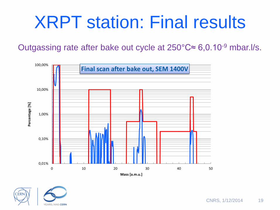
XRPT station: Final results
Outgassing rate after bake out cycle at 250°C≈ 6,0.10-9 mbar.l/s.
19
0,01%
0,10%
1,00%
10,00%
100,00%
0 10 20 30 40 50
Pe
rce
nta
ge [
%]
Mass [a.m.u.]
Final scan after bake out, SEM 1400V
CNRS, 1/12/2014
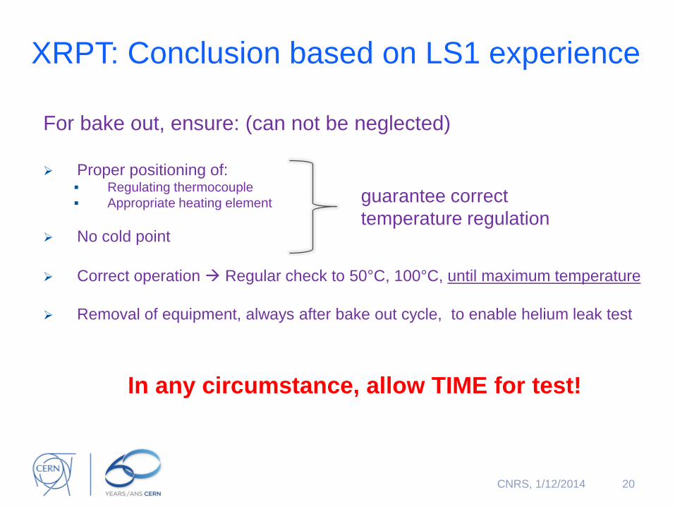
XRPT: Conclusion based on LS1 experience
For bake out, ensure: (can not be neglected)
Proper positioning of:
Regulating thermocouple
Appropriate heating element
No cold point
Correct operation Regular check to 50°C, 100°C, until maximum temperature
Removal of equipment, always after bake out cycle, to enable helium leak test
In any circumstance, allow TIME for test!
20
guarantee correct
temperature regulation
CNRS, 1/12/2014
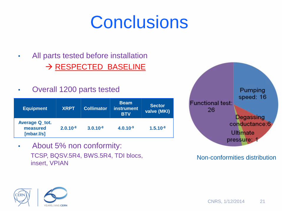
Conclusions
• All parts tested before installation
RESPECTED BASELINE
• Overall 1200 parts tested
• About 5% non conformity:
TCSP, BQSV.5R4, BWS.5R4, TDI blocs,
insert, VPIAN
21
Non-conformities distribution
Equipment XRPT Collimator
Beam
instrument
BTV
Sector
valve (MKI)
Average Q_tot.
measured
[mbar.l/s]
2.0.10-8 3.0.10-8 4.0.10-9 1.5.10-8
CNRS, 1/12/2014
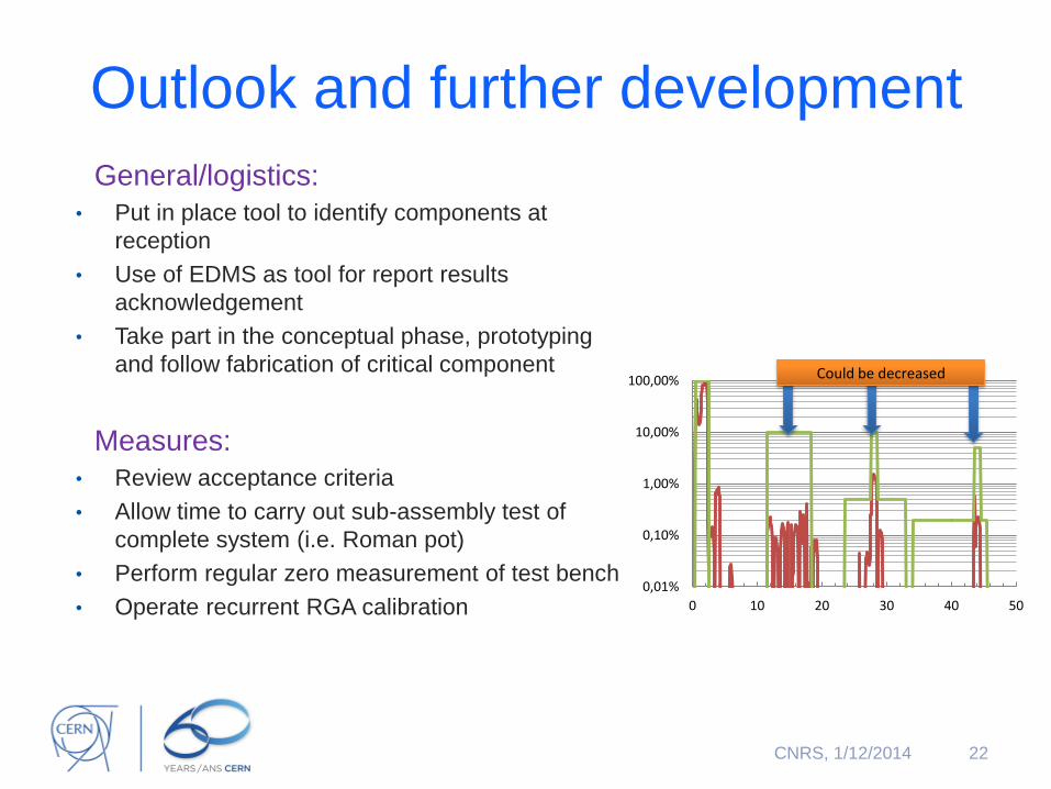
Outlook and further development
General/logistics:
• Put in place tool to identify components at
reception
• Use of EDMS as tool for report results
acknowledgement
• Take part in the conceptual phase, prototyping
and follow fabrication of critical component
Measures:
• Review acceptance criteria
• Allow time to carry out sub-assembly test of
complete system (i.e. Roman pot)
• Perform regular zero measurement of test bench
• Operate recurrent RGA calibration
22
0,01%
0,10%
1,00%
10,00%
100,00%
0 10 20 30 40 50
Could be decreased
CNRS, 1/12/2014
More details on this subject
23 CNRS, 1/12/2014

Thank you for your attention
24 CNRS, 1/12/2014