Université du Québec en Outaouais - di.uqo.cadi.uqo.ca/721/1/Abu Safia_Ousama_2014_thèse.pdf ·...
161
Université du Québec en Outaouais Département d'informatique et d'ingénierie Développement de Nouveaux Types de Ligne de Transmission à Base d’Inclusions/Cellules Métamatériaux et leurs Applications Potentielles Par Ousama Abu Safia Thèse présentée au Département d’informatique et d’ingénierie Pour l’obtention du grade de PHILOSOPHIAE DOCTOR (Ph.D) En sciences et technologies de l’information Jury d’évaluation Président du jury: Prof. Luigi Logrippo, Ph.D Directeur de recherche: Prof. Larbi Talbi, Ph.D Co-directeur de recherche: Dr. Khelifa Hettak, PhD Examinateur interne: Prof. Michael Korwin-Pawlowski, PhD Examinateur externe:: Dr. Nouredine Outaleb, PhD Examinateur externe: Prof. Abdel Razik Sebak, PhD Gatineau, Québec, Canada, 2014 © Droits réservés de Ousama Abu Safia, 2014.
Transcript of Université du Québec en Outaouais - di.uqo.cadi.uqo.ca/721/1/Abu Safia_Ousama_2014_thèse.pdf ·...
Université du Québec en Outaouais
Département d'informatique et d'ingénierie
Développement de Nouveaux Types de Ligne de
Transmission à Base d’Inclusions/Cellules
Métamatériaux et leurs Applications Potentielles
Par
Ousama Abu Safia
Thèse présentée au Département d’informatique et d’ingénierie
Pour l’obtention du grade de
PHILOSOPHIAE DOCTOR (Ph.D)
En sciences et technologies de l’information
Jury d’évaluation
Président du jury: Prof. Luigi Logrippo, Ph.D
Directeur de recherche: Prof. Larbi Talbi, Ph.D
Co-directeur de recherche: Dr. Khelifa Hettak, PhD
Examinateur interne: Prof. Michael Korwin-Pawlowski, PhD
Examinateur externe:: Dr. Nouredine Outaleb, PhD
Examinateur externe: Prof. Abdel Razik Sebak, PhD
Gatineau, Québec, Canada, 2014
© Droits réservés de Ousama Abu Safia, 2014.

- ii -

- iii -
Résumé
Développement de Nouveaux Types de Ligne de
Transmission à Base d’Inclusions/Cellules Métamatériaux et
leurs Applications Potentielles
Par
Ousama Abu Safia
Les métamatériaux sont des matériaux artificiels qui ont des propriétés physiques et
électriques inexistantes dans les matériaux conventionnels. Il existe deux approches
principales de conception des composants micro-ondes à base de métamatériaux:
l'approche de type résonance et l’autre approche de type ligne de transmission
artificielle. Dans cette thèse, de nouvelles cellules et inclusions métamatériaux basées
sur les deux approches de conception mentionnés sont proposées. Ces inclusions et
cellules ont de nombreux avantages par rapport aux implémentations conventionnelles
et remédient à de nombreuses limitations inhérentes à des inclusions et cellules bien
connues de la littérature.
L'avantage d'utiliser des lignes de transmission de type coplanaires (CPW) et leurs
discontinuités associées génèrent de nouvelles inclusions métamatériaux résonantes.
Ces nouvelles inclusions sont simulées, fabriquées, testées et appliqués dans plusieurs
circuits micro-ondes afin de valider leurs potentialités. De plus, ce travail propose une
nouvelle inclusion métamatériau bi-bande basé sur une technique hybride qui consiste
à combiner les deux techniques précitées.
Enfin, de nouvelles lignes de transmissions artificielles basées sur les éléments
distribués ayant des réponses non dispersives et/ou contrôlables en fonction de la

- iv -
fréquence sont introduites. Ces nouveaux éléments sont implémentés dans trois
circuits micro-ondes, à savoir, anneau résonateur bi-bandes, filtre passe bande large
bande, et coupleur hybride bi-bandes. Les trois applications montrent en evidence le
potentiel de ces nouveaux éléments.
- v -
University of Quebec in Outaouais
Department of Computer Science and Engineering
Development of New Types of Transmission Line-
Based Metamaterial Inclusions/Cells and Their
Applications
by
Ousama Abu Safia
A thesis presented to the University of Quebec in Outaouais in fulfillment
of the thesis requirement for the degree of Doctor of Philosophy in
Science and Information Technologies
(Emphasis: Microwave Engineering)
Committee members
Chairman: Prof. Luigi Logrippo, Ph.D
Research advisor: Prof. Larbi Talbi, Ph.D
Research co-advisor: Dr. Khelifa Hettak, PhD
Internal examiner: Prof. Michael Korwin-Pawlowski, PhD
External examiner: Dr. Nouredine Outaleb, PhD
External examiner: Prof. Abdel Razik Sebak, PhD
Gatineau, Quebec, Canada, 2014
© Ousama Abu Safia, 2014.

- vi -
- vii -
Abstract
Development of New Types of Transmission Line-Based
Metamaterial Inclusions/Cells and Their Applications
By
Ousama Abu Safia
Metamaterials are artificial materials which have physical and electrical
properties not existing in natural materials. There are two main design approaches
for metamaterial-based microwave devices: the resonance-type approach and the
artificial transmission line approach. In this thesis, new metamaterial cells and
inclusions based on the two aforementioned design approaches are proposed.
These inclusions and cells have many advantages over conventional
implementations and overcome many limitations related to well-known inclusions
and cells found in the literature. The advantage of using coplanar waveguide
(CPW) transmission lines and their discontinuities are utilized. These new
inclusions are modeled, simulated, fabricated, tested, and applied into several
microwave circuits and antennas to validate their potentiality. Also, this work
proposes a novel dual-resonant metamaterial inclusion based on a new hybrid
technique that combines the two aforementioned approaches for the first time. A
detailed design procedure, and a semi-distributed model for the inclusion were
proposed. Several applications to filters and antennas design were presented in
order to validate the new inclusion and the hybrid technique.

- viii -
- ix -
Acknowledgments
I would like to acknowledge the support and cooperation I received throughout the
time I have spent on this thesis:
First of all, I would like to gratefully acknowledge my promoters and supervisors,
Prof. Larbi Talbi, and Dr. Khelifa Hettak for their excellent guidance and
encouragement. Prof. Talbi was very generous with me in the last three years.
Besides his academic supervision, he has been supporting me financially during
my PhD study. Also, he gave me the opportunity to attend several national and
international conferences. Moreover, Prof. Talbi supported my applications for
many national scholarships, and several internal scholarships from UQO. He was
very flexible and understandable to my personal life situations and circumstances. I
will always be inspired by his nobility.
On the other hand, Dr. Khelifa's comments, suggestions and corrections were very
valuable to my research progress. Also, he gave me an excellent course in RF
technologies and systems. This course helped me to set strong theoretical and
technical bases for this dissertation.
I would like also to thank my colleagues in the laboratory: Dr. Tahar Haddad, Dr.
Mohammad Ghaddar, Vincent Fono, Betty Savitri, Dr. Ismail ben Mabrouk, and
Jamal Abdali for the long hours of pleasant talks and discussions.
I would also like to thank Professor Michael Korwin-Pawlowski for correcting the
written English of my proposal precisely. In the same way, I would like to thank
Dr. Nouredine Outaleb, Prof. Luigi Logrippo, and Prof. Abdel Razik Sebak for

- x -
devoting part of their time to review this thesis, and to be part of the examining
committee.
Finally I would like to mention a few people who are important to me; my parents
who pushed me in their own way to reach this level. Also, I am so glad to mention
the endless love that I have received from my best younger brother and friend,
Mamoon, and my two lovely sisters, Dr. Manar and Dr. Asma.

- xi -
Dedication
to my country, the Levant (Bilad al-Sham, Arabic: بالد الشام )
the land of the most ancient and brilliant civilizations on earth,
and those who have been giving their lives to flourish the Arab
Spring.

- xii -

- xiii -
"Investigate what is, and not what pleases"
Johann Wolfgang von Goethe

- xiv -
- xv -
Contents
Abstract vii
Acknowledgment ix
List of Publications xix
List of Abbreviations xxi
List of Symbols xxiii
List of Figures xxv
List of Tables xxix
CHAPTER 1..................................................................................................................1
Peface....................................................................................... .............................. 1
1.1.Thesis ................................................................................................................... 1
1.2.Organization ......................................................................................................... 3
CHAPTER 2 ............................................................................................................. 5
Introduction ............................................................................................................. 5
2.1 Introduction .......................................................................................................... 5
2.2 Research question ................................................................................................. 7
2.3 Objectives of the proposed research ...................................................................... 8
2.4 Methodology ........................................................................................................ 9
2.5 State of the art .....................................................................................................10
References .................................................................................................................15
CHAPTER 3 ............................................................................................................27
Investigation of CPW CRLH TLs..............................................................................27
3.1 Introduction .........................................................................................................27
3.2 Artificial (metamaterial-based) lines ....................................................................28
3.3 Advantages of coplanar waveguide-based elements .............................................29
- xvi -
3.4 Theory of composite right/lift handed transmission lines .....................................30
3.5 Practical considerations .......................................................................................33
3.6 Implementing the series connected capacitance....................................................33
3.7 Implementing the shunt inductor ..........................................................................37
3.8 Distributed left-handed metamaterial unit ............................................................38
3.9 Design of narrow band bandpass filter based on CRLH metamaterial unit ...........40
3.10 Dual-band property in CRLH TLs .....................................................................44
3.11 Quarter wavelength TLs and stubs .....................................................................47
3.12 A design example of a hybrid branch line coupler using CRLH TLs .................48
3.13 Distributed implementation of the dual-band HBLC using CPW TL ..................53
3.14 Design example of single-band distributed HBLC using CRLH TLs ..................54
3.15 Design example of dual-band HBLC (distributed)...............................................57
3.16 Conclusion ........................................................................................................59
References .................................................................................................................59
CHAPTER 4 ............................................................................................................63
A new type of transmission line-based metamaterial inclusions ...........................63
4.1 Theory and design of the new TL-based inclusion ..............................................63
4.2 Advantages of the proposed design over conventional SRRs................................67
4.3 A design example (simulation and measurements) ...............................................68
4.4 A modified AMM structure .................................................................................70
4.5 Other metamaterial inclusions based on CPW discontinuities ..............................71
4.6 Conclusion ..........................................................................................................75
References .................................................................................................................76
CHAPTER 5 ............................................................................................................77
Applications of the proposed TL-based inclusions .................................................77
5.1 Dual-band bandstop filter example ......................................................................77
5.2 Theory of slow wave propagation in AMM-loaded TLs .......................................81
- xvii -
5.3 Miniature hybrid branch line coupler (HBLC) .....................................................88
5.4 Conclusions .........................................................................................................94
References .................................................................................................................94
CHAPTER 6 ............................................................................................................97
Dual-resonant metamaterial inclusion using composite right/left-handed
transmission line elements.......................................................................................97
6.1 Higher harmonic resonance in the TL-based inclusion ........................................98
6.2 Theory of dual-resonant inclusion ........................................................................98
6.3 Design procedure for the dual-resonant inclusion ............................................... 100
6.4 Design example, simulated and measured results ............................................... 102
6.5 Applications to antenna designs ......................................................................... 104
6.6 Conclusion ........................................................................................................ 110
References .................................................................................................................59
CHAPTER 7 .......................................................................................................... 113
Afterword .............................................................................................................. 113
7.1 Summary ........................................................................................................... 113
7.2 Contributions ..................................................................................................... 114
7.3 Recommended future work ................................................................................ 115
Appendix: Summary of the thesis in French ....................................................... 115

- xviii -

- xix -
List of Publications
A. Published refereed journal
1. Abu Safia, O.; Talbi, L.; Hettak, K., "A New Type of Transmission Line-Based
Metamaterial Resonator and Its Implementation in Original Applications," IEEE
Transactions on Magnetics , vol.49, no.3, pp.968,973, March 2013.
B. International conference papers
2. Abu Safia, O.; Talbi, L.; Hettak, K., "Dual-Band Split-Ring Resonator Using
Composite Right-/Left-Handed Coplanar Waveguide Transmission Line-Based
Elements," 2014 27th IEEE Canadian Conference on Electrical & Computer
Engineering (4-7 May 2014).
3. Abu Safia, O..; Talbi, L.; Hettak, K., "A novel artificial magnetic material based on
a CPW series-connected resonator and its implementation in original
applications," Antennas and Propagation (EuCAP), 2013 7th European Conference
on , vol., no., pp.2756,2760, 8-12 April 2013
4. Abu Safia, O.; Talbi, L.; Hettak, K.; Kabiri, A., "CPW discontinuities-based
metamaterial inclusions," Antennas and Propagation Society International
Symposium (APSURSI), 2013 IEEE , vol., no., pp.1176,1177, 7-13 July 2013
5. Abu Safia, O.; Talbi, L.; Hettak, K., "A new class of artificial magnetic materials
based on a modified uniplanar series resonator and their implementation in original
applications," IEEE International Conference on Microwave Magnetics,
Kaiserslautern Germany 26-29 August 2012.
6. Abu Safia, O.; Talbi, L.; Hettak, K.; Kabiri, A., "Dual-band SRR using CRLH TL
based elements," IEEE Antennas and Propagation Society International Symposium
(APSURSI), Memphis, USA July, 2014.

- xx -
C. In progress works
7. Abu Safia, O.; Talbi, L.; Hettak, K., "CPW-fed single folded slot antenna based on
a Dual-Resonat Metamaterial Inclusion having composite right/ left-handed
Transmission Lines elements ", Microwaves, Antennas & Propagation, IET
8. Abu Safia, O.., Talbi, L.; Hettak, K.,"Dual-band HBLC using dual-band CPW
CRLH cells," Electronics Letters.
D. Other journal publications
9. O. Abu Safia, A. A. Omar, and M. C. Scardelletti, "Design of dual-band bandstop
coplanar waveguide filter using uniplanar series-connected resonators," Progress In
Electromagnetics Research Letters, Vol. 27, 93-99, 2011.
10. Omar, A. A., Abu Safia, O. H., and Scardelletti, M. C. (2011). "Design of
dual-band bandpass coplanar waveguide filter," International Journal of
Electronics, 98, 311–322. 2011.
- xxi -
List of Abbreviations
CPW coplanar waveguide
HBLC hybrid branch line coupler
LH left handed
MTM metamaterial
CRLH composite right/left handed
TL transmission line
AMM artificial magnetic material
SRR split ring resonator
RF radio frequency
GSM global system for mobile communications
WCDMA wideband code division multiple access
RH right handed
SMT surface mount technology
S-SRR square split ring resonator
EMT effective medium theory
IDC interdigital capacitors
SSI short-circuited stub inductors
MS microstrip
TW thin wire
BWs backward waves
p.u.l per unit length
SDIE space-domain integrated equations
DB dual band
BPF band pass filter
BSF band stop filter
LE lumped element
SIW substrate integrated waveguide

- xxii -

- xxiii -
List of Symbols
speed of electromagnetic waves in vacuum
wavelength of electromagnetic waves in vacuum
angular frequency of an electromagnetic wave
effective permittivity
effective permeability
k wave vector
E electric field intensity
H magnetic field intensity
relative permittivity of a material
relative permeability of a material
magnetic susceptibility
M mutual inductance
conductivity
capacitance per unit length of an inclusion
inductance per unit area of an inclusion
propagation constant
characteristic impedance
permittivity of the free space
permeability of the free space
dissipation factor
phase shift
Resonant angular frequency
normalized frequency with respect to the resonant frequency
frequency bandwidth
Re real part of a complex function
Im imaginary part of a complex function
radiation efficiency

- xxiv -
- xxv -
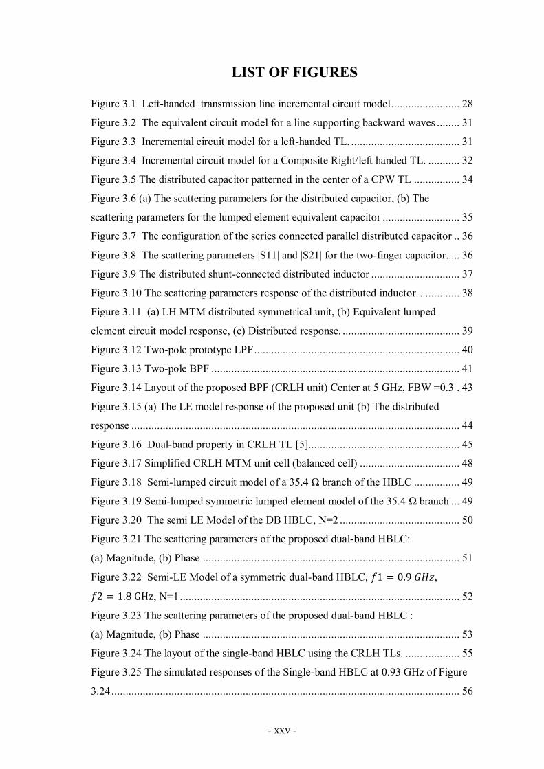
LIST OF FIGURES
Figure 3.1 Left-handed transmission line incremental circuit model ........................ 28
Figure 3.2 The equivalent circuit model for a line supporting backward waves ........ 31
Figure 3.3 Incremental circuit model for a left-handed TL. ...................................... 31
Figure 3.4 Incremental circuit model for a Composite Right/left handed TL. ........... 32
Figure 3.5 The distributed capacitor patterned in the center of a CPW TL ................ 34
Figure 3.6 (a) The scattering parameters for the distributed capacitor, (b) The
scattering parameters for the lumped element equivalent capacitor ........................... 35
Figure 3.7 The configuration of the series connected parallel distributed capacitor .. 36
Figure 3.8 The scattering parameters |S11| and |S21| for the two-finger capacitor..... 36
Figure 3.9 The distributed shunt-connected distributed inductor ............................... 37
Figure 3.10 The scattering parameters response of the distributed inductor. .............. 38
Figure 3.11 (a) LH MTM distributed symmetrical unit, (b) Equivalent lumped
element circuit model response, (c) Distributed response. ......................................... 39
Figure 3.12 Two-pole prototype LPF ........................................................................ 40
Figure 3.13 Two-pole BPF ....................................................................................... 41
Figure 3.14 Layout of the proposed BPF (CRLH unit) Center at 5 GHz, FBW =0.3 . 43
Figure 3.15 (a) The LE model response of the proposed unit (b) The distributed
response ................................................................................................................... 44
Figure 3.16 Dual-band property in CRLH TL [5]..................................................... 45
Figure 3.17 Simplified CRLH MTM unit cell (balanced cell) ................................... 48
Figure 3.18 Semi-lumped circuit model of a 35.4 Ω branch of the HBLC ................ 49
Figure 3.19 Semi-lumped symmetric lumped element model of the 35.4 Ω branch ... 49
Figure 3.20 The semi LE Model of the DB HBLC, N=2 .......................................... 50
Figure 3.21 The scattering parameters of the proposed dual-band HBLC:
(a) Magnitude, (b) Phase .......................................................................................... 51
Figure 3.22 Semi-LE Model of a symmetric dual-band HBLC, ,
, N=1 .................................................................................................. 52
Figure 3.23 The scattering parameters of the proposed dual-band HBLC :
(a) Magnitude, (b) Phase .......................................................................................... 53
Figure 3.24 The layout of the single-band HBLC using the CRLH TLs. ................... 55
Figure 3.25 The simulated responses of the Single-band HBLC at 0.93 GHz of Figure
3.24 .......................................................................................................................... 56
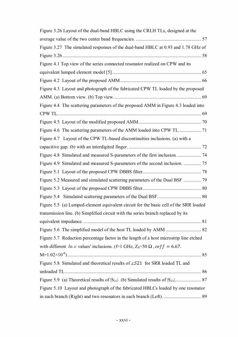
- xxvi -
Figure 3.26 Layout of the dual-band HBLC using the CRLH TLs, designed at the
average value of the two center band frequencies. .................................................... 57
Figure 3.27 The simulated responses of the dual-band HBLC at 0.93 and 1.78 GHz of
Figure 3.26 ............................................................................................................... 58
Figure 4.1 Top view of the series connected resonator realized on CPW and its
equivalent lumped element model [5]. ...................................................................... 65
Figure 4.2 Layout of the proposed AMM. ................................................................ 66
Figure 4.3 Layout and photograph of the fabricated CPW TL loaded by the proposed
AMM. (a) Bottom view. (b) Top view. ..................................................................... 69
Figure 4.4 The scattering parameters of the proposed AMM in Figure 4.3 loaded into
CPW TL. .................................................................................................................. 69
Figure 4.5 Layout of the modified proposed AMM .................................................. 70
Figure 4.6 The scattering parameters of the AMM loaded into CPW TL. ................. 71
Figure 4.7 Layout of the CPW TL-based discontinuities inclusions. (a) with a
capacitive gap. (b) with an interdigited finger. .......................................................... 72
Figure 4.8 Simulated and measured S-parameters of the first inclusion. ................... 74
Figure 4.9 Simulated and measured S-parameters of the second inclusion. .............. 75
Figure 5.1 Layout of the proposed CPW DBBS filter............................................... 78
Figure 5.2 Measured and simulated scattering parameters of the Dual BSF .............. 79
Figure 5.3 Layout of the proposed CPW DBBS filter............................................... 80
Figure 5.4 Simulated scattering parameters of the Dual BSF. .................................. 80
Figure 5.5 (a) Lumped-element equivalent circuit for the basic cell of the SRR loaded
transmission line. (b) Simplified circuit with the series branch replaced by its
equivalent impedance. .............................................................................................. 81
Figure 5.6 The simplified model of the host TL loaded by AMM ............................ 82
Figure 5.7 Reduction percentage factor in the length of a host microstrip line etched
with different values' inclusions. (f=1 GHz, Z0=50 Ω
M=1.02×10⁻⁸
) ........................................................................................................... 85
Figure 5.8 Simulated and theoretical results of for SRR loaded TL and
unloaded TL ............................................................................................................. 86
Figure 5.9 (a) Theoretical results of |S21| (b) Simulated results of |S21|..................... 87
Figure 5.10 Layout and photograph of the fabricated HBLCs loaded by one resonator
in each branch (Right) and two resonators in each branch (Left). .............................. 89
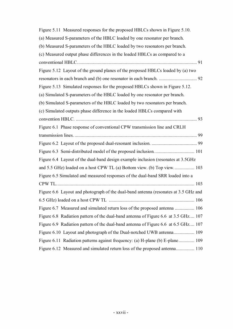
- xxvii -
Figure 5.11 Measured responses for the proposed HBLCs shown in Figure 5.10.
(a) Measured S-parameters of the HBLC loaded by one resonator per branch.
(b) Measured S-parameters of the HBLC loaded by two resonators per branch.
(c) Measured output phase differences in the loaded HBLCs as compared to a
conventional HBLC. ................................................................................................. 91
Figure 5.12 Layout of the ground planes of the proposed HBLCs loaded by (a) two
resonators in each branch and (b) one resonator in each branch. ............................... 92
Figure 5.13 Simulated responses for the proposed HBLCs shown in Figure 5.12.
(a) Simulated S-parameters of the HBLC loaded by one resonator per branch.
(b) Simulated S-parameters of the HBLC loaded by two resonators per branch.
(c) Simulated outputs phase difference in the loaded HBLCs compared with
convention HBLC. ................................................................................................... 93
Figure 6.1 Phase response of conventional CPW transmission line and CRLH
transmission lines. .................................................................................................... 99
Figure 6.2 Layout of the proposed dual-resonant inclusion. ..................................... 99
Figure 6.3 Semi-distributed model of the proposed inclusion. ................................ 101
Figure 6.4 Layout of the dual-band design example inclusion (resonates at 3.5GHz
and 5.5 GHz) loaded on a host CPW TL (a) Bottom view. (b) Top view. ................ 103
Figure 6.5 Simulated and measured responses of the dual-band SRR loaded into a
CPW TL. ................................................................................................................ 103
Figure 6.6 Layout and photograph of the dual-band antenna (resonates at 3.5 GHz and
6.5 GHz) loaded on a host CPW TL ...................................................................... 106
Figure 6.7 Measured and simulated return loss of the proposed antenna ................ 106
Figure 6.8 Radiation pattern of the dual-band antenna of Figure 6.6 at 3.5 GHz. ... 107
Figure 6.9 Radiation pattern of the dual-band antenna of Figure 6.6 at 6.5 GHz. ... 107
Figure 6.10 Layout and photograph of the Dual-notched UWB antenna ................. 109
Figure 6.11 Radiation patterns against frequency: (a) H-plane (b) E-plane ............. 109
Figure 6.12 Measured and simulated return loss of the proposed antenna ............... 110

- xxviii -
- xxix -
LIST OF TABLES
Table 3.1 The lumped elements values of the circuit configurations of the BPF shown
in Figure 3.13 ........................................................................................................... 42
Table 3.2 The characteristics of the CRLH based bandpass filter centered at 5 GHz . 44
Table 3.3 Performance parameters of the single-band HBLC designed at 0.9 GHz .. 56
Table 3.4 Characteristics of the dual-band HBLC at 0.93 GHz and 1.78 GHz ......... 59
Table 4.1 Performance of the proposed AMM (Designed fc = 3.4 GHz).................... 70
Table 4.2 Performance of the AMM shown in Figure 4.5 ........................................ 71
Table 4.3 Performance of the two inclusions of Figure 4.7....................................... 74
Table 5.1 Performance of the proposed DBBSF at the first and ................................ 78
Table 5.2 Performance of the proposed DBBSF at the second band .......................... 79
Table 5.3 Performance of the proposed DBBSF at the first band .............................. 80
Table 5.4 Performance of the proposed DBBSF at the second band ......................... 81
Table 5.5 Performance of the HBLCs (measured response) ..................................... 90
Table 5.6 Performances of the HBLCs (simulated response) ..................................... 93
Table 6.1 Characteristic parameters of the dual-band inclusion of Fig 6.5. ............. 104

- xxx -
- 1 -
CHAPTER 1
Preface
1.1. Thesis
Metamaterials are composite human-made materials that have properties not found in
natural materials. Metamaterials are realized by embedding electrically small metallic
inclusions aligned in parallel to a host dielectric medium. In the presence of a magnetic
field, an electric current is induced within the inclusions leading to the emergence of an
enhanced magnetic response inside the medium at their resonant frequencies.
Two main design approaches are used to produce metamaterial-based devices at
microwave frequencies. Firstly, the resonance-type (split ring resonators) approach, and
secondly, the composite right/left-handed (CRLH) transmission line (TL) approach.
The resonance-type approach is based on loading conventional host transmission
lines with artificial magnetic material (AMM) inclusions, such as split ring resonators.
Etching a transmission line with AMM inclusions enables the generation of current
loops inside the inclusions. This magnetic coupling phenomenon produces a stopband
response around the AMM's resonant frequency. The stopband response can be
physically interpreted as a result of the negative effective permeability of the host TL
around the inclusion's resonant frequency.
The second metamaterial design approach is the composite right/left-handed
transmission lines approach. These lines consist of two parts: a right-handed part;
usually realized using conventional transmission line segments, and a left-handed part
which consists of a chain of series-connected capacitors separated by shunted connected
inductors (the dual configuration for the lumped element model of a conventional TL).
- 2 -
CRLH TLs have a nonlinear phase-frequency curve response, and hence, the frequency
offset and phase slope can be controlled to obtain a similar response at two different
frequencies. On other words, these lines support dual-band operations which allow
producing arbitrary dual-band circuits.
This dissertation focuses particularly on: firstly, utilizing several coplanar waveguide
(CPW) transmission lines discontinuities and elements to produce a new type of TL-
based single-resonant metamaterial inclusions, and secondly, producing a dual-resonant
metamaterial inclusion derived from the single-resonant inclusions by using a new
hybrid approach that combines the two main metamaterial design approaches.
First, the composite right/left-handed transmission lines approach is investigated
theoretically, then, a CPW-based implementation for these artificial lines is proposed.
The well-known dual-band property for these lines is validated by designing a dual-
band hybrid branch line coupler.
Second, a new single-resonant transmission line-based metamaterial resonator that
has many advantages over conventional split ring resonators (SRRs) is proposed. The
structure is based on a modified coplanar waveguide series-connected resonator folded
to form a square loop layout. The resonant frequency for the inclusion is calculated and
compared with simulations and measurements results.
Third, in order to illustrate the potentiality of the proposed inclusion, two inclusion-
based microwave devices are designed: a dual-band bandstop filter, and a miniaturized
hybrid branch line coupler (HBLC). Miniaturizing the size of the HBLC is based on a
new proposed loading technique which allows decreasing the electric length of the host
transmission lines.
Fourth, a new hybrid technique which combines the two previous metamaterial
design approaches is proposed, resulting in a dual-resonant response. CPW CRLH TLs
- 3 -
are used to replace the conventional lines in the single-resonant prototype inclusion to
obtain a dual-resonant metamaterial inclusion. Hence, the new inclusion contains
composite right/left-handed transmission line-based passive elements.
Finally, to validate the new hybrid approach and the resultant dual-resonant
inclusion, two antenna designs which are based on that inclusion are proposed: a dual-
band CPW-fed single folded slot antenna, and a dual-band notched ultra wide-band
antenna.
1.2. Organization
The thesis contains seven chapters including preface and afterword. This thesis is
organized as follows:
Chapter 2 presents the introduction, research question, objectives, methodology and
the state of the art.
Chapter 3 presents the method used to synthesize composite right/left-handed
transmission lines. Then, these lines are used to produce a simple bandpass filter. In
addition, the dual-band property found in these lines is validated by proposing CPW
dual-band hybrid branch line couplers.
Chapter 4 introduces new TL-based single-resonant inclusions that utilize series-
connected CPW passive elements patterned in its the center conductor. Also, a
lumped element model that predicts the inclusions' resonant frequencies is
introduced.
Chapter 5 proposes two applications for the new inclusions: a dual-band bandstop
filter and a compact hybrid branch line coupler. Also, a thorough investigation of the
effect of loading our inclusions in increasing the electrical length of the host TLs is

- 4 -
introduced. This phenomenon explains the ability to produce compact microwave
circuits using our inclusions.
Chapter 6 introduces a new technique in which CRLH TLs replace the conventional
lines in the single-resonant prototype inclusion. This technique allows producing a
dual-resonant metamaterial inclusion. The designed inclusion is deployed into two
antenna designs to verify its dual-resonant response impact.
Chapter 7 draws the major conclusions and contributions, and addresses the
recommended future work.
- 5 -
CHAPTER 2
2 Introduction
2.1 Introduction
Metamaterials are artificial materials which have electromagnetic properties not
readily available in nature. These materials are synthesized to provide specific
permeability and permittivity values over microwave frequency ranges [1]. The material
medium of metamaterials contains electrically small inclusions arranged periodically in
the host medium [1]. These inclusions change the electromagnetic properties of the host
medium due to the inclusions' resonance behavior in the presence of an electromagnetic
excitation [1]. When the host medium is excited by electromagnetic waves having
wavelengths much larger than the maximum dimension of the metamaterial structure,
the medium exhibits new physical and electrical features not covered by natural
materials. At this point, the non-homogeneous artificial structures of metamaterials can
be characterized as homogenous mediums described by effective permittivity and
effective permeability parameters. This condition ensures that the electromagnetic wave
is refracted and not diffracted in the material medium of metamaterials [2].
Artificial magnetic materials (AMMs) are small metallic looped-shape inclusions,
aligned in parallel planes perpendicular to the direction of incident magnetic field. The
incident electromagnetic field induces an electric current on the inclusions leading the
emergence of a magnetic response inside the medium at the inclusions' resonant
frequencies. The resonant frequency of any AMM is determined by the size and
geometry of its layout.
- 6 -
One main target for microwave circuits designers is to decrease the size of AMM-
based devices. This can be simply achieved by decreasing the size of these conventional
inclusions [3]. However, due to the limited lateral resolution of standard fabrication
systems, it is difficult to drive conventional AMM dimensions below one-tenth of a
wavelength at resonance, and hence, new AMM inclusions having more compact
topologies need to be considered [4]-[6].
To estimate and characterize the performance of AMM, several related lumped
element (LE) models have been introduced. For instant, a lumped element model of a
host conventional transmission line loaded by SRRs has been proposed in [3]. The
model contains a series-connected shunt LC resonator attached to the LE model of the
host TL. However, accurate LE models that reflect the magnetic coupling between the
host TL and the AMMs need more investigations.
Recent wireless communication systems demand radio frequency (RF) devices
operating at multiple frequency bands. For example, in the second and third generation
cellular mobile systems (GSM and WCDMA, respectively) the RF transceivers must be
able to transmit and receive signals at 900 and 1800 MHz, respectively. Therefore,
microwave devices such as filters, power dividers and branch line couplers used in these
systems should operate at multiple frequency bands. The second design approach of
metamaterials, namely the composite right/left-handed transmission lines approach,
provides the dual-band response needed to produce such dual-band devices [7], [8]. By
controlling the slope of the phase-frequency dispersive curve of a CRLH TL, several
dual-band devices can be designed [8]-[11].
In CRLH TLs, there are right-handed (RH) and left-handed (LH) transmission line
parts attached together in order to get several new appealing properties [7],[8]. A
balanced combination of the left-handed and right-handed parts permits backward

- 7 -
waves propagation (passband response) for a wide range of frequencies [7]. The right-
handed section is usually realized using microstrip or coplanar waveguide (CPW)
transmission lines. These host lines introduce parasitic elements that cannot be
neglected, and they should be taken into account to describe the propagation
characteristics of these lines accurately. On the other hand, the LH part is realized using
a chain of series-connected capacitors and shunt-connected inductors. These capacitors
and inductors are implemented using either distributed elements or surface mount
technology (SMT) components [7], [8].
SMT components have many advantages such as their small size, and their relatively
frequency independent lumped element values within a specific range of frequency.
Moreover, these components can be deployed and integrated easily into microwave
circuits. However, SMT elements operate in a limited frequency range due to the
parasitic effects that cause self-resonance [12]. In addition, their nominal values are
restricted to those provided by manufacturers, and finally, SMT elements are relatively
expensive; soldering is necessary and it goes against the full integration of microwave
components [12].
On the other hand, using distributed elements overcomes the aforementioned
disadvantages. However, one main limitation of using distributed elements is their
frequency-selective response; therefore, new techniques to overcome this problem have
to be investigated.
2.2 Research question
In spite of the large number of AMM inclusions introduced in the literature, most of
these inclusions have similar geometrical structures and electrical behavior to
conventional split ring resonators. Moreover, these inclusions have many common
- 8 -
limitations. For example, they have complex expressions for their LC elements. This
leads to complex expressions for their resonant frequencies. Therefore, it is important to
produce new AMMs that overcome such limitations, and to have new properties such as
the dual-resonant response, in addition to have accurate and simple LE model to
estimate their resonant frequencies.
Utilizing distributed passive elements to design CRLH TLs has several advantages
over lumped elements. However, their frequency-selective behavior represents a major
disadvantage especially when they are implemented in dual-band frequency circuits.
Hence, new techniques to overcome this problem should be considered.
CPW TL discontinuities have not been utilized to produce AMM inclusions. These
structures are expected to share the same appealing properties with conventional CPW
TLs
A well-designed dual-resonant inclusion having a controllable resonant frequency
can replace the need for two AMM inclusions having different sizes. Also, this
inclusion can be applied into dual-band microwave (MW) applications and antennas.
2.3 Objectives of the proposed research
Series-connected resonators based on special stubs patterned in the center strip of a
CPW TL have been introduced in [13]. These resonators can be modified and reshaped
in order to produce new AMM inclusions. The new inclusions, which consist of open-
ended and short ended stubs, are designed to operate at the ultra-high frequency range.
Because the passive elements within the new inclusion are based on TLs, the new
inclusion overcomes many limitations and disadvantages found in the conventional
inclusions. For example, it has the ability to control the quality and reduction
(compactness) factors in MW devices. Unlike conventional inclusions, the proposed

- 9 -
inclusions have independently controllable distributed elements (the inductive and
capacitive elements are approximately frequency independent). This can simplify
controlling and estimating the resonant frequency and the quality factor. In addition,
special CRLH TLs can replace the conventional TLs in the proposed single-resonant
inclusion in order to have dual-band AMMs, and hence, new compact dual-band MW
circuits can be produced.
The aforementioned technique in which CRLH lines replace conventional TL can be
used to design new CRLH TL-based passive distributed elements having constant
equivalent lumped element values at two different center band frequencies. Therefore,
the responses of dual-band components based on these artificial lines can be enhanced.
The proposed techniques and structures are validated by designing and fabricating
several dual-band filters, and branch line couplers and antennas.
2.4 Methodology
High quality distributed capacitors and inductors based on open-ended and short-
ended stubs, respectively, patterned in the center conductor of CPW TLs, are designed
and simulated using a full-wave electromagnetic simulation tool [14]. Several proposed
miniaturization techniques are utilized [15]-[17]. The simulated results are compared to
the theoretical results of the equivalent lumped-element model. The LE model is
adjusted to consider the CPW discontinuities effect [18]-[20]. After that, special CRLH
TLs are designed to replace the distributed passive elements, in order to get the dual-
band response. From the simulated scattering parameters values the capacitance and
inductance within the CRLH TLs are extracted and compared with the designed values.
Optimizing the physical dimensions of these artificial TLs is considered to enhance
their response, and later, these meta-lines are deployed into the new proposed AMM
- 10 -
inclusions. A theoretical model based on simple TL theory to calculate the resonant
frequency of the proposed AMMs is introduced. After validating the responses of the
proposed AMMs and CRLH cells by fabrication and measurements, several dual-band,
high performance and ultra-compact MW circuits are produced. Finally, the novelty of
the proposed techniques and designs is evaluated and compared with the existing MW
circuits of the literature [21]-[26].
2.5 State of the art
Split ring resonators (SRRs) were first introduced by Pendry et al. [1]. Since then,
numerous SRRs having various geometrical configurations have been proposed [27]-
[31]. However, most of these SRRs are derived from the prototype structure proposed in
[1]. For example, in [27] a square split ring resonator (S-SRR) was proposed which has
more degrees of freedom from a design point of view, and more magnetic coupling with
the host transmission line, than SRRs. Saha et al. built a theoretical model for S-SRRs
to estimate their resonant frequency and their magnetic polarization in [28]. They also
investigated the bandstop behavior of these resonators when loaded into CPW. In [29],
bandstop filters based on SRRs placed on the back side of CPW substrate were first
introduced. These filters give significant insertion loss in the rejection band with very
good frequency selectivity near the resonant frequency. Baena et al. proposed many
SRR topologies with different broken-loop shapes, and their equivalent lumped element
models [3]. Although the number of capacitors and inductors varies in each topology, it
can always be simplified to a series-connected LC resonator mutually coupled with the
host TL. In [30], a spiral resonator of one metallic planar piece is proposed in order to
facilitate the fabrication process because of the absence of the narrow slots between the
- 11 -
strips. In [31], a modified broadside coupled SRR was proposed by Marques et al. as an
alternative to a conventional SRR in order to avoid the bi-anisotropic effects.
The resonance behavior in artificial magnetic materials (AMMs) results from the
perpendicular excitation of the time varying magnetic field through their sectional areas;
therefore, induced resonating currents flow inside the broken-loops which act as
magnetic dipole moments. This physical phenomenon can be modeled as a series-
connected LC resonator, mutually coupled with the host TL [29]. The real part of the
effective permeability (μr) within the host dielectric substrate medium encounters a
bipolar impulse response in the vicinity of the resonant frequency (fc), i.e., μr increases
positively just before fc then it falls down to negative values with high slope rate after
that [32]. Mapping this phenomenon to filter applications, it can be concluded that a
bandstop response can be detected in the resonant frequency range.
The resonance and dispersive behavior in SSRs are entirely determined by the
geometry and the size of the metallic broken-loop inclusions [1]. For all the proposed
geometries which are driven from conventional SRRs there are some advantages and
disadvantages.
AMMs are suitable for compact microwave devices such as filters and diplexers due
to their resonance nature, and due to the controllability of the electrical properties in
AMM-based TLs which include the dispersion diagram and the characteristic
impedance of such artificial lines. It is possible to design components with smaller size
and superior performance compared to conventional implementation (such as enhanced
bandwidth devices), and devices based on new functionalities such as dual-band
circuits.
Several numerical and analytical methods were introduced to characterize the
constitutive parameters for AMMs [33]-[37]. In [33], Smith and Pendry proposed a field

- 12 -
averaging method in order to homogenized a periodic structure that contains several
metamaterial cells with different geometries. The electric and magnetic fields were
averaged and calculated at the edges of two successive cubic lattices. In [34], the
effective parameters of a transmission line loaded with asymmetrical SRRs were
calculated by proposing an equivalent bianisotropic medium, which imitates the effect
of asymmetric unit cells. In [35], analytical expressions for the relative permittivity and
permeability of SRRs were introduced based of a simple transmission line theory. The
two parameters were extracted from the derived expressions of reflection and
transmission coefficients. In [36], effective material parameters in metamaterial were
calculated using a modal approach combined with the Finite Integration Technique (a
generalized FDTD method). The parameter fitting of dispersive models (PFDMs)
method was used in [37] to extract the effective material parameters from the scattering
parameters of a double negative metamaterial structure.
Many lumped element models are proposed to model SRRs and their interaction with
transmission lines. [3],[38]-[41]. For example, In [38], successive transmission line
sections connected in series with two capacitive π networks that represent the split gaps
were used to represent a microstrip double SRR geometry. In [39], an equivalent circuit
model for a singly split ring resonator (SSRR) based on bulk and distributed elements
was proposed. A set of differential equations with boundary conditions imposed at the
position of the split was solved to find the voltage and current variations in the inner
and outer rings. In [40], a new equivalent circuit model for two-dimensional cross
embedded SRR was proposed. Each column of the SRRs array was modeled as a quasi-
solenoid under magnetic induction. Moreover, electromagnetic coupling between each
column was considered. The quasi-analytical model used to compute the polarizabilites
of the edge- and broadside-coupled SRRs in [41] was also used to find the lumped LC

- 13 -
values for several other SRR configurations and their complementary topologies [3].
From these models, the stopband and passband characteristics can be easily explained.
The second approach to produce metamaterial-based components and circuits is a
non-resonant artificial transmission lines-based approach called composite right/left
handed transmission lines [42]. Their nonlinear phase slope response makes them
convenient to produce arbitrary dual-band circuits by simply replace the conventional
lines in prototype circuits [43], [8]. A two-dimensional (2-D) CRLH TLs have been
investigated in [44]. Their dispersive diagram has been derived analytically in [45].
Similar planar cells were utilized to produce infinite wavelength resonant antennas with
monopolar radiation patterns in [46]. Other 2-D planar resonant-type distributed
structure based on complimentary split ring resonators and series gap capacitors has
been proposed in [47]. In [48], a leaky-wave antenna with tunable radiation angle and
beamwidth based on CRLH microstrip structure was proposed. The antenna has
varactor diodes to tune its resonant frequency. In [49], a compact four unit cell antenna
based on a CRLH cell was produced. The antenna utilizes the anti-parallel phase and
group velocities of CRLH cells at their functional mode where the propagation constant
increases as the frequency decreases, and hence, a small size antenna can be realized.
Another leaky-wave antenna based on CRLH microstrip TL is proposed in [05]. The
structure eliminates the open-stopband effects and has a constant radiation efficiency,
obtained based on an accurate parametric design procedure and a full-wave numerical
modal approach. In [51], an amplifier was added to the CRLH TL-based antenna design
to regenerate the amplitude of a signal progressively leaked out in the radiation process.
Therefore, high-gain active leaky-wave antenna was produced.

- 14 -
CRLH cells were realized in different types of transmission lines and technologies.
For example, a coplanar waveguide CRLH TL was realized in [52]. Recently, substrate
integrated waveguide (SIW) CRLH cells were proposed [53].
Other non-radiating devices which utilize the appealing properties of CRLH TLs are
enormously found in the literature. This includes duplexers [54], directional couplers
[55], power splitters [56], phase shifters [57], coupled-line couplers [58], power
amplifiers [09], [60], and compressive receivers [61].
Hybrid approaches that combine the two metamaterial design approaches have been
reported in [62]-[67]. In [62], CPW lines are loaded by complementary SRRs combined
with series capacitive gaps in the conductor strip, located above the complementary
SRRs, and grounded inductive stubs. This structure was used to obtain a compact UWB
filter [62]. Gil et al proposed a comparable structure realized on a microstrip
transmission line. The structure-based artificial lines were used to produce a compact
power divider and a high selective bandpass filter [63]. In [64], a balanced CRLH line
was realized by loading the host CPW TL with square-SRRs, located below the
positions occupied by the short-circuited shunt-connected inductive stubs. A proper
tuning of the resonators’ dimensions and the stubs lengths allows wider transmission
characteristics. In [65], capacitive open-ended stubs are connected to the SRR rings to
modify the right-handed band’s feature in a SRR-loaded CPW TL. The structure has a
wide passband with high attenuation rates besides the passband due to its pair of
transmission zeros at each side of the passband. These features make the structure very
attractive for filter application. In [66], extra series and shunt capacitances were added
to the prototype negative refractive index uniplanar transmission line proposed in [67].
The structure is balanced with wideband response due to the fine tuning between its
advance and delay phase offset sections.

- 15 -
Other related structure, called dual CRLH, was proposed by Caloz [68]. The
structure exhibits its RH band at low frequencies and its LH band at high frequencies.
Several SRR-based balanced dual CRLH TLs with wideband bandpass response have
been reported [69], [70].
References
[1] Pendry, J.B.; Holden, A.J.; Robbins, D.J.; Stewart, W.J.; "Magnetism from
conductors and enhanced nonlinear phenomena," Microwave Theory and
Techniques, IEEE Transactions on, vol.47, no.11, pp.2075-2084, Nov 1999.
[2] V. Veselago. “The electrodynamics of substances with simultaneously negative
values of ε and µ,” Soviet Physics Uspekhi, vol. 10, no. 4, pp. 509–514, Jan., Feb.
1968.
[3] Baena, J.D.; Bonache, J.; Martin, F.; Sillero, R.M.; Falcone, F.; Lopetegi, T.; Laso,
M.A.G.; Garcia-Garcia, J.; Gil, I.; Portillo, M.F.; Sorolla, M.; , "Equivalent-circuit
models for split-ring resonators and complementary split-ring resonators coupled to
planar transmission lines," Microwave Theory and Techniques, IEEE Transactions
on , vol.53, no.4, pp. 1451- 1461, April 2005.
[4] Crnojevic-Bengin, V.; Radonic, V.; Jokanovic, B.; "Fractal Geometries of
Complementary Split-Ring Resonators," Microwave Theory and Techniques, IEEE
Transactions on , vol.56, no.10, pp.2312-2321, Oct. 2008.
[5] Bilotti, F.; Toscano, A.; Vegni, L., "Design of Spiral and Multiple Split-Ring
Resonators for the Realization of Miniaturized Metamaterial Samples," Antennas
and Propagation, IEEE Transactions on, vol.55, no.8, pp.2258-2267, Aug. 2007.

- 16 -
[6] Saha, C.; Siddiqui, J.Y.; , "A comparative analysis for split ring resonators of
different geometrical shapes," Applied Electromagnetics Conference (AEMC), 2011
IEEE , vol., no., pp.1-4, 18-22 Dec. 2011.
[7] Caloz, C.; Itoh, T.; "Transmission line approach of left-handed (LH) materials and
microstrip implementation of an artificial LH transmission line," Antennas and
Propagation, IEEE Transactions on , vol.52, no.5, pp. 1159- 1166, May 2004.
[8] I-Hsiang Lin; DeVincentis, M.; Caloz, C.; Itoh, T.;, "Arbitrary dual-band
components using composite right/left-handed transmission lines," Microwave
Theory and Techniques, IEEE Transactions on , vol.52, no.4, pp. 1142- 1149, April
2004.
[9] Zhang, J.; Cheung, S.W.; Yuk, T.I.; , "Compact composite right/left-handed
transmission line unit cell for the design of true-time-delay lines," Microwaves,
Antennas & Propagation, IET, vol.6, no.8, pp.893-898, June 7 2012.
[10] Shau-Gang Mao; Min-Sou Wu; Yu-Zhi Chueh; Chun Hsiung Chen; , "Modeling of
symmetric composite right/left-handed coplanar waveguides with applications to
compact bandpass filters," Microwave Theory and Techniques, IEEE Transactions
on , vol.53, no.11, pp. 3460- 3466, Nov. 2005.
[11] Duran-Sindreu, M.; Velez, A.; Siso, G.; Velez, P.; Selga, J.; Bonache, J.; Martin,
F.; , "Recent Advances in Metamaterial Transmission Lines Based on Split
Rings," Proceedings of the IEEE , vol.99, no.10, pp.1701-1710, Oct. 2011.
[12] C. Caloz and T. Itoh, Electromagnetic Metamaterials, Transmission Line Theory
and Microwave Applications, Wiley and IEEE Press, Hoboken, NJ, 2005.
[13] Hettak, K.; Dib, N.; Sheta, A.-F.; Toutain, S.; , "A class of novel uniplanar series
resonators and their implementation in original applications," Microwave Theory
and Techniques, IEEE Transactions on , vol.46, no.9, pp.1270-1276, Sep 1998.
- 17 -
[14] Zeland Software, Inc., “IE3D Simulator,” Fremont, CA, 2002.
[15] Hettak, K.; Dib, N.; Omar, A.; Delisle, G.Y.; Stubbs, M.; Toutain, S.; , "A useful
new class of miniature CPW shunt stubs and its impact on millimeter-wave
integrated circuits," Microwave Theory and Techniques, IEEE Transactions on ,
vol.47, no.12, pp.2340-2349, Dec 1999.
[16] Hettak, K.; Laneve, T.; Stubbs, M.G.;, "Size-reduction techniques for CPW and
ACPS structures," Microwave Theory and Techniques, IEEE Transactions on ,
vol.49, no.11, pp.2112-2116, Nov 2001.
[17] Dib, N.I.; Katehi, L.P.B.; Ponchak, G.E.; Simons, R.N.; , "Theoretical and
experimental characterization of coplanar waveguide discontinuities for filter
applications," Microwave Theory and Techniques, IEEE Transactions on , vol.39,
no.5, pp.873-882, May 1991.
[18] Dib, N.I.; Katehi, L.P.B.; Ponchak, G.E.; Simons, R.N.; , "Theoretical and
experimental characterization of coplanar waveguide discontinuities for filter
applications," Microwave Theory and Techniques, IEEE Transactions on , vol.39,
no.5, pp.873-882, May 1991.
[19] Pannier, P.; Kadri, L.; Seguinot, C.; Kennis, P.; Huret, F.; , "Accurate and efficient
numerical method for the analysis of multimode waveguide
discontinuities," Microwave Theory and Techniques, IEEE Transactions on ,
vol.48, no.2, pp.295-304, Feb 2000.
[20] Weller, T.M.; Henderson, R.M.; Herrick, K.J.; Robertson, S.V.; Kihm, R.T.;
Katehi, L.P.B.; , "Three-dimensional high-frequency distribution networks. I.
Optimization of CPW discontinuities," Microwave Theory and Techniques, IEEE
Transactions on , vol.48, no.10, pp.1635-1642, Oct 2000.
- 18 -
[21] Chao-Hsiung Tseng; Tatsuo Itoh; , "Dual-Band Bandpass and Bandstop Filters
Using Composite Right/Left-Handed Metamaterial Transmission
Lines," Microwave Symposium Digest, 2006. IEEE MTT-S International, vol., no.,
pp.931-934, 11-16 June 2006.
[22] Kawai, T.; Nakamura, M.; Tanigawa, S.; Ohta, I.; Enokihara, A.; , "Band-
broadening design technique of CRLH-TLs branch-line couplers operating at two
arbitrary frequencies using CRLH-TLs matching networks," Microwave
Conference, 2009. EuMC 2009. European , vol., no., pp.1295-1298, Sept. 29 2009-
Oct. 1 2009.
[23] Elles, D.S.; Yong-Kyu Yoon; , "Compact dual band three way bagley polygon
power divider using composite right/left handed (CRLH) transmission
lines,"Microwave Symposium Digest, 2009. MTT '09. IEEE MTT-S International,
vol., no., pp.485-488, 7-12 June 2009.
[24] Hai Hoang Ta; Anh-Vu Pham; , "Compact Wilkinson power divider based on novel
via-less composite right/left-handed (CRLH) transmission lines,"Communications
and Electronics (ICCE), 2010 Third International Conference on , vol., no.,
pp.313-317, 11-13 Aug. 2010.
[25] Chang-Jia Gao; Feng Wei; Xiao-Wei Shi; Yan-fu Bai; , "A novel tri-band power
divider with coupled-line CRLH unit," Microwave and Millimeter Wave
Technology (ICMMT), 2012 International Conference on , vol.4, no., pp.1-3, 5-8
May 2012.
[26] Hsin-Chia Lu; Yen-Liang Kuo; Po-Sheng Huang; Yi-Long Chang; , "Dual-band
CRLH branch-line coupler in LTCC by lump elements with parasite control,
"Microwave Symposium Digest (MTT), 2010 IEEE MTT-S International , vol., no.,
pp.393-396, 23-28 May 2010.
- 19 -
[27] I. Gil, J. Bonache, J. Garcia-Garcia, F. Falcone, and F. Martin “Metamaterials in
microstrip technology for filter applications,” Proc. APS-URSI, Washington, July
2005.
[28] C. Saha, J.Y. Siddiqui, and Y.M.M. Antar, “Square split ring resonator backed
coplanar waveguide for filter applications,” General Assembly and Scientific
Symposium, 2011 XXXth URSI , vol., no., pp.1-4, 13-20 Aug. 2011.
[29] F. Martin, F. Falcone, J. Bonache, R. Marques and M. Sorolla, “Miniaturized
coplanar waveguide stop band filters based on multiple tuned split ring resonators,”
IEEE microwave and Wireless Component Letters, vol. 13, no. 12, pp. 511-513,
December 2003.
[30] J. D. Baena, R. Marques, F. Medina, and J. Martel, “Artificial magnetic
metamaterial design by using spiral resonators,” Physical Review B (Condensed
Matter and Materials Physics), 69(1):141-145, January 2004.
[31] R. Marques, F. Medina, and R. Rafii-El-Idrissi, “ Role of bianisotropy in negative
permeability and left-handed metamaterials,” Physical Review B (Condensed
Matter and Materials Physics), 65(144440/1):144440/6, April 2002.
[32] F. Falcone, T. Lopetegi, J. D. Baena, R. Marqués, F. Martín, and M.Sorolla,
“Effective negative-ε stopband microstrip lines based on complementary split ring
resonators,” IEEE Microw.Wireless Compon. Lett., vol. 14, no. 6, pp. 280–282, Jun.
2004.
[33] D.R. Smith and J.B. Pendry, "Homogenization of metamaterials by field
averaging," J. Opt. Soc. Am., vol. B 23, p. 391, 2006.
[34] Milosevic, V.; Jokanovic, B.; Bojanic, R., "Effective Electromagnetic
Parameters of Metamaterial Transmission Line Loaded With Asymmetric Unit
- 20 -
Cells," Microwave Theory and Techniques, IEEE Transactions on , vol.61, no.8,
pp.2761,2772, Aug. 2013.
[35] Smith, D. R., S. Schultz, P. Markos, and C. M. Soukoulis, "Determination of
effective permittivity and permeability of metamaterials from reflection and
transmission coefficients," Phys. Rev. B, Vol. 65, 195104, 2002.
[36] Schuhmann, R.; Weiland, T., "Efficient calculation of effective material
parameters in metamaterials using FDTD and a modal approach," Microwave
Symposium Digest, 2002 IEEE MTT-S International , vol.3, no., pp.2037,2040
vol.3, 2-7 June 2002.
[37] Lubkowski, G.; Bandlow, B.; Schuhmann, R.; Weiland, T., "Effective Modeling
of Double Negative Metamaterial Macrostructures," Microwave Theory and
Techniques, IEEE Transactions on , vol.57, no.5, pp.1136,1146, May 2009.
[38] Vitaliy Zhurbenko, Thomas Jensen, Viktor Krozer, Peter Meincke, Analytical
model for double split ring resonators with arbitrary ring width, Microwave and
Optical Technology Letters, 2008, 50, 2.
[39] Shamonin, M.; Shamonina, E.; Kalinin, V.; Solymar, L., "Properties of a
metamaterial element: Analytical solutions and numerical simulations for a singly
split double ring," Journal of Applied Physics , vol.95, no.7, pp.3778,3784, Apr
2004.
[40] Chen, Hongsheng; Ran, Lixin; Huangfu, Jiangtao; Grzegorczyk, Tomasz M.;
Kong, Jin Au, "Equivalent circuit model for left-handed metamaterials," Journal of
Applied Physics , vol.100, no.2, pp.024915,024915-6, Jul 2006.
[41] Marques, R.; Mesa, F.; Martel, J.; Medina, F., "Comparative analysis of edge-
and broadside- coupled split ring resonators for metamaterial design - theory and
- 21 -
experiments," Antennas and Propagation, IEEE Transactions on , vol.51, no.10,
pp.2572,2581, Oct. 2003.
[42] Lai, A.; Itoh, T.; Caloz, C., "Composite right/left-handed transmission line
metamaterials," Microwave Magazine, IEEE , vol.5, no.3, pp.34,50, Sept. 2004.
[43] Chao-Hsiung Tseng; Itoh, T., "Dual-Band Bandpass and Bandstop Filters Using
Composite Right/Left-Handed Metamaterial Transmission Lines," Microwave
Symposium Digest, 2006. IEEE MTT-S International , vol., no., pp.931,934, 11-16
June 2006.
[44] Sanada, A.; Caloz, C.; Itoh, T., "Characteristics of the composite right/left-
handed transmission lines," Microwave and Wireless Components Letters, IEEE ,
vol.14, no.2, pp.68,70, Feb. 2004.
[45] Sanada, A.; Caloz, C.; Itoh, T., "Planar distributed structures with negative
refractive index," Microwave Theory and Techniques, IEEE Transactions on ,
vol.52, no.4, pp.1252,1263, April 2004.
[46] Lai, Anthony; Leong, K.M.K.H.; Itoh, T., "Infinite Wavelength Resonant
Antennas With Monopolar Radiation Pattern Based on Periodic Structures,"
Antennas and Propagation, IEEE Transactions on , vol.55, no.3, pp.868,876, March
2007.
[47] He-Xiu Xu; Guang-Ming Wang; Mei-qing Qi; Chen-Xin Zhang; Jian-Gang
Liang; Jian-Qiang Gong; Yong-Chun Zhou, "Analysis and Design of Two-
Dimensional Resonant-Type Composite Right/Left-Handed Transmission Lines
With Compact Gain-Enhanced Resonant Antennas," Antennas and Propagation,
IEEE Transactions on , vol.61, no.2, pp.735,747, Feb. 2013.
[48] Lim, Sungjoon; Caloz, C.; Itoh, T., "Metamaterial-based electronically
controlled transmission-line structure as a novel leaky-wave antenna with tunable
- 22 -
radiation angle and beamwidth," Microwave Theory and Techniques, IEEE
Transactions on , vol.53, no.1, pp.161,173, Jan. 2005.
[49] Cheng-Jung Lee; Leong, K.M.K.H.; Itoh, T., "Composite right/left-handed
transmission line based compact resonant antennas for RF module integration,"
Antennas and Propagation, IEEE Transactions on , vol.54, no.8, pp.2283,2291,
Aug. 2006.
[50] Paulotto, S.; Baccarelli, P.; Frezza, F.; Jackson, D.R., "Full-Wave Modal
Dispersion Analysis and Broadside Optimization for a Class of Microstrip CRLH
Leaky-Wave Antennas," Microwave Theory and Techniques, IEEE Transactions on
, vol.56, no.12, pp.2826,2837, Dec. 2008.
[51] Casares-Miranda, F.P.; Camacho-Penalosa, C.; Caloz, C., "High-gain active
composite right/left-handed leaky-wave antenna," Antennas and Propagation, IEEE
Transactions on , vol.54, no.8, pp.2292,2300, Aug. 2006.
[52] Shau-Gang Mao; Min-Sou Wu; Yu-Zhi Chueh; Chun Hsiung Chen, "Modeling
of symmetric composite right/left-handed coplanar waveguides with applications to
compact bandpass filters," Microwave Theory and Techniques, IEEE Transactions
on , vol.53, no.11, pp.3460,3466, Nov. 2005.
[53] Yuandan Dong; Itoh, T., "Composite Right/Left-Handed Substrate Integrated
Waveguide and Half Mode Substrate Integrated Waveguide Leaky-Wave
Structures," Antennas and Propagation, IEEE Transactions on , vol.59, no.3,
pp.767,775, March 2011.
[54] Horii, Y.; Caloz, C.; Itoh, T., "Super-compact multilayered left-handed
transmission line and diplexer application," Microwave Theory and Techniques,
IEEE Transactions on , vol.53, no.4, pp.1527,1534, April 2005.

- 23 -
[55] Caloz, C.; Itoh, T., "A novel mixed conventional microstrip and composite
right/left-handed backward-wave directional coupler with broadband and tight
coupling characteristics," Microwave and Wireless Components Letters, IEEE ,
vol.14, no.1, pp.31,33, Jan. 2004.
[56] Shau-Gang Mao; Yu-Zhi Chueh, "Broadband composite right/left-handed
coplanar waveguide power splitters with arbitrary phase responses and balun and
antenna applications," Antennas and Propagation, IEEE Transactions on, vol.54,
no.1, pp.243,250, Jan. 2006.
[57] Perruisseau-Carrier, J.; Skrivervik, A.K., "Composite right/left-handed
transmission line metamaterial phase shifters (MPS) in MMIC technology,"
Microwave Theory and Techniques, IEEE Transactions on , vol.54, no.4,
pp.1582,1589, June 2006.
[58] Van Nguyen, H.; Caloz, C., "Generalized Coupled-Mode Approach of
Metamaterial Coupled-Line Couplers: Coupling Theory, Phenomenological
Explanation, and Experimental Demonstration," Microwave Theory and Techniques,
IEEE Transactions on , vol.55, no.5, pp.1029,1039, May 2007.
[59] Seung Hun Ji; Choon Sik Cho; Lee, J. -W; Jaeheung Kim, "Concurrent Dual-
Band Class-E Power Amplifier Using Composite Right/Left-Handed Transmission
Lines," Microwave Theory and Techniques, IEEE Transactions on , vol.55, no.6,
pp.1341,1347, June 2007.
[60] Yong-Sub Lee; Mun-Woo Lee; Yoon-Ha Jeong, "High-Efficiency Class-F GaN
HEMT Amplifier With Simple Parasitic-Compensation Circuit," Microwave and
Wireless Components Letters, IEEE , vol.18, no.1, pp.55,57, Jan. 2008.

- 24 -
[61] Abielmona, S.; Gupta, S.; Caloz, C., "Compressive Receiver Using a CRLH-
Based Dispersive Delay Line for Analog Signal Processing," Microwave Theory and
Techniques, IEEE Transactions on , vol.57, no.11, pp.2617,2626, Nov. 2009.
[62] Gil, M.; Bonache, J.; Garcia-Garcia, J.; Martel, J.; Martin, F., "Composite
Right/Left-Handed Metamaterial Transmission Lines Based on Complementary
Split-Rings Resonators and Their Applications to Very Wideband and Compact
Filter Design," Microwave Theory and Techniques, IEEE Transactions on , vol.55,
no.6, pp.1296,1304, June 2007.
[63] Gil, M.; Bonache, J.; Martin, F., "Synthesis and applications of new left handed
microstrip lines with complementary split-ring resonators etched on the signal
strip," Microwaves, Antennas & Propagation, IET, vol.2, no.4, pp.324,330, June
2008.
[64] Niu, J. -X; Zhou, X. -L, "Resonant-type balanced composite right/ left-handed
coplanar waveguide structure, "Electronics Letters , vol.44, no.10, pp.638,639, May
8 2008.
[65] Sanz, V.; Belenguer, A.; Martinez, L.; Boria, A.L.; Cascon, J.; Boria, V.E.,
"Balanced Right/Left-Handed Coplanar Waveguide With Stub-Loaded Split-Ring
Resonators," Antennas and Wireless Propagation Letters, IEEE, vol.13, no.,
pp.193,196, 2014.
[66] Borja, A.L.; Belenguer, A.; Cascon, J.; Esteban, H.; Boria, V.E., "Wideband
Passband Transmission Line Based on Metamaterial-Inspired CPW Balanced
Cells," Antennas and Wireless Propagation Letters, IEEE , vol.10, no.,
pp.1421,1424, 2011.
[67] Eleftheriades, G.V.; Iyer, A.K.; Kremer, P.C., "Planar negative refractive index
media using periodically L-C loaded transmission lines," Microwave Theory and

- 25 -
Techniques, IEEE Transactions on, vol.50, no.12, pp.2702, 2712, Dec 2002.
[68] Caloz, C., "Dual Composite Right/Left-Handed (D-CRLH) Transmission Line
Metamaterial," Microwave and Wireless Components Letters, IEEE , vol.16, no.11,
pp.585,587, Nov. 2006.
[69] Belenguer, A.; Cascon, J.; Borja, A.L.; Esteban, H.; Boria, V.E., "Dual Composite
Right-/Left-Handed Coplanar Waveguide Transmission Line Using Inductively
Connected Split-Ring Resonators," Microwave Theory and Techniques, IEEE
Transactions on, vol.60, no.10, pp.3035,3042, Oct. 2012.
[70] Belenguer, A.; Borja, A.L.; Boria, V.E., "Balanced Dual Composite Right/Left-
Handed Microstrip Line With Modified Complementary Split-Ring Resonators,
"Antennas and Wireless Propagation Letters, IEEE, vol.12, no., pp.880, 883, 2013.

- 26 -
- 27 -
CHAPTER 3
3 Investigation of CPW CRLH TLs
This chapter introduces a review of the composite right/left-handed (CRLH)
transmission lines approach. This approach will be later deployed into our TL-based
inclusion in order to have a dual-resonant inclusion. Also, a new coplanar waveguide
CRLH distributed cell is proposed. This cell utilizes a CPW series-connected resonator
and two shunt-connected stubs. A very good agreement between simulated and
theoretical results is found which validates the proposed cell. Finally, the dual-band
property in CRLH TLs is investigated and verified by proposing two dual-band hybrid
branch line couplers.
3.1 Introduction
The Russian physicist Victor Veselago investigated the feasibility of materials to
have simultaneous negative permittivity and permeability [1]. He showed that according
to Maxwell's equations there is no contradiction that electromagnetic waves can
propagate in such medium. His work opens the doors to investigate the possibility to
produce materials that allow propagation of electromagnetic waves having the electric
field, the magnetic field, and the phase constant vectors build a left-handed triad.
Although left-handed (LH) materials have left-handed triad relationship, their
pointing vector, which represents the group velocity, has a right-handed triad
relationship. This means that the direction of the wave propagation in these materials,
represented by the phase velocity, opposes the direction of the power flow, represented
- 28 -
by the group velocity. On other words, the phase and group velocities are anti-parallel.
Hence, we can refer to this kind of materials as anti-parallel materials. The idea of anti-
parallelism is the same as the idea of backward waves. Mediums that support this kind
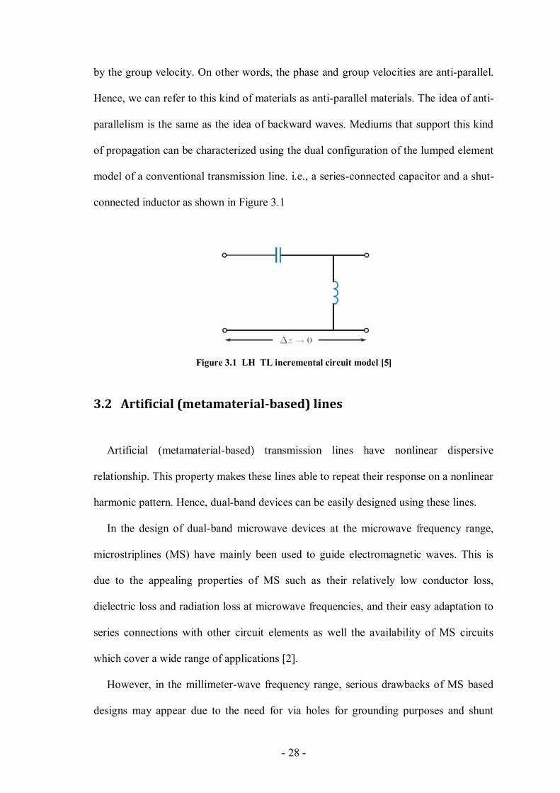
of propagation can be characterized using the dual configuration of the lumped element
model of a conventional transmission line. i.e., a series-connected capacitor and a shut-
connected inductor as shown in Figure 3.1
Figure 3.1 LH TL incremental circuit model [5]
3.2 Artificial (metamaterial-based) lines
Artificial (metamaterial-based) transmission lines have nonlinear dispersive
relationship. This property makes these lines able to repeat their response on a nonlinear
harmonic pattern. Hence, dual-band devices can be easily designed using these lines.
In the design of dual-band microwave devices at the microwave frequency range,
microstriplines (MS) have mainly been used to guide electromagnetic waves. This is
due to the appealing properties of MS such as their relatively low conductor loss,
dielectric loss and radiation loss at microwave frequencies, and their easy adaptation to
series connections with other circuit elements as well the availability of MS circuits
which cover a wide range of applications [2].
However, in the millimeter-wave frequency range, serious drawbacks of MS based
designs may appear due to the need for via holes for grounding purposes and shunt

- 29 -
connections. These via holes are rather costly to form, irreparable during fabrication,
and may degrade the circuit performance, especially at higher frequencies, due to the
parasitic inductance resulting from these holes.
Coplanar waveguides (CPW) have many advantages over microstrip lines as
mentioned in the next section. Hence, producing new designs based on CPW artificial
(left-handed) transmission lines would add extra appealing features to the new devices
which utilize these lines. [3], [4].
Surface mount technology (SMT) is the dominant technology used to produce
metamaterial based MW components because passive elements based on this
technology have fixed lumped values for a proper range of frequencies [5]. Therefore,
these elements are suitable for the design of dual-band circuits, in which the LE values
at the two center band frequencies should be constant. However, there are several
limitations related to the usage of SMT elements. Hence, distributed components (based
on CPW TLs in our case) which have almost constant performance over a wide range of
frequencies can be considered as better candidates for dual and wide band circuits.
3.3 Advantages of coplanar waveguide-based elements
The dominant mode in CPW transmission lines is an even quasi-TEM mode, called a
CPW mode. The electric fields of this mode in the two adjacent CPW slots are opposite
to each other. Hence, CPW operating in the CPW mode has low frequency dispersion
and low radiation loss which makes CPW suitable for wide band circuit applications.
Most of metamaterial units and devices are based on microstrip transmission lines
[6]-[10]. These lines may contain drilled via holes for grounding purposes. This will
make shunt as well as series surface mounting of active and passive devices more
difficult. In addition, the relatively high radiation loss and high frequency dispersion of
- 30 -
microstrip lines relative to CPW in both the microwave and millimeterwave frequency
ranges makes CPW technology an excellent candidate for metamaterials based
elements. These as well as several other advantages [3] make CPW more convenient for
our proposed microwave devices.
3.4 Theory of composite right/lift handed transmission lines
The first practical metamaterial saw the light at the beginning of the 21 century, and
more specifically in the year 2000 by Smith et al [11]. Their contribution was based on
the work of Pendry et al. [12] who produced two types of materials. One having
negative permittivity/positive permeability and the other one has positive
permittivity/negative permeability. Both materials operate at the MW range. Smith
combines the two aforementioned structures, namely: the thin wire (TW) and the split-
ring resonator (SRR), respectively, to obtain a new artificial material with negative
permittivity and permeability. Moreover, he introduces plasmonic expressions for the
permittivity and the permeability of these structures. These expressions are related to
the dimensions of the proposed materials and their operating frequencies [11].
In physics, backward waves (BWs) are well-know from the 1940s. They represent
the antiparallel phase and group velocities phenomenon in some materials. The behavior
of this kind of materials can be characterized by the following equivalent circuit model
(Figure 3.2). However, these materials in general have a cell size dimension of λ/2 or
n×λ/2, which makes the diffraction/scattering phenomena the dominant propagation
mechanism. Hence, we can't represent conventional BW materials using εr and μr. In
contrary, refraction is the main propagation mechanism in metamaterials due to their
smaller size. Hence, εr and μr can be used to represent these materials.
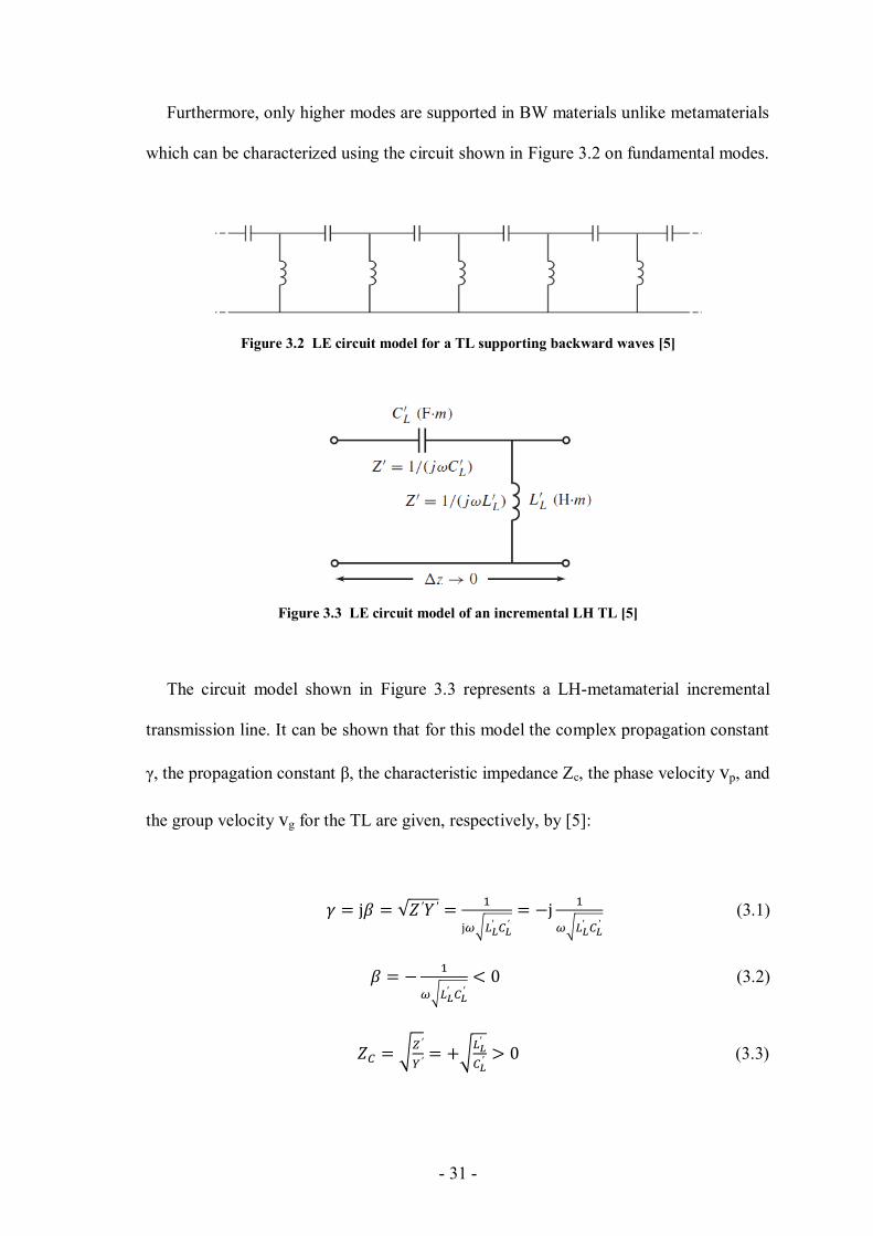
- 31 -
Furthermore, only higher modes are supported in BW materials unlike metamaterials
which can be characterized using the circuit shown in Figure 3.2 on fundamental modes.
Figure 3.2 LE circuit model for a TL supporting backward waves [5]
Figure 3.3 LE circuit model of an incremental LH TL [5]
The circuit model shown in Figure 3.3 represents a LH-metamaterial incremental
transmission line. It can be shown that for this model the complex propagation constant
γ, the propagation constant β, the characteristic impedance Zc, the phase velocity vp, and
the group velocity vg for the TL are given, respectively, by [5]:
(3.1)
(3.2)
(3.3)
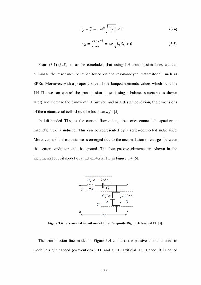
- 32 -
(3.4)
(3.5)
From (3.1)-(3.5), it can be concluded that using LH transmission lines we can
eliminate the resonance behavior found on the resonant-type metamaterial, such as
SRRs. Moreover, with a proper choice of the lumped elements values which built the
LH TL, we can control the transmission losses (using a balance structures as shown
later) and increase the bandwidth. However, and as a design condition, the dimensions
of the metamaterial cells should be less than λg/4 [5].
In left-handed TLs, as the current flows along the series-connected capacitor, a
magnetic flux is induced. This can be represented by a series-connected inductance.
Moreover, a shunt capacitance is emerged due to the accumulation of charges between
the center conductor and the ground. The four passive elements are shown in the
incremental circuit model of a metamaterial TL in Figure 3.4 [5].
Figure 3.4 Incremental circuit model for a Composite Right/left handed TL [5].
The transmission line model in Figure 3.4 contains the passive elements used to
model a right handed (conventional) TL and a LH artificial TL. Hence, it is called
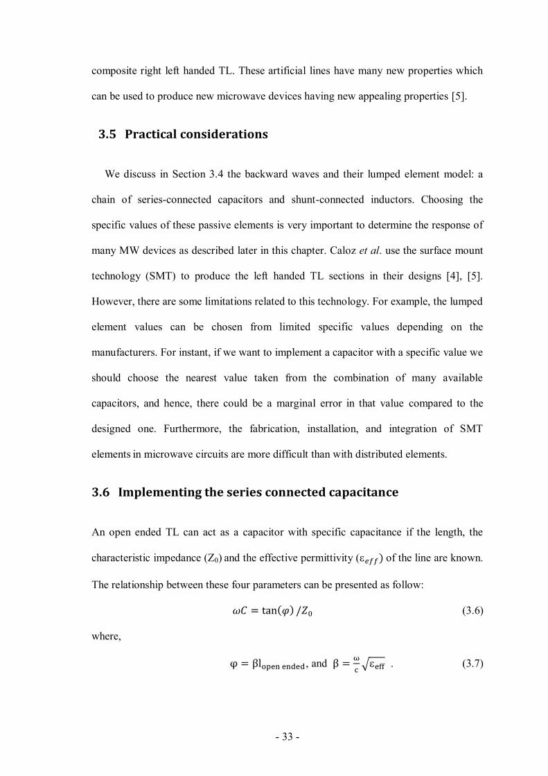
- 33 -
composite right left handed TL. These artificial lines have many new properties which
can be used to produce new microwave devices having new appealing properties [5].
3.5 Practical considerations
We discuss in Section 3.4 the backward waves and their lumped element model: a
chain of series-connected capacitors and shunt-connected inductors. Choosing the
specific values of these passive elements is very important to determine the response of
many MW devices as described later in this chapter. Caloz et al. use the surface mount
technology (SMT) to produce the left handed TL sections in their designs [4], [5].
However, there are some limitations related to this technology. For example, the lumped
element values can be chosen from limited specific values depending on the
manufacturers. For instant, if we want to implement a capacitor with a specific value we
should choose the nearest value taken from the combination of many available
capacitors, and hence, there could be a marginal error in that value compared to the
designed one. Furthermore, the fabrication, installation, and integration of SMT
elements in microwave circuits are more difficult than with distributed elements.
3.6 Implementing the series connected capacitance
An open ended TL can act as a capacitor with specific capacitance if the length, the
characteristic impedance (Z0) and the effective permittivity ( of the line are known.
The relationship between these four parameters can be presented as follow:
(3.6)
where,
, and
. (3.7)
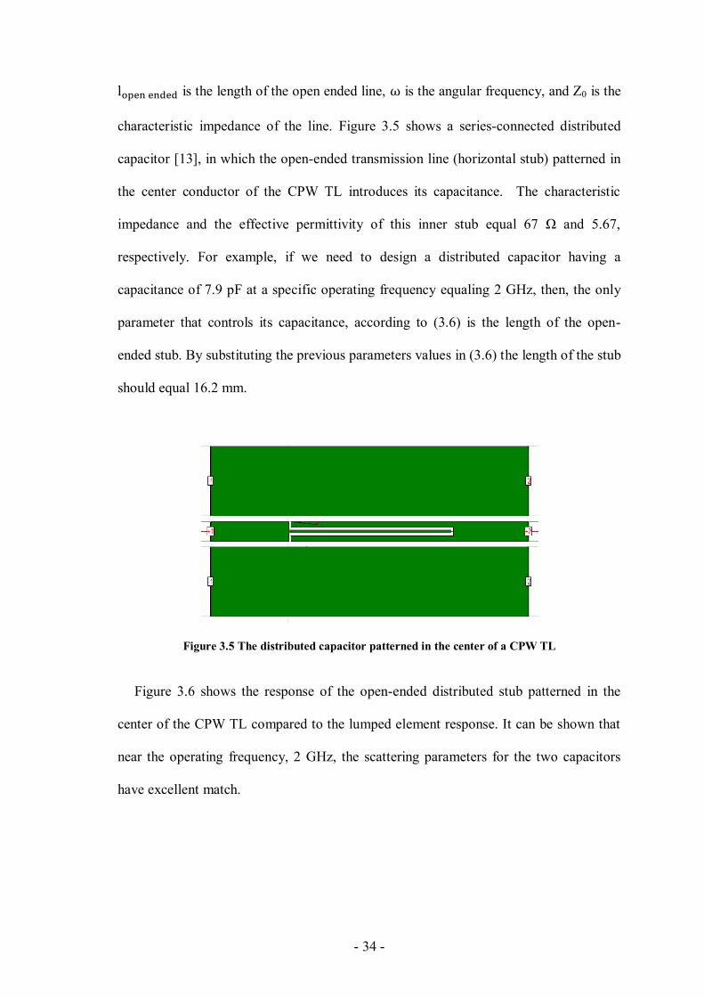
- 34 -
is the length of the open ended line, is the angular frequency, and Z0 is the
characteristic impedance of the line. Figure 3.5 shows a series-connected distributed
capacitor [13], in which the open-ended transmission line (horizontal stub) patterned in
the center conductor of the CPW TL introduces its capacitance. The characteristic
impedance and the effective permittivity of this inner stub equal 67 Ω and 5.67,
respectively. For example, if we need to design a distributed capacitor having a
capacitance of 7.9 pF at a specific operating frequency equaling 2 GHz, then, the only
parameter that controls its capacitance, according to (3.6) is the length of the open-
ended stub. By substituting the previous parameters values in (3.6) the length of the stub
should equal 16.2 mm.
Figure 3.5 The distributed capacitor patterned in the center of a CPW TL
Figure 3.6 shows the response of the open-ended distributed stub patterned in the
center of the CPW TL compared to the lumped element response. It can be shown that
near the operating frequency, 2 GHz, the scattering parameters for the two capacitors
have excellent match.
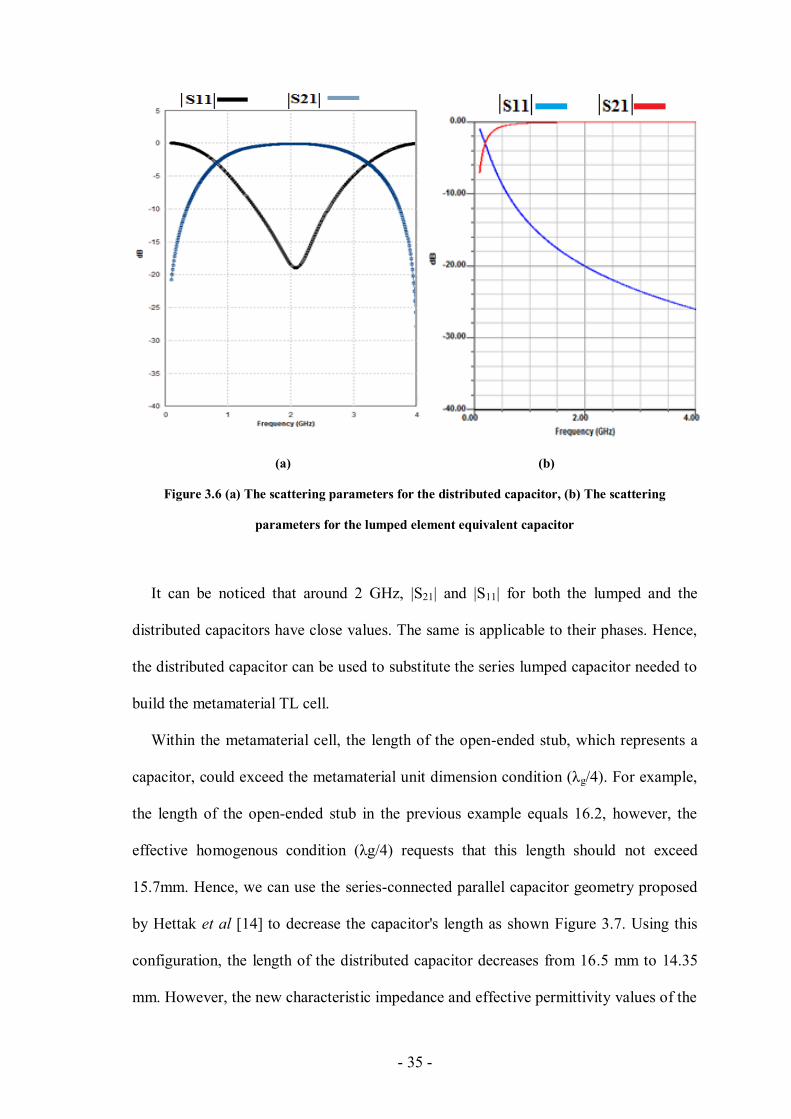
- 35 -
(a) (b)
Figure 3.6 (a) The scattering parameters for the distributed capacitor, (b) The scattering
parameters for the lumped element equivalent capacitor
It can be noticed that around 2 GHz, |S21| and |S11| for both the lumped and the
distributed capacitors have close values. The same is applicable to their phases. Hence,
the distributed capacitor can be used to substitute the series lumped capacitor needed to
build the metamaterial TL cell.
Within the metamaterial cell, the length of the open-ended stub, which represents a
capacitor, could exceed the metamaterial unit dimension condition (λg/4). For example,
the length of the open-ended stub in the previous example equals 16.2, however, the
effective homogenous condition (λg/4) requests that this length should not exceed
15.7mm. Hence, we can use the series-connected parallel capacitor geometry proposed
by Hettak et al [14] to decrease the capacitor's length as shown Figure 3.7. Using this
configuration, the length of the distributed capacitor decreases from 16.5 mm to 14.35
mm. However, the new characteristic impedance and effective permittivity values of the
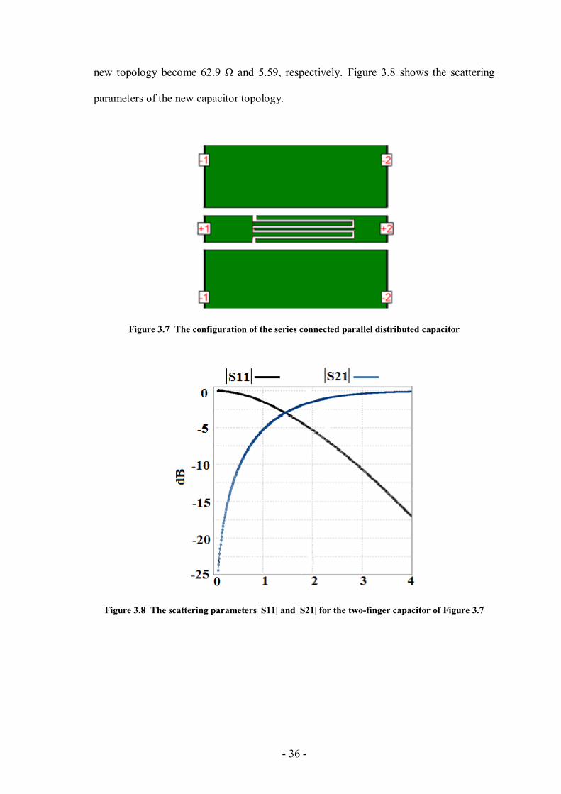
- 36 -
new topology become 62.9 Ω and 5.59, respectively. Figure 3.8 shows the scattering
parameters of the new capacitor topology.
Figure 3.7 The configuration of the series connected parallel distributed capacitor
Figure 3.8 The scattering parameters |S11| and |S21| for the two-finger capacitor of Figure 3.7

- 37 -
3.7 Implementing the shunt inductor
A similar design procedure to the previous one can be applied to design a distributed
inductor. However, the stub in the center of the CPW TL should be short-ended [13].
The ground plane at which the stub is short-ended is considered infinite for simplicity.
The relationship between the operating frequency, the effective permittivity, the
characteristic impedance, and the length of the short ended stub is determined by [15]:
(3.8)
Figure 3.9 shows the shunt-connected short-ended stub which represents a shunt
connected distributed inductor. All the dimensions are determined using the (3.8).
Figure 3.10 shows the response of the distributed inductance.
Figure 3.9 The distributed shunt-connected distributed inductor
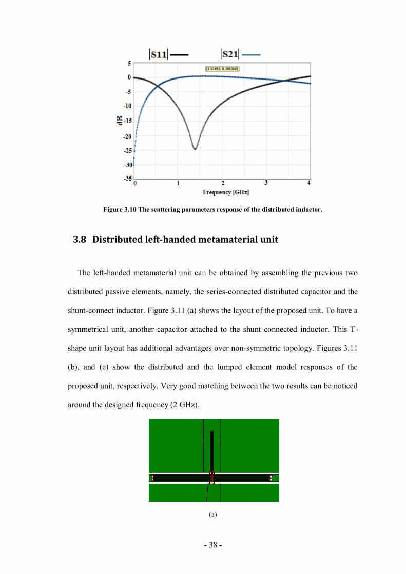
- 38 -
Figure 3.10 The scattering parameters response of the distributed inductor.
3.8 Distributed left-handed metamaterial unit
The left-handed metamaterial unit can be obtained by assembling the previous two
distributed passive elements, namely, the series-connected distributed capacitor and the
shunt-connect inductor. Figure 3.11 (a) shows the layout of the proposed unit. To have a
symmetrical unit, another capacitor attached to the shunt-connected inductor. This T-
shape unit layout has additional advantages over non-symmetric topology. Figures 3.11
(b), and (c) show the distributed and the lumped element model responses of the
proposed unit, respectively. Very good matching between the two results can be noticed
around the designed frequency (2 GHz).
(a)
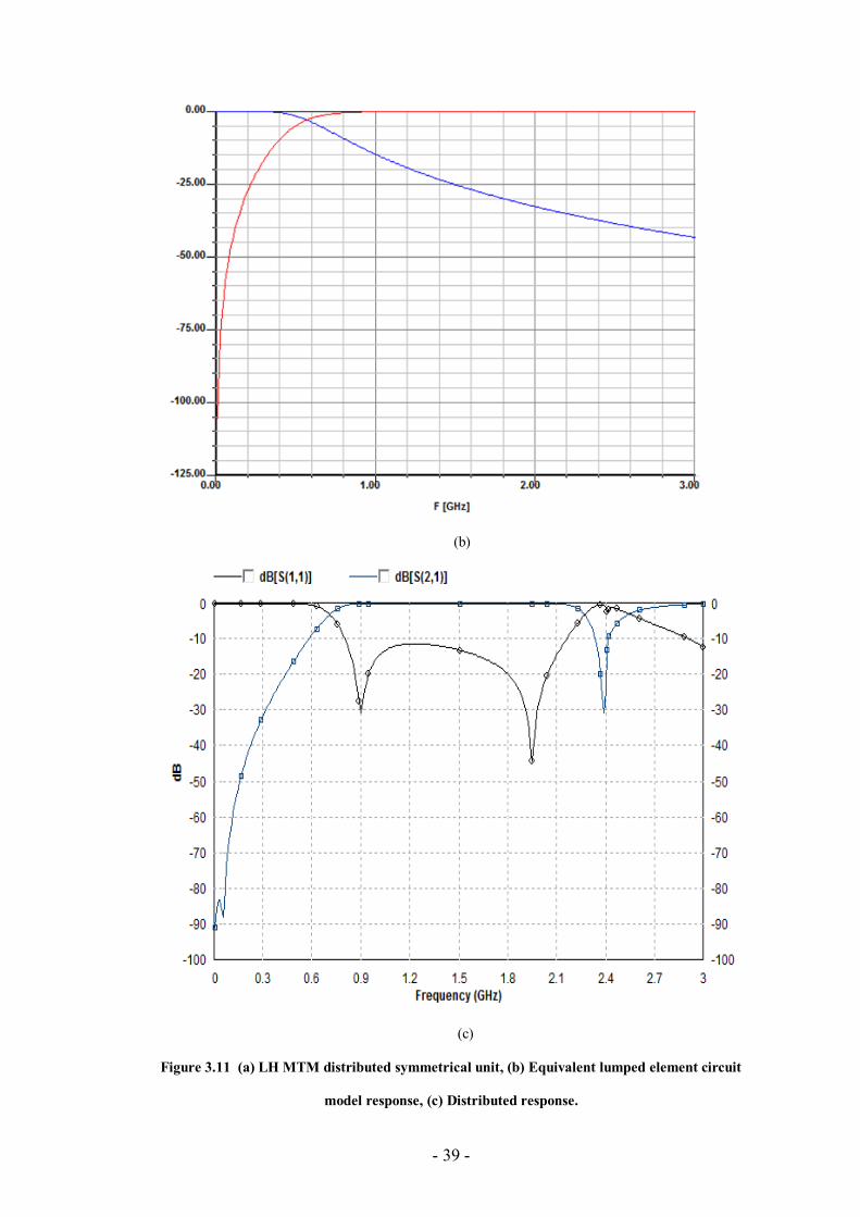
- 39 -
(b)
(c)
Figure 3.11 (a) LH MTM distributed symmetrical unit, (b) Equivalent lumped element circuit
model response, (c) Distributed response.
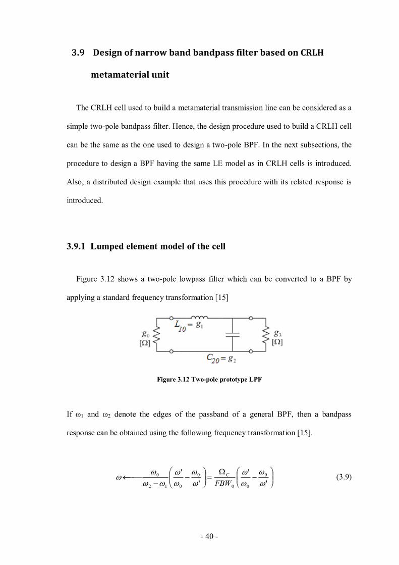
- 40 -
3.9 Design of narrow band bandpass filter based on CRLH
metamaterial unit
The CRLH cell used to build a metamaterial transmission line can be considered as a
simple two-pole bandpass filter. Hence, the design procedure used to build a CRLH cell
can be the same as the one used to design a two-pole BPF. In the next subsections, the
procedure to design a BPF having the same LE model as in CRLH cells is introduced.
Also, a distributed design example that uses this procedure with its related response is
introduced.
3.9.1 Lumped element model of the cell
Figure 3.12 shows a two-pole lowpass filter which can be converted to a BPF by
applying a standard frequency transformation [15]
Figure 3.12 Two-pole prototype LPF
If ω1 and ω2 denote the edges of the passband of a general BPF, then a bandpass
response can be obtained using the following frequency transformation [15].
'
'
'
' 0
00
0
012
0
FBW
C (3.9)
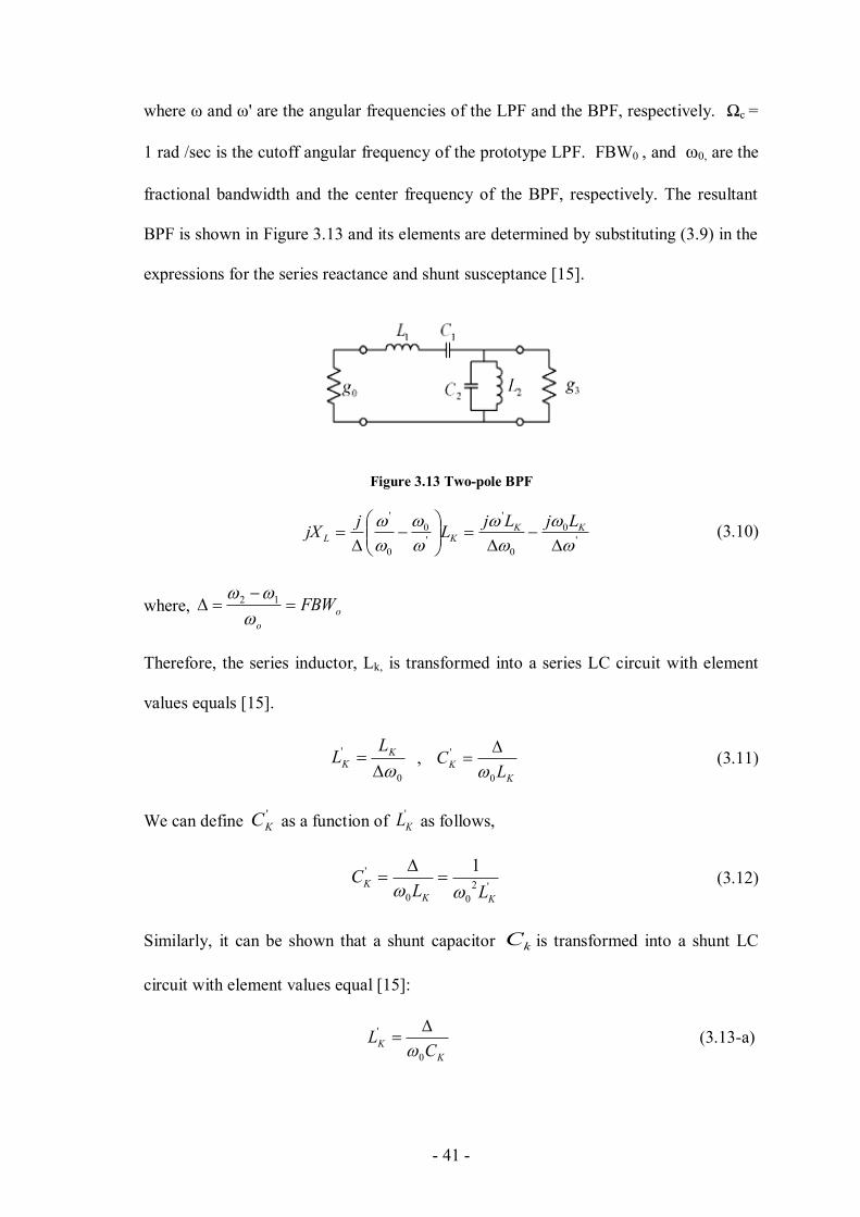
- 41 -
where ω and ω' are the angular frequencies of the LPF and the BPF, respectively. Ωc =
1 rad /sec is the cutoff angular frequency of the prototype LPF. FBW0 , and ω0, are the
fractional bandwidth and the center frequency of the BPF, respectively. The resultant
BPF is shown in Figure 3.13 and its elements are determined by substituting (3.9) in the
expressions for the series reactance and shunt susceptance [15].
Figure 3.13 Two-pole BPF
'
0
0
'
'
0
0
'
KK
KL
LjLjL
jjX (3.10)
where, o
o
FBW
12
Therefore, the series inductor, Lk, is transformed into a series LC circuit with element
values equals [15].
0
'
K
K
LL ,
K
KL
C0
'
(3.11)
We can define '
KC as a function of '
KL as follows,
'2
00
' 1
KK
KLL
C
(3.12)
Similarly, it can be shown that a shunt capacitor kC is transformed into a shunt LC
circuit with element values equal [15]:
K
KC
L0
'
(3.13-a)
- 42 -
0
'
K
K
CC (3.13-b)
From (3.5-a)
0
' K
KL
C
(3.13-c)
Hence, (3.5-b) becomes
2
0
'
' 1
K
KL
C (3.13-d)
3.9.2 Design example of a bandpass filter using one CRLH unit
A bandpass Chebyshev filter (acting as a CRLH cell) centered at 5 GHz with a ripple in
the passband of 0.01 dB is introduced in this section. From [16], the elements of the low
pass prototype of Figure 3.12 are given by: g0=1, g1=0.4488, g2=0.4077 and g3=1.1007.
The desired fractional bandwidth of the passband filter is 0.3, i.e., the equal-ripple
bandwidths of the passband is 1.5 GHz. The values of the lumped elements of the BPF
can be found using (3.10) and (3.13) as shown in Table 3.1
Table 3.1 The lumped elements values of the circuit configurations of the BPF shown in Figure 3.13
CL = 0.425 pF LL=1.171 nH CR= 0.865 pF LR =2.381 nH
The series-connected series LC resonator is realized using the proposed resonator in
[16] while the shunt-connected shunt resonator implemented using a short ended λ/4
stub.
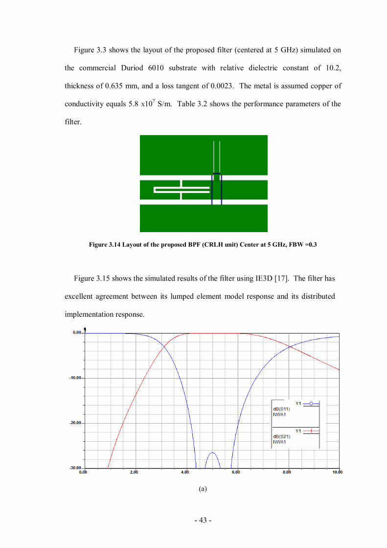
- 43 -
Figure 3.3 shows the layout of the proposed filter (centered at 5 GHz) simulated on
the commercial Duriod 6010 substrate with relative dielectric constant of 10.2,
thickness of 0.635 mm, and a loss tangent of 0.0023. The metal is assumed copper of
conductivity equals 5.8 X10⁷ S/m. Table 3.2 shows the performance parameters of the
filter.
Figure 3.14 Layout of the proposed BPF (CRLH unit) Center at 5 GHz, FBW =0.3
Figure 3.15 shows the simulated results of the filter using IE3D [17]. The filter has
excellent agreement between its lumped element model response and its distributed
implementation response.
(a)
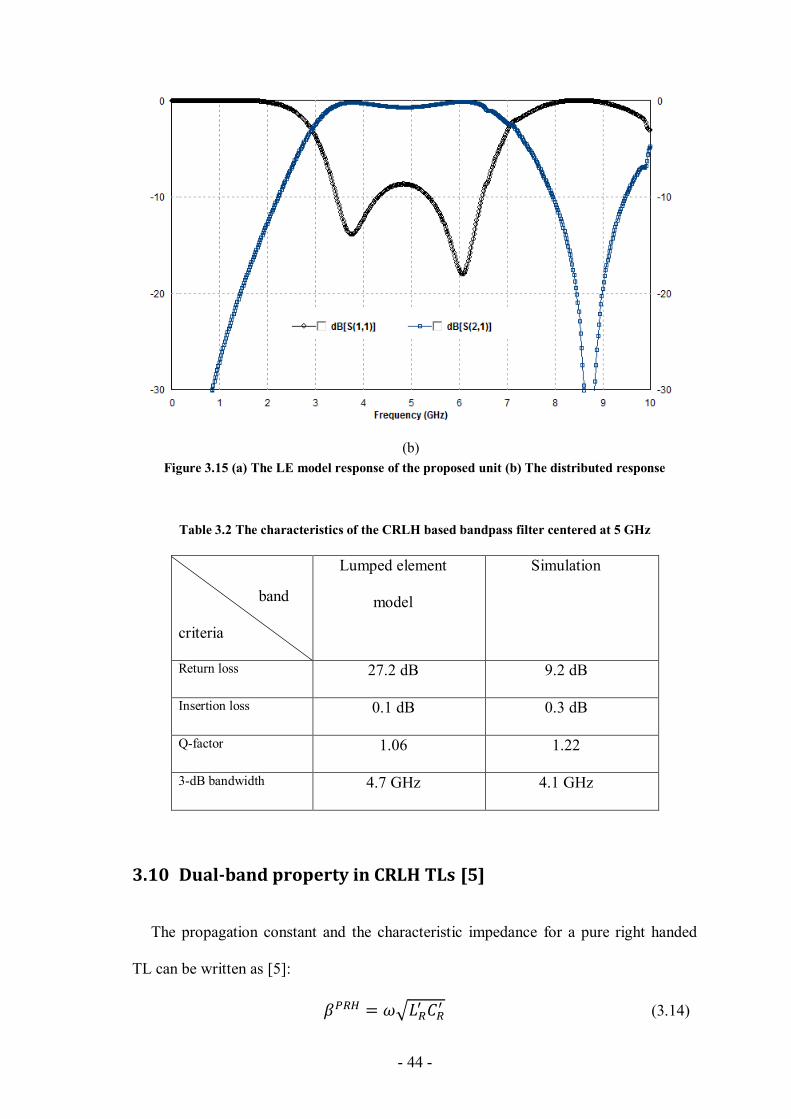
- 44 -
(b)
Figure 3.15 (a) The LE model response of the proposed unit (b) The distributed response
Table 3.2 The characteristics of the CRLH based bandpass filter centered at 5 GHz
band
criteria
Lumped element
model
Simulation
Return loss 27.2 dB 9.2 dB
Insertion loss 0.1 dB 0.3 dB
Q-factor 1.06 1.22
3-dB bandwidth 4.7 GHz 4.1 GHz
3.10 Dual-band property in CRLH TLs [5]
The propagation constant and the characteristic impedance for a pure right handed
TL can be written as [5]:
(3.14)
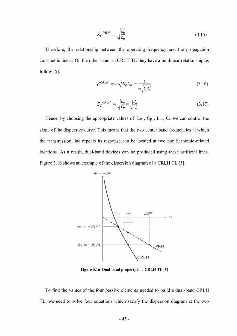
- 45 -
(3.15)
Therefore, the relationship between the operating frequency and the propagation
constant is linear. On the other hand, in CRLH TL they have a nonlinear relationship as
follow [5]:
(3.16)
=
(3.17)
Hence, by choosing the appropriate values of LR , CR , LL , CL we can control the
slope of the dispersive curve. This means that the two center band frequencies at which
the transmission line repeats its response can be located at two non harmonic-related
locations. As a result, dual-band devices can be produced using these artificial lines.
Figure 3.16 shows an example of the dispersion diagram of a CRLH TL [5].
Figure 3.16 Dual-band property in a CRLH TL [5]
To find the values of the four passive elements needed to build a dual-band CRLH
TL, we need to solve four equations which satisfy the dispersion diagram at the two
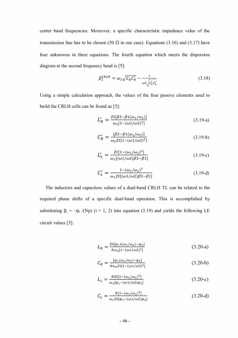
- 46 -
center band frequencies. Moreover, a specific characteristic impedance value of the
transmission line has to be chosen (50 Ω in our case). Equations (3.16) and (3.17) have
four unknowns in three equations. The fourth equation which meets the dispersion
diagram at the second frequency band is [5]:
(3.18)
Using a simple calculation approach, the values of the four passive elements used to
build the CRLH cells can be found as [5]:
(3.19-a)
(3.19-b)
(3.19-c)
(3.19-d)
The inductors and capacitors values of a dual-band CRLH TL can be related to the
required phase shifts of a specific dual-band operation. This is accomplished by
substituting βi = −φi /(Np) (i = 1, 2) into equation (3.19) and yields the following LE
circuit values [5]:
(3.20-a)
(3.20-b)
(3.20-c)
(3.20-d)

- 47 -
3.11 Dual-band quarter wavelength TLs and stubs [5]
Many microwave devices consist of quarter-wavelength TL sections in the form of
parallel stubs, impedance inverters, etc. For example, a conventional HBLC has four
quarter-wavelength TLs. The input power for the HBLCs is split equally at the two
output ports at the operating frequency. This response repeat itself each odd-multiple
harmonic. i.e., the next center band frequency at which a conventional TL provides a
similar response is located at one additional full turn in the Smith chart. On other words,
the phase difference between f1 and f2=3×f1 equals π.
On the other hand, CRLH TL can repeat its response at a frequency not necessarily
the harmonic of the dominant operating frequency. This can be achieved by properly
choosing the values of the passive elements of the CRLH cells.
For quarter wavelength application, we can choose any two values of φ1 and φ2
which make a π difference at and , for example, let φ1= -π/2 and φ2 =-3π/2,
hence, equation (3.20) becomes [5]:
(3.21-a)
(3.21-b)
(3.21-c)
(3.21-d)
The balanced CRLH cell shown in Figure 3.4 can be presented as shown in the
circuit model of Figure 3.17 [5].
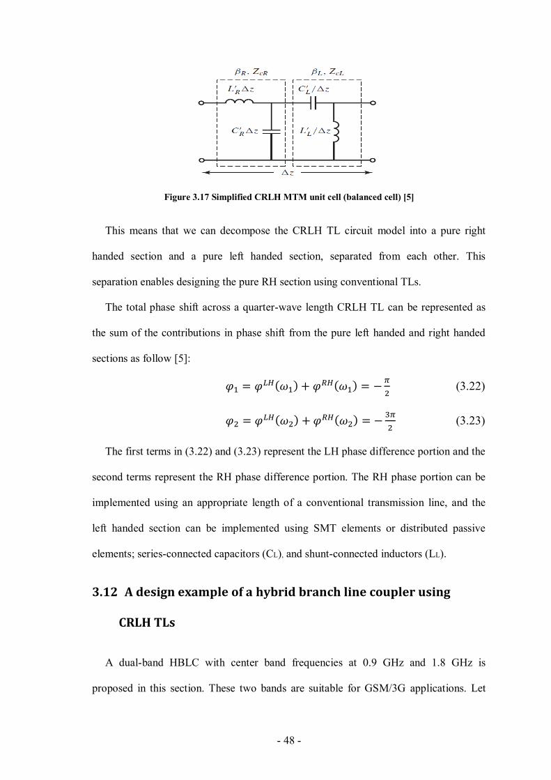
- 48 -
Figure 3.17 Simplified CRLH MTM unit cell (balanced cell) [5]
This means that we can decompose the CRLH TL circuit model into a pure right
handed section and a pure left handed section, separated from each other. This
separation enables designing the pure RH section using conventional TLs.
The total phase shift across a quarter-wave length CRLH TL can be represented as
the sum of the contributions in phase shift from the pure left handed and right handed
sections as follow [5]:
(3.22)
(3.23)
The first terms in (3.22) and (3.23) represent the LH phase difference portion and the
second terms represent the RH phase difference portion. The RH phase portion can be
implemented using an appropriate length of a conventional transmission line, and the
left handed section can be implemented using SMT elements or distributed passive
elements; series-connected capacitors (CL), and shunt-connected inductors (LL).
3.12 A design example of a hybrid branch line coupler using
CRLH TLs
A dual-band HBLC with center band frequencies at 0.9 GHz and 1.8 GHz is
proposed in this section. These two bands are suitable for GSM/3G applications. Let
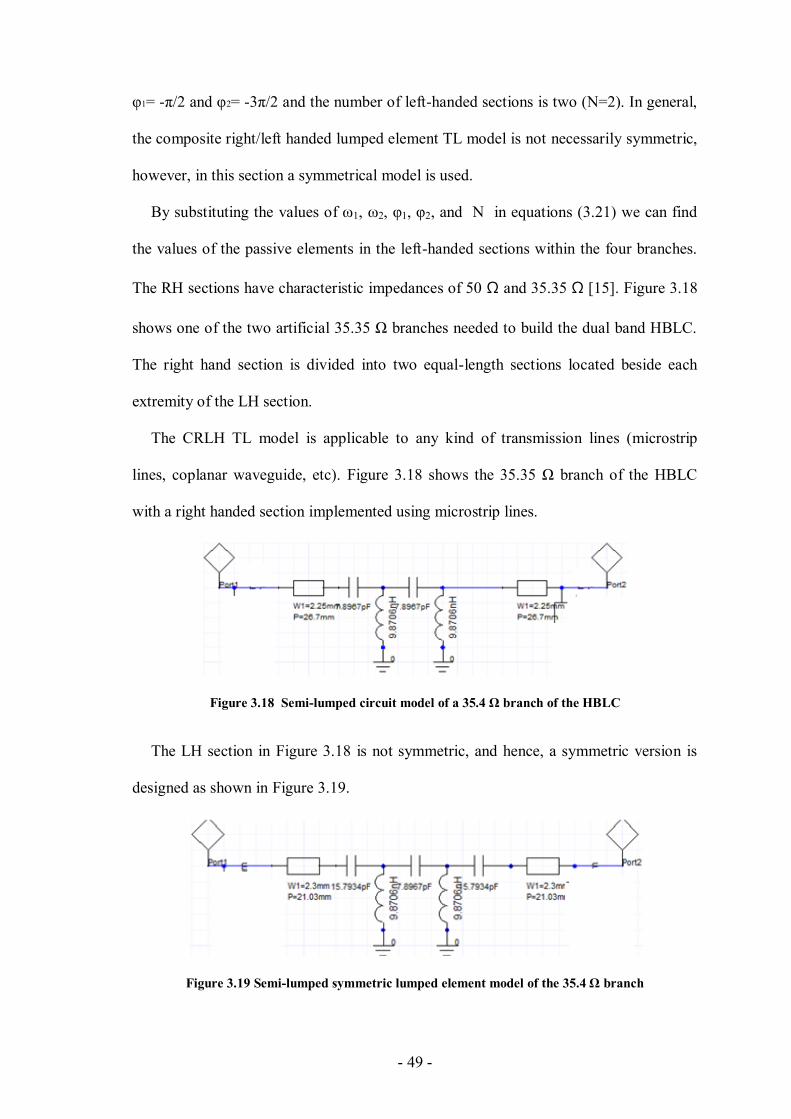
- 49 -
φ1= -π/2 and φ2= -3π/2 and the number of left-handed sections is two (N=2). In general,
the composite right/left handed lumped element TL model is not necessarily symmetric,
however, in this section a symmetrical model is used.
By substituting the values of ω1, ω2, φ1, φ2, and N in equations (3.21) we can find
the values of the passive elements in the left-handed sections within the four branches.
The RH sections have characteristic impedances of 50 Ω and 35.35 Ω [15]. Figure 3.18
shows one of the two artificial 35.35 Ω branches needed to build the dual band HBLC.
The right hand section is divided into two equal-length sections located beside each
extremity of the LH section.
The CRLH TL model is applicable to any kind of transmission lines (microstrip
lines, coplanar waveguide, etc). Figure 3.18 shows the 35.35 Ω branch of the HBLC
with a right handed section implemented using microstrip lines.
Figure 3.18 Semi-lumped circuit model of a 35.4 Ω branch of the HBLC
The LH section in Figure 3.18 is not symmetric, and hence, a symmetric version is
designed as shown in Figure 3.19.
Figure 3.19 Semi-lumped symmetric lumped element model of the 35.4 Ω branch
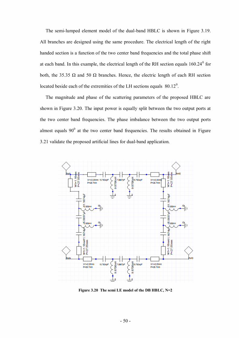
- 50 -
The semi-lumped element model of the dual-band HBLC is shown in Figure 3.19.
All branches are designed using the same procedure. The electrical length of the right
handed section is a function of the two center band frequencies and the total phase shift
at each band. In this example, the electrical length of the RH section equals 160.240 for
both, the 35.35 Ω and 50 Ω branches. Hence, the electric length of each RH section
located beside each of the extremities of the LH sections equals 80.120.
The magnitude and phase of the scattering parameters of the proposed HBLC are
shown in Figure 3.20. The input power is equally split between the two output ports at
the two center band frequencies. The phase imbalance between the two output ports
almost equals 900 at the two center band frequencies. The results obtained in Figure
3.21 validate the proposed artificial lines for dual-band application.
Figure 3.20 The semi LE model of the DB HBLC, N=2
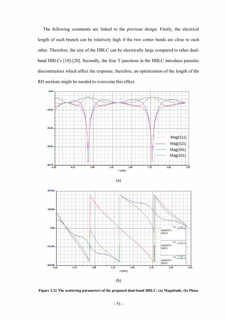
- 51 -
The following comments are linked to the previous design. Firstly, the electrical
length of each branch can be relatively high if the two center bands are close to each
other. Therefore, the size of the HBLC can be electrically large compared to other dual-
band HBLCs [18]-[20]. Secondly, the four T-junctions in the HBLC introduce parasitic
discontinuities which affect the response; therefore, an optimization of the length of the
RH sections might be needed to overcome this effect.
(a)
(b)
Figure 3.21 The scattering parameters of the proposed dual-band HBLC: (a) Magnitude, (b) Phase
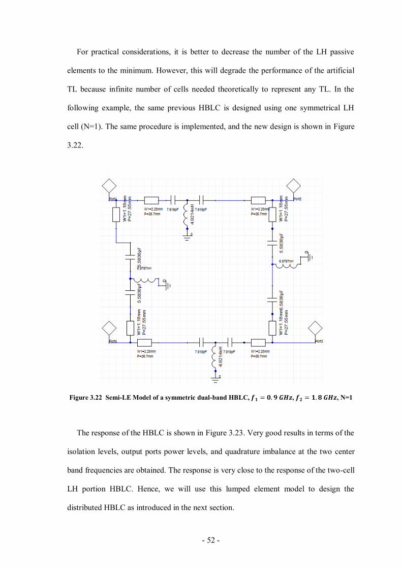
- 52 -
For practical considerations, it is better to decrease the number of the LH passive
elements to the minimum. However, this will degrade the performance of the artificial
TL because infinite number of cells needed theoretically to represent any TL. In the
following example, the same previous HBLC is designed using one symmetrical LH
cell (N=1). The same procedure is implemented, and the new design is shown in Figure
3.22.
Figure 3.22 Semi-LE Model of a symmetric dual-band HBLC, , , N=1
The response of the HBLC is shown in Figure 3.23. Very good results in terms of the
isolation levels, output ports power levels, and quadrature imbalance at the two center
band frequencies are obtained. The response is very close to the response of the two-cell
LH portion HBLC. Hence, we will use this lumped element model to design the
distributed HBLC as introduced in the next section.
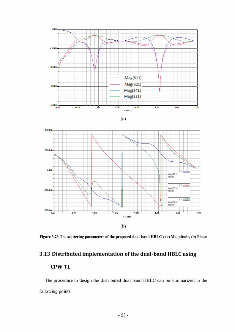
- 53 -
(a)
(b)
Figure 3.23 The scattering parameters of the proposed dual-band HBLC : (a) Magnitude, (b) Phase
3.13 Distributed implementation of the dual-band HBLC using
CPW TL
The procedure to design the distributed dual-band HBLC can be summarized in the
following points:
- 54 -
1) Determine the appropriate characteristic impedances of the four branches. 50 Ω and
35.35 Ω branches are usually used because the input ports of the measuring tools have
input impedances equal 50 Ω.
2) Choose the center band frequencies at which the HBLC gives its response.
3) Choose the appropriate number of segments (N) for the left handed sections.
4) Find the values of CL and LL for each branch using (3.21), then, find the dimensions of
the distributed capacitors (CL) and the distributed inductors (LL) using (3.6) - (3.8)
5) To find the dimensions of the distributed passive elements we need to know εeff and Z0
for the open ended capacitive and short ended inductive stubs.
6) The distributed response for each branch has to be compared with its equivalent
lumped element model response. Optimizations in the lengths of the open-ended stubs,
short ended stubs, and the lengths of the right handed sections can be done in order to
match the two responses.
7) Assemble all parts (superposition) to get the whole structure, and re-optimize all
branches.
8) Because the dimensions of the distributed LH section: CL and LL are function of
frequency. It will be difficult to reflect the same fixed lumped element values at ω1 and
ω2 exactly. For this reason, the distributed element will be designed at the first
frequency band in the next section, then, it will be designed at the average value of the
two center band frequencies.
3.14 Design example of single-band distributed hybrid branch
line coupler using CRLH TLs
A distributed single-band HBLC with center band frequency at 0.93 GHz is
introduced in this section. Two similar 50 Ω, and 35.4 Ω branches are designed. The
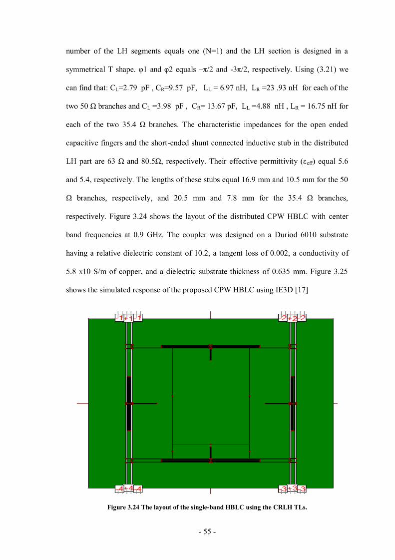
- 55 -
number of the LH segments equals one (N=1) and the LH section is designed in a
symmetrical T shape. φ1 and φ2 equals –π/2 and -3π/2, respectively. Using (3.21) we
can find that: CL= 97.2 pF , CR= 270. pF, LL = 6.97 nH, LR = 92 .22 nH for each of the
two 50 Ω branches and CL = 2723 pF , CR= 13.67 pF, LL = 8733 nH , LR = 16.75 nH for
each of the two 35.4 Ω branches. The characteristic impedances for the open ended
capacitive fingers and the short-ended shunt connected inductive stub in the distributed
LH part are 63 Ω and 80.5Ω, respectively. Their effective permittivity (εeff) equal 5.6
and 5.4, respectively. The lengths of these stubs equal 16.9 mm and 10.5 mm for the 50
Ω branches, respectively, and 20.5 mm and 7.8 mm for the 35.4 Ω branches,
respectively. Figure 3.24 shows the layout of the distributed CPW HBLC with center
band frequencies at 0.9 GHz. The coupler was designed on a Duriod 6010 substrate
having a relative dielectric constant of 10.2, a tangent loss of 0.002, a conductivity of
5.8 X10 S/m of copper, and a dielectric substrate thickness of 0.635 mm. Figure 3.25
shows the simulated response of the proposed CPW HBLC using IE3D [17]
Figure 3.24 The layout of the single-band HBLC using the CRLH TLs.
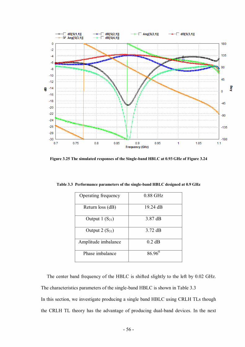
- 56 -
Figure 3.25 The simulated responses of the Single-band HBLC at 0.93 GHz of Figure 3.24
Table 3.3 Performance parameters of the single-band HBLC designed at 0.9 GHz
Operating frequency 0.88 GHz
Return loss (dB) 19.24 dB
Output 1 (S21) 3.87 dB
Output 2 (S31) 3.72 dB
Amplitude imbalance 0.2 dB
Phase imbalance 86.960
The center band frequency of the HBLC is shifted slightly to the left by 0.02 GHz.
The characteristics parameters of the single-band HBLC is shown in Table 3.3
In this section, we investigate producing a single band HBLC using CRLH TLs though
the CRLH TL theory has the advantage of producing dual-band devices. In the next
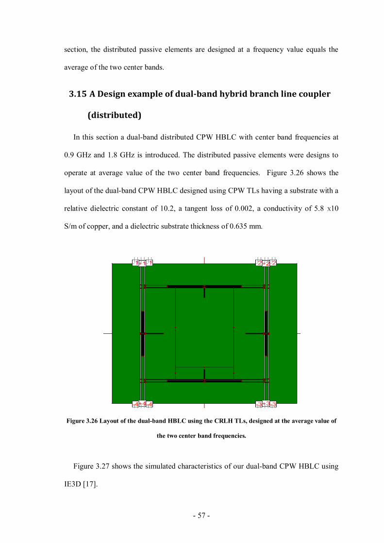
- 57 -
section, the distributed passive elements are designed at a frequency value equals the
average of the two center bands.
3.15 A Design example of dual-band hybrid branch line coupler
(distributed)
In this section a dual-band distributed CPW HBLC with center band frequencies at
0.9 GHz and 1.8 GHz is introduced. The distributed passive elements were designs to
operate at average value of the two center band frequencies. Figure 3.26 shows the
layout of the dual-band CPW HBLC designed using CPW TLs having a substrate with a
relative dielectric constant of 10.2, a tangent loss of 0.002, a conductivity of 5.8 X10
S/m of copper, and a dielectric substrate thickness of 0.635 mm.
Figure 3.26 Layout of the dual-band HBLC using the CRLH TLs, designed at the average value of
the two center band frequencies.
Figure 3.27 shows the simulated characteristics of our dual-band CPW HBLC using
IE3D [17].
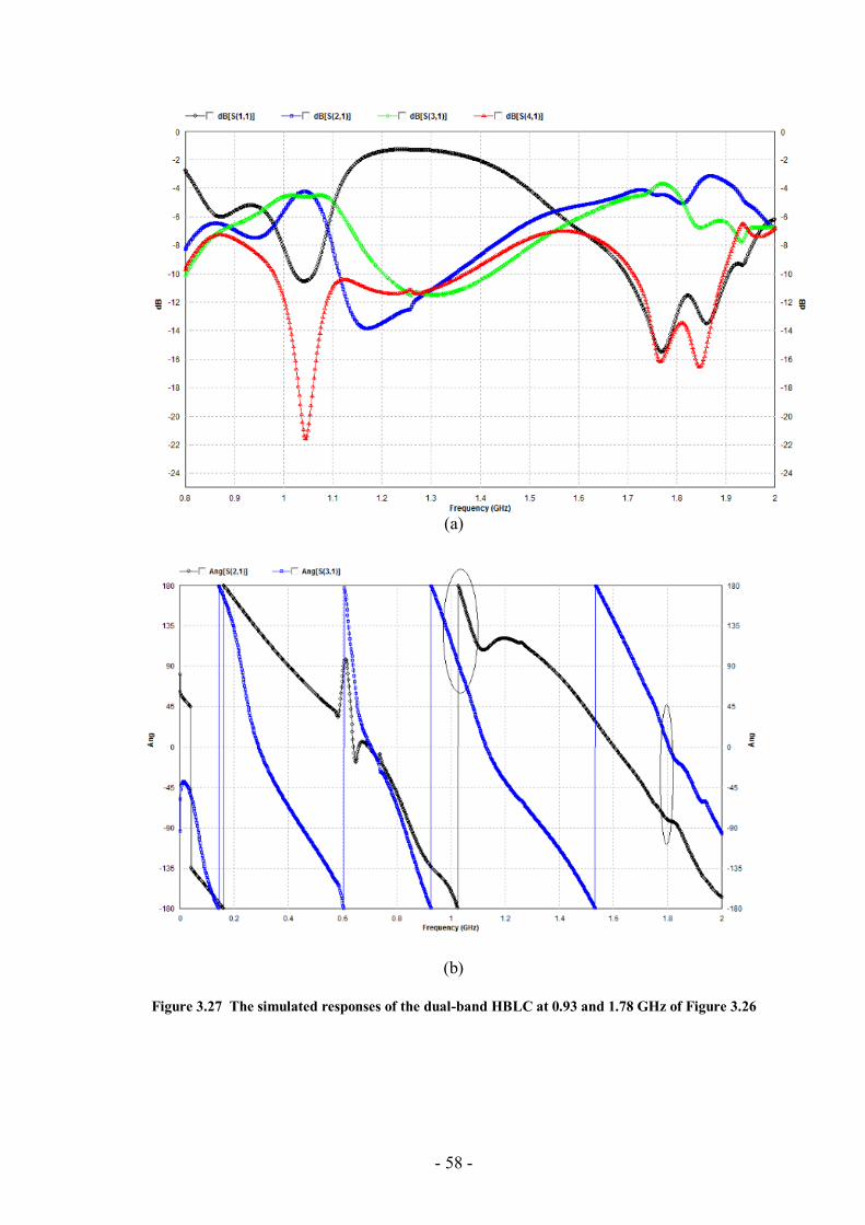
- 58 -
(a)
(b)
Figure 3.27 The simulated responses of the dual-band HBLC at 0.93 and 1.78 GHz of Figure 3.26
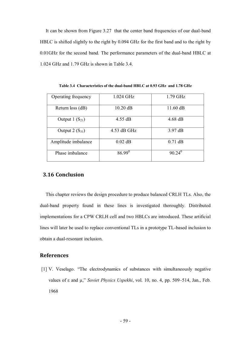
- 59 -
It can be shown from Figure 3.27 that the center band frequencies of our dual-band
HBLC is shifted slightly to the right by 0.094 GHz for the first band and to the right by
0.01GHz for the second band. The performance parameters of the dual-band HBLC at
1.024 GHz and 1.79 GHz is shown in Table 3.4.
Table 3.4 Characteristics of the dual-band HBLC at 0.93 GHz and 1.78 GHz
Operating frequency 1.024 GHz 1.79 GHz
Return loss (dB) 10.20 dB 11.60 dB
Output 1 (S21) 4.55 dB 4.68 dB
Output 2 (S31) 4.53 dB GHz 3.97 dB
Amplitude imbalance 0.02 dB 0.71 dB
Phase imbalance 86.990 90.24
0
3.16 Conclusion
This chapter reviews the design procedure to produce balanced CRLH TLs. Also, the
dual-band property found in these lines is investigated thoroughly. Distributed
implementations for a CPW CRLH cell and two HBLCs are introduced. These artificial
lines will later be used to replace conventional TLs in a prototype TL-based inclusion to
obtain a dual-resonant inclusion.
References
[1] V. Veselago. “The electrodynamics of substances with simultaneously negative
values of ε and µ,” Soviet Physics Uspekhi, vol. 10, no. 4, pp. 509–514, Jan., Feb.
1968
- 60 -
[2] R.W. Jackson, "Consideration in the use of coplanar waveguide for millimeter
wave integrated circuits," IEEE Trans. On Microwave Theory and Techniques,
Vol.MTT-34, pp. 1450-1456, Dec.1986.
[3] C.P. Wen, "Coplanar Waveguide: A Surface Strip Transmission Line Suitable for
Nonreciprocal Gyromagnetic Device Applications," IEEE Trans. Microwave theory
tech., Vol.17, No.12, pp.1087-1090, Dec .1969.
[4] J. Browne," Broadband Amps Sport Coplanar Waveguide," Microwave RF, Vol.26,
No.2, pp.131-134, Feb. 1987.
[5] C. Caloz and T. Itoh, Electromagnetic Metamaterials, Transmission Line Theory
and Microwave Applications, Wiley and IEEE Press, Hoboken, NJ, 2005.
[6] Ming-Chun Tang; Shaoqiu Xiao; Bingzhong Wang; Jian Guan; Tianwei Deng,
"Improved Performance of a Microstrip Phased Array Using Broadband and Ultra-
Low-Loss Metamaterial Slabs," Antennas and Propagation Magazine, IEEE ,
vol.53, no.6, pp.31,41, Dec. 2011
[7] Wiwatcharagoses, N.; Chahal, P., "A novel reconfigurable metamaterial unit
cell based Composite Right/Left Handed microstrip design," Antennas and
Propagation (APSURSI), 2011 IEEE International Symposium on , vol., no.,
pp.2954,2957, 3-8 July 2011
[8] Le-Wei Li; Ya-Nan Li; Tat Soon Yeo; Mosig, J.R.; Martin, O. J F, "A broadband
and high-gain metamaterial microstrip antenna," Applied Physics Letters , vol.96,
no.16, pp.164101,164101-3, Apr 2010
[9] Eccleston, K.W.; Junyao Zong, "Implementation of a Microstrip Square Planar -
Way Metamaterial Power Divider," Microwave Theory and Techniques, IEEE
Transactions on, vol.57, no.1, pp.189,195, Jan. 2009.
- 61 -
[10] Gil, I.; Bonache, J.; Garcia-Garcia, J.; Martin, F., "Tunable metamaterial
transmission lines based on varactor-loaded split-ring resonators," Microwave
Theory and Techniques, IEEE Transactions on , vol.54, no.6, pp.2665,2674, June
2006.
[11] D. R. Smith, W. J. Padilla, D. C. Vier, S. C. Nemat-Nasser, and S. Schultz.
“Composite medium with simultaneously negative permeability and permittivity,”
Phys. Rev. Lett., vol. 84, no. 18, pp. 4184–4187, May 2000.
[12] Pendry, J.B.; Holden, A.J.; Robbins, D.J.; Stewart, W.J.; , "Magnetism from
conductors and enhanced nonlinear phenomena," Microwave Theory and
Techniques, IEEE Transactions on , vol.47, no.11, pp.2075-2084, Nov 1999.
[13] N. Dib, L. Katehi, G. Ponchak, and R. Simons, “Theoretical and experimental
characterization of coplanar waveguide discontinuities for filter applications,” IEEE
Trans. Microwave Theory Tech., vol. 39, pp. 873–882, May 1991.
[14] D. M. Pozar, Microwave Engineering, 2nd ed. New York: Wiley, 1998.
[15] G. Matthaei, L. Young, and E. M. T. Jones, Microwave Filter, Impedance-
Matching Networks, and Coupling Structures. Norwood, MA: Artech House, 1980.
[16] K. Hettak, N.I Dib, A.-F.Sheta, and S.Toutain," A class of Novel Uniplanar
Series Resonators and Their Implementation in Original Applications," IEEE
Trans. Microwave Theory Tech., Vol.46, No.9, pp.1270-1276, Sept.1998.
[17] Zeland Software, Inc., “IE3D Simulator,” Fremont, CA, 2009.
[18] Hyunchul Kim; Byungje Lee; Myun-Joo Park, "Dual-Band Branch-Line
Coupler With Port Extensions," Microwave Theory and Techniques, IEEE
Transactions on ,vol.58, no.3, pp.651, 655, March 2010.

- 62 -
[19] Myun-Joo Park; Byungje Lee, "Dual-band, cross coupled branch line
coupler," Microwave and Wireless Components Letters, IEEE , vol.15, no.10,
pp.655,657, Oct. 2005.
[20] Sinchangreed, V.; Uthansakul, M.; Uthansakul, P., "Design of tri-Band
quadrature hybrid coupler for WiMAX applications," Intelligent Signal
Processing and Communications Systems (ISPACS), 2011 International Symposium
on , vol., no., pp.1,4, 7-9 Dec. 2011.
- 63 -
CHAPTER 4
4 A New Type of Transmission Line-Based
Metamaterial Inclusions
In this chapter, a new type of transmission line-based metamaterial resonator is
proposed. The new structure is based on a modified uniplanar series resonator bent to
form a close square loop inclusion which contains a distributed capacitance and
inductance. Many advantages of the proposed structures over conventional split ring
resonators are discussed. Based on simple transmission line theory, the resonant
frequency at which a deep rejection frequency band occurs with sharp cutoff rates
beside the stopband, due to the presence of negative effective permeability in the
dielectric slab of the host transmission line in the vicinity of resonance is calculated and
compared with simulated and measured results.
Moreover, this chapter introduces another two AMM inclusions that utilize other
CPW TLs' discontinuities (gap in the center conductor, and high impedance TL
segments). The two designs are simulated, fabricated and tested. Their simulated and
measured responses are also in excellent match which validate the two design
inclusions.
4.1 Theory and design of the new TL-based inclusion
Many techniques are used to find the distributed capacitance and inductance within
SRRs [1]-[3]. For example, Marqués et al. find an expression for the distributed
capacitance based on the per unit length (p.u.l) capacitance between two coupled
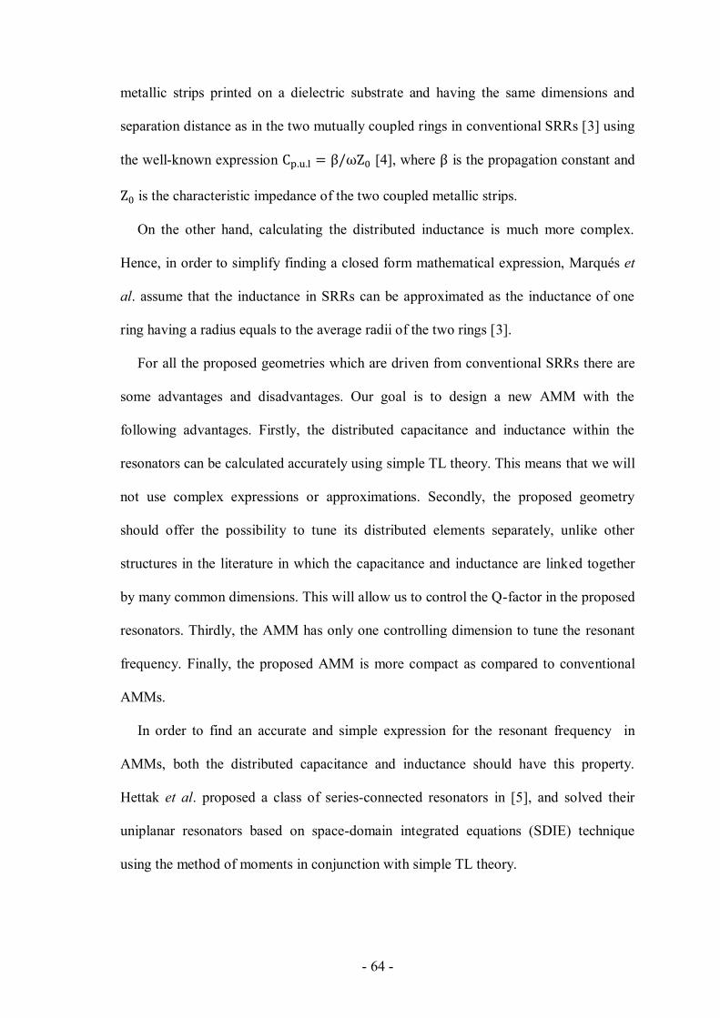
- 64 -
metallic strips printed on a dielectric substrate and having the same dimensions and
separation distance as in the two mutually coupled rings in conventional SRRs [3] using
the well-known expression [4], where is the propagation constant and
is the characteristic impedance of the two coupled metallic strips.
On the other hand, calculating the distributed inductance is much more complex.
Hence, in order to simplify finding a closed form mathematical expression, Marqués et
al. assume that the inductance in SRRs can be approximated as the inductance of one
ring having a radius equals to the average radii of the two rings [3].
For all the proposed geometries which are driven from conventional SRRs there are
some advantages and disadvantages. Our goal is to design a new AMM with the
following advantages. Firstly, the distributed capacitance and inductance within the
resonators can be calculated accurately using simple TL theory. This means that we will
not use complex expressions or approximations. Secondly, the proposed geometry
should offer the possibility to tune its distributed elements separately, unlike other
structures in the literature in which the capacitance and inductance are linked together
by many common dimensions. This will allow us to control the Q-factor in the proposed
resonators. Thirdly, the AMM has only one controlling dimension to tune the resonant
frequency. Finally, the proposed AMM is more compact as compared to conventional
AMMs.
In order to find an accurate and simple expression for the resonant frequency in
AMMs, both the distributed capacitance and inductance should have this property.
Hettak et al. proposed a class of series-connected resonators in [5], and solved their
uniplanar resonators based on space-domain integrated equations (SDIE) technique
using the method of moments in conjunction with simple TL theory.
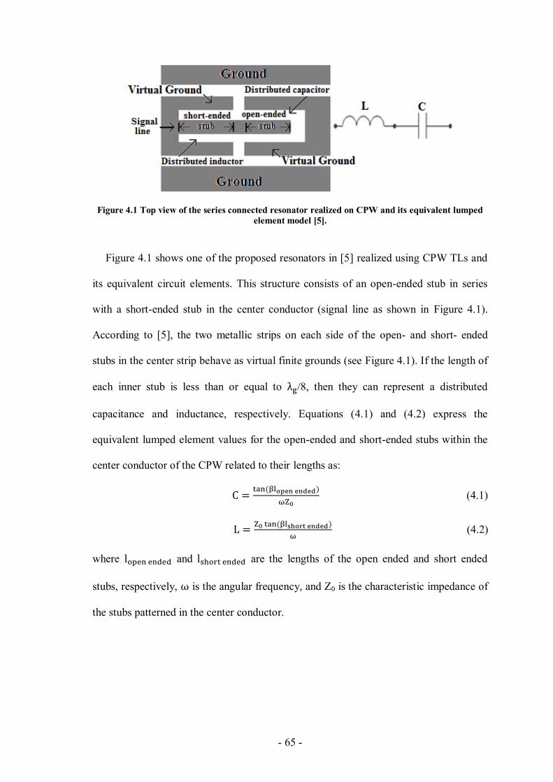
- 65 -
Figure 4.1 Top view of the series connected resonator realized on CPW and its equivalent lumped
element model [5].
Figure 4.1 shows one of the proposed resonators in [5] realized using CPW TLs and
its equivalent circuit elements. This structure consists of an open-ended stub in series
with a short-ended stub in the center conductor (signal line as shown in Figure 4.1).
According to [5], the two metallic strips on each side of the open- and short- ended
stubs in the center strip behave as virtual finite grounds (see Figure 4.1). If the length of
each inner stub is less than or equal to /8, then they can represent a distributed
capacitance and inductance, respectively. Equations (4.1) and (4.2) express the
equivalent lumped element values for the open-ended and short-ended stubs within the
center conductor of the CPW related to their lengths as:
(4.1)
(4.2)
where and are the lengths of the open ended and short ended
stubs, respectively, is the angular frequency, and Z0 is the characteristic impedance of
the stubs patterned in the center conductor.
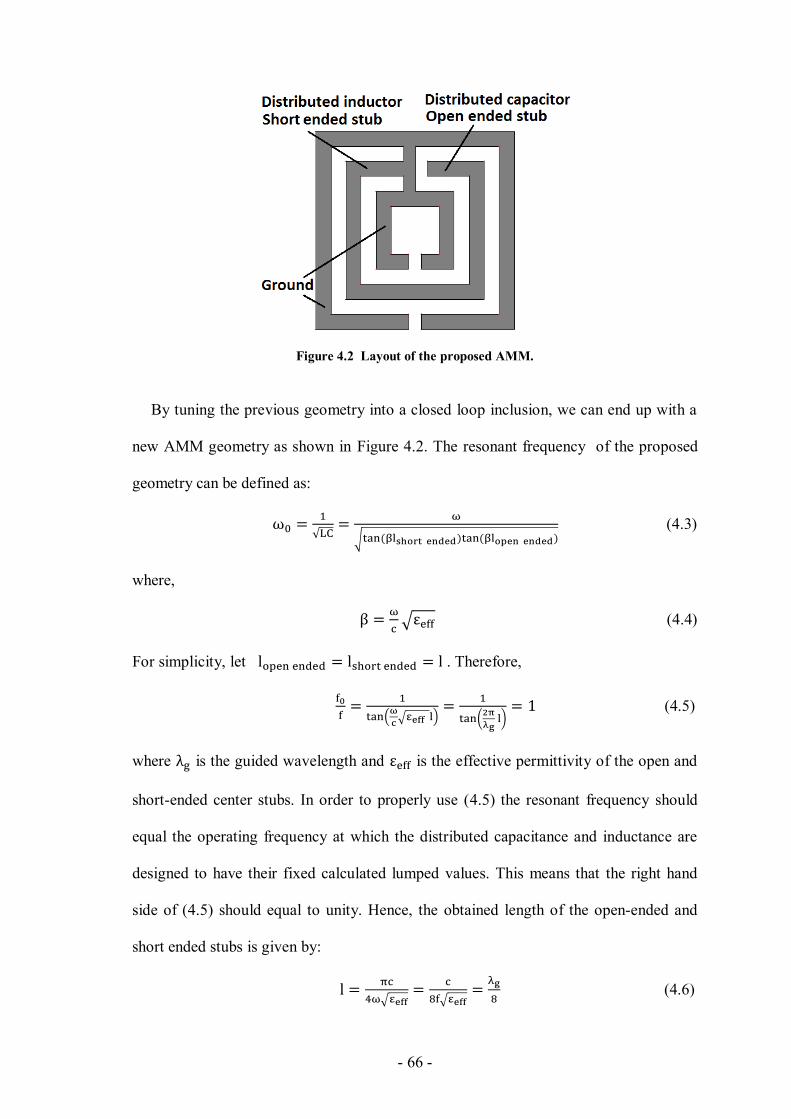
- 66 -
Figure 4.2 Layout of the proposed AMM.
By tuning the previous geometry into a closed loop inclusion, we can end up with a
new AMM geometry as shown in Figure 4.2. The resonant frequency of the proposed
geometry can be defined as:
(4.3)
where,
(4.4)
For simplicity, let . Therefore,
(4.5)
where is the guided wavelength and is the effective permittivity of the open and
short-ended center stubs. In order to properly use (4.5) the resonant frequency should
equal the operating frequency at which the distributed capacitance and inductance are
designed to have their fixed calculated lumped values. This means that the right hand
side of (4.5) should equal to unity. Hence, the obtained length of the open-ended and
short ended stubs is given by:
(4.6)

- 67 -
4.2 Advantages of the proposed design over conventional SRRs
The following can be concluded from the previous equations. Firstly, the resonant
frequency depends only on one dimension (i.e. the stubs' lengths), unlike SRR or other
AMMs derived from conventional SRRs.
Secondly, one can independently tune the values of the distributed passive elements
by changing the length of the inner stubs. This property gives an advantage over SRRs,
whose distributed capacitance and inductance are linked together by many common
geometrical dimensions. Hence, using the proposed AMM, the quality factors in AMM-
based microwave circuits can be simply controlled by independently changing the stubs'
length. This property can significantly enhance and control the passbands, stopbands,
and the fractional bandwidths in AMM-based filters.
Thirdly, the resonant frequency does not depend on the characteristic impedance of
the open and short-ended stubs. This property gives us more design flexibility in
choosing the width of the center stubs and the spacing between the finite grounds and
the stubs. Therefore, these dimensions can be decreased to provide additional
compactness, as long as they meet the fabrication limits.
Fourthly, the resonant frequency of the proposed AMM is lower than the resonant
frequency of a similar-size conventional square split resonator. Hence, a significant
reduction in the size of the proposed AMM is achieved as compared to a conventional
square SRR having the same resonant frequency .
Fifthly, since the proposed resonator depends on TL theory, it is possible to scale the
lengths of the center stubs (one dimensional scaling) in order to linearly shift the
resonant frequency .

- 68 -
Finally, the expression in (4.6) is simple, straightforward, and accurate, as long as the
lengths of the inner stubs equal to /8.
4.3 A design example (simulations, and measurements)
To demonstrate the performance of the proposed structure, a one-period square
resonator backed CPW has been designed and fabricated as shown in Figure 4.3. The
substrate used is RT/Duroid 6010LM which has a dielectric constant of 10.2, loss
tangent of 0.0023, and a thickness of 0.635 mm. The designed resonant frequency of
the proposed AMM is 3.4 GHz. Hence, using (4.6) the open- and short-ended stubs
within the resonators are 4.20 mm, given that eff =6.89, which is the same as eff for a
finite-ground CPW TL having the same dimensions as the inner stubs [6].
Figure 4.4 shows the simulated and measured scattering parameters of the proposed
metamaterial-based resonator. We used the full-wave electromagnetic simulator IE3D
which is based on the method of moments to design the AMM [7]. The simulated
resonant frequency appears at 3.35 GHz, which is very close to the theoretical value
(3.4 GHz). The small difference between the simulated and the theoretical values can be
attributed to the parasitic discontinuities in CPW TLs. However, these discontinuities
have a negligible effect on the performance of the AMM. A shift of 0.02 GHz in the
resonant frequency between the measured and simulated responses is observed as
shown in Figure 4.4. This shift maybe due to fabrication tolerance.
Table 4.1 summarizes the simulated and measured characteristics of the proposed
AMM. The 3-dB bandwidth and the Q-factor can be easily controlled since they are
directly linked to the tunable distributed capacitance and inductance within the AMM.
Besides its accurate estimated resonant frequency, the proposed AMM shows very good
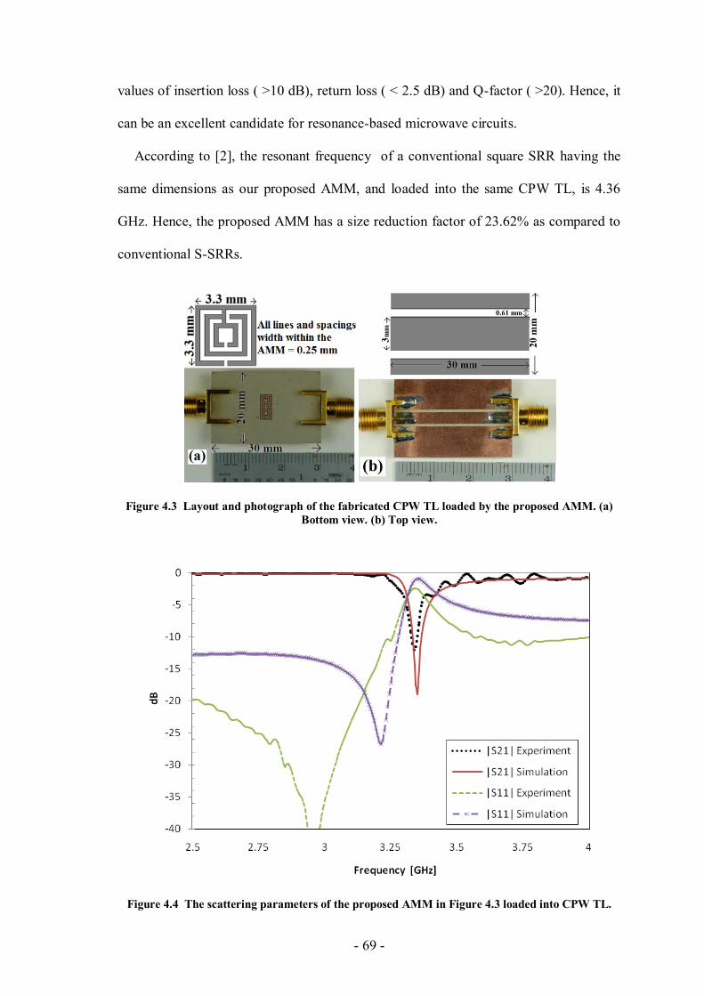
- 69 -
values of insertion loss ( >10 dB), return loss ( < 2.5 dB) and Q-factor ( >20). Hence, it
can be an excellent candidate for resonance-based microwave circuits.
According to [2], the resonant frequency of a conventional square SRR having the
same dimensions as our proposed AMM, and loaded into the same CPW TL, is 4.36
GHz. Hence, the proposed AMM has a size reduction factor of 23.62% as compared to
conventional S-SRRs.
Figure 4.3 Layout and photograph of the fabricated CPW TL loaded by the proposed AMM. (a)
Bottom view. (b) Top view.
Figure 4.4 The scattering parameters of the proposed AMM in Figure 4.3 loaded into CPW TL.
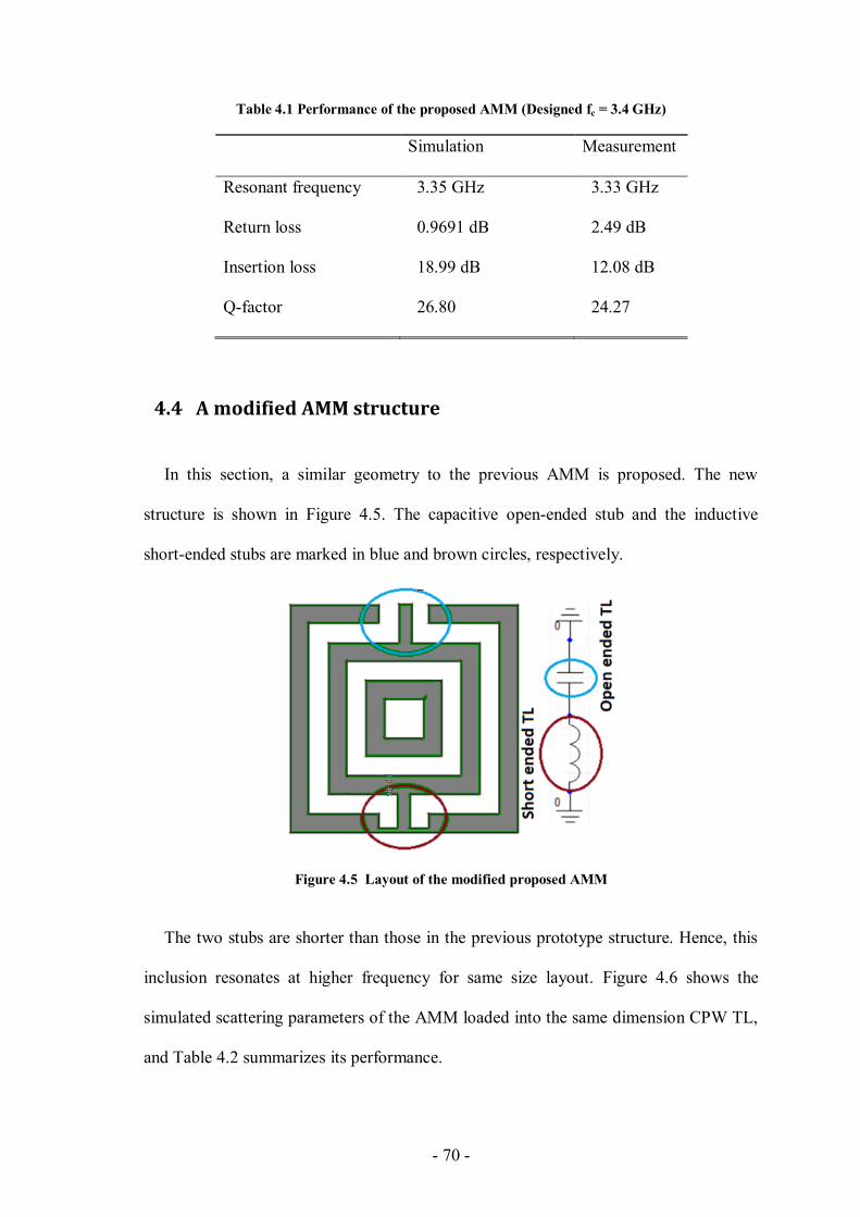
- 70 -
Table 4.1 Performance of the proposed AMM (Designed fc = 3.4 GHz)
Simulation Measurement
Resonant frequency 3.35 GHz 3.33 GHz
Return loss 0.9691 dB 2.49 dB
Insertion loss 18.99 dB 12.08 dB
Q-factor 26.80 24.27
4.4 A modified AMM structure
In this section, a similar geometry to the previous AMM is proposed. The new
structure is shown in Figure 4.5. The capacitive open-ended stub and the inductive
short-ended stubs are marked in blue and brown circles, respectively.
Figure 4.5 Layout of the modified proposed AMM
The two stubs are shorter than those in the previous prototype structure. Hence, this
inclusion resonates at higher frequency for same size layout. Figure 4.6 shows the
simulated scattering parameters of the AMM loaded into the same dimension CPW TL,
and Table 4.2 summarizes its performance.

- 71 -
Figure 4.6 The scattering parameters of the AMM loaded into CPW TL.
Table 4.2 Performance of the AMM shown in Figure 4.5
Simulation
Resonant frequency 5.26 GHz
Return loss 1.17 dB
Insertion loss 17.89 dB
Q-factor 26.31
4.5 Other metamaterial inclusions based on CPW discontinuities
This section introduces a new inclusion based on other coplanar waveguide (CPW)
discontinuities. Figure 4.7 (a) shows the layout of the inclusion. The structure can be
separated into two parts; a distributed capacitance across the gap on the center strip of
the CPW TL, and a distributed inductive high-impedance TL. The two passive
distributed elements are connected in series and bent into a closed-loop square shape in
order to permit the flow of the resonant currents.
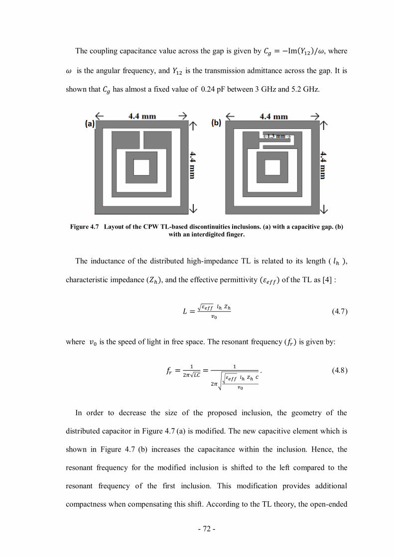
- 72 -
The coupling capacitance value across the gap is given by , where
is the angular frequency, and is the transmission admittance across the gap. It is
shown that has almost a fixed value of 0.24 pF between 3 GHz and 5.2 GHz.
Figure 4.7 Layout of the CPW TL-based discontinuities inclusions. (a) with a capacitive gap. (b)
with an interdigited finger.
The inductance of the distributed high-impedance TL is related to its length ( ,
characteristic impedance ( , and the effective permittivity of the TL as [4] :
where is the speed of light in free space. The resonant frequency ( is given by:
In order to decrease the size of the proposed inclusion, the geometry of the
distributed capacitor in Figure 4.7 (a) is modified. The new capacitive element which is
shown in Figure 4.7 (b) increases the capacitance within the inclusion. Hence, the
resonant frequency for the modified inclusion is shifted to the left compared to the
resonant frequency of the first inclusion. This modification provides additional
compactness when compensating this shift. According to the TL theory, the open-ended
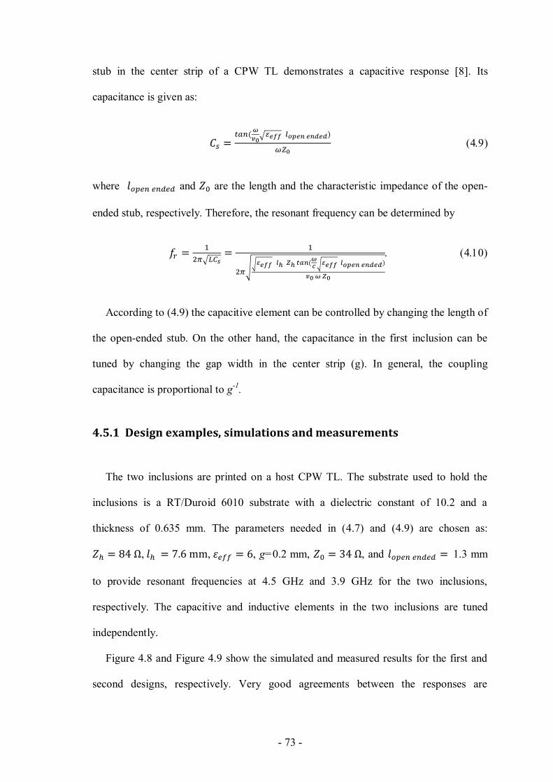
- 73 -
stub in the center strip of a CPW TL demonstrates a capacitive response [8]. Its
capacitance is given as:
where and are the length and the characteristic impedance of the open-
ended stub, respectively. Therefore, the resonant frequency can be determined by
According to (4.9) the capacitive element can be controlled by changing the length of
the open-ended stub. On the other hand, the capacitance in the first inclusion can be
tuned by changing the gap width in the center strip (g). In general, the coupling
capacitance is proportional to g-1
.
4.5.1 Design examples, simulations and measurements
The two inclusions are printed on a host CPW TL. The substrate used to hold the
inclusions is a RT/Duroid 6010 substrate with a dielectric constant of 10.2 and a
thickness of 0.635 mm. The parameters needed in (4.7) and (4.9) are chosen as:
, , , g=0.2 mm, , and 1.3 mm
to provide resonant frequencies at 4.5 GHz and 3.9 GHz for the two inclusions,
respectively. The capacitive and inductive elements in the two inclusions are tuned
independently.
Figure 4.8 and Figure 4.9 show the simulated and measured results for the first and
second designs, respectively. Very good agreements between the responses are
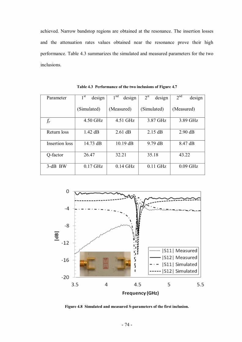
- 74 -
achieved. Narrow bandstop regions are obtained at the resonance. The insertion losses
and the attenuation rates values obtained near the resonance prove their high
performance. Table 4.3 summarizes the simulated and measured parameters for the two
inclusions.
Table 4.3 Performance of the two inclusions of Figure 4.7
Parameter 1st design
(Simulated)
1nd
design
(Measured)
2st design
(Simulated)
2nd
design
(Measured)
4.50 GHz 4.51 GHz 3.87 GHz 3.89 GHz
Return loss 1.42 dB 2.61 dB 2.15 dB 2.90 dB
Insertion loss 14.73 dB 10.19 dB 9.79 dB 8.47 dB
Q-factor 26.47 32.21 35.18 43.22
3-dB BW 0.17 GHz 0.14 GHz 0.11 GHz 0.09 GHz
Figure 4.8 Simulated and measured S-parameters of the first inclusion.

- 75 -
Figure 4.9 Simulated and measured S-parameters of the second inclusion.
4.6 Conclusion
In this chapter a new type of TL-based metamaterial resonators was introduced. The
distributed capacitors and inductors within the proposed resonators were controlled in a
simple and straightforward way. Hence, many advantages of the new designs over the
conventional implementation were achieved. In addition, two other CPW
discontinuities-based metamaterial inclusions were proposed. The inclusions contain
distributed capacitors and inductors connected along a folded coplanar waveguide
transmission line. Despite they share the same high-impedance inductive element; the
capacitive part was represented by a gap in the center strip in the first inclusion and an
open-ended stub in the center strip in the second inclusion. Numerical and experimental
results for all proposed inclusion were in excellent agreement. The demonstrated high
performance recommends the proposed structures as perfect candidates in the design of
resonant-based microwave circuits.
- 76 -
References
[1] J. B. Pendry, A. J. Holden, D. J. Ribbins, and W. J. Stewart, “Magnetism from
conductors and enhanced nonlinear phenomena,” IEEE Trans. Microwave Theory
Tech., vol. 47, pp. 2075–2084, Nov. 1999.
[2] C. Saha, J.Y. Siddiqui, and Y.M.M. Antar, “Square split ring resonator backed
coplanar waveguide for filter applications,” General Assembly and Scientific
Symposium, 2011 XXXth URSI , vol., no., pp.1-4, 13-20 Aug. 2011.
[3] R. Marqués, F. Mesa, J. Martel, and F. Medina, “Comparative analysis of edge- and
broadside-coupled split ring resonators for metamaterial design—Theory and
experiment,” IEEE Trans. Antennas Propag., vol. 51, no. 10, pp. 2572–2581, Oct.
2003.
[4] D. M. Pozar, Microwave Engineering. New York: Wiley, 2005.
[5] K. Hettak, N. Dib, A.-F.Sheta,and S.Toutain, “A class of Novel Uniplanar Series
Resonators and Their Implementation in Original Applications,” IEEE Trans.
Microwave Theory Tech., vol. 46, No. 9, pp.1270-1276, Sept.1998.
[6] R. N. Simons, Coplanar waveguide circuits, components, and systems, New York:
John Wiley & Sons, 2001.
[7] Zeland Software, Inc., “IE3D Simulator,” Fremont, CA, 1997.
[8] N. Dib, L. Katehi, G. Ponchak, and R. Simons, “Theoretical and experimental
characterization of coplanar waveguide discontinuities for filter applications,” IEEE
Trans. Microwave Theory Tech., vol. 39, pp. 873–882, May. 1991.

- 77 -
CHAPTER 5
5 Applications of the Proposed TL-Based
Inclusions
To examine the inherent capacity of the proposed TL-based inclusions, two design
examples that utilize the new inclusions are proposed in this chapter, a dual-band
bandstop filter and two hybrid branch line couplers. The inclusions provide a narrow
bandstop response in the first design, and a miniaturization effect in the second design.
Simulation results for the inclusions and the related applications show very good
agreement with measurements. The DBBSF shows a good bandpass response with
sharp attenuation near the passband. The HBLC with two resonators per branch had a
16.95% size reduction factor as compared to a conventional HBLC. These results
validate the utilization of the proposed resonators in realizing microwave circuits.
5.1 Dual-band bandstop filter example
In this section we present a new DBBS filter with a designed center band frequencies
at 1.6 GHz and 2.2 GHz, based on the technique developed in [1] in which a lumped
element model of four series-connected parallel LC resonators is derived from a
prototype Chebyshev low pass filter after two successive frequency transformations.
Abu Safia et al. used the same technique to implement their DBBSF using the
compact series-connected parallel LC resonators proposed in [2] to implement the four
resonators in [3]. In [4], Marqués et al. proposed a lumped element equivalent circuit
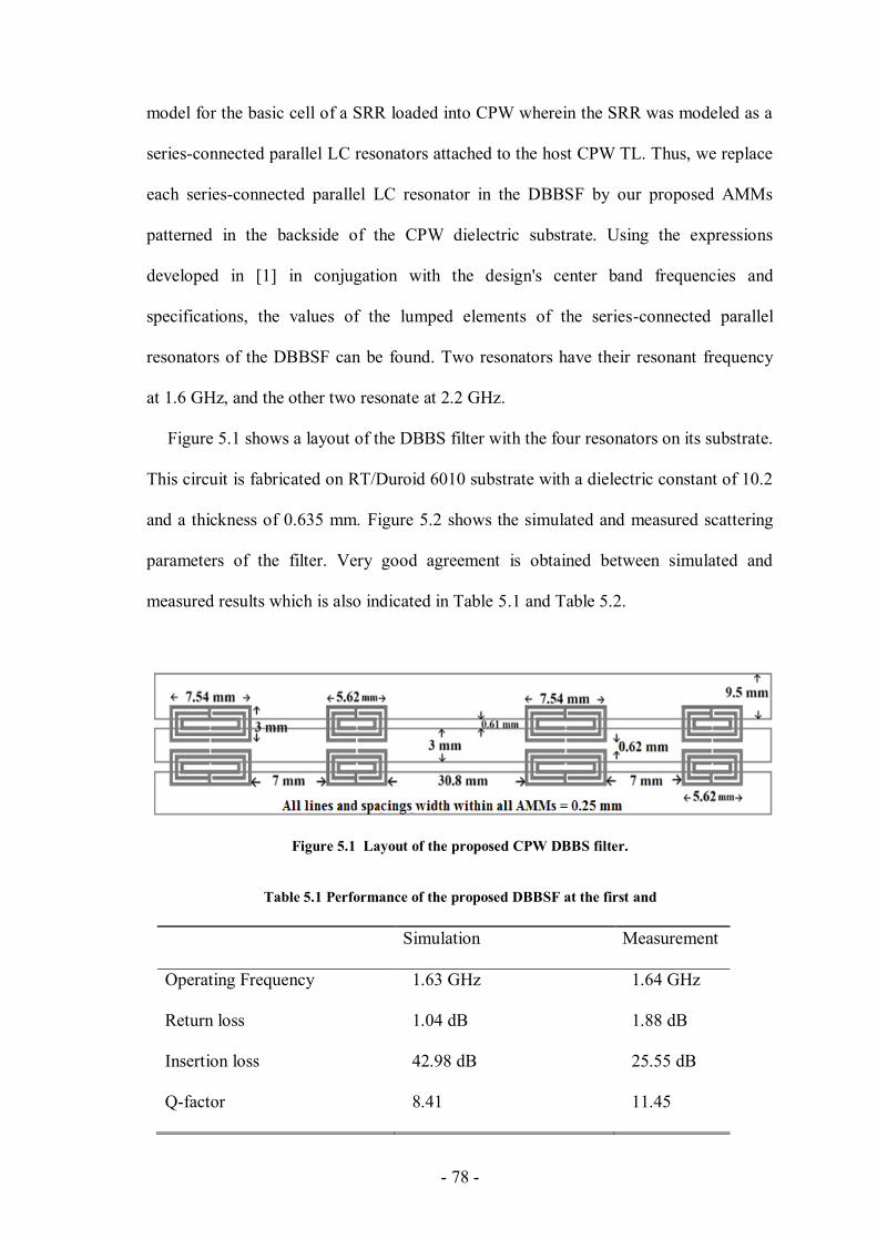
- 78 -
model for the basic cell of a SRR loaded into CPW wherein the SRR was modeled as a
series-connected parallel LC resonators attached to the host CPW TL. Thus, we replace
each series-connected parallel LC resonator in the DBBSF by our proposed AMMs
patterned in the backside of the CPW dielectric substrate. Using the expressions
developed in [1] in conjugation with the design's center band frequencies and
specifications, the values of the lumped elements of the series-connected parallel
resonators of the DBBSF can be found. Two resonators have their resonant frequency
at 1.6 GHz, and the other two resonate at 2.2 GHz.
Figure 5.1 shows a layout of the DBBS filter with the four resonators on its substrate.
This circuit is fabricated on RT/Duroid 6010 substrate with a dielectric constant of 10.2
and a thickness of 0.635 mm. Figure 5.2 shows the simulated and measured scattering
parameters of the filter. Very good agreement is obtained between simulated and
measured results which is also indicated in Table 5.1 and Table 5.2.
Figure 5.1 Layout of the proposed CPW DBBS filter.
Table 5.1 Performance of the proposed DBBSF at the first and
Simulation Measurement
Operating Frequency 1.63 GHz 1.64 GHz
Return loss 1.04 dB 1.88 dB
Insertion loss 42.98 dB 25.55 dB
Q-factor 8.41 11.45
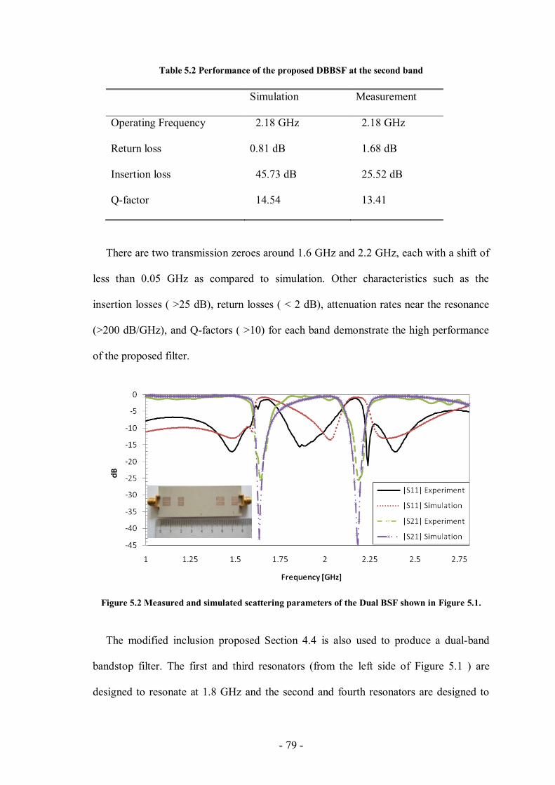
- 79 -
Table 5.2 Performance of the proposed DBBSF at the second band
Simulation Measurement
Operating Frequency 2.18 GHz 2.18 GHz
Return loss 0.81 dB 1.68 dB
Insertion loss 45.73 dB 25.52 dB
Q-factor 14.54 13.41
There are two transmission zeroes around 1.6 GHz and 2.2 GHz, each with a shift of
less than 0.05 GHz as compared to simulation. Other characteristics such as the
insertion losses ( >25 dB), return losses ( < 2 dB), attenuation rates near the resonance
(>200 dB/GHz), and Q-factors ( >10) for each band demonstrate the high performance
of the proposed filter.
Figure 5.2 Measured and simulated scattering parameters of the Dual BSF shown in Figure 5.1.
The modified inclusion proposed Section 4.4 is also used to produce a dual-band
bandstop filter. The first and third resonators (from the left side of Figure 5.1 ) are
designed to resonate at 1.8 GHz and the second and fourth resonators are designed to
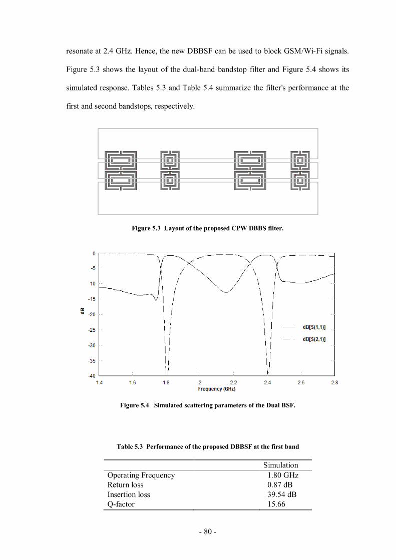
- 80 -
resonate at 2.4 GHz. Hence, the new DBBSF can be used to block GSM/Wi-Fi signals.
Figure 5.3 shows the layout of the dual-band bandstop filter and Figure 5.4 shows its
simulated response. Tables 5.3 and Table 5.4 summarize the filter's performance at the
first and second bandstops, respectively.
Figure 5.3 Layout of the proposed CPW DBBS filter.
Figure 5.4 Simulated scattering parameters of the Dual BSF.
Table 5.3 Performance of the proposed DBBSF at the first band
Simulation
Operating Frequency 1.80 GHz
Return loss 0.87 dB
Insertion loss 39.54 dB
Q-factor 15.66
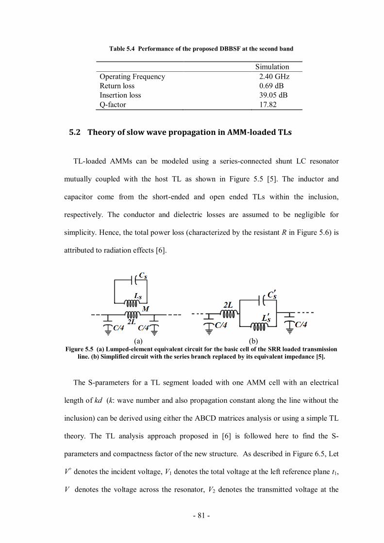
- 81 -
Table 5.4 Performance of the proposed DBBSF at the second band
Simulation
Operating Frequency 2.40 GHz
Return loss 0.69 dB
Insertion loss 39.05 dB
Q-factor 17.82
5.2 Theory of slow wave propagation in AMM-loaded TLs
TL-loaded AMMs can be modeled using a series-connected shunt LC resonator
mutually coupled with the host TL as shown in Figure 5.5 [5]. The inductor and
capacitor come from the short-ended and open ended TLs within the inclusion,
respectively. The conductor and dielectric losses are assumed to be negligible for
simplicity. Hence, the total power loss (characterized by the resistant R in Figure 5.6) is
attributed to radiation effects [6].
(a) (b) Figure 5.5 (a) Lumped-element equivalent circuit for the basic cell of the SRR loaded transmission
line. (b) Simplified circuit with the series branch replaced by its equivalent impedance [5].
The S-parameters for a TL segment loaded with one AMM cell with an electrical
length of kd (k: wave number and also propagation constant along the line without the
inclusion) can be derived using either the ABCD matrices analysis or using a simple TL
theory. The TL analysis approach proposed in [6] is followed here to find the S-
parameters and compactness factor of the new structure. As described in Figure 6.5, Let
V+ denotes the incident voltage, V1 denotes the total voltage at the left reference plane t1,
V denotes the voltage across the resonator, V2 denotes the transmitted voltage at the
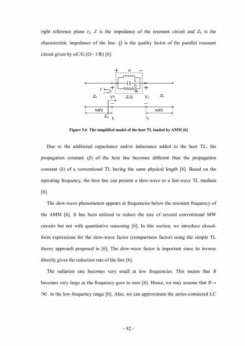
- 82 -
right reference plane t2, Z is the impedance of the resonant circuit and Z0 is the
characteristic impedance of the line. Q is the quality factor of the parallel resonant
circuit given by ωC/G (G= 1/R) [6].
Figure 5.6 The simplified model of the host TL loaded by AMM [6]
Due to the additional capacitance and/or inductance added to the host TL, the
propagation constant (β) of the host line becomes different than the propagation
constant (k) of a conventional TL having the same physical length [6]. Based on the
operating frequency, the host line can present a slow-wave or a fast-wave TL medium
[6].
The slow-wave phenomenon appears at frequencies below the resonant frequency of
the AMM [6]. It has been utilized to reduce the size of several conventional MW
circuits but not with quantitative reasoning [6]. In this section, we introduce closed-
form expressions for the slow-wave factor (compactness factor) using the simple TL
theory approach proposed in [6]. The slow-wave factor is important since its inverse
directly gives the reduction rate of the line [6].
The radiation rate becomes very small at low frequencies. This means that R
becomes very large as the frequency goes to zero [6]. Hence, we may assume that R→
in the low-frequency range [6]. Also, we can approximate the series-connected LC

- 83 -
resonator to be an inductor (we can neglect the capacitor in Figure 5.6 at low
frequencies) [6].
Using the expression of the reflection coefficient Г= jωL/(2Z0+ jωL) in Figure 5.6,
the voltage can be expressed as [6]:
(5.1)
and S21 is given by [6]:
(5.2)
at low-frequencies, the phase of can be approximated as [6]:
(5.3)
therefore, the electrical length of the loaded TL is given by [6]:
(5.4)
The dispersion factor for a transmission line loaded with the proposed inclusion
equals [6]:
=
(5.5)
The inductor, in the previous analysis, is considered a frequency-independent lumped
element. A more accurate model can be derived if the inductor considered as a
frequency-dependent distributed element. Figure 5.5 shows the inclusion mutually
coupled (inductive coupling) with the host line. The extra series-connected inductance
into the loaded line can be expressed as , where C is the capacitance of the
open-ended line within the inclusion [5]. M is the mutual coupling between the
inclusion and the line [5]. The value of the capacitance after considering the mutual
coupling with the host line is , where L is the inductance of the short-
ended line within the inclusion [5].
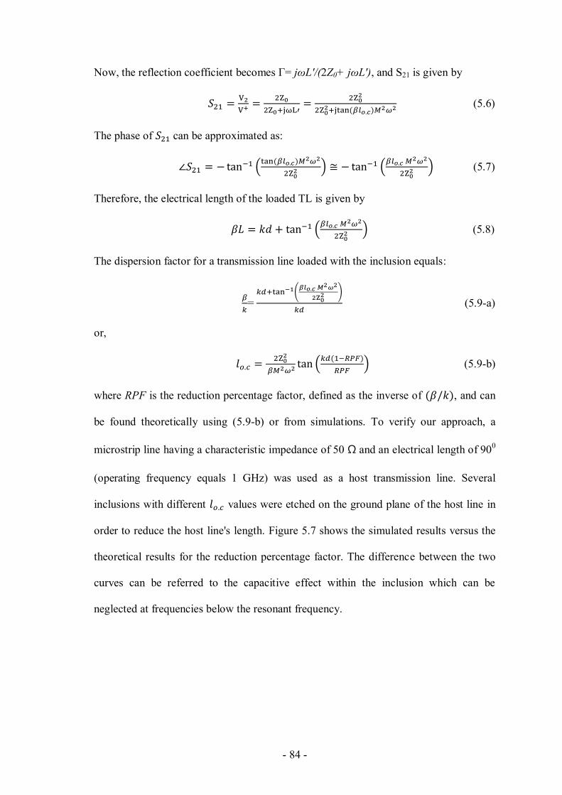
- 84 -
Now, the reflection coefficient becomes Г= jωL'/(2Z0+ jωL'), and S21 is given by
(5.6)
The phase of can be approximated as:
(5.7)
Therefore, the electrical length of the loaded TL is given by
(5.8)
The dispersion factor for a transmission line loaded with the inclusion equals:
=
(5.9-a)
or,
(5.9-b)
where RPF is the reduction percentage factor, defined as the inverse of , and can
be found theoretically using (5.9-b) or from simulations. To verify our approach, a
microstrip line having a characteristic impedance of 50 Ω and an electrical length of 900
(operating frequency equals 1 GHz) was used as a host transmission line. Several
inclusions with different values were etched on the ground plane of the host line in
order to reduce the host line's length. Figure 5.7 shows the simulated results versus the
theoretical results for the reduction percentage factor. The difference between the two
curves can be referred to the capacitive effect within the inclusion which can be
neglected at frequencies below the resonant frequency.

- 85 -
Figure 5.7 Reduction percentage factor in the length of a host microstrip line etched with different
values' inclusions. (f=1 GHz, Z0=50 Ω M=1.02×10⁻⁸
)
The second approach to extract the S-parameters is the ABCD matrices equivalence
of the line. The ABCD matrix of the inclusion can be expressed as:
, where Z=
. Considering only the inductance as explained before, the
ABCD matrix of the line is given by:
(5.10)
Therefore, the S-parameters of the line can be easily extracted. For example, S21 equals
S21 = 2/(A+B/Z0+CZ0+D) =
(5.11)
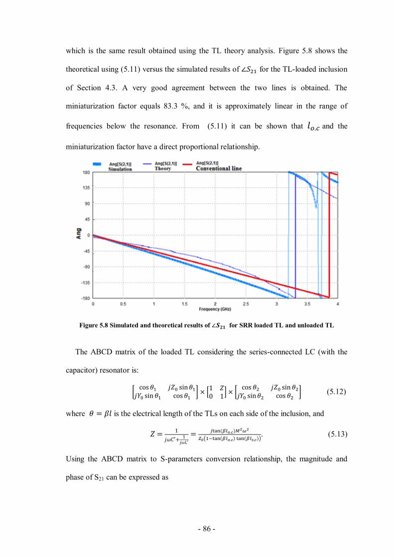
- 86 -
which is the same result obtained using the TL theory analysis. Figure 5.8 shows the
theoretical using (5.11) versus the simulated results of for the TL-loaded inclusion
of Section 4.3. A very good agreement between the two lines is obtained. The
miniaturization factor equals 83.3 %, and it is approximately linear in the range of
frequencies below the resonance. From (5.11) it can be shown that and the
miniaturization factor have a direct proportional relationship.
Figure 5.8 Simulated and theoretical results of for SRR loaded TL and unloaded TL
The ABCD matrix of the loaded TL considering the series-connected LC (with the
capacitor) resonator is:
(5.12)
where is the electrical length of the TLs on each side of the inclusion, and
. (5.13)
Using the ABCD matrix to S-parameters conversion relationship, the magnitude and
phase of S21 can be expressed as
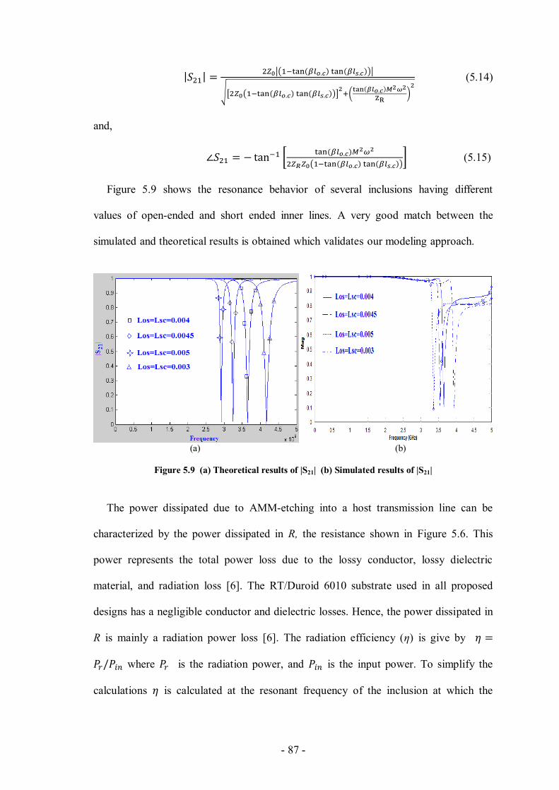
- 87 -
(5.14)
and,
(5.15)
Figure 5.9 shows the resonance behavior of several inclusions having different
values of open-ended and short ended inner lines. A very good match between the
simulated and theoretical results is obtained which validates our modeling approach.
(a) (b)
Figure 5.9 (a) Theoretical results of |S21| (b) Simulated results of |S21|
The power dissipated due to AMM-etching into a host transmission line can be
characterized by the power dissipated in R, the resistance shown in Figure 5.6. This
power represents the total power loss due to the lossy conductor, lossy dielectric
material, and radiation loss [6]. The RT/Duroid 6010 substrate used in all proposed
designs has a negligible conductor and dielectric losses. Hence, the power dissipated in
R is mainly a radiation power loss [6]. The radiation efficiency (η) is give by
where is the radiation power, and is the input power. To simplify the
calculations is calculated at the resonant frequency of the inclusion at which the
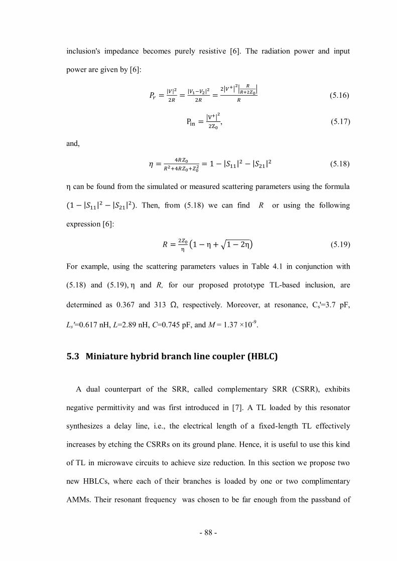
- 88 -
inclusion's impedance becomes purely resistive [6]. The radiation power and input
power are given by [6]:
(5.16)
, (5.17)
and,
(5.18)
can be found from the simulated or measured scattering parameters using the formula
. Then, from (5.18) we can find R or using the following
expression [6]:
(5.19)
For example, using the scattering parameters values in Table 4.1 in conjunction with
(5.18) and (5.19), and R, for our proposed prototype TL-based inclusion, are
determined as 0.367 and 313 Ω, respectively. Moreover, at resonance, Cs'=3.7 pF,
Ls'=0.617 nH, L=2.89 nH, C=0.745 pF, and M = 1.37 ×10⁻⁹
.
5.3 Miniature hybrid branch line coupler (HBLC)
A dual counterpart of the SRR, called complementary SRR (CSRR), exhibits
negative permittivity and was first introduced in [7]. A TL loaded by this resonator
synthesizes a delay line, i.e., the electrical length of a fixed-length TL effectively
increases by etching the CSRRs on its ground plane. Hence, it is useful to use this kind
of TL in microwave circuits to achieve size reduction. In this section we propose two
new HBLCs, where each of their branches is loaded by one or two complimentary
AMMs. Their resonant frequency was chosen to be far enough from the passband of
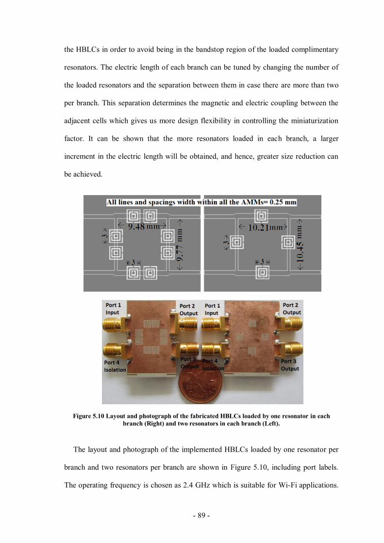
- 89 -
the HBLCs in order to avoid being in the bandstop region of the loaded complimentary
resonators. The electric length of each branch can be tuned by changing the number of
the loaded resonators and the separation between them in case there are more than two
per branch. This separation determines the magnetic and electric coupling between the
adjacent cells which gives us more design flexibility in controlling the miniaturization
factor. It can be shown that the more resonators loaded in each branch, a larger
increment in the electric length will be obtained, and hence, greater size reduction can
be achieved.
Figure 5.10 Layout and photograph of the fabricated HBLCs loaded by one resonator in each
branch (Right) and two resonators in each branch (Left).
The layout and photograph of the implemented HBLCs loaded by one resonator per
branch and two resonators per branch are shown in Figure 5.10, including port labels.
The operating frequency is chosen as 2.4 GHz which is suitable for Wi-Fi applications.
- 90 -
Both circuits are fabricated on RT/Duroid 6010 substrates with a dielectric constant of
10.2 and a thickness of 0.635 mm. For both circuits the measured scattering parameters
are shown in Figure 5.11, and their measured performances parameters are summarized
in Table 5.5. In the two circuits, the phase differences between S21 and S31 are close to
900 at 2.4 GHz with, with quadrature phase difference errors less than 1
0. The amplitude
imbalance between S21 and S31 is less than 0.2 dB in both circuits, which means that the
incident power is evenly divided between ports 2 and 3 with insertion losses less than
3.7 dB. The isolation/return losses are larger than 15 dB in the two circuits, and the size
reduction factors for the new HBLCs compared to the conventional HBLC for one and
two resonators loaded per branch are 10.58% and 16.95%, respectively. Hence, this
loading technique minimizes the size of HBLCs without affecting their high
performance.
Table 5.5 Performance of the HBLCs (Measured Response)
Loading per branch One resonator Two resonators
Operating Frequency 2.41 GHz 2.39 GHz
Return loss 15.25 dB 19.54 dB
Isolation 16.61 dB 17.33 dB
Output 1 -3.65 dB -3.44 dB
Output 2 -3.50 dB -3.27 dB
Amplitude Imbalance 0.15 dB 0.17 dB
Outputs phase Difference 0.08 0.04
Miniaturization factor 10.58 % 16.95%

- 91 -
Figure 5.11 Measured responses for the proposed HBLCs shown in Figure 5.10. (a) Measured S-
parameters of the HBLC loaded by one resonator per branch. (b) Measured S-parameters of the
HBLC loaded by two resonators per branch. (c) Measured output phase differences in the loaded
HBLCs as compared to a conventional HBLC.

- 92 -
Now, the complimantay shape of the modified inclusion proposed in Section 4.4 is
loaded in the ground plane of two HBLCs. Figure 5.12 shows the layout of the ground
plane of the two compact HBLCs. The first coupler is loaded by two resonator per
branch and the second one is loaded by one resonators per branch.
Figure 5.12 Layout of the ground planes of the proposed HBLCs loaded by (a) two resonators in
each branch and (b) one resonator in each branch.
The simulated responses of the two couplers are shown in Figure 5.13, and their
performance parameters are shown it Table 5.6.
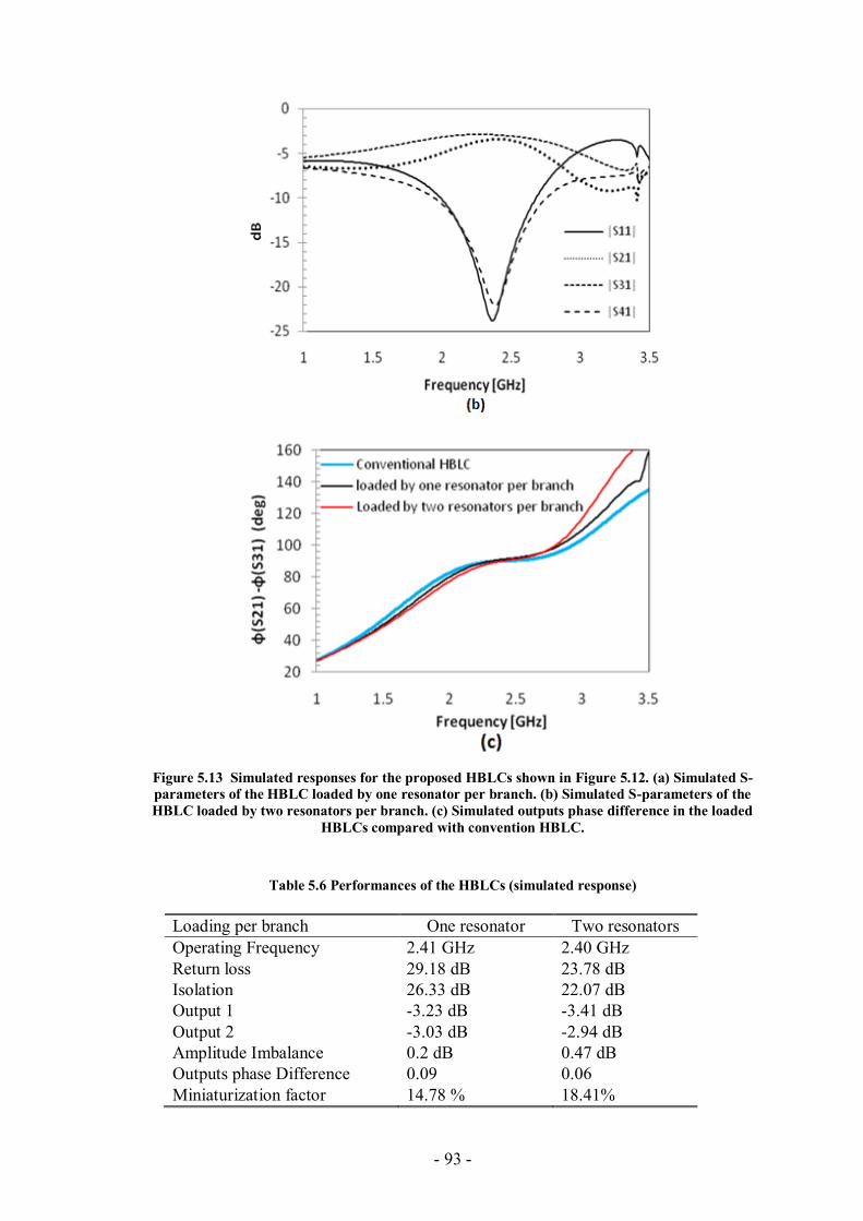
- 93 -
Figure 5.13 Simulated responses for the proposed HBLCs shown in Figure 5.12. (a) Simulated S-
parameters of the HBLC loaded by one resonator per branch. (b) Simulated S-parameters of the
HBLC loaded by two resonators per branch. (c) Simulated outputs phase difference in the loaded
HBLCs compared with convention HBLC.
Table 5.6 Performances of the HBLCs (simulated response)
Loading per branch One resonator Two resonators
Operating Frequency 2.41 GHz 2.40 GHz
Return loss 29.18 dB 23.78 dB
Isolation 26.33 dB 22.07 dB
Output 1 -3.23 dB -3.41 dB
Output 2 -3.03 dB -2.94 dB
Amplitude Imbalance 0.2 dB 0.47 dB
Outputs phase Difference 0.09 0.06
Miniaturization factor 14.78 % 18.41%
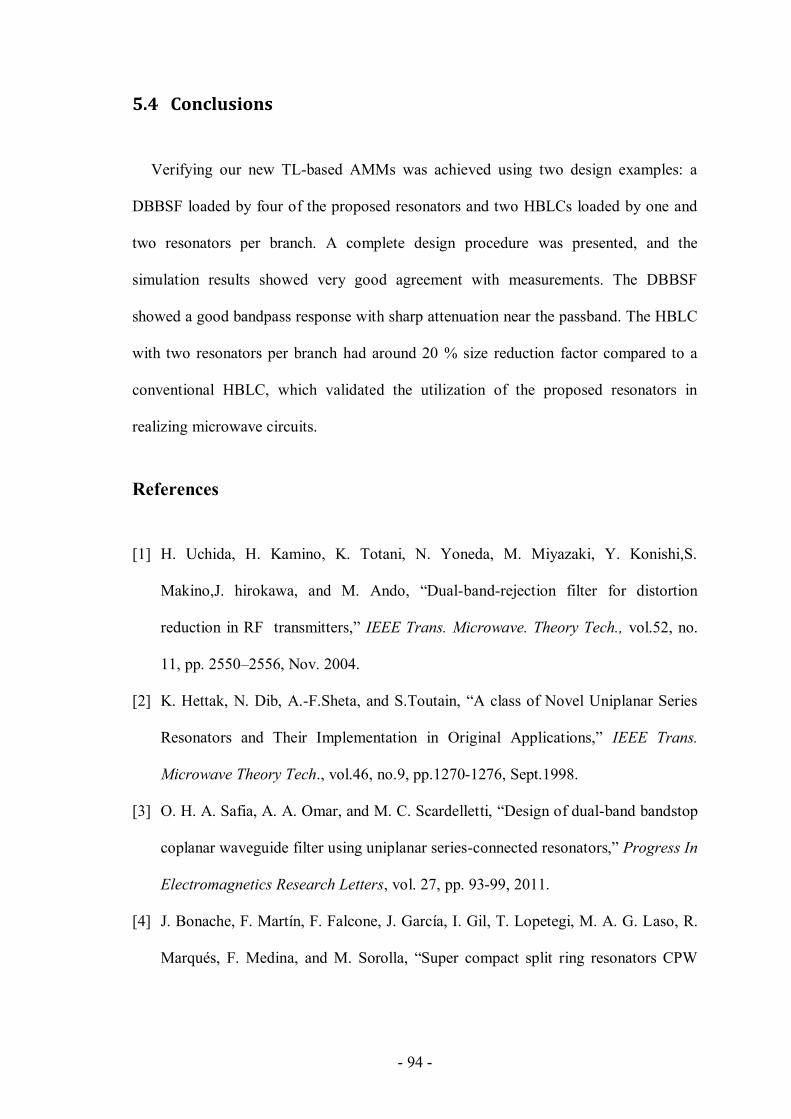
- 94 -
5.4 Conclusions
Verifying our new TL-based AMMs was achieved using two design examples: a
DBBSF loaded by four of the proposed resonators and two HBLCs loaded by one and
two resonators per branch. A complete design procedure was presented, and the
simulation results showed very good agreement with measurements. The DBBSF
showed a good bandpass response with sharp attenuation near the passband. The HBLC
with two resonators per branch had around 20 % size reduction factor compared to a
conventional HBLC, which validated the utilization of the proposed resonators in
realizing microwave circuits.
References
[1] H. Uchida, H. Kamino, K. Totani, N. Yoneda, M. Miyazaki, Y. Konishi,S.
Makino,J. hirokawa, and M. Ando, “Dual-band-rejection filter for distortion
reduction in RF transmitters,” IEEE Trans. Microwave. Theory Tech., vol.52, no.
11, pp. 2550–2556, Nov. 2004.
[2] K. Hettak, N. Dib, A.-F.Sheta, and S.Toutain, “A class of Novel Uniplanar Series
Resonators and Their Implementation in Original Applications,” IEEE Trans.
Microwave Theory Tech., vol.46, no.9, pp.1270-1276, Sept.1998.
[3] O. H. A. Safia, A. A. Omar, and M. C. Scardelletti, “Design of dual-band bandstop
coplanar waveguide filter using uniplanar series-connected resonators,” Progress In
Electromagnetics Research Letters, vol. 27, pp. 93-99, 2011.
[4] J. Bonache, F. Martín, F. Falcone, J. García, I. Gil, T. Lopetegi, M. A. G. Laso, R.
Marqués, F. Medina, and M. Sorolla, “Super compact split ring resonators CPW
- 95 -
bandpass filters,” in IEEE-MTT Int. Microw. Symp. Dig., Fort Worth, TX, Jun.
2004, pp. 1483–1486.
[5] Baena, J.D.; Bonache, J.; Martin, F.; Sillero, R.M.; Falcone, F.; Lopetegi, T.; Laso,
M.A.G.; Garcia-Garcia, J.; Gil, I.; Portillo, M.F.; Sorolla, M.; , "Equivalent-circuit
models for split-ring resonators and complementary split-ring resonators coupled to
planar transmission lines," Microwave Theory and Techniques, IEEE Transactions
on , vol.53, no.4, pp. 1451- 1461, April 2005.
[6] Hyung-Mi Kim; Lee, B., "Bandgap and slow/fast-wave characteristics of defected
ground structures (DGSs) including left-handed features," Microwave Theory and
Techniques, IEEE Transactions on , vol.54, no.7, pp.3113,3120, July 2006.
[7] F. Falcone, T. Lopetegi, J. D. Baena, R. Marqués, F. Martín, and M.Sorolla,
“Effective negative-ε stopband microstrip lines based on complementary split ring
resonators,” IEEE Microw.Wireless Compon. Lett., vol. 14, no. 6, pp. 280–282, Jun.
2004.

- 96 -
- 97 -
CHAPTER 6
6 Dual-Resonant Metamaterial Inclusion Using
Composite Right/left-handed Transmission Line
Elements
This chapter introduces a dual-resonant inclusion based on a geometrical
modification of the TL-based inclusion proposed in Section 4.3. Because of the TL-
based property of that inclusion, it is possible to replace its conventional open-ended
and short-ended lines with CRLH TLs in order to have the dual-resonant-response
inclusion. The new inclusion can be used as a simple dual-band bandstop filter and
deployed into several antenna designs as shown later in this chapter.
This chapter is organized as follows: Section 6.1 discusses thoroughly the harmonic
resonant behavior of the prototype TL-based inclusion used to attain our proposed dual-
resonant inclusion. In Section 6.2, we introduce the idea of using CRLH TL-based
distributed elements in order to have a dual-resonant inclusion. A design procedure for
the proposed inclusion is introduced in Section 6.3. In Section 6.4, a design example of
the proposed inclusion having resonant frequencies at 3.5 GHz and 5.5 GHz is
introduced. Simulated and measured results are also shown and discussed in this
section. In Section 6.5, the inclusion is utilized to produce two antenna designs: a dual-
band CPW-fed single folded slot antenna and an UWB dual-notched antenna. As will be
seen, a very good performance for each proposed structure is obtained.
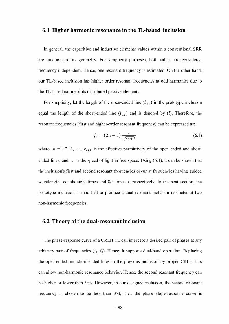
- 98 -
6.1 Higher harmonic resonance in the TL-based inclusion
In general, the capacitive and inductive elements values within a conventional SRR
are functions of its geometry. For simplicity purposes, both values are considered
frequency independent. Hence, one resonant frequency is estimated. On the other hand,
our TL-based inclusion has higher order resonant frequencies at odd harmonics due to
the TL-based nature of its distributed passive elements.
For simplicity, let the length of the open-ended line ( in the prototype inclusion
equal the length of the short-ended line ( and is denoted by ( ). Therefore, the
resonant frequencies (first and higher-order resonant frequency) can be expressed as:
(6.1)
where =1, 2, 3, …., is the effective permittivity of the open-ended and short-
ended lines, and is the speed of light in free space. Using (6.1), it can be shown that
the inclusion's first and second resonant frequencies occur at frequencies having guided
wavelengths equals eight times and 8/3 times , respectively. In the next section, the
prototype inclusion is modified to produce a dual-resonant inclusion resonates at two
non-harmonic frequencies.
6.2 Theory of the dual-resonant inclusion
The phase-response curve of a CRLH TL can intercept a desired pair of phases at any
arbitrary pair of frequencies (f1, f2). Hence, it supports dual-band operation. Replacing
the open-ended and short ended lines in the previous inclusion by proper CRLH TLs
can allow non-harmonic resonance behavior. Hence, the second resonant frequency can
be higher or lower than 3×fr. However, in our designed inclusion, the second resonant
frequency is chosen to be less than 3×fr. i.e., the phase slope-response curve is
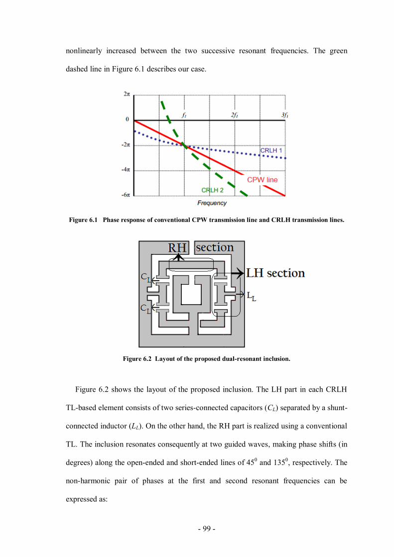
- 99 -
nonlinearly increased between the two successive resonant frequencies. The green
dashed line in Figure 6.1 describes our case.
Figure 6.1 Phase response of conventional CPW transmission line and CRLH transmission lines.
Figure 6.2 Layout of the proposed dual-resonant inclusion.
Figure 6.2 shows the layout of the proposed inclusion. The LH part in each CRLH
TL-based element consists of two series-connected capacitors (CL) separated by a shunt-
connected inductor (LL). On the other hand, the RH part is realized using a conventional
TL. The inclusion resonates consequently at two guided waves, making phase shifts (in
degrees) along the open-ended and short-ended lines of 450 and 135
0, respectively. The
non-harmonic pair of phases at the first and second resonant frequencies can be
expressed as:
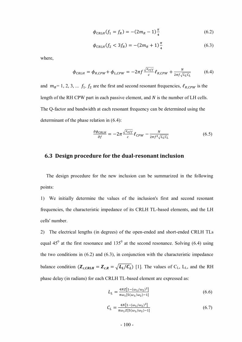
- 100 -
(6.2)
(6.3)
where,
(6.4)
and = 1, 2, 3, ... , are the first and second resonant frequencies, is the
length of the RH CPW part in each passive element, and is the number of LH cells.
The Q-factor and bandwidth at each resonant frequency can be determined using the
determinant of the phase relation in (6.4):
(6.5)
6.3 Design procedure for the dual-resonant inclusion
The design procedure for the new inclusion can be summarized in the following
points:
1) We initially determine the values of the inclusion's first and second resonant
frequencies, the characteristic impedance of its CRLH TL-based elements, and the LH
cells' number.
2) The electrical lengths (in degrees) of the open-ended and short-ended CRLH TLs
equal 450 at the first resonance and 135
0 at the second resonance. Solving (6.4) using
the two conditions in (6.2) and (6.3), in conjunction with the characteristic impedance
balance condition [1]. The values of CL, LL, and the RH
phase delay (in radians) for each CRLH TL-based element are expressed as:
(6.6)
(6.7)
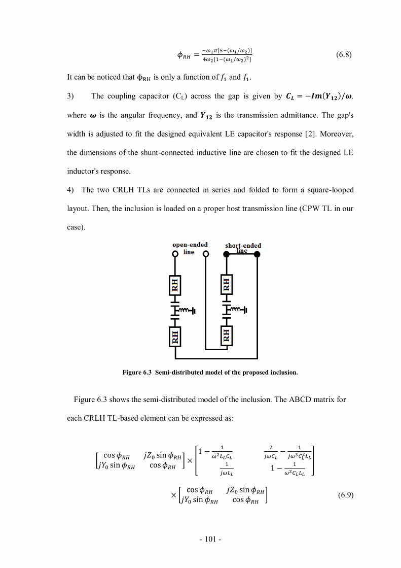
- 101 -
(6.8)
It can be noticed that is only a function of and .
3) The coupling capacitor (CL) across the gap is given by ,
where is the angular frequency, and is the transmission admittance. The gap's
width is adjusted to fit the designed equivalent LE capacitor's response [2]. Moreover,
the dimensions of the shunt-connected inductive line are chosen to fit the designed LE
inductor's response.
4) The two CRLH TLs are connected in series and folded to form a square-looped
layout. Then, the inclusion is loaded on a proper host transmission line (CPW TL in our
case).
Figure 6.3 Semi-distributed model of the proposed inclusion.
Figure 6.3 shows the semi-distributed model of the inclusion. The ABCD matrix for
each CRLH TL-based element can be expressed as:
(6.9)
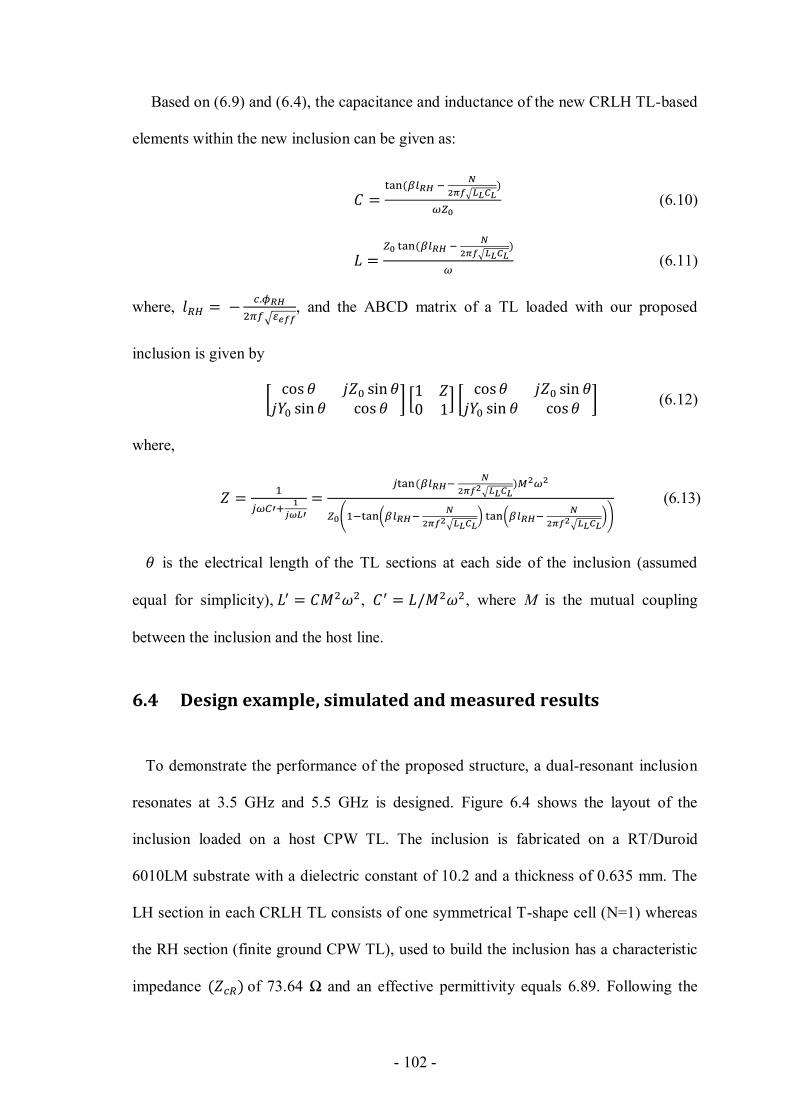
- 102 -
Based on (6.9) and (6.4), the capacitance and inductance of the new CRLH TL-based
elements within the new inclusion can be given as:
(6.10)
(6.11)
where,
, and the ABCD matrix of a TL loaded with our proposed
inclusion is given by
(6.12)
where,
(6.13)
is the electrical length of the TL sections at each side of the inclusion (assumed
equal for simplicity), , , where M is the mutual coupling
between the inclusion and the host line.
6.4 Design example, simulated and measured results
To demonstrate the performance of the proposed structure, a dual-resonant inclusion
resonates at 3.5 GHz and 5.5 GHz is designed. Figure 6.4 shows the layout of the
inclusion loaded on a host CPW TL. The inclusion is fabricated on a RT/Duroid
6010LM substrate with a dielectric constant of 10.2 and a thickness of 0.635 mm. The
LH section in each CRLH TL consists of one symmetrical T-shape cell (N=1) whereas
the RH section (finite ground CPW TL), used to build the inclusion has a characteristic
impedance of 73.64 Ω and an effective permittivity equals 6.89. Following the

- 103 -
aforementioned design procedure, the values of CL and LL equal 1.02 pF and 2.8 nH,
respectively. equals 113.70 From and , the design parameters of the RH
CPW TL section can be straightforwardly obtained [3].
Figure 6.4 Layout of the dual-band design example inclusion (resonates at 3.5GHz and 5.5 GHz)
loaded on a host CPW TL (a) Bottom view. (b) Top view.
Figure 6.5 shows the simulated and the measured scattering parameters of the
inclusion, and Table 6.1 shows its performance parameters.
Figure 6.5 Simulated and measured responses of the dual-band SRR loaded into a CPW TL.
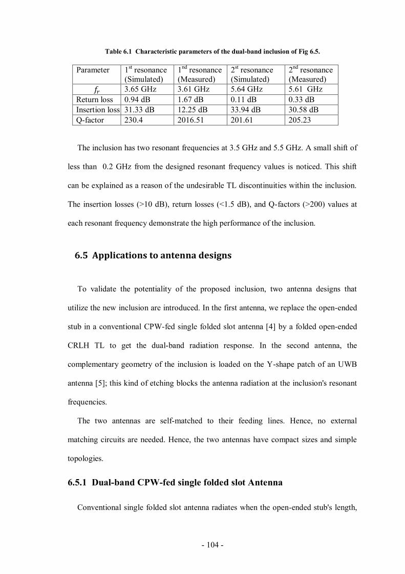
- 104 -
Table 6.1 Characteristic parameters of the dual-band inclusion of Fig 6.5.
Parameter 1st resonance
(Simulated)
1nd
resonance
(Measured)
2st resonance
(Simulated)
2nd
resonance
(Measured)
3.65 GHz 3.61 GHz 5.64 GHz 5.61 GHz
Return loss 0.94 dB 1.67 dB 0.11 dB 0.33 dB
Insertion loss 31.33 dB 12.25 dB 33.94 dB 30.58 dB
Q-factor 230.4 2016.51 201.61 205.23
The inclusion has two resonant frequencies at 3.5 GHz and 5.5 GHz. A small shift of
less than 0.2 GHz from the designed resonant frequency values is noticed. This shift
can be explained as a reason of the undesirable TL discontinuities within the inclusion.
The insertion losses (>10 dB), return losses (<1.5 dB), and Q-factors (>200) values at
each resonant frequency demonstrate the high performance of the inclusion.
6.5 Applications to antenna designs
To validate the potentiality of the proposed inclusion, two antenna designs that
utilize the new inclusion are introduced. In the first antenna, we replace the open-ended
stub in a conventional CPW-fed single folded slot antenna [4] by a folded open-ended
CRLH TL to get the dual-band radiation response. In the second antenna, the
complementary geometry of the inclusion is loaded on the Y-shape patch of an UWB
antenna [5]; this kind of etching blocks the antenna radiation at the inclusion's resonant
frequencies.
The two antennas are self-matched to their feeding lines. Hence, no external
matching circuits are needed. Hence, the two antennas have compact sizes and simple
topologies.
6.5.1 Dual-band CPW-fed single folded slot Antenna
Conventional single folded slot antenna radiates when the open-ended stub's length,
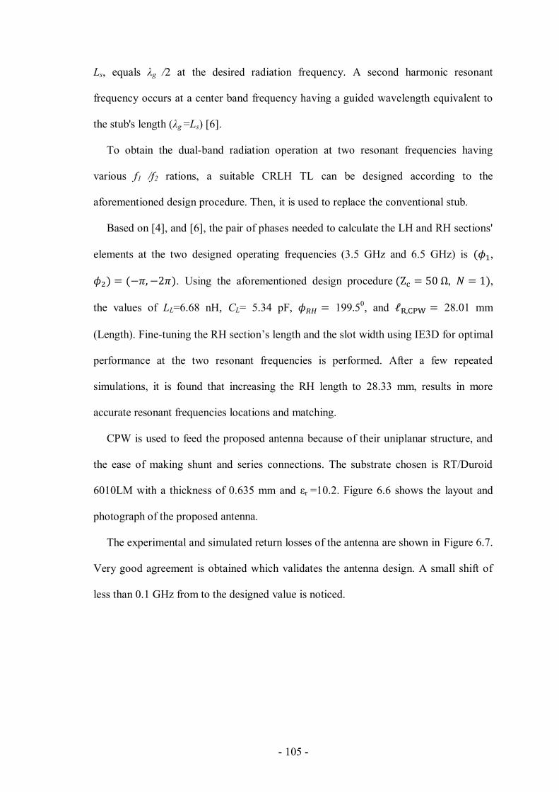
- 105 -
Ls, equals λg /2 at the desired radiation frequency. A second harmonic resonant
frequency occurs at a center band frequency having a guided wavelength equivalent to
the stub's length (λg =Ls) [6].
To obtain the dual-band radiation operation at two resonant frequencies having
various f1 /f2 rations, a suitable CRLH TL can be designed according to the
aforementioned design procedure. Then, it is used to replace the conventional stub.
Based on [4], and [6], the pair of phases needed to calculate the LH and RH sections'
elements at the two designed operating frequencies (3.5 GHz and 6.5 GHz) is ,
. Using the aforementioned design procedure , ,
the values of LL=6.68 nH, CL= 5.34 pF, 199.50, and 28.01 mm
(Length). Fine-tuning the RH section’s length and the slot width using IE3D for optimal
performance at the two resonant frequencies is performed. After a few repeated
simulations, it is found that increasing the RH length to 28.33 mm, results in more
accurate resonant frequencies locations and matching.
CPW is used to feed the proposed antenna because of their uniplanar structure, and
the ease of making shunt and series connections. The substrate chosen is RT/Duroid
6010LM with a thickness of 0.635 mm and εr =10.2. Figure 6.6 shows the layout and
photograph of the proposed antenna.
The experimental and simulated return losses of the antenna are shown in Figure 6.7.
Very good agreement is obtained which validates the antenna design. A small shift of
less than 0.1 GHz from to the designed value is noticed.

- 106 -
Figure 6.6 Layout and photograph of the dual-band antenna (resonates at 3.5 GHz and 6.5 GHz)
loaded on a host CPW TL (all dimensions in mm)
Figure 6.7 Measured and simulated return loss of the proposed antenna

- 107 -
Figure 6.8 Radiation pattern of the dual-band antenna of Figure 6.6 at 3.5 GHz.
Figure 6.9 Radiation pattern of the dual-band antenna of Figure 6.6 at 6.5 GHz.

- 108 -
The co-polarization and cross-polarization gain patterns of the antenna in the E-plane
(x-z plane) and H-plane (y-z plane) are shown in Figure 6.8 and Figure 6.9 for the two
center frequencies of 3.5 and 6.5 GHz, respectively. The antenna was measured in the
far-field range located in the Microwave Metrology Facility at Poly-Grames Research
Center, Montreal, QC. These patterns show that the antenna possesses a linear
polarization with cross polarization level more than 20 dBi lower than the co-
polarization level. At 3.50 and 6.5 GHz, the antenna gain is about 4.3 dBi.
6.5.2 Dual-notched UWB antenna
Slot-type SRR loading technique has been deployed into UWB antennas in order to
prevent the interference problem with other wireless systems in their vicinity [7]. In this
section, the complementary geometry of the proposed inclusion is etched on the Y-
shape patch of the UWB antenna proposed in [27]. This inclusion is designed to prevent
interference at certain center band frequencies. Besides its Y-shape patch, the antenna
has a trapezoidal ground plan printed on the back side of a 1.6 mm thick FR4 substrate
having a relative permittivity of 4.5 [8]. The band-notched property of the antenna is
achieved by guiding the currents at the notch frequencies concentrated in the dual-band
inclusion [27]. The layout and photograph of the fabricated antenna is shown in Figure
6.10.
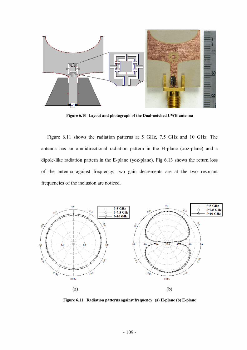
- 109 -
Figure 6.10 Layout and photograph of the Dual-notched UWB antenna
Figure 6.11 shows the radiation patterns at 5 GHz, 7.5 GHz and 10 GHz. The
antenna has an omnidirectional radiation pattern in the H-plane (xoz-plane) and a
dipole-like radiation pattern in the E-plane (yoz-plane). Fig 6.13 shows the return loss
of the antenna against frequency, two gain decrements are at the two resonant
frequencies of the inclusion are noticed.
(a) (b)
Figure 6.11 Radiation patterns against frequency: (a) H-plane (b) E-plane

- 110 -
Figure 6.12 Measured and simulated return loss of the proposed antenna
Figure 6.12 shows simulated and measured return loss versus frequency for the
antenna. The antenna provides a wide impedance bandwidth along the ultra-wideband
range with dual notched bands at 6 GHz and 9 GHz.
6.6 Conclusion
In this chapter, a dual-resonant metamaterial inclusion having composite right/left-
handed transmission line-based elements was proposed. The inclusion’s design was
based on a new hybrid technique which combined the two main metamaterial design
approaches, the resonance-type (split ring resonators) and the composite right/left-
handed transmission lines approaches, resulting in a dual-resonant response. The
geometry of the inclusion was derived from the TL-based prototype inclusion,
previously proposed in Section 4.1. The two resonant frequencies of the new inclusion
- 111 -
were controlled separately, using a proper combination of the right-handed and left-
handed sections for each passive element. The new technique and design procedure for
the inclusion were well established. To verify our proposed structure, it had been
deployed in two antenna designs. Firstly, a dual-band CPW-fed single folded slot
antenna which radiates at 3.5 GHz and 6.5 GHz. The antenna utilized the dual-band
property in CRLH TLs in order to have dual-frequency radiation. Secondly, a dual-band
notched ultra-wideband antenna having two narrow rejection bands at 6 GHz and 9
GHz. The complementary shape of the inclusion was patterned on the antenna's patch.
Simulated and measured scattering parameters results for the inclusion were in very
good agreement. Also, radiation patterns, gains, and insertion losses values for the two
antennas at the resonant frequencies verified the potentiality of using the proposed
inclusion in microwave circuits and antennas
Reference
[1] C. Caloz and T. Itoh, Electromagnetic Metamaterials, Transmission Line Theory
and Microwave Applications, Wiley and IEEE Press, Hoboken, NJ, 2005.
[2] Abu Safia, O.; Talbi, L.; Hettak, K.; Kabiri, A., "CPW discontinuities-based
metamaterial inclusions," Antennas and Propagation Society International
Symposium (APSURSI), 2013 IEEE , vol., no., pp.1176,1177, 7-13 July 2013
[3] Zeland Software, Inc., “IE3D Simulator,” Fremont, CA, 2002.
[4] Weller, T.M.; Katehi, L.P.B.; Rebeiz, G.M., "Single and double folded-slot
antennas on semi-infinite substrates," Antennas and Propagation, IEEE
Transactions on , vol.43, no.12, pp.1423,1428, Dec 1995.
[5] Li, L.; Zhou, Z.-L.; Hong, J.-S.; Wang, B.-Z., "Compact dual-band-notched UWB
planar monopole antenna with modified SRR," Electronics Letters, vol.47, no.17,
- 112 -
pp.950, 951, August 18 2011.
[6] Gheethan, A.A.; Anagnostou, D.E., "Broadband and Dual-Band Coplanar Folded-
Slot Antennas (CFSAs) [Antenna Designer's Notebook]," Antennas and
Propagation Magazine, IEEE , vol.53, no.1, pp.80,89, Feb. 2011.
[7] Kim, J.; Cho, C.S.; Lee, J.W., "5.2 GHz notched ultra-wideband antenna using slot-
type SRR," Electronics Letters , vol.42, no.6, pp.315,316, 16 March 2006.
[8] Li, L.; Zhou, Z.-L.; Hong, J.-S.; Wang, B.-Z., "Compact dual-band-notched UWB
planar monopole antenna with modified SRR," Electronics Letters , vol.47, no.17,
pp.950,951, August 18 2011.
- 113 -
CHAPTER 7
7 Afterword
7.1 Summary
In this thesis, coplanar waveguide transmission-line based LC resonators are utilized
to produce new metamaterial inclusions (resonance-type metamaterials) and cell (CRLH
TL based metamaterials). The new inclusions and cells have shared the appealing
properties of CPW TL. The resonance behavior for the inclusions was modeled,
simulated, measured, and tested to validate the proposed work.
All the proposed structures are applied into new microwave devices, such as filters,
couplers, and antennas. Regarding the filters, our proposed inclusion gives the
possibility to control the Q-factors for each passband. Moreover, the filters have very
compact sizes and simple configurations compared to conventional structures. The new
inclusions are deployed in HBLCs in order to reduce their sizes. A theoretical study that
relates the inclusion's size and their number per transmission line with the compactness
factor was proposed. The study goes through the slow/fast wave behavior related to
etching our inclusions on the ground planes of the host transmission lines. Moreover,
the losses related to this type of etching were estimated.
In order to investigate the possibility of designing dual-resonant inclusions, the dual-
band property found in the second main metamaterial design approach (CRLH TL) was
investigated thoroughly. A simple CRLH CPW cell was introduced in which its
passband was controlled in a straightforward manner using a similar filter design
procedure. In addition, a dual-band HBLC was introduced based on this cell.
- 114 -
The two aforementioned design procedures were combined together in order to have
a hybrid approach. Using this hybrid approach a novel dual-resonant inclusion with
controllable center band frequencies was introduced. A theoretical model that models
the resonance behavior at the two frequencies and predicts the scattering parameters
response was produced. Simulated and measured results match the theoretical results.
Two antenna designs that utilized the dual-resonant inclusion were designed. The two
antennas showed excellent responses which validate the proposed work.
7.2 Contributions
In this thesis the following contributions were reported:
Distributed passive elements in the center strip of CPW were designed and tested.
These elements include inter-digit elements and gaps in the center strip.
The effect of undesired CPW TL discontinuities were pointed out and considered.
Several metamaterial inclusions based on the aforementioned elements were
produced. Their resonant frequencies and scattering parameters were modeled using
a simple TL theory. Theoretical results were compared with simulated and measured
results.
In order, to build a hybrid approach that combines the two metamaterial design
approaches, a thorough investigation of a designed CPW CRLH cell was performed.
The LE values of the cell was linked to the center passband and the bandwidth of the
cell, then, the dimensions of the cell's components were found based on simple
closed-form formulas. After, that, the cell was utilized to build a dual-band HBLC.
A new hybrid technique was built and utilized to build a dual-resonant metamaterial
inclusion. These inclusions were deployed in to two antenna designs in order to
validate the proposed inclusions.
- 115 -
7.3 Recommended future work
The followings are some possible future work:
Utilize other CPW discontinuities that have capacitive and inductive responses in
order to produce a better response inclusions. This includes inclusions with higher Q-
factors for sensors applications.
Study the effect of etching metamaterial inclusions at different height levels inside
the host TL substrate. This includes the effect of parallel etching at two or even more
height levels.
Study the effect of etching the proposed inclusions in the center conductor of the
CPW rather than in the ground plane.
Produce relatively non-dispersive elements by utilizing the CRLH TL dual-band
property to fix the LE values in the passive distributed elements at two center band
frequencies.
Investigate the possibility of producing dual-band passband and stopband filters
using our CPW CRLH cell.
Design dual-band CPW devices on the 60 GHz band. This can be achieved by
finding new techniques that reduce the required number of left-handed cells for each
artificial line, and to reduce the parasitic effect of the right-handed components in
each left-handed element.
Build new meshed metamaterial inclusions and related their transparency levels with
their electrical responses.

- 116 -

- 117 -
Appendix
Summary of the thesis in French
Résumé de la thèse
Chapitre 2: Introduction
Les métamatériaux sont des matériaux artificiels qui ont des propriétés difficilement
observables dans la nature. Ces matériaux sont synthétisés dans le but de fournir des
valeurs spécifiques de la perméabilité et de la permittivité sur les gammes de fréquences
micro-ondes [1]*. La structure des métamatériaux incorpore des inclusions
électriquement petites devant être disposées périodiquement sur le plan de masse du
milieu hôte [1]. Ces inclusions vont contribuer à modifier les propriétés
électromagnétiques du milieu hôte et ce particulièrement lorsque le milieu hôte se verra
excité par une onde électromagnétique de longueur d’onde supérieure à la dimension
maximale des métamateriaux. Cette modification de propriétés diélectriques du
matériau est essentiellement aux comportements des inclusions présent sur le
métamatériau et entrainant un effet de résonance [1]. Le matériau hôte présentera à cet
effet de nouvelles caractéristiques physiques et électriques inexistantes dans la nature.
En principe, les structures artificielles non-homogènes des métamatériaux devront être
caractérisées comme des supports homogènes décrits par des paramètres de permittivité
et de perméabilité effectifs. Cette condition garantira la transmission et non la
diffraction de l’onde incidente sur les parois du métamatériau [2].
*Les numéros de références et de figures listés dans ce résumé sont identiques à ceux des
chapitres correspondant de la version anglaise de la thèse.
- 118 -
Deux principales approches de conception sont utilisées afin de produire des circuits
métamatériaux opérationnels aux fréquences micro-ondes. A savoir, l’approche basée
sur les lignes de transmission de type composite main droite/gauche (CRLH TL), celle
utilisant la technologie basée sur les résonateurs (résonateurs annulaires fendus). Les
métamatériaux de type CRLH TLs ont la particularité d’avoir les lignes de transmission
côté main droite (RH) et celle côté main gauche (LH) adjointes afin de générer des
nouvelles propriétés. La ligne située côté droit est réalisée à base d’une structure
microruban classique ou d’un guide d'ondes coplanaire (CPW), tandis que la partie
gauche est réalisée en utilisant une chaîne de condensateurs connectés en série associé à
une chaîne d'inductances connectées en dérivation. Ces condensateurs et inductances
sont mis en œuvre en utilisant soit des éléments distribués, soit des composants réalisés
à l’aide de la technologie mettant en œuvre les couches surfaciques. Une combinaison
équilibrée des sections de gauche et de droite assure une propagation en mode reverse
(correspondant à la réponse d’un filtre passe bande) pour une large gamme de
fréquences. En outre, les métamatériaux de type CRLH TL ont la particularité de
générer des réponses bi-bande réglable [3]. Plusieurs dispositifs à double bande sur la
base de ces lignes ont été rapportés.
Des approches hybrides qui combinent les deux techniques de conception
métamatériaux ont été rapportées dans [62]-[67]. Dans [62], les lignes CPW sont
chargées par les structures métamatériaux de type SRR complémentaires combinées
avec des écarts série capacitifs dans la bande conductrice, située au-dessus des RRF
complémentaires, dotés d’adaptateurs d’impédances inductifs reliés au plan de masse.
Cette structure a été utilisée pour obtenir un filtre compact UWB [62]. Gil et al ont
proposés une structure comparable réalisée sur une ligne de transmission microruban.
Les structures à base de lignes artificielles ont été utilisées pour produire un diviseur de
- 119 -
puissance compact et un filtre passe-bande hyper sélectif [63]. Dans [64], une ligne
équilibrée ayant les propriétés CRLH a été réalisée en chargeant le plan de masse de
l'hôte de type CPW TL avec les résonateurs de forme carrés de type SRR, situé en
dessous des positions occupées par les adaptateurs d’impédance inductifs raccordés au
plan de masse. Un choix minutieux des dimensions des résonateurs ainsi que des
longueurs de talons permettent l’obtention d’importantes caractéristiques de
transmission. Dans [65], les inclusions capacitives sont reliées aux bagues des
résonateurs SRR afin de modifier les caractéristiques de la bande à droite dans un CPW
TL SRR-chargé. La structure a une large bande passante avec des taux élevés
d'atténuation en dehors de la bande passante du fait de sa paire de zéros de transmission
de chaque côté de la bande passante. Ces caractéristiques ont suscité un grand intérêt de
ladite structure en ce qui concerne les applications dans le domaine du filtrage. Dans
[66], des éléments capacités supplémentaires montés en série et en dérivation ont étés
adjoints à la structure de ligne de transmission uni planaire à indice de réfraction
négative initialement proposé dans [67]. Etant donné l’excellent accord entre les
sections d’avance et de compensation de retard de phase, la structure se trouve
équilibrée avec la capacité de généré une réponse large bande.
- 120 -
Chapitre 3: Recherche relative au Guide d’onde coplanaire à base de ligne de
transmission de type composite main droite/gauche (CRLH TL)
Ce chapitre constitue un bref rappel en ce qui concerne l’implémentation des lignes
de transmissions de type composite main droite/gauche (CRLH). Cette approche sera
associée plu tard à notre modèle d’inclusion basé sur la technologie des lignes de
transmission afin de réaliser une inclusion capable de résonner à deux fréquences
distinctes. En outre, une nouvelle cellule CRLH guide d'ondes coplanaire distribuée est
proposée. Cette dernière incorpore un résonateur monté en série associé à deux
embases de dérivation reliées. Une très bonne concordance entre les résultats simulés et
théoriques est observée ce qui valide la fiabilité de la cellule proposée. Au final, la
propriété bi-bande de la structure CRLH TL est mise en évidence puis validée par la
mise sur pied de deux coupleurs de ligne à branche hybride bi-bande.
La figure 3.14 illustre un filtre passe-bande de Chebyshev (agissant en tant que
cellule de CRLH) centré à 5 GHz avec une ondulation dans la bande passante de 0,01
dB. Dans [16], les valeurs numériques des grandeurs caractérisant les éléments du
prototype passe-bas de la figure 3.12 sont données par: g0 = 1, g1 = 0,4488, 0,4077 et
g2 = g3 = 1,1007. La largeur de bande fractionnaire souhaitée du filtre passe-bande est
de 0,3, c'est à dire, les largeurs de bande à ondulation égales de part et d’autre de la
bande passante est de 1,5 GHz. Les valeurs des éléments localisés du BPF peuvent être
trouvées en utilisant les relations (3.10) et (3.13), comme l’illustre le Tableau 3.1
La figure 3.15 montre les résultats simulés du filtre en utilisant l’outil IE3D [17]. Il
est mis en évidence une concordance notoire entre les résultats découlant des différentes
configurations (à savoir le modèle en éléments distribués et celui réalisé à base des
composants discrets).
- 121 -
Un coupleur hybride de type HBLC bi-bande avec des fréquences de résonance
centrées respectivement aux valeurs 0,9 GHz et 1,8 GHz est proposé dans cette section.
Ces deux bandes sont adaptées pour des applications GSM / 3G.
La figure 3.19 quant à elle met en évidence le coupleur de type HBLC à base
d’éléments semi discrets. Toutes les branches sont conçues selon la même procédure.
La longueur électrique de la section main droite est une fonction des deux fréquences de
la bande centrale ainsi que du déphasage total sur chaque bande. Dans cet exemple, la
longueur électrique de la section main droite vaut 160,24° et ceci pour chacune des
lignes de 35,35 Ω et 50 Ω. Par conséquent, la longueur électrique de chaque section de
ligne de transmission main droite situé à côté d’une extrémité de section de lignes LH
est égale à 80,12°.
L'amplitude et la phase des paramètres de diffusion du coupler hybride (HBLC) sont
illustrées sur la figure 3.20. La puissance d'entrée est également répartie entre les deux
ports de sortie aux deux fréquences centrales des bandes dans laquelle le dispositif
fonctionne en diviseur de puissance. Le déséquilibre de phase entre les deux ports de
sortie vaut à peu près 90° aux deux fréquences centrales des bandes de fréquence du
coupler. La figure 3.1 permet de valider le modèle de lignes de transmission artificielles
proposées pour des applications bi-bande.
Sur la figure 3.27, il est mis en évidence un léger décalage des fréquences centrales
du diviseur de puissance bi-bande vers la droite de 0,094 GHz pour la première bande
de fréquence respectivement de 0,01GHz pour la seconde. Les paramètres de
performances relatifs au dispositif bi-bande HBLC à 1,024 GHz et 1,79 GHz sont
présentés dans le tableau 3.4.
- 122 -
Chapitre 4: Un nouveau type de ligne de transmission-Basé sur des inclusions
de type métamatériaux
Dans ce chapitre, un nouveau type de ligne de transmission basé sur des résonateurs
à propriété métamatériau est proposé. Le principe consiste à modifier un résonateur
uniplanaire, puis le donner une forme arrondie afin d’aboutir à une inclusion en boucle
fermée de forme rectangulaire incorporant des éléments capacitifs et inductifs
distribués. De nombreux avantages de cette structure comparée au résonateur de type
SRR sont énumérés. Sur la base de la théorie des lignes de transmission simples, la
fréquence de résonance à laquelle une bande de fréquence de réjection profonde est
observée avec un taux de coupure nette avoisinant les bornes de la bande d'arrêt, due à
la particularité de la structure métatmatériau à avoir une perméabilité effective négative
dans la plaque diélectrique de la ligne de transmission de l'hôte au voisinage de la
fréquence de résonance est calculée et comparée aux résultats de simulations et de
mesures.
D’autres part, ce chapitre fait mention de deux autres variétés d’inclusions de type
AMM utilisant des formes différentes de lignes de transmission à guide d’ondes
coplanaires discontinues (Voir figure 4.1).
La concordance entre les résultats expérimentaux et ceux issues des mesures de ces
nouvelles inclusions permet la validation de leurs concepts de réalisation.
La figure 4.1 illustre l’un des résonateurs proposé dans [5], constitué des lignes de
transmission coplanaires associées à son schéma électrique équivalent. Cette structure
équivaut à l’association en série d’une inclusion de type circuit ouvert à une autre de
type court-circuit au niveau de la ligne conductrice centrale (conformément au schéma
de la figure 4.1). D’après [5], les deux rubans métalliques situés de part et d’autre des
- 123 -
inclusions ouvertes et fermées au voisinage du ruban central se comportent comme un
plan de masse virtuel (confère figure 4.1).
Lorsque la longueur de chaque fragment de ligne interne est inférieur ou égale à 8
g,
alors elles peuvent représenter respectivement une capacité ou une inductance
distribuée. Les équations (4.1) et (4.2) définissent le modèle équivalent des fragments
de lignes ouvertes et fermées présents au sein du conducteur central du guide d’onde
coplanaire en fonction des longueurs de ces derniers.
Par opposition aux métamatériaux de type SRR et ses dérivées AMM, la fréquence
de résonance du nouveau métamatériel obtenu dépend uniquement d’une dimension (à
savoir la longueur du fragment de ligne présent au sein de sa structure). En second lieu,
il est intéressant de mentionner que l’accord des éléments distribués passifs peut être
réalisé indépendamment du changement de longueur du fragment de ligne interne
propre à la structure de l’inclusion dans laquelle ils sont présents.
De par la faculté du nouvel AMM proposé en ce qui concerne l’accord des valeurs
des éléments distribués passifs, sa structure présente un net avantage comparé à ceux
des métamatériaux de type SRRs (étant donné que les capacités distribuées de ces
éléments sont liés ensemble par l’intermédiaire de plusieurs dimensions géométriques
communes).
Par conséquent, l’usage du dispositif AMM proposé peut être contrôlé en changeant
de manière indépendante les longueurs de fragments. Cette propriété permettra
l’amélioration significative ainsi que le contrôle des largeurs de bande passe-bande,
réjecteur de bande et fractionnelle des filtres utilisant les structures métamaériaux de
type AMM.

- 124 -
En troisième position, la fréquence de résonance est indépendante de l’impédance
caractéristique des fragments de lignes ouvertes ou fermées.
En quatrième lieu, il est à préciser que la fréquence de résonance du dispositif AMM
proposé est faible comparée à celle d’une cellule similaire d’un résonateur SRR à
structure carrée. C’est pour cette raison qu’il est observé une réduction significative de
la taille d’une cellule AMM comparativement à celle d’une cellule SRR carrée à une
fréquence de résonance identique.
En cinquième point, étant donné que la fréquence du résonateur dépend de la théorie
des lignes de transmission, il serait possible de normaliser la longueur du fragment
central dans le but de décaler linéairement la valeur de la fréquence de résonance.
Finalement, l’expression (4.6) est simple, précise pour des fragments de lignes internes
de longueur de l’ordre de 8
g.
Afin de valider les qualités du matériau proposé, un résonateur uni périodique
disposé sur une structure de type CPW TL a été conçu et implémenté comme l’indique
la figure 4.3.
Le substrat utilisé est de type RT/6010LM Duroid ayant une constante diélectrique
de 10,02, les pertes tangente de 0,0023 et une épaisseur de 0,635 mm. La fréquence de
résonance équivalente vaut 3,4 GHz. Ainsi donc, en utilisant (4.6), les fragments de
lignes ouvertes et fermées au sein du résonateur valent 4,20 mm. Conduisant à
6.89eff identique à la valeur de la permittivité propre à une structure CPWTL à
masse finie et de même dimension que le fragment interne.
La figure 4.4 décrit les paramètres de mesures et simulation du matériau proposé. Le
logiciel IE3D (simulateur d’ondes électromagnétique) basé sur la méthode des moments
- 125 -
est utilisé pour la simulation du métamatériau proposé. La fréquence de résonance est
obtenue à 3,35 GHz assez proche de la valeur théorique obtenu pour f=3,4 GHz. Le
léger décalage entre les mesures et la simulation est dû à l’effet parasite des
discontinuités au sein de la structure CPW TLs. Cependant, cette discontinuité a un effet
négligeable sur les performances du AMM. Un léger décalage de l’ordre de 0,02 GHz
entre mesures et simulations de la fréquence de résonance est illustré à la figure 4.4.
Ceci peut être dû aux erreurs de fabrication.
Le tableau 4.1 résume les caractéristiques simulées et mesurées de l'AMM proposé.
La bande passante à 3 dB et le facteur de qualité Q peuvent être facilement contrôlés
étant donné leur lien direct avec les capacités et inductances d’accord au sein de
l'AMM. En plus de l’estimation précise de ses fréquences de résonance, le dispositif
proposé montre de très bonnes valeurs de pertes d’insertion (> 10 dB), de pertes de
retour (<2,5 dB) ainsi que celle du facteur de qualité Q (> 20). Par conséquent, il peut
être un excellent candidat pour des circuits résonants micro-ondes.
Conformément à [2], la fréquence de résonance d'une cellule carrée de SRR
classique ayant les mêmes dimensions que le métamatériau AMM proposé, et chargé
sur le même CPW TL, est de 4,36 GHz. Par conséquent, le dispositif MSA proposé a un
facteur de réduction de la taille de 23,62% par rapport au facteur découlant d’une S-
RRF classiques.
- 126 -
Chapitre 5: Applications des Inclusions à base de ligne de transmission (TL)
proposées
Dans le but d’examiner la capacité inhérente propre aux inclusions à ligne de
transmission proposées dans cette étude, deux exemples d’applications ont été réalisés
et décrits dans ce chapitre, il s’agit d’un filtre passe-bande bi-bande et de deux
coupleurs à branche en lignes hybrides. L’inclusion génère une réponse bande étroite de
type rejecteur de bande pour ce qui est du premier dispositif réalisé, tandis que pour le
second, il est observé un effet de miniaturisation. Les résultats de mesures et de
simulation propres à l’inclusion de type ligne de transmission et aux deux applications
mentionnées plus haut sont en parfait accord. Le filtre passe-bande bi-bande (DBBS)
génère une très bonne réponse fréquentielle au sein de sa bande passante avec une
atténuation prononcée au voisinage de cette dernière. Concernant le coupleur hybride,
lorsqu’il est associé à une paire d’inclusion par branche, ces dimensions se trouvent
réduites de 16,95% afin qu’il puisse résonner à la fréquence de résonance du coupleur
conventionnel. Ce qui suscite tout de suite un intérêt pour l’industrie de production des
composants microondes au vue de la volonté perpétuelle de miniaturiser les appareils et
dispositifs électroniques et électromécaniques indispensables dans nos tâches
quotidiennes.
La figure 5.1 décrit le dispositif constituant le filtre DBBS doté de quatre résonateurs
sur son substrat. Le substrat utilisé pour la fabrication de ce circuit est le RT / Duroid
6010 ayant une constante diélectrique de 10,2 et une épaisseur de 0,635 mm. La figure
5.2 présente les paramètres de dispersion simulés et mesurés du filtre. Une nette
concordance est observée en ce qui concerne les résultats simulés et mesurés. Les
tableaux 5.1 et 5.2 indiques entre autre la convergence entre les résultats théoriques et
pratiques.
- 127 -
Il existe deux zéros de transmission autour des fréquences 1,6 GHz et 2,2 GHz,
chacune d’elle décalées d’une valeur inférieur à 0,05 GHz par rapport à la simulation.
D'autres caractéristiques telles que les pertes d'insertion (> 25 dB), les pertes de retour
(<2 dB), les taux d'atténuation au voisinage de la résonance (> 200 dB / GHz), et le
facteur de qualité (> 10) propres à chaque bande illustrent la haute performance du filtre
proposé.
Un semblable de la structure à inclusion SRR, appelé SRR complémentaire (CSRR),
présentant une permittivité négative a été introduit dans [7]. Une TL chargé par ce
résonateur se comportera comme une ligne à retard, en d’autres termes, la longueur
électrique d'une ligne de transmission à dimensions constantes augmente lorsqu’on
effectue une gravure consistant à le charger par une structure CSRRs au niveau de son
plan de masse. Par conséquent, il est utile d'employer ce type de ligne de transmission
dans des circuits à micro-ondes afin de réaliser des applications de type miniaturisation
des composants.
Dans cette section, nous proposons deux nouveaux coupleurs directionnels hybrides
(HBLCs), qui ont la particularité d’avoir chacune de leurs branches chargée par une ou
deux cellules de métamatériaux de type AMM complémentaires. Leur fréquence de
résonance a été choisie pour être suffisamment loin de la bande passante des HBLCs
afin d'éviter d'être dans la zone de réjection des résonateurs complémentaires disposés
au niveaux des lignes desdits coupleurs. La longueur électrique de chaque branche peut
être ajustée en modifiant le nombre de résonateurs chargés ainsi que la distance entre
eux dans le cas où ils sont plus de deux par branche. Cette séparation détermine le
couplage magnétique et électrique entre les cellules adjacentes garantissant plus de
flexibilité de conception dans le contrôle du facteur de miniaturisation. Il peut être
établit que plus le nombre de résonateurs chargés par branche augmente plus la
- 128 -
longueur électrique de la ligne de transmission augmentera et ainsi donc une réduction
conséquente des dimensions du composant sera obtenue (car pour compenser
l’augmentation de la ligne électrique due à la présence des métamatériaux sur le plan de
masse, il faudra par compensation réduire les dimensions des lignes du dispositif
conventionnel dépourvue de la charge par ceux-ci).
- 129 -
Chapitre 6: Inclusions de type Métamatériaux Double Résonance basées sur
des Lignes de Transmission Composites de type main droite/ main gauche
Ce chapitre fait l’objet de la conception et la réalisation des nouvelles inclusions
résonantes bi-bandes dotées de lignes de transmission composites de type main
droite/main gauche. L’inclusion proposée repose sur une nouvelle technique hybride
combinant les approches de conception de métamatériaux de type résonateur à
annulaires fendues (SRR) avec celle des métamatériaux de type composite main
droite/main gauche. Le fait de combiner les techniques propres à la réalisation des
cellules (SRR) à celle utilisée pour les métamatériaux composites a la particularité de
généré une dualité pour ce qui concerne le phénomène de résonance et ses bandes. La
technologie de l’inclusion a été inspirée de celle du prototype basé sur les lignes de
transmission proposé précédemment à la section 4.1. Afin de s’assurer de la non
dépendance en ce qui concerne le contrôle des deux fréquences de résonance générées
par la nouvelle inclusion proposée, une association spéciale des branches main droite et
main gauche pour chaque élément passif faisant partie du dispositif a été entreprise. La
structure proposée est ensuite utilisée pour la conception de deux types d’antennes. La
première antenne est une antenne à ligne de transmission coplanaire bi-bande alimentée
par un pli de coin unique rayonnant à des fréquences 3,5 et 6,5 GHz. La dualité point de
vue de fréquence de rayonnement de l’antenne susmentionnée est conséquente des
propriétés bi-bande qu’ont les lignes de transmission de type main droite/main gauche
composites. En seconde intension, il a été conçu une antenne encochée bi-bande
ultralarges bandes dotée de deux bandes de réjection étroites centrées aux fréquences
respectives de 6 GHz et 9 GHz. Les mesures et les simulations des paramètres S
réalisées sont en parfait accord. En plus, les diagrammes de rayonnement, les gains ainsi
que les valeurs de pertes d’insertion associées auxdites antennes aux fréquences de
- 130 -
résonance attestent la potentialité de l’éventuelle utilisation de ces nouvelles inclusions
conçues dans le domaine de fabrication des dispositifs microondes.
La figure 6.2 illustre l’effet générée par l'inclusion proposée. La partie main gauche
(LH) de chaque élément de type CRLH-TL est constituée de deux condensateurs
connectés en série (CL), séparés par une inductance montée en dérivation (LL). D'autre
part, la partie main droite (RH) est réalisée à base d’une ligne de transmission classique.
L'inclusion résonne donc en présence d’une excitation consistant à l’injection de deux
ondes guidées subissant au préalable un déphasage respectif de 45° et 135° en présence
des lignes ouverte et fermée. La paire de phase non harmonique observée aux premières
et secondes fréquences de résonance a été déterminée analytiquement et comparée aux
résultats expérimentaux.
La figure 6.5 illustre le comportement des paramètres S mesurés et simulés de
l’inclusion proposée et la table 6.1 indique ses paramètres de performance.

- 131 -
Chapitre 7: Postface
Cette thèse a porté sur l’implémentation de nouveaux résonateurs de type
métamatériaux par utilisation de la technologie des lignes de transmission coplanaires à
structure LC. Les nouveaux modèles de métamatériaux mis sur pied ont permis
l’obtention des nouvelles propriétés attrayantes dégagés par les structures en ligne de
transmission CPW. Le comportement des inclusions à la fréquence de résonance a été
mis en évidence par les processus de modélisation, simulation et mesure, permettant la
validation du travail entrepris dans ce sens.
Une nouvelle approche de conception combinant les deux techniques mentionnées dans
le précédent paragraphe a été considérée afin de mettre sur pied un résonateur hybride.
Le résonateur hybride obtenu a l’avantage de présenter une dualité de bande de
fréquence pour lesquelles le phénomène de résonance est observé et ajustable. Deux
conceptions d'antennes qui ont utilisées l'inclusion double résonance ont été conçues. Il
a également été question dans cette thèse de mettre sur pied un modèle théorique à
même de permettre la prédiction des paramètres S du dispositif résonateur. Des résultats
découlant dudit modèle théorique, une concordance notoire a été observée par
comparaison aux mesures expérimentales ainsi qu’aux résultats découlant des
simulations. Dans l’idée de mettre en applications les très satisfaisantes propriétés des
cellules résonantes mises sur pied, deux antennes ont été conçues à cet effet. Les
résultats intéressant ont permis de valider l’ensemble du travail proposé.