
Trajectory Estimation for a Hybrid Rocket - Mines...
9
Trajectory estimation for a hybrid rocket Pierre-Jean Bristeau * and Nicolas Petit † Centre Automatique et Systèmes, Unité Mathématiques et Systèmes, MINES ParisTech, Paris, FRANCE ‡ This paper presents a research work to develop a navigation technique for a class of nano-micro space rocket. Onboard MEMS inertial sensors are used in view of post-flight trajectory estimation. Combined with synchronized measurements of the combustion engine which is of hybrid type and uses N 2 O and PE, we show how the relative redundancy of the data can be used to calibrate a thrust model. Experimental results are presented and stress the numerous difficulties needed to be resolved. Quantitative results are provided along with estimates of the obtained accuracy. I. Introduction Nano launchers, i.e. launcher capable of putting a typical payload of 10 kg at an altitude of 250 km, have been the subject of a substantial research effort over the last decades. In this field, hybrid rockets have attracted much attention 1 because of their low cost, good performance and safety record. A main reason is the emergence of an interest of end-users for short terms space missions where tiny satellites are to be used for a short period (a few days) in a specific geographic region. Prime examples are UNO related missions (to monitor sudden disasters such as flooding or earthquakes), or military operations requiring specific observation and/or communication capabilities. Another interest of such systems is their relatively low cost, due to the possibility of small series mass production, to attract new potential users such as metrological and microgravity researchers. 2 In this context, several projects have been under development. In particular, we present here a study being part of the PERSEUS project 3 conducted by Centre National d’Etudes Spatiales (CNES). These systems must rely on low- cost technologies. This is also true for all the included subsystems ranging from the propulsion system, the mechanical structure, and very importantly the navigation system which is the subject of the present paper. Space launcher navigation systems usually incorporate high quality inertial sensors (accelerometers, gyroscopes) ranging in the upper class of the sensors found in aerospaces systems (aircraft, missiles). 4 This requirement is due to the lack of possible reconciliation of data with extraneous information (GPS, or pilot instructions), the total flight time which can be as large as 40 minutes, and the quality requirements of navigation signal for the stabilizing closed- loop controllers. Due to their costs and weights, such high quality sensors must be discarded for nano/micro rockets. Fortunately, the specifications of these rockets are also different. In particular, the flight time is much lower, which enables to use possibly biased and noisy signals. Therefore, it seems reasonable to use MEMS inertial sensors on-board such a rocket and to integrate the equations of motion to obtain an estimate of the trajectory. In practice, only a real experiment can support this fact. This is the purpose of the presented research. We consider a very small rocket (2.5 m high) equipped with MEMS inertial sensors. This rocket is of hybrid type. It uses N 2 O and polyethylene (PE) to generate a thrust of approximately 1 000 N. The ascent trajectory lasts less than 9 sec. This rocket, named FH02, belongs to the smallest class of rockets considered in the PERSEUS project. Soon, further developments will include a second class of rockets capable of reaching an altitude of 15 km, which will be followed by a third class targeting the altitude of 100 km. Following the philosophy of 5 for hardware selection, off-the-shelf components are used to build the navigation system. An MTir inertial measurement unit (IMU) from XSens (incorporating a 3-axis accelerometer, 3 gyroscopes, and 3 magnetometers) is embedded in the rocket along with a data logger. The data logger also stores measurements from the combustion chamber. In details, high frequency signals from pressures sensors in the reservoir and in the combustion chamber are stored along with reservoir temperature sensors. * PhD candidate † Professor, AIAA Member ‡ This work was partially supported by CNES and by SYSNAV 1 of 9 American Institute of Aeronautics and Astronautics AIAA Guidance, Navigation, and Control Conference 10 - 13 August 2009, Chicago, Illinois AIAA 2009-5869 Copyright © 2009 by the American Institute of Aeronautics and Astronautics, Inc. All rights reserved.
Transcript of Trajectory Estimation for a Hybrid Rocket - Mines...
Trajectory estimation for a hybrid rocket
Pierre-Jean Bristeau∗and Nicolas Petit†
Centre Automatique et Systèmes, Unité Mathématiques et Systèmes, MINES ParisTech, Paris, FRANCE ‡
This paper presents a research work to develop a navigation technique for a class of nano-micro spacerocket. Onboard MEMS inertial sensors are used in view of post-flight trajectory estimation. Combined withsynchronized measurements of the combustion engine which is of hybrid type and uses N2O and PE, we showhow the relative redundancy of the data can be used to calibrate a thrust model. Experimental results arepresented and stress the numerous difficulties needed to be resolved. Quantitative results are provided alongwith estimates of the obtained accuracy.
I. Introduction
Nano launchers, i.e. launcher capable of putting a typical payload of 10 kg at an altitude of 250 km, have beenthe subject of a substantial research effort over the last decades. In this field, hybrid rockets have attracted muchattention1 because of their low cost, good performance and safety record. A main reason is the emergence of aninterest of end-users for short terms space missions where tiny satellites are to be used for a short period (a fewdays) in a specific geographic region. Prime examples are UNO related missions (to monitor sudden disasters suchas flooding or earthquakes), or military operations requiring specific observation and/or communication capabilities.Another interest of such systems is their relatively low cost, due to the possibility of small series mass production, toattract new potential users such as metrological and microgravity researchers.2
In this context, several projects have been under development. In particular, we present here a study being part ofthe PERSEUS project3 conducted by Centre National d’Etudes Spatiales (CNES). These systems must rely on low-cost technologies. This is also true for all the included subsystems ranging from the propulsion system, the mechanicalstructure, and very importantly the navigation system which is the subject of the present paper.
Space launcher navigation systems usually incorporate high quality inertial sensors (accelerometers, gyroscopes)ranging in the upper class of the sensors found in aerospaces systems (aircraft, missiles).4 This requirement is dueto the lack of possible reconciliation of data with extraneous information (GPS, or pilot instructions), the total flighttime which can be as large as 40 minutes, and the quality requirements of navigation signal for the stabilizing closed-loop controllers. Due to their costs and weights, such high quality sensors must be discarded for nano/micro rockets.Fortunately, the specifications of these rockets are also different. In particular, the flight time is much lower, whichenables to use possibly biased and noisy signals.
Therefore, it seems reasonable to use MEMS inertial sensors on-board such a rocket and to integrate the equationsof motion to obtain an estimate of the trajectory. In practice, only a real experiment can support this fact. This is thepurpose of the presented research.
We consider a very small rocket (2.5 m high) equipped with MEMS inertial sensors. This rocket is of hybrid type.It uses N2O and polyethylene (PE) to generate a thrust of approximately 1 000 N. The ascent trajectory lasts less than9 sec. This rocket, named FH02, belongs to the smallest class of rockets considered in the PERSEUS project. Soon,further developments will include a second class of rockets capable of reaching an altitude of 15 km, which will befollowed by a third class targeting the altitude of 100 km.
Following the philosophy of 5 for hardware selection, off-the-shelf components are used to build the navigationsystem. An MTir inertial measurement unit (IMU) from XSens (incorporating a 3-axis accelerometer, 3 gyroscopes,and 3 magnetometers) is embedded in the rocket along with a data logger. The data logger also stores measurementsfrom the combustion chamber. In details, high frequency signals from pressures sensors in the reservoir and in thecombustion chamber are stored along with reservoir temperature sensors.∗PhD candidate†Professor, AIAA Member‡This work was partially supported by CNES and by SYSNAV
1 of 9
American Institute of Aeronautics and Astronautics
AIAA Guidance, Navigation, and Control Conference10 - 13 August 2009, Chicago, Illinois
AIAA 2009-5869
Copyright © 2009 by the American Institute of Aeronautics and Astronautics, Inc. All rights reserved.
The outcome of this study are as follows. First, it is demonstrated that the ascent trajectory of such a hybrid rocketcan be obtained with reasonable accuracy. Secondly, we show that a combustion model expressing the thrust generatedby the hybrid reduction/oxidation chemical reaction can be fitted from in-flight data. This is of particular interest sincethe calibration of such a model is very difficult to achieve on the ground, i.e. on a test bench simulating in-flightconditions.
The paper is organized as follows. Section II presents the rocket under consideration and its model which consistsof a 6 degrees of freedom (DOF) dynamics, and a thrust model. Aerodynamics effects are also discussed. Section IIIexposes the trajectory estimation problem and the obtained results. Finally, conclusions and future directions are givenin Section IV.
II. Hybrid rocket under consideration
A. Description
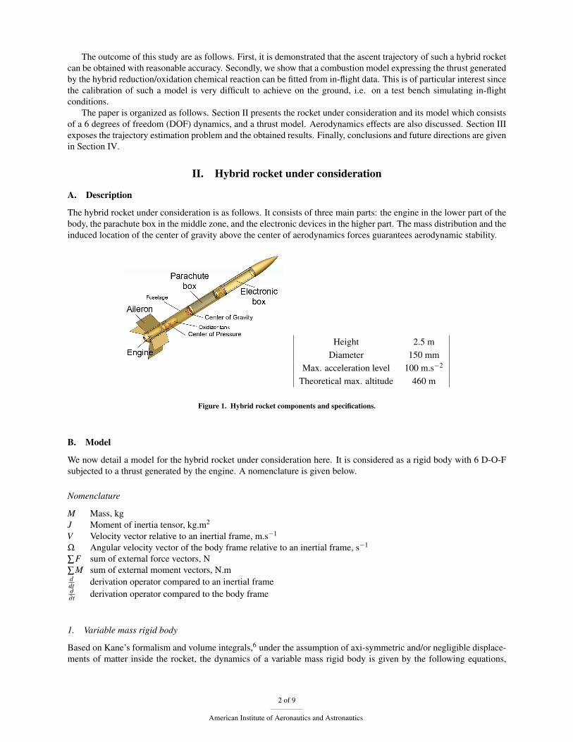
The hybrid rocket under consideration is as follows. It consists of three main parts: the engine in the lower part of thebody, the parachute box in the middle zone, and the electronic devices in the higher part. The mass distribution and theinduced location of the center of gravity above the center of aerodynamics forces guarantees aerodynamic stability.
Height 2.5 mDiameter 150 mm
Max. acceleration level 100 m.s−2
Theoretical max. altitude 460 m
Figure 1. Hybrid rocket components and specifications.
B. Model
We now detail a model for the hybrid rocket under consideration here. It is considered as a rigid body with 6 D-O-Fsubjected to a thrust generated by the engine. A nomenclature is given below.
Nomenclature
M Mass, kgJ Moment of inertia tensor, kg.m2
V Velocity vector relative to an inertial frame, m.s−1
Ω Angular velocity vector of the body frame relative to an inertial frame, s−1
∑F sum of external force vectors, N∑M sum of external moment vectors, N.mddt derivation operator compared to an inertial frame∂
∂ t derivation operator compared to the body frame
1. Variable mass rigid body
Based on Kane’s formalism and volume integrals,6 under the assumption of axi-symmetric and/or negligible displace-ments of matter inside the rocket, the dynamics of a variable mass rigid body is given by the following equations,
2 of 9
American Institute of Aeronautics and Astronautics
where V is the speed relative to an inertial frame of a fixed point of the rocket and CG is the vector distance of thispoint with respect to the center of gravity
M(
dVdt
+ Ω∧CG+Ω∧(Ω∧CG))
= ∑F +F t +Fc (1)
JdΩ
dt+
∂J∂ t
Ω = ∑M +Md (2)
The mass loss induces the force F t which is the thrust, the force Fc which is the Coriolis acceleration and themoment Md which is a damping moment.
In the case considered here, the maximum loss of max is relatively small compared to the total mass of the rocket.Therefore, the displacement of the center of gravity is small and slow, and one can neglect some terms compared tothe thrust. Under this assumption, the dynamics write
M(
∂V∂ t
+Ω∧V)
= ∑F +F t +Fc (3)
J∂Ω
∂ t+Ω∧JΩ+
∂J∂ t
Ω = ∑M +Md (4)
Among the external forces are the gravity, the pressure force which is applied at the nozzle exit, the aerodynamicforces which are applied at the center of pressure, and the force exerted by the parachute when it is deployed. Thevarious lever arms generate external torques. To determine the moment Md and the effect due to the inertia variationrequires the knowledge of the mass distribution during the combustion.
2. Thrust model: hybrid propulsion
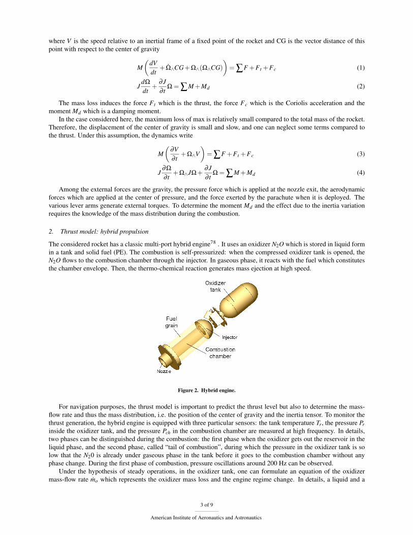
The considered rocket has a classic multi-port hybrid engine78 . It uses an oxidizer N2O which is stored in liquid formin a tank and solid fuel (PE). The combustion is self-pressurized: when the compressed oxidizer tank is opened, theN2O flows to the combustion chamber through the injector. In gaseous phase, it reacts with the fuel which constitutesthe chamber envelope. Then, the thermo-chemical reaction generates mass ejection at high speed.
Figure 2. Hybrid engine.
For navigation purposes, the thrust model is important to predict the thrust level but also to determine the mass-flow rate and thus the mass distribution, i.e. the position of the center of gravity and the inertia tensor. To monitor thethrust generation, the hybrid engine is equipped with three particular sensors: the tank temperature Tr, the pressure Prinside the oxidizer tank, and the pressure Pch in the combustion chamber are measured at high frequency. In details,two phases can be distinguished during the combustion: the first phase when the oxidizer gets out the reservoir in theliquid phase, and the second phase, called “tail of combustion”, during which the pressure in the oxidizer tank is solow that the N20 is already under gaseous phase in the tank before it goes to the combustion chamber without anyphase change. During the first phase of combustion, pressure oscillations around 200 Hz can be observed.
Under the hypothesis of steady operations, in the oxidizer tank, one can formulate an equation of the oxidizermass-flow rate mo which represents the oxidizer mass loss and the engine regime change. In details, a liquid and a
3 of 9
American Institute of Aeronautics and Astronautics
gaseous phase are modeled in the tank. The density ρo depends on the phase under which the oxidizer comes out thetank.
mo = k√
2ρo(Pr−Pch) (5)
Knowing the oxidizer mass-flow rate, one can compute the oxidizer mass flux Go and, then, the regression rate rof the fuel grain
Go =mo
Nπr2 (6)
r = aGno (7)
The model parameters a and n can be determined so that the regression rate verifies the initial and final conditions.This is how the fuel mass flux and the oxidizer-to-fuel ratio can be computed. Further, a thermo-chemical model,taking the form of look-up tables, gives the characteristic exhaust velocity c∗ and the specific impulse Isp as functionsof the oxidizer-to-fuel ratio and of the chamber pressure.
It can be checked that the ejected mass-flow rate is consistent with the total mass loss
me = Atg/c∗ (8)
where At is the throat cross-sectionnal area and g is the gravity.Finally, the theoretical thrust force is expressed as an indirect function of the measurements available on the engine.
This takes the following form
FT = meIspg , f (Tr,Pr,Pch) (9)
3. Aerodynamics
For this kind of small experimental rockets, the aerodynamic modeling is not essential. On one hand, drag effects arenegligible compared to the thrust force since the airspeed does not reach important values in a so short accelerationtime (less than 2 sec). On the other hand, transverse effects like incidence oscillations (short period mode) are dif-ficult to identify because of large uncertainties on aerodynamic parameters (like the lift coefficient) and mechanicalparameters (principally the inertia tensor). Fortunately, they are well visible on the gyrometers measurements. Thesesimplifications will surely need to be reconsidered when this work is transposed to larger rockets.
III. Trajectory estimation
We now expose how the previously discussed model can be used to estimate the actual trajectory of the rocketfrom available measurements.
A. A typical trajectory
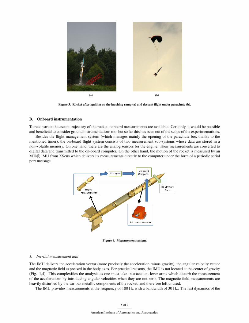
The trajectory of the rocket can be divided into four stages. The first one lasts until ignition. During this time period,the rocket is standing still on the launch-pad. It is possible to take advantage of this to calibrate the IMU sensors.During the second stage of the trajectory (Fig. 3a), the engine is on and the rocket is propelled and moving butremains on the launch ramp. The modeling of this period is quite uncertain due to unmodeled interactions with theramp. Fortunately, the time spent moving on the ramp is very short.
Then, the third and main stage is the ascent flight of the rocket which is propelled. During this stage, the rocketaccelerates before reaching its maximum velocity. Then, it slows down and reaches its peak altitude. Finally, theparachute is deployed at a time controlled by an onboard timer. Parachute deployment occurs 9 seconds after ignition.The predominant effect during this ascent stage is the thrust.
Finally, the fourth stage (Fig. 3b) is the descent flight when the rocket hangs under the parachute until its landing.During this period, the rocket and its parachute constitute a non-rigid flying object submitted to drag aerodynamicseffects whose coefficients are badly known.9 Further, the system is quite sensitive to wind disturbances. For thisreason, the fourth stage of the trajectory is not considered in the study.
4 of 9
American Institute of Aeronautics and Astronautics
(a) (b)
Figure 3. Rocket after ignition on the lauching ramp (a) and descent flight under parachute (b).
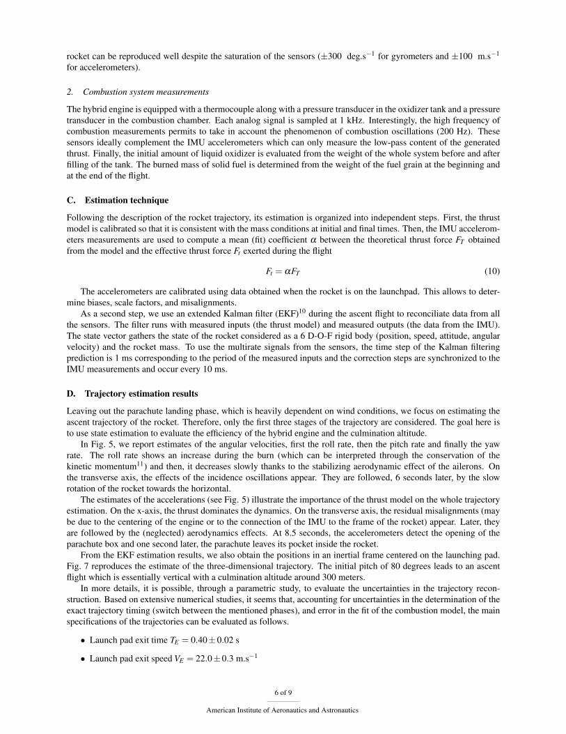
B. Onboard instrumentation
To reconstruct the ascent trajectory of the rocket, onboard measurements are available. Certainly, it would be possibleand beneficial to consider ground instrumentations too, but so far this has been out of the scope of the experimentations.
Besides the flight management system (which manages mainly the opening of the parachute box thanks to thementioned timer), the on-board flight system consists of two measurement sub-systems whose data are stored in anon-volatile memory. On one hand, there are the analog sensors for the engine. Their measurements are converted todigital data and transmitted to the on-board computer. On the other hand, the motion of the rocket is measured by anMTir IMU from XSens which delivers its measurements directly to the computer under the form of a periodic serialport message.
Figure 4. Measurement system.
1. Inertial measurement unit
The IMU delivers the acceleration vector (more precisely the acceleration minus gravity), the angular velocity vectorand the magnetic field expressed in the body axes. For practical reasons, the IMU is not located at the center of gravity(Fig. 1,4). This complexifies the analysis as one must take into account lever arms which disturb the measurementof the accelerations by introducing angular velocities when they are not zero. The magnetic field measurements areheavily disturbed by the various metallic components of the rocket, and therefore left unused.
The IMU provides measurements at the frequency of 100 Hz with a bandwidth of 30 Hz. The fast dynamics of the
5 of 9
American Institute of Aeronautics and Astronautics
rocket can be reproduced well despite the saturation of the sensors (±300 deg.s−1 for gyrometers and ±100 m.s−1
for accelerometers).
2. Combustion system measurements
The hybrid engine is equipped with a thermocouple along with a pressure transducer in the oxidizer tank and a pressuretransducer in the combustion chamber. Each analog signal is sampled at 1 kHz. Interestingly, the high frequency ofcombustion measurements permits to take in account the phenomenon of combustion oscillations (200 Hz). Thesesensors ideally complement the IMU accelerometers which can only measure the low-pass content of the generatedthrust. Finally, the initial amount of liquid oxidizer is evaluated from the weight of the whole system before and afterfilling of the tank. The burned mass of solid fuel is determined from the weight of the fuel grain at the beginning andat the end of the flight.
C. Estimation technique
Following the description of the rocket trajectory, its estimation is organized into independent steps. First, the thrustmodel is calibrated so that it is consistent with the mass conditions at initial and final times. Then, the IMU accelerom-eters measurements are used to compute a mean (fit) coefficient α between the theoretical thrust force FT obtainedfrom the model and the effective thrust force Ft exerted during the flight
Ft = αFT (10)
The accelerometers are calibrated using data obtained when the rocket is on the launchpad. This allows to deter-mine biases, scale factors, and misalignments.
As a second step, we use an extended Kalman filter (EKF)10 during the ascent flight to reconciliate data from allthe sensors. The filter runs with measured inputs (the thrust model) and measured outputs (the data from the IMU).The state vector gathers the state of the rocket considered as a 6 D-O-F rigid body (position, speed, attitude, angularvelocity) and the rocket mass. To use the multirate signals from the sensors, the time step of the Kalman filteringprediction is 1 ms corresponding to the period of the measured inputs and the correction steps are synchronized to theIMU measurements and occur every 10 ms.
D. Trajectory estimation results
Leaving out the parachute landing phase, which is heavily dependent on wind conditions, we focus on estimating theascent trajectory of the rocket. Therefore, only the first three stages of the trajectory are considered. The goal here isto use state estimation to evaluate the efficiency of the hybrid engine and the culmination altitude.
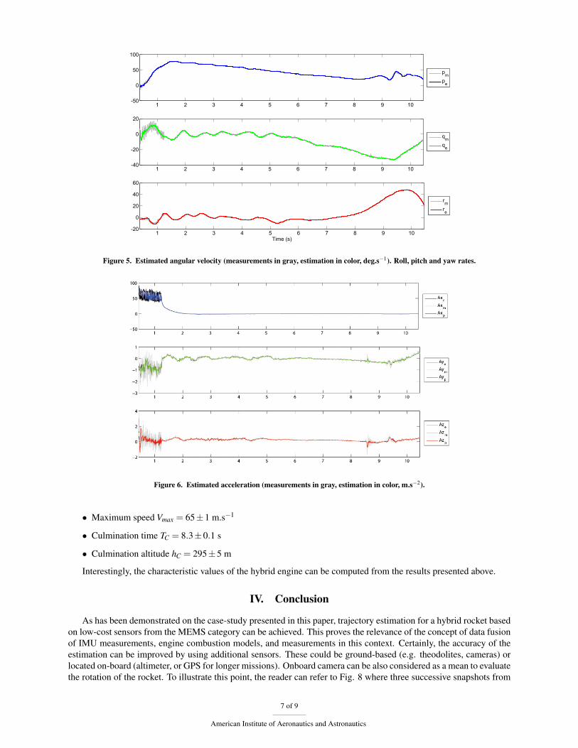
In Fig. 5, we report estimates of the angular velocities, first the roll rate, then the pitch rate and finally the yawrate. The roll rate shows an increase during the burn (which can be interpreted through the conservation of thekinetic momentum11) and then, it decreases slowly thanks to the stabilizing aerodynamic effect of the ailerons. Onthe transverse axis, the effects of the incidence oscillations appear. They are followed, 6 seconds later, by the slowrotation of the rocket towards the horizontal.
The estimates of the accelerations (see Fig. 5) illustrate the importance of the thrust model on the whole trajectoryestimation. On the x-axis, the thrust dominates the dynamics. On the transverse axis, the residual misalignments (maybe due to the centering of the engine or to the connection of the IMU to the frame of the rocket) appear. Later, theyare followed by the (neglected) aerodynamics effects. At 8.5 seconds, the accelerometers detect the opening of theparachute box and one second later, the parachute leaves its pocket inside the rocket.
From the EKF estimation results, we also obtain the positions in an inertial frame centered on the launching pad.Fig. 7 reproduces the estimate of the three-dimensional trajectory. The initial pitch of 80 degrees leads to an ascentflight which is essentially vertical with a culmination altitude around 300 meters.
In more details, it is possible, through a parametric study, to evaluate the uncertainties in the trajectory recon-struction. Based on extensive numerical studies, it seems that, accounting for uncertainties in the determination of theexact trajectory timing (switch between the mentioned phases), and error in the fit of the combustion model, the mainspecifications of the trajectories can be evaluated as follows.
• Launch pad exit time TE = 0.40±0.02 s
• Launch pad exit speed VE = 22.0±0.3 m.s−1
6 of 9
American Institute of Aeronautics and Astronautics
1 2 3 4 5 6 7 8 9 10-50
0
50
100
pmpe
1 2 3 4 5 6 7 8 9 10-40
-20
0
20
qmqe
1 2 3 4 5 6 7 8 9 10-20
0
20
40
60
Time (s)
rmre
Figure 5. Estimated angular velocity (measurements in gray, estimation in color, deg.s−1). Roll, pitch and yaw rates.
Figure 6. Estimated acceleration (measurements in gray, estimation in color, m.s−2).
• Maximum speed Vmax = 65±1 m.s−1
• Culmination time TC = 8.3±0.1 s
• Culmination altitude hC = 295±5 m
Interestingly, the characteristic values of the hybrid engine can be computed from the results presented above.
IV. Conclusion
As has been demonstrated on the case-study presented in this paper, trajectory estimation for a hybrid rocket basedon low-cost sensors from the MEMS category can be achieved. This proves the relevance of the concept of data fusionof IMU measurements, engine combustion models, and measurements in this context. Certainly, the accuracy of theestimation can be improved by using additional sensors. These could be ground-based (e.g. theodolites, cameras) orlocated on-board (altimeter, or GPS for longer missions). Onboard camera can be also considered as a mean to evaluatethe rotation of the rocket. To illustrate this point, the reader can refer to Fig. 8 where three successive snapshots from
7 of 9
American Institute of Aeronautics and Astronautics
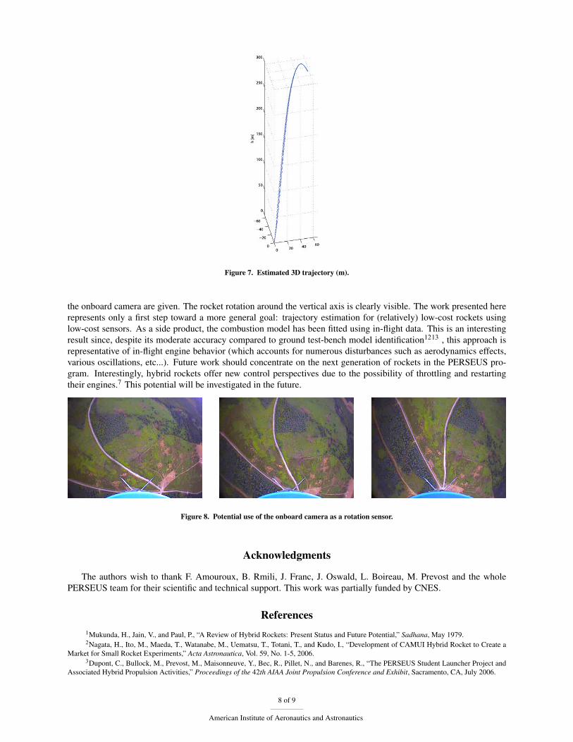
Figure 7. Estimated 3D trajectory (m).
the onboard camera are given. The rocket rotation around the vertical axis is clearly visible. The work presented hererepresents only a first step toward a more general goal: trajectory estimation for (relatively) low-cost rockets usinglow-cost sensors. As a side product, the combustion model has been fitted using in-flight data. This is an interestingresult since, despite its moderate accuracy compared to ground test-bench model identification1213 , this approach isrepresentative of in-flight engine behavior (which accounts for numerous disturbances such as aerodynamics effects,various oscillations, etc...). Future work should concentrate on the next generation of rockets in the PERSEUS pro-gram. Interestingly, hybrid rockets offer new control perspectives due to the possibility of throttling and restartingtheir engines.7 This potential will be investigated in the future.
Figure 8. Potential use of the onboard camera as a rotation sensor.
Acknowledgments
The authors wish to thank F. Amouroux, B. Rmili, J. Franc, J. Oswald, L. Boireau, M. Prevost and the wholePERSEUS team for their scientific and technical support. This work was partially funded by CNES.
References1Mukunda, H., Jain, V., and Paul, P., “A Review of Hybrid Rockets: Present Status and Future Potential,” Sadhana, May 1979.2Nagata, H., Ito, M., Maeda, T., Watanabe, M., Uematsu, T., Totani, T., and Kudo, I., “Development of CAMUI Hybrid Rocket to Create a
Market for Small Rocket Experiments,” Acta Astronautica, Vol. 59, No. 1-5, 2006.3Dupont, C., Bullock, M., Prevost, M., Maisonneuve, Y., Bec, R., Pillet, N., and Barenes, R., “The PERSEUS Student Launcher Project and
Associated Hybrid Propulsion Activities,” Proceedings of the 42th AIAA Joint Propulsion Conference and Exhibit, Sacramento, CA, July 2006.
8 of 9
American Institute of Aeronautics and Astronautics
4Titterton, D. and Weston, J., Strapdown Inertial Navigation Technology, The American Institute of Aeronautics and Aeronautics, 2nd ed.,2004.
5Schulze, K. and Meyer, S., “The Rapid and Low-Cost Development of a Hybrid Rocket Motor,” Proceedings of the 29th AIAA JointPropulsion Conference and Exhibit, Monterey, CA, June 1993.
6Eke, F., “Dynamics of Variable Mass Systems,” Tech. rep., Departement of Mechanical and Aeronautical Engineering, University of Cali-fornia, CA, 1999.
7Humble, R., Henry, G., and Larson, W., Space Propulsion Analysis and Design, The McGraw-Hill Companies Inc., 1995.8Chiaverini, M. and Kuo, K., editors, Fundamentals of Hybrid Rocket Combustion and Propulsion, American Institute of Aeronautics and
Astronautics, Inc., 2007.9Dobrokhodov, V., Yakimenko, O., and C.J.Junge, “Six-Degree-Of-Freedom Model of a Controlled Circular Parachute,” Journal of Aircraft,
Vol. 40, No. 3, June 2003.10Stengel, R., Optimal Control and Estimation, General Publishing Company, Ltd., 2nd ed., 1994.11Eke, F., Mao, T.-C., and Morris, M., “Free Attitude Motions of a Spinning Body with Substantial Mass Loss,” Journal of Applied Mechanics,
Vol. 71, No. 2, March 2004.12Lohner, K., Dyer, J., Doran, E., Dunn, Z., and Zilliac, G., “Fuel Regression Rate Characterization Using a Laboratory Scale Nitrous Oxide
Hybrid Propulsion System,” Proceedings of the 42th AIAA Joint Propulsion Conference and Exhibit, Sacramento, CA, July 2006.13Stamatov, V., Honnery, D., and Soria, J., “Visualization of Flow Development in Hybrid Rocket Motors with High Regression Rates,”
Journal of Propulsion and Power, Vol. 21, No. 4, 2005.
9 of 9
American Institute of Aeronautics and Astronautics