TP series - Scorpion Oceanics Ltd TP-Series.pdf · Civil construction • bridges • roads ... TP...
29
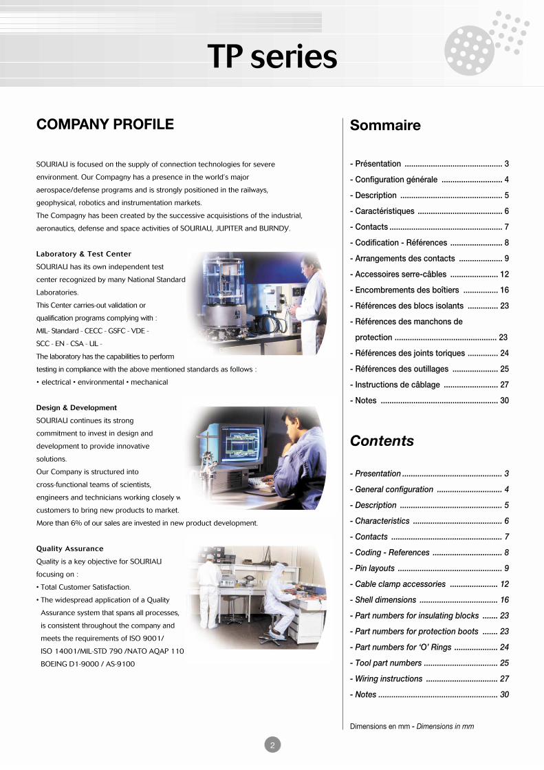
TP series 2 Sommaire - Présentation ............................................. 3 - Configuration générale ............................ 4 - Description ............................................... 5 - Caractéristiques ....................................... 6 - Contacts .................................................... 7 - Codification - Références ........................ 8 - Arrangements des contacts .................... 9 - Accessoires serre-câbles ...................... 12 - Encombrements des boîtiers ................ 16 - Références des blocs isolants .............. 23 - Références des manchons de protection ............................................... 23 - Références des joints toriques .............. 24 - Références des outillages ..................... 25 - Instructions de câblage ......................... 27 - Notes ...................................................... 30 Contents - Presentation .............................................. 3 - General configuration .............................. 4 - Description ............................................... 5 - Characteristics ......................................... 6 - Contacts ................................................... 7 - Coding - References ................................ 8 - Pin layouts ................................................ 9 - Cable clamp accessories ...................... 12 - Shell dimensions .................................... 16 - Part numbers for insulating blocks ....... 23 - Part numbers for protection boots ....... 23 - Part numbers for ‘O’ Rings .................... 24 - Tool part numbers .................................. 25 - Wiring instructions ................................. 27 - Notes ....................................................... 30 Dimensions en mm - Dimensions in mm COMPANY PROFILE SOURIAU is focused on the supply of connection technologies for severe environment. Our Compagny has a presence in the world’s major aerospace/defense programs and is strongly positioned in the railways, geophysical, robotics and instrumentation markets. The Compagny has been created by the successive acquisistions of the industrial, aeronautics, defense and space activities of SOURIAU, JUPITER and BURNDY. Laboratory & Test Center SOURIAU has its own independent test center recognized by many National Standard Laboratories. This Center carries-out validation or qualification programs complying with : MIL- Standard - CECC - GSFC - VDE - SCC - EN - CSA - UL - The laboratory has the capabilities to perform testing in compliance with the above mentioned standards as follows : • electrical • environmental • mechanical Design & Development SOURIAU continues its strong commitment to invest in design and development to provide innovative solutions. Our Company is structured into cross-functional teams of scientists, engineers and technicians working closely with customers to bring new products to market. More than 6% of our sales are invested in new product development. Quality Assurance Quality is a key objective for SOURIAU focusing on : • Total Customer Satisfaction. • The widespread application of a Quality Assurance system that spans all processes, is consistent throughout the company and meets the requirements of ISO 9001/ ISO 14001/MIL-STD 790 /NATO AQAP 110 / BOEING D1-9000 / AS-9100
Transcript of TP series - Scorpion Oceanics Ltd TP-Series.pdf · Civil construction • bridges • roads ... TP...
TP series
2
Sommaire
- Présentation ............................................. 3
- Configuration générale ............................ 4
- Description ............................................... 5
- Caractéristiques ....................................... 6
- Contacts .................................................... 7
- Codification - Références ........................ 8
- Arrangements des contacts .................... 9
- Accessoires serre-câbles ...................... 12
- Encombrements des boîtiers ................ 16
- Références des blocs isolants .............. 23
- Références des manchons de
protection ............................................... 23
- Références des joints toriques .............. 24
- Références des outillages ..................... 25
- Instructions de câblage ......................... 27
- Notes ...................................................... 30
Contents
- Presentation .............................................. 3
- General configuration .............................. 4
- Description ............................................... 5
- Characteristics ......................................... 6
- Contacts ................................................... 7
- Coding - References ................................ 8
- Pin layouts ................................................ 9
- Cable clamp accessories ...................... 12
- Shell dimensions .................................... 16
- Part numbers for insulating blocks ....... 23
- Part numbers for protection boots ....... 23
- Part numbers for ‘O’ Rings .................... 24
- Tool part numbers .................................. 25
- Wiring instructions ................................. 27
- Notes ....................................................... 30
Dimensions en mm - Dimensions in mm
COMPANY PROFILE
SOURIAU is focused on the supply of connection technologies for severe
environment. Our Compagny has a presence in the world’s major
aerospace/defense programs and is strongly positioned in the railways,
geophysical, robotics and instrumentation markets.
The Compagny has been created by the successive acquisistions of the industrial,
aeronautics, defense and space activities of SOURIAU, JUPITER and BURNDY.
Laboratory & Test Center
SOURIAU has its own independent test
center recognized by many National Standard
Laboratories.
This Center carries-out validation or
qualification programs complying with :
MIL- Standard - CECC - GSFC - VDE -
SCC - EN - CSA - UL -
The laboratory has the capabilities to perform
testing in compliance with the above mentioned standards as follows :
• electrical • environmental • mechanical
Design & Development
SOURIAU continues its strong
commitment to invest in design and
development to provide innovative
solutions.
Our Company is structured into
cross-functional teams of scientists,
engineers and technicians working closely with
customers to bring new products to market.
More than 6% of our sales are invested in new product development.
Quality Assurance
Quality is a key objective for SOURIAU
focusing on :
• Total Customer Satisfaction.
• The widespread application of a Quality
Assurance system that spans all processes,
is consistent throughout the company and
meets the requirements of ISO 9001/
ISO 14001/MIL-STD 790 /NATO AQAP 110 /
BOEING D1-9000 / AS-9100

TP series
PrésentationLes connecteurs de la série TP sont similaires à ceux de lagamme marine immergée M mais avec des boîtiers en laitonnickelés-chromés. Ils sont particulièrement destinés aux besoinsde l'industrie pour des produits étanches en environnementhostile. Les principales caractéristiques de cette série sont :
PresentationThe TP series connectors are simi lar to those of the Msubmerged marine product range but use nickel-chrome platedbrass shells. They are especially designed for industry require-ments concerning watertight products in harsh environment. Themain characteristics of this series are:
Applications types / Typical applications
Géophysique• analyse séismique• fracturation du sol• cimentation• instrumentation• détection acoustiqueGeophysics• seismic analysis• ground fracturing• cementing• instrumentation• acoustic sensing
Instrumentation sous-marine• hydrophones• caméras• capteurs• R.O.V.• bouéesUnderwater instrumentation• hydrophones• cameras• sensors• R.O.V.• buoys
Traitement des eaux• pompes• vannes• filtration• épuration• égoutsWater treatment• pumps• valves• filtration• purification• sewage system
Industrie lourde• chantier naval• pétrochimie• aciérie• environnement• énergieHeavy industry• shipyards• petrochemicals• steelworks• environment• power
Transport ferré• détecteurs de trafic• balisage de voie• antenne• commande de freins• signalisationRail transportation• trafic detectors• track lights• antenna• brake controls• signalling
Construction civile• ponts• routes, autoroutes• barrages• bâtiment• tunnelCivil construction• bridges• roads, highways• dams• buildings• tunnels
• étanché ité à l ' immersion jusqu'à 300 mètres deprofondeur,
• conception très robuste avec résistance à la corrosion,• boîtiers scoop-proof,• détrompage mécanique par 5 clés,• simplicité de mise en œuvre et totalement réparable sur
site,• excelllent comportement aux huiles, gaz, sable, boue,
hydrocarbures, sels, déchets naturels ou abus humains.
• waterproof when immersed down to 300 meters indepth,
• rugged construction with resistance to corrosion,• scoop-proof shells,• 5-key mechanical polarization,• simple to set up and fully field repairable,• capable of prolonged use in presence of oil, gas, sand,
mud, hydrocarbons, salts, natural waste or humanabuse.
3
TP series
4
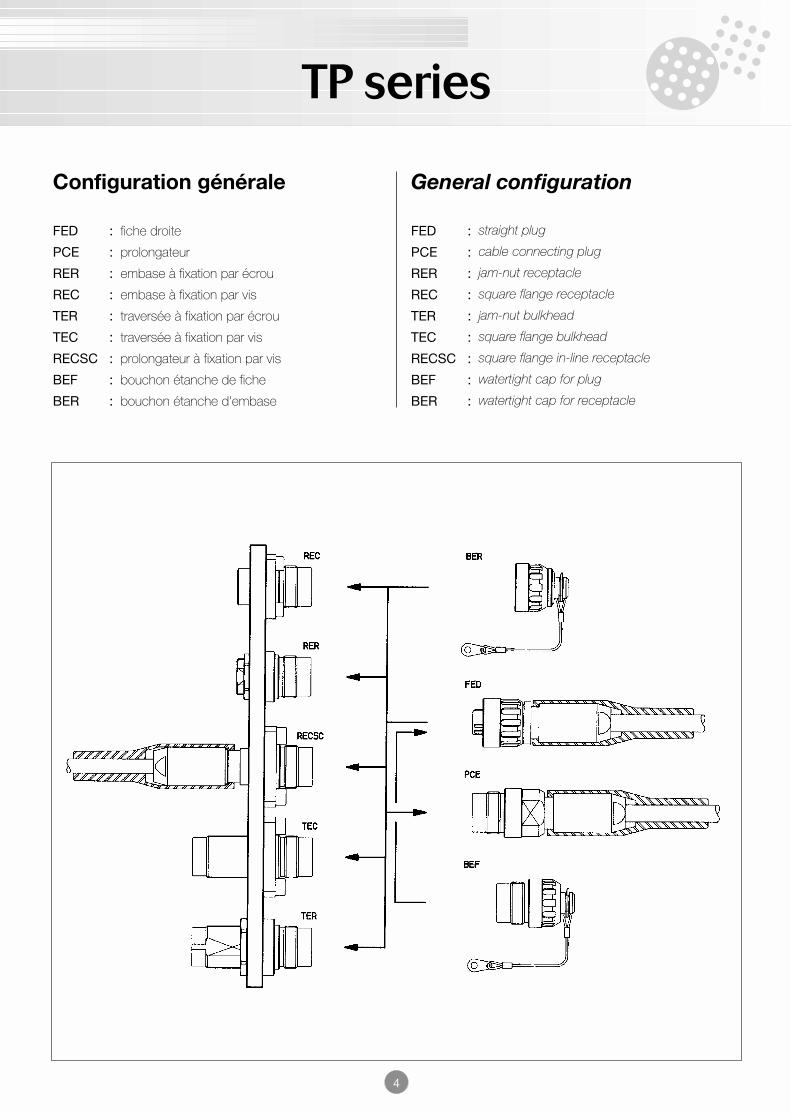
Configuration générale
FED : fiche droite
PCE : prolongateur
RER : embase à fixation par écrou
REC : embase à fixation par vis
TER : traversée à fixation par écrou
TEC : traversée à fixation par vis
RECSC : prolongateur à fixation par vis
BEF : bouchon étanche de fiche
BER : bouchon étanche d'embase
General configuration
FED : straight plug
PCE : cable connecting plug
RER : jam-nut receptacle
REC : square flange receptacle
TER : jam-nut bulkhead
TEC : square flange bulkhead
RECSC : square flange in-line receptacle
BEF : watertight cap for plug
BER : watertight cap for receptacle
TP series
5
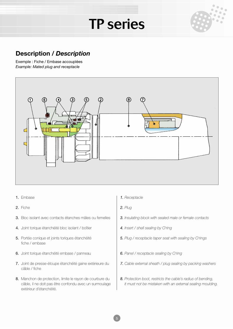
Description / DescriptionExemple : Fiche / Embase accoupléesExample: Mated plug and receptacle
1. Embase
2. Fiche
3. Bloc isolant avec contacts étanches mâles ou femelles
4. Joint torique étanchéité bloc isolant / boîtier
5. Portée conique et joints toriques étanchéitéfiche / embase
6. Joint torique étanchéité embase / panneau
7. Joint de presse-étoupe étanchéité gaine extérieure ducâble / fiche
8. Manchon de protection, limite le rayon de courbure ducâble, il ne doit pas être confondu avec un surmoulageextérieur d'étanchéité.
1. Receptacle
2. Plug
3. Insulating block with sealed male or female contacts
4. Insert / shell sealing by O'ring
5. Plug / receptacle taper seat with sealing by O'rings
6. Panel / receptacle sealing by O'ring
7. Cable external sheath / plug sealing by packing washers
8. Protection boot, restricts the cable’s radius of bending,it must not be mistaken with an external sealing moulding.
TP series
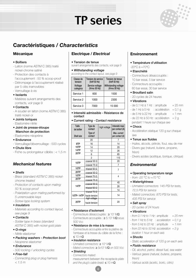
Classe de Tension de service Tension de tenuetension (Veff 50 Hz) (Veff 50 Hz)Voltage Service voltage Withstanding voltagecategory (Vrms 50 Hz) (Vrms 50 Hz)
Service 1 600 1500
Service 2 1000 2300
Service 3 7000 15 000
Caractéristiques / Characteristics
Mécanique
• Boîtiers- Laiton (norme ASTM C 385) traité
nickel-chrome satiné- Protection des contacts à
l'accouplement : 50 % scoop-proof- Détrompage à l'accouplement réalisé
par 5 clés inamovibles- Verrouillage à vis• Isolants- Matières suivant arrangements des
contacts, voir page 9• Contacts- A souder en laiton (norme ASTM C 385)
traité nickel-or• Joints toriques- Elastomère nitrile• Joint de presse-étoupe
Manchon de protection- Elastomère néoprène• Endurance- Verrouillage/déverrouillage : 500 cycles• Chute libre- Fiche ou prolongateur câblés : < 1,5 m
Mechanical features
• Shells- Brass (standard ASTM C 385) nickel-
chrome treated- Protection of contacts upon mating:
50 % scoop-proof- Polarization upon mating performed by
5 unremovable keys- Screw-type locking system• Insulators- Materials according to contact layout,
see page 9• Contacts- Solder type in brass (standard
ASTM C 385) with nickel-gold plate• O-rings- Nitrile elastomer• Packing washers - Protection boot- Neoprene elastomer• Endurance- 500 locking / unlocking cycles• Free-fall- Connecting plug or plug harness
< 1.5 m
Electrique / Electrical
• Tension de tenuesuivant arrangements des contacts, voir page 9
• Withstanding voltageaccording to the contact layout, see page 9
Environnement
• Température d'utilisation-20°C à +70°C• Etanchéité- Connecteurs désaccouplés :
10 bar essai, 5 bar service- Connecteurs accouplés :
60 bar essai, 30 bar service• Brouillard salin- 20 cycles de 24 heures• Vibrations- de 0,1 Hz à 1 Hz : amplitude = 25 mm- de 1 Hz à 5 Hz : accélération = 0,1 g- de 5 Hz à 22 Hz : amplitude = 1 mm- de 22 Hz à 50 Hz : accélération = 2 gpendant 1 heure sur chaque axe
• Chocs- Accélération statique 120 g sur chaque
axe• Tenue aux fluides- Huiles, alcools, pétrole, fioul, eau de mer- Divers gaz (naturel, butane, propane,
fréon)- Divers acides (acétique, borique, citrique)
Environmental
• Operating temperature range- from -20 °C to +70 °C• Watertightness- Unmated connectors: 145 PSI for tests,
72,5 PSI for service- Mated connectors: 870 PSI for tests,
435 PSI for service• Salt spray- 20 cycles of 24 hours• Vibrations- from 0.1 Hz to 1 Hz : amplitude = 25 mm- from 1 Hz to 5 Hz : acceleration = 0,1 g- from 5 Hz to 22 Hz : amplitude = 1 mm- from 22 Hz to 50 Hz: acceleration = 2 gduration 1 hour on each axis
• Shocks- Static acceleration of 120 g on each axis• Fluids resistance- Oil, alcohol, petrol, diesel fuel, sea water- Various gases (natural, butane, propane,
freon)- Various acids (acetic, boric, citric)
Taillede boîtier
Shell size
8TP10TP14TP20TP
10TP
10TP20TP10TP20TP
14TP
10TP- 14TP
20TP
Type decontactType ofcontact
2016141262
coaxial 50 Ωcoaxial 75 Ωtriaxial 50 Ωcoaxial 50 Ωtriaxial 75 Ωcoaxial 75 Ωcoaxial 50 Ωtriaxial 50 Ωtriaxial 75 Ωhaute tensionhigh voltage
haute tension
high voltage Intensité maxipar contact (A)
Max. currentper contact (A)
714202665
115207
7
4
402614
14
20
• Intensité admissible - Résistance decontact
• Current rating - Contact resistance
• Résistance d'isolement- Connecteurs désaccouplés : ≥ 104 MΩ- Connecteurs accouplés : ≥ 5.103 MΩ sous
500 Vcc• Résistance de mise à la masse- Connecteurs accouplés entre la platine de
l'embase et la tresse du câble de la fiche :≤ 10 mΩ
• Insulation resistance- Unmated connectors: ≥ 104 MΩ- Mated connectors: ≥ 5x10³ MΩ on 500 Vcc• Shielding- Connectors mated:measurement between the receptacle plateand the plug’s cable braid: ≤ 10 mΩ
6
TP series
7
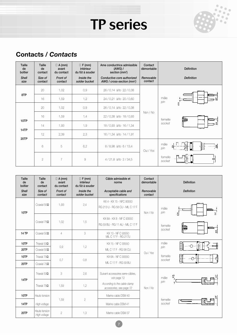
Contacts / Contacts
Taille Taille ∅ A (mm) ∅ F (mm) Ame conductrice admissible Contactde de avant intérieur (AWG) / démontable Définition
boîtier contact du contact du fût à souder section (mm2)
Shell Size of Front of Inside the Conductive core authorized Removable Definitionsize contact contact solder bucket AWG / cross-section (mm2) contact
20 1,02 0,9 26 / 0,14 à/to 22 / 0,38
8TP16 1,59 1,2 24 / 0,21 à/to 20 / 0,60
20 1,02 0,9 26 / 0,14 à/to 22 / 0,38
Non / No16 1,59 1,4 22 / 0,38 à/to 18 / 0,93
10TP
14 1,93 1,9 18 / 0,93 à/to 16 / 1,3414TP
12 2,39 2,3 16 / 1,34 à/to 14 / 1,9120TP
6 5 6,2 8 / 8,98 à/to 6 / 13,4Oui / Yes
2 7 9 4 / 21,8 à/to 2 / 34,5
Taille Taille ∅ A (mm) ∅ F (mm) Câble admissible et Contactde de avant intérieur norme démontable Définition
boîtier contact du contact du fût à souder
Shell Size of Front of Inside the Acceptable cable and Removable Definitionsize contact contact solder bucket specifications contact
Coaxial 50Ω 1,93 2,4KX 4 - KX 15 - NFC 93550
RG 213 U - RG 58 CU - MIL C 17 F
10TP Non / No
Coaxial 75Ω 1,02 1,5KX 6A - KX 8 - NF C 93550
RG 59 BU - RG 11 AU - MIL C 17 F
14 TP Coaxial 50Ω 4 3 KX 13 - NF C 93550MIL C 17 F - RG 217U
10TP Triaxial 50Ω0,9 1,2
KX 15 - NF C 93550
20TP Coaxial 50Ω MIL C 17 F - RG 58 CUOui / Yes
10TP Triaxial 75Ω0,7 0,8
KX 6A - NF C 93550
20TP Coaxial 75Ω MIL C 17 F - RG 59 BU
Triaxial 50Ω 3 2,6 Suivant accessoires serre-câbles,
14TPvoir page 12
Triaxial 75Ω 1,59 1,2According to the cable clamp
accessories, see page 12 Non / No
10TP Haute tension1,59 2
Marine cable DSM 40
14TP High voltage Marine cable DSM 41
20TPHaute tension
2 1,3 Marine cable DSM 37High voltage
mâlepin
mâlepin
mâlepin
mâlepin
mâlepin
femellesocket
femelle socket
femelle socket
femelle socket
femellesocket
TP series
3568
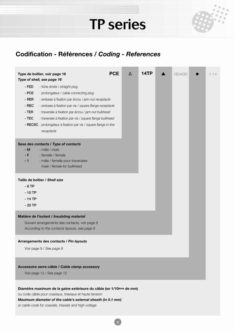
Diamètre maximum de la gaine extérieure du câble (en 1/10ème de mm)
ou code câble pour coaxiaux, triaxiaux et haute tension
Maximum diameter of the cable's external sheath (in 0.1 mm)
or cable code for coaxials, triaxials and high voltage
P
Accessoire serre-câble / Cable clamp accessory
Voir page 12 / See page 12
3568
Arrangements des contacts / Pin layouts
Voir page 9 / See page 9
Matière de l'isolant / Insulating material
Suivant arrangements des contacts, voir page 9
According to the contacts layouts, see page 9
8
14TP
Taille de boîtier / Shell size
- 8 TP
- 10 TP
- 14 TP
- 20 TP
Sexe des contacts / Type of contacts
- M : mâle / male
- F : femelle / female
- 1 : mâle / femelle pour traversées
male / female for bulkhead
Type de boîtier, voir page 16 PCEType of shell, see page 16
- FED : fiche droite / straight plug
- PCE : prolongateur / cable connecting plug
- RER : embase à fixation par écrou / jam-nut receptacle
- REC : embase à fixation par vis / square flange receptacle
- TER : traversée à fixation par écrou / jam-nut bulkhead
- TEC : traversée à fixation par vis / square flange bulkhead
- RECSC : prolongateur à fixation par vis / square flange in-line
receptacle
Codification - Références / Coding - References
∆
TP series
9
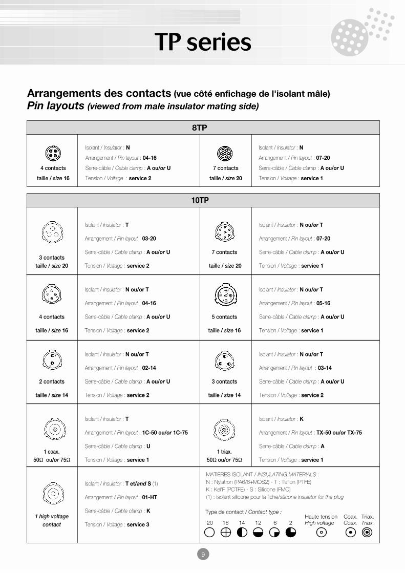
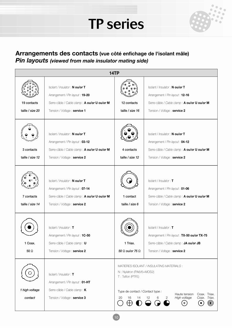
Arrangements des contacts (vue côté enfichage de l'isolant mâle)Pin layouts (viewed from male insulator mating side)
MATIERES ISOLANT / INSULATING MATERIALS :N : Nylatron (PA6/6+MOS2) - T : Teflon (PTFE)K : Kel'F (PCTFE) - S : Silicone (FMQ)(1) : isolant silicone pour la fiche/silicone insulator for the plug
8TP
Isolant / Insulator : N Isolant / Insulator : N
Arrangement / Pin layout : 04-16 Arrangement / Pin layout : 07-20
4 contacts Serre-câble / Cable clamp : A ou/or U 7 contacts Serre-câble / Cable clamp : A ou/or U
taille / size 16 Tension / Voltage : service 2 taille / size 20 Tension / Voltage : service 1
10TP
Isolant / Insulator : T Isolant / Insulator : N ou/or T
Arrangement / Pin layout : 03-20 Arrangement / Pin layout : 07-20
3 contactsSerre-câble / Cable clamp : A ou/or U 7 contacts Serre-câble / Cable clamp : A ou/or U
taille / size 20 Tension / Voltage : service 2 taille / size 20 Tension / Voltage : service 1
Isolant / Insulator : N ou/or T Isolant / Insulator : N ou/or T
Arrangement / Pin layout : 04-16 Arrangement / Pin layout : 05-16
4 contacts Serre-câble / Cable clamp : A ou/or U 5 contacts Serre-câble / Cable clamp : A ou/or U
taille / size 16 Tension / Voltage : service 2 taille / size 16 Tension / Voltage : service 1
Isolant / Insulator : N ou/or T Isolant / Insulator : N ou/or T
Arrangement / Pin layout : 02-14 Arrangement / Pin layout : 03-14
2 contacts Serre-câble / Cable clamp : A ou/or U 3 contacts Serre-câble / Cable clamp : A ou/or U
taille / size 14 Tension / Voltage : service 2 taille / size 14 Tension / Voltage : service 2
Isolant / Insulator : T Isolant / Insulator : K
Arrangement / Pin layout : 1C-50 ou/or 1C-75 Arrangement / Pin layout : TX-50 ou/or TX-75
1 coax.Serre-câble / Cable clamp : U
1 triax.Serre-câble / Cable clamp : A
50Ω ou/or 75Ω Tension / Voltage : service 1 50Ω ou/or 75Ω Tension / Voltage : service 1
Isolant / Insulator : T et/and S (1)
Arrangement / Pin layout : 01-HT
1 high voltageSerre-câble / Cable clamp : K
contact Tension / Voltage : service 3
TP series
14TP
Isolant / Insulator : N ou/or T Isolant / Insulator : N ou/or T
Arrangement / Pin layout : 19-20 Arrangement / Pin layout : 12-16
19 contacts Serre-câble / Cable clamp : A ou/or U ou/or M 12 contacts Serre-câble / Cable clamp : A ou/or U ou/or M
taille / size 20 Tension / Voltage : service 1 taille / size 16 Tension / Voltage : service 2
Isolant / Insulator : N ou/or T Isolant / Insulator : N ou/or T
Arrangement / Pin layout : 03-12 Arrangement / Pin layout : 04-12
3 contacts Serre-câble / Cable clamp : A ou/or U ou/or M 4 contacts Serre-câble / Cable clamp : A ou/or U ou/or M
taille / size 12 Tension / Voltage : service 2 taille / size 12 Tension / Voltage : service 2
Isolant / Insulator : N ou/or T Isolant / Insulator : T
Arrangement / Pin layout : 07-14 Arrangement / Pin layout : 01-06
7 contacts Serre-câble / Cable clamp : A ou/or U ou/or M 1 contact Serre-câble / Cable clamp : A ou/or U ou/or M
taille / size 14 Tension / Voltage : service 2 taille / size 6 Tension / Voltage : service 2
Isolant / Insulator : T Isolant / Insulator : T
Arrangement / Pin layout : 1C-50 Arrangement / Pin layout : TX-50 ou/or TX-75
1 Coax. Serre-câble / Cable clamp : U 1 Triax. Serre-câble / Cable clamp : JA ou/or JB
50 Ω Tension / Voltage : service 2 50 Ω ou/or 75 Ω Tension / Voltage : service 2
Isolant / Insulator : T
Arrangement / Pin layout : 01-HT
1 high voltage Serre-câble / Cable clamp : K
contact Tension / Voltage : service 3
10
Arrangements des contacts (vue côté enfichage de l'isolant mâle)Pin layouts (viewed from male insulator mating side)
MATIERES ISOLANT / INSULATING MATERIALS :
N : Nylatron (PA6/6+MOS2)
T : Teflon (PTFE)
TP series
11
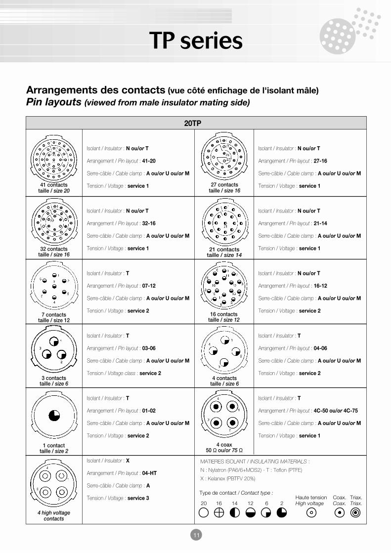
Arrangements des contacts (vue côté enfichage de l'isolant mâle)Pin layouts (viewed from male insulator mating side)
MATIERES ISOLANT / INSULATING MATERIALS :
N : Nylatron (PA6/6+MOS2) - T : Teflon (PTFE)
X : Kelanex (PBTFV 20%)
41 contactstaille / size 20
32 contactstaille / size 16
7 contactstaille / size 12
3 contactstaille / size 6
1 contacttaille / size 2
4 high voltagecontacts
4 coax50 Ω ou/or 75 Ω
4 contactstaille / size 6
16 contactstaille / size 12
21 contactstaille / size 14
27 contactstaille / size 16
20TP
Isolant / Insulator : N ou/or T Isolant / Insulator : N ou/or T
Arrangement / Pin layout : 41-20 Arrangement / Pin layout : 27-16
Serre-câble / Cable clamp : A ou/or U ou/or M Serre-câble / Cable clamp : A ou/or U ou/or M
Tension / Voltage : service 1 Tension / Voltage : service 1
Isolant / Insulator : N ou/or T Isolant / Insulator : N ou/or T
Arrangement / Pin layout : 32-16 Arrangement / Pin layout : 21-14
Serre-câble / Cable clamp : A ou/or U ou/or M Serre-câble / Cable clamp : A ou/or U ou/or M
Tension / Voltage : service 1 Tension / Voltage : service 1
Isolant / Insulator : T Isolant / Insulator : N ou/or T
Arrangement / Pin layout : 07-12 Arrangement / Pin layout : 16-12
Serre-câble / Cable clamp : A ou/or U ou/or M Serre-câble / Cable clamp : A ou/or U ou/or M
Tension / Voltage : service 2 Tension / Voltage : service 2
Isolant / Insulator : T Isolant / Insulator : T
Arrangement / Pin layout : 03-06 Arrangement / Pin layout : 04-06
Serre-câble / Cable clamp : A ou/or U ou/or M Serre-câble / Cable clamp : A ou/or U ou/or M
Tension / Voltage class : service 2 Tension / Voltage : service 2
Isolant / Insulator : T Isolant / Insulator : T
Arrangement / Pin layout : 01-02 Arrangement / Pin layout : 4C-50 ou/or 4C-75
Serre-câble / Cable clamp : A ou/or U ou/or M Serre-câble / Cable clamp : A ou/or U ou/or M
Tension / Voltage : service 2 Tension / Voltage : service 1
Isolant / Insulator : X
Arrangement / Pin layout : 04-HT
Serre-câble / Cable clamp : A
Tension / Voltage : service 3
TP series
12
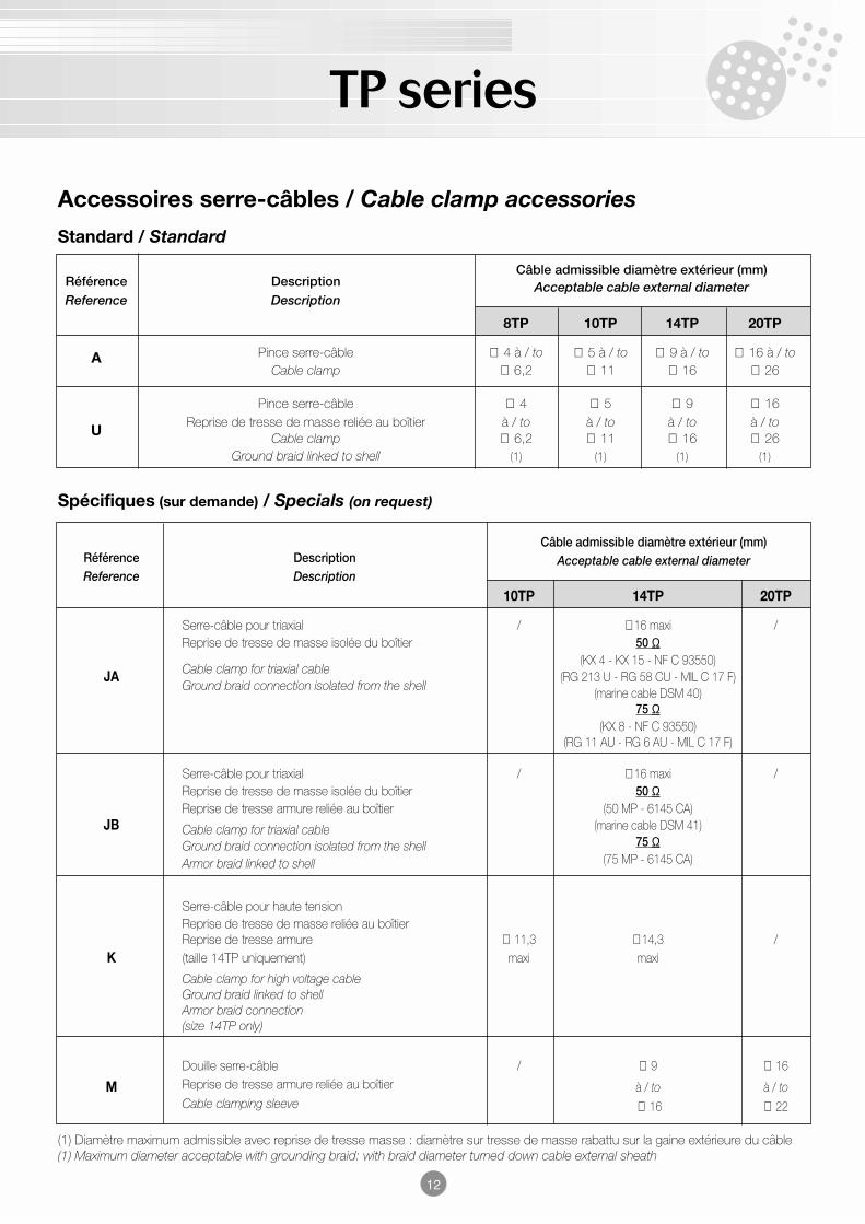
Accessoires serre-câbles / Cable clamp accessories
Référence DescriptionCâble admissible diamètre extérieur (mm)
Reference DescriptionAcceptable cable external diameter
8TP 10TP 14TP 20TP
A Pince serre-câble ∅ 4 à / to ∅ 5 à / to ∅ 9 à / to ∅ 16 à / toCable clamp ∅ 6,2 ∅ 11 ∅ 16 ∅ 26
Pince serre-câble ∅ 4 ∅ 5 ∅ 9 ∅ 16
UReprise de tresse de masse reliée au boîtier à / to à / to à / to à / to
Cable clamp ∅ 6,2 ∅ 11 ∅ 16 ∅ 26Ground braid linked to shell (1) (1) (1) (1)
(1) Diamètre maximum admissible avec reprise de tresse masse : diamètre sur tresse de masse rabattu sur la gaine extérieure du câble(1) Maximum diameter acceptable with grounding braid: with braid diameter turned down cable external sheath
Standard / Standard
Spécifiques (sur demande) / Specials (on request)
Câble admissible diamètre extérieur (mm)Référence Description Acceptable cable external diameterReference Description
10TP 14TP 20TP
Serre-câble pour triaxial / ∅ 16 maxi /Reprise de tresse de masse isolée du boîtier 50 Ω
Cable clamp for triaxial cable(KX 4 - KX 15 - NF C 93550)
JAGround braid connection isolated from the shell
(RG 213 U - RG 58 CU - MIL C 17 F)(marine cable DSM 40)
75 Ω(KX 8 - NF C 93550)
(RG 11 AU - RG 6 AU - MIL C 17 F)
Serre-câble pour triaxial / ∅ 16 maxi /Reprise de tresse de masse isolée du boîtier 50 ΩReprise de tresse armure reliée au boîtier (50 MP - 6145 CA)
JB Cable clamp for triaxial cable (marine cable DSM 41)
Ground braid connection isolated from the shell 75 Ω
Armor braid linked to shell (75 MP - 6145 CA)
Serre-câble pour haute tensionReprise de tresse de masse reliée au boîtierReprise de tresse armure ∅ 11,3 ∅ 14,3 /
K (taille 14TP uniquement) maxi maxi
Cable clamp for high voltage cableGround braid linked to shellArmor braid connection(size 14TP only)
Douille serre-câble / ∅ 9 ∅ 16
M Reprise de tresse armure reliée au boîtier à / to à / toCable clamping sleeve ∅ 16 ∅ 22
TP series
13
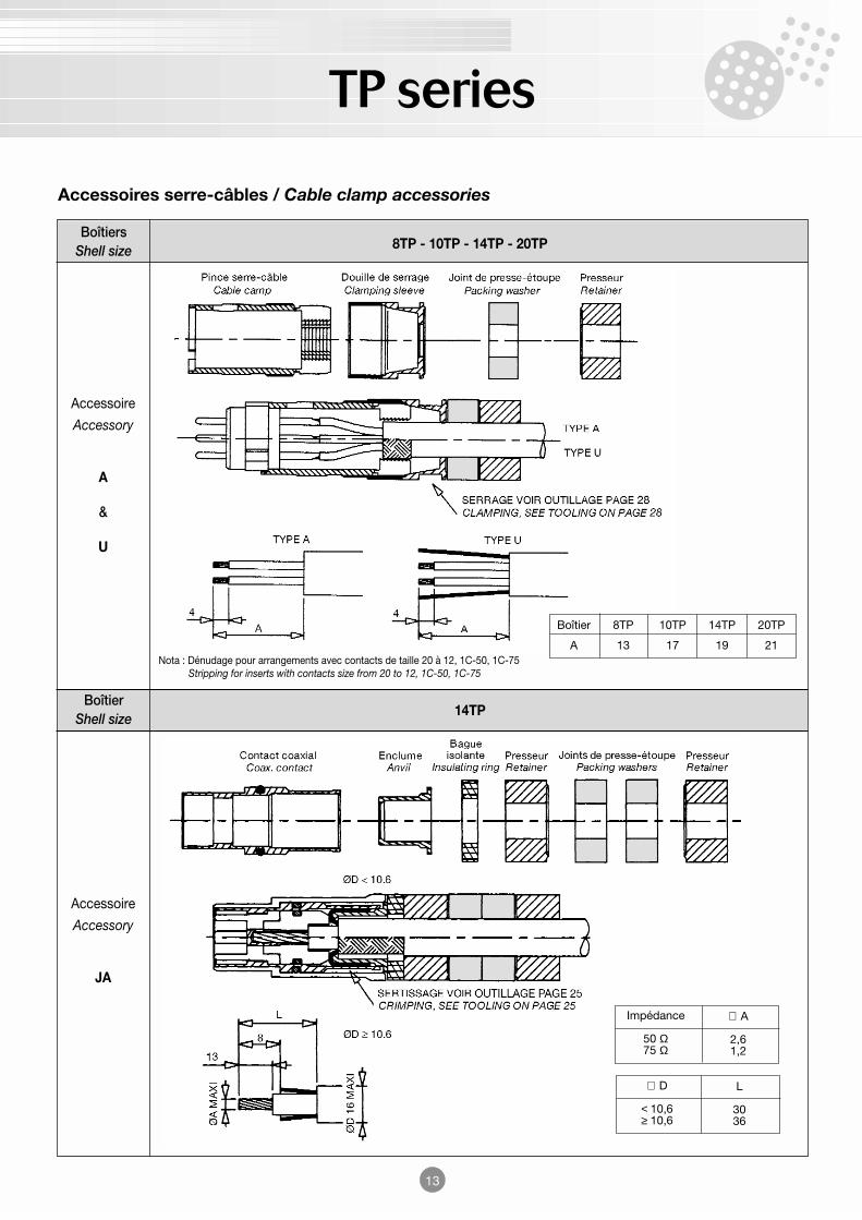
Accessoires serre-câbles / Cable clamp accessories
Boîtier14TP
Shell size
Accessoire
Accessory
A
&
U
Accessoire
Accessory
JA
Boîtiers8TP - 10TP - 14TP - 20TPShell size
Boîtier
A
8TP
13
10TP
17
14TP
19
20TP
21Nota : Dénudage pour arrangements avec contacts de taille 20 à 12, 1C-50, 1C-75
Stripping for inserts with contacts size from 20 to 12, 1C-50, 1C-75
Impédance
50 Ω75 Ω
∅ A
2,61,2
∅ D
< 10,6 ≥ 10,6
L
3036
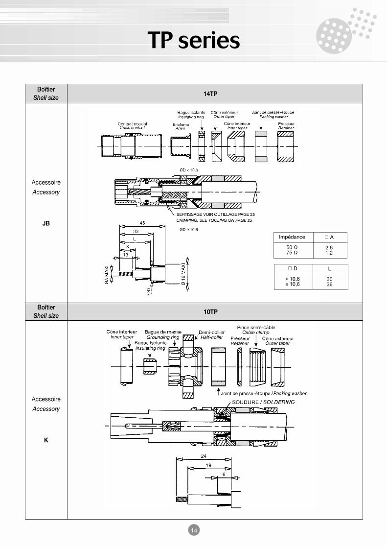
TP series
14
Boîtier10TP
Shell size
Accessoire
Accessory
JB
Accessoire
Accessory
K
Boîtier14TP
Shell size
Impédance
50 Ω75 Ω
∅ A
2,61,2
∅ D
< 10,6 ≥ 10,6
L
3036
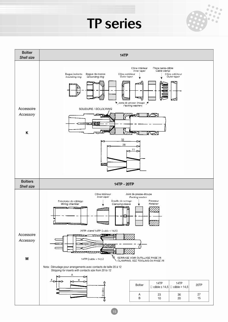
TP series
15
Boîtiers14TP - 20TP
Shell size
Accessoire
Accessory
K
Accessoire
Accessory
M
Boîtier14TP
Shell size
Boîtier
AB
14TP∅ câble ≤ 14,5
2310
14TP∅ câble > 14,5
3620
20TP
2715
Nota : Dénudage pour arrangements avec contacts de taille 20 à 12Stripping for inserts with contacts size from 20 to 12
TP series
16
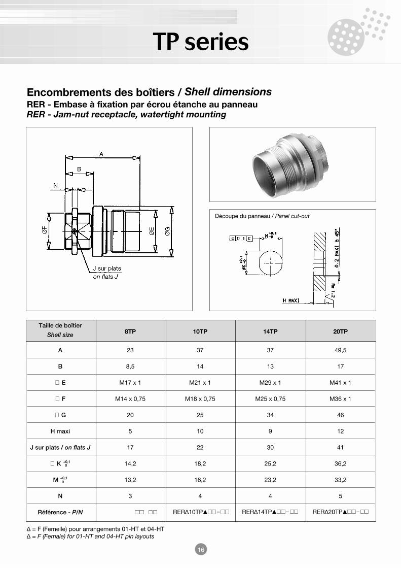
Encombrements des boîtiers / Shell dimensionsRER - Embase à fixation par écrou étanche au panneauRER - Jam-nut receptacle, watertight mounting
∆ = F (Femelle) pour arrangements 01-HT et 04-HT∆ = F (Female) for 01-HT and 04-HT pin layouts
Découpe du panneau / Panel cut-out
RER∆10TP − RER∆14TP − RER∆20TP −
0
0
Taille de boîtier8TP 10TP 14TP 20TPShell size
A 23 37 37 49,5
B 8,5 14 13 17
∅ E M17 x 1 M21 x 1 M29 x 1 M41 x 1
∅ F M14 x 0,75 M18 x 0,75 M25 x 0,75 M36 x 1
∅ G 20 25 34 46
H maxi 5 10 9 12
J sur plats / on flats J 17 22 30 41
∅ K +0,1 14,2 18,2 25,2 36,2
M +0,1 13,2 16,2 23,2 33,2
N 3 4 4 5
Référence - P/N
TP series
17
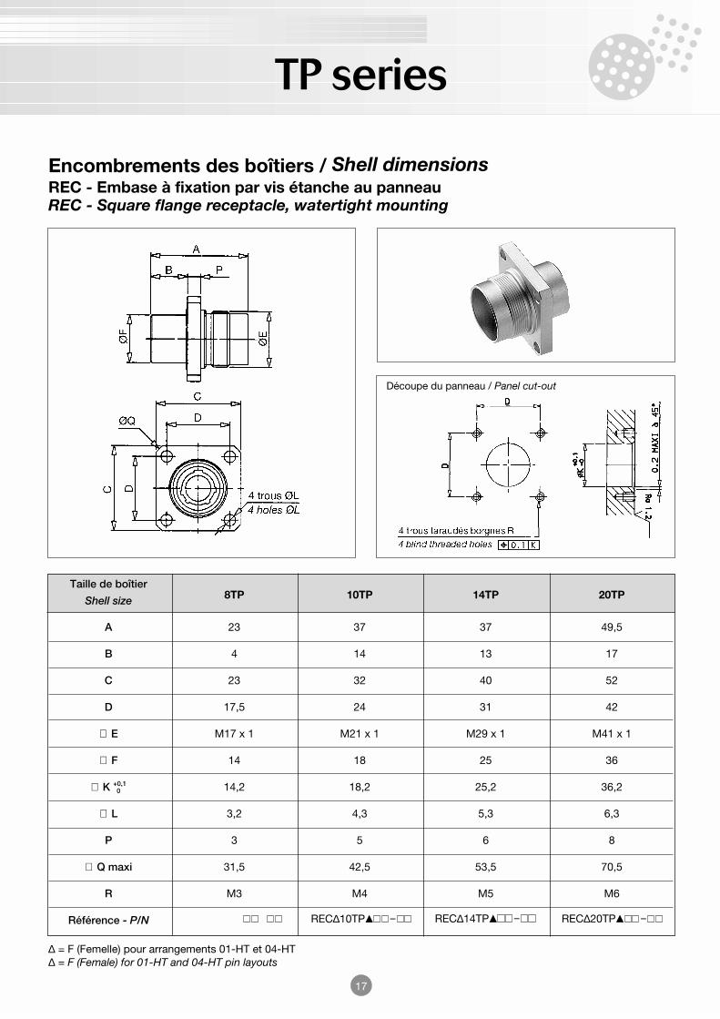
Encombrements des boîtiers / Shell dimensionsREC - Embase à fixation par vis étanche au panneauREC - Square flange receptacle, watertight mounting
∆ = F (Femelle) pour arrangements 01-HT et 04-HT∆ = F (Female) for 01-HT and 04-HT pin layouts
Découpe du panneau / Panel cut-out
REC∆10TP − REC∆14TP − REC∆20TP −
0
Taille de boîtier8TP 10TP 14TP 20TPShell size
A 23 37 37 49,5
B 4 14 13 17
C 23 32 40 52
D 17,5 24 31 42
∅ E M17 x 1 M21 x 1 M29 x 1 M41 x 1
∅ F 14 18 25 36
∅ K +0,1 14,2 18,2 25,2 36,2
∅ L 3,2 4,3 5,3 6,3
P 3 5 6 8
∅ Q maxi 31,5 42,5 53,5 70,5
R M3 M4 M5 M6
Référence - P/N
TP series
18
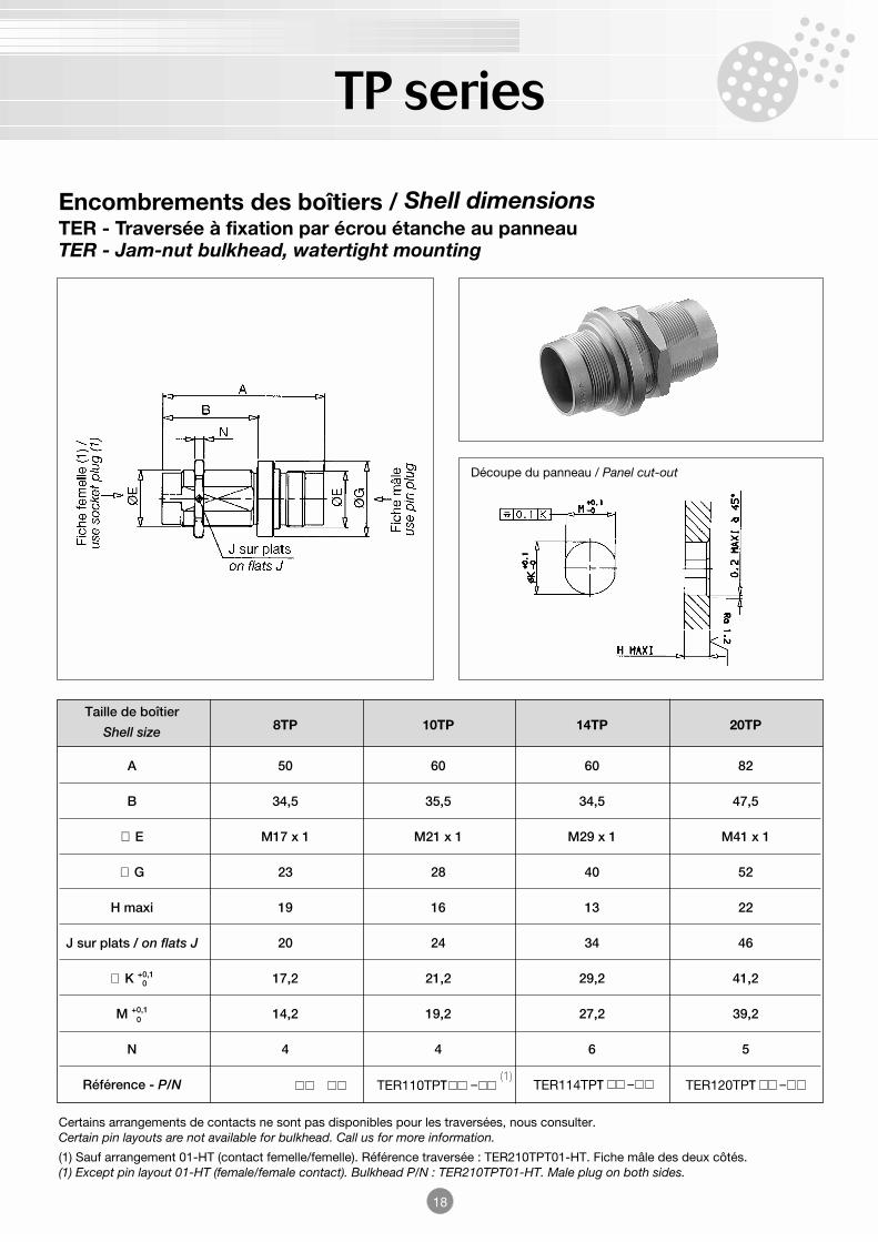
Encombrements des boîtiers / Shell dimensionsTER - Traversée à fixation par écrou étanche au panneauTER - Jam-nut bulkhead, watertight mounting
Certains arrangements de contacts ne sont pas disponibles pour les traversées, nous consulter.Certain pin layouts are not available for bulkhead. Call us for more information.
(1) Sauf arrangement 01-HT (contact femelle/femelle). Référence traversée : TER210TPT01-HT. Fiche mâle des deux côtés.(1) Except pin layout 01-HT (female/female contact). Bulkhead P/N : TER210TPT01-HT. Male plug on both sides.
Découpe du panneau / Panel cut-out
TER110TPT − TER114TPT − TER120TPT −(1)
0
0
Taille de boîtier8TP 10TP 14TP 20TPShell size
A 50 60 60 82
B 34,5 35,5 34,5 47,5
∅ E M17 x 1 M21 x 1 M29 x 1 M41 x 1
∅ G 23 28 40 52
H maxi 19 16 13 22
J sur plats / on flats J 20 24 34 46
∅ K +0,1 17,2 21,2 29,2 41,2
M +0,1 14,2 19,2 27,2 39,2
N 4 4 6 5
Référence - P/N
TP series
19
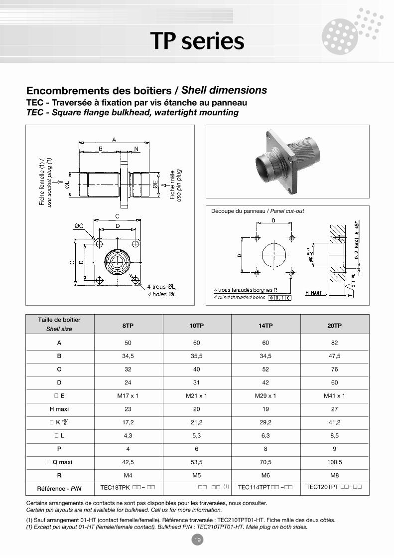
Encombrements des boîtiers / Shell dimensionsTEC - Traversée à fixation par vis étanche au panneauTEC - Square flange bulkhead, watertight mounting
Certains arrangements de contacts ne sont pas disponibles pour les traversées, nous consulter.Certain pin layouts are not available for bulkhead. Call us for more information.
(1) Sauf arrangement 01-HT (contact femelle/femelle). Référence traversée : TEC210TPT01-HT. Fiche mâle des deux côtés.(1) Except pin layout 01-HT (female/female contact). Bulkhead P/N : TEC210TPT01-HT. Male plug on both sides.
Découpe du panneau / Panel cut-out
TEC114TPT − TEC120TPT −TEC18TPK − (1)
0
Taille de boîtier8TP 10TP 14TP 20TPShell size
A 50 60 60 82
B 34,5 35,5 34,5 47,5
C 32 40 52 76
D 24 31 42 60
∅ E M17 x 1 M21 x 1 M29 x 1 M41 x 1
H maxi 23 20 19 27
∅ K +0,1 17,2 21,2 29,2 41,2
∅ L 4,3 5,3 6,3 8,5
P 4 6 8 9
∅ Q maxi 42,5 53,5 70,5 100,5
R M4 M5 M6 M8
Référence - P/N
TP series
20
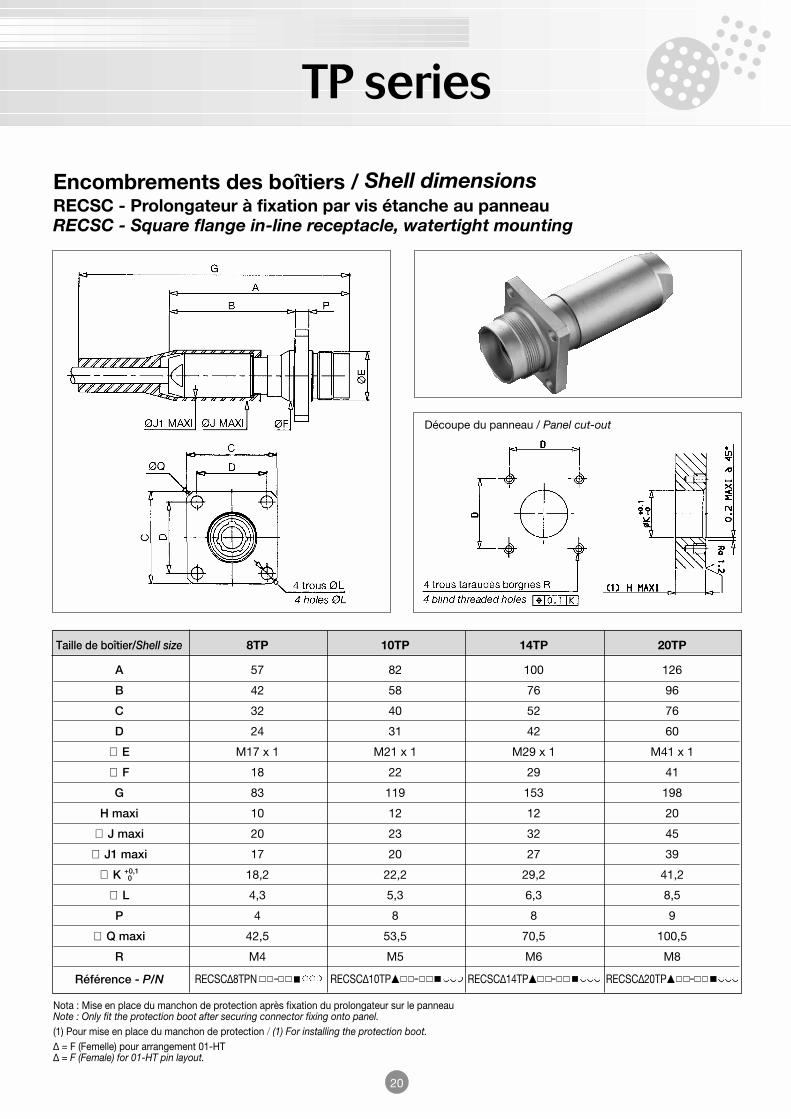
Encombrements des boîtiers / Shell dimensionsRECSC - Prolongateur à fixation par vis étanche au panneauRECSC - Square flange in-line receptacle, watertight mounting
Nota : Mise en place du manchon de protection après fixation du prolongateur sur le panneauNote : Only fit the protection boot after securing connector fixing onto panel.(1) Pour mise en place du manchon de protection / (1) For installing the protection boot.∆ = F (Femelle) pour arrangement 01-HT∆ = F (Female) for 01-HT pin layout.
Découpe du panneau / Panel cut-out
RECSC∆10TP − RECSC∆14TP − RECSC∆20TP −RECSC∆8TPN −
0
Taille de boîtier/Shell size 8TP 10TP 14TP 20TP
A 57 82 100 126
B 42 58 76 96
C 32 40 52 76
D 24 31 42 60
∅ E M17 x 1 M21 x 1 M29 x 1 M41 x 1
∅ F 18 22 29 41
G 83 119 153 198
H maxi 10 12 12 20
∅ J maxi 20 23 32 45
∅ J1 maxi 17 20 27 39
∅ K +0,1 18,2 22,2 29,2 41,2
∅ L 4,3 5,3 6,3 8,5
P 4 8 8 9
∅ Q maxi 42,5 53,5 70,5 100,5
R M4 M5 M6 M8
Référence - P/N
TP series
21
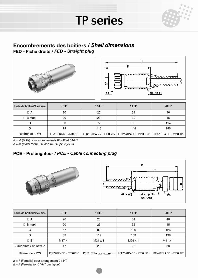
Encombrements des boîtiers / Shell dimensionsFED - Fiche droite / FED - Straight plug
∆ = M (Mâle) pour arrangements 01-HT et 04-HT∆ = M (Male) for 01-HT and 04-HT pin layouts
FED∆8TPN − FED∆10TP − FED∆14TP − FED∆20TP −
PCE - Prolongateur / PCE - Cable connecting plug
∆ = F (Femelle) pour arrangement 01-HT∆ = F (Female) for 01-HT pin layout
PCE∆8TPN − PCE∆10TP − PCE∆14TP − PCE∆20TP −
Taille de boîtier/Shell size 8TP 10TP 14TP 20TP
∅ A 20 25 34 46
∅ B maxi 20 23 32 45
C 53 72 90 114
D 79 110 144 186
Référence - P/N
Taille de boîtier/Shell size 8TP 10TP 14TP 20TP
∅ A 20 25 34 46
∅ B maxi 20 23 32 45
C 57 82 100 126
D 83 119 153 198
∅ E M17 x 1 M21 x 1 M29 x 1 M41 x 1
J sur plats / on flats J 17 20 28 38
Référence - P/N
TP series
22
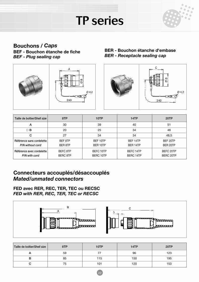
Bouchons / CapsBEF - Bouchon étanche de fiche BEF - Plug sealing cap
BER - Bouchon étanche d'embaseBER - Receptacle sealing cap
Connecteurs accouplés/désaccouplésMated/unmated connectors
FED avec RER, REC, TER, TEC ou RECSCFED with RER, REC, TER, TEC or RECSC
Taille de boîtier/Shell size 8TP 10TP 14TP 20TP
A 30 39 40 51
∅ B 20 25 34 46
C 27 34 34 48,5
Référence sans cordelette BEF 8TP BEF 10TP BEF 14TP BEF 20TPP/N without cord BER 8TP BER 10TP BER 14TP BER 20TP
Référence avec cordelette BEFC 8TP BEFC 10TP BEFC 14TP BEFC 20TPP/N with cord BERC 8TP BERC 10TP BERC 14TP BERC 20TP
Taille de boîtier/Shell size 8TP 10TP 14TP 20TP
A 59 77 96 123
B 85 115 150 195
C 75 101 120 153
TP series
∆
Sexe des contacts : M = mâle - F = femelle / Contacts : M = male - F = female
-
Arrangements des contacts, voir page 9 / Pin layouts (see page 9)
N
Isolant nylatron / Nylatron insulator
23
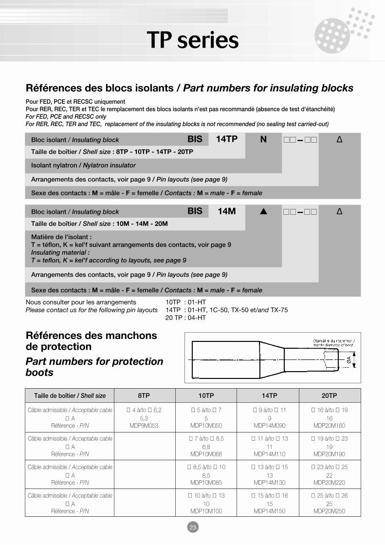
Références des blocs isolants / Part numbers for insulating blocksPour FED, PCE et RECSC uniquementPour RER, REC, TER et TEC le remplacement des blocs isolants n'est pas recommandé (absence de test d'étanchéité)For FED, PCE and RECSC onlyFor RER, REC, TER and TEC, replacement of the insulating blocks is not recommended (no sealing test carried-out)
14TPTaille de boîtier / Shell size : 8TP - 10TP - 14TP - 20TP
Bloc isolant / Insulating block BIS
∆
Sexe des contacts : M = mâle - F = femelle / Contacts : M = male - F = female
-
Arrangements des contacts, voir page 9 / Pin layouts (see page 9)
Matière de l'isolant :T = téflon, K = kel'f suivant arrangements des contacts, voir page 9Insulating material :T = teflon, K = kel'f according to layouts, see page 9
14MTaille de boîtier / Shell size : 10M - 14M - 20M
Bloc isolant / Insulating block BIS
Références des manchonsde protectionPart numbers for protectionboots
Nous consulter pour les arrangements 10TP : 01-HTPlease contact us for the following pin layouts 14TP : 01-HT, 1C-50, TX-50 et/and TX-75
20 TP : 04-HT
Taille de boîtier / Shell size 8TP 10TP 14TP 20TP
Câble admissible / Acceptable cable ∅ 4 à/to ∅ 6,2 ∅ 5 à/to ∅ 7 ∅ 9 à/to ∅ 11 ∅ 16 à/to ∅ 19∅ A 5,3 5 9 16
Référence - P/N MDP9M053 MDP10M050 MDP14M090 MDP20M160
Câble admissible / Acceptable cable ∅ 7 à/to ∅ 8,5 ∅ 11 à/to ∅ 13 ∅ 19 à/to ∅ 23∅ A 6,8 11 19
Référence - P/N MDP10M068 MDP14M110 MDP20M190
Câble admissible / Acceptable cable ∅ 8,5 à/to ∅ 10 ∅ 13 à/to ∅ 15 ∅ 23 à/to ∅ 25∅ A 8,5 13 22
Référence - P/N MDP10M085 MDP14M130 MDP20M220
Câble admissible / Acceptable cable ∅ 10 à/to ∅ 13 ∅ 15 à/to ∅ 16 ∅ 25 à/to ∅ 26∅ A 10 15 25
Référence - P/N MDP10M100 MDP14M150 MDP20M250

TP series
24
Références des joints toriquesPart numbers for O'rings
Embases REC-RERREC-RER receptacle
Fiche FEDFED plug
Prolongateur PCEPCE cable connecting plug
Traversées TEC-TERTEC-TER bulkhead
Bouchon BERBER cap
Prolongateur RECSCRECSC square flange in-linereceptacle
Taille de boîtier / Shell size 8TP 10TP 14TP 20TP
➊ Sur panneau / On panelDimension ∅ 15,1 x 1,6 ∅ 18,77 x 1,78 ∅ 26 x 2,5 ∅ 37,77 x 2,62
Référence - P/N 09-01 10-01 14-01 20-01
➋ Sur isolant / On insulatorDimension ∅ 8,1 x 1,6 ∅ 8,73 x 1,78 ∅ 15,6 x 1,78 ∅ 24 x 2
Référence - P/N 09-02 10-02 14-02 20-02
➌ Sur cône / On taper seatDimension ∅ 9,1 x 1,6 ∅ 12,42 x 1,78 ∅ 20,35 x 1,78 ∅ 30 x 2
Référence - P/N 09-03 10-03 14-03 20-03
➍ Sur panneau / On panelDimension ∅ 18,1 x 1,6 ∅ 21,95 x 1,78 ∅ 29,82 x 2,62 ∅ 42,52 x 2,62
Référence - P/N 09-04 10-04 14-04 20-04
➎ Sur panneau / On panelDimension ∅ 18,77 x 1,78 ∅ 24 x 2 ∅ 31,42 x 2,62 ∅ 42,52 x 2,62
Référence - P/N 10-01 20-02 14-05 20-04
TP series
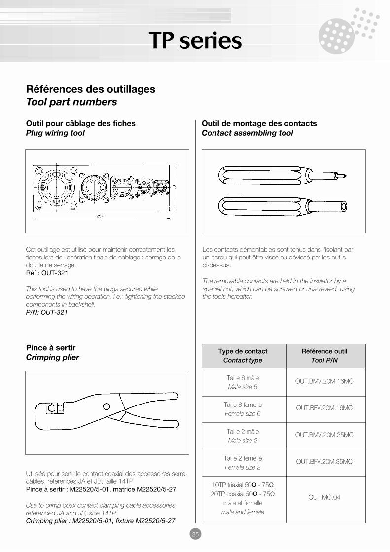
Références des outillagesTool part numbers
Outil pour câblage des fichesPlug wiring tool
Outil de montage des contactsContact assembling tool
Cet outillage est utilisé pour maintenir correctement lesfiches lors de l'opération finale de câblage : serrage de ladouille de serrage.Réf : OUT-321
This tool is used to have the plugs secured whileperforming the wiring operation, i.e.: tightening the stackedcomponents in backshell.P/N: OUT-321
Pince à sertirCrimping plier
Utilisée pour sertir le contact coaxial des accessoires serre-câbles, références JA et JB, taille 14TPPince à sertir : M22520/5-01, matrice M22520/5-27
Use to crimp coax contact clamping cable accessories,referenced JA and JB, size 14TP.Crimping plier : M22520/5-01, fixture M22520/5-27
Les contacts démontables sont tenus dans l'isolant par un écrou qui peut être vissé ou dévissé par les outilsci-dessus.
The removable contacts are held in the insulator by aspecial nut, which can be screwed or unscrewed, usingthe tools hereafter.
Type de contact Référence outilContact type Tool P/N
Taille 6 mâle OUT.BMV.20M.16MCMale size 6
Taille 6 femelle OUT.BFV.20M.16MCFemale size 6
Taille 2 mâle OUT.BMV.20M.35MCMale size 2
Taille 2 femelle OUT.BFV.20M.35MCFemale size 2
10TP triaxial 50Ω - 75Ω20TP coaxial 50Ω - 75Ω OUT.MC.04
mâle et femellemale and female
25
TP series
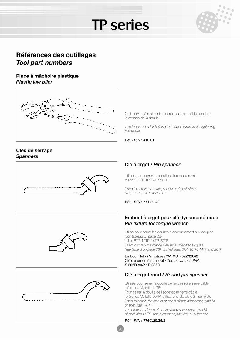
Pince à mâchoire plastiquePlastic jaw plier
Outil servant à maintenir le corps du serre-câble pendantle serrage de la douille
This tool is used for holding the cable clamp while tighteningthe sleeve
Réf - P/N : 410.01
Clé à ergot / Pin spanner
Utilisée pour serrer les douilles d'accouplementtailles 8TP-10TP-14TP-20TP
Used to screw the mating sleeves of shell sizes8TP, 10TP, 14TP and 20TP
Réf - P/N : 771.20.42
Embout à ergot pour clé dynamométriquePin fixture for torque wrench
Utilisé pour serrer les douilles d'accouplement aux couples(voir tableau B, page 28)tailles 8TP-10TP-14TP-20TPUsed to screw the mating sleeves at specified torques(see table B on page 28), of shell sizes 8TP, 10TP, 14TP and 20TP
Embout Réf / Pin fixture P/N: OUT-522/20.42Clé dynamométrique réf / Torque wrench P/N:S 305D ou/or R 305D
Clé à ergot rond / Round pin spanner
Utilisée pour serrer la douille de l'accessoire serre-câble,référence M, taille 14TPPour serrer la douille de l'accessoire serre-câble,référence M, taille 20TP, utiliser une clé plate 27 sur platsUsed to screw the sleeve of cable clamp accessory, type M,of shell size 14TPTo screw the sleeve of cable clamp accessory, type M,of shell size 20TP, use a spanner jaw with 27 clearance.
Réf - P/N : 776C.20.35.3
Références des outillagesTool part numbers
Clés de serrageSpanners
26
TP series
27
Instructions de câblage / Wiring instructions(8TP, 10TP, 14TP, 20TP accessoire serre-câble référence A et U)(8TP, 10TP, 14TP, 20TP cable clamp accessory type A and U)
1. Préparation du câble
Contrôle• Contrôler l'aspect du câble : celui-ci doit être parfaitement lisse,
rond et sans blessure.
• Vérifier : le diamètre interne du presse-étoupe doit être inférieurà celui de la gaine extérieure.
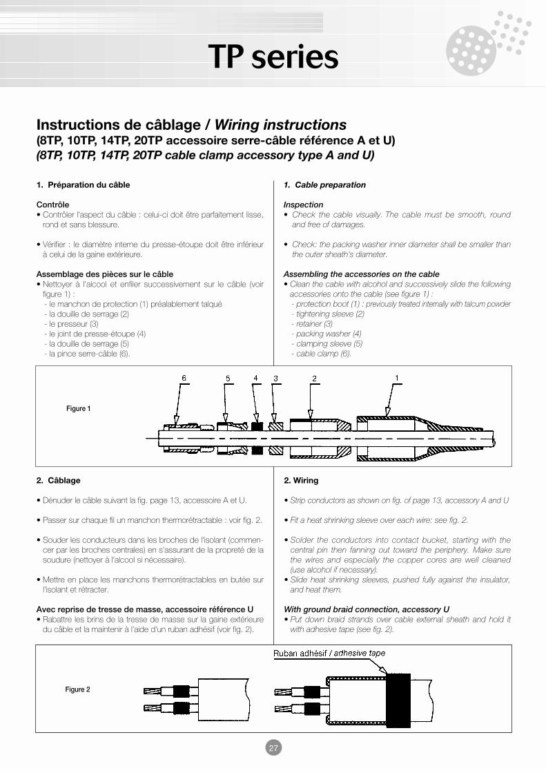
Assemblage des pièces sur le câble• Nettoyer à l'alcool et enfiler successivement sur le câble (voir
figure 1) :- le manchon de protection (1) préalablement talqué - la douille de serrage (2)- le presseur (3)- le joint de presse-étoupe (4)- la douille de serrage (5)- la pince serre-câble (6).
1. Cable preparation
Inspection• Check the cable visually. The cable must be smooth, round
and free of damages.
• Check: the packing washer inner diameter shall be smaller thanthe outer sheath's diameter.
Assembling the accessories on the cable• Clean the cable with alcohol and successively slide the following
accessories onto the cable (see figure 1) :- protection boot (1) : previously treated internally with talcum powder- tightening sleeve (2)- retainer (3)- packing washer (4)- clamping sleeve (5)- cable clamp (6).
Figure 1
2. Câblage
• Dénuder le câble suivant la fig. page 13, accessoire A et U.
• Passer sur chaque fil un manchon thermorétractable : voir fig. 2.
• Souder les conducteurs dans les broches de l'isolant (commen-cer par les broches centrales) en s'assurant de la propreté de lasoudure (nettoyer à l'alcool si nécessaire).
• Mettre en place les manchons thermorétractables en butée surl'isolant et rétracter.
Avec reprise de tresse de masse, accessoire référence U• Rabattre les brins de la tresse de masse sur la gaine extérieure
du câble et la maintenir à l'aide d'un ruban adhésif (voir fig. 2).
Figure 2
2. Wiring
• Strip conductors as shown on fig. of page 13, accessory A and U
• Fit a heat shrinking sleeve over each wire: see fig. 2.
• Solder the conductors into contact bucket, starting with thecentral pin then fanning out toward the periphery. Make surethe wires and especially the copper cores are well cleaned(use alcohol if necessary).
• Slide heat shrinking sleeves, pushed fully against the insulator,and heat them.
With ground braid connection, accessory U• Put down braid strands over cable external sheath and hold it
with adhesive tape (see fig. 2).
TP series
Tableau B / Table B
Taille de boîtier / Shell sizeCouple (mdaN)Torque (mdaN)
Douille de serrage (5) 0,4 à/to 0,4 à/to 0,4 à/to 1 à/toTightening sleeve 0,6 0,6 0,6 2
Douille de serrage (2) 0,5 à/to 1 à/to 1,5 à/to 2 à/toTightening sleeve * 2,5 3,5 4 7
Ecrou d'embase ronde 1,2 à/to 1,7 à/to 3,1 à/to 6 à/toRound receptacle nut 1,5 2 3,5 6,3
Verrou de fiche/ 0,8 0,9 à/to 1,9 à/to 4,1 à/toBouchon de fiche 1,1 2,2 4,4
Plug lock / Plug cap
Bouchon d'embase 0,9 à/to 1,2 à/to 2,5 à/to 3,5 à/toReceptacle cap 1 1,5 3 4
* Depend de la constitution du câble / Depends on the cable construction
28
Tableau A / Table A
Taille de boîtier / Shell sizeTaille de clé/emboutTorque wrench size/tip
Douille de serrage (5)11 13 18 28
Clamping sleeve
Douille de serrage (2)12 16 20 32
Tightening sleeve
3. Montage du connecteur
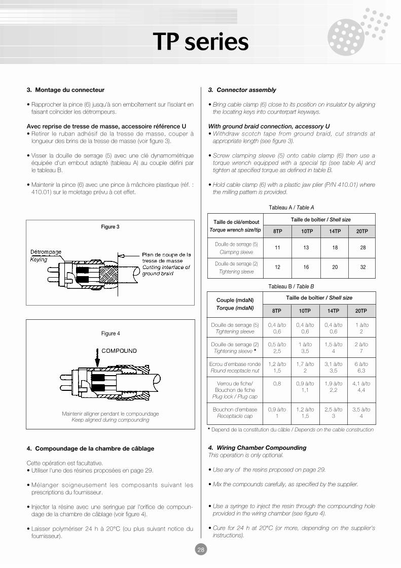
• Rapprocher la pince (6) jusqu'à son emboîtement sur l'isolant enfaisant coïncider les détrompeurs.
Avec reprise de tresse de masse, accessoire référence U• Retirer le ruban adhésif de la tresse de masse, couper à
longueur des brins de la tresse de masse (voir figure 3).
• Visser la douille de serrage (5) avec une clé dynamométriqueéquipée d'un embout adapté (tableau A) au couple défini parle tableau B.
• Maintenir la pince (6) avec une pince à mâchoire plastique (réf. :410.01) sur le moletage prévu à cet effet.
Maintenir alligner pendant le compoundageKeep aligned during compounding
Figure 4
3. Connector assembly
• Bring cable clamp (6) close to its position on insulator by aligningthe locating keys into counterpart keyways.
With ground braid connection, accessory U• Withdraw scotch tape from ground braid, cut strands at
appropriate length (see figure 3).
• Screw clamping sleeve (5) onto cable clamp (6) then use atorque wrench equipped with a special tip (see table A) andtighten at specified torque as defined in table B.
• Hold cable clamp (6) with a plastic jaw plier (P/N 410.01) wherethe milling pattern is provided.
4. Wiring Chamber CompoundingThis operation is only optional.
• Use any of the resins proposed on page 29.
• Mix the compounds carefully, as specified by the supplier.
• Use a syringe to inject the resin through the compounding holeprovided in the wiring chamber (see figure 4).
• Cure for 24 h at 20°C (or more, depending on the supplier’sinstructions).
4. Compoundage de la chambre de câblage
Cette opération est facultative.• Utiliser l'une des résines proposées en page 29.
• Mé langer soigneusement les composants suivant lesprescriptions du fournisseur.
• Injecter la résine avec une seringue par l'orifice de compoun-dage de la chambre de câblage (voir figure 4).
• Laisser polymériser 24 h à 20°C (ou plus suivant notice dufournisseur).
Figure 38TP 10TP 14TP 20TP
8TP 10TP 14TP 20TP
TP series
29
5. Assemblage final
• Graisser légèrement le joint intérieur du corps de fiche ainsi quela portée du joint sur le bloc isolant.
• Introduire l'ensemble bloc isolant/pince dans le corps de fiche :ATTENTION à bien faire coïncider les détrompeurs !
• Amener en contact le joint de presse-étoupe (4) avec la douillede serrage (5).
• Amener en contact le presseur (3) avec le joint de presse-étoupe (4).
ATTENTION : le presseur doit dépasser de 2/3 de sa hauteurau minimum par rapport au corps de fiche.
• Graisser légèrement le filetage de la douille de serrage (2).
• Visser la douille (2) avec une clé dynamométrique équipée d'unembout adapté (tableau A) au couple défini par le tableau B.Pendant cette opération la fiche sera verrouillée sur une embasefixe correspondante (réf. : OUT-321).
• Monter le manchon de protection sur la fiche (en utilisant del'alcool ou de l'huile).
Références des notices de câblages
- Accessoire serre-câble référence K : NCA 140 A 400
- Accessoire serre-câble référence M : NCA 140 A 500
- Accessoire serre-câble référence JA-JB : NCA 143 A 400
- Arrangements avec contacts taille 6 ou taille 2 : NCA 140 A 600
- Arrangements 10 TP référence TX-50 ou TX-75 et 20 TP
référence 4C-50 ou 4C-75 : NCA 140 A 700
- Arrangement 20 TP référence 04-HT : NCA 144 A 100
5. Final Assembly
• Apply a thin coat of silicone grease on the inner o'ring of theplug body as well as its seal seat on the insulator block.
• Engage the insulator block/cable clamp assembly into the plugbody: WARNING! Make sure the locating keys are lined up !
• Abut the packing washer (4) against the clamping sleeve (5).
• Abut the metal retainer (3) against the packing washer (4).
WARNING ! the retainer shall protude a minimum of twothirds of its thickness beyond connector plug shell.
• Slightly grease the thread inside the tightening sleeve (2).
• Screw the tightening sleeve (2) with a torque wrench fitted with aspecial tip (Table A) then a torque as defined in Table B. Duringthis operation, the plug shall be locked onto a correspondingfixed receptacle (P/N OUT-321).
• Install the protection boot on the plug (use alcohol or oil).
WIRING MANUALS P/Ns
- Cable fitting accessory K : NCA 140 A 400
- Cable fitting accessory M : NCA 140 A 500
- Cable fitting accessory JA.JB : NCA 143 A 400
- Arrangements with size 6/size 2 contacts : NCA 140 A 600
- Arrangements 10TP, TX-50 or TX-75 and 20TP,
4C-50 or 4C-75 : NCA 140 A 700
- Arrangement 20TP, 04-HT : NCA 144 A 100
Références des résines de compoundage de la chambre de câblageResins references to be used for coumpounding the wiring chamber
• ECCOBOND 45 : résine époxy / epoxy resinGRACE EMERSON et CUMINGS205, avenue Georges Clémenceau - 92000 NANTERRE (France)Tél : 46 14 78 40 - Fax : 47 25 40 75
• DAMIVAL : résine polyuréthane en trois / polyurethane resin in three componentsdureté shore / shore hardness D2 : 50, 85 et/and 90GEC ALSTHOM - ZI du vert galant - 15 rue Aristide Briand95310 St-OUEN l'AUMONE (France) - Tél : 30 37 40 54 - Fax : 30 37 54 01
• CAST 65 : résine polyuréthane "démontable" / polyurethane resin "removable"BARNIER9-11 rue Edouard - 26001 VALENCE (France) - Tél : 75 44 05 00 - Fax : 75 21 24 47

TP series
30
Notes