
THÈSE DOCTEUR DE L’UNIVERSITÉ DE GRENOBLEconvecs.inria.fr › doc › publications ›...
169
THÈSE Pour obtenir le grade de DOCTEUR DE L’UNIVERSITÉ DE GRENOBLE Spécialité : Informatique Arrêté ministérial : 7 Août 2006 Présentée par Rim ABID Thèse dirigée par Gwen SALAÜN et codirigée par Noël DE PALMA préparée au sein du Laboratoire d’Informatique de Grenoble (LIG) et INRIA Gre- noble Rhône-Alpes et de L’École Doctorale Mathématiques, Sciences et Technologies de l’Informa- tion, Informatique Coordination and Reconfiguration of Distributed Cloud Applications Thèse soutenue publiquement le 16/12/2015, devant le jury composé de : Mr. Christian ATTIOGBÉ Professeur à l’Université de Nantes, Rapporteur Mr. Pascal POIZAT Professeur à l’Université de Nanterre, Rapporteur Mr. Daniel HAGIMONT Professeur à l’Institut National Polytechnique de Toulouse, Examinateur Mme. Fabienne BOYER Maître de Conférences à l’Université Joseph Fourier, Examinatrice Mr. Gwen SALAÜN Maître de Conférences à Grenoble INP, Directeur de thèse Mr. Noël DE PALMA Professeur à l’Université Joseph Fourier, Co-Directeur de thèse
Transcript of THÈSE DOCTEUR DE L’UNIVERSITÉ DE GRENOBLEconvecs.inria.fr › doc › publications ›...
THÈSE
Pour obtenir le grade de
DOCTEUR DE L’UNIVERSITÉ DE GRENOBLESpécialité : Informatique
Arrêté ministérial : 7 Août 2006
Présentée par
Rim ABID
Thèse dirigée par Gwen SALAÜN
et codirigée par Noël DE PALMA
préparée au sein du Laboratoire d’Informatique de Grenoble (LIG) et INRIA Gre-
noble Rhône-Alpes
et de L’École Doctorale Mathématiques, Sciences et Technologies de l’Informa-
tion, Informatique
Coordination and Reconfiguration ofDistributed Cloud Applications
Thèse soutenue publiquement le 16/12/2015,
devant le jury composé de :
Mr. Christian ATTIOGBÉProfesseur à l’Université de Nantes, Rapporteur
Mr. Pascal POIZATProfesseur à l’Université de Nanterre, Rapporteur
Mr. Daniel HAGIMONTProfesseur à l’Institut National Polytechnique de Toulouse, Examinateur
Mme. Fabienne BOYERMaître de Conférences à l’Université Joseph Fourier, Examinatrice
Mr. Gwen SALAÜNMaître de Conférences à Grenoble INP, Directeur de thèse
Mr. Noël DE PALMAProfesseur à l’Université Joseph Fourier, Co-Directeur de thèse
AbstractCloud applications consist of a set of interconnected software components running
on multiple virtual machines. Thus, there is a need for protocols that can dynamicallyreconfigure such distributed applications. We present in the first part of this thesisa novel protocol, which can resolve dependencies in distributed cloud applications, by(dis)connecting and starting/stopping components in a particular order. The proto-col also supports virtual machine failures. The virtual machines interact through apublish-subscribe communication media and reconfigure themselves upon demand in adecentralised fashion. Designing such protocols is an error-prone task. Therefore, weinvestigated the use of formal specification languages and verification techniques, inparticular the LNT value-passing process algebra to specify the protocol and the modelchecking tools available in the CADP toolbox to verify it. Moreover, managing dis-tributed cloud applications is a challenging problem because the manual administrationis no longer realistic for these complex distributed systems. Thus, autonomic computingis a promising solution for monitoring and updating these applications automatically.This is achieved through the automation of administration functions and the use of con-trol loops, called autonomic managers. Multiple autonomic managers can be deployedin the same system and must make consistent decisions. However, using them withoutcoordination may lead to inconsistencies and error-prone situations. We propose a newapproach for coordinating stateful autonomic managers, which relies on a simple coor-dination language, new techniques for asynchronous controller synthesis and Java codegeneration. We used our approach for coordinating real-world cloud applications.
Keywords. Cloud Computing, Dynamic Reconfiguration, Distributed Applica-tions, Fault-Tolerance, Autonomic Management, Coordination, Controller Synthesis,Asynchronous Communication, Formal Verification, Process Algebra Encoding, La-belled Transition System
RésuméLes applications reparties dans le nuage sont constituées d’un ensemble de compo-
sants logiciels interconnectés et répartis sur plusieurs machines virtuelles. Cet envi-ronnement nécessite des protocoles pour reconfigurer dynamiquement ces applications.Nous présentons dans la première partie de cette thèse un nouveau protocole pour ré-soudre les dépendances dans ces applications. Ce protocole consiste à (dé) connecter etdémarrer/arrêter les composants dans un ordre spécifique. Il supporte les pannes desmachines virtuelles et les opérations de reconfiguration se terminent toujours avec suc-cès. Ces machines virtuelles interagissent à travers un «publish-subscribe support decommunication» et se reconfigurent d’une manière décentralisée. La conception de cesprotocoles étant une source d’erreurs. Alors, nous avons étudié l’utilisation des langageset techniques de verification formelles. En particulier, nous avons utilisé LNT pour spé-cifier le protocole et les outils disponibles dans la boîte à outils CADP pour le vérifier.D’autre part, la gestion des applications reparties dans le nuage est une tâche complexecar l’administration manuelle n’est plus réaliste pour ces systèmes. Nous avons proposéd’automatiser certaines fonctions d’administration en utilisant des boucles de contrôleappelées gestionnaires autonomes. Plusieurs gestionnaires peuvent être déployés pourla gestion de la même application. Cependant, leur utilisation sans coordination peutconduire à des incohérences et à des situations d’erreur. Dans la deuxième partie decette thèse, nous avons proposé une nouvelle approche pour coordonner plusieurs ges-tionnaires autonomes. Cette approche repose sur un language de coordination simple,de nouvelles techniques asynchrones pour la synthèse de contrôleur et la génération decode Java. Nous avons appliqué notre approche pour coordonner les applications repar-ties dans le nuage dans le monde réel.
Mots clés. Informatique en Nuage, Reconfiguration Dynamique, ApplicationsDistribuées, Tolérance aux Pannes, Gestion Autonome, Coordination, Synthèse deContrôleurs, Communication Asynchrone, Vérification Formelle, Encodage en Algèbrede Processus
Contents
Contents . . . . . . . . . . . . . . . . . . . . . . . . . . . . . . . . . . . . i
1 Introduction 1
1.1 Industrial Context . . . . . . . . . . . . . . . . . . . . . . . . . . . . 2
1.2 Scientific Results of the Thesis . . . . . . . . . . . . . . . . . . . . . 4
1.3 Thesis Organization . . . . . . . . . . . . . . . . . . . . . . . . . . . 7
2 Background 9
2.1 Distributed Applications . . . . . . . . . . . . . . . . . . . . . . . . 11
2.2 Cloud Computing . . . . . . . . . . . . . . . . . . . . . . . . . . . . 13
2.3 Reconfiguration of Distributed Applications . . . . . . . . . . . . 19
2.4 Autonomic Computing . . . . . . . . . . . . . . . . . . . . . . . . . 21
2.5 CADP and LOTOS NT (LNT) . . . . . . . . . . . . . . . . . . . . . 25
2.6 Conclusion . . . . . . . . . . . . . . . . . . . . . . . . . . . . . . . . 32
3 State of the Art 35
3.1 Dynamic Reconfiguration . . . . . . . . . . . . . . . . . . . . . . . 37
3.2 Coordination Models and Languages . . . . . . . . . . . . . . . . 51
3.3 Controller Synthesis Techniques . . . . . . . . . . . . . . . . . . . . 62
4 Dynamic Management Protocol for Cloud Applications 70
4.1 Reconfiguration Protocol . . . . . . . . . . . . . . . . . . . . . . . . 73
4.2 Protocol Specification and Verification . . . . . . . . . . . . . . . . 93
4.3 Experiments . . . . . . . . . . . . . . . . . . . . . . . . . . . . . . . 102
4.4 Problems Found and Corrected . . . . . . . . . . . . . . . . . . . . 104
4.5 Protocol Implementation . . . . . . . . . . . . . . . . . . . . . . . . 106
4.6 Conclusion . . . . . . . . . . . . . . . . . . . . . . . . . . . . . . . . 108
5 Asynchronous Coordination of Stateful Autonomic Managers inthe Cloud 109
5.1 Formal Models . . . . . . . . . . . . . . . . . . . . . . . . . . . . . 112
5.2 Asynchronous Synthesis Techniques . . . . . . . . . . . . . . . . . 114
5.3 Java Code Generation and Deployment . . . . . . . . . . . . . . . 122
5.4 A Multi-tier Application Supervised by Autonomic Managers . . 123
5.5 Conclusion . . . . . . . . . . . . . . . . . . . . . . . . . . . . . . . . 135
6 Conclusion 137
6.1 Achievements . . . . . . . . . . . . . . . . . . . . . . . . . . . . . . 138
6.2 Perspectives . . . . . . . . . . . . . . . . . . . . . . . . . . . . . . . 140
A Appendix: LNT process grammar 143
List of Figures
2.1 The MAPE-K reference model . . . . . . . . . . . . . . . . . . . . . 22
3.1 An example of a state machine associated to a resource driver . . 423.2 An example of an application (left) and its extended OVF descrip-
tor (right) . . . . . . . . . . . . . . . . . . . . . . . . . . . . . . . . . 443.3 An example of packages, services, and bindings described by the
Aeolus model . . . . . . . . . . . . . . . . . . . . . . . . . . . . . . 453.4 The reconfiguration steps: the prepare and commit phases . . . . 473.5 The coordination medium when: using a data driven coordina-
tion language (left); using an event-driven coordination language(right) . . . . . . . . . . . . . . . . . . . . . . . . . . . . . . . . . . . 52
3.6 Multi-agent architecture for establishing an energy consumptionpolicy . . . . . . . . . . . . . . . . . . . . . . . . . . . . . . . . . . . 59
3.7 Control of a decentralized reactive system, regarded as subsys-tems, through local controllers on each subsystem . . . . . . . . . 67
4.1 Example of an application model (before binding ports) . . . . . . 744.2 Example of an application model (after binding ports) . . . . . . . 754.3 Protocol participants: reconfiguration manager, VMs, and
publish-subscribe messaging system . . . . . . . . . . . . . . . . . 774.4 The agent behaviour when adding a new component: (i) without
imports; (ii) with, at least, a mandatory import; and (iii) with,only optional imports . . . . . . . . . . . . . . . . . . . . . . . . . . 79
4.5 Instantiating VM1 then Instantiating VM2 . . . . . . . . . . . . . . 824.6 Instantiating VM2 then Instantiating VM1 . . . . . . . . . . . . . . 834.7 The agent behavior when removing a component . . . . . . . . . 854.8 The agent behavior when stopping a component . . . . . . . . . . 86
4.9 The RM behavior when detecting a VM failure . . . . . . . . . . . 874.10 The PS behavior when receiving an alert failure message . . . . . 884.11 Example of a running application composed of connected and
started components . . . . . . . . . . . . . . . . . . . . . . . . . . . 894.12 The participants behavior when removing the Tomcat component 904.13 The participants behavior when adding the Tomcat component . 924.14 The participants behavior when detecting the VM3 failure . . . . 934.15 Tool support . . . . . . . . . . . . . . . . . . . . . . . . . . . . . . . 954.16 Experimental results when increasing the number of VMs (left)
start-up scenario without failure, (right) start-up and destructionscenario without failure . . . . . . . . . . . . . . . . . . . . . . . . 104
5.1 Overview of our approach . . . . . . . . . . . . . . . . . . . . . . . 1125.2 Example of a manager modelled as an LTS (left), and the LNT
process encoding the initial state (right) . . . . . . . . . . . . . . . 1165.3 Example of coordination requirements encoded into an LNT pro-
cess . . . . . . . . . . . . . . . . . . . . . . . . . . . . . . . . . . . . 1185.4 Exchange of messages between the coordination expression and
the managers . . . . . . . . . . . . . . . . . . . . . . . . . . . . . . 1215.5 A multi-tier application . . . . . . . . . . . . . . . . . . . . . . . . 1245.6 (left) The architecture of the self-sizing manager, (right) the archi-
tecture of the self-repair manager . . . . . . . . . . . . . . . . . . . 1255.7 (left) Self-repair manager LTS, (middle) Self-sizing manager LTS,
(right) Application manager LTS . . . . . . . . . . . . . . . . . . . 1255.8 Excerpt of the controller LTS for the running example . . . . . . . 1315.9 Tomcat and MySQL failure/overload in a coordinated environment1345.10 Number of reconfiguration operations with/without coordina-
tion and number of undesired operations avoided by coordination 135
List of Tables
2.1 Cloud Computing Definitions . . . . . . . . . . . . . . . . . . . . . 142.2 Coordination Definitions . . . . . . . . . . . . . . . . . . . . . . . . 23
3.1 Comparison between the languages and approaches used for dy-namic reconfiguration . . . . . . . . . . . . . . . . . . . . . . . . . 50
3.2 Comparison between controller synthesis techniques . . . . . . . 68
4.1 Experimental results (with failures) . . . . . . . . . . . . . . . . . 105
5.1 Experimental results: LTSs size and synthesis time . . . . . . . . . 133
AcronymsA
ACP Algebra of Communicating Processes
ADL Architecture Description Language
B
BCG Binary Coded Graphs
C
CADP Construction and Analysis of Distributed Processes
CONVECS Construction of Verified Concurrent Systems
D
DADL Distributed Application Description Language
DCS Discrete Controller Synthesis
DES Discrete Event System
DSL Domain Specific Language
E
ERODS Efficient and Robust Distributed Systems
F
FSN Fonds National pour la Société Numérique
I
IaaS Infrastructure as a Service
IT Information Technology
J
JVM Java Virtual Machine
L
LNT LOTOS NT
LOTOS Language Of Temporal Ordering Specification
LTL Linear Temporal Logic
LTS Labelled Transition System
M
MAPE-K Monitor Analyse Plan Execute - Knowledge
MCL Model Checking Language
N
NIST National Institute of Standards and Technology
O
OVF Open Virtualization Format
P
PaaS Platform as a Service
PS Publish-Subscribe Messaging System
Q
QoS Quality of Service
R
RM Reconfiguration Manager
S
SaaS Software as a Service
SLA Service Level Agreements
SmartFrog Smart Framework for Object Group
SVL Scripting Language for Compositional Verification
V
VAMP Virtual Applications Management Platform
VM Virtual Machine
1Introduction
" Work is the only thing that gives substance to life. "
Albert Einstein
Contents
1.1 Industrial Context . . . . . . . . . . . . . . . . . . . . . . . . . . 2
1.1.1 Presentation of the OpenCloudware Project . . . . . . . 2
1.1.2 Project Expectations . . . . . . . . . . . . . . . . . . . . 3
1.1.3 Position in the OpenClouware Project . . . . . . . . . . 3
1.2 Scientific Results of the Thesis . . . . . . . . . . . . . . . . . . . 4
1.2.1 Motivations . . . . . . . . . . . . . . . . . . . . . . . . . 4
1.2.2 Objectives and Main Contributions . . . . . . . . . . . . 6
1.3 Thesis Organization . . . . . . . . . . . . . . . . . . . . . . . . . 7
1.1. Industrial Context 2
THis Ph.D. thesis research is part of the OpenCloudware project 1. We presentin this chapter the OpenCloudware project, a brief survey of its expecta-
tions, the thesis positioning in the project and, in a second part, we introducethe problem statement, the main contributions, and the thesis organization.
1.1 Industrial Context
1.1.1 Presentation of the OpenCloudware Project
The OpenCloudware project is a collaborative research project. It is fundedby the French authorities – specifically through the Fonds National pour la So-ciété Numérique (FSN) and started in January 2012 for a duration of three yearsand nine months. The project, known for its original approaches and technicalinnovations, is endorsed by Pôles de compétitivité Minalogic 2, Systematic 3, andSCS 4.
The project members include 18 partners composed of academic partners(Armines, Inria, IRIT – INP Toulouse, Télécom Paris Tech, Télécom Saint-Etienne, Université Joseph Fourier, and Université de Savoie – LISTIC), indus-try leaders and innovative technology start-ups (France Telecom, ActiveEon,Bull, eNovance, eXo Platform, Peergreen, Linagora, Thales Communications,Thales Services, and UShareSoft), and a world-renowned open source commu-nity (OW2).
Each partner of the OpenCloudware project participated with one or morecontributions to the project solution and had its own expectations.
1. http://www.opencloudware.org2. http://www.minalogic.org/3. http://www.systematic-paris-region.org/4. http://www.pole-scs.org/
1.1. Industrial Context 3
1.1.2 Project Expectations
The openCloudWare project intends to build an open software engineeringplatform. This platform will be used for the development of distributed appli-cations, e.g., multi-tier applications such as JavaEE, which need to be deployedon multiple Cloud infrastructures. The project results will be summarized as aset of software components that allow the cloud users to model, develop, andbuild their applications in order to obtain a multi-IaaS compliant PaaS plat-form for the deployment, orchestration, performance testing, self-management,and provisioning of the applications. These components have been made avail-able, in October 2015, as open source components through the OW2 open sourcecommunity.
It is worth noting that the OpenCloudware project addresses multiple tech-nological issues and challenges that we summarize here:
— providing a complete modeling, so-called end-to-end (retro-) modeling,starting from the applications and achieving both PaaS and IaaS serviceson the platform of cloud computing;
— automating the orchestration of the modules that compose the platformto manage the applications life-cycle in a virtual context;
— reacting to the dynamic changes that can occur in a cloud PaaS appli-cation by means of autonomic management, which takes into accountelasticity constraints, energy optimization, and also the reliability of thedeployed services;
— providing an interoperable execution of multi-cloud IaaS interfaces;— optimizing the services performance and cost by taking globally coherent
decisions;— ensuring the security in terms of application isolation, encryption, and
management.
1.1.3 Position in the OpenClouware Project
The OpenCloudware project contains six technical and scientific subprojects(SP1, 2, 3, 4, 5, and 7), a validation subproject SP6, and a subproject dedicated
1.2. Scientific Results of the Thesis 4
to dissemination SP8.Within this project, the CONVECS and ERODS teams, in which this thesis wasprepared, participate essentially in SP1 and SP3. The major goal of SP1 is to de-fine an overall architecture, a model for distributed applications, services of thePaaS platform, and capacities of the IaaS infrastructures. The major goal of SP3is to develop generic components and tools for the deployment, the automatedorchestration, and the performance testing. SP3 also aims at administrating thePaaS platform, particularly the autonomic management of dynamic changes indistributed applications.
The position of this thesis in the OpenCloudware project has responded tothe need for the management of dynamic models and the autonomic admin-istration of applications. It also includes the need to formalize the dynamicaspects of these models in order to experiment the administrative functions,to formally specify management protocols for cloud applications, and to ver-ify them using the model-checking and verification tools developed within theCONVECS team.
1.2 Scientific Results of the Thesis
1.2.1 Motivations
During the last few years, the IT operating costs have risen considerably ina continuous way. Therefore, companies have, increasingly, outsourced their ITservices and have been reluctant to entrust them to specialists, such as cloudproviders. Thus, cloud computing has been an active research topic. In termsof market adoption, it leverages hosting platforms based on virtualization andprovides resources and software applications as services over the network.Cloud computing allows, on the one hand, service providers to develop andthen sell distributed applications, composed of virtual machines and hostinginterconnected software components, worldwide without having to invest up-front in expensive IT infrastructures. On the other hand, it allows the users toaccess services, to benefit from them through a Web browser, and to pay only
1.2. Scientific Results of the Thesis 5
for the services used. As a result, the software systems transform from central-ized to distributed and from static to dynamic.The cloud users need to (re) configure and monitor applications during theirtime life for elasticity or maintenance purposes. Therefore, after the deploy-ment of these applications, some reconfiguration operations are required for set-ting up new virtual machines, replicating some of them, destroying or addingvirtual machines, handling VM failures, and adding or removing componentshosted on a VM. These tasks are required to react to changes (such as the occur-rence of a failure), to include new requirements, or to fulfill the users expecta-tions. Some of these tasks are executed in parallel, which involves a high degreeof parallelism and complicates their correct execution. Moreover, in the contextof the OpenCloudware project, architectural invariants (e.g., started compo-nents cannot be connected to stopped components) must be preserved whenthe reconfiguration operations are executed.Several research studies and protocols have been proposed to support the self-deployment of cloud applications. These protocols manage static applications,which are composed of a set of virtual machines, ports, components, and con-nections between the components where the number of these elements and theinvolved connections are known before the application execution. However,cloud users need protocols that permit to deploy such applications and thatare also able to modify these applications during their execution. The existingprotocols, e.g., [60, 62, 126] do not support the applications that require to bechanged after the deployment phase.
Moreover, today, the requirements of the cloud users are continuously evolv-ing, which leads to the increase of the complexity of the cloud applicationsand their management becomes a crucial feature. Therefore, the management ofthese applications is a challenging problem for administrators. The manual ad-ministration is no longer realistic for these complex distributed systems and en-vironments. Thus, autonomic computing has become a promising solution forobserving, monitoring, and updating these applications automatically. Theseactions are achieved through the automation of administrative functions andthe use of control loops, called autonomic managers. However, available man-agers can be designed to address the requirements of a particular applicationdomain without coordination. This may lead the whole system to the perfor-
1.2. Scientific Results of the Thesis 6
mance degradation and some undesired situation (e.g., adding two new serverswhereas one was enough as a result of a server failure). Therefore, the coordi-nation of multiple control loops managing the same application, particularlydistributed cloud applications, is a central issue that appears as a real need inthe context of the OpenCloudware project.
1.2.2 Objectives and Main Contributions
One of the goals of the OpenCloudware project is to dynamically reconfigurecloud applications composed of interconnected software components runningon different virtual machines in an automatic way. However, achieving dynam-ically the reconfiguration process is a complicated task. First, when reconfigur-ing a distributed application, it is necessary to execute the reconfiguration oper-ations, while preserving architectural invariants (e.g., a started component can-not be connected to a stopped one) at each step of the application runtime, par-ticularly when components need to be stopped in sequence across several VMs.Another difficulty with the dynamic reconfiguration of distributed applicationsis that these applications can be faced with a set of virtual machines or compo-nents failures that may occur during the reconfiguration process. Therefore, inthis thesis, we take into consideration the fault tolerance, meaning that the re-configuration process must always terminate successfully even in the presenceof a finite number of failures. Another issue, which arises when automatingthe reconfiguration process, is the necessity to take coherent decisions, whichshould not lead the system to inconsistent situations.
To automatically bring the deployment and (re)configuration tasks in dis-tributed applications, this thesis contributes with a novel, robust, and fault-tolerant protocol, which enables to execute dynamically reconfiguration tasks,e.g., instantiate and destroy virtual machines and supports virtual machinefailures. Moreover, the protocol is decentralized in the sense that all virtualmachines communicate information (e.g., binding details, component state)through a publish-subscribe communication media. The protocol also allowsto start/stop the disconnected components in a particular order for preservingthe application consistency (i.e., architectural invariants) at each step of its ex-
1.3. Thesis Organization 7
ecution. This first contribution is assessed through the use of formal methodsand verification techniques of the CADP toolbox. Concretely, the evaluation isperformed by the specification and the verification of multiple properties ondifferent reconfiguration scenarios and a large set of case studies, ranging fromsimple ones to other containing several VMs and components.
A second contribution of this thesis is the integration of new controller syn-thesis techniques in the automatization of administration functions in order toreduce the manual execution of reconfiguration tasks. The automatization pro-cess is performed through the use of control loops, called autonomic managers.An autonomic manager observes the application execution, ensures a contin-uous monitoring, and reacts to events and changes by automatically reconfig-uring the applications. This contribution proposes new asynchronous synthesistechniques in order to coordinate several managers and allow them to take co-herent decisions globally. The generation of the controller is based on reactionrules and regular expressions used to specify the coordination requirements andinteraction constraints. This contribution relies on formal techniques, in partic-ular we use the verification techniques available in the CADP toolbox for gen-erating the controller, validating it, and ensuring that all managers globally sat-isfy the objectives. We also propose Java code generation techniques that allowto deploy the generated controller for real applications in the cloud.
1.3 Thesis Organization
We have started this dissertation with the industrial context of the thesis, asummary of the scientific motivations, and the main contributions. The remain-der of this dissertation is structured as follows:
— Chapter 2 In this chapter, we present a description of some terms (e.g.,distributed applications, cloud computing, dynamic reconfiguration, au-tonomic computing, coordination, formal methods) used in the resultspresented in the subsequent chapters.
— Chapter 3 In this chapter, we present a literature review on dynamicreconfiguration, coordination languages, and controller synthesis tech-niques.
1.3. Thesis Organization 8
— Chapter 4 In this chapter, we present a novel dynamic protocol for re-configuring distributed cloud applications. The protocol is specified andverified using formal techniques and tools to ensure that it preserves im-portant architectural invariants (e.g., a started component cannot be con-nected to a stopped component) and satisfies certain properties (e.g., eachVM failure is followed by a new creation of that VM).
— Chapter 5 In this chapter, we describe new asynchronous controller syn-thesis techniques allowing the generation of a centralized controller,which aims at coordinating several autonomic managers in the cloud.These techniques cover the whole development process from the expres-sion of coordination requirements to the deployment of the controller forcoordinating real applications.
— Chapter 6 In this chapter, we conclude and present some perspectives forfurther research.
Publications
Some results of this thesis have been published in the following papers:
— R. Abid, G. Salaün, F. Bongiovanni, N. De Palma, Verification of aDynamic Management Protocol for Cloud Applications, in: Proc. ofATVA’13, Vol. 8172 of LNCS, Springer, 2013, pp. 178–192.
— R. Abid, G. Salaün, N. De Palma, S.M. Kare, Asynchronous Coordina-tion of Stateful Autonomic Managers in the Cloud, in: Proc. of FACS’15,LNCS, Springer, 2015, To appear.

2Background
" The point of philosophy is to start with something so simple as not to seem worthstating, and to end with something so paradoxical that no one will believe it. "
Bertrand Russell
Contents
2.1 Distributed Applications . . . . . . . . . . . . . . . . . . . . . . 11
2.1.1 Characteristics of Distributed Applications . . . . . . . 11
2.1.2 Purposes of Distributed Applications . . . . . . . . . . 12
2.2 Cloud Computing . . . . . . . . . . . . . . . . . . . . . . . . . . 13
2.2.1 Cloud Computing Definition . . . . . . . . . . . . . . . 13
2.2.2 Cloud Characteristics . . . . . . . . . . . . . . . . . . . . 16
2.2.3 Cloud Service Models . . . . . . . . . . . . . . . . . . . 17
2.2.4 Cloud Deployment Models . . . . . . . . . . . . . . . . 18
10
2.3 Reconfiguration of Distributed Applications . . . . . . . . . . . 19
2.4 Autonomic Computing . . . . . . . . . . . . . . . . . . . . . . . 21
2.4.1 Autonomic Manager Definition and Implementation . 22
2.4.2 Coordinating Multiple Autonomic Managers . . . . . . 23
2.5 CADP and LOTOS NT (LNT) . . . . . . . . . . . . . . . . . . . . 25
2.5.1 Formal Methods . . . . . . . . . . . . . . . . . . . . . . 25
2.5.2 CADP toolbox . . . . . . . . . . . . . . . . . . . . . . . . 27
2.5.3 LOTOS NT (LNT) . . . . . . . . . . . . . . . . . . . . . . 31
2.6 Conclusion . . . . . . . . . . . . . . . . . . . . . . . . . . . . . . 32
2.1. Distributed Applications 11
IN this chapter, we introduce techniques and definitions of some terms usedin the results presented in the subsequent chapters. First, we give defini-
tions and general characteristics of distributed applications, cloud computing,dynamic reconfiguration, autonomic computing, and coordination. In a secondstep, we introduce existing formal techniques and tools that have been em-ployed to achieve the objectives and contributions of the thesis.
2.1 Distributed Applications
Since the appearance of computers in the middle of the 20th century, the ap-plication complexity has been continuously and exponentially growing. In fact,applications are more sophisticated and able to respond to new users needs andrequirements in terms of Quality of Service (QoS), availability, performance,and also productivity [83, 122]. These applications often consist of a set of in-terconnected software components that interact together, where configurationattributes characterize each component. All components are hosted on differentpossibly remote machines.
2.1.1 Characteristics of Distributed Applications
Various types of distributed applications have been developed and used indifferent domains. All of them are characterized by the following importantfeatures [118, 18, 37, 73]: (i) the composition of several entities, which are dis-tributed across multiple machines or servers geographically distant; (ii) the de-ployment of that entities on heterogeneous servers; (iii) an important diversityof resources used for the decision-making process and for the reduction of thereaction time; and (iv) the ability to take into account dynamic modificationsand to inter-operate with other applications deployed in the same environment.These features are fundamental to the understanding of this type of applica-tions. Furthermore, they are accompanied by a set of issues, e.g., a low auton-omy, a high administration cost, and a resource under-utilization.First, the lack of autonomy in the administration of a distributed applicationhas a significant impact on limiting its adaptation to the changes that may oc-
2.1. Distributed Applications 12
cur in its environment. Actually, the installation phases or application updatesrequire, sometimes, the intervention of an expert to examine the machines usedfor the application deployment.Second, each distributed application also requires the intervention of adminis-trators, who need diverse knowledge bases of hardware, middleware, and alsoof the application itself, in order to configure it properly. Thus, the administra-tion of the distributed applications has become a critical task in terms of timeand cost. According to J. Moad [109], A. Eastwood [56], and L. Erlikh [58], thecost of software maintenance and evolution management represents between75% and 90% of the total budget spent on information technology.Moreover, taking into account constraints on reliability, security, and quality ofservice requires that each application is deployed on a set of machines ded-icated to it, which leads to a potential under-utilization of the same hardwareresources. Referring to a recent study conducted by Kelton Research [120], com-missioned in association with the Alliance to Save Energy, the world’s largest ITdepartments have 15% of servers that are not doing anything useful accordingto 72% of the server managers.
In this context, the OpenCloudware project aims at building an open soft-ware platform. The platform will be used for the collaborative developmentof distributed applications that need to be deployed on multiple Cloud infras-tructures. Modifications in distributed applications composed of interconnectedcomponents play a significant motivation of this work, with a focus particularlyset on the dynamic reconfiguration and how reconfiguration operations can beexecuted.
2.1.2 Purposes of Distributed Applications
Distributed applications are composed of interconnected software compo-nents that interact together to access services and exchange information. To en-sure interactions between the different components, five important purposeshave to be guaranteed [51]: (i) the resource sharing, which presents the abilityto easily share data, hardware, and software resources among different userswith access control; (ii) the scalability, which presents the ability to provide a
2.2. Cloud Computing 13
higher load, especially when adding users, transactions, or data volume; (iii) thefault-tolerance, which presents the capacity to minimize the loss of resourceswhen faults happen, while interactions and operations between componentsmust still stand, even when other components have failed; (iv) the dynamicity,which presents the ability to, easily, make the system extensible by integratingor removing components during the application life cycle in order to meet newusers’ requirements; and finally (v), the transparency, which presents the abilityto duplicate the resources invisibly and ensure seamless access to both local andremote resources.
These purposes, especially resource sharing, fault-tolerance, and opennessplay a fundamental role in this thesis. As stated before, one of the major contri-butions of this thesis is designing a fault-tolerant protocol, which dynamicallyreconfigures distributed applications by adding or removing components to in-clude new users’ requirements.
2.2 Cloud Computing
2.2.1 Cloud Computing Definition
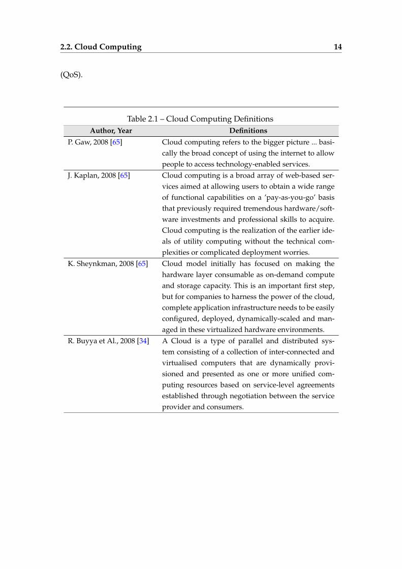
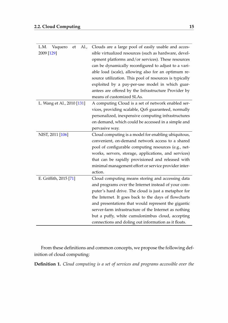
There exist different definitions and concepts that aim at describing cloudcomputing [34, 45, 129, 140, 131, 65, 106, 71]. We present in this chapter some no-tions of cloud computing proposed in the literature (Table 2.2.1) to define a com-mon denominator for all these concepts. In [65], J. Geelan introduces some cloudcomputing definitions, which are proposed by several experts, e.g., P. Gaw, J.Kaplan, K. Sheynkman. According to K. Sheynkman, the deployment, the opti-mization of energy consumption, and the provisioning of resources on-demandare the main goal of cloud computing. Other experts, such as L.M. Vaquero [129]and the National Institute of Standards and Technology (NIST) [106], considerthe cloud as a convenient model, which enables sharing virtualized resources,on-demand, for a large pool of users who pay only what they consume. R.Buyya [34] and L. Wang [131] describe the cloud as a set of networks enabledservices, which focus on service-level agreements (SLA) and quality of service
2.2. Cloud Computing 14
(QoS).
Table 2.1 – Cloud Computing DefinitionsAuthor, Year Definitions
P. Gaw, 2008 [65] Cloud computing refers to the bigger picture ... basi-cally the broad concept of using the internet to allowpeople to access technology-enabled services.
J. Kaplan, 2008 [65] Cloud computing is a broad array of web-based ser-vices aimed at allowing users to obtain a wide rangeof functional capabilities on a ’pay-as-you-go’ basisthat previously required tremendous hardware/soft-ware investments and professional skills to acquire.Cloud computing is the realization of the earlier ide-als of utility computing without the technical com-plexities or complicated deployment worries.
K. Sheynkman, 2008 [65] Cloud model initially has focused on making thehardware layer consumable as on-demand computeand storage capacity. This is an important first step,but for companies to harness the power of the cloud,complete application infrastructure needs to be easilyconfigured, deployed, dynamically-scaled and man-aged in these virtualized hardware environments.
R. Buyya et Al., 2008 [34] A Cloud is a type of parallel and distributed sys-tem consisting of a collection of inter-connected andvirtualised computers that are dynamically provi-sioned and presented as one or more unified com-puting resources based on service-level agreementsestablished through negotiation between the serviceprovider and consumers.
2.2. Cloud Computing 15
L.M. Vaquero et Al.,2009 [129]
Clouds are a large pool of easily usable and acces-sible virtualized resources (such as hardware, devel-opment platforms and/or services). These resourcescan be dynamically reconfigured to adjust to a vari-able load (scale), allowing also for an optimum re-source utilization. This pool of resources is typicallyexploited by a pay-per-use model in which guar-antees are offered by the Infrastructure Provider bymeans of customized SLAs.
L. Wang et Al., 2010 [131] A computing Cloud is a set of network enabled ser-vices, providing scalable, QoS guaranteed, normallypersonalized, inexpensive computing infrastructureson demand, which could be accessed in a simple andpervasive way.
NIST, 2011 [106] Cloud computing is a model for enabling ubiquitous,convenient, on-demand network access to a sharedpool of configurable computing resources (e.g., net-works, servers, storage, applications, and services)that can be rapidly provisioned and released withminimal management effort or service provider inter-action.
E. Griffith, 2015 [71] Cloud computing means storing and accessing dataand programs over the Internet instead of your com-puter’s hard drive. The cloud is just a metaphor forthe Internet. It goes back to the days of flowchartsand presentations that would represent the giganticserver-farm infrastructure of the Internet as nothingbut a puffy, white cumulonimbus cloud, acceptingconnections and doling out information as it floats.
From these definitions and common concepts, we propose the following def-inition of cloud computing:
Definition 1. Cloud computing is a set of services and programs accessible over the
2.2. Cloud Computing 16
networks from anywhere, at any time, and on various media. It enables users to purchasevirtualized resources on-demand, pay only what they consume, and optimize the energyconsumption.
2.2.2 Cloud Characteristics
According to the NIST company [106], cloud computing is composed of fiveessential characteristics, which are: (1) on demand self-services refers to the abil-ity to consume services (e.g., email, applications, network storage), as needed,without requiring human interaction with the service provider. The consumerpays only what he uses, i.e., only for the amount of the resources he uses. (2) Re-source pooling means that computer resources are grouped into a large pool,which allows to serve all the consumers. These resources are dynamically allo-cated according to the demand of users. The consumer has no control or knowl-edge over the resources providers and locations. (3) Rapid elasticity refers tothe cloud capabilities that can be elastically released to scale outward and in-ward about the request. For the consumer, the required resources must be ap-propriated in any quantity and at any time. (4) Broad network access allows theavailability of cloud services over the network and their accessibility throughstandard mechanisms, e.g., mobile phones, smartphone. (5) Measured servicesmean that cloud systems automatically control, optimize, and monitor the useof resources by using the model "pay only what you consume" which providesthe transparency for both service provider and service consumer.
These characteristics explain the need for protocols that are not limited tothe self-deployment issues where the application model (virtual machines, com-ponents, ports, and bindings between components) to be deployed exists andguides the configuration process. The cloud users need protocols that work, asautomatically as possible, in all the situations where changes have to be appliedon to a running application. The protocols should dynamically reconfigure theapplications. The protocol developed in this thesis dynamically reconfiguresand manages cloud applications, which consist of interconnected software com-ponents. Every component exports services that it is willing to provide andimports required services. Therefore, each service may be needed by several
2.2. Cloud Computing 17
components and can thus be accessible to several imports.
2.2.3 Cloud Service Models
There are different cloud service delivery models, which are provided to thecloud users and divided into the three main following Layers [106]:
— Infrastructure as a Service (IaaS) is the basis layer, which contains all theresources provided to the cloud consumers. IaaS cloud providers offerthese resources (e.g., CPU, memory, network) on-demand to allow theconsumers to deploy and run their applications. Examples of typical IaaSproviders include Amazon EC2 1, Windows Azure 2, Google ComputeEngine 3, and Rackspace OpenStack 4.
— Platform as a Service (PaaS) is located above the IaaS layer. It containsall the tools and technologies necessary to make the cloud users build,deploy, and manage the lifecycle of their applications. It allows themto focus mainly on their applications development without taking intoconsideration the configuration of the other infrastructures. Examples ofPaaS providers include Salesforce.com 5, Google App Engine 6, Cloud-Bees 7, and Cloud Foundry 8.
— Software as a Service (SaaS) is placed above the PaaS layer. It contains aset of applications used by the final consumers. These applications can bedirectly accessible via the Web browser. Examples of SaaS suppliers in-clude: email providers (e.g., Gmail), office providers (e.g., Google Docs),storage providers (e.g., DropBox). The users of these applications do nothave to worry about the other infrastructures such as network and op-erating systems. However, the developers have to handle their applica-tion’s configuration. They benefit from the computing power offered by
1. https://aws.amazon.com/fr/ec2/2. http://azure.microsoft.com/fr-fr/3. https://cloud.google.com/compute/4. http://www.rackspace.com/cloud/openstack5. http://www.salesforce.com6. https://appengine.google.com7. https://www.cloudbees.com/8. https://www.cloudfoundry.org/
2.2. Cloud Computing 18
the cloud computing.The protocol that we design aims to dynamically reconfigure distributed
cloud applications by instantiating/destroying VMs and adding/removingcomponents in order to include new users’ requirements or environmentchanges. In this context, instantiating virtual machines, which consist of inter-connected software components, ensures the execution of these distributed ap-plications on different IaaS layers. Indeed, the core of the system of our protocolimplementation is based on an IaaS abstraction layer, such as Amazon EC2.
2.2.4 Cloud Deployment Models
Nowadays, there is an immense growth of cloud adoption in real applica-tions. This growth is explained by the need to, increasingly reduce the controloperating costs. However, before choosing and using the deployment mod-els available on the cloud, users must understand their requirements in or-der to avoid cases where the cloud can bring security risks and challenges forthe systems management. The choice of a deployment model is based on theuser needs. According to the NIST company [106] and an article published inCloudTweaks.com [49], there exist four primary deployment models in cloudcomputing, which are the following:
— Private Cloud is very popular in business. It brings a large value fromthe security point of view, but not from the cost efficiency point of view.This model ensures data security by building and maintaining hostingonly for specific clients. When there is a security problem, it is resolvedthrough a secure-access VPN. The private model is used by the organiza-tions, which need more control over their infrastructures. Therefore, fora critical application, it is more advisable to use a private cloud. Exam-ples of private cloud providers include HIPAA [3] and Sarbanes-OxleyAct (SOX) [5].
— Public Cloud is available to the general public (e.g., business, academic,and government organization). It allows to bring down IT operating cost.The public cloud provides services and infrastructures to various clients.These services may be supplied free of charge or on the pay-per-use ba-
2.3. Reconfiguration of Distributed Applications 19
sis. Examples of typical infrastructure providers of public cloud includeGoogle, Amazon Elastic Compute Cloud (EC2) [1], and Google App En-gine.
— Hybrid Cloud is the composition of two or more distinct cloud infras-tructures with orchestration between them. It allows, for instance, thecloud users to take advantages of both private and public deploymentmodels. In fact, it helps them to benefit from several applications anddata available on a private deployment model, and to to share data andapplications on a public cloud.
— Community Cloud is shared across several organizations and commu-nity members that have common concerns (e.g., policy, security require-ments, and compliance considerations). Using this model helps the orga-nizations to reduce the operational cost. Examples of providers of com-munity cloud include GovCloud [2] and NYSE Capital Market Commu-nity Platform [96].
Finally, choosing a cloud deployment model is based on several reasons suchas business requirements.In this context, a focus of the OpenCloudware is the development of an opensource platform for private, public and also hybrid clouds running across dif-ferent IaaS Infrastructures.
2.3 Reconfiguration of Distributed Applications
Nowadays, the task of reconfiguring an application (e.g., changing its con-figuration) is a real burden, especially with distributed applications, which runon different virtual machines and are enabled by scalable cloud infrastructures.The reconfiguration is a fundamental activity for administrators. Indeed, it al-lows them to adapt a running application by taking into account new require-ments and environmental changes. This enables the application to move froma configurationi to another configurationi+1 in some particular situations, suchas: (i) when an error is detected, faulty components may need to be repaired,other components may need to be removed or stopped, and the system tasksmay need to be reassigned; (ii) when the physical location of resources or users
2.3. Reconfiguration of Distributed Applications 20
is constantly changing, the application structure needs to be adapted; (iii) whennew requirements are added, the application must evolve by the addition ofnew elements or the removal of existing elements; and (iv) when maintenanceoperations are required, some elements may be temporarily stopped or re-moved.In all these cases, reconfiguration is needed in order to respond to new require-ments, to reassign and adapt the application structure, or to avoid undesiredconfigurations occurred by the removal or failure of components.We distinguish two types of reconfiguration:
— Programmed reconfiguration refers to the reconfiguration that is an-ticipated when designing the program, and that will be executed in arunning application. Therefore, it is possible to predict the componentsthat will be deployed during the application’s lifetime. This kind ofreconfiguration requires the shutdown of the application in order tobe applied. Programmed reconfiguration is not sufficient to satisfy theunexpected requirements and to react to sudden environmental changes.Therefore, it is not suitable for distributed applications, especially cloudapplications.
— Dynamic reconfiguration is not known when designing the system. Itcorresponds to arbitrary changes that may intervene at each step of theapplication runtime. This reconfiguration is introduced to satisfy newrequirements or to react to environmental changes. It is crucial to per-form a reconfiguration dynamically on a managed application at run-time, where the components cannot simply be started or shut down.Dynamic reconfiguration allows the resources to be added, deleted ormoved when the operating system is running, without deactivating it.This kind of reconfiguration does not need the shutdown or the rede-ployment of all the system to update it. Therefore, the interruption ofservices is minimized, system availability is preserved, and so, the sys-tem can execute in a continuous way. Dynamic reconfiguration is appliedin different domains. This includes, for instance, complex embedded sys-tems used in the air-traffic control systems and automotive industry. Atthis point, complex embedded systems used in the automotive indus-
2.4. Autonomic Computing 21
try contain software operations that require to be running in differentmodes. Switching from a mode to another one needs that all compo-nents, whose number can be not known a priori, are updated and form aconsistent system state. This is a major challenge in the area of dynamicreconfiguration. Readers interested in further detailed descriptions of theutilization of the dynamic reconfiguration within the automotive indus-try can consult [38].
During our work, we have specifically focused on dynamic reconfiguration,which fits in the area of distributed applications and is required in the contextof cloud applications. Our goal was, first, to achieve some reconfiguration op-erations (e.g., adding a new component, destroying an existing virtual machine,and handling virtual machine failures.) and second, to automatically executethem.The addition of new elements (i.e., components or virtual machines) does notraise particular problems. Conversely, the removal of existing elements andhandling failures may modify the application structure. This can lead to the vi-olation of some architectural invariants (e.g., started components are connectedto stopped components). Moreover, some of these operations are executed inparallel, which complicates their correct execution.
2.4 Autonomic Computing
IBM introduced autonomic computing in 2001 [85]. It was inspired bythe strategies used by the human nervous system. During the last few years,autonomic computing has been an active research topic. It aims to designsoftware systems and automate as much as possible the self-management ofapplications and the administration functions. This paradigm is characterizedby different features, such as self-healing and self-configuration, and seeks touse automatic management approaches [76, 132]. It was particularly adoptedfor the self-management of large-scale complex distributed systems, wherethe management is a challenging problem that cannot be ensured easily in amanual way [85, 134, 46].
2.4. Autonomic Computing 22
2.4.1 Autonomic Manager Definition and Implementation
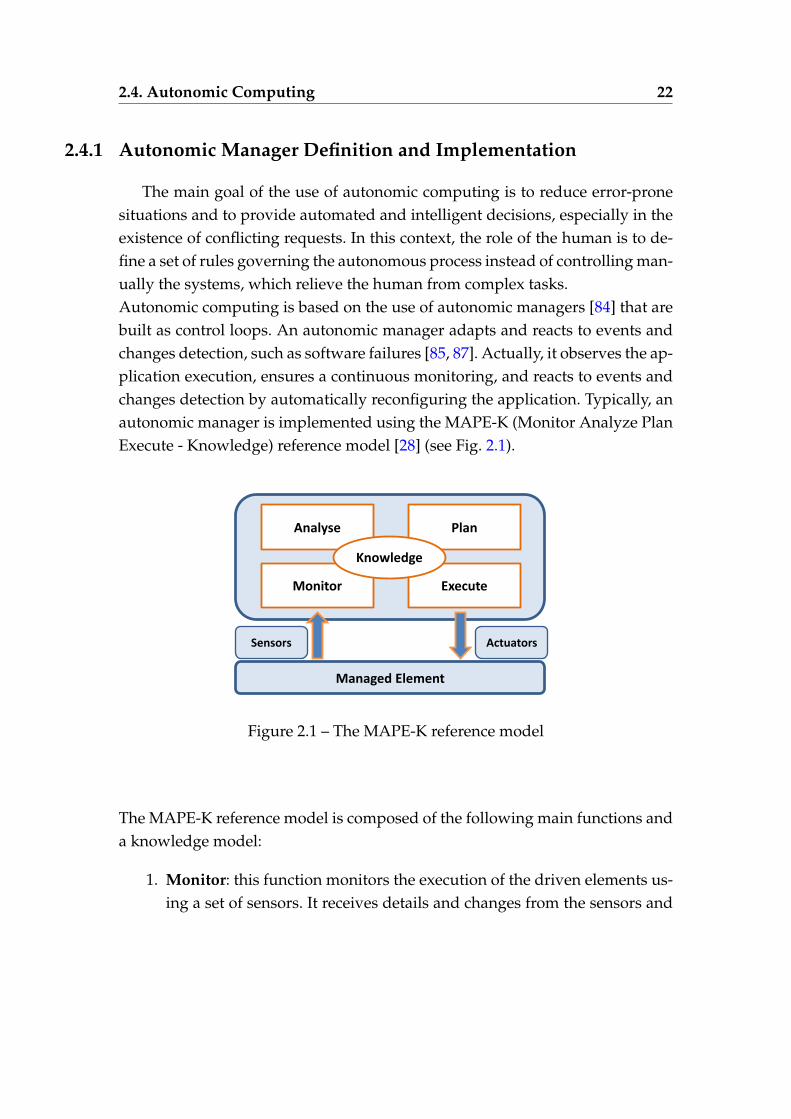
The main goal of the use of autonomic computing is to reduce error-pronesituations and to provide automated and intelligent decisions, especially in theexistence of conflicting requests. In this context, the role of the human is to de-fine a set of rules governing the autonomous process instead of controlling man-ually the systems, which relieve the human from complex tasks.Autonomic computing is based on the use of autonomic managers [84] that arebuilt as control loops. An autonomic manager adapts and reacts to events andchanges detection, such as software failures [85, 87]. Actually, it observes the ap-plication execution, ensures a continuous monitoring, and reacts to events andchanges detection by automatically reconfiguring the application. Typically, anautonomic manager is implemented using the MAPE-K (Monitor Analyze PlanExecute - Knowledge) reference model [28] (see Fig. 2.1).
Analyse Plan
Execute Monitor
Knowledge
Managed Element
Sensors Actuators
Figure 2.1 – The MAPE-K reference model
The MAPE-K reference model is composed of the following main functions anda knowledge model:
1. Monitor: this function monitors the execution of the driven elements us-ing a set of sensors. It receives details and changes from the sensors and
2.4. Autonomic Computing 23
then, generates information (e.g., failure, overload, underload) which aresent to the analyze function.
2. Analyse: this function analyzes the information received from the moni-tor function and then, takes decisions to change or not the managed sys-tem. It sends the decision to the plan function.
3. Plan: this function, after receiving the decision from the analyze function,generates a reconfiguration program that contains the required reconfig-uration operations. The program is transferred to the execute function.
4. Execute: this function executes the reconfiguration operations that areapplied through a set of actuators on the managed element.
5. Knowledge: this model is used by an autonomic manager as a basis forthe administrative decisions. It provides information that the autonomicmanager may maintain about the managed element.
The increasing complexity of applications implies the use of various andheterogeneous autonomic managers in the same system. Multiple researchstudies have demonstrated the importance of using autonomic managers. To-day, multiple managers are designed to ensure administrative tasks. Exam-ples of autonomic managers include the self-healing and self-protecting man-agers [112, 33, 103].
2.4.2 Coordinating Multiple Autonomic Managers
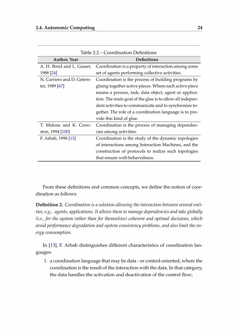
Today, using an entirely autonomous system, in which all the administra-tive functions are ensured, requires the use of multiple autonomic managers.In this context, when several managers monitor the same system, they shouldnecessarily take coherent decisions. Therefore, we must coordinate all the usedmanagers in order to enable them to make coherent self-management decisions.We present in Table 2.4.2 some definitions of coordination proposed in the liter-ature.
2.4. Autonomic Computing 24
Table 2.2 – Coordination DefinitionsAuthor, Year Definitions
A. H. Bond and L. Gasser,1988 [24]
Coordination is a property of interaction among someset of agents performing collective activities.
N. Carriero and D. Gelern-ter, 1989 [67]
Coordination is the process of building programs bygluing together active pieces. Where each active piecemeans a process, task, data object, agent or applica-tion. The main goal of the glue is to allow all indepen-dent activities to communicate and to synchronize to-gether. The role of a coordination language is to pro-vide this kind of glue.
T. Malone and K. Crow-ston, 1994 [100]
Coordination is the process of managing dependen-cies among activities.
F. Arbab, 1998 [13] Coordination is the study of the dynamic topologiesof interactions among Interaction Machines, and theconstruction of protocols to realize such topologiesthat ensure well-behavedness.
From these definitions and common concepts, we define the notion of coor-dination as follows:
Definition 2. Coordination is a solution allowing the interaction between several enti-ties, e.g., agents, applications. It allows them to manage dependencies and take globally(i.e., for the system rather than for themselves) coherent and optimal decisions, whichavoid performance degradation and system consistency problems, and also limit the en-ergy consumption.
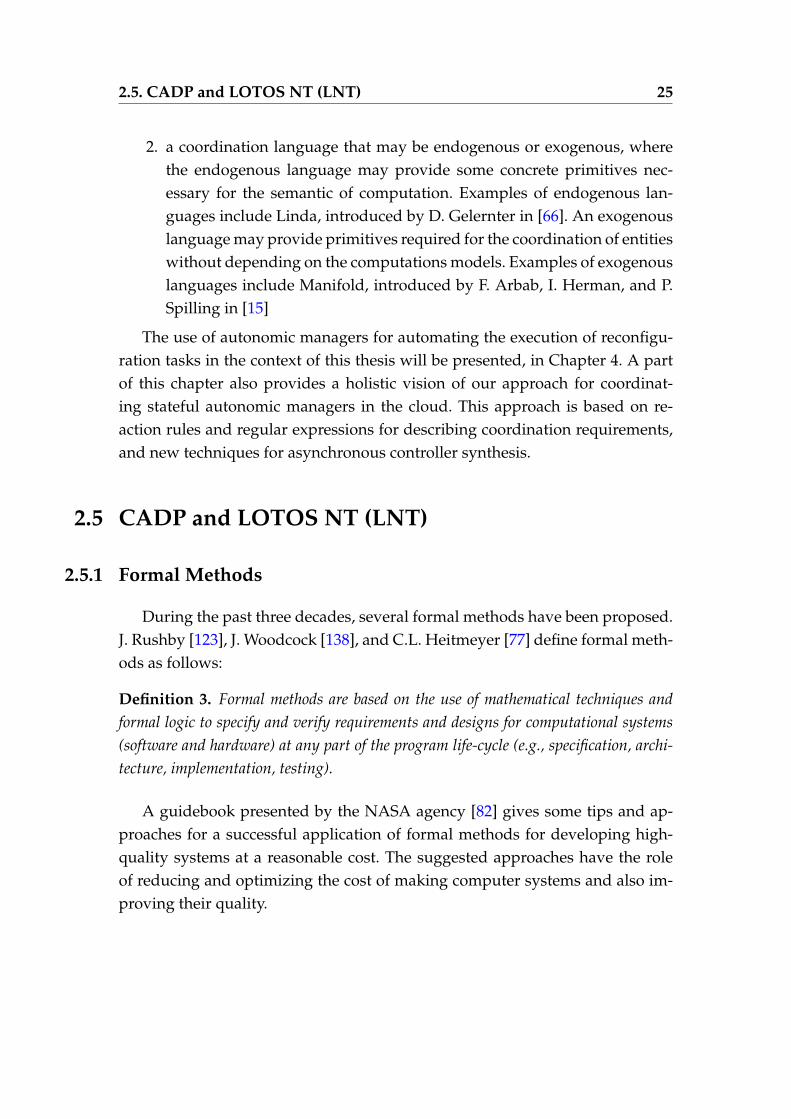
In [13], F. Arbab distinguishes different characteristics of coordination lan-guages:
1. a coordination language that may be data - or control-oriented, where thecoordination is the result of the interaction with the data. In that category,the data handles the activation and deactivation of the control flow;
2.5. CADP and LOTOS NT (LNT) 25
2. a coordination language that may be endogenous or exogenous, wherethe endogenous language may provide some concrete primitives nec-essary for the semantic of computation. Examples of endogenous lan-guages include Linda, introduced by D. Gelernter in [66]. An exogenouslanguage may provide primitives required for the coordination of entitieswithout depending on the computations models. Examples of exogenouslanguages include Manifold, introduced by F. Arbab, I. Herman, and P.Spilling in [15]
The use of autonomic managers for automating the execution of reconfigu-ration tasks in the context of this thesis will be presented, in Chapter 4. A partof this chapter also provides a holistic vision of our approach for coordinat-ing stateful autonomic managers in the cloud. This approach is based on re-action rules and regular expressions for describing coordination requirements,and new techniques for asynchronous controller synthesis.
2.5 CADP and LOTOS NT (LNT)
2.5.1 Formal Methods
During the past three decades, several formal methods have been proposed.J. Rushby [123], J. Woodcock [138], and C.L. Heitmeyer [77] define formal meth-ods as follows:
Definition 3. Formal methods are based on the use of mathematical techniques andformal logic to specify and verify requirements and designs for computational systems(software and hardware) at any part of the program life-cycle (e.g., specification, archi-tecture, implementation, testing).
A guidebook presented by the NASA agency [82] gives some tips and ap-proaches for a successful application of formal methods for developing high-quality systems at a reasonable cost. The suggested approaches have the roleof reducing and optimizing the cost of making computer systems and also im-proving their quality.
2.5. CADP and LOTOS NT (LNT) 26
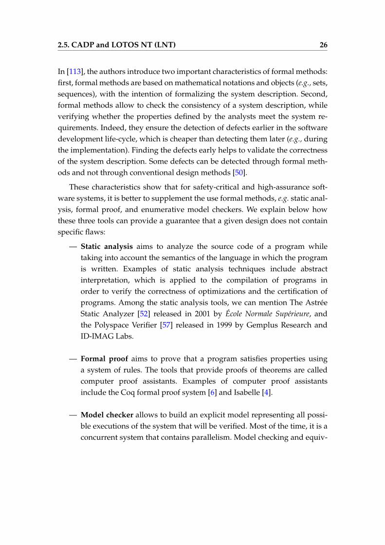
In [113], the authors introduce two important characteristics of formal methods:first, formal methods are based on mathematical notations and objects (e.g., sets,sequences), with the intention of formalizing the system description. Second,formal methods allow to check the consistency of a system description, whileverifying whether the properties defined by the analysts meet the system re-quirements. Indeed, they ensure the detection of defects earlier in the softwaredevelopment life-cycle, which is cheaper than detecting them later (e.g., duringthe implementation). Finding the defects early helps to validate the correctnessof the system description. Some defects can be detected through formal meth-ods and not through conventional design methods [50].
These characteristics show that for safety-critical and high-assurance soft-ware systems, it is better to supplement the use formal methods, e.g. static anal-ysis, formal proof, and enumerative model checkers. We explain below howthese three tools can provide a guarantee that a given design does not containspecific flaws:
— Static analysis aims to analyze the source code of a program whiletaking into account the semantics of the language in which the programis written. Examples of static analysis techniques include abstractinterpretation, which is applied to the compilation of programs inorder to verify the correctness of optimizations and the certification ofprograms. Among the static analysis tools, we can mention The AstréeStatic Analyzer [52] released in 2001 by École Normale Supérieure, andthe Polyspace Verifier [57] released in 1999 by Gemplus Research andID-IMAG Labs.
— Formal proof aims to prove that a program satisfies properties usinga system of rules. The tools that provide proofs of theorems are calledcomputer proof assistants. Examples of computer proof assistantsinclude the Coq formal proof system [6] and Isabelle [4].
— Model checker allows to build an explicit model representing all possi-ble executions of the system that will be verified. Most of the time, it is aconcurrent system that contains parallelism. Model checking and equiv-
2.5. CADP and LOTOS NT (LNT) 27
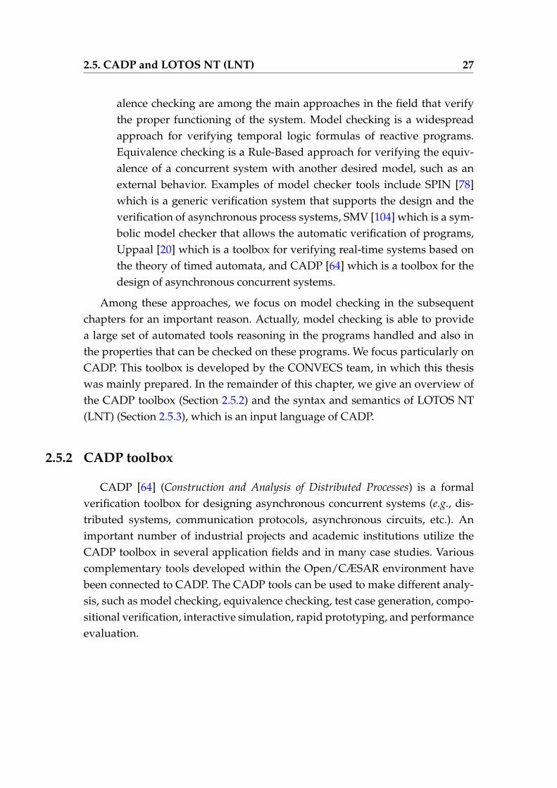
alence checking are among the main approaches in the field that verifythe proper functioning of the system. Model checking is a widespreadapproach for verifying temporal logic formulas of reactive programs.Equivalence checking is a Rule-Based approach for verifying the equiv-alence of a concurrent system with another desired model, such as anexternal behavior. Examples of model checker tools include SPIN [78]which is a generic verification system that supports the design and theverification of asynchronous process systems, SMV [104] which is a sym-bolic model checker that allows the automatic verification of programs,Uppaal [20] which is a toolbox for verifying real-time systems based onthe theory of timed automata, and CADP [64] which is a toolbox for thedesign of asynchronous concurrent systems.
Among these approaches, we focus on model checking in the subsequentchapters for an important reason. Actually, model checking is able to providea large set of automated tools reasoning in the programs handled and also inthe properties that can be checked on these programs. We focus particularly onCADP. This toolbox is developed by the CONVECS team, in which this thesiswas mainly prepared. In the remainder of this chapter, we give an overview ofthe CADP toolbox (Section 2.5.2) and the syntax and semantics of LOTOS NT(LNT) (Section 2.5.3), which is an input language of CADP.
2.5.2 CADP toolbox
CADP [64] (Construction and Analysis of Distributed Processes) is a formalverification toolbox for designing asynchronous concurrent systems (e.g., dis-tributed systems, communication protocols, asynchronous circuits, etc.). Animportant number of industrial projects and academic institutions utilize theCADP toolbox in several application fields and in many case studies. Variouscomplementary tools developed within the Open/CÆSAR environment havebeen connected to CADP. The CADP tools can be used to make different analy-sis, such as model checking, equivalence checking, test case generation, compo-sitional verification, interactive simulation, rapid prototyping, and performanceevaluation.
2.5. CADP and LOTOS NT (LNT) 28
2.5.2.1 Process Algebras
CADP uses process algebras for formally modeling concurrent systems. Pro-cess algebras rely on well-defined semantics. It allows us to verify propertiesof concurrent systems, which communicate and exchange data with synchro-nization and also, to describe systems execution in terms of Labelled TransitionSystems (LTSs). In this context, transitions figuring in the LTSs represent thecommunication between different processes. Leading examples of process alge-bras include CCS (Calculus of Communicating Systems) [107, 117], CSP (Theoryof Communicating Sequential Processes) [31], and ACP (Algebra of Commu-nicating Processes) [21]. Some languages, such as OCCAM [35], µCRL (microCommon Representation Language) [72], and LOTOS (Language Of TemporalOrdering Specification) [80], combine concepts from process algebraic with fea-tures from classical programming languages.Initially, CADP used LOTOS as main specific language. The recent versions ofCADP use LOTOS NT (LNT) [42], which is a simplified and improved versionof LOTOS. An automatic translator is developed within the CADP toolbox thatensures the transformation of LNT specifications to LOTOS specifications. EachLOTOS specification can be compiled into a Labelled Transition System (LTS),which enumerates all the possible executions of the corresponding specifica-tion. Last but not least, CADP provides scripting languages (e.g., SVL [64]) fordescribing verification scenarios.
2.5.2.2 CADP Tools
CADP is a rich toolbox, which provides several tools and libraries dedicatedto the manipulation of LOTOS and LNT specifications, of Labelled TransitionsSystems (explicit 9 and implicit 10), and of temporal logic formulas. It imple-ments a broad range of optimized state space exploration techniques and verifi-cation tools that can be used to make various kinds of analysis [63], e.g., model
9. An explicit LTS usually describes an expected service, where the states and transitionscomposing it are listed exhaustively.
10. An implicit LTS usually describes a protocol, where states and transitions are given incomprehension.
2.5. CADP and LOTOS NT (LNT) 29
checking and equivalence checking.
Tools for Labelled Transition Systems
CADP contains several tools dedicated to the manipulation of explicit (suchas Bcg graphs) and implicit (explored on the fly) LTSs.Bcg (Binary Coded Graphs) is a format for the LTSs representation and a soft-ware environment for handling this format. It has a central role in CADP. Itincludes several tools, e.g., Bcg_draw, which gives a graphical representation ofBcg graphs, Bcg_edit, which allows to modify manually the graph generated byBcg_draw, and Bcg_min, which reduces graphs via strong or branching bisim-ulation.Open/CÆSAR is a generic software environment that has the advantages ofdeveloping tools, which explore graphs on the fly. Open/CÆSAR plays a cen-tral role in CADP. It allows connection to the CADP tools (language-orientedtools and model-oriented tools). Examples of tools written in the Open/CÆSARframework include Bisimulator (for comparing two LTSs modulo a given equiv-alence), Reductor (for eliminating tau-transitions/duplicate transitions and de-terminizing graphs), Evaluator (the on-the-fly model checker of CADP), andExecutor (a random execution tool).The connection between explicit and implicit models is ensured by several com-pilers, such as CÆSAR.OPEN for models expressed as LOTOS specifications,Bcg_OPEN for models represented as Bcg graphs, EXP.OPEN for models ex-pressed as communicating automata, and SEQ.OPEN for models representedas execution traces.
Tools for equivalence checking
Equivalence checking is a verification technique that consists of comparingthe description of a system behavior with the description of its desired exter-nal behavior modulo a given equivalence relation [81]. It also targets minimiz-ing explicit graphs. Examples of tools dedicated to equivalence checking in-clude Bcg_min, for minimizing explicit LTS, Bcg_cmp for comparing two ex-plicit LTSs, and Bisimulator for comparing two LTSs modulo a given equiva-lence.
2.5. CADP and LOTOS NT (LNT) 30
Tools for model checking
Model checking is a verification technique, which explores all the possiblestates of a system [95, 17] and checks that the system satisfies a set of propertiesrepresented by temporal logic formulas. Classical tools used for model check-ing include XTL (eXecutable Temporal Language), which explores and queriesexplicit LTSs presented in the Bcg format, Evaluator3, and recently Evaluator4,which handles formulas described in the temporal logic formalism MCL (ModelChecking Language) [102]. MCL presents an extension of alternation-free µ-calculus and is equipped with regular expressions, data-based constructs, andfairness operators. In this thesis, we used MCL to specify two groups of proper-ties: (1) those allowing us to verify the protocol that we propose to reconfiguredynamically distributed cloud applications (Chapter 4); and (2) those allow-ing us to verify the controller generated with the new asynchronous synthesistechniques we propose (Chapter 5). We use model checking to verify that theseproperties are respected.
Tools for Visual checking
Visual checking is a technique that allows the visualization and edition ofBcg graphs. CADP tools dedicated to visual checking include Bcg_draw andBcg_edit.
Tools for compositional verification
Compositional verification is a technique implemented within CADP andused to fight state explosion when applying enumerative verifications of com-plex concurrent systems. Examples of tools that support the compositionalchecking include EXP.OPEN, projector, and SVL (Script Verification Language),which aims at automating the generation, minimization, hiding, and verifica-tion of the LTSs.
Tools for LOTOS and LNT
CADP contains several compilers, which allow the transformation of theLOTOS and LNT specifications to other languages and graphs, such as C or fi-nite graphs. Multiple transformations are ensured using lnt2lotos, which trans-lates a source program, described as a set of LNT processes, into either LOTOS.
2.5. CADP and LOTOS NT (LNT) 31
CÆSAR.ADT translates LOTOS data types into C types and functions.
During this thesis, we have used several tools available in CADP, in par-ticular, tools for Labelled Transition Systems, model checking, and equivalencechecking. Last but not least, there exist other tools, which are also available inCADP and used for distributed verification, testing, and performance evalua-tion.
2.5.3 LOTOS NT (LNT)
LNT is an input language of CADP, which is supported by the LNT.OPENtool. It is a simplified and improved version of LOTOS. LNT relies on an impera-tive specification language that makes its writing and understanding much sim-pler. In 1993, ISO/IEC defined a revised version of the LOTOS standard. Then,the CONVECS team defined a simplified version, called LOTOS NT (LNT).
As stated before, LNT and CADP are chosen in this thesis. This choice is mo-tivated by several reasons. First, LNT is an expressive process language withformal and operational semantics. It combines the asynchronous parallelisminherited from process algebra with the user-friendly syntax inherited from im-perative and functional programming languages. Second, LNT is supported byCADP, a toolbox that contains optimized state space exploration techniques andverification tools (see Section 2.5.2).
2.5.3.1 LNT grammar
The behavioural part of the LNT specification language consists of the fol-lowing constructs: actions with input/output parameters, assignment (:=), se-quential composition (;), non-deterministic choice (select), conditional structure(if), breakable loop (loop and break), empty statement (null), and parallel com-position (par). Each process defines an alphabet of actions, a list of typed pa-rameters, and a behavior built using the aforementioned operators. Communi-cation is carried out by rendezvous on actions with a bidirectional transmissionof multiple values. The parallel composition explicitly declares the set of actionson which processes must synchronize. If the processes evolve independently
2.6. Conclusion 32
from one another (interleaving), this set is empty. The semantics of LNT pro-grams are defined in [41] using Structural Operational Semantics (SOS) rules.We adopt the following notations to present the LNT identifiers: M for modules,T for types, X for variables, F for functions, L for loop labels, B for behaviors, Γfor channels, G for gates, and Π for processes.We present in Appendix A an excerpt of the LNT process grammar.
Each LNT process is composed of three parts: an alphabet of actions, a set oftyped parameters, and a behavior built using the constructs as mentioned ear-lier. The LNT language provides communication semantics that rely on multi-way rendezvous on actions with bidirectional transmissions of value exchangeon the same gate. Each action may be followed by a sent value (!) or receivevalue (?). The parallel composition explicitly declares the set of actions on whichtwo processes or more must synchronize. If the processes evolve independentlyfrom one another (interleaving), this set is empty (the "par" is not followed byactions).
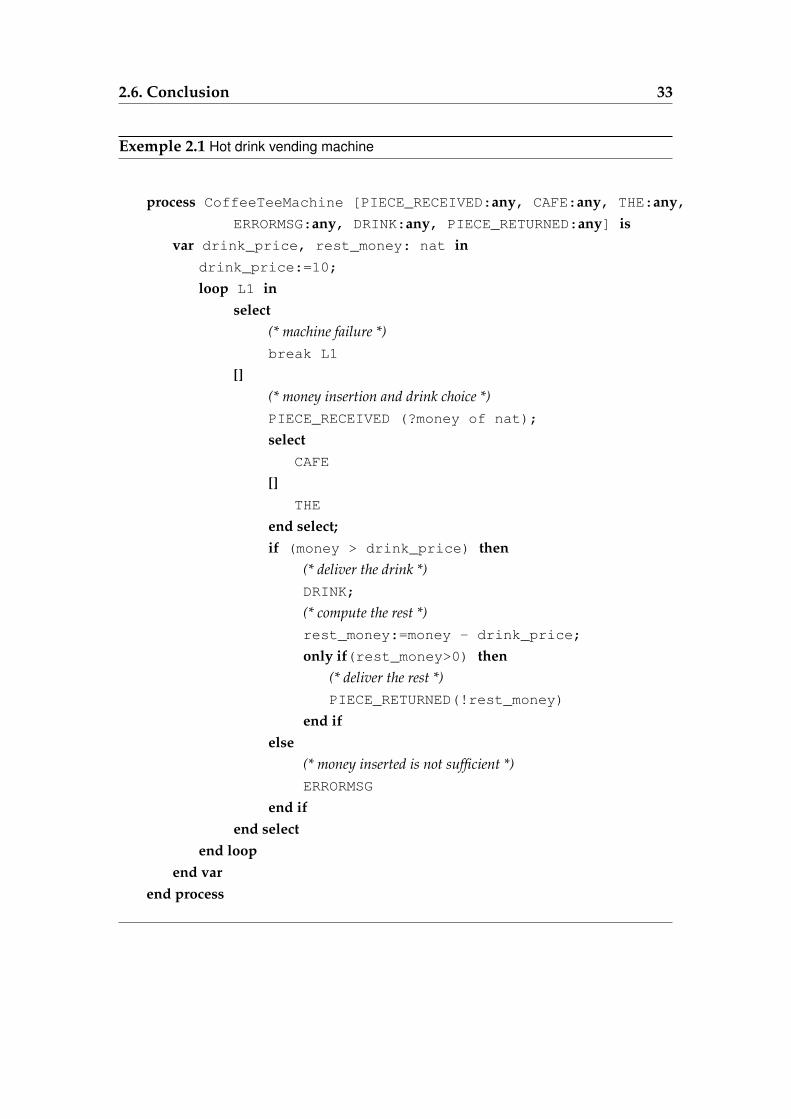
For illustration purposes, we give an example (see Example 2.1), which de-scribes the behavior of an automatic hot drink vending machine. The exampleshows how the machine, if it is not failing, is always waiting to distribute adrink. Once the customer inserts money, he can choose a certain drink (coffeeor tea). Then, the machine returns an error message if the client did not insertenough money or delivers the drink and the rest of the money.
2.6 Conclusion
We have presented in this chapter some general background used to sup-port the thesis. The chapter begins with some definitions and general character-istics of distributed applications, cloud computing, dynamic reconfiguration,and autonomic computing. It also presents well-known definitions of coordina-tion proposed in the literature. Finally, we have surveyed existing formal tech-niques and tools, which motivate the use of the LNT specification language andmodel checking in order to specify and verify the dynamic reconfiguration ofdistributed applications and the coordination of stateful autonomic managers
2.6. Conclusion 33
Exemple 2.1 Hot drink vending machine
process CoffeeTeeMachine [PIECE_RECEIVED:any, CAFE:any, THE:any,ERRORMSG:any, DRINK:any, PIECE_RETURNED:any] is
var drink_price, rest_money: nat indrink_price:=10;
loop L1 inselect
(* machine failure *)break L1
[](* money insertion and drink choice *)PIECE_RECEIVED (?money of nat);
selectCAFE
[]THE
end select;if (money > drink_price) then
(* deliver the drink *)DRINK;
(* compute the rest *)rest_money:=money - drink_price;
only if(rest_money>0) then(* deliver the rest *)PIECE_RETURNED(!rest_money)
end ifelse
(* money inserted is not sufficient *)ERRORMSG
end ifend select
end loopend var
end process

2.6. Conclusion 34
in the cloud.
3State of the Art
" No one wants to learn from mistakes, but we cannot learn enough from successesto go beyond the state of the art. "
Henry Petroski
Contents
3.1 Dynamic Reconfiguration . . . . . . . . . . . . . . . . . . . . . . 37
3.1.1 Reconfiguration in the Context of Cloud Computing . 38
3.1.2 Reconfiguration in the Context of Component-BasedSystems . . . . . . . . . . . . . . . . . . . . . . . . . . . 46
3.1.3 Summary . . . . . . . . . . . . . . . . . . . . . . . . . . 49
3.2 Coordination Models and Languages . . . . . . . . . . . . . . . 51
3.2.1 Data-driven Coordination Models and Languages . . . 51
3.2.2 Control- and Event-Driven Coordination Models andLanguages . . . . . . . . . . . . . . . . . . . . . . . . . . 53
36
3.2.3 Coordination Using Rule Agents and Decision Policies 57
3.2.4 Coordination Using Utility-Functions . . . . . . . . . . 58
3.2.5 Coordination Using Shared Knowledge . . . . . . . . . 60
3.3 Controller Synthesis Techniques . . . . . . . . . . . . . . . . . . 62
3.3.1 Original Theory for Controller Synthesis Techniques . 62
3.3.2 Modular Discrete Controller Synthesis Using Syn-chronous Language BZR . . . . . . . . . . . . . . . . . . 64
3.3.3 Synthesis of Decentralised Supervisors for Dis-tributed Adaptive Systems . . . . . . . . . . . . . . . . 66
3.3.4 A Framework for the Coordination of Multiple Auto-nomic Managers in Cloud Environments . . . . . . . . 68
3.3.5 Summary . . . . . . . . . . . . . . . . . . . . . . . . . . 68
3.1. Dynamic Reconfiguration 37
WE review in the first part of this chapter existing languages and ap-proaches that have been used to reconfigure applications (e.g., dis-
tributed applications), including a comparison of the features and limitationsof the reviewed approaches. The second part of the chapter overviews somewell-known techniques for coordinating entities, including the coordination ofautonomic managers. Finally, controller synthesis techniques are surveyed.
3.1 Dynamic Reconfiguration
In the last 20 years, dynamic reconfiguration has been an active researchtopic with the advent of distributed applications. It has been studied in severalresearch areas that include software architecture [16, 115, 105, 97, 88, 9, 68] (e.g.,software architecture in the cloud), graph transformation [133, 8, 90], and recon-figuration patterns [32, 70, 116].In [88, 97, 99, 98, 9, 133, 36, 124, 90], the authors propose various formal modelsand languages, such as Darwin and SmartFrog to specify dynamic reconfig-uration of component-based systems and distributed applications whose con-figurations can evolve (addition/removal of components and connections) atrun-time. Some of these approaches are based on Architecture Description Lan-guages (ADLs) that have textual and/or graphical syntax used to specify soft-ware architectures. In this context, the purpose of an ADL is allowing bothdevelopers and clients to reason together in order to provide understandablesystem abstractions. Multiple ADLs are used in several fields of studies and in-dustries, but few of them offer a description of dynamic software architectures,where dynamic reconfiguration operations are strongly required.Let us summarize in the following paragraphs the languages and approachesthat have been suggested for the specification, deployment, and dynamic re-configuration of distributed systems and component-based systems. These ap-proaches attempt to address three major challenges, which are: (1) deployingand managing distributed applications, e.g., cloud applications; (2) defining re-configuration plannings that must be performed; and (3) automating the (inter)connection of software components in order to realize desired target architec-tures.
3.1. Dynamic Reconfiguration 38
We will show that some of these languages and approaches concentrate on onesingle challenge (e.g., designing a target architecture), while others try to tacklemore than one challenge in a unified manner.Some of these languages and approaches are used in the context of cloud com-putation, whereas others are used for component-based systems.
3.1.1 Reconfiguration in the Context of Cloud Computing
3.1.1.1 DADL and SmartFrog Languages
In [108], the authors propose DADL (Distributed Application DescriptionLanguage), a language for managing virtual resources. DADL allows the ex-pression of constraints on resources in terms of service level agreements (SLAs)and elasticity rules when describing an application architecture with its avail-able resources. The DADL language is an extension of the open source Smart-Frog project (Smart Framework for Object Groups), which is a Java-basedframework, developed at Hewlett-Packard European Research Laboratories inBristol [69], and tested on client and server operating systems. SmartFrog, writ-ten in Java, can be implemented in any operating system that supports Javavirtual machines (JVMs). It is used to configure, deploy, manage, and describethe needs of distributed software systems. SmartFrog is based on available re-sources and declarative descriptions of the components that compose the ap-plication. The SmartFrog component model is composed of the following threeparts:
— configuration data are defined in a uniform way using standardizedAPIs. It may refer to the components themselves or references to othercomponents. For each configuration data, an initialized phase is definedto specify if it will be initialized statically via the application descrip-tion or generated dynamically according to the requirements defined atrun-time. The SmartFrog component model includes two mechanisms:composition and extension. The composition mechanism allows the useof a component description as an attribute in another one, while the ex-tension mechanism allows the combination of separated components de-
3.1. Dynamic Reconfiguration 39
scriptions as an attribute in a reference which does not have a descrip-tion;
— a life-cycle manager uses the configuration data and multiple specificmethods to drive a configuration when creating, initializing, starting,stopping a component, and also consulting its state. The SmartFrog al-lows the description of a system as a group of components. The inter-related components can present software, data, and also hardware. Eachcomponent is bound to other components through parent-child relation-ships. In the same system, different components communicate with eachother via the SmartFrog framework. The configuration data of the sys-tem members may be inter-related with one life-cycle manager, whichemerges from the life-cycles of all the system members (i.e., the compo-nents that compose the system). The set of systems is independent, butSmartFrog provides a discovery process that locates them. The life-cyclemanagers allow to initialize, implement, and monitor the application ina deployed system;
— a managed entity presents the component functionality. It uses configu-ration details to give an interpretation of the component description.
Finally, SmartFrog provides an automated and optimal allocation of cloud re-sources. It allows its users to build and deploy their running management sys-tems. However, it requires specific components to deploy the system automati-cally.
Evaluation
SmartFrog supports distributed application deployment and also allows theautomation of the component instantiation, initialization, and startup phases,but not the application deployment. It presents some similarities with our ap-proach. However, contrary to us, it does not explain either how a life-cycle man-ager preserves architectural invariants when stopping a running system. It doesnot explain either how it manages the component failures. Furthermore, it is notan open source product and has the following limitations:
— the SmartFrog framework requires the use of nodes to install a Java Vir-tual Machine;
— SmartFrog does not allow to deal with software installation manage-
3.1. Dynamic Reconfiguration 40
ment.
3.1.1.2 RESERVOIR project
In [44], the authors discuss the implications of architecture definition for dis-tributed applications that are deployed on cloud environments. The authorsalso propose configuration protocols, which are based on Application Descrip-tion Languages (ADLs). The ADL is used to define a contract, between an IaaSprovider and an application developer, in which the IaaS provider can meetsome QoS objectives. A defined contract contains a specification of architecturalconstraints and invariants at runtime used to explain how software architec-tures must be described. The authors also adopt, for the manifested language,a model-driven approach with extensions of the Essential Meta-Object Facil-ity (EMOF) abstract syntax, which is defined by the initiative Model DrivenArchitecture (MDA) of the Object Management Group (OMG). The model isused to describe a distributed application, its requirements towards the under-lying execution platforms, its architectural constraints (e.g., concerning place-ment, collocation, and startup/stopping order), elasticity rules that must be de-clared when deploying an application on the cloud environment, and finallynew abstractions (e.g., specification of on-demand scaling). The requirements,constraints, and rules are used to describe when and how the application mustconsume more/fewer resources from the cloud. In this work, the proposed ar-chitecture targets at supporting the abstractions and specifying clear semanticfor the ADL, while respecting the architecture using denotational approach. Asfor the deployment mechanism, components are deployed on the RESERVOIR-based infrastructure, which is provided by the RESERVOIR project [121].
Evaluation
This approach proposes an architectural description that can evolve at run-time. However, these works still have some limitations, which are:
— the approach guarantees the application deployment, but not in a decen-tralized fashion, which harms the scalability of applications that can bedeployed;
— this approach does not explain the order of the component instantiations
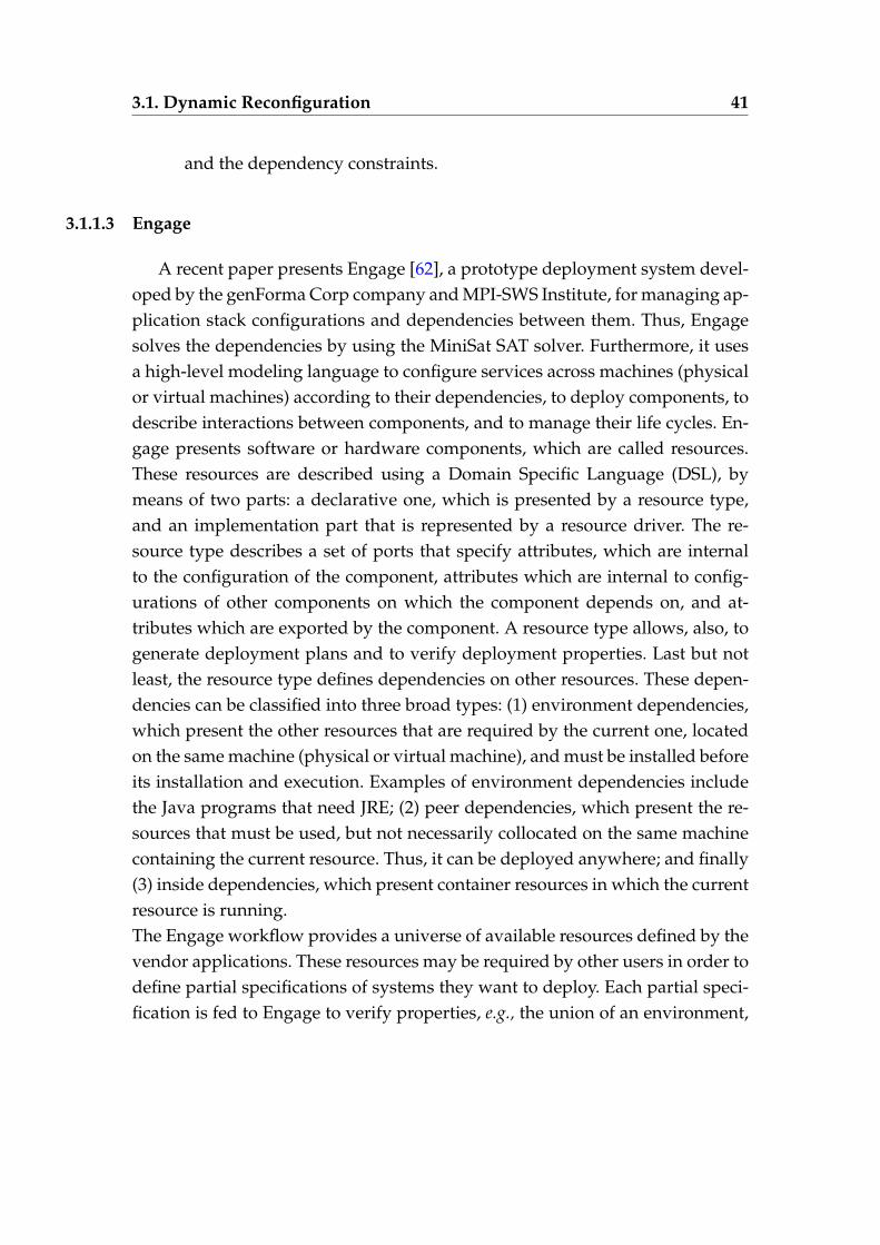
3.1. Dynamic Reconfiguration 41
and the dependency constraints.
3.1.1.3 Engage
A recent paper presents Engage [62], a prototype deployment system devel-oped by the genForma Corp company and MPI-SWS Institute, for managing ap-plication stack configurations and dependencies between them. Thus, Engagesolves the dependencies by using the MiniSat SAT solver. Furthermore, it usesa high-level modeling language to configure services across machines (physicalor virtual machines) according to their dependencies, to deploy components, todescribe interactions between components, and to manage their life cycles. En-gage presents software or hardware components, which are called resources.These resources are described using a Domain Specific Language (DSL), bymeans of two parts: a declarative one, which is presented by a resource type,and an implementation part that is represented by a resource driver. The re-source type describes a set of ports that specify attributes, which are internalto the configuration of the component, attributes which are internal to config-urations of other components on which the component depends on, and at-tributes which are exported by the component. A resource type allows, also, togenerate deployment plans and to verify deployment properties. Last but notleast, the resource type defines dependencies on other resources. These depen-dencies can be classified into three broad types: (1) environment dependencies,which present the other resources that are required by the current one, locatedon the same machine (physical or virtual machine), and must be installed beforeits installation and execution. Examples of environment dependencies includethe Java programs that need JRE; (2) peer dependencies, which present the re-sources that must be used, but not necessarily collocated on the same machinecontaining the current resource. Thus, it can be deployed anywhere; and finally(3) inside dependencies, which present container resources in which the currentresource is running.The Engage workflow provides a universe of available resources defined by thevendor applications. These resources may be required by other users in order todefine partial specifications of systems they want to deploy. Each partial speci-fication is fed to Engage to verify properties, e.g., the union of an environment,
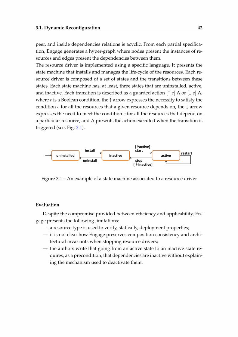
3.1. Dynamic Reconfiguration 42
peer, and inside dependencies relations is acyclic. From each partial specifica-tion, Engage generates a hyper-graph where nodes present the instances of re-sources and edges present the dependencies between them.The resource driver is implemented using a specific language. It presents thestate machine that installs and manages the life-cycle of the resources. Each re-source driver is composed of a set of states and the transitions between thesestates. Each state machine has, at least, three states that are uninstalled, active,and inactive. Each transition is described as a guarded action [↑ c] A or [↓ c] A,where c is a Boolean condition, the ↑ arrow expresses the necessity to satisfy thecondition c for all the resources that a given resource depends on, the ↓ arrowexpresses the need to meet the condition c for all the resources that depend ona particular resource, and A presents the action executed when the transition istriggered (see, Fig. 3.1).
uninstalled inactive active restart
install
uninstall
start
stop
[ active]
[ inactive]
Figure 3.1 – An example of a state machine associated to a resource driver
Evaluation
Despite the compromise provided between efficiency and applicability, En-gage presents the following limitations:
— a resource type is used to verify, statically, deployment properties;— it is not clear how Engage preserves composition consistency and archi-
tectural invariants when stopping resource drivers;— the authors write that going from an active state to an inactive state re-
quires, as a precondition, that dependencies are inactive without explain-ing the mechanism used to deactivate them.
3.1. Dynamic Reconfiguration 43
3.1.1.4 VAMP
In [59, 60, 126, 61], the authors describe a general solution, called VirtualApplications Management Platform (VAMP), that automates the configurationof distributed applications in the cloud environments. This solution is basedon a representation of distributed architectures. The framework VAMP extendsthe OVF (Open Virtualization Format) language, which is provided by the Dis-tributed Management Task Force (DMTF) and dedicated to uniform presenta-tions of applications running on virtual machines, with an ADL that describesthe global architecture of distributed applications. This extension provides anexplicit specification of the component building, interfaces, dependencies, andbinding between components. We present in Figure 3.2 an example of an appli-cation (left) and the extended OVF descriptor that corresponds to that applica-tion (right). The application is composed of three interconnected components,hosted on distinct virtual machines and called C0, C1, and C2, respectively. Eachcomponent has a server interface s with a set of client interfaces c and is con-nected to other components through bindings among its client interfaces andtheir service interfaces.
This solution also presents a decentralized and self-configuration deploymentprotocol that can be implemented on a compensation-based mechanism. In [61],the authors present a reliable self-deployment protocol, which represents anextension of the original deployment protocol VAMP [59]. This protocol canautomatically deploy cloud applications in a decentralized fashion, even in thecase of a finite number of virtual machine failures. Thus, the protocol supportsthe failures by detecting and repairing them, but it is not compatible with somereconfiguration features.
Evaluation
This solution introduces a protocol for deploying distributed applications.The protocol allows the automation of the application deployment, but itpresents some limitations, which are:
3.1. Dynamic Reconfiguration 44
C0
VM0
C1
VM1
VM2
s c
s
C2
c
s
c
<!-- Applicative architecture --> <AppArchitectureSection> <definition name=‘’application_name"> <component name="C0"> <interface name="c" role="client" .../> <interface name="s" role="server" .../> ... <virtual-node name="VM0"/> </component> <component name="C1"> ... </component> <component name="C2"> ... </component> <binding client="C0.c" server="C1.s" /> <binding client="C0.c" server="C2.s" /> ... </definition> </AppArchitectureSection>
Figure 3.2 – An example of an application (left) and its extended OVF descriptor(right)
— in the applications, all elements are known from the beginning (e.g., num-bers of VMs and components, bindings between components);
— the protocol does not allow to modify the application at run-time.
3.1.1.5 Aeolus Component Model
In [91, 40], the authors present a design and an implementation of an ap-proach used for the automatic synthesis of deployment plans. This approachprovides a reconfiguration algorithm for deploying heterogeneous softwarecomponents and computing a sequence of actions to deploy the desired config-uration. This algorithm works in the presence of circular dependencies amongcomponents. To master the complexity of cloud applications, the authors pro-pose the Aeolus component model and explain how some activities, such as de-ployment, reconfiguration, and management phases of such applications (i.e.,cloud applications), can be automated in this model. Aeolus uses a set of avail-able components, where each component is regarded as a gray-box that ownsinternal states and mechanisms to change its state during the three phases. A
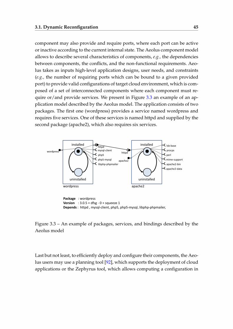
3.1. Dynamic Reconfiguration 45
component may also provide and require ports, where each port can be activeor inactive according to the current internal state. The Aeolus component modelallows to describe several characteristics of components, e.g., the dependenciesbetween components, the conflicts, and the non-functional requirements. Aeo-lus takes as inputs high-level application designs, user needs, and constraints(e.g., the number of requiring ports which can be bound to a given providedport) to provide valid configurations of target cloud environment, which is com-posed of a set of interconnected components where each component must re-quire or/and provide services. We present in Figure 3.3 an example of an ap-plication model described by the Aeolus model. The application consists of twopackages. The first one (wordpress) provides a service named wordpress andrequires five services. One of these services is named httpd and supplied by thesecond package (apache2), which also requires six services.
installed
uninstalled
httpd mysql-client
php5
php5-mysql
libphp-phpmailer
wordpress
installed
uninstalled
lsb-base
procps
perl
mime-support
apache2-bin
apache2
apache2-data
httpd wordpress
apache2
Package : wordpress Version : 3.0.5 + dfsg - 0 + squeeze 1 Depends : httpd , mysql-client, php5, php5-mysql, libphp-phpmailer,
Figure 3.3 – An example of packages, services, and bindings described by theAeolus model
Last but not least, to efficiently deploy and configure their components, the Aeo-lus users may use a planning tool [92], which supports the deployment of cloudapplications or the Zephyrus tool, which allows computing a configuration in
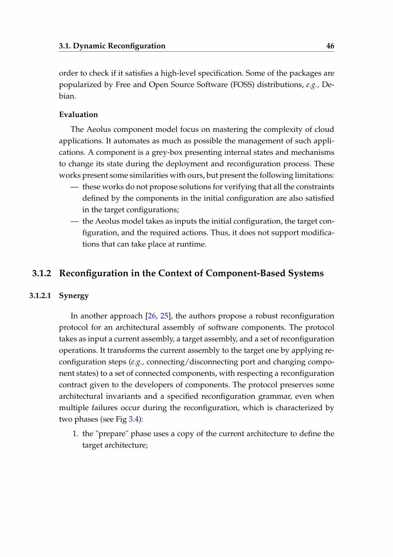
3.1. Dynamic Reconfiguration 46
order to check if it satisfies a high-level specification. Some of the packages arepopularized by Free and Open Source Software (FOSS) distributions, e.g., De-bian.
Evaluation
The Aeolus component model focus on mastering the complexity of cloudapplications. It automates as much as possible the management of such appli-cations. A component is a grey-box presenting internal states and mechanismsto change its state during the deployment and reconfiguration process. Theseworks present some similarities with ours, but present the following limitations:
— these works do not propose solutions for verifying that all the constraintsdefined by the components in the initial configuration are also satisfiedin the target configurations;
— the Aeolus model takes as inputs the initial configuration, the target con-figuration, and the required actions. Thus, it does not support modifica-tions that can take place at runtime.
3.1.2 Reconfiguration in the Context of Component-Based Systems
3.1.2.1 Synergy
In another approach [26, 25], the authors propose a robust reconfigurationprotocol for an architectural assembly of software components. The protocoltakes as input a current assembly, a target assembly, and a set of reconfigurationoperations. It transforms the current assembly to the target one by applying re-configuration steps (e.g., connecting/disconnecting port and changing compo-nent states) to a set of connected components, with respecting a reconfigurationcontract given to the developers of components. The protocol preserves somearchitectural invariants and a specified reconfiguration grammar, even whenmultiple failures occur during the reconfiguration, which is characterized bytwo phases (see Fig 3.4):
1. the "prepare" phase uses a copy of the current architecture to define thetarget architecture;
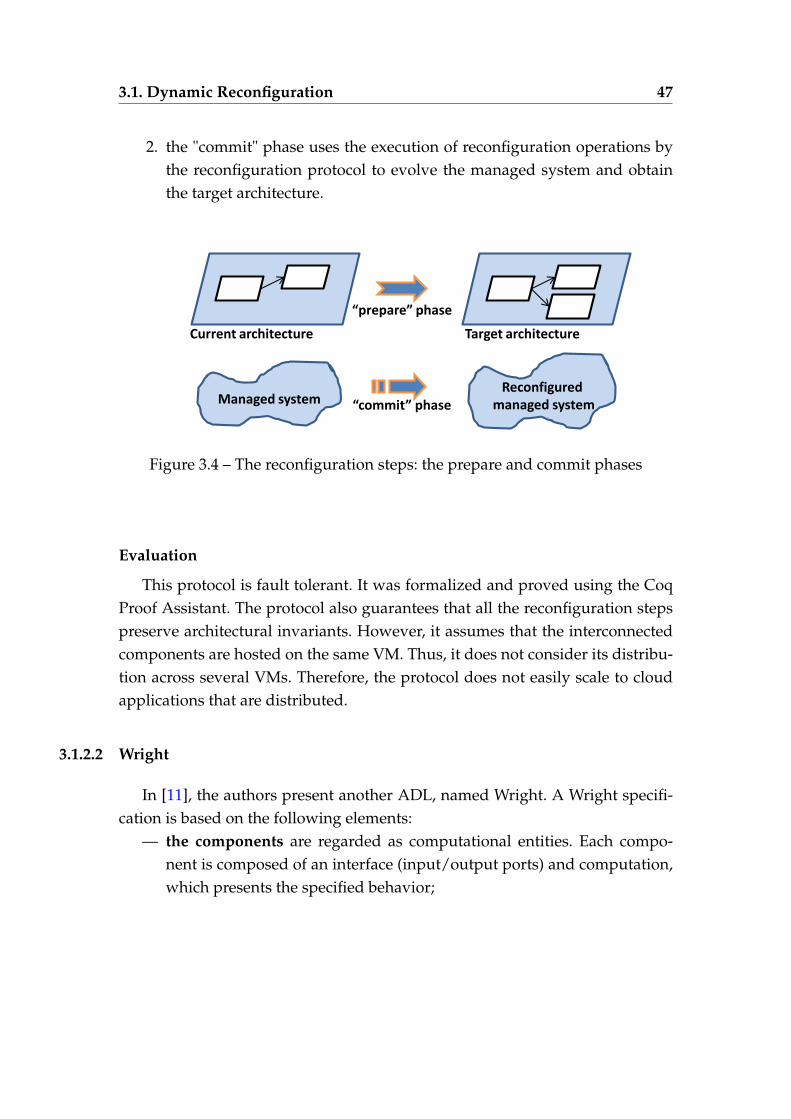
3.1. Dynamic Reconfiguration 47
2. the "commit" phase uses the execution of reconfiguration operations bythe reconfiguration protocol to evolve the managed system and obtainthe target architecture.
Current architecture Target architecture
“prepare” phase
Reconfigured
managed system
Managed system “commit” phase
Figure 3.4 – The reconfiguration steps: the prepare and commit phases
Evaluation
This protocol is fault tolerant. It was formalized and proved using the CoqProof Assistant. The protocol also guarantees that all the reconfiguration stepspreserve architectural invariants. However, it assumes that the interconnectedcomponents are hosted on the same VM. Thus, it does not consider its distribu-tion across several VMs. Therefore, the protocol does not easily scale to cloudapplications that are distributed.
3.1.2.2 Wright
In [11], the authors present another ADL, named Wright. A Wright specifi-cation is based on the following elements:
— the components are regarded as computational entities. Each compo-nent is composed of an interface (input/output ports) and computation,which presents the specified behavior;
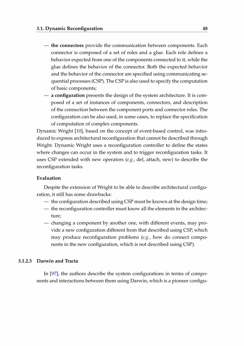
3.1. Dynamic Reconfiguration 48
— the connectors provide the communication between components. Eachconnector is composed of a set of roles and a glue. Each role defines abehavior expected from one of the components connected to it, while theglue defines the behavior of the connector. Both the expected behaviorand the behavior of the connector are specified using communicating se-quential processes (CSP). The CSP is also used to specify the computationof basic components;
— a configuration presents the design of the system architecture. It is com-posed of a set of instances of components, connectors, and descriptionof the connection between the component ports and connector roles. Theconfiguration can be also used, in some cases, to replace the specificationof computation of complex components.
Dynamic Wright [10], based on the concept of event-based control, was intro-duced to express architectural reconfiguration that cannot be described throughWright. Dynamic Wright uses a reconfiguration controller to define the stateswhere changes can occur in the system and to trigger reconfiguration tasks. Ituses CSP extended with new operators (e.g., del, attach, new) to describe thereconfiguration tasks.
Evaluation
Despite the extension of Wright to be able to describe architectural configu-ration, it still has some drawbacks:
— the configuration described using CSP must be known at the design time;— the reconfiguration controller must know all the elements in the architec-
ture;— changing a component by another one, with different events, may pro-
vide a new configuration different from that described using CSP, whichmay produce reconfiguration problems (e.g., how do connect compo-nents in the new configuration, which is not described using CSP).
3.1.2.3 Darwin and Tracta
In [97], the authors describe the system configurations in terms of compo-nents and interactions between them using Darwin, which is a pioneer configu-
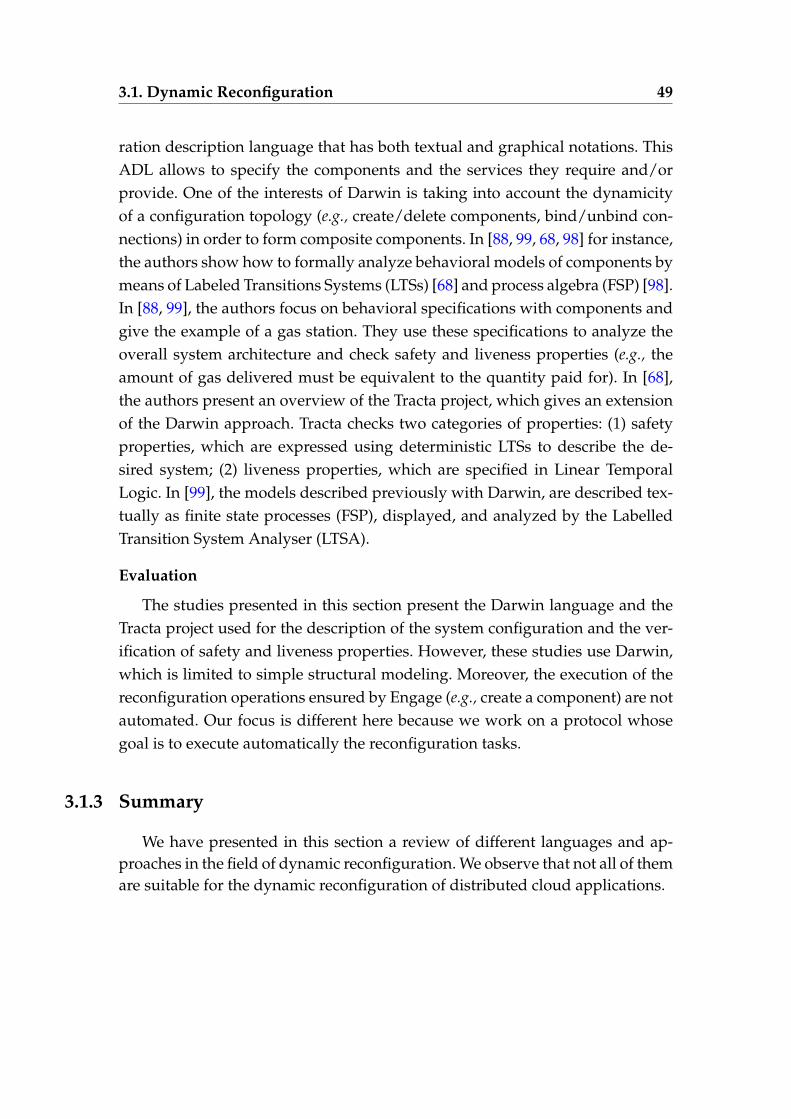
3.1. Dynamic Reconfiguration 49
ration description language that has both textual and graphical notations. ThisADL allows to specify the components and the services they require and/orprovide. One of the interests of Darwin is taking into account the dynamicityof a configuration topology (e.g., create/delete components, bind/unbind con-nections) in order to form composite components. In [88, 99, 68, 98] for instance,the authors show how to formally analyze behavioral models of components bymeans of Labeled Transitions Systems (LTSs) [68] and process algebra (FSP) [98].In [88, 99], the authors focus on behavioral specifications with components andgive the example of a gas station. They use these specifications to analyze theoverall system architecture and check safety and liveness properties (e.g., theamount of gas delivered must be equivalent to the quantity paid for). In [68],the authors present an overview of the Tracta project, which gives an extensionof the Darwin approach. Tracta checks two categories of properties: (1) safetyproperties, which are expressed using deterministic LTSs to describe the de-sired system; (2) liveness properties, which are specified in Linear TemporalLogic. In [99], the models described previously with Darwin, are described tex-tually as finite state processes (FSP), displayed, and analyzed by the LabelledTransition System Analyser (LTSA).
Evaluation
The studies presented in this section present the Darwin language and theTracta project used for the description of the system configuration and the ver-ification of safety and liveness properties. However, these studies use Darwin,which is limited to simple structural modeling. Moreover, the execution of thereconfiguration operations ensured by Engage (e.g., create a component) are notautomated. Our focus is different here because we work on a protocol whosegoal is to execute automatically the reconfiguration tasks.
3.1.3 Summary
We have presented in this section a review of different languages and ap-proaches in the field of dynamic reconfiguration. We observe that not all of themare suitable for the dynamic reconfiguration of distributed cloud applications.
3.1. Dynamic Reconfiguration 50
Table 3.1 – Comparison between the languages and approaches used for dy-namic reconfiguration
DistributedApplications
ArchitecturalInvariants
FaultTolerance
Dynamism Automation
DADL/SmartFrog
3 7 7 3 3
RESERVOIR 3 7 7 3 3
Engage 3 7 7 7 3
VAMP 3 3 3 7 3
Aeolus 3 3 7 7 7
Synergy 7 3 3 7 3
Wright 7 7 3 7 7
Darwin/Tracta
3 7 3 7 7
Our protocol 3 3 3 3 3
Table 3.1.3 presents multiple categories of solutions: (i) those, such as Synergy,which do not scale to distributed applications; (ii) those, such as Engage, whichdo not propose methods or do not explain how they preserve architectural in-variants; (iii) those, such as DADL and SmartFrog, which are not fault-tolerantin the sense that they are not able to detect and repair VM failures; (iv) those,such as VAMP, which work fine only with specific applications and do not sup-port modifications that can occur at run-time; and finally (v) those, such asSmartFrog, which do not execute operations that are completely autonomous.As stated before, one of our most substantial contributions was to design aprotocol that aims to deploy automatically and dynamically (re)configure dis-tributed cloud applications and support VM failures. The protocol must alsopreserve important architectural invariants (e.g., a started component cannot beconnected to a stopped one) at each step of the protocol application. Anothergoal identified in this thesis is the verification of the protocol using the CADPmodel checker.
3.2. Coordination Models and Languages 51
3.2 Coordination Models and Languages
Coordination models and languages provide language support for control-ling and communicating software architectures composed of interconnectedcomponents. They can be classified into several categories, according to thetechniques used to coordinate entities: (1) those, which use data available ina common data space, (2) those, which use events occurring within the portsof the coordination entities, (3) those, which use rules and decision policy,(4) those, which use utility functions, and finally (5) those, which use sharedknowledge.
3.2.1 Data-driven Coordination Models and Languages
In the data-driven coordination model, the coordination media is defined asa shared and common data space, so-called coordination medium, where thevalues of data being sent and received by coordination entities are useful fordefining system states. Indeed, the coordination entities communicate amongthemselves by exchanging these values. Each entity may deposit (consume,resp.) information at (from, resp.) the coordination medium (see Figure 3.5, left).The data-driven coordination model provides information about how the datashould be deposited and consumed into/from the coordination medium, whichdoes not have any idea about their state changes. The focus of these models andlanguages is on the exchanged information and not on the control flow betweencoordination entities.
3.2.1.1 Linda
The Linda coordination language allows the separation of the computationpart of an application from its coordination part. It is based on simple coor-dination primitives useful for designing distributed systems. Linda is intrin-sically regarded as multi-paradigm by providing generative communication
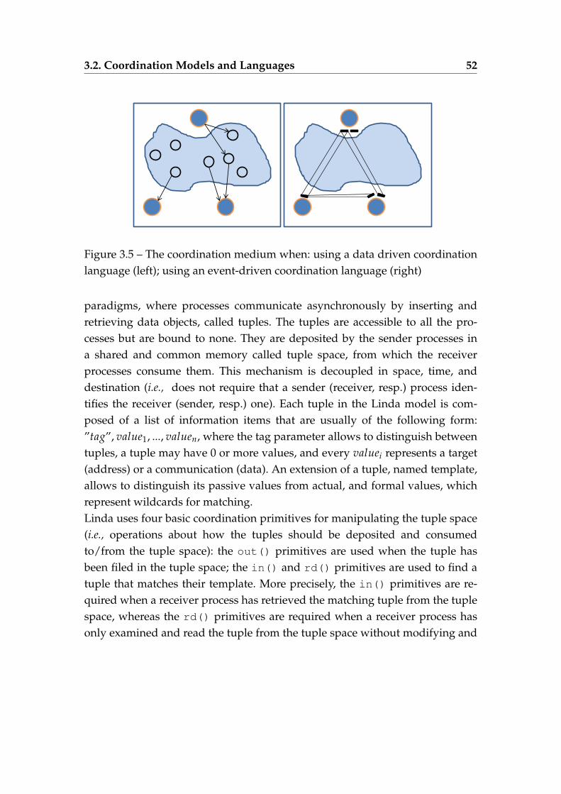
3.2. Coordination Models and Languages 52
Figure 3.5 – The coordination medium when: using a data driven coordinationlanguage (left); using an event-driven coordination language (right)
paradigms, where processes communicate asynchronously by inserting andretrieving data objects, called tuples. The tuples are accessible to all the pro-cesses but are bound to none. They are deposited by the sender processes ina shared and common memory called tuple space, from which the receiverprocesses consume them. This mechanism is decoupled in space, time, anddestination (i.e., does not require that a sender (receiver, resp.) process iden-tifies the receiver (sender, resp.) one). Each tuple in the Linda model is com-posed of a list of information items that are usually of the following form:”tag”, value1, ..., valuen, where the tag parameter allows to distinguish betweentuples, a tuple may have 0 or more values, and every valuei represents a target(address) or a communication (data). An extension of a tuple, named template,allows to distinguish its passive values from actual, and formal values, whichrepresent wildcards for matching.Linda uses four basic coordination primitives for manipulating the tuple space(i.e., operations about how the tuples should be deposited and consumedto/from the tuple space): the out() primitives are used when the tuple hasbeen filed in the tuple space; the in() and rd() primitives are used to find atuple that matches their template. More precisely, the in() primitives are re-quired when a receiver process has retrieved the matching tuple from the tuplespace, whereas the rd() primitives are required when a receiver process hasonly examined and read the tuple from the tuple space without modifying and
3.2. Coordination Models and Languages 53
removing it. When more than one tuple matches the template, only one is se-lected non-deterministically. Contrariwise, if there is no tuple to match the tem-plate, the process is not blocked. The eval() primitives are used when creatingan active tuple that turns into a passive one after its evaluation. The in() andrd() primitives are synchronous, whereas the out() and eval() primitivesare asynchronous.
Evaluation
The Linda coordination language is an intuitive language where all tuplesare accessed in a concurrently way by multiple processes, but it suffers from thefollowing limitations:
— the coordination medium, so-called tuple space, has a fixed behavior.Thereby, the coordination mechanisms cannot represent generic coordi-nation policies;
— the coordination medium is implemented as a shared and common mem-ory. Linda does not propose other solutions to implement it, especially inthe absence of shared memories;
— the Linda model does not support the process failures (i.e., it is not fault-tolerant);
In order to add more coordination features to coordinate more complex appli-cations, the Linda coordination model has been extended, by introducing newprimitives and several data spaces. In this regard, examples of extensions ofthe Linda paradigm include Objective Linda [86], PoliS [47], Shared Prolog [30],and TSpaces [139].
Other examples of data-driven coordination languages and models includeConcurrent Constraint Programming [29] and Opus [43].
3.2.2 Control- and Event-Driven Coordination Models and Languages
In the control driven coordination model, the coordination entities interactwith the external environment through events occurring on input/output ports.The control driven coordination model allows the coordination medium to ob-serve the states update and the events occurring within the ports of the co-
3.2. Coordination Models and Languages 54
ordination entities (see Figure 3.5, right). The coordination medium providesinformation, called coordination laws, about how the events should propagate.The event-driven coordination models and languages focus on the control flowmanagement and not on the information exchanged between coordination en-tities.
3.2.2.1 Manifold
In [15], the authors present Manifold, a strongly typed and exogenouscontrol- and event-driven coordination language based on the IWIM (IdealizedWorker Idealized Manager) model [12]. In the Manifold model, a set of featuresthat include composition and separation of concerns are introduced to manageasynchronous interactions between concurrent computations. Furthermore,the system is defined, topologically, by channeling components through theirexternal behavior, which presents the interfaces that a component may publish.Manifold defines four categories of primitives, which are processes, events,streams, and ports.
Processes
The processes have a set of input/output ports used to send and receive dataand are classified into two types: (1) the atomic processes can consume inputdata, compute, and produce output data through their ports. They are also ableto receive and generate events; (2) the coordination processes, called manifolds,coordinate the activities of some atomic processes. Each manifold is composedof two main parts:
— the head contains details, such as the process name and the names of itsports;
— the body is represented as a block that contains a finite number of states.Each state, in turn, is composed of a label that defines the condition al-lowing transitions to that state and a body that contains all the instruc-tions performed, in a non-deterministic order, upon transition to anotherstate. The main role of a state body is to generate event occurrences.
3.2. Coordination Models and Languages 55
Events
The events are raised by the components to enact a configuration. In Mani-fold, a configuration is defined by connections, disconnections, and rearrange-ment of the binding established between the components, which is necessary forthe context of dynamic applications. The manifold model also provides otherprocesses, named observer processes, and are in charge of observing event oc-currences. Once an event occurrence is observed by an observer process, it willbe put into its event memory. An observed event may be reacted by only oneobserver process. The Manifold language provides an event-driven state transi-tion mechanism as the only control mechanism.
Streams
The streams are communication links, connected to the ports, and used totransfer data in the form of sequences of bits from a source to its sink. There existfour basic types of stream, which are: BB (break-break) 1, BK (break-keep) 2, KB(keep-break) 3, and kk (keep-keep) 4.
Ports
The ports are used by the processes to exchange information. Indeed, eachprocess has a set of ports located at its boundary. Manifold provides three stan-dard ports (input, output, and error) defined for all instances of the process.
3.2.2.2 Reo
A channel-based exogenous coordination language, called Reo, was de-signed by F. Arbab in [14] as an extension of the Manifold language. Reo allowsto coordinate multiple entities, with supporting a high degree of synchrony.The entities may refer to processes, threads, agents, and software components.These entities, called component instances, execute at one or more locations.In the Reo model, each component is defined as black boxes and may have in-
1. the BB stream is used to break automatically a connection2. the BK stream is used to break the source connection and keep the sink connection3. the BK stream acts as the other way as the KB stream4. the kk stream is used to never disconnect
3.2. Coordination Models and Languages 56
put/output ports. The communication between the components is exogenousand established by a set of so-called connectors that coordinate their activities.Each connector may build up using a set of simpler connectors, which are com-posed of channels and nodes. A channel allows to flow data items by disposingof two types of ends: source end for accepting data into the channel and sink endfor putting data out of the channel. A channel in the Reo model can have onlyone of the two ends or both source and sink ends. Furthermore, Reo disposesof an open-ended number of channels, which allow developers to use theircustom semantics to integrate their own channels. Examples of Reo channelsinclude Sync channel, LossySync channel, SyncDrain channel, and FIFO
channel, which is an asynchronous channel. The Nodes are based on channelends and classified into three types: source, sink, or mixed, depending on thechannel ends. The two first types (e.g., source and sink nodes) allow the in-teraction of the channel with its environment. The Reo semantics is given byconstraint automata, where the transitions are labeled with synchronous portsand, if needed, data constraints on these ports.In [89], C. Krause presents some reconfiguration tasks in the context of Reoconnectors. In this work, the author supposes that both components and co-ordination layer are distributed. Thereby, the simpler connectors are hosted atdifferent locations (logical or physical machines). Furthermore, these connec-tors are supposed to connect to each other after knowing when and in whichway they will be reconfigured.
3.2.2.3 Evaluation
Reo is a highly exogenous and a powerful coordination language thatpresents an extension of the Manifold language. The Reo model is composedof a set of components that are regarded as black boxes. It is also based on aset of constraints that may be defined by channels and describe the connectorsbehaviors. Our focus is different here because we take into account the behaviorof the coordinated entities, which execute the reconfiguration process and aremodeled as LTSs. We use coordination requirements to describe the behavior ofa generated controller, which aims to orchestrate these entities and communi-cate with them asynchronously.
3.2. Coordination Models and Languages 57
3.2.3 Coordination Using Rule Agents and Decision Policies
3.2.3.1 Accord
In [93], the authors present the framework Accord, a component-basedmodel designed to build autonomous applications. These applications arebased on autonomous components that incorporate rule agents with autonomicproperties. Accord allows to coordinate several autonomic components usinghigh-level rules for their dynamic composition. The components are hosted ondistributed applications, which may include dynamism in the component statesand provided/required services. An Accord component is composed of the fol-lowing three elements:
— a functional port that describes the operations provided/required by thecomponent;
— a control port that controls the system. Indeed, it uses a set of sensors tomonitor the component state, a set of actuators to modify the componentstate and adapt it dynamically, and a set of constraints;
— an operational port that adds new rules, manages, and removes existingrules dynamically.
The rule agents configure, monitor, adapt the managed components, and en-sure the communication between them. To do this, they execute two types ofrules: behavior rules, which are used to describe the dynamic composition ofthe components (i.e., the component configuration) and the behavior of theirself-management, and interaction rules, which are used, with functional ports,to coordinate the interaction relationships between the components.The dynamic composition of an Accord system is based on multiple constraints.This includes, for instance, the composed components that interact together,how components interact together, and when components interact together. Thefirst constraint, i.e., composed components, is described by means of a work-flow graph where multiple reconfiguration tasks can be dynamically executed,e.g., adding, removing, and updating components or establishing, removing,and changing interactions in the workflows. This constraint is described usingbehavior rules, while the second and third constraints are described using in-teraction rules.
3.2. Coordination Models and Languages 58
The conflicting decisions between agents are solved with associating prioritieswith rules. Indeed, a rule that has a low priority should wait for locks held bythose having higher priorities. Moreover, several decision policies are handledby the agents in order to monitor the managed components. Agents are clas-sified into multiple categories, such as configuration, context, and compositionagents. Accord uses composition agents to support the centralized coordina-tion of workflows adaptation. It also supports the definition of decentralizedcoordination, which is described using Rudder, but it does not provide any de-centralized coordination model.
Evaluation
The Accord model is a component-based model based on rules and decisionpolicies and used to design autonomous applications in distributed environ-ments. However, we identified some limitations which are:
— Accord is based on interaction rules and not on connectors to describethe interaction between components, which prevent components takingindependent decisions;
— Accord uses a manual administration to evaluate and update the inter-action rules.
3.2.4 Coordination Using Utility-Functions
In [53], the authors present an approach based on multi-agent systems,which are autonomous decision makers that interact with each other to takecoherent decisions. The suggested approach provides a consistent control pol-icy for managing the agents (see Fig. 3.6). Furthermore, it introduces four majorparticipants: (1) the performance agents manage the performance by distribut-ing load among the active servers, while taking into account the QoS; (2) thepower agents, based on the Energy Management Tool (EMT) program, man-age the energy consumption of servers by adjusting the power of the servers;(3) the coordination agents, implemented in Java and hosted on a separateserver, have two main roles. It coordinates the two first agents (i.e., performanceagents and power agents) and also provides coherent control policies, such aspower-performance policy in order to manage a data center, while using a sys-
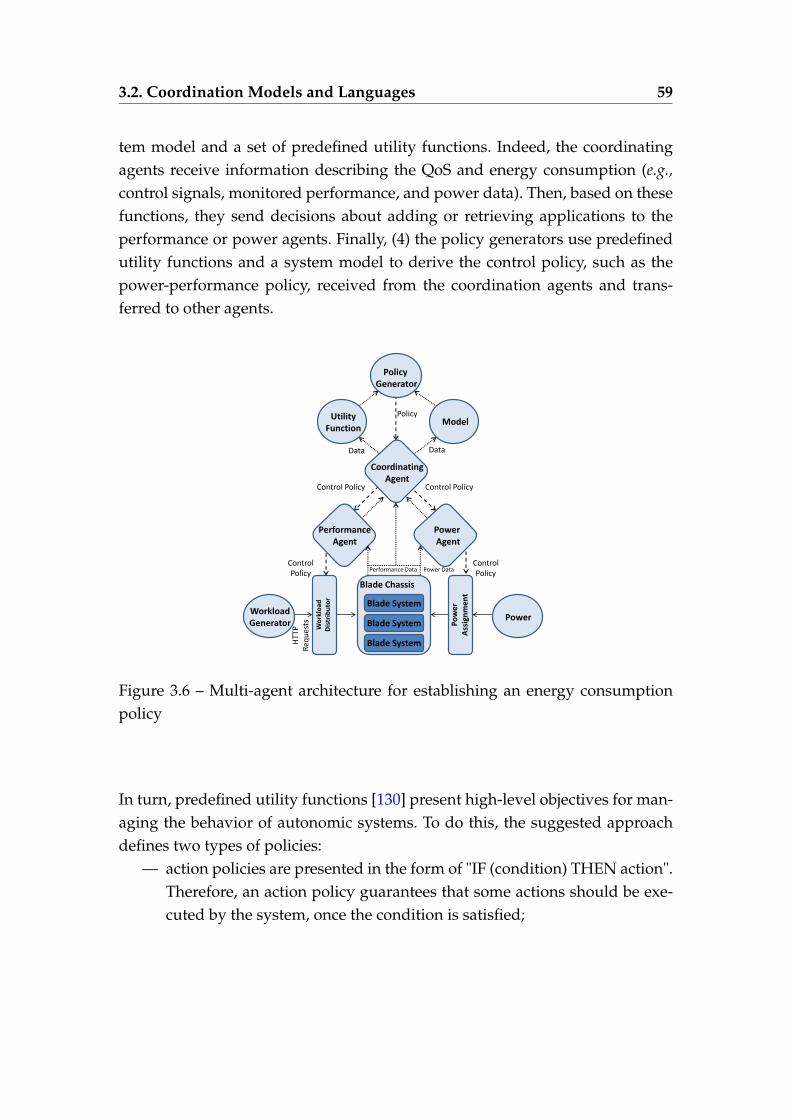
3.2. Coordination Models and Languages 59
tem model and a set of predefined utility functions. Indeed, the coordinatingagents receive information describing the QoS and energy consumption (e.g.,control signals, monitored performance, and power data). Then, based on thesefunctions, they send decisions about adding or retrieving applications to theperformance or power agents. Finally, (4) the policy generators use predefinedutility functions and a system model to derive the control policy, such as thepower-performance policy, received from the coordination agents and trans-ferred to other agents.
Policy Generator
Model Utility
Function
Coordinating Agent
Power Agent
Blade System
Blade System
Blade System
Blade Chassis
Po
we
r A
ssig
nm
en
t
Wo
rklo
ad
Dis
trib
uto
r
Workload Generator
Power
Policy
Data Data
Control Policy Control Policy
Control Policy
Control Policy
Power Data Performance Data
HT
TP
Req
ues
ts
Performance Agent
Figure 3.6 – Multi-agent architecture for establishing an energy consumptionpolicy
In turn, predefined utility functions [130] present high-level objectives for man-aging the behavior of autonomic systems. To do this, the suggested approachdefines two types of policies:
— action policies are presented in the form of "IF (condition) THEN action".Therefore, an action policy guarantees that some actions should be exe-cuted by the system, once the condition is satisfied;
3.2. Coordination Models and Languages 60
— goal policies define the high-level objectives of the system. They aretranslated, using utility functions, into specific actions to the possibleconditions. To establish a translation, the utility functions allow to map acurrent system state to another preferred state.
Evaluation
We observe that this approach, based on multi-agent systems used as au-tonomous decision makers, focuses on a specific application domain and itsresults are difficult reusable in other contexts.
3.2.5 Coordination Using Shared Knowledge
In [111], the authors propose a generic integration model that focuses, first,on categorizing autonomic loops in terms of reciprocal interference using theirreciprocal interferences. The control loops are implemented using the MAPE-K reference model (see Fig. 2.4.1). This generic model, based on actions andevents of inter-loop, can be used to manage the synchronization and coordina-tion of multiple control loops. The control loops communicate with one anotherthrough a shared knowledge-based synchronization pattern. This knowledge iscomposed of two parts:
— private knowledge, which contains necessary internal information askedby a set of internal control loop functions;
— public knowledge, which provides information shared among controlloops. When one of these loops needs to modify any information, thisknowledge must be synchronized. When multiple loops need to modifythe same information at the same time, error-prone situations may oc-cur. To avoid this problem, the authors propose that only the owner ofthe public knowledge should modify it directly, by using a control loopcoordination protocol.
Before explaining the control loop coordination protocol proposed by this ap-proach, let us clarify the difference between an event and an action used by theintegration model.
— an action can be used in three cases: (i) when executing a decision onthe managed system, (ii) when notifying another control loop (i.e., inter-
3.2. Coordination Models and Languages 61
loop), and (iii) when launching a step within a control loop (i.e., intra-loop). In the two first cases, the action is executed by the execute function(the fourth function of the MAPE reference model). Contrariwise, in thethird case, it may be executed by the monitor function to launch the ana-lyze function, or by the analyze function to launch the plan function, orby the plan function to launch the execute function. An intra-loop actionis used to change public knowledge or to invoke handler actions.
— an event has one of the two major types: endogenous event that has themanaged system as a source and exogenous event that has another con-trol loop as a source.
This approach proposes a coordination protocol, which aims to coordinatemultiple control loops. To do this, the execute function of a control loop asksevery loop, with which it must take globally coherent decisions, services beforeexecuting. Then, it waits for the answers. This mechanism is ensured by trigger-ing an inter-loop event, which will be detected by the monitor function of thesecond control loop, in order to start it. At the same time, it creates a handlerthat has all the actions needed to be executed after the reception of the answers.Once the second control loop makes its responses, an inter-loop event will besent to the first control loop.
Evaluation
The suggested protocol was applied to a scenario in the context of cloudcomputing. The scenario is composed of multiple self-adaptive applicationsthat communicate with a shared self-adaptive infrastructure. Indeed, the pri-mary role of the coordination protocol in this context is, on the one hand, max-imize the Quality of Service at the applications while minimizing costs, and onthe other hand to optimize the utilization rate at the common infrastructure. Themodel was evaluated through simulation-based experiments. However, this ap-proach still has some limitations, which are:
— the model is restricted to a controller loop. It is not clear if the same modelcan be used for other entities, such as agents, processes, and softwarecomponents;
— the decisions taken by every control loop must take into account infor-mation provided by other loops. Therefore, when several loops control
3.3. Controller Synthesis Techniques 62
the same application, every one of these loops cannot execute before ask-ing services from the other loops and waiting for all their answers. Thisslows the response time of the loop;
— in the cloud computing scenarios, multiple unexpected events can oc-cur at each time of the runtime. This approach does not explain howthe shared knowledge takes into consideration the changes that have oc-curred.
Our focus is quite different here because we work on controller synthesis tech-niques whose goal is to control other entities where components are modeledas LTSs and communicate asynchronously. Moreover, our techniques are basedon a set of coordination requirements that take into account all the changes thatcan occur in the system.
3.3 Controller Synthesis Techniques
3.3.1 Original Theory for Controller Synthesis Techniques
We start this section with a short overview of the original theory for con-troller synthesis. The approach was originally introduced by Ramadge andWonham in 1987 [137, 119] in order to resolve problems of Discrete Event Sys-tems (DESs), which contains discrete states, where the controller switches be-tween them by means of events. The approach is called Discrete Controller Syn-thesis (DCS) and aims to control the logical behavior of discrete event systemsoriginally described using programming languages for programmable logiccontrollers (PLCs).The controller synthesis technique focuses on models of entities to be controlledand a set of properties to be satisfied by the models to design a controller. Thecontroller has an impact on the system behavior in order to avoid incorrect be-havior specified by the properties. To do this, the controller observes all thesystem events and enforces it to respect the properties, which are regarded asconstraints imposed by the system. They can describe the relationship betweenstates in the models or incorporate temporal aspects. In the context of DESs,
3.3. Controller Synthesis Techniques 63
the controller synthesis is applied to ensure the properties verifying the systemstate. The controller must take coherent decisions, even in the context of com-plex systems (e.g., decentralized systems, system composed of multiple subsys-tems deployed on distant sites) or in the presence of structural constraints (e.g.,communication constraints).In [137], the authors present a controllable language as a solution for the super-visory of hybrid control systems. This work gives an approach that generatescontrollers from a particular system called plant and designed as a finite au-tomaton.[119] proposes a supervisor synthesis algorithm, which allows the automaticgeneration of a controller (represented by a language C) from a given plant,modeled by a language P as finite state machines, and a specification language.The language P defines an alphabet of events. The generated controller, calledmaximally permissive, may dynamically enable/disable some events, namedcontrollable events. It also permits all possible legal executions and must satisfythe properties (e.g., safety and liveness properties) and minimal restrictivenessobjectives required in the specification. This suggested synthesis approach isbased on a classical two-person game approach which: (1) formally synthesizea controller from a representation of all possible behaviors of the system repre-sented as state machines or Petri nets, or STS. (2) Then, check if the monitoredsystem verifies given properties that may describe situations to reach or/andsituations to avoid. These approaches can be characterized as restrictive becausethey directly influence and impact the controlled system. The events issued bythe system are broadly divided into two categories: controllable events, whichmay be prevented by the controller, and non-controllable events, which cannotbe disabled by the controller. For a detailed overview of supervisory controltheory, the reader is referred to [39, 135].This synthesis controller approach is based on the supervisor construction con-cept and regarded as a modular synthesis technique, which decomposes a com-plex discrete event system (DES) to a set of independent components, definesalgebra of the DES and also of the corresponding supervisors. Therefore, thedesired supervisor is synthesized as a product system. The interaction betweenthe components is modeled as control constraints. The approach aims at control-ling the components and also satisfying constraints specified using controlled
3.3. Controller Synthesis Techniques 64
languages. Indeed, the supervisor tries to respect the constraints by inhibitingsome behaviors to provide the correct behavior of the originally uncontrolledDES.
Evaluation
The authors introduce a solution that is interesting from a theoretical pointof view. They propose a polynomial-time algorithm that allows to respect theconstraints and ensure a large set of correct and optimal behaviors of the origi-nally uncontrolled systems that are modeled as finite state automata. However,this solution has some drawbacks. It is very difficult to implement and does nottackle the state space explosion problems. Therefore, it does not easily scale toreal systems where the generated controller may have an enormous number ofstates even for small systems. For this, it has been extended by control theo-retic ideas (e.g., controllability, modular, and decentralized control) and severalalgorithms have been improved in numerous ways [136].
3.3.2 Modular Discrete Controller Synthesis Using Synchronous Lan-guage BZR
Other syntheses techniques are based on synchronous languages, such asBZR, that provide formal methods for the specification of reactive systems, fea-ture verification tools, and code generation executable from the specification.
3.3.2.1 Synchronous Synthesis Techniques for Coordinating Adaptive and Reconfig-urable Systems
In [55], Delaval et Al. present an extension of the Heptagon/BZR language, areactive programming language, with behavioral contract constructs. This pro-gramming language is used to specify discrete control part of systems with au-tomata. The authors introduce an approach based on contract enforcement andcomponents abstraction to apply a modular discrete controller synthesis (DCS)on synchronous programs. Namely, each program is represented as a composi-tion of nodes, which are the abstraction level used in BZR in order to achieve a
3.3. Controller Synthesis Techniques 65
modular application of the DCS. Each node is compiled in an independent wayand has a contract with itself. Indeed, the DCS synthesizes a set of reconfigura-tion controllers for the program. It computes automatically, for each abstraction,a controller. Then, all the controllers are recomposed to generate a controller forthe initial program. The generated controller must satisfy properties given asobjective for the co-execution of the initial program. This approach stems fromboth control of discrete event system and control theory. The authors integrateit in a high-level programming language combining data-flow and automatamachines, named BZR. This synchronous language defines reactive systems us-ing generalized Moore machines. In turn, BZR has been used in several works(e.g., component based software, the coordination of administration loops). Thisapproach is applied to adaptive and reconfigurable systems, such as embeddedsystems. It was implemented in the Sigali tool [101], a symbolic model checkerand synthesis controller that uses as input a global view of the system.
3.3.2.2 Synchronous Synthesis Techniques for Coordinating Autonomic Managers
In other recent works [54, 74, 75], Delaval, Rutten, Gueye et Al. propose sometechniques based on synchronous discrete controller synthesis for coordinatingautonomic managers, such as self-repair and self-sizing managers. The commu-nication between the generated controller and managers is synchronous anduses the reactive and synchronous language BZR. BZR contains a behavioralcontract mechanisms and dynamic temporal properties, which are enforced byan automatically build controller. The use of BZR is based on the notion of con-tract in system modeling. The contract is composed of three parts: (1) enforceis the part where the properties are declared as control objectives, (2) with isthe part where some local controllable variables are added when the model thatdescribes the system operation does not respect the properties, and (3) assumeis the part that contains relevant properties of the run-time environment. Thisinformation is taken into account when synthesizing the control logic.
3.3. Controller Synthesis Techniques 66
3.3.2.3 Evaluation
Compared to monolithic synthesis, this approach has the advantage ofbreaking down the synthesis computation cost. But, it also has some drawbackswhich are:
— BZR cannot impose a specific order between requirements.— this approach allows the designers to describe the constraints that must
be ensured at runtime to compute the corresponding controller. How-ever, the approach does not explain how the designers ensure that theconstraints do not lead to an error-prone expression;
— the computed controller describes all the possible behaviors, which canbe allowed in every step. The implementation of the controller needs adecision system that chooses only one of them;
— this approach does not provide additional information (e.g., the falseconstraint on the contracts) to the designers when the controller synthesisfails;
— this approach does not propose solutions to deal with the synthesis fail-ure.
3.3.3 Synthesis of Decentralised Supervisors for Distributed Adap-tive Systems
A decentralized supervisory control approach for synchronous reactive sys-tems is presented by Belhaj et Al. in [128, 127]. This work is based on distributedadaptive systems modeled through adaptation managers as synchronous reac-tive systems. The reactive systems, based on a set of events and states, are mod-eled as finite state machines, so-called Moore machines. Each machine containsa set of input/output signals and transition guards. The adaptation managersinteract with the environment and continuously react to input signals by ma-nipulating them and producing output signals. It is worth noting that the adap-tation managers read simultaneously the values of input signals and computeinstantly the output signals. This approach is based on existing techniques fordiscrete controller synthesis, to control the decentralized reactive systems. Each
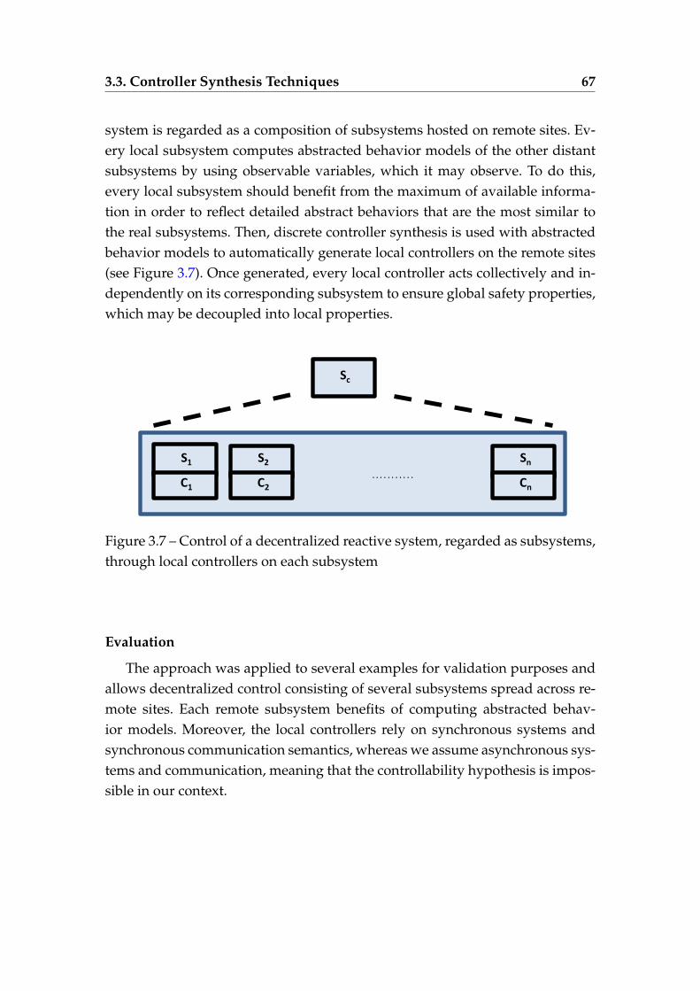
3.3. Controller Synthesis Techniques 67
system is regarded as a composition of subsystems hosted on remote sites. Ev-ery local subsystem computes abstracted behavior models of the other distantsubsystems by using observable variables, which it may observe. To do this,every local subsystem should benefit from the maximum of available informa-tion in order to reflect detailed abstract behaviors that are the most similar tothe real subsystems. Then, discrete controller synthesis is used with abstractedbehavior models to automatically generate local controllers on the remote sites(see Figure 3.7). Once generated, every local controller acts collectively and in-dependently on its corresponding subsystem to ensure global safety properties,which may be decoupled into local properties.
S1
C1
S2
C2
. . . . . . . . . . .
Sc
Sn
Cn
Figure 3.7 – Control of a decentralized reactive system, regarded as subsystems,through local controllers on each subsystem
Evaluation
The approach was applied to several examples for validation purposes andallows decentralized control consisting of several subsystems spread across re-mote sites. Each remote subsystem benefits of computing abstracted behav-ior models. Moreover, the local controllers rely on synchronous systems andsynchronous communication semantics, whereas we assume asynchronous sys-tems and communication, meaning that the controllability hypothesis is impos-sible in our context.
3.3. Controller Synthesis Techniques 68
3.3.4 A Framework for the Coordination of Multiple Autonomic Man-agers in Cloud Environments
In [110], Oliveira et Al. present a framework for the coordination of multipledependent autonomic managers in the cloud computing context. Managers arebroadly classified in two categories: application-related managers that manageapplications on the SaaS layer and infrastructure-related managers which man-age the IaaS layer. The two categories use a protocol based on inter-managerevents and actions and synchronization mechanisms for coordinating thesemanagers. The suggested framework defines how the managers must commu-nicate using these actions and events. The authors also propose some analyticalmodels that are based on constraint programming and allow one to equip themanagers with self-optimization capabilities.
Evaluation
This approach focuses on quality of service whereas our focus was on be-havioral and functional aspects of the system execution.
3.3.5 Summary
We have presented a review of different controller synthesis techniques,which use languages and models used for coordination purposes (see Sec-tion 3.2). The coordination techniques use constraints, shared information, orevent-driven coordination models and languages for coordinating entities. Inour approach, we use constraints to describe the controller that we want to gen-erate. We observe that most controller synthesis techniques are stemming fromsynchronous languages, whereas our approach assumes that communication isachieved asynchronously. Finally, we observe that not all these approaches useverification techniques to verify the control behavior.
Table 3.2 – Comparison between controller synthesis techniquesSynchronous Asynchronous Verification Coordination
Ramadge,Wonham
3 7 3 constraints
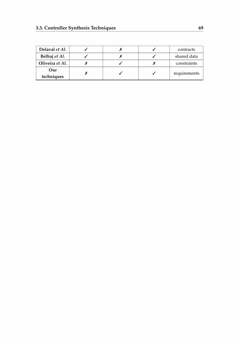
3.3. Controller Synthesis Techniques 69
Delaval et Al. 3 7 3 contracts
Belhaj et Al. 3 7 3 shared data
Oliveira et Al. 7 3 7 constraintsOur
techniques7 3 3 requirements
4Dynamic Management Protocol for
Cloud Applications
" There is a tremendous difference between a computing system that works and onethat works well. "
K. Birman, R.V. Renesse, and W. Vogels [23]
Contents
4.1 Reconfiguration Protocol . . . . . . . . . . . . . . . . . . . . . . 73
4.1.1 Application Model . . . . . . . . . . . . . . . . . . . . . 73
4.1.2 Architectural Invariants . . . . . . . . . . . . . . . . . . 75
4.1.3 Protocol Participants . . . . . . . . . . . . . . . . . . . . 76
4.1.4 Protocol Description . . . . . . . . . . . . . . . . . . . . 78
71
4.1.5 Example of a Component Removal/Addition and VMFailure . . . . . . . . . . . . . . . . . . . . . . . . . . . . 88
4.2 Protocol Specification and Verification . . . . . . . . . . . . . . . 93
4.2.1 Protocol Specification . . . . . . . . . . . . . . . . . . . . 94
4.2.2 Protocol Verification . . . . . . . . . . . . . . . . . . . . 99
4.3 Experiments . . . . . . . . . . . . . . . . . . . . . . . . . . . . . 102
4.4 Problems Found and Corrected . . . . . . . . . . . . . . . . . . 104
4.5 Protocol Implementation . . . . . . . . . . . . . . . . . . . . . . 106
4.6 Conclusion . . . . . . . . . . . . . . . . . . . . . . . . . . . . . . 108
72
WE present in this chapter a novel protocol, which targets automatic de-ployment and (re)configuration of cloud applications. These applica-
tions are intricate distributed applications composed of virtual machines (VMs)running a set of interconnected software components. A reconfiguration man-ager guides the reconfiguration tasks by instantiating new VMs or destroy-ing/repairing existing VMs. This reconfiguration manager may also execute ar-chitectural changes to the application by adding new components or removingexisting components hosted on specific VMs. After the creation of new compo-nents due to the instantiation of a new VM or to components addition requests,the protocol is in charge of starting all components in the correct order accord-ing to the architectural dependencies. Each VM embeds a local reconfigurationagent (agent for short in the rest of this dissertation). Each agent interacts withthe other remote agents. For each component, the VM agent tries to satisfy its re-quired services by connecting them to their providers in order to finally start thecomponent. The component cannot be started before the components on whichit depends for mandatory imports. The supplier of the service can be hosted onthe same VM or on another VM. When an agent receives a component removalor a VM destruction request from the reconfiguration manager, it tries to stopand unbind all the components hosted on the VM. A component cannot stopbefore all partner components connected to it have unbound themselves. To ex-change messages and bind/start/unbind/stop components, the VMs commu-nicate together through a publish-subscribe messaging system. The protocol isfault-tolerant in the sense that it enables the detection of VM failures that occurto a running application and repair them. When a VM failure occurs, the proto-col notifies the VMs that are impacted. The protocol supports multiple failures.It always succeeds in finally reconfiguring the application at hand and stop-ping/starting all components. Our management protocol implies a high degreeof parallelism. Hence, we decided to use formal methods and tools to specify,verify the protocol, and ensure that it preserves important architectural invari-ants (e.g., a started component cannot be connected to a stopped component) and satis-fies certain properties (e.g., each VM failure is followed by a new creation of that VM).The protocol was specified using the specification language LOTOS NT (LNT)and verified with the CADP verification toolbox. For verification purposes, weused 600 hand-crafted examples (application models and reconfiguration sce-
4.1. Reconfiguration Protocol 73
narios). For each example, we generated the Labelled Transition System (LTS)from the LNT specification, and we checked on them about 40 properties thatmust be respected by the protocol during its application. To do so, we used themodel checking tools available in the CADP toolbox. These formal techniquesand tools helped us to improve the protocol by (i) identifying two importantissues that we detected, and by then (ii) correcting them in the correspondingJava implementation which was written at the same time as the specification byanother partner from the OpenCloudware project.
4.1 Reconfiguration Protocol
This section successively presents the application model, the protocol partic-ipants (i.e., the reconfiguration manager, the publish-subscribe messaging sys-tem, and the reconfiguration agents), the protocol itself including the differentpossible reconfiguration operations, and an overview of the Java implementa-tion.
4.1.1 Application Model
In this section, we first introduce an abstraction of the model, which is suf-ficient for describing the protocol principles. The real model exhibits more de-tails, such as port numbers, URLs, and other implementation details. The modelwe use here is used for reconfiguring distributed cloud application. Its primaryrole is to keep track of the VMs and components currently deployed in a cloudapplication.
Distributed cloud applications are composed of a set of interconnectedsoftware components hosted on different virtual machines (VMs). Each oneof these components is willing to provide services via exports and/or requireservices via imports. Ports are typed and matched when they share the sametype. In fact, each import requires an export with the same type for beingsatisfied. An export can provide its service to several components and canthus be connected to several imports. An import should be connected to an
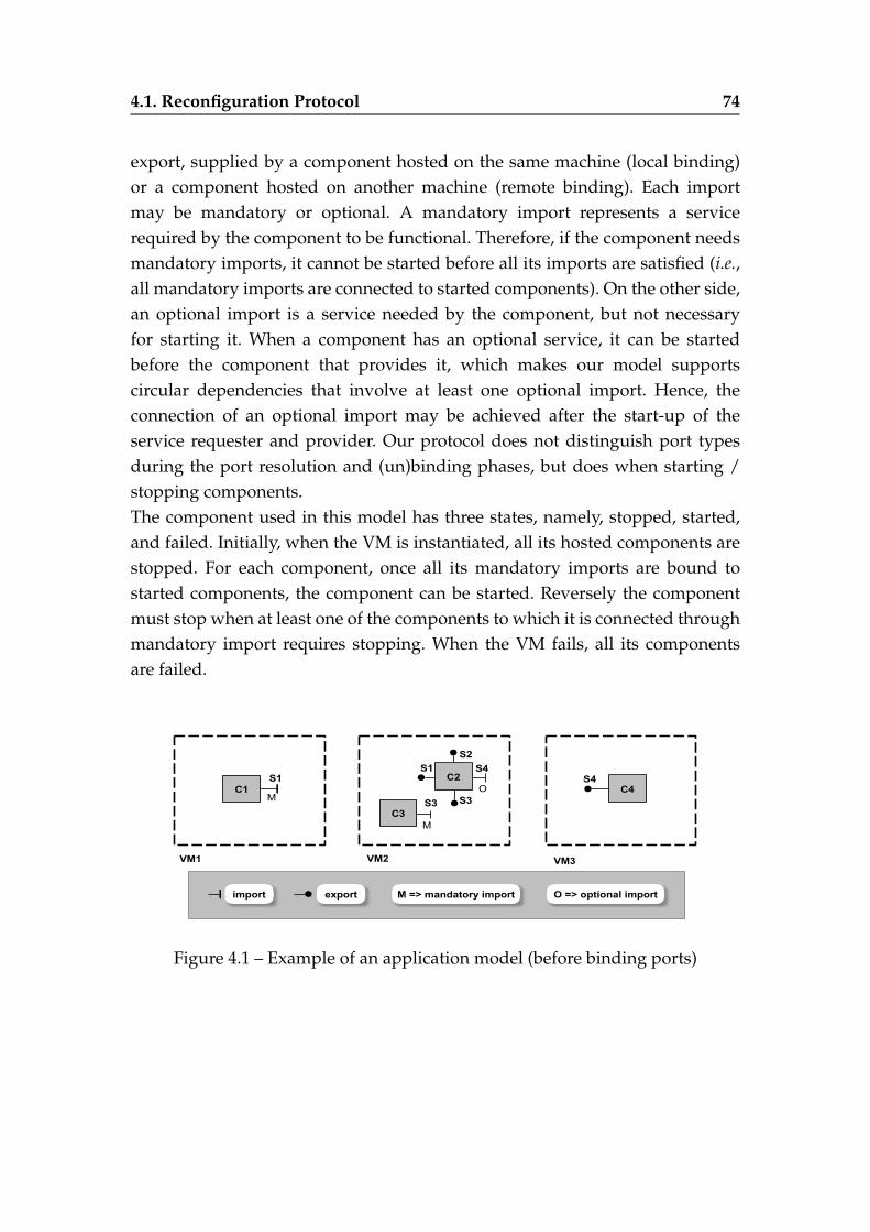
4.1. Reconfiguration Protocol 74
export, supplied by a component hosted on the same machine (local binding)or a component hosted on another machine (remote binding). Each importmay be mandatory or optional. A mandatory import represents a servicerequired by the component to be functional. Therefore, if the component needsmandatory imports, it cannot be started before all its imports are satisfied (i.e.,all mandatory imports are connected to started components). On the other side,an optional import is a service needed by the component, but not necessaryfor starting it. When a component has an optional service, it can be startedbefore the component that provides it, which makes our model supportscircular dependencies that involve at least one optional import. Hence, theconnection of an optional import may be achieved after the start-up of theservice requester and provider. Our protocol does not distinguish port typesduring the port resolution and (un)binding phases, but does when starting /stopping components.The component used in this model has three states, namely, stopped, started,and failed. Initially, when the VM is instantiated, all its hosted components arestopped. For each component, once all its mandatory imports are bound tostarted components, the component can be started. Reversely the componentmust stop when at least one of the components to which it is connected throughmandatory import requires stopping. When the VM fails, all its componentsare failed.
Figure 4.1 – Example of an application model (before binding ports)
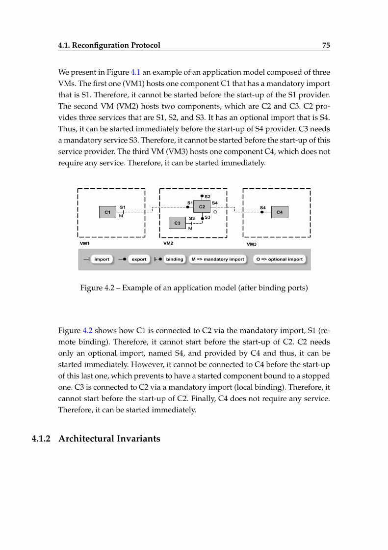
4.1. Reconfiguration Protocol 75
We present in Figure 4.1 an example of an application model composed of threeVMs. The first one (VM1) hosts one component C1 that has a mandatory importthat is S1. Therefore, it cannot be started before the start-up of the S1 provider.The second VM (VM2) hosts two components, which are C2 and C3. C2 pro-vides three services that are S1, S2, and S3. It has an optional import that is S4.Thus, it can be started immediately before the start-up of S4 provider. C3 needsa mandatory service S3. Therefore, it cannot be started before the start-up of thisservice provider. The third VM (VM3) hosts one component C4, which does notrequire any service. Therefore, it can be started immediately.
Figure 4.2 – Example of an application model (after binding ports)
Figure 4.2 shows how C1 is connected to C2 via the mandatory import, S1 (re-mote binding). Therefore, it cannot start before the start-up of C2. C2 needsonly an optional import, named S4, and provided by C4 and thus, it can bestarted immediately. However, it cannot be connected to C4 before the start-upof this last one, which prevents to have a started component bound to a stoppedone. C3 is connected to C2 via a mandatory import (local binding). Therefore, itcannot start before the start-up of C2. Finally, C4 does not require any service.Therefore, it can be started immediately.
4.1.2 Architectural Invariants
4.1. Reconfiguration Protocol 76
As stated before, the architectural invariants must hold for any reconfigu-ration of distributed cloud applications. We present below the set of invariantsthat we defined to preserve the application consistency.
— there are no circular dependencies through mandatory imports;— a component cannot be started before the component it depends on for
mandatory imports;— a started component cannot be connected to a stopped component;— there is no component connected to failed or removed components.
The satisfaction of these invariants during the application execution is an im-portant goal in the context of cloud applications.
4.1.3 Protocol Participants
The management protocol consists of three following participants: the recon-figuration manager (RM), virtual machines (VMs), and the publish-subscribecommunication messaging system (PS), depicted in Figure 4.3.
4.1.3.1 Reconfiguration Manager (RM)
The RM is responsible for reconfiguring the application. It is used to per-form two main roles: (1) it guides the application reconfiguration by succes-sively sending reconfiguration operations, which are described in a reconfigu-ration scenario and indicate changes to perform on the application. Namely, thereconfiguration operations are instantiating a new VM, destroying an existingVM, repaired a failed VM, adding a new component, and removing an exist-ing component. (2) The RM is also in charge of repairing each VM failure bycreating a new instance of the failed VM when a failure is detected.
4.1.3.2 Virtual Machine (VM)
Each VM is associated with a reconfiguration agent (agent for short in therest of this dissertation). Each agent interacts with the other participants and ef-
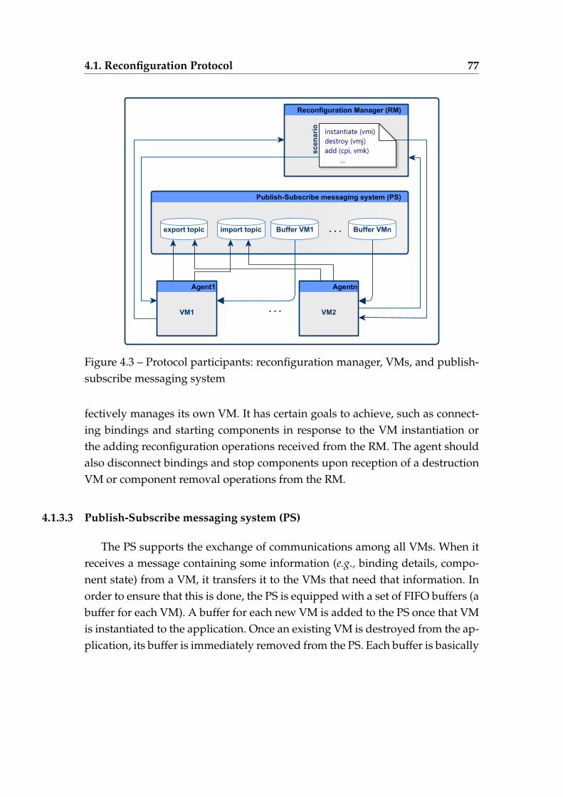
4.1. Reconfiguration Protocol 77
Figure 4.3 – Protocol participants: reconfiguration manager, VMs, and publish-subscribe messaging system
fectively manages its own VM. It has certain goals to achieve, such as connect-ing bindings and starting components in response to the VM instantiation orthe adding reconfiguration operations received from the RM. The agent shouldalso disconnect bindings and stop components upon reception of a destructionVM or component removal operations from the RM.
4.1.3.3 Publish-Subscribe messaging system (PS)
The PS supports the exchange of communications among all VMs. When itreceives a message containing some information (e.g., binding details, compo-nent state) from a VM, it transfers it to the VMs that need that information. Inorder to ensure that this is done, the PS is equipped with a set of FIFO buffers (abuffer for each VM). A buffer for each new VM is added to the PS once that VMis instantiated to the application. Once an existing VM is destroyed from the ap-plication, its buffer is immediately removed from the PS. Each buffer is basically
4.1. Reconfiguration Protocol 78
used to store the messages that are sent to its VM and that can contain usefulinformation for the start-up or shutdown. We assume that transferred messagesare never lost during this communication. The PS is also equipped with twotopics 1: (i) an export topic where a component subscribes its imports and pub-lishes its exports, and (ii) an import topic where a component subscribes itsexports and publishes its imports. We show in Section 4.1.4.1 why this doublesubscription/publication is required.
4.1.4 Protocol Description
We explain in this section how the protocol works in order to perform itsmain goal, which is to reconfigure dynamically distributed cloud applicationsby instantiating new VMs/destroying existing VMs, adding a new componentto an existing VM/removing a component from its hosting VM, and repairingfailures. We detail how it works in each of these situations.
4.1.4.1 Start-up
The first goal of an agent is to start all the local components when instan-tiating a new VM or when adding a component to an existing VM. The agentbehavior, illustrated in Figure 4.4, aims to start each component having manda-tory and/or optional imports. First, when the agent receives an add componentrequest from the RM (Ê), it checks the presence of exports and import for thatcomponent. If the component provides services, it subscribes to the import topicand then publishes each of these services to the export topic (Ë). Then, the agentreacts following the list of imports.
No import
If the component does not have any import, it starts immediately (Ð) andthen, sends a started message to the PS (Ñ) to notify it about its new state that
1. A topic is a logical channel where messages are published and subscribers to a topic re-ceive messages published on that topic.
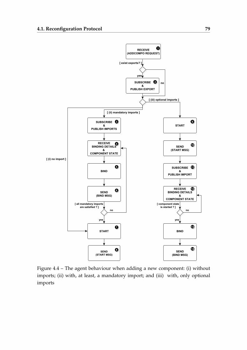
4.1. Reconfiguration Protocol 79
Figure 4.4 – The agent behaviour when adding a new component: (i) withoutimports; (ii) with, at least, a mandatory import; and (iii) with, only optionalimports
4.1. Reconfiguration Protocol 80
is started.
Mandatory import
To be functional, the component expects that all its mandatory imports willbe connected to exports with the same types provided by started components.The service provider can be a component hosted on the same VM (local) or onanother VM (remote). For each mandatory import, the component subscribes tothe export topic and then publishes the import to the import topic (Ì). When thePS receives the publication message, it checks the import topic. If it does not findany provider for the service, that message is deleted. Otherwise, if the PS findsmore than one service provider, it picks one randomly. Then, it sends a messagecontaining binding details and provider state to the component. The importcan connect to the service provider (Î) upon reception of that message fromthe PS (Í). Finally, the agent sends a binding message (Ï) to the PS informing itabout the connection to the service provider. Every time the component receivesa message containing binding details/and or component states, it verifies theprovider state and if all mandatory imports are connected. If it finds that all itsmandatory imports are connected to started components, the VM agent startsthe component (Ð) and then, sends a started message to the PS notifying it aboutits new state that is started (Ñ).
Optional import
When the component has only optional imports, it can immediately starteven if these imports are not satisfied (Ò) and send a started message to the PS( 10 ). Then, for each optional import, it subscribes to the export topic and pub-lishes the import to the import topic ( 11 ). Upon reception of a message withbinding details and component state ( 12 ), the import binds ( 13 ) to this compati-ble export and then sends a binding message ( 14 ) only if the component state isstarted.
When the component has several optional imports and at least one manda-tory import, it cannot start before satisfying the mandatory import (bind it tothe service provider and the partner component has been started).
When the RM guides the application reconfiguration by instantiating a newVM, a buffer for this VM is added to the list of buffers contained in the PS.
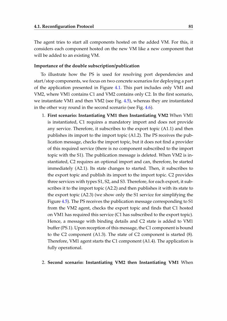
4.1. Reconfiguration Protocol 81
The agent tries to start all components hosted on the added VM. For this, itconsiders each component hosted on the new VM like a new component thatwill be added to an existing VM.
Importance of the double subscription/publication
To illustrate how the PS is used for resolving port dependencies andstart/stop components, we focus on two concrete scenarios for deploying a partof the application presented in Figure 4.1. This part includes only VM1 andVM2, where VM1 contains C1 and VM2 contains only C2. In the first scenario,we instantiate VM1 and then VM2 (see Fig. 4.5), whereas they are instantiatedin the other way round in the second scenario (see Fig. 4.6).
1. First scenario: Instantiating VM1 then Instantiating VM2 When VM1is instantiated, C1 requires a mandatory import and does not provideany service. Therefore, it subscribes to the export topic (A1.1) and thenpublishes its import to the import topic (A1.2). The PS receives the pub-lication message, checks the import topic, but it does not find a providerof this required service (there is no component subscribed to the importtopic with the S1). The publication message is deleted. When VM2 is in-stantiated, C2 requires an optional import and can, therefore, be startedimmediately (A2.1). Its state changes to started. Then, it subscribes tothe export topic and publish its import to the import topic. C2 providesthree services with types S1, S2, and S3. Therefore, for each export, it sub-scribes it to the import topic (A2.2) and then publishes it with its state tothe export topic (A2.3) (we show only the S1 service for simplifying theFigure 4.5). The PS receives the publication message corresponding to S1from the VM2 agent, checks the export topic and finds that C1 hostedon VM1 has required this service (C1 has subscribed to the export topic).Hence, a message with binding details and C2 state is added to VM1buffer (PS.1). Upon reception of this message, the C1 component is boundto the C2 component (A1.3). The state of C2 component is started (8).Therefore, VM1 agent starts the C1 component (A1.4). The application isfully operational.
2. Second scenario: Instantiating VM2 then Instantiating VM1 When
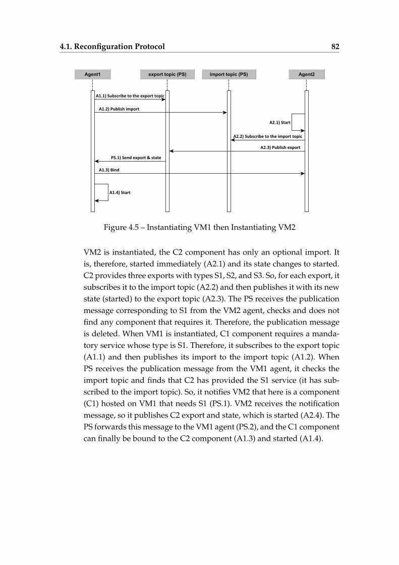
4.1. Reconfiguration Protocol 82
Figure 4.5 – Instantiating VM1 then Instantiating VM2
VM2 is instantiated, the C2 component has only an optional import. Itis, therefore, started immediately (A2.1) and its state changes to started.C2 provides three exports with types S1, S2, and S3. So, for each export, itsubscribes it to the import topic (A2.2) and then publishes it with its newstate (started) to the export topic (A2.3). The PS receives the publicationmessage corresponding to S1 from the VM2 agent, checks and does notfind any component that requires it. Therefore, the publication messageis deleted. When VM1 is instantiated, C1 component requires a manda-tory service whose type is S1. Therefore, it subscribes to the export topic(A1.1) and then publishes its import to the import topic (A1.2). WhenPS receives the publication message from the VM1 agent, it checks theimport topic and finds that C2 has provided the S1 service (it has sub-scribed to the import topic). So, it notifies VM2 that here is a component(C1) hosted on VM1 that needs S1 (PS.1). VM2 receives the notificationmessage, so it publishes C2 export and state, which is started (A2.4). ThePS forwards this message to the VM1 agent (PS.2), and the C1 componentcan finally be bound to the C2 component (A1.3) and started (A1.4).
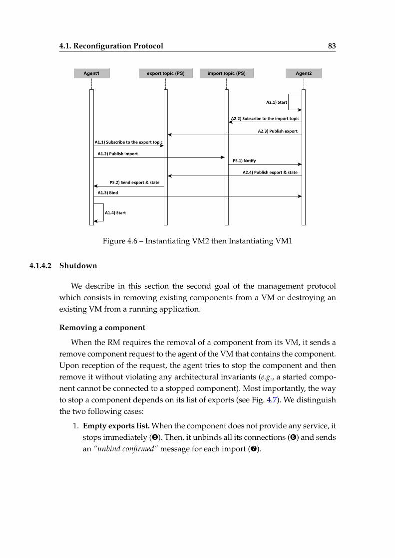
4.1. Reconfiguration Protocol 83
Figure 4.6 – Instantiating VM2 then Instantiating VM1
4.1.4.2 Shutdown
We describe in this section the second goal of the management protocolwhich consists in removing existing components from a VM or destroying anexisting VM from a running application.
Removing a component
When the RM requires the removal of a component from its VM, it sends aremove component request to the agent of the VM that contains the component.Upon reception of the request, the agent tries to stop the component and thenremove it without violating any architectural invariants (e.g., a started compo-nent cannot be connected to a stopped component). Most importantly, the wayto stop a component depends on its list of exports (see Fig. 4.7). We distinguishthe two following cases:
1. Empty exports list. When the component does not provide any service, itstops immediately (Î). Then, it unbinds all its connections (Ï) and sendsan “unbind confirmed" message for each import (Ð).
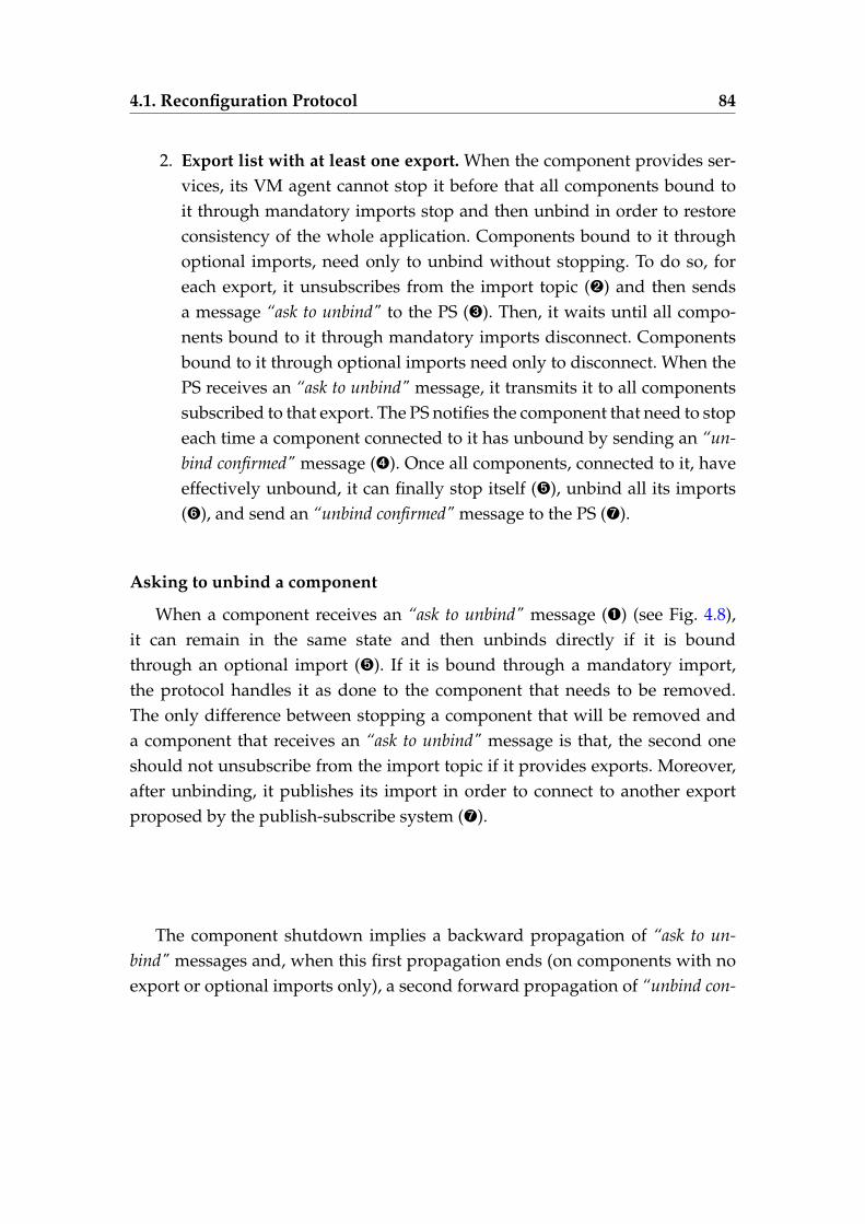
4.1. Reconfiguration Protocol 84
2. Export list with at least one export. When the component provides ser-vices, its VM agent cannot stop it before that all components bound toit through mandatory imports stop and then unbind in order to restoreconsistency of the whole application. Components bound to it throughoptional imports, need only to unbind without stopping. To do so, foreach export, it unsubscribes from the import topic (Ë) and then sendsa message “ask to unbind" to the PS (Ì). Then, it waits until all compo-nents bound to it through mandatory imports disconnect. Componentsbound to it through optional imports need only to disconnect. When thePS receives an “ask to unbind" message, it transmits it to all componentssubscribed to that export. The PS notifies the component that need to stopeach time a component connected to it has unbound by sending an “un-bind confirmed" message (Í). Once all components, connected to it, haveeffectively unbound, it can finally stop itself (Î), unbind all its imports(Ï), and send an “unbind confirmed" message to the PS (Ð).
Asking to unbind a component
When a component receives an “ask to unbind" message (Ê) (see Fig. 4.8),it can remain in the same state and then unbinds directly if it is boundthrough an optional import (Î). If it is bound through a mandatory import,the protocol handles it as done to the component that needs to be removed.The only difference between stopping a component that will be removed anda component that receives an “ask to unbind" message is that, the second oneshould not unsubscribe from the import topic if it provides exports. Moreover,after unbinding, it publishes its import in order to connect to another exportproposed by the publish-subscribe system (Ð).
The component shutdown implies a backward propagation of “ask to un-bind" messages and, when this first propagation ends (on components with noexport or optional imports only), a second forward propagation of “unbind con-
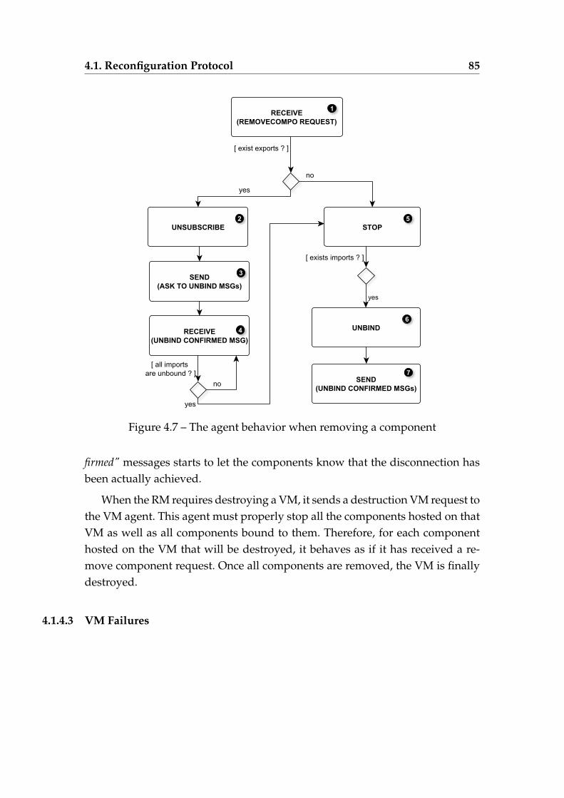
4.1. Reconfiguration Protocol 85
Figure 4.7 – The agent behavior when removing a component
firmed" messages starts to let the components know that the disconnection hasbeen actually achieved.
When the RM requires destroying a VM, it sends a destruction VM request tothe VM agent. This agent must properly stop all the components hosted on thatVM as well as all components bound to them. Therefore, for each componenthosted on the VM that will be destroyed, it behaves as if it has received a re-move component request. Once all components are removed, the VM is finallydestroyed.
4.1.4.3 VM Failures
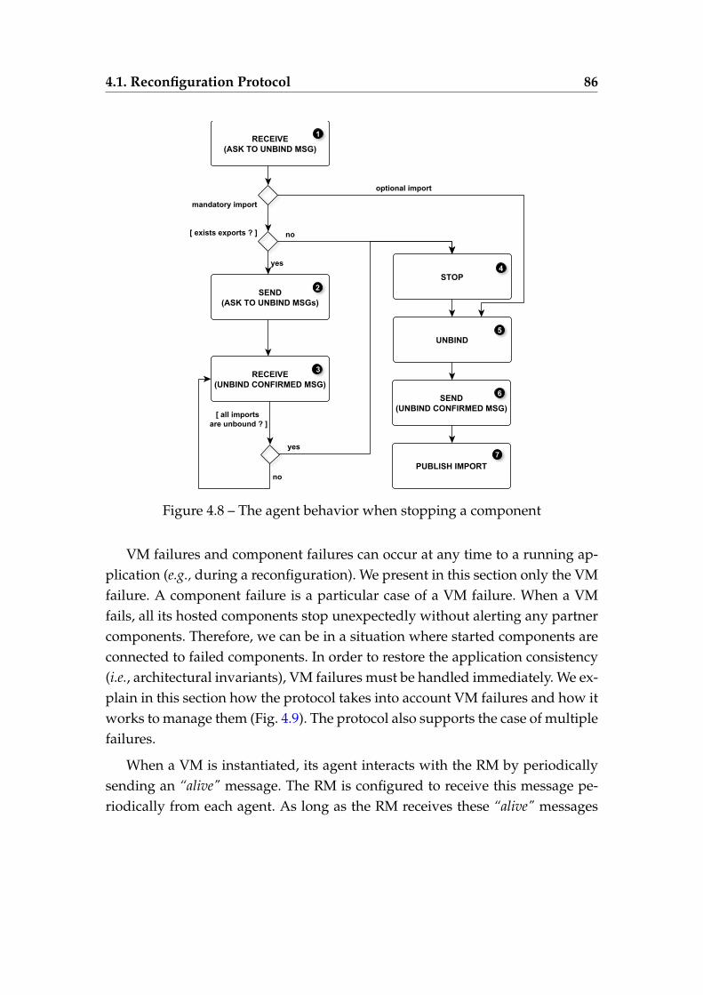
4.1. Reconfiguration Protocol 86
Figure 4.8 – The agent behavior when stopping a component
VM failures and component failures can occur at any time to a running ap-plication (e.g., during a reconfiguration). We present in this section only the VMfailure. A component failure is a particular case of a VM failure. When a VMfails, all its hosted components stop unexpectedly without alerting any partnercomponents. Therefore, we can be in a situation where started components areconnected to failed components. In order to restore the application consistency(i.e., architectural invariants), VM failures must be handled immediately. We ex-plain in this section how the protocol takes into account VM failures and how itworks to manage them (Fig. 4.9). The protocol also supports the case of multiplefailures.
When a VM is instantiated, its agent interacts with the RM by periodicallysending an “alive" message. The RM is configured to receive this message pe-riodically from each agent. As long as the RM receives these “alive" messages
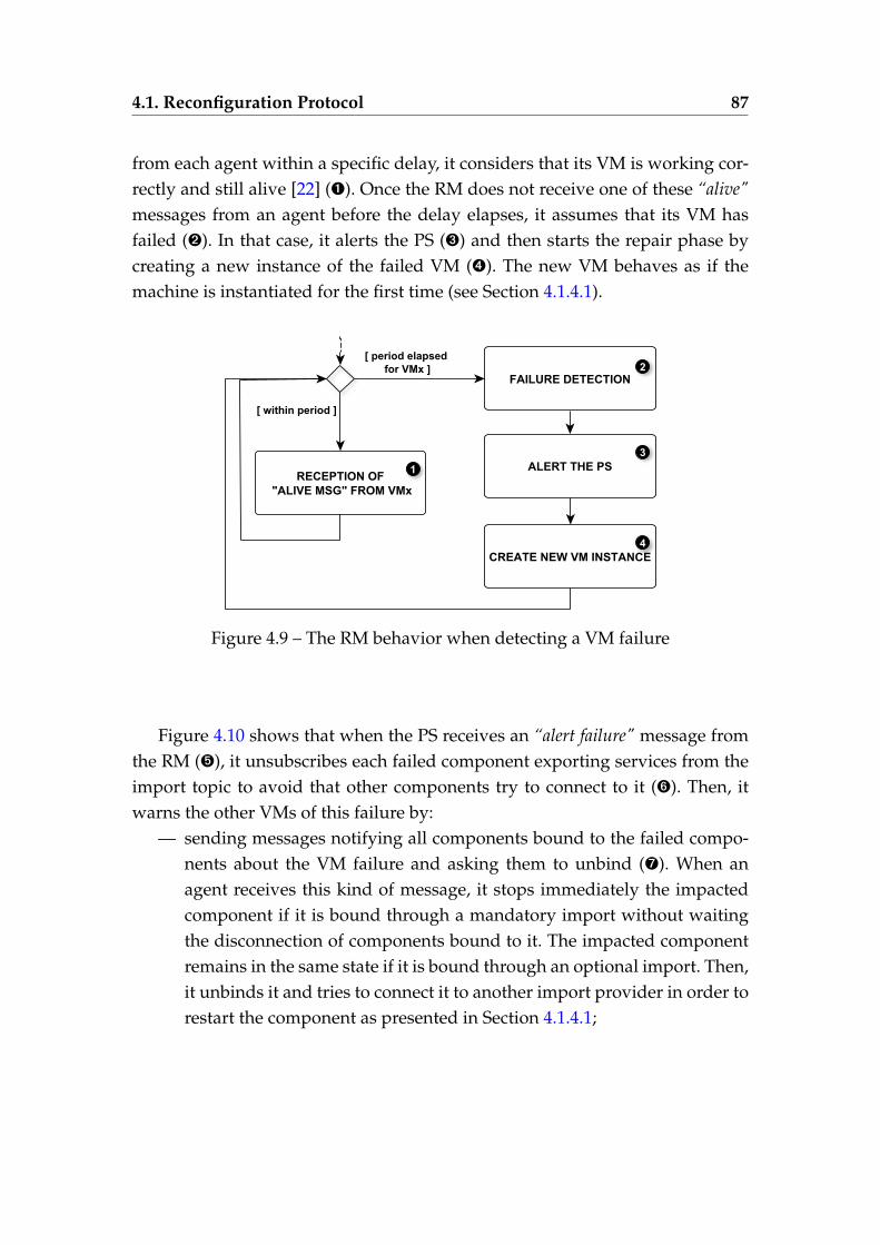
4.1. Reconfiguration Protocol 87
from each agent within a specific delay, it considers that its VM is working cor-rectly and still alive [22] (Ê). Once the RM does not receive one of these “alive"messages from an agent before the delay elapses, it assumes that its VM hasfailed (Ë). In that case, it alerts the PS (Ì) and then starts the repair phase bycreating a new instance of the failed VM (Í). The new VM behaves as if themachine is instantiated for the first time (see Section 4.1.4.1).
Figure 4.9 – The RM behavior when detecting a VM failure
Figure 4.10 shows that when the PS receives an “alert failure" message fromthe RM (Î), it unsubscribes each failed component exporting services from theimport topic to avoid that other components try to connect to it (Ï). Then, itwarns the other VMs of this failure by:
— sending messages notifying all components bound to the failed compo-nents about the VM failure and asking them to unbind (Ð). When anagent receives this kind of message, it stops immediately the impactedcomponent if it is bound through a mandatory import without waitingthe disconnection of components bound to it. The impacted componentremains in the same state if it is bound through an optional import. Then,it unbinds it and tries to connect it to another import provider in order torestart the component as presented in Section 4.1.4.1;
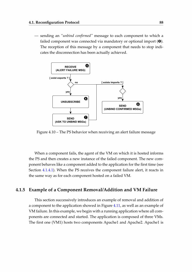
4.1. Reconfiguration Protocol 88
— sending an “unbind confirmed" message to each component to which afailed component was connected via mandatory or optional import (Ñ).The reception of this message by a component that needs to stop indi-cates the disconnection has been actually achieved.
Figure 4.10 – The PS behavior when receiving an alert failure message
When a component fails, the agent of the VM on which it is hosted informsthe PS and then creates a new instance of the failed component. The new com-ponent behaves like a component added to the application for the first time (seeSection 4.1.4.1). When the PS receives the component failure alert, it reacts inthe same way as for each component hosted on a failed VM.
4.1.5 Example of a Component Removal/Addition and VM Failure
This section successively introduces an example of removal and addition ofa component to the application showed in Figure 4.11, as well as an example ofVM failure. In this example, we begin with a running application where all com-ponents are connected and started. The application is composed of three VMs.The first one (VM1) hosts two components Apache1 and Apache2. Apache1 is
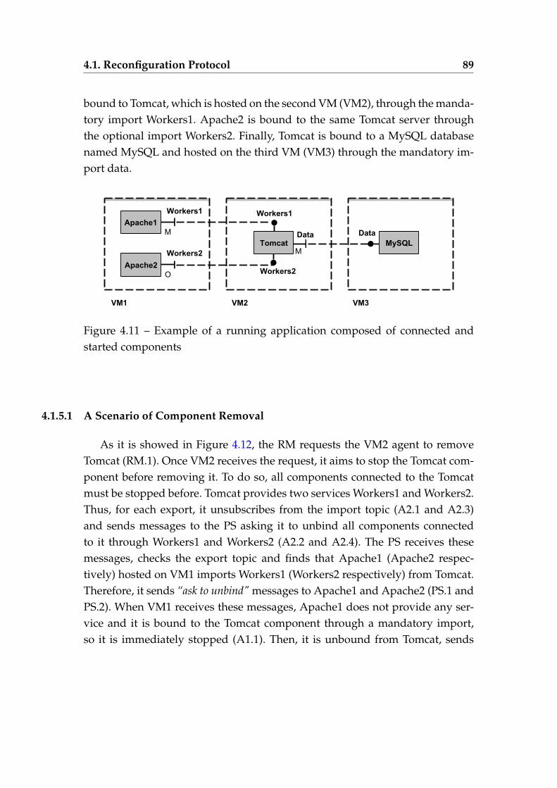
4.1. Reconfiguration Protocol 89
bound to Tomcat, which is hosted on the second VM (VM2), through the manda-tory import Workers1. Apache2 is bound to the same Tomcat server throughthe optional import Workers2. Finally, Tomcat is bound to a MySQL databasenamed MySQL and hosted on the third VM (VM3) through the mandatory im-port data.
Figure 4.11 – Example of a running application composed of connected andstarted components
4.1.5.1 A Scenario of Component Removal
As it is showed in Figure 4.12, the RM requests the VM2 agent to removeTomcat (RM.1). Once VM2 receives the request, it aims to stop the Tomcat com-ponent before removing it. To do so, all components connected to the Tomcatmust be stopped before. Tomcat provides two services Workers1 and Workers2.Thus, for each export, it unsubscribes from the import topic (A2.1 and A2.3)and sends messages to the PS asking it to unbind all components connectedto it through Workers1 and Workers2 (A2.2 and A2.4). The PS receives thesemessages, checks the export topic and finds that Apache1 (Apache2 respec-tively) hosted on VM1 imports Workers1 (Workers2 respectively) from Tomcat.Therefore, it sends “ask to unbind" messages to Apache1 and Apache2 (PS.1 andPS.2). When VM1 receives these messages, Apache1 does not provide any ser-vice and it is bound to the Tomcat component through a mandatory import,so it is immediately stopped (A1.1). Then, it is unbound from Tomcat, sends
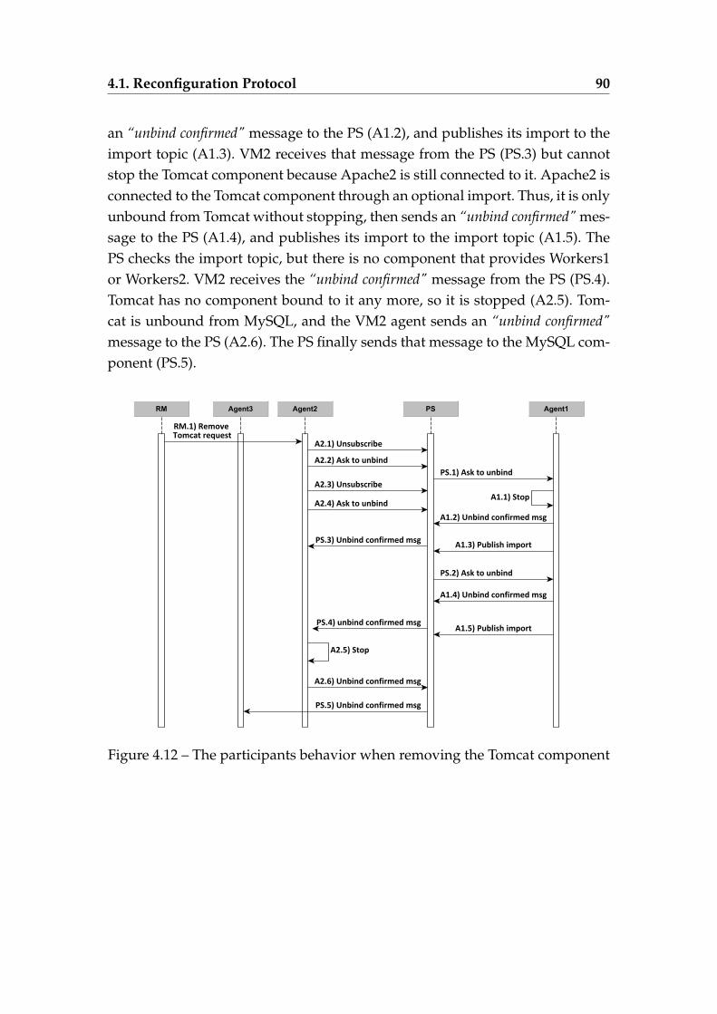
4.1. Reconfiguration Protocol 90
an “unbind confirmed" message to the PS (A1.2), and publishes its import to theimport topic (A1.3). VM2 receives that message from the PS (PS.3) but cannotstop the Tomcat component because Apache2 is still connected to it. Apache2 isconnected to the Tomcat component through an optional import. Thus, it is onlyunbound from Tomcat without stopping, then sends an “unbind confirmed" mes-sage to the PS (A1.4), and publishes its import to the import topic (A1.5). ThePS checks the import topic, but there is no component that provides Workers1or Workers2. VM2 receives the “unbind confirmed" message from the PS (PS.4).Tomcat has no component bound to it any more, so it is stopped (A2.5). Tom-cat is unbound from MySQL, and the VM2 agent sends an “unbind confirmed"message to the PS (A2.6). The PS finally sends that message to the MySQL com-ponent (PS.5).
Figure 4.12 – The participants behavior when removing the Tomcat component
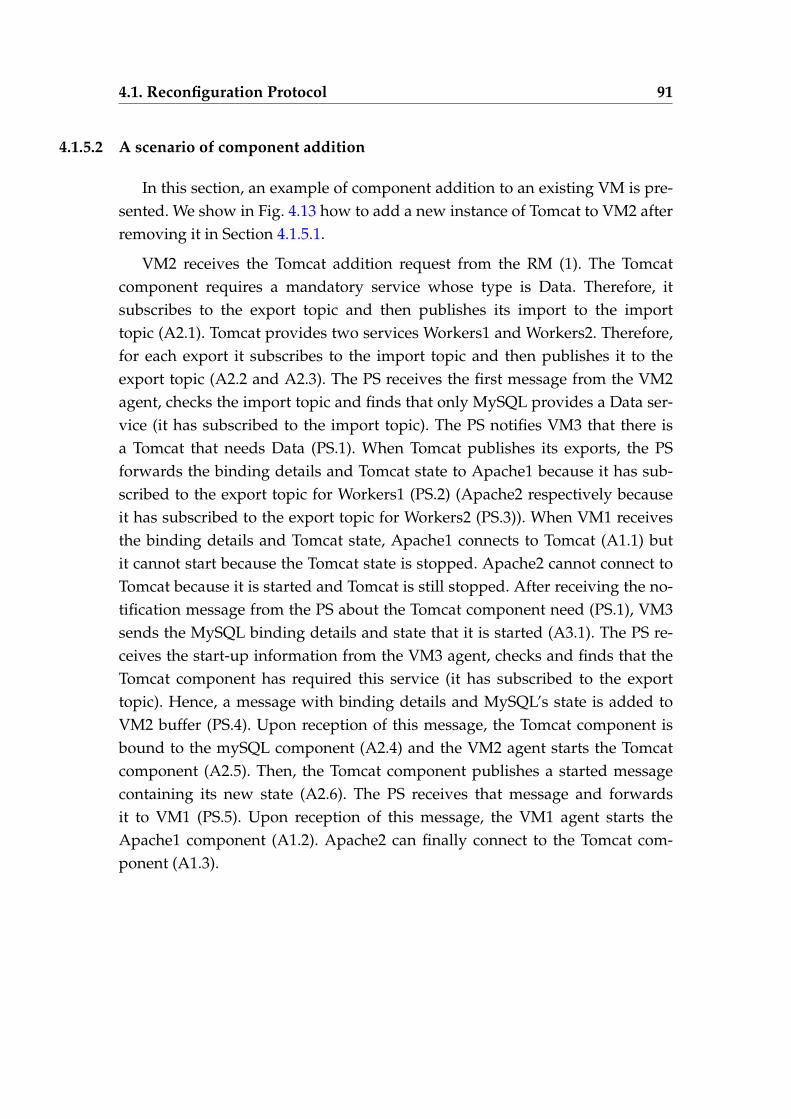
4.1. Reconfiguration Protocol 91
4.1.5.2 A scenario of component addition
In this section, an example of component addition to an existing VM is pre-sented. We show in Fig. 4.13 how to add a new instance of Tomcat to VM2 afterremoving it in Section 4.1.5.1.
VM2 receives the Tomcat addition request from the RM (1). The Tomcatcomponent requires a mandatory service whose type is Data. Therefore, itsubscribes to the export topic and then publishes its import to the importtopic (A2.1). Tomcat provides two services Workers1 and Workers2. Therefore,for each export it subscribes to the import topic and then publishes it to theexport topic (A2.2 and A2.3). The PS receives the first message from the VM2agent, checks the import topic and finds that only MySQL provides a Data ser-vice (it has subscribed to the import topic). The PS notifies VM3 that there isa Tomcat that needs Data (PS.1). When Tomcat publishes its exports, the PSforwards the binding details and Tomcat state to Apache1 because it has sub-scribed to the export topic for Workers1 (PS.2) (Apache2 respectively becauseit has subscribed to the export topic for Workers2 (PS.3)). When VM1 receivesthe binding details and Tomcat state, Apache1 connects to Tomcat (A1.1) butit cannot start because the Tomcat state is stopped. Apache2 cannot connect toTomcat because it is started and Tomcat is still stopped. After receiving the no-tification message from the PS about the Tomcat component need (PS.1), VM3sends the MySQL binding details and state that it is started (A3.1). The PS re-ceives the start-up information from the VM3 agent, checks and finds that theTomcat component has required this service (it has subscribed to the exporttopic). Hence, a message with binding details and MySQL’s state is added toVM2 buffer (PS.4). Upon reception of this message, the Tomcat component isbound to the mySQL component (A2.4) and the VM2 agent starts the Tomcatcomponent (A2.5). Then, the Tomcat component publishes a started messagecontaining its new state (A2.6). The PS receives that message and forwardsit to VM1 (PS.5). Upon reception of this message, the VM1 agent starts theApache1 component (A1.2). Apache2 can finally connect to the Tomcat com-ponent (A1.3).
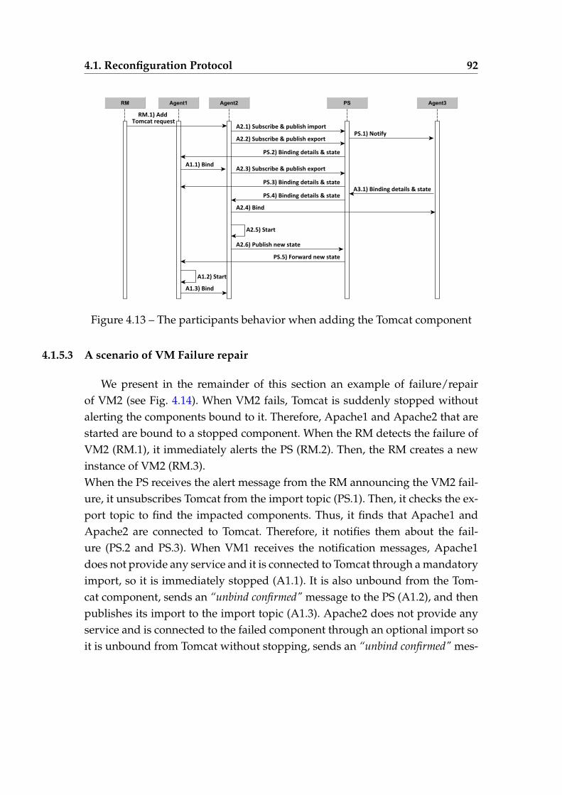
4.1. Reconfiguration Protocol 92
Figure 4.13 – The participants behavior when adding the Tomcat component
4.1.5.3 A scenario of VM Failure repair
We present in the remainder of this section an example of failure/repairof VM2 (see Fig. 4.14). When VM2 fails, Tomcat is suddenly stopped withoutalerting the components bound to it. Therefore, Apache1 and Apache2 that arestarted are bound to a stopped component. When the RM detects the failure ofVM2 (RM.1), it immediately alerts the PS (RM.2). Then, the RM creates a newinstance of VM2 (RM.3).When the PS receives the alert message from the RM announcing the VM2 fail-ure, it unsubscribes Tomcat from the import topic (PS.1). Then, it checks the ex-port topic to find the impacted components. Thus, it finds that Apache1 andApache2 are connected to Tomcat. Therefore, it notifies them about the fail-ure (PS.2 and PS.3). When VM1 receives the notification messages, Apache1does not provide any service and it is connected to Tomcat through a mandatoryimport, so it is immediately stopped (A1.1). It is also unbound from the Tom-cat component, sends an “unbind confirmed" message to the PS (A1.2), and thenpublishes its import to the import topic (A1.3). Apache2 does not provide anyservice and is connected to the failed component through an optional import soit is unbound from Tomcat without stopping, sends an “unbind confirmed" mes-
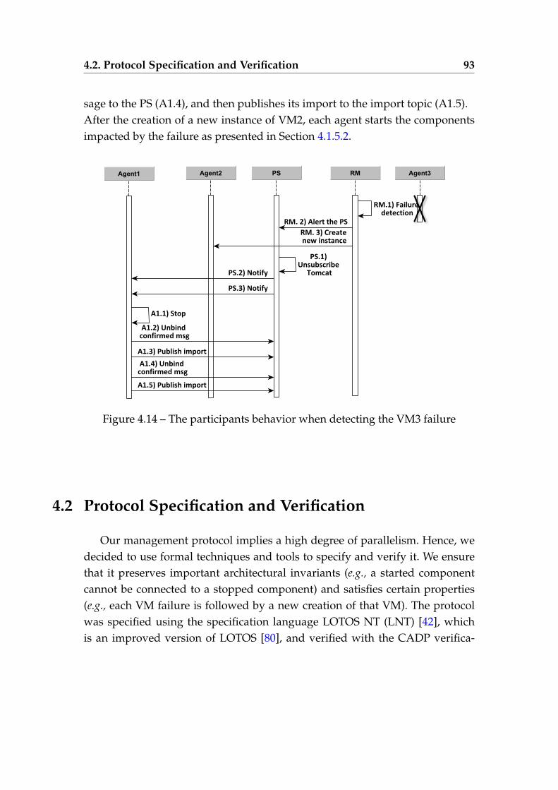
4.2. Protocol Specification and Verification 93
sage to the PS (A1.4), and then publishes its import to the import topic (A1.5).After the creation of a new instance of VM2, each agent starts the componentsimpacted by the failure as presented in Section 4.1.5.2.
Figure 4.14 – The participants behavior when detecting the VM3 failure
4.2 Protocol Specification and Verification
Our management protocol implies a high degree of parallelism. Hence, wedecided to use formal techniques and tools to specify and verify it. We ensurethat it preserves important architectural invariants (e.g., a started componentcannot be connected to a stopped component) and satisfies certain properties(e.g., each VM failure is followed by a new creation of that VM). The protocolwas specified using the specification language LOTOS NT (LNT) [42], whichis an improved version of LOTOS [80], and verified with the CADP verifica-
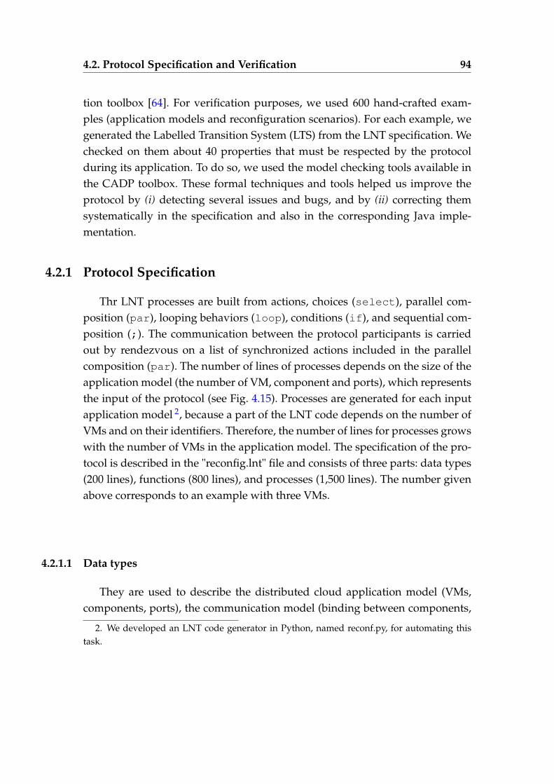
4.2. Protocol Specification and Verification 94
tion toolbox [64]. For verification purposes, we used 600 hand-crafted exam-ples (application models and reconfiguration scenarios). For each example, wegenerated the Labelled Transition System (LTS) from the LNT specification. Wechecked on them about 40 properties that must be respected by the protocolduring its application. To do so, we used the model checking tools available inthe CADP toolbox. These formal techniques and tools helped us improve theprotocol by (i) detecting several issues and bugs, and by (ii) correcting themsystematically in the specification and also in the corresponding Java imple-mentation.
4.2.1 Protocol Specification
Thr LNT processes are built from actions, choices (select), parallel com-position (par), looping behaviors (loop), conditions (if), and sequential com-position (;). The communication between the protocol participants is carriedout by rendezvous on a list of synchronized actions included in the parallelcomposition (par). The number of lines of processes depends on the size of theapplication model (the number of VM, component and ports), which representsthe input of the protocol (see Fig. 4.15). Processes are generated for each inputapplication model 2, because a part of the LNT code depends on the number ofVMs and on their identifiers. Therefore, the number of lines for processes growswith the number of VMs in the application model. The specification of the pro-tocol is described in the "reconfig.lnt" file and consists of three parts: data types(200 lines), functions (800 lines), and processes (1,500 lines). The number givenabove corresponds to an example with three VMs.
4.2.1.1 Data types
They are used to describe the distributed cloud application model (VMs,components, ports), the communication model (binding between components,
2. We developed an LNT code generator in Python, named reconf.py, for automating thistask.
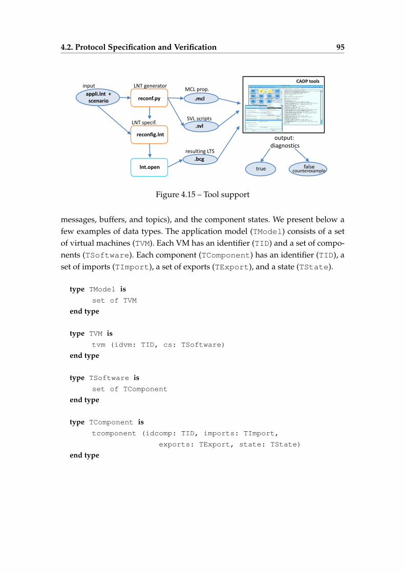
4.2. Protocol Specification and Verification 95
reconfig.lnt
appli.lnt + scenario
input
SVL scripts
resulting LTS
MCL prop.
CADP tools
LNT specif.
output: diagnostics
.bcg
true false counterexample
lnt.open
reconf.py
LNT generator
.svl
.mcl
Figure 4.15 – Tool support
messages, buffers, and topics), and the component states. We present below afew examples of data types. The application model (TModel) consists of a setof virtual machines (TVM). Each VM has an identifier (TID) and a set of compo-nents (TSoftware). Each component (TComponent) has an identifier (TID), aset of imports (TImport), a set of exports (TExport), and a state (TState).
type TModel isset of TVM
end type
type TVM istvm (idvm: TID, cs: TSoftware)
end type
type TSoftware isset of TComponent
end type
type TComponent istcomponent (idcomp: TID, imports: TImport,
exports: TExport, state: TState)
end type
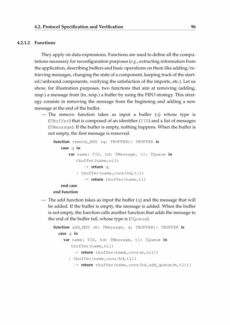
4.2. Protocol Specification and Verification 96
4.2.1.2 Functions
They apply on data expressions. Functions are used to define all the compu-tations necessary for reconfiguration purposes (e.g., extracting information fromthe application, describing buffers and basic operations on them like adding/re-trieving messages, changing the state of a component, keeping track of the start-ed/unbound components, verifying the satisfaction of the imports, etc.). Let usshow, for illustration purposes, two functions that aim at removing (adding,resp.) a message from (to, resp.) a buffer by using the FIFO strategy. This strat-egy consists in removing the message from the beginning and adding a newmessage at the end of the buffer.
— The remove function takes as input a buffer (q) whose type is(TBuffer) that is composed of an identifier (TID) and a list of messages(TMessage). If the buffer is empty, nothing happens. When the buffer isnot empty, the first message is removed.
function remove_MSG (q: TBUFFER): TBUFFER iscase q in
var name: TID, hd: TMessage, tl: TQueue intbuffer(name,nil)
-> return q
| tbuffer(name,cons(hd,tl))
-> return tbuffer(name,tl)
end caseend function
— The add function takes as input the buffer (q) and the message that willbe added. If the buffer is empty, the message is added. When the bufferis not empty, the function calls another function that adds the message tothe end of the buffer tail, whose type is (TQueue).
function add_MSG (m: TMessage, q: TBUFFER): TBUFFER iscase q in
var name: TID, hd: TMessage, tl: TQueue intbuffer(name,nil)
-> return tbuffer(name,cons(m,nil))
| tbuffer(name,cons(hd,tl))
-> return tbuffer(name,cons(hd,add_queue(m,tl)))
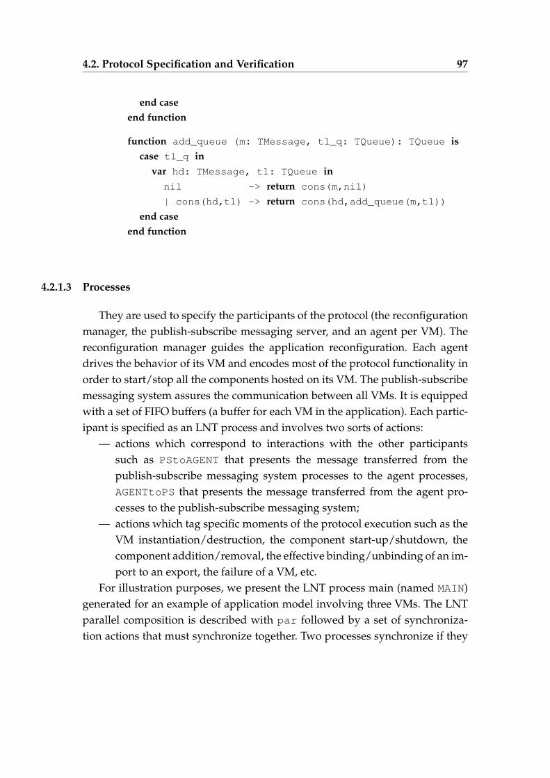
4.2. Protocol Specification and Verification 97
end caseend function
function add_queue (m: TMessage, tl_q: TQueue): TQueue iscase tl_q in
var hd: TMessage, tl: TQueue innil -> return cons(m,nil)
| cons(hd,tl) -> return cons(hd,add_queue(m,tl))
end caseend function
4.2.1.3 Processes
They are used to specify the participants of the protocol (the reconfigurationmanager, the publish-subscribe messaging server, and an agent per VM). Thereconfiguration manager guides the application reconfiguration. Each agentdrives the behavior of its VM and encodes most of the protocol functionality inorder to start/stop all the components hosted on its VM. The publish-subscribemessaging system assures the communication between all VMs. It is equippedwith a set of FIFO buffers (a buffer for each VM in the application). Each partic-ipant is specified as an LNT process and involves two sorts of actions:
— actions which correspond to interactions with the other participantssuch as PStoAGENT that presents the message transferred from thepublish-subscribe messaging system processes to the agent processes,AGENTtoPS that presents the message transferred from the agent pro-cesses to the publish-subscribe messaging system;
— actions which tag specific moments of the protocol execution such as theVM instantiation/destruction, the component start-up/shutdown, thecomponent addition/removal, the effective binding/unbinding of an im-port to an export, the failure of a VM, etc.
For illustration purposes, we present the LNT process main (named MAIN)generated for an example of application model involving three VMs. The LNTparallel composition is described with par followed by a set of synchroniza-tion actions that must synchronize together. Two processes synchronize if they
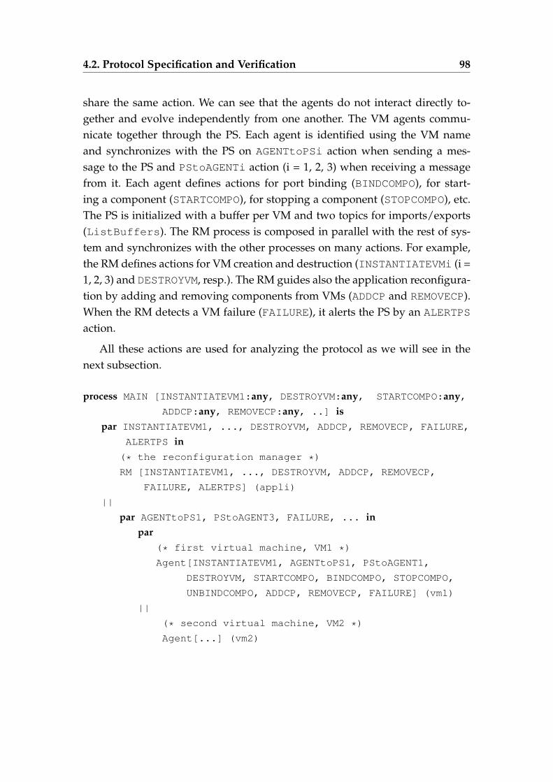
4.2. Protocol Specification and Verification 98
share the same action. We can see that the agents do not interact directly to-gether and evolve independently from one another. The VM agents commu-nicate together through the PS. Each agent is identified using the VM nameand synchronizes with the PS on AGENTtoPSi action when sending a mes-sage to the PS and PStoAGENTi action (i = 1, 2, 3) when receiving a messagefrom it. Each agent defines actions for port binding (BINDCOMPO), for start-ing a component (STARTCOMPO), for stopping a component (STOPCOMPO), etc.The PS is initialized with a buffer per VM and two topics for imports/exports(ListBuffers). The RM process is composed in parallel with the rest of sys-tem and synchronizes with the other processes on many actions. For example,the RM defines actions for VM creation and destruction (INSTANTIATEVMi (i =1, 2, 3) and DESTROYVM, resp.). The RM guides also the application reconfigura-tion by adding and removing components from VMs (ADDCP and REMOVECP).When the RM detects a VM failure (FAILURE), it alerts the PS by an ALERTPS
action.
All these actions are used for analyzing the protocol as we will see in thenext subsection.
process MAIN [INSTANTIATEVM1:any, DESTROYVM:any, STARTCOMPO:any,ADDCP:any, REMOVECP:any, ..] is
par INSTANTIATEVM1, ..., DESTROYVM, ADDCP, REMOVECP, FAILURE,
ALERTPS in(* the reconfiguration manager *)
RM [INSTANTIATEVM1, ..., DESTROYVM, ADDCP, REMOVECP,
FAILURE, ALERTPS] (appli)
||
par AGENTtoPS1, PStoAGENT3, FAILURE, ... inpar
(* first virtual machine, VM1 *)
Agent[INSTANTIATEVM1, AGENTtoPS1, PStoAGENT1,
DESTROYVM, STARTCOMPO, BINDCOMPO, STOPCOMPO,
UNBINDCOMPO, ADDCP, REMOVECP, FAILURE] (vm1)
||
(* second virtual machine, VM2 *)
Agent[...] (vm2)
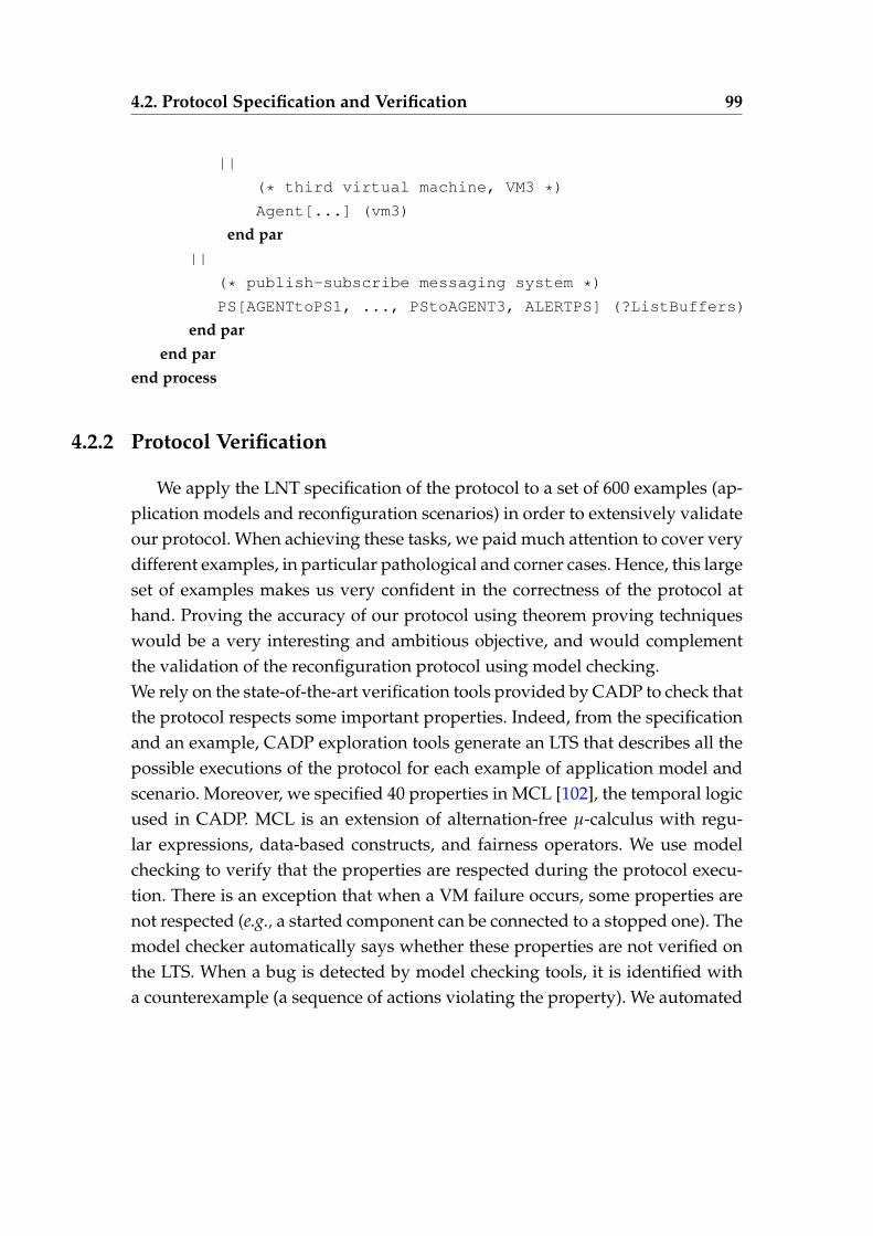
4.2. Protocol Specification and Verification 99
||
(* third virtual machine, VM3 *)
Agent[...] (vm3)
end par||
(* publish-subscribe messaging system *)
PS[AGENTtoPS1, ..., PStoAGENT3, ALERTPS] (?ListBuffers)
end parend par
end process
4.2.2 Protocol Verification
We apply the LNT specification of the protocol to a set of 600 examples (ap-plication models and reconfiguration scenarios) in order to extensively validateour protocol. When achieving these tasks, we paid much attention to cover verydifferent examples, in particular pathological and corner cases. Hence, this largeset of examples makes us very confident in the correctness of the protocol athand. Proving the accuracy of our protocol using theorem proving techniqueswould be a very interesting and ambitious objective, and would complementthe validation of the reconfiguration protocol using model checking.We rely on the state-of-the-art verification tools provided by CADP to check thatthe protocol respects some important properties. Indeed, from the specificationand an example, CADP exploration tools generate an LTS that describes all thepossible executions of the protocol for each example of application model andscenario. Moreover, we specified 40 properties in MCL [102], the temporal logicused in CADP. MCL is an extension of alternation-free µ-calculus with regu-lar expressions, data-based constructs, and fairness operators. We use modelchecking to verify that the properties are respected during the protocol execu-tion. There is an exception that when a VM failure occurs, some properties arenot respected (e.g., a started component can be connected to a stopped one). Themodel checker automatically says whether these properties are not verified onthe LTS. When a bug is detected by model checking tools, it is identified witha counterexample (a sequence of actions violating the property). We automated
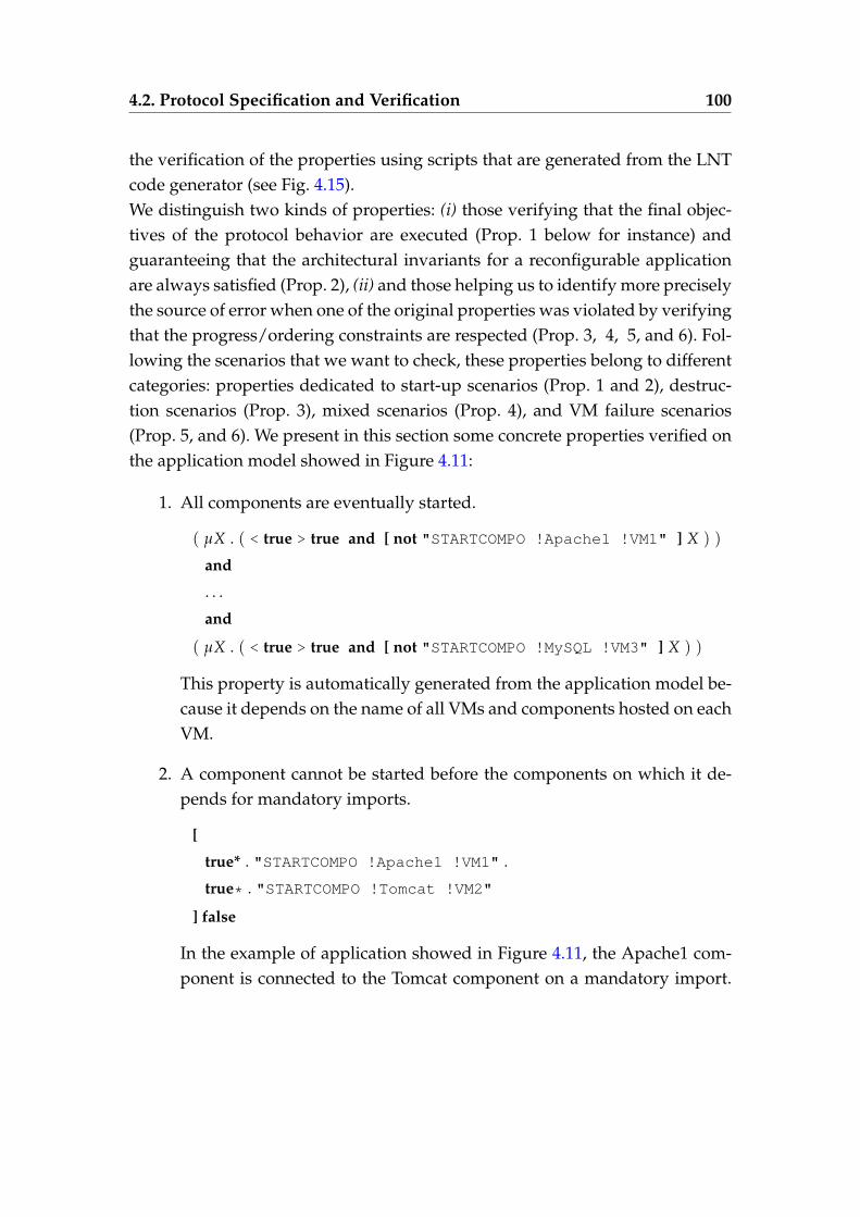
4.2. Protocol Specification and Verification 100
the verification of the properties using scripts that are generated from the LNTcode generator (see Fig. 4.15).We distinguish two kinds of properties: (i) those verifying that the final objec-tives of the protocol behavior are executed (Prop. 1 below for instance) andguaranteeing that the architectural invariants for a reconfigurable applicationare always satisfied (Prop. 2), (ii) and those helping us to identify more preciselythe source of error when one of the original properties was violated by verifyingthat the progress/ordering constraints are respected (Prop. 3, 4, 5, and 6). Fol-lowing the scenarios that we want to check, these properties belong to differentcategories: properties dedicated to start-up scenarios (Prop. 1 and 2), destruc-tion scenarios (Prop. 3), mixed scenarios (Prop. 4), and VM failure scenarios(Prop. 5, and 6). We present in this section some concrete properties verified onthe application model showed in Figure 4.11:
1. All components are eventually started.
( µX . ( < true > true and [ not "STARTCOMPO !Apache1 !VM1" ] X ) )
and
. . .
and
( µX . ( < true > true and [ not "STARTCOMPO !MySQL !VM3" ] X ) )
This property is automatically generated from the application model be-cause it depends on the name of all VMs and components hosted on eachVM.
2. A component cannot be started before the components on which it de-pends for mandatory imports.
[
true* . "STARTCOMPO !Apache1 !VM1" .
true* . "STARTCOMPO !Tomcat !VM2"
] false
In the example of application showed in Figure 4.11, the Apache1 com-ponent is connected to the Tomcat component on a mandatory import.
4.2. Protocol Specification and Verification 101
Therefore, we must never find a sequence where Apache1 is started be-fore Tomcat. This property is automatically generated from the applica-tion model because it depends on the component and VM names in theapplication model.
3. All components hosted on a VM eventually stop after that VM receives adestruction request from the DM.
[ true* . { DESTROYVM ?vm:String } ]
inev ( { STOPCOMPO ?cid:String !vm } )
This property does not depend on the application. It can be verified forany application without knowing the name of VMs and components. Pa-rameters can be related in MCL by using variables in action parameters(e.g., vm for the virtual machine identifier and cid for the componentidentifier). This property shows the data-based features that are avail-able in MCL.
4. There is no sequence where an import (mandatory or optional) is boundtwice without an unbind in between.
[ true* .
"BINDCOMPO !Apache1 !Workers1" .
( not "UNBINDCOMPO !Apache1 !VM1" )* .
"BINDCOMPO !Apache1 !Workers1"
] false
When a component is connected to another component through an im-port (mandatory or optional), it cannot be bound again except if it is un-bound before.
5. There is no sequence with two VM instantiations without a failure or adestroy in between.
[ true* .
"INSTANTIATEVM1" .
( not "FAILURE !VM1 or DESTROY !VM1" )* .
4.3. Experiments 102
"INSTANTIATEVM1"
] false
When a VM is instantiated, it cannot be instantiated again except if thisVM is destroyed or failed.
6. A failure action in the VM is eventually followed by an alert of this failure
[ true* . { FAILURE ?vm:String } ] inev ( { ALERTPS !vm } )
This property does not depend on the application. The variable vm (thevirtual machine identifier) used as first parameter of FAILURE must bethe first parameter in ALERTPS. This property is verified for all applica-tions and all VM names.
This property and property 3 use the macro inev (M), which indicatesthat a transition labeled with M eventually occurs. This macro is definedas follows:
macro inev (M) = mu x .( < true > true and [ not M ] X )
end macro
4.3 Experiments
We conducted our experiments on more than 600 hand-crafted exampleson a Pentium 4 (2.5GHz, 8GB RAM) running Linux. Each example consists ofan application model and a specific scenario (a sequence of instantiate/destroyVM operations and add/remove components to/from VMs). From this input,the CADP exploration tools generate the corresponding LTS by enumeratingall the possible executions of the system. Finally, the CADP model checker iscalled, providing as results a set of diagnostics (true or false). The model checkerreturns true if a property is verified. When a property is not satisfied, it returnsfalse as well as a counterexample. We present in this section experiments thatsummarize some of the numbers obtained when varying the number of VMs,the number of reconfiguration operations, and the number of failures.
4.3. Experiments 103
We present in Figure 4.16 (left) the size of the LTS (transitions) as well asthe time to execute the whole process (LTS generation and properties checking)when we modify the application model. We only instantiate VMs without de-stroying VMs and thus, the number of reconfiguration operations is the same asthe VM number. Increasing the VMs number leads to an increase of the numberof components and ports. Then, the more VMs and ports, the more parallelismin the system and, therefore, the more messages exchanged among VMs. Fig-ure 4.16 (left) shows how the LTS size grows exponentially when we slightlyincrease the number of VMs in the application. The computation time scalesfrom a few minutes for applications with 1 VM and few ports to a few hours foran application with 4 or more VMs.
Figure 4.16 (right) summarizes the results obtained for the same applicationused to get results showed in Figure 4.16 (left) but with a destruction and re-instantiation operations at the end of the scenario. The LTSs size and analysistime increase in a remarkable way even when just adding one destruction op-eration to the same application. This operation triggers a double propagation,hence more exchanged messages between the PS and the agents.
Table 4.1 shows the size of the LTS (states and transitions) before and afterminimization (wrt. a strong bisimulation relation) as well as the time to executethe whole process in the last column of the tables (LTS generation and mini-mization on the one hand, and properties checking on the other). These resultsare obtained for the application described in Figure 4.11, with an increasingnumber of failures (F). The more VMs fail, the more the LTS size and analysistime increase.
Fortunately, our goal here was not to analyze huge systems (with poten-tially many VMs) during the verification of the protocol but to find bugs inthe protocol. Indeed, most issues were found on small applications describingpathological reconfiguration cases.
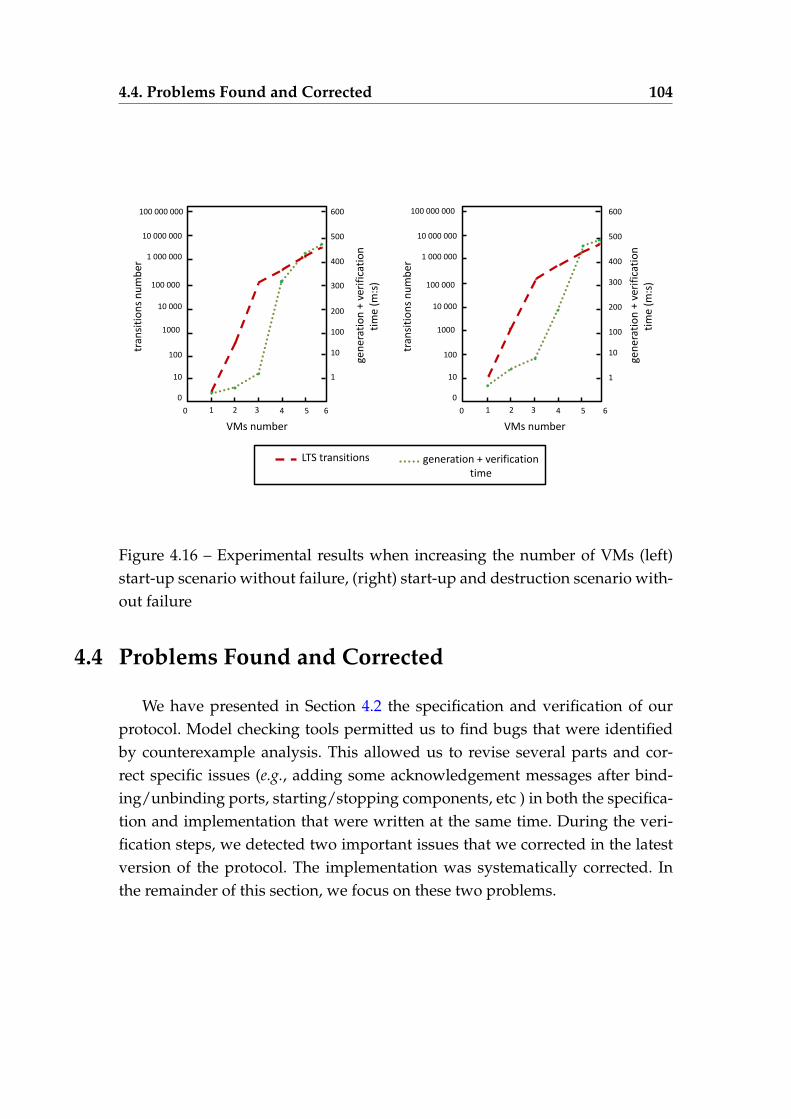
4.4. Problems Found and Corrected 104
tran
siti
on
s n
um
ber
10
100
1000
0
10 000
100 000
1 000 000
10 000 000
1
10
100
500
200
300
400
gen
erat
ion
+ v
erif
icat
ion
ti
me
(m:s
)
LTS transitions generation + verification time
3 4 5 6 0
10
100
1000
0
1
10
100
500
10 000
100 000
1 000 000
10 000 000
2 1
200
300
400
gen
erat
ion
+ v
erif
icat
ion
ti
me
(m:s
)
600 600 100 000 000 100 000 000
3 4 5 6 0 2 1 tr
ansi
tio
ns
nu
mb
er
VMs number VMs number
Figure 4.16 – Experimental results when increasing the number of VMs (left)start-up scenario without failure, (right) start-up and destruction scenario with-out failure
4.4 Problems Found and Corrected
We have presented in Section 4.2 the specification and verification of ourprotocol. Model checking tools permitted us to find bugs that were identifiedby counterexample analysis. This allowed us to revise several parts and cor-rect specific issues (e.g., adding some acknowledgement messages after bind-ing/unbinding ports, starting/stopping components, etc ) in both the specifica-tion and implementation that were written at the same time. During the veri-fication steps, we detected two important issues that we corrected in the latestversion of the protocol. The implementation was systematically corrected. Inthe remainder of this section, we focus on these two problems.
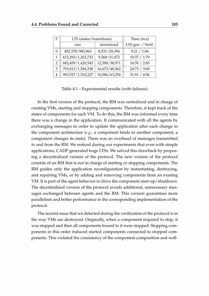
4.4. Problems Found and Corrected 105
F LTS (states/transitions) Time (m:s)raw minimized LTS gen. / Verif.
0 452,378/983,963 8,531/29,394 9:21 / 1:841 612,293/1,262,732 9,568/31,472 10:37 / 1:792 682,459/1,420,543 12,390/38,971 16:59 / 2:833 793,813/1,584,238 16,673/48,562 24:73 / 3:694 993,527/1,763,227 19,586/63,254 31:91 / 4:56
Table 4.1 – Experimental results (with failures)
In the first version of the protocol, the RM was centralized and in charge ofcreating VMs, starting and stopping components. Therefore, it kept track of thestates of components for each VM. To do this, the RM was informed every timethere was a change in the application. It communicated with all the agents byexchanging messages in order to update the application after each change inthe component architecture (e.g., a component binds to another component, acomponent changes its state). There was an overhead of messages transmittedto and from the RM. We noticed during our experiments that even with simpleapplications, CADP generated huge LTSs. We solved this drawback by propos-ing a decentralized version of the protocol. The new version of the protocolconsists of an RM that is not in charge of starting or stopping components. TheRM guides only the application reconfiguration by instantiating, destroying,and repairing VMs, or by adding and removing components from an existingVM. It is part of the agent behavior to drive the component start-up/shutdown.The decentralized version of the protocol avoids additional, unnecessary mes-sages exchanged between agents and the RM. This version guarantees moreparallelism and better performance in the corresponding implementation of theprotocol.
The second issue that we detected during the verification of the protocol is inthe way VMs are destroyed. Originally, when a component required to stop, itwas stopped and then all components bound to it were stopped. Stopping com-ponents in this order induced started components connected to stopped com-ponents. This violated the consistency of the component composition and well-
4.5. Protocol Implementation 106
formedness architectural invariants. This bug was detected thanks to a prop-erty stating that “ a component cannot be started and connected through an import(mandatory or optional) to a stopped component ". Thus, we corrected this bug byproposing another way to stop components. When a component needs to stop,it requests to all components bound to it to unbind, and once it is done, it canimmediately stop. This implies first a backward propagation along componentsbound on mandatory imports. Once this first propagation stops (a componentdoes not provide service or is connected only through optional imports), westart a forward propagation during which components are actually stopped andindicate to their partners that they have just stopped and unbound. This dou-ble propagation, as presented in Section 4.1.4.2, is necessary for preserving thecomponent architecture consistency and for avoiding that started componentscan keep on using stopped components.
4.5 Protocol Implementation
The protocol was implemented by another partner of the OpenCloudwareproject in RoboConf [114]. Roboconf is a system for configuring, installing, andmanaging complex legacy application stacks deployed on the cloud which dy-namically evolve in time 3. We present in this section some implementation de-tails concerning the protocol. The core of the system of our implementation isroughly 6K lines of Java code. It is based on an IaaS abstraction that allows toinstantiate VMs on different IaaS layers (such as Amazon EC2 and MicrosoftAzure) and on RabbitMQ 4, which is an implementation of the AMQP stan-dard 5. It is a message server, implementing the publish-subscribe messagingsystem. It is mainly used for the communication between VMs and RM. AnAMQP communication system was chosen in order to have a reliable and asyn-chronous communication system.
When the user requests the deployment of a new software instance, the RMfirst contacts the IaaS API to check about the VM instance defined in the soft-
3. http://roboconf.net/fr/index.html4. http://www.rabbitmq.com/5. http://www.amqp.org
4.5. Protocol Implementation 107
ware instance model. If the user asks to deploy the software application on analready existing VM instance, the RM immediately sends the model to the VM.Otherwise, the RM checks if the software type of the software instance has a VMtype defined. If so, the RM asks the IaaS to instantiate one VM of this kind. Oth-erwise, the RM asks the IaaS to instantiate a VM from the default VM template.When the RM asks the IaaS to instantiate a VM, it creates a message buffer onthe message server (implementing the publish-subscribe messaging server) forthat VM.
When the RM sends the software instance model to the VM instance, it seri-alizes the software instance object and sends it to the message buffer of the VMalong with the configuration files (Puppet recipes for example). This part canbe done even when the VM is not running thanks to the messages stored in itsmessage buffer. When the VM boots, the agent starts, connects to the messagebuffer and gets the message.
The agent on the VM gets the software instance model and the configurationfiles associated with it. It checks what “connector” it has to use to perform theoperations for the software instance. A connector is a Java class that implementsthe four operations: setup, update, start, and stop. A connector is independentfrom any software it will install, it only does basic operations. The operations re-lated to the software are located in the configuration files. Each connector, whencalling a basic operation, transmits the configuration of the model (such as vari-ables and imported variables) to the packaging and configuration system. Thismechanism enables the user to separate actual operations on VM from bindingdetails. Multiple connectors enable users to keep the original way of installingand configuring the software. In addition, it also enables to cover almost anykind of software: from software available in Linux repositories to legacy soft-ware. A Puppet 6 connector was implemented in order to install and updatesoftware on VMs. Puppet is one of the most known configuration systems. Itprovides a language and a program. The language enables to describe the stateof a system by describing its packages, files, and services.
When the installation is completed (software instances are installed onVMs), each agent publishes its configuration (according to the exports) and sub-
6. http://docs.puppetlabs.com/
4.6. Conclusion 108
scribes to other remote configurations (according to the imports) by using theRabbitMQ API.
4.6 Conclusion
We have successively presented in this chapter the design, specification,and verification of a novel reconfiguration protocol involving components dis-tributed over several VMs. This protocol enables one to instantiate new VM-s/destroy existing VMs and add a new component/remove an existent one.Upon reception of one of these reconfiguration operations, each VM agent con-nects/disconnects and starts/stops components in a particular order in orderto preserve the application consistency (i.e., architectural invariants), which isquite complicated due to the high parallelism degree of this protocol. The pro-tocol also supports the VMs failures. It detects failures and repairs them by cre-ating new instances of the failed VMs. We specified and verified our protocolusing the LNT specification language and the CADP toolbox, which is consid-ered as very convenient for modeling and analyzing such protocols. We usedmodel checking techniques to verify 40 properties of interest on a large num-ber of application models and reconfiguration scenarios. The experience wassuccessful because we detected several issues that were corrected in the corre-sponding Java implementation, which is established by another partner of theOpenCloudware project. In particular, we deeply revised the part of the proto-col dedicated to the VM destruction and component shutdown.
5Asynchronous Coordination of
Stateful Autonomic Managers in theCloud
" The value of achievement lies in the achieving. "
Albert Einstein
Contents
5.1 Formal Models . . . . . . . . . . . . . . . . . . . . . . . . . . . . 112
5.1.1 Autonomic Manager Model . . . . . . . . . . . . . . . . 113
5.1.2 Coordination Requirements Specification . . . . . . . . 113
5.2 Asynchronous Synthesis Techniques . . . . . . . . . . . . . . . 114
5.2.1 Process Algebra Encoding . . . . . . . . . . . . . . . . . 115
110
5.2.2 Compilation and Verification . . . . . . . . . . . . . . . 120
5.3 Java Code Generation and Deployment . . . . . . . . . . . . . . 122
5.3.1 Java Code Generation Techniques . . . . . . . . . . . . 122
5.3.2 Deployment . . . . . . . . . . . . . . . . . . . . . . . . . 122
5.4 A Multi-tier Application Supervised by Autonomic Managers . 123
5.4.1 Multi-Tier Application . . . . . . . . . . . . . . . . . . . 123
5.4.2 The Managers Role . . . . . . . . . . . . . . . . . . . . . 124
5.4.3 The Managers Models . . . . . . . . . . . . . . . . . . . 125
5.4.4 Coordinated Problems . . . . . . . . . . . . . . . . . . . 126
5.4.5 Managers Coordination . . . . . . . . . . . . . . . . . . 127
5.4.6 Encoding into LNT . . . . . . . . . . . . . . . . . . . . . 128
5.4.7 Compilation and Verification . . . . . . . . . . . . . . . 131
5.4.8 Deploying and Running the Generated Controller . . . 133
5.5 Conclusion . . . . . . . . . . . . . . . . . . . . . . . . . . . . . . 135
111
THis thesis proposes new techniques that aim at automatically monitoringand updating complex distributed applications. Managing these applica-
tions is a challenging problem because the manual administration is no longerrealistic for complex systems. Thus, autonomic computing is a promising solu-tion for automating the administration functions, which focus particularly onreplicating virtual machines, destroying or adding them, and handling VM fail-ures in the cloud. These operations are executed by different autonomic man-agers considered as control loops. Each manager observes the application ex-ecution, ensures a continuous monitoring, and immediately reacts to changesby automatically executing reconfiguration tasks. Several managers can be de-ployed to manage the same application and must make consistent decisions.Nonetheless, using them without coordination may lead the system into in-consistencies and error-prone situations (e.g., removing a server that will beneeded). As a consequence, the use of multiple managers (e.g., self-repair andself-sizing managers) implemented in the same system requires taking glob-ally consistent decisions. Hence, a manager should be aware of decisions of allmanagers before reacting. We present in this chapter our synthesis techniquesfor generating a controller, which aims at coordinating several managers. Thegenerated controller prevents every manager from violating global objectives ofall the managers. Our controller synthesis techniques ensure an asynchronousinteraction of all the managers with the generated controller, meaning that allthe messages transmitted from/to the managers (controller, resp.) are stored/-consumed into/from FIFO buffers.
More precisely, an autonomic manager is described using a formal model,namely a Labelled Transition System (LTS). We defined a set of reaction rulesand regular expressions to specify the coordination requirements and interac-tion constraints. As a consequence, each manager is not only able to manageits internal behaviour but also its relationship with other autonomic managers,which is achieved by the specification of the coordination requirements. Look-ing at Figure 5.1, one can observe that our controller synthesis techniques relyon an encoding of our inputs (LTS models and coordination requirements) intothe LNT process algebra. We particularly used the CADP compilers and mini-mization tools (e.g., strong equivalence) to generate a reduced LTS from the LNTspecification. The generated LTS corresponds to all possible executions of the
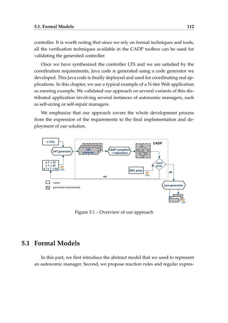
5.1. Formal Models 112
controller. It is worth noting that since we rely on formal techniques and tools,all the verification techniques available in the CADP toolbox can be used forvalidating the generated controller.
Once we have synthesized the controller LTS and we are satisfied by thecoordination requirements, Java code is generated using a code generator wedeveloped. This Java code is finally deployed and used for coordinating real ap-plications. In this chapter, we use a typical example of a N-tier Web applicationas running example. We validated our approach on several variants of this dis-tributed application involving several instances of autonomic managers, suchas self-sizing or self-repair managers.
We emphasize that our approach covers the whole development processfrom the expression of the requirements to the final implementation and de-ployment of our solution.
Figure 5.1 – Overview of our approach
5.1 Formal Models
In this part, we first introduce the abstract model that we used to representan autonomic manager. Second, we propose reaction rules and regular expres-
5.1. Formal Models 113
sions for specifying how the involved managers are supposed to interact to-gether through the controller that we want to generate. The managers modelsand the coordination expressions are used as inputs to our synthesis technique(see Section 5.2).
5.1.1 Autonomic Manager Model
Each autonomic manager is modelled as a Labelled Transition System (LTS),which consists of a set of states and transitions that occur between those states.Formally, an LTS is defined as follows:
Definition 4. A Labelled Transition System is a tuple defined as LTS = (Q, A, T, q0)
where Q is a finite set of states, A = A! ∪ A? is an alphabet partitioned into a set ofsend and received messages, T ⊆ Q× A× Q is a transition relation, and q0 ∈ Q isthe initial state.
We refer to a send message m ∈ A!, which must be required and consumedby another manager or by the controller, as m!. We refer to a received messagem ∈ A?, which is consumed by the actual manager, as m?. A transition that oc-
curs between two states is represented as q l−→ q′ ∈ T where q, q′ ∈ Q and l ∈ A.We assume that managers are deterministic, which can be easily obtained usingstandard determinization algorithms [79].Given a set of manager LTSs, where every manager is defined as (Qi, Ai, Ti, q0
i ),we assume that each message should have a unique sender and a unique re-ceiver: ∀i, j ∈ 1..n, i 6= j, A!
i ∩ A!j = ∅ and A?
i ∩ A?j = ∅. Furthermore, each
message is exchanged between two different managers: A!i ∩ A?
i = ∅ for all i.The uniqueness of messages can be achieved via renaming.
5.1.2 Coordination Requirements Specification
The backbone of our approach is the coordination of multiple managers,handling the same system, using a generated controller. To do this, we use reac-tion rules and regular expressions with their basic operators, such as sequence,choice, and iteration, to describe the behaviour one expects from the controller.
5.2. Asynchronous Synthesis Techniques 114
The generated controller aims at orchestrating the execution of the managers.We define a reaction rule as a set of receptions followed by a set of emissions.Basically, it expresses that when the controller receives a set of messages frommanagers within a certain period of time (left hand part), it must send all themessages specified in the second set (right hand part) once the period is expired.We note that the real period will be chosen during the deployment phase, andboth sets of messages can be received and emitted in any order.
Definition 5. Given a set of managers {M1, . . . , Mn} with Mi = (Qi, Ai, Ti, q0i ), a
reaction rule R is defined as a1, ..., am→ b1, ..., bp where aj presents a message receivedfrom a manager Mi (aj ∈ A?
i ) and bk presents a message emitted to a manager Ml
(bk ∈ A!l) for 1 6 j 6 m and 1 6 k 6 p.
The specification of the behaviour one expects from the controller is ex-pressed using a coordination expression C.
Definition 6. A coordination expression C is a regular expression over reaction rulesR:
C ::= R | C1.C2 | C1 + C2 | C∗where C1.C2 represents a coordination expression C1 followed by C2, C1 +C2 representsthe choice between C1 and C2, and C∗ presents a repetition of C zero or several times.
It is worth noting that all participants, namely the autonomic managersand the controller to be generated, communicate asynchronously using mes-sage passing via FIFO buffers. Each participant is equipped with one inputbuffer. Therefore, it consumes messages from its buffer and sends messages thatare putted at the input buffer of the message’s recipients. Once generated andadded to the system, all managers communicate through the controller, whichmeans that the controller acts as a centralized orchestrator for the whole system.
5.2 Asynchronous Synthesis Techniques
5.2. Asynchronous Synthesis Techniques 115
In this section, we present new asynchronous controller synthesis tech-niques, which rely on an encoding of our models (aut format 1) and coordi-nation requirements into the LNT specification language. From this LNT spec-ification, we can generate the corresponding LTS model of the controller usingCADP compilers, hiding, and reduction techniques. We also use CADP verifi-cation tools to validate the generated controller. All the steps presented in thissection are fully automated using a tool that we developed in Python 2. Thistool generates the LNT code as well as SVL scripts that are used for invokingCADP exploration and reduction tools, which finally results in the generationof the controller LTS.
5.2.1 Process Algebra Encoding
We present successively in this section the encoding into LNT of the differentparts of our system, i.e., autonomic managers, coordination requirements, andarchitecture.
5.2.1.1 Encoding of An Autonomic Manager
An LNT process is generated for each state in the manager LTS. Each processis named using the state identifier of the corresponding state. The alphabet ofthe process consists of the set of send and receive messages appearing on theLTS transitions. The behavior of the process encodes all the transitions of theLTS going out from the corresponding state and eventually calls the processesencoding the target states of those transitions. Actually, if there is no such transi-tion, the body of the process is the null statement. If there is a single transition,the body of the process corresponds to the message labelling this transition, fol-lowed by a call to the process encoding the target state of the transition. Finally,if there is more than one transition, we use the select operator. Let us assume
that two transitions ql−→ q’, q
l′−→ q” ∈ T have the same source state q. Thebehavior of the process encoding q in LNT is:
1. The aut format is the textual format used to represent automata in the CADP toolbox, seehttp://cadp.inria.fr/man/aut.html
2. We developed an LNT code generator in Python for automating this task.
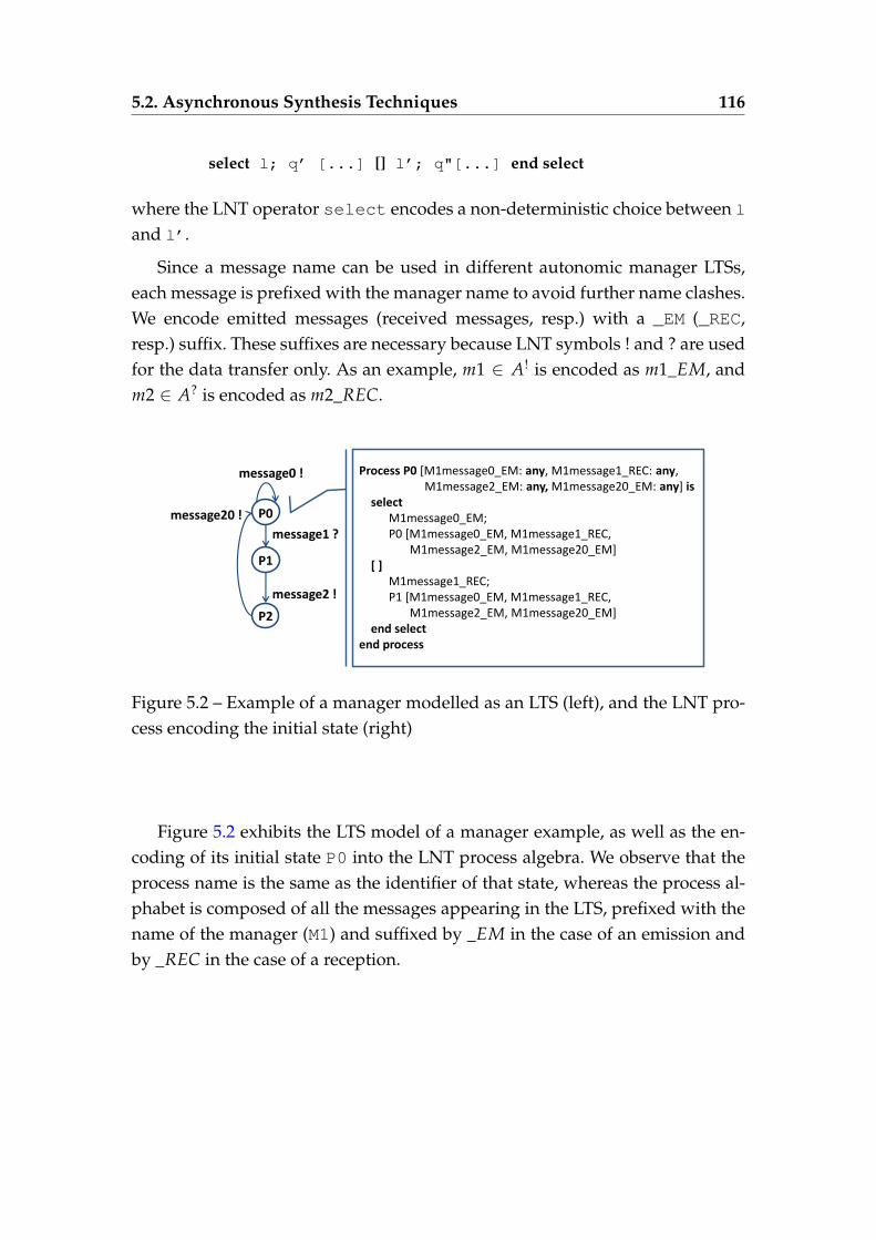
5.2. Asynchronous Synthesis Techniques 116
select l; q’ [...] [] l’; q"[...] end select
where the LNT operator select encodes a non-deterministic choice between l
and l’.
Since a message name can be used in different autonomic manager LTSs,each message is prefixed with the manager name to avoid further name clashes.We encode emitted messages (received messages, resp.) with a _EM (_REC,resp.) suffix. These suffixes are necessary because LNT symbols ! and ? are usedfor the data transfer only. As an example, m1 ∈ A! is encoded as m1_EM, andm2 ∈ A? is encoded as m2_REC.
message0 !
message1 ?
message2 !
message20 !
Process P0 [M1message0_EM: any, M1message1_REC: any, M1message2_EM: any, M1message20_EM: any] is select M1message0_EM; P0 [M1message0_EM, M1message1_REC, M1message2_EM, M1message20_EM] [ ] M1message1_REC; P1 [M1message0_EM, M1message1_REC, M1message2_EM, M1message20_EM] end select end process
P0
P1
P2
Figure 5.2 – Example of a manager modelled as an LTS (left), and the LNT pro-cess encoding the initial state (right)
Figure 5.2 exhibits the LTS model of a manager example, as well as the en-coding of its initial state P0 into the LNT process algebra. We observe that theprocess name is the same as the identifier of that state, whereas the process al-phabet is composed of all the messages appearing in the LTS, prefixed with thename of the manager (M1) and suffixed by _EM in the case of an emission andby _REC in the case of a reception.
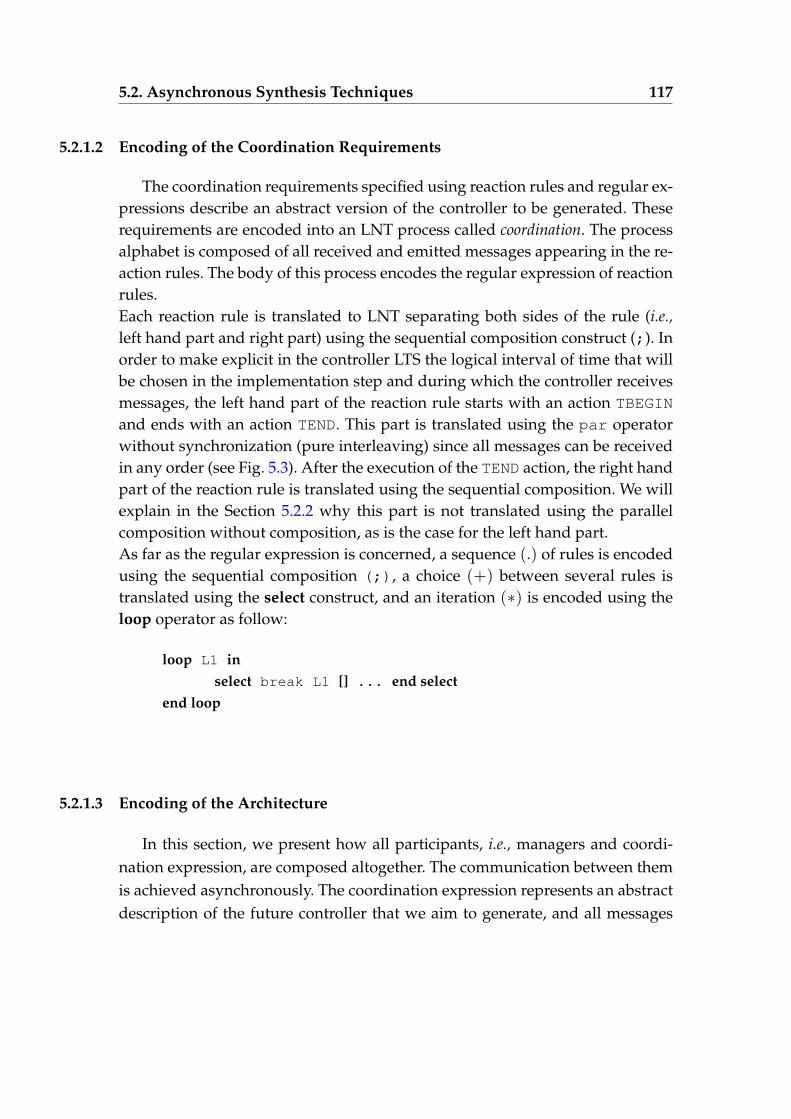
5.2. Asynchronous Synthesis Techniques 117
5.2.1.2 Encoding of the Coordination Requirements
The coordination requirements specified using reaction rules and regular ex-pressions describe an abstract version of the controller to be generated. Theserequirements are encoded into an LNT process called coordination. The processalphabet is composed of all received and emitted messages appearing in the re-action rules. The body of this process encodes the regular expression of reactionrules.Each reaction rule is translated to LNT separating both sides of the rule (i.e.,left hand part and right part) using the sequential composition construct (;). Inorder to make explicit in the controller LTS the logical interval of time that willbe chosen in the implementation step and during which the controller receivesmessages, the left hand part of the reaction rule starts with an action TBEGIN
and ends with an action TEND. This part is translated using the par operatorwithout synchronization (pure interleaving) since all messages can be receivedin any order (see Fig. 5.3). After the execution of the TEND action, the right handpart of the reaction rule is translated using the sequential composition. We willexplain in the Section 5.2.2 why this part is not translated using the parallelcomposition without composition, as is the case for the left hand part.As far as the regular expression is concerned, a sequence (.) of rules is encodedusing the sequential composition (;), a choice (+) between several rules istranslated using the select construct, and an iteration (∗) is encoded using theloop operator as follow:
loop L1 inselect break L1 [] ... end select
end loop
5.2.1.3 Encoding of the Architecture
In this section, we present how all participants, i.e., managers and coordi-nation expression, are composed altogether. The communication between themis achieved asynchronously. The coordination expression represents an abstractdescription of the future controller that we aim to generate, and all messages
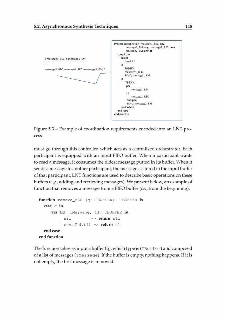
5.2. Asynchronous Synthesis Techniques 118
Process coordination [message1_REC: any, message1_EM: any, message2_REC: any, message2_EM: any] is Loop L1 in select break L1 [] TBEGIN; message1_REC; TEND; message1_EM [] TBEGIN; par message2_REC || message1_REC end par; TEND; message2_EM end select end loop end process
( message1_REC -> message1_EM
+
message2_REC, message1_REC ->message2_EM) *
Figure 5.3 – Example of coordination requirements encoded into an LNT pro-cess
must go through this controller, which acts as a centralized orchestrator. Eachparticipant is equipped with an input FIFO buffer. When a participant wantsto read a message, it consumes the oldest message putted in its buffer. When itsends a message to another participant, the message is stored in the input bufferof that participant. LNT functions are used to describe basic operations on thesebuffers (e.g., adding and retrieving messages). We present below, an example offunction that removes a message from a FIFO buffer (i.e., from the beginning).
function remove_MSG (q: TBUFFER): TBUFFER iscase q in
var hd: TMessage, tl: TBUFFER innil -> return nil
| cons(hd,tl) -> return tl
end caseend function
The function takes as input a buffer (q), which type is (TBuffer) and composedof a list of messages (TMessage). If the buffer is empty, nothing happens. If it isnot empty, the first message is removed.
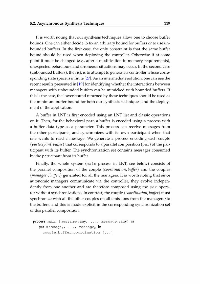
5.2. Asynchronous Synthesis Techniques 119
It is worth noting that our synthesis techniques allow one to choose bufferbounds. One can either decide to fix an arbitrary bound for buffers or to use un-bounded buffers. In the first case, the only constraint is that the same bufferbound should be used when deploying the controller. Otherwise if at somepoint it must be changed (e.g., after a modification in memory requirements),unexpected behaviours and erroneous situations may occur. In the second case(unbounded buffers), the risk is to attempt to generate a controller whose corre-sponding state space is infinite [27]. As an intermediate solution, one can use therecent results presented in [19] for identifying whether the interactions betweenmanagers with unbounded buffers can be mimicked with bounded buffers. Ifthis is the case, the lower bound returned by these techniques should be used asthe minimum buffer bound for both our synthesis techniques and the deploy-ment of the application.
A buffer in LNT is first encoded using an LNT list and classic operationson it. Then, for the behavioral part, a buffer is encoded using a process witha buffer data type as a parameter. This process can receive messages fromthe other participants, and synchronizes with its own participant when thatone wants to read a message. We generate a process encoding each couple(participant, buffer) that corresponds to a parallel composition (par) of the par-ticipant with its buffer. The synchronization set contains messages consumedby the participant from its buffer.
Finally, the whole system (main process in LNT, see below) consists ofthe parallel composition of the couple (coordination, buffer) and the couples(manageri, bufferi) generated for all the managers. It is worth noting that sinceautonomic managers communicate via the controller, they evolve indepen-dently from one another and are therefore composed using the par opera-tor without synchronizations. In contrast, the couple (coordination, buffer) mustsynchronize with all the other couples on all emissions from the managers/tothe buffers, and this is made explicit in the corresponding synchronization setof this parallel composition.
process main [message1:any, ..., messagen:any] ispar messagep, ..., messagek incouple_buffer_coordination [...]
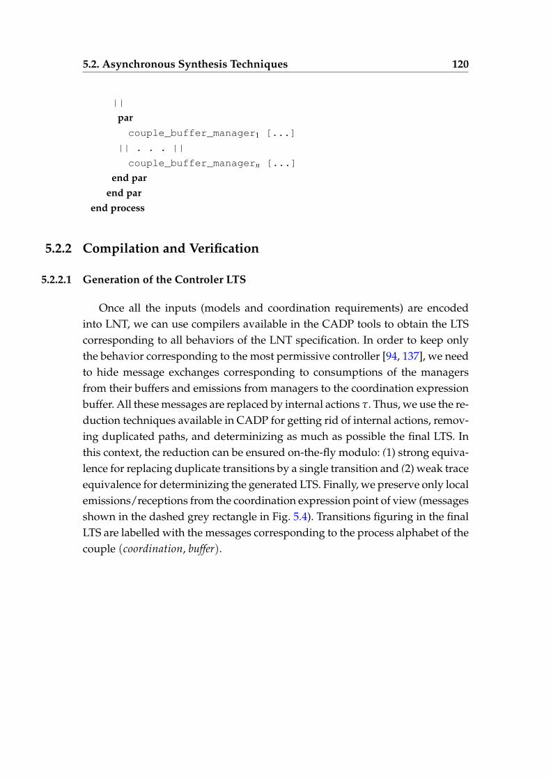
5.2. Asynchronous Synthesis Techniques 120
||
parcouple_buffer_manager1 [...]
|| . . . ||
couple_buffer_managern [...]
end parend par
end process
5.2.2 Compilation and Verification
5.2.2.1 Generation of the Controler LTS
Once all the inputs (models and coordination requirements) are encodedinto LNT, we can use compilers available in the CADP tools to obtain the LTScorresponding to all behaviors of the LNT specification. In order to keep onlythe behavior corresponding to the most permissive controller [94, 137], we needto hide message exchanges corresponding to consumptions of the managersfrom their buffers and emissions from managers to the coordination expressionbuffer. All these messages are replaced by internal actions τ. Thus, we use the re-duction techniques available in CADP for getting rid of internal actions, remov-ing duplicated paths, and determinizing as much as possible the final LTS. Inthis context, the reduction can be ensured on-the-fly modulo: (1) strong equiva-lence for replacing duplicate transitions by a single transition and (2) weak traceequivalence for determinizing the generated LTS. Finally, we preserve only localemissions/receptions from the coordination expression point of view (messagesshown in the dashed grey rectangle in Fig. 5.4). Transitions figuring in the finalLTS are labelled with the messages corresponding to the process alphabet of thecouple (coordination, buffer).
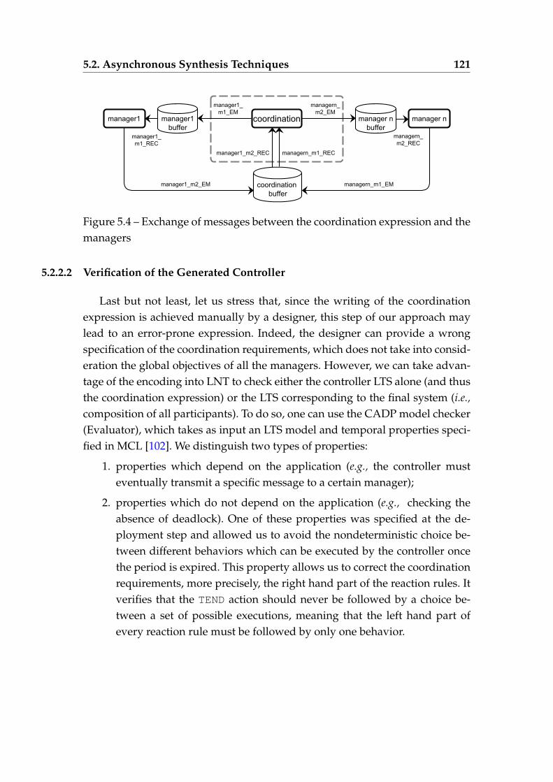
5.2. Asynchronous Synthesis Techniques 121
Figure 5.4 – Exchange of messages between the coordination expression and themanagers
5.2.2.2 Verification of the Generated Controller
Last but not least, let us stress that, since the writing of the coordinationexpression is achieved manually by a designer, this step of our approach maylead to an error-prone expression. Indeed, the designer can provide a wrongspecification of the coordination requirements, which does not take into consid-eration the global objectives of all the managers. However, we can take advan-tage of the encoding into LNT to check either the controller LTS alone (and thusthe coordination expression) or the LTS corresponding to the final system (i.e.,composition of all participants). To do so, one can use the CADP model checker(Evaluator), which takes as input an LTS model and temporal properties speci-fied in MCL [102]. We distinguish two types of properties:
1. properties which depend on the application (e.g., the controller musteventually transmit a specific message to a certain manager);
2. properties which do not depend on the application (e.g., checking theabsence of deadlock). One of these properties was specified at the de-ployment step and allowed us to avoid the nondeterministic choice be-tween different behaviors which can be executed by the controller oncethe period is expired. This property allows us to correct the coordinationrequirements, more precisely, the right hand part of the reaction rules. Itverifies that the TEND action should never be followed by a choice be-tween a set of possible executions, meaning that the left hand part ofevery reaction rule must be followed by only one behavior.
5.3. Java Code Generation and Deployment 122
5.3 Java Code Generation and Deployment
We present in this section our techniques to automatically generate the Javacode, which corresponds to the controller LTS obtained during the compilationphase (see Section 5.2.2). This Java code allows to deploy controllers in the con-text of real-world applications.
5.3.1 Java Code Generation Techniques
Our Java code generation techniques are based on the use of object-orientedprogramming. It take as input the controller LTS synthesized beforehand andautomatically generate all Java classes, methods, and types necessary for de-ploying it. The controller LTS is encoded as an instance of a Java class LTS.This class relies on two classes, namely a class State and a class Transition,which represents the transitions between the states. The LTS class also de-fines an attribute cstate representing the current active state in the controllermodel. This variable is initialized with the LTS initial state. Some Java codeis necessary to interface the controller with the running application. We par-ticularly define a method called react that takes as input a list of messagesreceived within a period of time and applies successive moves according to thereceived messages, the current state of the controller, and the behavior of thegenerated controller. This method computes the messages that the controllerhas to send as a reaction to these received messages and updates the currentstate of the controller.
5.3.2 Deployment
Our generated Java code can be deployed and applied on concrete appli-cations using the event-based programming paradigm. The period of time de-scribed using special actions TBEGIN and TEND in the controller LTS has to beinstantiated with a real value. This period is computed using sampling tech-niques and implemented using the sleep method in Java. The choice of thisperiod cannot be realized during the synthesis phase and is achieved just be-
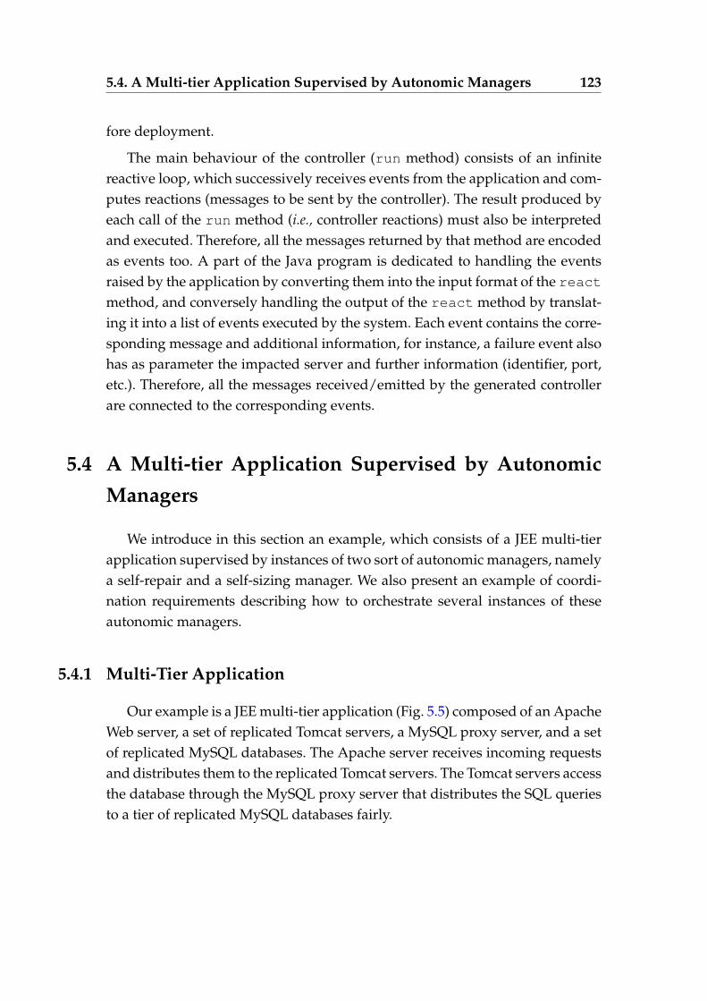
5.4. A Multi-tier Application Supervised by Autonomic Managers 123
fore deployment.
The main behaviour of the controller (run method) consists of an infinitereactive loop, which successively receives events from the application and com-putes reactions (messages to be sent by the controller). The result produced byeach call of the run method (i.e., controller reactions) must also be interpretedand executed. Therefore, all the messages returned by that method are encodedas events too. A part of the Java program is dedicated to handling the eventsraised by the application by converting them into the input format of the reactmethod, and conversely handling the output of the react method by translat-ing it into a list of events executed by the system. Each event contains the corre-sponding message and additional information, for instance, a failure event alsohas as parameter the impacted server and further information (identifier, port,etc.). Therefore, all the messages received/emitted by the generated controllerare connected to the corresponding events.
5.4 A Multi-tier Application Supervised by AutonomicManagers
We introduce in this section an example, which consists of a JEE multi-tierapplication supervised by instances of two sort of autonomic managers, namelya self-repair and a self-sizing manager. We also present an example of coordi-nation requirements describing how to orchestrate several instances of theseautonomic managers.
5.4.1 Multi-Tier Application
Our example is a JEE multi-tier application (Fig. 5.5) composed of an ApacheWeb server, a set of replicated Tomcat servers, a MySQL proxy server, and a setof replicated MySQL databases. The Apache server receives incoming requestsand distributes them to the replicated Tomcat servers. The Tomcat servers accessthe database through the MySQL proxy server that distributes the SQL queriesto a tier of replicated MySQL databases fairly.
5.4. A Multi-tier Application Supervised by Autonomic Managers 124
Figure 5.5 – A multi-tier application
5.4.2 The Managers Role
The dynamic sizing plays an important role in the energy consumption ofthe replicated hosted on this type of application. Varying the number of requestsmakes difficult the estimation of the number of duplicated servers when start-ing the application. Therefore, adjusting dynamically the degree of replicationallows to allocate only the number of needed servers according to the numberof requests. Moreover, once a server fails, the failure must be immediately de-tected and repaired in order to preserve the application consistency. To optimizethe energy consumption of the replicated servers and preserve the applicationconsistency, we used managers such as self-sizing and self-repair for the man-agement of the dynamic sizing and the servers repair of multi-tier applications.Figure 5.6 displays how the architecture of each one of these managers is basedon the MAPE-K (Monitor Analyse Plan Execute - Knowledge) reference model(see Section 2.4). For instance, the self-sizing manager continuously observes aload of replicated servers through the Monitor function. It computes the av-erage of the load and detects the presence of an overload or an under-loadthrough the Analyze function. Once an overload (under-load, resp.) is detected,the manager makes a decision about the addition or removal of a server throughthe Plan function. This decision is executed by the execute function.
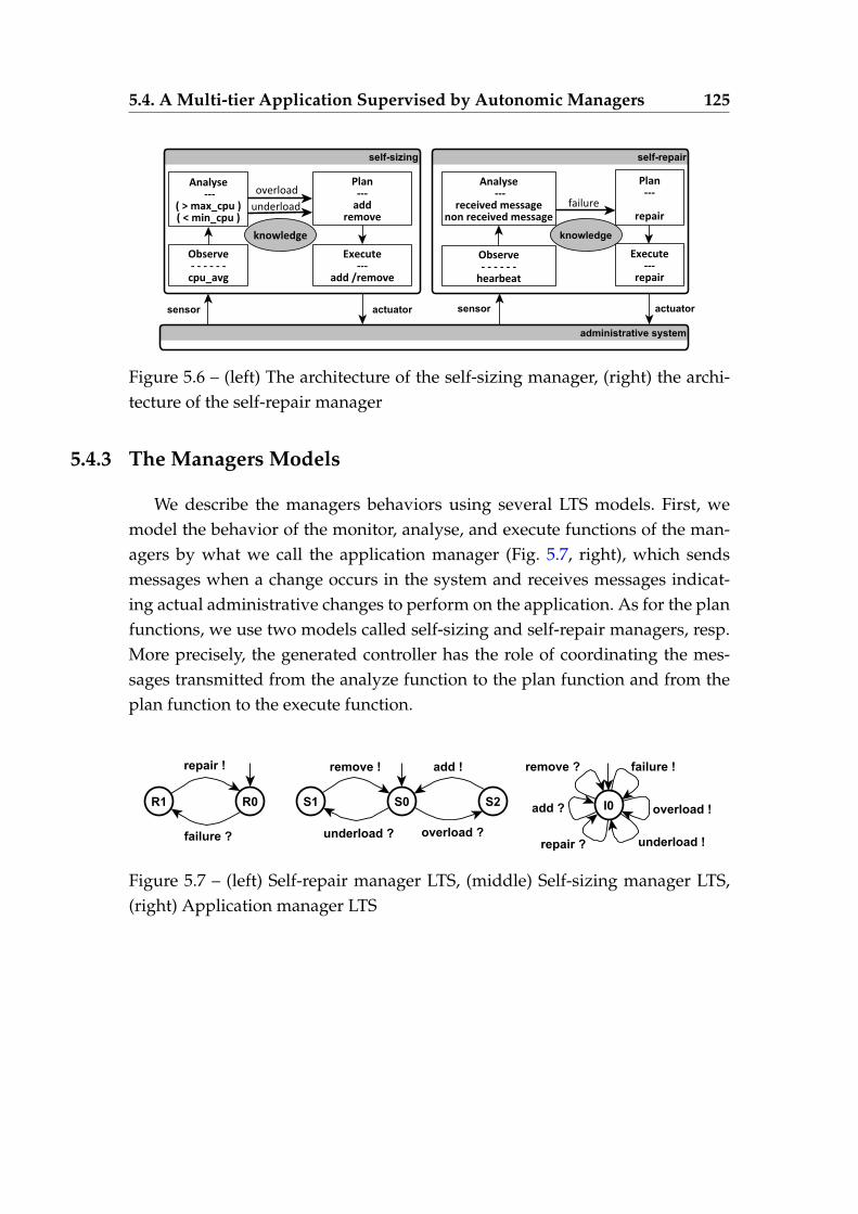
5.4. A Multi-tier Application Supervised by Autonomic Managers 125
Figure 5.6 – (left) The architecture of the self-sizing manager, (right) the archi-tecture of the self-repair manager
5.4.3 The Managers Models
We describe the managers behaviors using several LTS models. First, wemodel the behavior of the monitor, analyse, and execute functions of the man-agers by what we call the application manager (Fig. 5.7, right), which sendsmessages when a change occurs in the system and receives messages indicat-ing actual administrative changes to perform on the application. As for the planfunctions, we use two models called self-sizing and self-repair managers, resp.More precisely, the generated controller has the role of coordinating the mes-sages transmitted from the analyze function to the plan function and from theplan function to the execute function.
Figure 5.7 – (left) Self-repair manager LTS, (middle) Self-sizing manager LTS,(right) Application manager LTS
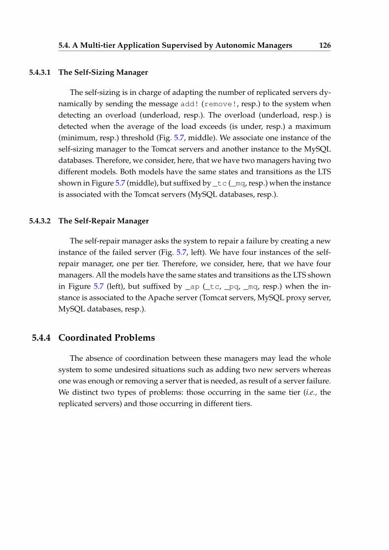
5.4. A Multi-tier Application Supervised by Autonomic Managers 126
5.4.3.1 The Self-Sizing Manager
The self-sizing is in charge of adapting the number of replicated servers dy-namically by sending the message add! (remove!, resp.) to the system whendetecting an overload (underload, resp.). The overload (underload, resp.) isdetected when the average of the load exceeds (is under, resp.) a maximum(minimum, resp.) threshold (Fig. 5.7, middle). We associate one instance of theself-sizing manager to the Tomcat servers and another instance to the MySQLdatabases. Therefore, we consider, here, that we have two managers having twodifferent models. Both models have the same states and transitions as the LTSshown in Figure 5.7 (middle), but suffixed by _tc (_mq, resp.) when the instanceis associated with the Tomcat servers (MySQL databases, resp.).
5.4.3.2 The Self-Repair Manager
The self-repair manager asks the system to repair a failure by creating a newinstance of the failed server (Fig. 5.7, left). We have four instances of the self-repair manager, one per tier. Therefore, we consider, here, that we have fourmanagers. All the models have the same states and transitions as the LTS shownin Figure 5.7 (left), but suffixed by _ap (_tc, _pq, _mq, resp.) when the in-stance is associated to the Apache server (Tomcat servers, MySQL proxy server,MySQL databases, resp.).
5.4.4 Coordinated Problems
The absence of coordination between these managers may lead the wholesystem to some undesired situations such as adding two new servers whereasone was enough or removing a server that is needed, as result of a server failure.We distinct two types of problems: those occurring in the same tier (i.e., thereplicated servers) and those occurring in different tiers.
5.4. A Multi-tier Application Supervised by Autonomic Managers 127
5.4.4.1 Coordinated Problems in the Same Tier
A failure of a server in a set of replicated servers triggers an overload ofthe remaining servers. Actually, when the self-repair manager receives a mes-sage indicating the detection of this failure, it sends a message to the applicationmanager requesting it to repair the failure by creating a new replica. Before com-pletion of this repair phase, the other replicated servers receive more requeststhan before the failure, which causes an overload. Upon reception of this over-load detection from the application manager, the self-sizing manager sends amessage back asking the addition of another server. In this scenario, as a resultof a server failure, two new servers are added to the application whereas onewas enough.
5.4.4.2 Coordinated Problems in Different Tiers
A failure of a server, which is hosted on a first tier and connected to otherservers hosted on another tier, triggers an under-load in the second tier. Actu-ally, when the self-repair manager receives a message indicating the detection ofthis failure, it sends a message to the application manager requesting it to repairthe failure by creating a new replica. Before completion of this reparation, theservers hosted on the second tier receive fewer requests than before the failure,which causes an under-load. Upon reception of this under-load detection fromthe application manager, the self-sizing manager sends a message back callingfor the removal of a server. Then, once the failed server is repaired, the servershosted on the second tier receive more requests than before the server repara-tion, which causes an overload and therefore the addition of another server bythe self-sizing manager. Therefore two unnecessary operations (i.e., the removaland the addition operations) are executed as a result of a server failure.
5.4.5 Managers Coordination
We present below an excerpt of the requirements for the controller we wantto generate for our example. These rules ensure that all managers globally sat-isfy the coordination objectives. Each line presents the actions that can be re-
5.4. A Multi-tier Application Supervised by Autonomic Managers 128
ceived by the controller in a period T (left parts of reactions rules). At the endof each period, if the received messages match the left part of one fireable rule,it reacts by emitting the messages appearing in the right part of that rule. Allmessages are prefixed by the manager name (app stands for the applicationmanager) and suffixed by the name of the tier to which is associated the man-ager.
( app_failure_ap? -> repair_failure_ap! (Ê)+ app_failure_tc? -> repair_failure_tc! (Ë)+ app_overload_tc? -> sizing_overload_tc! (Ì)+ app_underload_tc? -> sizing_underload_tc! (Í)+ app_failure_mysql? -> repair_failure_mysql! (Î)+ app_failure_px? -> repair_failure_px! (Ï)+ app_failure_ap?, app_underload_tc? -> repair_failure_ap! (Ð)+ app_failure_tc?, app_overload_tc? -> repair_failure_tc! (Ñ)+ ... ) *
We distinguish two kinds of rules:
1. those where a unique message appears in the left part of the reaction rule(see, e.g., Ê, Ë). In that case, the corresponding controller immediatelytransfers that message to the manager;
2. those encoding the coordination we want to impose on managers, e.g.,rule Ñ permits to generate a controller that can avoid to add two Tomcatservers by forwarding only one of the two received messages on a sameperiod of time.
Last, since there is no specific order between all these rules, we use a simpleregular expression where all rules can be fired at any time (combination of +and * operators).
5.4.6 Encoding into LNT
Let us first show some excerpts of LNT obtained when calling our LNTcode generator in this example. We first show the LNT processes encod-ing an instance of the repair manager, which handles the tier of the Tom-cat servers. The first process has the same name as the initial state identifier
5.4. A Multi-tier Application Supervised by Autonomic Managers 129
R0_tc. The process alphabet is the set of labels used in this manager LTS(repair_failure_tc_REC and repair_repairing_tc_EM). Each mes-sage is prefixed with the manager name. The body of the first process, for in-stance, receives a failure message (repair_Failure_tc_REC) and calls theprocess encoding the target state, that is R1_tc.
process R0_tc [repair_failure_tc_REC: any,repair_repairing_tc_EM: any] is
repair_failure_tc_REC;
R1_tc [repair_failure_tc_REC, repair_repairing_tc_EM]
end process
process R1_tc [repair_failure_tc_REC: any,repair_repairing_tc_EM: any] is
repair_repairing_tc_EM;
R0_tc [repair_failure_tc_REC, repair_repairing_tc_EM]
end process
We show now an example of process encoding a couple (manager, bu f f er),particularly the couple corresponding to the repair manager handling thetier of the Tomcat servers. This manager synchronizes with its buffer on therepair_failure_tc_REC message, which is emitted by the buffer and re-ceived by the manager. Note that the buffer process (buffer_repair_tc) isequipped with a parameter corresponding to the buffer data type, that is thestructure where messages are stored, initialized to nil.
process couple_buffer_repair_tc [repair_failure_tc_REC: any,repair_repairing_tc_EM: any, repair_failure_tc_EM: any] is
par repair_failure_tc_REC isR0_tc [repair_failure_tc_REC, repair_repairing_tc_EM]
||buffer_repair_tc [repair_failure_tc_EM, ...] (nil)
end parend process
After generating all the couples (autonomic manager/buffer, applicationmanager/buffer, and controller/ buffer), the main process is encoded using par-
5.4. A Multi-tier Application Supervised by Autonomic Managers 130
allel compositions. The managers do not interact directly together. Thereforetheir couples are translated using the par construct without synchronizations(pure interleaving). All the managers communicate together through the con-troller. This interaction is expressed using another parallel composition wherethe synchronization set makes explicit all emissions sent by the managers to thecontroller buffer, or sent by the controller to the managers buffers.
process main [repair_failure_ap_REC:any, ...] ispar sys_failure_ap_EM, sys_failure_tc_EM, ... in(* couple coordination/buffer *)
couple_buffer_coordinaiton [...]
||par(* couple application manager/buffer *)
couple_buffer_AM [...]
||(* couple repair manager/buffer for the Apache server*)
couple_buffer_repair_ap [...]
||(* couple repair manager/buffer for the Tomcat servers*)
couple_buffer_repair_tc [...]
||(* couple repair manager/buffer for the MySQL proxy server*)
couple_buffer_repair_px [...]
||(* couple repair manager/buffer for the MySQl databases*)
couple_buffer_repair_mq [...]
||(* couple sizing manager/buffer for the Tomcat server *)
couple_buffer_sizing_tc [...]
||(* couple sizing manager/buffer for the MySQL databases *)
couple_buffer_sizing_mq [...]
end parend par
end process
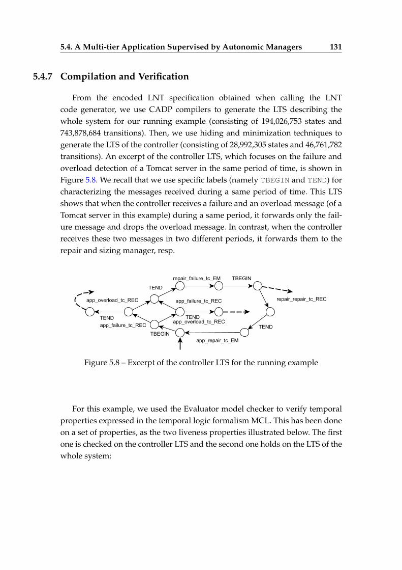
5.4. A Multi-tier Application Supervised by Autonomic Managers 131
5.4.7 Compilation and Verification
From the encoded LNT specification obtained when calling the LNTcode generator, we use CADP compilers to generate the LTS describing thewhole system for our running example (consisting of 194,026,753 states and743,878,684 transitions). Then, we use hiding and minimization techniques togenerate the LTS of the controller (consisting of 28,992,305 states and 46,761,782transitions). An excerpt of the controller LTS, which focuses on the failure andoverload detection of a Tomcat server in the same period of time, is shown inFigure 5.8. We recall that we use specific labels (namely TBEGIN and TEND) forcharacterizing the messages received during a same period of time. This LTSshows that when the controller receives a failure and an overload message (of aTomcat server in this example) during a same period, it forwards only the fail-ure message and drops the overload message. In contrast, when the controllerreceives these two messages in two different periods, it forwards them to therepair and sizing manager, resp.
Figure 5.8 – Excerpt of the controller LTS for the running example
For this example, we used the Evaluator model checker to verify temporalproperties expressed in the temporal logic formalism MCL. This has been doneon a set of properties, as the two liveness properties illustrated below. The firstone is checked on the controller LTS and the second one holds on the LTS of thewhole system:
5.4. A Multi-tier Application Supervised by Autonomic Managers 132
— The reception of a failure message by the controller is eventually fol-lowed by an emission of a repair message to the application managerin order to ask it to repair the Tomcat server
[true* .app_failure_tc_REC] inev (app_repair_tc_EM)
— The emission of an overload message by the application manager is even-tually followed by an emission of a reparation or addition message by thecontroller
[true* .app_overload_tc_EM]
inev (app_repair_tc_EM or app_add_tc_EM)
This property shows that the overload message is handled by the repairmanager when both Tomcat failure and overload occur within a sameperiod of time. Otherwise, it is handled by the sizing manager.
Both properties use the macro inev (M), which is used especially when speci-fying liveness properties that are inevitability assertions. The inevitability asser-tions can be expressed using fixed point operators that indicate that a transitionlabelled with M eventually occurs. The inev macro is defined as follows:
macro inev (M) = mu X .( < true > true and [ not (M) ] X )
end macro
Our approach was applied for validation purposes on many illustrativeexamples of our dataset (managers and coordination requirements). Table 5.1summarizes some of our experiments. Each managed application used as inputis characterized using the number of managers and the coordination require-ments. We give the size of the LTS (states/transitions) of the whole system aswell as the controller LTS obtained after minimization (wrt. a strong and a weaktrace relations). The last column gives the overall time to synthesize the con-troller.
We observe that, for some examples (gray lines), the size of the generatedcontroller LTSs and the time required for making those LTSs grow importantlywhen one of the managers exhibit looping behaviours, and particularly cycles
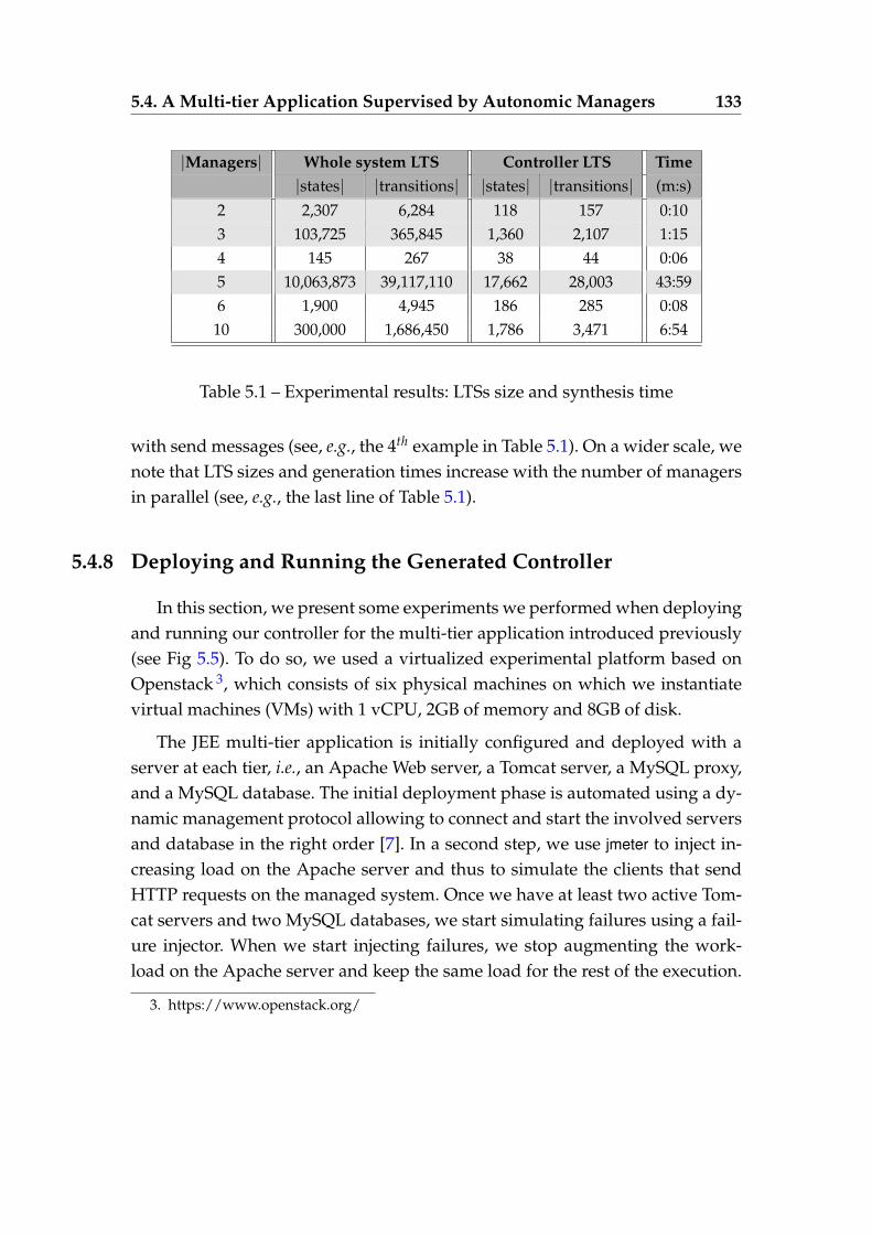
5.4. A Multi-tier Application Supervised by Autonomic Managers 133
|Managers| Whole system LTS Controller LTS Time|states| |transitions| |states| |transitions| (m:s)
2 2,307 6,284 118 157 0:103 103,725 365,845 1,360 2,107 1:154 145 267 38 44 0:065 10,063,873 39,117,110 17,662 28,003 43:596 1,900 4,945 186 285 0:08
10 300,000 1,686,450 1,786 3,471 6:54
Table 5.1 – Experimental results: LTSs size and synthesis time
with send messages (see, e.g., the 4th example in Table 5.1). On a wider scale, wenote that LTS sizes and generation times increase with the number of managersin parallel (see, e.g., the last line of Table 5.1).
5.4.8 Deploying and Running the Generated Controller
In this section, we present some experiments we performed when deployingand running our controller for the multi-tier application introduced previously(see Fig 5.5). To do so, we used a virtualized experimental platform based onOpenstack 3, which consists of six physical machines on which we instantiatevirtual machines (VMs) with 1 vCPU, 2GB of memory and 8GB of disk.
The JEE multi-tier application is initially configured and deployed with aserver at each tier, i.e., an Apache Web server, a Tomcat server, a MySQL proxy,and a MySQL database. The initial deployment phase is automated using a dy-namic management protocol allowing to connect and start the involved serversand database in the right order [7]. In a second step, we use jmeter to inject in-creasing load on the Apache server and thus to simulate the clients that sendHTTP requests on the managed system. Once we have at least two active Tom-cat servers and two MySQL databases, we start simulating failures using a fail-ure injector. When we start injecting failures, we stop augmenting the work-load on the Apache server and keep the same load for the rest of the execution.
3. https://www.openstack.org/
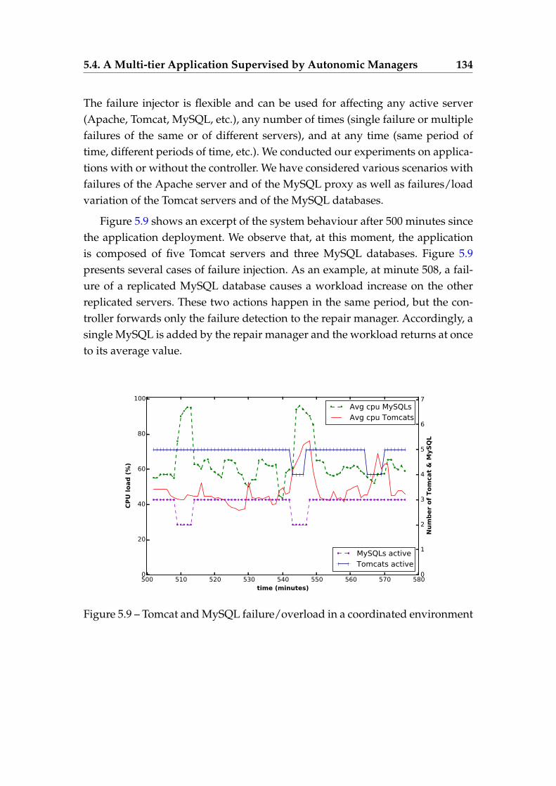
5.4. A Multi-tier Application Supervised by Autonomic Managers 134
The failure injector is flexible and can be used for affecting any active server(Apache, Tomcat, MySQL, etc.), any number of times (single failure or multiplefailures of the same or of different servers), and at any time (same period oftime, different periods of time, etc.). We conducted our experiments on applica-tions with or without the controller. We have considered various scenarios withfailures of the Apache server and of the MySQL proxy as well as failures/loadvariation of the Tomcat servers and of the MySQL databases.
Figure 5.9 shows an excerpt of the system behaviour after 500 minutes sincethe application deployment. We observe that, at this moment, the applicationis composed of five Tomcat servers and three MySQL databases. Figure 5.9presents several cases of failure injection. As an example, at minute 508, a fail-ure of a replicated MySQL database causes a workload increase on the otherreplicated servers. These two actions happen in the same period, but the con-troller forwards only the failure detection to the repair manager. Accordingly, asingle MySQL is added by the repair manager and the workload returns at onceto its average value.
500 510 520 530 540 550 560 570 580time (minutes)
0
20
40
60
80
100
CP
U load
(%
)
Avg cpu MySQLsAvg cpu Tomcats
0
1
2
3
4
5
6
7
Nu
mb
er
of
Tom
cat
& M
yS
QL
MySQLs activeTomcats active
Figure 5.9 – Tomcat and MySQL failure/overload in a coordinated environment
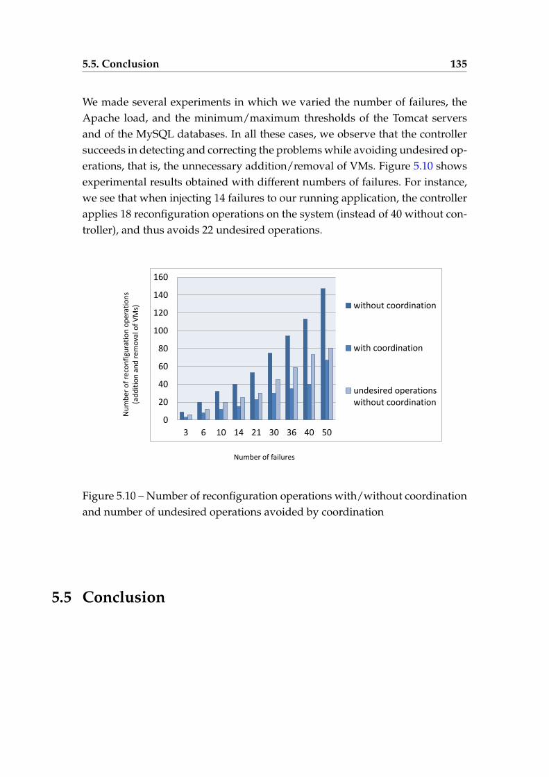
5.5. Conclusion 135
We made several experiments in which we varied the number of failures, theApache load, and the minimum/maximum thresholds of the Tomcat serversand of the MySQL databases. In all these cases, we observe that the controllersucceeds in detecting and correcting the problems while avoiding undesired op-erations, that is, the unnecessary addition/removal of VMs. Figure 5.10 showsexperimental results obtained with different numbers of failures. For instance,we see that when injecting 14 failures to our running application, the controllerapplies 18 reconfiguration operations on the system (instead of 40 without con-troller), and thus avoids 22 undesired operations.
0
20
40
60
80
100
120
140
160
3 6 10 14 21 30 36 40 50
without coordination
with coordination
undesired operations without coordination
Nu
mb
er o
f re
con
figu
rati
on
op
erat
ion
s (a
dd
itio
n a
nd
rem
ova
l of
VM
s)
Number of failures
Figure 5.10 – Number of reconfiguration operations with/without coordinationand number of undesired operations avoided by coordination
5.5 Conclusion
5.5. Conclusion 136
We have shown in this chapter new asynchronous synthesis techniques forgenerating a controller allowing to monitor and orchestrate the reconfigura-tion operations executed by several autonomic managers in the context of cloudapplications. The generated controller interacts asynchronously with the man-agers, which are regarded as control loops that react to events and changes byautomatically reconfiguring the application, via FIFO buffers and allows themto take globally coherent decisions in order to deal with control and incoher-ent decisions problems. The chapter presents also some Java code generationtechniques that allows to quickly deploy the generated controller for real-worldapplications such as N-tier applications.This chapter shows how the approach covers the whole development processfrom an expression of the requirements to the final implementation and de-ployment of the synthesized controller, which helps to coordinate at runtimereal-world applications. In addition, these synthesis techniques can be used tocontrol other applications where components are modelled as LTSs and com-municate asynchronously. This is the case in application areas such as Web ser-vices, multi-agent systems, or hardware protocols.
6Conclusion
" He who is not contented with what he has, would not be contented with what hewould like to have. "
Socrates
Contents
6.1 Achievements . . . . . . . . . . . . . . . . . . . . . . . . . . . . . 138
6.2 Perspectives . . . . . . . . . . . . . . . . . . . . . . . . . . . . . . 140
6.1. Achievements 138
THis chapter summarizes the thesis contributions and perspectives. In a firststep, it concludes the major achievements of this thesis. Then, it points out,
for future work, some perspectives that have been identified for the dynamicreconfiguration protocol that we designed. Some areas of prospective futureresearch have been also identified for the improvement of the coordination re-quirements, which we specified for coordinating autonomic managers used forthe management of distributed cloud applications.
6.1 Achievements
This Ph.D. thesis research is part of the OpenCloudware project, which isinterested in building and providing an open software platform for the devel-opment of distributed applications that need to be deployed on multiple Cloudinfrastructures. Within this project, we have focused on the dynamic reconfig-uration of the software architecture of distributed applications at run-time andthe automation of the reconfiguration tasks.In the context of the OpenCloudware project, cloud applications are complexdistributed applications that consist of interconnected software componentsrunning on several virtual machines (VMs), located on remote physical servers.The deployment and the reconfiguration of these applications are regarded asvery complicated tasks, especially when one or multiple virtual machines failwhen achieving them. Hence, the cloud users need protocols that allow them todynamically reconfigure and manage their distributed applications.We have introduced in Chapter 4 the first contribution of this thesis. We spec-ified a novel protocol, which aims at dynamically reconfiguring distributedcloud applications and supporting multiple VM failures. The protocol enablesthe execution of reconfiguration operations, such as instantiating new VMs, de-stroying existing VMs, adding new components, and removing existing com-ponents. It also allows the resolution of dependencies among interconnectedcomponents by exchanging messages, (dis)connecting, starting, and stoppingcomponents in a specific order. The exchange of the messages between the vir-tual machines is ensured through a publish-subscribe communication media.Upon reception of reconfiguration operations, each machine reconfigures itself
6.1. Achievements 139
in a decentralized manner. Indeed, each machine is equipped with a recon-figuration agent. An agent connects/disconnects and starts/stops componentshosted on that machine in a defined order for preserving the application con-sistency. Namely, the application consistency is quite complicated due to thehigh parallelism degree of the protocol. We have also explained how the pro-tocol is robust, fault-tolerant, and reconfiguration operations always terminatesuccessfully even in the presence of a finite number of failures. We specified theprotocol in a manner that it supports multiple virtual machine failures. Thus,it does not only detect VM failures but also repairs them by (i) creating newinstances of the failed VMs and (ii) notifying the other VMs of this failure.Furthermore, due to the high degree of parallelism inherent in this kind of ap-plications, we formally specified the protocol using the LNT value-passing pro-cess algebra. We also verified it using the model checking tools available in theCADP toolbox. This toolbox turned out to be very convenient for modeling andanalyzing such protocols, see [125] for a discussion about this subject. We ver-ified about 40 properties of interest, specified using MCL, on a large numberof application models and reconfiguration scenarios. More importantly, dur-ing these verification steps, the use of formal tools helped us to detect severalbugs and also to improve several parts of the protocol. In particular, we deeplyrevised the part of the protocol dedicated to the VM destruction and compo-nent shutdown. All these detected bugs have been corrected in the correspond-ing Java implementation, which has been established by another partner of theOpenCloudware project.
Another contribution of this thesis was to reduce the manual execution of thereconfiguration operations, which is a major challenge for cloud applications.Autonomic computing is a promising solution for monitoring and updating au-tomatically these kind of applications. This is achieved through the automationof administration functions and the use of autonomic managers. An autonomicmanager is regarded as a control loop. It observes the applications, detects spe-cific changes (such as the occurrence of a failure), and then reacts to them bydynamically reconfiguring the application. Multiple autonomic managers canbe implemented in the same system and must make consistent decisions. Usingthem without coordination may lead to inconsistencies and error-prone situa-tions. Thus, an important challenge is to use synthesis controller techniques in
6.2. Perspectives 140
order to generate a controller that aims at coordinating these managers.We have introduced in Chapter 5 new synthesis techniques that generate a cen-tralized controller. The particularity of these techniques is the asynchronous co-ordination of stateful autonomic managers through the generated controller. Wehave explained how the autonomic managers are modeled as LTSs. We also de-fined coordination requirements to describe the behavior of the controller weaim to generate. We specified these requirements using reaction rules and regu-lar expressions. The generated controller ensures proper reconfiguration of themanaged system. In fact, it coordinates the autonomic managers and communi-cates with them asynchronously using message passing via FIFO buffers. Oursolution for controller synthesis relies on an encoding of our models and thecoordination requirements into the LNT process algebra. From this encoding,an LTS can be generated using CADP compilers, hiding, and reduction tech-niques. This LTS exhibits all the possible executions of the controller. In thispart of work, we have taken advantage of this encoding to validate the gener-ated controller with the CADP verification tools, such as the Evaluator modelchecker. Indeed, since coordination requirements are written by a human being,they can be erroneous, which results in that case in an incorrect controller aswell. Finally, we proposed code generation techniques to automatically obtainthe Java code corresponding to the controller LTS. We validated our approachwith many variants of the multi-tier Web application we presented as an ex-ample at the end of Chapter 5. Our approach covers all the development stepsfrom the design of the coordination requirements to the actual deployment ofthe synthesized controller, which helps to coordinate at runtime real-world ap-plications. We note that the generated controller can be used to control otherapplications where components are modeled as LTSs and communicate asyn-chronously. This is the case in application areas such as Web services, multi-agent systems, or hardware protocols.
6.2 Perspectives
The thesis achievements present multiple research directions for futurework. This section successively describes perspectives to address the short-
6.2. Perspectives 141
comings of our contributions, addressing the dynamic reconfiguration of dis-tributed cloud applications. Then, it presents some research directions leverag-ing our contributions to coordinate several autonomic managers in the cloud.
— In Chapter 4, we presented an abstraction of a model for distributedcloud applications, which is expressive enough for reconfiguration pur-poses. It is used for verifying the soundness of the protocol, but its pri-mary role is to keep track of the VMs and components currently presentin the application. However, it should be enhanced for other tasks.This model can be enriched with more details to deal with the quality ofservice associated with the resources. We plan to add further informationto the model, such as resources availability and response time.
— In this thesis, we specified over 600 application models and reconfigura-tion scenarios in order to extensively validate our novel dynamic proto-col. When achieving these tasks, we paid much attention to cover verydifferent applications and scenarios, in particular pathological and cor-ner cases. Hence, this large investment in validation makes us highlyconfident in the correctness of the protocol.This work needs to be generalized by correctness proof. To solve thesegaps, proving the correctness of the protocol using theorem proving tech-niques would be a very interesting objective. This would complementthe validation of the reconfiguration protocol using model checking tech-niques presented in this thesis.
— We presented in Chapter 5 a new controller synthesis techniques for co-ordinating multiple autonomic managers. These techniques are based ona set of reaction rules and regular expressions allowing to specify howthe involved managers are supported to interact together. However, thecoordination expressions do not provide the ability to specify concurrentflows (e.g., by means of fork/join operators), which are quite common inorchestration and distributed coordination. Furthermore, our coordina-tion expressions can not describe specific requirements (e.g., elastic be-haviors with oscillations or cool-down periods). Expressing this type ofrequirements require the extension of our coordination expressions andLTS model by data-awareness and real-time constraints. When numeri-cal values, specific constraints, and requirements are added, these may,
6.2. Perspectives 142
however, lead to large state-space problems, especially when addressingmore complicated applications with an important number of involvedmanagers.Thus, some improvements are considered to integrate numerical valueswhen describing the behavior one expects from the controller we want togenerate. The enrichment of the requirements by these values allows toexpress specific constraints, such as a maximum/minimum permissiblenumber of servers to a tier of replicated servers. In this view, we will alsostudy further how to enhance the coordination expressions with morespecific requirements (e.g., bounds on resource usages and actuation de-lays) to manage complex cloud applications. Last but not least, to tacklethe state space problems, we plan to integrate techniques available in themodel checking, such as the Symbolic Model Checking with OBDDs andPartial Order Reduction [48].
— In this thesis, we also propose new controller synthesis techniques togenerate a centralized controller for distributed cloud applications. Thiscontroller allows us to orchestrate a set of autonomic managers. Nonethe-less, coordinating managers on a distributed infrastructure would ratherrequire a distributed choreography.The generation of distributed controllers instead of a centralized con-troller would be an ambitious future work. This is required in order tocontrol the system and exchange messages without passing through aunique centralized controller, while preserving the degree of parallelismof the system.
— Last but not least, in this thesis, we use the controller LTS synthesizedby our synthesis techniques to automatically generate all the Java codesfor deploying it. However, for some reason there may have a need tomodify the coordination requirements during the controller execution.In that case, our controller synthesis techniques should generate the newcontroller we want to deploy.We will study further how to incorporate changes in the deployed con-troller and update them while they are running, without stopping andrestarting them.
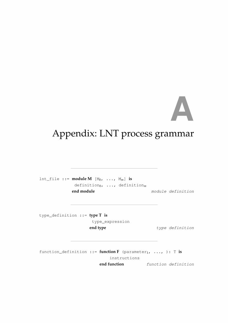
AAppendix: LNT process grammar
lnt_file ::= module M [M0, ..., Mm] isdefinition0, ..., definitionm
end module module definition
type_definition ::= type T istype_expression
end type type definition
function_definition ::= function F (parameter1, ..., ): T isinstructions
end function function definition
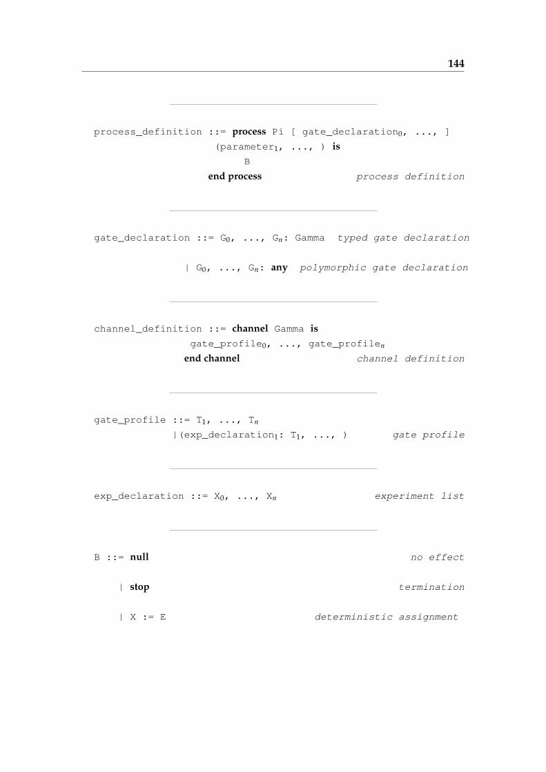
144
process_definition ::= process Pi [ gate_declaration0, ..., ]
(parameter1, ..., ) isB
end process process definition
gate_declaration ::= G0, ..., Gn: Gamma typed gate declaration
| G0, ..., Gn: any polymorphic gate declaration
channel_definition ::= channel Gamma isgate_profile0, ..., gate_profilen
end channel channel definition
gate_profile ::= T1, ..., Tn
|(exp_declaration1: T1, ..., ) gate profile
exp_declaration ::= X0, ..., Xn experiment list
B ::= null no effect
| stop termination
| X := E deterministic assignment
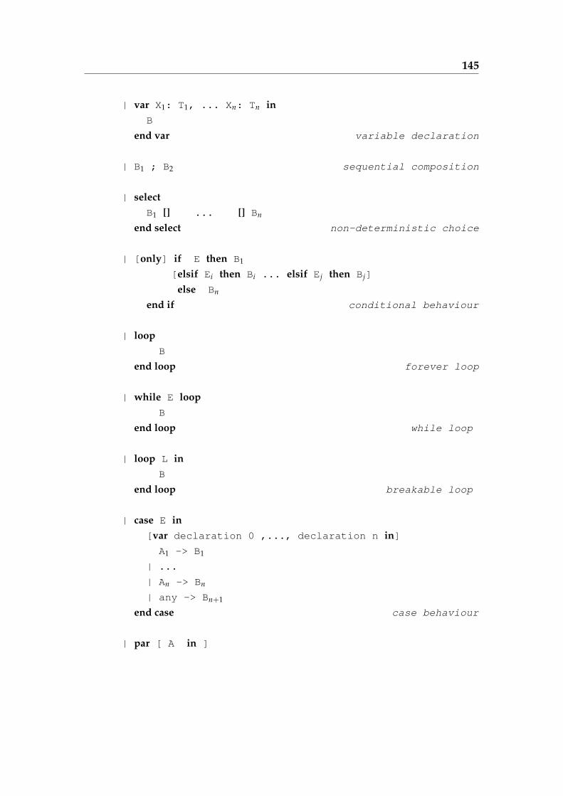
145
| var X1: T1, ... Xn: Tn inB
end var variable declaration
| B1 ; B2 sequential composition
| selectB1 [] ... [] Bn
end select non-deterministic choice
| [only] if E then B1
[elsif Ei then Bi ... elsif Ej then Bj]
else Bn
end if conditional behaviour
| loopB
end loop forever loop
| while E loopB
end loop while loop
| loop L inB
end loop breakable loop
| case E in[var declaration 0 ,..., declaration n in]
A1 -> B1
| ...
| An -> Bn
| any -> Bn+1
end case case behaviour
| par [ A in ]
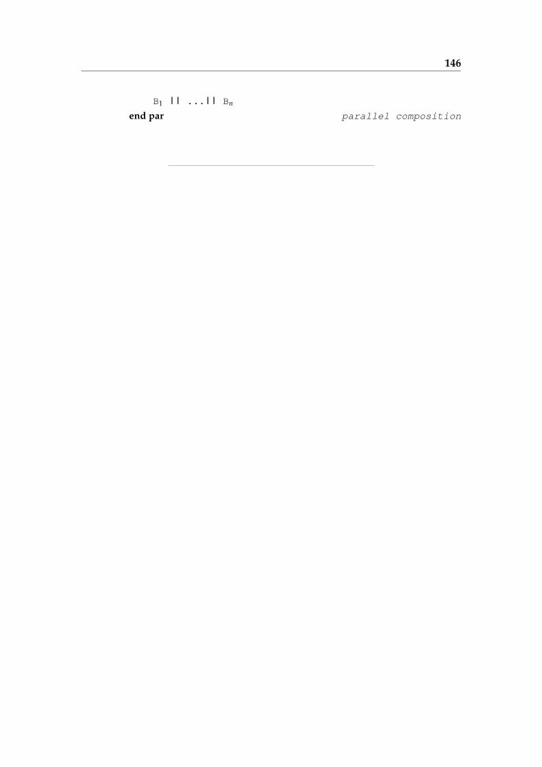
146
B1 || ...|| Bn
end par parallel composition
Bibliography
[1] Amazon EC2. 19
[2] AWS GovCloud (US) Region - Government Cloud Computing. 19
[3] HIPAA-Compliant Cloud Storage. 18
[4] Isabelle: Generic Proof Assistant. 26
[5] Public vs. Private Cloud Computing. 18
[6] The Coq Proof Assistant. 26
[7] R. Abid, G. Salaün, F. Bongiovanni, and N. De Palma. Verification of a Dy-namic Management Protocol for Cloud Applications. In Proc. of ATVA’13,volume 8172 of LNCS, pages 178–192, Hanoi, Vietnam, 2013. Springer. 133
[8] N. Aguirre and T. Maibaum. A Logical Basis for the Specification of Re-configurable Component-based Systems. In Proc. of FASE’03, FASE’03,pages 37–51, Warsaw, Poland, 2003. Springer-Verlag. 37
[9] R. Allen, R. Douence, and D. Garlan. Specifying and Analyzing DynamicSoftware Architectures. In Proc. of FASE’98, volume 1382 of LNCS, pages21–37, Lisbon, Portugal, 1998. Springer Berlin Heidelberg. 37
[10] R. Allen, R. Douence, and D. Garlan. Specifying and Analyzing DynamicSoftware Architectures. In Proc. of FASE’98, pages 21–37, Lisbon, Portugal,1998. 48
[11] R. Allen and D. Garlan. Formalizing Architectural Connection. In Work-shop. of ICSE’94, ICSE ’94, pages 71–80, Sorrento, Italy, 1994. IEEE Com-puter Society Press. 47
BIBLIOGRAPHY 148
[12] F. Arbab. The IWIM Model for Coordination of Concurrent Activities.In Proc. of COORDINATION ’96, COORDINATION ’96, pages 34–56, Ce-sena, Italy, 1996. Springer-Verlag. 54
[13] F. Arbab. What Do You Mean, Coordination? In Bulletin of the DutchAssociation for Theoretical Computer Science (NVTI), pages 11–22, 1998. 24
[14] F. Arbab. Reo: a Channel-Based Coordination Model for ComponentComposition. Mathematical Structures in Computer Science, 14(3):329–366,2004. 55
[15] F. Arbab, I. Herman, and P. Spilling. An Overview of Manifold and itsImplementation. Concurrency: Practice and Experience, 5(1):23–70, 1993. 25,54
[16] C. Attiogbé. Event-Based Approach to Modelling Dynamic Architecture:Application to Mobile Ad-Hoc Network. In Proc. of ISoLA’ 08, pages 769–781, Kassandra, Chalkidiki, Greece, 2008. 37
[17] C. Baier and J.P. Katoen. Principles of Model Checking. MIT Press, 2008. 30
[18] H.M.N. Dilum Bandara and A.P. Jayasumana. Collaborative Appli-cations over Peer-to-Peer Systems - Challenges and Solutions. CoRR,abs/1207.0790, 2012. 11
[19] S. Basu and T. Bultan. Automatic Verification of Interactions in Asyn-chronous Systems with Unbounded Buffers. In Proc. of ASE’14, pages743–754, Västeras, Sweden, 2014. ACM. 119
[20] G. Behrmann, A. David, and K.G. Larsen. A Tutorial on Uppaal. In Proc.of SFM’04, volume 3185 of LNCS, pages 200–236. Springer Berlin Heidel-berg, 2004. 27
[21] J. A. Bergstra and J. W. Klop. Process Algebra for Synchronous Commu-nication. Information and Control, 60(1-3):109–137, 1984. 28
[22] M. Bertier, O. Marin, and P. Sens. Implementation and Performance Eval-uation of an Adaptable Failure Detector. In Proc. of DSN’02, pages 354–363, Bethesda, Maryland, USA, 2002. IEEE Computer Society. 87
[23] K. Birman, R.V. Renesse, and W. Vogels. Adding High Availability andAutonomic Behavior to Web Services. In Proc. of ICSE’04, ICSE ’04, pages17–26, Scotland, UK, 2004. IEEE Computer Society. 70
BIBLIOGRAPHY 149
[24] A. H. Bond and L. Gasser. An Analysis of Problems and Research in DAI.Distributed Artificial Intelligence, 1988. 24
[25] F. Boyer, O. Gruber, and D. Pous. Robust Reconfigurations of ComponentAssemblies. In Proc. of ICSE’13, ICSE ’13, pages 13–22, Piscataway, NJ,USA, 2013. IEEE / ACM. 46
[26] F. Boyer, O. Gruber, and G. Salaün. Specifying and Verifying the SynergyReconfiguration Protocol with LOTOS NT and CADP. In Proc. of FM’11,volume 6664 of LNCS, pages 103–117, Limerick, Ireland, 2011. Springer.46
[27] D. Brand and P. Zafiropulo. On Communicating Finite-State Machines. J.ACM, 30(2):323–342, 1983. 119
[28] I. Brandic. Towards Self-Manageable Cloud Services. In Proc. of COMP-SAC’09, volume 2, pages 128–133. IEEE Computer Society, July 2009. 22
[29] A. Brogi, N. Busi, M. Gabbrielli, and G. Zavattaro. Comparative Analysisof the Expressiveness of Shared Dataspace Coordination. Electronic Notesin Theoretical Computer Science, 62:102–115, 2001. 53
[30] A. Brogi and P. Ciancarini. The Concurrent Language, Shared Prolog.ACM Trans. Program. Lang. Syst., 13(1):99–123, January 1991. 53
[31] S.D. Brookes, C.A.R. Hoare, and A.W. Roscoe. A Theory of Communicat-ing Sequential Processes. 31(3):560–599, June 1984. 28
[32] T. Bures, P. Hnetynka, and F. Plasil. SOFA 2.0: Balancing Advanced Fea-tures in a Hierarchical Component Model. In Proc. of SERA’06, pages 40–48, Seattle, Washington, Aug 2006. IEEE Computer Society. 37
[33] R. Buyya, R.N. Calheiros, and X. Li. Autonomic Cloud Computing: OpenChallenges and Architectural Elements. In Proc. of EAIT’12, pages 3–10.IEEE Computer Society, 2012. 23
[34] R. Buyya, S.Y. Chee, and S. Venugopal. Market-Oriented Cloud Comput-ing: Vision, Hype, and Reality for Delivering IT Services as ComputingUtilities. In Proc. of CCGRID ’09, pages 5–13, Shanghai, China, Sept 2009.IEEE Computer Society. 13, 14
[35] J. Camilleri. An Operational Semantics for Occam. International Journal ofParallel Programming, 18(5):365–400, 1989. 28
BIBLIOGRAPHY 150
[36] A. Cansado, C. Canal, G. Salaün, and J. Cubo. A Formal Framework forStructural Reconfiguration of Components under Behavioural Adapta-tion. Electr. Notes Theor. Comput. Sci., 263:95–110, 2010. 37
[37] J. Cao, A. Chan, Y. Sun, and K. Zhang. Dynamic Configuration Manage-ment in a Graph-Oriented Distributed Programming Environment. Sci.Comput. Program., 48(1):43–65, 2003. 11
[38] S. Carsten, K. Andreas, and K. Wolfgang. Formal Methods for the Valida-tion of Automotive Product Configuration Data. Artificial Intelligence forEngineering Design, Analysis and Manufacturing, 17:2003, 2003. 21
[39] C.G. Cassandras and S. Lafortune. Introduction to Discrete Event Systems.Springer-Verlag New York, Inc., Secaucus, NJ, USA, 2006. 63
[40] M. Catan, R. Di Cosmo, A. Eiche, T. A Lascu, M. Lienhardt, J. Mauro,R. Treinen, S. Zacchiroli, G. Zavattaro, and J. Zwolakowski. Aeolus: Mas-tering the Complexity of Cloud Application Deployment. In Proc. of ES-OCC’13, volume 8135 of LNCS, pages 1–3, Malaga, Spain, 2013. Springer.44
[41] D. Champelovier, X. Clerc, H. Garavel, Y. Guerte, F. Lang, C.Mckinty,V. Powazny, W. Serwe, and G. Smeding. Reference Manual of the LO-TOS NT to LOTOS Translator (Version 6.2). INRIA/VASY - INRIA/CON-VECS, 2015. 32
[42] D. Champelovier, X. Clerc, H. Garavel, Y. Guerte, V. Powazny, F. Lang,W. Serwe, and G. Smeding. Reference Manual of the LOTOS NT to LO-TOS Translator (Version 5.4). INRIA/VASY, 2011. 28, 93
[43] B. Chapman, M. Haines, P. Mehrota, H. Zima, and J. Van Rosendale.Opus: A Coordination Language for Multidisciplinary Applications. Sci.Program., 6(4):345–362, October 1997. 53
[44] C. Chapman, W. Emmerich, F. Galán Márquez, S. Clayman, and A. Galis.Software Architecture Definition for On-demand Cloud Provisioning. InProc. of HPDC’10, pages 61–72, Chicago, Illinois, 2010. ACM Press. 40
[45] C. Chapman, W. Emmerich, F.G. Marquez, S. Clayman, and A. Galis. Elas-tic Service Definition in Computational Clouds. In Proc. of NOMS’10,pages 327–334, Osaka, Japan, 2010. IEEE. 13
BIBLIOGRAPHY 151
[46] I. Chopra and M. Singh. Analysing the Need for Autonomic Behaviourin Grid Computing. In Proc. of ICCAE’10, volume 1, pages 535–539, Feb2010. 21
[47] P. Ciancarini. PoliS: a Programming Model for Multiple Tuple Spaces. InC. Ghezzi and G. Roman, editors, workshop. of IWSSD ’91, pages 44–51,Como, Italy, 1991. IEEE Computer Society Press. 53
[48] E.M. Clarke, W. Klieber, M. Novácek, and P. Zuliani. Model Checking andthe State Explosion Problem. In B. Meyer and M. Nordio, editors, Toolsfor Practical Software Verification, volume 7682 of Lecture Notes in ComputerScience. Springer Berlin Heidelberg, 2012. 142
[49] CloudTweaks. The 4 Primary Cloud Deployment Models, 2012. 18
[50] R.H. Cobb and H.D. Mills. Engineering Software Under Statistical QualityControl. Software, IEEE, 7(6):45–54, Nov 1990. 26
[51] G. Coulouris, J. Dollimore, T. Kindberg, and G. Blair. Distributed Systems:Concepts and Design. Addison-Wesley Publishing Company, USA, 5th edi-tion, 2011. 12
[52] P. Cousot, R. Cousot, J. Feret, L. Mauborgne, A. Mine, D. Monniaux, andX. Rival. The ASTREE Analyzer. In Mooly Sagiv, editor, Proc. of ESOP’ 05,volume 3444 of LNCS, pages 21–30, Edinburgh, Scotland, 2005. SpringerBerlin Heidelberg. 26
[53] R. Das, J.O. Kephart, C. Lefurgy, G. Tesauro, D.W. Levine, and H. Chan.Autonomic Multi-agent Management of Power and Performance in DataCenters. In Proc. of AAMAS ’08, pages 107–114, Estoril, Portugal, 2008. In-ternational Foundation for Autonomous Agents and Multiagent Systems.58
[54] G. Delaval, S.M.K. Gueye, É. Rutten, and N. De Palma. Modular Coordi-nation of Multiple Autonomic Managers. In Proc. of CBSE’14, pages 3–12,Lille, France, 2014. ACM. 65
[55] G. Delaval, H. Marchand, and É. Rutten. Contracts for Modular DiscreteController Synthesis. In Proc. of LCTES’10, pages 57–66, Stockholm, Swe-den, 2010. ACM. 64
BIBLIOGRAPHY 152
[56] A. Eastwood. Firm Fires Shots at Legacy Systems. Computing Canada,19(2):17, 1993. 12
[57] P. Emanuelsson and U. Nilsson. A Comparative Study of Industrial StaticAnalysis Tools. Electron. Notes Theor. Comput. Sci., 217:5–21, July 2008. 26
[58] L. Erlikh. Leveraging Legacy System Dollars for E-Business. IT Profes-sional, 2(3):17–23, May 2000. 12
[59] X. Etchevers, T. Coupaye, F. Boyer, and N. De. Palma. Self-Configurationof Distributed Applications in the Cloud. In Proc. of CLOUD’11, pages668–675, Washington DC, USA, 2011. IEEE Computer Society. 43
[60] X. Etchevers, T. Coupaye, F. Boyer, N. De Palma, and G. Salaün. Au-tomated Configuration of Legacy Applications in the Cloud. In Proc. ofUCC’11, pages 170–177, Melbourne, Australia, 2011. IEEE Computer So-ciety. 5, 43
[61] X. Etchevers, G. Salaün, F. Boyer, T. Coupaye, and N. De Palma. ReliableSelf-Deployment of Cloud Applications. In Proc. of SAC’14, pages 1331–1338, Gyeongju, Korea, 2014. ACM Press. 43
[62] J. Fischer, R. Majumdar, and S. Esmaeilsabzali. Engage: A DeploymentManagement System. In Proc. of PLDI’12, pages 263–274, Beijing, China,2012. ACM. 5, 41
[63] H. Garavel, F. Lang, and R. Mateescu. Compositional Verification of Asyn-chronous Concurrent Systems using CADP (extended version). ResearchReport RR-8708, INRIA Grenoble - Rhône-Alpes, Apr 2015. 28
[64] H. Garavel, F. Lang, R. Mateescu, and W. Serwe. CADP 2011: A Toolboxfor the Construction and Analysis of Distributed Processes. InternationalJournal on Software Tools for Technology Transfer, 15(2):89–107, 2013. 27, 28,94
[65] J. GEELAN. Twenty One Experts Define Cloud Computing. Virtualiza-tion, Electronic Magazine, 2008. 13, 14
[66] D. Gelernter. Generative Communication in Linda. ACM Trans. Program.Lang. Syst., 7(1):80–112, January 1985. 25
[67] D. Gelernter and N. Carriero. Coordination Languages and Their Signifi-cance. ACM Computing Surveys, 35(2):97–107, February 1992. 24
BIBLIOGRAPHY 153
[68] D. Giannakopoulou, J. Kramer, and S.C. Cheung. Behaviour Analysis ofDistributed Systems Using the Tracta Approach. Automated Software En-gineering, 6(1):7–35, January 1999. 37, 49
[69] P. Goldsack, J. Guijarro, S. Loughran, A. Coles, A. Farrell, A. Lain, P. Mur-ray, and P. Toft. The SmartFrog Configuration Management Framework.SIGOPS Oper. Syst. Rev., 43(1):16–25, 2009. 38
[70] H. Gomaa and M. Hussein. Software Reconfiguration Patterns for Dy-namic Evolution of Software Architectures. In Proc. of WICSA’04, pages79–88, Oslo, NORWAY, June 2004. IEEE Computer Society. 37
[71] E. Griffith. What Is Cloud Computing? , 2015. 13, 15
[72] J.F. Groote and A. Ponse. Proof Theory for µCRL: A Language for Pro-cesses with Data. In D.J. Andrews, J.F. Groote, and C.A. Middelburg, edi-tors, Semantics of Specification Languages (SoSL), Workshops in Computing,pages 232–251. Springer London, 1994. 28
[73] The Open Group. Cloud Computing Portability and Interoperability :Cloud Portability and Interoperability, 2013. 11
[74] S.M.K. Gueye, N. De Palma, É. Rutten, and A. Tchana. Coordinating Mul-tiple Administration Loops Using Discrete Control. SIGOPS Oper. Syst.Rev., 47(3):18–25, 2013. 65
[75] S.M.K. Gueye, É. Rutten, and A.Tchana. Discrete Control for the Coor-dination of Administration Loops. In Proc. of UCC’12, pages 353–358,Chicago, Illinois, USA, 2012. IEEE Computer Society. 65
[76] S. Hassan, D. Al-Jumeily, and A.J. Hussain. Autonomic ComputingParadigm to Support System’s Development. In Proc. of DESE’09, pages273–278. IEEE, Dec 2009. 21
[77] C.L. Heitmeyer. Formal Methods for Specifying, Validating, and VerifyingRequirements. jucs, 13(5):607–618, May 2007. 25
[78] G.J. Holzmann. The Model Checker SPIN. IEEE Trans. Softw. Eng.,23(5):279–295, May 1997. 27
[79] J. E. Hopcroft and J. D. Ullman. Introduction to Automata Theory, Languagesand Computation. Addison Wesley, 1979. 113
BIBLIOGRAPHY 154
[80] ISO/IEC. LOTOS — A Formal Description Technique Based on the Tem-poral Ordering of Observational Behaviour. International Standard 8807,International Organization for Standardization — Information ProcessingSystems — Open Systems Interconnection, 1989. 28, 93
[81] C. Joubert and R. Mateescu. Distributed On-the-Fly Equivalence Check-ing. Electr. Notes Theor. Comput. Sci., 128(3):47–62, 2005. 29
[82] C. Judith et al. NASA Formal Methods Specification and Verification Guide-book for Software and Computer Systems, Volume I: Planning and TechnologyInsertion. NASA Office of Safety and Mission Assurance, Washington,DC, 1995. 25
[83] S. Kätker and K. Geihs. Fault management in QoS-enabled distributedsystems. In Proc. of DAIS’99, pages 3–16, Ronneby, Sweden, 1999. 11
[84] J.O. Kephart. Research Challenges of Autonomic Computing. In Proc. ofICSE’05, pages 15–22. ACM, 2005. 22
[85] J.O. Kephart and D.M. Chess. The Vision of Autonomic Computing. Com-puter, 36(1):41–50, Jan 2003. 21, 22
[86] T. Kielmann. Designing a Coordination Model for Open systems. InP. Ciancarini and C. Hankin, editors, Proc. of Coordination’96, volume 1061of LNCS, pages 267–284. Springer Berlin Heidelberg, 1996. 53
[87] J. Koehler, C. Giblin, D. Gantenbein, and R. Hauser. On Autonomic Com-puting Architectures. Technical report, IBM Zurich Research Laboratory,2003. 22
[88] J. Kramer and J. Magee. Analysing Dynamic Change in Distributed Soft-ware Architectures. IEE Proceedings - Software, 145(5):146–154, 1998. 37,49
[89] C. Krause. Reconfigurable Component Connectors. PhD thesis, Institute forProgramming research and Algorithmics (IPA), 2011. 56
[90] C. Krause, Z. Maraikar, A. Lazovik, and F. Arbab. Modeling Dynamic Re-configurations in Reo Using High-Level Replacement Systems. Sci. Com-put. Program., 76(1):23–36, 2011. 37
BIBLIOGRAPHY 155
[91] T. A. Lascu, J. Mauro, and G. Zavattaro. Automatic Component Deploy-ment in the Presence of Circular Dependencies. In Proc. of FACS’13, vol-ume 8348 of LNCS, pages 254–272, Nanchang, China, 2013. 44
[92] T.A. Lascu, J. Mauro, and G. Zavattaro. A Planning Tool Supporting theDeployment of Cloud Applications. In Proc. of ICTAI’13, pages 213–220.IEEE Computer Society, Jun 2013. 45
[93] H. Liu, M. Parashar, and S. Hariri. A Component-Based ProgrammingModel for Autonomic Applications. In Proc. of ICAC ’04, pages 10–17.IEEE, May 2004. 57
[94] N. Lohmann, P. Massuthe, and K. Wolf. Operating Guidelines for Finite-State Services. In Proc. of ICATPN’ 07, volume 4546 of LNCS, pages 321–341, Siedlce, Poland, 2007. Springer. 120
[95] E. Clarke M., O. Grumberg, and D.A. Peled. Model Checking. MIT Press,Cambridge, MA, USA, 1999. 30
[96] Greg MacSweeney. NYSE Technologies Launches Capital Markets CloudCommunity Platform. 19
[97] J. Magee and J. Kramer. Dynamic Structure in Software Architectures. InProc. of SIGSOFT FSE’96, pages 3–14, San Francisco, CA, USA, 1996. ACM.37, 48
[98] J. Magee and J. Kramer. Concurrency : State Models and Java Programs. Wi-ley, Hoboken (N.J.), 2006. 37, 49
[99] J. Magee, J. Kramer, and D. Giannakopoulou. Behaviour Analysis of Soft-ware Architectures. In Proc. of WICSA’99, volume 12 of IFIP ConferenceProceedings, pages 35–49, San Antonio, Texas, USA, 1999. Springer US. 37,49
[100] T. W. Malone and K. Crowston. The Interdisciplinary Study of Coordina-tion. ACM Computing Surveys, 26:87–119, 1994. 24
[101] H. Marchand, P. Bournai, M. LeBorgne, and P. Le Guernic. Synthesisof Discrete-Event Controllers based on the Signal Environment. DiscreteEvent Dynamic Systems, 10(4):325–346, 2000. 65
BIBLIOGRAPHY 156
[102] R. Mateescu and D. Thivolle. A Model Checking Language for Concur-rent Value-Passing Systems. In Proc. of FM’08, volume 5014 of LNCS,pages 148–164, Barcelona, Spain, 2008. Springer. 30, 99, 121
[103] M. Maurer, I. Breskovic, V.C. Emeakaroha, and I. Brandic. Revealing theMAPE Loop for the Autonomic Management of Cloud Infrastructures. InProc. of ISCC’11, pages 147–152. IEEE Computer Society, 2011. 23
[104] K.L. McMillan. Symbolic Model Checking. Kluwer Academic Publishers,Norwell, MA, USA, 1993. 27
[105] N. Medvidovic. ADLs and Dynamic Architecture Changes. In Workshop.of ISAW’ 96, ISAW ’96, pages 24–27, San Francisco, California, USA, 1996.ACM. 37
[106] P. Mell and T. Grance. The NIST Definition of Cloud Computing. NationalInstitute of Standards and Technology, 2009. 13, 15, 16, 17, 18
[107] R. Milner. A Calculus of Communicating Systems, volume 92 of LNCS.Springer-Verlag New York, Inc., 1980. 28
[108] J. Mirkovic, T. Faber, G. Malayandisamu P. Hsieh, and R. Malavia. Dadl: Distributed application description language. Technical report, USC In-formation Sciences Institute and Infosys Corporation, 2010. 38
[109] J. Moad. Maintaining the Competitive Edge. Datamation, 4(36):61–62,1990. 12
[110] F.A. De Oliveira, T. Ledoux, and R. Sharrock. A Framework for the Co-ordination of Multiple Autonomic Managers in Cloud Environments. InProc. of SASO’13, pages 179–188, Philadelphia, PA, USA, 2013. IEEE. 68
[111] F.A. De Oliveira, R. Sharrock, and T. Ledoux. Synchronization of MultipleAutonomic Control Loops: Application to Cloud Computing. In Proc.of COORDINATION ’12, volume 7274 of LNCS, pages 29–43, Stockholm,Sweden, 2012. Springer Berlin Heidelberg. 60
[112] N. De Palma, D. Hagimont, F. Boyer, and L. Broto. Self-Protection in aClustered Distributed System. IEEE Trans. Parallel Distrib. Syst., 23(2):330–336, 2012. 23
[113] G.K. Palshikar. Applying Formal Specifications to Real-World SoftwareDevelopment. Software, IEEE, 18(6):89–97, Nov 2001. 25
BIBLIOGRAPHY 157
[114] L.M. Pham, A. Tchana, D. Donsez, N. De Palma, V. Zurczak, and P.Y.Gibello. Roboconf: A Hybrid Cloud Orchestrator to Deploy Complex Ap-plications. In Proc. of CLOUD’15, pages 365–372, New York City, NY, 2015.IEEE. 106
[115] P. Poizat and J.C. Royer. A Formal Architectural Description Languagebased on Symbolic Transition Systems and Temporal Logic. J. UCS,12(12):1741–1782, 2006. 37
[116] J. Prashant and D.C Schmidt. Service Configurator: A Pattern for Dy-namic Configuration of Services. In Proc. of COOTS’97, pages 209–220,Portland, Oregon, 1997. 37
[117] R. R. Milner. Communication and Concurrency. Prentice-Hall, Inc., UpperSaddle River, NJ, USA, 1989. 28
[118] G. Rackl. Multi-Layer Monitoring in Distributed Object-Environments. InProc. of DAIS’99, pages 265–270. Kluwer Academic Publishers, 1999. 11
[119] P.J.G. Ramadge and W.M. Wonham. The Control of Discrete Event Sys-tems. Proc of the IEEE, 77(1):81–98, 1989. 62, 63
[120] Kelton Research. New Study Shows a Staggering 4.7 Million ServersGlobally Are Doing Nothing Useful, Wasting $25bn a Year, 2009. 12
[121] B. Rochwerger, D. Breitgand, E. Levy, A. Galis, K. Nagin, I. M. Llorente,R. Montero, Y. Wolfsthal, E. Elmrothand J. Cáceres, M. Ben-Yehuda,W. Emmerich, and F. Galán. The Reservoir Model and Architecture forOpen Federated Cloud Computing. IBM J. Res. Dev., 53(4):535–545, jul2009. 40
[122] G. Rodosek and T. Kaiser. Determining the Availability of DistributedApplications. In A. Lazar, R. Saracco, and R. Stadler, editors, IntegratedNetwork Management V, The International Federation for Information Pro-cessing, pages 207–218. Springer US, 1997. 11
[123] J. Rushby. Formal Methods and their Role in the Certification of CriticalSystems. Technical Report SRI-CSL-95-1, Computer Science Laboratory,SRI International, Menlo Park, CA, Mar 1995. 25
[124] G. Salaün. Generation of Service Wrapper Protocols from ChoreographySpecifications. In Proc. of SEFM’08, pages 313–322, Cape Town, SouthAfrica, 2008. IEEE Computer Society. 37
BIBLIOGRAPHY 158
[125] G. Salaün, F. Boyer, T. Coupaye, N. De Palma, X. Etchevers, and O. Gruber.An Experience Report on the Verification of Autonomic Protocols in theCloud. ISSE, 9(2):105–117, 2013. 139
[126] G. Salaün, X. Etchevers, N. De Palma, F. Boyer, and T. Coupaye. Verifi-cation of a Self-configuration Protocol for Distributed Applications in theCloud. In Proc. of SAC’12, pages 1278–1283, Riva del Garda, Trento, Italy,2012. ACM Press. 5, 43
[127] A. Belhaj Seboui, N. Ben Hadj-Alouane, G. Delaval, É. Rutten, and M. Yed-des. A Decentralized Supervisory Control Approach for DistributedAdaptive Systems. In Workshop. of VECoS’10, VECoS’10, pages 13–23,Paris, France, 2010. British Computer Society. 66
[128] A. Belhaj Seboui, N. Ben Hadj-Alouane, G. Delaval, É. Rutten, and M. Yed-des. An Approach for The Synthesis of Decentralised Supervisors for Dis-tributed Adaptive Systems. International Journal of Critical Computer-BasedSystems, 2(3/4):246–265, 2011. 66
[129] L.M. Vaquero, L. Rodero-Merino, and J.Caceres M. Lindner. A Break inthe Clouds: Towards a Cloud Definition. SIGCOMM Comput. Commun.Rev., 39(1):50–55, December 2008. 13, 15
[130] W.E. Walsh, G. Tesauro, J.O. Kephart, and R. Das. Utility Functions inAutonomic Systems. In Proc. of ICAC’04, pages 70–77, New York, NY,May 2004. 59
[131] L. Wang, G. Von Laszewsk, A. Younge, X. He, M. Kunze, J. Tao, andC. Fu. Cloud Computing: a Perspective Study. New Generation Computing,28(2):137–146, 2010. 13, 15
[132] L. Wenjie and L. Zhanhuai. Research and Design of Autonomic Comput-ing System Model in Cloud Computing Environment. In Proc. of ICMT’11,pages 5025–5028. IEEE, July 2011. 21
[133] M. Wermelinger, A. Lopes, and J. L. Fiadeiro. A Graph Based Architec-tural (Re)configuration Language. In Proc. of ESEC / SIGSOFT FSE’01, vol-ume 26 of ESEC/FSE-9, pages 21–32, Vienna, Austria, 2001. ACM Press. 37
[134] T. De Wolf, G. Samaey, T.Holvoet, and D. Roose. Decentralised Auto-nomic Computing: Analysing Self-Organising Emergent Behaviour using
BIBLIOGRAPHY 159
Advanced Numerical Methods. In Proc. of ICAC’05, pages 52–63, June2005. 21
[135] W.M. Wonham. Supervisory Control of Discrete-Event Systems. Springer,2015. 63
[136] W.M. Wonham and P.J. Ramadge. Modular Supervisory Control ofDiscrete-Event Systems. Mathematics of Control, Signals and Systems,1(1):13–30, 1988. 64
[137] W.M. Wonham and P.J.G. Ramadge. On the Supremal Controllable Sub-language of a Given Language. SIAM Journal on Control and Optimization,25(3):637–659, 1987. 62, 63, 120
[138] J. Woodcock, P. G. Larsen, J. Bicarregui, and J. Fitzgerald. Formal Meth-ods: Practice and Experience. ACM Comput. Surv., 41(4):19:1–19:36, Octo-ber 2009. 25
[139] P. Wyckoff, S.W. McLaughry, T.J. Lehman, and D.A. Ford. T Spaces. IBMSyst. J., 37(3):454–474, July 1998. 53
[140] J. Zhou, S. Zheng, D. Jing, and H. Yang. An Approach of Creative Appli-cation Evolution on Cloud Computing Platform. In Proc. of SAC’11, pages54–58. ACM, 2011. 13