The Flight Control System of the Hovereye® VTOL UAV Meeting Proceedings/RTO... · Figure 3:...
16
Paolo Binetti 1 and Daniel Trouchet 2 Bertin Technologies, UAV Systems Parc d’activités du Pas du Lac 10bis, avenue Ampère 78180 Montigny-le-Bretonneux, BP 284, France [email protected], [email protected] Tarek Hamel 5 I3S UNSA-CNRS, UMR 6070 2000 rte des Lucioles -Les Algorithmes- Bât. Euclide B, B.P. 121 06903 Sophia Antipolis, France [email protected] Lorenzo Pollini 3 and Mario Innocenti 4 University of Pisa Dept. of Electrical Systems and Automation Via Diotisalvi, 2 56100 Pisa, Italy [email protected], [email protected] Florent Le Bras 6 Délégation Générale pour l’Armement (DGA) Laboratoire de Recherches Balistiques et Aérodynamiques (LRBA) 27200 Vernon, France [email protected] ABSTRACT This overview paper covers the flight control system of Bertin Technologies’ Hovereye ® mini vertical takeoff and landing (VTOL) UAV, including development, verification in simulation and flight test results. Hovereye ® is a demonstrator of a short range reconnaissance platform in support of army units engaged in urban combat, such as in peace-keeping missions, with an electro-optic day or night camera payload.. This system stabilizes the vehicle, provides operators with easy manual flight commands, and automatically performs mission segments such as automatic landing, in the face of strong gusting wind. The highlights of this paper are: the breadth of its scope, covering a full UAV flight control system, with a special emphasis on control laws; the proposed rapid prototyping solutions have been proven in flight; some experimental results are given; insight is provided into the stabilisation of the unconventional ducted-fan VTOL configuration, which is open-loop unstable and features highly nonlinear dynamics; issues on semi-automatic and autonomous flight are dealt with, including visual-based servo control;. Short films of test flights will complete the presentation. 1 Flight Control System Manager 2 UAV Systems Manager 3 Researcher 4 Professor 5 Professor 6 Guidance & Control Engineer RTO-MP-AVT-146 34 - 1 UNCLASSIFIED/UNLIMITED UNCLASSIFIED/UNLIMITED The Flight Control System of the Hovereye® VTOL UAV Binetti, P.; Trouchet, D.; Pollini, L.; Innocenti, M.; Hamel, T.; Le Bras, F. (2007) The Flight Control System of the Hovereye® VTOL UAV. In Platform Innovations and System Integration for Unmanned Air, Land and Sea Vehicles (AVT-SCI Joint Symposium) (pp. 34-1 – 34-16). Meeting Proceedings RTO-MP-AVT-146, Paper 34. Neuilly-sur-Seine, France: RTO. Available from: http://www.rto.nato.int/abstracts.asp.
Transcript of The Flight Control System of the Hovereye® VTOL UAV Meeting Proceedings/RTO... · Figure 3:...
Paolo Binetti1 and Daniel Trouchet
2
Bertin Technologies, UAV Systems
Parc d’activités du Pas du Lac
10bis, avenue Ampère
78180 Montigny-le-Bretonneux, BP 284, France
[email protected], [email protected]
Tarek Hamel5
I3S UNSA-CNRS, UMR 6070
2000 rte des Lucioles -Les Algorithmes-
Bât. Euclide B, B.P. 121
06903 Sophia Antipolis, France
Lorenzo Pollini3 and Mario Innocenti
4
University of Pisa
Dept. of Electrical Systems and Automation
Via Diotisalvi, 2
56100 Pisa, Italy
[email protected], [email protected]
Florent Le Bras6
Délégation Générale pour l’Armement (DGA)
Laboratoire de Recherches Balistiques et
Aérodynamiques (LRBA)
27200 Vernon, France
ABSTRACT
This overview paper covers the flight control system of Bertin Technologies’ Hovereye® mini vertical
takeoff and landing (VTOL) UAV, including development, verification in simulation and flight test results.
Hovereye® is a demonstrator of a short range reconnaissance platform in support of army units engaged
in urban combat, such as in peace-keeping missions, with an electro-optic day or night camera payload..
This system stabilizes the vehicle, provides operators with easy manual flight commands, and
automatically performs mission segments such as automatic landing, in the face of strong gusting wind.
The highlights of this paper are: the breadth of its scope, covering a full UAV flight control system, with a
special emphasis on control laws; the proposed rapid prototyping solutions have been proven in flight;
some experimental results are given; insight is provided into the stabilisation of the unconventional
ducted-fan VTOL configuration, which is open-loop unstable and features highly nonlinear dynamics;
issues on semi-automatic and autonomous flight are dealt with, including visual-based servo control;.
Short films of test flights will complete the presentation.
1 Flight Control System Manager
2 UAV Systems Manager
3 Researcher
4 Professor
5 Professor
6 Guidance & Control Engineer
RTO-MP-AVT-146 34 - 1
UNCLASSIFIED/UNLIMITED
UNCLASSIFIED/UNLIMITED
The Flight Control System of the Hovereye® VTOL UAV
Binetti, P.; Trouchet, D.; Pollini, L.; Innocenti, M.; Hamel, T.; Le Bras, F. (2007) The Flight Control System of the Hovereye® VTOL UAV. In Platform Innovations and System Integration for Unmanned Air, Land and Sea Vehicles (AVT-SCI Joint Symposium) (pp. 34-1 – 34-16). Meeting Proceedings RTO-MP-AVT-146, Paper 34. Neuilly-sur-Seine, France: RTO. Available from: http://www.rto.nato.int/abstracts.asp.
1.0 INTRODUCTION
This overview paper is about the flight control system of Bertin Technologies’ Hovereye® mini VTOL
unmanned aerial vehicle (UAV). This system stabilizes the vehicle, provides operators with easy manual
flight commands, and automatically performs mission segments such as automatic landing, in the face of
strong gusting wind. Its design is particularly challenging.
1.1 Motivation and state of the art
A thorough documented practical approach for the design of the GN&C system for such vehicles does not
exist, although interesting papers are available [17]. In addition the dynamics of ducted-fan configurations
is poorly known and stabilization and control are not yet fully tackled:
• Flight in gusting wind is a major challenge [2], [20]
• Aggressive maneuvering has not been mastered (it has for helicopters at MIT [30])
• Envelope protection for carefree flying has never been treated
In literature: plain linear approaches are fine, but only good for a limited envelope [15], [16]; nonlinear
approaches are either too complex [18], or too dependent on knowledge of system dynamics [21], or fail to
provide quantitative indications of performance, stability and robustness.
1.2 Scope and highlights
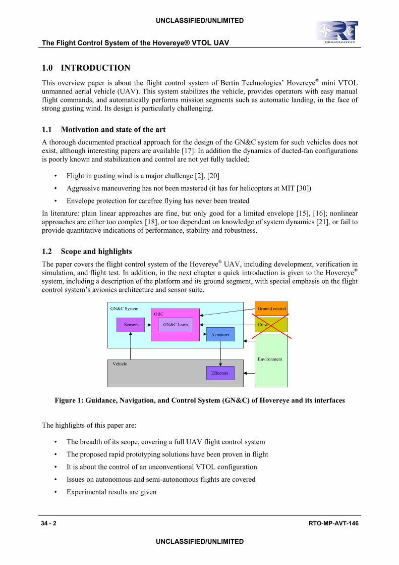
The paper covers the flight control system of the Hovereye® UAV, including development, verification in
simulation, and flight test. In addition, in the next chapter a quick introduction is given to the Hovereye®
system, including a description of the platform and its ground segment, with special emphasis on the flight
control system’s avionics architecture and sensor suite.
OBC
GN&C LawsSensors
Actuators
Effectors
Vehicle
GN&C System
Environment
Ground control
Crew
OBC
GN&C LawsSensors
Actuators
Effectors
Vehicle
GN&C System
Environment
Ground control
Crew
Figure 1: Guidance, Navigation, and Control System (GN&C) of Hovereye and its interfaces
The highlights of this paper are:
• The breadth of its scope, covering a full UAV flight control system
• The proposed rapid prototyping solutions have been proven in flight
• It is about the control of an unconventional VTOL configuration
• Issues on autonomous and semi-autonomous flights are covered
• Experimental results are given
The Flight Control System of the Hovereye® VTOL UAV
34 - 2 RTO-MP-AVT-146
UNCLASSIFIED/UNLIMITED
UNCLASSIFIED/UNLIMITED
2.0 THE HOVEREYE® VEHICLE
The Hovereye® demonstrator is VTOL UAV, which has been developed to military specifications for
very-short range combat intelligence. It is therefore a man-portable platform designed to operate in
complex, confined, obstacle-dense environments, with an electro-optic day or night camera payload.
Autonomous mini VTOL UAV have been studied and demonstrated, but no operational vehicles exist
today, although well funded US programs are helping some demonstrators to reach production, such as
within the DARPA Organic air vehicle (OAV) and OAVII programs. There is no equivalent program in
Europe with a comparable level of funding.
Bertin designed the Hovereye® on its funds and under a contract from DGA, the French Defence Research
and Development Agency, building on its previous know-how gained with the Flying Ball prototype.
Hovereye® is a ducted-fan configuration, which is advantageous for many reasons, including compact size
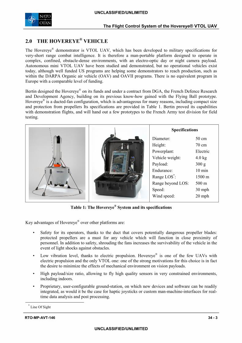
and protection from propellers Its specifications are provided in Table 1. Bertin proved its capabilities
with demonstration flights, and will hand out a few prototypes to the French Army test division for field
testing.
Specifications
Diameter: 50 cm
Height: 70 cm
Powerplant: Electric
Vehicle weight: 4.0 kg
Payload: 300 g
Endurance: 10 min
Range LOS*: 1500 m
Range beyond LOS: 500 m
Speed: 30 mph
Wind speed: 20 mph
Table 1: The Hovereye® System and its specifications
Key advantages of Hovereye® over other platforms are:
• Safety for its operators, thanks to the duct that covers potentially dangerous propeller blades:
protected propellers are a must for any vehicle which will function in close proximity of
personnel. In addition to safety, shrouding the fans increases the survivability of the vehicle in the
event of light shocks against obstacles.
• Low vibration level, thanks to electric propulsion. Hovereye® is one of the few UAVs with
electric propulsion and the only VTOL one: one of the strong motivations for this choice is in fact
the desire to minimize the effects of mechanical environment on vision payloads.
• High payload/size ratio, allowing to fly high quality sensors in very constrained environments,
including indoors.
• Proprietary, user-configurable ground-station, on which new devices and software can be readily
integrated, as would it be the case for haptic joysticks or custom man-machine-interfaces for real-
time data analysis and post processing.
* Line Of Sight
The Flight Control System of the Hovereye® VTOL UAV
RTO-MP-AVT-146 34 - 3
UNCLASSIFIED/UNLIMITED
UNCLASSIFIED/UNLIMITED
However, there are a number of design challenges to achieve such a vehicle, such as aerodynamics and
propulsion, weight and volume reduction, and flight control complexity.
2.1 Shape and aerodynamics
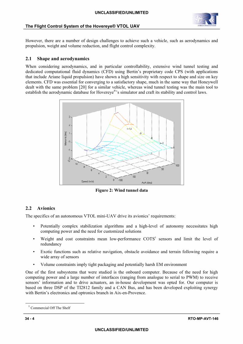
When considering aerodynamics, and in particular controllability, extensive wind tunnel testing and
dedicated computational fluid dynamics (CFD) using Bertin’s proprietary code CPS (with applications
that include Ariane liquid propulsion) have shown a high sensitivity with respect to shape and size on key
elements. CFD was essential for converging to a satisfactory shape, much in the same way that Honeywell
dealt with the same problem [20] for a similar vehicle, whereas wind tunnel testing was the main tool to
establish the aerodynamic database for Hovereye®’s simulator and craft its stability and control laws.
Figure 2: Wind tunnel data
2.2 Avionics
The specifics of an autonomous VTOL mini-UAV drive its avionics’ requirements:
• Potentially complex stabilization algorithms and a high-level of autonomy necessitates high
computing power and the need for customized solutions
• Weight and cost constraints mean low-performance COTS† sensors and limit the level of
redundancy
• Exotic functions such as relative navigation, obstacle avoidance and terrain following require a
wide array of sensors
• Volume constraints imply tight packaging and potentially harsh EM environment
One of the first subsystems that were studied is the onboard computer. Because of the need for high
computing power and a large number of interfaces (ranging from analogue to serial to PWM) to receive
sensors’ information and to drive actuators, an in-house development was opted for. Our computer is
based on three DSP of the TI2812 family and a CAN Bus, and has been developed exploiting synergy
with Bertin’s electronics and optronics branch in Aix-en-Provence.
† Commercial Off The Shelf
The Flight Control System of the Hovereye® VTOL UAV
34 - 4 RTO-MP-AVT-146
UNCLASSIFIED/UNLIMITED
UNCLASSIFIED/UNLIMITED
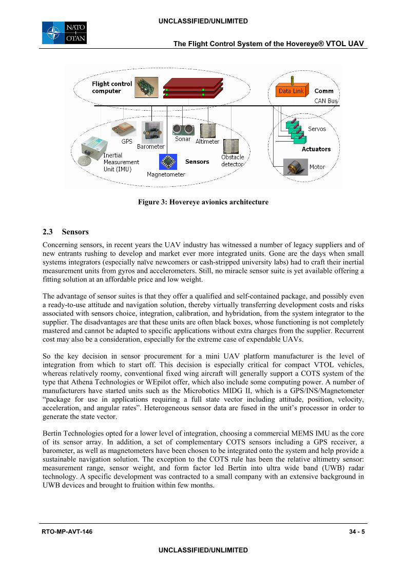
Figure 3: Hovereye avionics architecture
2.3 Sensors
Concerning sensors, in recent years the UAV industry has witnessed a number of legacy suppliers and of
new entrants rushing to develop and market ever more integrated units. Gone are the days when small
systems integrators (especially naïve newcomers or cash-stripped university labs) had to craft their inertial
measurement units from gyros and accelerometers. Still, no miracle sensor suite is yet available offering a
fitting solution at an affordable price and low weight.
The advantage of sensor suites is that they offer a qualified and self-contained package, and possibly even
a ready-to-use attitude and navigation solution, thereby virtually transferring development costs and risks
associated with sensors choice, integration, calibration, and hybridation, from the system integrator to the
supplier. The disadvantages are that these units are often black boxes, whose functioning is not completely
mastered and cannot be adapted to specific applications without extra charges from the supplier. Recurrent
cost may also be a consideration, especially for the extreme case of expendable UAVs.
So the key decision in sensor procurement for a mini UAV platform manufacturer is the level of
integration from which to start off. This decision is especially critical for compact VTOL vehicles,
whereas relatively roomy, conventional fixed wing aircraft will generally support a COTS system of the
type that Athena Technologies or WEpilot offer, which also include some computing power. A number of
manufacturers have started units such as the Microbotics MIDG II, which is a GPS/INS/Magnetometer
“package for use in applications requiring a full state vector including attitude, position, velocity,
acceleration, and angular rates”. Heterogeneous sensor data are fused in the unit’s processor in order to
generate the state vector.
Bertin Technologies opted for a lower level of integration, choosing a commercial MEMS IMU as the core
of its sensor array. In addition, a set of complementary COTS sensors including a GPS receiver, a
barometer, as well as magnetometers have been chosen to be integrated onto the system and help provide a
sustainable navigation solution. The exception to the COTS rule has been the relative altimetry sensor:
measurement range, sensor weight, and form factor led Bertin into ultra wide band (UWB) radar
technology. A specific development was contracted to a small company with an extensive background in
UWB devices and brought to fruition within few months.
The Flight Control System of the Hovereye® VTOL UAV
RTO-MP-AVT-146 34 - 5
UNCLASSIFIED/UNLIMITED
UNCLASSIFIED/UNLIMITED
3.0 FCS ARCHITECTURE AND DEVELOPMENT
This chapter is a summary of the main issues from a system standpoint. It includes a description of how
the control laws are structured, and of the rational behind the chosen architecture. Also insight is provided
into the special development logic that addresses the need to quickly get an UAV prototype to flight and
autonomy by exploiting modern technologies.
3.1 Control laws architecture
A functional point of view is the key to the understanding of the system. In order to reduce development
risk, a “vertical” decomposition is made, resulting in a hierarchical structure where higher layers are built
on lower feedback loops. The type and heterogeneity of sensors contribute to the choice of decoupling the
system into parallel channels, a “horizontal” decomposition, which contributes to the modularity of the
system, a requirement established to ensure growth potential.
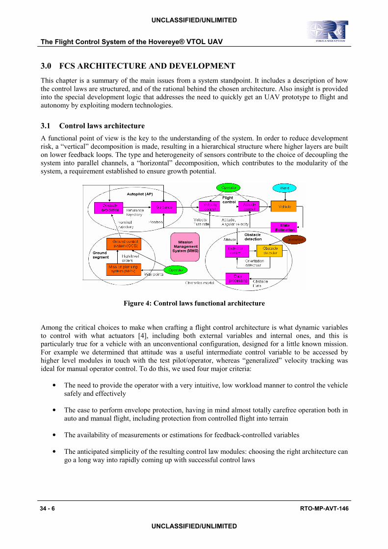
Figure 4: Control laws functional architecture
Among the critical choices to make when crafting a flight control architecture is what dynamic variables
to control with what actuators [4], including both external variables and internal ones, and this is
particularly true for a vehicle with an unconventional configuration, designed for a little known mission.
For example we determined that attitude was a useful intermediate control variable to be accessed by
higher level modules in touch with the test pilot/operator, whereas “generalized” velocity tracking was
ideal for manual operator control. To do this, we used four major criteria:
• The need to provide the operator with a very intuitive, low workload manner to control the vehicle
safely and effectively
• The ease to perform envelope protection, having in mind almost totally carefree operation both in
auto and manual flight, including protection from controlled flight into terrain
• The availability of measurements or estimations for feedback-controlled variables
• The anticipated simplicity of the resulting control law modules: choosing the right architecture can
go a long way into rapidly coming up with successful control laws
The Flight Control System of the Hovereye® VTOL UAV
34 - 6 RTO-MP-AVT-146
UNCLASSIFIED/UNLIMITED
UNCLASSIFIED/UNLIMITED
3.2 Development logic
A classical FCS development logic [3],[5] has been modified to take into account characteristics of a small
research and development prototype for which testing is relatively easier than obtaining very accurate
models for high-fidelity simulation, resources are limited, and schedule constraints are severe [7]. Another
major factor has been the availability of new technologies [8] such as model-based design and automatic
real-time code generation, for example those provided by the Mathworks.
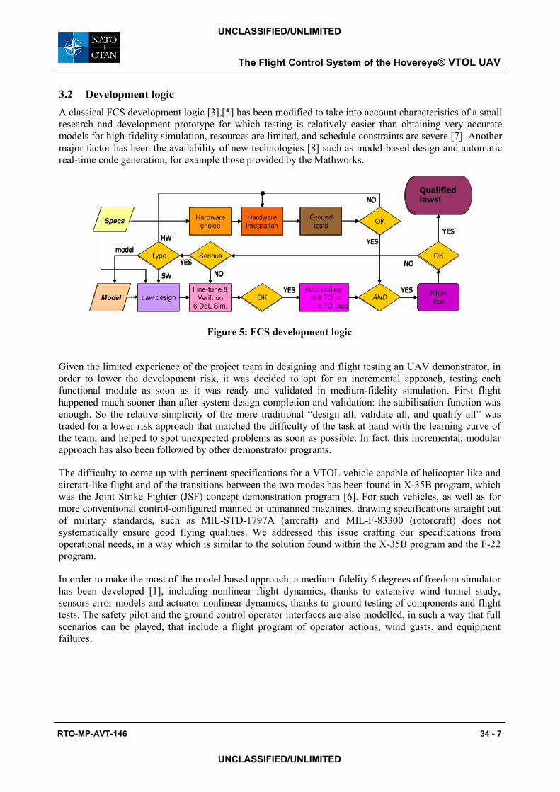
Figure 5: FCS development logic
Given the limited experience of the project team in designing and flight testing an UAV demonstrator, in
order to lower the development risk, it was decided to opt for an incremental approach, testing each
functional module as soon as it was ready and validated in medium-fidelity simulation. First flight
happened much sooner than after system design completion and validation: the stabilisation function was
enough. So the relative simplicity of the more traditional “design all, validate all, and qualify all” was
traded for a lower risk approach that matched the difficulty of the task at hand with the learning curve of
the team, and helped to spot unexpected problems as soon as possible. In fact, this incremental, modular
approach has also been followed by other demonstrator programs.
The difficulty to come up with pertinent specifications for a VTOL vehicle capable of helicopter-like and
aircraft-like flight and of the transitions between the two modes has been found in X-35B program, which
was the Joint Strike Fighter (JSF) concept demonstration program [6]. For such vehicles, as well as for
more conventional control-configured manned or unmanned machines, drawing specifications straight out
of military standards, such as MIL-STD-1797A (aircraft) and MIL-F-83300 (rotorcraft) does not
systematically ensure good flying qualities. We addressed this issue crafting our specifications from
operational needs, in a way which is similar to the solution found within the X-35B program and the F-22
program.
In order to make the most of the model-based approach, a medium-fidelity 6 degrees of freedom simulator
has been developed [1], including nonlinear flight dynamics, thanks to extensive wind tunnel study,
sensors error models and actuator nonlinear dynamics, thanks to ground testing of components and flight
tests. The safety pilot and the ground control operator interfaces are also modelled, in such a way that full
scenarios can be played, that include a flight program of operator actions, wind gusts, and equipment
failures.
The Flight Control System of the Hovereye® VTOL UAV
RTO-MP-AVT-146 34 - 7
UNCLASSIFIED/UNLIMITED
UNCLASSIFIED/UNLIMITED
Fine-tune &
Verif. on
6 DdL Sim.
Law design OKAuto-coding:
.mdl TO .c
.c TO .exe
ANDYES YES
Hardware
choice
Hardware
integration
Ground
testsSpecs
ModelFlight
test
OK
YES
NO
Serious
NO
OK
YES
NO
Qualifiedlaws!
TypeYES
HW
SW
model
Fine-tune &
Verif. on
6 DdL Sim.
Law design OKAuto-coding:
.mdl TO .c
.c TO .exe
ANDYES YES
Hardware
choice
Hardware
integration
Ground
testsSpecsSpecs
ModelModelFlight
test
OK
YES
NO
Serious
NO
OK
YES
NO
Qualifiedlaws!
TypeYES
HW
SW
model
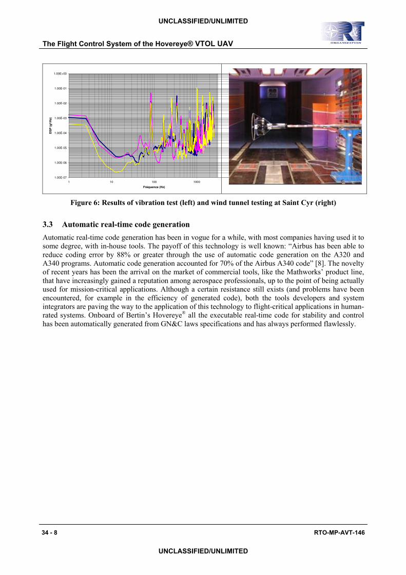
Figure 6: Results of vibration test (left) and wind tunnel testing at Saint Cyr (right)
3.3 Automatic real-time code generation
Automatic real-time code generation has been in vogue for a while, with most companies having used it to
some degree, with in-house tools. The payoff of this technology is well known: “Airbus has been able to
reduce coding error by 88% or greater through the use of automatic code generation on the A320 and
A340 programs. Automatic code generation accounted for 70% of the Airbus A340 code” [8]. The novelty
of recent years has been the arrival on the market of commercial tools, like the Mathworks’ product line,
that have increasingly gained a reputation among aerospace professionals, up to the point of being actually
used for mission-critical applications. Although a certain resistance still exists (and problems have been
encountered, for example in the efficiency of generated code), both the tools developers and system
integrators are paving the way to the application of this technology to flight-critical applications in human-
rated systems. Onboard of Bertin’s Hovereye® all the executable real-time code for stability and control
has been automatically generated from GN&C laws specifications and has always performed flawlessly.
1.00E-07
1.00E-06
1.00E-05
1.00E-04
1.00E-03
1.00E-02
1.00E-01
1.00E+00
1 10 100 1000
Fréquence (Hz)
DS
P (
g²/
Hz)
The Flight Control System of the Hovereye® VTOL UAV
34 - 8 RTO-MP-AVT-146
UNCLASSIFIED/UNLIMITED
UNCLASSIFIED/UNLIMITED
4.0 STABILITY AND CONTROL AUGMENTATION
A stable and manoeuvrable vehicle is the foundation on which all higher-level functions, such as guidance
are built: without it, they are useless. Moreover, this unconventional configuration also needs a proper
pilot interface, in order to be test-flown by a model helicopter pilot.
4.1 Hovereye®’s control challenges
Hovereye®’s is a particularly challenging plant to stabilize and control, for a number of reasons:
• It is an unstable machine, whose dynamics can be particularly rapid (see the figure below): it
cannot be flown without a properly sized artificial stabilization system [12];
• Aerodynamic moments are significant and very sensitive to flight conditions, their dependence
from relative wind being nonlinear and complex to model;
• Relative wind is hard to measure or estimate
• Control surface effectiveness depends on flight conditions in addition to thrust; this can also
produce undesirable control couplings
• Hovereye routinely performs big rotations and flies at high pitch and roll: this implies nonlinear
kinematic coupling
• Because of aggressive 3D manoeuvring, nonlinear inertial coupling cannot be neglected
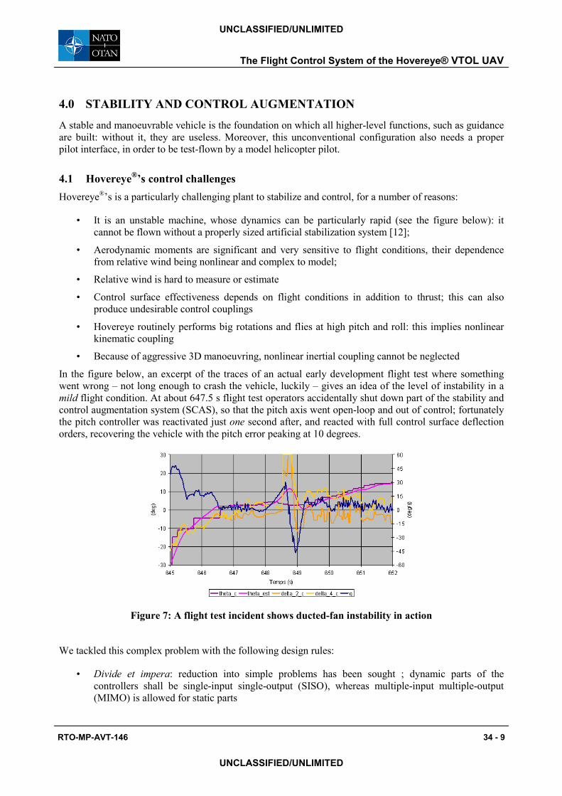
In the figure below, an excerpt of the traces of an actual early development flight test where something
went wrong – not long enough to crash the vehicle, luckily – gives an idea of the level of instability in a
mild flight condition. At about 647.5 s flight test operators accidentally shut down part of the stability and
control augmentation system (SCAS), so that the pitch axis went open-loop and out of control; fortunately
the pitch controller was reactivated just one second after, and reacted with full control surface deflection
orders, recovering the vehicle with the pitch error peaking at 10 degrees.
Figure 7: A flight test incident shows ducted-fan instability in action
We tackled this complex problem with the following design rules:
• Divide et impera: reduction into simple problems has been sought ; dynamic parts of the
controllers shall be single-input single-output (SISO), whereas multiple-input multiple-output
(MIMO) is allowed for static parts
The Flight Control System of the Hovereye® VTOL UAV
RTO-MP-AVT-146 34 - 9
UNCLASSIFIED/UNLIMITED
UNCLASSIFIED/UNLIMITED
• Each part of the controller must have a clear physical interpretation
• Reliance on internal modelling and non-inertial measurement must be minimal
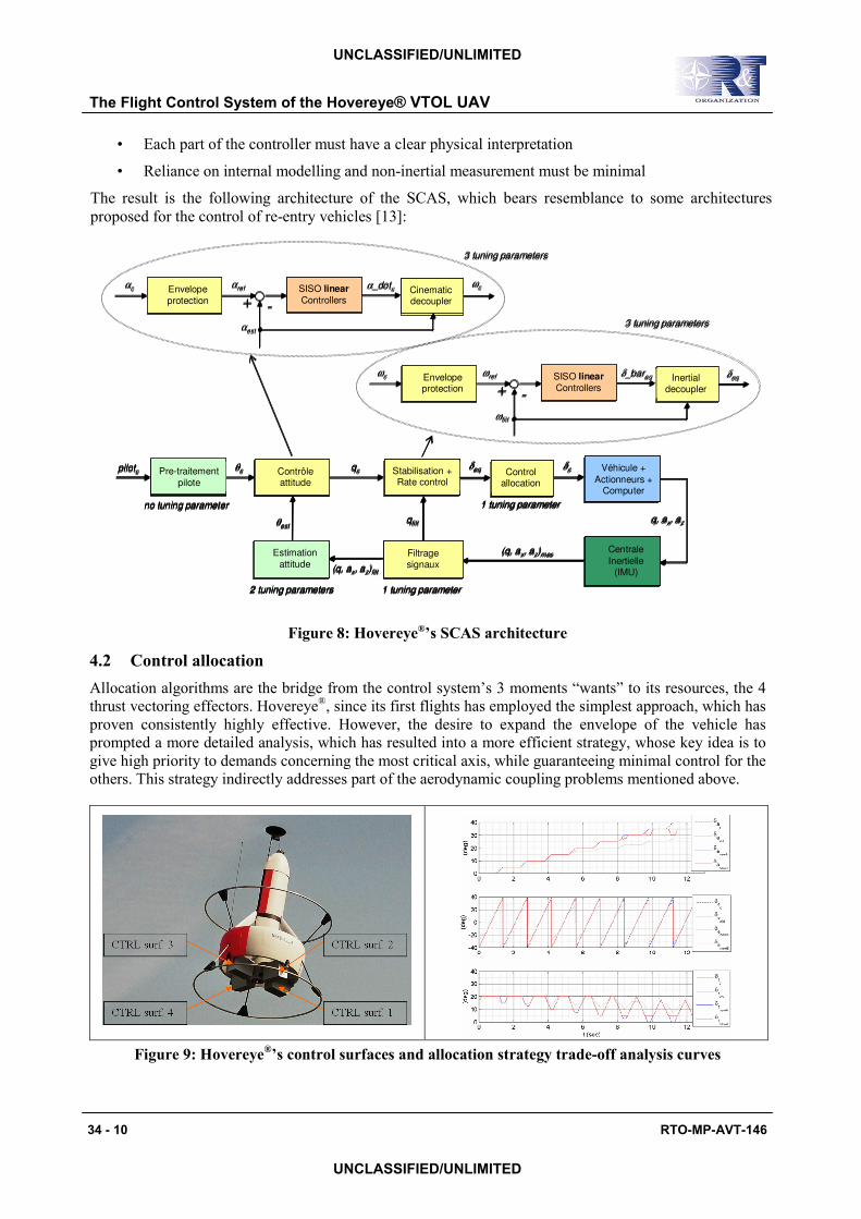
The result is the following architecture of the SCAS, which bears resemblance to some architectures
proposed for the control of re-entry vehicles [13]:
Figure 8: Hovereye®’s SCAS architecture
4.2 Control allocation
Allocation algorithms are the bridge from the control system’s 3 moments “wants” to its resources, the 4
thrust vectoring effectors. Hovereye®, since its first flights has employed the simplest approach, which has
proven consistently highly effective. However, the desire to expand the envelope of the vehicle has
prompted a more detailed analysis, which has resulted into a more efficient strategy, whose key idea is to
give high priority to demands concerning the most critical axis, while guaranteeing minimal control for the
others. This strategy indirectly addresses part of the aerodynamic coupling problems mentioned above.
Figure 9: Hovereye®’s control surfaces and allocation strategy trade-off analysis curves
The Flight Control System of the Hovereye® VTOL UAV
34 - 10 RTO-MP-AVT-146
UNCLASSIFIED/UNLIMITED
UNCLASSIFIED/UNLIMITED
Envelope
protection-+
SISO linearControllers
α_dotc Cinematicdecoupler
ωc
αest
αrefαc
Envelopeprotection
-+
δ_bareq Inertialdecoupler
ωfilt
ωrefωc SISO linearControllers
δeq
3 tuning parameters
3 tuning parameters
Contrôleattitude
Véhicule +
Actionneurs +Computer
Stabilisation +Rate control
Centrale
Inertielle(IMU)
(q, ax, az)mes
δeqθc qc
Estimation
attitudeFiltragesignaux
qfilt
(q, ax, az)filt
Controlallocation
δc
q, ax, azθest
Pre-traitement
pilote
pilotc
2 tuning parameters 1 tuning parameter
1 tuning parameterno tuning parameter
Envelope
protection
Envelope
protection-+
SISO linearControllers
SISO linearControllers
α_dotc CinematicdecouplerCinematicdecoupler
ωc
αest
αrefαc
EnvelopeprotectionEnvelopeprotection
-+
δ_bareq Inertialdecoupler
Inertialdecoupler
ωfilt
ωrefωc SISO linearControllers
SISO linearControllers
δeq
3 tuning parameters
3 tuning parameters
Contrôleattitude
Véhicule +
Actionneurs +Computer
Stabilisation +Rate control
Centrale
Inertielle(IMU)
(q, ax, az)mes
δeqθc qc
Estimation
attitudeFiltragesignaux
qfilt
(q, ax, az)filt
Controlallocation
δc
q, ax, azθest
Pre-traitement
pilote
pilotc
2 tuning parameters 1 tuning parameter
1 tuning parameterno tuning parameter
ContrôleattitudeContrôleattitude
Véhicule +
Actionneurs +Computer
Véhicule +
Actionneurs +Computer
Stabilisation +Rate control
Stabilisation +Rate control
Centrale
Inertielle(IMU)
Centrale
Inertielle(IMU)
(q, ax, az)mes
δeqθc qc
Estimation
attitude
Estimation
attitudeFiltragesignauxFiltragesignaux
qfilt
(q, ax, az)filt
ControlallocationControl
allocation
δc
q, ax, azθest
Pre-traitement
pilote
Pre-traitement
pilote
pilotc
2 tuning parameters 1 tuning parameter
1 tuning parameterno tuning parameter
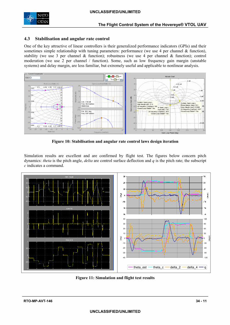
4.3 Stabilisation and angular rate control
One of the key attractive of linear controllers is their generalized performance indicators (GPIs) and their
sometimes simple relationship with tuning parameters: performance (we use 4 per channel & function),
stability (we use 3 per channel & function); robustness (we use 4 per channel & function); control
moderation (we use 2 per channel / function). Some, such as low frequency gain margin (unstable
systems) and delay margin, are less familiar, but extremely useful and applicable to nonlinear analysis.
Figure 10: Stabilisation and angular rate control laws design iteration
Simulation results are excellent and are confirmed by flight test. The figures below concern pitch
dynamics: theta is the pitch angle, delta are control surface deflection and q is the pitch rate; the subscript
c indicates a command.
Figure 11: Simulation and flight test results
-40
-30
-20
-10
0
10
20
30
40
(de
g)
-120
-90
-60
-30
0
30
60
90
120
(de
g/s
)
theta_est theta_c delta_2 delta_4 q
The Flight Control System of the Hovereye® VTOL UAV
RTO-MP-AVT-146 34 - 11
UNCLASSIFIED/UNLIMITED
UNCLASSIFIED/UNLIMITED
5.0 NAVIGATION, GUIDANCE, AND HIGH LEVEL FUNCTIONS
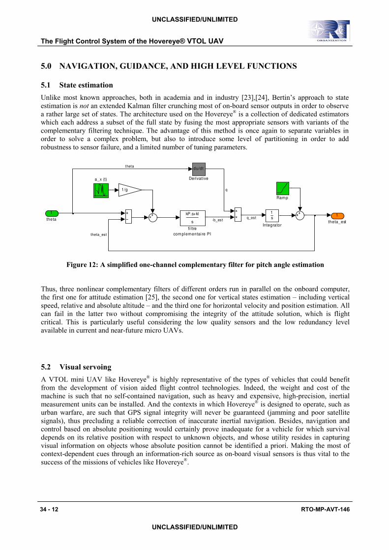
5.1 State estimation
Unlike most known approaches, both in academia and in industry [23],[24], Bertin’s approach to state
estimation is not an extended Kalman filter crunching most of on-board sensor outputs in order to observe
a rather large set of states. The architecture used on the Hovereye® is a collection of dedicated estimators
which each address a subset of the full state by fusing the most appropriate sensors with variants of the
complementary filtering technique. The advantage of this method is once again to separate variables in
order to solve a complex problem, but also to introduce some level of partitioning in order to add
robustness to sensor failure, and a limited number of tuning parameters.
1
theta_est
kP.s+kI
s
fi l tre
com plementai re PI
a_x (t)
Ramp
1
s
Integrator
1/g
du/dt
Derivative
1
theta
theta_est
q_est-b_est
q
theta
Figure 12: A simplified one-channel complementary filter for pitch angle estimation
Thus, three nonlinear complementary filters of different orders run in parallel on the onboard computer,
the first one for attitude estimation [25], the second one for vertical states estimation – including vertical
speed, relative and absolute altitude – and the third one for horizontal velocity and position estimation. All
can fail in the latter two without compromising the integrity of the attitude solution, which is flight
critical. This is particularly useful considering the low quality sensors and the low redundancy level
available in current and near-future micro UAVs.
5.2 Visual servoing
A VTOL mini UAV like Hovereye® is highly representative of the types of vehicles that could benefit
from the development of vision aided flight control technologies. Indeed, the weight and cost of the
machine is such that no self-contained navigation, such as heavy and expensive, high-precision, inertial
measurement units can be installed. And the contexts in which Hovereye® is designed to operate, such as
urban warfare, are such that GPS signal integrity will never be guaranteed (jamming and poor satellite
signals), thus precluding a reliable correction of inaccurate inertial navigation. Besides, navigation and
control based on absolute positioning would certainly prove inadequate for a vehicle for which survival
depends on its relative position with respect to unknown objects, and whose utility resides in capturing
visual information on objects whose absolute position cannot be identified a priori. Making the most of
context-dependent cues through an information-rich source as on-board visual sensors is thus vital to the
success of the missions of vehicles like Hovereye®.
The Flight Control System of the Hovereye® VTOL UAV
34 - 12 RTO-MP-AVT-146
UNCLASSIFIED/UNLIMITED
UNCLASSIFIED/UNLIMITED
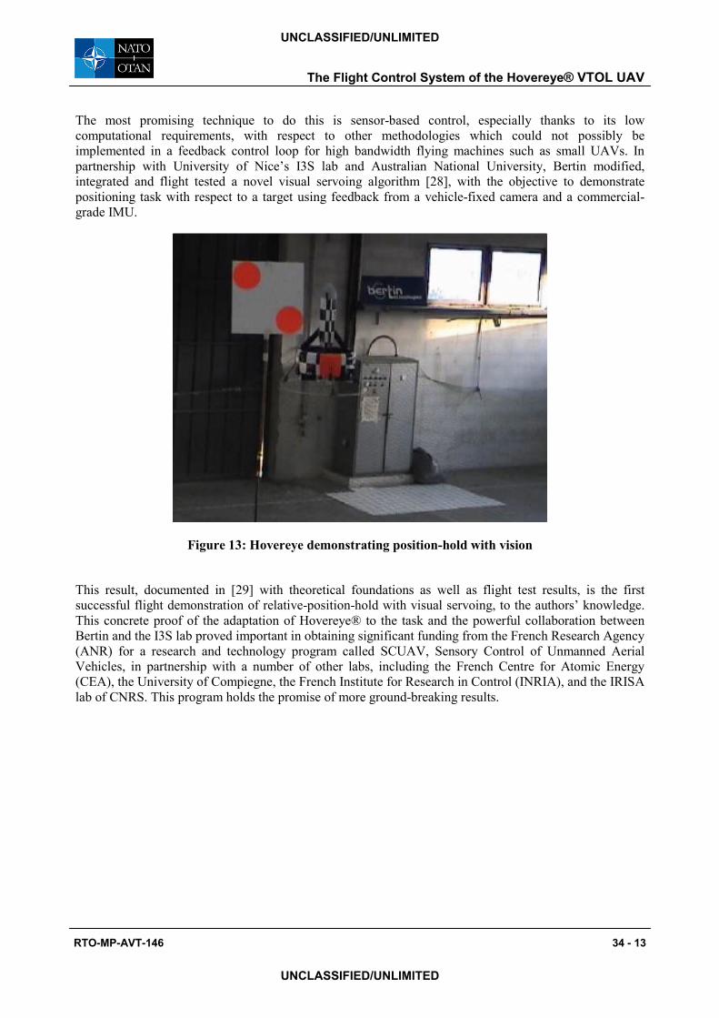
The most promising technique to do this is sensor-based control, especially thanks to its low
computational requirements, with respect to other methodologies which could not possibly be
implemented in a feedback control loop for high bandwidth flying machines such as small UAVs. In
partnership with University of Nice’s I3S lab and Australian National University, Bertin modified,
integrated and flight tested a novel visual servoing algorithm [28], with the objective to demonstrate
positioning task with respect to a target using feedback from a vehicle-fixed camera and a commercial-
grade IMU.
Figure 13: Hovereye demonstrating position-hold with vision
This result, documented in [29] with theoretical foundations as well as flight test results, is the first
successful flight demonstration of relative-position-hold with visual servoing, to the authors’ knowledge.
This concrete proof of the adaptation of Hovereye® to the task and the powerful collaboration between
Bertin and the I3S lab proved important in obtaining significant funding from the French Research Agency
(ANR) for a research and technology program called SCUAV, Sensory Control of Unmanned Aerial
Vehicles, in partnership with a number of other labs, including the French Centre for Atomic Energy
(CEA), the University of Compiegne, the French Institute for Research in Control (INRIA), and the IRISA
lab of CNRS. This program holds the promise of more ground-breaking results.
The Flight Control System of the Hovereye® VTOL UAV
RTO-MP-AVT-146 34 - 13
UNCLASSIFIED/UNLIMITED
UNCLASSIFIED/UNLIMITED
6.0 BIBLIOGRAPHY
6.1 Modelling and Simulation
[1] M. V. Cook, “Flight Dynamics Principles“, 1st Ed., Arnold, London, UK, 1997
[2] M. M. Lazareff, “L’Hélice Carénée – Performances actuelles et possibilités futures”, Colloque
d’aérodynamique appliquée, Ecole National Supérieure de l’Aéronautique – Paris, November 1964
6.2 Control system architecture and development
[3] R. W. Pratt, “Flight Control Systems – Practical Issues in Design and Implementation”, IEE &
AIAA, 2000
[4] M. B. Tischler (ed.), “Advances in Aircraft Flight Control”, Taylor & Francis, London, 1996
[5] P. A. Vidal, “NH-90 Helicopter Fly-By-Wire Flight Control System”, 53rd American Helicopter
Society Annual Forum, Virginia Beach, VA, April 1997
[6] G. P. Walker, D. A. Allen, “X-35B STOVL Flight Control Law Design and Flying Qualities”, AIAA
2002-6018, 2002 Biennial International Powered Lift Conference and Exhibit, 5-7 November 2002,
Williamsburg, Virginia
[7] J. D. Colbourne, M. B. Tischler, K Rodgers, “Flight Control Design for an Unmanned Rotorcraft
Program with a Rapid Development Schedule”, 57th American Helicopter Society Annual Forum,
Washington DC, May 2001
[8] Jose K. Menendez, “Building Software Factories in the Aerospace Industry”, M.S. Thesis,
Massachusetts Institute of Technology, February 1997
6.3 Stability and control
[9] P. Bolzern, R. Scattolini, N. Schiavoni, “Fondamenti di Controlli Automatici”, McGraw-Hill
[10] NATO RTO, “Flight Control Design – Best Practices”, RTO-TR-029, December 2003
[11] J. A. Franklin, “Dynamics, Control, and Flying Qualities of V/STOL Aircraft”, 1st Ed., AIAA
Education Series, Reston, VA, 2002
[12] G. Stein, ”Respect the Unstable”, IEEE Control Systems Magazine, pages 12-25, Aug. 2003
[13] D. Ito, J. Georgie, J. Valasek, and D. T. Ward, “Reentry Vehicle Flight Controls Design Guidelines:
Dynamic Inversion”, NASA/TP-2002–210771, March 2002
[14] Pollini, L., Innocenti, M., Greco, L., "Stability Issues in Dual time Scale Systems", Automatica, num.
2, vol. 39, p. 273, 2003
6.4 Stabilization and control of ducted fans
[15] S. Ando, “A simple Theory on Hovering Stability of One-Ducted-Fan VTOL”, Trans. Japan Soc.
Aero. Space Sci., Vol. 29, No. 86, pages 242-250, Feb. 1987.
The Flight Control System of the Hovereye® VTOL UAV
34 - 14 RTO-MP-AVT-146
UNCLASSIFIED/UNLIMITED
UNCLASSIFIED/UNLIMITED
[16] J. E. White, J. R. Phelan, “Stability Augmentation for a Free Flying Ducted Fan”, AIAA 87-2453
[17] L. Lipera, J. D. Colbourne, M. Tischler, M. Hossein Mansur, M. C. Rotkowitz, and P. Patangui,
“The Micro Craft iSTAR Micro Air Vehicle: Control System Design and Testing”, 57th American
Helicopter Society Annual Forum, Washington DC, May 2001
[18] R. Franz, M. Milam, and J. Hauser, “Applied Receding Control of the Caltech Ducted Fan”,
Proceedings of the American Control Conference, Anchorage, USA, May 2002, pp. 3735–3740.
[19] G. Avanzini, S. D’Angelo, and G. de Matteis, “Performance and Stability of Ducted-Fan
Uninhabited Aerial Vehicle Model”, Journal of Aircraft, Vol. 40, No. 1, 86-93, Jan.-Feb. 2003.
[20] J. Fleming, T. Jones, P. Gelhausen, and D. Enns, “Improving Control System Effectiveness for
Ducted Fan VTOL UAVs Operating in Crosswinds”, 2nd “Unmmanned Unlimited” Systems,
Technologies, and Operations, San Diego, California, AIAA-2003-6514, September 2003. .
[21] C. M. Spaulding, M. H. Mansur, M. B. Tischler, R. A. Hess, and J. A. Franklin, “Nonlinear inversion
Control for a Ducted Fan UAV”, AIAA 2005-6231
[22] J. M. Pflimlin, T. Hamel, P. Soueres, and R. Mahony, “A Hierarchical Control Strategy for the
Autonomous Navigation of a Ducted Fan UAV”, IEEE International Conference on Robotics and
Automation (ICRA'06)
6.5 State estimation
[23] RTO Educational Notes, “Advances in Navigation Sensors and Integration Technology”, EN-SET-064, February 2004
[24] D. Titterton et J. Weston, “Strapdown Inertial Navigation Technology”, 2nd Edition, Institute of
Electrical Engineers and the American Institute of Aeronautics and Astronautics, 2004
[25] J. M. Pflimlin, T. Hamel, P. Soueres, N. Metni, “Nonlinear attitude and gyroscope’s bias estimation
for a VTOL UAV”, 16th IFAC World Congress, Prague, Czech republic, 2005
6.6 Guidance
[26] M. Innocenti, L. Pollini, “Sistemi di Guida e Navigazione”, Appunti delle lezioni A.A. 2003-2004,
Pisa, January 2004
[27] M. Krstic, P.V. Kokotovic and I. Kanellakopoulos, “Nonlinear and adaptive control design”, John
Wiley & Sons, Inc. New York, 1995
[28] T. Hamel, R. Mahony, “Visual servoing of an under-actuated dynamic rigid-body system: An image
based approach”, IEEE Transactions on Robotics and Automation, pages 187-198, April 2002
[29] F. Le Bras, R. Mahony, T. Hamel and P. Binetti, “Adaptive filtering and image based visual servo
control of a ducted fan flying robot”, IEEE Conference on Decision and Control, CDC06, San Diego,
USA, December 2006
[30] E. Frazzoli, M.A. Dahleh, and E. Feron, “A Hybrid Control Architecture for Aggressive
Maneuvering of Autonomous Helicopters”, 1999 IEEE Conference on Decision and Control
The Flight Control System of the Hovereye® VTOL UAV
RTO-MP-AVT-146 34 - 15
UNCLASSIFIED/UNLIMITED
UNCLASSIFIED/UNLIMITED
The Flight Control System of the Hovereye® VTOL UAV
34 - 16 RTO-MP-AVT-146
UNCLASSIFIED/UNLIMITED
UNCLASSIFIED/UNLIMITED