TA - TA2 THERMOSTAT D’AMBIANCE - Gallettiord.galletti.com/imagesdb/famiglie/pdf/fc66000648.pdf ·...
8
SPM SPM SPM SPM SPM TA - T A - T A - T A - T A - TA2 A2 A2 A2 A2 TERMOSTATI AMBIENTE TA - T A - T A - T A - T A - TA2 A2 A2 A2 A2 ROOM THERMOSTAT TA - T A - T A - T A - T A - TA2 A2 A2 A2 A2 THERMOSTAT D’AMBIANCE TA - T A - T A - T A - T A - TA2 A2 A2 A2 A2 RAUMTHERMOSTAT TA - T A - T A - T A - T A - TA2 A2 A2 A2 A2 TERMOSTATO DE AMBIENTE TA - T A - T A - T A - T A - TA2 A2 A2 A2 A2 TERMOSTATOS AMBIENTES TA - T A - T A - T A - T A - TA2 A2 A2 A2 A2 OMGEVINGSTHERMOSTAAT TA - T A - T A - T A - T A - TA2 A2 A2 A2 A2
Transcript of TA - TA2 THERMOSTAT D’AMBIANCE - Gallettiord.galletti.com/imagesdb/famiglie/pdf/fc66000648.pdf ·...
SPMSPMSPMSPMSPM
���
�
��
�
�
�
�
�
TTTTTA - TA - TA - TA - TA - TA2 A2 A2 A2 A2 TERMOSTATI AMBIENTE
TTTTTA - TA - TA - TA - TA - TA2 A2 A2 A2 A2 ROOM THERMOSTAT
TTTTTA - TA - TA - TA - TA - TA2 A2 A2 A2 A2 THERMOSTAT D’AMBIANCE
TTTTTA - TA - TA - TA - TA - TA2 A2 A2 A2 A2 RAUMTHERMOSTAT
TTTTTA - TA - TA - TA - TA - TA2 A2 A2 A2 A2 TERMOSTATO DE AMBIENTE
TTTTTA - TA - TA - TA - TA - TA2 A2 A2 A2 A2 TERMOSTATOS AMBIENTES
TTTTTA - TA - TA - TA - TA - TA2 A2 A2 A2 A2 OMGEVINGSTHERMOSTAAT
TTTTTA - TA - TA - TA - TA - TA2 A2 A2 A2 A2
2FC66000648 - rev. 01
TA - TA2
È severamente vietata la riproduzione anche parziale di questo manuale / All copying, even partial, of this manual is strictly forbidden
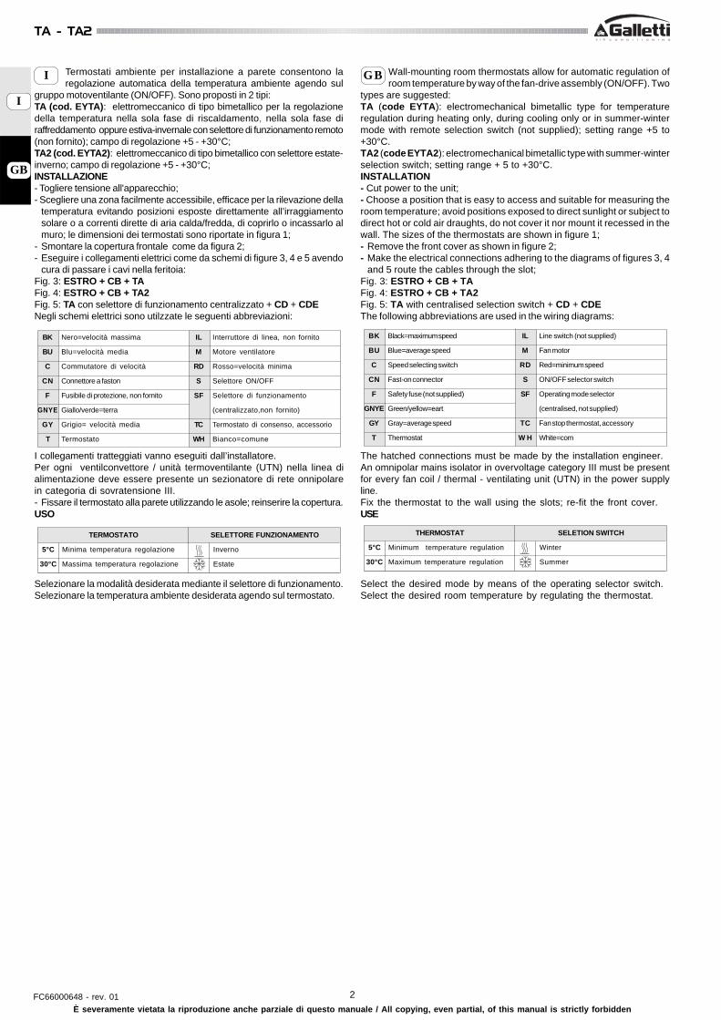
Termostati ambiente per installazione a parete consentono laregolazione automatica della temperatura ambiente agendo sul
gruppo motoventilante (ON/OFF). Sono proposti in 2 tipi:TA (cod. EYTA): elettromeccanico di tipo bimetallico per la regolazionedella temperatura nella sola fase di riscaldamento, nella sola fase diraffreddamento oppure estiva-invernale con selettore di funzionamento remoto(non fornito); campo di regolazione +5 - +30°C;TA2 (cod. EYTA2): elettromeccanico di tipo bimetallico con selettore estate-inverno; campo di regolazione +5 - +30°C;INSTALLAZIONE- Togliere tensione all'apparecchio;- Scegliere una zona facilmente accessibile, efficace per la rilevazione della
temperatura evitando posizioni esposte direttamente all’irraggiamentosolare o a correnti dirette di aria calda/fredda, di coprirlo o incassarlo almuro; le dimensioni dei termostati sono riportate in figura 1;
- Smontare la copertura frontale come da figura 2;- Eseguire i collegamenti elettrici come da schemi di figure 3, 4 e 5 avendo
cura di passare i cavi nella feritoia:Fig. 3: ESTRO + CB + TAFig. 4: ESTRO + CB + TA2Fig. 5: TA con selettore di funzionamento centralizzato + CD + CDENegli schemi elettrici sono utilzzate le seguenti abbreviazioni:
I collegamenti tratteggiati vanno eseguiti dall’installatore.Per ogni ventilconvettore / unità termoventilante (UTN) nella linea dialimentazione deve essere presente un sezionatore di rete onnipolarein categoria di sovratensione III.- Fissare il termostato alla parete utilizzando le asole; reinserire la copertura.USO
Selezionare la modalità desiderata mediante il selettore di funzionamento.Selezionare la temperatura ambiente desiderata agendo sul termostato.
GB
I
I GB
BK Nero=velocità massima
BU Blu=velocità media
C Commutatore di velocità
CN Connettore a faston
F Fusibile di protezione, non fornito
GNYE Giallo/verde=terra
GY Grigio= velocità media
T Termostato
IL Interruttore di linea, non fornito
M Motore ventilatore
RD Rosso=velocità minima
S Selettore ON/OFF
SF Selettore di funzionamento
(centralizzato,non fornito)
TC Termostato di consenso, accessorio
WH Bianco=comune
BK Black=maximum speed
BU Blue=average speed
C Speed selecting switch
CN Fast-on connector
F Safety fuse (not supplied)
GNYE Green/yellow=eart
GY Gray=average speed
T Thermostat
IL Line switch (not supplied)
M Fan motor
RD Red=minimum speed
S ON/OFF selector switch
SF Operating mode selector
(centralised, not supplied)
TC Fan stop thermostat, accessory
W H White=com
Wall-mounting room thermostats allow for automatic regulation ofroom temperature by way of the fan-drive assembly (ON/OFF). Two
types are suggested:TA (code EYTA): electromechanical bimetallic type for temperatureregulation during heating only, during cooling only or in summer-wintermode with remote selection switch (not supplied); setting range +5 to+30°C.TA2 (code EYTA2): electromechanical bimetallic type with summer-winterselection switch; setting range + 5 to +30°C.INSTALLATION- Cut power to the unit;- Choose a position that is easy to access and suitable for measuring theroom temperature; avoid positions exposed to direct sunlight or subject todirect hot or cold air draughts, do not cover it nor mount it recessed in thewall. The sizes of the thermostats are shown in figure 1;- Remove the front cover as shown in figure 2;- Make the electrical connections adhering to the diagrams of figures 3, 4
and 5 route the cables through the slot;Fig. 3: ESTRO + CB + TAFig. 4: ESTRO + CB + TA2Fig. 5: TA with centralised selection switch + CD + CDEThe following abbreviations are used in the wiring diagrams:
The hatched connections must be made by the installation engineer.An omnipolar mains isolator in overvoltage category III must be presentfor every fan coil / thermal - ventilating unit (UTN) in the power supplyline.Fix the thermostat to the wall using the slots; re-fit the front cover.USE
Select the desired mode by means of the operating selector switch.Select the desired room temperature by regulating the thermostat.
TERMOSTATO
5°C Minima temperatura regolazione
30°C Massima temperatura regolazione
SELETTORE FUNZIONAMENTO
Inverno
Estate
THERMOSTAT
5°C Minimum temperature regulation
30°C Maximum temperature regulation
SELETION SWITCH
Winter
Summer
3 FC66000648 - rev. 01
TA - TA2
È severamente vietata la riproduzione anche parziale di questo manuale / All copying, even partial, of this manual is strictly forbidden
Mit den Raumthermostaten für die Wandinstallation ist dieautomatische Regelung der Raumtemperatur durch Ein- oder
Ausschaltung des Ventilatorantriebsaggregats (ON/OFF) möglich. Es sindzwei Typen erhältlich:TA (Art.-Nr. EYTA): elektromechanischer bimetallischer Thermostat für dieTemperaturregelung nur im Heizbetrieb, nur im Kühlbetrieb oder im Sommer-/Winterbetrieb mit Fernwahlschalter (nicht mitgeliefert). Regelbereich von+5 bis +30°C;TA2 (Art.-Nr. EYTA2): elektromechanischer bimetallischer Thermostat mitWahlschalter Sommer-Winterbetrieb; Regelbereich von + 5 bis +30°C;INSTALLATION- Die Spannung vom Gerät abnehmen.- Einen leicht zugänglichen und für die Temperaturmessung geeigneten
Bereich wählen. Positionen, die direkt dem Sonnenlicht bzw. heißer oderkalter Zugluft ausgesetzt sind, sollten vermieden werden. Den Thermostatnicht abdecken oder unter Putz montieren. Die Abmessungen derThermostate werden in Abbildung 1 gezeigt.
- Die Frontabdeckung gemäß Abbildung 2 abnehmen.- Die elektrischen Anschlüsse gemäß den Schaltplänen der Abbildungen
3, 4 und 5 ausführen. Dabei ist darauf zu achten, daß die Kabel durch denSchlitz gezogen werden.
Abb. 3: ESTRO + CB + TAAbb. 4: ESTRO + CB + TA2Abb. 5: TA mit zentralisiertem Betriebswahlschalter + CD + CDEIn den elektrischen Schaltplänen werden folgende Abkürzungen verwendet:
Die gestrichelt abgebildeten Anschlüsse sind vom Installateurauszuführen.Für jeden Ventilatorkonvektor / Gebläseheizeinheiten UTN in derVersorgungslinie muss ein allpoliger Trennschalter inÜberspannungskategorie III zur Verfügung stehen.Den Thermostat mit den Langlöchern an der Wand befestigen. Dann dieFrontabdeckung wieder anbringen.GEBRAUCH
Die gewünschte Betriebsart mit dem Betriebswahlschalter anwählen.Die gewünschte Raumtemperatur auf dem Thermostat anwählen.
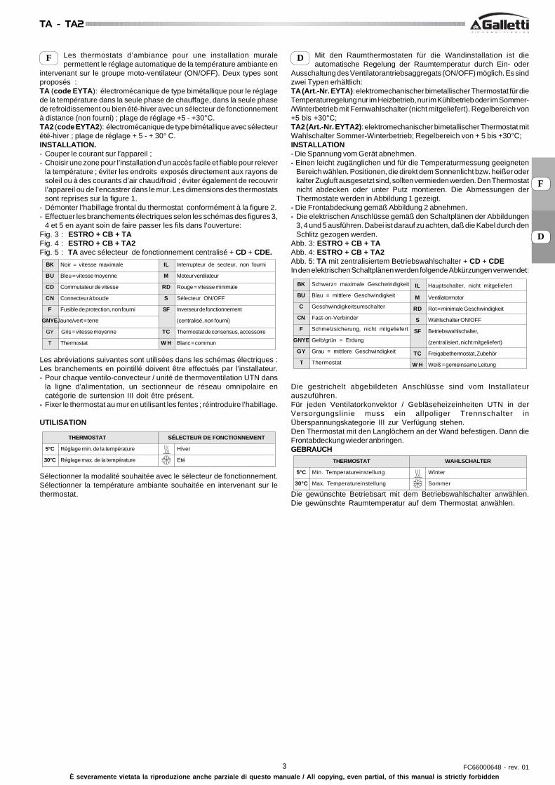
DLes thermostats d’ambiance pour une installation muralepermettent le réglage automatique de la température ambiante en
intervenant sur le groupe moto-ventilateur (ON/OFF). Deux types sontproposés :TA (code EYTA): électromécanique de type bimétallique pour le réglagede la température dans la seule phase de chauffage, dans la seule phasede refroidissement ou bien été-hiver avec un sélecteur de fonctionnementà distance (non fourni) ; plage de réglage +5 - +30°C.TA2 (code EYTA2): électromécanique de type bimétallique avec sélecteurété-hiver ; plage de réglage + 5 - + 30° C.INSTALLATION.- Couper le courant sur l’appareil ;- Choisir une zone pour l’installation d’un accès facile et fiable pour relever
la température ; éviter les endroits exposés directement aux rayons desoleil ou à des courants d’air chaud/froid ; éviter également de recouvrirl’appareil ou de l’encastrer dans le mur. Les dimensions des thermostatssont reprises sur la figure 1.
- Démonter l’habillage frontal du thermostat conformément à la figure 2.- Effectuer les branchements électriques selon les schémas des figures 3,
4 et 5 en ayant soin de faire passer les fils dans l’ouverture:Fig. 3 : ESTRO + CB + TAFig. 4 : ESTRO + CB + TA2Fig. 5 : TA avec sélecteur de fonctionnement centralisé + CD + CDE.
Les abréviations suivantes sont utilisées dans les schémas électriques :Les branchements en pointillé doivent être effectués par l’installateur.- Pour chaque ventilo-convecteur / unité de thermoventilation UTN dans
la ligne d'alimentation, un sectionneur de réseau omnipolaire encatégorie de surtension III doit être présent.
- Fixer le thermostat au mur en utilisant les fentes ; réintroduire l’habillage.
UTILISATION
Sélectionner la modalité souhaitée avec le sélecteur de fonctionnement.Sélectionner la température ambiante souhaitée en intervenant sur lethermostat.
F
BK Noir = vitesse maximale
BU Bleu = vitesse moyenne
CD Commutateur de vitesse
CN Connecteur à boucle
F Fusible de protection, non fourni
GNYEJaune/vert = terre
GY Gris = vitesse moyenne
T Thermostat
IL Interrupteur de secteur, non fourni
M Moteur ventilateur
RD Rouge = vitesse minimale
S Sélecteur ON/OFF
SF Inverseur de fonctionnement
(centralisé, non fourni)
TC Thermostat de consensus, accessoire
W H Blanc = commun
BK Schwarz= maximale Geschwindigkeit
BU Blau = mittlere Geschwindigkeit
C Geschwindigkeitsumschalter
CN Fast-on-Verbinder
F Schmelzsicherung, nicht mitgeliefert
GNYE Gelb/grün = Erdung
GY Grau = mittlere Geschwindigkeit
T Thermostat
IL Hauptschalter, nicht mitgeliefert
M Ventilatormotor
RD Rot = minimale Geschwindigkeit
S Wahlschalter ON/OFF
SF Betriebswahlschalter,
(zentralisiert, nicht mitgeliefert)
TC Freigabethermostat, Zubehör
W H Weiß = gemeinsame Leitung
F
D
THERMOSTAT
5°C Réglage min. de la température
30°C Réglage max. de la température
SÉLECTEUR DE FONCTIONNEMENT
Hiver
Eté WAHLSCHALTER
Winter
Sommer
THERMOSTAT
5°C Min. Temperatureinstellung
30°C Max. Temperatureinstellung
4FC66000648 - rev. 01
TA - TA2
È severamente vietata la riproduzione anche parziale di questo manuale / All copying, even partial, of this manual is strictly forbidden
E PLos termostatos de ambiente de instalación mural a la vista,permiten regular la temperatura ambiente de modo automático
interviniendo en la unidad motoventiladora (ON/OFF). Se proponen dostipos diferentes:TA (cód. EYTA): electromecánico, de tipo bimetálico, para la regulaciónde la temperatura sólo durante la fase de calefacción, sólo durante la fasede refrigeración o bien con opción verano/invierno, con selector defuncionamiento remoto (no suministrado); campo de regulación +5 - +30°C.TA2 (cód. EYTA2): electromecánico, de tipo bimetálico, con selectorverano/invierno; campo de regulación +5 - +30 °C.INSTALACIÓN- Cortar la corriente al aparato.- Elegir una zona de fácil acceso y adecuada para la medición de la
temperatura, evitando posiciones expuestas directamente a la irradiaciónsolar o a corrientes directas de aire caliente/frío; evítese también cubrirloo empotrarlo en el muro; el tamaño de los termostatos aparecen en lafigura 1.
- Desmontar la cubierta frontal como se indica en la figura 2.- Efectuar las conexiones eléctricas según los esquemas de las figuras 3,
4 y 5, haciendo pasar los cables a través de la ranura.Fig. 3: ESTRO + CB + TA2Fig. 4: ESTRO + CB + TA2Fig. 5: TA con selector de funcionamiento centralizado + CD + CDEEn los esquemas eléctricos se utilizan las siguientes abreviaciones :
Las conexiones indicadas con línea discontinua deben ser efectuadas porel técnico instalador.Para cada ventiloconvector / unidad termoventiladora UTN en la línea dealimentación debe haber presente un disyuntor de red omnipolar encategoría de sobretensión III.- Fijar el termostato a la pared utilizando las ranuras y volver a colocar lacubierta.USO
Seleccionar la modalidad deseada mediante el selector de funcionamiento.Seleccionar la temperatura ambiente deseada mediante el termostato.
Os termóstatos de ambiente para instalação na parede permitema regulação automática da temperatura ambiente actuando no
grupo ventilador motorizado (ON/OFF). São propostos em 2 tipos:TA (cód. EYTA): electromecânico de tipo bimetálico para a regulação datemperatura apenas na fase de aquecimento, apenas na fase dearrefecimento ou Verão-Inverno com selector de funcionamento remoto(não fornecido), campo de regulação + 5 – + 30°C.TA 2 (cód. EYTA2): electromecânico de tipo bimetálico com selectorVerão-Inverno, campo de regulação + 5 – + 30°C.INSTALAÇÃO- Desligar a corrente eléctrica do aparelho;- Escolher uma zona de fácil acesso, eficaz para a medição da temperaturaevitando posições expostas directamente à luz do sol ou a correntesdirectas de ar quente/frio, cobri-lo ou encaixá-lo na parede; as dimensõesdos termóstatos estão indicadas na figura 1.- Desmontar a cobertura frontal, como indicado na figura 2.- Executar as ligações eléctricas conforme os esquemas das figuras 3, 4e 5 tomando o cuidado de passar os cabos pela ranhura.Fig. 3: ESTRO + CB + TAFig. 4: ESTRO + CB + TA2Fig. 5: TA com selector de funcionamento centralizado + CD + CDE.Nos esquemas eléctricos são utilizadas as seguintes abreviações:
As ligações em tracejado são executadas pelo instalador.Para cada ventiloconvector / aparelhagem ventiladora térmica (UTN) nalinha de alimentação deve estar presente um interruptor omnipolar emcategoria de sobretensão III.- Fixar o termóstato à parede utilizando as asas; aplicar novamente acobertura.USO
Seleccionar a modalidade desejada no selector de funcionamento.Seleccionar a temperatura ambiente desejada no termóstato.
BK Negro = velocidad máxima
BU Azul = velocidad media
CD Conmutador de velocidad
CN Conector tipo faston
F Fusible de protección no suministrado
GNYE Amarillo/Verde = tierra
GY Gris = velocidad media
T Termostato
IL Interruptor de línea no suministrado
M Motor-ventilador
RD Rojo = velocidad mínima
S Selector ON/OFF
SF Selector de funcionamiento
(centralizado, no suministrado)
TC Termostato de consentimiento, accesorio
W H Blanco = común
BK Preto = velocidade máxima
BU Preto = velocidade média
C Comutador de velocidade
CN Conector em faston
F Fusível de protecção, não fornecido
GNYE Amarelo/verde = terra
GY Cinzento= velocidade média
T Termóstato
IL Interruptor de linha, não fornecido
M Motor do ventilador
RD Vermelho = velocidade mínima
S Selector ON/OFF
SF Selector de funcionamento, (centralizado,
não fornecido)
TC Termóstato de consenso, acessório
W H Branco = comum
E
P
TERMOSTATO
5°C Temperatura mín. de regulación
30°C Temperatura máx. de regulación
SELECTOR DE FUNCIONAMIENTO
Invierno
Verano
TERMOSTATO
5°C Regulação da temperatura mínima
30°C Regulação da temperatura máxima
SELECTOR DE FUNCIONAMENTO
Inverno
Verão
5 FC66000648 - rev. 01
TA - TA2
È severamente vietata la riproduzione anche parziale di questo manuale / All copying, even partial, of this manual is strictly forbidden
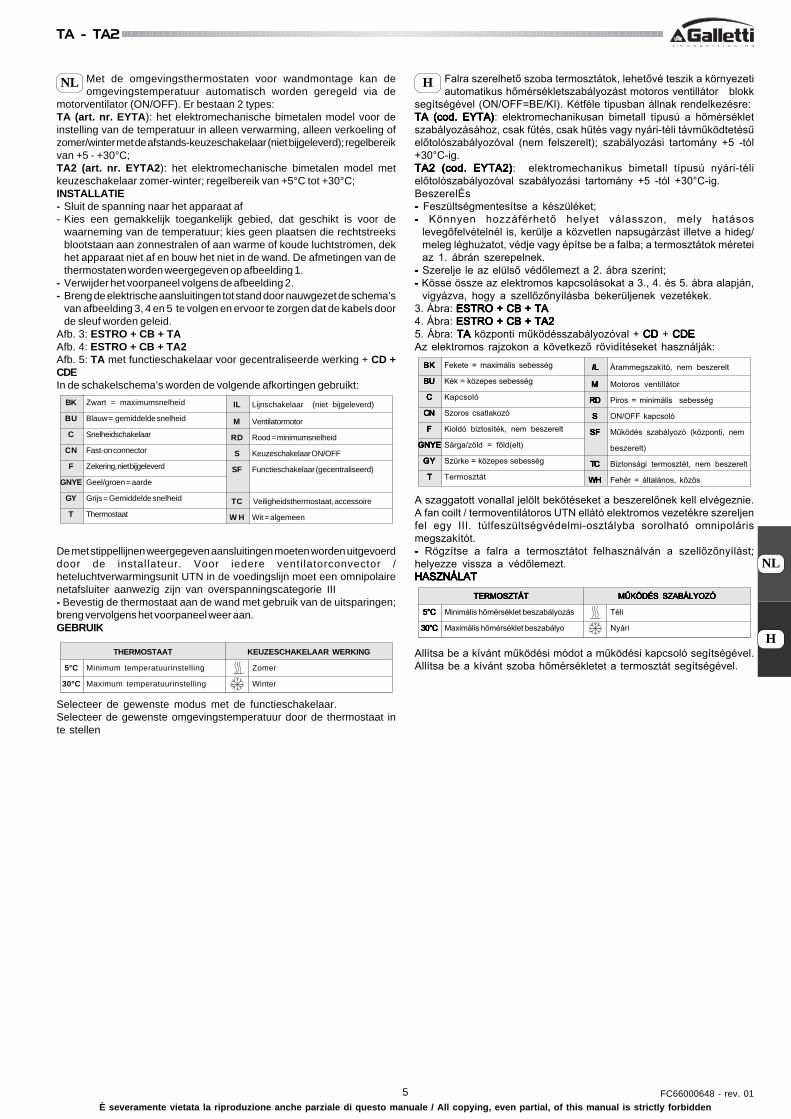
NL HMet de omgevingsthermostaten voor wandmontage kan deomgevingstemperatuur automatisch worden geregeld via de
motorventilator (ON/OFF). Er bestaan 2 types:TA (art. nr. EYTA): het elektromechanische bimetalen model voor deinstelling van de temperatuur in alleen verwarming, alleen verkoeling ofzomer/winter met de afstands-keuzeschakelaar (niet bijgeleverd); regelbereikvan +5 - +30°C;TA2 (art. nr. EYTA2): het elektromechanische bimetalen model metkeuzeschakelaar zomer-winter; regelbereik van +5°C tot +30°C;INSTALLATIE- Sluit de spanning naar het apparaat af- Kies een gemakkelijk toegankelijk gebied, dat geschikt is voor de
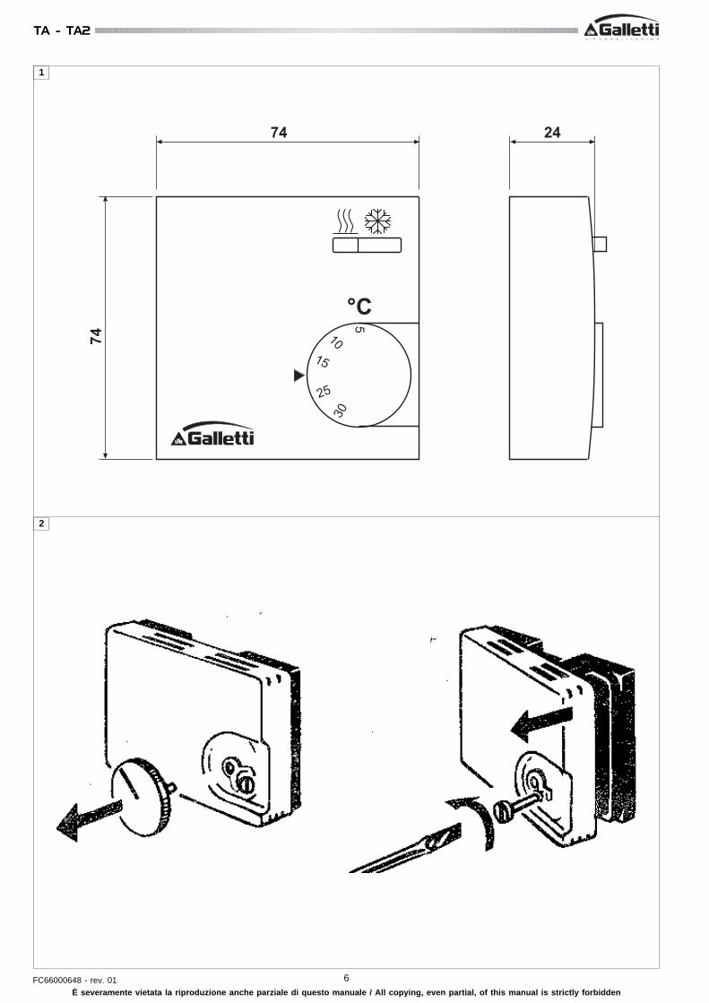
waarneming van de temperatuur; kies geen plaatsen die rechtstreeksblootstaan aan zonnestralen of aan warme of koude luchtstromen, dekhet apparaat niet af en bouw het niet in de wand. De afmetingen van dethermostaten worden weergegeven op afbeelding 1.
- Verwijder het voorpaneel volgens de afbeelding 2.- Breng de elektrische aansluitingen tot stand door nauwgezet de schema’s
van afbeelding 3, 4 en 5 te volgen en ervoor te zorgen dat de kabels doorde sleuf worden geleid.
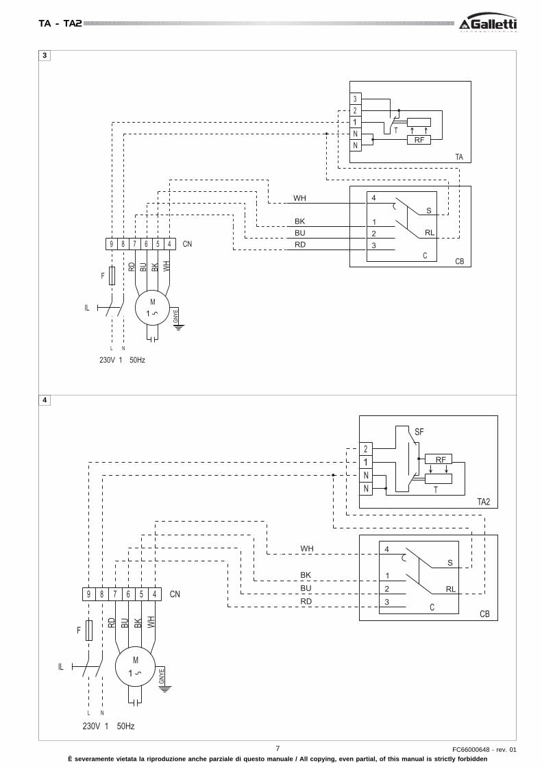
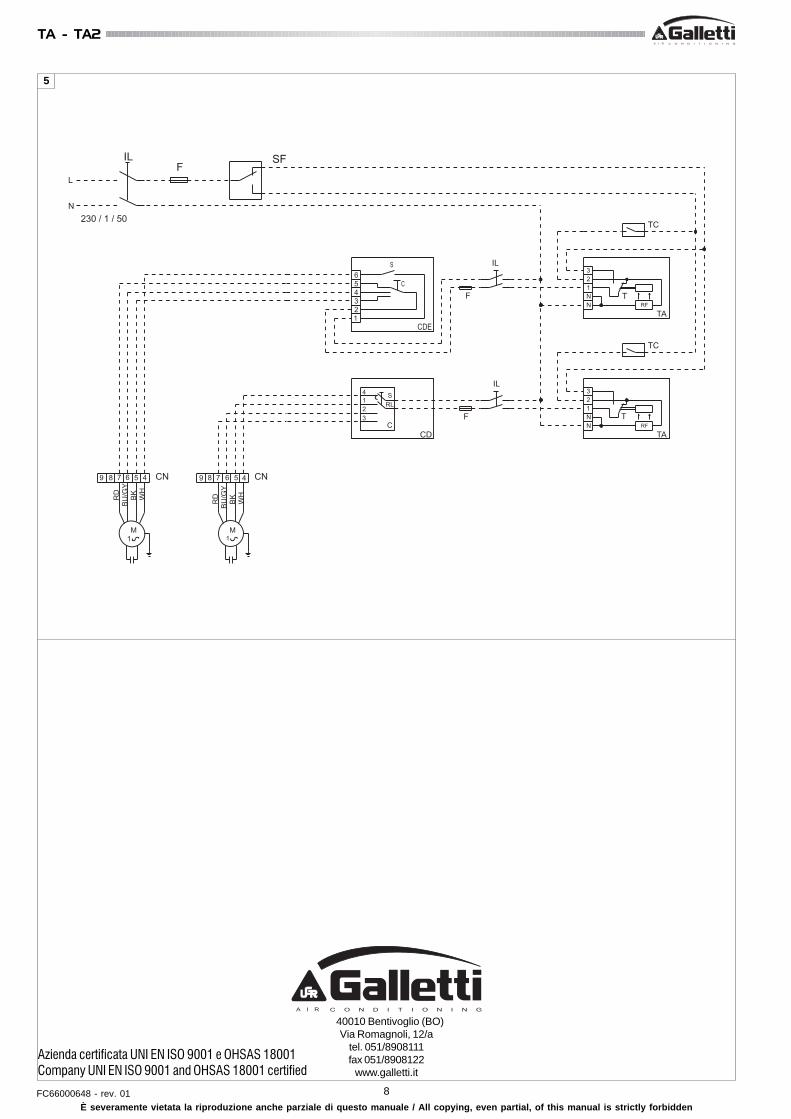
Afb. 3: ESTRO + CB + TAAfb. 4: ESTRO + CB + TA2Afb. 5: TA met functieschakelaar voor gecentraliseerde werking + CD +CDEIn de schakelschema’s worden de volgende afkortingen gebruikt:
De met stippellijnen weergegeven aansluitingen moeten worden uitgevoerddoor de installateur. Voor iedere ventilatorconvector /heteluchtverwarmingsunit UTN in de voedingslijn moet een omnipolairenetafsluiter aanwezig zijn van overspanningscategorie III- Bevestig de thermostaat aan de wand met gebruik van de uitsparingen;breng vervolgens het voorpaneel weer aan.GEBRUIK
Selecteer de gewenste modus met de functieschakelaar.Selecteer de gewenste omgevingstemperatuur door de thermostaat inte stellen
BK Zwart = maximumsnelheid
BU Blauw = gemiddelde snelheid
C Snelheidschakelaar
CN Fast-on connector
F Zekering, niet bijgeleverd
GNYE Geel/groen = aarde
GY Grijs = Gemiddelde snelheid
T Thermostaat
IL Lijnschakelaar (niet bijgeleverd)
M Ventilatormotor
RD Rood = minimumsnelheid
S Keuzeschakelaar ON/OFF
SF Functieschakelaar (gecentraliseerd)
TC Veiligheidsthermostaat, accessoire
W H Wit = algemeen
H
NL
THERMOSTAAT
5°C Minimum temperatuurinstelling
30°C Maximum temperatuurinstelling
KEUZESCHAKELAAR WERKING
Zomer
Winter
6FC66000648 - rev. 01
TA - TA2
È severamente vietata la riproduzione anche parziale di questo manuale / All copying, even partial, of this manual is strictly forbidden
��
��
��
���
��
��
��
��
2
1
7 FC66000648 - rev. 01
TA - TA2
È severamente vietata la riproduzione anche parziale di questo manuale / All copying, even partial, of this manual is strictly forbidden
�������������
� � � � �
��
���
�
� �
�
��
�
��
�
�
�
�
��
��
��
��
�����
��
��
��
!
�� �� �� �
3
4
�������������
� � � � �
��
���
�
� �
�
��
����
��
�
�
��
�
�
�
�
�
��
��
����
��
!�
��
�� �� �� �
8FC66000648 - rev. 01
TA - TA2
È severamente vietata la riproduzione anche parziale di questo manuale / All copying, even partial, of this manual is strictly forbidden
�
���
�
� � � � �
��
��
��
��
��"��
��
�
� � � � �
��
��
��
��"��
��
�
������
�
�
���
����
���
���
�����
��
!
�
�
�����
��
!
��
��
�
�
����"���"���
40010 Bentivoglio (BO)Via Romagnoli, 12/a
tel. 051/8908111fax 051/8908122
www.galletti.it
5
Azienda certificata UNI EN ISO 9001 e OHSAS 18001Company UNI EN ISO 9001 and OHSAS 18001 certified