Self-Study Programme 263 - Free
60
Polo Model Year 2002 Self-Study Programme 263 Service.
Transcript of Self-Study Programme 263 - Free

Polo Model Year 2002
Self-Study Programme 263
Service.

2
New ImportantNote
The visual appearance of the new Polo features the 4-eyed face with round headlights and the hatchback.
The new Polo again sets news standards in its class by offering improved spatial comfort, inno-vative state-of-the-art technology and all-round safety. It also meets high quality standards.
In this Self-Study Programme, we will present the new technical features and innovations of the new Polo.
The following Self-Study Programmes relating to the Polo 2002 are also available:SSP 259 "Electro-hydraulic Power Steering"SSP 260 "1.2-litre 3-cylinder Petrol Engines"SSP 264 "Brake Assistant System (BAS)"SSP 265 "Vehicle Electrical System in Polo Model Year 2002"
263_099
263_100
This Self-Study Programme explains the
design and function of new developments!
The contents are not updated.
Please always refer to the relevant Service Literature
for current inspection, adjustment and repair instructions.

3
At a glance
Summary . . . . . . . . . . . . . . . . . . . . . . . . . . . . . . . . . . . . . . . . . . . . 4
Body . . . . . . . . . . . . . . . . . . . . . . . . . . . . . . . . . . . . . . . . . . . . . . . . 6
Occupant protection . . . . . . . . . . . . . . . . . . . . . . . . . . . . . . . . . . 10
Engines . . . . . . . . . . . . . . . . . . . . . . . . . . . . . . . . . . . . . . . . . . . . . 14
Power transmission . . . . . . . . . . . . . . . . . . . . . . . . . . . . . . . . . . . 28
Running gear . . . . . . . . . . . . . . . . . . . . . . . . . . . . . . . . . . . . . . . . 30
Electrical system. . . . . . . . . . . . . . . . . . . . . . . . . . . . . . . . . . . . . . 39
Heater, air conditioning system . . . . . . . . . . . . . . . . . . . . . . . . . 44
Service . . . . . . . . . . . . . . . . . . . . . . . . . . . . . . . . . . . . . . . . . . . . . 56

4
The Polo Model Year 2002 is available in 2-door and 4-door body versions.The vehicle is at the cutting edge with regard to safety, quality, performance, running gear and equipment.
Summary
263_091
A vehicle electrical system control unit is responsible for load management of elec-trical system components. It monitors automotive components not integrated in the two CAN bus systems.
Easy entry seats with memory function facilitate access to the rear seats.
A semi-automatic air conditioning system - Climatic - ensures a pleasant climate inside the passenger cabin.
An electro-hydraulic power steering sys-tem provides needs-oriented steering assistance.
Two low-emission 3-cylinder petrol engines are available as entry-level units.
A hydraulic brake assistant sys-tem (BAS) assists the driver with braking in hazardous situations.
The front end obtains a certain friendly appearance from the round front headlights.
5
Dimensions and weights
Length 3897 mm
Width 1650 mm
Height 1465 mm
Wheelbase 2460 mm
Turning circle 10,6 m
Tank capacity 45 l
263_086
3897 mm
2460 mm
1650 mm
1465
mm
75 kg
Front track width 1435 mm
Rear track width 1425 mm
Max. permissible gross weight
1560 kg*
Kerb weight 1025 kg*
Max. permissible roof load 75 kg
Drag coefficient c
d
0,32
* Specifications refer to a 2-door Polo
with 1.4-litre 55 kW engine and manual gearbox
6
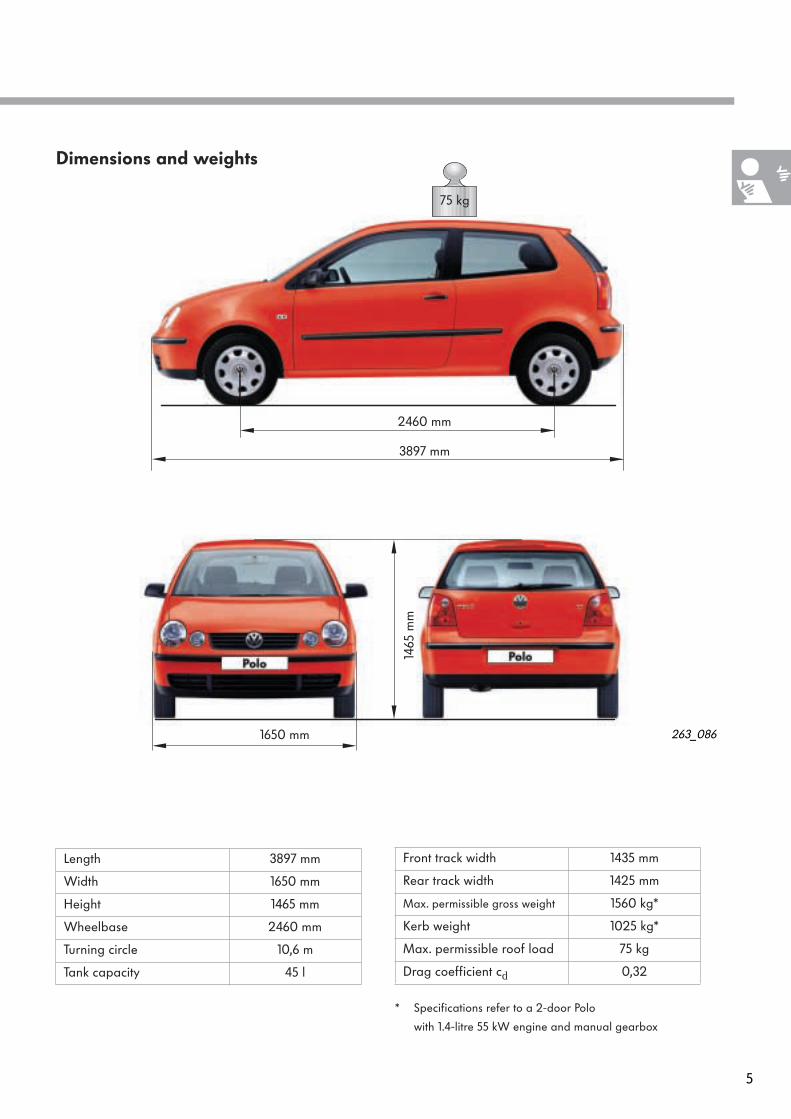
A new technique is used to join the bonnet and tailgate. The sheet-metal panels are joined by clinching. Advantages:
– Uniform appearance– Low-cost method
Clinching entails press-fitting metal sheets together by means of a mould and a plunger.
Body
Body
The body of the Polo is fully galvanised and partly consists of high-strength panels.The front and rear side members, the B pillars and the front left and right floor pans are made of high-strength sheet metal.By increasing body rigidity, the shutlines of the doors and flaps have been reduced still further.
By optimising the design of the front, rear and lateral crash areas, occupant safety has again been increased.
263_102
263_105

7
263_094
263_121
The doors and lids of the new Polo are made of Bonazink panels.Bonazink is a trade name for a type of sheet metal with a thin-film coating.The thin-film coating is based on a zinc-pig-mented epoxy resin system.This allows us to reduce the use of PVC for fine seam sealing.
The body side panels and the roof are joined together by a laser-welded seam.This does away with the sealing work otherwise required after spot welding
Laser weld seam
Roof Side body panel
8
Body
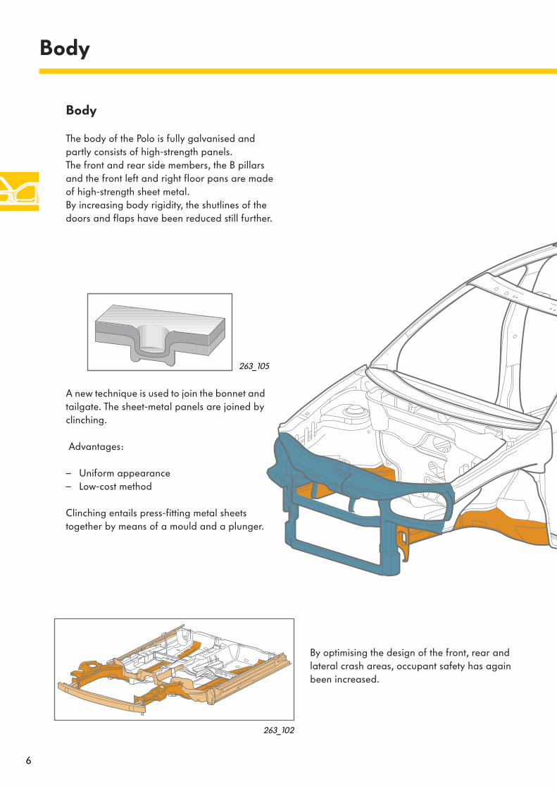
Underbody panelling
This is made of plastic and protects the rear end of the vehicle underbody.Because of its special shape, the underbody panelling keeps flying stone chips away from the body. There is no longer any need for a PVC coating in the rear underbody area.
Hinged (rear) windows
The rear side windows for the 2-door Polo are available as hinged windows.
Fuel filler flap
It is operated in the same way as a push-button.
– To open, press the fuel filler flap– To close, push back the fuel filler flap until
it snaps into place.
263_095
263_090
Underbody panelling
Underbody panelling
263_089

9
Front seats
The front seats for the 2-door Polo are available optionally with an easy entry facility and a manual memory function.
Integrated in the sill-side rail is a so-called memory block which moves back and forth together with the seat when the longitudinal adjustment is released by locks 1 and 2.
The rear seats can be accessed by unlocking the front seat backrest and folding it forwards as usual. The seat can be pulled forward at the same time for easier access to the rear seats (easy entry function). The memory chip remains in position (memory position) as the locks in the longitudinal follower are released when the backrest is folded forward.
The seat can be pulled back to its initial position (memory position) after the backrest is folded back. The seat then locks automatically due to the memory chip, the locking lever and the strike stop on the slide rail (seat).
263_142
263_143
263_144
Strike stopSlide rail (seat)
Memory chip Locking lever
Lock 1
Lock 2 Memory chip
Locking lever
263_124
263_126
263_125
Locking lever engaged

10
Occupant protection
Occupant protection
Occupant protection is assured by the airbag system. It comprises two front airbags, side and head airbags, seat belts and belt tensioners, as well as the child restraint system.
Side airbagfront passenger
Front airbagfront passenger
Front airbagfront passengermodule
Front airbagdrivermodule
Airbagcontrol unit
Crash sensorside airbagdriver
Side airbag module
Front airbagdriver
The Polo Model Year 2002 has two full-size front airbags on the driver and front passenger sides with filling volumes of 64 and 120 litres respec-tively. The central airbag control unit is located behind the central console, on the tunnel.
The side airbags are integrated in the front seats and have a filling volume of 12 litres. The head airbags have a filling volume of 23 litres each and are installed in the vehicle head-lining above the doors.
The airbag sensor system comprises two lateral acceleration sensors (vehicles with head airbags have four lateral acceleration sensors). They are located below the front seats.
Crash sensorside airbagfront passenger

11
263_057
Head airbagmodule
Head airbag(to be launched later)
Inertia reel seat belt
Ball-type tensioner
Side airbagdriver
Side airbagmodule
Seat with integratedside airbag
Standard inertia-reel seat belts are employed in the outer front and rear seating positions.In the front seating positions, ball-type tensioners are fitted.
In vehicles without side airbags, the belt tension-ers are triggered mechanically and pyrotechni-cally.In vehicles equipped with side airbags, the belt tensioners are triggered electrically and pyro-technically.
In the new Polo, the front passenger air-bag can be deactivated by a key switch.
Three-point seat belt

12
Occupant protection
Deactivation of front passenger's airbag
Airbag switch
A key switch for deactivating the front and side airbags for the front passenger is located in the glove compartment.
To deactivate these airbags, the airbag switch must be turned to the "OFF" position using the ignition key.
"AIRBAG OFF" indicator lamp
When the front passenger airbags are deacti-vated, the "AIRBAG OFF" indicator lamp comes on when the ignition is turned on.
If a fault occurs in the airbag system, the indicator lamp begins to flash.
263_120
The airbag switch may only be operated when the ignition is OFF.
263_119
13
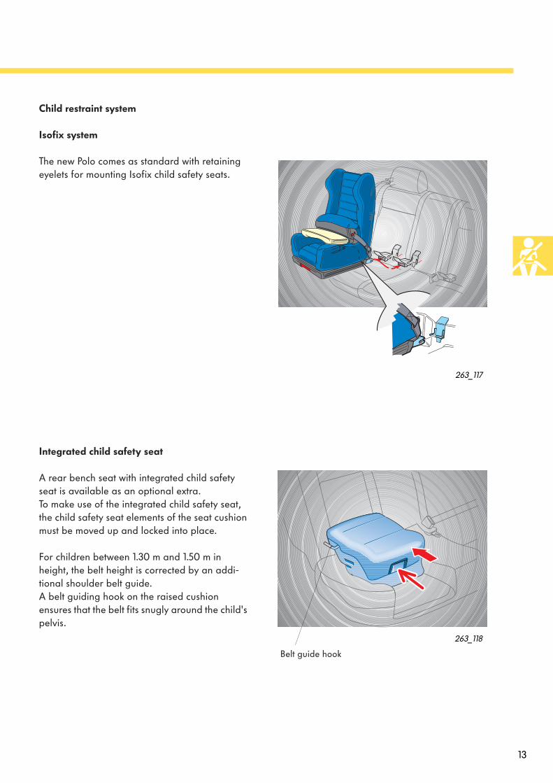
Child restraint system
Isofix system
The new Polo comes as standard with retaining eyelets for mounting Isofix child safety seats.
Integrated child safety seat
A rear bench seat with integrated child safety seat is available as an optional extra.To make use of the integrated child safety seat, the child safety seat elements of the seat cushion must be moved up and locked into place.
For children between 1.30 m and 1.50 m in height, the belt height is corrected by an addi-tional shoulder belt guide.A belt guiding hook on the raised cushion ensures that the belt fits snugly around the child's pelvis.
263_117
263_118
Belt guide hook
14
All petrol engines comply with the EU4 exhaust emission standard. The TDI diesel engine with unit injector system conforms to the D4 exhaust emission standard.
In the Federal Republic of Germany, owners of vehicles which conform to the D4 or EU4 exhaust emission standard receive financial incentives from the government.
As compliance with the D4 and EU4 exhaust emission standard involves higher technical com-plexity, the engines are supplied in several coun-tries in slightly modified versions. They are compliant with a different exhaust emission stan-dard.
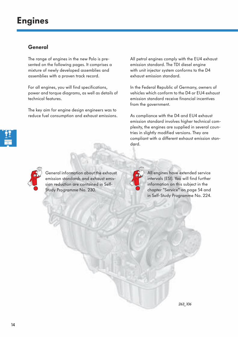
Engines
General
The range of engines in the new Polo is pre-sented on the following pages. It comprises a mixture of newly developed assemblies and assemblies with a proven track record.
For all engines, you will find specifications, power and torque diagrams, as well as details of technical features.
The key aim for engine design engineers was to reduce fuel consumption and exhaust emissions.
All engines have extended service intervals (ESI). You will find further information on this subject in the chapter "Service" on page 54 andin Self-Study Programme No. 224.
263_106
General information about the exhaust emission standards and exhaust emis-sion reduction are contained in Self-Study Programme No. 230.

15
Engine code AWY
Displacement 1198 cc
Type 3-cylinder inline engine
Valves per cylinder 2
Bore 76,5 mm
Stroke 86,9 mm
Compression ratio 10,3 : 1
Max. power 40 kW at 4750 rpm
Max. torque 106 Nm at 3000 rpm
Engine management Simos 3PD
Fuel 95 RON unleaded premium (91 RON unleaded petrol can be used alternatively. This reduces performance slightly)
Exhaust treatment Three-way catalyst with lambda regulation
Exhaust emission standard EU4 (1/min)
1000 50002000 3000 4000
20
30
40
50
60
70
6000 7000
140
100
80
120
0
The 1.2-litre 40 kW 3-cylinder petrol engine with 2-valve technology
The 1.2-litre engine is the first 3-cylinder petrol engine to be built by Volkswagen.
Technical features - Engine mechanicals
– Air filter integrated in engine cover – Chain driven camshaft– Split cylinder block – Crankshaft drive with balancer shaft – Crossflow cooling in cylinder head– Upright oil filter– Crankcase ventilation
Technical features - Engine management
– Single-spark ignition coils with integrated power output stage
– Exhaust treatment with near-engine catalyst and two non-linear lambda sensors
More detailed information about this engine is contained in Self-Study Pro-gramme No. 260 - 1.2-litre 3-cylinder petrol engines.
263_001
Power/torque diagramSpecifications
263_016
Engine speed
Torq
ue
Pow
er o
utpu
t

16
Engine code AZQ
Displacement 1198 cc
Type 3-cylinder inline engine
Valves per cylinder 4
Bore 76,5 mm
Stroke 86,9 mm
Compression ratio 10,5 : 1
Max. power 47 kW at 5400 rpm
Max. torque 112 Nm at 3000 rpm
Engine management Simos 3PE
Fuel 95 RON unleaded premium (91 RON unleaded can be used alternatively. This reduces per-formance slightly)
Exhaust treatment Three-way catalyst with lambda regulation, exhaust gas recirculation
Exhaust emission standard EU4
Engines
The 1.2-litre 47 kW 3-cylinder petrol engine with 4-valve technology
4-valve technology distinguishes this engine from the 1.2-litre 40 kW engine.
Technical features - Engine mechanicals
– Air filter integrated in engine cover– Chain driven camshaft– Split cylinder block– Crankshaft drive with balancer shaft– Crossflow cooling in the cylinder head– Upright oil filter– Non-return fuel system– Crankcase ventilation
Technical features - Engine management
– Single-spark ignition coil with integrated power output stage
– Electrical EGR valve– Exhaust treatment with near-engine catalyst,
broadband lambda probe and non-linear lambda probe
263_015
More detailed information about this engine can be found in Self-Study Pro-gramme No. 260 - 1.2-litre 3-cylinder petrol engines.
Power/torque diagram
20
30
40
50
60
70
6000 7000
140
100
80
120
80
(1/min)1000 50002000 3000 40000
263_002
Specifications
Engine speed
Torq
ue
Pow
er o
utpu
t

17
Engine code AUA/BBY
Displacement 1390 cc
Type 4-cylinder inline engine
Valves per cylinder 4
Bore 76,5 mm
Stroke 75,6 mm
Compression ratio 10,5 : 1
Max. power 55 kW at 5000 rpm
Max. torque 126 Nm at 3800 rpm
Engine management Magneti Marelli 4MV
Fuel 95 RON unleaded premium (91 RON unleaded petrol can be used alternatively. This reduces performance slightly)
Exhaust treatment Primary catalyst, main catalyst with lambda regulation, exhaust gas recirculation
Exhaust emission standard EU4 (1/min)
1000 50002000 3000 4000
20
30
40
50
60
70
6000 7000
140
100
80
120
0
The 1.4-litre 55 kW 4-cylinder petrolengine with 4-valve technology
The 1.4-litre 55 kW engine with engine code AUA will be launched in combination with the manual gearbox. This engine, however, already has a non- return fuel system.A more advanced 1.4-litre 55 kW engine with engine code BBY will be introduced at a later date.This engine (BBY) is available at launch in con-junction with the automatic gearbox.
Technical new features - Engine mechanicals
– Air filter integrated in engine cover– Non-return fuel system– Crankcase ventilation
Technical new features - Engine management
– Single-spark ignition coil– Electrical EGR valve
263_018
Power/torque diagram
Engine speed
Torq
ue
Pow
er o
utpu
t
Specifications
263_127

18
Engines
The 1.4-litre 74 kW 4-cylinder petrolengine with 4-valve technology
This engine is an advanced development of the1.4-litre 74 kW engine from the previous model.
Technical new features - Engine mechanicals
– Air filter integrated in engine cover– Non-return fuel system– Crankcase ventilation– Plastic intake manifold
Technical new features - Engine management
– Single-spark ignition coil– Electrical EGR valve
263_127
Engine code BBZ
Displacement 1390 cc
Type 4-cylinder inline engine
Valves per cylinder 4
Bore 76,5 mm
Stroke 75,6 mm
Compression ratio 10,5 : 1
Max. power 74 kW at 6000 rpm
Max. torque 126 Nm at 4400 rpm
Engine management Magneti Marelli 4LV
Fuel 95 RON unleaded premium (91 RON unleaded petrol can be used alternatively. This reduces performance slightly)
Exhaust treatment Primary catalyst, main catalyst with lambda regulation, exhaust gas recirculation
Exhaust emission standard EU4 (1/min)
1000 50002000 3000 4000
20
30
40
50
60
70
6000 7000
140
100
80
120
0
263_019
Power/torque diagramSpecifications
Engine speed
Torq
ue
Pow
er o
utpu
t

19
Crankcase breather
The crankcase breather is used in all petrol engines.
The system consists of:
– an oil separator– a diaphragm valve– a plastic hose, and– a tube with a non-return valve for
ventilation purposes (on the air filter)
The crankcase breather prevents oil and unburned hydrocarbons from being expelled into the envi-ronment.Crankcase ventilation is improved by inducing additional fresh air. This reduces condensation, and dramatically improves oil quality and anti-freezing protection.
Diaphragm valve
Ensures that the pressure level inside the crank-case stays constant and that the crankcase is well-ventilated. This valve is divided into two chambers by a diaphragm. One chamber leads out into the open air and the other is connected to the intake pipe.
– At a high intake manifold vacuum (e. g. when the engine is idling), the diaphragm is drawn towards the port cross section in the opposite direction to the spring pressure. As a result, less gas is drawn out of the crankcase.
Fresh air supply from the air filter
Diaphragm valve
Oil separator
263_079
Plastic hose
263_052
– At a low intake pipe vacuum (e. g. at full throttle), the spring pushes the membrane back. As a result, the port cross-section is open wide and more gas is sucked out of the crankcase.
from the crankcase
Fresh airinlet
263_053

20
M
Engines
Non-return fuel system
The non-return fuel system is used in all petrol engines, with the exception of the 1.2-litre 40 kW engine.
The fuel is delivered from the electrical fuel pump to the fuel filter. Once in the fuel filter, the fuel flows to the fuel rail and the injectors.
The fuel pressure is a constant 3 bar, and is regulated by the fuel pressure regulator in the fuel filter.
263_054
Electrical fuel pump
Fuel filter
Fuel rail
Injectors
Air bleed valve
In the non-return fuel system there is no return line from the fuel rail to the fuel tank.
In the non-return fuel system, there is an air bleed valve on the fuel rail. You must bleed the system after working on the system. Please follow the instructions given in the Workshop Manual.
Fuel pressure regulator

21
Fuel filter with fuel pressure regulator
The fuel filter is located on the right-hand side of the fuel tank.
The fuel pressure regulator is connected to the fuel filter and secured with a retaining clip. It keeps the fuel pressure in the fuel system at a constant 3 bar.
The function of the fuel pressure regulator:
The electrical fuel pump delivers the fuel into the fuel filter chamber. There, the fuel is filtered and flows to the fuel rail and to the injectors.
The fuel pressure of 3 bar is adjusted by a spring-loaded diaphragm valve in the fuel pres-sure regulator. When the pressure exceeds 3 bar, the diaphragm valve opens up the return line to the fuel tank.
263_055
263_031
Fuel filter chamberFuel filter Fuel pressure regulator
Fuel return lineto fuel tank
Fuel supply line from fuel tank
Fuel supply line to fuel rail
Fuel filterFuel pressure regulator
Securing clip for pressure regulator

22
The 1.9-litre 47 kW SDI engine
This engine was adopted from the previous model.
Engines
263_021
263_022 (1/min)
1000 50002000 3000 4000
20
30
40
50
60
70
6000
140
100
80
120
0
160
180
200
220
240
Specifications
Engine speed
Torq
ue
Pow
er o
utpu
t
Power/torque diagram
Engine code ASY
Displacement 1896 cc
Type 4-cylinder inline engine
Valves per cylinder 2
Bore 79,5 mm
Stroke 95,5 mm
Compression ratio 19 : 1
Max. power 47 kW at 4000 rpm
Max. torque 125 Nm at 2200 - 2600 rpm
Engine management Bosch EDC 15 V
Fuel Diesel (min. 49 CN diesel or biodiesel)
Exhaust treatment Exhaust gas recirculation andoxidising catalyst
Exhaust emission standard D3

23
The 1.4-litre 55 kW 3-cylinder TDI engine with unit injector system
This engine is an advanced development of the 1.4-litre 55 kW TDI engine from the previous model.
To meet the D4 exhaust emission standard, the fol-lowing innovations were employed:
– new unit injector design– exhaust gas recirculation with electrically-actu-
ated intake manifold flap– nitrous oxide emissions were reduced by using
an exhaust gas recirculation cooler– the combustion sequence was improved by
modifying the combustion chamber
263_026 (1/min)
1000 50002000 3000 4000
20
30
40
50
60
70
6000
140
100
80
120
0
160
180
200
220
240
Specifications
Engine speed
Torq
ue
Pow
er o
utpu
t
263_025
The design and function of the 1.4-litre 55 kW 3-cylinder TDI engine are explained in Self-Study Programme No. 223.
Power/torque diagram
Engine code BAY
Displacement 1422 cc
Type 3-cylinder inline engine
Valves per cylinder 2
Bore 79,5 mm
Stroke 95,5 mm
Compression ratio 19,5 : 1
Max. power 55 kW at 4000 rpm
Max. torque 195 Nm at 2200 rpm
Engine management Bosch Electronic Damper Control 15
P
Fuel Diesel min. 49 CN diesel or biodiesel (RME)
Exhaust treatment Exhaust gas recirculation andoxidising catalyst
Exhaust emission standard D4

24
Engine codes AXR
Displacement 1896 cc
Type 4-cylinder inline engine
Valves per cylinder 2
Bore 79.5 mm
Stroke 95.5 mm
Compression ratio 19 : 1
Max. power 74 kW at 4000 rpm
Max. torque 240 Nm at 1800 - 2400 rpm
Engine management Bosch Electronic Damper Control 15 P
Fuel Diesel min. 49 CN diesel or biodiesel
Exhaust treatment Exhaust gas recirculation andoxidising catalyst
Exhaust emission standard D4
Engines
The 1.9-litre 74 kW 4-cylinder TDI engine with unit injector system
This engine is an advanced development of the 1.9-litre 74 kW engine from the previous model.
To meet the D4 exhaust emission standard, the fol-lowing innovations were employed:
– new unit injector design– exhaust gas recirculation with electrically-actu-
ated intake manifold flap– nitrous oxide emissions were reduced by using
an exhaust gas recirculation cooler– the combustion sequence was improved by
modifying the combustion chamber– the oxidising catalyst is of thin wall design so
that it quickly reaches its operating temperature
263_024 (1/min)
1000 50002000 3000 4000
20
30
40
50
60
70
6000
140
100
80
120
0
160
180
200
220
240
Power/torque diagram
Specifications
Engine speed
Torq
ue
Pow
er o
utpu
t
263_023

25
New features of unit injector
To meet the requirements with regard to extended service intervals and exhaust emission reduction, the unit injector has been improved in the following respects.
263_108 263_109
Previousversion
Newversion
Inlet drilling

26
Electrical intake manifold flap
The 1.4-litre and 1.9-litre TDI engines with unit injector system have an electrical intake manifold flap so they meet the strict emission limits of the D4 exhaust emission standard. Because adjust-ment of the electrical intake manifold flap is con-tinuously variable, the vacuum required for effective exhaust gas recirculation can be achie-ved in all engine speed ranges.
The electrical intake manifold flap also has a second function. When the engine is shut off, the flap is closed to stop air supply and prevent engine shudder when it cuts out.
Design
Engines
Control electronics
Flap return spring
Intake manifold flap
Intake manifold flap motor V157
263_008
263_009

27
Function
To adjust the intake manifold flap, the engine control unit sends a signal to the intake manifold flap motor (V157). An angle sensor measures the actual intake manifold flap angle. The internal control electronics process the signal and adjust the flap to the specified angle via the drive system.
A flap return spring permits emergency opera-tion by keeping the intake manifold flap open when de-energised.
263_141Engine control unit
Intake manifold flap motor V157
Intake manifold flap
Flap return spring
263_159
Cooler for exhaust gas recirculation
The 1.4-litre and 1.9-litre TDI engines have a cooler for exhaust gas recirculation. This cooler is coupled to the coolant circuit. By cooling the recirculated exhaust gases, a higher volume of exhaust gas can be discharged into the combu-stion chamber. This reduces combustion tempera-ture and nitrogen oxide emissions.
28
Power transmission
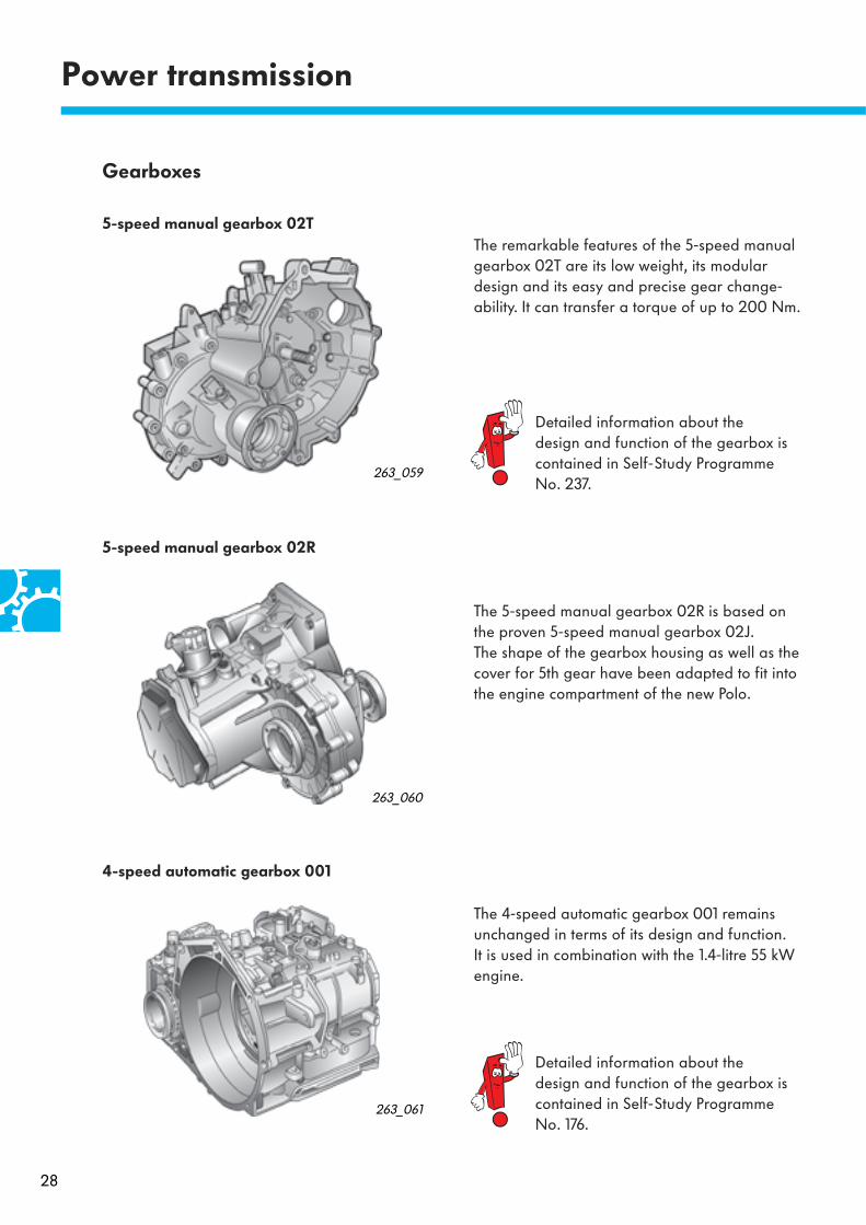
The 4-speed automatic gearbox 001 remains unchanged in terms of its design and function. It is used in combination with the 1.4-litre 55 kW engine.
The 5-speed manual gearbox 02R is based on the proven 5-speed manual gearbox 02J.The shape of the gearbox housing as well as the cover for 5th gear have been adapted to fit into the engine compartment of the new Polo.
The remarkable features of the 5-speed manual gearbox 02T are its low weight, its modular design and its easy and precise gear change-ability. It can transfer a torque of up to 200 Nm.
5-speed manual gearbox 02T
5-speed manual gearbox 02R
4-speed automatic gearbox 001
263_060
263_059
263_061
Detailed information about the design and function of the gearbox is contained in Self-Study Programme No. 237.
Detailed information about the design and function of the gearbox is contained in Self-Study Programme No. 176.
Gearboxes

29
Engine-gearbox combinationsEngine 5-speed
manual gearbox02T
5-speedmanual gearbox02R
4-speedautomatic gearbox001
1.2-litre 40 kW
Petrol engine
AWY
1.2-litre 47 kW
Petrol engine
AZQ
1.4-litre 55 kW
Petrol engine
AUA/BBY
1.4-litre 74 kW
Petrol engine
BBZ
1.9-litre 47 kW
SDI engine
ASY
1.9-litre 74 kW
TDI engine
AXR
1.4-litre 55 kW
TDI engine
BAY

30
Running gear
263_030
Aluminium console
Aluminium console
Subframe
The front axle
The front axle of the new Polo is a MacPherson strut axle with a wishbone. It has been improved with regard to weight and comfort.
Front strut wishbone suspension
263_156
Front strut wishbone suspension
Metal
Rubberelement
Wishbone
Technical features
– Weight has been saved by using a three-part subframe with a sheet steel subframe, alumin-ium consoles and sheet steel wishbones.
– The front strut wishbone suspension is a bonded rubber bush. The springs and shock absorbers are connected separately to the body. Through this concept, spring pressure is applied separately to the body, and the shock absorber mounting is not submitted to initial stress. This, in turn, enhances rolling comfort and reduces noise transmission from the road to the body.
Spring connection
Shock absorber connection
31
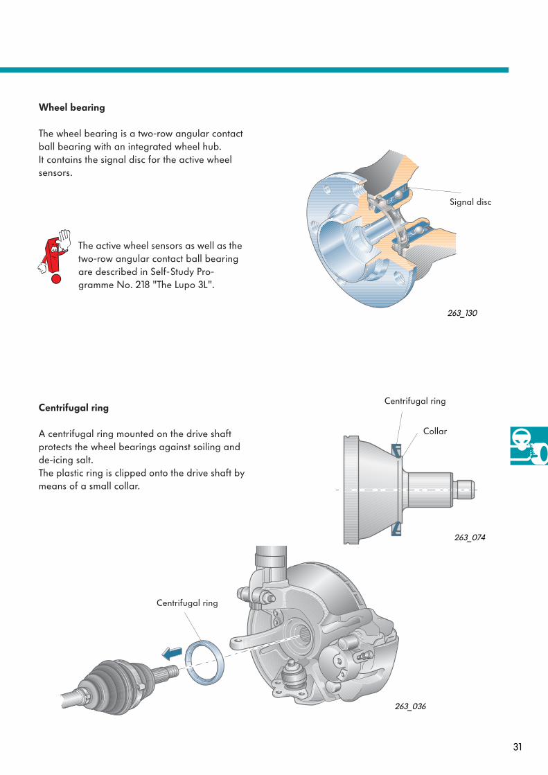
Centrifugal ring
A centrifugal ring mounted on the drive shaft protects the wheel bearings against soiling and de-icing salt.The plastic ring is clipped onto the drive shaft by means of a small collar.
263_130
Wheel bearing
The wheel bearing is a two-row angular contact ball bearing with an integrated wheel hub. It contains the signal disc for the active wheel sensors.
The active wheel sensors as well as the two-row angular contact ball bearing are described in Self-Study Pro-gramme No. 218 "The Lupo 3L".
263_074
263_036
Signal disc
Centrifugal ring
Collar
Centrifugal ring

32
Running gear
Technical features
– A specially-shaped axle beam with a V cross-section provides the axle with high stability. A separate anti-roll bar is therefore not nee-ded.
– Coil springs and shock absorbers are located separately from one another, in order to maximise loading width.
– The rear axle is secured to the body by inclined, track-aligning and large-sized bonded rubber bushes. The inclination of the bearings corrects track alignment when late-ral forces occur. It provides added driving stability, particularly at high road speeds.
263_032
Rear axle
The rear axle is a torsion beam axle. As an all-new construction, it makes a substantial contribu-tion to weight saving.
Toe and camber are defined by the structural design. There is no facility for adjusting the rear axle.

33
Axle beam cross-sections
A specially-shaped axle beam with a V cross-section endows the axle with high stability. An anti-roll bar is therefore not needed. The axle beam is made by reshaping a tube.
There are three axle beams with varying degrees of rigidity. They are adapted to each engine type.The differences in axle beam profile rigidity are due to the different wall thicknesses and geome-tries.
Steering column
The steering column is of safety design.It compresses on collision and optimises the posi-tion of the airbag in relation to the driver.
Longitudinal adjustment
The steering column has a manually adjustable length of 45 mm.
Height adjustment
The steering column can be adjusted for height by 46 mm.
46 mm
263_028
263_115
263_103
45 mm

34
Running gear
Electro-hydraulic power steering
The electro-hydraulic power steering is a new steering system with a hydraulic pump driven by an electric motor.
The power steering, therefore, is independent of the engine operating state. It permits needs-ori-entated power steering. This makes the vehicle easier to maneouvre and saves fuel.
The Polo Model Year 2002 features electro-hyd-raulic power steering in the entry-level version. Steering systems manufactured by TRW and KOYO are fitted.Both steering systems function according to the same principle.
The design and function of the electro-hydraulic power steering are described in detail in Self-Study Programme No. 259.
Power steering box
Engine pump unit
Sensor for power steering
263_033
35
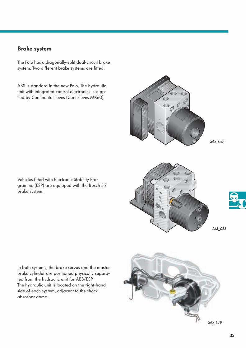
Brake system
The Polo has a diagonally-split dual-circuit brake system. Two different brake systems are fitted.
ABS is standard in the new Polo. The hydraulic unit with integrated control electronics is supp-lied by Continental Teves (Conti-Teves MK60).
Vehicles fitted with Electronic Stability Pro-gramme (ESP) are equipped with the Bosch 5.7 brake system.
In both systems, the brake servos and the master brake cylinder are positioned physically separa-ted from the hydraulic unit for ABS/ESP. The hydraulic unit is located on the right-hand side of each system, adjacent to the shock absorber dome.
263_088
263_087
263_078

36
Hydraulic Brake Assistant System (BAS)
This is integrated in the ABS/ESP unit.Accident research has shown that the majority of drivers do not apply the brakes sufficiently in a hazardous situation. Consequently, the brake pressure is insufficient to achieve maximum vehicle deceleration.
Pressure sensor G201 determines the pressure gain within the brake system. The control unit recog-nises an emergency stop by an abrupt rise in brake pressure within a specific period of time. After detecting the emergency situation, the con-trol unit increases the brake pressure within the ABS control range. This shortens the vehicle's stopping distance, and the vehicle comes to a halt more quickly.
Running gear
The design and function of the hydraulic brake assistant system (BAS) are described in detail in Self-Study Programme No. 264.
263_006
263_005ABS control range
Normal braking operation
Emergency stop
Brak
e pr
essu
re [
p]
Pressure gain within brake system
Time [t]
Pressure sensor

37
Front brake
The front brakes on the Polo are 256 x 22 mm ventilated disc brakes.
The rear brakes on the Polo are drum brakes. All vehicles with engine outputs of less than 55 kW have 200 x 40 mm brake drums.
Polo models with an engine output higher than 55 kW have 232 x 9 mm disc brakes.
Rear brake
263_039
263_038
263_037

38
Running gear
263_101
The breakdown set is not delivered to all countries. Depending on national statutory requirements, vehicles can also be equipped with a space-saver spare wheel or a fully-fledged spare wheel instead of the breakdown set.
Breakdown set To save weight, the spare wheel will be replaced by a breakdown set. This set consists of an inflating bottle together with a tyre sealant and a compressor powered via the cigarette lighter.
In the event of a breakdown, the sealant is pressed out of the inflating bottle and into the tyres via the tyre valve. The tyre is reinflated with the compressor. The rolling motion of the tyres ensures an even distribution of sealant inside the tyre. The heat generated while travelling is sufficient to vulca-nise the sealant and the tyre.
In the event of minor damage, the tyre can be made serviceable using the breakdown set so that the vehicle can reach next workshop.The vehicle still has a full-size tool kit including a jack.

39
Vehicle electrical system
The vehicle electrical system has a decentralised configuration. The main stations are:
263_011
263_047
263_045
263_042 263_043
263_044
Vehicle electrical system control unit:takes over the functions of previously separate relays (e.g. indicator relays), and monitors the power sup-ply of electrical equipment and auto-motive components outside the CAN system (e.g. switches/fuses)
Main fuse holder:groups together the main fuses on the battery cover so they are easily accessible
Connector stations in A pillar and B pillar:for connecting or disconnecting electrical modules in the doors from the other parts of the vehicle electrical system
Fuse box:Groups together fuses on a holder
Detailed information about the electrics can be found in Self-Study Programme No. 265 "The vehicle electrical system in the Polo Model Year 2002".
Electrical system
Compact connector:connector station on the engine bulkhead for con-necting/disconnecting parts of the vehicle electri-cal system in the engine compartment and vehicle interior
263_041
263_046
Potential distributor:distributes terminal +30 of the main fuse holder to indi-vidual electrical consumers
1 2 3
5 6 7 8 9
11 12 13 14 15
4
10 263_157
Relay carrier:carries the relays for basic and optional equipment

40
J519
J104
J500
G85
J234
J285
J…
J217
J393
J255/ J301
J386
J387
J388
J389
J503
J533
Data interchange is organised via this integrated gateway.
CAN bus system network
The data bus diagnostic interface (gateway) plays a key role in the CAN bus system. It is inte-grated in the vehicle electrical system control unit and combines the two CAN bus systems.
Electrical system
263_104
Engine control unit
Automatic gearbox control unit
ABS and EDL control unit
Power steering control unit
ESP steering angle sender
Airbag control unit
Door control unit, rear right
Door control unit, rear left
Door control unit, front passenger side
Door control unit, driver side
CLIMAtronic control unit/air conditioning system control unit (Climatic)
Convenience system central control unit
Control unit for display unit in dash panel insert
Vehicle electrical system control unitData bus diagnosis interface (gateway)
Control unit forradio and navigationdisplay unit
= Engine CAN500 kBaud
= Convenience CAN100 kBaud
= K-wire

41
Dash panel insert A number of new warning and indicator lamps have been added to the display in connection with the launch of the new vehicle electrical system.
Display symbol
Designation/definition Display symbol
Designation/definition
Foglights Lamp comes on when foglights are switched on
Electronic immobiliserLamp comes on when unauthorised car key is used
Electro-hydraulic power steering Lamp comes on and stays on while steer-ing malfunctions
Brake pad wear indicator lamp Lamp comes on when brake linings reach their wear limit
Engine oil level/pressure (yellow/red)"Yellow" indicates problem with oil level, "red" indicates problem with oil pressure
Windscreen washer fluidLamp comes on when washer fluid level in the washer fluid tank drops below min. level
Cruise control systemLamp comes on when cruise control is on
Door openedLamp comes on when not all doors are locked
Rear seat back lockcomes on when the middle seat ofthe rear bench seat is not locked in posi-tion
Trailer indicator systemLamp flashes when direction indicator system is operating in trailer towing mode
263_040

42
Electrical system
Taillight
263_114
Flashing light(yellow bulb)
Stop light
Rear foglight/taillight
Reversing light
263_113
Headlights
The new headlights are of duplex design and have clear plastic lenses.
The headlight assembly has two reflectors. The reflector for the main beam and parking light consists of a single chamber. The reflector for the dipped beam and indicator is split into two cham-bers.
The bulb for the indicator is coloured yellow. Light is distributed by the shape of the reflector chamber.
The foglights are integrated in the bumper, not in the headlight assembly.
Taillights
The reflector consists of a single part and is divi-ded into four main chambers. The chamber for the taillight/rear foglight is again divided inter-nally. A lamp for the taillight is located in the upper chamber half. A twin-filament lamp for the tail-light/rear foglight is located in the lower cham-ber half.
When the light is on, one filament of this twin-filament lamp comes on as a taillight together with the taillight in the upper chamber half.This serves to enhance safety should a taillight lamp fail.When the rear foglight is switched on, the second filament of the twin-filament lamp comes on too.
Reflectors are integrated throughout the illumina-ted area of the taillight assembly.
Main beam (H1 lamp)
Dipped beam (H7 lamp)
Indicator
Parking light

43
VOLKSWAGEN
EJECTLOAD
6 DISC CD CHANGER
21 3 5 64
CD changer
The new compact disc changer is fitted in the dash panel and holds 6 standard audio CDs in all.It can only be used in connection with the "BETA" or "GAMMA" radio system.
The previous CD changer can be used in combi-nation with a radio navigation system.
263_122
Selector keys for desired CD
If a CD is loaded in a CD tray, the diode above the associated button is lit permanently to indi-cate this.
263_081
LOAD button
To load a CD, press the LOAD button.
EJECT button
Press the button to select and eject the currently loaded CD.To eject all CDs, the button must be pressed for longer than 3 seconds.
Audio CD tray
Detailed information on operating the CD changer can be found in the relevant operating manual.

44
Heater, air conditioning system
For the first time, a semiautomatic air condition- ing system with automatic temperature control (Climatic) will be used in the Polo.Whereas the interior temperature is adjusted automatically to the value set on the control panel, the air distribution and fresh air blower speed are adjusted manually.
In addition to the new semi-automatic air condi-tioning system (Climatic), the fully automatic air conditioning system (CLIMAtronic) or the heater with fresh air/air recirculation mode is available as a possible variant.
In both air conditioning systems, two new com-ponents ensure temperature control in accor-dance with demand:
– Evaporator vent temperature sender G263– Externally-controlled compressor with
regulating valve N280 and integrated over-load protection
The needs-orientated demand temperature con-trol reduces energy consumption and helps to save fuel.
Other innovations are:
– function-enhanced controls matched to the dash panel design
– flexible flap adjustment shafts– separate fresh air and air recirculation flaps– dust/pollen filter integrated in the heater and
air conditioning system housing
263_129
Climatic
1 2 3 4 5 6
1 2 3 4 5 6
RDS
BAS
TRE
BAL BETA
LOAD
EJECT
FM 1-2
AM 1-2
CD CC
TPSET
AS SFL SCAN
6DISK CD CHANGER
0 0
2 34
01
AC
22
18 26
45
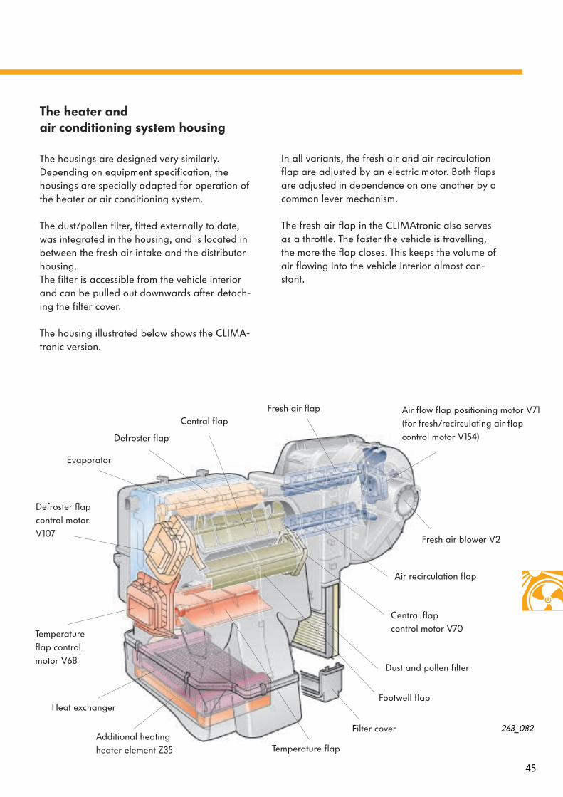
The heater and air conditioning system housing
The housings are designed very similarly. Depending on equipment specification, the housings are specially adapted for operation of the heater or air conditioning system.
The dust/pollen filter, fitted externally to date, was integrated in the housing, and is located in between the fresh air intake and the distributor housing.The filter is accessible from the vehicle interior and can be pulled out downwards after detach-ing the filter cover.
The housing illustrated below shows the CLIMA-tronic version.
In all variants, the fresh air and air recirculation flap are adjusted by an electric motor. Both flaps are adjusted in dependence on one another by a common lever mechanism.
The fresh air flap in the CLIMAtronic also serves as a throttle. The faster the vehicle is travelling, the more the flap closes. This keeps the volume of air flowing into the vehicle interior almost con-stant.
263_082
Air flow flap positioning motor V71 (for fresh/recirculating air flap control motor V154)
Fresh air blower V2
Air recirculation flap
Central flap control motor V70
Dust and pollen filter
Temperature flapAdditional heating heater element Z35
Defroster flap
Defroster flap control motor V107
Central flap Fresh air flap
Temperature flap control motor V68
Filter cover
Evaporator
Heat exchanger Footwell flap

46
The heater
In the heater, the temperature flap and the air distribution flaps are adjusted with the rotary knobs on the control panel. The heater is adjusted by flexible shafts, each of which is engaged in the control panel and the heater and air conditioning system housing.The shafts for the temperature flap and air distri-bution are not of equal length. To avoid confu-sion, the plug and socket connections of the shafts are colour-coded.
The flexible shafts have the following advan-tages over the Bowden cable:
– short routing with narrow curve radius– no length adjustment is needed
Heater, air conditioning system
The air recirculation mode can be switched on and off using the air recirculation button.
In diesel engine vehicles, an additional heating element is used in combination with the heat exchanger to warm up the vehicle interior quickly.
Before you decouple the shafts from the control panel or from the heater and air conditioning system housing, please follow the inspection and installation instructions given in the Workshop Manual.
263_140
263_063
263_153Flexible shaft
Footwell flap
Temperature flap
Central flap
Flexible shaft coupling

47
Microswitches for the additional heating element and defroster
The microswitches are located in the control panel housing. The microswitch is pressed against the electrically-conductive contact sur-face by a cam on the rotary knobs for tempera-ture selection or air distribution. The control electronics utilise the earth signal generated simultaneously as a criterion for activating the additional heating element "ON" function, or recirculating air mode automatic "OFF" when this is adjusted to Defrost mode.The air recirculation function can be activated by again pressing the air recirculation button in the Defrost position.Both microswitches work according to the same principle.The mode of operation of the microswitch is des-cribed on the following pages using the additio-nal heating element "ON/OFF" function as an example.
Contact open
The contact is open when the rotary knob is in the operating range ´Cooling´ and heating output is up to approx. 90%.This breaks the signal earth contact to the engine control unit.
The additional heater heating element does not cut in within this operating range.
Contact closed
The contact switch is closed in the operating range Cooling and between 90% and 100% heating output. When the contact switch is in this state, the earth signal is present at the engine control unit. If all these switch-on conditions are met, the addi-tional heating element switches on.
263_063
Contact surfaces/micro- switch for additional heating heater element
Contact surfaces/ microswitch for defroster
Rotary knobair distribution
Rotary knobtemperature selection
263_069
Microswitch
Contact surface
263_128
263_151
Cam

48
Additional heating element Z35
Heating output control
Approximately 10 seconds after the engine is started, the diesel direct injection system control unit enables the additional heating element. This ensures that the engine runs properly straight away.
Heater, air conditioning system
263_065
Switch-on conditions
Rotary knob fortemperature selection
Microswitch for additional heating element
Diesel direct injection system control unit J248
The control unit checks the following signals as switch-on conditions
Additional heating element Z35
If all these switch-on conditions are met, the additional heating element is switched on.
Engine speed higher than 450 rpm
3-phase AC alternator load factor not higher than 50% (terminal DF)
Battery voltage greater than 11 V
Coolant temperatureless than 80oC
Position of rotary knob: between 90% and 100% heating output
Contact switch opened 90% heating output and higher
If the rotary knob for interior temperature is posi-tioned to 90 -100% heating output and higher, the additional heating element switches on under certain conditions.
49
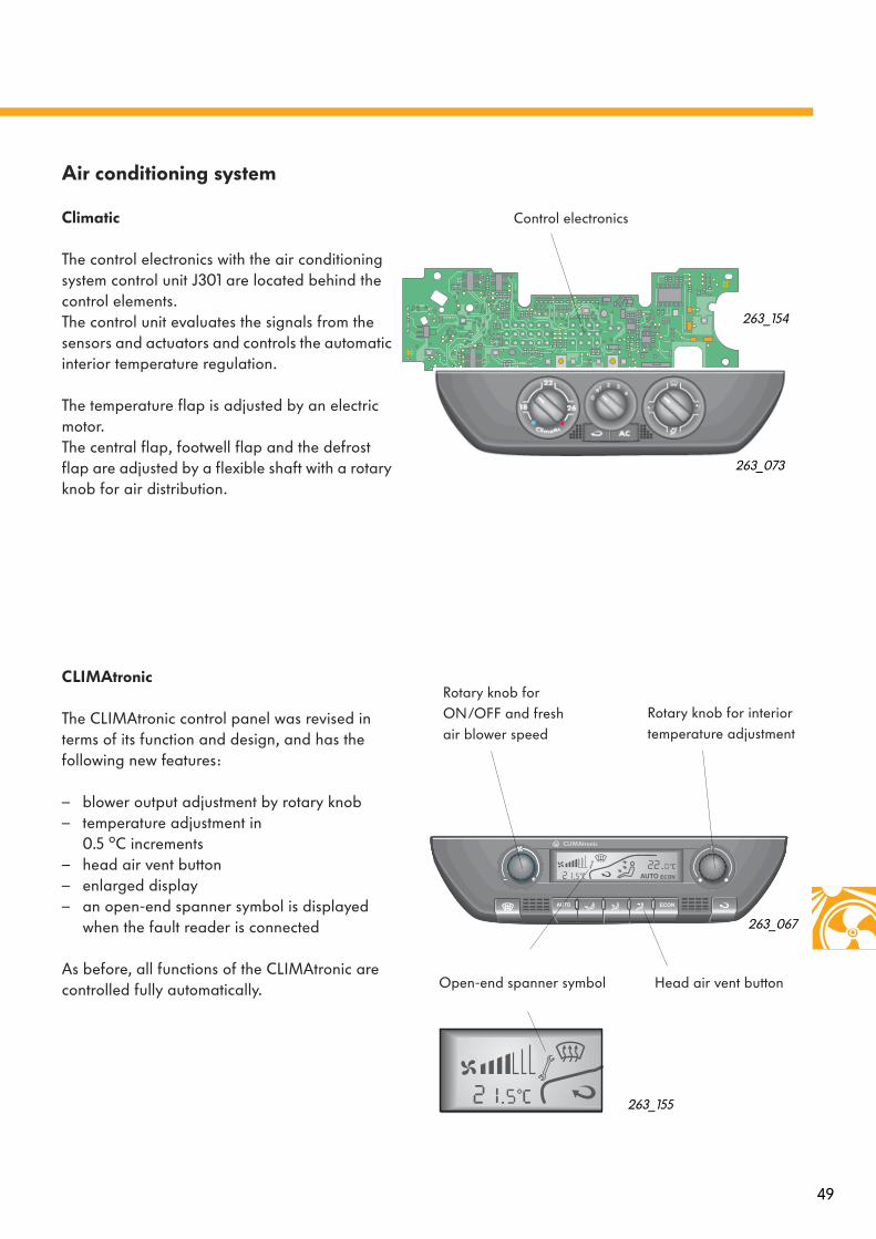
Air conditioning system
Climatic
The control electronics with the air conditioning system control unit J301 are located behind the control elements.The control unit evaluates the signals from the sensors and actuators and controls the automatic interior temperature regulation.
The temperature flap is adjusted by an electric motor. The central flap, footwell flap and the defrost flap are adjusted by a flexible shaft with a rotary knob for air distribution.
CLIMAtronic
The CLIMAtronic control panel was revised in terms of its function and design, and has the following new features:
– blower output adjustment by rotary knob– temperature adjustment in
0.5 oC increments– head air vent button– enlarged display– an open-end spanner symbol is displayed
when the fault reader is connected
As before, all functions of the CLIMAtronic are controlled fully automatically.
263_073
263_067
Rotary knob for ON/OFF and fresh air blower speed
Rotary knob for interior temperature adjustment
Head air vent buttonOpen-end spanner symbol
263_154
Control electronics
263_155

50
The variable swash plate inclination defines the working volume, and therefore the refrigeration capacity.
The compressor continues to run via the V-belt drive when the air conditioning system is switched off. The delivery volume of the refriger-ant is set to less than 2%.
Externally regulated compressor
Heater, air conditioning system
The compressor basically operates according to the drive plate principle. The design features which distinguish this compressor from the internally-regulated compressor are as follows:
– one-sided drive plate compressor with 6 lifting pistons– variable cubic capacity for adaptation to refrigerating demand – hollow pistons– pulley drive with integrated overload protection and no magnetic clutch– external compressor regulating valve N280 for control of the pressure conditions inside the
compressor
Function
The CLIMAtronic control unit J255 or the Climatic J301 activates the compressor regulating valve N280 in continuously variable mode.The pressure conditions on the low pressure side are adjusted via a control voltage depending on the following parameters:desired temperature setting, exterior and interior temperature, evaporator temperature and refri-gerant pressure in the refrigerant circuit.
Belt pulley with integratedoverload protection
Compressor regu-lating valve N280
Connection for CLIMAtronic control unit J255/Climatic control unit J301
263_066
Swash plateDrive plate
Shaped rubber element
Lifting piston

51
Overload protection
Compressor in operation
The ribbed belt pulley and the drive plate are positively connected by a shaped rubber ele-ment.
When the compressor is functional, the two pla-tes rotate in unison.
Compressor blocked
If the compressor becomes damaged internally, the drive gears may block. The drive plate is also brought to a halt.This increases considerably the transmission forces between the belt pulley and the drive plate. The belt pulley pushes the shaped rubber element towards the blocked drive plate in the direction of rotation.
The outside parts of the rubber element are sheared off, and the belt pulley and drive plate are disconnected. The belt pulley continues to rotate unobstructed. This prevents the V-belt and the engine from damage.
263_077
263_076
Shaped rubber element
Shaped rubber element
Blocked drive plate
Belt pulley
Sheared off material
Input shaftcompressor
Deformation due to blockage
Blocked
Sheared off material
Drive plate
Belt pulley
Shaped rubber element
Shaped rubber element

52
Evaporator control circuit
When the CLIMAtronic/Climatic is switched on, the cooling requirements are determined and adjusted on the basis of the temperature setting and various influencing factors.The components described on the following pages form a closed control loop and facilitate needs-orientated temperature control.
Compressor regulating valve N280
The external regulating valve is the interface between the low-pressure side and the high-pres-sure side of the compressor. It has a pressure-equalising function.
If increased cooling is required, the CLIMAtronic control unit J255 or the Climatic control unit J301 activates the regulating valve.
A actuating rod in the regulating valve is moved when a control voltage is applied to the solenoid regulating valve.
The period over which the control voltage is applied defines the adjustment range. The adjust-ment affects the cross section between the low-pressure and high-pressure sides in the valve. The high pressure increases with decreasing low pressure, and increases the drive plate inclination via the piston stroke.
Heater, air conditioning system
263_080
263_068
CLIMAtronic control unit J255
Compressor regulating valve N280

53
Evaporator vent temperature sender G263
Evaporator vent temperature sender G263 is built into the ventilation duct behind the evapo-rator and measures the vent temperature down-stream of the evaporator.
It performs two important tasks:
– It ensures that the air conditioning system cuts out at a temperature of approx. 0 oC downst-ream of the evaporator and that icing does not occur.
– In connection with the externally-regulated compressor, the vent temperature downst-ream of the evaporator can now be adjusted to between 0 oC and approx. 10 oC downst-ream of the evaporator.
Advantage:
It is no longer necessary for cold air to be "reheated" by the heat exchanger to achieve specific desired temperatures.
All in all, the evaporator control circuit helps to reduce energy consumption, and thus saves fuel.
263_139
Evaporator vent temperature senderG263
Cooled air
Intake air
Influencing factors:desired temperature inputambient temperatureinterior temperatureair conditioner vent temperaturesthe pressure level in the refrigerant circuit

54
Heater, air conditioning system
System overview - Climatic
263_003
Engine control unit J...
Radiator fan control unit J293
Radiator fan V7
Compressor regulating valve, air conditioning system N280
Temperature flap control motor V68
Fresh/recirculating air flap control motor V154
Ambient temperature sensor G17
Dash panel temperature sensor G56
Vent temperature sender, centre G191
Vent temperature sender, footwell G192
Evaporator vent temperature sender G263
High pressure sender G65
Air conditioning system control unit J301
Control unit with display in dash panel insert J285
Engi
ne C
AN
Con
veni
ence
CA
N
Data bus diagnosis inter-face J533 (integrated in vehicle electrical system control unit J519)
Colour codes/legend
= input signal= output signal= CAN data bus= bidirectional

55
A B
G65
V154V68
G92 G143
+15 +30
31
N280 75
V2
G191 G192 G263
M
M
N24
M
E9
G56 V42 K114 E159 K84 G267E35 L16
J301
M
Function diagram - Climatic
Components
E9 Fresh air blower switchE35 Air conditioner switchE159 Fresh air/air recirculating flap switchG56 Dash panel temperature sensor G65 High pressure senderG92 Control motor potentiometer for temperature flap G143 Control motor potentiometer, air recirculation flap G191 Vent temperature sender, centre G192 Vent temperature sender, footwellG263 Evaporator vent temperature sender G267 Rotary knob temperature selection potentiometerJ301 Air conditioning system control unitK84 Air conditioning system warning lampK114 Fresh air/air recirculation warning lampL16 Fresh air controls light bulb
N24 Fresh air blower with overheating fuse series resistor
N280 Compressor regulating valve, air conditioning system V2 Fresh air blowerV42 Temperature sensor blower V68 Temperature flap control motor V154 Fresh/recirculating air flap control motor
Code codes/Legend= input signal= output signal= positive= earth= CAN data bus
Auxiliary signalsA Fan speed 1B Fan speed 2
263_027
Convenience CAN

56
Extended service intervals
All engines used in the Polo Model Year 2002 feature extended service intervals (ESI).
– The service interval of petrol engine vehicles are 15,000 km/year to max. 30,000 km/2 years.
– The service interval of diesel engine vehicles are 15,000 km/year to max. 50,000 km/2 years.
To enable the two TDI engines with unit injector system to achieve service intervals up to 50,000 km, the following components of the engines with unit injector system were improved:
– The friction created by the drive of the unit injector on account of low surface pressure was reduced by enlarging the radii of the pressure pin (also refer to page 25 "New fea-tures of unit injector").
– By widening the connecting rod head, the contact surface of the piston pin was enlarged in relation to the small end.
– Piston cooling has been improved by a revi-sed cooling channel in the piston and modi-fied oil spray nozzles.
Service
Engines wwwwiiii tttthhhhoooouuuutttt extended service intervals should not be filled with long-life engine oil. Please pay attention to the oil stan-dards prescribed in the Workshop Manual.
Diesel engines with a unit injector system aaaannnndddd extended service intervals must be filled with long-life engine oil compliant with the VW 50601 standard.This oil can also be used for diesel engines with extended service intervals which do not have a unit injector system.
Detailed information about extended service intervals can be found in Self-Study Programme No. 224.
263_084

57
Service Interval Display
A new symbol and other display parameters have been added to the flexible Service Interval Display in the Polo.
Service advance warning
If a service is due shortly, a spanner symbol and the mileage to next service in "km" appears in the kilometre counter on the dash panel insert.
After 10 seconds, the display changes. A clock symbol and the number of days to the next ser-vice are then displayed.
On vehicles with an on-board computer, the fol-lowing message appears in the display on the dash panel insert:
Service in 2000 km or 40 days(Service in 2000 km oder 40 Tagen)
The driver’s personal driving style is taken into account to determine the service intervals besides the individual conditions of use and the quality of the engine oil.
263_136
263_137
263_138
SERVICEIN
2000 KModer
40 TAGEN

58
Service due
If a service is due, a gong signal sounds and a flashing spanner symbol appears in the kilome-tre counter on the dash panel insert for 20 seconds.
The following message appears on the display of the dash panel insert.
Service now(Service jetzt)
Service overdue
An overdue service is indicated by a minus sign before the displayed number of kilometres or days to the next service.
The following message appears on the display of the dash panel insert.
Service since 600 km or 8 days(Service seit 600 km oder 8 Tagen)
Service
SERVICEJETZT
263_145
263_146
263_147
263_148
SERVICESEIT
600 KModer
8 TAGEN
263_146

59
Special tools
Designation Tool Use
T10064/6A2-piece backing plate
For removing the wheel bearing
T10125Socket
For mounting the double hexa-gon nut to the outer CV joint the wheel hub
T30020Adjustment plate
For removing and installing 5-speed manual gearbox 02R
T30035Thust piece
For mounting the bonded rubber bush to the axle bracket

Service. 263
For internal use only © VOLKSWAGEN AG, Wolfsburg
All rights reserved. Technical specifications subject to change without notice.
140.2810.82.20 Technical status 09/01
❀ This paper is produced from
non-chlorine-bleached pulp.