SCARAB4 EXTENSION OF THE HIGH-FIDELITY RE-ENTRY BREAK …
12
SCARAB4 – EXTENSION OF THE HIGH-FIDELITY RE-ENTRY BREAK-UP SIMULATION SOFTWARE BASED ON NEW MEASUREMENT TYPES Ronny Kanzler (1) , Bent Fritsche (1) , Tobias Lips (1) , Andreas Breslau (1) , Adam Pagan (2) , Georg Herdrich (2) , Martin Spel (3) , Silvia Sanvido (4) , Stijn Lemmens (4) (1) HTG - Hyperschall Technologie Göttingen GmbH, Am Handweisergraben 13, 37120 Bovenden, Germany Email: [email protected], [email protected], [email protected] (2) Institute of Space Systems – University of Stuttgart, Pfaffenwaldring 29, 70569 Stuttgart, Germany Email: [email protected], [email protected] (3) R.Tech Engineering, Parc Technologique Delta Sud, 09340 Verniolle, France Email: [email protected] (4) ESA/European Space Operations Centre, Robert-Bosch-Straße 5, 64293 Darmstadt, Germany Email: [email protected], [email protected] ABSTRACT The high-fidelity re-entry break-up simulation software SCARAB (SpaceCraft Atmospheric Re-entry and Aerothermal Break-up) is currently being upgraded with new models for aerothermodynamics and material ablation. The capabilities of SCARAB are extended to improve the support of Design-for-Demise (D4D) methodology modelling and uncertainty quantification. A set of newly implemented features for the so-called measurement evaluation support (MES) provide the functionality to rebuild static flow conditions of wind tunnel experiments and Computational Fluid Dynamics (CFD) simulations and extend the SCARAB re-entry simulation with options for fixed attitude and reference trajectory input. The new models implemented are validated with recent data from wind tunnel experiments, re-entry observations and CFD, using the new MES capabilities. This paper provides an overview on the new SCARAB models and extended functionality. 1 INTRODUCTION According to ESA regulations, compliance with the ESA Space Debris Mitigation Compliance Verification Guidelines has to be demonstrated. For a first assessment, ESA’s DRAMA suite, including the so-called object- oriented re-entry code SESAM, has to be used to assess the casualty risk. In later stages, spacecraft oriented, i.e. high-fidelity, codes can be used for ground risk assessment [1]. SCARAB 3.1L [2], ESA’s current high-fidelity re-entry break-up simulation code, has been released a decade ago and the development of the SCARAB core routines reaches back 25 years. Back then, the models and approximations implemented were limited by computational power, as well as the limited data available on heating and ablation of different materials used in spacecraft construction. Recent experiments on different material samples in wind tunnel tests and other testing facilities provide significantly increased data of material behaviour, including ablation and oxidation, at high temperatures and under re-entry-like conditions. Newly developed, proof-of-concept models for re-entry simulations have been generated, e.g. for SAM [3] and through the support by computationally intensive methods, like CFD simulations, the development and validation of aerothermodynamic models in simplified (w.r.t. CFD) codes can be supported. During the recent years, several limitations of the current generation of re-entry simulation codes have become apparent, especially w.r.t. the modelling of Design-for- Demise techniques, the simulation of very large structures, where shock-shock and shock-structure interactions play a role, or re-entries from highly eccentric orbit, where radiative shock heating can be significant. DRAMA’s re-entry and risk analysis modules have been upgraded in the past years [4], implementing up-to-date methods and more sophisticated ablation models, combined with the option for Monte-Carlo simulations enabling the variation of a large set of parameters. However, the use of a spacecraft-oriented code is still an important step in the process of ground risk compliance verification and object-oriented re-entry codes need to be validated against data and simulation results generated with higher-fidelity tools, i.e. spacecraft-oriented simulation codes or CFD data. CFD simulations are very complex and need significant computational power. Thus, they are not applicable for the simulation of heating and break-up for a whole spacecraft. Considering the recent advances w.r.t. re-entry related experiments, observations and models, an upgrade of the current Proc. 8th European Conference on Space Debris (virtual), Darmstadt, Germany, 20–23 April 2021, published by the ESA Space Debris Office Ed. T. Flohrer, S. Lemmens & F. Schmitz, (http://conference.sdo.esoc.esa.int, May 2021)
Transcript of SCARAB4 EXTENSION OF THE HIGH-FIDELITY RE-ENTRY BREAK …

Leave footer empty – The Conference footer will be added to the first page of each paper.
SCARAB4 – EXTENSION OF THE HIGH-FIDELITY RE-ENTRY
BREAK-UP SIMULATION SOFTWARE BASED ON NEW
MEASUREMENT TYPES
Ronny Kanzler(1), Bent Fritsche(1), Tobias Lips(1), Andreas Breslau(1), Adam Pagan(2), Georg Herdrich(2),
Martin Spel(3), Silvia Sanvido(4), Stijn Lemmens(4)
(1) HTG - Hyperschall Technologie Göttingen GmbH, Am Handweisergraben 13, 37120 Bovenden, Germany
Email: [email protected], [email protected], [email protected] (2) Institute of Space Systems – University of Stuttgart, Pfaffenwaldring 29, 70569 Stuttgart, Germany
Email: [email protected], [email protected] (3) R.Tech Engineering, Parc Technologique Delta Sud, 09340 Verniolle, France
Email: [email protected] (4) ESA/European Space Operations Centre, Robert-Bosch-Straße 5, 64293 Darmstadt, Germany
Email: [email protected], [email protected]
ABSTRACT
The high-fidelity re-entry break-up simulation software
SCARAB (SpaceCraft Atmospheric Re-entry and
Aerothermal Break-up) is currently being upgraded with
new models for aerothermodynamics and material
ablation. The capabilities of SCARAB are extended to
improve the support of Design-for-Demise (D4D)
methodology modelling and uncertainty quantification.
A set of newly implemented features for the so-called
measurement evaluation support (MES) provide the
functionality to rebuild static flow conditions of wind
tunnel experiments and Computational Fluid Dynamics
(CFD) simulations and extend the SCARAB re-entry
simulation with options for fixed attitude and reference
trajectory input.
The new models implemented are validated with recent
data from wind tunnel experiments, re-entry observations
and CFD, using the new MES capabilities.
This paper provides an overview on the new SCARAB
models and extended functionality.
1 INTRODUCTION
According to ESA regulations, compliance with the ESA
Space Debris Mitigation Compliance Verification
Guidelines has to be demonstrated. For a first assessment,
ESA’s DRAMA suite, including the so-called object-
oriented re-entry code SESAM, has to be used to assess
the casualty risk. In later stages, spacecraft oriented, i.e.
high-fidelity, codes can be used for ground risk
assessment [1].
SCARAB 3.1L [2], ESA’s current high-fidelity re-entry
break-up simulation code, has been released a decade ago
and the development of the SCARAB core routines
reaches back 25 years. Back then, the models and
approximations implemented were limited by
computational power, as well as the limited data available
on heating and ablation of different materials used in
spacecraft construction.
Recent experiments on different material samples in
wind tunnel tests and other testing facilities provide
significantly increased data of material behaviour,
including ablation and oxidation, at high temperatures
and under re-entry-like conditions. Newly developed,
proof-of-concept models for re-entry simulations have
been generated, e.g. for SAM [3] and through the support
by computationally intensive methods, like CFD
simulations, the development and validation of
aerothermodynamic models in simplified (w.r.t. CFD)
codes can be supported.
During the recent years, several limitations of the current
generation of re-entry simulation codes have become
apparent, especially w.r.t. the modelling of Design-for-
Demise techniques, the simulation of very large
structures, where shock-shock and shock-structure
interactions play a role, or re-entries from highly
eccentric orbit, where radiative shock heating can be
significant.
DRAMA’s re-entry and risk analysis modules have been
upgraded in the past years [4], implementing up-to-date
methods and more sophisticated ablation models,
combined with the option for Monte-Carlo simulations
enabling the variation of a large set of parameters.
However, the use of a spacecraft-oriented code is still an
important step in the process of ground risk compliance
verification and object-oriented re-entry codes need to be
validated against data and simulation results generated
with higher-fidelity tools, i.e. spacecraft-oriented
simulation codes or CFD data. CFD simulations are very
complex and need significant computational power.
Thus, they are not applicable for the simulation of heating
and break-up for a whole spacecraft. Considering the
recent advances w.r.t. re-entry related experiments,
observations and models, an upgrade of the current
Proc. 8th European Conference on Space Debris (virtual), Darmstadt, Germany, 20–23 April 2021, published by the ESA Space Debris Office
Ed. T. Flohrer, S. Lemmens & F. Schmitz, (http://conference.sdo.esoc.esa.int, May 2021)
Leave footer empty – The Conference footer will be added to the first page of each paper.
spacecraft-oriented ESA code, i.e. SCARAB, is
inevitable.
The objective of the activity is to upgrade and extend the
current SCARAB (3.1L) to improve the calculation of the
re-entry casualty risk, considering recent data and results
obtained from CFD simulations, re-entry observations
and experimental testing on materials and material
response under re-entry conditions.
2 AEROTHERMODYNAMICS MODEL
The heating mechanisms considered in the
aerothermodynamics (ATD) model of SCARAB are
Convective heating
Radiative shock heating
Shock-boundary impingement on large objects
Internal radiative heat exchange
Internal conduction between parts (not
discussed here)
2.1 Convective shock heating
Convective heating is the standard heating mechanism
considered in all re-entry codes. In SCARAB 3.1L a local
flow inclination method was used in all flow regimes
(free-molecular to continuum). With the new approach, a
non-local method is used for the continuum regime, while
keeping the appropriate local approach for the free-
molecular regime. In the transitional regime still a
bridging method is used, hence keeping the approach
near-local in the free-molecular regime and non-local in
the near-continuum regime.
The convective heating formulas are based on the
boundary layer equations, which are considered as a
compromise between a comprehensive, but not
computationally affordable (e.g. Navier-Stokes) and a
too simplistic approach like the pure local inclination
method. Key parameters of the new method are the
effective radius of curvature, which scales the order of
magnitude of the heat flux, and the streamline length,
which determines the local heat flux distribution. In
SCARAB the surface of a modelled satellite is built of
many small triangular panels. For each panel the
streamline is traced upstream, based on the directions of
the incoming free stream and the local surface direction
(Figure 1), until a stagnation point is found. In this way
the streamline length is determined. At the stagnation
point the local radius of curvature is determined by the
variation of the panel normal directions around this point.
Special considerations are taken for the case that the
geometry at the stagnation point is flat or concave.
Figure 1: Streamline tracing by backward marching
2.2 Radiative shock heating
SCARAB was originally developed for the examination
of re-entries from Earth orbit. It was later extended to
Martian entries. It was not designed for super-orbital-
velocity entries (above 8 km/s in Earth orbit), which may
occur after a planetary mission nor for a return from a
highly eccentric orbit. In such cases the thermal radiation
of the shock in front of the entering spacecraft to the
spacecraft can become significant and was therefore
considered in the new version. The Brandis-Johnston
model [5] is now implemented to compute the stagnation
point and lateral heat flux distribution.
2.3 Shock boundary impingement on large
objects
Re-entry codes are in general developed for relatively
simple-shaped objects. Extended structures were
considered in recent code updates e.g. of DRAMA and
SAM in a heuristic manner. In SCARAB it is possible to
construct and consider the interaction between the
stagnation-region-induced shocks and the structure
downstream with a local approach. The shock wave
shape is computed by using the blast wave analogy. The
computed shock wave intercepts the structure in certain
regions, which can be localized by the software
automatically. The missing information about the
enhanced heating at intercept was derived from
numerical experiments performed by IRS Stuttgart [6].
This database is undergoing upgrades, e.g. by evaluating
the results of the R.Tech CFD SSI test case.
2.4 Internal radiative heat exchange
Besides of the external heating mechanisms there was
one internal heating mechanism not considered so far in
SCARAB yet, namely the heat re-radiation. While it was
already coded in early times (i.e. 20 years ago) it was not
actively used due to its demanding computation
requirements. During the last 20 years the computing
power has increased considerably, but according to test
calculations, the inclusion of re-radiation does not appear
Leave footer empty – The Conference footer will be added to the first page of each paper.
out of reach, but is still demanding. The main effect of
the re-radiation is that it cools the hot regions and warms
the cold regions which in turn effectively delays the
fragmentation process. This effect is going to be
examined in test calculations.
2.5 CFD support for ATD model validation
To support the validation of the new SCARAB ATD
model and supplement available CFD data (which is
limited to simple shapes), a set of CFD computations has
been performed by R.Tech, using the MISTRAL CFD
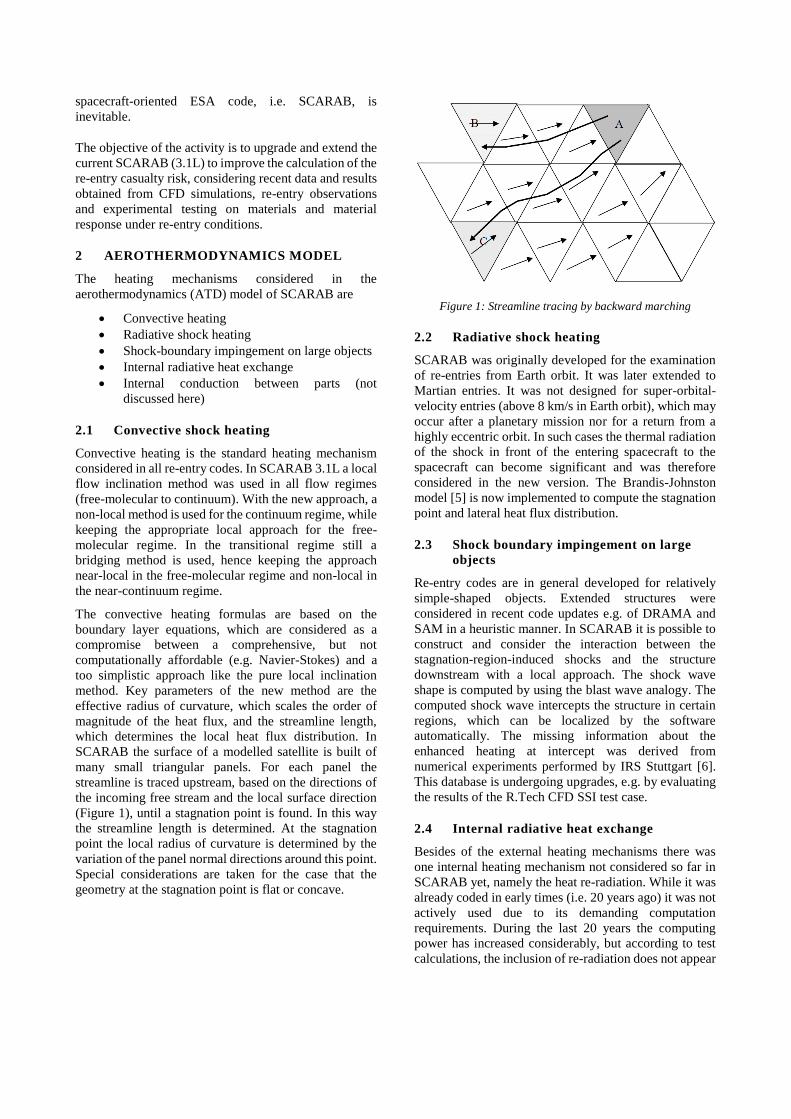
flow solver. A total of four geometries have been
simulated for different angles of attack, to provide
averaged heat flux and pressure distributions. The
geometries include a cylinder (Figure 2), a hollow half-
sphere (Figure 3), a simplified satellite shape (Figure 4)
and a shock-shock-interaction (SSI) case (Figure 5). The
validation matrix w.r.t. specific phenomena simulated by
the SCARAB ATD model is shown in Tab. 1.
Cylinder
Hollow
half-sphere Satellite SSI
Local heating
effects, off-
stagnation point
& edge heating
X X X X
Concave shapes X
Shock boundary
impingement X X
Tab. 1: Validation matrix: SCARAB4 ATD model phenomena
and CFD cases simulated by R.Tech
Figure 2: R.Tech CFD: Cylinder mesh
Figure 3: R.Tech CFD: Hollow half-sphere mesh
Figure 4: R.Tech CFD: Satellite mesh
Figure 5: R.Tech CFD: SSI mesh
3 MATERIAL ABLATION MODEL
The Advanced Demise and Ablation Model (ADAM) [7]
was motivated and described as a set of algorithms
designed to assess the thermal and ablative response of
different materials subjected to high-enthalpy air flows
relevant to destructive atmospheric entries. ADAM is
being developed specifically for integration with
SCARAB, with the intent to improve the fidelity of the
ground risk predictions. The proposed methodology
adapts the existing finite difference scheme and overall
architecture of the material ablation model of SCARAB
and expands upon it, incorporating a larger number of

Leave footer empty – The Conference footer will be added to the first page of each paper.
distinct material types and accounting for a wider range
of thermal response and ablation phenomena, which had
been identified and characterised in the course of various
past experimental activities, such as CHARDEM [8] and
CoDM [9].
The scope of ADAM encompasses the following aspects
relevant for ground risk prediction methodologies:
Material property dataset requirements
definition
Thermal surface interface definition and
handling for a given wall element, including
conductive and radiative interfaces as well as
aerothermodynamic interactions
Thermal response assessment on the surface and
within the volume of a given wall element
Ablation response assessment for a given wall
element
Definition of demise criteria for a given wall
element
The model in its current development state can simulate
the behaviour of six more or less distinct material types,
including metals, SiC-based ceramics, CFRP composites,
and chemically resilient materials affected by melt but
not oxidation such as oxide ceramics (“pure melters”).
Trade-offs with regards to the complexity and accuracy
of models describing the individual thermal response and
ablation phenomena were made in order to limit
computational costs while also attempting to fully exploit
the available input from the aerodynamics interface of
SCARAB.
The implementation in SCARAB covers five different
material types and corresponding physical effects as
listed in Tab. 2.
SCARAB
material type Examples Effects
Pure melter Glass, oxide
ceramics Catalysis, melting
Oxidising
melter Metals
Catalysis, melting,
surface oxidation
Oxidising
ceramic SiC, C/SiC
Catalysis, surface
oxidation
Ablator CFRP Surface oxidation/
combustion, pyrolysis
Combustor Graphite Combustion
Tab. 2: Material type and phenomena matrix of the SCARAB4
ADAM implementation
4 DESIGN FOR DEMISE METHODOLOGY
MODELLING
A SCARAB geometry model is composed of numerous
compounds which consist of simple geometric
primitives, such as e.g. boxes, cylinders, spheres, tori or
triangular or polygonal plates. In the past, these could be
either physically connected or separated (via gaps) and
during a re-entry simulation, break-up would happen,
when melting occurs.
The SCARAB4 connectivity analysis checks for
touching or overlapping model objects (compounds or
primitives) and provides a lists of these interfaces (Figure
6). For each interface, the user can select between
connected (physical connection and thermal conduction),
touching (thermal conduction only) and separate (no
connection or thermal conduction). Connected interfaces
are similar to the old SCARAB model object connection,
but can now be combined with one or more of the
following break-up triggers
Altitude
Dynamic pressure
Temperature
Temperature for a specific duration
Any combination of these triggers is possible and the first
condition matched during the simulation will result in the
dissolution of the connection, i.e. switching the interface
type from connected to separate.
Figure 6: SCARAB4 model interface editor
When a model object has no connected interface to
another model object, it will separate, creating a break-
up in the simulation. Thus, for model objects with
multiple interfaces, all interfaces must fail to result in a
break-up.
The definition of these interfaces allow for a more precise
modelling of component connectivity, while the break-up

Leave footer empty – The Conference footer will be added to the first page of each paper.
triggers improve the modelling of D4D implementations,
e.g. for early break-up.
A potential future extension of this approach could be to
perform a combined thermo-mechanical analysis for
these interfaces based on pre-defined connection types,
like bolted, glued or welded with specific temperature
dependent mechanical strength.
5 INTEROPERABILITY WITH DRAMA3
If DRAMA3 is installed in the machine, the SCARAB
workflow can make use of DRAMA3 functionality, i.e.
for orbit propagation and ground risk assessment.
5.1 Ground risk analysis
After a re-entry break-up simulation is finished,
SCARAB automatically creates a ground fragment list in
XML format compatible to the re-entry risk analysis
module of DRAMA3, SERAM (Spacecraft Entry Risk
Analysis Module).
The ground risk analysis can then be performed as part of
the SCARAB simulation work flow, by calling SERAM.
In addition, the user can export the fragment list for use
in DRAMA3, e.g. to do a Monte-Carlo variation of the
ground fragment data or the risk scenario using the
corresponding DRAMA3 functionality.
5.2 Material data import
In SCARAB, material data and geometry model data are
stored in a PostgreSQL database. The material editor of
the SCARAB GUI has been extended with an interface
to import material data from XML format, based on the
format used by DRAMA3/ESTIMATE [10], to the
SCARAB material database. To provide all material
properties required by the SCARAB implementation of
ADAM and the SCARAB structural analysis, the XML
format was extended, based on the specific material type,
with entries for
Catalycity (virgin material and oxide)
Combustion properties
Material strength
Oxide layer and oxide generation properties,
including parameters for active and passive
oxidation
Thermal expansion
While DRAMA3 uses two distinct material types
CFRPMaterial and metalMaterial, the XML import for
SCARAB expects on of the following material types and
the corresponding material properties:
ablator
combustor
oxidisingCeramic
oxidisingMelter
pureMelter
5.3 Orbit propagation for escaping fragments
Highly eccentric re-entries can result in fragments
escaping the atmosphere for another orbit revolution or
even multiple ones, when the perigee is at high altitude
inside the atmosphere [11].
As SCARAB performs a 6DoF propagation, simulating
such additional orbit revolutions of possibly hundreds of
fragments can have a significant impact on simulation
run time. Thus, the standard approach used in SCARAB
is to abort the propagation for an escaping fragment at a
user defined altitude. In [11] DRAMA’s orbit propagator
OSCAR/FOCUS was used with a manual handover of
data between the tools, to allow a full re-entry break-up
simulation for every escaping fragment. In SCARAB4,
OSCAR/FOCUS is called automatically by SCARAB
when a fragment reaches the ‘upper altitude limit’. The
orbit state of the fragment is converted via CSTATE into
a DRAMA3/OSCAR input file and OSCAR is executed.
The target altitude for the OSCAR propagation is the re-
entry interface, where the propagated state is passed back
to SCARAB the re-entry simulation is continued for the
fragment.
6 OTHER NEW OR EXTENDED
FUNCTIONALITY
6.1 Cross-platform results visualisation
In recent years, a standalone visualisation tool, the so-
called SCViewer, has been provided to HTG customers
to inspect and visualise SCARAB simulation results.
This tool has been updated as well, now providing a
single window overview (see appendix, Figure 8) on the
simulation results on the
Fragment tree (including all fragments
generated during the SCARAB simulation)
Ground track of the selected fragment
Visualisation of the selected fragment with a
timeline for the demise and tumbling state, as
well as an optional a colour map overlay for
Heat flux
Pressure
Temperature
Wall thickness
Ground fragment summary, including impact
mass, velocity and position per fragment
The SCViewer also provides the option to generate
animations of a re-entry break-up simulation.
6.2 Mars environment
To comply with planetary protection regulations, it can
be necessary to simulate the heating of a probe or orbiter
during Mars entry. For such applications, SCARAB
provides support for Mars environment models, i.e. the

Leave footer empty – The Conference footer will be added to the first page of each paper.
MGS-85F2 gravity model and the MCD 4.3 and Mars-
GRAM 2010 atmosphere models. The implementations
were developed for SCARAB Mars [12], which was a
separate, standalone tool, and has been merged into
SCARAB4 to allow a more flexible selection of the
planetary environment and easy future extension, e.g.
with Venus environment models.
6.3 Uncertainty quantification
To enable uncertainty quantification, SCARAB4
provides the option for input parameter variation using a
Monte-Carlo approach. It is possible to vary the
Aerothermal heating (via global scaling factor)
Break-up trigger conditions
Initial orbit and attitude state
Material properties
The material property variations include temperature
independent properties, such as density or melting
temperature, as well as temperature dependent ones, like
emissivity, heat capacity or thermal conductivity.
In the case of a Monte-Carlo variation, the extended,
automatic SCARAB simulation report provides a
summary on the results of such simulation batches.
7 MEASUREMENT EVALUATION
SUPPORT (MES)
To support the rebuild of Plasma Wind Tunnel (PWT)
experiments and re-entry observations, as well as
providing a sophisticated way to validate (new) models
implemented in SCARAB, a set of specific features has
been implemented.
The major component of the MES is the SCARAB Wind
Tunnel Mode (WTM), which is based on an
experimental, standalone tool used in the SCARAB
simulations for CHARDEM [7]. The WTM (example
shown in Figure 7) uses and supports all new SCARAB4
models and functionality. The first iteration supports
static stream conditions, defined through
Free stream density
Free stream static temperature
Free stream velocity
Oxygen content
Re-entry break-up simulations provide the options to use
a reference trajectory and/or fixed attitude of the so-
called main fragment (*.1 fragments in the SCARAB
fragment tree; usually the fragment with the highest
mass). This allows to better rebuild re-entry observations
where information on trajectory and/or attitude state is
available.
For both run modes, re-entry and WTM simulations,
sensor points can be defined to monitor temperature and
pressure at specific points within the geometry model.
Optionally, a sensor radius can be defined, where the
values are averaged. The sensor point data allows to
evaluate the conditions at points of interest within an
object, e.g. to compare with thermocouple measurements
of PWT tests.
Figure 7: SCARAB4 Wind Tunnel Mode visualization example
– Rebuild of D4D Breadboarding test 17 [13]
8 VALIDATION APPROACH
The new models implemented are validated with a two-
fold approach using micro- and macro-measurement test
cases to check the small scale behaviour, as well as the
overall break-up and demise during atmospheric re-entry.
For both types of validation cases, functionality of the
MES is used.
8.1 Micro-measurement validation cases
To validate the new ATD and material ablation models
implemented, CFD simulations and PWT experiments
are rebuilt using the SCARAB4 WTM. These validation
cases include
Aerothermodynamics model validation with
CFD comparisons
Material ablation model validation with IRS
PWT measurements
Complex wind tunnel rebuilds for combined
small scale ablation and break-up phenomena
comparison
In addition to the new CFD simulations performed by
R.Tech, CFD data from DLR [14] and ESA [15] is
available for simple shapes, i.e. sphere, cube, cone, flat
box/plate.

Leave footer empty – The Conference footer will be added to the first page of each paper.
The implementation of ADAM is validated by rebuilding
specific PWT experiments performed at IRS on a set of
different materials, including A316, AA7075, CFRP,
SSiC and PCW (insulator material), for both destructive
and non-destructive tests.
After independent validation of both models, complex
PWT test geometries are rebuild for three experiments, to
make a transition from small scale heating and ablation
simulation to demise and break-up of multi-material
geometries:
D4D Breadboarding tests 17, 18 and 21 (two
aluminium honeycomb sandwich panels with
aluminium or CFRP face sheets; connected by
cleats and spool/surface inserts) [13]
SECRET BBU mock-up (Test No. 8) [16]
SECRET battery mock-up (Test No. 13) [16]
With these complex PWT rebuilds, the goal is to try to
reproduce the demise observed in the experiment and the
heating measured by the thermocouples throughout the
samples. It has to be noted however, that these rebuilds
are limited to thermal effects, since the application of
forces and mechanical stresses is currently not included
in the SCARAB WTM simulations.
8.2 Macro-measurement validation cases
As a final validation step, after the successful validation
of the small scale behaviour, the general demise and
break-up during atmospheric re-entry is validated and
compared to observational data for the following cases
ATV-1
Re-run of previous SCARAB simulation [17]
and comparison to observations and spectra
recorded.
ATV-3 + REBR Try to rebuild of specific events derived from
Re-Entry Break-up Recorder (REBR) [18].
WT1190F [19] and Hayabusa [20, 21]
Validation of the radiative shock heating model
and comparison to observation data.
PAM-D (Delta-II third stage)
Rebuild ground fragments found and validate
temperature range during re-entry, e.g. via
surface oxidation.
9 FIRST VALIDATION RESULTS
The validation of the models implemented is currently
on-going. The aerothermodynamic model was compared
with available CFD data from ESA, DLR, and R.Tech.
The ESA and DLR data were computed with the DLR
Tau code, the R.Tech data with the R.Tech Mistral code.
The following figures show sample results for a sphere, a
plate, a cone, a cylinder, and a hollow sphere.
Sphere
In Figure 9 (appendix) the heat flux on a 1m-diameter
sphere is shown as function of the axial distance to the
stagnation point. It is clearly visible that the new non-
local approach used in SCARAB4 better fits the ESA
CFD data than the local flow inclination method used in
SCARAB 3.1L.
Plate
Figure 10 (appendix) shows the heat fluxes on a 1x1x0.05
m plate at different angles of attack, with 0 degrees
indicating a perpendicular and 90 degrees a tangential
incident. Next to the sphere, a flat plate is THE reference
case for a boundary layer based approach. The agreement
between ESA CFD and SCARAB4 is good, except for
the tangential (90 degrees) case, where the heat flux
behind the tip is overestimated in SCARAB4. This can
be explained by an overexpansion around the corner of
the small but finite plate front face at this condition,
which is not considered in SCARAB4.
Cone
Figure 11 (appendix) shows the heat fluxes on a 1x1 m
LxD cone at different angles of attack, with 0 degrees
indicating the cone tip aligned to the flow. The agreement
is again good, confirming that the boundary layer based
approach is also applicable to axisymmetric geometries,
which is mathematically justified by the Mangler
transformation.
Cylinder
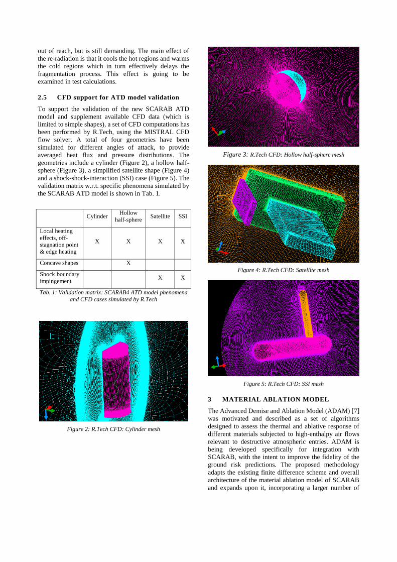
Figure 12 compares qualitatively the heat flux on a
cylinder at 45 degrees angle of attack. It shows that the
peak heating is qualitatively covered correctly by the new
approach. This is confirmed by a comparison of the
stagnation line heat fluxes shown in Figure 13. In
SCARAB 3.1L the heat flux depends only on the local
flow inclination and therefore shows no variation around
the exposed tip.
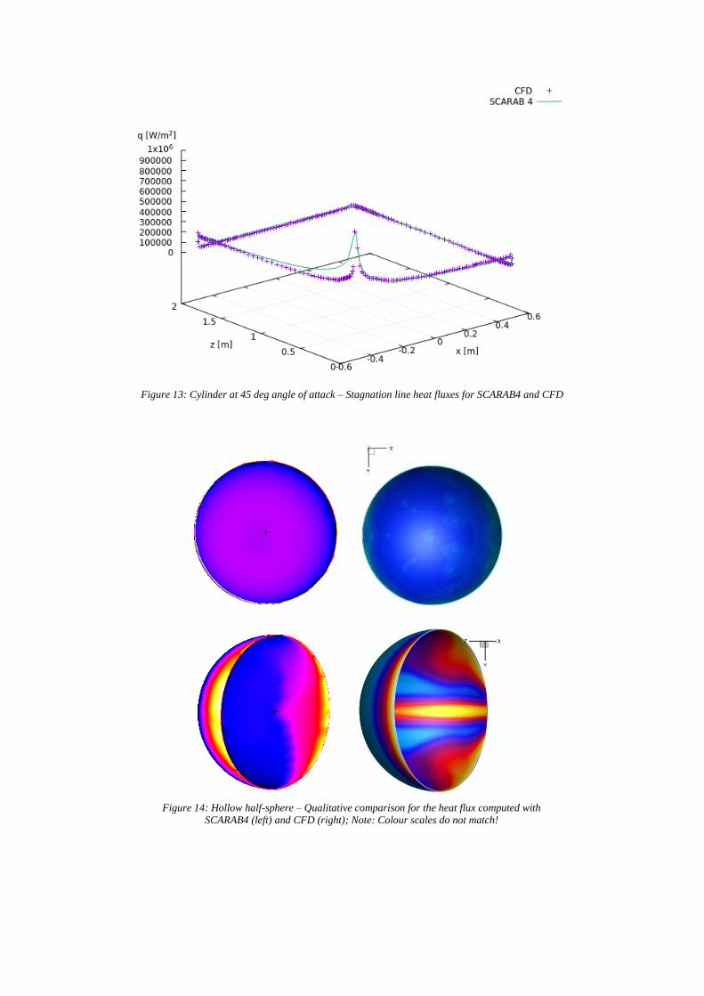
Hollow half-sphere
Figure 14 compares qualitatively the heat flux onto and
into a hollow sphere when exposed to the flow at zero
(flow head-on to the concave side) and at 45 degrees
angle of attack. The new ATD model considers the
concave form of the geometry, resulting in a quite
uniform heat flux distribution in the head-on case, in
accordance with the CFD result. At angle of attack the
flow structure inside the cavity is less pronounced in the
new SCARAB than in the CFD results. This can be
explained partially by the unsteady character of the flow
(emerging in the time-dependent CFD simulation, the
SCARAB approach is stationary) and, of course, by the
approximations used in the simplified approach, which
become especially critical when applied to of-design
configurations.

Leave footer empty – The Conference footer will be added to the first page of each paper.
10 SUMMARY
Based on recent data from wind tunnel tests, other
experiments and Computational Fluid Dynamics (CFD),
state-of-the-art models for material ablation and aero-
thermodynamics have been implemented into SCARAB.
Developed by the Institute of Space Systems (IRS) of the
University of Stuttgart, the new Advanced Demise and
Ablation Model (ADAM) extends the capabilities of
SCARAB to simulate the demise of five more or less
distinct material types, including metals, insulators,
ceramics, CFRP composites. The new aero-
thermodynamics model, developed by Hyperschall
Technologie Göttingen GmbH, includes new features
such as the calculation of local heating based on local
radius of curvature, flow stream length and geometry
conditions, shock impingement on large structures and
radiative shock heating. The validation of this model is
supported by CFD calculations performed by R.Tech
Engineering.
SCARAB4 allows to define break-up triggers at the
interface between geometric primitives or compounds,
improving the capabilities of Design-for-Demise
modelling and providing a more realistic modelling of
joints between components. New interfaces to ESA’s
DRAMA software enable SCARAB to quickly propagate
the orbit of escaping objects or fragments until the next
re-entry and calculate the ground risk using the recently
upgraded capabilities of DRAMA3. Similar to
DRAMA3, SCARAB now allows uncertainty
quantification using a Monte-Carlo like parameter
variation on simulation input, including material
properties.
The upgrade of SCARAB is accompanied by the
development of a new feature set for Measurement
Evaluation Support (MES), providing an additional run
mode, the 'Wind Tunnel Mode', to enable the simulation
of wind tunnel experiments, using pre-defined, static
flow conditions and allowing the user to define sensors
points inside the sample geometry to 'measure' the
physical properties at these positions. This allows to
validate the new models by re-building specific
experiments. The MES also extends the capabilities of re-
entry break-up simulations, allowing the user to perform
simulations along a pre-defined trajectory, to rebuild re-
entry events which can be compared to observations.
Using the MES functionality, the upgraded models are
currently validated with a set of micro- and macro-
measurements, including the rebuild of small scale
behaviour, as well as the general break-up and demise
process during atmospheric re-entry.
11 ACKNOWLEDGEMENT
The work performed for the Extension of the high-fidelity
re-entry break-up simulation software based on new
measurement types is funded by ESA under Contract No.
4000126069/18/D/SR.
12 REFERENCES
1. ESA Re-entry Safety WG (2017). ESA Re-entry
Safety Requirements, ESSB-ST-U-004.
2. Lips, T., Fritsche, B., Homeister, M., et al. (2007). Re-
entry Risk Assessment for Launchers – Development
of the new SCARAB 3.1L’, Proceedings of the Second
IAASS Conference, SP-645, ESA Communication
Production Office, ESTEC, Noordwijk, The
Netherlands.
3. Beck, J., Holbrough, I., Merrifield, J., Joiner, N.,
Bainbridge, S. (2017). Progress in hybrid
spacecraft/object oriented destructive re-entry
modelling using the SAM code, 7th European
Conference on Space Debris.
4. Kanzler, R., et al. (2017). Upgrade of DRAMA’s
Spacecraft Entry Survival Analysis Codes, 7th
European Conference on Space Debris, Darmstadt,
Germany.
5. Brandis, A. M., Johnston, C. O. (2014).
Characterization of stagnation-point heat flux for
earth entry, 45th AIAA Plasmadynamics and Lasers
Conference, Atlanta, GA, United States.
6. Zander, F., et al. (2017). Numerical Analysis of the
ISS Re-entry, 7th European Conference on Space
Debris, Darmstadt, Germany.
7. Pagan, A., et al. (2020). Improved Aerothermal
Material Demise Model for the Re-entry Break-up
Analysis Software SCARAB (Presentation),
Aerothermodynamics for Design for Demise (ATD³)
Workshop.
8. Schleutker, T., Esser, B., Gülhan, A. (2016).
Characterization of Demisable Materials
(CHARDEM) Final Report, Technical Report, DLR
9. Pagan, A., et al. (2015). Characterisation of Demisable
Materials through Plasma Wind Tunnel Testing, 8th
European Symposium on Aerothermodynamics for
Space Vehicles, Lisbon, Portugal.
10. Merrield, J. (2018). Characterisation of
Demisable Materials: Database Design and Final
Report, Technical Report Report No CR007_18, Fluid
Gravity Engineering Ltd.
11. Kanzler, R., et al. (2014). Re-entry of spacecraft
on highly eccentric orbits - Cluster-II, 65th
International Astronautical Congress, Toronto,
Canada

Leave footer empty – The Conference footer will be added to the first page of each paper.
12. Fritsche, B., Lips, T. (2014). Simulation Tool
for Breakup/Burnup Analysis of Mars Orbiters - Final
Report, SC-M_FR, Revision 1.0.0, HTG - Hyperschall
Technologie Göttingen GmbH
13. Fittock M., et al. (2018). Methodology and
results of demisability testing for state-of-the-art
structural joining technologies, Clean Space
Industrial Days 2018
14. Spel, M., Rivola, V., Plazolles, B. (2015). First
spacecraft demise workshop –test case description and
results, 8th European Symposium for the
Aerothermodynamics of Space Vehicles, Lisbon.
15. Van den Eynde, J., Lemmens, S. (2019). CFD
Computations of Orbital and Super-Orbital Re-entry
Heating on Primitive Shapes, International
Conference on Flight Vehicles, Aerothermodynamics
and Re-entry Missions and Engineering, Monopoli,
Italy
16. Beck, J., Holbrough, I., Schleutker, T. (2019).
Characterisation of Behaviour of Critical Elements in
Re-Entry Conditions: Final Report, PR00046/D26,
Issue 1, Belstead Research Ltd.
17. Lips, T., et al. (2011). Assessment of the ATV-
1 Re-entry Observation Campaign for Future Re-entry
Missions - Final Report, ATV/GSP1-FR, Revision
1.0.0, Hyperschall Technologie Göttingen.
18. Ailor, W. H., et al. (2013). Reentry Breakup
Recorder: Summary of data for HTV3 and ATV-3
Reentries and future directions, 6th European
Conference on Space Debris, Darmstadt, Germany.
19. Buzzoni, A., et al. (2017). The puzzling case of
the deep-space debris WT1190F: a test bed for
advanced SSA techniques, Stardust Final Conference:
Advances in Asteroids and Space Debris Engineering
and Science, ESA ESTEC, Noordwijk, The
Netherlands.
20. Shoemaker, M. A., et al. (2013). Trajectory
Estimation of the Hayabusa Spacecraft During
Atmospheric Disintegration, Journal of Spacecraft
and Rockets, Vol. 50, No. 2, March - April.
21. Cassell, A. M., et al. (2011). Hayabusa Re-
entry: Trajectory Analysis and Observation Mission
Design, 42nd AIAA Thermophysics Conference,
Honolulu, HI, United States.

Leave footer empty – The Conference footer will be added to the first page of each paper.
Appendix
Figure 8: SCViewer – SCARAB4 results visualisation mock-up with fragment list (left), ground track (top left), fragment
visualization with colour map overlay (top right), variable x-y plot (bottom left) and ground fragment summary (bottom right)
Figure 9: Heat flux comparison - Sphere: CFD, SCARAB3.1L and SCARAB4

Leave footer empty – The Conference footer will be added to the first page of each paper.
Figure 10: Heat flux comparison - Plate: CFD and SCARAB4
Figure 11: Heat flux comparison - Cone: CFD and SCARAB4
Figure 12: Cylinder at 45 deg angle of attack – Qualitative comparison for the heat flux computed with
SCARAB4 (left) and CFD (right); Note: Colour scales do not match!
[W/m²]
Leave footer empty – The Conference footer will be added to the first page of each paper.
Figure 13: Cylinder at 45 deg angle of attack – Stagnation line heat fluxes for SCARAB4 and CFD
Figure 14: Hollow half-sphere – Qualitative comparison for the heat flux computed with
SCARAB4 (left) and CFD (right); Note: Colour scales do not match!