ROADWAY DESIGN CRITERIA - Illinois Tollway
71
Roadway Design Criteria MARCH 2016 ILLINOIS STATE TOLL HIGHWAY AUTHORITY
Transcript of ROADWAY DESIGN CRITERIA - Illinois Tollway
Roadway Design Criteria
MARCH 2016
ILLINOIS STATE TOLL HIGHWAY AUTHORITY

ROADWAY DESIGN CRITERIA
Roadway Design Criteria dated March 2016 replaces the version issued March 2015. List of Major Revisions for March 2016: Criteria have been added for C-D Roadways throughout the document. Section 1. Introduction
Article 1.1 – Abbreviations & Acronyms. New Article. Article 1.2 – Definitions. New Article. Article 1.3 – Previously was Article 1.1. Article 1.4 – Previously was Article 1.2. Article 1.5 – Previously was Article 1.3. Criteria for Central Tri-State added. Revised Reagan Memorial criteria. Provided separate criteria for Preservation Projects. Article 1.6 – Previously was Article 1.4.
Section 2. Design Criteria
Article 2.2 – Revised criteria for curve closest to the crossroad for diamond/outer ramps. Article 2.4.1 – Reformatted Table. Most values did not change. Article 2.4.2 – Minimum distance between P.I.’s added (Footnote 11). Article 2.4.3 – Revised ramp formula and added Footnote 12. Article 2.4.7 – Added/revised criteria for ramps. Article 2.4.8 – Added/revised criteria for ramps. Article 2.5.4 – Maximum Algebraic Difference in Grade without Vertical Curve. New Article. Article 2.6.6 – Revised Table 2.6.6. Article 2.6.8 – Added Figure 2.6.8. Completely revised Article. Added guidance on sideslope hierarchy and transition length. Article 2.6.11 – Revised so that rumble strips are only installed on full width shoulders and both sides of C-D Roadways. Article 2.6.12 – Added reference for use of offset median barriers. Article 2.6.13 – Clarified desirable versus minimum for some items. Article 2.7.1 – Removed duplication from Article and added reference to Illinois Tollway Structure Design Manual for criteria. Article 2.7.2 – Provided cross referencing to Illinois Tollway Traffic Barrier Guidelines. Figure 3A – Design deviation no longer needed for 25 mph desgin speed when on the curve closest to the crossroad. Figure 3B – Added label for 0% cross slope. Percentage of SE runoff on the curve clarified. Figure 3C – Percentage of SE runoff on the curve clarified. Figures 4, 5 & 20 – Added 16’ dimension at painted nose of theoretical gore. Figure 6 & 7 – Added callout for location of painted nose of theoretical gore. Figure 9 – Added minimum taper rate.

ROADWAY DESIGN CRITERIA
ROADWAY DESIGN CRITERIA
March 2016 i Illinois Tollway
TABLE OF CONTENTS SECTION 1.0 INTRODUCTION ............................................................................................... 1 1.1 Abbreviations & Acronyms ............................................................................................... 1 1.2 Definitions ....................................................................................................................... 2 1.3 Purpose ........................................................................................................................... 5 1.4 Project Scope of Work ..................................................................................................... 6 1.5 General Requirements .................................................................................................... 7 1.6 Design Vehicle ................................................................................................................ 8 SECTION 2.0 DESIGN CRITERIA ........................................................................................... 9 2.1 Desirable Level of Service (LOS) ..................................................................................... 9 2.2 Design Speed .................................................................................................................. 9 2.3 Sight Distance ............................................................................................................... 10
2.3.1 Stopping Sight Distance ..................................................................................... 10 2.3.2 Decision Sight Distance ..................................................................................... 10 2.3.3 Glare Screen ...................................................................................................... 10
2.4 Horizontal Alignment ..................................................................................................... 11 2.4.1 Minimum Radii ................................................................................................. 11 2.4.2 Maximum Deflection Angle without Horizontal Curve ......................................... 12 2.4.3 Minimum Length of Curves ................................................................................ 12 2.4.4 Maximum Compound Curve Ratio ..................................................................... 12 2.4.5 Minimum Tangent between Curves .................................................................... 13 2.4.6 Maximum Superelevation ................................................................................... 13 2.4.7 Superelevation Rates ......................................................................................... 14 2.4.8 Superelevation Distribution ................................................................................ 15 2.4.9 Maximum Rollover (Algebraic difference in cross-slope) .................................... 16
2.5 Vertical Alignment ......................................................................................................... 17 2.5.1 Maximum Grades ............................................................................................... 17 2.5.2 Minimum Grades................................................................................................ 17 2.5.3 Minimum Length of Profile Tangent ................................................................... 17 2.5.4 Maximum Algebraic Difference in Grade without Vertical Curve ......................... 18 2.5.5 Design Controls for Crest Vertical Curves .......................................................... 18 2.5.6 Design Controls for Sag Vertical Curves ............................................................ 19
2.6 Cross-Sectional Elements ............................................................................................. 20 2.6.1 Pavement Width ................................................................................................ 20 2.6.2 Pavement Cross Slope ...................................................................................... 21 2.6.3 Paved Shoulder Width ...................................................................................... 21 2.6.4 Paved Shoulder Cross Slope ............................................................................. 22 2.6.5 Aggregate Shoulder Width ................................................................................. 22
ROADWAY DESIGN CRITERIA
March 2016 ii Illinois Tollway
2.6.6 Use of Gutters and Curbs .................................................................................. 23 2.6.7 Snow Storage Area ............................................................................................ 25 2.6.8 Sideslopes ......................................................................................................... 26 2.6.9 Ditch Bottom Width ............................................................................................ 27 2.6.10 Gore Area Cross Slopes .................................................................................... 28 2.6.11 Rumble Strips, Delineation Devices and Markings ............................................. 28 2.6.12 Emergency Turnarounds .................................................................................... 29 2.6.13 Crash Investigation Sites ................................................................................... 29
2.7 New Structures .............................................................................................................. 31 2.7.1 Shoulder Widths ................................................................................................ 31 2.7.2 Horizontal Clearances ........................................................................................ 32 2.7.3 Vertical Clearances ............................................................................................ 33 2.7.4 Deck Cross Slope .............................................................................................. 33
2.8 Toll Plazas ..................................................................................................................... 33 2.9 Roadside Safety ............................................................................................................ 33 2.10 Access Control .............................................................................................................. 33 2.11 Ramp Terminals ............................................................................................................ 33 2.12 Ramp/Roadway Convergence and Divergence Applications ......................................... 34 2.13 Stationing ...................................................................................................................... 34
Dual Stationing .............................................................................................................. 34 2.14 Right-of-Way Limits ....................................................................................................... 35
2.14.1 General .............................................................................................................. 35 2.14.2 Permanent Right-of-Way .................................................................................... 35 2.14.3 Permanent Easements....................................................................................... 35 2.14.4 Temporary Construction Easements .................................................................. 35
2.15 Design Policy for the Evaluation of Mainline Superelevation Deficiencies for Preservation and Rehabilitation Projects ....................................................................... 36 2.15.1 Evaluation .......................................................................................................... 36 2.15.2 Application of Policy ........................................................................................... 36
2.16 Design Policy for the Evaluation of Ramp Superelevation Deficiencies for Preservation and Rehabilitation Projects ....................................................................... 38 2.16.1 Evaluation .......................................................................................................... 38 2.16.2 Application of Policy ........................................................................................... 39
2.17 Guidelines for Replacement of Right-of-Way Fence along the Illinois Tollway System .......................................................................................................................... 41 2.17.1 Existing Fence ................................................................................................... 41 2.17.2 Forest Preserve ................................................................................................. 41 2.17.3 Farmland ........................................................................................................... 41 2.17.4 Relocation .......................................................................................................... 41
ROADWAY DESIGN CRITERIA
March 2016 iii Illinois Tollway
SECTION 3.0 FIGURES ........................................................................................................ 42
FIGURE 1 RESERVED
FIGURE 2 RESERVED
FIGURE 3A-3C RAMP SUPERELEVATION TRANSITIONS
FIGURE 3D-3G RESERVED
FIGURE 3H-3M MAINLINE SUPERELEVATION TRANSITIONS
FIGURE 4 TYPICAL ENTRANCE RAMP TERMINAL – PLAN
FIGURE 5 TYPICAL EXIT RAMP TERMINAL – PLAN
FIGURE 6 TYPICAL PARALLEL ENTRANCE RAMP TERMINAL – PLAN
FIGURE 7 TYPICAL PARALLEL EXIT RAMP TERMINAL – PLAN
FIGURE 8 TYPICAL TWO LANE ENTRANCE RAMP – PLAN
FIGURE 9 TYPICAL TWO LANE EXIT RAMP – PLAN
FIGURE 10 TYPICAL TWO LANE PARALLEL ENTRANCE RAMP – PLAN
FIGURE 11 TYPICAL TWO LANE PARALLEL EXIT RAMP – PLAN
FIGURE 12 RESERVED
FIGURE 13 RESERVED
FIGURE 14 RESERVED
FIGURE 15 RESERVED
FIGURE 16 RESERVED
FIGURE 17 RESERVED
FIGURE 18 RESERVED
FIGURE 19 TYPICAL PLAN DUAL STATIONING
FIGURE 20 TYPICAL EXIT RAMP TERMINAL WITH AUXILIARY LANE – PLAN
FIGURE 21A SAMPLE TYPICAL SECTION-MAINLINE
FIGURE 21B SAMPLE TYPICAL SECTION-RAMP
APPENDIX A Illinois Tollway, Interchange and Roadway Cost Sharing Policy
ROADWAY DESIGN CRITERIA
March 2016 - 1 - Illinois Tollway
SECTION 1.0 INTRODUCTION
1.1 Abbreviations & Acronyms AASHTO American Association of State Highway and Transportation Officials AASHTO GDHS AASHTO Geometric Design of Highways and Streets (Green Book) AASHTO RDG AASHTO Roadside Design Guide ADT Average Daily Traffic AET All Electronic Tolling B.S. Backslope B/C Benefit to Cost Ratio BWA Barrier Warrant Analysis CCTV Closed Circuit Television C-D Collector - Distributor CLSM Controlled Low Strength Material CM Construction Manager CMB Cable Median Barrier DCM Design Corridor Manager DMS Dynamic Message Sign DSE Design Section Engineer emax Maximum Superelevation EOP Edge of Pavement EOS Edge of Paved Shoulder EOTW Edge of Traveled Way F.S. Foreslope FHWA Federal Highway Administration GEC General Engineering Consultant IDOT Illinois Department of Transportation IDOT BDE IDOT Bureau of Design and Environment ISTHA Illinois State Toll Highway Authority (Illinois Tollway) ITS Intelligent Transportation System LRFD Load and Resistance Factor Design MASH Manual for Assessing Safety Hardware (AASHTO document) MOT Maintenance of Traffic M.P. Milepost MPH or mph Miles per Hour MSE Mechanically Stabilized Embankment MUTCD Manual of Uniform Traffic Control Devices MVDS Microwave Vehicle Detection System NAW Noise Abatement Wall NCHRP National Cooperative Highway Research Program P.C. Point of Curvature P.I. Point of Intersection P.T. Point of Tangency PBD Performance Based Design PM Project Manager ROW Right-of-Way RSAP Roadside Safety Analysis Program RWIS Roadway Weather Information System SE Superelevation TBG Traffic Barrier Guidelines
ROADWAY DESIGN CRITERIA
March 2016 - 2 - Illinois Tollway
TBT Traffic Barrier Terminal TL - # NCHRP or MASH Test Level (of the number specified) VEP Value Engineering Proposal WBPMs Web-Based Program Management system (currently using e-Builder)
1.2 Definitions AASHTO Roadside Design Guide. A guide that presents a synthesis of current information and operating practices related to roadside safety. It is developed and maintained by the AASHTO Subcommittee on Design, Technical Committee for Roadside Safety. Backslope. The parallel sideslope created by connecting the ditch bottom, shelf behind gutter, or back of gutter, upward and outward from the roadway, to the natural ground line. Barn-Roof Foreslope. Also called Variable Foreslope. Embankment section that uses a recoverable foreslope (typically 1:6 (V:H)) out to the limit of the defined clear zone and then uses a steeper slope down to the ditch bottom. This steeper slope shall be recoverable, or non-recoverable, but shall not be critical. Barrier Terminals. See Traffic Barrier Terminal. Barrier Warrant Analysis. The process in which a roadside obstacle is analyzed to determine whether or not it can be either removed, relocated, the severity reduced, or shielded. The term also refers to the collective document consisting of all of the locations within the contract limits, which contains all of the information needed for the analyses. Crashworthy. A characteristic of a roadside appurtenance that has been successfully crash tested for a certain test level in accordance with a national standard such as the NCHRP Report 350, “Recommended Procedures for the Safety Performance Evaluation of Highway Features” or AASHTO MASH and has been accepted by the FHWA. See Illinois Tollway TBG Section 8.0. Clear Zone. The clear zone is defined by the AASHTO RDG as “the unobstructed, traversable area provided beyond the edge of the through traveled way for the recovery of errant vehicles”. See Illinois Tollway TBG Article 5.3 for detailed definition and application of the clear zone by the Illinois Tollway. Critical Foreslope. Foreslope steeper than 1:3 (V:H) that cannot be safely traversed by a run-off-the-road vehicle. Depending on the encroachment conditions, a vehicle on a critical foreslope may overturn. Designer. The person (or consultant team) responsible for performing a design task for an Illinois Tollway project. Although this is typically the DSE, it can also include a person (or consultant team) hired by a Contractor to perform design as part of a VEP or part of a PBD. This document will use the term “Designer” which covers anyone performing design and will only use the term “DSE” when discussing tasks specific to the DSE. Downstream. The direction going with the flow of traffic.
ROADWAY DESIGN CRITERIA
March 2016 - 3 - Illinois Tollway
Edge of Pavement. The longitudinal joint between roadway pavement and shoulder pavement. In many locations, the outside lane of roadway pavement was built 1’ wider than it was striped. Along the existing Elgin O’Hare the outside lane was built 2’ wider than it is striped. Also, Lane 1 could be 14’ wide and striped at 12’. Edge of Shoulder. The edge of paved shoulder that is furthest from the edge of pavement. Edge of Traveled Way. The edge of roadway as viewed by the driver. Commonly, signified by the inside edge of a pavement marking edge line. Foreslope. The parallel sideslope created by connecting the outside edge of shoulder (usually aggregate shoulder) or the shelf behind the gutter, downward and outward from the roadway, to the ditch bottom or natural ground line. Gore. An area between a ramp and the mainline (or between two ramps), generally triangular in shape. For example, on a taper type exit ramp, the gore is from the painted nose on the upstream end to the gore nose on the downstream end. The painted nose is a point with no dimensional width occurring at the separation of roadways. The physical nose has some dimensional width that separates the two roadways. The gore nose (sometimes referred to as the back of gore) is the end of the paved area between the two roadways. The painted nose, physical gore and gore nose are shown on Figures 4 thru 7 for entrance and exit ramp terminals. Impact Attenuator. A protective device used to shield a rigid obstacle, such as a concrete barrier, a median barrier, or a bridge pier, by gradually decelerating the vehicle to a safe stop or by redirecting the vehicle away from the obstacle. Intersecting Slopes. See Transverse Slopes. Non-Recoverable Foreslope. Foreslope which can be safely traversed, but upon which an errant vehicle is unlikely to recover. The run-off-the-road vehicle will likely continue down to the toe of the slope. For most embankment heights, if a foreslope is between 1:3 (V:H) (inclusive) and 1:4 (V:H) (exclusive), it is considered a non-recoverable parallel slope provided that the slope is free of obstacles. Parallel Slopes. Foreslope and backslopes for which the toe/top runs approximately parallel to the roadway. Preferential Lane. A lane established on shoulder(s) for special uses per MUTCD, Section 3D.01 Recoverable Foreslope. Foreslope which can be safely traversed and upon which a motorist has a reasonable opportunity to regain control of the vehicle. Foreslopes 1:4 (V:H) and flatter are generally considered recoverable. Right-of-Way Line. The line separating Illinois Tollway owned property from another public agency or private property owner. In the case of a permanent easement, this line could be the access control line separating Illinois Tollway jurisdiction from another’s. Usually this line will have an access control fence adjacent to it.
ROADWAY DESIGN CRITERIA
March 2016 - 4 - Illinois Tollway
Roadside Safety Analysis Program. Computer software program developed for the NCHRP, Transportation Research Board, National Research Council to analyze the cost effectiveness of roadside alternatives as they relate to safety. This program is used by the Illinois Tollway in barrier warrant analyses for Level 3 warrants. Roadway. A Roadway consists of all lanes, auxiliary lanes and shoulders in one direction of travel. Shielding. The introduction of a barrier or crash cushion between the EOTW and an obstacle or area of concern to reduce the severity of impacts of errant vehicles. Shielded Slope. A sideslope (foreslope or backslope) that has guardrail or another barrier placed between the slope and the roadway. Shoulder Point. Point on a cross section where the slope of the aggregate shoulder (or shelf behind the gutter) meets the slope of the foreslope or backslope. (i.e. uppermost point on the foreslope, and the lowest point on the backslope). Sideslope. A foreslope or backslope adjacent to the roadway. The ratio is expressed as vertical to horizontal (V:H). See Foreslope and Backslope. Superelevation. Refers to the extra cross slope provided in curves to counteract centripetal force. Maximum SE refers to a design chart used to determine the cross slope given a speed and radius. The Illinois Tollway uses both 6% and 8% maximum SE. See Articles 2.4.1, 2.4.6 and 2.4.7. Tangent runout refers to the longitudinal distance to transition from normal crown to 0% cross slope. SE runoff refers to the longitudinal distance to transition from 0% cross slope to full SE. See Figures 3A thru 3C (ramps) and 3H thru 3M (mainline). Toe of Slope. The intersection of the foreslope with the natural ground line or ditch bottom, before any rounding is applied. Top of Slope. The intersection of the backslope with the natural ground line, before any rounding is applied. Traffic Barrier Terminal. The devices or systems attached to the approach and departing end of a guardrail installation used to anchor the installation and provide tension in the rail, and in some cases transition to other types of barriers (e.g., concrete barrier (single face and double face barrier), bridge parapets, retaining walls, etc.). See Illinois Tollway TBG Section 10.0. Transverse Slope. Also called intersecting slope. Slope for which the toe runs approximately perpendicular to the flow of traffic on the major roadway. Transverse slopes are typically formed by intersections between the mainline and entrances, median turnarounds, or side roads. They are also formed by a bridge cone or when transitioning from a ditch section to a non-ditch section. A transverse slope facing approaching traffic is considered to have a positive grade, while a transverse slope facing away from approaching traffic is considered to have a negative grade. Negative grade transverse slopes can be also be formed by a bridge cone on the downstream side of the bridge. The ratio is expressed as vertical to horizontal (V:H). Unshielded Slope. A sideslope (foreslope or backslope) that does not have guardrail or another barrier between the roadway and the sideslope. Because an errant vehicle would be
ROADWAY DESIGN CRITERIA
March 2016 - 5 - Illinois Tollway
expected on an unshielded slope, the sideslope within the clear zone limits shall be free of obstacles. Undefined Clear Zone. Where the sideslopes along the roadway are such that a definite clear zone distance is not determined based on AASHTO RDG Table 3-1 (foreslopes steeper than 1:4 (V:H); backslopes steeper than 1:3 (V:H)). Upstream. The direction going against the flow of traffic. Well Outside Clear Zone. A reasonable offset distance beyond the clear zone which, when applied to an obstacle’s location, would significantly reduce the probability of it being impacted by an errant vehicle. This is generally variable along the Illinois Tollway system. It is determined by the Designer, and takes several factors into account, such as ADT, number of lanes, slope configuration, and severity of obstacle. NOTE: This manual follows the traditional definitions for shall, should, and may. Shall is used to mean something that is required or mandatory, while should is used to mean something that is recommended, but not mandatory and may is used to mean something that is optional and carries no requirement or recommendation. 1.3 Purpose
These criteria are prepared as a guide to aid the Designer in the design of new and reconstructed facilities, and the preservation and rehabilitation of existing facilities for the Illinois Tollway. These criteria incorporate the most current appropriate standards for geometric design of the various roadway features. These standards are based on historic Illinois Tollway criteria, modified where necessary to reflect current state-of-the-art practices as set forth in the latest edition of the AASHTO GDHS. The latest editions of the AASHTO GDHS and IDOT BDE Manual shall be used for elements not covered by these criteria subject to the Illinois Tollway’s concurrence and/or approval.
The design of interchanges shall be subject to the requirements of the Illinois Tollway, Interchange and Roadway Cost Sharing Policy, current version. See Appendix A.
The Illinois Tollway’s intent is to provide the user with a facility that incorporates the highest feasible standards of design commensurate with existing conditions and cost constraints. Accordingly, minimum design standards included in this manual should only be used where all factors considered dictate their choice. Design parameters lower than the minimum design standards included in these criteria should comply with the AASHTO GDHS (or another nationally recognized agency or practice) and shall only be used if a Design Deviation has been approved by the Chief Engineer.
Currently applicable design criteria are set forth in the body of this document. In some cases, these criteria are divided into two categories. This is done because the original design of the existing systems was developed to two different design speeds. See Article 1.5.
Where references are made to AASHTO Tables or Figures they are intended to refer to the 2011 AASHTO GDHS, commonly referred to as the AASHTO Green Book.
ROADWAY DESIGN CRITERIA
March 2016 - 6 - Illinois Tollway
Where references are made to the Standard Drawings they are intended to refer to the latest edition of the Illinois Tollway Standard Drawings or IDOT Highway Standards.
1.4 Project Scope of Work
The project scope of work will reflect the basic intent of the improvement and will determine the applicable design criteria for the project.
The project scope of work for Illinois Tollway facility improvements are defined as preservation, rehabilitation, reconstruction, and new construction projects.
New construction consists of new Illinois Tollway facilities on new alignments and new ROW which extend Illinois Tollway facilities.
Reconstruction includes improvements within existing Illinois Tollway facility corridors, generally on existing alignments, which expand current Illinois Tollway facilities. Rehabilitation projects are structural or functional enhancements to the highway pavement, shoulders, and bridge decks to substantially improve the condition, safety, and ride quality in order to extend its service life. Rehabilitation projects include improvements to the structural integrity of the roadway pavement and may include but are not limited to intermittent patching, placing additional layers of surfacing, and subsequent milling and overlay of the pavement surface as well as repairing, overlaying and/or replacing existing bridge decks, bearings, superstructure, substructure, and expansion joints. Preservation projects are specific treatments to the highway pavement, shoulders, and bridge decks to preserve or enhance the condition, safety, and ride quality in order to maximize its service life. Preservation improvements may include but not limited to repairing current pavement and shoulder distress with minimal patching, crack sealing, and/or microsurfacing as well as sealing and/or repairing existing bridge decks, superstructure, substructure, and expansion joints. Preservation does not include pavement or deck overlays.
Specific items of rehabilitation work involving the correction of geometric deficiencies or deterioration will normally be specified in the scope of design work for each project. These items will reflect known conditions, deficiencies, and problem areas. Additionally, the Designer may be required to evaluate and make recommendations which may not have been apparent during the development of the project scope. It should be realized that the determination of the need for resurfacing may only be a part of the total rehabilitation necessary, and the Designer must also consider the need for additional work.
This document shows the criteria for Reconstruction and New Construction projects, and Preservation and Rehabilitation projects. For Rehabilitation projects, the Designer shall attempt to meet the Reconstruction and New Construction criteria if it is feasible to do so. If not feasible, then the Rehabilitation criteria should be followed. The term “Match Existing” shall be treated as the absolute minimum criteria. The Designer shall attempt to improve on the existing conditions where possible.
A Design Deviation is not required when “Desirable” criterion is not achieved.
ROADWAY DESIGN CRITERIA
March 2016 - 7 - Illinois Tollway
1.5 General Requirements (Rehabilitation, Reconstruction and New Construction Projects)
These are minimum criteria and should be maximized whenever feasible and within project scope.
Whenever reference is made to “60 mph” criteria shall apply to the following segments of the Illinois Tollway:
Tri-State: In Cook County, except M.P. 17.5 to 39.8, including the Edens Spur.
Jane Addams Memorial: East of the Tri-State to the Kennedy Expressway. Elgin-O’Hare All sections. West O’Hare Access All sections.
Whenever “70-mph” criteria are cited, they shall apply to all other segments of the system. Specifically:
Tri-State: In Lake County and M.P. 17.5 to 39.8 in Cook County. Jane Addams Memorial: All sections west of the Tri-State. Reagan Memorial: All sections. Veterans Memorial: All sections.
(Preservation Projects)
Whenever reference is made to “60 mph” criteria shall apply to the following segments of the Illinois Tollway:
Tri-State: In Cook County, except M.P. 17.5 to 39.8, including the Edens Spur.
Jane Addams Memorial: East of the Tri-State to the Kennedy Expressway. Reagan Memorial: East of Illinois Route 83. Elgin-O’Hare All sections. West O’Hare Access All sections.
Whenever “70-mph” criteria are cited, they shall apply to all other segments of the system. Specifically:
Tri-State: In Lake County and M.P. 17.5 to 39.8 in Cook County. Jane Addams Memorial: All sections west of the Tri-State. Reagan Memorial: All sections west of Illinois Route 83. Veterans Memorial: All sections.
ROADWAY DESIGN CRITERIA
March 2016 - 8 - Illinois Tollway
1.6 Design Vehicle (Rehabilitation, Reconstruction, and New Construction Projects) All major components of the roadway system, including intersections at ramp termini, shall be designed to accommodate the WB-67 design vehicle (2011 AASHTO, Section 2.1.1). (Preservation Projects) Match existing.
ROADWAY DESIGN CRITERIA
March 2016 - 9 - Illinois Tollway
SECTION 2.0 DESIGN CRITERIA
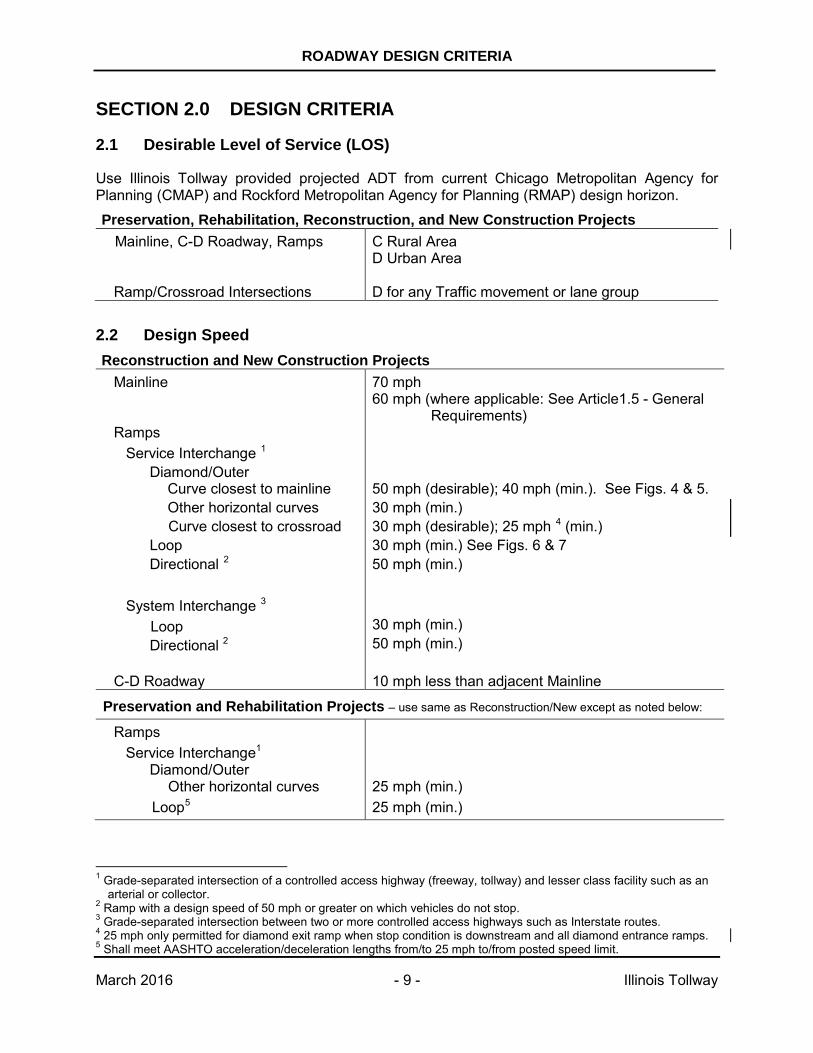
2.1 Desirable Level of Service (LOS)
Use Illinois Tollway provided projected ADT from current Chicago Metropolitan Agency for Planning (CMAP) and Rockford Metropolitan Agency for Planning (RMAP) design horizon.
Preservation, Rehabilitation, Reconstruction, and New Construction Projects Mainline, C-D Roadway, Ramps C Rural Area
D Urban Area
Ramp/Crossroad Intersections D for any Traffic movement or lane group
2.2 Design Speed Reconstruction and New Construction Projects
Mainline 70 mph 60 mph (where applicable: See Article1.5 - General
Requirements) Ramps
Service Interchange 1 Diamond/Outer Curve closest to mainline Other horizontal curves Curve closest to crossroad Loop Directional 2
System Interchange 3 Loop
Directional 2
50 mph (desirable); 40 mph (min.). See Figs. 4 & 5. 30 mph (min.) 30 mph (desirable); 25 mph 4 (min.) 30 mph (min.) See Figs. 6 & 7 50 mph (min.) 30 mph (min.) 50 mph (min.)
C-D Roadway 10 mph less than adjacent Mainline
Preservation and Rehabilitation Projects – use same as Reconstruction/New except as noted below:
Ramps Service Interchange1
Diamond/Outer Other horizontal curves
Loop5
25 mph (min.) 25 mph (min.)
1 Grade-separated intersection of a controlled access highway (freeway, tollway) and lesser class facility such as an
arterial or collector. 2 Ramp with a design speed of 50 mph or greater on which vehicles do not stop. 3 Grade-separated intersection between two or more controlled access highways such as Interstate routes. 4 25 mph only permitted for diamond exit ramp when stop condition is downstream and all diamond entrance ramps. 5 Shall meet AASHTO acceleration/deceleration lengths from/to 25 mph to/from posted speed limit.
ROADWAY DESIGN CRITERIA
March 2016 - 10 - Illinois Tollway
2.3 Sight Distance
2.3.1 Stopping Sight Distance Preservation, Rehabilitation, Reconstruction, and New Construction Projects
Mainline, Ramps, Preferential Lane (median), C-D Roadway
Use AASHTO Table 3-1 (for level roadway) and AASHTO Table 3-2 (on grade)
2.3.2 Decision Sight Distance (Preservation, Rehabilitation, Reconstruction, and New Construction Projects) At certain locations, sight distance greater than stopping sight distance is desirable to allow drivers time for decisions without making last minute erratic maneuvers (Reference Chapter III of AASHTO GDHS, for a thorough discussion of the derivation of decision sight distance.) Decision sight distance values are greater than stopping sight distance values because they give the driver an additional margin for error and afford sufficient length to maneuver at the same or reduced speed rather than to just stop. Provide decision sight distance at locations where there is high likelihood for driver error in information reception, decision making, or control actions. Examples include interchanges, major changes in cross section (such as toll plazas and drop lanes), and areas of concentrated demand where sources of information compete (such as roadway elements, traffic, traffic control devices, and oasis advertising signs). If site characteristics allow, locate these highway features where decision sight distance can be provided. If this is not practicable, use suitable traffic control devices and positive guidance to give advanced warning of the conditions. Use of decision sight distance is recommended at locations with complex driving decisions. Consideration for adjustment to these values may be necessary when determining decision sight distance for horizontal and vertical curves. 2.3.3 Glare Screen (Preservation, Rehabilitation, Reconstruction, and New Construction Projects)
Reference: IDOT BDE Manual Article 38-7.05, Glare Screens, for glare screen purpose, warrants, and design.
ROADWAY DESIGN CRITERIA
March 2016 - 11 - Illinois Tollway
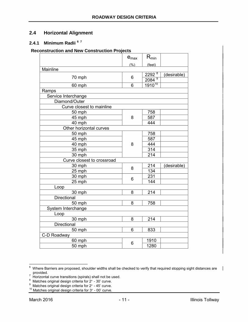
2.4 Horizontal Alignment
2.4.1 Minimum Radii 6 7 Reconstruction and New Construction Projects
emax
(%) Rmin
(feet)
Mainline
70 mph 6 2292 8 (desirable) 2084 9
60 mph 6 191010 Ramps Service Interchange Diamond/Outer Curve closest to mainline 50 mph
8 758
45 mph 587 40 mph 444 Other horizontal curves 50 mph
8
758 45 mph 587 40 mph 444 35 mph 314 30 mph 214 Curve closest to crossroad 30 mph 8 214 (desirable) 25 mph 134 30 mph 6 231 25 mph 144 Loop 30 mph 8 214 Directional 50 mph 8 758 System Interchange Loop 30 mph 8 214 Directional 50 mph 6 833 C-D Roadway 60 mph 6 1910 50 mph 1280
6 Where Barriers are proposed, shoulder widths shall be checked to verify that required stopping sight distances are
provided. 7 Horizontal curve transitions (spirals) shall not be used. 8 Matches original design criteria for 2° - 30’ curve. 9 Matches original design criteria for 2° - 45’ curve. 10 Matches original design criteria for 3° - 00’ curve.
ROADWAY DESIGN CRITERIA
March 2016 - 12 - Illinois Tollway
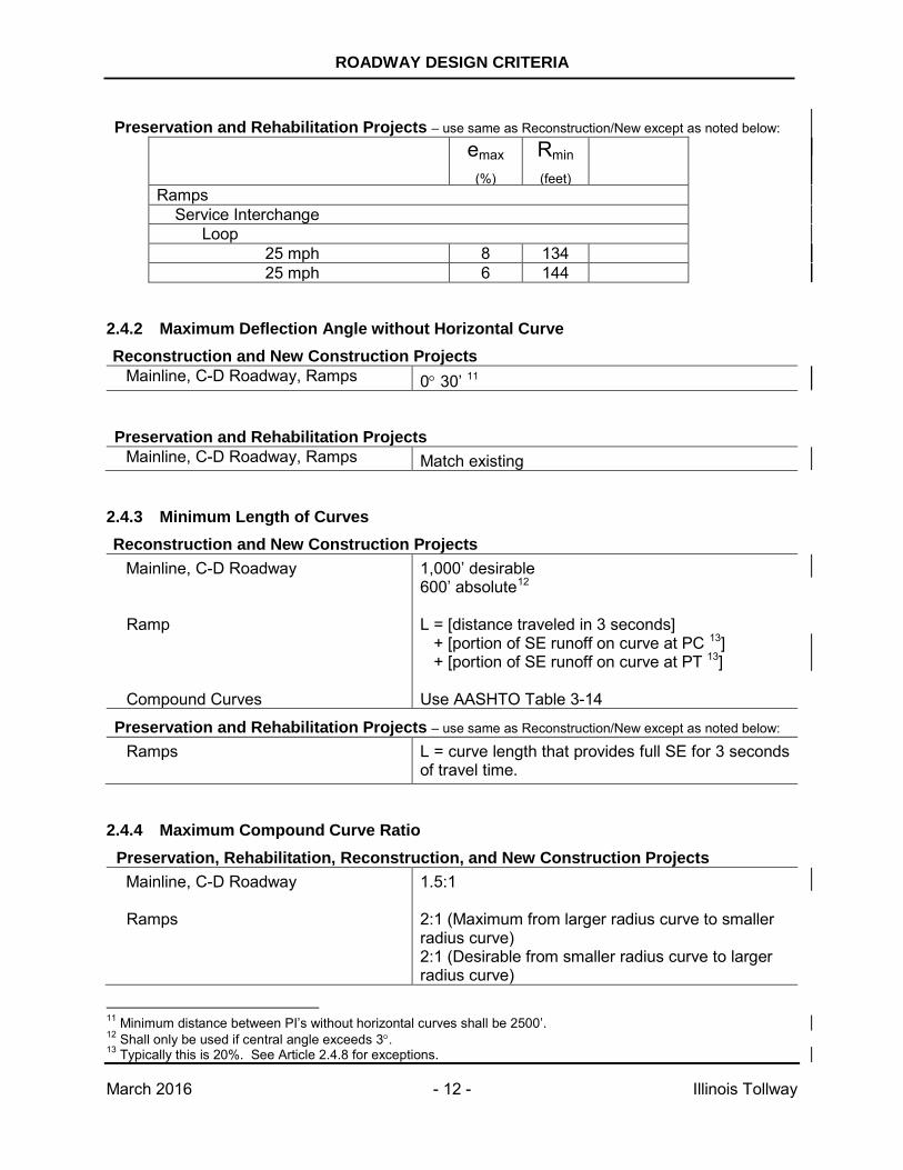
Preservation and Rehabilitation Projects – use same as Reconstruction/New except as noted below: emax
(%) Rmin
(feet)
Ramps Service Interchange Loop 25 mph 8 134 25 mph 6 144
2.4.2 Maximum Deflection Angle without Horizontal Curve Reconstruction and New Construction Projects
Mainline, C-D Roadway, Ramps 0° 30’ 11
Preservation and Rehabilitation Projects
Mainline, C-D Roadway, Ramps Match existing
2.4.3 Minimum Length of Curves Reconstruction and New Construction Projects
Mainline, C-D Roadway
1,000’ desirable 600’ absolute12
Ramp Compound Curves
L = [distance traveled in 3 seconds] + [portion of SE runoff on curve at PC 13] + [portion of SE runoff on curve at PT 13] Use AASHTO Table 3-14
Preservation and Rehabilitation Projects – use same as Reconstruction/New except as noted below: Ramps L = curve length that provides full SE for 3 seconds
of travel time.
2.4.4 Maximum Compound Curve Ratio Preservation, Rehabilitation, Reconstruction, and New Construction Projects
Mainline, C-D Roadway
1.5:1
Ramps
2:1 (Maximum from larger radius curve to smaller radius curve) 2:1 (Desirable from smaller radius curve to larger radius curve)
11 Minimum distance between PI’s without horizontal curves shall be 2500’. 12 Shall only be used if central angle exceeds 3°. 13 Typically this is 20%. See Article 2.4.8 for exceptions.
ROADWAY DESIGN CRITERIA
March 2016 - 13 - Illinois Tollway
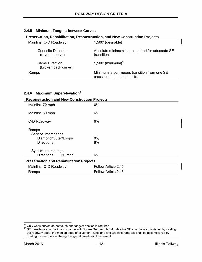
2.4.5 Minimum Tangent between Curves
Preservation, Rehabilitation, Reconstruction, and New Construction Projects Mainline, C-D Roadway 1,500’ (desirable)
Opposite Direction
(reverse curve) Absolute minimum is as required for adequate SE transition.
Same Direction (broken back curve)
1,500’ (minimum)14
Ramps Minimum is continuous transition from one SE cross slope to the opposite.
2.4.6 Maximum Superelevation15 Reconstruction and New Construction Projects
Mainline 70 mph 6%
Mainline 60 mph 6%
C-D Roadway Ramps
Service Interchange Diamond/Outer/Loops
Directional
System Interchange Directional 50 mph
6% 8% 8% 6%
Preservation and Rehabilitation Projects Mainline, C-D Roadway Ramps
Follow Article 2.15 Follow Article 2.16
14 Only when curves do not touch and tangent section is required. 15 SE transitions shall be in accordance with Figures 3A through 3M. Mainline SE shall be accomplished by rotating
the roadway about the median edge of pavement. One lane and two lane ramp SE shall be accomplished by rotating the ramp about the right edge (at baseline) of pavement.
ROADWAY DESIGN CRITERIA
March 2016 - 14 - Illinois Tollway
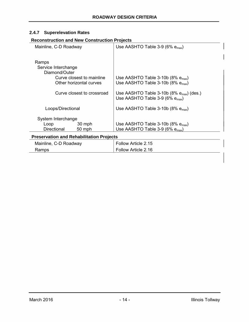
2.4.7 Superelevation Rates Reconstruction and New Construction Projects
Mainline, C-D Roadway Use AASHTO Table 3-9 (6% emax)
Ramps Service Interchange
Diamond/Outer Curve closest to mainline Other horizontal curves Curve closest to crossroad Loops/Directional
System Interchange Loop 30 mph
Directional 50 mph
Use AASHTO Table 3-10b (8% emax) Use AASHTO Table 3-10b (8% emax) Use AASHTO Table 3-10b (8% emax) (des.) Use AASHTO Table 3-9 (6% emax) Use AASHTO Table 3-10b (8% emax) Use AASHTO Table 3-10b (8% emax) Use AASHTO Table 3-9 (6% emax)
Preservation and Rehabilitation Projects Mainline, C-D Roadway Ramps
Follow Article 2.15 Follow Article 2.16
ROADWAY DESIGN CRITERIA
March 2016 - 15 - Illinois Tollway
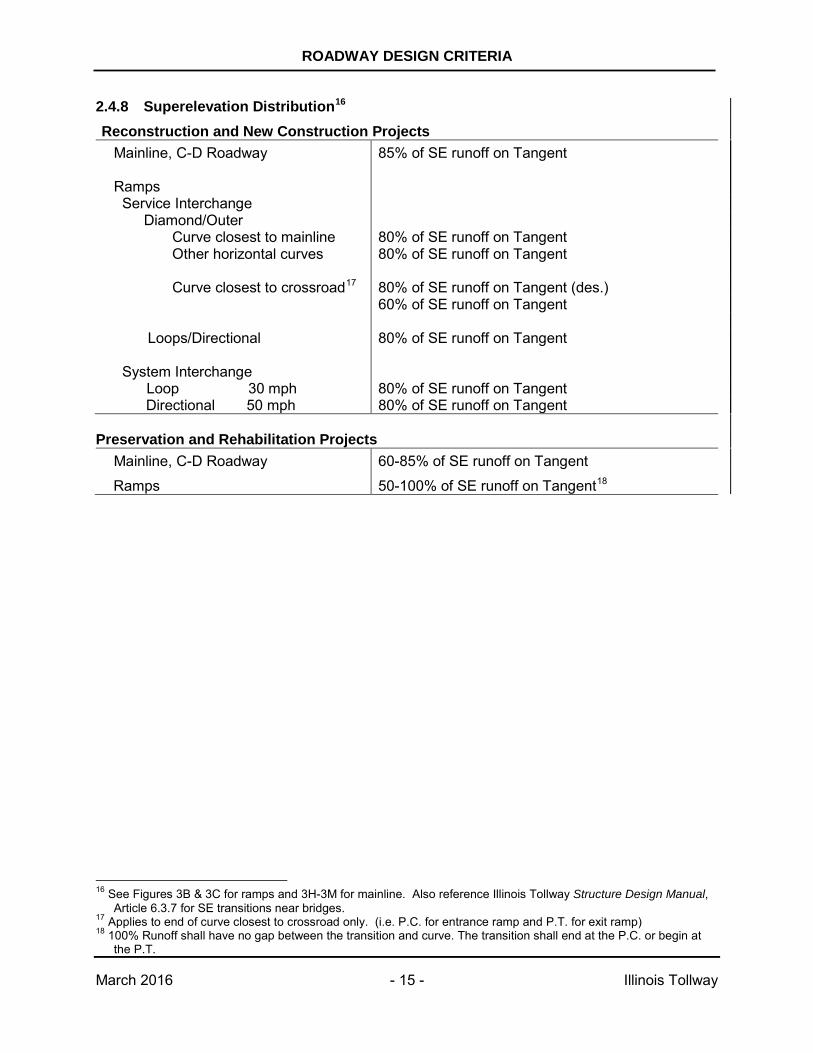
2.4.8 Superelevation Distribution16 Reconstruction and New Construction Projects
Mainline, C-D Roadway 85% of SE runoff on Tangent
Ramps Service Interchange
Diamond/Outer Curve closest to mainline Other horizontal curves Curve closest to crossroad17 Loops/Directional
System Interchange Loop 30 mph
Directional 50 mph
80% of SE runoff on Tangent 80% of SE runoff on Tangent 80% of SE runoff on Tangent (des.) 60% of SE runoff on Tangent 80% of SE runoff on Tangent 80% of SE runoff on Tangent 80% of SE runoff on Tangent
Preservation and Rehabilitation Projects
Mainline, C-D Roadway
Ramps
60-85% of SE runoff on Tangent
50-100% of SE runoff on Tangent18
16 See Figures 3B & 3C for ramps and 3H-3M for mainline. Also reference Illinois Tollway Structure Design Manual,
Article 6.3.7 for SE transitions near bridges. 17 Applies to end of curve closest to crossroad only. (i.e. P.C. for entrance ramp and P.T. for exit ramp) 18 100% Runoff shall have no gap between the transition and curve. The transition shall end at the P.C. or begin at
the P.T.
ROADWAY DESIGN CRITERIA
March 2016 - 16 - Illinois Tollway
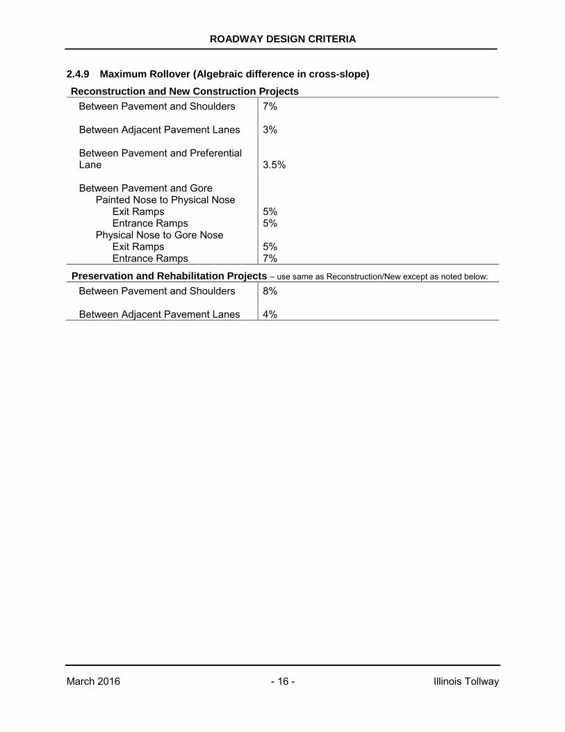
2.4.9 Maximum Rollover (Algebraic difference in cross-slope) Reconstruction and New Construction Projects
Between Pavement and Shoulders 7%
Between Adjacent Pavement Lanes Between Pavement and Preferential Lane
3% 3.5%
Between Pavement and Gore Painted Nose to Physical Nose
Exit Ramps Entrance Ramps
Physical Nose to Gore Nose Exit Ramps Entrance Ramps
5% 5% 5% 7%
Preservation and Rehabilitation Projects – use same as Reconstruction/New except as noted below: Between Pavement and Shoulders Between Adjacent Pavement Lanes
8% 4%
ROADWAY DESIGN CRITERIA
March 2016 - 17 - Illinois Tollway
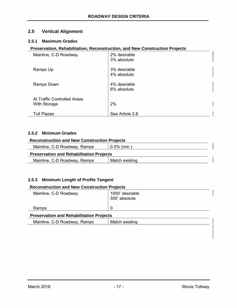
2.5 Vertical Alignment
2.5.1 Maximum Grades Preservation, Rehabilitation, Reconstruction, and New Construction Projects
Mainline, C-D Roadway 2% desirable 3% absolute
Ramps Up 3% desirable 4% absolute
Ramps Down 4% desirable 6% absolute
At Traffic Controlled Areas With Storage
2%
Toll Plazas
See Article 2.8
2.5.2 Minimum Grades Reconstruction and New Construction Projects
Mainline, C-D Roadway, Ramps 0.5% (min.)
Preservation and Rehabilitation Projects Mainline, C-D Roadway, Ramps Match existing
2.5.3 Minimum Length of Profile Tangent Reconstruction and New Construction Projects
Mainline, C-D Roadway 1000’ desirable 500’ absolute
Ramps 0
Preservation and Rehabilitation Projects Mainline, C-D Roadway, Ramps Match existing
ROADWAY DESIGN CRITERIA
March 2016 - 18 - Illinois Tollway
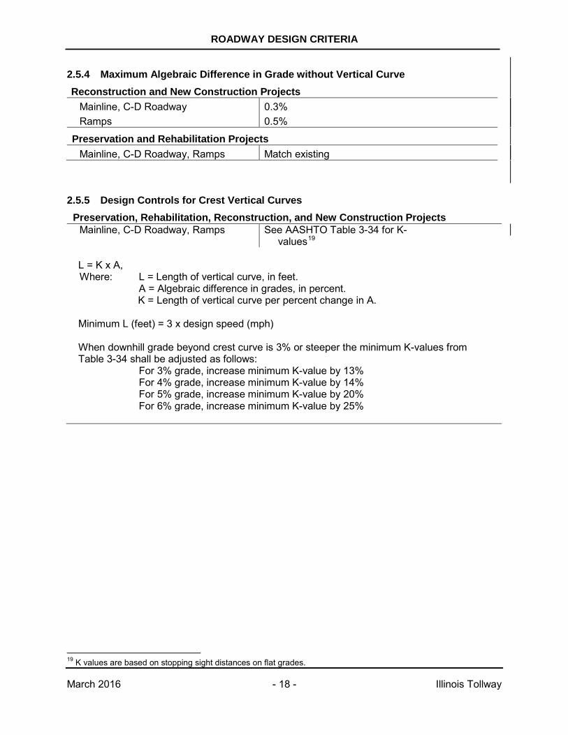
2.5.4 Maximum Algebraic Difference in Grade without Vertical Curve Reconstruction and New Construction Projects
Mainline, C-D Roadway Ramps
0.3% 0.5%
Preservation and Rehabilitation Projects Mainline, C-D Roadway, Ramps Match existing
2.5.5 Design Controls for Crest Vertical Curves Preservation, Rehabilitation, Reconstruction, and New Construction Projects
Mainline, C-D Roadway, Ramps
See AASHTO Table 3-34 for K-values19
L = K x A, Where: L = Length of vertical curve, in feet. A = Algebraic difference in grades, in percent.
K = Length of vertical curve per percent change in A. Minimum L (feet) = 3 x design speed (mph) When downhill grade beyond crest curve is 3% or steeper the minimum K-values from Table 3-34 shall be adjusted as follows:
For 3% grade, increase minimum K-value by 13% For 4% grade, increase minimum K-value by 14% For 5% grade, increase minimum K-value by 20% For 6% grade, increase minimum K-value by 25%
19 K values are based on stopping sight distances on flat grades.
ROADWAY DESIGN CRITERIA
March 2016 - 19 - Illinois Tollway
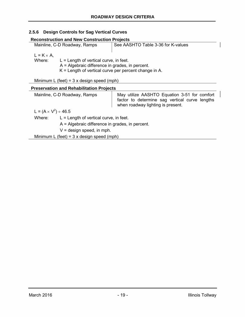
2.5.6 Design Controls for Sag Vertical Curves Reconstruction and New Construction Projects
Mainline, C-D Roadway, Ramps
See AASHTO Table 3-36 for K-values
L = K × A, Where: L = Length of vertical curve, in feet. A = Algebraic difference in grades, in percent.
K = Length of vertical curve per percent change in A. Minimum L (feet) = 3 x design speed (mph)
Preservation and Rehabilitation Projects Mainline, C-D Roadway, Ramps
May utilize AASHTO Equation 3-51 for comfort factor to determine sag vertical curve lengths when roadway lighting is present.
L = (A × V2) ÷ 46.5 Where: L = Length of vertical curve, in feet. A = Algebraic difference in grades, in percent. V = design speed, in mph. Minimum L (feet) = 3 x design speed (mph)
ROADWAY DESIGN CRITERIA
March 2016 - 20 - Illinois Tollway
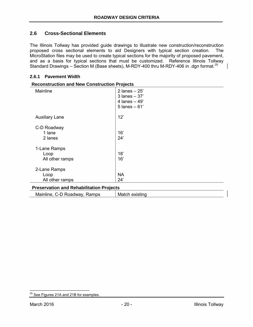
2.6 Cross-Sectional Elements The Illinois Tollway has provided guide drawings to illustrate new construction/reconstruction proposed cross sectional elements to aid Designers with typical section creation. The MicroStation files may be used to create typical sections for the majority of proposed pavement, and as a basis for typical sections that must be customized. Reference Illinois Tollway Standard Drawings – Section M (Base sheets), M-RDY-400 thru M-RDY-406 in .dgn format.20 2.6.1 Pavement Width Reconstruction and New Construction Projects
Mainline 2 lanes – 25’ 3 lanes – 37’ 4 lanes – 49’ 5 lanes – 61’
Auxiliary Lane C-D Roadway
1 lane 2 lanes
12’ 16’ 24’
1-Lane Ramps Loop
All other ramps
18’ 16’
2-Lane Ramps Loop All other ramps
NA 24’
Preservation and Rehabilitation Projects Mainline, C-D Roadway, Ramps Match existing
20 See Figures 21A and 21B for examples.
ROADWAY DESIGN CRITERIA
March 2016 - 21 - Illinois Tollway
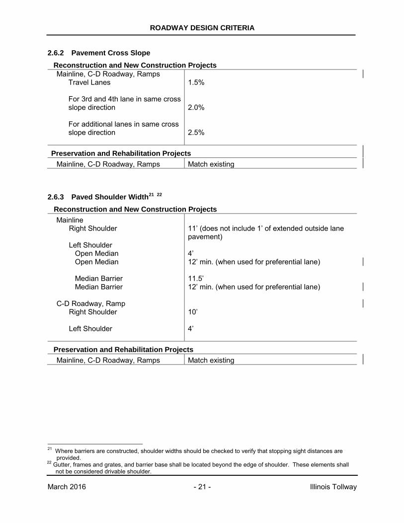
2.6.2 Pavement Cross Slope Reconstruction and New Construction Projects Mainline, C-D Roadway, Ramps
Travel Lanes
For 3rd and 4th lane in same cross slope direction
For additional lanes in same cross slope direction
1.5% 2.0% 2.5%
Preservation and Rehabilitation Projects Mainline, C-D Roadway, Ramps Match existing
2.6.3 Paved Shoulder Width21 22 Reconstruction and New Construction Projects Mainline
Right Shoulder
Left Shoulder
11’ (does not include 1’ of extended outside lane pavement)
Open Median Open Median Median Barrier Median Barrier
4’ 12’ min. (when used for preferential lane) 11.5’ 12’ min. (when used for preferential lane)
C-D Roadway, Ramp
Right Shoulder Left Shoulder
10’ 4’
Preservation and Rehabilitation Projects Mainline, C-D Roadway, Ramps Match existing
21 Where barriers are constructed, shoulder widths should be checked to verify that stopping sight distances are
provided. 22 Gutter, frames and grates, and barrier base shall be located beyond the edge of shoulder. These elements shall
not be considered drivable shoulder.
ROADWAY DESIGN CRITERIA
March 2016 - 22 - Illinois Tollway
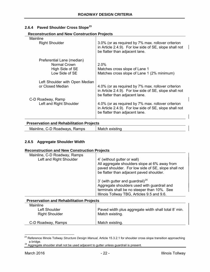
2.6.4 Paved Shoulder Cross Slope23 Reconstruction and New Construction Projects Mainline
Right Shoulder
Preferential Lane (median) Normal Crown High Side of SE Low Side of SE
Left Shoulder with Open Median or Closed Median
C-D Roadway, Ramp Left and Right Shoulder
3.0% (or as required by 7% max. rollover criterion in Article 2.4.9). For low side of SE, slope shall not be flatter than adjacent lane. 2.0% Matches cross slope of Lane 1 Matches cross slope of Lane 1 (2% minimum) 4.0% (or as required by 7% max. rollover criterion in Article 2.4.9). For low side of SE, slope shall not be flatter than adjacent lane. 4.0% (or as required by 7% max. rollover criterion in Article 2.4.9). For low side of SE, slope shall not be flatter than adjacent lane.
Preservation and Rehabilitation Projects Mainline, C-D Roadways, Ramps Match existing
2.6.5 Aggregate Shoulder Width Reconstruction and New Construction Projects
Mainline, C-D Roadway, Ramps Left and Right Shoulder
4’ (without gutter or wall) All aggregate shoulders slope at 6% away from paved shoulder. For low side of SE, slope shall not be flatter than adjacent paved shoulder. 3’ (with gutter and guardrail)24
Aggregate shoulders used with guardrail and terminals shall be no steeper than 10%. See Illinois Tollway TBG, Articles 9.5 and 9.6.
Preservation and Rehabilitation Projects Mainline Left Shoulder Right Shoulder C-D Roadway, Ramps
Paved width plus aggregate width shall total 8’ min. Match existing. Match existing.
23 Reference Illinois Tollway Structure Design Manual, Article 15.3.2.1 for shoulder cross slope transition approaching
a bridge. 24 Aggregate shoulder shall not be used adjacent to gutter unless guardrail is present.
ROADWAY DESIGN CRITERIA
March 2016 - 23 - Illinois Tollway
2.6.6 Use of Gutters and Curbs (Preservation, Rehabilitation, Reconstruction, and New Construction Projects) Cross slope and width of pavement and shoulders as well as longitudinal grade, affect the rate of runoff to the sideslope. Gutters and associated drainage structures at the edge of shoulder can be used to intercept pavement runoff where concentrated flows would otherwise cause erosion of the sideslope. However, the Designer shall consider other erosion control measures, to maximize the effective stormwater treatment train, prior to utilizing gutter. No portion of the gutter should be considered part of the rideable area of the shoulder or counted as part of the shoulder width. The use of gutters or curbs shall not create an obstacle for vehicles. The use of gutter is independent of the need for guardrail. Guardrail can be installed with or without gutter and gutter can be used with or without adjacent guardrail. The Illinois Tollway primarily uses two types – Gutter, Type G-3 is 3’ wide and is used along the mainline roadway; and Gutter, Type G-2 is 2’ wide and is used along ramps. The following tables show the use of Gutter, Type G-3 and Gutter, Type G-2, respectively. Note that in the Tables that the term “Not Preferred” does not preclude the use of gutter, if gutter is deemed necessary by the Designer. Gutter, Type G-3 (along Mainline and C-D Roadways) or Type G-2 (along Ramp) Gutter, Type G-3 or Type G-2 shall not be used along unshielded embankment foreslopes steeper than 1:6 (V:H). Gutter, Type G-3 or Type G-2 with a proper gutter transition shall be used at all Traffic Barrier Terminal Type T6 locations along the mainline or ramps. No drainage structure shall be located within the limits of the Terminal Type T6. Reference Illinois Tollway Standard Drawing B3.
ROADWAY DESIGN CRITERIA
March 2016 - 24 - Illinois Tollway
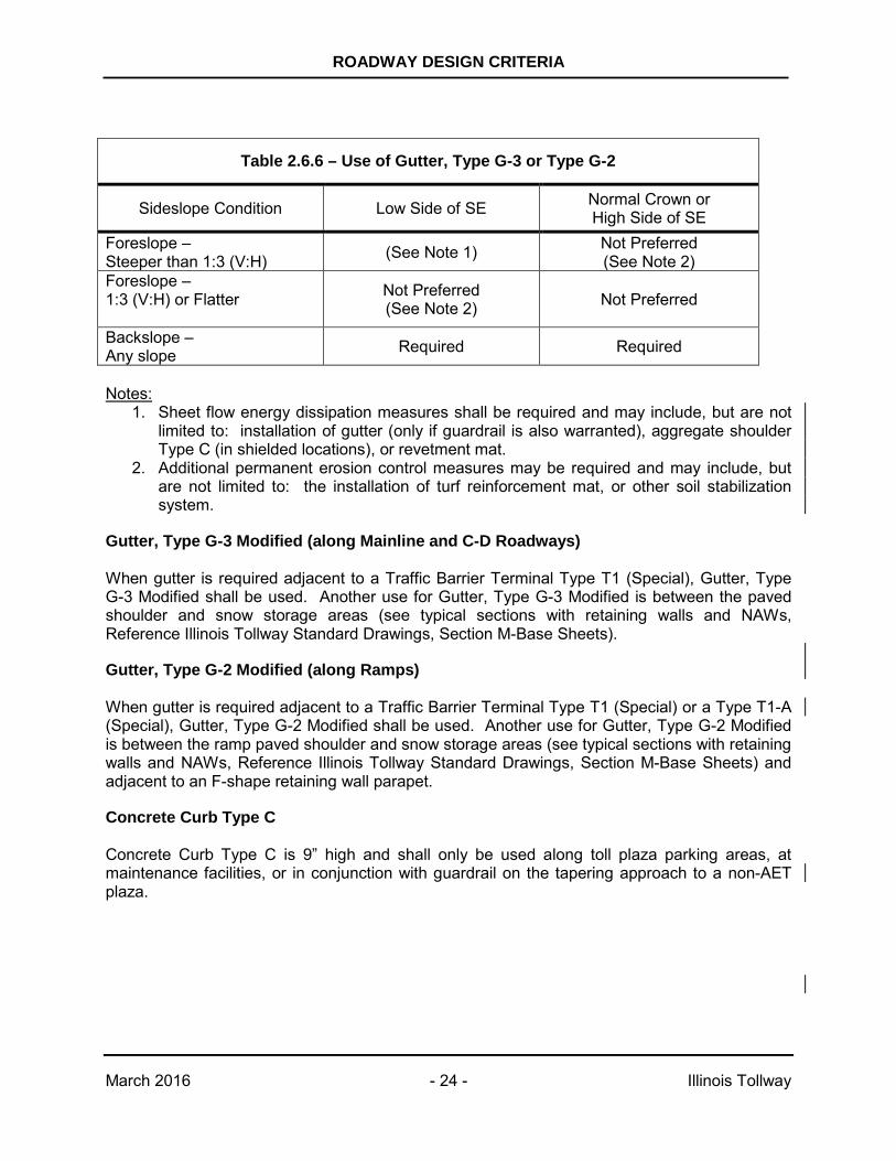
Notes:
1. Sheet flow energy dissipation measures shall be required and may include, but are not limited to: installation of gutter (only if guardrail is also warranted), aggregate shoulder Type C (in shielded locations), or revetment mat.
2. Additional permanent erosion control measures may be required and may include, but are not limited to: the installation of turf reinforcement mat, or other soil stabilization system.
Gutter, Type G-3 Modified (along Mainline and C-D Roadways) When gutter is required adjacent to a Traffic Barrier Terminal Type T1 (Special), Gutter, Type G-3 Modified shall be used. Another use for Gutter, Type G-3 Modified is between the paved shoulder and snow storage areas (see typical sections with retaining walls and NAWs, Reference Illinois Tollway Standard Drawings, Section M-Base Sheets).
Gutter, Type G-2 Modified (along Ramps) When gutter is required adjacent to a Traffic Barrier Terminal Type T1 (Special) or a Type T1-A (Special), Gutter, Type G-2 Modified shall be used. Another use for Gutter, Type G-2 Modified is between the ramp paved shoulder and snow storage areas (see typical sections with retaining walls and NAWs, Reference Illinois Tollway Standard Drawings, Section M-Base Sheets) and adjacent to an F-shape retaining wall parapet.
Concrete Curb Type C
Concrete Curb Type C is 9” high and shall only be used along toll plaza parking areas, at maintenance facilities, or in conjunction with guardrail on the tapering approach to a non-AET plaza.
Table 2.6.6 – Use of Gutter, Type G-3 or Type G-2
Sideslope Condition Low Side of SE Normal Crown or High Side of SE
Foreslope – Steeper than 1:3 (V:H) (See Note 1) Not Preferred
(See Note 2) Foreslope – 1:3 (V:H) or Flatter
Not Preferred (See Note 2) Not Preferred
Backslope – Any slope Required Required
ROADWAY DESIGN CRITERIA
March 2016 - 25 - Illinois Tollway
2.6.7 Snow Storage Area (Preservation, Rehabilitation, Reconstruction, and New Construction Projects) During snow removal operations, Illinois Tollway Maintenance can usually push snow up and over a 42” high barrier or parapet to clear the shoulder of snow. When removal of snow over the parapet is not possible or not allowed (such as along a bridge), the snow can be pushed longitudinally along the parapet for a distance of approximately 500’. For lengths exceeding 500’, an additional area adjacent to the full width shoulder should be provided for the storage of snow. The snow storage area should be desirably 6’ wide beyond the modified gutter, and drain at 5% toward the modified gutter that is adjacent to the shoulder. Transitions upstream and downstream of the snow storage area shall be addressed by the Designer. Additional width for snow storage is generally not provided on bridges. See Illinois Tollway Standard Drawings, Section M – Base Sheets, for typical section details and Illinois Tollway Structure Design Manual for retaining wall parapet details. For Preservation and Rehabilitation projects, contact Illinois Tollway Maintenance for areas of concern regarding snow storage. Retaining Wall A snow storage area should be provided between the outside shoulder and the retaining wall when there is a:
• Cut wall (roadway is lower than adjacent ground) where the vertical distance from the paved shoulder surface to the top of wall exceeds 42”;
• Fill wall (roadway is higher than adjacent ground) when there is a NAW mounted on top
of the parapet;
• Fill wall where snow cannot be thrown over the parapet because the low side of the wall is environmentally sensitive or private property.
Ground-Mounted Noise Abatement Wall For ground-mounted NAWs located near the edge of shoulder, a snow storage area shall be provided between the outside shoulder and the NAW. See Illinois Tollway Structure Design Manual for barrier requirements in front of a ground-mounted NAW. The snow storage area should be paved with 6” asphalt shoulder material or similar. Snow storage is not required when the proposed NAW is located near the ROW line.
ROADWAY DESIGN CRITERIA
March 2016 - 26 - Illinois Tollway
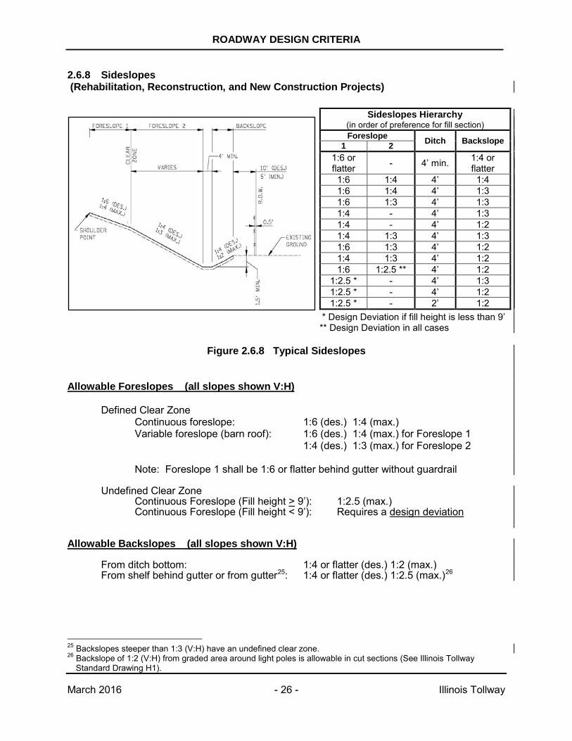
2.6.8 Sideslopes (Rehabilitation, Reconstruction, and New Construction Projects)
* Design Deviation if fill height is less than 9’ ** Design Deviation in all cases
Figure 2.6.8 Typical Sideslopes
Allowable Foreslopes (all slopes shown V:H)
Defined Clear Zone Continuous foreslope: 1:6 (des.) 1:4 (max.) Variable foreslope (barn roof): 1:6 (des.) 1:4 (max.) for Foreslope 1
1:4 (des.) 1:3 (max.) for Foreslope 2
Note: Foreslope 1 shall be 1:6 or flatter behind gutter without guardrail
Undefined Clear Zone Continuous Foreslope (Fill height > 9’): 1:2.5 (max.) Continuous Foreslope (Fill height < 9’): Requires a design deviation
Allowable Backslopes (all slopes shown V:H)
From ditch bottom: 1:4 or flatter (des.) 1:2 (max.) From shelf behind gutter or from gutter25: 1:4 or flatter (des.) 1:2.5 (max.)26
25 Backslopes steeper than 1:3 (V:H) have an undefined clear zone. 26 Backslope of 1:2 (V:H) from graded area around light poles is allowable in cut sections (See Illinois Tollway
Standard Drawing H1).
Sideslopes Hierarchy (in order of preference for fill section) Foreslope Ditch Backslope 1 2
1:6 or flatter - 4’ min. 1:4 or
flatter 1:6 1:4 4’ 1:4 1:6 1:4 4’ 1:3 1:6 1:3 4’ 1:3 1:4 - 4’ 1:3 1:4 - 4’ 1:2 1:4 1:3 4’ 1:3 1:6 1:3 4’ 1:2 1:4 1:3 4’ 1:2 1:6 1:2.5 ** 4’ 1:2
1:2.5 * - 4’ 1:3 1:2.5 * - 4’ 1:2 1:2.5 * - 2’ 1:2
ROADWAY DESIGN CRITERIA
March 2016 - 27 - Illinois Tollway
Desirable sideslope transition lengths Applies from steeper to flatter and vice versa Applies to foreslope transitions or backslope transitions
Transition from 1:6 to 1:4 in 150’ Transition from 1:6 to 1:3 in 200’ Transition from 1:6 to 1:2.5 in 250’ Transition from 1:4 to 1:3 in 75’ Transition from 1:4 to 1:2.5 in 100’
Note that transitioning from a foreslope to a backslope (or vice versa) should be done such that the transverse slope created is within allowable grades (see IL Tollway TBG, Article 5.5.10). (Preservation Projects)
Allowable Foreslopes
Match Existing
Allowable Backslopes Match Existing
2.6.9 Ditch Bottom Width Preservation, Rehabilitation, Reconstruction, and New Construction Projects If accessible by errant vehicles
All other locations
4.0’ (minimum) 4.0’ (desirable) 2.0’ (minimum)
ROADWAY DESIGN CRITERIA
March 2016 - 28 - Illinois Tollway
2.6.10 Gore Area Cross Slopes
Ideally, the entire paved gore area should drain away from the mainline and onto the ramp pavement. The gore pavement shall never be sloped to drain toward the mainline lanes. If absolutely necessary, the gore may be sloped to drain toward its middle by creation of a swale. Trench drain and drainage structures within the gore pavement shall be minimized. When a swale is used the following cross slope criteria shall be met:
Preservation, Rehabilitation, Reconstruction, and New Construction Projects Within shoulder width
3.0% (maximum) for mainline side of swale 4.0% (maximum) for ramp side of swale
The grass area downstream from the paved gore area of an exit ramp and upstream from the paved gore area of an entrance ramp shall be graded according to the following:
Preservation, Rehabilitation, Reconstruction, and New Construction Projects Grass area beyond paved area for first 200’ (400’ desirable for exit ramps)
1:6 (V:H) or flatter Note: Infield slopes shall be as flat as practical not to exceed maximums set for foreslopes and backslopes.
2.6.11 Rumble Strips, Delineation Devices and Markings (Preservation, Rehabilitation, Reconstruction, and New Construction Projects)
Shoulder rumble strips shall be installed along full width (10’ min.) shoulders for:
• Mainline roadway (median and outside). • Auxiliary lanes that are 1000’ or longer. • C-D roads that are 1000’ or longer (left and right).
Rumble strips shall not be installed along ramps, ramp terminals, and most bridges.
For bus-on-shoulder usage, the Designer shall provide a rumble strip detail based on shoulder width, location of edgeline pavement marking, presence of barrier and other site conditions.
See details shown in Illinois Tollway Standard Drawings D4, D5, D6 and D8 for barrier delineation devices and markings.
ROADWAY DESIGN CRITERIA
March 2016 - 29 - Illinois Tollway
2.6.12 Emergency Turnarounds (Preservation, Rehabilitation, Reconstruction, and New Construction Projects)
Emergency turnarounds shall be located at sites that allow a minimum of 1000’ clear stopping sight distance in both directions. The location selected shall be acceptable to the Illinois Tollway’s Maintenance staff and the Illinois State Police, District 15.
A clearance opening of 30’ shall be provided between the impact attenuators placed at each end of the opening in the median barrier wall to allow for emergency vehicles to maneuver.
For a median width of 35’ or greater, the median barriers should be offset at the turnaround. See Illinois Tollway Standard Drawing, Section M – Base Sheet M-RDY-411.
2.6.13 Crash Investigation Sites (Preservation, Rehabilitation, Reconstruction, and New Construction Projects) Location
• Placed at full interchanges. o Preferably locations without tolls to get on and off system. o Do not place inside cloverleaf interchanges. o Place in ramp infields between an outer ramp and the mainline.
• At mainline plazas downstream of toll booth. • ¼ to ½ mile downstream from emergency turnarounds. • Approximately every 4 miles in rural areas. • Approximately every 2 to 3 miles in urban areas. • Site should be combined with radio tower access roads and ITS communication
structures, where possible.
Layout
• Usually trapezoidal in shape. • Desirable size: 150’ long (not including tapers) by 40’ wide (measured from outside
edge of paved shoulder). • Desirable tapers: 3:1 tapers on upstream and downstream side of site. Consider a
flatter taper on downstream side for efficient acceleration. • Positive protection (either guardrail or barrier wall) required at proper offset from edge of
traveled way. If guardrail is used, the length shall meet the minimum length requirement for a free-standing installation. A barrier warrant is not required for this installation.
• Entrance and exit vehicle path width shall be 20’ minimum (measured perpendicular from back of guardrail or concrete barrier to edge of site).
• No additional ROW should be acquired for site. • If absolutely necessary, the site may be narrowed or shortened (but not both) to fit into
existing ROW. • Snow storage is not needed behind site. • Slope to drain away from mainline.
ROADWAY DESIGN CRITERIA
March 2016 - 30 - Illinois Tollway
Signing (see Illinois Tollway Roadway Signing and Pavement Marking Guidelines)
Other Considerations
• Site shall have adequate lighting. See Illinois Tollway Guidelines for Roadway Illumination, Article 6.7, for guidance on breakaway devices. Light poles shall not be ground-mounted within the paved area.
• Site shall have CCTV camera coverage. • Traffic detectors may be installed.
For Preservation and Rehabilitation projects, contact Illinois Tollway Maintenance regarding crash investigation sites.
ROADWAY DESIGN CRITERIA
March 2016 - 31 - Illinois Tollway
2.7 New Structures
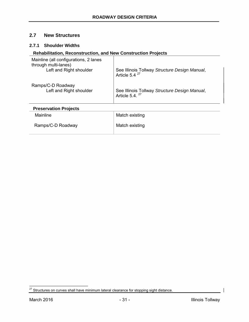
2.7.1 Shoulder Widths Rehabilitation, Reconstruction, and New Construction Projects
Mainline (all configurations, 2 lanes through multi-lanes)
Left and Right shoulder
Ramps/C-D Roadway
Left and Right shoulder
See Illinois Tollway Structure Design Manual, Article 5.4 27 See Illinois Tollway Structure Design Manual, Article 5.4. 27
Preservation Projects Mainline Match existing
Ramps/C-D Roadway Match existing
27 Structures on curves shall have minimum lateral clearance for stopping sight distance.
ROADWAY DESIGN CRITERIA
March 2016 - 32 - Illinois Tollway
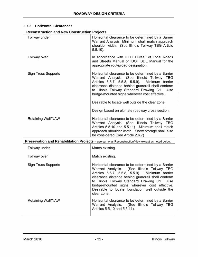
2.7.2 Horizontal Clearances Reconstruction and New Construction Projects Tollway under Horizontal clearance to be determined by a Barrier
Warrant Analysis. Minimum shall match approach shoulder width. (See Illinois Tollway TBG Article 5.5.10).
Tollway over In accordance with IDOT Bureau of Local Roads and Streets Manual or IDOT BDE Manual for the appropriate route/road designation.
Sign Truss Supports Retaining Wall/NAW
Horizontal clearance to be determined by a Barrier Warrant Analysis. (See Illinois Tollway TBG Articles 5.5.7, 5.5.8, 5.5.9). Minimum barrier clearance distance behind guardrail shall conform to Illinois Tollway Standard Drawing C1. Use bridge-mounted signs wherever cost effective. Desirable to locate well outside the clear zone. Design based on ultimate roadway cross section. Horizontal clearance to be determined by a Barrier Warrant Analysis. (See Illinois Tollway TBG Articles 5.5.10 and 5.5.11). Minimum shall match approach shoulder width. Snow storage shall also be considered (See Article 2.6.7)
Preservation and Rehabilitation Projects – use same as Reconstruction/New except as noted below:
Tollway under Match existing.
Tollway over Match existing.
Sign Truss Supports Horizontal clearance to be determined by a Barrier Warrant Analysis. (See Illinois Tollway TBG Articles 5.5.7, 5.5.8, 5.5.9). Minimum barrier clearance distance behind guardrail shall conform to Illinois Tollway Standard Drawing C1. Use bridge-mounted signs wherever cost effective. Desirable to locate foundation well outside the clear zone.
Retaining Wall/NAW Horizontal clearance to be determined by a Barrier Warrant Analysis. (See Illinois Tollway TBG Articles 5.5.10 and 5.5.11).
ROADWAY DESIGN CRITERIA
March 2016 - 33 - Illinois Tollway
2.7.3 Vertical Clearances (Preservation, Rehabilitation, Reconstruction, and New Construction Projects)
Reference Illinois Tollway Structure Design Manual, Article 5.2 for all structure design vertical clearances.
2.7.4 Deck Cross Slope (Preservation, Rehabilitation, Reconstruction, and New Construction Projects)
Reference Illinois Tollway Structure Design Manual, Article 15.3 for deck cross slope criteria.
2.8 Toll Plazas (Preservation, Rehabilitation, Reconstruction, and New Construction Projects) Contact Illinois Tollway Engineering for current design criteria for all toll plazas. The horizontal design of a plaza varies with location, traffic volumes, queue length, deceleration diverges, and acceleration merges. The design for Dedicated I-PASS lanes introduces safety concerns that must be carefully considered. Each location should be individually analyzed and designed.
See Illinois Tollway Drainage Design Manual for toll plaza drainage requirements.
2.9 Roadside Safety (Preservation, Rehabilitation, Reconstruction, and New Construction Projects) The evaluation of lateral clear zones and roadside safety shall be in accordance with the AASHTO RDG, Latest Edition and the Illinois Tollway TBG, Latest Edition.
2.10 Access Control (Reconstruction and New Construction Projects) Access control shall be established in accordance with the Illinois Tollway, Interchange and Roadway Cost Sharing Policy, current version. See Appendix A.28 (Preservation and Rehabilitation Projects) Match existing access control, unless otherwise required for roadside safety improvements
2.11 Ramp Terminals (Reconstruction and New Construction Projects) Ramp terminals shall be in accordance with the Illinois Tollway’s Ramp Terminal Design Guidelines. See Figures 4 through 11 and 20. (Preservation and Rehabilitation Projects) Match existing ramp terminals.
28 Select largest value between Tables 1 and 2 for access control.
ROADWAY DESIGN CRITERIA
March 2016 - 34 - Illinois Tollway
2.12 Ramp/Roadway Convergence and Divergence Applications (New Construction and Reconstruction Projects) Major and minor convergences and divergences, or C-D Roadways configuration shall follow the IDOT’s BDE Manual, Latest Edition. Reference IDOT BDE Manual, Chapter 37, Interchanges. (Preservation and Rehabilitation Projects) Match existing convergences and divergences.
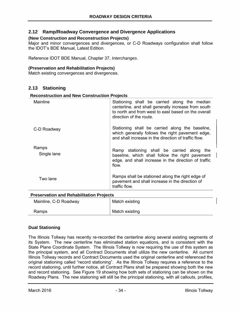
2.13 Stationing Reconstruction and New Construction Projects
Mainline
Stationing shall be carried along the median centerline, and shall generally increase from south to north and from west to east based on the overall direction of the route.
C-D Roadway Ramps
Single lane
Two lane
Stationing shall be carried along the baseline, which generally follows the right pavement edge, and shall increase in the direction of traffic flow. Ramp stationing shall be carried along the baseline, which shall follow the right pavement edge, and shall increase in the direction of traffic flow. Ramps shall be stationed along the right edge of pavement and shall increase in the direction of traffic flow.
Preservation and Rehabilitation Projects Mainline, C-D Roadway Ramps
Match existing Match existing
Dual Stationing
The Illinois Tollway has recently re-recorded the centerline along several existing segments of its System. The new centerline has eliminated station equations, and is consistent with the State Plane Coordinate System. The Illinois Tollway is now requiring the use of this system as the principal system, and all Contract Documents shall utilize the new centerline. All current Illinois Tollway records and Contract Documents used the original centerline and referenced the original stationing called “record stationing”. As the Illinois Tollway requires a reference to the record stationing, until further notice, all Contract Plans shall be prepared showing both the new and record stationing. See Figure 19 showing how both sets of stationing can be shown on the Roadway Plans. The new stationing will still be the principal stationing, with all callouts, profiles,
ROADWAY DESIGN CRITERIA
March 2016 - 35 - Illinois Tollway
typical sections, cross-sections, and schedules referencing only the new centerline stationing. The record stationing will also be shown at matchlines (alongside the new stationing), crossroad centerlines and at all record station equation points. A different font shall be used for the record stationing data.
2.14 Right-of-Way Limits (Preservation, Rehabilitation, Reconstruction, and New Construction Projects)
2.14.1 General
Whenever possible, ROW limits shall be set along relatively long tangents so as to provide a smooth line, rather than a series of short zigzag segments.
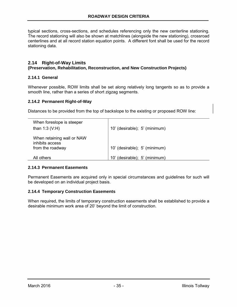
2.14.2 Permanent Right-of-Way
Distances to be provided from the top of backslope to the existing or proposed ROW line:
When foreslope is steeper than 1:3 (V:H) When retaining wall or NAW inhibits access from the roadway All others
10’ (desirable); 5’ (minimum) 10’ (desirable); 5’ (minimum) 10’ (desirable); 5’ (minimum)
2.14.3 Permanent Easements
Permanent Easements are acquired only in special circumstances and guidelines for such will be developed on an individual project basis.
2.14.4 Temporary Construction Easements
When required, the limits of temporary construction easements shall be established to provide a desirable minimum work area of 20’ beyond the limit of construction.
ROADWAY DESIGN CRITERIA
March 2016 - 36 - Illinois Tollway
2.15 Design Policy for the Evaluation of Mainline Superelevation Deficiencies for Preservation and Rehabilitation Projects
This policy has been prepared to provide direction to the Designer involved in pavement preservation and rehabilitation projects that include the evaluation of mainline SE deficiencies in the scope of services. Guidelines presented herein are applicable for the evaluation of existing mainline curves for rehabilitation projects on all routes of the Illinois Tollway System. Preservation projects are not required to evaluate mainline SE deficiencies unless explicitly included in the project scope.
2.15.1 Evaluation
Current requirements for mainline SE are indicated in Articles 2.4.6 through 2.4.8. In general, these criteria exceed those utilized in the design of the original system, and as a result, existing SE rates will be found to be less than currently required.
It is recognized that deficiencies may exist due either to initial construction or subsequent embankment settlement. Therefore, the Illinois Tollway’s policy for evaluating the SE on mainline curves in conjunction with pavement preservation and rehabilitation projects is as follows:
Mainline curves shall be corrected to the current SE rates if feasible. If not feasible then the mainline curves shall be corrected to the original SE rates.
SE transition length and SE distribution should match the original design.
2.15.2 Application of Policy
The application of this policy for the evaluation of mainline pavement SE should include the following steps at a minimum:
A. Record drawings shall be reviewed for pertinent information including stationing, curve data, SE rates, etc.
B. A field survey including verification of topographic information shown on record drawings and pavement cross-sectioning shall be performed to establish existing conditions.
C. The existing SE rates and transitions found during the field survey shall be compared to the current rates.
D. Where existing conditions meet the current rates, no correction is required. Pavement edge elevations shall be verified to ensure that smooth profiles exist, and adjustments shall be made as necessary.
ROADWAY DESIGN CRITERIA
March 2016 - 37 - Illinois Tollway
E. Where existing conditions are less than the current rates, the Designer must investigate and make recommendations for the most cost-effective method for establishing the current SE rate. Possible alternate methods include wedging with asphalt or complete replacement of the concrete pavement. Grinding of concrete pavement as a method for the correction of SE deficiencies is not allowed. Alternative methods should consider the limitations of construction materials and methods and the limits of correction which are practical. Pavement edge elevations should be shown on the plans.
If it is not feasible to meet the current SE rate due to overhead clearance issues, etc. the Designer must investigate and make recommendations for the most cost-effective method for re-establishing the original SE rate.
F. Shoulders adjacent to mainline resurfacing shall meet the new pavement overlay elevation. Additionally, all shoulders adjacent to mainline curves shall be checked for shoulder rollover deficiencies regardless of the need for SE correction.
The maximum algebraic difference between pavement and shoulder cross slopes shall not exceed the criteria in Article 2.4.9. Shoulder rollover rates exceeding criteria require correction of the shoulder cross-slope.
Generally, shoulder cross-slope can be corrected by the placement of an asphalt overlay on the existing shoulder. Shoulder cross-slope corrections on median shoulders require a determination of the limit of resurfacing possible within the constraint imposed by the median barrier wall. Shoulder overlay thickness shall not exceed the height of the vertical face at the bottom of the median barrier wall.
If the required shoulder overlay thickness exceeds the above limits on the barrier wall, modification of the barrier wall will be required. The Designer shall determine the most cost-effective method for such modification.
Breaking of the shoulder cross-slope for the correction of rollover deficiencies is generally not acceptable, except in special circumstances such as with the use of concrete shoulders and only with an approved Design Deviation.
G. Details, notes, special provisions, and pay items reflecting approved recommendations for the correction of SE deficiencies shall be developed and incorporated into the contract plans.
ROADWAY DESIGN CRITERIA
March 2016 - 38 - Illinois Tollway
2.16 Design Policy for the Evaluation of Ramp Superelevation Deficiencies for Preservation and Rehabilitation Projects
This policy has been prepared to provide direction to the Designer involved in pavement preservation and rehabilitation projects that include the evaluation of ramp SE deficiencies in the scope of services. Guidelines presented herein are applicable for the evaluation of existing ramp pavements for rehabilitation projects on all routes of the Illinois Tollway System. Preservation projects are not required to evaluate ramp SE deficiencies unless explicitly included in the project scope.
2.16.1 Evaluation
It is not possible to determine the exact SE rate utilized for ramp designs in all cases. Many of the original record plans call out SE rates in conjunction with ramp curve data and, in such cases, the original rates are easily verified. However, original roadway plans for several sections do not indicate any design ramp SE rates. Furthermore, field investigations have revealed variations between these criteria and actual conditions either due to inadequacies in the original construction or subsequent pavement deterioration. Current criteria for ramp SE are found in Article 2.4.6 through 2.4.8.
The evaluation of ramp SE can result in the following cases:
For cases where the original design meets or exceeds current criteria:
Case I: Existing SE rate equals original design rate.
Case II: Existing SE rate is less than original design rate but equal to or greater than current criteria.
Case III: Existing SE rate is less than current criteria.
In the case where the original design is less than current criteria:
Case IV: Existing SE rate is less than original design.
A. Case I
When the existing SE rate is equal to the original design rate, no correction is required. Since the rate for the existing system generally exceeds current criteria, this situation will normally result in higher SE rates than required. Corrective measures which reduce rates to meet current requirements are not to be made, but verification that existing rates meet or exceed these requirements is necessary. Pavement edge elevations should also be checked to insure that relatively smooth profiles exist. Adjustments should be made as necessary to produce smooth edge profiles.
B. Case II
Ramp pavement which exhibit SE rates less than those originally designed but still equal to or greater than current criteria should be handled in the same manner as Case I
ROADWAY DESIGN CRITERIA
March 2016 - 39 - Illinois Tollway
situations, and normally no corrective action is necessary. Verification that existing SE rates meet or exceed current requirements is required, and pavement edge elevations must be checked to ensure that relatively smooth profiles exist.
C. Case III
When SE rates are found to be less than current criteria, corrective measures are required. These measures shall result in the establishment of SE rates meeting those in these criteria. Special situations may be encountered where it is desirable to correct deficiencies to meet the original design rate (e.g., where a section of ramp is deficient, but the remainder meets the original design criteria, a smooth profile may not be attainable unless the deficient section is corrected to original criteria.
Corrective measures to increase ramp SE may include overlay wedging with asphalt or complete pavement replacement. Grinding of concrete pavement as a method for the correction of SE deficiencies is not allowed. The Designer shall make cost estimates of alternate corrective strategies to determine the most cost-effective method for correcting SE.
As in cases I and II, relatively smooth pavement edge profiles shall result from all corrective work.
D. Case IV
When SE rates are found to be less than original design rates and the original design rates are less than current criteria, corrective measures are required. These measures shall result in the establishment of the SE rates meeting the original design.
E. All Cases
The geometrics of all ramps shall be investigated to verify that posted ramp advisory speeds are adequate for existing curvature and SE rates or those to be provided. Where deficiencies are found, the Designer shall make recommendations for the correction of geometrics, SE, or signing.
SE transition length and SE distribution should match the original design.
2.16.2 Application of Policy
The application of this policy for the evaluation of ramp pavement SE should generally include the following steps:
A. Record drawings should be reviewed for pertinent geometric information including stationing, curve data, SE rates, etc., and other pertinent data.
B. Existing conditions should be established through a field survey. Survey work should include verification of topographic information shown on record drawings and cross-sectioning of ramp pavements and shoulders. Normally, only elevations at the edges of the pavement are required; however, additional elevations should be taken as needed to fully evaluate existing SE rates (e.g. at crown lines of two lane ramps).
ROADWAY DESIGN CRITERIA
March 2016 - 40 - Illinois Tollway
C. The existing SE rates and transitions found during the field survey should be evaluated against the criteria discussed herein and any deficiencies identified.
D. Recommendations for the correction of deficiencies should be developed and submitted to the Illinois Tollway. Recommendations should result from a cost-effective analysis of alternative corrective strategies and may include asphalt wedging, removal and replacement of concrete pavement, or do-nothing. Alternatives should consider the limitations of construction materials and methods and the limits of correction which are practical.
E. When ramp pavements are to be resurfaced either for the correction of SE deficiencies or as part of a general rehabilitation strategy, utilize current Illinois Tollway material as specified in the Standard Specifications or Special Provisions.
F. Where SE corrections are made or ramp pavements are resurfaced, appropriate shoulder reconstruction must also be made if elevation differences occur. Additionally, all ramp shoulders shall be checked for shoulder rollover deficiencies regardless of the need for SE correction.
The maximum algebraic difference between pavement and shoulder cross slopes shall not exceed the criteria in Article 2.4.9. Shoulder rollover rates exceeding criteria require correction of the shoulder cross-slope.
Generally, shoulder cross-slopes can be corrected by the placement of an asphalt overlay on the existing shoulder.
Breaking of the shoulder cross-slope for the correction of rollover deficiencies is generally not acceptable, except in special circumstances such as with the use of concrete shoulders and only with an approved Design Deviation.
G. Reviewed and approved recommendations shall be incorporated into the contract plans. Appropriate details, notes, special provisions, pay items, etc., shall be developed as required to fully identify the extent of work required.
ROADWAY DESIGN CRITERIA
March 2016 - 41 - Illinois Tollway
2.17 Guidelines for Replacement of Right-of-Way Fence along the Illinois Tollway System
(Preservation, Rehabilitation, Reconstruction, and New Construction Projects)
New construction and reconstruction projects should have all new Type 1 ROW fence in accordance with Illinois Tollway Standard Drawing D1. For preservation and rehabilitation projects, the replacement of Illinois Tollway ROW fence shall be in accordance with the current Illinois Tollway Standard Drawing D1 and design criteria, supplemented by the following:
2.17.1 Existing Fence
Existing 4-foot high ROW fence shall be replaced regardless of fence condition with a 6-foot high fence when ROW lines are adjacent to areas where pedestrians may be present such as:
• Residential, commercial or industrial areas • Golf courses • Playgrounds • Frontage roads
2.17.2 Forest Preserve
Generally, when the fence is adjacent to a forest preserve, the existing fence shall remain if in good condition and only sections which are damaged shall be replaced with fence of same kind and height. However, if a playground and/or bike trial is in the forest preserve adjacent to the ROW, the fence shall be replaced with 6-foot high fence.
2.17.3 Farmland
Generally, when the fence is adjacent to farmland and other remote areas, the existing fence shall remain if in good condition and only sections which are damaged shall be replaced with fence of same kind and height.
2.17.4 Relocation
No ROW fence shall be relocated without prior approval of the Illinois Tollway.
ROADWAY DESIGN CRITERIA
March 2016 - 42 - Illinois Tollway
SECTION 3.0 FIGURES List of Figures FIGURE 1 RESERVED
FIGURE 2 RESERVED
FIGURE 3A-3C RAMP SUPERELEVATION TRANSITIONS
FIGURE 3D-3G RESERVED
FIGURE 3H-3M MAINLINE SUPERELEVATION TRANSITIONS
FIGURE 4 TYPICAL ENTRANCE RAMP TERMINAL – PLAN
FIGURE 5 TYPICAL EXIT RAMP TERMINAL – PLAN
FIGURE 6 TYPICAL PARALLEL ENTRANCE RAMP TERMINAL – PLAN
FIGURE 7 TYPICAL PARALLEL EXIT RAMP TERMINAL – PLAN
FIGURE 8 TYPICAL TWO LANE ENTRANCE RAMP – PLAN
FIGURE 9 TYPICAL TWO LANE EXIT RAMP – PLAN
FIGURE 10 TYPICAL TWO LANE PARALLEL ENTRANCE RAMP – PLAN
FIGURE 11 TYPICAL TWO LANE PARALLEL EXIT RAMP – PLAN
FIGURE 12 RESERVED
FIGURE 13 RESERVED
FIGURE 14 RESERVED
FIGURE 15 RESERVED
FIGURE 16 RESERVED
FIGURE 17 RESERVED
FIGURE 18 RESERVED
FIGURE 19 TYPICAL PLAN DUAL STATIONING
FIGURE 20 TYPICAL EXIT RAMP TERMINAL WITH AUXILIARY LANE – PLAN
FIGURE 21A SAMPLE TYPICAL SECTION-MAINLINE
FIGURE 21B SAMPLE TYPICAL SECTION-RAMP
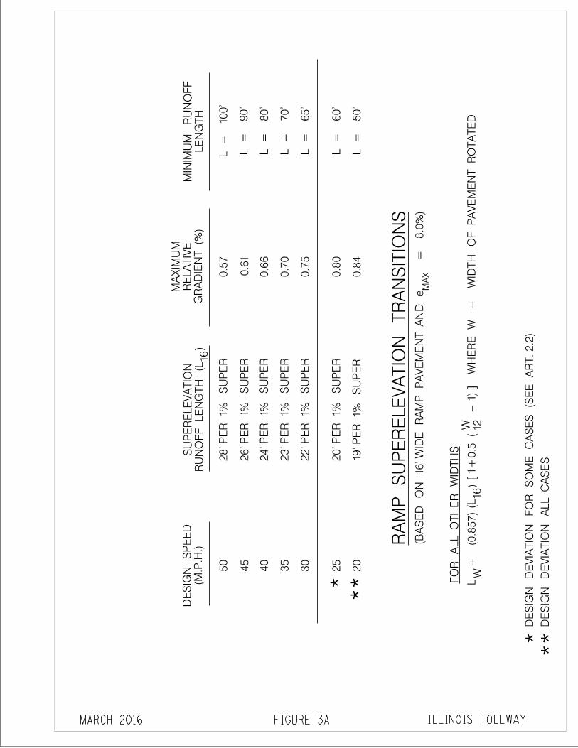
ILLINOIS TOLLWAY
RA
MP
SU
PE
RE
LE
VA
TIO
N T
RA
NS
ITIO
NS
FIGURE 3A
(M.P
.H.)
DE
SIG
N S
PE
ED
28' P
ER
1%
SU
PE
R
24' P
ER
1%
SU
PE
R
0.5
7
GR
AD
IEN
T (
%)
RE
LA
TIV
EM
AX
IMU
M
L =
10
0'
L =
80'
L =
70'
0.7
0
L =
90'
26' P
ER
1%
SU
PE
R
22' P
ER
1%
SU
PE
R
23' P
ER
1%
SU
PE
R
RU
NO
FF
LE
NG
TH
(L
)
SU
PE
RE
LE
VA
TIO
N
16
FO
R A
LL
OT
HE
R W
IDT
HS
W1
6
20' P
ER
1%
SU
PE
RL
=
60'
* *
*
19
' P
ER
1%
SU
PE
R
0.8
0
0.8
4
0.7
5L
=
65'
0.6
1
0.6
6
50
45
40
35
30
25
20
L =
50'
(BA
SE
D O
N 1
6' W
IDE
RA
MP
PA
VE
ME
NT
AN
D e
=
8.0
%)
MARCH 2016
LE
NG
TH
MIN
IMU
M R
UN
OF
F
*
- 1
) ]
W
HE
RE
W =
WID
TH
OF
PA
VE
ME
NT
RO
TA
TE
D1
2W
L =
(0.8
57) (
L ) [
1+
0.5
(
*D
ES
IGN
DE
VIA
TIO
N A
LL
CA
SE
S*
DE
SIG
N D
EV
IAT
ION
FO
R S
OM
E C
AS
ES
(S
EE
AR
T.
2.2
)
MA
X
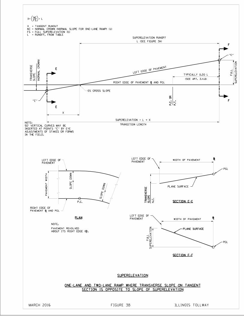
PA
VE
ME
NT
WID
TH
SL
OP
E
TR
AN
SV
ER
SE
PLANE SURFACE
P.T
.
P.C
. O
R
E
E
F
F
SL
OP
E
TR
AN
SV
ER
SE
SU
PE
RE
LE
VA
TIO
N
SU
PE
RE
LE
VA
TIO
N
FU
LL
SL
OP
E
TR
AN
SV
ER
SE
SECTION E-E
"C"
"C"
PLANE SURFACE
PLANE SURFACE
P.T
.
P.C
. O
R
SL
OP
E D
OW
N
SLOPE DO
WN
(NO
RM
AL
CR
OW
N)
SUPERELEVATION RUN0FF
FU
LL
TRANSITION LENGTH
PAVEMENT
LEFT EDGE OF \
\
N.C
.
PAVEMENT
LEFT EDGE OF
NOTE:
SUPERELEVATION
PLAN
X=FS
NCL
SECTION E-E
SECTION F-F
P.C.
IN THE FIELD.
ADJUSTMENTS OF STAKES OR FORMS
INSERTED AT POINTS "C" BY EYE
50' VERTICAL CURVES MAY BE
NOTE:
ABOUT ITS RIGHT EDGE (\).
PAVEMENT REVOLVED
LEFT EDGE OF PAVEMENT
RIGHT EDGE OF PAVEMENT \ AND PGL
PAVEMENT
LEFT EDGE OF
PAVEMENT \ AND PGL
RIGHT EDGE OF
PGL
PGL
SECTION IS OPPOSITE TO SLOPE OF SUPERELEVATION
ONE-LANE AND TWO-LANE RAMP WHERE TRANSVERSE SLOPE ON TANGENT
ILLINOIS TOLLWAYMARCH 2016 FIGURE 3B
L = RUNOFF, FROM TABLE
FS = FULL SUPERELEVATION (%)
NC = NORMAL CROWN (NORMAL SLOPE FOR ONE-LANE RAMP) (%)
X = TANGENT RUNOUT
WIDTH OF PAVEMENT
WIDTH OF PAVEMENT
X
SUPERELEVATION = L + X
L (SEE FIGURE 3A)
0% CROSS SLOPE
(SEE ART. 2.4.8)
TYPICALLY 0.20 L
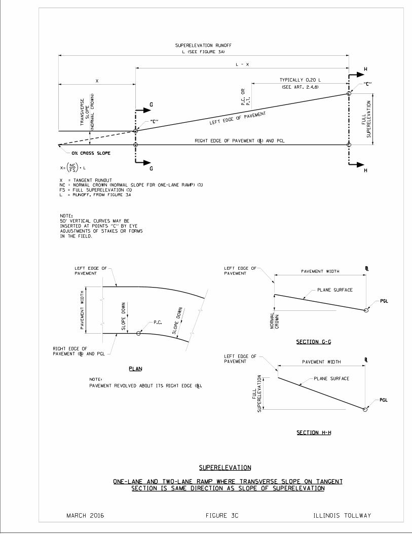
PA
VE
ME
NT
WID
TH
SL
OP
E D
OW
N
SLOPE DO
WN
S
UP
ER
EL
EV
AT
ION
FU
LL
PLANE SURFACE
PLANE SURFACE
G
G
H
H
S
UP
ER
EL
EV
AT
ION
FU
LL
P.T
.
P.C
. O
R
"C"
SUPERELEVATION RUN0FF
P.C.
CR
OW
N
NO
RM
AL
NOTE:
PLAN
SUPERELEVATION
SECTION G-G
SECTION H-H
\
\
PAVEMENT REVOLVED ABOUT ITS RIGHT EDGE (\).
IN THE FIELD.
ADJUSTMENTS OF STAKES OR FORMS
INSERTED AT POINTS "C" BY EYE
50' VERTICAL CURVES MAY BE
NOTE:
"C"
0% CROSS SLOPE
(NO
RM
AL
CR
OW
N)
SL
OP
E
TR
AN
SV
ER
SE
LEFT EDGE OF PAVEMENT
PAVEMENT
LEFT EDGE OF
PAVEMENT
LEFT EDGE OF
PGL
PGL
PAVEMENT
LEFT EDGE OFPAVEMENT (\) AND PGL
RIGHT EDGE OF
RIGHT EDGE OF PAVEMENT (\) AND PGL
SECTION IS SAME DIRECTION AS SLOPE OF SUPERELEVATION
ONE-LANE AND TWO-LANE RAMP WHERE TRANSVERSE SLOPE ON TANGENT
ILLINOIS TOLLWAYFIGURE 3CMARCH 2016
X=FS
NCL
L = RUNOFF, FROM FIGURE 3A
FS = FULL SUPERELEVATION (%)
NC = NORMAL CROWN (NORMAL SLOPE FOR ONE-LANE RAMP) (%)
X = TANGENT RUNOUT
PAVEMENT WIDTH
PAVEMENT WIDTH
L (SEE FIGURE 3A)
L - X
X
(SEE ART. 2.4.8)
TYPICALLY 0.20 L
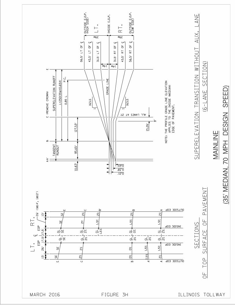
OF
TO
P S
UR
FA
CE
OF
PA
VE
ME
NT
SE
CT
ION
S
(35' M
ED
IAN
, 70 M
PH
DE
SIG
N S
PE
ED
)
MA
INL
INE
E
DG
E O
F P
AV
EM
EN
T.
A
PP
LIE
S T
O T
HE
IN
SID
E (
ME
DIA
N)
NO
TE
: T
HE
PR
OF
ILE
GR
AD
E L
INE
EL
EV
AT
ION
(6-L
AN
E S
EC
TIO
N)
SU
PE
RE
LE
VA
TIO
N T
RA
NS
ITIO
N W
ITH
OU
T A
UX
. L
AN
E
13'
26'
13
'1
7.5
'17
.5'
EO
PE
OP
LT
.R
T.
C L
OUTSIDE EOP
OUTSIDE EOP
INSIDE EOP
INSIDE EOP
AA
A'
B
C
E
B'
B
C
E
GL
GL
GL
GL
GL
1.5
%
1.5
%1.5
%
0%
2%
0%
2%
2%
SE
SE
GL
GL
GL
GL
GL
1.5
%2%
1.5
%2%
2%
1.5
%
2%
2%
SE
SE
L56.5
' L
T O
F C
31.5
' R
T O
F C
L
43
.5' R
T O
F C
L
56
.5' R
T O
F C
LL3
1.5
' L
T O
F C
L4
3.5
' L
T O
F C
GR
AD
E L
INE
0.21'
0.39'
0.65'
14e 14e
39e 39e
AA
'B
E
B'
10.6
3'
95
.65
'1
27
.53
'
21.2
6'
RU
NO
UT
TA
NG
EN
TS
UP
ER
EL
EV
AT
ION
RU
NO
FF
L=
25
0(3
9e)(0
.65
4)
P.C
.
16
3.5
1
16
3.5
1R
T.
LT
.
IN
SID
E E
.O.P
.
(HIG
H S
IDE
)O
UT
SID
E E
.O.P
.
(LO
W S
IDE
)O
UT
SID
E E
.O.P
.
ALL LANES AT 2%
0.8
5 L
26' (1@
14', 1
@12')
C (
RE
MO
VE
CR
OW
N)
FIGURE 3H ILLINOIS TOLLWAY
2%
2%
2%
2%
0%
1.5
%
2%
2%
SE
SE
MARCH 2016
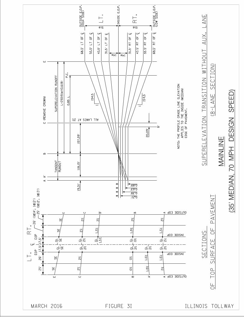
(8-L
AN
E S
EC
TIO
N)
SU
PE
RE
LE
VA
TIO
N T
RA
NS
ITIO
N W
ITH
OU
T A
UX
. L
AN
E
OF
TO
P S
UR
FA
CE
OF
PA
VE
ME
NT
SE
CT
ION
S
(35' M
ED
IAN
, 70 M
PH
DE
SIG
N S
PE
ED
)
MA
INL
INE
25
'26'
17
.5'1
7.5
'
EO
PE
OP
LT
.R
T.
C L
OUTSIDE EOP
OUTSIDE EOP
INSIDE EOP
INSIDE EOP
AA
A'
B
C
E
B'
B
C
E
GL
GL
GL
GL
GL
1.5
%
1.5
%1.5
%
0%
2%
0%
2%
2%
SE
SE
GL
GL
GL
GL
GL
1.5
%2%
1.5
%2%
2%
1.5
%
2%
2%
SE
SE
E
DG
E O
F P
AV
EM
EN
T.
A
PP
LIE
S T
O T
HE
IN
SID
E (
ME
DIA
N)
NO
TE
: T
HE
PR
OF
ILE
GR
AD
E L
INE
EL
EV
AT
ION
0.21'
0.39'
0.63'
0.89'
AA
'B
E
B'
19
.31
'
RU
NO
UT
TA
NG
EN
T
51e (LO
W S
IDE
)O
UT
SID
E E
.O.P
.
51e
RT
.
IN
SID
E E
.O.P
.
LT
.
(HIG
H S
IDE
)O
UT
SID
E E
.O.P
.
14e 14e 31.5
' R
T O
F C
LL3
1.5
' L
T O
F C
L4
3.5
' L
T O
F C
L5
5.5
' L
T O
F C
L68.5
' L
T O
F C
43
.5' R
T O
F C
L
55
.5' R
T O
F C
L
68
.5' R
T O
F C
L
P.C
.
1
15
4.5
1
15
4.5
L=
25
0(5
1e)(0
.61
8)
118.1
9'
15
7.5
9'
20.0
9'
SU
PE
RE
LE
VA
TIO
N R
UN
OF
F
ALL LANES AT 2%
0.8
5 L
26' (1@
14', 1
@12')
25' (1@
12', 1
@13')
C (
RE
MO
VE
CR
OW
N)
FIGURE 3I ILLINOIS TOLLWAY
2%
2%
2%
2%
0%
1.5
%
2%
2%
SE
SE
MARCH 2016
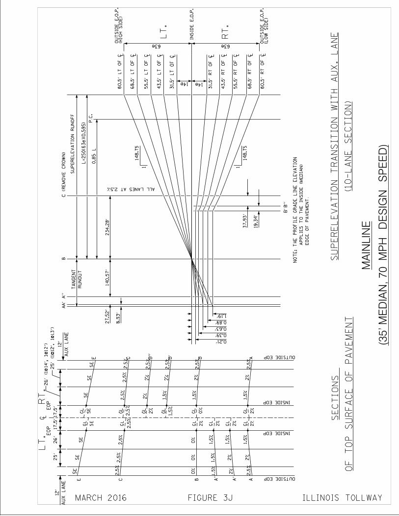
(10-L
AN
E S
EC
TIO
N)
SU
PE
RE
LE
VA
TIO
N T
RA
NS
ITIO
N W
ITH
AU
X. L
AN
E
OF
TO
P S
UR
FA
CE
OF
PA
VE
ME
NT
SE
CT
ION
S
(35' M
ED
IAN
, 70 M
PH
DE
SIG
N S
PE
ED
)
MA
INL
INE
25
'26'
17
.5'1
7.5
'
EO
PE
OP
LT
.R
T.
C L
OUTSIDE EOP
OUTSIDE EOP
INSIDE EOP
INSIDE EOP
AA
A"
B
C
E
B'
B
C
E
GL
GL
GL
GL
GL
1.5
%
1.5
%1.5
%
0%
2%
0%
SE
SE
GL
GL
GL
GL
GL
1.5
%2%
1.5
%2%
2%
1.5
%
SE
SE
2.5
%2.5
%
0%
1.5
%
GL
1.5
%2%
2%
A'
2.5
%
2.5
%2.5
%2.5
%2.5
%2.5
%2.5
%
2.5
%
B"
2.5
%2%
GL
2%
SE
SE
AU
X L
AN
E
12'
0.21'
0.39'
0.63'
0.89'
1.19'
(HIG
H S
IDE
)O
UT
SID
E E
.O.P
.
LT
.
IN
SID
E E
.O.P
.
63e
(LO
W S
IDE
)O
UT
SID
E E
.O.P
.
63e
RU
NO
UT
TA
NG
EN
T
8.9
3'
27.5
2'AA
'A
"B
SU
PE
RE
LE
VA
TIO
N R
UN
OF
F
L=
25
0(6
3e)(0
.59
5)
0.8
5 L
E
DG
E O
F P
AV
EM
EN
T.
A
PP
LIE
S T
O T
HE
IN
SID
E (
ME
DIA
N)
NO
TE
: T
HE
PR
OF
ILE
GR
AD
E L
INE
EL
EV
AT
ION
14e 14e
L3
1.5
' L
T O
F C
L4
3.5
' L
T O
F C
L5
5.5
' L
T O
F C
L68.5
' L
T O
F C
L80.5
' L
T O
F C
L31.5
' R
T O
F C
L4
3.5
' R
T O
F C
L5
5.5
' R
T O
F C
L6
8.5
' R
T O
F C
L80.5
' R
T O
F C
B"
B'
19
.34
'
37.9
3'
ALL LANES AT 2.5%
P.C
.
23
4.2
8'
140.5
7'
1
148.7
5
26' (1@
14', 1
@12')
25' (1@
12', 1
@13')
AU
X L
AN
E
12
'C
(R
EM
OV
E C
RO
WN
)
FIGURE 3J ILLINOIS TOLLWAY
2%
2%
2%
2%
2%
0%
1.5
%
2%
2.5
%2.5
%
SE
SE
MARCH 2016
1
148.7
5
RT
.
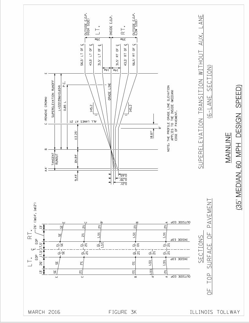
(35' M
ED
IAN
, 60 M
PH
DE
SIG
N S
PE
ED
)
MA
INL
INE
OF
TO
P S
UR
FA
CE
OF
PA
VE
ME
NT
SE
CT
ION
S
E
DG
E O
F P
AV
EM
EN
T.
A
PP
LIE
S T
O T
HE
IN
SID
E (
ME
DIA
N)
NO
TE
: T
HE
PR
OF
ILE
GR
AD
E L
INE
EL
EV
AT
ION
(6-L
AN
E S
EC
TIO
N)
SU
PE
RE
LE
VA
TIO
N T
RA
NS
ITIO
N W
ITH
OU
T A
UX
. L
AN
E
13
'26'
13
'1
7.5
'17
.5'
EO
PE
OP
LT
.R
T.
C L
OUTSIDE EOP
OUTSIDE EOP
INSIDE EOP
INSIDE EOPL
56.5
' L
T O
F C
31.5
' R
T O
F C
L
43
.5' R
T O
F C
L
56
.5' R
T O
F C
LL3
1.5
' L
T O
F C
L4
3.5
' L
T O
F C
GR
AD
E L
INE
0.21'
0.39'
0.65'
14e 14e
39e 39e
AA
A'
B
C
E
B'
B
C
E
AA
'B
E
B'
9.4
4'
84.9
4'
113.2
5'
18
.87
'
RU
NO
UT
TA
NG
EN
TS
UP
ER
EL
EV
AT
ION
RU
NO
FF
L=
22
2(3
9e)(0
.65
4)
P.C
.
14
5.2
1
14
5.2
1R
T.
LT
.
IN
SID
E E
.O.P
.
(HIG
H S
IDE
)O
UT
SID
E E
.O.P
.
(LO
W S
IDE
)O
UT
SID
E E
.O.P
.
ALL LANES AT 2%
GL
GL
GL
GL
GL
1.5
%
1.5
%1.5
%
0%
2%
0%
2%
2%
SE
SE
GL
GL
GL
GL
GL
1.5
%2%
1.5
%2%
2%
1.5
%
2%
2%
SE
SE
0.8
5 L
26' (1@
14', 1
@12')
C (
RE
MO
VE
CR
OW
N)
FIGURE 3K ILLINOIS TOLLWAY
2%
2%
2%
2%
0%
1.5
%
2%
2%
SE
SE
MARCH 2016
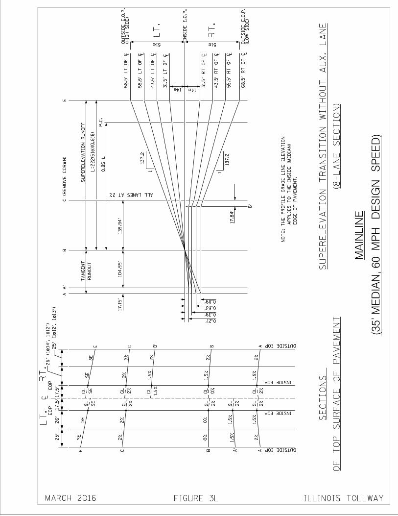
(35' M
ED
IAN
, 60 M
PH
DE
SIG
N S
PE
ED
)
MA
INL
INE
(8-L
AN
E S
EC
TIO
N)
SU
PE
RE
LE
VA
TIO
N T
RA
NS
ITIO
N W
ITH
OU
T A
UX
. L
AN
E
OF
TO
P S
UR
FA
CE
OF
PA
VE
ME
NT
SE
CT
ION
S
E
DG
E O
F P
AV
EM
EN
T.
A
PP
LIE
S T
O T
HE
IN
SID
E (
ME
DIA
N)
NO
TE
: T
HE
PR
OF
ILE
GR
AD
E L
INE
EL
EV
AT
ION
25
'26'
17
.5'1
7.5
'
EO
PE
OP
LT
.R
T.
C L
OUTSIDE EOP
OUTSIDE EOP
INSIDE EOP
INSIDE EOP
AA
A'
B
C
E
B'
B
C
E
GL
GL
GL
GL
GL
1.5
%
1.5
%1.5
%
0%
2%
0%
2%
2%
SE
SE
GL
GL
GL
GL
GL
1.5
%2%
1.5
%2%
2%
1.5
%
2%
2%
SE
SE
0.21'
0.39'
0.63'
0.89'
AA
'B
E
B'
17
.15
'
RU
NO
UT
TA
NG
EN
T
51e (LO
W S
IDE
)O
UT
SID
E E
.O.P
.
51e
RT
.
IN
SID
E E
.O.P
.
LT
.
(HIG
H S
IDE
)O
UT
SID
E E
.O.P
.
14e 14e 31.5
' R
T O
F C
LL3
1.5
' L
T O
F C
L4
3.5
' L
T O
F C
L5
5.5
' L
T O
F C
L68.5
' L
T O
F C
43
.5' R
T O
F C
L
55
.5' R
T O
F C
L
68
.5' R
T O
F C
L
P.C
.
1
13
7.2
1
13
7.2
L=
222(51e)(0.6
18)
104.9
5'
13
9.9
4'
17
.84
'
SU
PE
RE
LE
VA
TIO
N R
UN
OF
F
ALL LANES AT 2%
0.8
5 L
26' (1@
14', 1
@12')
25' (1@
12', 1
@13')
C (
RE
MO
VE
CO
RW
N)
FIGURE 3L ILLINOIS TOLLWAY
2%
2%
2%
2%
0%
1.5
%
2%
2%
SE
SE
MARCH 2016
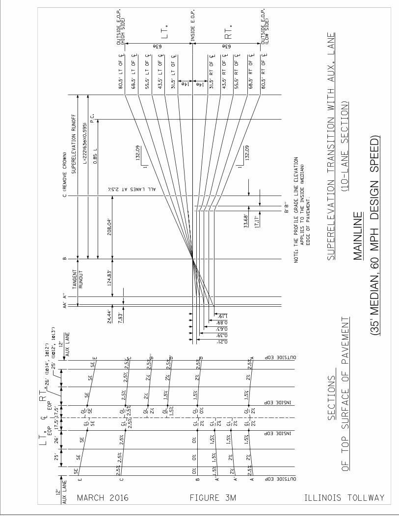
OF
TO
P S
UR
FA
CE
OF
PA
VE
ME
NT
SE
CT
ION
S
(35' M
ED
IAN
, 60 M
PH
DE
SIG
N S
PE
ED
)
MA
INL
INE
(10-L
AN
E S
EC
TIO
N)
SU
PE
RE
LE
VA
TIO
N T
RA
NS
ITIO
N W
ITH
AU
X. L
AN
E
25
'26'
17
.5'1
7.5
'
EO
PE
OP
LT
.R
T.
C L
OUTSIDE EOP
OUTSIDE EOP
INSIDE EOP
INSIDE EOP
AA
A"
B
C
E
B'
B
C
E
GL
GL
GL
GL
GL
1.5
%
1.5
%1.5
%
0%
2%
0%
SE
SE
GL
GL
GL
GL
GL
1.5
%2%
1.5
%2%
2%
1.5
%
SE
SE
2.5
%2.5
%
0%
1.5
%
GL
1.5
%2%
2%
A'
2.5
%
2.5
%2.5
%2.5
%2.5
%2.5
%2.5
%
2.5
%
B"
2.5
%2%
GL
2%
SE
SE
AU
X L
AN
E
12
'
AU
X L
AN
E
12
' 0.21'
0.39'
0.63'
0.89'
1.19'
(HIG
H S
IDE
)O
UT
SID
E E
.O.P
.
LT
.
IN
SID
E E
.O.P
.
63e (LO
W S
IDE
)O
UT
SID
E E
.O.P
.
63e
RU
NO
UT
TA
NG
EN
T
7.9
3'
24.4
4'AA
'A
"B
SU
PE
RE
LE
VA
TIO
N R
UN
OF
F
L=
22
2(6
3e)(0
.59
5)
0.8
5 L
E
DG
E O
F P
AV
EM
EN
T.
A
PP
LIE
S T
O T
HE
IN
SID
E (
ME
DIA
N)
NO
TE
: T
HE
PR
OF
ILE
GR
AD
E L
INE
EL
EV
AT
ION
14e 14e
L3
1.5
' L
T O
F C
L4
3.5
' L
T O
F C
L5
5.5
' L
T O
F C
L68.5
' L
T O
F C
L80.5
' L
T O
F C
L31.5
' R
T O
F C
L4
3.5
' R
T O
F C
L5
5.5
' R
T O
F C
L6
8.5
' R
T O
F C
L80.5
' R
T O
F C
B"
B'
17
.17
'
33
.68
'
ALL LANES AT 2.5%
P.C
.
12
4.8
3'
20
8.0
4'
1
132.0
9
26' (1@
14', 1
@12')
25' (1@
12', 1
@13')
C (
RE
MO
VE
CR
OW
N)
FIGURE 3M ILLINOIS TOLLWAY
2%
2%
2%
2%
2%
0%
1.5
%
2%
2.5
%2.5
%
SE
SE
MARCH 2016
1
132.0
9
RT
.
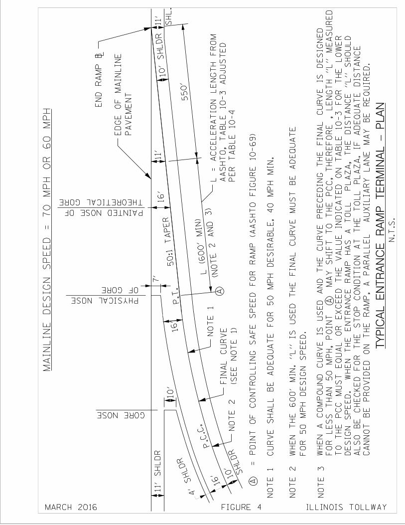
550'
50:1 TAPER
P.T.
P.C.C.
A
A
TY
PIC
AL
EN
TR
AN
CE
RA
MP
TE
RM
INA
L -
PL
AN
16'
16'
10'
SHLDR
11
' S
HL
DR
FIGURE 4
4'
SHLDR
PE
R T
AB
LE
10-4
AA
SH
TO
, T
AB
LE
10
-3 A
DJU
ST
ED
L =
AC
CE
LE
RA
TIO
N L
EN
GT
H F
RO
M
= P
OIN
T O
F C
ON
TR
OL
LIN
G S
AF
E S
PE
ED
FO
R R
AM
P (
AA
SH
TO
FIG
UR
E 1
0-6
9)
N.T
.S.
MA
IN
LIN
E D
ES
IG
N S
PE
ED
= 7
0 M
PH
OR
60 M
PH
10'
7'
SH
L.
11'
ILLINOIS TOLLWAYMARCH 2016
11'
(NOTE 2 AND 3)
EN
D R
AM
P \
(S
EE
NO
TE
1)
FIN
AL
CU
RV
E
NO
TE
1
NO
TE
2
NO
TE
2
NO
TE
3
CU
RV
E S
HA
LL
BE
AD
EQ
UA
TE
FO
R 5
0 M
PH
DE
SIR
AB
LE
, 4
0 M
PH
MIN
.N
OT
E 1
FO
R 5
0 M
PH
DE
SIG
N S
PE
ED
.
WH
EN
TH
E 6
00' M
IN
. "L
" I
S U
SE
D T
HE
FIN
AL
CU
RV
E M
US
T B
E A
DE
QU
AT
E
GORE NOSE
PA
VE
ME
NT
ED
GE
OF
MA
INL
INE
SHLDR
10'
OF GORE
PHYSICAL NOSE
THEORETICAL GORE
PAINTED NOSE OF
CA
NN
OT
BE
PR
OV
IDE
D O
N T
HE
RA
MP
, A
PA
RA
LL
EL
A
UX
ILIA
RY
LA
NE
MA
Y B
E R
EQ
UIR
ED
.
AL
SO
BE
CH
EC
KE
D F
OR
TH
E S
TO
P C
ON
DIT
ION
AT
TH
E T
OL
L P
LA
ZA
. IF
AD
EQ
UA
TE
DIS
TA
NC
E
DE
SIG
N S
PE
ED
. W
HE
N T
HE
EN
TR
AN
CE
RA
MP
HA
S A
TO
LL
P
LA
ZA
, T
HE
DIS
TA
NC
E "
L" S
HO
UL
D
TO
TH
E P
CC
MU
ST
EQ
UA
L O
R E
XC
EE
D T
HE
VA
LU
E I
ND
ICA
TE
D O
N T
AB
LE
10
-3 F
OR
TH
E L
OW
ER
FO
R L
ES
S T
HA
N 5
0 M
PH
, P
OIN
T A
M
AY
SH
IF
T T
O T
HE
PC
C, T
HE
RE
FO
RE
, L
EN
GT
H "
L" M
EA
SU
RE
D
WH
EN
A C
OM
PO
UN
D C
UR
VE
IS
US
ED
AN
D T
HE
CU
RV
E P
RE
CE
DIN
G T
HE
FIN
AL
CU
RV
E I
S D
ES
IGN
ED
16'
L (6
00'
MIN)
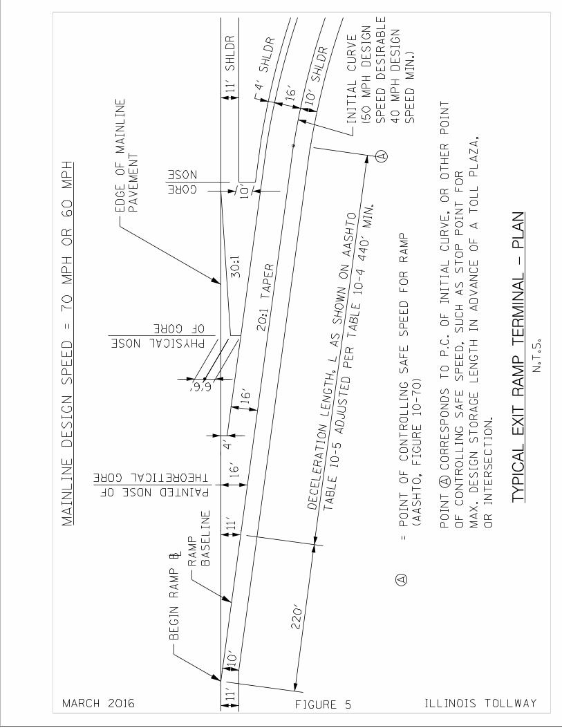
A
220'
6' 6'
20:1 TAPER
A
TY
PIC
AL
EX
IT R
AM
P T
ER
MIN
AL
- P
LA
N
16'
4'
SHLDR
10'
SHLDR
16'
10'
30:1
(A
AS
HT
O,
FIG
UR
E 1
0-7
0)
= P
OIN
T O
F C
ON
TR
OL
LIN
G S
AF
E S
PE
ED
FO
R R
AM
P
N.T
.S.
MA
IN
LIN
E D
ES
IG
N S
PE
ED
= 7
0 M
PH
OR
60 M
PH
10
'
11' S
HL
DR
11'
11'
TABLE 10-5 ADJUSTED PER TABLE 10-4 440'
MIN.
DECELERATION LENGTH,
L AS SHO
WN ON AASHTO
OR
IN
TE
RS
EC
TIO
N.
MA
X. D
ES
IGN
ST
OR
AG
E L
EN
GT
H I
N A
DV
AN
CE
OF
A T
OL
L P
LA
ZA
,
OF
CO
NT
RO
LL
ING
SA
FE
SP
EE
D,
SU
CH
AS
ST
OP
PO
INT
FO
R
PO
INT
A C
OR
RE
SP
ON
DS
TO
P.C
. O
F I
NIT
IAL
CU
RV
E, O
R O
TH
ER
PO
INT
4'
FIGURE 5
BE
GIN
RA
MP
\
BA
SE
LIN
E
RA
MP
SP
EE
D M
IN.)
40 M
PH
DE
SIG
N
SP
EE
D D
ES
IRA
BL
E
(50 M
PH
DE
SIG
N
INIT
IAL
CU
RV
E
OF GORE
PHYSICAL NOSE
PA
VE
ME
NT
ED
GE
OF
MA
INL
INE
NOSE
GORE
MARCH 2016 ILLINOIS TOLLWAY
THEORETICAL GORE
PAINTED NOSE OF 16'
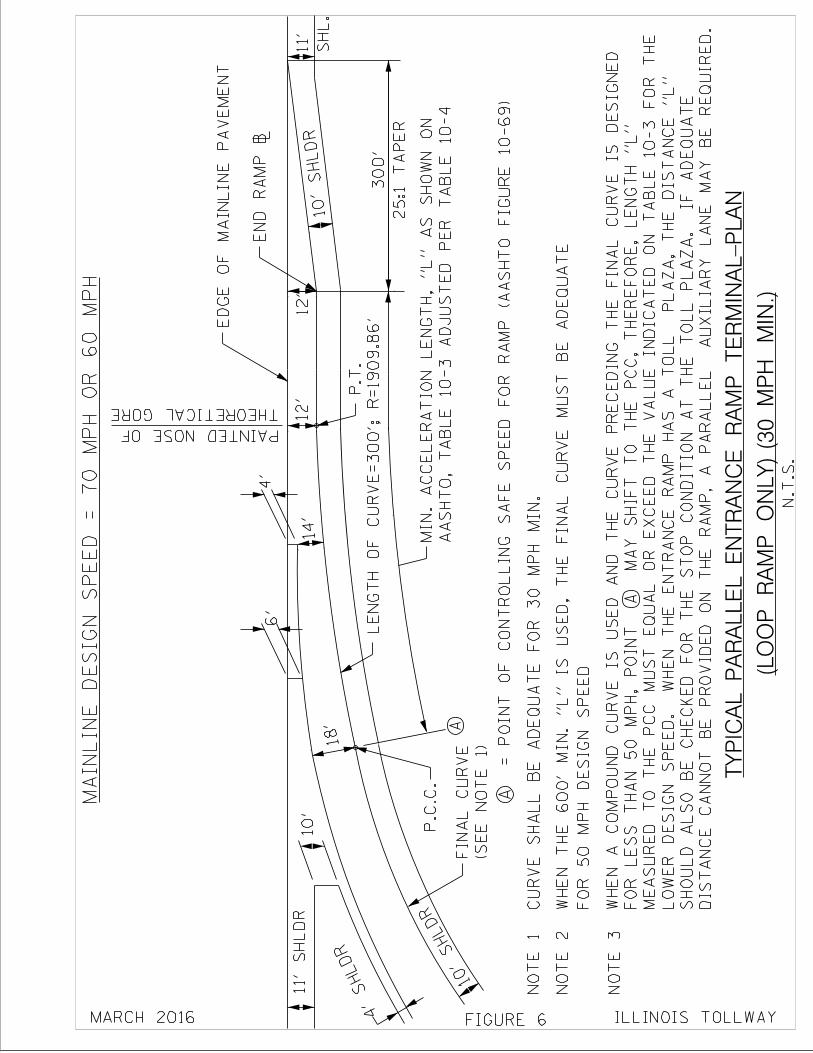
A
18'
14'
10'
SHLDR
4'
SHLDR
10'
SHLDR
11
' S
HL
DR
25
:1 T
AP
ER
30
0'
S
HL
.
11'
A=
PO
INT
OF
CO
NT
RO
LL
ING
SA
FE
SP
EE
D F
OR
RA
MP
(A
AS
HT
O F
IGU
RE
10-6
9)
N.T
.S.
MA
IN
LIN
E D
ES
IG
N S
PE
ED
= 7
0 M
PH
OR
60 M
PH
FO
R 5
0 M
PH
DE
SIG
N S
PE
ED
WH
EN
TH
E 6
00' M
IN
. "L
" I
S U
SE
D, T
HE
FIN
AL
CU
RV
E M
US
T B
E A
DE
QU
AT
E
4'
FIGURE 6
6
'
12'
12'
10
'
P.T
.
LE
NG
TH
OF
CU
RV
E=
300'; R
=1909.8
6'
P.C
.C.
ED
GE
OF
MA
INL
INE
PA
VE
ME
NT
EN
D R
AM
P \
(S
EE
NO
TE
1)
FIN
AL
CU
RV
E
AA
SH
TO
, T
AB
LE
10
-3 A
DJU
ST
ED
PE
R T
AB
LE
10
-4
MIN
. A
CC
EL
ER
AT
ION
LE
NG
TH
, "L
" A
S S
HO
WN
ON
CU
RV
E S
HA
LL
BE
AD
EQ
UA
TE
FO
R 3
0 M
PH
MIN
.N
OT
E 1
NO
TE
2
NO
TE
3
(LO
OP
RA
MP
ON
LY
) (3
0 M
PH
MIN
.)
TY
PIC
AL
PA
RA
LL
EL
EN
TR
AN
CE
RA
MP
TE
RM
INA
L-P
LA
N
MARCH 2016 ILLINOIS TOLLWAY
THEORETICAL GORE
PAINTED NOSE OF
DIS
TA
NC
E C
AN
NO
T B
E P
RO
VID
ED
ON
TH
E R
AM
P, A
PA
RA
LL
EL
A
UX
ILIA
RY
LA
NE
MA
Y B
E R
EQ
UIR
ED
.
SH
OU
LD
AL
SO
BE
CH
EC
KE
D F
OR
TH
E S
TO
P C
ON
DIT
ION
AT
TH
E T
OL
L P
LA
ZA
. I
F A
DE
QU
AT
E
LO
WE
R D
ES
IGN
SP
EE
D. W
HE
N T
HE
EN
TR
AN
CE
RA
MP
HA
S A
TO
LL
P
LA
ZA
, T
HE
DIS
TA
NC
E "
L"
ME
AS
UR
ED
TO
TH
E P
CC
MU
ST
EQ
UA
L O
R E
XC
EE
D T
HE
VA
LU
E I
ND
ICA
TE
D O
N T
AB
LE
10-3
FO
R T
HE
FO
R L
ES
S T
HA
N 5
0 M
PH
, P
OIN
T A
M
AY
SH
IF
T T
O T
HE
PC
C, T
HE
RE
FO
RE
, L
EN
GT
H "
L"
WH
EN
A C
OM
PO
UN
D C
UR
VE
IS
US
ED
AN
D T
HE
CU
RV
E P
RE
CE
DIN
G T
HE
FIN
AL
CU
RV
E I
S D
ES
IGN
ED
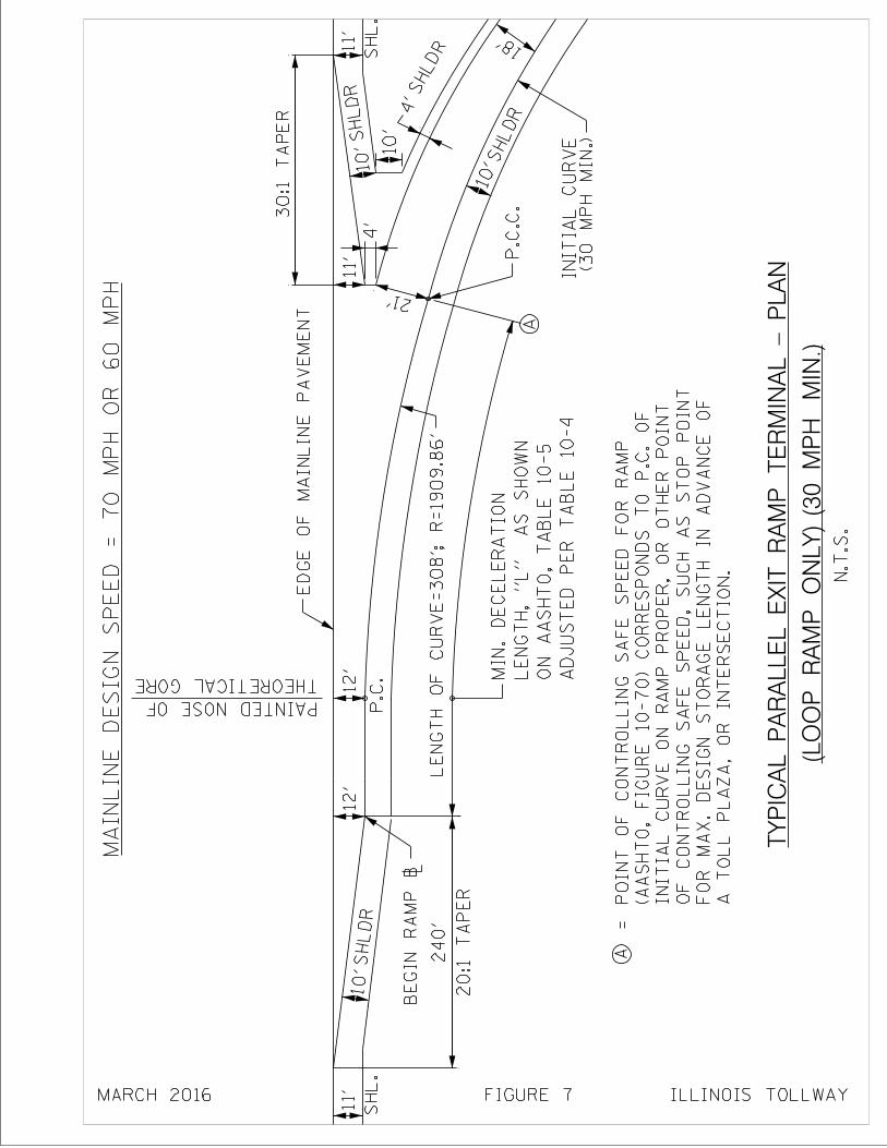
A
30:1
TA
PE
R
1
1'
10'
4'
10'
SH
L.
SHLDR
SHLDR
SHLDR
10'
SH
L.
1
1'
SHLDR
A
20
:1 T
AP
ER
24
0'
N.T
.S.
MA
IN
LIN
E D
ES
IG
N S
PE
ED
= 7
0 M
PH
OR
60 M
PH 21'
18'
AD
JU
ST
ED
PE
R T
AB
LE
10-4
ON
AA
SH
TO
, T
AB
LE
10-5
LE
NG
TH
, "L
" A
S S
HO
WN
MIN
. D
EC
EL
ER
AT
ION
ILLINOIS TOLLWAYFIGURE 7MARCH 2016
10'
4
'
11'
12'
12'
P.C
.C.
(30 M
PH
MIN
.)IN
ITIA
L C
UR
VE
A T
OL
L P
LA
ZA
, O
R I
NT
ER
SE
CT
ION
.
FO
R M
AX
. D
ES
IGN
ST
OR
AG
E L
EN
GT
H I
N A
DV
AN
CE
OF
OF
CO
NT
RO
LL
ING
SA
FE
SP
EE
D,
SU
CH
AS
ST
OP
PO
INT
INIT
IAL
CU
RV
E O
N R
AM
P P
RO
PE
R, O
R O
TH
ER
PO
INT
(A
AS
HT
O,
FIG
UR
E 1
0-7
0) C
OR
RE
SP
ON
DS
TO
P.C
. O
F
PO
INT
OF
CO
NT
RO
LL
ING
SA
FE
SP
EE
D F
OR
RA
MP
=
(LO
OP
RA
MP
ON
LY
) (3
0 M
PH
MIN
.)
TY
PIC
AL
PA
RA
LL
EL
EX
IT R
AM
P T
ER
MIN
AL
- P
LA
N
BE
GIN
RA
MP
\
LE
NG
TH
OF
CU
RV
E=
30
8'; R
=1
90
9.8
6'
ED
GE
OF
MA
INL
INE
PA
VE
ME
NT
P.C
.THEORETICAL GORE
PAINTED NOSE OF
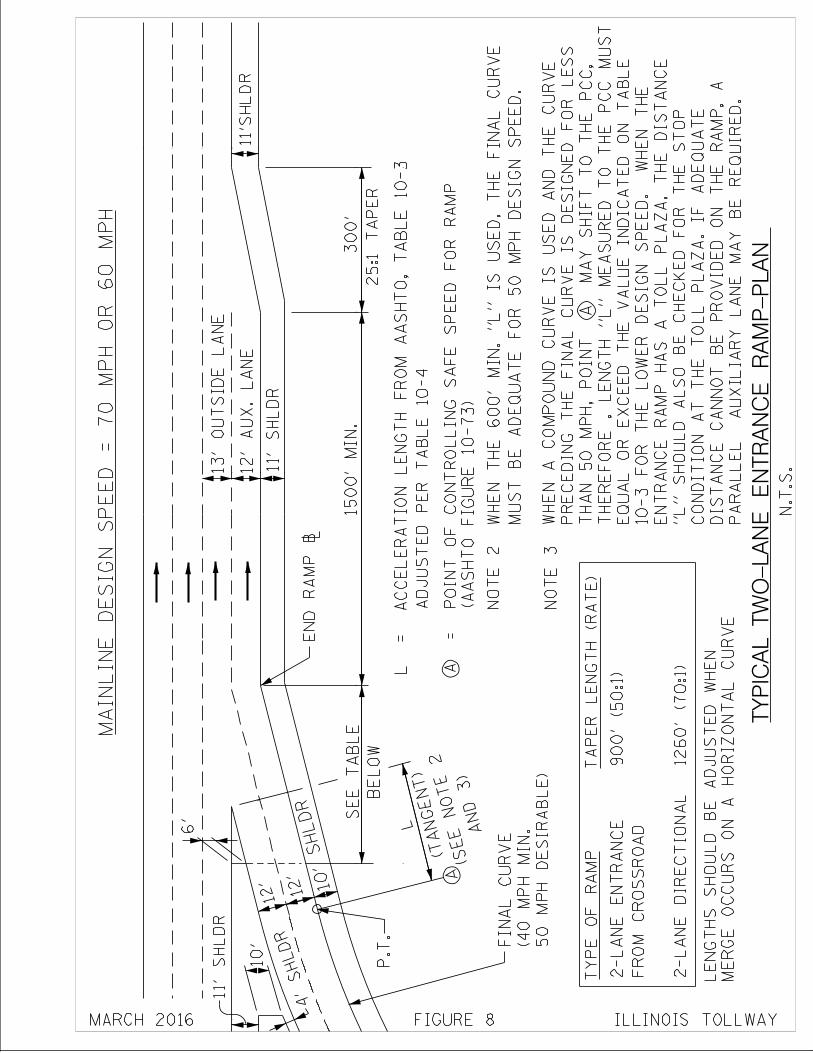
1
1'S
HL
DR
12' A
12'
6'
10
'
11
' S
HL
DR
4'
SHLDR
TY
PIC
AL
TW
O-L
AN
E E
NT
RA
NC
E R
AM
P-P
LA
N
A
DJU
ST
ED
PE
R T
AB
LE
10-4
L =
A
CC
EL
ER
AT
ION
LE
NG
TH
FR
OM
AA
SH
TO
, T
AB
LE
10-3
(A
AS
HT
O F
IG
UR
E 1
0-7
3)
A
=
PO
IN
T O
F C
ON
TR
OL
LIN
G S
AF
E S
PE
ED
FO
R R
AM
P
N.T
.S.
1
3' O
UT
SID
E L
AN
E
1
2' A
UX
. L
AN
E
TY
PE
OF
RA
MP
TA
PE
R L
EN
GT
H (
RA
TE
)
2-L
AN
E D
IRE
CT
ION
AL
FR
OM
CR
OS
SR
OA
D
2-L
AN
E E
NT
RA
NC
E
12
60
' (7
0:1
)
90
0' (5
0:1
)
ME
RG
E O
CC
UR
S O
N A
HO
RIZ
ON
TA
L C
UR
VE
LE
NG
TH
S S
HO
UL
D B
E A
DJU
ST
ED
WH
EN
MA
IN
LIN
E D
ES
IG
N S
PE
ED
= 7
0 M
PH
OR
60 M
PH
11' S
HL
DR
BE
LO
W
SE
E T
AB
LE
L
P.T
.
FIGURE 8 ILLINOIS TOLLWAYMARCH 2016
10'
SHLDR
50
MP
H D
ES
IRA
BL
E)
(4
0 M
PH
MIN
.
FIN
AL
CU
RV
E
1500' M
IN
.300'
25
:1 T
AP
ER
AND 3)
(SEE NOTE 2
(TANGENT)
NO
TE
2
NO
TE
3
MU
ST
BE
AD
EQ
UA
TE
FO
R 5
0 M
PH
DE
SIG
N S
PE
ED
.
WH
EN
TH
E 6
00
' M
IN
. "L
" I
S U
SE
D,
TH
E F
IN
AL
CU
RV
E
PA
RA
LL
EL
A
UX
ILIA
RY
LA
NE
MA
Y B
E R
EQ
UIR
ED
.
DIS
TA
NC
E C
AN
NO
T B
E P
RO
VID
ED
ON
TH
E R
AM
P, A
CO
ND
ITIO
N A
T T
HE
TO
LL
PL
AZ
A. IF
AD
EQ
UA
TE
"L
" S
HO
UL
D A
LS
O B
E C
HE
CK
ED
FO
R T
HE
ST
OP
EN
TR
AN
CE
RA
MP
HA
S A
TO
LL
PL
AZ
A, T
HE
DIS
TA
NC
E
10-3 F
OR
TH
E L
OW
ER
DE
SIG
N S
PE
ED
. W
HE
N T
HE
EQ
UA
L O
R E
XC
EE
D T
HE
VA
LU
E I
ND
ICA
TE
D O
N T
AB
LE
TH
ER
EF
OR
E ,
LE
NG
TH
"L
" M
EA
SU
RE
D T
O T
HE
PC
C M
US
T
TH
AN
50 M
PH
, P
OIN
T A
M
AY
SH
IF
T T
O T
HE
PC
C,
PR
EC
ED
ING
TH
E F
INA
L C
UR
VE
IS
DE
SIG
NE
D F
OR
LE
SS
WH
EN
A C
OM
PO
UN
D C
UR
VE
IS
US
ED
AN
D T
HE
CU
RV
E
EN
D R
AM
P \
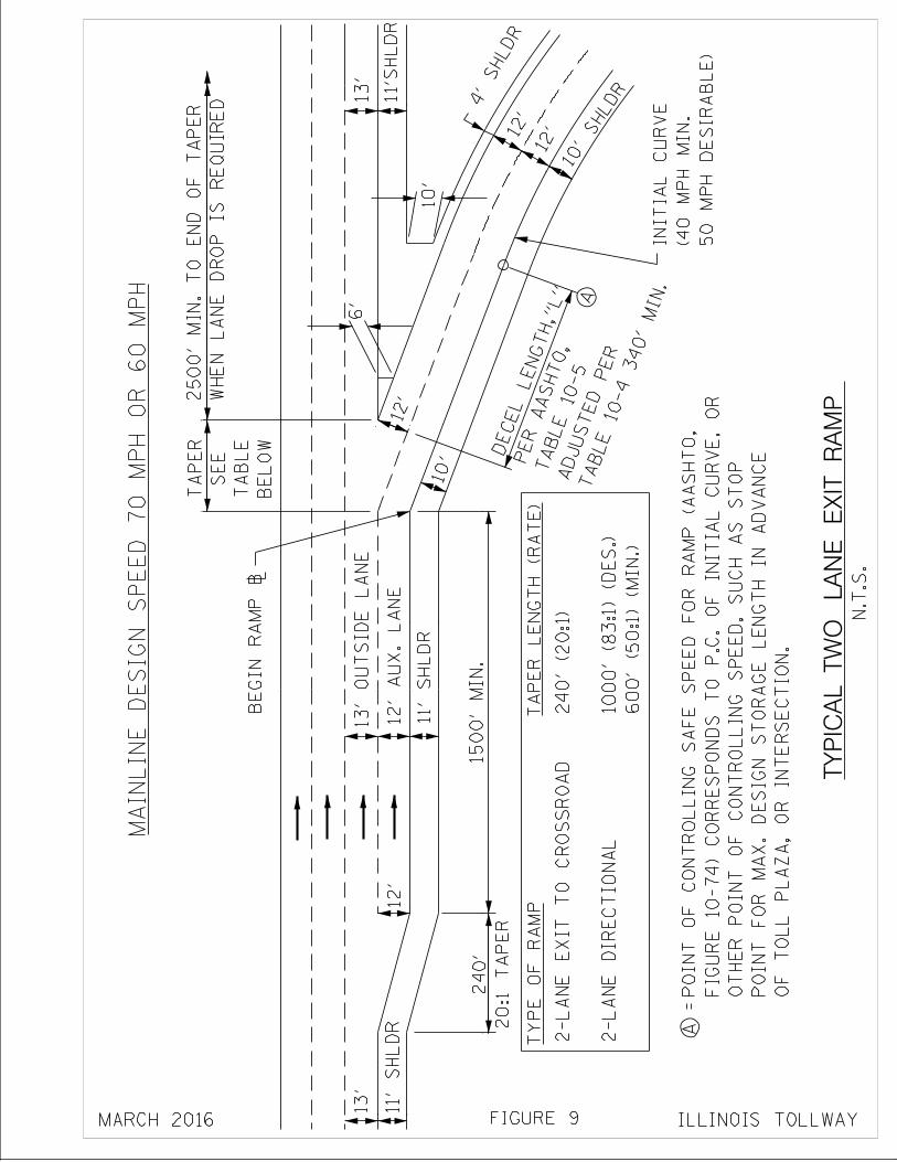
12'
12'
10'
SHLDR
MA
INL
INE
DE
SIG
N S
PE
ED
70
MP
H O
R 6
0 M
PH
11'S
HL
DR
TY
PE
OF
RA
MP
A
1500' M
IN
.
A =
6
'
12'
1
0'
TY
PIC
AL
TW
O L
AN
E E
XIT
RA
MP
4'
SHLDR
10'
11
' S
HL
DR
BE
LO
W
TA
BL
E
SE
E
TA
PE
R
13'
TABLE 10-4 340'
MIN.
ADJUSTED PER
TABLE 10-5
PER AASHTO,
DECEL LENGTH,"
L"
OF
TO
LL
PL
AZ
A, O
R I
NT
ER
SE
CT
ION
.
PO
INT
FO
R M
AX
. D
ES
IGN
ST
OR
AG
E L
EN
GT
H I
N A
DV
AN
CE
OT
HE
R P
OIN
T O
F C
ON
TR
OL
LIN
G S
PE
ED
, S
UC
H A
S S
TO
P
FIG
UR
E 1
0-74) C
OR
RE
SP
ON
DS
TO
P.C
. O
F I
NIT
IA
L C
UR
VE
, O
R
PO
INT
OF
CO
NT
RO
LL
ING
SA
FE
SP
EE
D F
OR
RA
MP
(A
AS
HT
O,
12'
20
:1 T
AP
ER
240'
12' A
UX
. L
AN
E
13
' O
UT
SID
E L
AN
E
2-L
AN
E D
IRE
CT
ION
AL
2-L
AN
E E
XIT
TO
CR
OS
SR
OA
D
TA
PE
R L
EN
GT
H (
RA
TE
)
N.T
.S.
FIGURE 9 ILLINOIS TOLLWAYMARCH 2016
WH
EN
LA
NE
DR
OP
IS
RE
QU
IRE
D
2500' M
IN
. T
O E
ND
OF
TA
PE
R
13'
11
' S
HL
DR
BE
GIN
RA
MP
\
50
MP
H D
ES
IRA
BL
E)
(4
0 M
PH
MIN
.
INIT
IAL
CU
RV
E
60
0' (5
0:1
) (
MIN
.)
1000' (83:1
) (
DE
S.)
24
0' (2
0:1
)
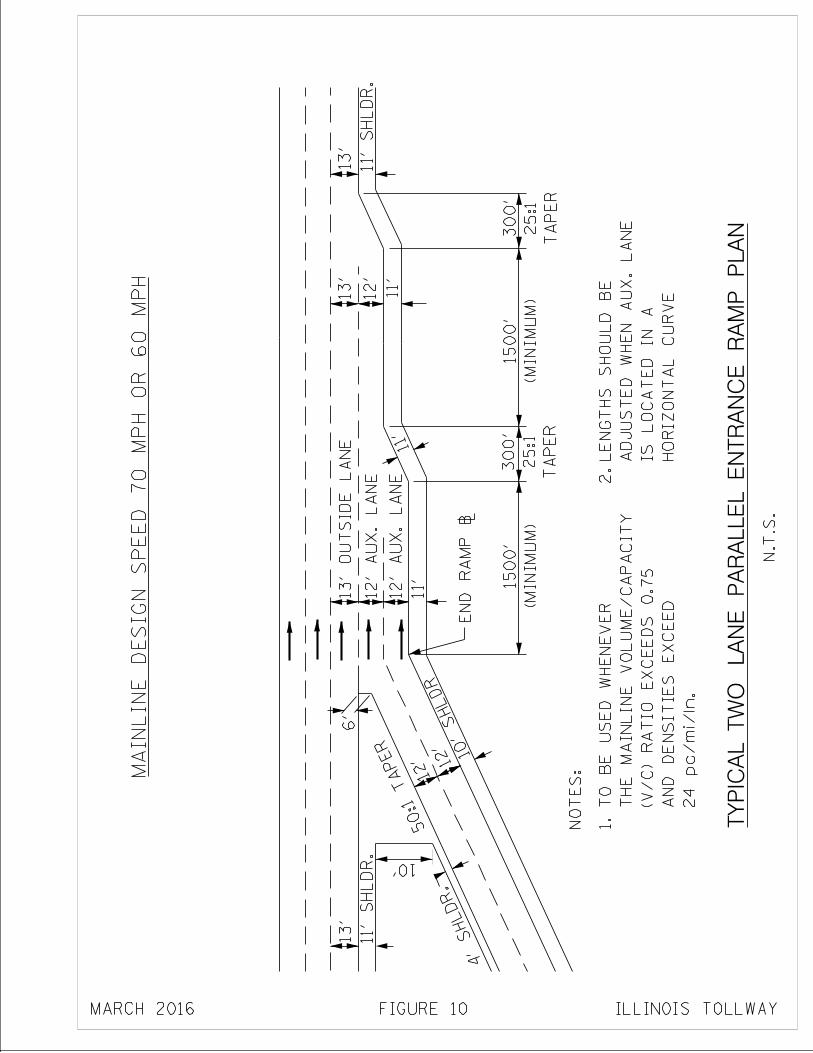
11'
12'
12'
6'
4'
SHLDR.
11'
TY
PIC
AL
TW
O L
AN
E P
AR
AL
LE
L E
NT
RA
NC
E R
AM
P P
LA
N
13'
13'
12'
13'
50:1 TAPER
TA
PE
R
25:1
300'
TA
PE
R
25:1
300'
(MIN
IMU
M)
15
00
'
(MIN
IMU
M)
15
00
'
13
' O
UT
SID
E L
AN
E
11'
12
' A
UX
. L
AN
E
12
' A
UX
. L
AN
E
N.T
.S.
NO
TE
S:
24
pc/m
i/ln
.
AN
D D
EN
SIT
IES
EX
CE
ED
(V
/C) R
AT
IO
EX
CE
ED
S 0
.75
TH
E M
AIN
LIN
E V
OL
UM
E/C
AP
AC
ITY
TO
BE
US
ED
WH
EN
EV
ER
1.
2.
11' S
HL
DR
.
MA
INL
INE
DE
SIG
N S
PE
ED
70
MP
H O
R 6
0 M
PH
HO
RIZ
ON
TA
L C
UR
VE
IS
LO
CA
TE
D I
N A
AD
JU
ST
ED
WH
EN
AU
X. L
AN
E
LE
NG
TH
S S
HO
UL
D B
E
ILLINOIS TOLLWAYFIGURE 10MARCH 2016
EN
D R
AM
P \
10'
SHLDR
10'
11' S
HL
DR
.
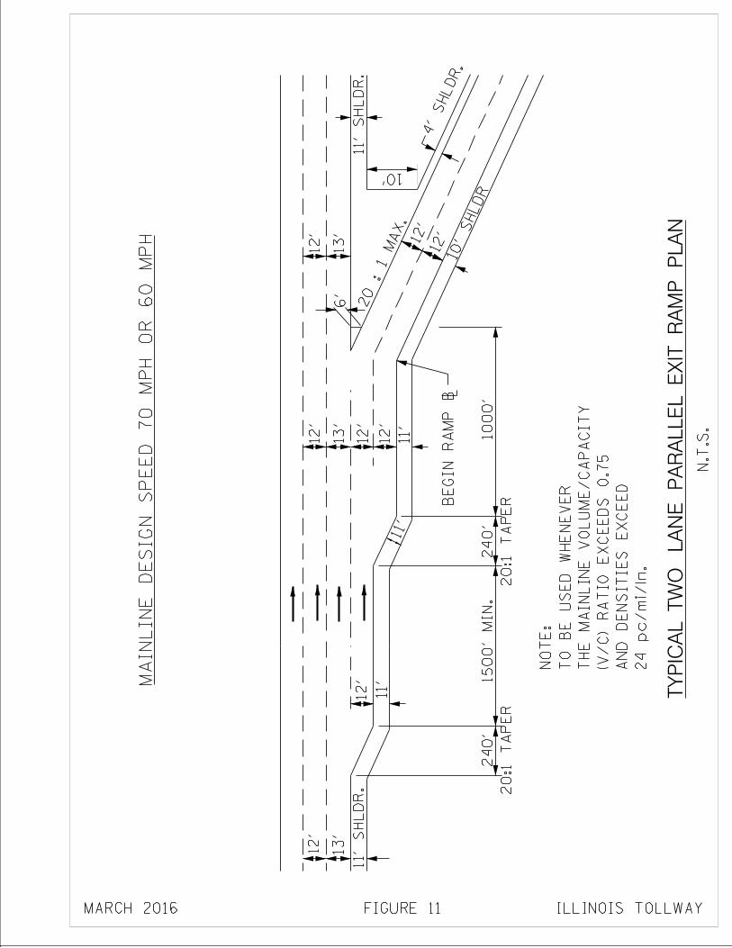
10
00
'
11'
12'12'
6'
11' S
HL
DR
.
11'
11'
20 :
1
MAX.
NO
TE
:
TY
PIC
AL
TW
O L
AN
E P
AR
AL
LE
L E
XIT
RA
MP
PL
AN
24
pc/m
i/ln
.
AN
D D
EN
SIT
IES
EX
CE
ED
(V
/C) R
AT
IO
EX
CE
ED
S 0
.75
TH
E M
AIN
LIN
E V
OL
UM
E/C
AP
AC
ITY
TO
BE
US
ED
WH
EN
EV
ER
12'
13'
12'
20
:1 T
AP
ER
24
0'
20
:1 T
AP
ER
24
0'
12'
13'
12'
12'
12'
13'
N.T
.S.
MA
INL
INE
DE
SIG
N S
PE
ED
70
MP
H O
R 6
0 M
PH
4'
SHLDR.
ILLINOIS TOLLWAYFIGURE 11
11' S
HL
DR
.
1500' M
IN
.
MARCH 2016
10'
SHLDR
BE
GIN
RA
MP
\
10'
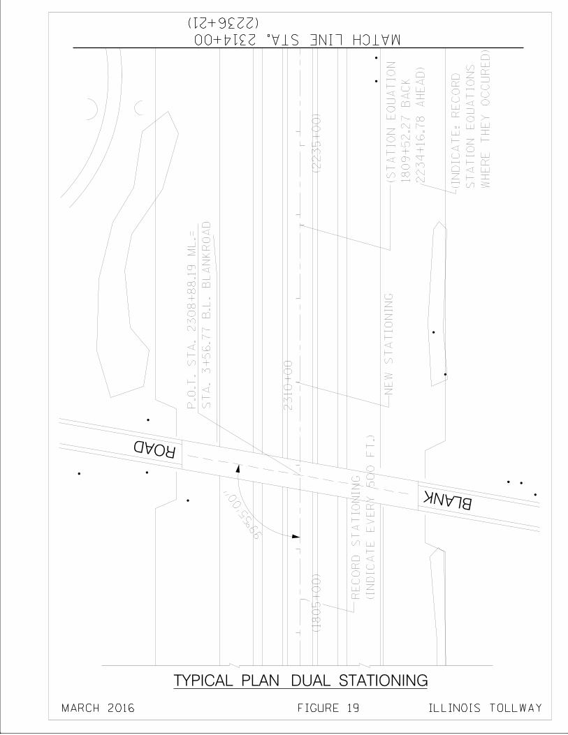
ST
A.
3+
56
.77
B.L
. B
LA
NK
RO
AD
P.O
.T. S
TA
. 2308+
88.1
9 M
L.=
(IN
DIC
AT
E E
VE
RY
50
0 F
T.)
RE
CO
RD
ST
AT
ION
ING
NE
W S
TA
TIO
NIN
G
(2236+21)
MATCH LINE STA. 2314+00
BLANK
ROAD
99°55'0
0"
23
10
+0
0
(1805+
00)
TYPICAL PLAN DUAL STATIONING
(2
23
5+
00
)
22
34
+1
6.7
8 A
HE
AD
)
1809+
52.2
7 B
AC
K
(ST
AT
ION
EQ
UA
TIO
N
WH
ER
E T
HE
Y O
CC
UR
ED
)
ST
AT
ION
EQ
UA
TIO
NS
(IN
DIC
AT
E:
RE
CO
RD
ILLINOIS TOLLWAYFIGURE 19MARCH 2016
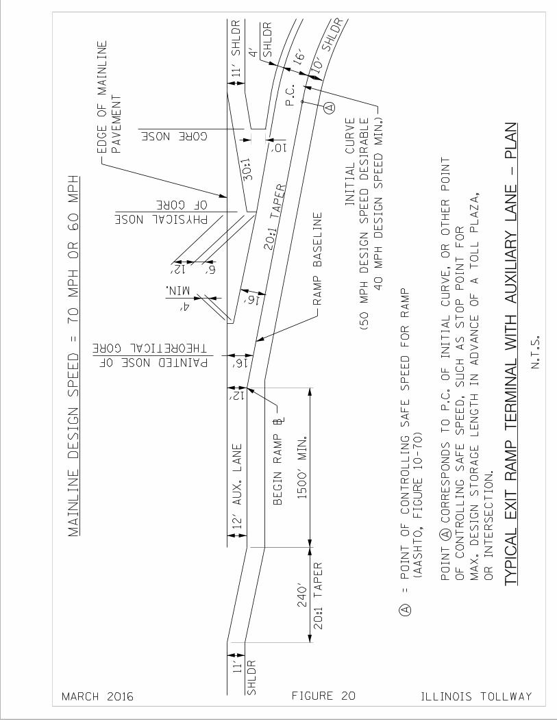
6'12'
MA
IN
LIN
E D
ES
IG
N S
PE
ED
= 7
0 M
PH
OR
60 M
PH
10'
12'
BE
GIN
RA
MP
\
1500' M
IN
.2
40
'
20
:1 T
AP
ER
P.C
.
20:1 TAPER
16'
30:1
11
' S
HL
DR
12
' A
UX
. L
AN
E
MIN.
4' RA
MP
BA
SE
LIN
E
A
(A
AS
HT
O,
FIG
UR
E 1
0-7
0)
= P
OIN
T O
F C
ON
TR
OL
LIN
G S
AF
E S
PE
ED
FO
R R
AM
P
N.T
.S.
OR
IN
TE
RS
EC
TIO
N.
MA
X. D
ES
IGN
ST
OR
AG
E L
EN
GT
H I
N A
DV
AN
CE
OF
A T
OL
L P
LA
ZA
,
OF
CO
NT
RO
LL
ING
SA
FE
SP
EE
D,
SU
CH
AS
ST
OP
PO
INT
FO
R
PO
INT
A C
OR
RE
SP
ON
DS
TO
P.C
. O
F I
NIT
IAL
CU
RV
E, O
R O
TH
ER
PO
INT
TY
PIC
AL
EX
IT R
AM
P T
ER
MIN
AL
WIT
H A
UX
ILIA
RY
LA
NE
- P
LA
N
FIGURE 20
10'
SHLDR
16'SH
LD
R
4'
A
40
MP
H D
ES
IG
N S
PE
ED
MIN
.)
(50 M
PH
DE
SIG
N S
PE
ED
DE
SIR
AB
LE
INIT
IAL
CU
RV
E
SH
LD
R
11'
OF GORE
PHYSICAL NOSE
GORE NOSE
THEORETICAL GORE
PAINTED NOSE OF
PA
VE
ME
NT
ED
GE
OF
MA
INL
INE
MARCH 2016 ILLINOIS TOLLWAY
16'
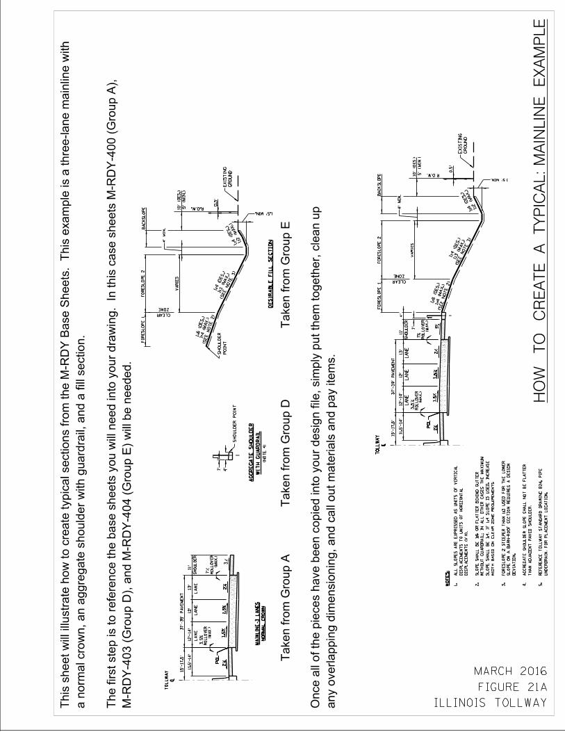
Tak
en
fro
m G
rou
p A
Tak
en
fro
m G
rou
p D
Tak
en
fro
m G
rou
p E
HO
W T
O C
RE
AT
E A
TY
PIC
AL
: M
AIN
LIN
E E
XA
MP
LE
any o
verl
appin
g d
imensio
nin
g, and c
all
out
mate
rials
and p
ay i
tem
s.
On
ce a
ll o
f th
e p
ieces h
av
e b
een
co
pie
d i
nto
yo
ur
desig
n f
ile,
sim
ply
pu
t th
em
to
geth
er,
cle
an
up
FIGURE 21A
ILLINOIS TOLLWAY
NO
RM
AL
CR
OW
N
MA
INL
INE
-3 L
AN
ES
WIT
H G
UA
RD
RA
IL
AG
GR
EG
AT
E S
HO
UL
DE
R
DE
SIR
AB
LE
FIL
L S
EC
TIO
N
NO
TE
S:
MARCH 2016
LA
NE
PG
LP
GL
2%
~
TO
LL
WA
Y
2%
1.5
%1.5
%
LA
NE
LA
NE
PG
LP
GL
2%
TO
LL
WA
Y
~
2%
1.5
%1.5
%3%
SH
OU
LD
ER
7%
(MA
X.)
(MA
X.)
3.5
%
12'
13'
11'
RO
LL
OV
ER
RO
LL
OV
ER
11.5
'-14'
12
'-1
4'
37'-
39' P
AV
EM
EN
T15'-
17.5
'5
' (M
IN
.)
ZONE
CLEAR
PO
INT
SH
OU
LD
ER
1.5' MIN.
GR
OU
ND
EX
IST
ING
0.5'
10
' (D
ES
.)V
AR
IES
4' M
IN
.
R.O.W.
(SEE NOTE 2)
1:4 (M
AX.)
1:6 (D
ES.)
(SEE NOTE 3)
1:3 (M
AX.)
1:4 (D
ES.)
1:2 (M
AX.)
1:4 (D
ES.)
FO
RE
SL
OP
E 2
FO
RE
SL
OP
E 1
BA
CK
SL
OP
E
1'
4'
(N
OT
E 4
)
LA
NE
PG
LP
GL
2%
~
TO
LL
WA
Y
2%
1.5
%1.5
%
LA
NE
LA
NE
PG
LP
GL
2%
TO
LL
WA
Y
~
2%
1.5
%1.5
%3%
SH
OU
LD
ER
7%
(MA
X.)
(MA
X.)
3.5
%
12'
13'
11'
RO
LL
OV
ER
RO
LL
OV
ER
11.5
'-14'
12
'-1
4'
37'-
39' P
AV
EM
EN
T15'-
17.5
'
5' (M
IN
.)
ZONE
CLEAR
1.5' MIN.
GR
OU
ND
EX
IST
ING
0.5'
10
' (D
ES
.)V
AR
IES
4' M
IN
.
R.O.W.
(SEE NOTE 2)
1:4 (M
AX.)
1:6 (D
ES.)
(SEE NOTE 3)
1:3 (M
AX.)
1:4 (D
ES.)
1:2 (M
AX.)
1:4 (D
ES.)
FO
RE
SL
OP
E 2
FO
RE
SL
OP
E 1
BA
CK
SL
OP
E
1'
4'
M-R
DY
-40
3 (
Gro
up
D),
an
d M
-RD
Y-4
04
(G
rou
p E
) w
ill
be n
eed
ed
.
Th
e f
irst
ste
p i
s t
o r
efe
ren
ce t
he b
ase s
heets
yo
u w
ill
need
in
to y
ou
r d
raw
ing
. I
n t
his
case s
heets
M-R
DY
-40
0 (
Gro
up
A),
a n
orm
al
cro
wn, an a
ggre
gate
should
er
wit
h g
uard
rail
, and a
fil
l secti
on.
This
sheet
wil
l il
lustr
ate
how
to c
reate
typic
al
secti
ons f
rom
the M
-RD
Y B
ase S
heets
. T
his
exam
ple
is a
thre
e-l
ane m
ain
line w
ith
SH
OU
LD
ER
PO
INT
UN
DE
RD
RA
IN, F
OR
PL
AC
EM
EN
T L
OC
AT
ION
.
RE
FE
RE
NC
E T
OL
LW
AY
ST
AN
DA
RD
DR
AW
ING
B24, P
IPE
5.
TH
AN
AD
JA
CE
NT
PA
VE
D S
HO
UL
DE
R.
AG
GR
EG
AT
E S
HO
UL
DE
R S
LO
PE
SH
AL
L N
OT
BE
FL
AT
TE
R
4.
DE
VIA
TIO
N.
SL
OP
E O
N A
BA
RN
-RO
OF
SE
CT
ION
RE
QU
IRE
S A
DE
SIG
N
FO
RE
SL
OP
E 2
ST
EE
PE
R T
HA
N 1
:3 U
SE
D F
OR
TH
E L
OW
ER
3.
WID
TH
BA
SE
D O
N C
LE
AR
ZO
NE
RE
QU
IRE
ME
NT
S.
SL
OP
E S
HA
LL
BE
1:4
. IF
1:4
SL
OP
E I
S U
SE
D, IN
CR
EA
SE
WIT
HO
UT
GU
AR
DR
AIL
; IN
AL
L O
TH
ER
CA
SE
S T
HE
MA
XIM
UM
SL
OP
E S
HA
LL
BE
1:6
OR
FL
AT
TE
R B
EH
IND
GU
TT
ER
2.
DIS
PL
AC
EM
EN
TS
(V
:H).
DIS
PL
AC
EM
EN
TS
TO
UN
ITS
OF
HO
RIZ
ON
TA
L
AL
L S
LO
PE
S A
RE
EX
PR
ES
SE
D A
S U
NIT
S O
F V
ER
TIC
AL
1.
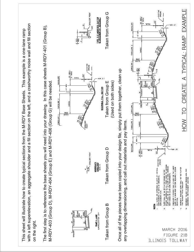
Taken f
rom
Gro
up B
Tak
en
fro
m G
rou
p D
HO
W T
O C
RE
AT
E A
TY
PIC
AL
: R
AM
P E
XA
MP
LE
Tak
en
fro
m G
rou
p G
any o
verl
appin
g d
imensio
nin
g, and c
all
out
mate
rials
and p
ay i
tem
s.
On
ce a
ll o
f th
e p
ieces h
av
e b
een
co
pie
d i
nto
yo
ur
desig
n f
ile,
sim
ply
pu
t th
em
to
geth
er,
cle
an
up
FIGURE 21B
ILLINOIS TOLLWAY
SU
PE
RE
LE
VA
TIO
N L
EF
T
RA
MP
-1 L
AN
ES
HO
UL
DE
R
AG
GR
EG
AT
E
W/C
RA
SH
WO
RT
HY
NO
ISE
WA
LL
TY
PE
G-2
MO
DIF
IED
GU
TT
ER
(Used
on
bo
th s
ides)
Tak
en
fro
m G
rou
p E
MARCH 2016
NO
TE
S:
7%
PA
VE
ME
NT
(MA
X.)
RO
LL
OV
ER
SH
OU
LD
ER
SH
OU
LD
ER
VA
RIE
SSE
SE
4'
16
'10'
PG
L
7%
PA
VE
ME
NT
(MA
X.)
RO
LL
OV
ER
SH
OU
LD
ER
SH
OU
LD
ER
VA
RIE
SSE
SE
4'
16
'10'
PG
L
(N
OT
E 4
)
4'
4'
5' (M
IN
.)
ZONE
CLEAR
1.5' MIN.
GR
OU
ND
EX
IST
ING
0.5
'
10
' (D
ES
.)V
AR
IES
4' M
IN
.
R.O.W.
(SEE NOTE 2)
1:4 (M
AX.)
1:6 (D
ES.)
(SEE NOTE 3)
1:3 (M
AX.)
1:4 (D
ES.)
1:2 (M
AX.)
1:4 (D
ES.)
FO
RE
SL
OP
E 2
FO
RE
SL
OP
E 1
BA
CK
SL
OP
E
5' (M
IN
.)
ZONE
CLEAR
PO
INT
SH
OU
LD
ER
1.5' MIN.
GR
OU
ND
EX
IST
ING
0.5
'
10
' (D
ES
.)V
AR
IES
4' M
IN
.
R.O.W.
(SEE NOTE 2)
1:4 (M
AX.)
1:6 (D
ES.)
(SEE NOTE 3)
1:3 (M
AX.)
1:4 (D
ES.)
1:2 (M
AX.)
1:4 (D
ES.)
FO
RE
SL
OP
E 2
FO
RE
SL
OP
E 1
BA
CK
SL
OP
E
1:1
0
5'
2'
5%
SH
OU
LD
ER
PO
INT
4' M
IN
.
6' D
ES
.
1:1
0
5'
2'
5%
4' M
IN
.
6' D
ES
.
5' (M
IN
.)
ZONE
CLEAR
1.5' MIN.
GR
OU
ND
EX
IST
ING
0.5
'
10
' (D
ES
.)V
AR
IES
4' M
IN
.
R.O.W.
(SEE NOTE 2)
1:4 (M
AX.)
1:6 (D
ES.)
(SEE NOTE 3)
1:3 (M
AX.)
1:4 (D
ES.)
1:2 (M
AX.)
1:4 (D
ES.)
FO
RE
SL
OP
E 2
FO
RE
SL
OP
E 1
BA
CK
SL
OP
E
DE
SIR
AB
LE
FIL
L S
EC
TIO
N
M-R
DY
-403 (
Gro
up D
), M
-RD
Y-4
04 (
Gro
up E
) and M
-RD
Y-4
06 (
Gro
up G
) w
ill
be n
eeded.
Th
e f
irst
ste
p i
s t
o r
efe
ren
ce t
he b
ase s
heets
yo
u w
ill
need
in
to y
ou
r d
raw
ing
. I
n t
his
case s
heets
M-R
DY
-40
1 (
Gro
up
B),
on t
he r
ight.
wit
h a
left
su
pere
lev
ati
on
, an
ag
gre
gate
sh
ou
lder
an
d a
fil
l secti
on
on
th
e l
eft
, an
d a
cra
sh
wo
rth
y n
ois
e w
all
an
d f
ill
secti
on
This
sheet
wil
l il
lustr
ate
how
to c
reate
typic
al
secti
ons f
rom
the M
-RD
Y B
ase S
heets
. T
his
exam
ple
is a
one-l
ane r
am
p
SH
OU
LD
ER
PO
INT
UN
DE
RD
RA
IN, F
OR
PL
AC
EM
EN
T L
OC
AT
ION
.
RE
FE
RE
NC
E T
OL
LW
AY
ST
AN
DA
RD
DR
AW
ING
B24, P
IPE
5.
TH
AN
AD
JA
CE
NT
PA
VE
D S
HO
UL
DE
R.
AG
GR
EG
AT
E S
HO
UL
DE
R S
LO
PE
SH
AL
L N
OT
BE
FL
AT
TE
R
4.
DE
VIA
TIO
N.
SL
OP
E O
N A
BA
RN
-RO
OF
SE
CT
ION
RE
QU
IRE
S A
DE
SIG
N
FO
RE
SL
OP
E 2
ST
EE
PE
R T
HA
N 1
:3 U
SE
D F
OR
TH
E L
OW
ER
3.
WID
TH
BA
SE
D O
N C
LE
AR
ZO
NE
RE
QU
IRE
ME
NT
S.
SL
OP
E S
HA
LL
BE
1:4
. IF
1:4
SL
OP
E I
S U
SE
D, IN
CR
EA
SE
WIT
HO
UT
GU
AR
DR
AIL
; IN
AL
L O
TH
ER
CA
SE
S T
HE
MA
XIM
UM
SL
OP
E S
HA
LL
BE
1:6
OR
FL
AT
TE
R B
EH
IND
GU
TT
ER
2.
DIS
PL
AC
EM
EN
TS
(V
:H).
DIS
PL
AC
EM
EN
TS
TO
UN
ITS
OF
HO
RIZ
ON
TA
L
AL
L S
LO
PE
S A
RE
EX
PR
ES
SE
D A
S U
NIT
S O
F V
ER
TIC
AL
1.
ROADWAY DESIGN CRITERIA
March 2016 Illinois Tollway
APPENDIX A Illinois Tollway, Interchange and Roadway Cost Sharing Policy
http://www.illinoistollway.com/about-the-tollway/rules-regulations-and-policies/interchange-and-cost-sharing-policy