Roadshow Update V2019R1 - cadfem.net
190
© CADFEM (Suisse) AG, 2019 Roadshow Update V2019R1 Joël Grognuz, Thomas Menouillard, Lionel Wilhelm Aniko Raika, Roberto Rossetti CADFEM (Suisse) AG
Transcript of Roadshow Update V2019R1 - cadfem.net
© CADFEM (Suisse) AG, 2019
Roadshow Update V2019R1
Joël Grognuz, Thomas Menouillard, Lionel Wilhelm
Aniko Raika, Roberto Rossetti
CADFEM (Suisse) AG

© CADFEM (Suisse) AG, 2019
Agenda
13:30
Accueil
13:45
SpaceClaim
Discovery Live
Discovery AIM
Mechanical (Environnement)
15:00
Pause
15:30
Mechanical (Analyses)
Workbench Material Designer
Mechanical (Dynamique)
MAPDL
Modèles «Runtime» pour les jumeaux numériques
Autres outils (aperçu rapide)
Conclusion
17:00
© CADFEM (Suisse) AG, 2019
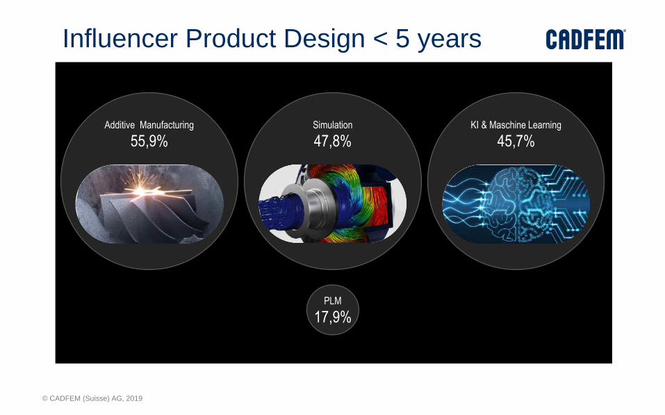
PLM
17,9%
Additive Manufacturing
55,9%KI & Maschine Learning
45,7%Simulation
47,8%
Influencer Product Design < 5 years

© CADFEM (Suisse) AG, 2019
NEWS

© CADFEM (Suisse) AG, 2019
OPTIS

© CADFEM (Suisse) AG, 2019
Where you Find us ? AUTOMOTIVE
AEROSPACE
LIGHTING ELECTRONICS
ENERGY
RESEARCH
ARCHITECTURE
LUXURY
AUTOMATION
MEDICAL
© CADFEM (Suisse) AG, 2019

© CADFEM (Suisse) AG, 2019

© CADFEM (Suisse) AG, 2019
ANSYS Motion

© CADFEM (Suisse) AG, 2019
Design
Optimization
Validation
To
po
log
yo
ptim
iza
tio
n
La
ttice
-Optim
iza
tion
Process Simulation
Design
Optimization
Valididation
Additive Manufacturing and Optimization
© CADFEM (Suisse) AG, 2019
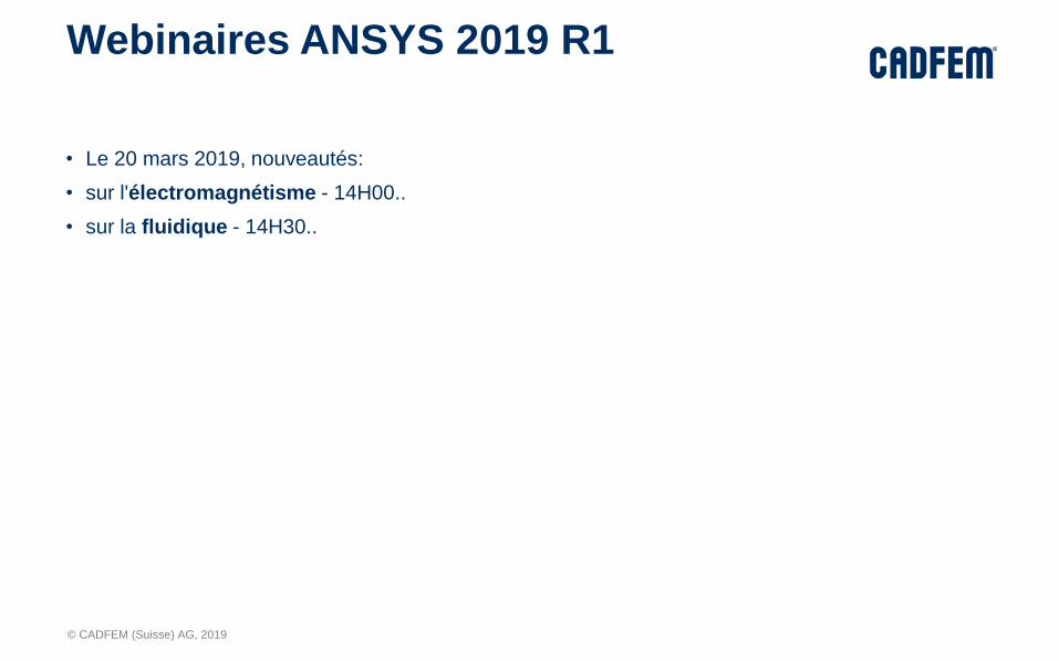
Webinaires ANSYS 2019 R1
• Le 20 mars 2019, nouveautés:
• sur l'électromagnétisme - 14H00..
• sur la fluidique - 14H30..

© CADFEM (Suisse) AG, 2019
• Call for Paper
• Expo HES

© CADFEM (Suisse) AG, 2019
Programme détaillé 1
SpaceClaim :
• Scripting / Journal
• Contraintes dans les esquisses
• Structures en treillis
• Maillage Hexadans SpaceClaim
Discovery Live :
• Etudes paramétriques
• Nouvelles conditions aux limites
• Affichage simultané des résultats de plusieurs champs de vitesses et lignes de courant
• optimisation topologique dans Discovery Live
Discovery AIM :
• Analyse des oscillations issues d’une source aléatoire
• Accélération des calculs structurels non-linéaires
• Variation plus rapide des conditions aux limites par suppression

© CADFEM (Suisse) AG, 2019
Programme détaillé 2
ANSYS Mechanical (environnement) :
• Model sans géométrie, modifications géométriques dans Mechanical, chargement de géométries modifiées facilité
• combinaison de solutions à partir des fichiers csv
• Animation étendues, statistiques d'analyse
• Combinaison de projets workbench
• Aperçu de la future interface 2019 R2
ANSYS Mechanical (analyses) :
• Méthode semi-implicite afin d'éviter les difficultés de convergence
• Optimisation topologique thermique, lissage de STL dans Mechanical
• Additive Manufacturing: plus de paramètres, additive science
• Crack propagation: Prise en compte des charges de pression de température, détection automatique
• Optimisation topologique thermique, structures coque, densité de treillis (lattice), avec contacts non-linéaires
• Lissage automatique des surfaces stl
• HPC: Gestion de la mémoire et parallélisation des contacts
Workbench Material Designer :
• Nouvelles structures de base à treillis prédéfinies
• Cellules unitaires à fibres courtes inégalement réparties
• Granta Design

© CADFEM (Suisse) AG, 2019
Programme détaillé 3
ANSYS Mechanical (Dynamique) :
• Component Mode Synthesis (CMS) pour l'analyse harmonique
• réduire l'espace disque requis.
• Dynamique du rotor
• Noise Vibration Harshness (NVH) : simulation acoustique multiphysique de moteurs électriques
• ANSYS-Motion : nouvelle famille de produits pour la simulation multicorps avancée
• ANSYS LS-DYNA: Prise en compte des charges thermiques ou d'une déformée
MAPDL :
• Fibres thermiques REINF264
• Cables CABLE280
• Viscoélasticité anisotrope dans les analyses piézoélectriques
Modèles "Runtime" pour les jumeaux numériques :
• ROM Builder
Autres outils (aperçu rapide) :
• Fluent: workflow simplifié
• Electromagnétisme: EMI Scanner, NVH, Antennes
• OPTIS: rendus optiques
• EnSight: Postprocessing avancé
• Rocky: DEM

© CADFEM (Suisse) AG, 2019
Discovery 2019 R1
Update

© CADFEM (Suisse) AG, 2019
Outline
• SpaceClaim
• Discovery live
• Discovery AIM (Ansys Integrated Multiphysics)
© CADFEM (Suisse) AG, 2019
SpaceClaim updates
© CADFEM (Suisse) AG, 2019
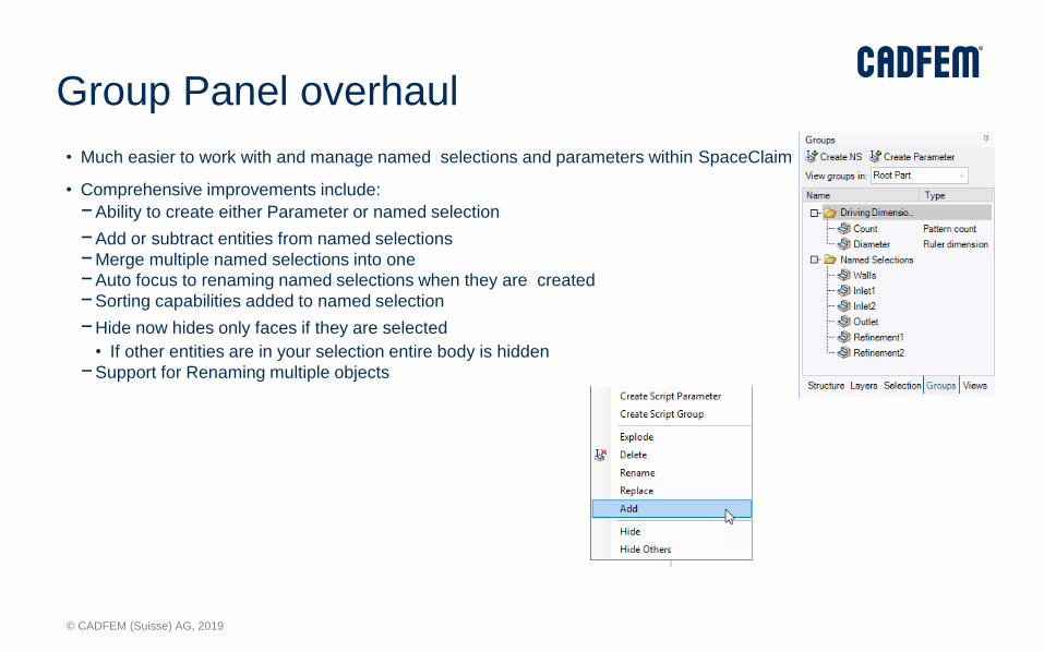
Group Panel overhaul
• Much easier to work with and manage named selections and parameters within SpaceClaim
• Comprehensive improvements include:
−Ability to create either Parameter or named selection
−Add or subtract entities from named selections
−Merge multiple named selections into one
−Auto focus to renaming named selections when they are created
−Sorting capabilities added to named selection
−Hide now hides only faces if they are selected
• If other entities are in your selection entire body is hidden
−Support for Renaming multiple objects
© CADFEM (Suisse) AG, 2019
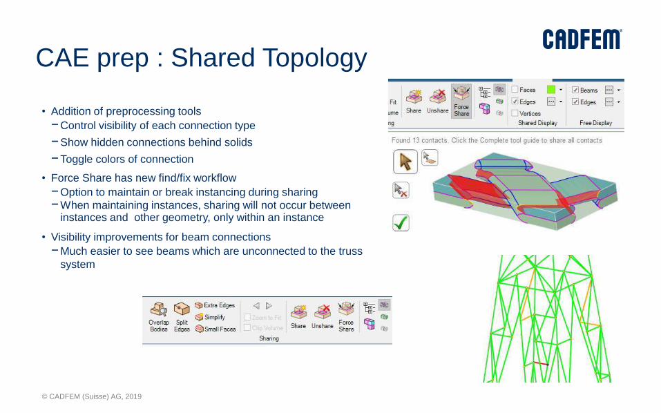
CAE prep : Shared Topology
• Addition of preprocessing tools
−Control visibility of each connection type
−Show hidden connections behind solids
−Toggle colors of connection
• Force Share has new find/fix workflow
−Option to maintain or break instancing during sharing
−When maintaining instances, sharing will not occur between instances and other geometry, only within an instance
• Visibility improvements for beam connections
−Much easier to see beams which are unconnected to the truss
system

© CADFEM (Suisse) AG, 2019
Additive Manufacturing
• New Smoothing Option to preserve volume
−Greatly reduces volume loss when smoothing
−Changed naming convention for existing smoothing methods
• Lattice improvements
−Boundary Conformal lattices
−Remove incomplete lattice members
−Excellent when removing faces and wanting to expose lattices
• Overhang Improvements
−Orientation to reduce overhang
−Create selection out of overhangs
−Useful when creating named selections for simulation of additive process in mechanical

© CADFEM (Suisse) AG, 2019
Core Modeling
• Speed improvements in drawing sheets
−Dimension and note placement speed enhanced
• Layer support for lightweight text in sheet metal
• Scripting support for hole command and share
topology
• Separated selection for vertices vs. points
• XYZ extents when measuring
• Tracelines setup per configuration
• Import Export:
−Support for Keyshot 8
−JT included with Discovery
Live/Standard/Ultimate
−FDM export for Fluent
− Import of Inventor 2019
− Import of Creo 5.0

© CADFEM (Suisse) AG, 2019
Beta Features• Enabled beta option in advanced option
−Allows for more user feedback and
improved communication with
development
• Constraint based Sketching
−Displays over/under constrained sketches
−Add dimensions and sketch constraints
such as tangent, equal distance,
parallel, etc.
• Model replay
−Allows replay of SCDM edits to new
versions of imported geometry
−Bi-directional link from CAD->WB->SCDM
improves parameterization workflow
−Works with most geometry interfaces (not
Catia)
• Guided traceline creation
−Auto detection of coaxial faces for tracelines
−Color coded for easy visualization
© CADFEM (Suisse) AG, 2019
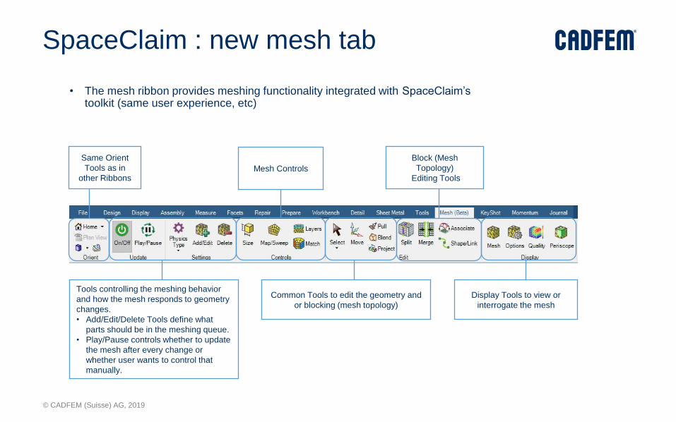
SpaceClaim : new mesh tab
• The mesh ribbon provides meshing functionality integrated with SpaceClaim’stoolkit (same user experience, etc)
Same Orient
Tools as in
other Ribbons
Tools controlling the meshing behavior
and how the mesh responds to geometry
changes.
• Add/Edit/Delete Tools define what
parts should be in the meshing queue.
• Play/Pause controls whether to update
the mesh after every change or
whether user wants to control that
manually.
Mesh Controls
Common Tools to edit the geometry and
or blocking (mesh topology)
Block (Mesh
Topology)
Editing Tools
Display Tools to view or
interrogate the mesh
© CADFEM (Suisse) AG, 2019
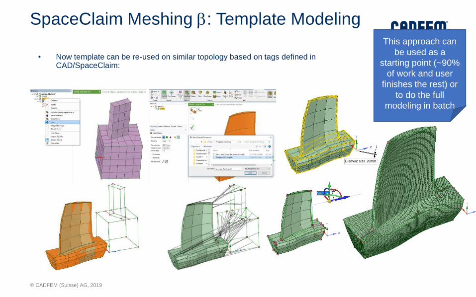
SpaceClaim Meshing b: Template Modeling
• Now template can be re-used on similar topology based on tags defined in CAD/SpaceClaim:
This approach can
be used as a
starting point (~90%
of work and user
finishes the rest) or
to do the full
modeling in batch

© CADFEM (Suisse) AG, 2019
Discovery Live

© CADFEM (Suisse) AG, 2019
Physics & Setup
• New boundary conditions
• Remote force• Define a force located off of the simulated parts
• Results in equivalent force and moment on contact faces
• Useful for replacing assembly forces with equivalents on smaller set of parts
• Functional supports• Cylindrical, spherical, hinged, planar
• Available types shown based on face shape
• Can be defined local to face or relative to global coordinate system
• Distributed mass• Adds mass evenly on designated faces
• Structural & modal
• Powerful ways to define location
• Named selections as condition location• Can be imported from CAD and updated via scripting
• Components / sub-assemblies as simulation region• All bodies within sub-assembly will be included in simulation
• Allows varying patterns of parts during simulation parameter study
© CADFEM (Suisse) AG, 2019
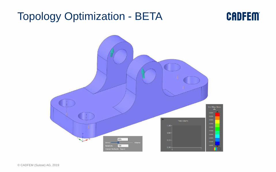
Topology Optimization - BETA

© CADFEM (Suisse) AG, 2019
Topology Optimization - BETA
• High speed, interactive, generates optimal shape from loading conditions & design constraints
• Level-set based approach
• Shape modified at each iteration
• Naturally smooth results
• Each shape is fully validated/solved
• High variation w/ changing constraints
• Specify ‘protected distance’ from boundary conditions
• Export result to faceted geometry
• Boundary condition locations transferred
• Optional additional smoothing
• BETA
• Preview of upcoming release
• Not feature complete
Starting part
70% original mass
30% original mass 50% original mass
© CADFEM (Suisse) AG, 2019
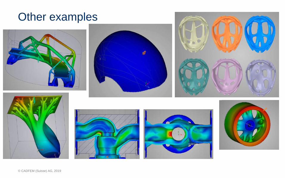
Other examples

© CADFEM (Suisse) AG, 2019
Smooth generative results
Boundary Locations preserved tightly and stored as group
Smoothing preserves small branches

© CADFEM (Suisse) AG, 2019
Results
• Multiple result displays now supported
• Ctrl+drag existing display to create additional
• Streamlines, vector plot, and particle emitters
• Independent sizing and visual properties
• Automatic placement at all inlets
• Interactive result handles
• Directly resize and reposition result displays from within the graphics scene
• Select and delete displays
• Saved result display settings
• All result display settings now saved with each solution
• Includes result variables, display positions, sizing, and visibility
• Solution fidelity % also saved
3D Tesla valve - Multiple streamlines in single solution
Multiple direction plots
Multiple particle emitters

© CADFEM (Suisse) AG, 2019
Calculators
• New type: value along path• Generate a chart or average value
calculated from a connected set of one or more curves
• Plot shows result value along length
• Curves must pass through simulation domain
• Curve position can be edited
• Modal frequency calculator• Select one mode or all modes• Display fixed frequency or chart
showing all frequencies
• Export all calculators• All chart data will be exported to
csv
• Body as location for calculator (BETA)• Select one body from multiple
body simulation to perform calculation on
Chart shows
values along path

© CADFEM (Suisse) AG, 2019
Miscellaneous
• Detail tab in ribbon - dimensions and notes
• Change BC type from minitoolbar
1,300 bodies30,000 faces
4.3 million triangles

© CADFEM (Suisse) AG, 2019
AIM updates
© CADFEM (Suisse) AG, 2019
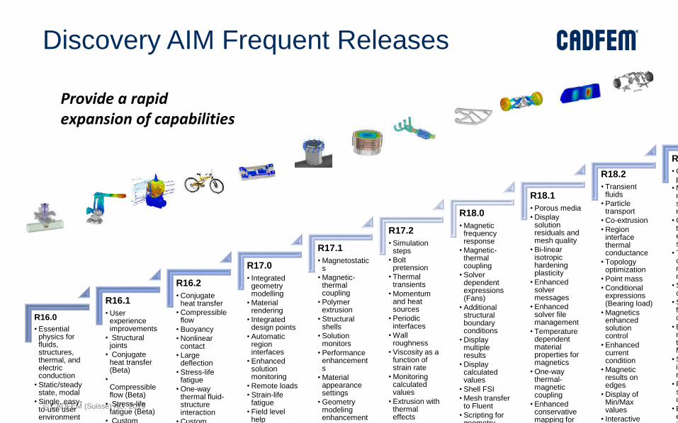
R16.0
• Essential physics for fluids, structures, thermal, and electric conduction
• Static/steady state, modal
• Single, easy-to-use user environment
• Geometry
R16.1
• User experience improvements
• Structural joints
• Conjugate heat transfer (Beta)
•Compressible flow (Beta)
• Stress-life fatigue (Beta)
• Custom templates
R16.2
• Conjugate heat transfer
• Compressible flow
• Buoyancy
• Nonlinear contact
• Large deflection
• Stress-life fatigue
• One-way thermal fluid-structure interaction
• Custom templates
R17.0
• Integrated geometry modelling
• Material rendering
• Integrated design points
• Automatic region interfaces
• Enhanced solution monitoring
• Remote loads
• Strain-life fatigue
• Field level help
• AIM on
R17.1
• Magnetostatics
• Magnetic-thermal coupling
• Polymer extrusion
• Structural shells
• Solution monitors
• Performance enhancements
• Material appearance settings
• Geometry modeling enhancements
R17.2
• Simulation steps
• Bolt pretension
• Thermal transients
• Momentum and heat sources
• Periodic interfaces
• Wall roughness
• Viscosity as a function of strain rate
• Monitoring calculated values
• Extrusion with thermal effects
• Geometry and
R18.0
• Magnetic frequency response
• Magnetic-thermal coupling
• Solver dependent expressions (Fans)
• Additional structural boundary conditions
• Display multiple results
• Display calculated values
• Shell FSI
• Mesh transfer to Fluent
• Scripting for geometry
R18.1
• Porous media
• Display solution residuals and mesh quality
• Bi-linear isotropic hardening plasticity
• Enhanced solver messages
• Enhanced solver file management
• Temperature dependent material properties for magnetics
• One-way thermal-magnetic coupling
• Enhanced conservative mapping for losses
R18.2
• Transient fluids
• Particle transport
• Co-extrusion
• Region interface thermal conductance
• Topology optimization
• Point mass
• Conditional expressions (Bearing load)
• Magnetics enhanced solution control
• Enhanced current condition
• Magnetic results on edges
• Display of Min/Max values
• Interactive results probe
R19.0
• Orthotropic porosity
• Multiple materials for solid thermal regions
• CHT and FSI template enhancements
• Topology optimization results monitoring
• Spring connections
• Small sliding for linear contact
• Enhanced model transfer to Mechanical
• Surface integral results
• Fill factor for stranded conductors
• Enhanced electromagnetics template
Discovery AIM Frequent Releases
Provide a rapid expansion of capabilities
© CADFEM (Suisse) AG, 2019
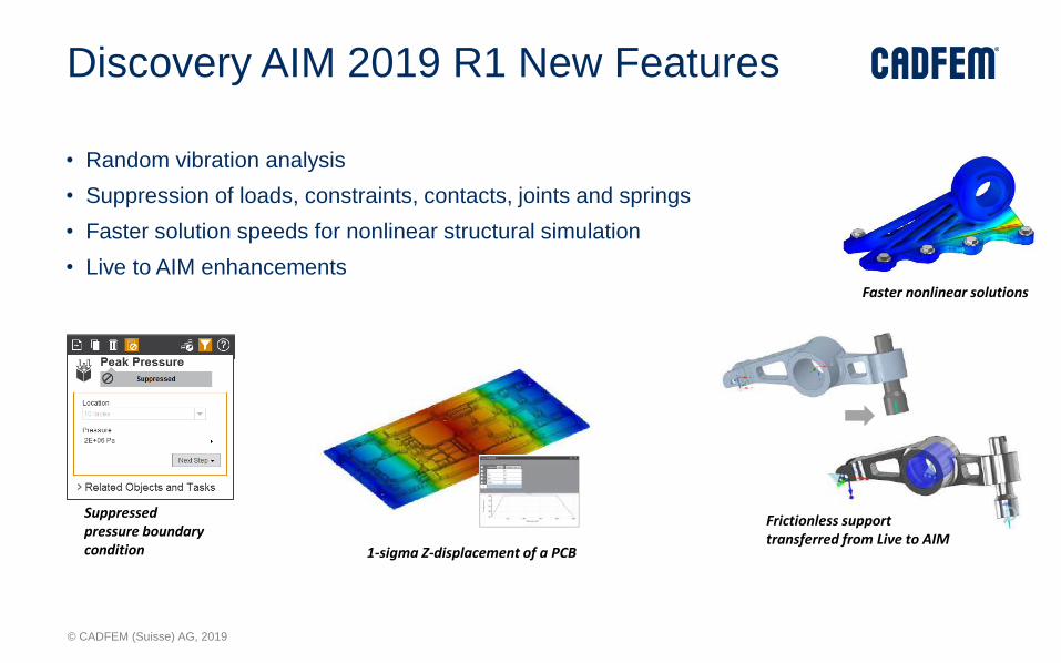
Discovery AIM 2019 R1 New Features
• Random vibration analysis
• Suppression of loads, constraints, contacts, joints and springs
• Faster solution speeds for nonlinear structural simulation
• Live to AIM enhancements
1-sigma Z-displacement of a PCB
Suppressed pressure boundary condition
Frictionless support transferred from Live to AIM
Faster nonlinear solutions
© CADFEM (Suisse) AG, 2019
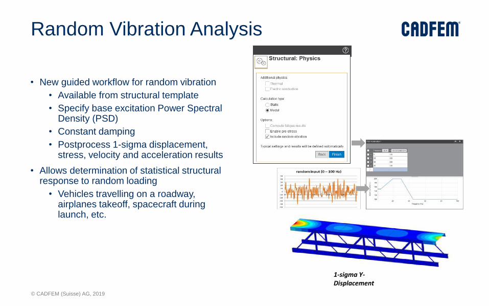
Random Vibration Analysis
• New guided workflow for random vibration
• Available from structural template
• Specify base excitation Power Spectral Density (PSD)
• Constant damping
• Postprocess 1-sigma displacement, stress, velocity and acceleration results
• Allows determination of statistical structural response to random loading
• Vehicles travelling on a roadway, airplanes takeoff, spacecraft during launch, etc.
1-sigma Y-Displacement
© CADFEM (Suisse) AG, 2019
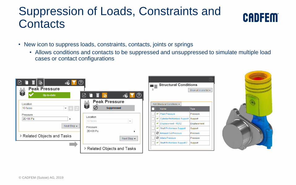
Suppression of Loads, Constraints and Contacts
• New icon to suppress loads, constraints, contacts, joints or springs
• Allows conditions and contacts to be suppressed and unsuppressed to simulate multiple load cases or contact configurations
© CADFEM (Suisse) AG, 2019
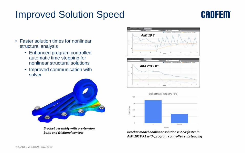
Improved Solution Speed
• Faster solution times for nonlinear structural analysis
• Enhanced program controlled automatic time stepping for nonlinear structural solutions
• Improved communication with solver
Bracket assembly with pre-tension bolts and frictional contact
AIM 2019 R1
Bracket model nonlinear solution is 2.5x faster in AIM 2019 R1 with program controlled substepping
AIM 19.2

© CADFEM (Suisse) AG, 2019
Live to AIM Enhancements
• Transfer of additional boundary conditions
• Swirl inlet condition
• Cylindrical, hinge, planar and spherical support
• Remote force
• Transient fluids
• Fluid simulation is transferred as transient if end time is specified
• Fluid simulation is transferred as steady-state if no end time is specified
© CADFEM (Suisse) AG, 2019
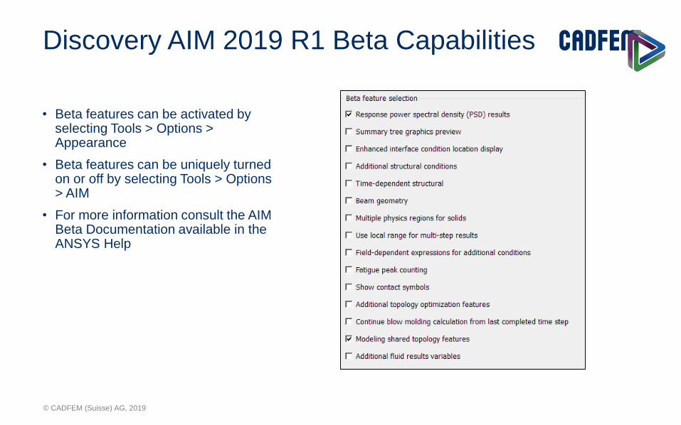
Discovery AIM 2019 R1 Beta Capabilities
• Beta features can be activated by selecting Tools > Options > Appearance
• Beta features can be uniquely turned on or off by selecting Tools > Options > AIM
• For more information consult the AIM Beta Documentation available in the ANSYS Help
© CADFEM (Suisse) AG, 2019
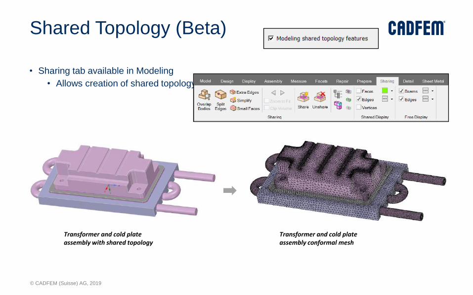
Shared Topology (Beta)
• Sharing tab available in Modeling
• Allows creation of shared topology for conformal meshing
Transformer and cold plate assembly with shared topology
Transformer and cold plate assembly conformal mesh

© CADFEM (Suisse) AG, 2019
Response PSD (Beta)
• Calculate response PSD at a vertex
• Displacement, velocity, acceleration, stress or strain response PSD
• Relative to the base or absolute
© CADFEM (Suisse) AG, 2019
Mechanical (Environnement)
© CADFEM (Suisse) AG, 2019
Mechanical Enhancements
© CADFEM (Suisse) AG, 2019
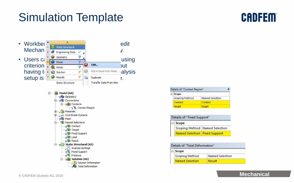
Simulation Template
• Workbench now allows users to enter/edit Mechanical without attaching geometry.
• Users can setup their analysis system using criterion based named selections without having to attach geometry. Such an analysis setup is called a Simulation Template.
Mechanical

© CADFEM (Suisse) AG, 2019
Attach/Replace Geometry
Once you attach a geometry, or for a system that already includes a geometry, the Replace Geometry option replaces Attach Geometry enabling you to replace an existing geometry.
• From Mechanical, the new option Attach Geometry, available from the Geometry object toolbar, enables you to import a geometry from with the application.
Mechanical
© CADFEM (Suisse) AG, 2019
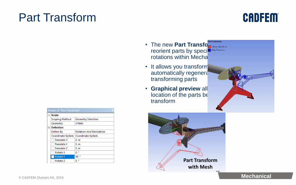
Part Transform
• The new Part Transform feature allows you to reorient parts by specifying translations and/or rotations within Mechanical
• It allows you transform mesh and/or automatically regenerate contacts along with transforming parts
• Graphical preview allows you to see the location of the parts before and after the transform
Part Transform with Mesh
Mechanical
© CADFEM (Suisse) AG, 2019
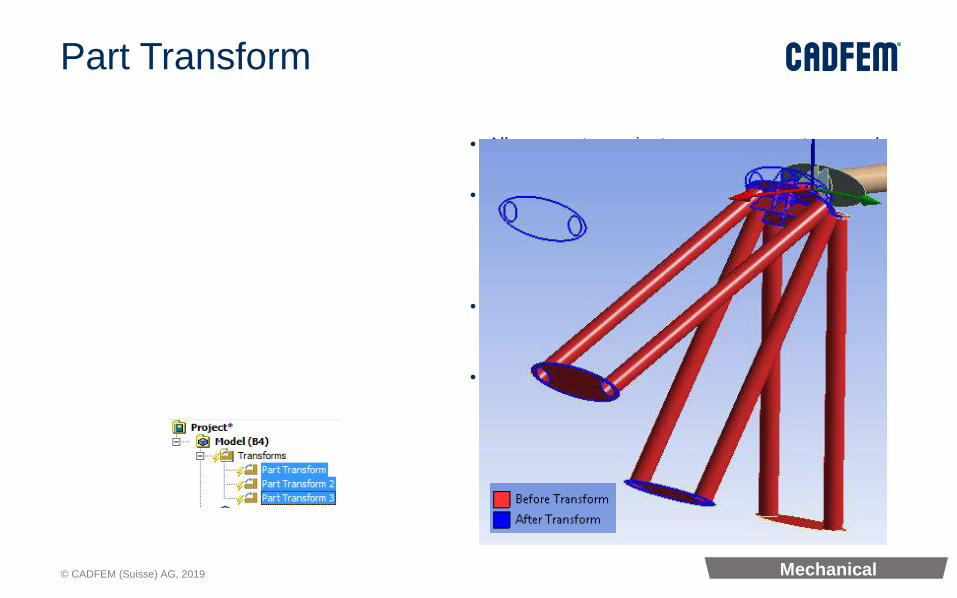
Part Transform
• Allows you to reorient one or more parts around arbitrary coordinate systems
• Allows you to reorient one or more parts using a pair of coordinate systems (source and target). The application automatically calculates the transform such that the source is aligned with the target after transform.
• You can apply multiple transforms to a part. The transforms are applied in the order they appear in the tree.
• You can reorder the transforms by drag-drop in the tree.
Mechanical
© CADFEM (Suisse) AG, 2019
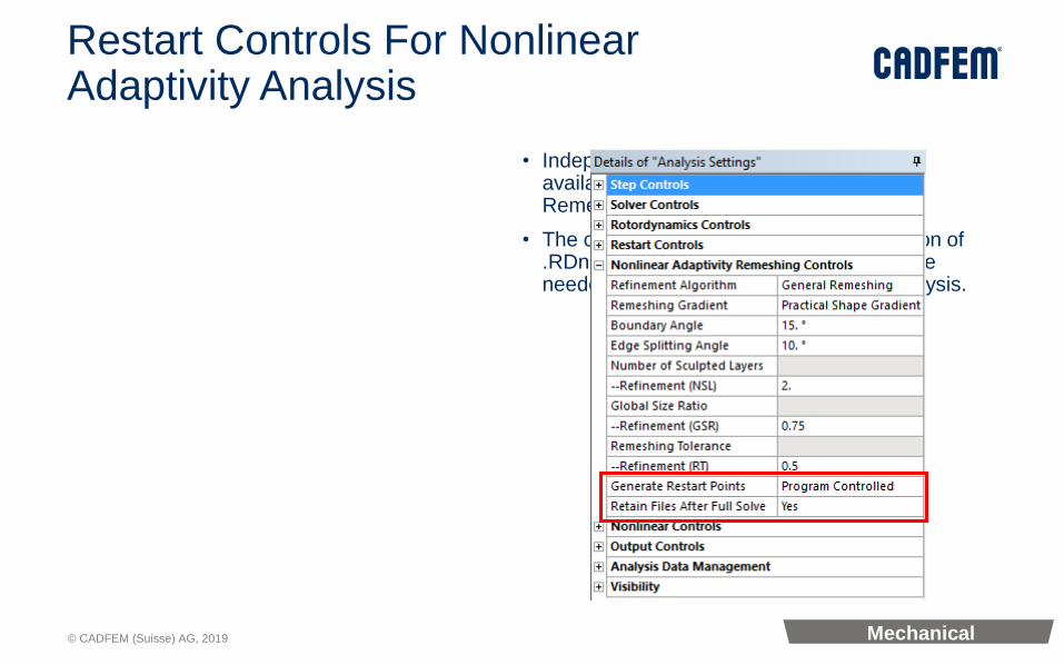
Restart Controls For Nonlinear Adaptivity Analysis
• Independent Restart Controls are now available under Nonlinear Adaptivity Remeshing Controls.
• The options control the generation/retention of .RDnn remeshing database files, which are needed for mesh nonlinear adaptivity analysis.
Mechanical
© CADFEM (Suisse) AG, 2019
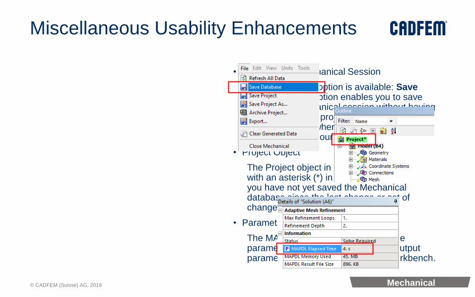
Miscellaneous Usability Enhancements
• Quickly Save Mechanical Session
A new File menu option is available: Save Database. This option enables you to save the current Mechanical session without having to save the entire project. However, you must save the project when you exit the application to properly save your changes.
• Project Object
The Project object in the Outline now displays with an asterisk (*) in its name to indicate that you have not yet saved the Mechanical database since the last change or set of changes.
• Parametrizing MAPDL Elapsed Time
The MAPDL Elapsed Time can now be parametrized and is available as an output parameter in the Parameter Set in workbench.
Mechanical

© CADFEM (Suisse) AG, 2019
New Solution Combination• With the new solution combination, users can:
• Specify multiple combinations.• Combine solutions for Static Structural, Transient Structural, and
Harmonic Response analyses.• Specify solution combinations as either Linear or SRSS (Square Root
of Summation of Squares).• Use Tabular Data or a result Set Number to specify which combination
you wish to display.• Import and/or Export the Solution Combination Worksheet as a Comma
Separated Value (CSV) file.
Mechanical

© CADFEM (Suisse) AG, 2019
Keyframe Animation for Results
• Keyframe animation enables you to string together different
snapshots of the model in the Geometry window to create an
animation
• Keyframes are created by positioning the model in the desired
orientation and clicking on Create Keyframe.
• The application interpolates the transition from keyframe to
keyframe to create a smooth animation.
• Export the video in various formats:
MP4, WMV , AVI and GIF
Mechanical

© CADFEM (Suisse) AG, 2019
• Keyframe animation for Results enables stitching
different snapshots (different view settings) of the model
for smooth visualization of results, coordinating the
animation in time/steps space (natural for results) with
the one in the 3D space (natural for keyframe
animation).
• This can be enabled by clicking the keyframe animation
icon in the animation toolbar and the user can have a
choice of synchronizing the frame rate similar to the one
set in the keyframe animation window
Frames Synchronized with Keyframe animation
Keyframe Animation for Results
Mechanical
© CADFEM (Suisse) AG, 2019
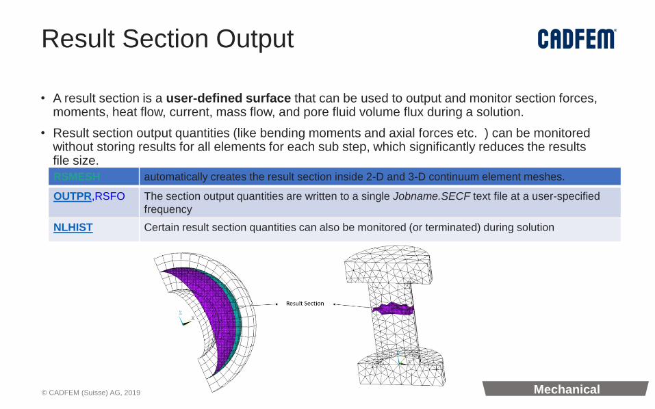
Result Section Output
• A result section is a user-defined surface that can be used to output and monitor section forces, moments, heat flow, current, mass flow, and pore fluid volume flux during a solution.
• Result section output quantities (like bending moments and axial forces etc. ) can be monitored without storing results for all elements for each sub step, which significantly reduces the results file size.
RSMESH automatically creates the result section inside 2-D and 3-D continuum element meshes.
OUTPR,RSFO The section output quantities are written to a single Jobname.SECF text file at a user-specified
frequency
NLHIST Certain result section quantities can also be monitored (or terminated) during solution
Mechanical

© CADFEM (Suisse) AG, 2019
3-D Half Model of a Simplified Bolt Joint
Result Section in the Bolt at y = 280
/PREP7
ESEL,S,TYPE,,105 ! Select the bolt elements
RSMESH, , ,,y,280,,,elgr
/SOLU
OUTPR,RSFO,5 ! Define the frequency to output results
Result Section in a Bolt Thread Model
• This 3-D model represents an M120 structural steel bolt with standard thread dimensions.• The model includes a cover plate and a base plate. A bilinear isotropic plastic material model is
used for the bolt and the plates.
Mechanical

© CADFEM (Suisse) AG, 2019
Switching Analysis Type between 2D and 3D (19.1)
• Mechanical no longer restricts users from changing the Analysis Type (2D/3D) after the first attach.
• Previously, the Analysis Type had to be specified when users first attached their model and could not be changed.
Mechanical

© CADFEM (Suisse) AG, 2019
New Materials Folder (19.1)
• The Mechanical tree now contains a new Materials folder which contains material related information for your analysis
• Each Material used in the analysis is shown as an object in the tree, showing common material properties and indicating which bodies are using it
• Additionally this folder contains other material related objects including Material Assignments, Material Plots, and Imported Material Fields
Mechanical
© CADFEM (Suisse) AG, 2019
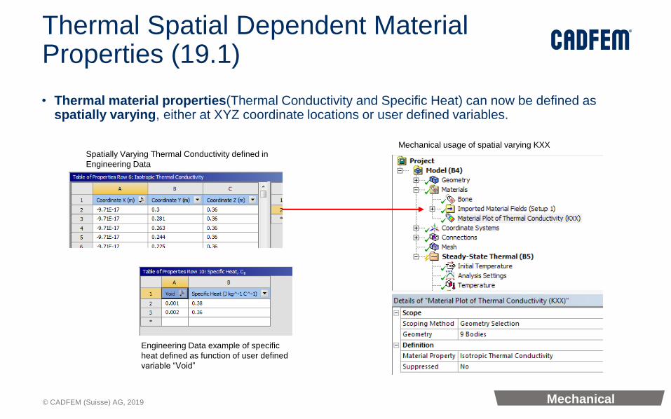
Thermal Spatial Dependent Material Properties (19.1)
• Thermal material properties(Thermal Conductivity and Specific Heat) can now be defined as spatially varying, either at XYZ coordinate locations or user defined variables.
Spatially Varying Thermal Conductivity defined in
Engineering Data
Mechanical usage of spatial varying KXX
Engineering Data example of specific
heat defined as function of user defined
variable “Void”
Mechanical

© CADFEM (Suisse) AG, 2019
Result Plot Trackers During Solution (19.1)
• The Solution Information object provides Result Plot Tracker options that enable you to view result contours in real time as the solution progresses. Furthermore, you can add Result Plot Trackers at any point during the solution process.
• In the previous release, this feature was only available for Topology Optimization analyses. Now, this feature has been expanded to include Structural and Thermal analysis.
Mechanical

© CADFEM (Suisse) AG, 2019
MP4, WMV Animation Export (19.1)
• Animations can now be exported in multiple file formats.
• AVI, MP4 and WMV video file types can be created offering more flexibility.
Mechanical

© CADFEM (Suisse) AG, 2019
New interface 2019R2
© CADFEM (Suisse) AG, 2019
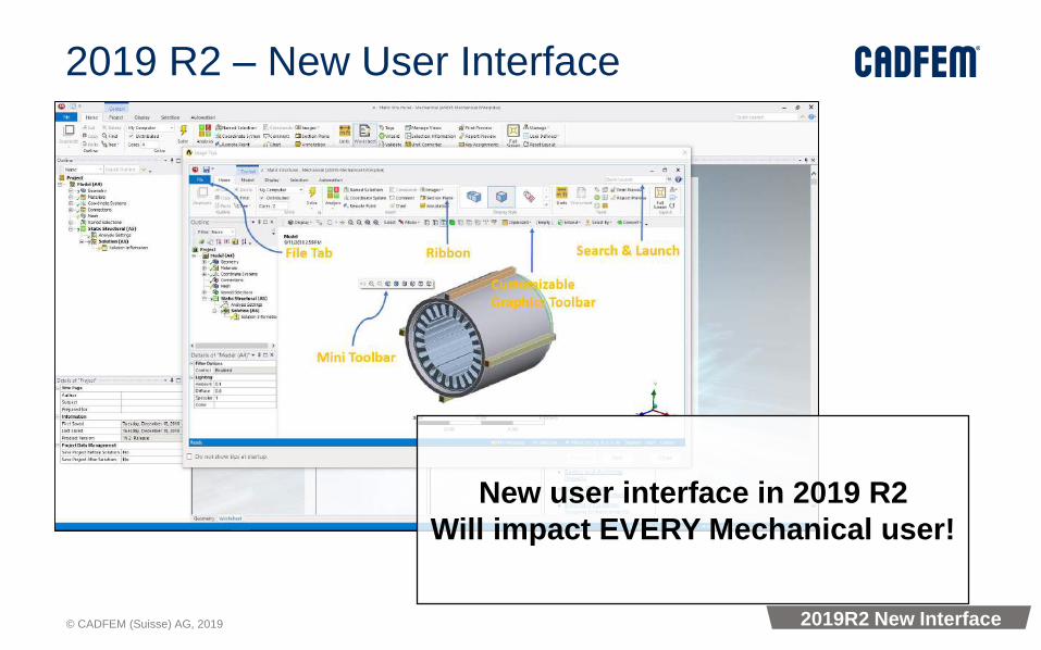
2019 R2 – New User Interface
New user interface in 2019 R2
Will impact EVERY Mechanical user!
2019R2 New Interface

© CADFEM (Suisse) AG, 2019
Mechanical (Analyses)
© CADFEM (Suisse) AG, 2019
Semi-implicit Method

© CADFEM (Suisse) AG, 2019
Semi-Implicit Method
• Goal: • To solve complex problems that encounter convergence difficulty in an implicit
solver by switching to explicit time integration• Support most features (e.g. CEs, LMs, Higher order elements, Joints, UP) of
MAPDL
• Basic Idea: • Central difference time integration (explicit/semi-implicit) transforms governing
equations in an explicit form that does not need Newton-Raphson iterations
• Semi-Implicit Method guarantees a solution• Start with Implicit• Convergence difficulty ?-> Change to explicit to overcome hump • Past the most non-linear part?-> Change back to implicit solver
Semi-Implicit
© CADFEM (Suisse) AG, 2019
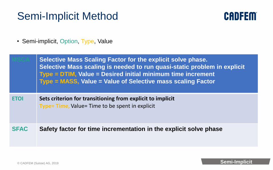
Semi-Implicit Method
• Semi-implicit, Option, Type, Value
MSCA Selective Mass Scaling Factor for the explicit solve phase.
Selective Mass scaling is needed to run quasi-static problem in explicit
Type = DTIM, Value = Desired initial minimum time increment
Type = MASS, Value = Value of Selective mass scaling Factor
ETOI Sets criterion for transitioning from explicit to implicitType= Time, Value= Time to be spent in explicit
SFAC Safety factor for time incrementation in the explicit solve phase
Semi-Implicit
© CADFEM (Suisse) AG, 2019
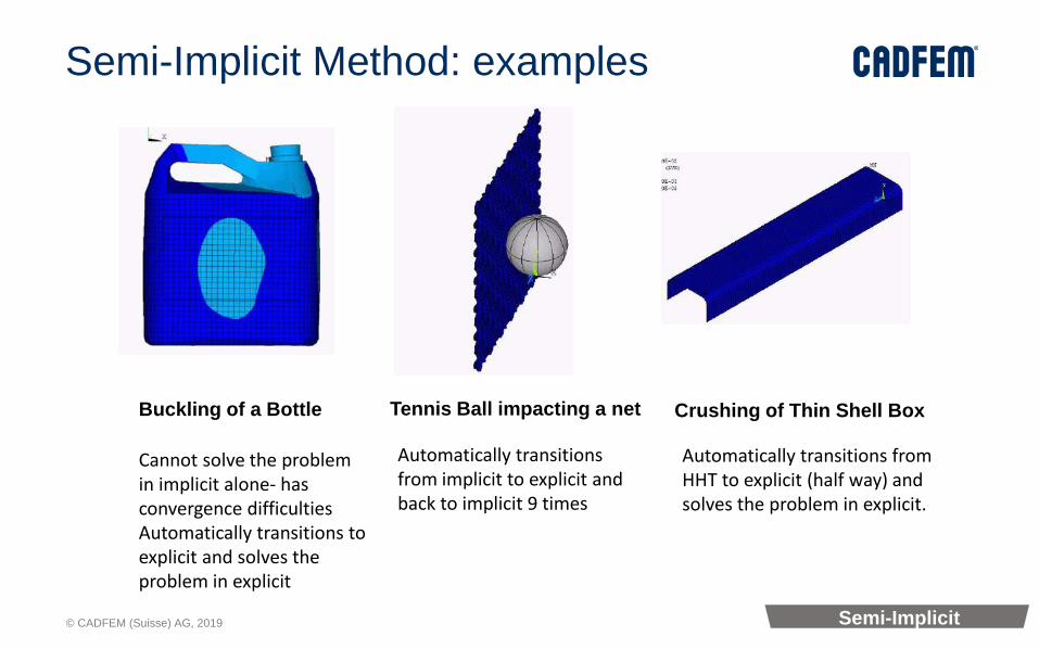
Buckling of a Bottle
Cannot solve the problem in implicit alone- has convergence difficultiesAutomatically transitions to explicit and solves the problem in explicit
Semi-Implicit Method: examples
Automatically transitions from implicit to explicit and back to implicit 9 times
Crushing of Thin Shell Box
Automatically transitions from HHT to explicit (half way) and solves the problem in explicit.
Tennis Ball impacting a net
Semi-Implicit

© CADFEM (Suisse) AG, 2019
Semi-Implicit Method vs. Implicit
Implicit
Implicit Explicit Implicit
No convergence reached.
Pure
Im
plic
itS
em
i-Im
plic
it

© CADFEM (Suisse) AG, 2019
SMART Crack Growth (Separating, Morphing, Adaptive, and Remeshing Technology)
© CADFEM (Suisse) AG, 2019
SMART Crack Growth Simulation
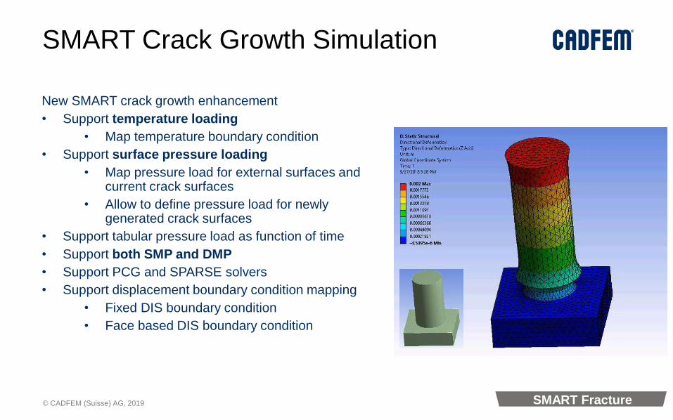
New SMART crack growth enhancement
• Support temperature loading
• Map temperature boundary condition
• Support surface pressure loading
• Map pressure load for external surfaces and current crack surfaces
• Allow to define pressure load for newly generated crack surfaces
• Support tabular pressure load as function of time
• Support both SMP and DMP
• Support PCG and SPARSE solvers
• Support displacement boundary condition mapping
• Fixed DIS boundary condition
• Face based DIS boundary condition
SMART Fracture
© CADFEM (Suisse) AG, 2019
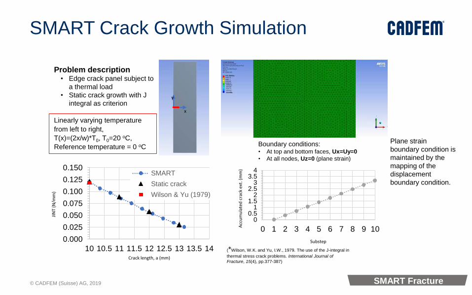
Problem description• Edge crack panel subject to
a thermal load
• Static crack growth with J
integral as criterionx
y
Linearly varying temperature
from left to right,
T(x)=(2x/w)*T0, T0=20 oC,
Reference temperature = 0 oC Boundary conditions:• At top and bottom faces, Ux=Uy=0
• At all nodes, Uz=0 (plane strain)
0.000
0.025
0.050
0.075
0.100
0.125
0.150
10 10.5 11 11.5 12 12.5 13 13.5 14
SMART
Static crack
Wilson & Yu (1979)
Crack length, a (mm)
JIN
T (N
/mm
)
(*Wilson, W.K. and Yu, I.W., 1979. The use of the J-integral in
thermal stress crack problems. International Journal of
Fracture, 15(4), pp.377-387)
SubstepA
ccu
mu
late
d c
rack
ext
. (m
m)
00.5
11.5
22.5
33.5
4
0 1 2 3 4 5 6 7 8 9 10
Plane strain
boundary condition is
maintained by the
mapping of the
displacement
boundary condition.
SMART Crack Growth Simulation
SMART Fracture

© CADFEM (Suisse) AG, 2019
SMART Crack Growth Simulation
• Center crack panel subjected to surface pressure
𝐽 = 1 − 𝜈2𝐾𝐼2
𝐸(plane strain)
𝐽 =𝐾𝐼2
𝐸(plane stress)
𝐾𝐼 = 𝑝 𝜋𝑎 𝐹𝑎
𝑊
𝐹𝑎
𝑊=1 − 0.5
𝑎𝑊 + 0.370
𝑎𝑊
2
− 0.044𝑎𝑊
3
1 − 𝑎/𝑊
(The Stress Analysis of Cracks Handbook, ASME, 2000, Page 41)
J-in
tegr
al (
N/m
m)
time
00.20.40.60.8
11.21.41.61.8
2
0 0.1 0.2 0.3 0.4 0.5 0.6 0.7 0.8 0.9 1
J (plane stress)
J (plane strain)
Left crack front
Right crack front
JIC = 0.1 N/mm
J (average of 5 contours) evaluated at the middle of the crack front
Problem description• Tensile panel with a center crack
• Static crack growth with J integral
as criterion
SMART Fracture

© CADFEM (Suisse) AG, 2019
# of CPU Time (s) Speedup in
total
1 8799 1
8 2010 4.38
16 1327 6.63
32 991 8.88
Elements: 0.67M
Equations: 2.7M
Crack tips : 101
Remeshing: 3 times
Distributed Solution
• Work within ANSYS distributed solution architecture
• FEM model solved in distributed mode
• Fracture and SMART Crack Growth Calculation including remeshing are conducted only in master node
Pressure loads
Solution 2
# of CPU Time (seconds) Speedup
1 163 1
2 109 1.50
4 82 1.98
8 70 2.32
16 72 2.26
Elements: 0.058M
Equations: 0.23M
Crack tips : 23
Remeshing: 5 times
Solution 1
SMART Crack Growth Simulation
SMART Fracture
© CADFEM (Suisse) AG, 2019
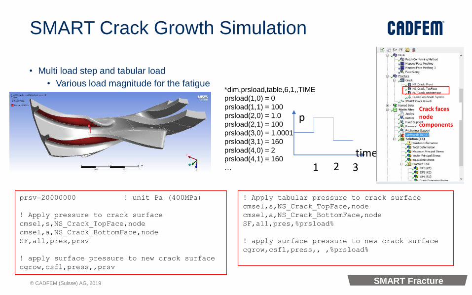
SMART Crack Growth Simulation
• Multi load step and tabular load
• Various load magnitude for the fatigue
•
SMART Fracture
*dim,prsload,table,6,1,,TIME
prsload(1,0) = 0
prsload(1,1) = 100
prsload(2,0) = 1.0
prsload(2,1) = 100
prsload(3,0) = 1.0001
prsload(3,1) = 160
prsload(4,0) = 2
prsload(4,1) = 160
…
p
time1 2 3
prsv=20000000 ! unit Pa (400MPa)
! Apply pressure to crack surface
cmsel,s,NS_Crack_TopFace,node
cmsel,a,NS_Crack_BottomFace,node
SF,all,pres,prsv
! apply surface pressure to new crack surface
cgrow,csfl,press,,prsv
! Apply tabular pressure to crack surface
cmsel,s,NS_Crack_TopFace,node
cmsel,a,NS_Crack_BottomFace,node
SF,all,pres,%prsload%
! apply surface pressure to new crack surface
cgrow,csfl,press,, ,%prsload%
Crack faces node components

© CADFEM (Suisse) AG, 2019
SMART Crack Growth Simulation
• Example:
SMART Fracture

© CADFEM (Suisse) AG, 2019
XFEM crack modeling
• Avoiding remeshing:
XFEM Fracture
© CADFEM (Suisse) AG, 2019
General Axisymmetric

© CADFEM (Suisse) AG, 2019
General Axisymmetric in WB-Mechanical
• Applicable for 3D Static Structural analysis. General Axisymmetric definition is added under Symmetry folder and when scoped to 2D/Surface body makes the behavior of that Body as General Axisymmetric
General Axisymmetry
© CADFEM (Suisse) AG, 2019
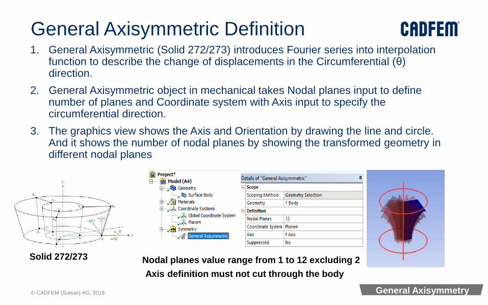
General Axisymmetric Definition1. General Axisymmetric (Solid 272/273) introduces Fourier series into interpolation
function to describe the change of displacements in the Circumferential (θ) direction.
2. General Axisymmetric object in mechanical takes Nodal planes input to define number of planes and Coordinate system with Axis input to specify the circumferential direction.
3. The graphics view shows the Axis and Orientation by drawing the line and circle. And it shows the number of nodal planes by showing the transformed geometry in different nodal planes
Solid 272/273 Nodal planes value range from 1 to 12 excluding 2
Axis definition must not cut through the body
General Axisymmetry

© CADFEM (Suisse) AG, 2019
Stress shown in all nodal planes when scoped to an edge
Total deformation scoped to All Bodies
General Axisymmetric: Results
1. All regular results can be extracted on the General Axisymmetric body scoping or Mesh. The results shown below are Deformation and Stress which are symmetric in the circumferential direction in the presence of Axisymmetric loading applied in this case
General Axisymmetry

© CADFEM (Suisse) AG, 2019
General Axisymmetric: Example
General Axisymmetry
© CADFEM (Suisse) AG, 2019
Topology Optimization

© CADFEM (Suisse) AG, 2019
Stress constraint
• Support stress constraints in the region outside of Optimization region. It could be exclusion region or other parts of the entire model.
Local Von-Mises Stress
constraint of 7 MPa is applied
to connector edges which is
not part of Optimization
region
Topology density
results in the
Optimization region
Topology optimization
© CADFEM (Suisse) AG, 2019
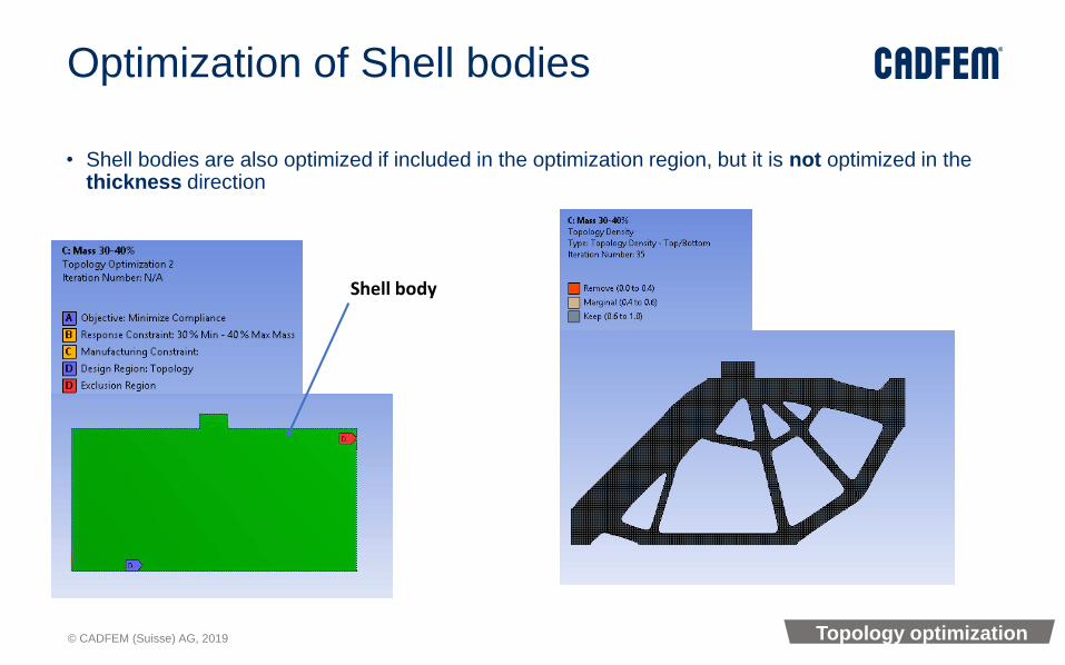
Optimization of Shell bodies
• Shell bodies are also optimized if included in the optimization region, but it is not optimized in the thickness direction
Shell body
Topology optimization
© CADFEM (Suisse) AG, 2019
Smoothing Result
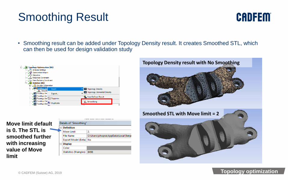
• Smoothing result can be added under Topology Density result. It creates Smoothed STL, which can then be used for design validation study
Topology Density result with No Smoothing
Smoothed STL with Move limit = 2
Move limit default
is 0. The STL is
smoothed further
with increasing
value of Move
limit
Topology optimization
© CADFEM (Suisse) AG, 2019
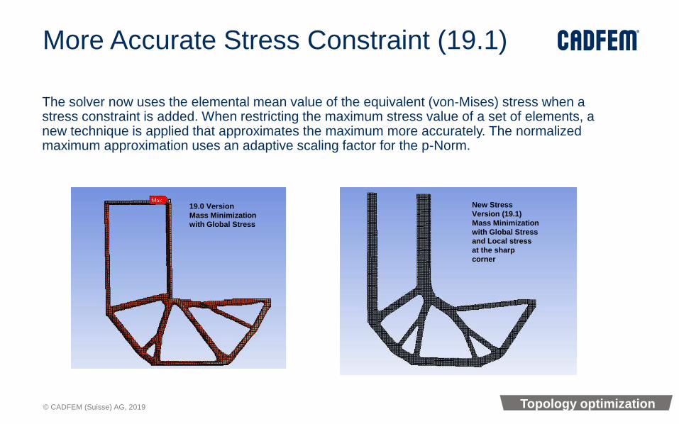
More Accurate Stress Constraint (19.1)
The solver now uses the elemental mean value of the equivalent (von-Mises) stress when a stress constraint is added. When restricting the maximum stress value of a set of elements, a new technique is applied that approximates the maximum more accurately. The normalized maximum approximation uses an adaptive scaling factor for the p-Norm.
19.0 Version
Mass Minimization
with Global Stress
New Stress
Version (19.1)
Mass Minimization
with Global Stress
and Local stress
at the sharp
corner
Topology optimization

© CADFEM (Suisse) AG, 2019
Topology Optimization (19.2)
• Lattice Optimization option to calculate lattice density
Source: ANSYS
Minimum Density Maximum Density
Topology optimization
© CADFEM (Suisse) AG, 2019
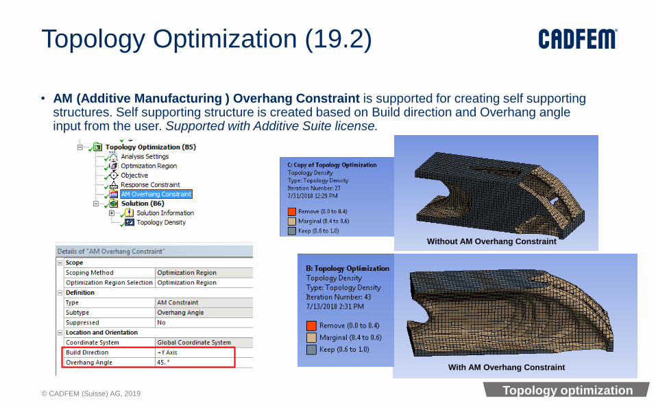
Topology Optimization (19.2)
• AM (Additive Manufacturing ) Overhang Constraint is supported for creating self supporting structures. Self supporting structure is created based on Build direction and Overhang angle input from the user. Supported with Additive Suite license.
Without AM Overhang Constraint
With AM Overhang Constraint
Topology optimization

© CADFEM (Suisse) AG, 2019
Additive Manufacturing(AM)
© CADFEM (Suisse) AG, 2019
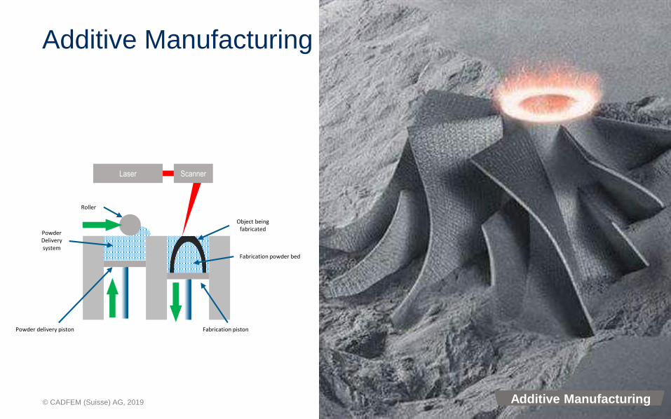
Additive Manufacturing
ScannerLaser
Powder delivery piston
Fabrication powder bed
Fabrication piston
PowderDeliverysystem
Object beingfabricated
Roller
Additive Manufacturing

© CADFEM (Suisse) AG, 2019
The AM Promise
1. Impossible to Manufacture
2. Lightweighting
3. Part Consolidation
4. Multifunctional Designs
5. Distributed Production
6. New Material Properties
7. Replacement Parts
8. Customization
9. …
Additive Manufacturing
© CADFEM (Suisse) AG, 2019
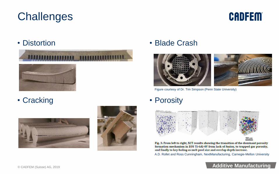
Challenges
• Distortion
• Cracking
• Blade Crash
• Porosity
Figure courtesy of Dr. Tim Simpson (Penn State University)
A.D. Rollet and Ross Cunningham, NextManufacturing, Carnegie-Mellon University
Additive Manufacturing
© CADFEM (Suisse) AG, 2019
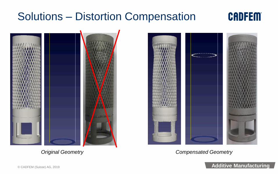
Solutions – Distortion Compensation
Compensated GeometryOriginal Geometry
Additive Manufacturing

© CADFEM (Suisse) AG, 2019
Solutions – Support Optimization
Based on stresses, define support sizing
Courtesy Tim Gornet, University of Louisville
Supports Generated by Magics Optimized Supports
Additive Manufacturing
© CADFEM (Suisse) AG, 2019
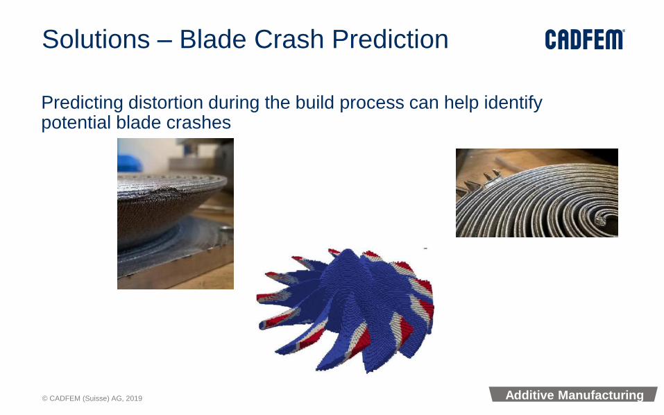
Solutions – Blade Crash Prediction
Predicting distortion during the build process can help identify potential blade crashes
Additive Manufacturing

© CADFEM (Suisse) AG, 2019
Workbench ViewEnd-to-End WorkflowParametric
Design Process Simulation
Additive Manufacturing
© CADFEM (Suisse) AG, 2019
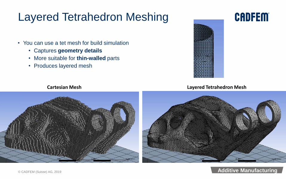
Layered Tetrahedron Meshing
• You can use a tet mesh for build simulation
• Captures geometry details
• More suitable for thin-walled parts
• Produces layered mesh
Cartesian Mesh Layered Tetrahedron Mesh
Additive Manufacturing
© CADFEM (Suisse) AG, 2019
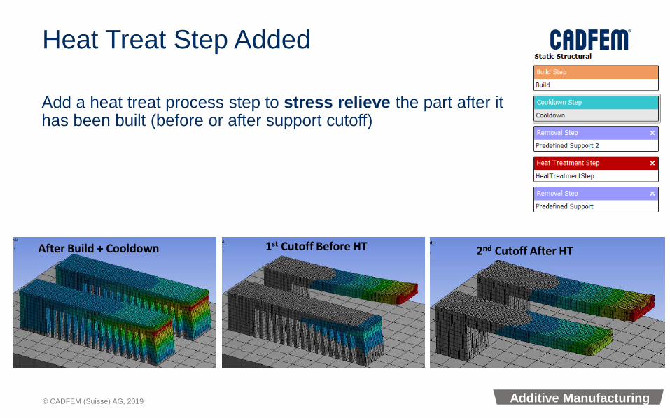
Heat Treat Step Added
Add a heat treat process step to stress relieve the part after it has been built (before or after support cutoff)
After Build + Cooldown 1st Cutoff Before HT 2nd Cutoff After HT
Additive Manufacturing

© CADFEM (Suisse) AG, 2019
Allow Powder In Build Step
You can now include material that remains as powder during the build.
Useful to consider heat transfer between close parts or close part features
No Powder (Equivalent Convection) With Powder
Additive Manufacturing

© CADFEM (Suisse) AG, 2019
Porosity Parametric
• New Additive Science Feature
• Global porosity of part dependent on laser power, laser speed and scanning strategy
• Parametric Capability: up to 300 permutations
• Tuned and validated for multiple materials
Additive Manufacturing

© CADFEM (Suisse) AG, 2019
Solver & HPC
© CADFEM (Suisse) AG, 2019
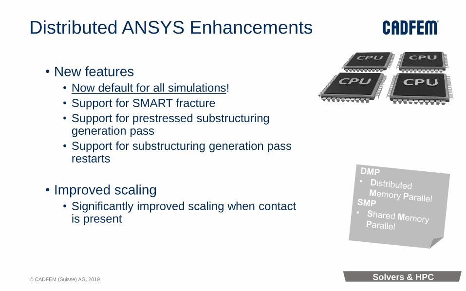
Distributed ANSYS Enhancements
• New features• Now default for all simulations!
• Support for SMART fracture
• Support for prestressed substructuringgeneration pass
• Support for substructuring generation pass restarts
• Improved scaling• Significantly improved scaling when contact
is present
Solvers & HPC

© CADFEM (Suisse) AG, 2019
Distributed ANSYS Enhancements
• Scaling when contact is present
• Symmetric contact pairs improved• In previous releases both sets of contact and target surfaces for a symmetric
contact pair would reside in a single domain → Now each pair can be decomposed into different domains.
• MPC contact pairs improved• In previous releases if an MPC and a non-MPC contact pair touched or
overlapped, they would both reside in a single domain → These contact pairs can now be decomposed to different domains.
• Contact pair splitting• CNCH,DMP → Automatically split contact pairs during solution
• CNCH,SPLIT → Manually split contact pairs
• CNCH,MERGE → Manually merge contact pair
Solvers & HPC

© CADFEM (Suisse) AG, 2019
Engine Block with Gasket
Original target surface
Original contact surfaceSplit contact surfacesfrom the real ID=18
Trimmed target surfacesfrom the real ID=18
Full model
Original contact pairs
Decomposed into9 sub-pairs
Distributed Contact
© CADFEM (Suisse) AG, 2019
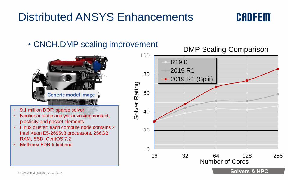
Distributed ANSYS Enhancements
• CNCH,DMP scaling improvement
• 9.1 million DOF; sparse solver
• Nonlinear static analysis involving contact,
plasticity and gasket elements
• Linux cluster; each compute node contains 2
Intel Xeon E5-2695v3 processors, 256GB
RAM, SSD, CentOS 7.2
• Mellanox FDR Infiniband
Generic model image
Solvers & HPC
0
20
40
60
80
100
16 32 64 128 256
Solv
er
Rating
Number of Cores
DMP Scaling Comparison
R19.0
2019 R1
2019 R1 (Split)
© CADFEM (Suisse) AG, 2019
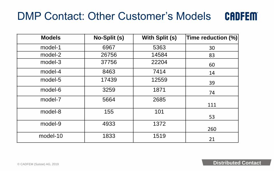
DMP Contact: Other Customer’s Models
Distributed Contact
Models No-Split (s) With Split (s) Time reduction (%)
model-1 6967 5363 30model-2 26756 14584 83model-3 37756 22204 60model-4 8463 7414 14model-5 17439 12559
39model-6 3259 1871 74model-7 5664 2685
111model-8 155 101
53model-9 4933 1372
260model-10 1833 1519
21

© CADFEM (Suisse) AG, 2019
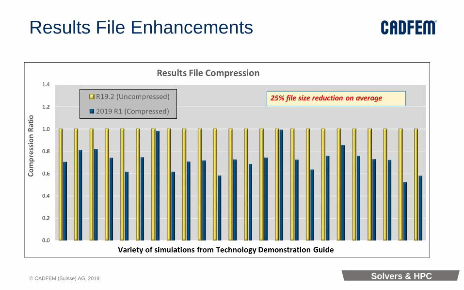
Results File Enhancements
• OUTRES command changes• Eight new result item labels have been added
• New compression algorithm available (sparsify)• Activated via the /FCOMP,RST,SPARSE command
• Lossless compression of results file data
• Typically reduces results file size by 10-50%
• Virtually no performance penalty
Solvers & HPC
© CADFEM (Suisse) AG, 2019
Results File Enhancements
Solvers & HPC

© CADFEM (Suisse) AG, 2019
Workbench Material Designer

© CADFEM (Suisse) AG, 2019
Material Designer
© CADFEM (Suisse) AG, 2019
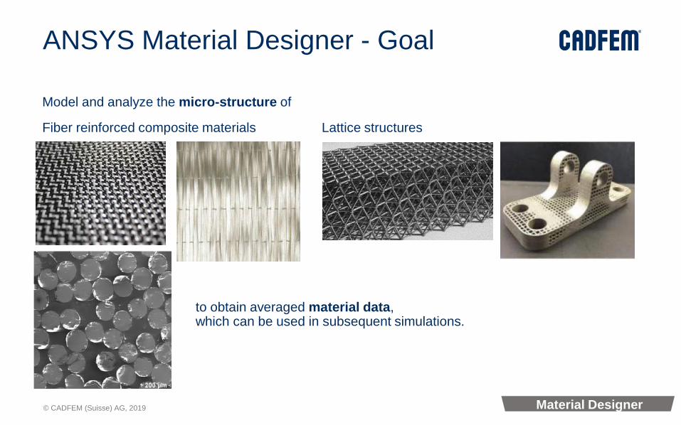
ANSYS Material Designer - Goal
Model and analyze the micro-structure of
Fiber reinforced composite materials Lattice structures
to obtain averaged material data,which can be used in subsequent simulations.
Material Designer
© CADFEM (Suisse) AG, 2019
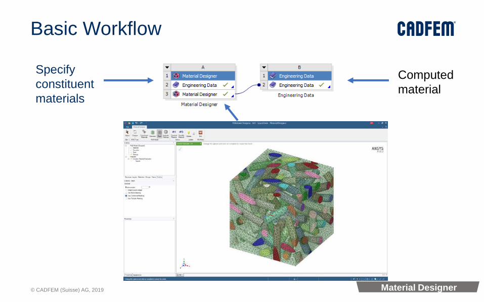
Basic Workflow
Specify
constituent
materials
Computed
material
Material Designer

© CADFEM (Suisse) AG, 2019
Homogenization
Material Designer employs the following procedure:
• Model the micro-structure (RVE/unit cell)
• Expose it to a set of load cases
• Extract the (force) results
• Obtain homogenized (averaged) material properties
Material Designer

© CADFEM (Suisse) AG, 2019
Parameter Dependence
Materials depend on some parameters:
For instance
● fiber volume fraction
● shear angle
● relative density (volume fraction)
● ...
Generate a variable material that depends on these parameters
Use variable material data in subsequent analyses
Material Designer

© CADFEM (Suisse) AG, 2019
Why use Material Designer: Powerful RVE Creation
It has never been so easy to get started with multi-scale analysis to create the following RVEs just with a few clicks and compute homogenized material properties
Material Designer

© CADFEM (Suisse) AG, 2019
Why use Material Designer 2: RVEs are parametric
RVE models are parameterized, variations can be run out of the box
Material Designer

© CADFEM (Suisse) AG, 2019
Material Designer: Example
Material Steel
Gewicht 7.18 kg Gewicht 35 kg
MyMat
Material Designer

© CADFEM (Suisse) AG, 2019
Computed Material Properties
The following properties can be computed:
• Structural
• Linear Elasticity
• Orthotropic elasticity (Young’s moduli, Poisson ratios, shear moduli)
• Anisotropic elasticity (stiffness matrix)
• Density
• Thermal
• Orthotropic secant coefficients of thermal expansion
• Orthotropic thermal conductivity
• Specific heat
• Remark: for nonlinear
• Put the geometry into Mechanical/SC
Material Designer

© CADFEM (Suisse) AG, 2019
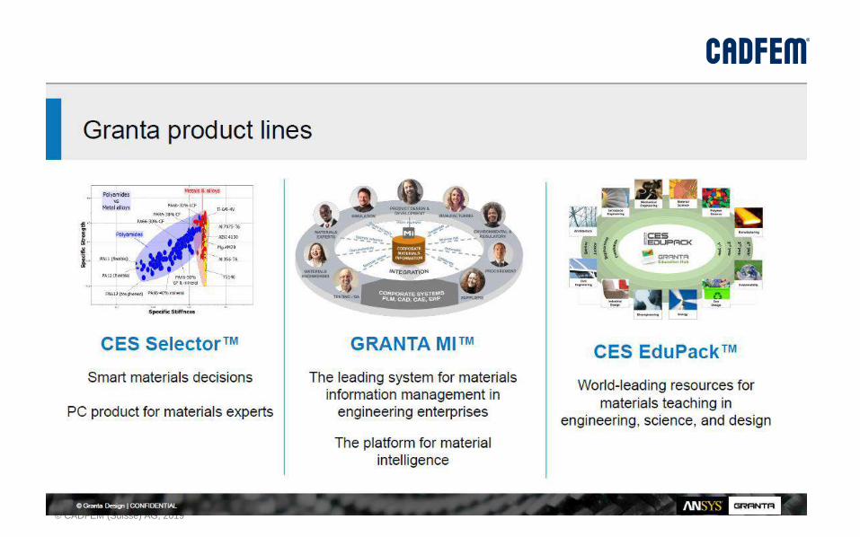
Granta Design

© CADFEM (Suisse) AG, 2019
Granta Design
Granta Design

© CADFEM (Suisse) AG, 2019
Granta Design
Granta Design

© CADFEM (Suisse) AG, 2019
Granta Materialdatabase
50% of this expensively-
acquired data was
USED ONCE and
NEVER RE-USED.
Typically,
20% of materials tests
DUPLICATE
existing work.
The average engineer spent
30 MINS PER WEEKjust looking for
materials data.
Granta Design 2016 survey 300+
respondents
MaterialUniverse
▪ All engineering materials
▪ Complete & comparable
▪ Price & eco data
▪ Compiled by materials experts
▪ Datasheet for generic grade
▪ Linked to specialist datasets
✓ Unique
✓ Comprehensive
✓ Linked
Granta Design
MMPDS
MIL-HDBK-17
Firehole
Composites
Steelspec
StahlDat SX
MI-21
Prospector ®
Plastics
CAMPUS®
& M-Base
MaterialUniverse™
ecoInvent
materials ESDUASME BPVC
Powder
Metallurgy
Sheet Steels
Senvol Database™
JAHM Curve Data
© CADFEM (Suisse) AG, 2019
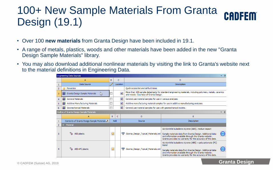
100+ New Sample Materials From GrantaDesign (19.1)
• Over 100 new materials from Granta Design have been included in 19.1.
• A range of metals, plastics, woods and other materials have been added in the new "GrantaDesign Sample Materials" library.
• You may also download additional nonlinear materials by visiting the link to Granta's website next to the material definitions in Engineering Data.
Granta Design
© CADFEM (Suisse) AG, 2019
CMS in WB-Mechanical
126

© CADFEM (Suisse) AG, 2019
CMS for MSUP harmonic analysis
• Standalone and Linked MSUP Harmonic analysis can now use CMS based matrix reduction method to work with Substructures.
Graphics are made transparent for condensed part and MDOF is displayed on condensed parts
Expansion enabled for Condensed Part 2 and seen in the deformation results
CMS

© CADFEM (Suisse) AG, 2019
Bushing formulation for CMS based Modal + Harmonic
• Bushing joint now supports Bushing formulation which can be internal to Condensed Part and can be included in Generation Pass for Modal and Harmonic analysis
Bushing joint is internal to condensed part and all other joints are in the interface
CMS
© CADFEM (Suisse) AG, 2019
Rigid Body Dynamics
129
© CADFEM (Suisse) AG, 2019
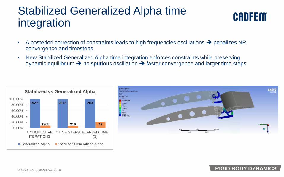
Stabilized Generalized Alpha time integration
• A posteriori correction of constraints leads to high frequencies oscillations ➔ penalizes NR convergence and timesteps
• New Stabilized Generalized Alpha time integration enforces constraints while preserving dynamic equilibrium ➔ no spurious oscillation ➔ faster convergence and larger time steps
15271 2916 203
1305 216 430.00%
20.00%
40.00%
60.00%
80.00%
100.00%
# CUMULATIVE ITERATIONS
# TIME STEPS ELAPSED TIME (S)
Stabilized vs Generalized Alpha
Generalized Alpha Stabilized Generalized Alpha
RIGID BODY DYNAMICS
© CADFEM (Suisse) AG, 2019
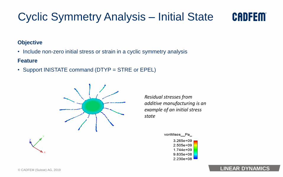
Residual stresses from additive manufacturing is an example of an initial stress state
Cyclic Symmetry Analysis – Initial State
Objective
• Include non-zero initial stress or strain in a cyclic symmetry analysis
Feature
• Support INISTATE command (DTYP = STRE or EPEL)
LINEAR DYNAMICS

© CADFEM (Suisse) AG, 2019
Acoustics & NVH
132

© CADFEM (Suisse) AG, 2019
Maxwell LF Analysis Harmonic Analysis
Transfer Forces Generate ERP and Waterfall plot
Harmonic Acoustic Analysis
Noise-Vibration and Acoustic Modeling for Electrical Machines
Spe
ed
(rp
m)
Acoustic Frequency (Hz)
Multiple RPM

© CADFEM (Suisse) AG, 2019
Maxwell-Mechanical: Multiple RPMs & ERP Waterfall Diagram
• Two mapping strategies available depending on the geometry compliance:
✓ Object Based: Integrated Forces / Moments
✓ Mesh Based: Surface Force Densities
ACOUSTICS

© CADFEM (Suisse) AG, 2019
Export Results to XML format for VRXP Sound Dimension (Beta)
• Allows XML export for Equivalent Radiated Power and Sound Power Level. XML file can be read in Optis VRXP Sound Dimension to synthesize the sound and create a .WAV file.
Listen to computed
ERP
ACOUSTICS

© CADFEM (Suisse) AG, 2019
Workbench LS-DYNA
136

© CADFEM (Suisse) AG, 2019
Body Interactions of Type Reinforcement
• Body Interactions with type reinforcement are now available with LS-DYNA. They allow modeling of reinforced solid structures, like
• reinforced concrete.
• Nodes in the reinforcement beams and the matrix in which they sit do not have to be coincident.
LS-DYNA

© CADFEM (Suisse) AG, 2019
Imported Temperature
• Transfer links have been enabled between steady state thermal , transient thermal calculations and Workbench LS-DYNA, allowing to transfer body temperatures from a thermal calculation to Workbench LS-DYNA.
• Temperature induced deformations can now be taken account in a LS-DYNA explicit calculation
LS-DYNA

© CADFEM (Suisse) AG, 2019
Deformation Transfer
• The deformation from a Workbench LS-DYNA calculation , can now be transferred to downstream systems , like Static Structural , allowing a user to initiate those simulations from a deformed state.
LS-DYNA
© CADFEM (Suisse) AG, 2019
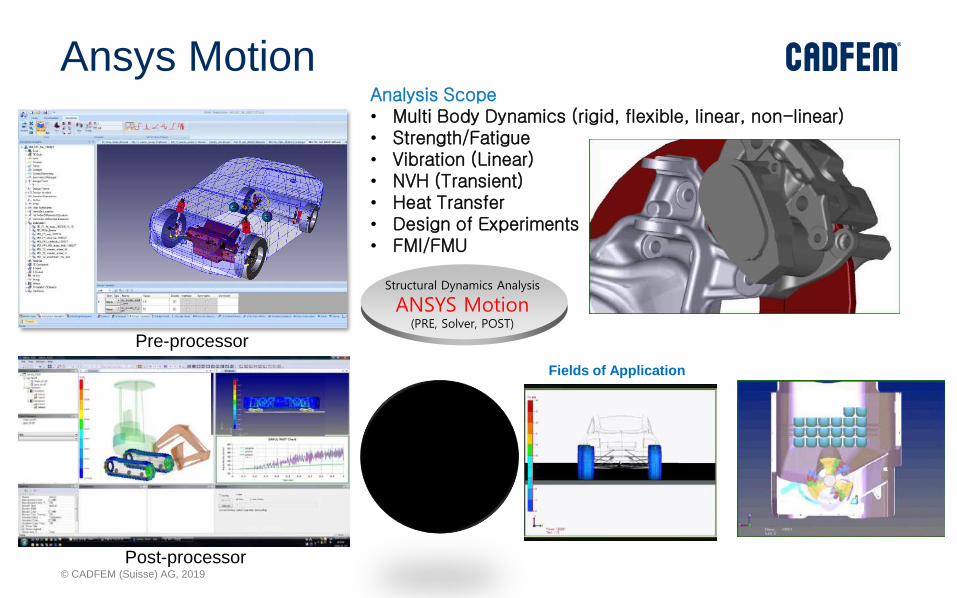
Structural Dynamics Analysis
ANSYS Motion(PRE, Solver, POST)
Analysis Scope• Multi Body Dynamics (rigid, flexible, linear, non-linear)• Strength/Fatigue• Vibration (Linear)• NVH (Transient)• Heat Transfer• Design of Experiments• FMI/FMU
Fields of Application
Pre-processor
Post-processor
Ansys Motion

© CADFEM (Suisse) AG, 2019
• Analysis Purpose• Evaluation of hydro actuator performance of mini loader using
FMI method.
• Major characteristics• Ansys Motion calculates the load and Systemsimulation
calculates the speed.
• Develop a model• Vehicle and Structure models are modeled as ANSYS Motion.
• Hydraulic circuit and driver models are modeled as
Systemsimulation.
• Data exchange between ANSYS Motion and Systemsimulation is
done through FMI
• Simulation Results• Strokes of Bucket and Boom is well matched with input strokes.
• Loads required to represent strokes of bucket and boom were
calculated.
ANSYS Motion - Hydraulic System Performance with FMI

© CADFEM (Suisse) AG, 2019
Whine of an E-Axle Cont…• Simulation Results
• The color map which is created by the acceleration data shows the whine noise of GMF and MF.
• The harmonics of GMF and MF are shown well.
• Motor excitation force is estimated as the main noise source of the system.
• The noise of the 1st gear set is higher than that of 2nd gear set.
• The vibrations of system modes are shown at the specific frequencies.
< Order tracking>
<Tooth Pressure(1st)>
<Tooth Pressure(2nd)>
GMF1
GMF2
MF2
MF1
System Mode1
System Mode2
< Color Map(STFT)>
< Z Acceleration raw data >
GMF : Gear Mesh Frequency
MF : Motor Frequency
© CADFEM (Suisse) AG, 2019
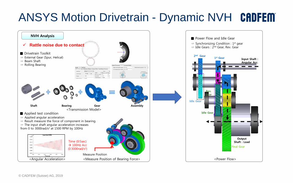
ANSYS Motion Drivetrain - Dynamic NVH
NVH Analysis■ Power Flow and Idle Gear
☞ Synchronizing Condition : 1st gear☞ Idle Gears : 2nd Gear, Rev. Gear
<Power Flow>
Input Shaft : Angular Acc.
1st Gear2nd Gear
Final Gear
Rev. Gear
Output Shaft : Load
Idle Gear
Idle Gear
■ Drivetrain Toolkit☞ External Gear (Spur, Helical) ☞ Beam Shaft☞ Rolling Bearing
■ Applied test condition☞ Applied angular acceleration☞ Result measure the force of component in bearing.☞ The input shaft angular acceleration increases from 0 to 3000rad/s2 at 1500 RPM by 100Hz
Measure Position
<Angular Acceleration> <Measure Position of Bearing Force>
<Transmission Model>Shaft Bearing Gear Assembly
Time (0:5sec)→ 100Hz Acc(0:3000rad/s2)
✓ Rattle noise due to contact

© CADFEM (Suisse) AG, 2019
ANSYS Motion – Features
• Rigid / Flexible Body Dynamics:• Rigid• Flexible: Mesh-Free• Flexible: Modal (CMS)• Flexible: Full (FE-Formulation)
• Complex Contact treatment:• Rigid Rigid• Rigid Flexible• Flexible Flexible
• Advanced features:• Tire model• Gears• Chains• Belts• CVT-elements• Point/Curve contact idealisation• Curve/Curve contact idealisation
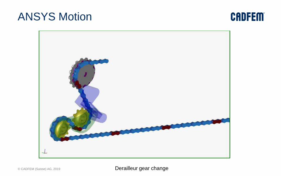
© CADFEM (Suisse) AG, 2019 Derailleur gear change
ANSYS Motion

© CADFEM (Suisse) AG, 2019
MAPDL

© CADFEM (Suisse) AG, 2019
Base element
=
Reinforced element
THERMAL REINFORCING: Basic Approach
• Use reduced order model for the embedded metal regions – line / plate elements
• Use Reinf Technology to capture the thermal solution by embedding the line/plate
• Elements in a base element
MAPDL ELEMENTS
© CADFEM (Suisse) AG, 2019
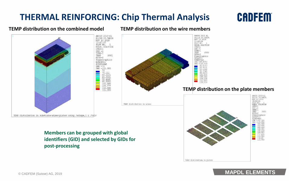
THERMAL REINFORCING: Chip Thermal AnalysisTEMP distribution on the combined model TEMP distribution on the wire members
TEMP distribution on the plate members
Members can be grouped with global identifiers (GID) and selected by GIDs for post-processing
MAPDL ELEMENTS
© CADFEM (Suisse) AG, 2019
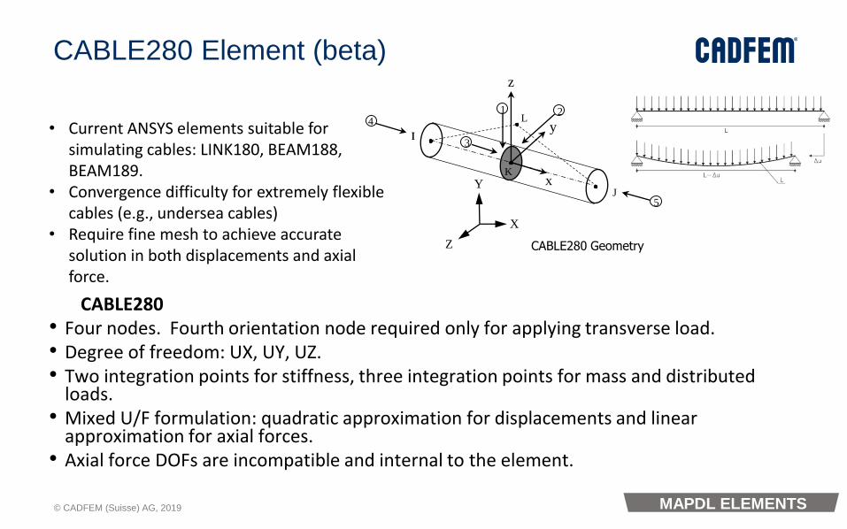
CABLE280 Element (beta)z
II
J
K
Ly
x
1 2
3
4
5
Y
X
Z CABLE280 Geometry
• Current ANSYS elements suitable for simulating cables: LINK180, BEAM188, BEAM189.
• Convergence difficulty for extremely flexible cables (e.g., undersea cables)
• Require fine mesh to achieve accurate solution in both displacements and axial force.
CABLE280• Four nodes. Fourth orientation node required only for applying transverse load.• Degree of freedom: UX, UY, UZ.• Two integration points for stiffness, three integration points for mass and distributed
loads.• Mixed U/F formulation: quadratic approximation for displacements and linear
approximation for axial forces.• Axial force DOFs are incompatible and internal to the element.
MAPDL ELEMENTS

© CADFEM (Suisse) AG, 2019
Commands enhancement for Issuing solve command
• Replaces: *abbr, solve, alls
LINEAR DYNAMICS
© CADFEM (Suisse) AG, 2019
Modèles «runtime" pour les jumeaux numériques

© CADFEM (Suisse) AG, 2019
ANSYS Twin Builder
Build an accurate
Physics-Based
Digital Twin
in record time
Connect the
Twins
to IIoT Platforms
and Deploy Run
times
In Operation
Validate and
Optimize
the Twin
System Simulation
System Validation & Optimization
System Predictive Maintenance
152

© CADFEM (Suisse) AG, 2019
Linear ROMS Non-linear, Static Non-linear, Dynamic
Techniques
State-Space/LTI
Modal
S-Parameter
DX-ROM
Static ROM
OptiSLang
Twin Builder Dynamic
ROM Builder
Supported
Tools
Fluent, Mechanical, Icepak,
Q3D, Maxwell, HFSS, SIwave
Static ROM: Fluent
DX-ROM: Workbench/DesignXplorerAll
Limitation
Linear system only.
Specific limitation for each
tool
Support enabled by tool
Static only
Extending support for new tools
requires effort
For Scalar only.
Limited input and outputs
There are three major groups of ROMs supported by Twin Builder
© CADFEM (Suisse) AG, 2019
1. Static ROM
© CADFEM (Suisse) AG, 2019
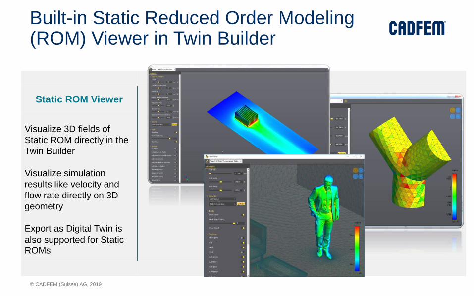
Static ROM Viewer
Visualize 3D fields of
Static ROM directly in the
Twin Builder
Visualize simulation
results like velocity and
flow rate directly on 3D
geometry
Export as Digital Twin is
also supported for Static
ROMs
Built-in Static Reduced Order Modeling (ROM) Viewer in Twin Builder

© CADFEM (Suisse) AG, 2019
Static ROM – WF in ANSYS WB (only forFlunet avilable)
To specify the Fluent's parallel number, change the Property of the Setup cell
After DOE is updated, then update ROM Builder component
1
2
3

© CADFEM (Suisse) AG, 2019
Demo - Fluid/Solid Coupled Heat Transfer
• Two inlets
• Main inlet:constant velocityconstant temperature
• Secondary inlet:velocity excitationtemperature excitation
• One outlet
• 1.6M cells
• water steam at 20bar and pipe from steel
• Ideal gas
• k-e model with scalable wall functions
• Each Fluent calculation is ~57h on 16 cores
• Goal : Dynamic ROM on 2 scalar criteria with respect to the 2 excitations
• T_solid = mean temperature in solid outlet
Secondary inlet Excitations : temperature & velocity
Main Inlet:Constant temperatureConstant velocity
© CADFEM (Suisse) AG, 2019
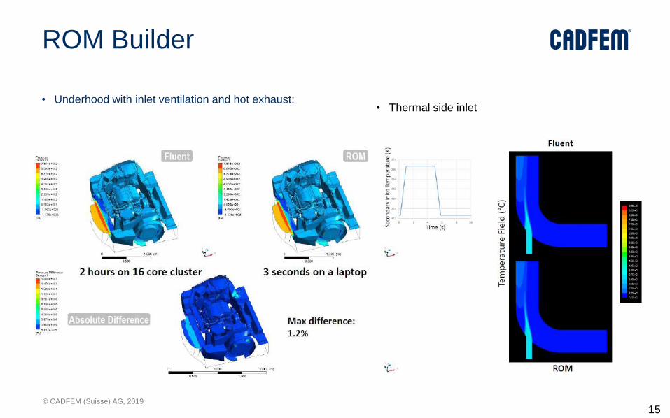
ROM Builder
• Underhood with inlet ventilation and hot exhaust:
15
8
• Thermal side inlet
© CADFEM (Suisse) AG, 2019
2. DX ROM
© CADFEM (Suisse) AG, 2019
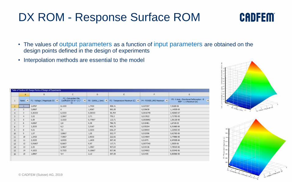
DX ROM - Response Surface ROM
• The values of output parameters as a function of input parameters are obtained on the design points defined in the design of experiments
• Interpolation methods are essential to the model
© CADFEM (Suisse) AG, 2019
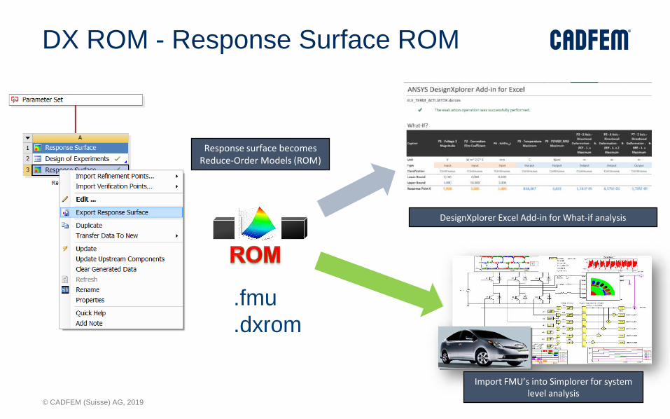
DX ROM - Response Surface ROM
DesignXplorer Excel Add-in for What-if analysis
Import FMU’s into Simplorer for system level analysis
Response surface becomes Reduce-Order Models (ROM)
.fmu
.dxrom
© CADFEM (Suisse) AG, 2019
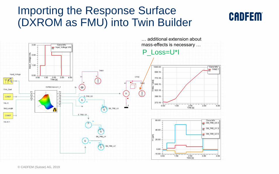
Importing the Response Surface (DXROM as FMU) into Twin Builder
P_Loss=U*I
… additional extension about
mass-effects is necessary …
© CADFEM (Suisse) AG, 2019
2. Dynamic ROM

© CADFEM (Suisse) AG, 2019
Dynamic ROM Builder available in Twin Builder in 2019 R1
Dynamic ROM
Support for building
Dynamic ROMs in Twin
Builder
UI for ROM building
and visualization
results
Exportable as Digital
Twin

© CADFEM (Suisse) AG, 2019
Demo – nonlinear transient simulation of coil-system
• Coil System – FEM-Modell
INPUT:
Heat OUTPUT:
Core Temp
OUTPUT:
Coil Temp
© CADFEM (Suisse) AG, 2019
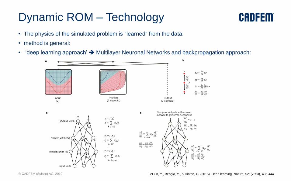
Dynamic ROM – Technology
• The physics of the simulated problem is "learned" from the data.
• method is general:
• ‘deep learning approach’ ➔ Multilayer Neuronal Networks and backpropagation approach:
LeCun, Y., Bengio, Y., & Hinton, G. (2015). Deep learning. Nature, 521(7553), 436-444

© CADFEM (Suisse) AG, 2019
Dynamic ROM Generation Prozess
© CADFEM (Suisse) AG, 2019
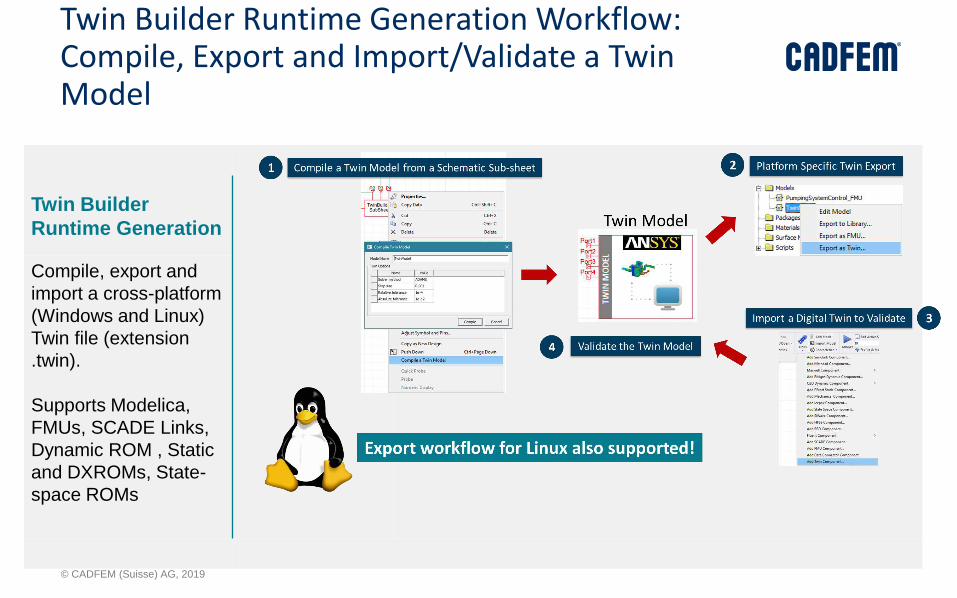
Twin Builder Runtime Generation Workflow: Compile, Export and Import/Validate a Twin Model
Twin Builder
Runtime Generation
Compile, export and
import a cross-platform
(Windows and Linux)
Twin file (extension
.twin).
Supports Modelica,
FMUs, SCADE Links,
Dynamic ROM , Static
and DXROMs, State-
space ROMs
© CADFEM (Suisse) AG, 2019
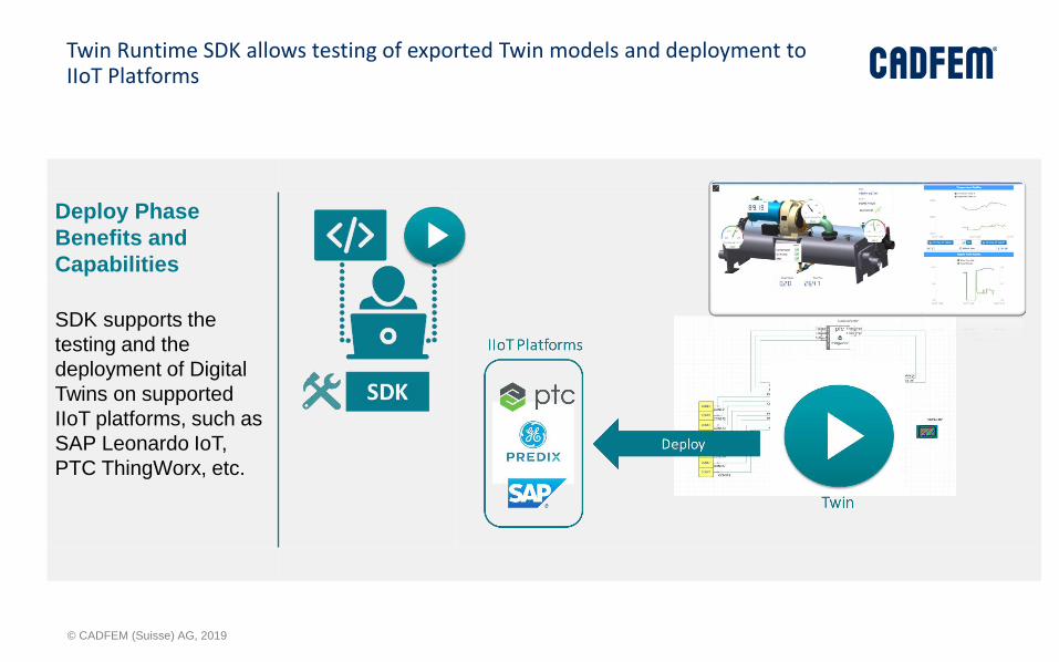
Twin Runtime SDK allows testing of exported Twin models and deployment to IIoT Platforms
Deploy Phase
Benefits and
Capabilities
SDK supports the
testing and the
deployment of Digital
Twins on supported
IIoT platforms, such as
SAP Leonardo IoT,
PTC ThingWorx, etc.

© CADFEM (Suisse) AG, 2019
Other Tools

© CADFEM (Suisse) AG, 2019
Preprocessing –
(Alpha / 2019 R3) Avoid hanging nodes
Mosaic conformally connects the
1:8 hexcore cell size jump –
Ensure accurate results

© CADFEM (Suisse) AG, 2019
Improved User Experience –
Single-window workflow (beta)
Geometry Surface Mesh Region Extract Volume Mesh Setup/Solve Post
SpaceClaim

© CADFEM (Suisse) AG, 2019
EM
Maxwell:
• Custom geometry import to RMxprt
• 2-way coupling:
• Maxwell-Eddy <-> Fluent transient
• Maxwell <-> Icepak (in AEDT)
• Noise Vibration Harshness (NVH) (Maxwell transient -> Mechanical)
SIwave:
• EMI Scanner – quickly scan entire design for rules violation which could cause EMI problems
HFSS:
• Antenna blockage support for HFSS SBR+
• Full Assembly: ECAD + MCAD Mesh Assembly
Induction Coil with Resulting
Core Temperature Distribution
3D Layout 3D Layout: Full AssemblyMCAD
Geometry changes can quickly be implemented, adaptive meshing gives confidence on every solution without user interaction
© CADFEM (Suisse) AG, 2019
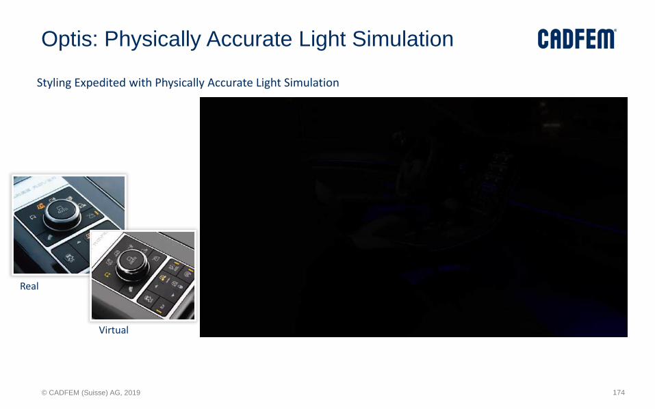
Optis: Physically Accurate Light Simulation
Real
Virtual
Styling Expedited with Physically Accurate Light Simulation
174

© CADFEM (Suisse) AG, 2019
Autonomous Vehicles
Traditional Rendering Engine ANSYS’s Physically Accurate Simulation
ANSYS’s physically accurate driving scenario simulations conduct the most realistic AD systems validations
175
© CADFEM (Suisse) AG, 2019
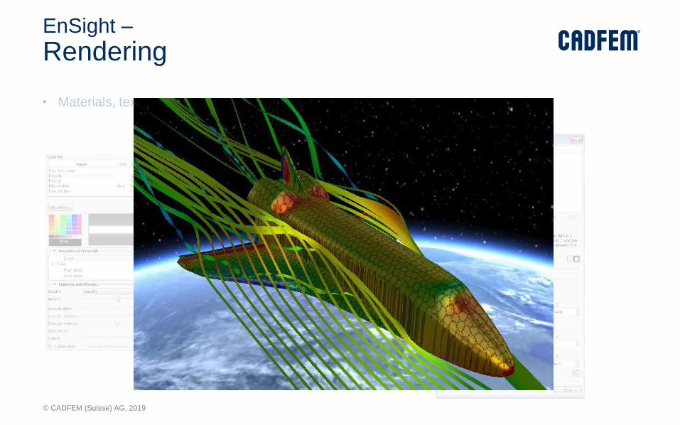
EnSight –
Rendering
• Materials, textures
• Lighting Effects

© CADFEM (Suisse) AG, 2019
• Stereo:
• 3d monitor/projector (min 120 fps) and shutter-goggles required. Activate stereo mode and continue post-processing.
• Virtual Reality:
EnSight –
Stereo / Virtual Reality

© CADFEM (Suisse) AG, 2019
Rocky
© CADFEM (Suisse) AG, 2019
combining fibers, shells and solids

© CADFEM (Suisse) AG, 2019
Flexible fiber: accurate stress-strain response

© CADFEM (Suisse) AG, 2019
Flexible fibers with CFD coupling

© CADFEM (Suisse) AG, 2019
New multi-body motion capabilities

© CADFEM (Suisse) AG, 2019
Extended ANSYS CFD COUPLING FUNCTIONALITY
• Multiple domains COFFEE ROASTING MACHINECourtesy of
Moving/Non-conformal meshes
© CADFEM (Suisse) AG, 2019
Prochains événements CADFEM
Restez informés
1
8
Restez informés
© CADFEM (Suisse) AG, 2019
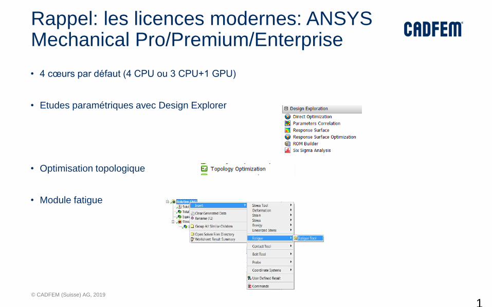
Rappel: les licences modernes: ANSYS Mechanical Pro/Premium/Enterprise
• 4 cœurs par défaut (4 CPU ou 3 CPU+1 GPU)
• Etudes paramétriques avec Design Explorer
• Optimisation topologique
• Module fatigue
1
8
© CADFEM (Suisse) AG, 2019
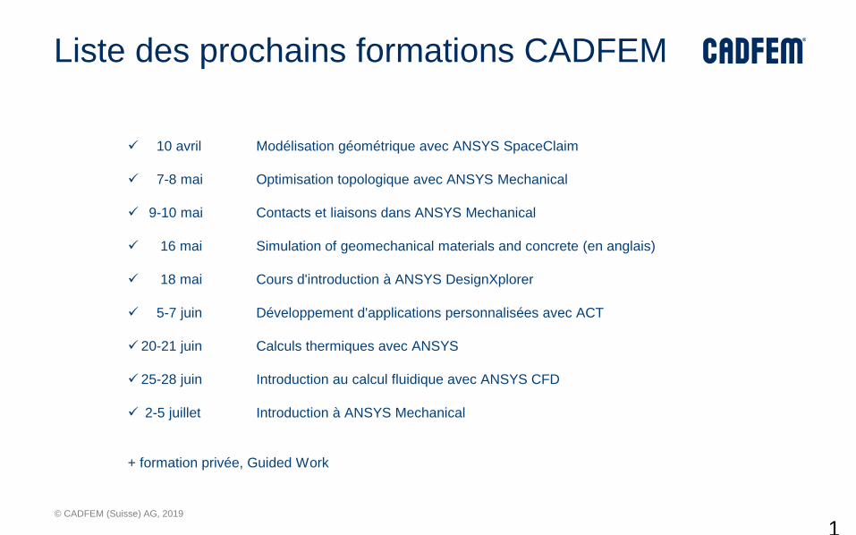
Liste des prochains formations CADFEM
1
8
✓ 10 avril Modélisation géométrique avec ANSYS SpaceClaim
✓ 7-8 mai Optimisation topologique avec ANSYS Mechanical
✓ 9-10 mai Contacts et liaisons dans ANSYS Mechanical
✓ 16 mai Simulation of geomechanical materials and concrete (en anglais)
✓ 18 mai Cours d'introduction à ANSYS DesignXplorer
✓ 5-7 juin Développement d'applications personnalisées avec ACT
✓ 20-21 juin Calculs thermiques avec ANSYS
✓ 25-28 juin Introduction au calcul fluidique avec ANSYS CFD
✓ 2-5 juillet Introduction à ANSYS Mechanical
+ formation privée, Guided Work
© CADFEM (Suisse) AG, 2019
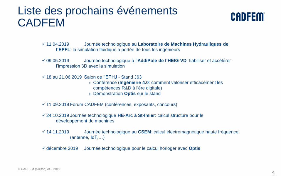
Liste des prochains événements CADFEM
1
8
✓ 11.04.2019 Journée technologique au Laboratoire de Machines Hydrauliques de
l’EPFL: la simulation fluidique à portée de tous les ingénieurs
✓ 09.05.2019 Journée technologique à l’AddiPole de l’HEIG-VD: fiabiliser et accélérer
l’impression 3D avec la simulation
✓ 18 au 21.06.2019 Salon de l’EPHJ - Stand J63
o Conférence (Ingénierie 4.0: comment valoriser efficacement les
compétences R&D à l'ère digitale)
o Démonstration Optis sur le stand
✓ 11.09.2019 Forum CADFEM (conférences, exposants, concours)
✓ 24.10.2019 Journée technologique HE-Arc à St-Imier: calcul structure pour le
développement de machines
✓ 14.11.2019 Journée technologique au CSEM: calcul électromagnétique haute fréquence
(antenne, IoT,…)
✓ décembre 2019 Journée technologique pour le calcul horloger avec Optis

© CADFEM (Suisse) AG, 2019
Prochains événements CADFEM sur le site web
1
8
https://www.cadfem.ch/fr/evenements.html
© CADFEM (Suisse) AG, 2019
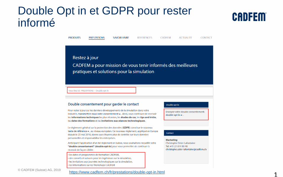
Double Opt in et GDPR pour rester informé
1
8
https://www.cadfem.ch/fr/prestations/double-opt-in.html

© CADFEM (Suisse) AG, 2019
Double Opt in processus
1
9
Email: cliquez sur le lien pour terminer
le processus de confirmation