Road vehicles — Environmental conditions and testing for...
20
Reference number ISO 16750-1:2006(E) INTERNATIONAL STANDARD ISO 16750-1 Second edition 2006-08-01 Road vehicles — Environmental conditions and testing for electrical and electronic equipment — Part 1: General Véhicules routiers — Spécifications d'environnement et essais de l'équipement électrique et électronique — Partie 1: Généralités No reproduction or networking permitted without license from IHS --`,,```,,,,````-`-`,,`,,`,`,,`---
Transcript of Road vehicles — Environmental conditions and testing for...
Reference numberISO 16750-1:2006(E)
© ISO 2006
INTERNATIONAL STANDARD
ISO16750-1
Second edition2006-08-01
Road vehicles — Environmental conditions and testing for electrical and electronic equipment — Part 1: General
Véhicules routiers — Spécifications d'environnement et essais de l'équipement électrique et électronique —
Partie 1: Généralités
Copyright International Organization for Standardization Provided by IHS under license with ISO
Not for ResaleNo reproduction or networking permitted without license from IHS
--`,,```,,,,````-`-`,,`,,`,`,,`---
ISO 16750-1:2006(E)
PDF disclaimer This PDF file may contain embedded typefaces. In accordance with Adobe's licensing policy, this file may be printed or viewed but shall not be edited unless the typefaces which are embedded are licensed to and installed on the computer performing the editing. In downloading this file, parties accept therein the responsibility of not infringing Adobe's licensing policy. The ISO Central Secretariat accepts no liability in this area.
Adobe is a trademark of Adobe Systems Incorporated.
Details of the software products used to create this PDF file can be found in the General Info relative to the file; the PDF-creation parameters were optimized for printing. Every care has been taken to ensure that the file is suitable for use by ISO member bodies. In the unlikely event that a problem relating to it is found, please inform the Central Secretariat at the address given below.
© ISO 2006 All rights reserved. Unless otherwise specified, no part of this publication may be reproduced or utilized in any form or by any means, electronic or mechanical, including photocopying and microfilm, without permission in writing from either ISO at the address below or ISO's member body in the country of the requester.
ISO copyright office Case postale 56 • CH-1211 Geneva 20 Tel. + 41 22 749 01 11 Fax + 41 22 749 09 47 E-mail [email protected] Web www.iso.org
Published in Switzerland
ii © ISO 2006 – All rights reserved
Copyright International Organization for Standardization Provided by IHS under license with ISO
Not for ResaleNo reproduction or networking permitted without license from IHS
--`,,```,,,,````-`-`,,`,,`,`,,`---
ISO 16750-1:2006(E)
© ISO 2006 – All rights reserved iii
Contents Page
Foreword............................................................................................................................................................ iv Introduction ........................................................................................................................................................ v 1 Scope ..................................................................................................................................................... 1 2 Normative references ........................................................................................................................... 1 3 Terms and definitions........................................................................................................................... 1 4 Classification by mounting location ................................................................................................... 3 4.1 Engine compartment ............................................................................................................................ 3 4.2 Passenger compartment ...................................................................................................................... 3 4.3 Luggage compartment/load compartment......................................................................................... 3 4.4 Mounting on the exterior/in cavities ................................................................................................... 3 4.5 Other mounting locations .................................................................................................................... 4 5 Operating modes .................................................................................................................................. 4 5.1 Operating mode 1 ................................................................................................................................. 4 5.2 Operating mode 2 ................................................................................................................................. 4 5.3 Operating mode 3 ................................................................................................................................. 4 6 Functional status classification .......................................................................................................... 4 6.1 General................................................................................................................................................... 4 6.2 Class A................................................................................................................................................... 5 6.3 Class B................................................................................................................................................... 5 6.4 Class C................................................................................................................................................... 5 6.5 Class D................................................................................................................................................... 5 6.6 Class E ................................................................................................................................................... 5 7 Tests and requirements ....................................................................................................................... 5 7.1 General................................................................................................................................................... 5 7.2 General test conditions........................................................................................................................ 5 7.3 Test sequence ....................................................................................................................................... 6 8 Designation ........................................................................................................................................... 6 8.1 Coding.................................................................................................................................................... 6 8.2 Use of Code Z “as agreed” .................................................................................................................. 7 Annex A (informative) Example for a test sequence plan .............................................................................. 8 Annex B (informative) Example of life test/statement of reliability............................................................... 9
Copyright International Organization for Standardization Provided by IHS under license with ISO
Not for ResaleNo reproduction or networking permitted without license from IHS
--`,,```,,,,````-`-`,,`,,`,`,,`---
ISO 16750-1:2006(E)
iv © ISO 2006 – All rights reserved
Foreword
ISO (the International Organization for Standardization) is a worldwide federation of national standards bodies (ISO member bodies). The work of preparing International Standards is normally carried out through ISO technical committees. Each member body interested in a subject for which a technical committee has been established has the right to be represented on that committee. International organizations, governmental and non-governmental, in liaison with ISO, also take part in the work. ISO collaborates closely with the International Electrotechnical Commission (IEC) on all matters of electrotechnical standardization.
International Standards are drafted in accordance with the rules given in the ISO/IEC Directives, Part 2.
The main task of technical committees is to prepare International Standards. Draft International Standards adopted by the technical committees are circulated to the member bodies for voting. Publication as an International Standard requires approval by at least 75 % of the member bodies casting a vote.
Attention is drawn to the possibility that some of the elements of this document may be the subject of patent rights. ISO shall not be held responsible for identifying any or all such patent rights.
ISO 16750-1 was prepared by Technical Committee ISO/TC 22, Road vehicles, Subcommittee SC 3, Electrical and electronic equipment.
This second edition cancels and replaces the first edition (ISO 16750-1:2003), which has been technically revised.
ISO 16750 consists of the following parts, under the general title Road vehicles — Environmental conditions and testing for electrical and electronic equipment:
⎯ Part 1: General
⎯ Part 2: Electrical loads
⎯ Part 3: Mechanical loads
⎯ Part 4: Climatic loads
⎯ Part 5: Chemical loads
Copyright International Organization for Standardization Provided by IHS under license with ISO
Not for ResaleNo reproduction or networking permitted without license from IHS
--`,,```,,,,````-`-`,,`,,`,`,,`---
ISO 16750-1:2006(E)
© ISO 2006 – All rights reserved v
Introduction
The concept of ISO 16750 is to assist its user in systematically defining and/or applying a set of internationally accepted environmental conditions, tests and operating requirements, which are based on the anticipated actual environment in which the equipment will be operated in and exposed to during its life cycle.
The following environmental factors have been considered in the development of this ISO 16750.
⎯ World geography and climate
Road vehicles are owned and operated in nearly all land regions of the earth. Significant variation in environmental conditions due to climatic environment, including diurnal and seasonal cycles, can therefore be expected. Consideration has been given to worldwide ranges in temperature, humidity, precipitation and atmospheric conditions including dust, pollution and altitude.
⎯ Type of vehicle
Environmental conditions in and on road vehicles can depend on vehicle design attributes, such as engine type, engine size, suspension characteristics, vehicle mass, vehicle size, electrical supply voltage and so on. Consideration has been given to typical types of vehicles including commercial (heavy) trucks, passenger cars and trucks and diesel and gasoline engines.
⎯ Vehicle use conditions and operating modes
Environmental conditions in and on the vehicle vary significantly with road quality, type of road surface, road topography, vehicle use (e.g. commuting, towing, cargo transport, etc.) and driving habit. Operating modes, such as storage, starting, driving, stopping and so on, have been considered.
⎯ Equipment life cycle
Electrical and electronic equipment are also resistant to environmental conditions experienced during manufacture, shipping, handling, storage, vehicle assembly and vehicle maintenance and repair. Such conditions and test (e.g. handling drop test) are within the scope of ISO 16750.
⎯ Vehicle supply voltage
Supply voltage varies with vehicle use, operating mode, electrical distribution system design and even climatic conditions. Faults within the vehicle electrical system, such as overvoltage alternator and intermittencies in connection systems, may occur. Such conditions are within the scope of ISO 16750.
⎯ Mounting location in the vehicle
In current or future car concepts, systems/components are mounted in almost any location of the car. The environmental requirements for each specific application highly depend on its mounting location. Each location in a car has its distinct set of environmental loads. As an example, the range of temperatures in the engine compartment differs significantly from the range in the passenger compartment. This is also true for the vibration loads. But in this case, not only the vibration levels are different, the type of vibration load also varies. Body mount components are typically exposed to random vibrations whereas for engine mount systems/components the additional sine vibration from the engine is considered. Devices installed in doors are exposed to a high number of mechanical shocks from door slamming additionally.
It is desirable for the car manufacturer to group the different environmental load types and levels in a reasonable number of standard requirement sets. This strategy makes it possible to carry systems/components from one car project to another. Furthermore, the exact requirement levels are often unknown when designing a component for a future car concept. The expected environmental loads are usually compiled from other car concepts with similar conditions. The grouping is normally done by mounting location, but it is difficult to define the right number of different mounting locations and respective load profiles,
Copyright International Organization for Standardization Provided by IHS under license with ISO
Not for ResaleNo reproduction or networking permitted without license from IHS
--`,,```,,,,````-`-`,,`,,`,`,,`---
ISO 16750-1:2006(E)
vi © ISO 2006 – All rights reserved
because there is a conflict of aims between having only few requirement classes and tailoring to the requirement levels for each application. The reason is that the environmental loads are not only depending on the mounting location. There are other major factors that effect the stress levels for systems/components. For examples, body styles, drive-train concepts or package densities can create absolutely different requirement levels for devices that are installed in different cars at almost the same location.
The concept of ISO 16750 is to define requirement classes for separate load types. It distinguishes between electrical, mechanical, thermal, climatic and chemical loads. For each load type, several requirement classes are defined. Every requirement class is determined by a specific code letter. The complete environmental requirement set is created by defining the code letter combination. The code letters are defined in the respective clauses of this part of ISO 16750. Additionally, tables in the annexes of each part consists of usual mounting locations and define examples of their respective code letters. For normal applications, these code letters are used. If an application is very specific and therefore the given code letter combinations can not be used, it is possible to create new code letter combinations to serve this purpose. In case none of the given code letters is useable, new requirement levels can be created by using the code letter Z. In this case, the specific requirements need to be defined separately, but it is desirable not to change the test methods.
It is recommended to consider at least the following mounting locations for a device under test (DUT) with respect to thermal, mechanical, climatic and chemical load.
a) Applicability to manufacturers responsibility
Due to technology limitations or variations in vehicle design, the vehicle manufacturer may be required to place a component in a location where it cannot withstand the environmental conditions described in ISO 16750. Under these circumstances, it is the responsibility of the vehicle manufacturer to provide the necessary environmental protection.
b) Applicability to wiring harnesses, cables and electrical connectors
Although some environmental conditions and tests in ISO 16750 may be relevant to vehicle wiring harnesses, cables and connectors, its scope is not sufficient to be used as a complete standard. It is therefore not recommended that ISO 16750 be directly applied to such devices and equipment. Applicable standards are taken into account.
c) Applicability to parts or assemblies in or on equipment
ISO 16750 describes environmental conditions and tests to be applied to electrical and electronic equipment directly mounted in or on the vehicle. It is not intended for direct application to parts or assemblies that are part of the equipment. For example, ISO 16750 should not be directly applied to integrated circuits (ICs) and discrete components, electrical connectors, printed circuit boards (PCBs), gauges, displays, controls, etc. that are attached in or on the equipment. Electrical, mechanical, climatic and chemical loads for such parts and assemblies can be quite different from those described in ISO 16750.
On the other hand, it is desirable to use ISO 16750 to help derive environmental conditions and test requirements for parts and assemblies that are intended for use in road vehicle equipment. For example, a temperature range of −40 °C to 90 °C may be specified for an assembly contained inside a piece of equipment having a temperature range of −40 °C to 70 °C and a temperature rise of 20 °C.
d) Applicability relative to system integration and validation
The user of ISO 16750 is cautioned to understand that the scope of ISO 16750 is limited to conditions and testing at the equipment level, and therefore does not represent all conditions and testing necessary for complete verification and validation of the vehicle system. Environmental and reliability testing of equipment parts and vehicle systems may be required.
For example, ISO 16750 does not necessarily ensure that environmental and reliability requirements for solder joints, solderless connections, integrated circuits, and so on are met. Such items are assured at the part, material or assembly level. Likewise, vehicle and system level testing is required to validate the equipment in the vehicle application.
Copyright International Organization for Standardization Provided by IHS under license with ISO
Not for ResaleNo reproduction or networking permitted without license from IHS
--`,,```,,,,````-`-`,,`,,`,`,,`---
INTERNATIONAL STANDARD ISO 16750-1:2006(E)
© ISO 2006 – All rights reserved 1
Road vehicles — Environmental conditions and testing for electrical and electronic equipment —
Part 1: General
1 Scope
This part of ISO 16750 applies to electric and electronic systems/components for vehicles. It describes the potential environmental stresses and specifies tests and requirements recommended for the specific mounting location on/in the vehicle.
This part of ISO 16750 contains definitions and general notes. Electromagnetic compatibility (EMC) is not covered by this part of ISO 16750.
2 Normative references
The following referenced documents are indispensable for the application of this document. For dated references, only the edition cited applies. For undated references, the latest edition of the referenced document (including any amendments) applies.
ISO 16750-2, Road vehicles — Environmental conditions and testing for electrical and electronic equipment — Part 2: Electrical loads
ISO 16750-3, Road vehicles — Environmental conditions and testing for electrical and electronic equipment — Part 3: Mechanical loads
ISO 16750-4, Road vehicles — Environmental conditions and testing for electrical and electronic equipment — Part 4: Climatic loads
ISO 16750-5, Road vehicles — Environmental conditions and testing for electrical and electronic equipment — Part 5: Chemical loads
ISO 20653, Road vehicles — Degrees of protection (IP-Code) — Protection of electrical equipment against foreign objects, water and access
3 Terms and definitions
For the purposes of this document, the following terms and definitions apply.
3.1 nominal voltage UN voltage value used to describe the electrical system of a vehicle
3.2 supply voltage US voltage of the electrical system of a vehicle that varies with the system load and the operating condition of the generator
Copyright International Organization for Standardization Provided by IHS under license with ISO
Not for ResaleNo reproduction or networking permitted without license from IHS
--`,,```,,,,````-`-`,,`,,`,`,,`---
ISO 16750-1:2006(E)
2 © ISO 2006 – All rights reserved
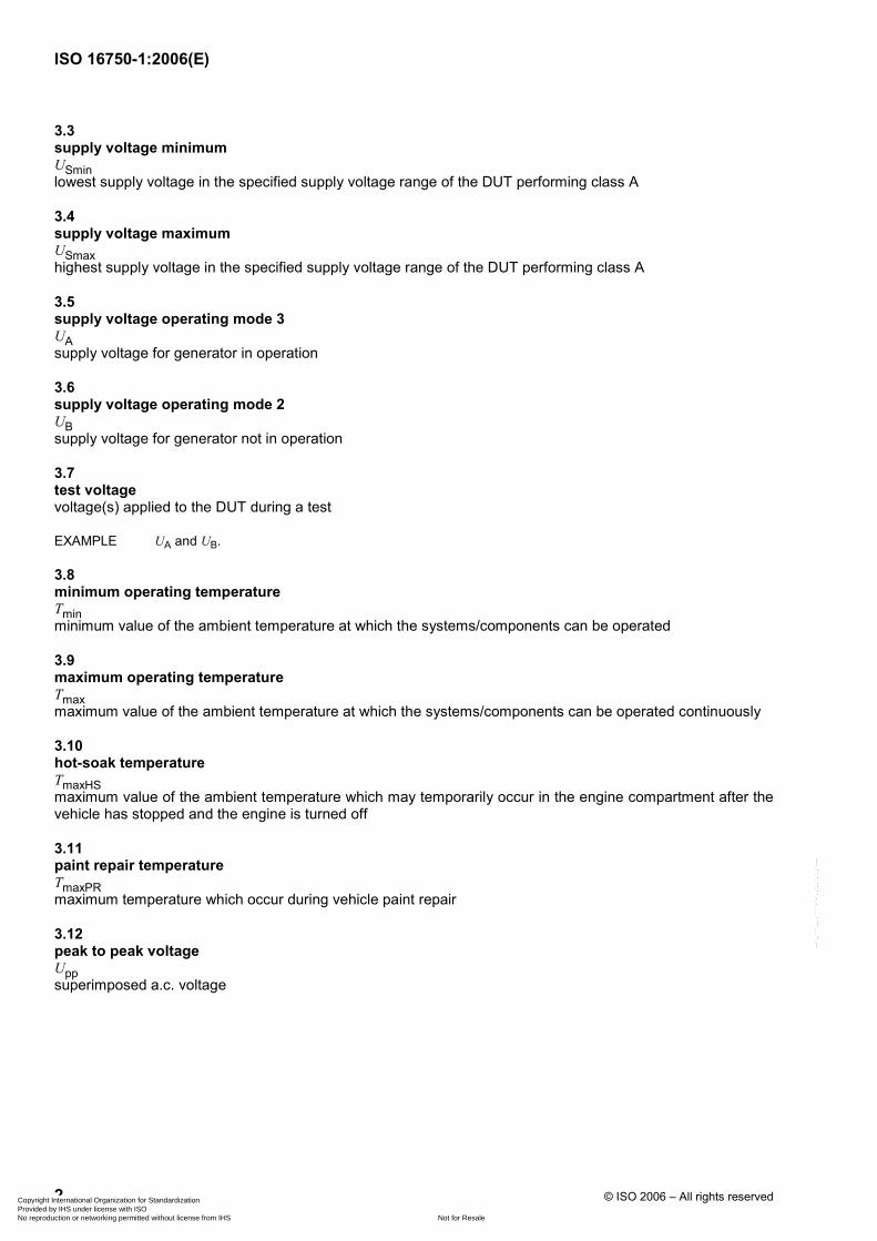
3.3 supply voltage minimum USmin lowest supply voltage in the specified supply voltage range of the DUT performing class A
3.4 supply voltage maximum USmax highest supply voltage in the specified supply voltage range of the DUT performing class A
3.5 supply voltage operating mode 3 UA supply voltage for generator in operation
3.6 supply voltage operating mode 2 UB supply voltage for generator not in operation
3.7 test voltage voltage(s) applied to the DUT during a test
EXAMPLE UA and UB.
3.8 minimum operating temperature Tmin minimum value of the ambient temperature at which the systems/components can be operated
3.9 maximum operating temperature Tmax maximum value of the ambient temperature at which the systems/components can be operated continuously
3.10 hot-soak temperature TmaxHS maximum value of the ambient temperature which may temporarily occur in the engine compartment after the vehicle has stopped and the engine is turned off
3.11 paint repair temperature TmaxPR maximum temperature which occur during vehicle paint repair
3.12 peak to peak voltage Upp superimposed a.c. voltage
Copyright International Organization for Standardization Provided by IHS under license with ISO
Not for ResaleNo reproduction or networking permitted without license from IHS
--`,,```,,,,````-`-`,,`,,`,`,,`---
ISO 16750-1:2006(E)
© ISO 2006 – All rights reserved 3
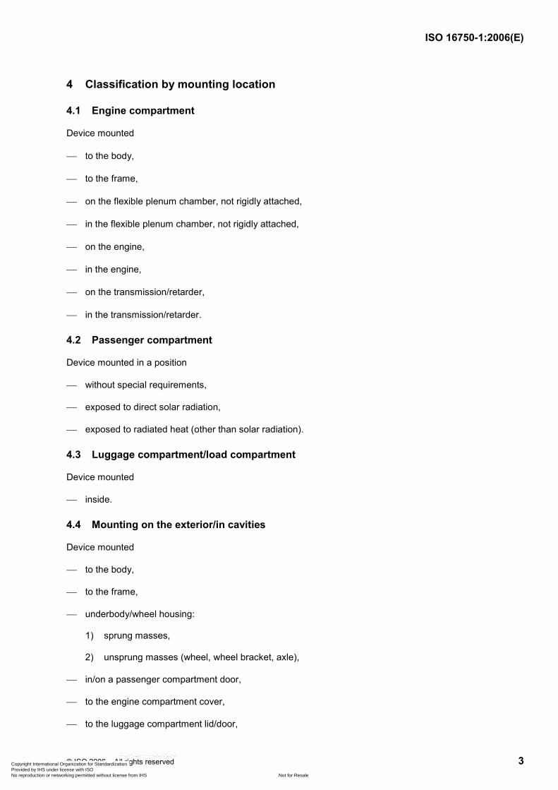
4 Classification by mounting location
4.1 Engine compartment
Device mounted
⎯ to the body,
⎯ to the frame,
⎯ on the flexible plenum chamber, not rigidly attached,
⎯ in the flexible plenum chamber, not rigidly attached,
⎯ on the engine,
⎯ in the engine,
⎯ on the transmission/retarder,
⎯ in the transmission/retarder.
4.2 Passenger compartment
Device mounted in a position
⎯ without special requirements,
⎯ exposed to direct solar radiation,
⎯ exposed to radiated heat (other than solar radiation).
4.3 Luggage compartment/load compartment
Device mounted
⎯ inside.
4.4 Mounting on the exterior/in cavities
Device mounted
⎯ to the body,
⎯ to the frame,
⎯ underbody/wheel housing:
1) sprung masses,
2) unsprung masses (wheel, wheel bracket, axle),
⎯ in/on a passenger compartment door,
⎯ to the engine compartment cover,
⎯ to the luggage compartment lid/door,
Copyright International Organization for Standardization Provided by IHS under license with ISO
Not for ResaleNo reproduction or networking permitted without license from IHS
--`,,```,,,,````-`-`,,`,,`,`,,`---
ISO 16750-1:2006(E)
4 © ISO 2006 – All rights reserved
⎯ to the trunk lid/door,
⎯ to passenger doors on buses,
⎯ in cavities:
1) open towards exterior,
2) open towards interior,
⎯ in special compartments (e.g. battery box).
4.5 Other mounting locations
For some locations with special environmental conditions (e.g. exhaust system), no standard specifications can be given. In these cases, the load shall be stated in the specification of the device.
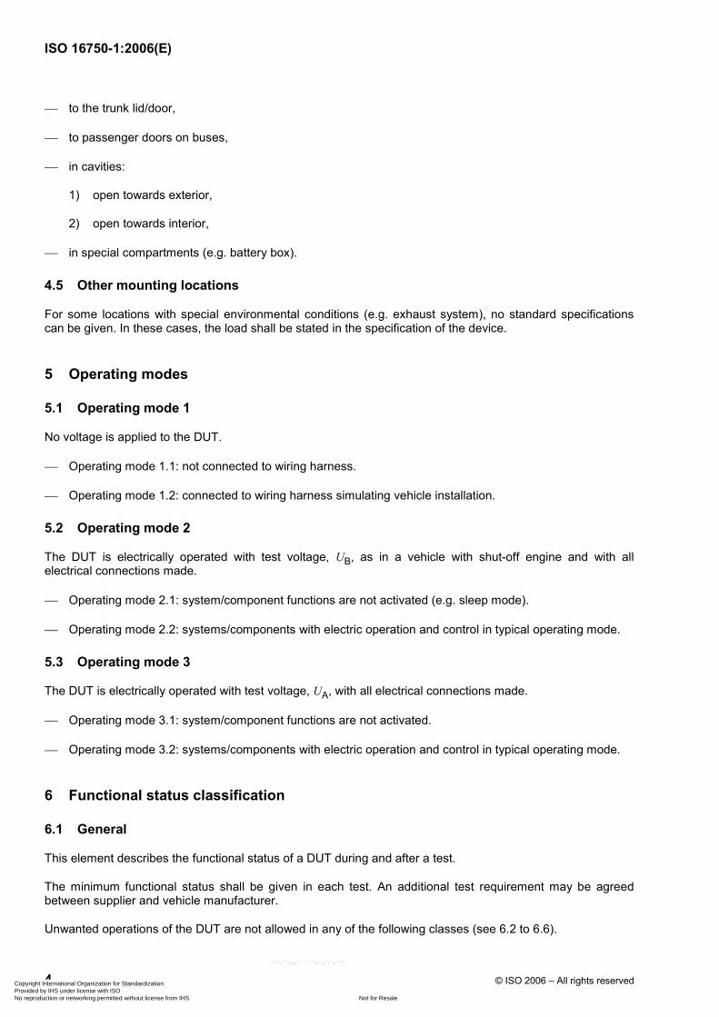
5 Operating modes
5.1 Operating mode 1
No voltage is applied to the DUT.
⎯ Operating mode 1.1: not connected to wiring harness.
⎯ Operating mode 1.2: connected to wiring harness simulating vehicle installation.
5.2 Operating mode 2
The DUT is electrically operated with test voltage, UB, as in a vehicle with shut-off engine and with all electrical connections made.
⎯ Operating mode 2.1: system/component functions are not activated (e.g. sleep mode).
⎯ Operating mode 2.2: systems/components with electric operation and control in typical operating mode.
5.3 Operating mode 3
The DUT is electrically operated with test voltage, UA, with all electrical connections made.
⎯ Operating mode 3.1: system/component functions are not activated.
⎯ Operating mode 3.2: systems/components with electric operation and control in typical operating mode.
6 Functional status classification
6.1 General
This element describes the functional status of a DUT during and after a test.
The minimum functional status shall be given in each test. An additional test requirement may be agreed between supplier and vehicle manufacturer.
Unwanted operations of the DUT are not allowed in any of the following classes (see 6.2 to 6.6).
Copyright International Organization for Standardization Provided by IHS under license with ISO
Not for ResaleNo reproduction or networking permitted without license from IHS
--`,,```,,,,````-`-`,,`,,`,`,,`---
ISO 16750-1:2006(E)
© ISO 2006 – All rights reserved 5
6.2 Class A
All functions of the device/system perform as designed during and after the test.
6.3 Class B
All functions of the device/system perform as designed during the test. However, one or more of them may go beyond the specified tolerance. All functions return automatically to within normal limits after the test. Memory functions shall remain class A.
It shall be specified by the vehicle manufacturer which function of the DUT must perform as designed during the test and which function can be beyond the specified tolerance.
6.4 Class C
One or more functions of a device/system do not perform as designed during the test, but return automatically to normal operation after the test.
6.5 Class D
One or more functions of a device/system do not perform as designed during the test and do not return to normal operation after the test until the device/system is reset by simple “operator/use” action.
6.6 Class E
One or more functions of a device/system do not perform as designed during and after the test and cannot be returned to proper operation without repairing or replacing the device/system.
7 Tests and requirements
7.1 General
The values specified in ISO 16750-2 to ISO 16750-5 will cover basic requirements.
DUTs with several mounting locations shall be tested to meet the most severe requirements.
7.2 General test conditions
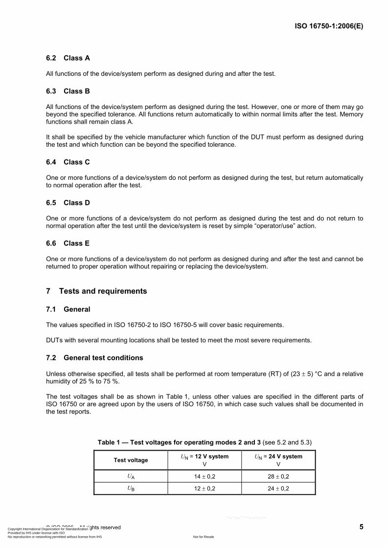
Unless otherwise specified, all tests shall be performed at room temperature (RT) of (23 ± 5) °C and a relative humidity of 25 % to 75 %.
The test voltages shall be as shown in Table 1, unless other values are specified in the different parts of ISO 16750 or are agreed upon by the users of ISO 16750, in which case such values shall be documented in the test reports.
Table 1 — Test voltages for operating modes 2 and 3 (see 5.2 and 5.3)
Test voltage UN = 12 V system V
UN = 24 V system V
UA 14 ± 0,2 28 ± 0,2
UB 12 ± 0,2 24 ± 0,2
Copyright International Organization for Standardization Provided by IHS under license with ISO
Not for ResaleNo reproduction or networking permitted without license from IHS
--`,,```,,,,````-`-`,,`,,`,`,,`---
ISO 16750-1:2006(E)
6 © ISO 2006 – All rights reserved
7.3 Test sequence
Prior to testing, a test sequence plan shall be agreed upon, stating the type, number, combination and sequence of the individual tests.
A life test shall be defined specifically to the product and to be taken into account in the test sequence plan.
An example is given in Annex A.
8 Designation
8.1 Coding
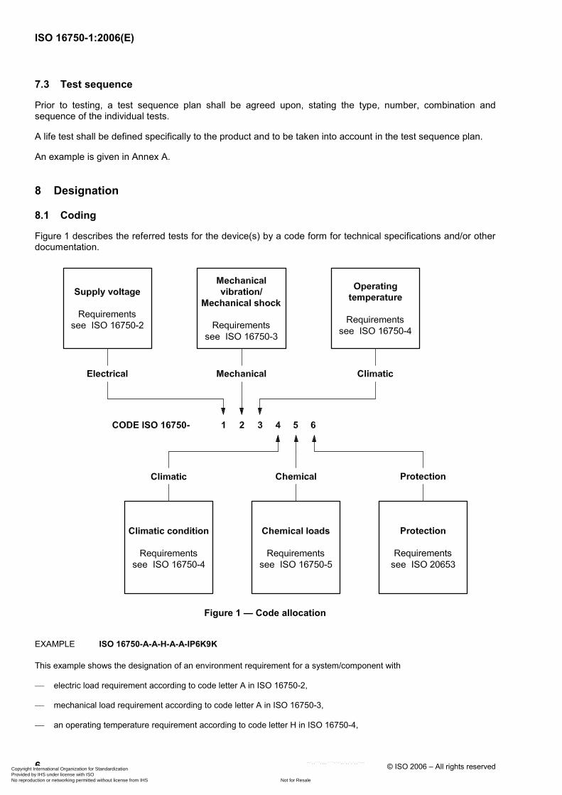
Figure 1 describes the referred tests for the device(s) by a code form for technical specifications and/or other documentation.
Figure 1 — Code allocation
EXAMPLE ISO 16750-A-A-H-A-A-IP6K9K
This example shows the designation of an environment requirement for a system/component with
⎯ electric load requirement according to code letter A in ISO 16750-2,
⎯ mechanical load requirement according to code letter A in ISO 16750-3,
⎯ an operating temperature requirement according to code letter H in ISO 16750-4,
Copyright International Organization for Standardization Provided by IHS under license with ISO
Not for ResaleNo reproduction or networking permitted without license from IHS
--`,,```,,,,````-`-`,,`,,`,`,,`---
ISO 16750-1:2006(E)
© ISO 2006 – All rights reserved 7
⎯ a climatic requirement according to code letter A in ISO 16750-4,
⎯ a chemical load requirement according to code letter A in ISO 16750-5, and
⎯ a degree of protection IP6K9K according to ISO 20653.
8.2 Use of Code Z “as agreed”
ISO 16750 accommodates special needs and situations through the use of Code Z “as agreed”. The use of Code Z should be restricted to cases where the supplier and/or vehicle manufacturer determine that the conditions or tests defined in ISO 16750 are
⎯ not suitable to achieve desired product quality/reliability objectives, and/or
⎯ when the defined conditions or tests are not practical.
When Code Z “as agreed” is used, the following recommendations apply:
⎯ Rationale (reason) for not using the provided conditions or tests shall be documented.
⎯ Complete description of the “as agreed” condition or test should be documented.
⎯ Data and rationale supporting the suitability of the “as agreed” condition or test shall be documented.
⎯ Any specific information regarding Code Z “as agreed” contained in ISO 16750-2 to ISO 16750-5 shall be documented.
⎯ The equipment supplier and vehicle manufacturer shall agree that the “as agreed” documentation is adequate.
Copyright International Organization for Standardization Provided by IHS under license with ISO
Not for ResaleNo reproduction or networking permitted without license from IHS
--`,,```,,,,````-`-`,,`,,`,`,,`---
ISO 16750-1:2006(E)
8 © ISO 2006 – All rights reserved
Annex A (informative)
Example for a test sequence plan
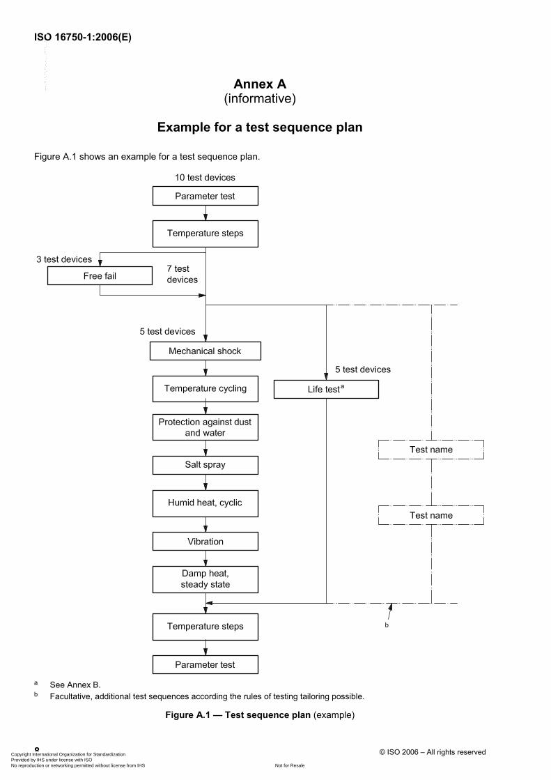
Figure A.1 shows an example for a test sequence plan.
a See Annex B. b Facultative, additional test sequences according the rules of testing tailoring possible.
Figure A.1 — Test sequence plan (example)
Copyright International Organization for Standardization Provided by IHS under license with ISO
Not for ResaleNo reproduction or networking permitted without license from IHS
--`,,```,,,,````-`-`,,`,,`,`,,`---
ISO 16750-1:2006(E)
© ISO 2006 – All rights reserved 9
Annex B (informative)
Example of life test/statement of reliability
B.1 General
In addition to environmental loads, a product used in the vehicle will be subjected to loads induced by its own function, hereafter referred to as functional loads.
These loads are simulated by life tests which generally comprise a combination of functional loads and relevant environmental loads occurring simultaneously.
These tests are performed according to programs derived from in-practice operation.
B.2 Aim of life tests
B.2.1 General
Two fundamentally different cases are to be distinguished, depending on the type of the problem.
B.2.2 Potential design weaknesses
Using real-time life tests or accelerated life tests (with corresponding load increase), the design can be checked for functional loads combined with further environmental loads in order to discover design weaknesses. Generally, only a small number of DUT will suffice to achieve this. This case is by far the more frequent. However, the results are not suitable for deriving a statement on reliability as the number of DUT is too low for a statistically correct statement.
B.2.3 Reliability
Determining reliability is a totally different task. The following step-by-step method is suggested:
a) Determine the type of load which is relevant for service life and specific to the product and determine the test to be conducted.
b) Determine the in-practice load, for example running time, mean temperature, etc.
c) Specify the survival probability and confidence levels and calculate the necessary number of DUT or a test duration on the basis of in-practice load, based on statistical correlation. Generally, this calculation requires extensive testing.
d) A reduction of this extensive testing resulting from step c) to feasible values can be performed by a permissible increase of load on the basis of an appropriate correlation between in-practice experience and testing. The increase in load shall not lead to a change of the expected damage process. Generally, compared to the check of potential design weaknesses, considerably more extensive testing will be required.
It is recommended to employ the step-by-step method also in the first case for checking design; however, step c) is omitted (statistics calculation).
Copyright International Organization for Standardization Provided by IHS under license with ISO
Not for ResaleNo reproduction or networking permitted without license from IHS
--`,,```,,,,````-`-`,,`,,`,`,,`---
ISO 16750-1:2006(E)
10 © ISO 2006 – All rights reserved
B.3 Calculation of characteristic reliability values on the basis of test data
B.3.1 General statistical correlation
If characteristic reliability values are required, e.g. stating the survival probability, R(t), for the period of time, t, and with a necessarily specified confidence level, PA, these can be evaluated by the statistical calculation described in the following Equation B.1, using life test data.
The calculation is based on the following correlation: Correlating the Weibull distribution with the binomial distribution yields the following equation:
( ) ( )1
A1T
n tR t Pβ⎛ ⎞⋅ ⎜ ⎟
⎝ ⎠−W (B.1)
where
R(t) is the survival probability as a function of time (or cycles/operations);
PA is the confidence level (assumption);
β is the Weibull form factor;
n is the number of DUT;
t is the test duration (time or cycles or operations);
T is the specified service life (time or cycles or operations).
When applying this correlation, two conditions shall be met.
⎯ There shall be no failures during testing; if failures occur, only the test duration up to the first failure shall be used for the calculation.
⎯ Failures expected in practice shall have Weibull distribution.
Depending on the task, the equation described above shall be solved to give the required quantity, other quantities must be known. If this is not the case, these quantities shall be determined by experiment or by using figures based on experience.
In B.3.2, the method will be explained by using an example.
B.3.2 Example for the determination of the test duration required for a given reliability
B.3.2.1 DUT
A plastic coated coil without moving parts used in the passenger car engine compartment has been chosen for this example.
Specifications are the following:
⎯ service life 10 years;
⎯ survival probability R = 0,99 (failure rate 1 %);
⎯ confidence level PA = 0,9 (normal value).
Copyright International Organization for Standardization Provided by IHS under license with ISO
Not for ResaleNo reproduction or networking permitted without license from IHS
--`,,```,,,,````-`-`,,`,,`,`,,`---
ISO 16750-1:2006(E)
© ISO 2006 – All rights reserved 11
B.3.2.2 Determination of the load which is specific to the product and relevant for service life
According to experiences made with these and similar products, the main load can be determined as the load resulting from mechanical stresses due to various thermal expansion processes of the various components which are caused by temperature cycle stresses.
This leads to the temperature cycle test as the test to be applied.
B.3.2.3 Determination of the in-practice load
The highest temperature rise occurring in practice is the temperature rise resulting from heating the engine compartment starting from the cold operating condition. Due to the high thermal load of the vehicle, this temperature rise can only occur for a maximum of twice a day; for 10 years this results in 7 300 temperature cycles with a temperature rise of (determined by measurement) ∆T = 70 K.
The numerous small rises in temperature are disregarded for this approximation. Why this is permissible will be shown in B.3.2.5.
B.3.2.4 Calculation of the test duration
The test duration results from the required number of temperature cycles in the test.
Using:
1 testv
prac
NL
N= and Equation B.1
yields:
1
A1 test prac
1ln(1 )
ln
PnN N
R
β⎛ ⎞− ⋅⎜ ⎟= ⎜ ⎟
⎜ ⎟⎜ ⎟⎝ ⎠
where
N1 test is the required number of temperature cycles in the test with in-practice temperature rise;
Nprac is the number of temperature cycles occurring in practice: 7 300 (in 10 years);
R is the survival probability: 0,99 (specification);
PA is the confidence level (assumption): 0,9;
β is the Weibull form factor: 3 (determined in experiment, for wire fracture);
n is the number of DUT: 45 (small and simple DUT).
With the values above inserted, the result is N1 test = 12 558, i.e. for an in-practice load of ∆T = 70 K, 12 558 test cycles are necessary to ensure the specified reliability of R = 0,99 (additional condition: no failure).
As such a test duration is not tolerable, a reduction can be achieved by a permissible increase of load (see B.3.2.5).
Copyright International Organization for Standardization Provided by IHS under license with ISO
Not for ResaleNo reproduction or networking permitted without license from IHS
--`,,```,,,,````-`-`,,`,,`,`,,`---
ISO 16750-1:2006(E)
12 © ISO 2006 – All rights reserved
B.3.2.5 Load increase
A calculation method suitable for increased load is the Coffin Manson formula. For the case considered here, the formula is as follows:
∆∆
prac1 test2 test
test
kTN N T
⎡ ⎤⎢ ⎥⋅⎢ ⎥⎣ ⎦
=
where
N2 test is the number of test cycles with test temperature rise;
N1 test is the number of test cycles with in-practice temperature rise;
∆Tprac is the in-practice temperature rise: 70 K;
∆Ttest is the test temperature rise: 160 K (−40 °C to 120 °C), these are the maximum tolerable temperatures;
k is the exponent depending on the failure process: 5 (determined in experiment, S/N (stress versus number of cycles) gradient).
With the values above, the result is N2 test = 200 cycles, because k = 5 is a high exponent, small temperature rises can be disregarded.
B.3.3 Conclusions
The determination of reliability by life tests is governed by the following factors (the required service life with the corresponding minimum reliability is usually given).
⎯ “Failure behaviour” (Weibull form factor) has a major impact on the result: a higher failure gradient yields shorter test duration.
⎯ Especially with low failure gradients, the “number of DUT” has a high impact.
⎯ “Confidence level”, excessive requirements for the confidence level result in longer test duration and higher numbers of DUT.
The method described can be used successfully if there is distinct failure behaviour due to wear or fatigue and if a high increase in load is permissible for testing. This is often applicable to mechanical and electro-mechanical products.
Unfortunately, this method can generally not be used for purely electronic components, because the more accidental failure behaviour (Weibull form factor approximately 1) leads to intolerably extensive testing (number of DUT and test duration) and an increase in load (e.g. temperature rise) is only possible to a moderate extent.
Copyright International Organization for Standardization Provided by IHS under license with ISO
Not for ResaleNo reproduction or networking permitted without license from IHS
--`,,```,,,,````-`-`,,`,,`,`,,`---

Copyright International Organization for Standardization Provided by IHS under license with ISO
Not for ResaleNo reproduction or networking permitted without license from IHS
--`,,```,,,,````-`-`,,`,,`,`,,`---
ISO 16750-1:2006(E)
ICS 43.040.10 Price based on 12 pages
© ISO 2006 – All rights reserved
Copyright International Organization for Standardization Provided by IHS under license with ISO
Not for ResaleNo reproduction or networking permitted without license from IHS
--`,,```,,,,````-`-`,,`,,`,`,,`---