Residual Stress Analysis of Q1N Submarine Pressure...
76
Defence R&D Canada – Atlantic DEFENCE DÉFENSE & Residual Stress Analysis of Q1N Submarine Pressure Hull Steel with the Portable Miniature X-Ray Diffractometer Shannon Farrell Luke MacGregor Technical Memorandum DRDC Atlantic TM 2007-335 May 2008 Copy No. _____ Defence Research and Development Canada Recherche et développement pour la défense Canada
Transcript of Residual Stress Analysis of Q1N Submarine Pressure...
Defence R&D Canada – Atlantic
DEFENCE DÉFENSE&
Residual Stress Analysis of Q1N
Submarine Pressure Hull Steel with the
Portable Miniature X-Ray Diffractometer
Shannon Farrell
Luke MacGregor
Technical Memorandum
DRDC Atlantic TM 2007-335
May 2008
Copy No. _____
Defence Research andDevelopment Canada
Recherche et développementpour la défense Canada

This page intentionally left blank.
Residual Stress Analysis of Q1N Submarine Pressure Hull Steel with the Portable Miniature X-Ray Diffractometer
Shannon Farrell and Luke MacGregor
Defence R&D Canada – Atlantic
Technical Memorandum
DRDC Atlantic TM 2007-335
May 2008
Principal Author
Dr. Shannon P. Farrell
Approved by
Dr. Calvin V. Hyatt
Section Head / Dockyard Laboratory (Atlantic)
Approved for release by
Dr. James L. Kennedy
Chair / Document Review Panel
© Her Majesty the Queen in Right of Canada, as represented by the Minister of National Defence, 2008
© Sa Majesté la Reine (en droit du Canada), telle que représentée par le ministre de la Défense nationale, 2008
Original signed by Dr. Shannon P. Farrell
Original signed by Jeffery P. Szabo for
Original signed by Dr. James L. Kennedy
DRDC Atlantic TM 2007-335 i
Abstract ……..
Accurate depiction of residual stress state in submarine structures using X-ray diffraction requires microstructural/compositional analysis and reliable equipment and methodology for analysis. This study was conducted to assess the portable miniature X-ray diffractometer (MXRD), owned and operated by Defence R&D Canada, for accurate determination of residual stress on tempered Q1N steels such as found on the pressure hull of VICTORIA Class submarines. In the absence of microstructural effects and instrumental alignment issues, not identified in this study, the accuracy of residual stress analysis is believed to be dependent on the accuracy of techniques used for derivation of the X-ray elastic constant (XREC) required for residual stress analysis. In this report, effective XRECs were determined using several methods (literature references, experimental measurement of tensile properties and four-point bending experiments) and results were compared. Specimens of tempered Q1N steel were extracted from the pressure hull of HMCS VICTORIA. A modulus of elasticity of 213 GPa in bending and 208 GPa in tension were determined for the tempered Q1N steel, consistent with literature values for similar steel. Effective XRECs from the MXRD supplier and open literature (specific to the {211} crystallographic planes of bcc Fe) were found to be similar to values derived from tension (163.5 GPa) and four-point bending (167 GPa) tests.
Although effective XRECs provide a reasonable estimate, the sensitivity of the XREC to composition and microstructure requires a more accurate value determined from experiment. The experimental XREC was calculated as 195 ±6 GPa (for the {211} crystallographic planes of bcc Fe) for the Q1N steel using the multiple angle method. This value was similar to the XREC derived using the double angle method (200 ±7 GPa). Although similar results were found from both methods, this may not be necessarily true for other materials where compositional and microstructural features (grain interactions, texture, etc.) are more pronounced. Therefore, the multiple angle technique is the preferred method due to the improved statistics and its sensitivity to microstructural effects. The importance of understanding the instrumental errors and operator bias on the accuracy of MXRD residual stress analysis is also discussed. A procedure for calibration of the MXRD for future residual stress investigations on Q1N steel (relevant to other materials) has been proposed.
Résumé ….....
Pour pouvoir faire une description précise de l état de contrainte résiduelle dans les structures d un sous-marin au moyen de la diffraction X, il faut faire une analyse de la microstructure/composition, avoir de l équipement fiable et une bonne méthode d analyse. La présente étude a été réalisée afin d évaluer la capacité du diffractomètre à rayons X miniature portatif (MXRD), propriété de RDDC et exploité par RDDC, à déterminer avec précision la contrainte résiduelle d aciers revenus Q1N, comme ceux se retrouvant dans la coque de haute pression des sous-marins de la classe VICTORIA. En l absence de problèmes d effets micro-structurels et d alignement des appareils, que nous n avons pas rencontrés lors de la présente étude, on pense que la précision de l analyse de la contrainte résiduelle dépend de la précision des techniques utilisées pour le calcul de la constante élastique sous rayons X (XREC) requise pour
ii DRDC Atlantic TM 2007-335
cette analyse. Dans le présent rapport, on a déterminé des XREC efficaces au moyen de plusieurs méthodes (références bibliographiques, mesures expérimentales des propriétés d allongement et expériences de déformation en quatre points), et les résultats ont été comparés. Des éprouvettes d acier revenu Q1N ont été extraites de la coque de haute pression du NCSM VICTORIA. On a déterminé un module élastique de 213 GPa en déformation et de 208 GPa en tension pour l acier revenu Q1N, valeurs correspondant à celles de la littérature pour des aciers similaires. On a trouvé que les XREC efficaces du fournisseur du MXRD et de la littérature (spécifiques au plans cristallographiques {211} du Fe cubique centré) étaient similaires aux valeurs calculées à partir des tests en tension (163,5 GPa) ou de déformation en quatre points (167 GPa).
Bien que les XREC efficaces fournissent une estimation raisonnable, la sensibilité de la XREC à la composition et à la microstructure exige la détermination expérimentale d une valeur plus précise. On a calculé que la XREC expérimentale était de 195 ±6 GPa (pour les plans cristallographiques {211} du Fe cubique centré) pour l acier Q1N, au moyen de la méthode à angle multiple. Cette valeur est similaire à celle calculée au moyen de la méthode à angle double (200 ±7 GPa). Bien que des résultats similaires aient été trouvés par les deux méthodes, ceci n est pas nécessairement vrai pour d autres matériaux dans lesquels les caractéristiques de composition et de microstructure (interactions des grains, texture, etc.) sont plus prononcées. La technique à angle multiple est donc la méthode préférée en raison de meilleurs résultats statistiques et de sa plus grande sensibilité aux effets microstructuraux. On discute également de l importance de la compréhension des erreurs expérimentales et de l erreur systématique due à l opérateur sur la précision de l analyse des contraintes résiduelles au moyen du MXRD. On propose une procédure d étalonnage du MXRD pour de futures études de la contrainte résiduelle dans l acier Q1N (pertinente pour d autres matériaux).
DRDC Atlantic TM 2007-335 iii
Executive summary
Residual Stress Analysis of Q1N Submarine Pressure Hull Steel with the Portable Miniature X-Ray Diffractometer:
Shannon Farrell; Luke MacGregor; DRDC Atlantic TM 2007-335; Defence R&D Canada – Atlantic; May 2008.
Introduction: This work follows on a previous investigation that marked the inaugural measurement of residual stress in-situ on a submarine pressure hull made of Q1N steel in Canada. During that investigation, the portable miniature X-ray diffractometer (MXRD) was employed to assess the state of residual stress in the pressure hull of HMCS VICTORIA before insertion and welding of a new insert plate. As a consequence, questions had arisen concerning the accuracy of X-ray diffraction (XRD) techniques for determination of residual stress on Q1N steels. This document is intended to answer some of these concerns and to determine a procedure for calibration of the MXRD for future residual stress investigations on tempered Q1N steel.
Results: In the absence of microstructural effects and instrumental alignment issues, not identified in this study, the accuracy of residual stress analysis is believed to be dependent on the derivation of the X-ray elastic constant (XREC) required for residual stress analysis. In this report, effective XRECs were determined with several methods (literature references, experimental measurement of tensile properties and four-point bending experiments) and results were compared. A procedure for calibration of the MXRD for residual stress investigations on tempered Q1N steel (and relevant to other materials) has been proposed. The experimental XREC was calculated to be 195 ±6 GPa (for the {211} crystallographic planes of bcc Fe) for the Q1N steel using the multiple angle method. This value will be used for future residual stress investigations on Q1N pressure hull steel.
Significance: Accurate depiction of residual stress state in submarine structures using X-ray diffraction requires microstructural/compositional analysis and reliable equipment and methodology for analysis. Residual stress analysis is of great significance to the Canadian Navy. Residual stress analysis is often employed to validate repair procedures and for condition-based monitoring. It is often a significant component of failure analysis, extension of service life of components and structures and, for enhancement of effectiveness of models to predict these phenomena. This study is part of a larger initiative aimed at employing in-situ XRD techniques for conduction of residual stress analysis on structural components. In particular, understanding the redistribution of residual stress during pressure hull repair/modification procedures on the VICTORIA Class submarines is a foremost concern as this affects pressure hull integrity and impacts the performance and safe operational limits.
Future plans: A follow-up investigation will look at the effects of thermal stress, thermal history and composition on the microstructure and residual stress in Q1N steels to provide insight into the residual stress distribution in welds. A comprehensive investigation of residual stress on the pressure hull of HMCS VICTORIA has been completed in the area where the new pressure hull insert plate was fit-up and welded; a report is forthcoming. This will be beneficial in assessing the implication of the insert plate welding procedure and provide valuable insight for future weld repair procedures.
iv DRDC Atlantic TM 2007-335
Sommaire .....
Analyse de la contrainte résiduelle de l’acier Q1N à coque de haute pression d’un sous-marin au moyen du diffractomètre à rayons X miniature et portatif
Shannon Farrell; Luke MacGregor; DRDC Atlantic TM 2007-335; R & D pour la défense Canada – Atlantique; Mai 2008.
Introduction : le présent travail fait suite à une étude au cours de laquelle la première mesure in situ de la contrainte résiduelle dans l acier Q1N à coque de haute pression d un sous-marin avait réalisée au Canada. Lors de cette étude, on avait utilisé le diffractomètre à rayons X miniature portatif (MXRD) pour évaluer l état de contrainte résiduelle dans la coque de haute pression du NCSM VICTORIA avant insertion et soudage d une nouvelle plaque. Suite à cette étude, des questions sur la précision des techniques de diffraction X (XRD) pour la détermination de la contrainte résiduelle dans des aciers Q1N se sont posées. Dans le présent document, on entend répondre à certaines de ces questions et élaborer une procédure pour étalonner le MXRD qui servira lors de futures études sur la contrainte résiduelle dans l acier revenu Q1N.
Résultats : en l absence de problèmes d effets micro-structurels et d alignement des appareils, que nous n avons pas rencontrés lors de la présente étude, on pense que la précision de l analyse de la contrainte résiduelle dépend de la précision des techniques utilisées pour le calcul de la constante élastique sous rayons X (XREC) requise pour cette analyse. Dans le présent rapport, on a déterminé des XREC efficaces au moyen de plusieurs méthodes (références bibliographiques, mesures expérimentales des propriétés d allongement et expériences de déformation en quatre points), et les résultats ont été comparés. On y propose une procédure pour l étalonnage du MXRD pour des études sur la contrainte résiduelle de l acier revenu Q1N (et d autres matériaux). On a calculé que la XREC expérimentale était de 195 ±6 GPa (pour les plans cristallographiques {211} du Fe cubique centré) pour l acier Q1N, au moyen de la méthode à angle multiple. Cette valeur sera utilisée lors de futures études sur la contrainte résiduelle de l acier Q1N pour coque de haute pression.
Importance : pour pouvoir faire une description précise de l état de contrainte résiduelle dans les structures d un sous-marin au moyen de la diffraction X, il faut faire une analyse de la microstructure/composition, avoir de l équipement fiable et une bonne méthode d analyse. L analyse de la contrainte résiduelle est d une grande importance pour la Marine canadienne. L analyse de la contrainte résiduelle est souvent utilisée pour valider des procédures de réparation et pour la surveillance en fonction de la condition. C est souvent un élément important de l analyse de défaillance, du prolongement de la vie d éléments et de structures et pour l amélioration de l efficacité de modèles de prédiction de ces phénomènes. La présente étude fait partie d une initiative plus large ayant pour objectif l utilisation in situ de techniques XRD pour la réalisation d une analyse de contrainte résiduelle sur des éléments structurels. En particulier, la compréhension de la redistribution de la contrainte résiduelle lors de procédures de réparation/modification de la coque de haute pression de sous-marins de la classe VICTORIA est d importance capitale, car elle affecte l intégrité de la coque et a un impact sur les limites de performance et d exploitation sécuritaire.
DRDC Atlantic TM 2007-335 v
Perspectives : au cours de travaux futurs, on étudiera les effets de la contrainte thermique, de l historique thermique et de la composition sur la microstructure et la contrainte résiduelle d aciers Q1N afin de comprendre la distribution de la contrainte résiduelle dans les soudures. Une étude exhaustive de la contrainte résiduelle dans la coque du NCSM VICTORIA a été complétée dans la zone où une nouvelle plaque a été insérée et soudée. Un rapport sur ce sujet sera prochainement publié. Ceci nous aidera à évaluer les conséquences de la procédure de soudage de la plaque insérée et nous fournira des renseignements précieux pour de futures procédures de réparation par soudage.

vi DRDC Atlantic TM 2007-335
This page intentionally left blank.
DRDC Atlantic TM 2007-335 vii
Table of contents
Abstract .. ................................................................................................................................. i
Résumé ..... ................................................................................................................................... i
Executive summary ....................................................................................................................... iii
Sommaire ....................................................................................................................................... iv
Table of contents ........................................................................................................................... vii
List of figures ................................................................................................................................. ix
List of tables .................................................................................................................................... x
Acknowledgements ........................................................................................................................ xi
1....Introduction............................................................................................................................... 1
2....Background Information........................................................................................................... 3 2.1 Residual Stress Analysis................................................................................................ 3
2.1.1 Importance ...................................................................................................... 3 2.1.2 Techniques Available for Measurement ......................................................... 3
2.2 Basics of X-Ray Diffraction .......................................................................................... 4 2.2.1 Diffraction of X-Rays ..................................................................................... 4 2.2.2 X-Ray Diffraction Residual Stress Analysis................................................... 6
2.2.2.1 Residual Strain.............................................................................. 6 2.2.2.2 Residual Stress.............................................................................. 6
2.3 The Miniature X-Ray Diffractometer............................................................................ 8 2.3.1 Measurement of Strain .................................................................................... 9 2.3.2 Sensitivity and Reproducibility..................................................................... 10
2.4 Specimen Considerations ............................................................................................ 10 2.4.1 Phases............................................................................................................ 11 2.4.2 Grain size and Texture .................................................................................. 13 2.4.3 Cold Work..................................................................................................... 13
2.5 The X-Ray Elastic Constant ........................................................................................ 13 2.5.1 The Experimental X-Ray Elastic Constant ................................................... 14 2.5.2 The Effective X-Ray Elastic Constant .......................................................... 14
3....Experimental Methods............................................................................................................ 19 3.1 Preparation of Tempered Q1N Steel Specimens ......................................................... 19
3.1.1 Tensile Specimens......................................................................................... 19 3.1.2 Four-Point Bend Specimens.......................................................................... 20
3.2 Four-Point Bending Tests............................................................................................ 20 3.2.1 Strain Measurement ...................................................................................... 21 3.2.2 Specimen Pre-Loading .................................................................................. 22 3.2.3 Four-Point Bending Experiments.................................................................. 22 3.2.4 Applied Load................................................................................................. 22
viii DRDC Atlantic TM 2007-335
3.3 MXRD Measurements................................................................................................. 23 3.3.1 Operational Parameters ................................................................................. 23 3.3.2 Calibration of the MXRD.............................................................................. 24
4....Determination of X-Ray Elastic Constants............................................................................. 26 4.1 The Effective XREC.................................................................................................... 26
4.1.1 Tensile Testing of Q1N Steel ........................................................................ 27 4.1.2 The Modulus of Elasticity in Bending .......................................................... 28 4.1.3 Effective XREC of Q1N Steel ...................................................................... 30
4.2 The Experimental XREC............................................................................................. 31 4.2.1 Four-Point Bending Experiments.................................................................. 32 4.2.2 Calculation of the Experimental XREC........................................................ 35
4.2.2.1 Multiple Angle Method .......................................................... 35 4.2.2.2 The Double Angle Method..................................................... 37
4.2.3 Experimental XREC of Q1N Steel ............................................................... 38 4.3 Discussion ................................................................................................................... 38
4.3.1 Reliability of Results..................................................................................... 38 4.3.2 Determination of the XREC.......................................................................... 40 4.3.3 Procedure for Future Residual Stress Analysis ............................................. 42
5....Conclusions............................................................................................................................. 43
6....Future Work............................................................................................................................ 45
References ..... ............................................................................................................................... 46
Annex A .. Comparison of Residual Stress Measurment Techniques ........................................... 49
List of symbols/abbreviations/acronyms/initialisms .................................................................... 51
Distribution list ............................................................................................................................. 53
DRDC Atlantic TM 2007-335 ix
List of figures
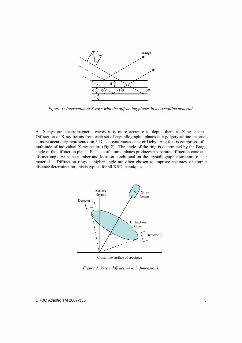
Figure 1: Interaction of X-rays with the diffracting planes in a crystalline material....................... 5
Figure 2: X-ray diffraction in 3 dimensions. ................................................................................... 5
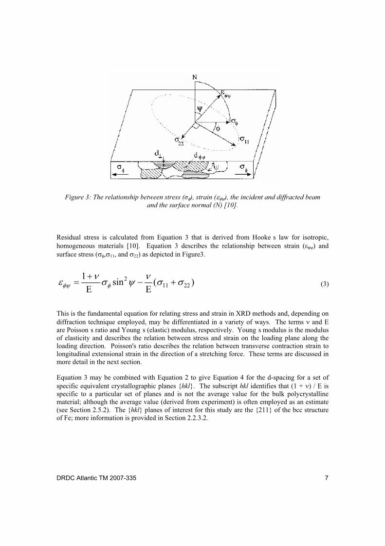
Figure 3: The relationship between stress ( ), strain ( ), the incident and diffracted beam and the surface normal (N) [10]. ................................................................................... 7
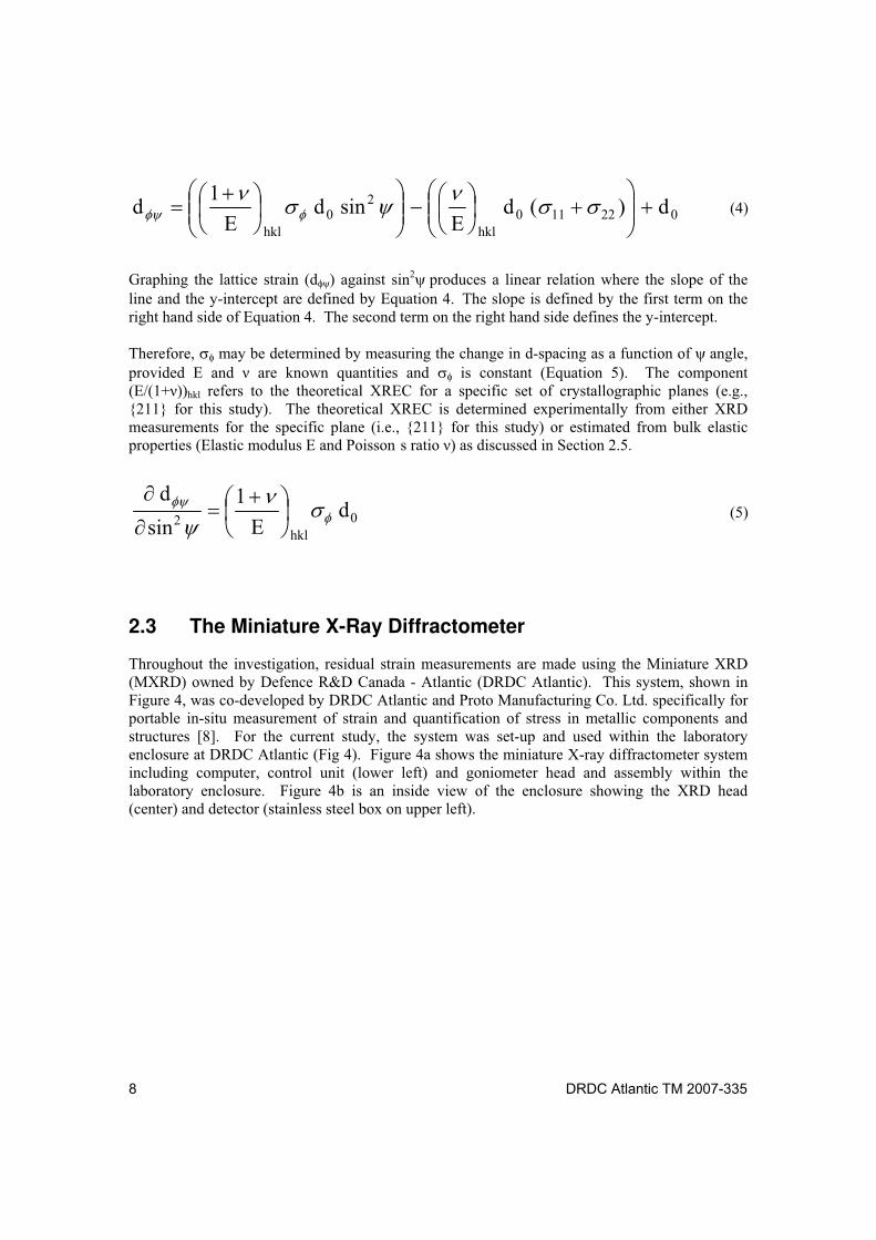
Figure 4: The miniature X-ray diffractometer system (a) including computer, control unit, and goniometer head and assembly within the laboratory enclosure and (b) view inside the enclosure showing the XRD head (center) and detector (upper left). ..................... 9
Figure 5: Tensile specimen with gauges (a) before and (b) after tensile testing. .......................... 19
Figure 6: (a) Top view and (b) bottom view of four-point bend specimen with gauges. .............. 20
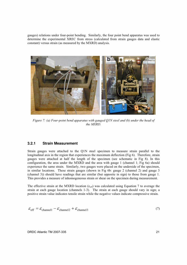
Figure 7: (a) Four-point bend apparatus with gauged Q1N steel and (b) under the head of the MXRD......................................................................................................................... 21
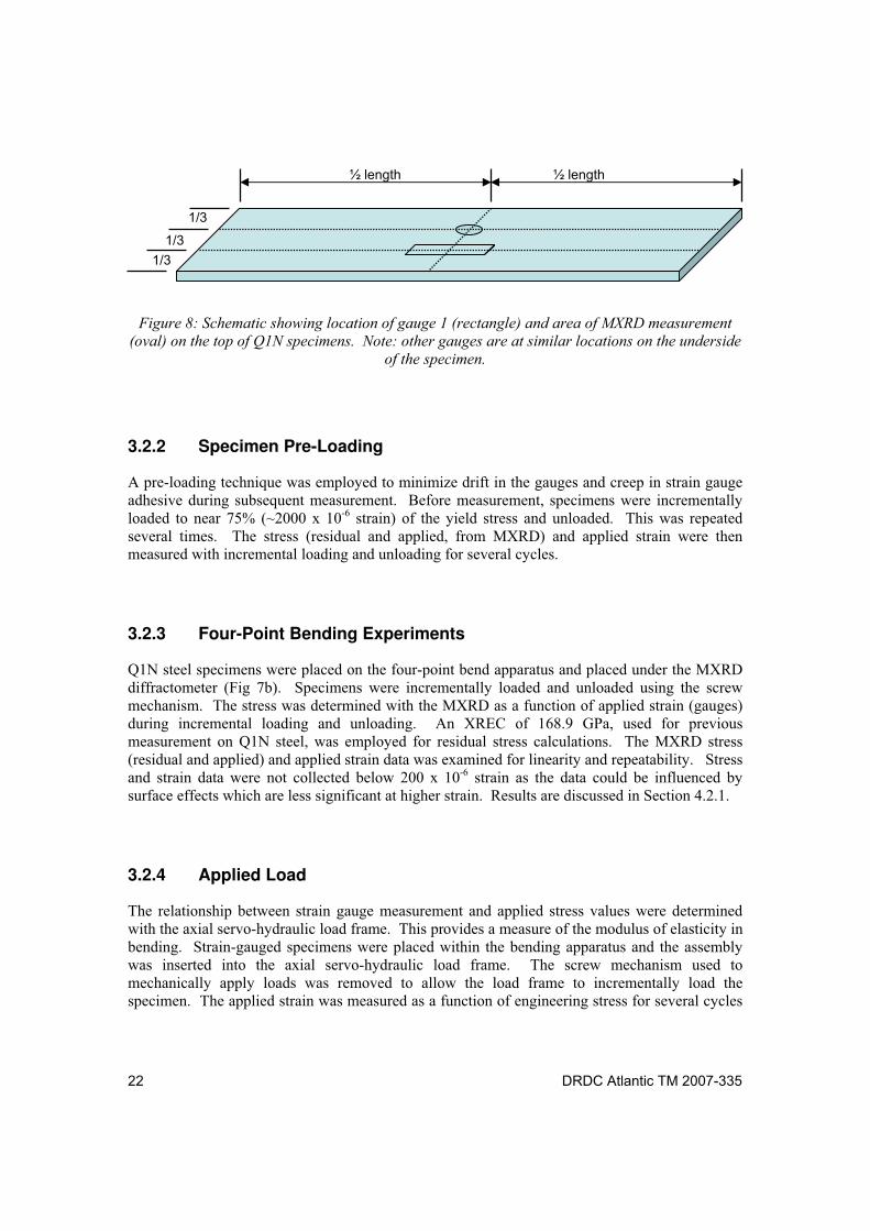
Figure 8: Schematic showing location of gauge 1 (rectangle) and area of MXRD measurement (oval) on the top of Q1N specimens. Note: other gauges are at similar locations on the underside of the specimen..................................................... 22
Figure 9: Stress-strain curve for Q1N steel (blue). Young s elastic modulus was determined from a portion of the slope (shown in black, from 100 to 300 MPa) of the linear elastic region. .............................................................................................................. 27
Figure 10: Average strain (longitudinal and transverse) as a function of engineering stress for Q1N steel. Poisson s ratio was determined from the ratio between the slopes of the best fit lines. .......................................................................................................... 28
Figure 11: Engineering stress versus strain relationship during four-point bending of Q1N steel during loading (blue) and unloading (red). The modulus of elasticity in bending was determined from the slope of the best fit line during unloading (red). Strain was determined using the results of 3 strain gauges as per Equation 7. ........... 30
Figure 12: Change in MXRD measured stress as a function of applied strain during loading and unloading under four-point bending (XREC=168.9 GPa).................................... 33
Figure 13: Change in lattice spacing as a function of angle ( d sin2 relative to applied stress for Q1N steel using the multiple angle method. ............................................ 36
Figure 14: Change in lattice spacing relative to applied stress for Q1N steel using the double angle method. .......................................................................................................... 37
x DRDC Atlantic TM 2007-335
List of tables
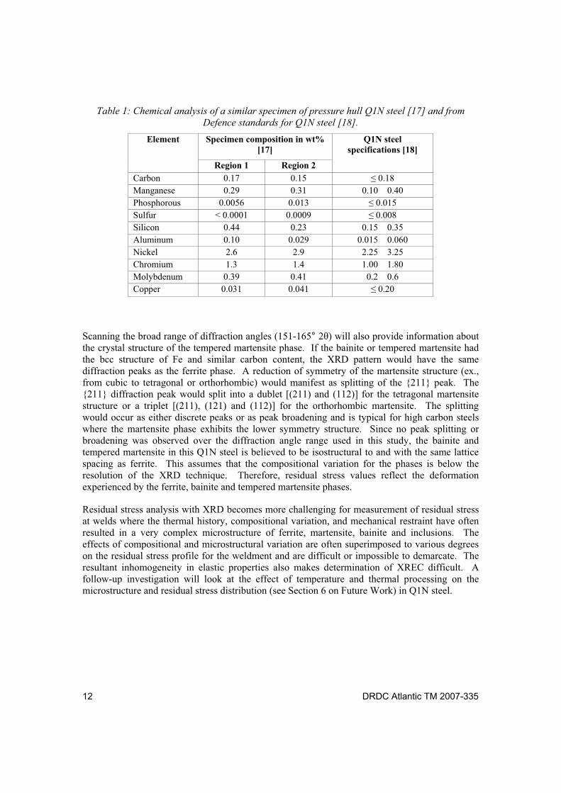
Table 1: Chemical analysis of a similar specimen of pressure hull Q1N steel [17] and from Defence standards for Q1N steel [18]. ........................................................................ 12
Table 2: Effective XRECs for steel as derived from different methods........................................ 16
Table 3: Variation of the XREC and Poisson s ratio ( ) with thermomechanical treatment of HSLA-100 steel [26]. .................................................................................................. 17
Table 4: MXRD residual strain measurement parameters............................................................. 23
Table 5: MXRD residual stress analysis parameters. .................................................................... 23
Table 6: Calibration results to verify the alignment of the MXRD. .............................................. 24
Table 7: Effective XRECs for Q1N steel as derived from different methods. .............................. 31
Table 8: Microstrain measurements and applied load for Q1N steel (specimen 2) under four-point bending............................................................................................................... 32
Table 9: Applied load and MXRD stress-strain data for Q1N steel (specimen 2) under four-point bending............................................................................................................... 34
Table 10: Results for XRECs determined using the double and multiple angle methods............. 36
Table 11: Comparison of XRECs relevant to this study................................................................ 40
Table A-1: Comparison of destructive techniques for measurement of residual stress [2]. .......... 49
Table A-2: Comparison of non-destructive techniques for measurement of residual stress [2].... 50
DRDC Atlantic TM 2007-335 xi
Acknowledgements
The authors would like to thank Mr. Robert Drake and Mr. Mohammed Belassel of Proto Manufacturing Co. Ltd for their assistance with residual stress theory and measurements. They also thank Dr. Allison Nolting of the Dockyard Laboratory (Atlantic) of DRDC Atlantic for assistance with tensile tests.

xii DRDC Atlantic TM 2007-335
This page intentionally left blank.
DRDC Atlantic TM 2007-335 1
1 Introduction
Residual stress analysis of submarine pressure hull steel is an integral part of Defence R&D Canada s (DRDC) commitment to scientific support to the VICTORIA Class submarines. The recent introduction of the VICTORIA Class submarines into service marks the onset of a new era of Canadian naval capabilities. This also introduces significant unique materials related challenges not seen since the OBERON Class submarines were in use. In particular, pressure hull repair/modification procedures are a foremost concern as they affect pressure hull integrity and impact the performance and safe operational limits of the submarines. Residual stress analysis is often employed to validate repair procedures and for condition-based monitoring. It is often a significant component of failure analysis, extension of service life of components and structures and, for enhancement of effectiveness of models to predict these phenomena.
This study is part of a larger research initiative aimed at employing in-situ X-ray diffraction (XRD) for conduction of residual stress analysis on submarine structural components and for assessment of repair/modification procedures. This work follows on a previous investigation that marked the inaugural measurement of residual stress in-situ on a submarine pressure hull made of Q1N (Q1 Navy Steel) in Canada. During that initial investigation, baseline residual stress values were evaluated on the pressure hull of HMCS VICTORIA during a repair procedure [1]. This provided insight into the level of residual stress and on the spatial variation of these measurements to structural components (welds, frames, etc) on the interior and exterior of the pressure hull before insertion and welding of the new pressure hull plate. The accuracy and precision of the XRD method for residual stress analysis was reported in terms of literature estimates and round-robin style studies [1]. This provided an overview of instrumental and experimental errors that are often encountered during XRD-based residual stress measurement on Q1N steel.
During the course of the previous study, questions had arisen concerning the accuracy of the portable miniature X-ray diffractometer (MXRD) for residual stress analysis on Q1N pressure hull steels. These concerns will be addressed in this study and are considered in terms of the XRD instrument employed and the microstructure and elastic properties of the material investigated. With respect to the instrument, the XRD technique will be compared to other commonly used residual stress analysis techniques and the fundamentals of residual stress analysis with XRD will be explained. In particular, the significance of the X-ray elastic constant (XREC) for representing the elastic properties of the microstructure of the Q1N steel in residual stress calculations is examined. This constant is essential for calculating stress from strain values measured by the XRD and is experimentally-derived or estimated (effective XREC) from similar studies.
In this work, effective XRECs for Q1N steel will be derived from literature references or approximated from experimental measurement of mechanical properties. The experimental XREC for tempered Q1N steel was determined from MXRD measurements during four-point bend testing. This method is believed to more accurately represent the relationship between stress and strain determined with XRD techniques. In particular, the experimental XREC was determined from the relationship of MXRD measured strain or change in lattice spacing, and applied stress under four-point bending using two comparable techniques. Each technique was
2 DRDC Atlantic TM 2007-335
compared and evaluated with a suitable method for accurate derivation of the XREC as an endpoint.
This document is intended to assess the accuracy of the portable MXRD and to establish a standard procedure for calibration of the MXRD for residual stress investigations on tempered Q1N steel. The document is organized as follows. In Section 2, background information, XRD theory, design of the MXRD and effects of the microstructure of steel are considered in relation to residual stress analysis. Experimental methods are discussed in Section 3. In Section 4, methods for determination of the XREC for Q1N steel are presented and discussed. Conclusions and future work plan are provided in Section 5 and 6, respectively. A comparison of residual stress measurement techniques is described in Annex A.
DRDC Atlantic TM 2007-335 3
2 Background Information
2.1 Residual Stress Analysis
2.1.1 Importance
Residual stresses are stresses that, though caused by external stimuli, persist within a material after external stimuli have been removed. The magnitude of residual stresses has a profound effect on mechanical behaviour (ex., distortion, fatigue, fracture, corrosion, etc.) of materials and the performance of the component. These stresses may act in a positive manner to enhance a material s performance (ex. surface compressive stresses that improve fatigue resistance) or in a negative way to reduce service life (ex. surface tensile stresses that increase crack propagation).
Residual stresses are present in most materials and arise during each processing step (mechanical forming, heat treatment, joining, fitting, etc.). They also arise under routine operation (ex. aerodynamic or hydrostatic pressure) and during maintenance and repair (cold-working, welding, straightening procedures). Therefore, stringent quality assurance protocols must be imposed during fabrication, operation, maintenance and repair of a structure to control residual stress. Understanding, management and manipulation of residual stress are critical to the aerospace, ship-building, automotive and nuclear industries as well as the Canadian Forces.
2.1.2 Techniques Available for Measurement
A variety of techniques is available for residual stress analysis and, for the purposes of this document, may be broadly classified as either destructive or non-destructive. Lu [2] provides an overview of different techniques employed for residual stress analysis and includes a comparative study of each method; see Annex A. Destructive techniques are those that destroy the state of equilibrium within a material and measure residual stress as the stress in the material relaxes. Destructive techniques include blind-hole drilling (BHD), ring-core method, bending deflection method and the sectioning method. Of these techniques, BHD is the oldest and is most favourable in terms of simplicity and reliability. Unfortunately, BHD only measures large-scale macroscopic stresses due to the low spatial resolution (~15 mm, including the hole and strain gauges), and also requires careful machining and precise deformation techniques to maintain the accuracy. These techniques are not only destructive to the structure under investigation, but sectioning the material will modify the stresses and strains will change.
Non-destructive techniques determine stress based on the relationship between intrinsic material properties and residual stress. Techniques that measure intrinsic properties include ultrasonics (measures variation in speed of ultrasonic wave propagation), magnetic measurements (ex., magnetic induction, Barkhausen noise amplitude) and neutron diffraction and X-ray diffraction (which measure change in atomic interplanar spacings of the crystal structure). Ultrasonics measures macrostresses over large volumes, and often there are difficulties in separation of multiaxial stresses [3]. Magnetic techniques are sensitive to the microstructure of the material and
4 DRDC Atlantic TM 2007-335
require materials that are well characterized. Magnetic permeability and Barkhausen noise analysis suffer from precision issues; while the large measurement probes (~25 mm) reduces the spatial resolution of the techniques [2]. Neutrons have a marked advantage over X-rays in that they have a wavelength comparable to atomic spacing and the penetration depth is typically on the order of centimetres. Unfortunately, the size of neutron diffraction systems has restricted this technique to laboratory usage and, in most cases, destructive extraction of small coupons for analysis.
XRD is a widely recognized non-destructive method for reliable determination of in-situ near surface residual stress [3]. The XRD technique is very fast and reliable, may be applied to metals and ceramics and has the best spatial and volumetric resolution of the techniques available (Annex A). This technique is primarily sensitive to macroscopic strains that manifest as peak shifts in the XRD pattern and less sensitive to microstrains that cause peak broadening. Although laboratory-based XRD systems are widely available, a variety of portable systems [3-5] are becoming more prevalent for in-situ non-destructive measurement. Portable systems do not require removal of coupons that is destructive to the structure under investigation and modifies the stress and strain distribution.
As an intrinsic property measurement technique, XRD does not measure stress directly, but measures strain from which stress values may be calculated. XRD is sensitive to changes in interplanar distances of atomic structures and is useful for measuring strain in polycrystalline materials such as steel. The residual stress is calculated from the measured change in strain and the XREC for the material. Details of the XRD technique are covered by several authors [2-10] with the basics covered in the following sections.
2.2 Basics of X-Ray Diffraction
2.2.1 Diffraction of X-Rays
In polycrystalline materials, diffraction methods typically measure a large number of grains, but are limited to grains that are within the diffraction volume and obey Bragg s law (Equation 1). Bragg s law states that when a monochromatic (single wavelength) beam of X-rays encounters an atomic plane of a crystalline material it will diffract, or reflect, in a single particular direction [6].
sinn
d2 (1)
Bragg s law provides a strict set of geometric guidelines for observation of a diffraction effect. From this equation, the atomic distance between specific diffracting planes (d) may be calculated from the wavelength of the incident X-ray beam ( ), the order of the atomic plane (n), and the angle between the atomic plane and the diffracted X-ray ( ). Figure 1 is a simplistic 2 dimensional schematic depicting how X-rays interact with the diffracting planes in a crystalline material.
DRDC Atlantic TM 2007-335 5
Figure 1: Interaction of X-rays with the diffracting planes in a crystalline material.
As X-rays are electromagnetic waves it is more accurate to depict them as X-ray beams. Diffraction of X-ray beams from each set of crystallographic planes in a polycrystalline material is more accurately represented in 3-D as a continuous cone or Debye ring that is comprised of a multitude of individual X-ray beams (Fig 2). The angle of the ring is determined by the Bragg angle of the diffraction plane. Each set of atomic planes produces a separate diffraction cone at a distinct angle with the number and location conditional on the crystallographic structure of the material. Diffraction rings at higher angle are often chosen to improve accuracy of atomic distance determination; this is typical for all XRD techniques.
Figure 2: X-ray diffraction in 3 dimensions.
Surface Normal
Detector 1
Detector 2
X-ray beams
Diffraction Cone
Crystalline surface of specimen
d
d
d
X-rays
6 DRDC Atlantic TM 2007-335
2.2.2 X-Ray Diffraction Residual Stress Analysis
2.2.2.1 Residual Strain
Elastic deformation often occurs at the macroscopic and/or microscopic level. Macroscopic and microscopic strains are often superimposed to various degrees in the residual strain [11]. Macro-scale strains appear homogeneous and generally are long range strains that occur over several grains of a material. Micro-scale strains are short range strains that encompass at most one grain of the material and the crystallographic structure of the material causes the strains to appear heterogeneous.
XRD is very sensitive to macroscopic elastic deformation that induces a change in the atomic spacing of the crystalline structure. This is manifest in the diffraction pattern as an observable change in diffraction angle and, consequently, d-spacing of the diffraction cone. Microstrains generally complicate stress calculations as they produce localized shifts in atomic distances that produce less well-defined atomic spacings; often manifest as broadening of the diffraction cone.
Macroscopic elastic strain ( ) is calculated using the fundamental formula for residual stress analysis [7] in Equation 2. This equation relates elastic strain to the difference between the d-spacing for the stressed (d) and unstressed (d0) conditions in the direction normal to the atomic planes.
0
0
d
dd (2)
2.2.2.2 Residual Stress
For biaxial stress states, XRD residual strain measurements are performed as the specimen is tilted through a variety of angles, and rotated about a range of angles in either a horizontal or vertical axis (Fig 3) [4, 8-10]. The angle (not depicted in Fig 3) is defined as the angle subtended by the incident radiation and the surface normal (N). The angle is the angle between N and the incident diffracted beam bisector (i.e., the normal to the diffracting planes) [10].
DRDC Atlantic TM 2007-335 7
Figure 3: The relationship between stress ( ), strain ( ), the incident and diffracted beam
and the surface normal (N) [10].
Residual stress is calculated from Equation 3 that is derived from Hooke s law for isotropic, homogeneous materials [10]. Equation 3 describes the relationship between strain ( ) and surface stress ( , , and ) as depicted in Figure3.
)(E
sinE
12211
2 (3)
This is the fundamental equation for relating stress and strain in XRD methods and, depending on diffraction technique employed, may be differentiated in a variety of ways. The terms and E are Poisson s ratio and Young s (elastic) modulus, respectively. Young s modulus is the modulus of elasticity and describes the relation between stress and strain on the loading plane along the loading direction. Poisson's ratio describes the relation between transverse contraction strain to longitudinal extensional strain in the direction of a stretching force. These terms are discussed in more detail in the next section.
Equation 3 may be combined with Equation 2 to give Equation 4 for the d-spacing for a set of specific equivalent crystallographic planes {hkl}. The subscript hkl identifies that (1 + / E is specific to a particular set of planes and is not the average value for the bulk polycrystalline material; although the average value (derived from experiment) is often employed as an estimate (see Section 2.5.2). The {hkl} planes of interest for this study are the {211} of the bcc structure of Fe; more information is provided in Section 2.2.3.2.
8 DRDC Atlantic TM 2007-335
022110hkl
20
hkl
d)(dE
sindE
1d
(4)
Graphing the lattice strain (d ) against sin2 produces a linear relation where the slope of the line and the y-intercept are defined by Equation 4 The slope is defined by the first term on the right hand side of Equation 4. The second term on the right hand side defines the y-intercept.
Therefore, may be determined by measuring the change in d-spacing as a function of angle, provided E and are known quantities and is constant (Equation 5). The component (E/(1+ ))hkl refers to the theoretical XREC for a specific set of crystallographic planes (e.g., {211} for this study). The theoretical XREC is determined experimentally from either XRD measurements for the specific plane (i.e., {211} for this study) or estimated from bulk elastic properties (Elastic modulus E and Poisson s ratio ) as discussed in Section 2.5.
0hkl
2d
E
1
sin
d (5)
2.3 The Miniature X-Ray Diffractometer
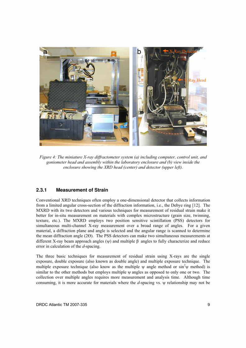
Throughout the investigation, residual strain measurements are made using the Miniature XRD (MXRD) owned by Defence R&D Canada - Atlantic (DRDC Atlantic). This system, shown in Figure 4, was co-developed by DRDC Atlantic and Proto Manufacturing Co. Ltd. specifically for portable in-situ measurement of strain and quantification of stress in metallic components and structures [8]. For the current study, the system was set-up and used within the laboratory enclosure at DRDC Atlantic (Fig 4). Figure 4a shows the miniature X-ray diffractometer system including computer, control unit (lower left) and goniometer head and assembly within the laboratory enclosure. Figure 4b is an inside view of the enclosure showing the XRD head (center) and detector (stainless steel box on upper left).
DRDC Atlantic TM 2007-335 9
Figure 4: The miniature X-ray diffractometer system (a) including computer, control unit, and
goniometer head and assembly within the laboratory enclosure and (b) view inside the
enclosure showing the XRD head (center) and detector (upper left).
2.3.1 Measurement of Strain
Conventional XRD techniques often employ a one-dimensional detector that collects information from a limited angular cross-section of the diffraction information, i.e., the Debye ring [12]. The MXRD with its two detectors and various techniques for measurement of residual strain make it better for in-situ measurement on materials with complex microstructure (grain size, twinning, texture, etc.). The MXRD employs two position sensitive scintillation (PSS) detectors for simultaneous multi-channel X-ray measurement over a broad range of angles. For a given material, a diffraction plane and angle is selected and the angular range is scanned to determine the mean diffraction angle (2 ). The PSS detectors can make two simultaneous measurements at different X-ray beam approach angles ( and multiple angles to fully characterize and reduce error in calculation of the d-spacing.
The three basic techniques for measurement of residual strain using X-rays are the single exposure, double exposure (also known as double angle) and multiple exposure technique. The multiple exposure technique (also know as the multiple angle method or sin2 method) is similar to the other methods but employs multiple angles as opposed to only one or two. The collection over multiple angles requires more measurement and analysis time. Although time consuming, it is more accurate for materials where the d-spacing vs. relationship may not be
a b X-Ray Detector
X-Ray Head
10 DRDC Atlantic TM 2007-335
truly linear (not an issue for the measurements on Q1N steel in this study, but is employed to monitor microstrain). In the multiple angle method, the d-spacing is calculated for the diffraction angle (2 ) and plotted with respect to sin2 . A linear least squares fit of d-spacing with respect to sin2 is determined and the stress is then extracted by calculation of the slope of the line on the graph [8,10]. The deviation from linearity of the data is reflected in the associated error (see Section 4.2.1) and the linearity represents the case predicted by the classical X-ray stress analysis. The linearity and fit of the data provides information on the effects of anisotropy, grain size and the occurrence of non-random grain orientation. These effects, once identified, could be reduced through corrective actions that include modifying fit parameters, increasing aperture size, modifying number and angle of oscillations [12].
2.3.2 Sensitivity and Reproducibility
Instrumental/equipment or specimen-related factors affecting the sensitivity of residual stress analysis by XRD is summarized by Withers and Bhadeshia [13]. In the past few years, there have been many national and international round-robin tests to compare different approaches for determination of residual stress in steels [6, 13-15]. Many of these tests have indicated that the precision of the XRD method is below ± 20 MPa, in excellent agreement with other techniques such as blind hole drilling. In addition, Cullity [6] indicated that the precision of XRD residual stress analysis on steels generally have a standard deviation of 14-20 MPa, but may vary up to 30-35 MPa when peak broadening occurs.
With calibrated equipment and proper techniques the accuracy related to XRD residual stress determination of steels is generally within ± 30 MPa, comparable to measurements determined using the hole drilling method [2]. Improvement of instrumental/equipment accuracy requires calibration of the MXRD, while specimen related errors may be reduced through careful determination of the XREC. This is due to the sensitivity of the X-ray elastic constant to composition (ex., carbon content) and processing (ex., quenching and tempering) conditions.
2.4 Specimen Considerations
A variety of microstructural features can affect the character of the XRD peaks and introduce complications into measurement of strain and calculation of residual stress. The most important features for stress analysis are the phases that are present, grain size and texture, cold work and macro and micro strain. Macroscopic and microscopic strains have been discussed in Section 2.2.2.1 in relation to strain measurement with XRD techniques.
DRDC Atlantic TM 2007-335 11
2.4.1 Phases
Compositional variation (between phases and within a phase), especially carbon content in steel, has a profound effect on the d-spacing and hence, the diffraction angle for the diffraction peaks. For this reason, the two PSS detectors on the MXRD scan a broad range of diffraction angles to capture a specific peak (in this case, the (211) reflection). This makes it useful for phase identification, similar to conventional XRD instruments. The presence of additional peaks may indicate the presence of additional structures, while peak broadening may indicate compositional variation or microstrain. For residual stress analysis, occurrence of additional phases may require separate demarcation of the diffraction lines and separate analysis for each phase. The presence of peak broadening would require explanation and the use of correction factors during residual stress analysis. This needs to be carefully monitored during the course of the investigation.
Residual stress analysis can be challenging when a material is comprised of more than one major crystalline phase. For this situation the residual stress state may be determined as an average of the residual stress of each phase. For example, steels often have a complex microstructure that may contain ferrite, retained austenite, bainite, cementite, martensite, tempered martensite and pearlite among other inclusions. These phases often exist to various degrees depending on composition and thermomechanical processing. Therefore, the conventional practice [4-6,10] is typically to analyse the residual stress in one phase and to consider the stress of that phase equivalent to the stress experienced by the steel as a whole. In some cases, the residual stress is measured for two phases and the net stress is calculated as a weighted average of both phases. A notable example is the analysis of residual stress in martensitic steel with retained austenite [16]. For reasons as discussed below, analysis on two phases was not required for the Q1N steel in this study.
This study examines Q1N steel extracted from the pressure hull of HMCS VICTORIA. Q1N is a high strength/toughness steel, similar to American HY80 steels, that has a minimum yield strength of 550 MPa. Chemical analysis on a specimen in close proximity to the location of specimens used in this study is shown in Table 1 [17]. The concentration of most of the elements falls within the Defence standard specifications for Q1N steel [18]; Si and Al are the exceptions. A metallographic study by Bayley [19] revealed a tempered martensite and bainite microstructure with regions of grain boundary ferrite.
Residual stress analysis on multiphase materials requires careful selection of a specific crystallographic plane for analysis. Often a plane that diffracts at high angle, and of significant intensity, is chosen for better accuracy. These planes exhibit larger shifts in d-spacing for a given amount of strain. In addition, it is best that the diffraction from this plane avoid overlap from diffraction from other phases that could broaden the peak of interest and reduce the accuracy of the stress evaluated. For this investigation, two PSS detectors were set to scan a broad range of diffraction angles (151-165° 2 ) to capture diffraction data produced by the {211} planes of bcc Fe near 156° 2 .
12 DRDC Atlantic TM 2007-335
Table 1: Chemical analysis of a similar specimen of pressure hull Q1N steel [17] and from
Defence standards for Q1N steel [18].
Specimen composition in wt% [17]
Element
Region 1 Region 2
Q1N steel specifications [18]
Carbon 0.17 0.15 0.18
Manganese 0.29 0.31 0.10 0.40
Phosphorous 0.0056 0.013 0.015
Sulfur < 0.0001 0.0009 0.008
Silicon 0.44 0.23 0.15 0.35
Aluminum 0.10 0.029 0.015 0.060
Nickel 2.6 2.9 2.25 3.25
Chromium 1.3 1.4 1.00 1.80
Molybdenum 0.39 0.41 0.2 0.6
Copper 0.031 0.041 0.20
Scanning the broad range of diffraction angles (151-165° 2 ) will also provide information about the crystal structure of the tempered martensite phase. If the bainite or tempered martensite had the bcc structure of Fe and similar carbon content, the XRD pattern would have the same diffraction peaks as the ferrite phase. A reduction of symmetry of the martensite structure (ex., from cubic to tetragonal or orthorhombic) would manifest as splitting of the {211} peak. The {211} diffraction peak would split into a dublet [(211) and (112)] for the tetragonal martensite structure or a triplet [(211), (121) and (112)] for the orthorhombic martensite. The splitting would occur as either discrete peaks or as peak broadening and is typical for high carbon steels where the martensite phase exhibits the lower symmetry structure. Since no peak splitting or broadening was observed over the diffraction angle range used in this study, the bainite and tempered martensite in this Q1N steel is believed to be isostructural to and with the same lattice spacing as ferrite. This assumes that the compositional variation for the phases is below the resolution of the XRD technique. Therefore, residual stress values reflect the deformation experienced by the ferrite, bainite and tempered martensite phases.
Residual stress analysis with XRD becomes more challenging for measurement of residual stress at welds where the thermal history, compositional variation, and mechanical restraint have often resulted in a very complex microstructure of ferrite, martensite, bainite and inclusions. The effects of compositional and microstructural variation are often superimposed to various degrees on the residual stress profile for the weldment and are difficult or impossible to demarcate. The resultant inhomogeneity in elastic properties also makes determination of XREC difficult. A follow-up investigation will look at the effect of temperature and thermal processing on the microstructure and residual stress distribution (see Section 6 on Future Work) in Q1N steel.
DRDC Atlantic TM 2007-335 13
2.4.2 Grain size and Texture
Commercial metals and alloys often contain grain sizes that are in the range from 1 to 1000 m, but the range from 10 to 100 m is more typical. Large grain sizes (> ~100 m) often lead to a condition where there are insufficient grains irradiated by the X-ray beam to produce a continuous cone of diffraction [8]. The Debye rings appears spotty, the diffraction peaks are less intense and the accuracy of the residual stress analysis is affected. Small grains (< 0.1 m) often produce broadening due to the occurrence of non-uniform strains; little is known about this phenomenon [6]. The ideal range of grain size for diffraction measurements is from approximately 0.1 to 10 m, depending on experimental conditions [6]. This range is not typical for commercial steels, but the range may be increased through adjustment of equipment parameters (aperture selection, etc) and peak fitting parameters.
Preferred orientation often occurs during casting or by plastic flow and recrystallization during various processing techniques (i.e., forging, extrusion, rolling). As residual stress is a tensor property, texture generally causes anomalous stress results for XRD measurements. In addition, the occurrence of texture and twinning are problematic for calculations as the anisotropic nature of the XREC leads to non-uniform shifting of diffraction peaks collected at different . Grain size, texture and twinning effects may influence the accuracy, reproducibility, magnitude and sign of the calculated stress unless detected. Through use of collection of strain at multiple angles, these effects will be noticeable. Once identified, they can be overcome with corrective modification of MXRD operational conditions and/or fitting parameters in the residual stress analysis software.
2.4.3 Cold Work
XRD techniques measure the near surface (~ 0.015 mm depth in steel with Cr K radiation) within the depth that processing techniques, such as grinding or polishing, disturb or cold work the surface. Cold working modifies the microstructure, increases crystalline disorder and introduces microstrain and dislocations [8]. This may manifest as peak broadening. Often cold work induces microstructural effects that produce stress fields in the material that must be ascertained and deconvoluted from applied and/or residual stresses of interest. The influence of grinding techniques on residual stress with depth is discussed by Farrell et al. [1] and Prevéy [10].
2.5 The X-Ray Elastic Constant
The XREC is not the bulk elastic modulus of the material. It accounts for the anisotropic nature of elasticity in a material and describes the elastic modulus for a particular set of crystallographic planes, within individual grains, that are oriented perpendicular to the direction of measure. Therefore, the microstructure of the material under investigation often has a significant impact on the XREC. The accuracy of the residual stress analysis method is directly related to the accuracy of the XREC.
14 DRDC Atlantic TM 2007-335
There are a variety of methods that may be employed for determination of the XREC (including resonant ultrasound spectroscopy; single crystal studies and neutron diffraction). For this investigation, the XREC was determined using conventional methods, for example [4-6,10]. These are literature references; experimental measurement of bulk elastic properties in tension and bending; and XRD measurements during four-point bending. In terms of this report, the experimental XREC refers to XRECs that were determined through XRD measurement of Q1N steel under four-point bending carried out in this study. XRECs are termed effective when they are used as an estimate for the Q1N steel and were derived using other steels and/or other methods (other than four-point bending). The term effective does not necessarily reflect the technique through which they were derived but, is employed to differentiate with respect to experimental XRECs determined in this study. The relative merit of each method will be discussed in the following sections and in Section 4.
2.5.1 The Experimental X-Ray Elastic Constant
In this study, the experimental XREC (Eexp) was derived from XRD strain measurement of Q1N steel during four-point bending experiments. The Eexp of a polycrystalline material, like steel, is a function of the stress-strain relation for a specific set of equivalent crystallographic planes {hkl}. For tempered Q1N steel, examined in this study, the {211} crystallographic planes of the bcc Fe crystallographic structure are commonly employed (explained in Section 2.4.1).
The experimental XREC was derived from measurement of the applied stress and change in d-spacing (with MXRD) on the Q1N steel during incremental loading/unloading in four-point bending [3-11]. Detailed experimental procedures are provided in Section 3 and methods for determination of the Eexp are given in Section 4.2. Although the XRD technique is non-destructive, determination of the experimental XREC requires extraction of a specimen for experimental testing. Once complete, the experimental XREC is useful for all residual stress analysis performed on the same material (a change in composition or microstructure may affect the accuracy of measurements). Although experimental XRECs are available in the open literature, they are specific to that particular material and its thermomechanical processing conditions. They are often only suitable as an estimate for similar materials or same material under different processing conditions.
2.5.2 The Effective X-Ray Elastic Constant
The effective XREC (Eeff) may be calculated from the bulk elastic properties of the materials or estimated from literature values. Effective XRECs calculated from applied stress strain curves on the bulk material are insensitive to elastic anisotropy due to crystallographic orientation; unlike the experimental XREC. As such, they are often only useful as estimates and are not expected to provide an accurate determination of residual stress. The effective XREC is often calculated from Young s elastic modulus (E) and Poisson's ratio ( ) according to Equation 6 [4].
DRDC Atlantic TM 2007-335 15
1
EEeff (6)
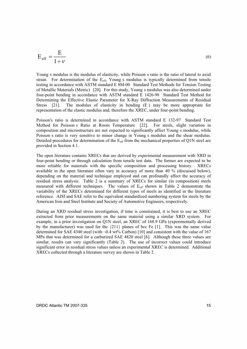
Young s modulus is the modulus of elasticity, while Poisson s ratio is the ratio of lateral to axial strain. For determination of the Eeff, Young s modulus is typically determined from tensile testing in accordance with ASTM standard E 8M-00 Standard Test Methods for Tension Testing of Metallic Materials (Metric) [20]. For this study, Young s modulus was also determined under four-point bending in accordance with ASTM standard E 1426-98 Standard Test Method for Determining the Effective Elastic Parameter for X-Ray Diffraction Measurements of Residual Stress [21]. The modulus of elasticity in bending (E ) may be more appropriate for representation of the elastic modulus and, therefore the XREC, under four-point bending.
Poisson's ratio is determined in accordance with ASTM standard E 132-97 Standard Test Method for Poisson s Ratio at Room Temperature [22]. For steels, slight variation in composition and microstructure are not expected to significantly affect Young s modulus, while Poisson s ratio is very sensitive to minor change in Young s modulus and the shear modulus. Detailed procedures for determination of the Eeff from the mechanical properties of Q1N steel are provided in Section 4.1.
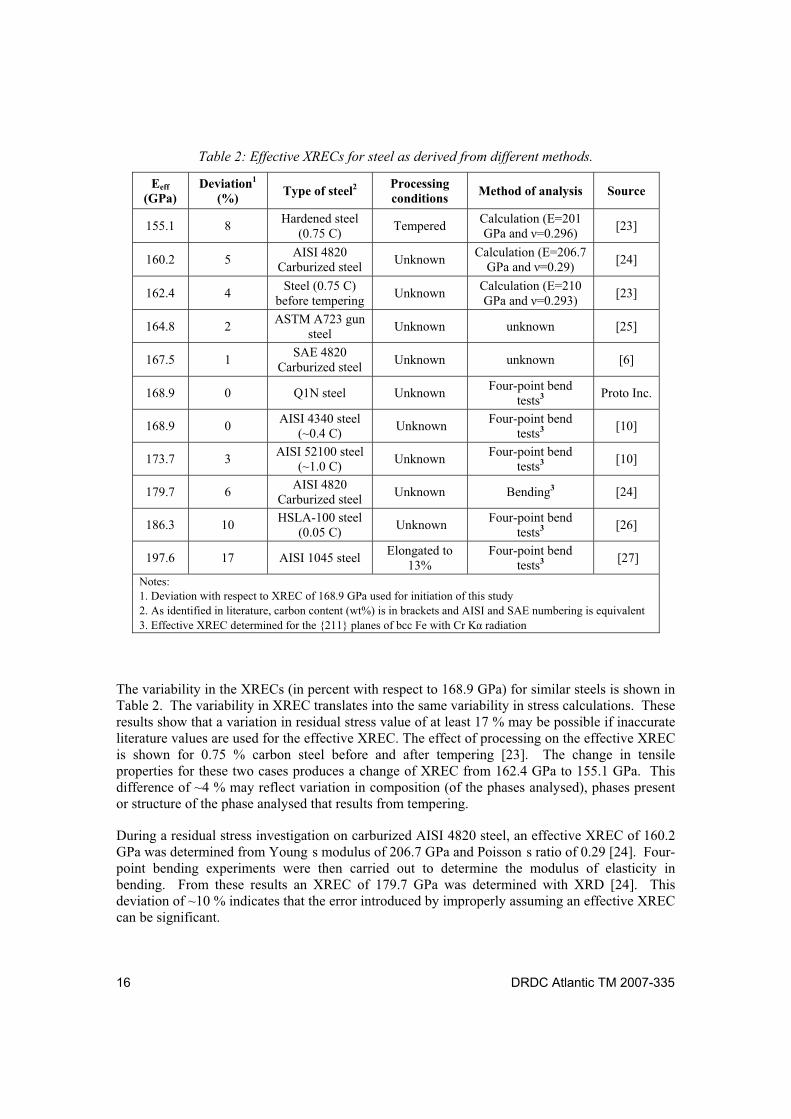
The open literature contains XRECs that are derived by experimental measurement with XRD in four-point bending or through calculation from tensile test data. The former are expected to be more reliable for materials with the specific composition and processing history. XRECs available in the open literature often vary in accuracy of more than 40 % (discussed below), depending on the material and technique employed and can profoundly affect the accuracy of residual stress analysis. Table 2 is a summary of XRECs for similar (in composition) steels measured with different techniques. The values of Eeff shown in Table 2 demonstrate the variability of the XRECs determined for different types of steels as identified in the literature reference. AISI and SAE refer to the equivalent standardized numbering system for steels by the American Iron and Steel Institute and Society of Automotive Engineers, respectively.
During an XRD residual stress investigation, if time is constrained, it is best to use an XREC extracted from prior measurements on the same material using a similar XRD system. For example, in a prior investigation on Q1N steel, an XREC of 168.9 GPa (experimentally derived by the manufacturer) was used for the {211} planes of bcc Fe [1]. This was the same value determined for SAE 4340 steel (with ~0.4 wt% Carbon) [10] and consistent with the value of 167 MPa that was determined for a carburized SAE 4820 steel [6]. Although these three values are similar, results can vary significantly (Table 2). The use of incorrect values could introduce significant error in residual stress values unless an experimental XREC is determined. Additional XRECs collected through a literature survey are shown in Table 2.
16 DRDC Atlantic TM 2007-335
Table 2: Effective XRECs for steel as derived from different methods.
Eeff (GPa)
Deviation1 (%)
Type of steel2 Processing conditions
Method of analysis Source
155.1 8 Hardened steel
(0.75 C) Tempered
Calculation (E=201 GPa and =0.296)
[23]
160.2 5 AISI 4820
Carburized steel Unknown
Calculation (E=206.7 GPa and =0.29)
[24]
162.4 4 Steel (0.75 C)
before tempering Unknown
Calculation (E=210 GPa and =0.293)
[23]
164.8 2 ASTM A723 gun
steel Unknown unknown [25]
167.5 1 SAE 4820
Carburized steel Unknown unknown [6]
168.9 0 Q1N steel Unknown Four-point bend
tests3 Proto Inc.
168.9 0 AISI 4340 steel
(~0.4 C) Unknown
Four-point bend tests3
[10]
173.7 3 AISI 52100 steel
(~1.0 C) Unknown
Four-point bend tests3
[10]
179.7 6 AISI 4820
Carburized steel Unknown Bending3 [24]
186.3 10 HSLA-100 steel
(0.05 C) Unknown
Four-point bend tests3
[26]
197.6 17 AISI 1045 steel Elongated to
13% Four-point bend
tests3 [27]
Notes: 1. Deviation with respect to XREC of 168.9 GPa used for initiation of this study 2. As identified in literature, carbon content (wt%) is in brackets and AISI and SAE numbering is equivalent 3. Effective XREC determined for the {211} planes of bcc Fe with Cr K radiation
The variability in the XRECs (in percent with respect to 168.9 GPa) for similar steels is shown in Table 2. The variability in XREC translates into the same variability in stress calculations. These results show that a variation in residual stress value of at least 17 % may be possible if inaccurate literature values are used for the effective XREC. The effect of processing on the effective XREC is shown for 0.75 % carbon steel before and after tempering [23]. The change in tensile properties for these two cases produces a change of XREC from 162.4 GPa to 155.1 GPa. This difference of ~4 % may reflect variation in composition (of the phases analysed), phases present or structure of the phase analysed that results from tempering.
During a residual stress investigation on carburized AISI 4820 steel, an effective XREC of 160.2 GPa was determined from Young s modulus of 206.7 GPa and Poisson s ratio of 0.29 [24]. Four-point bending experiments were then carried out to determine the modulus of elasticity in bending. From these results an XREC of 179.7 GPa was determined with XRD [24]. This deviation of ~10 % indicates that the error introduced by improperly assuming an effective XREC can be significant.
DRDC Atlantic TM 2007-335 17
A significant observation from many of the investigations in the open literature is the exclusion of information related to the processing conditions and microstructure of the materials investigated. This makes it more difficult to make an accurate choice of an effective XREC from the literature and, as shown in Table 2, errors of more than 17% are possible.
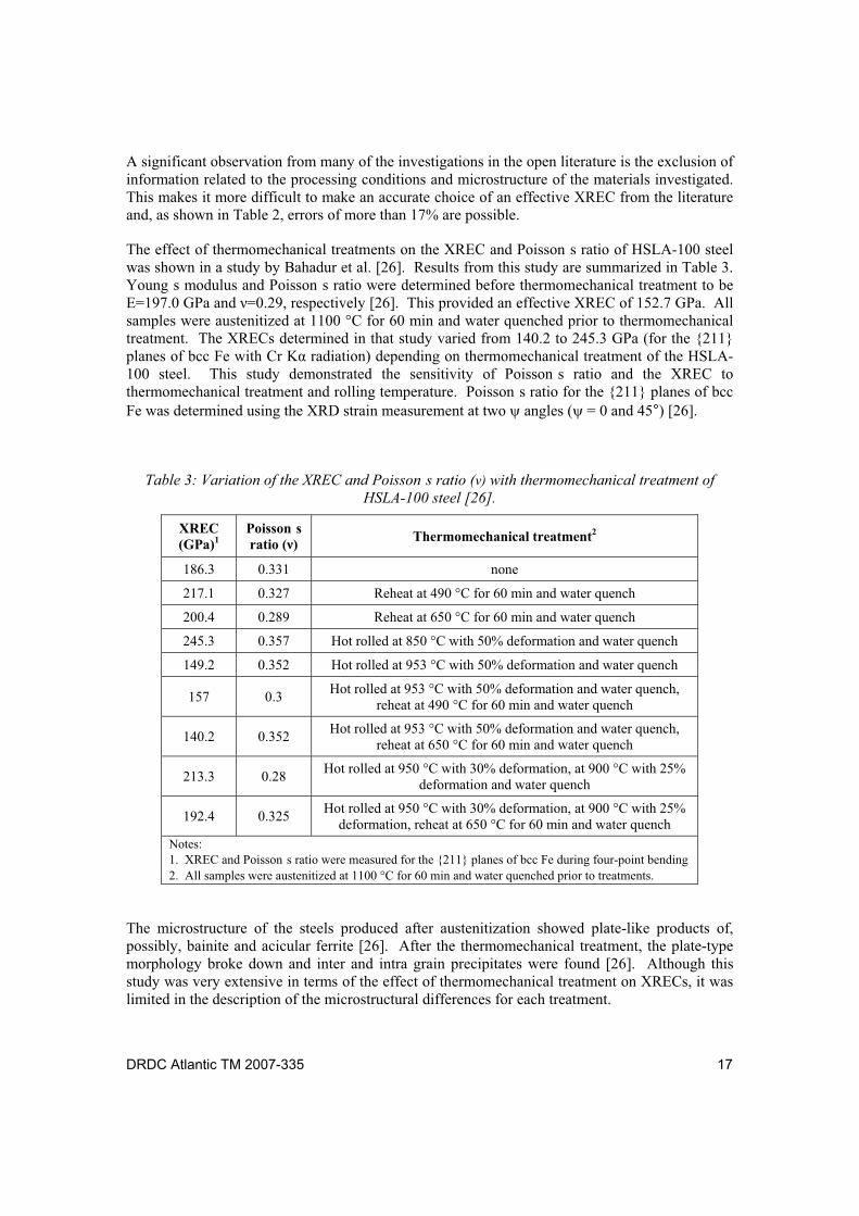
The effect of thermomechanical treatments on the XREC and Poisson s ratio of HSLA-100 steel was shown in a study by Bahadur et al. [26]. Results from this study are summarized in Table 3. Young s modulus and Poisson s ratio were determined before thermomechanical treatment to be E=197.0 GPa and =0.29, respectively [26]. This provided an effective XREC of 152.7 GPa. All samples were austenitized at 1100 °C for 60 min and water quenched prior to thermomechanical treatment. The XRECs determined in that study varied from 140.2 to 245.3 GPa (for the {211} planes of bcc Fe with Cr K radiation) depending on thermomechanical treatment of the HSLA-100 steel. This study demonstrated the sensitivity of Poisson s ratio and the XREC to thermomechanical treatment and rolling temperature. Poisson s ratio for the {211} planes of bcc Fe was determined using the XRD strain measurement at two angles ( = 0 and 45°) [26].
Table 3: Variation of the XREC and Poisson s ratio ( ) with thermomechanical treatment of
HSLA-100 steel [26].
XREC (GPa)1
Poisson s ratio ( )
Thermomechanical treatment2
186.3 0.331 none
217.1 0.327 Reheat at 490 °C for 60 min and water quench
200.4 0.289 Reheat at 650 °C for 60 min and water quench
245.3 0.357 Hot rolled at 850 °C with 50% deformation and water quench
149.2 0.352 Hot rolled at 953 °C with 50% deformation and water quench
157 0.3 Hot rolled at 953 °C with 50% deformation and water quench,
reheat at 490 °C for 60 min and water quench
140.2 0.352 Hot rolled at 953 °C with 50% deformation and water quench,
reheat at 650 °C for 60 min and water quench
213.3 0.28 Hot rolled at 950 °C with 30% deformation, at 900 °C with 25%
deformation and water quench
192.4 0.325 Hot rolled at 950 °C with 30% deformation, at 900 °C with 25%
deformation, reheat at 650 °C for 60 min and water quench
Notes: 1. XREC and Poisson s ratio were measured for the {211} planes of bcc Fe during four-point bending 2. All samples were austenitized at 1100 °C for 60 min and water quenched prior to treatments.
The microstructure of the steels produced after austenitization showed plate-like products of, possibly, bainite and acicular ferrite [26]. After the thermomechanical treatment, the plate-type morphology broke down and inter and intra grain precipitates were found [26]. Although this study was very extensive in terms of the effect of thermomechanical treatment on XRECs, it was limited in the description of the microstructural differences for each treatment.
18 DRDC Atlantic TM 2007-335
This variability of the XREC in the open literature demonstrates the need for experimental derivation of the XREC from a specimen of the same composition and microstructure (phase, grain size, temperature, deformation history, etc.) as the material to be investigated. It is unfortunate that many studies found in the open literature fail to derive the experimental XREC and tend to rely on literature values. In other situations, the studies do not identify the XREC used for analysis at all. Although the XRD technique is non-destructive, improved accuracy of the technique requires a suitable specimen for determination of the experimental XREC. Often this must be extracted from the material under investigation.
DRDC Atlantic TM 2007-335 19
3 Experimental Methods
The accuracy and precision of XRD residual stress analysis depends on the methods employed for measurement of strain and calculation of stress from strain values. The latter will be examined in detail in Section 4. The following experimental methods detail the procedures employed to prepare test specimens, perform four-point bend tests, and accurately measure strain (by strain gauge and MXRD) on Q1N steel specimens. As the experimental procedures for determination of Young s modulus and Poisson are adequately described by ASTM standards [20-22], they will not be described in detail and will be covered in the results section (Section 4.1).
3.1 Preparation of Tempered Q1N Steel Specimens
Test specimens were made from tempered Q1N steel from the extracted pressure hull plate of HMCS VICTORIA, between frames 31 and 32 and the 1st and 3rd decks. The long dimension of the specimens represents the axial direction of the pressure hull plate on the submarine, while the intermediate and short dimensions represent the hoop and thickness direction, respectively. An electrical discharge machine was used to cut the specimens for the experiments.
3.1.1 Tensile Specimens
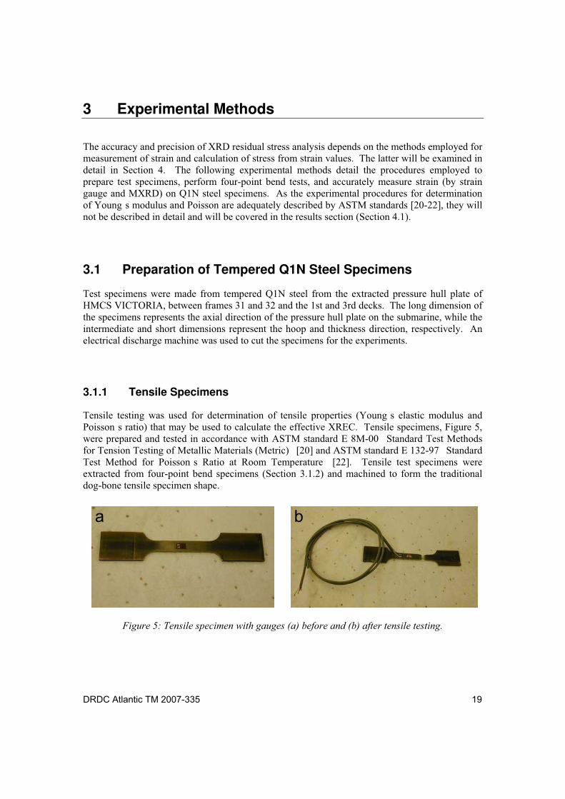
Tensile testing was used for determination of tensile properties (Young s elastic modulus and Poisson s ratio) that may be used to calculate the effective XREC. Tensile specimens, Figure 5, were prepared and tested in accordance with ASTM standard E 8M-00 Standard Test Methods for Tension Testing of Metallic Materials (Metric) [20] and ASTM standard E 132-97 Standard Test Method for Poisson s Ratio at Room Temperature [22]. Tensile test specimens were extracted from four-point bend specimens (Section 3.1.2) and machined to form the traditional dog-bone tensile specimen shape.
Figure 5: Tensile specimen with gauges (a) before and (b) after tensile testing.
a b
20 DRDC Atlantic TM 2007-335
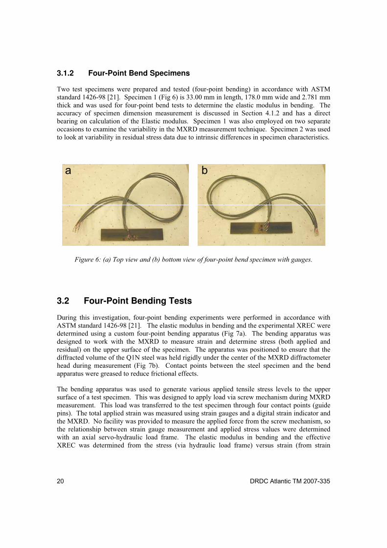
3.1.2 Four-Point Bend Specimens
Two test specimens were prepared and tested (four-point bending) in accordance with ASTM standard 1426-98 [21]. Specimen 1 (Fig 6) is 33.00 mm in length, 178.0 mm wide and 2.781 mm thick and was used for four-point bend tests to determine the elastic modulus in bending. The accuracy of specimen dimension measurement is discussed in Section 4.1.2 and has a direct bearing on calculation of the Elastic modulus. Specimen 1 was also employed on two separate occasions to examine the variability in the MXRD measurement technique. Specimen 2 was used to look at variability in residual stress data due to intrinsic differences in specimen characteristics.
Figure 6: (a) Top view and (b) bottom view of four-point bend specimen with gauges.
3.2 Four-Point Bending Tests
During this investigation, four-point bending experiments were performed in accordance with ASTM standard 1426-98 [21]. The elastic modulus in bending and the experimental XREC were determined using a custom four-point bending apparatus (Fig 7a). The bending apparatus was designed to work with the MXRD to measure strain and determine stress (both applied and residual) on the upper surface of the specimen. The apparatus was positioned to ensure that the diffracted volume of the Q1N steel was held rigidly under the center of the MXRD diffractometer head during measurement (Fig 7b). Contact points between the steel specimen and the bend apparatus were greased to reduce frictional effects.
The bending apparatus was used to generate various applied tensile stress levels to the upper surface of a test specimen. This was designed to apply load via screw mechanism during MXRD measurement. This load was transferred to the test specimen through four contact points (guide pins). The total applied strain was measured using strain gauges and a digital strain indicator and the MXRD. No facility was provided to measure the applied force from the screw mechanism, so the relationship between strain gauge measurement and applied stress values were determined with an axial servo-hydraulic load frame. The elastic modulus in bending and the effective XREC was determined from the stress (via hydraulic load frame) versus strain (from strain
a b
DRDC Atlantic TM 2007-335 21
gauges) relations under four-point bending. Similarly, the four point bend apparatus was used to determine the experimental XREC from stress (calculated from strain gauges data and elastic constant) versus strain (as measured by the MXRD) analysis.
Figure 7: (a) Four-point bend apparatus with gauged Q1N steel and (b) under the head of
the MXRD.
3.2.1 Strain Measurement
Strain gauges were attached to the Q1N steel specimen to measure strain parallel to the longitudinal axis in the region that experiences the maximum deflection (Fig 6). Therefore, strain gauges were attached at half the length of the specimen (see schematic in Fig 8). In this configuration, the area under the MXRD and the area with gauge 1 (channel 1; Fig 6a) should experience the same strain. Similarly, two gauges were placed on the underside of the specimen, in similar locations. These strain gauges (shown in Fig 6b: gauge 2 (channel 2) and gauge 3 (channel 3)) should have readings that are similar (but opposite in sign) to those from gauge 1. This provides a measure of inhomogeneous strain or shear on the specimen during measurement.
The effective strain at the MXRD location ( eff) was calculated using Equation 7 to average the strain at each gauge location (channels 1-3). The strain at each gauge should vary in sign; a positive strain value indicates tensile strain while the negative values indicate compressive strain.
3channel2channel1channeleff (7)
a b
22 DRDC Atlantic TM 2007-335
Figure 8: Schematic showing location of gauge 1 (rectangle) and area of MXRD measurement
(oval) on the top of Q1N specimens. Note: other gauges are at similar locations on the underside
of the specimen.
3.2.2 Specimen Pre-Loading
A pre-loading technique was employed to minimize drift in the gauges and creep in strain gauge adhesive during subsequent measurement. Before measurement, specimens were incrementally loaded to near 75% (~2000 x 10-6 strain) of the yield stress and unloaded. This was repeated several times. The stress (residual and applied, from MXRD) and applied strain were then measured with incremental loading and unloading for several cycles.
3.2.3 Four-Point Bending Experiments
Q1N steel specimens were placed on the four-point bend apparatus and placed under the MXRD diffractometer (Fig 7b). Specimens were incrementally loaded and unloaded using the screw mechanism. The stress was determined with the MXRD as a function of applied strain (gauges) during incremental loading and unloading. An XREC of 168.9 GPa, used for previous measurement on Q1N steel, was employed for residual stress calculations. The MXRD stress (residual and applied) and applied strain data was examined for linearity and repeatability. Stress and strain data were not collected below 200 x 10-6 strain as the data could be influenced by surface effects which are less significant at higher strain. Results are discussed in Section 4.2.1.
3.2.4 Applied Load
The relationship between strain gauge measurement and applied stress values were determined with the axial servo-hydraulic load frame. This provides a measure of the modulus of elasticity in bending. Strain-gauged specimens were placed within the bending apparatus and the assembly was inserted into the axial servo-hydraulic load frame. The screw mechanism used to mechanically apply loads was removed to allow the load frame to incrementally load the specimen. The applied strain was measured as a function of engineering stress for several cycles
1/3
1/3
1/3
½ length ½ length
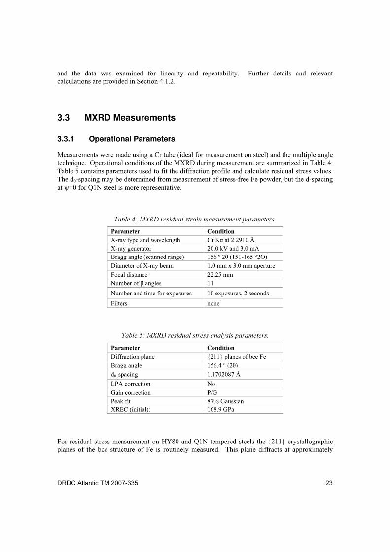
DRDC Atlantic TM 2007-335 23
and the data was examined for linearity and repeatability. Further details and relevant calculations are provided in Section 4.1.2.
3.3 MXRD Measurements
3.3.1 Operational Parameters
Measurements were made using a Cr tube (ideal for measurement on steel) and the multiple angle technique. Operational conditions of the MXRD during measurement are summarized in Table 4. Table 5 contains parameters used to fit the diffraction profile and calculate residual stress values. The d0-spacing may be determined from measurement of stress-free Fe powder, but the d-spacing at =0 for Q1N steel is more representative.
Table 4: MXRD residual strain measurement parameters.
Parameter Condition
X-ray type and wavelength Cr K at 2.2910 Å
X-ray generator 20.0 kV and 3.0 mA
Bragg angle (scanned range) 156 º 2 (151-165 °2 )
Diameter of X-ray beam 1.0 mm x 3.0 mm aperture
Focal distance 22.25 mm
Number of angles 11
Number and time for exposures 10 exposures, 2 seconds
Filters none
Table 5: MXRD residual stress analysis parameters.
Parameter Condition
Diffraction plane {211} planes of bcc Fe
Bragg angle 156.4 ° (2 )
d0-spacing 1.1702087 Å
LPA correction No
Gain correction P/G
Peak fit 87% Gaussian
XREC (initial): 168.9 GPa
For residual stress measurement on HY80 and Q1N tempered steels the {211} crystallographic planes of the bcc structure of Fe is routinely measured. This plane diffracts at approximately
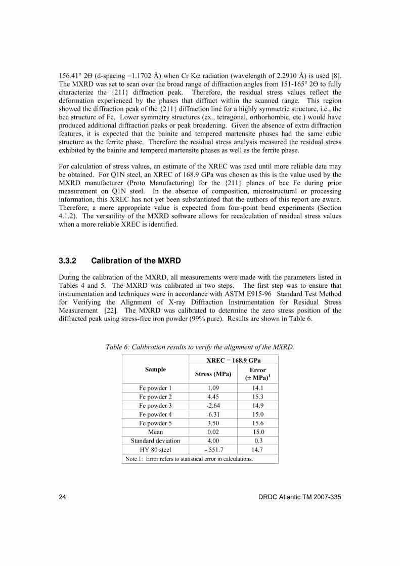
24 DRDC Atlantic TM 2007-335
156.41° 2 (d-spacing =1.1702 Å) when Cr K radiation (wavelength of 2.2910 Å) is used [8]. The MXRD was set to scan over the broad range of diffraction angles from 151-165° 2 to fully characterize the {211} diffraction peak. Therefore, the residual stress values reflect the deformation experienced by the phases that diffract within the scanned range. This region showed the diffraction peak of the {211} diffraction line for a highly symmetric structure, i.e., the bcc structure of Fe. Lower symmetry structures (ex., tetragonal, orthorhombic, etc.) would have produced additional diffraction peaks or peak broadening. Given the absence of extra diffraction features, it is expected that the bainite and tempered martensite phases had the same cubic structure as the ferrite phase. Therefore the residual stress analysis measured the residual stress exhibited by the bainite and tempered martensite phases as well as the ferrite phase.
For calculation of stress values, an estimate of the XREC was used until more reliable data may be obtained. For Q1N steel, an XREC of 168.9 GPa was chosen as this is the value used by the MXRD manufacturer (Proto Manufacturing) for the {211} planes of bcc Fe during prior measurement on Q1N steel. In the absence of composition, microstructural or processing information, this XREC has not yet been substantiated that the authors of this report are aware. Therefore, a more appropriate value is expected from four-point bend experiments (Section 4.1.2). The versatility of the MXRD software allows for recalculation of residual stress values when a more reliable XREC is identified.
3.3.2 Calibration of the MXRD
During the calibration of the MXRD, all measurements were made with the parameters listed in Tables 4 and 5. The MXRD was calibrated in two steps. The first step was to ensure that instrumentation and techniques were in accordance with ASTM E915-96 Standard Test Method for Verifying the Alignment of X-ray Diffraction Instrumentation for Residual Stress Measurement [22]. The MXRD was calibrated to determine the zero stress position of the diffracted peak using stress-free iron powder (99% pure). Results are shown in Table 6.
Table 6: Calibration results to verify the alignment of the MXRD.
XREC = 168.9 GPa
Sample Stress (MPa)
Error (± MPa)1
Fe powder 1 1.09 14.1
Fe powder 2 4.45 15.3
Fe powder 3 -2.64 14.9
Fe powder 4 -6.31 15.0
Fe powder 5 3.50 15.6
Mean 0.02 15.0
Standard deviation 4.00 0.3
HY 80 steel - 551.7 14.7
Note 1: Error refers to statistical error in calculations.
DRDC Atlantic TM 2007-335 25
The measurements on iron powder fell within ASTM E915-96 specifications (arithmetic mean of ± 14 MPa with a standard deviation of ± 14 MPa) [22]. Deviation from specifications would have indicated possible alignment issues with the MXRD that would need correction. Periodic measurements were performed on the iron powder to verify that calibration was maintained during the course of the study. The relatively low stress and standard deviation from these results suggest that measurements are within ASTM specifications and would still meet these standards even if the XREC was double that used under the present conditions.
The second step of the calibration ensured that measurements were reproducible for larger scale residual stress values. This involved residual stress analysis on a known standard similar to the material under investigation. For measurement on Q1N steel, a piece of HY80 steel supplied and characterized by the equipment manufacturer was used. A specific location on the standard was measured with a similar MXRD using the same conditions listed in Tables 4 and 5: a value of 168.9 GPa was used for the XREC. Results for the HY80 standard, from the manufacturer, had indicated a residual stress of -540 MPa (± 20 MPa). The HY80 standard was measured using the same conditions as the manufacturer used and was shown to exhibit a residual stress of -551.7 MPa. This was well within the limits expected for X-ray diffraction equipment. In the future, more reliable residual stress calibrations will employ materials that have been accurately measured using other techniques such as neutron diffraction.
Precision of the residual stress analysis was estimated by repeating a measurement several times at the same location, while repositioning and refocusing the MXRD between measurements. For this analysis, residual stress values were determined on Q1N steel in tension using the four-point bend apparatus. The results at ~2000 microstrain (from strain gauges) produced 3 similar stress values (536.1, 534.3 and 537.3 MPa) with an average of 535.9 MPa and a standard deviation of 1.2 MPa. This difference of less than 1% demonstrates the reproducibility of the XRD residual stress analysis technique.
Although these results provide a reasonable indication of the accuracy of the equipment, a better estimate of the accuracy merits further investigation. Previous studies in the literature had indicated an accuracy and precision for residual stress analysis using XRD (for steels) of ~ ±30 MPa and ±20 MPa, respectively [1,2,6]. These results provide a more conservative estimate of the precision and accuracy of the MXRD. Given the reliance of the residual stress analysis technique on the value of the XREC used for measurement, strain standards may provide a better estimate of the accuracy of measurement. Further investigation of the accuracy and precision is merited and will be forthcoming.
26 DRDC Atlantic TM 2007-335
4 Determination of X-Ray Elastic Constants
The preceding section provides some insight into the instrumental accuracy and precision of the portable MXRD for measurements. Another important factor affecting residual stress analysis accuracy is the method for determination of the XREC used for calculation of stress from strain values. This section provides the results from several techniques used for determination of the XREC.
In the following sections, several methods will be used to determine the XREC and the results will be compared. The first section focuses on determination of the effective XREC (Eeff) using previous experiments (manufacturer/supplier information), literature values and experimental tensile testing data. The latter focuses on 1 experimental method and 2 analysis techniques for determination of the experimental XREC (Eexp). Results for the different techniques will be discussed and an appropriate procedure for accurate determination of the XREC, and hence, residual stress values, for future investigations will be proposed.
4.1 The Effective XREC
Effective XRECs were derived from literature values determined using XRD and four-point bending experiments (for the {211} crystallographic planes of bcc Fe using Cr K radiation) or from calculation from tensile properties (Table 2). The effective XREC (for the {211} planes of bcc Fe using Cr K radiation) was determined in previous measurements on Q1N steel (by the manufacturer/supplier) to be 168.9 GPa (Section 3.3). The same XREC was found for SAE 4340 steel (with ~0.4 wt% Carbon) [10], that had a similar composition to Q1N steel (~0.16 wt% Carbon) [17]. These values were consistent with the value of 167 MPa that was determined for carburized SAE 4820 steel; Table 2 [6]. A similar experimental technique for determination of the experimental XREC was performed on a specimen of ferritic ASTM A723 gun steel [25]. From this study, a similar value of 164.8 GPa was determined [25]. The similarity of results for these comparable materials provided support for the use of 168.9 GPa as an effective XREC to initiate residual stress analysis.
With the exception of the study by Bahadur et al. [26], the open literature is fairly limited in terms of correlation of XREC with thermomechanical processing and microstructural evaluations. This is unfortunate, as this study [26] clearly demonstrates the dependence of the XREC on thermomechanical processing and microstructure of steels. It also shows the need for extracting the XREC from a specimen of the same composition and microstructure as the material to be investigated. Given the sensitivity of the XREC to composition and processing conditions, a more reliable effective XREC may be expected through experimental measurement (tensile and four-point bend tests) on the material to be investigated.
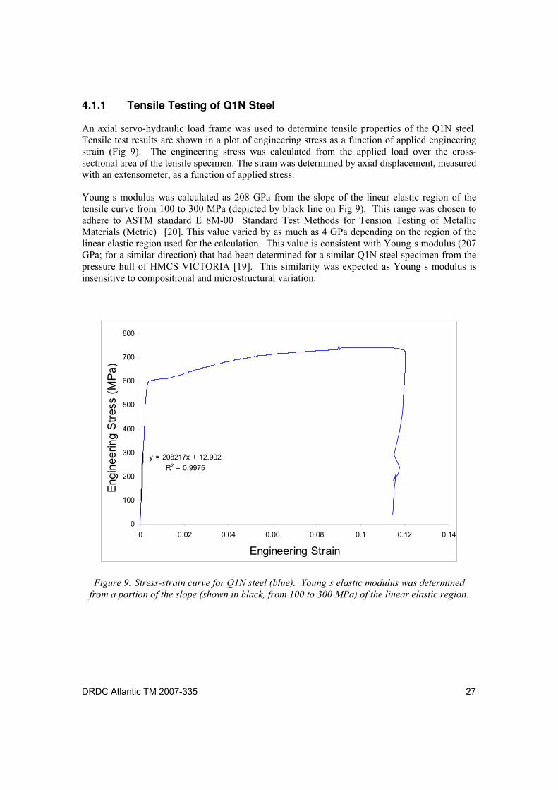
DRDC Atlantic TM 2007-335 27
4.1.1 Tensile Testing of Q1N Steel
An axial servo-hydraulic load frame was used to determine tensile properties of the Q1N steel. Tensile test results are shown in a plot of engineering stress as a function of applied engineering strain (Fig 9). The engineering stress was calculated from the applied load over the cross-sectional area of the tensile specimen. The strain was determined by axial displacement, measured with an extensometer, as a function of applied stress.
Young s modulus was calculated as 208 GPa from the slope of the linear elastic region of the tensile curve from 100 to 300 MPa (depicted by black line on Fig 9). This range was chosen to adhere to ASTM standard E 8M-00 Standard Test Methods for Tension Testing of Metallic Materials (Metric) [20]. This value varied by as much as 4 GPa depending on the region of the linear elastic region used for the calculation. This value is consistent with Young s modulus (207 GPa; for a similar direction) that had been determined for a similar Q1N steel specimen from the pressure hull of HMCS VICTORIA [19]. This similarity was expected as Young s modulus is insensitive to compositional and microstructural variation.
y = 208217x + 12.902
R2 = 0.9975
0
100
200
300
400
500
600
700
800
0 0.02 0.04 0.06 0.08 0.1 0.12 0.14
Engineering Strain
Engin
eering S
tress
(M
Pa)
Figure 9: Stress-strain curve for Q1N steel (blue). Young s elastic modulus was determined
from a portion of the slope (shown in black, from 100 to 300 MPa) of the linear elastic region.
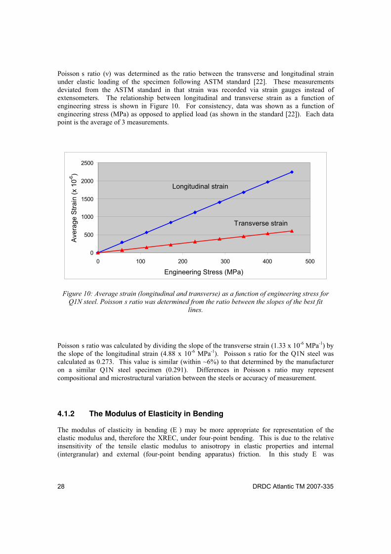
28 DRDC Atlantic TM 2007-335
Poisson s ratio ( ) was determined as the ratio between the transverse and longitudinal strain under elastic loading of the specimen following ASTM standard [22]. These measurements deviated from the ASTM standard in that strain was recorded via strain gauges instead of extensometers. The relationship between longitudinal and transverse strain as a function of engineering stress is shown in Figure 10. For consistency, data was shown as a function of engineering stress (MPa) as opposed to applied load (as shown in the standard [22]). Each data point is the average of 3 measurements.
0
500
1000
1500
2000
2500
0 100 200 300 400 500
Engineering Stress (MPa)
Ave
rag
e S
tra
in (
x 1
0-6)
Transverse strain
Longitudinal strain
Figure 10: Average strain (longitudinal and transverse) as a function of engineering stress for
Q1N steel. Poisson s ratio was determined from the ratio between the slopes of the best fit
lines.
Poisson s ratio was calculated by dividing the slope of the transverse strain (1.33 x 10⁻⁶ MPa-1) by the slope of the longitudinal strain (4.88 x 10⁻⁶ MPa-1). Poisson s ratio for the Q1N steel was calculated as 0.273. This value is similar (within ~6%) to that determined by the manufacturer on a similar Q1N steel specimen (0.291). Differences in Poisson s ratio may represent compositional and microstructural variation between the steels or accuracy of measurement.
4.1.2 The Modulus of Elasticity in Bending
The modulus of elasticity in bending (E ) may be more appropriate for representation of the elastic modulus and, therefore the XREC, under four-point bending. This is due to the relative insensitivity of the tensile elastic modulus to anisotropy in elastic properties and internal (intergranular) and external (four-point bending apparatus) friction. In this study E was
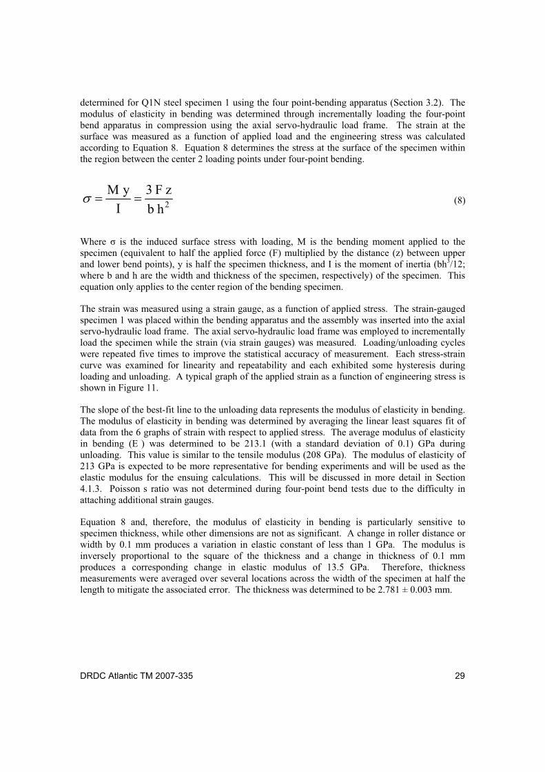
DRDC Atlantic TM 2007-335 29
determined for Q1N steel specimen 1 using the four point-bending apparatus (Section 3.2). The modulus of elasticity in bending was determined through incrementally loading the four-point bend apparatus in compression using the axial servo-hydraulic load frame. The strain at the surface was measured as a function of applied load and the engineering stress was calculated according to Equation 8. Equation 8 determines the stress at the surface of the specimen within the region between the center 2 loading points under four-point bending.
2hb
zF3
I
yM (8)
Where is the induced surface stress with loading, M is the bending moment applied to the specimen (equivalent to half the applied force (F) multiplied by the distance (z) between upper and lower bend points), y is half the specimen thickness, and I is the moment of inertia (bh3/12; where b and h are the width and thickness of the specimen, respectively) of the specimen. This equation only applies to the center region of the bending specimen.
The strain was measured using a strain gauge, as a function of applied stress. The strain-gauged specimen 1 was placed within the bending apparatus and the assembly was inserted into the axial servo-hydraulic load frame. The axial servo-hydraulic load frame was employed to incrementally load the specimen while the strain (via strain gauges) was measured. Loading/unloading cycles were repeated five times to improve the statistical accuracy of measurement. Each stress-strain curve was examined for linearity and repeatability and each exhibited some hysteresis during loading and unloading. A typical graph of the applied strain as a function of engineering stress is shown in Figure 11.
The slope of the best-fit line to the unloading data represents the modulus of elasticity in bending. The modulus of elasticity in bending was determined by averaging the linear least squares fit of data from the 6 graphs of strain with respect to applied stress. The average modulus of elasticity in bending (E ) was determined to be 213.1 (with a standard deviation of 0.1) GPa during unloading. This value is similar to the tensile modulus (208 GPa). The modulus of elasticity of 213 GPa is expected to be more representative for bending experiments and will be used as the elastic modulus for the ensuing calculations. This will be discussed in more detail in Section 4.1.3. Poisson s ratio was not determined during four-point bend tests due to the difficulty in attaching additional strain gauges.
Equation 8 and, therefore, the modulus of elasticity in bending is particularly sensitive to specimen thickness, while other dimensions are not as significant. A change in roller distance or width by 0.1 mm produces a variation in elastic constant of less than 1 GPa. The modulus is inversely proportional to the square of the thickness and a change in thickness of 0.1 mm produces a corresponding change in elastic modulus of 13.5 GPa. Therefore, thickness measurements were averaged over several locations across the width of the specimen at half the length to mitigate the associated error. The thickness was determined to be 2.781 ± 0.003 mm.
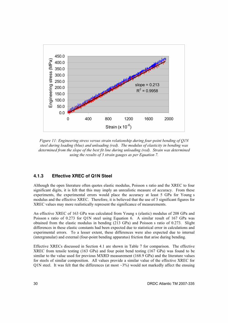
30 DRDC Atlantic TM 2007-335
slope = 0.213
R2 = 0.9958
0.0
50.0
100.0
150.0
200.0
250.0
300.0
350.0
400.0
450.0
0 400 800 1200 1600 2000
Strain (x 10-6)
En
gin
ee
rin
g s
tre
ss (
MP
a)
Figure 11: Engineering stress versus strain relationship during four-point bending of Q1N
steel during loading (blue) and unloading (red). The modulus of elasticity in bending was
determined from the slope of the best fit line during unloading (red). Strain was determined
using the results of 3 strain gauges as per Equation 7.
4.1.3 Effective XREC of Q1N Steel
Although the open literature often quotes elastic modulus, Poisson s ratio and the XREC to four significant digits, it is felt that this may imply an unrealistic measure of accuracy. From these experiments, the experimental errors would place the accuracy at least 5 GPa for Young s modulus and the effective XREC. Therefore, it is believed that the use of 3 significant figures for XREC values may more realistically represent the significance of measurements.
An effective XREC of 163 GPa was calculated from Young s (elastic) modulus of 208 GPa and Poisson s ratio of 0.273 for Q1N steel using Equation 6. A similar result of 167 GPa was obtained from the elastic modulus in bending (213 GPa) and Poisson s ratio of 0.273. Slight differences in these elastic constants had been expected due to statistical error in calculations and experimental errors. To a lesser extent, these differences were also expected due to internal (intergranular) and external (four-point bending apparatus) friction that arise during bending.
Effective XRECs discussed in Section 4.1 are shown in Table 7 for comparison. The effective XREC from tensile testing (163 GPa) and four point bend testing (167 GPa) was found to be similar to the value used for previous MXRD measurement (168.9 GPa) and the literature values for steels of similar composition. All values provide a similar value of the effective XREC for Q1N steel. It was felt that the differences (at most ~3%) would not markedly affect the ensuing
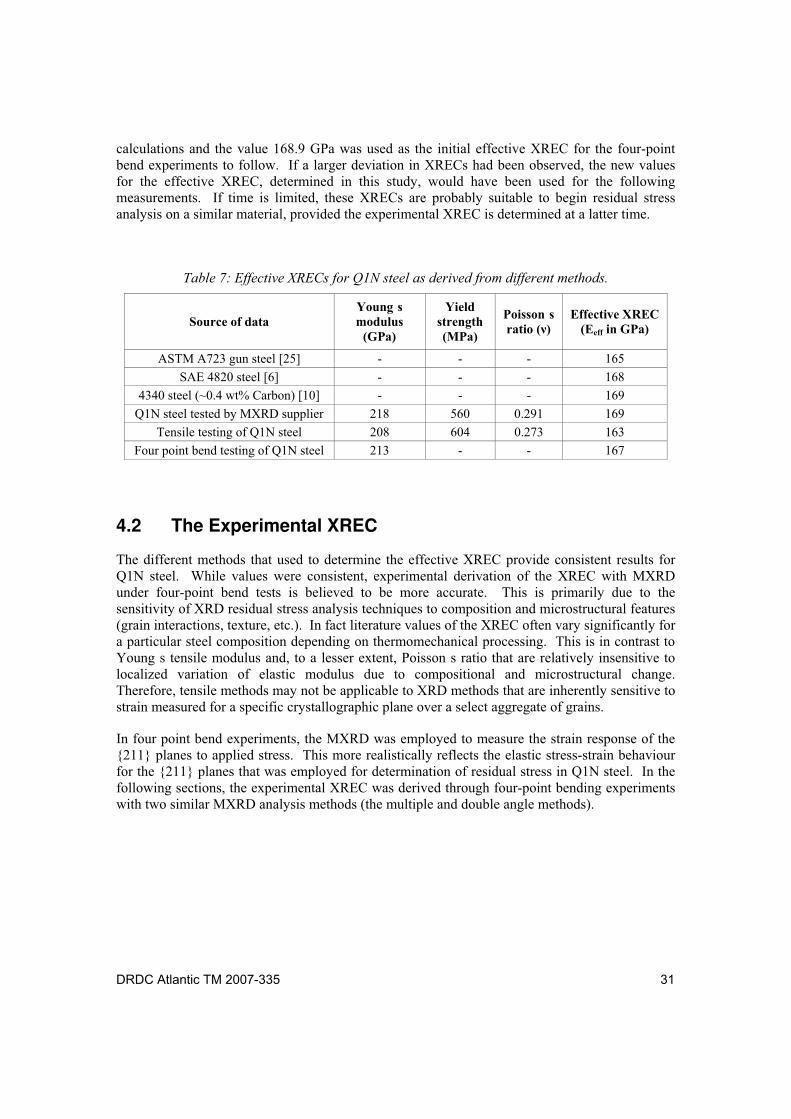
DRDC Atlantic TM 2007-335 31
calculations and the value 168.9 GPa was used as the initial effective XREC for the four-point bend experiments to follow. If a larger deviation in XRECs had been observed, the new values for the effective XREC, determined in this study, would have been used for the following measurements. If time is limited, these XRECs are probably suitable to begin residual stress analysis on a similar material, provided the experimental XREC is determined at a latter time.
Table 7: Effective XRECs for Q1N steel as derived from different methods.
Source of data Young s modulus
(GPa)
Yield strength (MPa)
Poisson s ratio ( )
Effective XREC (Eeff in GPa)
ASTM A723 gun steel [25] - - - 165
SAE 4820 steel [6] - - - 168
4340 steel (~0.4 wt% Carbon) [10] - - - 169
Q1N steel tested by MXRD supplier 218 560 0.291 169
Tensile testing of Q1N steel 208 604 0.273 163
Four point bend testing of Q1N steel 213 - - 167
4.2 The Experimental XREC
The different methods that used to determine the effective XREC provide consistent results for Q1N steel. While values were consistent, experimental derivation of the XREC with MXRD under four-point bend tests is believed to be more accurate. This is primarily due to the sensitivity of XRD residual stress analysis techniques to composition and microstructural features (grain interactions, texture, etc.). In fact literature values of the XREC often vary significantly for a particular steel composition depending on thermomechanical processing. This is in contrast to Young s tensile modulus and, to a lesser extent, Poisson s ratio that are relatively insensitive to localized variation of elastic modulus due to compositional and microstructural change. Therefore, tensile methods may not be applicable to XRD methods that are inherently sensitive to strain measured for a specific crystallographic plane over a select aggregate of grains.
In four point bend experiments, the MXRD was employed to measure the strain response of the {211} planes to applied stress. This more realistically reflects the elastic stress-strain behaviour for the {211} planes that was employed for determination of residual stress in Q1N steel. In the following sections, the experimental XREC was derived through four-point bending experiments with two similar MXRD analysis methods (the multiple and double angle methods).
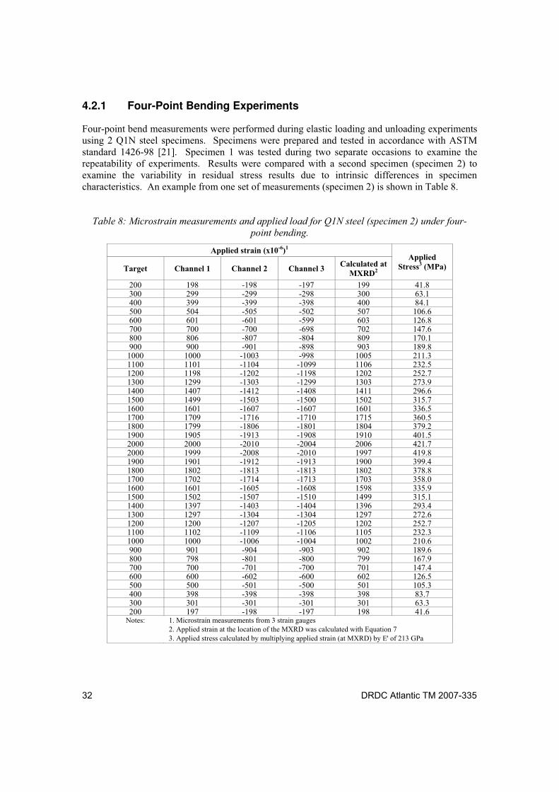
32 DRDC Atlantic TM 2007-335
4.2.1 Four-Point Bending Experiments
Four-point bend measurements were performed during elastic loading and unloading experiments using 2 Q1N steel specimens. Specimens were prepared and tested in accordance with ASTM standard 1426-98 [21]. Specimen 1 was tested during two separate occasions to examine the repeatability of experiments. Results were compared with a second specimen (specimen 2) to examine the variability in residual stress results due to intrinsic differences in specimen characteristics. An example from one set of measurements (specimen 2) is shown in Table 8.
Table 8: Microstrain measurements and applied load for Q1N steel (specimen 2) under four-
point bending.
Applied strain (x10-6)1
Target Channel 1 Channel 2 Channel 3 Calculated at
MXRD2
Applied Stress3 (MPa)
200 198 -198 -197 199 41.8 300 299 -299 -298 300 63.1 400 399 -399 -398 400 84.1 500 504 -505 -502 507 106.6 600 601 -601 -599 603 126.8 700 700 -700 -698 702 147.6 800 806 -807 -804 809 170.1 900 900 -901 -898 903 189.8 1000 1000 -1003 -998 1005 211.3 1100 1101 -1104 -1099 1106 232.5 1200 1198 -1202 -1198 1202 252.7 1300 1299 -1303 -1299 1303 273.9 1400 1407 -1412 -1408 1411 296.6 1500 1499 -1503 -1500 1502 315.7 1600 1601 -1607 -1607 1601 336.5 1700 1709 -1716 -1710 1715 360.5 1800 1799 -1806 -1801 1804 379.2 1900 1905 -1913 -1908 1910 401.5 2000 2000 -2010 -2004 2006 421.7 2000 1999 -2008 -2010 1997 419.8 1900 1901 -1912 -1913 1900 399.4 1800 1802 -1813 -1813 1802 378.8 1700 1702 -1714 -1713 1703 358.0 1600 1601 -1605 -1608 1598 335.9 1500 1502 -1507 -1510 1499 315.1 1400 1397 -1403 -1404 1396 293.4 1300 1297 -1304 -1304 1297 272.6 1200 1200 -1207 -1205 1202 252.7 1100 1102 -1109 -1106 1105 232.3 1000 1000 -1006 -1004 1002 210.6 900 901 -904 -903 902 189.6 800 798 -801 -800 799 167.9 700 700 -701 -700 701 147.4 600 600 -602 -600 602 126.5 500 500 -501 -500 501 105.3 400 398 -398 -398 398 83.7 300 301 -301 -301 301 63.3 200 197 -198 -197 198 41.6
Notes: 1. Microstrain measurements from 3 strain gauges 2. Applied strain at the location of the MXRD was calculated with Equation 7 3. Applied stress calculated by multiplying applied strain (at MXRD) by E' of 213 GPa
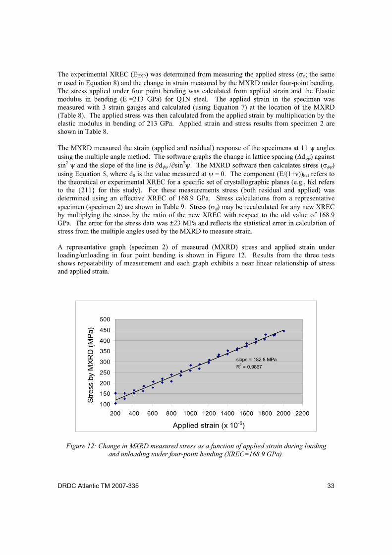
DRDC Atlantic TM 2007-335 33
The experimental XREC (EEXP) was determined from measuring the applied stress ( ; the same used in Equation 8) and the change in strain measured by the MXRD under four-point bending.
The stress applied under four point bending was calculated from applied strain and the Elastic modulus in bending (E =213 GPa) for Q1N steel. The applied strain in the specimen was measured with 3 strain gauges and calculated (using Equation 7) at the location of the MXRD (Table 8). The applied stress was then calculated from the applied strain by multiplication by the elastic modulus in bending of 213 GPa. Applied strain and stress results from specimen 2 are shown in Table 8.
The MXRD measured the strain (applied and residual) response of the specimens at 11 angles using the multiple angle method. The software graphs the change in lattice spacing ( d ) against sin2 and the slope of the line is d sin2 . The MXRD software then calculates stress ( ) using Equation 5, where d0 is the value measured at . The component (E/(1+ ))hkl refers to the theoretical or experimental XREC for a specific set of crystallographic planes (e.g., hkl refers to the {211} for this study). For these measurements stress (both residual and applied) was determined using an effective XREC of 168.9 GPa. Stress calculations from a representative specimen (specimen 2) are shown in Table 9. Stress ( ) may be recalculated for any new XREC by multiplying the stress by the ratio of the new XREC with respect to the old value of 168.9 GPa. The error for the stress data was ±23 MPa and reflects the statistical error in calculation of stress from the multiple angles used by the MXRD to measure strain.
A representative graph (specimen 2) of measured (MXRD) stress and applied strain under loading/unloading in four point bending is shown in Figure 12. Results from the three tests shows repeatability of measurement and each graph exhibits a near linear relationship of stress and applied strain.
100
150
200
250
300
350
400
450
500
200 400 600 800 1000 1200 1400 1600 1800 2000 2200
Applied strain (x 10-6)
Str
ess
by
MX
RD
(M
Pa)
slope = 182.8 MPa
R2 = 0.9867
Figure 12: Change in MXRD measured stress as a function of applied strain during loading
and unloading under four-point bending (XREC=168.9 GPa).
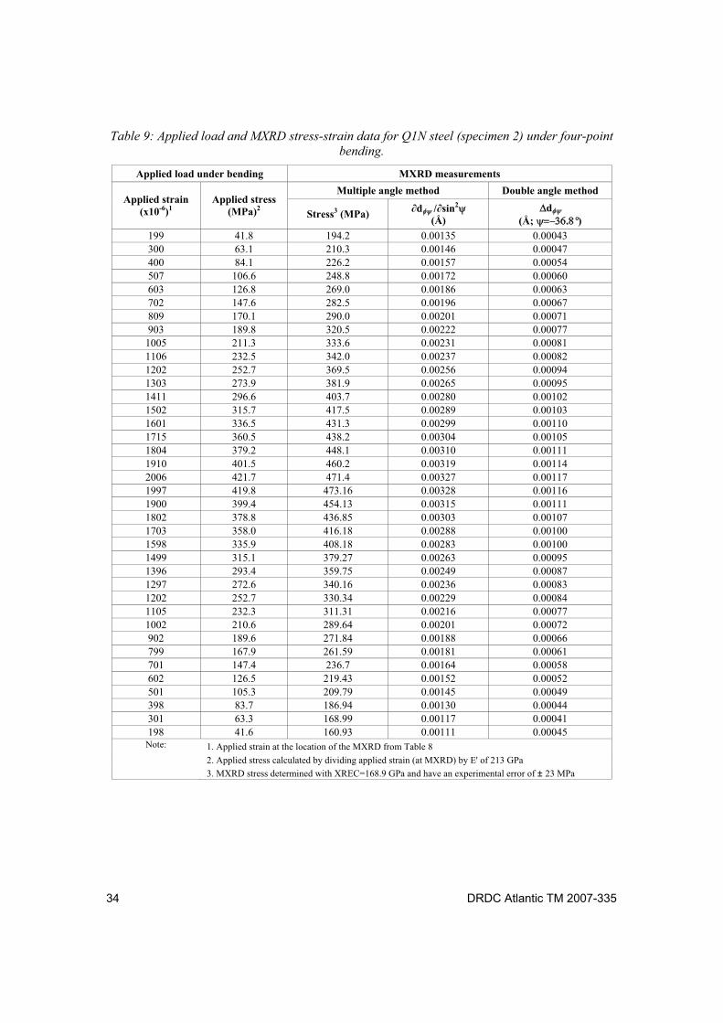
34 DRDC Atlantic TM 2007-335
Table 9: Applied load and MXRD stress-strain data for Q1N steel (specimen 2) under four-point
bending.
Applied load under bending MXRD measurements
Multiple angle method Double angle method Applied strain
(x10-6)1 Applied stress
(MPa)2 Stress3 (MPa) d / sin2
(Å) d
(Å; °)
199 41.8 194.2 0.00135 0.00043 300 63.1 210.3 0.00146 0.00047 400 84.1 226.2 0.00157 0.00054 507 106.6 248.8 0.00172 0.00060 603 126.8 269.0 0.00186 0.00063 702 147.6 282.5 0.00196 0.00067 809 170.1 290.0 0.00201 0.00071 903 189.8 320.5 0.00222 0.00077 1005 211.3 333.6 0.00231 0.00081 1106 232.5 342.0 0.00237 0.00082 1202 252.7 369.5 0.00256 0.00094 1303 273.9 381.9 0.00265 0.00095 1411 296.6 403.7 0.00280 0.00102 1502 315.7 417.5 0.00289 0.00103 1601 336.5 431.3 0.00299 0.00110 1715 360.5 438.2 0.00304 0.00105 1804 379.2 448.1 0.00310 0.00111 1910 401.5 460.2 0.00319 0.00114 2006 421.7 471.4 0.00327 0.00117 1997 419.8 473.16 0.00328 0.00116 1900 399.4 454.13 0.00315 0.00111 1802 378.8 436.85 0.00303 0.00107 1703 358.0 416.18 0.00288 0.00100 1598 335.9 408.18 0.00283 0.00100 1499 315.1 379.27 0.00263 0.00095 1396 293.4 359.75 0.00249 0.00087 1297 272.6 340.16 0.00236 0.00083 1202 252.7 330.34 0.00229 0.00084 1105 232.3 311.31 0.00216 0.00077 1002 210.6 289.64 0.00201 0.00072 902 189.6 271.84 0.00188 0.00066 799 167.9 261.59 0.00181 0.00061 701 147.4 236.7 0.00164 0.00058 602 126.5 219.43 0.00152 0.00052 501 105.3 209.79 0.00145 0.00049 398 83.7 186.94 0.00130 0.00044 301 63.3 168.99 0.00117 0.00041 198 41.6 160.93 0.00111 0.00045
Note: 1. Applied strain at the location of the MXRD from Table 8
2. Applied stress calculated by dividing applied strain (at MXRD) by E' of 213 GPa
3. MXRD stress determined with XREC=168.9 GPa and have an experimental error of ± 23 MPa
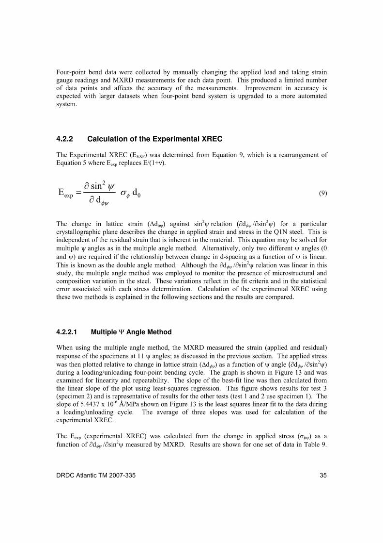
DRDC Atlantic TM 2007-335 35
Four-point bend data were collected by manually changing the applied load and taking strain gauge readings and MXRD measurements for each data point. This produced a limited number of data points and affects the accuracy of the measurements. Improvement in accuracy is expected with larger datasets when four-point bend system is upgraded to a more automated system.
4.2.2 Calculation of the Experimental XREC
The Experimental XREC (EEXP) was determined from Equation 9, which is a rearrangement of Equation 5 where Eexp replaces E/(1+ ).
0
2
exp dd
sinE (9)
The change in lattice strain ( d ) against sin2 relation ( d sin2 for a particular crystallographic plane describes the change in applied strain and stress in the Q1N steel. This is independent of the residual strain that is inherent in the material. This equation may be solved for multiple angles as in the multiple angle method. Alternatively, only two different angles (0 and ) are required if the relationship between change in d-spacing as a function of is linear. This is known as the double angle method. Although the d sin2 relation was linear in this study, the multiple angle method was employed to monitor the presence of microstructural and composition variation in the steel. These variations reflect in the fit criteria and in the statistical error associated with each stress determination. Calculation of the experimental XREC using these two methods is explained in the following sections and the results are compared.
4.2.2.1 Multiple Angle Method
When using the multiple angle method, the MXRD measured the strain (applied and residual) response of the specimens at 11 angles; as discussed in the previous section. The applied stress was then plotted relative to change in lattice strain ( d ) as a function of angle ( d sin2 during a loading/unloading four-point bending cycle. The graph is shown in Figure 13 and was examined for linearity and repeatability. The slope of the best-fit line was then calculated from the linear slope of the plot using least-squares regression. This figure shows results for test 3 (specimen 2) and is representative of results for the other tests (test 1 and 2 use specimen 1). The slope of 5.4437 x 10⁻⁶ Å/MPa shown on Figure 13 is the least squares linear fit to the data during a loading/unloading cycle. The average of three slopes was used for calculation of the experimental XREC.
The Eexp (experimental XREC) was calculated from the change in applied stress ( ) as a function of d sin2 measured by MXRD. Results are shown for one set of data in Table 9.
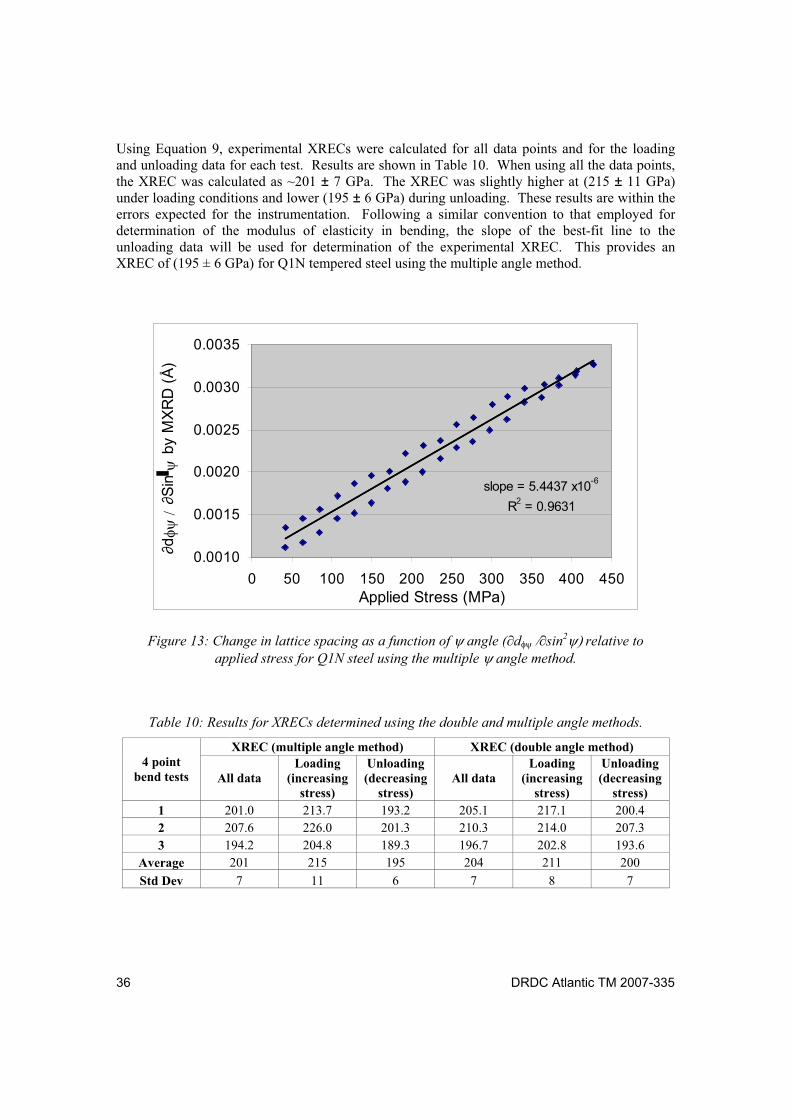
36 DRDC Atlantic TM 2007-335
Using Equation 9, experimental XRECs were calculated for all data points and for the loading and unloading data for each test. Results are shown in Table 10. When using all the data points, the XREC was calculated as ~201 ± 7 GPa. The XREC was slightly higher at (215 ± 11 GPa) under loading conditions and lower (195 ± 6 GPa) during unloading. These results are within the errors expected for the instrumentation. Following a similar convention to that employed for determination of the modulus of elasticity in bending, the slope of the best-fit line to the unloading data will be used for determination of the experimental XREC. This provides an XREC of (195 ± 6 GPa) for Q1N tempered steel using the multiple angle method.
slope = 5.4437 x10⁻⁶
R2 = 0.9631
0.0010
0.0015
0.0020
0.0025
0.0030
0.0035
0 50 100 150 200 250 300 350 400 450Applied Stress (MPa)
dS
in b
y M
XR
D (
Å)
Figure 13: Change in lattice spacing as a function of angle ( d sin2 relative to
applied stress for Q1N steel using the multiple angle method.
Table 10: Results for XRECs determined using the double and multiple angle methods.
XREC (multiple angle method) XREC (double angle method) 4 point
bend tests All data Loading
(increasing stress)
Unloading (decreasing
stress) All data
Loading (increasing
stress)
Unloading (decreasing
stress)
1 201.0 213.7 193.2 205.1 217.1 200.4
2 207.6 226.0 201.3 210.3 214.0 207.3
3 194.2 204.8 189.3 196.7 202.8 193.6
Average 201 215 195 204 211 200
Std Dev 7 11 6 7 8 7
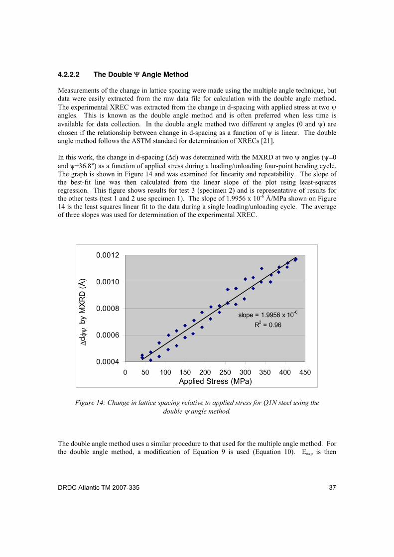
DRDC Atlantic TM 2007-335 37
4.2.2.2 The Double Angle Method
Measurements of the change in lattice spacing were made using the multiple angle technique, but data were easily extracted from the raw data file for calculation with the double angle method. The experimental XREC was extracted from the change in d-spacing with applied stress at two angles. This is known as the double angle method and is often preferred when less time is available for data collection. In the double angle method two different angles (0 and ) are chosen if the relationship between change in d-spacing as a function of is linear. The double angle method follows the ASTM standard for determination of XRECs [21].
In this work, the change in d-spacing ( d) was determined with the MXRD at two angles ( and °) as a function of applied stress during a loading/unloading four-point bending cycle. The graph is shown in Figure 14 and was examined for linearity and repeatability. The slope of the best-fit line was then calculated from the linear slope of the plot using least-squares regression. This figure shows results for test 3 (specimen 2) and is representative of results for the other tests (test 1 and 2 use specimen 1). The slope of 1.9956 x 10⁻⁶ Å/MPa shown on Figure 14 is the least squares linear fit to the data during a single loading/unloading cycle. The average of three slopes was used for determination of the experimental XREC.
slope = 1.9956 x 10⁻⁶
R2 = 0.96
0.0004
0.0006
0.0008
0.0010
0.0012
0 50 100 150 200 250 300 350 400 450Applied Stress (MPa)
d b
y M
XR
D (
Å)
Figure 14: Change in lattice spacing relative to applied stress for Q1N steel using the
double angle method.
The double angle method uses a similar procedure to that used for the multiple angle method. For the double angle method, a modification of Equation 9 is used (Equation 10). Eexp is then
38 DRDC Atlantic TM 2007-335
calculated from the change in stress as a function of change in lattice spacing ( d for a specific angle ° and d0 (at ), where d / is the slope determined from the graph of change in lattice spacing as a function of change in stress. Figure 14 shows a graph of the change in lattice spacing as a function of change in stress for specimen 2; the slope during loading/unloading is indicated.
02
exp dsind
E (10)
Experimental XRECs were calculated for all data points and for the loading and unloading data for each test using Equation 10. Results are shown in Table 10. When using all the data points, the XREC was calculated as ~204 ± 7 GPa. The XREC was slightly higher at (211 ± 8 GPa) under loading conditions and slightly lower (200 ± 7 GPa) during unloading. These results are consistent and within the errors expected for the instrumentation. Following a similar convention to that employed for determination of the modulus of elasticity in bending, the slope of the best-fit line to the unloading data will be used for determination of the experimental XREC. This provides an XREC of (200 ± 7 GPa) for Q1N tempered steel using the double angle method.
4.2.3 Experimental XREC of Q1N Steel
The experimental XREC determined by the double angle method was 200 ± 7 GPa for Q1N steel. This value was similar to the XREC of 195 ± 6 GPa that was determined with the multiple angle method. The double angle method follows the ASTM standard for determination of the experimental XREC [21]. The multiple angle method is similar to the double angle method except it employs multiple angles (in this case 11) instead of 2. It is often the method of choice due to the improved statistical error and its sensitivity to factors (microstructural, compositional, etc.) that often produce localized variation stress in steel. Given this the experimental XREC of (195 ± 7 GPa) was expected to be more representative and will be employed for future residual stress analysis on tempered Q1N steel with the portable MXRD.
4.3 Discussion
4.3.1 Reliability of Results
For the most part, MXRD methods are sensitive to the experimental procedure, operator bias and microstructure of the material to be measured. In particular, the effects of specimen preparation methods, microstructure (composition, number and structure of phases, and thermomechanical treatment), and methods used to calibrate the MXRD instrumentation, determine the elastic modulus and calculate the XREC play an important role in determining the precision and accuracy of each study.
DRDC Atlantic TM 2007-335 39
Specimen preparation and adherence to ASTM standard for specimen preparation was found to play a role in the accuracy of this method. A specimen was prepared according to two methods to investigate the effects of surface preparation on experimental XREC determination. For method 1, an as-received (prepared by electrical discharge machining) specimen underwent localized polishing at the strain gauge locations and at the location of MXRD measurements. For method 2, the entire surface of the same specimen underwent grinding; in accordance to ASTM standards [21]. The stress (measured by the MXRD) strain (from strain gauges) relationship was then determined under four-point bending and the results were compared. The statistical error in stress value (and for the XREC) for the specimen that underwent localized polishing (method 1) was ~20 (± 5) GPa, while the error for the specimen where the entire surface underwent grinding (method 2) was ~9 (± 1) GPa. This difference shows an increased uncertainty associated with the stress values determined for the specimen prepared by method 1.
This uncertainty in residual stress values became more obvious from the graphs of stress versus strain. The best fit lines to the stress-strain average varied in slope by nearly 20% for the two methods. This most likely represented scatter in data points that was apparent in the stress strain data collected after the initial preparation method (localized polishing). Although, stress-strain data were not collected below 200 microstrain to avoid surface effects, this deviation from linearity in the stress-strain graph may suggest the presence of inhomogenous non-linear strain at the depth of X-ray penetration into the specimens. The improved linearity of stress-strain data for specimens prepared following ASTM standards, i.e., surface grinding, shows this to be the better method for surface preparation for four-point bending experiments; possibly due to removal of a layer damaged by the electrical discharge machine. This method was used to prepare specimens for four-point bend testing.
The most significant errors were associated with the determination of the modulus of elasticity. The elastic modulus in bending was calculated using Equation 8 that is particularly sensitive to specimen thickness. Although a change in roller distance or specimen width by 0.1 mm produces a variation in elastic constant of less than 1 GPa, a similar variation in specimen thickness (0.1 mm) can produce a difference of ~ 14 GPa. In addition, initially, the elastic modulus in bending was determined from an insufficient number of measurements due to manual collection of stress and strain data that not only introduced operator bias into the results but produced a limited number of data points. This, when combined with inaccurate measurement of specimen size, produced an elastic modulus in bending of 187 GPa. This value was compared to the elastic modulus in tension of 208 GPa that was similar to literature estimates. The large discrepancy was unexpected and required refining of measurement techniques. This included careful measurement of specimen thickness, an increase in the number of data points (by a factor of 100x) with the automated (as opposed to manual) collection of data and the use of displacement control (as opposed to load control). This produced a better linear slope of strain with applied stress and a more consistent (over six measurements) value of 213 GPa for the elastic modulus in bending.
In addition, while every effort was made to ensure the accuracy of four-point bend measurements with the XRD, the strain and stress data were accumulated manually. This may have introduced operator bias into the measurements, while the limited number of data points may lead to inaccuracies in determination of the slope of stress versus strain. This is expected to be overcome in the future when the four-point bend system is upgraded to an automated system that permits will allow for the collection of more data points.
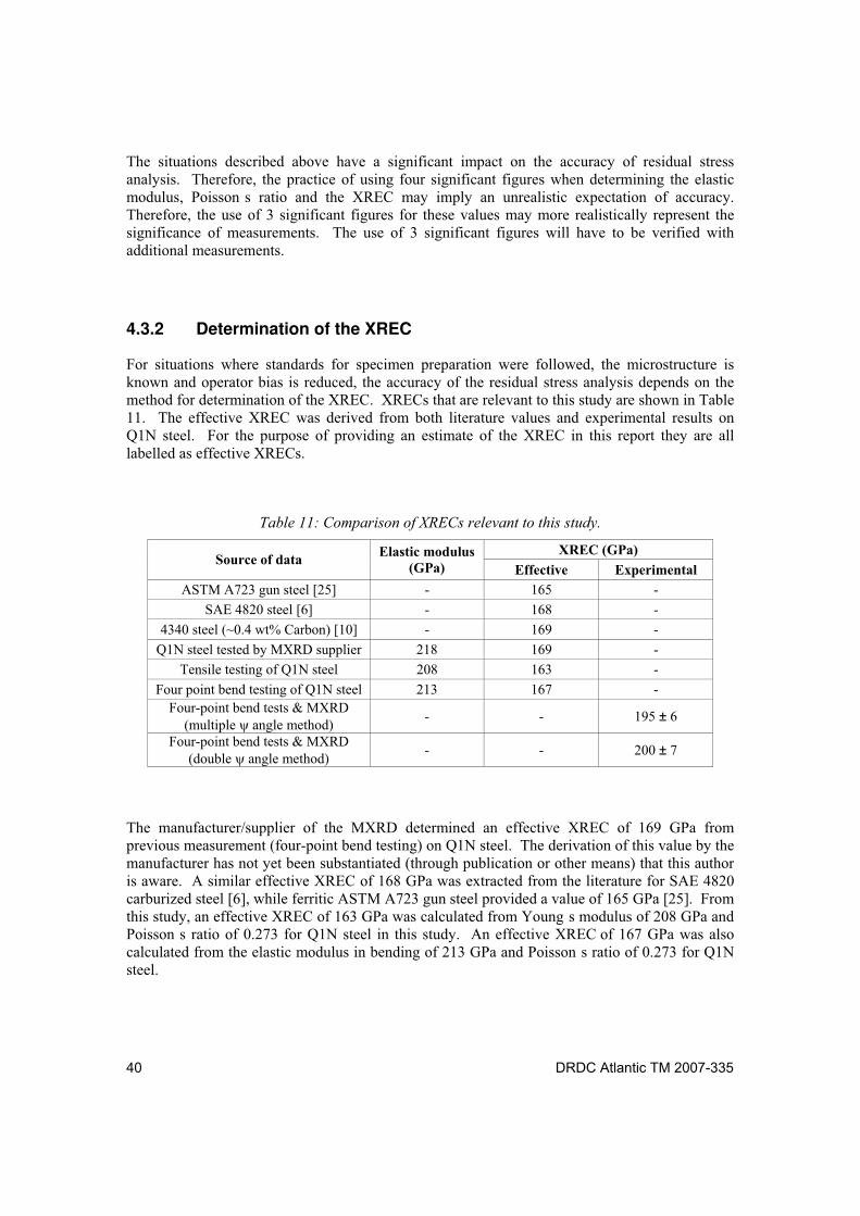
40 DRDC Atlantic TM 2007-335
The situations described above have a significant impact on the accuracy of residual stress analysis. Therefore, the practice of using four significant figures when determining the elastic modulus, Poisson s ratio and the XREC may imply an unrealistic expectation of accuracy. Therefore, the use of 3 significant figures for these values may more realistically represent the significance of measurements. The use of 3 significant figures will have to be verified with additional measurements.
4.3.2 Determination of the XREC
For situations where standards for specimen preparation were followed, the microstructure is known and operator bias is reduced, the accuracy of the residual stress analysis depends on the method for determination of the XREC. XRECs that are relevant to this study are shown in Table 11. The effective XREC was derived from both literature values and experimental results on Q1N steel. For the purpose of providing an estimate of the XREC in this report they are all labelled as effective XRECs.
Table 11: Comparison of XRECs relevant to this study.
XREC (GPa) Source of data
Elastic modulus (GPa) Effective Experimental
ASTM A723 gun steel [25] - 165 -
SAE 4820 steel [6] - 168 -
4340 steel (~0.4 wt% Carbon) [10] - 169 -
Q1N steel tested by MXRD supplier 218 169 -
Tensile testing of Q1N steel 208 163 -
Four point bend testing of Q1N steel 213 167 - Four-point bend tests & MXRD
(multiple angle method) - - 195 ± 6
Four-point bend tests & MXRD (double angle method)
- - 200 ± 7
The manufacturer/supplier of the MXRD determined an effective XREC of 169 GPa from previous measurement (four-point bend testing) on Q1N steel. The derivation of this value by the manufacturer has not yet been substantiated (through publication or other means) that this author is aware. A similar effective XREC of 168 GPa was extracted from the literature for SAE 4820 carburized steel [6], while ferritic ASTM A723 gun steel provided a value of 165 GPa [25]. From this study, an effective XREC of 163 GPa was calculated from Young s modulus of 208 GPa and Poisson s ratio of 0.273 for Q1N steel in this study. An effective XREC of 167 GPa was also calculated from the elastic modulus in bending of 213 GPa and Poisson s ratio of 0.273 for Q1N steel.
DRDC Atlantic TM 2007-335 41
The effective XRECs from the MXRD supplier (169 GPa), literature (168 GPa and 165 GPa), tensile testing (163 GPa) and four-point bend tests (167 GPa) were found to be similar (~4%) for comparable (similar composition) steel specimens. The effective XRECs determined from the literature do not reflect the microstructural differences in steels. A more reliable value had been expected from experimental measurement; especially due to the sensitivity of Poisson s ratio to these variations. The literature values were instead found to be consistent with the results determined from calculation of measured bulk elastic properties (163 GPa for tensile testing and 167 GPa from bend tests) in this study.
The experimental XREC was determined for the {211} crystallographic planes of bcc Fe (using Cr K radiation) using the MXRD for measurement of strain under four-point bending. This is believed to more accurately represent the material under investigation [4-10,12] for several reasons. MXRD four-point bend tests are more sensitive to composition and microstructural features (grain interactions, texture, etc.) and localized variation in elastic modulus. The experimental MXRD four-point bend tests more accurately reflects the elastic stress-strain behaviour for the {211} planes that was employed for determination of residual stress in Q1N steel.
Two methods were used to determine the experimental XREC from the strain measured by the MXRD as a function of applied stress during loading/unloading under four-point bending. The double angle method is the standard technique for determination of the experimental XREC [21]. With this method, the experimental XREC was determined from the change in stress as a function of change in lattice spacing ( d for two angles ( and °). The double angle method provided an XREC of 200 ±7 GPa. The multiple angle method is similar to the double angle method except that it employs multiple angles (in this case 11). In the multiple
angle method, the change in lattice strain at multiple angles ( d sin2 was determined relative to the applied stress. The Eexp was then calculated as 195 ±6 GPa. The multiple angle method is expected to provide improved statistical error and improved accuracy of residual stress values.
Results for the experimental XREC determined using the double angle technique (200 ±7 GPa) and the multiple angle technique (195 ±6 GPa) were similar. Therefore, either technique would be acceptable for residual stress analysis on Q1N steel. The genuine worth of the multiple angle technique lies in its use to monitor microstructural effects (texture, microstrain) that often manifest as deviation from linearity in the change in d-spacing versus sin2 plot or in the statistical error. Microstructural effects were not identified during the course of this study and are not believed to have had a significant effect on these measurements. Future studies will also employ the multiple angle technique to monitor microstructural effects.
The value for the effective XREC (169 GPa, from the MXRD manufacturer) used for the investigation on Q1N steel [1] and initially used during this study is quite different from the experimental XREC (195 ±6 GPa) determined in this study. This difference between the effective XREC (derived from bulk property measurement under four-point bending) and the experimental XREC (determined for the {211} crystallographic planes) of nearly 15 % is not without precedence in the literature. A similar study on carburized AISI 4820 steel showed a smaller difference in value of ~10 % [24], while the study by Bahadur et al. [26] exhibited a similar difference of ~20%. Bahadur et al. [26] studied the effect of thermomechanical treatment on the XREC of HSLA-100 steel. The variation in XREC was most likely due to microstructural
42 DRDC Atlantic TM 2007-335
differences that were not discussed. In that study, the effective XREC of 153 GPa was determined from tensile test experiments (prior to any thermomechanical treatment). The experimental XREC was determined for the {211} crystallographic planes of bcc Fe, similar to this study. An experimental XREC of 186 GPa was determined for samples that had undergone thermomechanical treatment (austenitization at 1100 °C for 60 min and water quenching) [26]. Although further thermomechanical processing had produced even larger variation in XREC values (by as much as 75%), the difference between the effective XREC (153 GPa) and the experimental XREC (186 GPa) for the austenitized specimen was over 20%. This difference is comparable to results from this study. Therefore, the difference between the effective and experimental XRECs of 15% found in this study appears reasonable.
4.3.3 Procedure for Future Residual Stress Analysis
A procedure for calibration of the MXRD for residual stress investigations on tempered Q1N steel (and relevant to other materials) is proposed. The MXRD will be calibrated with respect to known standards including a zero stress powder (Fe for steels) and at least two standards of known residual stress (determined through alternate means, ex. neutron diffraction). A literature review will be conducted to determine an effective XREC and investigate the effect of microstructure and thermomechanical processing on the XREC for the material investigated. A more accurate XREC value will be determined through calculation of the XREC from the modulus of elasticity in bending and Poisson s ratio on a representative specimen. These results will then be used to calculate the experimental XREC from strain data collected with the MXRD, using the multiple angle method, and four-point bend testing. Although the MXRD technique is a non-destructive, improved accuracy requires extraction of specimens for measurement of the elastic modulus and the XREC.
The difference in effective (both literature and derived from bulk properties) and experimental XRECs was due to the sensitivity of the XREC to variation in composition and microstructure of the steels used in the different studies. While the experimentally-derived values are believed to be more representative of the Q1N pressure hull steel, the effective XREC does provide an estimate of the XREC that is required to begin residual stress analysis. This is particularly useful when time constraints do not allow for experimental derivation of the XREC; as in a previous study on HMCS VICTORIA [1].
DRDC Atlantic TM 2007-335 43
5 Conclusions
This study was conducted to assess the portable MXRD for accurate determination of residual stress of tempered Q1N steels, such as those found on the pressure hull of VICTORIA Class submarines. At the onset, the primary focus of this study was to assess the potential sources of error associated with residual stress analysis with the MXRD. This was conducted by first reducing the errors associated with the MXRD instrument in order to focus on potential errors associated with determination of the XREC used for calculation of residual stress. This included assessment of various techniques for determination of the effective and experimental XREC as well as a proposed standard method for future analysis. Careful attention was given to understanding the fundamental science behind residual stress analysis and the limits of established standard procedures (eg. ASTM [21]) for determination of the XREC.
The accuracy and precision of residual stress analysis depends on the instrumental conditions employed for measurement of strain and on the XREC used to calculate stress from strain values. The former was discussed in terms of experimental methods and procedures required to ensure accurate measurement of strain on Q1N steel specimens. In particular, the importance of calibration of the MXRD and experimental measurement of the XREC [for the particular set of crystallographic planes (the {211} planes of bcc Fe) used to determine residual stress] on the material to be investigated were discussed. Besides inaccurate effective XREC, deviation from standard practices, instrument errors and operator biases appear to play an important role in the accuracy of residual stress analysis. These errors may become significant unless proper attention to detail is observed. More testing to determine a better estimate of precision and accuracy will be forthcoming.
In the absence of microstructural effects and instrumental alignment issues the accuracy of residual stress analysis was believed to be dependent on the derivation of the XREC employed. Several techniques were assessed for derivation of an effective (approximate) XREC for Q1N steel. Results were found to be similar for XRECs determined by the MXRD supplier (169 GPa), from literature values for similar steel (168 and 165 GPa), tensile (164 GPa) and four-point bend (167 GPa) testing.
The specimen of tempered Q1N steel from the pressure hull of HMCS VICTORIA had an elastic modulus (in bending) of 213 GPa. The experimental XREC derived using the double angle method was determined to be 200 ±7 GPa (for the {211} crystallographic planes of bcc Fe) for the Q1N steel. This result is similar to the value determined with the multiple angle method (195 ±6 GPa). The difference of 15% between the effective XREC (from tensile testing) and the experimental XREC is comparable to similar studies on other steels found in the open literature.
Although results between the double and multiple angle methods were found to be similar for this Q1N steel, this may not be necessarily true for other materials where compositional and microstructural features (grain interactions, texture, etc.) are more pronounced. Therefore, the multiple angle technique is the preferred method due to the improved statistics and the sensitivity of the multiple angle technique to microstructural effects. A procedure for calibration of the MXRD for residual stress investigations on Q1N steel (and relevant to other materials) has been proposed.
44 DRDC Atlantic TM 2007-335
The XREC value of 195 ±6 GPa is believed to more accurately represent the elastic properties of the {211} crystallographic planes of bcc Fe required for residual stress analysis of tempered Q1N steel. This value will be used to recalculate baseline residual stress values determined during the previous investigation of the pressure hull of HMCS VICTORIA and will be employed during upcoming residual stress investigations on Q1N pressure hull steel. The magnitude of the error associated with the XREC above represents the error related to variation in measurement and variation in 2 specimens over 3 datasets. A more accurate representation of the error for the XREC has yet to be determined.
DRDC Atlantic TM 2007-335 45
6 Future Work
More four-point bend testing on Q1N steel is planned when the four-point bend apparatus is upgraded to allow automated acquisition of stress strain data. This is expected to reduce operator bias and improve accuracy of measurements. In addition, improvement to four-point bend apparatus may include a sharper contact between the specimen and the bending apparatus and a means to measure deflection. Deflection of the specimen with incremental loading will be measured in the future through recent upgrades that include an automated positioning system. In an effort to improve the accuracy, residual stress calibrations will employ materials that have been accurately measured using other techniques such as neutron diffraction. Neutron diffraction residual stress analysis on Q1N pressure hull steel is currently under investigation by personnel at DRDC Atlantic.
A follow-on study will look at the influence of microstructural effects (including welding/repair procedures) on material properties (ex., elastic constant), the XREC and residual stress distribution in Q1N steel. This will provide valuable insight into proper use of the method for determination of stress and provide guidelines for how corrective procedures (that influence residual stress) may be employed for stress management/manipulation to mitigate high stress values.
Residual stress was determined on the starboard pressure hull of HMCS VICTORIA in the vicinity of the area where a pressure hull plate was removed [1]. A comprehensive investigation of residual stress in this region was conducted in January 2008, after fit-up and welding of the new insert plate. The results of which have been influenced by the XREC determined in this study. Analysis and documentation of this investigation, once completed, will be beneficial in assessing the implication of the insert plate welding procedure and provide valuable insight for future weld repair procedures.
The MXRD will be used for baseline residual stress measurement on the diesel exhaust hull and back-up valves (DEHBUV) on HMCS WINDSOR. This will be used to assess long term stress re-distribution within the submarine pressure hull due to high temperature surface environment.
It is expected that the MXRD will be employed to conduct a residual stress survey of cladded regions of the pressure hull of HMCS CHICOUTIMI to ascertain the effect of weld cladding procedures on the distribution of residual stress. This will provide insight into the accepted practice of weld clad repairing corrosion and pitting damage on the exterior surface of submarine pressure hulls to restore thickness and circularity to original specifications. A background study will delve into modification of residual stress distribution during preparation and cladding of sections of HY80 steel plate.
46 DRDC Atlantic TM 2007-335
References .....
[1] S.P. Farrell L.W. MacGregor, C.J. Bayley and J.F. Porter, Assessment of the Residual
Stress Proximal to the Dent Repair Area of HMCS VICTORIA: Prior to Accommodation
and Welding of the Insert Plate, Defence R&D Canada Atlantic Technical Memorandum, DRDC Atlantic TM 2006-275, December 2006).
[2] J. Lu, Comparative Study of Different Techniques in Handbook of Measurement of Residual Stresses, Ed. By J. Lu, Society for Experimental Mechanics Inc., The Fairmont Press Inc., Lilburn GA, 1996, pp. 225-231.
[3] P.J. Withers and H.K.D.H. Bhadeshia, Overview: Residual Stress Part 1 Measurement Techniques , Materials Sciences and Technology, 17, 2001, pp 355-365.
[4] M.E. Brauss, G.V. Gorveatte and J.F. Porter, Development of a Miniature X-Ray Diffraction Based Stress Analysis System Suitable for Use on Marine Structures , Proceedings of SPIE s Nondestructive Evaluation of Materials and Composites, Scottsdale, Arizona, December 1996, pp 307-317.
[5] M.R. James and J.B. Cohen, The Measurement of Residual Stresses by X-Ray Diffraction Techniques , in Treatise on Materials Science and Technology 19A, 1980, pp 1-62.
[6] B.D. Cullity, Elements of X-Ray Diffraction , 2nd ed., Addison Wesley Publishing Co. Inc., 1978.
[7] V. Huak, Problems of the X-Ray Stress Analysis (RSA) and Their Solutions in Residual Stresses: Measurement, Calculation, Evaluation, Ed. by V. Hauk, H. Hougardy, and E. Macherauch, DGM Informationsgesellschaft Oberursel, 1991, pp. 3-20.
[8] M. Belassel, Residual stress analyzer: Theory of operation manual, Beta Version , Proto Manufacturing Ltd. Instrument Manual, July 2001, p 120
[9] M. François, F. Convert, J. Lu, J.M. Sprauel, J.L. Lebrun, N. Ji, C.F. Déhan, R.W. Hendricks and M.R. James, X-Ray Diffraction Method in Handbook of Measurement of Residual Stresses, Ed. By J. Lu, Society for Experimental Mechanics Inc., The Fairmont Press Inc., Lilburn GA, 1996, pp. 71-131.
[10] P.S. Prevéy, X-Ray Diffraction Residual Stress Techniques Metals Handbook. 10. Metals Park: American Society for Metals, 1986, pp. 380-392.
[11] M. R. James and J. Lu, Introduction, in Handbook of Measurement of Residual Stresses , Ed. By J. Lu, Society for Experimental Mechanics, The Fairmont Press, Lilburn, GA, 1996, pp. 1-4.
DRDC Atlantic TM 2007-335 47
[12] J.A. Pineault, M. Belassel and M.E. Brauss, X-Ray Diffraction Residual Stress Measurement in Failure Analysis in ASM Handbook, Vol. 11, Failure Analysis and Prevention, Ed. by W.T. Becker and R.J. Shipley for ASM International, Materials Park, Ohio, 2007, pp. 484-497.
[13] P.J. Withers and H.K.D.H. Bhadeshia, Overview: Residual Stress Part 1 Measurement Techniques , Materials Sciences and Technology, 17, 2001, pp 355-365.
[14] C.O. Ruud, P.S. DiMascio, and J.J. Yavelak, Comparison of Three Residual-Stress Measurement Methods on a Mild Steel , Experimental Mechanics, 25, 1985, pp. 338-343.
[15] J.D. Lord, P.V. Grant, A.T. Fry and F.A. Kandil, A UK Residual Stress Intercomparison Exercise Development of Measurement Good Practice for the XRD and Hole Drilling Techniques Report from NPL Materials Centre, National Physical Laboratory, Teddington, Middlesex, UK, 2002.
[16] Standard Test Method for Determination of Retained Austenite in Steel with Nearly Random Crystallographic Orientation , E 975-95, Annual Book of ASTM Standards, Vol. 03.01, ASTM, Philadelphia, 2000, pp. 916-721.
[17] C. Bayley and T. Romans, Comparison of Pressure Hull Straightening Approaches: Mechanical and Flame Straightening , Defence R&D Canada Atlantic Technical Memorandum, DRDC Atlantic TM 2007-184, 36 pgs.
[18] Ministry of Defence Requirement for Q1(Navy) Quality Steel Part 1 Plates, Issue 2, DefStan 02-736(Part 1)/2 July 2004.
[19] C. Bayley, Stress-Strain Characterization of NQ1 Pressure Hull Material , Defence R&D Canada Atlantic Technical Note, DRDC Atlantic TN 2007-328, 14 pgs.
[20] Standard Test Methods for Tension Testing of Metallic Materials (Metric) , E 8M-00, Annual Book of ASTM Standards, Vol. 03.01, ASTM, Philadelphia, 2000, pp. 77-98.
[21] Standard Test Method for Determining the Effective Elastic Parameter for X-Ray Diffraction Measurements of Residual Stress , E 1426-98, Annual Book of ASTM Standards, Vol. 03.01, ASTM, Philadelphia, 2000, pp. 916-919.
[22] Standard Test Method for Poisson s Ratio at Room Temperature , E 132-97, Annual Book of ASTM Standards, Vol. 03.01, ASTM, Philadelphia, 2000, pp. 264-266.
[23] H.A. Kuhn, Overview of Mechanical Properties and Testing for Design in ASM Handbook, Vol. 8, Mechanical Testing and Evaluation, Ed. by H.A. Kuhn and D Medlin for ASM International, Materials Park, Ohio, 1990, pp. 49-69.
[24] Residual Stress Measurement by X-Ray Diffraction , SAE J784a, Society of Automotive Engineers (SAE) Information Report, Second Edition, Published by SAE Inc., New York, 119 pages. 1971.
48 DRDC Atlantic TM 2007-335
[25] S.L. Lee, M. Doxbeck and G.P. Capsimalis, Experimental Methods in Residual Stress Measurement using a Position-Sensitive Single-Exposure Scintillation Detection System , U.S. Army ARDEC report, Benet Laboratories SMCAR-CCB-TL (report # ARCCB-TR-94036), Sept 1994, 27 pages.
[26] A. Bahadur, B.R. Kumar and S.G. Chowdhury, Effect of Thermomechanical Treatment on X-Ray Elastic Constants and Residual Stresses in HSLA-100 Steel , Journal of Nondestructive Evaluation, Volume 22, Number 2 / June, 2003 pp. 53-62.
[27] R.H. Marion and J.B. Cohen, The Need for Experimentally Determined X-Ray Elastic Constants , Technical report of the Northwestern University of Evanston Ill Dept of Materials Science and Engineering, Aug 1976, 16 pages.
[28] "Standard Method for Verifying the Alignment of X-ray Diffraction Instrumentation for Residual Stress Measurement," E 915-96, Annual Book of ASTM Standards, Vol. 03.01, ASTM, Philadelphia, 2000, pp 809-812.
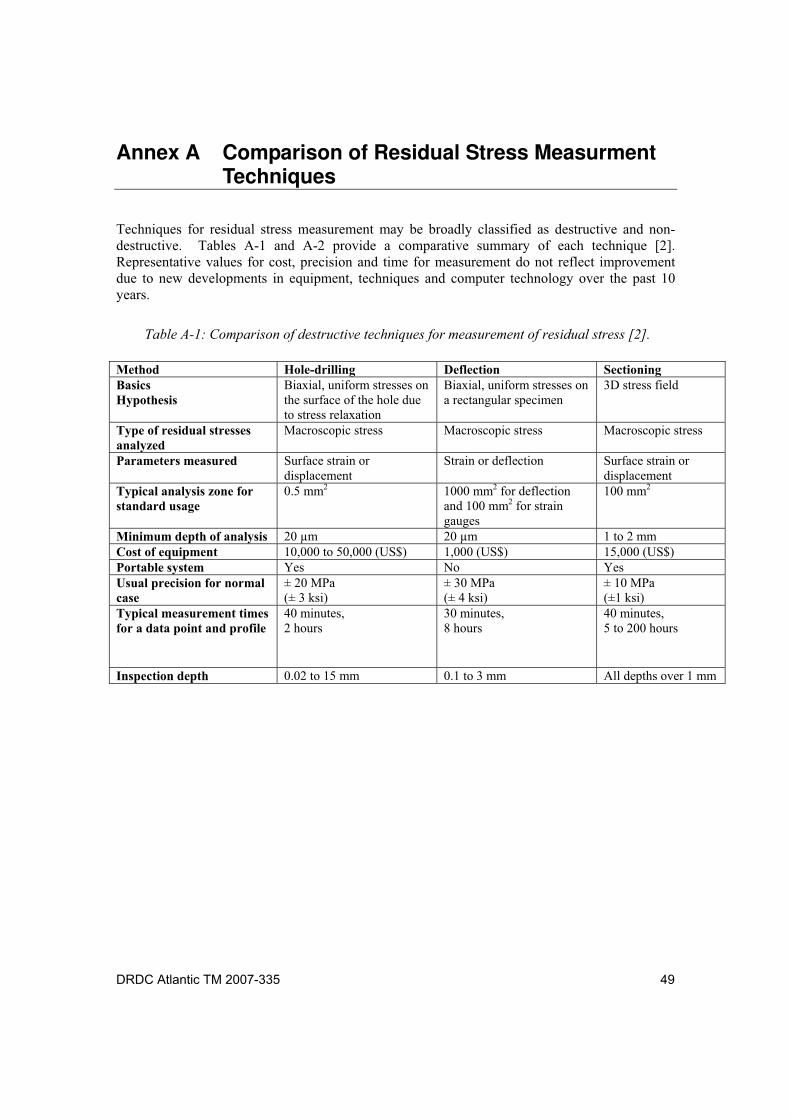
DRDC Atlantic TM 2007-335 49
Annex A Comparison of Residual Stress Measurment Techniques
Techniques for residual stress measurement may be broadly classified as destructive and non-destructive. Tables A-1 and A-2 provide a comparative summary of each technique [2]. Representative values for cost, precision and time for measurement do not reflect improvement due to new developments in equipment, techniques and computer technology over the past 10 years.
Table A-1: Comparison of destructive techniques for measurement of residual stress [2].
Method Hole-drilling Deflection Sectioning Basics Hypothesis
Biaxial, uniform stresses on the surface of the hole due to stress relaxation
Biaxial, uniform stresses on a rectangular specimen
3D stress field
Type of residual stresses analyzed
Macroscopic stress Macroscopic stress Macroscopic stress
Parameters measured Surface strain or displacement
Strain or deflection Surface strain or displacement
Typical analysis zone for standard usage
0.5 mm2 1000 mm2 for deflection and 100 mm2 for strain gauges
100 mm2
Minimum depth of analysis 20 µm 20 µm 1 to 2 mm Cost of equipment 10,000 to 50,000 (US$) 1,000 (US$) 15,000 (US$) Portable system Yes No Yes Usual precision for normal case
± 20 MPa (± 3 ksi)
± 30 MPa (± 4 ksi)
± 10 MPa (±1 ksi)
Typical measurement times for a data point and profile
40 minutes, 2 hours
30 minutes, 8 hours
40 minutes, 5 to 200 hours
Inspection depth 0.02 to 15 mm 0.1 to 3 mm All depths over 1 mm
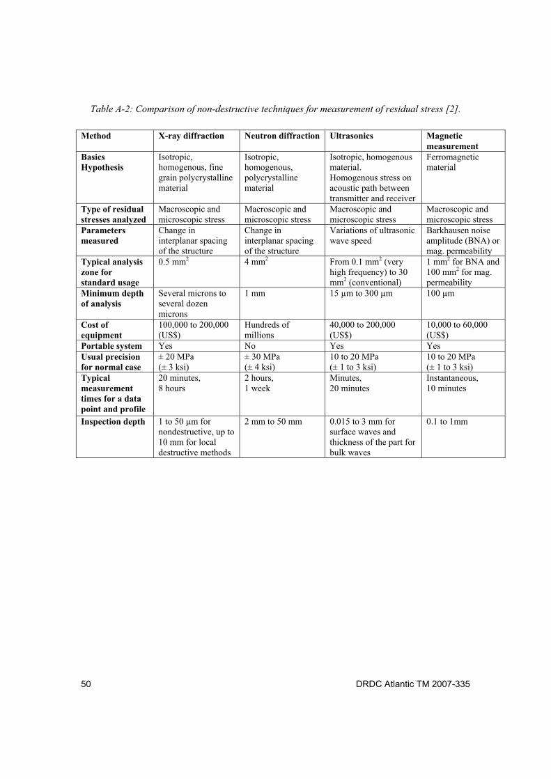
50 DRDC Atlantic TM 2007-335
Table A-2: Comparison of non-destructive techniques for measurement of residual stress [2].
Method X-ray diffraction Neutron diffraction Ultrasonics Magnetic measurement
Basics Hypothesis
Isotropic, homogenous, fine grain polycrystalline material
Isotropic, homogenous, polycrystalline material
Isotropic, homogenous material. Homogenous stress on acoustic path between transmitter and receiver
Ferromagnetic material
Type of residual stresses analyzed
Macroscopic and microscopic stress
Macroscopic and microscopic stress
Macroscopic and microscopic stress
Macroscopic and microscopic stress
Parameters measured
Change in interplanar spacing of the structure
Change in interplanar spacing of the structure
Variations of ultrasonic wave speed
Barkhausen noise amplitude (BNA) or mag. permeability
Typical analysis zone for standard usage
0.5 mm2 4 mm2 From 0.1 mm2 (very high frequency) to 30 mm2 (conventional)
1 mm2 for BNA and 100 mm2 for mag. permeability
Minimum depth of analysis
Several microns to several dozen microns
1 mm 15 µm to 300 µm 100 µm
Cost of equipment
100,000 to 200,000 (US$)
Hundreds of millions
40,000 to 200,000 (US$)
10,000 to 60,000 (US$)
Portable system Yes No Yes Yes Usual precision for normal case
± 20 MPa (± 3 ksi)
± 30 MPa (± 4 ksi)
10 to 20 MPa (± 1 to 3 ksi)
10 to 20 MPa (± 1 to 3 ksi)
Typical measurement times for a data point and profile
20 minutes, 8 hours
2 hours, 1 week
Minutes, 20 minutes
Instantaneous, 10 minutes
Inspection depth 1 to 50 µm for nondestructive, up to 10 mm for local destructive methods
2 mm to 50 mm 0.015 to 3 mm for surface waves and thickness of the part for bulk waves
0.1 to 1mm
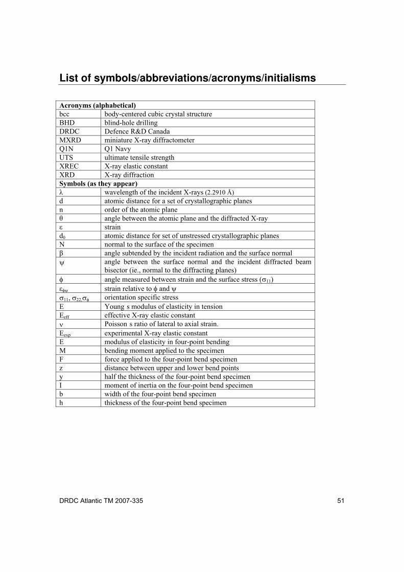
DRDC Atlantic TM 2007-335 51
List of symbols/abbreviations/acronyms/initialisms
Acronyms (alphabetical) bcc body-centered cubic crystal structureBHD blind-hole drillingDRDC Defence R&D CanadaMXRD miniature X-ray diffractometerQ1N Q1 NavyUTS ultimate tensile strength XREC X-ray elastic constant XRD X-ray diffraction Symbols (as they appear)
wavelength of the incident X-rays (2.2910 Å)
d atomic distance for a set of crystallographic planes n order of the atomic plane
angle between the atomic plane and the diffracted X-ray strain
d0 atomic distance for set of unstressed crystallographic planesN normal to the surface of the specimen
angle subtended by the incident radiation and the surface normal angle between the surface normal and the incident diffracted beam bisector (ie., normal to the diffracting planes)
angle measured between strain and the surface stress ( )strain relative to and
, orientation specific stressE Young s modulus of elasticity in tensionEeff effective X-ray elastic constant
Poisson s ratio of lateral to axial strain.Eexp experimental X-ray elastic constant E modulus of elasticity in four-point bending M bending moment applied to the specimen F force applied to the four-point bend specimen z distance between upper and lower bend points y half the thickness of the four-point bend specimenI moment of inertia on the four-point bend specimenb width of the four-point bend specimen h thickness of the four-point bend specimen

52 DRDC Atlantic TM 2007-335
This page intentionally left blank.
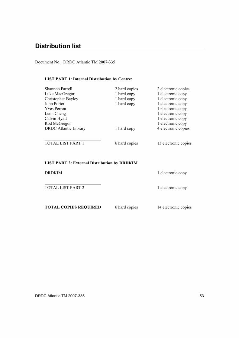
DRDC Atlantic TM 2007-335 53
Distribution list
Document No.: DRDC Atlantic TM 2007-335
LIST PART 1: Internal Distribution by Centre:
Shannon Farrell 2 hard copies 2 electronic copies Luke MacGregor 1 hard copy 1 electronic copy Christopher Bayley 1 hard copy 1 electronic copy John Porter 1 hard copy 1 electronic copy Yves Perron 1 electronic copy Leon Cheng 1 electronic copy Calvin Hyatt 1 electronic copy Rod McGregor 1 electronic copy DRDC Atlantic Library 1 hard copy 4 electronic copies TOTAL LIST PART 1 6 hard copies 13 electronic copies
LIST PART 2: External Distribution by DRDKIM
DRDKIM 1 electronic copy TOTAL LIST PART 2 1 electronic copy
TOTAL COPIES REQUIRED 6 hard copies 14 electronic copies

54 DRDC Atlantic TM 2007-335
This page intentionally left blank.
DOCUMENT CONTROL DATA (Security classification of title, body of abstract and indexing annotation must be entered when the overall document is classified)
1. ORIGINATOR (The name and address of the organization preparing the document. Organizations for whom the document was prepared, e.g. Centre sponsoring a contractor's report, or tasking agency, are entered in section 8.)
Defence R&D Canada Atlantic 9 Grove Street P.O. Box 1012 Dartmouth, Nova Scotia B2Y 3Z7
2. SECURITY CLASSIFICATION (Overall security classification of the document including special warning terms if applicable.)
UNCLASSIFIED
3. TITLE (The complete document title as indicated on the title page. Its classification should be indicated by the appropriate abbreviation (S, C or U) in parentheses after the title.)
Residual Stress Analysis of Q1N Submarine Pressure Hull Steel with the Portable Miniature X-Ray Diffractometer:
4. AUTHORS (last name, followed by initials ranks, titles, etc. not to be used)
Farrell S.P.; MacGregor L.A.
5. DATE OF PUBLICATION (Month and year of publication of document.)
May 2008
6a. NO. OF PAGES (Total containing information, including Annexes, Appendices, etc.)
72
6b. NO. OF REFS (Total cited in document.)
28
7. DESCRIPTIVE NOTES (The category of the document, e.g. technical report, technical note or memorandum. If appropriate, enter the type of report, e.g. interim, progress, summary, annual or final. Give the inclusive dates when a specific reporting period is covered.)
Technical Memorandum
8. SPONSORING ACTIVITY (The name of the department project office or laboratory sponsoring the research and development include address.)
Defence R&D Canada Atlantic 9 Grove Street P.O. Box 1012 Dartmouth, Nova Scotia B2Y 3Z7
9a. PROJECT OR GRANT NO. (If appropriate, the applicable research and development project or grant number under which the document was written. Please specify whether project or grant.)
20CM07
9b. CONTRACT NO. (If appropriate, the applicable number under which the document was written.)
10a. ORIGINATOR'S DOCUMENT NUMBER (The official document number by which the document is identified by the originating activity. This number must be unique to this document.)
DRDC Atlantic TM 2007-335
10b. OTHER DOCUMENT NO(s). (Any other numbers which may be assigned this document either by the originator or by the sponsor.)
11. DOCUMENT AVAILABILITY (Any limitations on further dissemination of the document, other than those imposed by security classification.)
Unlimited
12. DOCUMENT ANNOUNCEMENT (Any limitation to the bibliographic announcement of this document. This will normally correspond to the Document Availability (11). However, where further distribution (beyond the audience specified in (11) is possible, a wider announcement audience may be selected.))
Unlimited
13. ABSTRACT (A brief and factual summary of the document. It may also appear elsewhere in the body of the document itself. It is highly desirable that the abstract of classified documents be unclassified. Each paragraph of the abstract shall begin with an indication of the security classification of the information in the paragraph (unless the document itself is unclassified) represented as (S), (C), (R), or (U). It is not necessary to include here abstracts in both official languages unless the text is bilingual.)
Accurate depiction of residual stress state in submarine structures using X-ray diffraction requiresmicrostructural/compositional analysis and reliable equipment and methodology for analysis. This studywas conducted to assess the portable miniature X-ray diffractometer (MXRD), owned and operated byDefence R&D Canada, for accurate determination of residual stress on tempered Q1N steels such asfound on the pressure hull of VICTORIA Class submarines. In the absence of microstructural effects andinstrumental alignment issues, not identified in this study, the accuracy of residual stress analysis isbelieved to be dependent on the accuracy of techniques used for derivation of the X-ray elastic constant(XREC) required for residual stress analysis. In this report, effective XRECs were determined usingseveral methods (literature references, experimental measurement of tensile properties and four-pointbending experiments) and results were compared. Specimens of tempered Q1N steel were extracted fromthe pressure hull of HMCS VICTORIA. A modulus of elasticity of 213 GPa in bending and 208 GPa intension was determined for the tempered Q1N steel; consistent with literature values for similar steel.Effective XRECs from the MXRD supplier and open literature (specially the {211} crystallographicplanes of bcc Fe) were found to be similar to values derived from tension (163.5 GPa) and four-pointbending (167 GPa) tests.
Although effective XRECs provide a reasonable estimate, the sensitivity of the XREC to composition andmicrostructure requires a more accurate value determined from experiment. The experimental XREC wascalculated as 195 ±6 GPa (for the {211} crystallographic planes of bcc Fe) for the Q1N steel using themultiple angle method. This value was similar to the XREC derived using the double angle method(200 ±7 GPa). Although similar results were found from both methods, this may not be necessarily truefor other materials where compositional and microstructural features (grain interactions, texture, etc.) aremore pronounced. Therefore, the multiple angle technique is the preferred method due to the improvedstatistics and its sensitivity to microstructural effects. The importance of understanding the instrumentalerrors and operator bias on the accuracy of MXRD residual stress analysis is also discussed. A procedurefor calibration of the MXRD for future residual stress investigations on Q1N steel (relevant to othermaterials) has been proposed.
Pour pouvoir faire une description précise de l état de contrainte résiduelle dans les structures d un sous-marin au moyen de la diffraction X, il faut faire une analyse de la microstructure/composition, avoir del équipement fiable et une bonne méthode d analyse. La présente étude a été réalisée afin d évaluer lacapacité du diffractomètre à rayons X miniature portatif (MXRD), propriété de RDDC et exploité parRDDC, à déterminer avec précision la contrainte résiduelle d aciers revenus Q1N, comme ceux seretrouvant dans la coque de haute pression des sous-marins de la classe VICTORIA. En l absence deproblèmes d effets micro-structurels et d alignement des appareils, que nous n avons pas rencontrés lorsde la présente étude, on pense que la précision de l analyse de la contrainte résiduelle dépend de laprécision des techniques utilisées pour le calcul de la constante élastique sous rayons X (XREC) requisepour cette analyse. Dans le présent rapport, on a déterminé des XREC efficaces au moyen de plusieursméthodes (références bibliographiques, mesures expérimentales des propriétés d allongement etexpériences de déformation en quatre points), et les résultats ont été comparés. Des éprouvettes d acierrevenu Q1N ont été extraites de la coque de haute pression du NCSM VICTORIA. On a déterminé unmodule élastique de 213 GPa en déformation et de 208 GPa en tension pour l acier revenu Q1N, valeurscorrespondant à celles de la littérature pour des aciers similaires. On a trouvé que les XREC efficaces dufournisseur du MXRD et de la littérature (spécifiques au plans cristallographiques {211} du Fe cubiquecentré) étaient similaires aux valeurs calculées à partir des tests en tension (163,5 GPa) ou de déformationen quatre points (167 GPa).
Bien que les XREC efficaces fournissent une estimation raisonnable, la sensibilité de la XREC à lacomposition et à la microstructure exige la détermination expérimentale d une valeur plus précise. On acalculé que la XREC expérimentale était de 195 ±6 GPa (pour les plans cristallographiques {211} du Fecubique centré) pour l acier Q1N, au moyen de la méthode à angle multiple. Cette valeur est similaireà celle calculée au moyen de la méthode à angle double (200 ±7 GPa). Bien que des résultats similairesaient été trouvés par les deux méthodes, ceci n est pas nécessairement vrai pour d autres matériaux danslesquels les caractéristiques de composition et de microstructure (interactions des grains, texture, etc.)sont plus prononcées. La technique à angle multiple est donc la méthode préférée en raison de meilleursrésultats statistiques et de sa plus grande sensibilité aux effets microstructuraux. On discute également del importance de la compréhension des erreurs expérimentales et de l erreur systématique due à l opérateursur la précision de l analyse des contraintes résiduelles au moyen du MXRD. On propose une procédured étalonnage du MXRD pour de futures études de la contrainte résiduelle dans l acier Q1N (pertinentepour d autres matériaux).
14. KEYWORDS, DESCRIPTORS or IDENTIFIERS (Technically meaningful terms or short phrases that characterize a document and could be helpful in cataloguing the document. They should be selected so that no security classification is required. Identifiers, such as equipment model designation, trade name, military project code name, geographic location may also be included. If possible keywords should be selected from a published thesaurus, e.g. Thesaurus of Engineering and Scientific Terms (TEST) and that thesaurus identified. If it is not possible to select indexing terms which are Unclassified, the classification of each should be indicated as with the title.)
Residual stress analysis, Portable miniature X-ray diffraction, Q1N pressure hull steel, HMCS VICTORIA, X-ray elastic constant, Four-point bending, Elastic modulus

This page intentionally left blank.

This page intentionally left blank.