Research Article Simulation Analysis of the Four...
15
Research Article Simulation Analysis of the Four Configurations of Solar Desiccant Cooling System Using Evaporative Cooling in Tropical Weather in Malaysia M. M. S. Dezfouli, 1 S. Mat, 1 G. Pirasteh, 2 K. S. M. Sahari, 3 K. Sopian, 1 and M. H. Ruslan 1 1 Solar Energy Research Institute (SERI), Universiti Kebangsaan Malaysia, 43600 Bangi, Selangor, Malaysia 2 Department of Mechanical Engineering, Faculty of Engineering, University of Malaya, 50603 Kuala Lumpur, Malaysia 3 Department of Mechanical Engineering, Universiti Tenaga Nasional, Jalan IKRAM-UNITEN, 43000 Kajang, Selangor, Malaysia Correspondence should be addressed to M. M. S. Dezfouli; [email protected] Received 29 May 2013; Revised 13 November 2013; Accepted 29 November 2013; Published 2 February 2014 Academic Editor: Ismail H. Altas Copyright © 2014 M. M. S. Dezfouli et al. is is an open access article distributed under the Creative Commons Attribution License, which permits unrestricted use, distribution, and reproduction in any medium, provided the original work is properly cited. A high demand for air conditioning systems exists in hot and humid regions because of the warm climate during the year. e high energy consumption of conventional air conditioning system is the reason for our investigation of the solar desiccant cooling system as an energy-efficient cooling system. Four model configurations were considered to determine the best configuration of a solar desiccant cooling system: one-stage ventilation, one-stage recirculation, two-stage ventilation, and two-stage recirculation. ese models were stimulated for 8,760hr of operation under hot and humid weather in Malaysia. Several parameters (i.e., coefficient of performance or COP, room temperature and humidity ratio, and the solar fraction of each system) were evaluated by detecting the temperature and humidity ratio of the different points of each configuration by TRNSYS simulation. e latent and sensible loads of the test room were 0.875kW and 2.625kW, respectively. By investigating the simulation results of the four systems, the ventilation modes were found to be higher than the recirculation modes in the one- and two-stage solar desiccant cooling systems. e isothermal dehumidification COP of the two-stage ventilation was higher than that of the two-stage recirculation. Hence, the two-stage ventilation mode desiccant cooling system in a hot and humid area has higher efficiency than the other configurations. 1. Introduction Because of the high electrical consumption of conventional vapor compression systems, the solar desiccant cooling sys- tem has been considered as one of the promising alternatives to cooling air where the sensible and latent heats of air are removed separately [1]. e first desiccant cooling system was presented by Pennington in 1955 [2]. Generally, depending on the dehumidification material used, two kinds of desiccant cooling system exist: solid and liquid. Many scientists and researchers have studied both kinds of desiccant cooling using renewable energy [3]. e common materials used in the solid and liquid desiccant cooling systemwere silica gel and liquid water-lithium chloride. e desiccant cool- ing system includes three main units, namely, desiccant, heat-source, and cooling units [4]. e elements of each unit are designed depending on the weather conditions. e components of the basic cycle consist of the solid desiccant wheel (DW) as dehumidifier, evaporative cooler as the cooling unit, and the heat recovery wheel as the heater and cooler in the regeneration and process air sides, respectively. In recent years, according to the Pennington cycle, different types of solid desiccant cooling cycles have been designed in the world by different researchers. e coefficient of performance (COP) of the desiccant cooling system, regeneration temperature, mass flow rate, fresh air, and relative humidity of the supply air are the important parameters considered by the researchers. Haddad et al. [5] studied the simulation of a desiccant-evaporative cooling system for residential buildings. ey found that the use of solar energy for regeneration of the DW can provide a significant portion of the auxiliary thermal energy needed. Hindawi Publishing Corporation International Journal of Photoenergy Volume 2014, Article ID 843617, 14 pages http://dx.doi.org/10.1155/2014/843617
Transcript of Research Article Simulation Analysis of the Four...
Research ArticleSimulation Analysis of the Four Configurations of SolarDesiccant Cooling System Using Evaporative Cooling in TropicalWeather in Malaysia
M. M. S. Dezfouli,1 S. Mat,1 G. Pirasteh,2 K. S. M. Sahari,3 K. Sopian,1 and M. H. Ruslan1
1 Solar Energy Research Institute (SERI), Universiti Kebangsaan Malaysia, 43600 Bangi, Selangor, Malaysia2 Department of Mechanical Engineering, Faculty of Engineering, University of Malaya, 50603 Kuala Lumpur, Malaysia3 Department of Mechanical Engineering, Universiti Tenaga Nasional, Jalan IKRAM-UNITEN, 43000 Kajang, Selangor, Malaysia
Correspondence should be addressed to M. M. S. Dezfouli; [email protected]
Received 29 May 2013; Revised 13 November 2013; Accepted 29 November 2013; Published 2 February 2014
Academic Editor: Ismail H. Altas
Copyright © 2014 M. M. S. Dezfouli et al. This is an open access article distributed under the Creative Commons AttributionLicense, which permits unrestricted use, distribution, and reproduction in any medium, provided the original work is properlycited.
A high demand for air conditioning systems exists in hot and humid regions because of the warm climate during the year.The highenergy consumption of conventional air conditioning system is the reason for our investigation of the solar desiccant cooling systemas an energy-efficient cooling system. Four model configurations were considered to determine the best configuration of a solardesiccant cooling system: one-stage ventilation, one-stage recirculation, two-stage ventilation, and two-stage recirculation. Thesemodels were stimulated for 8,760 hr of operation under hot and humid weather in Malaysia. Several parameters (i.e., coefficientof performance or COP, room temperature and humidity ratio, and the solar fraction of each system) were evaluated by detectingthe temperature and humidity ratio of the different points of each configuration by TRNSYS simulation. The latent and sensibleloads of the test room were 0.875 kW and 2.625 kW, respectively. By investigating the simulation results of the four systems, theventilation modes were found to be higher than the recirculation modes in the one- and two-stage solar desiccant cooling systems.The isothermal dehumidification COP of the two-stage ventilation was higher than that of the two-stage recirculation. Hence, thetwo-stage ventilation mode desiccant cooling system in a hot and humid area has higher efficiency than the other configurations.
1. Introduction
Because of the high electrical consumption of conventionalvapor compression systems, the solar desiccant cooling sys-tem has been considered as one of the promising alternativesto cooling air where the sensible and latent heats of air areremoved separately [1].The first desiccant cooling systemwaspresented by Pennington in 1955 [2]. Generally, depending onthe dehumidification material used, two kinds of desiccantcooling system exist: solid and liquid. Many scientists andresearchers have studied both kinds of desiccant coolingusing renewable energy [3]. The common materials usedin the solid and liquid desiccant cooling systemwere silicagel and liquid water-lithium chloride. The desiccant cool-ing system includes three main units, namely, desiccant,heat-source, and cooling units [4]. The elements of each
unit are designed depending on the weather conditions.The components of the basic cycle consist of the soliddesiccant wheel (DW) as dehumidifier, evaporative cooleras the cooling unit, and the heat recovery wheel as theheater and cooler in the regeneration and process air sides,respectively. In recent years, according to the Penningtoncycle, different types of solid desiccant cooling cycles havebeen designed in the world by different researchers. Thecoefficient of performance (COP) of the desiccant coolingsystem, regeneration temperature, mass flow rate, fresh air,and relative humidity of the supply air are the importantparameters considered by the researchers. Haddad et al. [5]studied the simulation of a desiccant-evaporative coolingsystem for residential buildings. They found that the useof solar energy for regeneration of the DW can provide asignificant portion of the auxiliary thermal energy needed.
Hindawi Publishing CorporationInternational Journal of PhotoenergyVolume 2014, Article ID 843617, 14 pageshttp://dx.doi.org/10.1155/2014/843617
2 International Journal of Photoenergy
Fong et al. [6] designed a simulation model (TRNSYS) ofan integrated radiant cooling by absorption refrigerationand desiccant dehumidification. Salehi Dezfouli et al. [7]investigated the solar hybrid desiccant cooling system in hotand humid weather in Malaysia. They found that a solarhybrid solid desiccant cooling system provided considerableenergy savings in comparison with the conventional vaporcompression in hot and humid area.
Researchers have studied and compared the COP ofventilation and recirculation cycles. Jain et al. [8] evaluatedventilation and recirculation cycles based on weather data inIndia to determine the effectiveness of evaporative coolerson the COP of a cooling system. Boundoukan et al. [9]evaluated a comparison between ventilation and recircu-lation procedure modes; critical values were achieved forcycle component performance specifics required to yield agiven supply air temperature condition. Mehmet et al. [10]evaluated First low and second Low for COPs of ventilationand recirculation cycles. Panaras et al. [11] investigated thebehavior of the COP of the ventilation and recirculationdesiccant cooling systems in terms of the air flow rate.They found that the ventilation cycle presents a higher COP,and the required air flow rate is similar for both cycles.Sphaier et al. [12] studied the simulation of ventilation andrecirculation desiccant cooling systems to analyze the impactof cycle component characteristics on the overall systemperformance. They concluded that, although all componentscan influence the COP, the COP values of the recirculationcycle are lower than the ventilation cycle.
With regard to the increase in temperature of the processair after dehumidification and the limitation capacity ofthe dehumidification by the DW, the required regenerationtemperature is high, especially in hot and humid regions[13–16]. Many researchers have attempted to determine thebest solution for the high required regeneration temperatureproblem in one-stage desiccant cooling systems. The isother-mal dehumidification process is a great solution to solve thisproblem. The required cool process air after dehumidifica-tion and reduced regeneration temperature can be obtainedusing isothermal dehumidification technology or multistagedehumidification process. Meckler [17] proposed a two-stagesolid desiccant air conditioning system integrated with anHVAC system. A two-stage system was also introduced byHenning [18]. A novel rotary desiccant cooling cycle withisothermal dehumidification and regenerative evaporativecooling was proposed by La et al. [19]. They found that theisothermal dehumidification was relatively lower tempera-ture requirement for the heat source because the regenerationtemperature is reduced from 80∘C to approximately 60∘C.Ge et al. [20] evaluated the performance of a two-stagerotary desiccant cooling (TSRDC) system. The requiredregeneration temperature of the TSRDC system is low, andthe COP of the system is high. La et al. [21] performed atheoretical analysis of a solar-driven TSRDC system assistedby vapor compression air conditioning. They concludedthat the solar-driven two-stage desiccant cooling system isreliable and energy efficient. Li et al. [22] investigated theTSRDC/heating system driven by evacuated glass tube solarair collectors. Their experimental results indicated that the
average thermal COP in the cooling cycle was 0.97, and thecooling capacity was in the range from 16.3 kW to 25.6 kWunder hot and humid ambient conditions. Li et al. [23]carried out experimental investigation on a one-rotor two-stage desiccant cooling/heating system driven by solar aircollectors. The average thermal COP in the cooling cycle is0.95 in hot and humid climate conditions.
Given the use of ambient air in solar desiccant cooling sys-tems, the ambient conditions of each region have a significantimpact on system performance. Although various studiesand publications on the one-stage and two-stage desiccantcooling systems have been based on differentweather data, nosuch study compares one-stage and two-stage solar coolingtechnologies that have been undertaken in Malaysia. Thehigh demands of air conditioning systems because of hot andhumid weather during the year, as well as the high energyconsumption of conventional AC systems, have resulted inthe investigation of the solar desiccant cooling system as anefficient air conditioning system in Malaysia. The presentpaper presents a comparison simulation study among thefour configurations of solar desiccant cooling system in hothumid weather in Malaysia.
2. Methodology
The comparison performance between the one-stage andtwo-stage solar desiccant cooling systems under the venti-lation and recirculation modes is used as the methodologyin this study. The one-stage and two-stage desiccant coolingsystems are explained in the following sections.
2.1. Case Study Description. Four kinds of solar desiccantcooling systems were considered to supply air for a testroom in a technology park (UKM) in Malaysia. The one-stage desiccant cooling system under two modes of ventila-tion and recirculation and the two-stage desiccant coolingsystem under two modes of ventilation and recirculationwere considered to evaluate the four types of desiccantcooling system.The latent and sensible loads of the test roomwere 0.875 and 2.625 kW, respectively. The cooling capacitywas 1 ton. According to the American Society of Heating,Refrigerating and Air Conditioning Engineers (ASHRAE)comfort condition, indoor condition designs should consistof temperature of 25∘C, relative humidity of 50%, and humid-ity ratio of 0.0098 kg/kg [24]. According to the Malaysianweather, in outdoor condition design, the temperature shouldbe 30∘C, and the humidity ratio should be 0.0200 kg/kg.The cooling system includes four main parts, namely, DWas dehumidifier, heat recovery wheel, evaporative cooler ashumidifier, and solar-evacuated tube collector as heat source.Simulation design using the TRNSYS software was carriedout to investigate the solar desiccant cooling in the differentconfigurations to find the best operation of the componentsand the cooling system based on the hot and humid weatherin Malaysia. In this study, one stage (ventilation and recircu-lation modes) and two stages (ventilation and recirculationmodes) were simulated under the same effectiveness of thecomponents.
International Journal of Photoenergy 3
Table 1: Specific assumptions used in simulation.
Item FactorDW Type 683, 𝐹
1
= 0.1, 𝐹2
= 0.07, power consumption: 0.2 kW, and speed of rotor rotation: 8 r/hDEC Type 506c, saturation efficiency = 0.8, and power consumption: 0.1 kW
HRW Type 760b, sensible efficiency = 75.6%, latent efficiency = 0%, and power consumption:0.17 kW
HX Type 91, effectiveness = 0.7, specific heat of hot side: 4.19 kj/kg⋅K, and specific heat of hotside: 1.05 kj/kg⋅K
Pump Type 3b, maximum power consumption: 60W and water flow rate: 180 kg/hBlower Type 112a, motor efficiency = 0.85 and maximum air flow rate: 870.4 kg/hRoom (load) Type 690, sensible load: 2.625, latent load: 0.875, SHR = 0.75Weather data Type 109-TMY2, all of weather data is based on Kuala Lumpur (Malaysia)Solar collector Type 71, evacuated tube, area of collector: 20m2 and the efficiency of collector 𝜂: 0.60Hot water tank Type 4c, the loss coefficient: 0.55W/m2 KBackup heater Type 6, the maximum heating rate: 10 kW𝐺 The one year average solar radiation of Malaysia (2012): 500W/m2
In the simulation process, the regeneration temperaturecan be detected by adjusting and setting the required humid-ity ratio after the dehumidification process in DW as thehumidity ratio set point.Three set points (i.e., 0.0100, 0.0080,and 0.0050 kg/kg) for the humidity ratio were considered forthe one-stage ventilation and recirculation modes to evaluatethe behavior of regeneration temperatures and COPs. Ina comparative evaluation between one-stage and two-stagesolar desiccant cooling systems, the humidity ratio set pointsfor the first and second DW in the two-stage ventilationand recirculationmodes were 0.0100 kg/kg and 0.0050 kg/kg,respectively. The properties of the simulation componentsused in the four configurations are shown in Table 1.The solardesiccant cooling system was divided into two parts, namely,the one-stage and the two-stage that are explained in Sections2.2 and 2.3, respectively. The TRNSYS simulation was vali-dated by the measurement data from the experimental setupof the one-stage ventilation solar desiccant cooling system.This system had been installed in the technology park at theUniversiti Kebangsaan Malaysia [7]. After the validation ofTRNSYS, it was used to simulate the four configurations ofthe solar desiccant cooling system.
2.2. One-Stage Solar Desiccant Cooling System. The one-stagesolar desiccant cooling includes the ventilation and recircu-lation modes. The components of the one-stage desiccantcooling are oneDW, one heat recoverywheel, two evaporativecoolers, one heat exchanger, one auxiliary heater, and anevacuated tube collector.
The air flow rate of the one-stage ventilation and recircu-lation in the process and regeneration sides of the system was870.4 kg/hr.
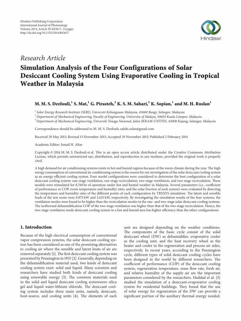
2.2.1. One-Stage Ventilation Mode. Figure 1 shows that theventilation mode of the solar desiccant cooling is an opencycle that provides supply air to the room from ambient air.
Backup heaterSolar
collec
torWater tank Pump
Pump
HX
HRWDW DEC 1Room
DEC 2
1 2 3 4
56789
SA
Exhaust air RA
Ambient air
Figure 1: Solar desiccant cooling in ventilation mode schematic.
Backup heater
Water tank Pump
Pump
HX
HRWDW DEC 1 Room
DEC 21 2 3 4
56789
SARA
Exhaust air
Ambient air
Solar co
llector
Figure 2: Solar desiccant cooling in recirculation mode schematic.
The returning air from the room after few processes isconverted to ambient temperature as exhaust air. Therefore,two kinds of air are present: the process side that produces
4 International Journal of Photoenergy
7
DW 1 DW 2 HRW 2HRW 1DEC 1
DEC 2
Room
HX 1 HX 2
Ambient air
Exhaust air Exhaust airExhaust airEx
haus
t air
1 2 3 4 5 6SA
RA
89101112131415
Am
bien
t air
Figure 3: Schematic of two-stage solar desiccant cooling system-ventilation mode.
DW 1 DW 2 HRW 2HRW 1DEC 1
DEC 2
Room
HX 1 HX 2
Ambient air
Exhaust air Exhaust airExhaust airExhaust air
1 2 3 4 5 6SA
RA
7891011121314
Figure 4: Schematic of two-stage solar desiccant cooling system-recirculation mode.
the supply air, and the regeneration side that releases thereturning air from room to ambient temperature. In theprocess side, first, the ambient air becomes dry because ofthe DW. Then, the heat recovery wheel cools the air in theprocess side. In the next step, the air becomes cold because ofthe evaporative cooler; then, the air moves into the room assupply air. In the regeneration side, the returning air whoselatent and sensible loads were left in the room becomes coldbecause of the evaporative cooler. The heat recovery wheelacts as an energy conservation wheel in the regeneration airside. Then, the heat from the heat exchanger is transferred tothe air. In the last step in the regeneration side, the hot air thusabsorbed the humidity of the DW and released it outside.
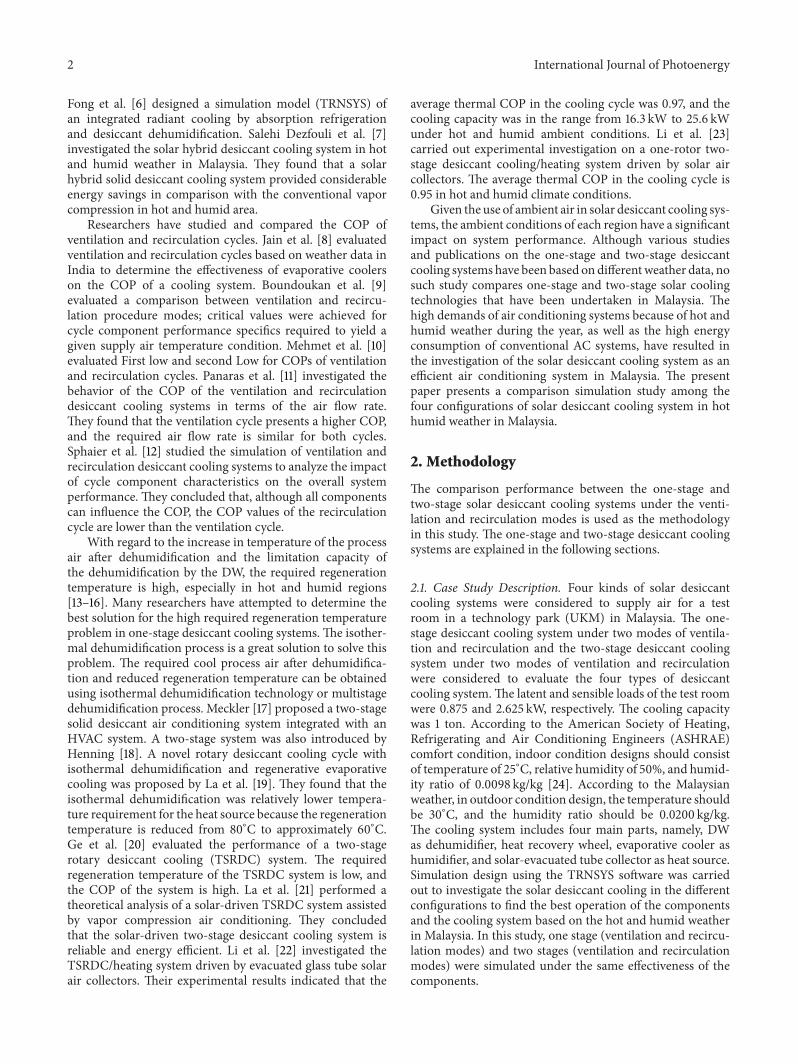
2.2.2. One-Stage Recirculation Mode. Figure 2 shows therecirculation mode of the solar desiccant cooling system.Generally, this system is not an open cycle. The process airside in the recirculation mode is a closed loop, whereas theregeneration air side is an open cycle.
In the process air side, the room air that includes thesensible and latent loads moves to the DW to remove thelatent load. The heat recovery wheel acts as a cooler in theprocess air side. In the next step, the air grows cold becauseof the evaporative cooler, and it moves into the room assupply air. In the regeneration side, the ambient air grows coldbecause of the evaporative cooler. In the next step, the heatfrom the solar collectors and the backup heater is transferredto the air by means of a heat exchanger. Thus, in the last step
in the regeneration side, the hot air absorbs the humidity ofthe DW and is released as exhaust air outdoors.
2.3. Two-Stage Solar Desiccant Cooling System. The two-stagesolar desiccant cooling includes the ventilation and recircu-lation modes. The components of the two-stage desiccantcooling system are two DWs, two heat recovery wheels,two evaporative coolers with different capacities, two heatexchangers, two auxiliary heaters, and an evacuated tubecollector. According to the high dehumidification capacity ofthe two-stage DW and the humid weather in Malaysia, theset point of dehumidification was adjusted at a 0.0050 kg/kghumidity ratio. The air flow rate of the two-stage ventilationand recirculation in the process side was 870.4 kg/hr and435.2 kg/hr in the regeneration side.
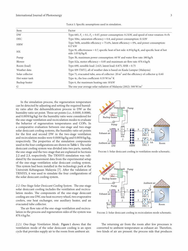
2.3.1. Two-Stage Ventilation Mode. Figure 3 shows the two-step dehumidification of the process air in the solar desiccantcooling system using the evaporative cooling units in venti-lation mode. This mode is an open cycle. The air propertiesof each of the 15 points are characterized by the simulationmodel. The air properties are explained in Section 3.
The supply air in the process side is produced from theambient air by undergoing a few stages, such as the two-step dehumidification in the DWs (2 and 4), two-step coolingin the heat recovery wheels (3 and 5), and one-step coolingin the direct evaporative cooler (6). In the regeneration airside, the returning air (7) is mixed with the ambient air (8)
International Journal of Photoenergy 5
0
10
20
30
40
50
60
70
80
90
100
Time (hr)
AmbientRegenerationRoom (load)
Supply airProcess air after DW
Supply air
Ambient
Room (load)
Process air after DW
Regeneration
Tem
pera
ture
(∘C)
85008000750070006500600055005000450040003500300025002000150010005000
Figure 5: Temperatures (∘C) of different components versus time (hr) in ventilation desiccant cooling system.
0.0000
0.0050
0.0100
0.0150
0.0200
0.0250
Hum
idity
ratio
(kg/
kg)
Time (hr)AmbientSupply air
Room (load)Process air after DW
Ambient
Supply air
Room (load)
Process air after DW
85008000750070006500600055005000450040003500300025002000150010005000
Figure 6: Humidity ratio (kg/kg) of different components versus time (hr) in ventilation desiccant cooling system.
before being cooled in one direct evaporative cooler. Then,the output air from the evaporative cooler (9) is divided intotwo stages with the same air flow rate. In each stage, air isheated in the heat recovery wheel (10 and 13), heated in thesolar heaters (11 and 14), and humidified in the DWs (12 and15).
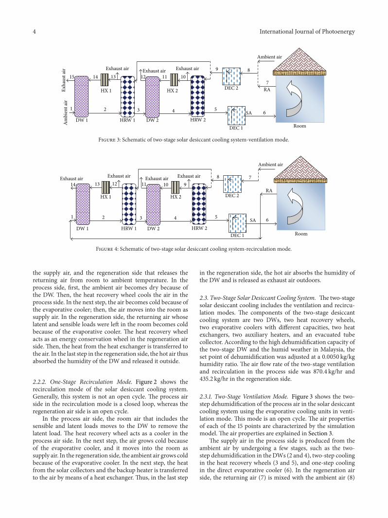
2.3.2. Two-Stage Recirculation Mode. Figure 4 shows theschematic of the two-stage solar desiccant cooling system
under the recirculation mode. The process air side (1–6) isa closed loop and the regeneration side (7–14) is an opencycle. Supply air is produced from the returning air in theprocess air side by undergoing a few stages, such as the two-step dehumidification in the DWs (2 and 4), two step coolingin the heat recovery wheels (3 and 5), and one-step coolingin the direct evaporative cooler (6). In the regeneration side,ambient air (7) is mixed from the air in the cooler (8) andthen divided into two stages for the heating and humidifying
6 International Journal of Photoenergy
process (8–11 and 8–14).The process air under the ventilationmode is an open loop, whereas it is a closed loop under therecirculation mode.
2.4. Determination of the COP of theDesiccant Cooling System.The COP of the solar desiccant cooling system can becalculated by the rate of heat extracted against the rate of thecooling system driving energy. The rate of heat extracted isthe cooling capacity of the system. The rate of the coolingsystemdriving energy is the total thermal energy requirementfor the cooling system generated from solar collectors and thebackup heater. Therefore, the COP of the system is obtainedby the following relationship [4]:
COP =𝑄cool𝑄𝑇
. (1)
2.4.1. One Stage. The COP of the solar desiccant coolingsystem under the ventilation mode is defined as the ratio ofthe enthalpy change from ambient air to supply air,multipliedby the mass air flow and external heat delivered to theregeneration heat exchanger. It can be written as follows:
COP =��𝑠(ℎ1− ℎ4)
��𝑟(ℎ8− ℎ7). (2)
The COP of the solar desiccant cooling under recirculationmode can be written as
COP =��𝑠(ℎ1− ℎ4)
��𝑟(ℎ8− ℎ7), (3)
where ��𝑠(kg/hr) is the mass flow rate of the supply air, ��
𝑟
(kg/hr) is the mass flow rate of the regeneration air, and ℎ(kJ/kg) is the enthalpy of air.
2.4.2. Two Stages. The COP of the two-stage solar desiccantcooling under the ventilation mode can be written as [20]
COP =��𝑠1(ℎ1− ℎ6)
��𝑟13(ℎ14− ℎ13) + ��𝑟10(ℎ11− ℎ10). (4)
The COP of the two-stage solar desiccant cooling under therecirculation mode can be written as
COP =��𝑠1(ℎ1− ℎ6)
��𝑟12(ℎ13− ℎ12) + ��𝑟9(ℎ10− ℎ9), (5)
where ��𝑠(kg/hr) is the mass flow rate of the supply air, ��
𝑟
(kg/hr) is the mass flow rate of the regeneration air, and ℎ(KJ/kg) is the enthalpy of air.
2.5. Solar Fraction. Generally, solar collectors convert solarradiation into thermal energy in solar cooling systems. Con-sidering the insufficient thermal energy from solar collectorsin cloudy weather, the backup heater is used to achieve therequired thermal energy for the total cooling system drivingenergy. The percentage ratio of the thermal energy producedby the solar collectors to the total cooling system driving
Table 2: Air properties of one-stage solar desiccant cooling systemin ventilation mode.
Points number Temperature (∘C) Humidity ratio (kg/kg)1 30 0.02002 49.5 0.01003 31.8 0.01004 22 0.01375 30.8 0.01526 24.95 0.01767 45.6 0.01768 81.6 0.01769 50 0.0262
energy is known as the solar fraction, which can be expressedas follows [25]:
SF =𝑄𝑈
𝑄𝑇
, (6)
where𝑄𝑇is the total cooling system driving energy produced
by the solar collectors and the backup heater. 𝑄𝑈
is thethermal energy produced by the solar collectors that can beexpressed as [26]
𝑄𝑈= 𝐴 × 𝜂 × 𝐺. (7)
3. Results and Discussion
The results of the four different systems were explained andthen compared in the next sections. The temperature andhumidity ratio against time of the specified points in the foursystems were analyzed.
3.1. Results of the One-Stage Solar Desiccant Cooling System
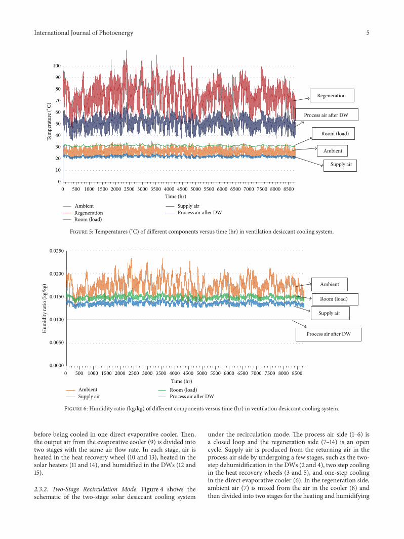
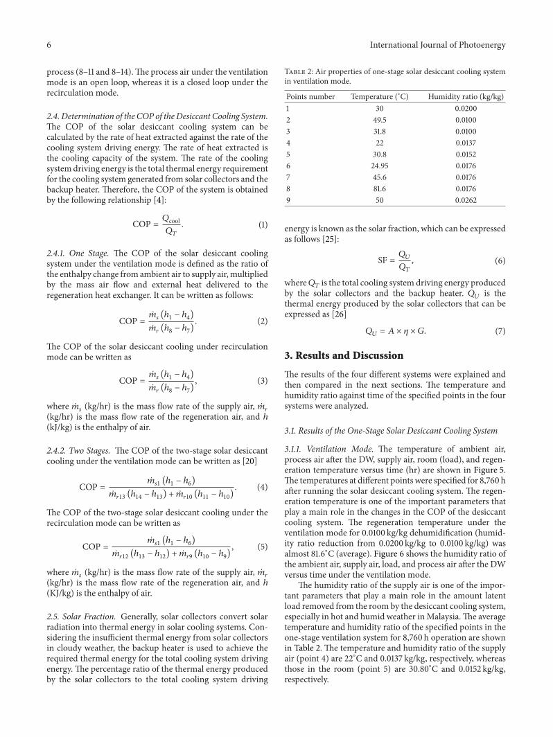
3.1.1. Ventilation Mode. The temperature of ambient air,process air after the DW, supply air, room (load), and regen-eration temperature versus time (hr) are shown in Figure 5.The temperatures at different points were specified for 8,760 hafter running the solar desiccant cooling system. The regen-eration temperature is one of the important parameters thatplay a main role in the changes in the COP of the desiccantcooling system. The regeneration temperature under theventilation mode for 0.0100 kg/kg dehumidification (humid-ity ratio reduction from 0.0200 kg/kg to 0.0100 kg/kg) wasalmost 81.6∘C (average). Figure 6 shows the humidity ratio ofthe ambient air, supply air, load, and process air after the DWversus time under the ventilation mode.
The humidity ratio of the supply air is one of the impor-tant parameters that play a main role in the amount latentload removed from the roomby the desiccant cooling system,especially in hot and humid weather inMalaysia.The averagetemperature and humidity ratio of the specified points in theone-stage ventilation system for 8,760 h operation are shownin Table 2. The temperature and humidity ratio of the supplyair (point 4) are 22∘C and 0.0137 kg/kg, respectively, whereasthose in the room (point 5) are 30.80∘C and 0.0152 kg/kg,respectively.
International Journal of Photoenergy 7
0.030
0.028
0.026
0.024
0.022
0.020
0.018
0.016
0.014
0.012
0.010
0.008
0.006
0.004
0.002
0.000
848076726864605652484440363228242016
Hum
idity
ratio
(kg/
kg)
Temperature (∘C)
1
2
3
4
6 7
8
9
5
100% R
elativ
e hum
idity
90%
80%70%
60%
50%
40%
30%
20%
10%
Figure 7: Psychometric chart of the one-stage solar desiccant cooling system under the ventilation mode.
0
10
20
30
40
50
60
70
80
90
100
Time (hr)AmbientRegenerationRoom (load)
Supply airProcess air after DW
Supply air
Ambient
Room (load)
Process air after DW
Regeneration
Tem
pera
ture
(∘C)
8500
8000
7500
7000
6500
6000
5500
5000
4500
4000
3500
3000
2500
2000
1500
1000
5000
Figure 8: Temperatures (∘C) of different components versus time (hr) in recirculation desiccant cooling system.
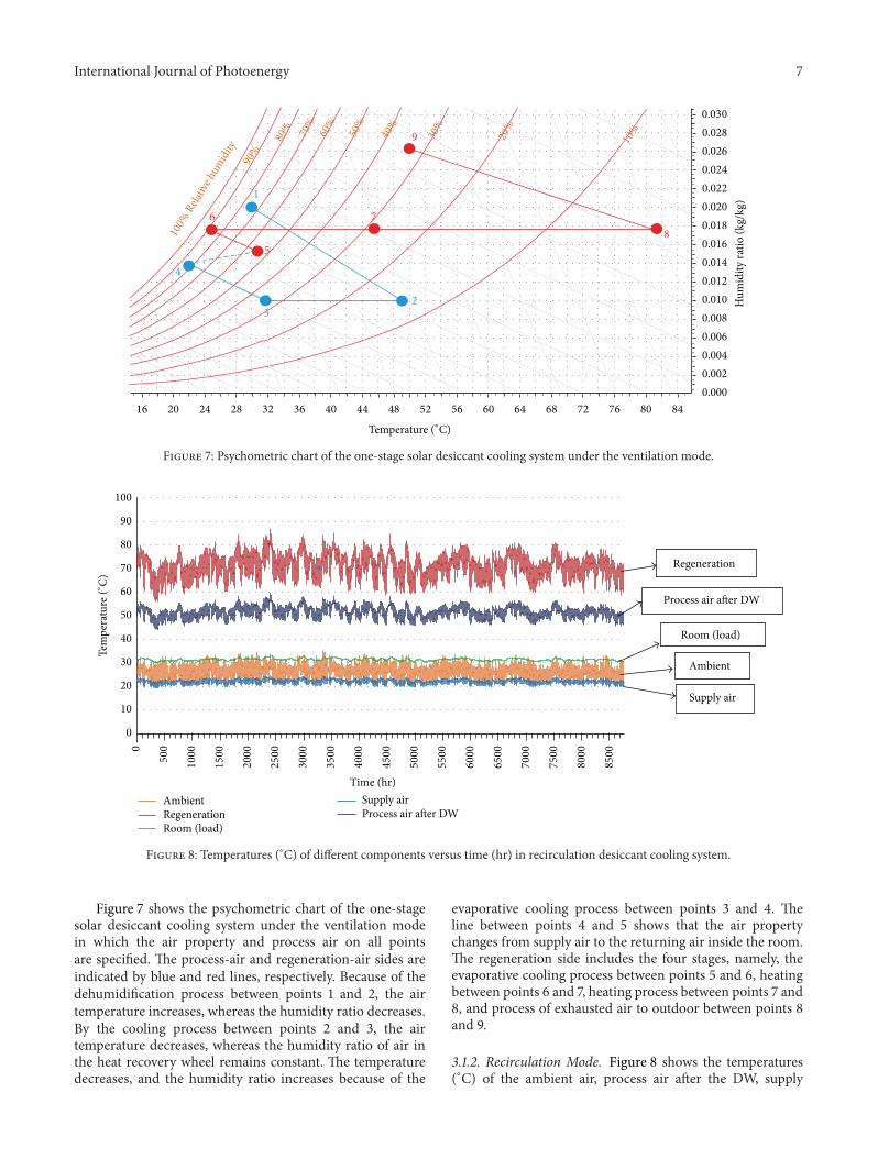
Figure 7 shows the psychometric chart of the one-stagesolar desiccant cooling system under the ventilation modein which the air property and process air on all pointsare specified. The process-air and regeneration-air sides areindicated by blue and red lines, respectively. Because of thedehumidification process between points 1 and 2, the airtemperature increases, whereas the humidity ratio decreases.By the cooling process between points 2 and 3, the airtemperature decreases, whereas the humidity ratio of air inthe heat recovery wheel remains constant. The temperaturedecreases, and the humidity ratio increases because of the
evaporative cooling process between points 3 and 4. Theline between points 4 and 5 shows that the air propertychanges from supply air to the returning air inside the room.The regeneration side includes the four stages, namely, theevaporative cooling process between points 5 and 6, heatingbetween points 6 and 7, heating process between points 7 and8, and process of exhausted air to outdoor between points 8and 9.
3.1.2. Recirculation Mode. Figure 8 shows the temperatures(∘C) of the ambient air, process air after the DW, supply
8 International Journal of Photoenergy
0.0000
0.0050
0.0100
0.0150
0.0200
0.0250
AmbientProcess air after DW
Ambient
Supply air
Hum
idity
ratio
(kg/
kg)
Room (load)
Process air after DW
Time (hr)
8500
8000
7500
7000
6500
6000
5500
5000
4500
4000
3500
3000
2500
2000
1500
1000
5000
Room (load)Supply air
Figure 9: Humidity ratio (kg/kg) of different components versus time (hr) in recirculation mode.
Table 3: Air properties of one-stage solar desiccant cooling systemin recirculation mode.
Points number Temperature (∘C) Humidity ratio (kg/kg)1 31 0.01502 51 0.01003 31.4 0.01004 21.4 0.01365 30 0.02006 26.4 0.02157 45 0.02158 70.2 0.02159 55 0.0257
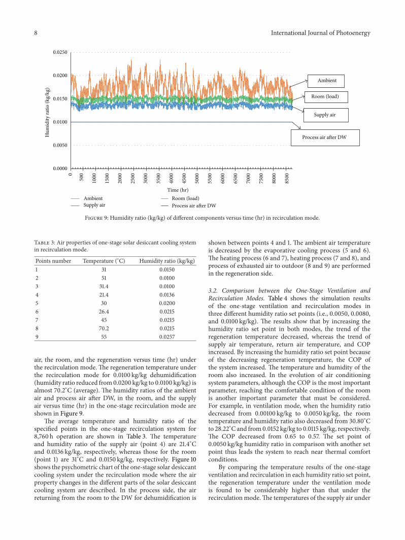
air, the room, and the regeneration versus time (hr) underthe recirculation mode. The regeneration temperature underthe recirculation mode for 0.0100 kg/kg dehumidification(humidity ratio reduced from0.0200 kg/kg to 0.0100 kg/kg) isalmost 70.2∘C (average). The humidity ratios of the ambientair and process air after DW, in the room, and the supplyair versus time (hr) in the one-stage recirculation mode areshown in Figure 9.
The average temperature and humidity ratio of thespecified points in the one-stage recirculation system for8,760 h operation are shown in Table 3. The temperatureand humidity ratio of the supply air (point 4) are 21.4∘Cand 0.0136 kg/kg, respectively, whereas those for the room(point 1) are 31∘C and 0.0150 kg/kg, respectively. Figure 10shows the psychometric chart of the one-stage solar desiccantcooling system under the recirculation mode where the airproperty changes in the different parts of the solar desiccantcooling system are described. In the process side, the airreturning from the room to the DW for dehumidification is
shown between points 4 and 1. The ambient air temperatureis decreased by the evaporative cooling process (5 and 6).The heating process (6 and 7), heating process (7 and 8), andprocess of exhausted air to outdoor (8 and 9) are performedin the regeneration side.
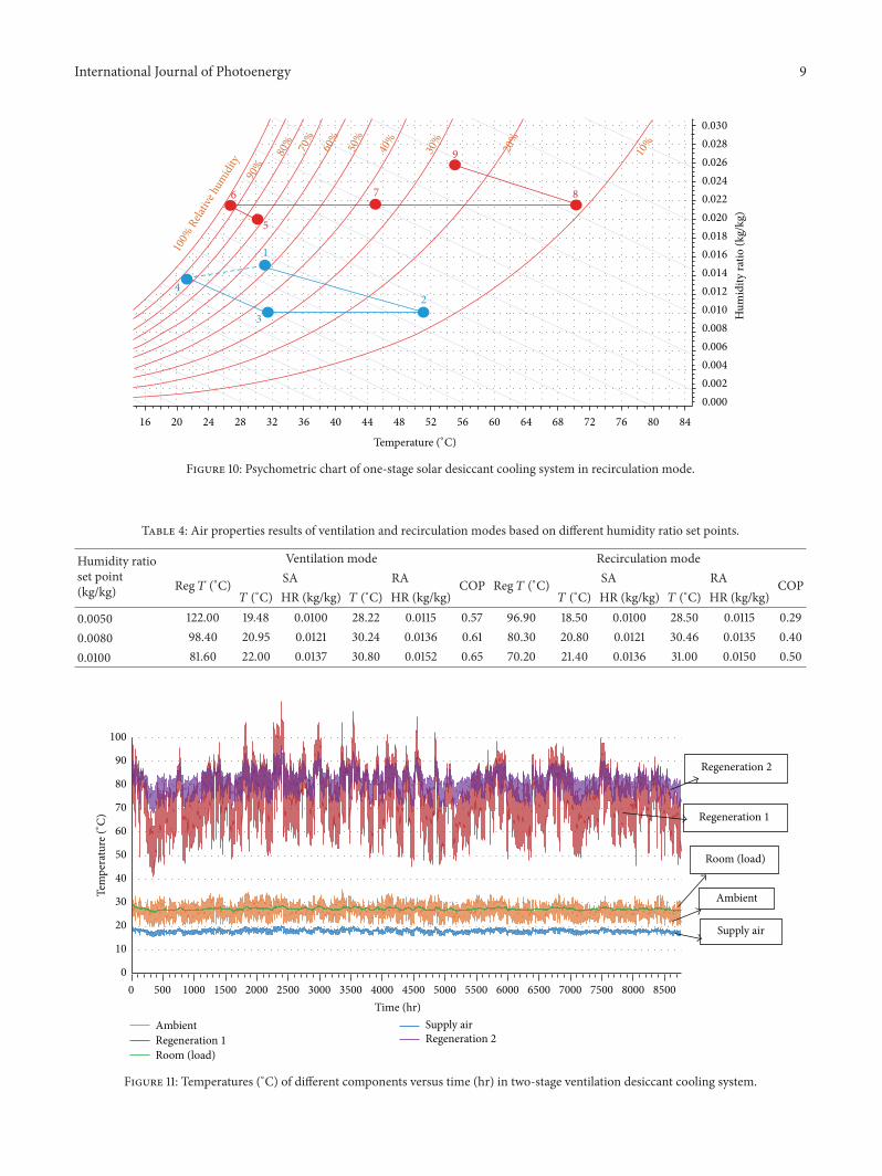
3.2. Comparison between the One-Stage Ventilation andRecirculation Modes. Table 4 shows the simulation resultsof the one-stage ventilation and recirculation modes inthree different humidity ratio set points (i.e., 0.0050, 0.0080,and 0.0100 kg/kg). The results show that by increasing thehumidity ratio set point in both modes, the trend of theregeneration temperature decreased, whereas the trend ofsupply air temperature, return air temperature, and COPincreased. By increasing the humidity ratio set point becauseof the decreasing regeneration temperature, the COP ofthe system increased. The temperature and humidity of theroom also increased. In the evolution of air conditioningsystem parameters, although the COP is the most importantparameter, reaching the comfortable condition of the roomis another important parameter that must be considered.For example, in ventilation mode, when the humidity ratiodecreased from 0.00100 kg/kg to 0.0050 kg/kg, the roomtemperature and humidity ratio also decreased from 30.80∘Cto 28.22∘Cand from0.0152 kg/kg to 0.0115 kg/kg, respectively.The COP decreased from 0.65 to 0.57. The set point of0.0050 kg/kg humidity ratio in comparison with another setpoint thus leads the system to reach near thermal comfortconditions.
By comparing the temperature results of the one-stageventilation and recirculation in each humidity ratio set point,the regeneration temperature under the ventilation modeis found to be considerably higher than that under therecirculation mode.The temperatures of the supply air under
International Journal of Photoenergy 9
848076726864605652484440363228242016
Temperature (∘C)
1
2
3
4
100% R
elativ
e hum
idity
90%
80%70%
60%
50%
40%
30%
20%
10%
5
6 7 8
9
0.030
0.028
0.026
0.024
0.022
0.020
0.018
0.016
0.014
0.012
0.010
0.008
0.006
0.004
0.002
0.000
Hum
idity
ratio
(kg/
kg)
Figure 10: Psychometric chart of one-stage solar desiccant cooling system in recirculation mode.
Table 4: Air properties results of ventilation and recirculation modes based on different humidity ratio set points.
Humidity ratioset point(kg/kg)
Ventilation mode Recirculation mode
Reg 𝑇 (∘C) SA RA COP Reg 𝑇 (∘C) SA RA COP𝑇 (∘C) HR (kg/kg) 𝑇 (∘C) HR (kg/kg) 𝑇 (∘C) HR (kg/kg) 𝑇 (∘C) HR (kg/kg)
0.0050 122.00 19.48 0.0100 28.22 0.0115 0.57 96.90 18.50 0.0100 28.50 0.0115 0.290.0080 98.40 20.95 0.0121 30.24 0.0136 0.61 80.30 20.80 0.0121 30.46 0.0135 0.400.0100 81.60 22.00 0.0137 30.80 0.0152 0.65 70.20 21.40 0.0136 31.00 0.0150 0.50
0
10
20
30
40
50
60
70
80
90
100
Time (hr)AmbientRegeneration 1Room (load)
Supply airRegeneration 2
Supply air
Room (load)
Ambient
Regeneration 1
Regeneration 2
85008000750070006500600055005000450040003500300025002000150010005000
Tem
pera
ture
(∘C)
Figure 11: Temperatures (∘C) of different components versus time (hr) in two-stage ventilation desiccant cooling system.
10 International Journal of Photoenergy
0.0000
0.0050
0.0100
0.0150
0.0200
0.0250H
umid
ity ra
tio (k
g/kg
)
Time (hr)Ambient
Supply airRoom (load)Process air after DW 1Process air after DW 2
Process air after DW 2
Process air after DW 1
Supply air
Room (load)
Ambient
85008000750070006500600055005000450040003500300025002000150010005000
Figure 12: Humidity ratio (kg/kg) of different components versus time (hr) in two-stage ventilation desiccant cooling system.
both modes are almost the same. In addition, the roomtemperatures under both modes are almost the same.
By comparison, the humidity ratio results of the ven-tilation and recirculation show that the humidity ratio ofthe room and the supply air under both modes are almostthe same. The COPs under the ventilation and recirculationmodes are calculated using (1) and (2). Therefore, the COPsof the desiccant cooling system under the ventilation modeare higher than those under the recirculation mode.
3.3. Result of the Two-Stage Solar Desiccant Cooling System.The simulation results of the two-stage desiccant coolingsystem under the two modes of ventilation and recirculationare explained in the following sections.
3.3.1. Two-StageVentilation . Figure 11 shows the temperaturetrend in the different points of the two-stage solar desiccantsystem, such as the temperatures of the regeneration ofthe first and second DWs, room, ambient air, and supplyair versus time (hr). The first and second regenerationtemperatures are approximately 80∘C. The humidity ratio ofthe ambient air, process air after DW, room, and supply airversus time (hr) under the two-stage ventilation mode areshown in Figure 12.
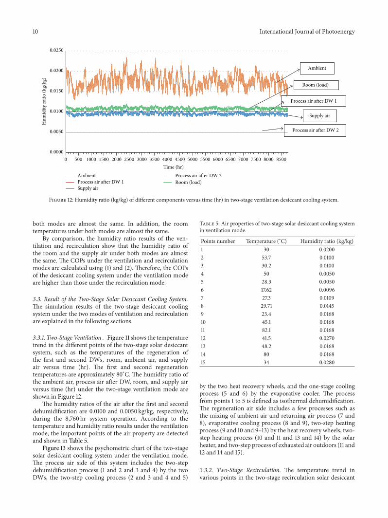
The humidity ratios of the air after the first and seconddehumidification are 0.0100 and 0.0050 kg/kg, respectively,during the 8,760 hr system operation. According to thetemperature and humidity ratio results under the ventilationmode, the important points of the air property are detectedand shown in Table 5.
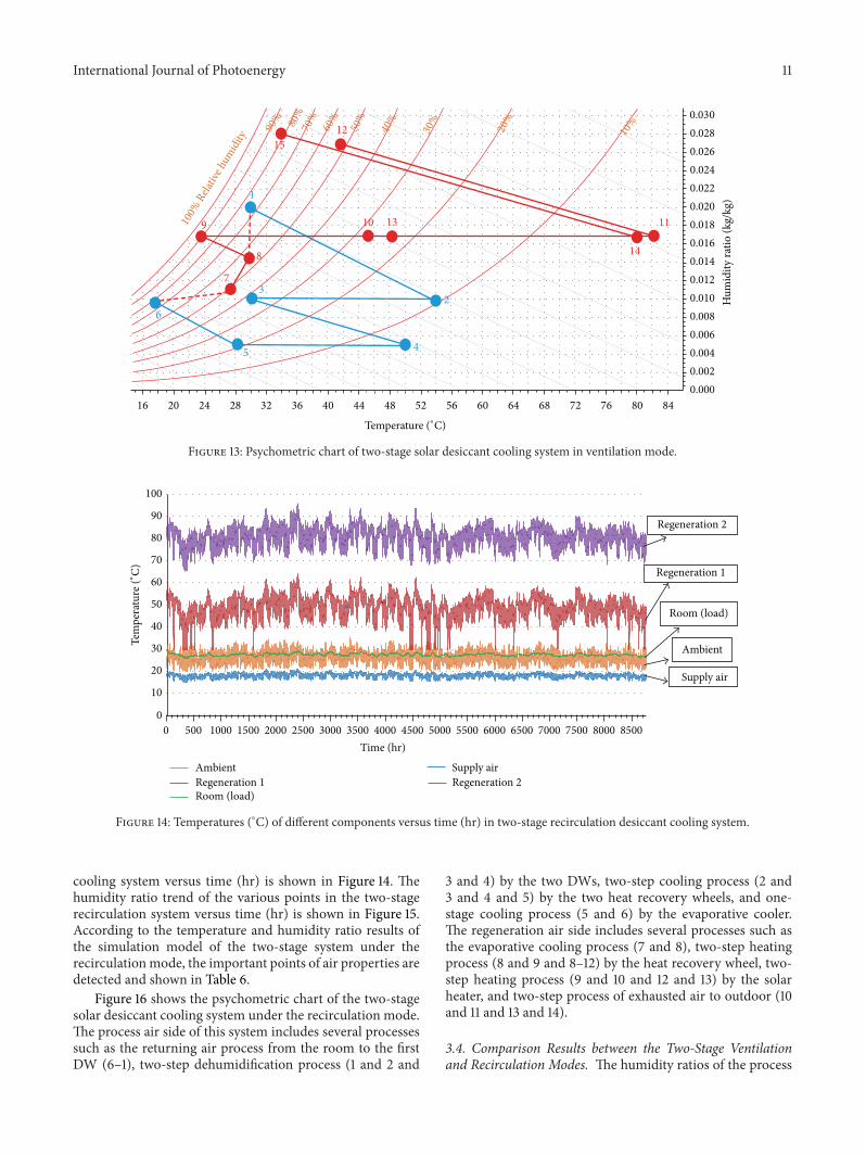
Figure 13 shows the psychometric chart of the two-stagesolar desiccant cooling system under the ventilation mode.The process air side of this system includes the two-stepdehumidification process (1 and 2 and 3 and 4) by the twoDWs, the two-step cooling process (2 and 3 and 4 and 5)
Table 5: Air properties of two-stage solar desiccant cooling systemin ventilation mode.
Points number Temperature (∘C) Humidity ratio (kg/kg)1 30 0.02002 53.7 0.01003 30.2 0.01004 50 0.00505 28.3 0.00506 17.62 0.00967 27.3 0.01098 29.71 0.01459 23.4 0.016810 45.1 0.016811 82.1 0.016812 41.5 0.027013 48.2 0.016814 80 0.016815 34 0.0280
by the two heat recovery wheels, and the one-stage coolingprocess (5 and 6) by the evaporative cooler. The processfrom points 1 to 5 is defined as isothermal dehumidification.The regeneration air side includes a few processes such asthe mixing of ambient air and returning air process (7 and8), evaporative cooling process (8 and 9), two-step heatingprocess (9 and 10 and 9–13) by the heat recovery wheels, two-step heating process (10 and 11 and 13 and 14) by the solarheater, and two-step process of exhausted air outdoors (11 and12 and 14 and 15).
3.3.2. Two-Stage Recirculation. The temperature trend invarious points in the two-stage recirculation solar desiccant
International Journal of Photoenergy 11
848076726864605652484440363228242016
Hum
idity
ratio
(kg/
kg)
Temperature (∘C)
1
2
3
4
100% R
elativ
e hum
idity
90%80%
70%
60%
50%
40%
30%
20%
10%
5
6
7
8
9 10 11
12
13
14
15
0.030
0.028
0.026
0.024
0.022
0.020
0.018
0.016
0.014
0.012
0.010
0.008
0.006
0.004
0.002
0.000
Figure 13: Psychometric chart of two-stage solar desiccant cooling system in ventilation mode.
0
10
20
30
40
50
60
70
80
90
100
Time (hr)
AmbientRegeneration 1Room (load)
Supply airRegeneration 2
Ambient
Room (load)
Supply air
Regeneration 1
Regeneration 2
Tem
pera
ture
(∘C)
85008000750070006500600055005000450040003500300025002000150010005000
Figure 14: Temperatures (∘C) of different components versus time (hr) in two-stage recirculation desiccant cooling system.
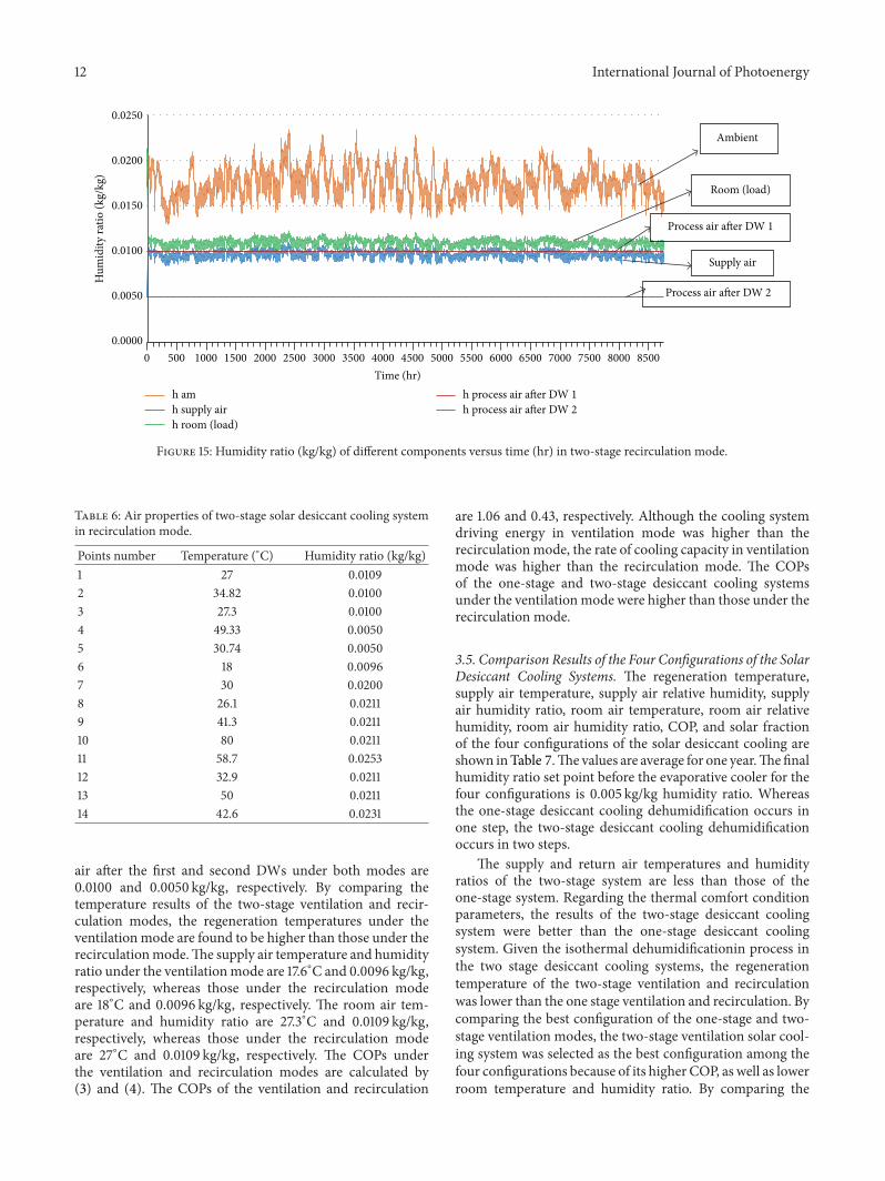
cooling system versus time (hr) is shown in Figure 14. Thehumidity ratio trend of the various points in the two-stagerecirculation system versus time (hr) is shown in Figure 15.According to the temperature and humidity ratio results ofthe simulation model of the two-stage system under therecirculationmode, the important points of air properties aredetected and shown in Table 6.
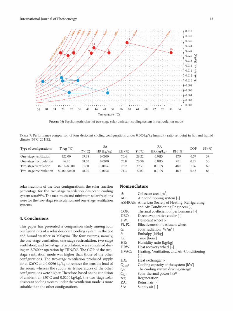
Figure 16 shows the psychometric chart of the two-stagesolar desiccant cooling system under the recirculation mode.The process air side of this system includes several processessuch as the returning air process from the room to the firstDW (6–1), two-step dehumidification process (1 and 2 and
3 and 4) by the two DWs, two-step cooling process (2 and3 and 4 and 5) by the two heat recovery wheels, and one-stage cooling process (5 and 6) by the evaporative cooler.The regeneration air side includes several processes such asthe evaporative cooling process (7 and 8), two-step heatingprocess (8 and 9 and 8–12) by the heat recovery wheel, two-step heating process (9 and 10 and 12 and 13) by the solarheater, and two-step process of exhausted air to outdoor (10and 11 and 13 and 14).
3.4. Comparison Results between the Two-Stage Ventilationand Recirculation Modes. The humidity ratios of the process
12 International Journal of Photoenergy
0.0000
0.0050
0.0100
0.0150
0.0200
0.0250H
umid
ity ra
tio (k
g/kg
)
Time (hr) h amh supply airh room (load)
h process air after DW 1h process air after DW 2
Process air after DW 2
Process air after DW 1
Supply air
Room (load)
Ambient
85008000750070006500600055005000450040003500300025002000150010005000
Figure 15: Humidity ratio (kg/kg) of different components versus time (hr) in two-stage recirculation mode.
Table 6: Air properties of two-stage solar desiccant cooling systemin recirculation mode.
Points number Temperature (∘C) Humidity ratio (kg/kg)1 27 0.01092 34.82 0.01003 27.3 0.01004 49.33 0.00505 30.74 0.00506 18 0.00967 30 0.02008 26.1 0.02119 41.3 0.021110 80 0.021111 58.7 0.025312 32.9 0.021113 50 0.021114 42.6 0.0231
air after the first and second DWs under both modes are0.0100 and 0.0050 kg/kg, respectively. By comparing thetemperature results of the two-stage ventilation and recir-culation modes, the regeneration temperatures under theventilationmode are found to be higher than those under therecirculationmode.The supply air temperature and humidityratio under the ventilationmode are 17.6∘C and 0.0096 kg/kg,respectively, whereas those under the recirculation modeare 18∘C and 0.0096 kg/kg, respectively. The room air tem-perature and humidity ratio are 27.3∘C and 0.0109 kg/kg,respectively, whereas those under the recirculation modeare 27∘C and 0.0109 kg/kg, respectively. The COPs underthe ventilation and recirculation modes are calculated by(3) and (4). The COPs of the ventilation and recirculation
are 1.06 and 0.43, respectively. Although the cooling systemdriving energy in ventilation mode was higher than therecirculationmode, the rate of cooling capacity in ventilationmode was higher than the recirculation mode. The COPsof the one-stage and two-stage desiccant cooling systemsunder the ventilationmode were higher than those under therecirculation mode.
3.5. Comparison Results of the Four Configurations of the SolarDesiccant Cooling Systems. The regeneration temperature,supply air temperature, supply air relative humidity, supplyair humidity ratio, room air temperature, room air relativehumidity, room air humidity ratio, COP, and solar fractionof the four configurations of the solar desiccant cooling areshown inTable 7.The values are average for one year.Thefinalhumidity ratio set point before the evaporative cooler for thefour configurations is 0.005 kg/kg humidity ratio. Whereasthe one-stage desiccant cooling dehumidification occurs inone step, the two-stage desiccant cooling dehumidificationoccurs in two steps.
The supply and return air temperatures and humidityratios of the two-stage system are less than those of theone-stage system. Regarding the thermal comfort conditionparameters, the results of the two-stage desiccant coolingsystem were better than the one-stage desiccant coolingsystem. Given the isothermal dehumidificationin process inthe two stage desiccant cooling systems, the regenerationtemperature of the two-stage ventilation and recirculationwas lower than the one stage ventilation and recirculation. Bycomparing the best configuration of the one-stage and two-stage ventilation modes, the two-stage ventilation solar cool-ing system was selected as the best configuration among thefour configurations because of its higher COP, as well as lowerroom temperature and humidity ratio. By comparing the
International Journal of Photoenergy 13
848076726864605652484440363228242016
Hum
idity
ratio
(kg/
kg)
Temperature (∘C)
1
2
3
4
100% R
elativ
e hum
idity
90%80%
70%
60%
50%
40%
30%
20%
10%
5
6
7
8 910
11
12 13
14
0.030
0.028
0.026
0.024
0.022
0.020
0.018
0.016
0.014
0.012
0.010
0.008
0.006
0.004
0.002
0.000
Figure 16: Psychometric chart of two-stage solar desiccant cooling system in recirculation mode.
Table 7: Performance comparison of four desiccant cooling configurations under 0.005 kg/kg humidity ratio set point in hot and humidclimate (30∘C, 20HR).
Type of configurations 𝑇 reg (∘C) SA RA COP SF (%)𝑇 (∘C) HR (kg/kg) RH (%) 𝑇 (∘C) HR (kg/kg) RH (%)
One-stage ventilation 122.00 19.48 0.0100 70.4 28.22 0.0115 47.9 0.57 39One-stage recirculation 96.90 18.50 0.0100 75.0 28.50 0.0115 47.1 0.29 50Two-stage ventilation 82.10–80.00 17.60 0.0096 76.2 27.30 0.0109 48.0 1.06 69Two-stage recirculation 80.00–50.00 18.00 0.0096 74.3 27.00 0.0109 48.7 0.43 85
solar fractions of the four configurations, the solar fractionpercentage for the two-stage ventilation desiccant coolingsystemwas 69%.Themaximumandminimum solar fractionswere for the two-stage recirculation and one-stage ventilationsystems.
4. Conclusions
This paper has presented a comparison study among fourconfigurations of a solar desiccant cooling system in the hotand humid weather in Malaysia. The four systems, namely,the one-stage ventilation, one-stage recirculation, two-stageventilation, and two-stage recirculation, were simulated dur-ing an 8,760 hr operation by TRNSYS. The COP of the two-stage ventilation mode was higher than those of the otherconfigurations. The two-stage ventilation produced supplyair at 17.6∘C and 0.0096 kg/kg to remove the sensible load ofthe room, whereas the supply air temperatures of the otherconfigurationswere higher.Therefore, based on the conditionof ambient air (30∘C and 0.0200 kg/kg), the two-stage solardesiccant cooling system under the ventilation mode is moresuitable than the other configurations.
Nomenclature
𝐴: Collector area [m2]AC: Air conditioning system [-]ASHRAE: American Society of Heating, Refrigerating
and Air Conditioning Engineers [-]COP: Thermal coefficient of performance [-]DEC: Direct evaporative cooler [-]DW: Desiccant wheel [-]F1, F2: Effectiveness of desiccant wheel𝐺: Solar radiation [W/m2]ℎ: Enthalpy [kj/kg]hr: Time [hour]HR: Humidity ratio [kg/kg]HRW: Heat recovery wheel [-]HVAC: Heating, Ventilation, and Air-Conditioning
[-]HX: Heat exchanger [-]𝑄cool: Cooling capacity of the system [kW]𝑄𝑇: The cooling system driving energy𝑄𝑈: Solar thermal power [kW]
reg: RegenerationRA: Return air [-]SA: Supply air [-]
14 International Journal of Photoenergy
SF: Solar fraction [%]𝑇: Air temperature [∘C]TSRDC: Two-stage rotary desiccant cooling [-]��𝑠: Mass flow rate of the supply air [kg/hr]��𝑟: Mass flow rate of regeneration air [kg/hr]𝜂: Solar collector efficiency [-].
Conflict of Interests
The authors of the paper do not have any financial relationwith the TRNSYS software company. They confirm that thepaper is just a research workwhich has no financial benefitfrom TRNSYS Company or other companies.
Acknowledgment
The authors would like to thank the Solar Energy ResearchInstitute (SERI), Universiti KebangsaanMalaysia, for provid-ing the laboratory facilities and technical support.
References
[1] D. La, Y. J. Dai, Y. Li, R. Z. Wang, and T. S. Ge, “Technicaldevelopment of rotary desiccant dehumidification and air con-ditioning: a review,” Renewable and Sustainable Energy Reviews,vol. 14, no. 1, pp. 130–147, 2010.
[2] E. Hurdogan, O. Buyukalaca, T. Yılmaz, and A. Hepbaslı,“Experimental investigation of a novel desiccant cooling sys-tem,” Energy and Buildings, vol. 42, no. 11, pp. 2049–2060, 2010.
[3] A. Y. T. Al-Zubaydi, “Solar air conditioning and refrigerationwith absorption chillers technology in australia—an overviewon researches and applications,” Journal of Advanced Science andEngineering Research, vol. 1, no. 1, pp. 23–41, 2011.
[4] K. Daou, R. Z. Wang, and Z. Z. Xia, “Desiccant coolingair conditioning: a review,” Renewable and Sustainable EnergyReviews, vol. 10, no. 2, pp. 55–77, 2006.
[5] K. Haddad, B. Ouazia, and H. Barhoun, “Simulation of adesiccant-evaporative cooling system for residential buildings,”in Proceedings of the 3rd Canadian Solar Building Conference,pp. 1–8, Fredericton, Canada, August 2008.
[6] K. F. Fong, V. I. Hanby, and T. T. Chow, “HVAC systemoptimization for energymanagement by evolutionary program-ming,” Energy and Buildings, vol. 38, no. 3, pp. 220–231, 2006.
[7] M. M. Salehi Dezfouli, Z. Hashim, M. H. Ruslan, B. Bakhtyar,K. Sopian, andA. Zaharim, “Experimental investigation of solarhybrid desiccant cooling system in hot and humid weather ofmalaysia,” in Proceedings of the 10th International Conference onEnvironment, Ecosystems and Development (WSEAS ’12), 2012.
[8] S. Jain, P. L. Dhar, and S. C. Kaushik, “Evaluation of solid-desiccant-based evaporative cooling cycles for typical hot andhumid climates,” International Journal of Refrigeration, vol. 18,no. 5, pp. 287–296, 1995.
[9] P. Bourdoukan, E.Wurtz, and P. Joubert, “Comparison betweenthe conventional and recirculation modes in desiccant coolingcycles and deriving critical efficiencies of components,” Energy,vol. 35, no. 2, pp. 1057–1067, 2010.
[10] K. Mehmet, M. Ozdinc Carpınlıoglu, andM. Yıldırım, “Energyand exergy analyses of an experimental open-cycle desiccantcooling system,” Applied Thermal Engineering, vol. 24, no. 5-6,pp. 919–932, 2004.
[11] G. Panaras, E. Mathioulakis, and V. Belessiotis, “Achievableworking range for solid all-desiccant air-conditioning systemsunder specific space comfort requirements,” Energy and Build-ings, vol. 39, no. 9, pp. 1055–1060, 2007.
[12] L. A. Sphaier and C. E. L. Nobrega, “Parametric analysis ofcomponents effectiveness on desiccant cooling system perfor-mance,” Energy, vol. 38, no. 1, pp. 157–166, 2012.
[13] Z. Huan and N. Jianlei, “Two-stage desiccant cooling systemusing low-temperature heat,” Building Services EngineeringResearch and Technology, vol. 20, no. 2, pp. 51–55, 1999.
[14] Z. Q. Xiong, Y. J. Dai, and R. Z. Wang, “Development of a noveltwo-stage liquid desiccant dehumidification system assisted byCaCl2 solution using exergy analysis method,” Applied Energy,vol. 87, no. 5, pp. 1495–1504, 2010.
[15] S. Techajunta, S. Chirarattananon, and R. H. B. Exell, “Experi-ments in a solar simulator on solid desiccant regeneration andair dehumidification for air conditioning in a tropical humidclimate,” Renewable Energy, vol. 17, no. 4, pp. 549–568, 1999.
[16] K.-H. Yang and S.-H. Wang, “The analysis of a solar-assisteddesiccant evaporative cooling system and its application,” Jour-nal of the Chinese Institute of Engineers, vol. 11, no. 3, pp. 227–234, 1988.
[17] G.Meckler, “Two-stage desiccant dehumidification in commer-cial building HVAC systems,” Ashrae Transactions, vol. 95, no.2, pp. 1116–1123, 1989.
[18] H.-M. Henning, “Solar assisted air conditioning of buildings—an overview,” Applied Thermal Engineering, vol. 27, no. 10, pp.1734–1749, 2007.
[19] D. La, Y. Dai, Y. Li, T. Ge, and R.Wang, “Case study and theoret-ical analysis of a solar driven two-stage rotary desiccant coolingsystem assisted by vapor compression air-conditioning,” SolarEnergy, vol. 85, no. 11, pp. 2997–3009, 2011.
[20] T. S. Ge, Y. Li, R. Z. Wang, and Y. J. Dai, “Experimental studyon a two-stage rotary desiccant cooling system,” InternationalJournal of Refrigeration, vol. 32, no. 3, pp. 498–508, 2009.
[21] D. La, Y. Li, Y. J. Dai, T. S. Ge, and R. Z. Wang, “Developmentof a novel rotary desiccant cooling cycle with isothermaldehumidification and regenerative evaporative cooling usingthermodynamic analysis method,” Energy, vol. 44, no. 1, pp.778–791, 2012.
[22] H. Li, Y. J. Dai, Y. Li, D. La, and R. Z. Wang, “Case study ofa two-stage rotary desiccant cooling/heating system driven byevacuated glass tube solar air collectors,” Energy and Buildings,vol. 47, pp. 107–112, 2012.
[23] H. Li, Y. J. Dai, Y. Li, D. La, andR. Z.Wang, “Experimental inves-tigation on a one-rotor two-stage desiccant cooling/heating sys-tem driven by solar air collectors,”AppliedThermal Engineering,vol. 31, no. 17-18, pp. 3677–3683, 2011.
[24] ASHRAE Handbook—HVAC Systems and Equipment, Ameri-can Society of Heating, Refrigerating, and Air ConditioningEngineers, Atlanta, Ga, USA, 1996.
[25] A. M. Baniyounes, G. Liu, M. G. Rasul, and M. M. K. Khan,“Analysis of solar desiccant cooling system for an institutionalbuilding in subtropical Queensland, Australia,” Renewable andSustainable Energy Reviews, vol. 16, no. 8, pp. 6423–6431, 2012.
[26] Solar-Assisted Air-Conditioning in Buildings: A Handbook ForPlanners, Springer, New York, NY, USA, 2004.

Submit your manuscripts athttp://www.hindawi.com
Hindawi Publishing Corporationhttp://www.hindawi.com Volume 2014
Inorganic ChemistryInternational Journal of
Hindawi Publishing Corporation http://www.hindawi.com Volume 2014
International Journal ofPhotoenergy
Hindawi Publishing Corporationhttp://www.hindawi.com Volume 2014
Carbohydrate Chemistry
International Journal of
Hindawi Publishing Corporationhttp://www.hindawi.com Volume 2014
Journal of
Chemistry
Hindawi Publishing Corporationhttp://www.hindawi.com Volume 2014
Advances in
Physical Chemistry
Hindawi Publishing Corporationhttp://www.hindawi.com
Analytical Methods in Chemistry
Journal of
Volume 2014
Bioinorganic Chemistry and ApplicationsHindawi Publishing Corporationhttp://www.hindawi.com Volume 2014
SpectroscopyInternational Journal of
Hindawi Publishing Corporationhttp://www.hindawi.com Volume 2014
The Scientific World JournalHindawi Publishing Corporation http://www.hindawi.com Volume 2014
Medicinal ChemistryInternational Journal of
Hindawi Publishing Corporationhttp://www.hindawi.com Volume 2014
Chromatography Research International
Hindawi Publishing Corporationhttp://www.hindawi.com Volume 2014
Applied ChemistryJournal of
Hindawi Publishing Corporationhttp://www.hindawi.com Volume 2014
Hindawi Publishing Corporationhttp://www.hindawi.com Volume 2014
Theoretical ChemistryJournal of
Hindawi Publishing Corporationhttp://www.hindawi.com Volume 2014
Journal of
Spectroscopy
Analytical ChemistryInternational Journal of
Hindawi Publishing Corporationhttp://www.hindawi.com Volume 2014
Journal of
Hindawi Publishing Corporationhttp://www.hindawi.com Volume 2014
Quantum Chemistry
Hindawi Publishing Corporationhttp://www.hindawi.com Volume 2014
Organic Chemistry International
ElectrochemistryInternational Journal of
Hindawi Publishing Corporation http://www.hindawi.com Volume 2014
Hindawi Publishing Corporationhttp://www.hindawi.com Volume 2014
CatalystsJournal of