REGULATEUR - AVR R 129 · 2014-11-25 · 1.1.4. Réglage du regulateur R 129 1.1.4.1. Réglages du...
15
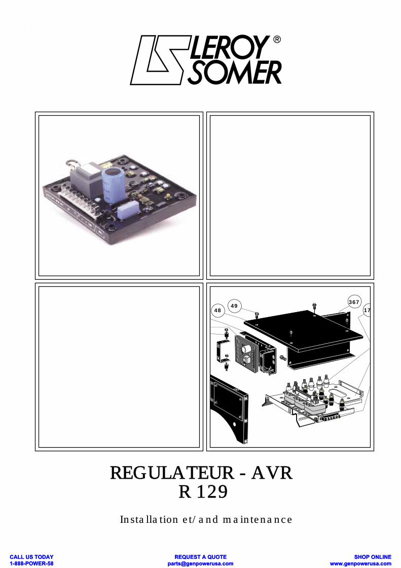
48 172 367 49 REGULATEUR - AVR R 129 Installation et/and maintenance CALL US TODAY 1-888-POWER-58 REQUEST A QUOTE [email protected] SHOP ONLINE www.genpowerusa.com CALL US TODAY 1-888-POWER-58 REQUEST A QUOTE [email protected] SHOP ONLINE www.genpowerusa.com
Transcript of REGULATEUR - AVR R 129 · 2014-11-25 · 1.1.4. Réglage du regulateur R 129 1.1.4.1. Réglages du...
48 172367
49
REGULATEUR - AVR R 129
Installation et/and maintenance
CALL US TODAY 1-888-POWER-58
REQUEST A QUOTE [email protected]
SHOP ONLINE www.genpowerusa.com
CALL US TODAY 1-888-POWER-58
REQUEST A QUOTE [email protected]
SHOP ONLINE www.genpowerusa.com

1.1 - Régulateur de tension R 129ATTENTION : IL EST DANGEREUX DE PROCÉDER AUN ESSAI DIELECTRIQUE SUR L'ALTERNATEURSANS DÉBRANCHER TOUTES LES LIAISONS AU RÉ-GULATEUR. LES DOMMAGES CAUSÉS AU RÉGULATEUR DANSDE TELLES CONDITIONS NE SONT PAS COUVERTSPAR NOTRE GARANTIE.
1.1.1 - DescriptionLes composants électroniques montés dans un boitierplastique sont enrobés dans un élastomère opaque. Leraccordement se fait à partir de languettes mâles "Faston" 6,3. Le régulateur comprend :- un bornier principal J1 (10 bornes repérées)- un bornier secondaire J2 (2 bornes repérées)- un potentiomètre de statisme : P1- un potentiomètre de tension : P2- un potentiomètre de fréquence : P3- un potentiomètre de stabilité : P4- un potentiomètre Exc maxi : P5- un potentiomètre statisme interne : P6
1.1.2 - Caractéristiques1.1.2.1. Fonction de base
Nota : * : S.A.H. : Sens anti horaire * : S.H. : Sens horaire- Régulateur soustractif (dérivation de courant)- Régulation de tension ± 1% entre marche à vide etpleine charge (non déformante) à vitesse et températurestabilisées.- Plage de réglage de tension du potentiomètre interne(P2) 50 et 60 Hz.- Entrée mesure 220 V : 170 à 250 V- Entrée mesure 380 V : 340 à 500 V- Potentiomètre extérieur : 470Ω - 1W (réglage ±10%).- Détection monophasée 2 VA isolée par transformateur,option module de détection triphasé (R.....) raccordée àl'entrée"potentiomètre extérieur"- Puissance controlée nominale (courant continu) :
1.1 - Automatic Voltage Regulator R 129CAUTION : IT IS HAZARDOUS TO PROCEED TO ANYHIGH VOLTAGE TEST ON THE ALTERNATOR WI-THOUT HAVING PREVIOUSLY DISCONNECTED ALLCONNECTIONS TO VOLTAGE REGULATOR.DAMAGES OCCURING TO AVR IN SUCH CONDITIONSWILL NOT BE CONSIDERED IN A WARRANTY CLAIM.
1.1.1 - GeneralThe PC board with electronic components is located inside an insulating plastic box and embeded in elastomereresin.Terminals consist in 1/4" "Faston" lugs.For connections and adjustments are :- main terminal strip J1 (10 marked terminal)- terminal strip J2 (2 marked terminal)- potentiometer (screw) droop : P1- potentiometer (screw) voltage : P2- potentiometer (screw) frequency : P3- potentiometer (screw) stability : P4- potentiometer (screw) excitation ceiling : P5- potentiometer (screw) internal voltage droop : P6
1.1.2 - Regulators data1.1.2.1. Basic fonction Note : * : CCW : Counter clockwise * : CW : Clockwise- Negative action A.V.R. (diverting excitation current)- Voltage accuracy ±1% between no-load and full rated load(not distorting) with stabilized speed and temperature.- Voltage range adjustment with internal potentiometer (P2)(50 or 60 Hz)- Sensing input 220V : 170 to 250 V- Sensing input 380V : 340 to 500 V- Remote trimmer 470Ω-1W (Range ±10%)- Sensing input power 2VA, single phase, insulated bytransformer. Optionnal three phase sensing module (R...)connected in lieu of remote trimmer.- Rated controlled power (DC) : 90V-7A Peak power (10 seconds) : 100V - 10A
2
Alternateur ACT - ACT/R Régulator R 129
Alternator ACT - ACT/R AVR R 129
125
140
J1
P1
115
100
Ø 5,8
P3P4
P5 P2P6
J2
55
CALL US TODAY 1-888-POWER-58
REQUEST A QUOTE [email protected]
SHOP ONLINE www.genpowerusa.com
CALL US TODAY 1-888-POWER-58
REQUEST A QUOTE [email protected]
SHOP ONLINE www.genpowerusa.com

90V.7A - En crète (10 secondes) : 100V.10ACourant dérivé nominal: 4 A crète 10 A
4.1.2.2. Fonctions supplémentaires- Marche en parallèle avec d'autres alternateurs2 possibilités sont offertes :- entre machines identiques ; statisme interne (proporti-onnel à la tension d'excitation) réglage par P6.- Universel; avec T.I. (2 V.A. secondaire 1 A). Statismeproportionnel à la puissance réactive , réglage par P1.- Marche en parallèle avec le réseau, avec T.I. (2 VA, 1A)avec module additionnel (R180, R725) raccordé àl'entrée potentiomètre extérieur.- Limitation d'excitationLe potentiométre (P5) permet de réduire la tensionmaximum d'excitation (réduction du courant de court-circuit permanent. 4.1.2.3. Potentiomètre extérieur : 470Ω-1WSe branche à la place du strap J2. Ces 2 bornes permettent le raccordement d'un module extérieur en parallèlesur le réseau. (RS 180 ou R725) ou d'un module dedétection triphasé.
4.1.2.4. AntiparasitageLe régulateur répond à la norme V.D.E. 0875. classe:NModule additionnel pour class K
1.1.3 - LAM- LAM : action éliminée en coupant le strap ST5
- Rôle du "LAM" (Atténuateur d'à coups de charge).A l'application d'une charge, la vitesse de rotation dugroupe électrogène diminue. Quand celle-ci passe endessous du seuil de fréquence préréglé, le "LAM" faitchuter la tension d'environ 15% et de ce fait l'échelon decharge active appliqué est réduit d'environ 25%, tant quela vitesse n'est pas remontée à sa valeur nominale.
Le "LAM" permet donc, soit de réduire la varia-tion de vitesse (fréquence) et sa durée pour unecharge appliquée donnée, soit d'augmenter lacharge appliquée possible pour une même va-riation de vitesse (moteurs à turbo compres-seurs).Pour éviter les oscillations de tension, le seuil de déclen-chement de la fonction "LAM" doit être réglé environ 2 Hzen dessous de la fréquence la plus basse en régime éta-bli.
- Rated diverted current 4 Amp, peak 10 A. 4.1.2.2. Additionnal functions
- Paralleling with other alternators;2 possibilities exist:-Between identical machines : internal droop (proportion-nal to excitation voltage adjustable by (P6).- Universal, with C.T. connected (2 VA, secondary current1A) : quadrature droop (proportionnal to the reactivepower) adjustable by (P1).- Paralleling with mains, with C.T. (2 VA, 1A) withadditionnal modules (R180,R725) connected in lieu ofremote trimmer.- Excitation ceilingThe potentiometer (P5) enable to reduce the excitationceiling voltage (reducing the sustained short circuit-current).
4.1.2.3. Remote trimmer 470Ω -1WMay be connected in lieu of jumper J2. These 2 terminalsalso enable connection of a remote module forparalleling with the mains (R180 or R725) or a 3 phasesensing module. 4.1.2.4.EMI SuppressionThe regulator R 129 meets standard V.D.E. 0875. class : N.Optional module for class : K
1.1.3 - Load acceptance module- action of LAM is suppressed by cutting ST5
- LAM (Load Acceptance Module) function.When applying a step load, the rotationnal speed (frequen-cy) of the gen-set drops. Below the prest value of frequencythe "LAM" drops the voltage of about 15% and by this wayreduces the effective step of about 25%,as long as thespeed has not recovered the rated value.
The "LAM" so enables, either to reduce the speeddrop, and the duration of it for the same step load,or to increase the applicable step load for the sa-me speed variation (turbo charged engines).
To prevent voltage oscillations, the frequency thresholdmust be adjusted about 2 Hz below the lowest frequency innormal steady state operation.
3
Alternator ACT - ACT/R AVR R 129
LAM
UN
048 ou/or 58 Hz
0,85 UN
FréquenceFrequency
TensionVoltage
U/f
50 ou/or 60 Hz
fC fN
TensionVoltage
ST5 coupé/cut
ST3
- 2 modes de rétablissement de la tension (normal rapide) sélectionné par ST2 et réglable par P3 (stabilité)
P2
P3
Sous-vitesse et LAMUnder frequency and LAM
- 2 modes of voltage recovery (normal and fast) selectable by ST2 and adjustable by P3 (stability setting)
- P4 seuil d'action du LAM ou duU/F préréglé usine.- Threshold for underspeed protec-tion U/f and LAM fonction.
Alternateur ACT - ACT/R Régulator R 129
CALL US TODAY 1-888-POWER-58
REQUEST A QUOTE [email protected]
SHOP ONLINE www.genpowerusa.com
CALL US TODAY 1-888-POWER-58
REQUEST A QUOTE [email protected]
SHOP ONLINE www.genpowerusa.com
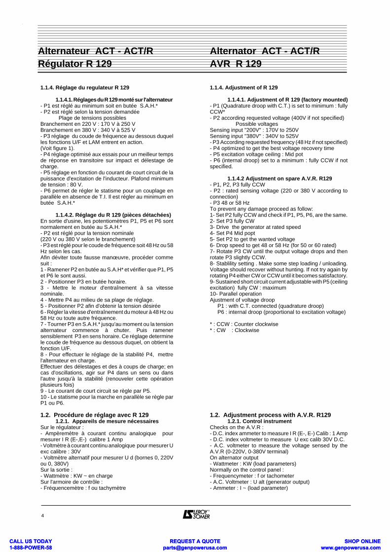
1.1.4. Réglage du regulateur R 129
1.1.4.1. Réglages du R 129 monté sur l'alternateur- P1 est réglé au minimum soit en butée S.A.H.*- P2 est réglé selon la tension demandée Plage de tensions possiblesBranchement en 220 V : 170 V à 250 VBranchement en 380 V : 340 V à 525 V- P3 réglage du coude de fréquence au dessous duquelles fonctions U/F et LAM entrent en action.(Voit figure 1).- P4 réglage optimisé aux essais pour un meilleur tempsde réponse en transitoire sur impact et délestage decharge.- P5 réglage en fonction du courant de court circuit de lapuissance d'excitation de l'inducteur. Plafond minimumde tension : 80 V.- P6 permet de régler le statisme pour un couplage enparallèle en absence de T.I. Il est régler au minimum enbutée S.A.H.*
1.1.4.2. Réglage du R 129 (pièces détachées)En sortie d'usine, les potentiomètres P1, P5 et P6 sontnormalement en butée au S.A.H.*- P2 est réglé pour la tension nominale (220 V ou 380 V selon le branchement)- P3 est réglé pour le coude de fréquence soit 48 Hz ou 58Hz selon les cas.Afin déviter toute fausse manœuvre, procéder commesuit :1 - Ramener P2 en butée au S.A.H* et vérifier que P1, P5et P6 le sont aussi.2 - Positionner P3 en butée horaire.3 - Mettre le moteur d'entraînement à sa vitessenominale.4 - Mettre P4 au milieu de sa plage de réglage.5 - Positionner P2 afin d'obtenir la tension désirée6 - Régler la vitesse d'entraînement du moteur à 48 Hz ou58 Hz ou toute autre fréquence.7 - Tourner P3 en S.A.H.* jusqu'au moment ou la tensionalternateur commence à chuter. Puis ramenersensiblement P3 en sens horaire. Ce réglage determinele coude de fréquence au dessous duquel, on obtient lafonction U/F.8 - Pour effectuer le réglage de la stabilité P4, mettrel'alternateur en charge.Effectuer des délestages et des à coups de charge; encas d'oscillations, agir sur P4 dans un sens ou dansl'autre jusqu'à la stabilité (renouveler cette opérationplusieurs fois)9 - Le courant de court circuit se règle par P5. 10 - Le statisme pour la marche en parallèle se règle parP1 ou P6.
1.2. Procédure de réglage avec R 1291.2.1. Appareils de mesure nécessaires
Sur le régulateur :- Ampèremètre à courant continu analogique pourmesurer I R (E-,E-) calibre 1 Amp- Voltmètre à courant continu analogique pour mesurer Uexc calibre : 30V - Voltmètre alternatif pour mesurer U d (bornes 0, 220Vou 0, 380V)Sur la sortie :- Wattmètre : KW ~ en chargeSur l'armoire de contrôle :- Fréquencemètre : f ou tachymètre
1.1.4. Adjustment of R 129
1.1.4.1. Adjustment of R 129 (factory mounted)- P1 (Quadrature droop with C.T.) is set to minimum : fullyCCW*- P2 according requested voltage (400V if not specified) Possible voltagesSensing input "200V" : 170V to 250VSensing input "380V" : 340V to 525V- P3 According requested frequency (48 Hz if not specified)- P4 optimized to get the best voltage recovery time- P5 excitation voltage ceiling : Mid pot- P6 (internal droop) set to a minimum : fully CCW if notspecified.
1.1.4.2 Adjustment on spare A.V.R. R129- P1, P2, P3 fully CCW- P2 : rated sensing voltage (220 or 380 V according toconnection)- P3 48 or 58 HzTo prevent any damage proceed as follow:1- Set P2 fully CCW and check if P1, P5, P6, are the same.2- Set P3 fully CW3- Drive the generator at rated speed4- Set P4 Mid popt5- Set P2 to get the wanted voltage6- Drop speed to get 48 or 58 Hz (for 50 or 60 rated)7- Rotate P3 CW until the output voltage drops and thenrotate P3 slightly CCW.8- Stablility setting . Make some step loading / unloading.Voltage should recover without hunting. If not try again byrotating P4 either CW or CCW until it becomes satisfactory.9- Sustained short circuit current adjustable with P5 (ceilingexcitation) fully CW : maximum10- Parallel operationAjustment of voltage droop P1 : with C.T. connected (quadrature droop) P6 : internal droop (proportional to excitation voltage)
* : CCW : Counter clockwise* : CW : Clockwise
1.2. Adjustment process with A.V.R. R1291.2.1. Control instrument
Checks on the A.V.R :- D.C. index ammeter to measure I R (E-, E-) Calib : 1 Amp- D.C. index voltmeter to measure U exc calib 30V D.C.- A.C. voltmeter to measure the voltage sensed by theA.V.R (0-220V, 0-380V terminal) On alternator output- Wattmeter : KW (load parameters)Normally on the control panel :- Frequencymeter : f or tachometer- A.C. Voltmeter : U alt (generator output)- Ammeter : I ~ (load parameter)
4
Alternator ACT - ACT/R AVR R 129
Alternateur ACT - ACT/R Régulator R 129
CALL US TODAY 1-888-POWER-58
REQUEST A QUOTE [email protected]
SHOP ONLINE www.genpowerusa.com
CALL US TODAY 1-888-POWER-58
REQUEST A QUOTE [email protected]
SHOP ONLINE www.genpowerusa.com

- Voltmètre alternatif : U alt (tension alternateur)- Ampèremètre : I ~ en chargeAutres :- Grippe - fils (mesure I R , U exc)
1.2.2. Branchements initiauxVérifier les connexions en se référant au schéma debranchement interne de la machine. Le transformateurde compoundage doit être branché suivant lesconnexions "100 %" (cf § 4 - 2 - 2). L'entrefer doit êtrefaible (0,5 mm) et équilibré.
1.2.3. Réglage à videFaire tourner l'alternateur à sa vitesse à vide(Voir tableau de décision )- Liste des actions et défauts - Noter les valeurs IRØ du courant dérivé par lerégulateur et U ExcØ de la tension d'excitation à vide.
1.2.4. Réglage en charge(L'alternateur est supposé avoir èté réglé à vide à UN)- Faire tourner l'alternateur à sa vitesse nominale à vide.- Noter les valeurs IRØ .- Si la charge nominale n'est pas disponible appliquer unecharge suffisamment importante (≥ 30 % Sn) et inductive(cos Ø ≤ 0,9 AR).- Noter les valeurs de tensions aux bornes de l'alternateur(U alt C), du courant dérivé (IRC) et de la tensiond'excitation (U excC).(Voir tableau de décision )
1.2.5. FonctionnementLe régulateur est capable de dériver 4 A en continu et 10A en pointe : le courant dérivé est haché et la puissancedissipée ne dépasse pas 50 W.Le moyen de contrôler l'action du régulateur est demesurer le courant (I R) dérivé par le régulateur et latension (U exc) d'excitation (bornes E+,E- du régulateur).Utiliser des appareils de mesure continu (cal = 1-3 A et 30 V) à galvanomètre pour mesures de tensions etcourants hachées.
Other :- Gripping clips (measurement of I R , U exc)
1.2.2. Initial tappingsCheck connections by refering to the internal connectiondiagram of the machine. The secondaries of compoundingtransformer must be tapped "100 %" (see § 4 - 2 - 2). The airgap must be weak (ab. 0,5 mm) and shared.
1.2.3. Adjustment at no loadDrive the alternator at rated speed(See diagnosis chart )- Listing of actions and faults.- Record the values IRØ of the diverted current and U exc Øof the excitation voltage
1.2.4. Adjustment with load(The alternator is supposed to have been adjusted at noload at UN)- Drive the alternator at rated speed, no load.- Record the values of current (IRØ) - If the rated load is not available, apply a sufficient ( ≥ 30 % Sn) and inductive (P.F ≤ 0,9 LAG) load- Record the voltages across alternator terminal (U altC)the diverted current (IRC), and exciter field voltage (UexcC) - (See diagnosis chart )
1.2.5. Operation
The A.V.R may divert 4 A continuously and 10 A peak : thediverted current is chopped and the heat rejection is lessthan 50 Watt. The way to check the proper operation ofvoltage regulator is to measure current (IR) diverted byA.V.R. and the excitation voltage (U exc) (terminals E+ andE- of A.V.R). Use analogical moving coil meters (cal 1-3 Aand 30 v - DC) to measure chopped voltages/currents.
5
Alternator ACT - ACT/R AVR R 129
Alternateur ACT - ACT/R Régulator R 129
Conditions normalesde réglageNormal adjustment
20
Tension d'excitationExcitation Voltage
6U exc Ø
0
U excC
U exc (E+,E-)
CosØ =1
CosØ = 0,8I R (E-,E-)
I R C
(Test conditions)S/SN
Charge / Load100 %
CosØ = 0,8
CosØ =1
U exc
0,25
1A
I R Courant dérivé Diverted current
I R Ø
CALL US TODAY 1-888-POWER-58
REQUEST A QUOTE [email protected]
SHOP ONLINE www.genpowerusa.com
CALL US TODAY 1-888-POWER-58
REQUEST A QUOTE [email protected]
SHOP ONLINE www.genpowerusa.com

Pour un réglage correct et dans les conditions normalesde fonctionnement du compound, le rapport Uexc/Ir, àvide ou en charge doit être compris entre 20 et 30(réglage usine 25) exemple :
I R = 0 signifie que le régulateur ne dérive rien : a) - Excitation compound insuffisante b) - Réglage tension trop haut (régulateur)Uexc/Ir < 5 signifie que le régulateur ne peut pas dériverdavantage : a) - Excitation compound trop forte b) - Réglage tension trop bas (régulateur)
1.3. Vérification statique du régulateur R 129 seul-Relier la detection de tension (bornes 0V -220V, or 0V-380V suivant la tension) à un réseau alternatif- Raccorder une batterie avec une lampe en série L2comme indiqué . - Raccorder une lampe en série L1 en sortie E+, E- du ré-gulateur . - Tourner le potentiomètre tension (P2) de la position "àfond à droite" à la position "à fond à gauche", puis denouveau "à fond à droite": La lampe doit s'allumer puiss'éteindre- Si la lampe L1 reste toujours allumée ou toujourséteinte, quelque soit la position du potentiomètre, lerégulateur est défectueux.La lampe L2 doit toujours rester allumée.* Nota : Attendre quelque secondes (10 à 30) l'allumageou l'extinction de la lampe.
In normal operation conditions and for a proper adjustmentof compound system, the ratio Uexc/Ir on load or no load,must be between 20 and 30 ( factory adjustment about 25) i.e.
I R = 0 means that the regulator diverts nothing : a) - Compound set too low b) - Voltage adjusted too high (regulator)Uexc/Ir< 5 means that the regulator cannot divert anymore : a) - Compound set too high b) - Voltage adjusted too low (regulator)
1.3. Static check of the voltage regulator R 129 single- Connect the voltage sensing (terminals 0V -220V,or 0V380V according to voltage) to the A.C. mains- Connect a battery with a lamp L2 in series as shown hereafter .- Connect a lamp L1 on output E+, E- of the A.V.R.- Turn the voltage potentiometer (P2) from "fully clockwise"to "fully anticlockwise", then in the reverse direction.- The lamp must brighten then dim.- If the lamp remains bright or unlit whatever the position ofpot (P2), that means that the regulator is defective.Lamp L2 must always be lit.* Note : Wait for 10 ...30 seconds the lamp lighting on or off
6
Alternator ACT - ACT/R AVR R 129
Alternateur ACT - ACT/R Régulator R 129
Inducteur / Exciter fieldE+ E-+RED
+E-ES2S1
0
220380
10
9
8
7
6
5
4
3
2
1
+
-V
+
- A+ -
Uexc (30V-D.C.)I r (1A-D.C.)
V Ud (300-500V - A.C.)
Sensing
R 129
Pont redresseurRectifier bridge
Compound
~~~
IR (A) U exc (V) U exc /Ir U alt (V) FREQUENCE (Hz)
à vide 0,22 - 0,33 6,5 20.....30 400 51,5 no laden charge 0,73 - 1,1 22 20.....30 400 50 on load
Tension Voltage 470 - 1W R-03
+RED+E-ES2S1
0
220380
P4
P6
P3
P2
P5P1
R 129
J2
-+
Batterie / Battery ; 12 ........48 V
L1 . Lampe - Lamp : 12 .......48 V
360 ....500 V180 .....250 V
RéseauMains
Dans le cas d'un potentiomètre extérieur - Court-circuiter les bornes J2If remote trimmer was used - Short terminals J2
L2 . Lampe - Lamp : 12 .......48 V
P2 P2
L2
L1
L2
L1
U
CALL US TODAY 1-888-POWER-58
REQUEST A QUOTE [email protected]
SHOP ONLINE www.genpowerusa.com
CALL US TODAY 1-888-POWER-58
REQUEST A QUOTE [email protected]
SHOP ONLINE www.genpowerusa.com
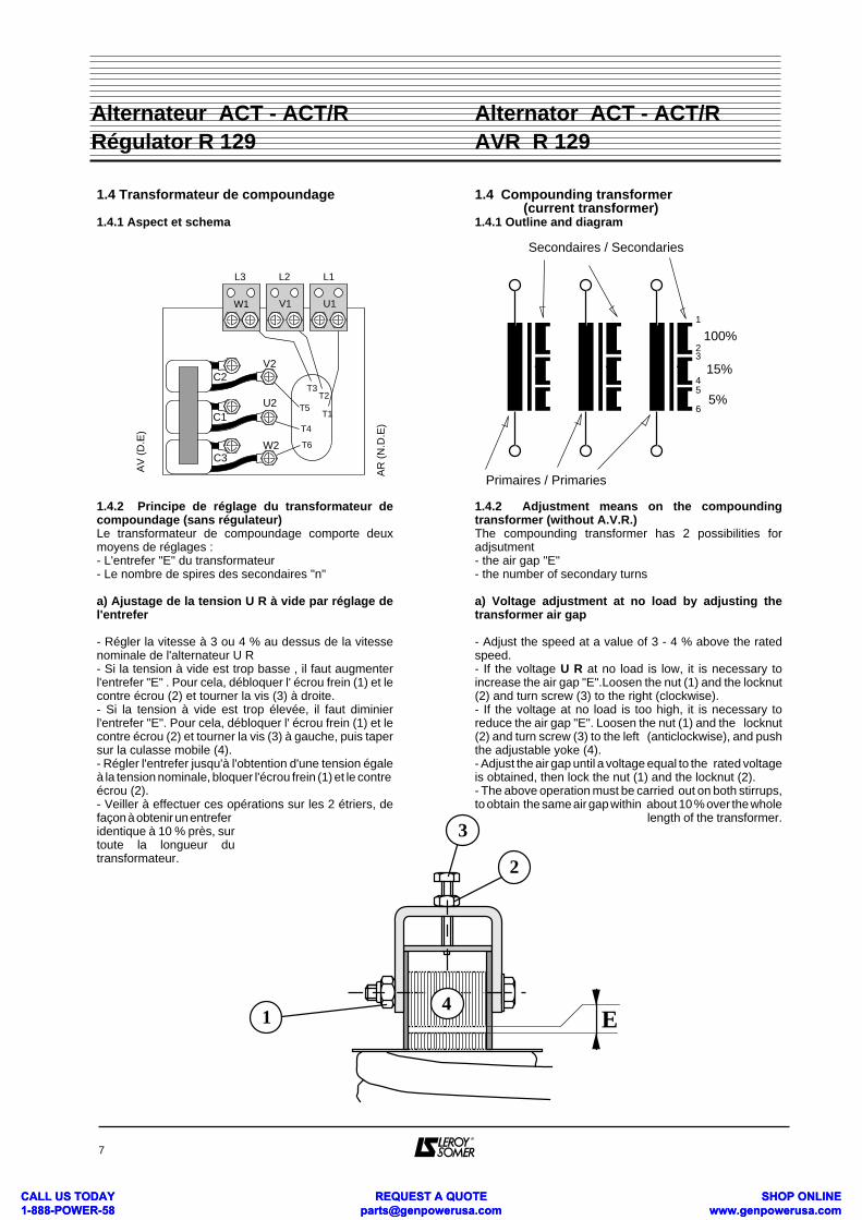
1.4 Transformateur de compoundage
1.4.1 Aspect et schema
1.4.2 Principe de réglage du transformateur decompoundage (sans régulateur)Le transformateur de compoundage comporte deuxmoyens de réglages :- L'entrefer "E" du transformateur- Le nombre de spires des secondaires "n"
a) Ajustage de la tension U R à vide par réglage del'entrefer
- Régler la vitesse à 3 ou 4 % au dessus de la vitessenominale de l'alternateur U R- Si la tension à vide est trop basse , il faut augmenterl'entrefer "E" . Pour cela, débloquer l' écrou frein (1) et lecontre écrou (2) et tourner la vis (3) à droite.- Si la tension à vide est trop élevée, il faut diminierl'entrefer "E". Pour cela, débloquer l' écrou frein (1) et lecontre écrou (2) et tourner la vis (3) à gauche, puis tapersur la culasse mobile (4).- Régler l'entrefer jusqu'à l'obtention d'une tension égaleà la tension nominale, bloquer l'écrou frein (1) et le contre écrou (2).- Veiller à effectuer ces opérations sur les 2 étriers, defaçon à obtenir un entreferidentique à 10 % près, surtoute la longueur dutransformateur.
1.4 Compounding transformer (current transformer)1.4.1 Outline and diagram
1.4.2 Adjustment means on the compoundingtransformer (without A.V.R.)The compounding transformer has 2 possibilities foradjsutment- the air gap "E"- the number of secondary turns
a) Voltage adjustment at no load by adjusting thetransformer air gap
- Adjust the speed at a value of 3 - 4 % above the ratedspeed.- If the voltage U R at no load is low, it is necessary toincrease the air gap "E".Loosen the nut (1) and the locknut(2) and turn screw (3) to the right (clockwise).- If the voltage at no load is too high, it is necessary toreduce the air gap "E". Loosen the nut (1) and the locknut(2) and turn screw (3) to the left (anticlockwise), and pushthe adjustable yoke (4). - Adjust the air gap until a voltage equal to the rated voltageis obtained, then lock the nut (1) and the locknut (2).- The above operation must be carried out on both stirrups,to obtain the same air gap within about 10 % over the whole
length of the transformer.
7
Alternator ACT - ACT/R AVR R 129
Alternateur ACT - ACT/R Régulator R 129
T3T2
T1
T4
T6
T5
AV
(D
.E)
AR
(N
.D.E
)
C1
C2
C3
U2
V2
W2
W1 V1 U1
L1L2L3
Primaires / Primaries
1
23
45
6
Secondaires / Secondaries
100%
15%
5%
1
2
3
E4
CALL US TODAY 1-888-POWER-58
REQUEST A QUOTE [email protected]
SHOP ONLINE www.genpowerusa.com
CALL US TODAY 1-888-POWER-58
REQUEST A QUOTE [email protected]
SHOP ONLINE www.genpowerusa.com
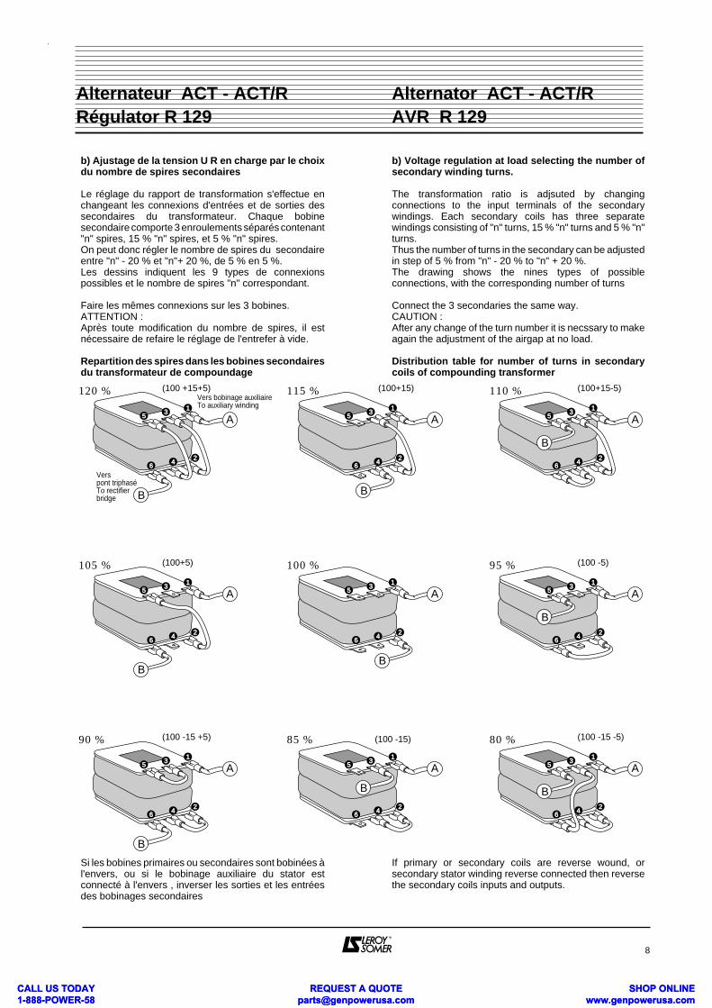
b) Ajustage de la tension U R en charge par le choixdu nombre de spires secondaires
Le réglage du rapport de transformation s'effectue enchangeant les connexions d'entrées et de sorties dessecondaires du transformateur. Chaque bobinesecondaire comporte 3 enroulements séparés contenant"n" spires, 15 % "n" spires, et 5 % "n" spires.On peut donc régler le nombre de spires du secondaireentre "n" - 20 % et "n"+ 20 %, de 5 % en 5 %.Les dessins indiquent les 9 types de connexionspossibles et le nombre de spires "n" correspondant.
Faire les mêmes connexions sur les 3 bobines.ATTENTION :Après toute modification du nombre de spires, il estnécessaire de refaire le réglage de l'entrefer à vide.
Repartition des spires dans les bobines secondairesdu transformateur de compoundage
Si les bobines primaires ou secondaires sont bobinées àl'envers, ou si le bobinage auxiliaire du stator estconnecté à l'envers , inverser les sorties et les entréesdes bobinages secondaires
b) Voltage regulation at load selecting the number ofsecondary winding turns.
The transformation ratio is adjsuted by changingconnections to the input terminals of the secondarywindings. Each secondary coils has three separatewindings consisting of "n" turns, 15 % "n" turns and 5 % "n"turns.Thus the number of turns in the secondary can be adjustedin step of 5 % from "n" - 20 % to "n" + 20 %.The drawing shows the nines types of possibleconnections, with the corresponding number of turns
Connect the 3 secondaries the same way.CAUTION :After any change of the turn number it is necssary to makeagain the adjustment of the airgap at no load.
Distribution table for number of turns in secondarycoils of compounding transformer
If primary or secondary coils are reverse wound, orsecondary stator winding reverse connected then reversethe secondary coils inputs and outputs.
8
Alternator ACT - ACT/R AVR R 129
Alternateur ACT - ACT/R Régulator R 129
115 % 110 % (100+15-5)120 %Vers bobinage auxiliaireTo auxiliary winding
Vers pont triphaséTo rectifier bridge
(100 +15+5)
B
A1
35
24
6
B
A1
35
24
6
B
A1
35
24
6
100 % 95 %
(100+15)
(100 -5)105 % (100+5)
B
A1
35
24
6
B
A1
35
24
6
B
A1
35
24
6
85 % 80 %(100 -15) (100 -15 -5)90 % (100 -15 +5)
B
A1
35
24
6
B
A1
35
24
6
B
A1
35
24
6
CALL US TODAY 1-888-POWER-58
REQUEST A QUOTE [email protected]
SHOP ONLINE www.genpowerusa.com
CALL US TODAY 1-888-POWER-58
REQUEST A QUOTE [email protected]
SHOP ONLINE www.genpowerusa.com

TABLEAU DE DECISION DIAGNOSIS CHART
9
Alternator ACT - ACT/R AVR R 129
Alternateur ACT - ACT/R Régulator R 129
Réglage à vide / Adjustment at no load
I R Ø - DC AMPCasCase U alt < 0,10A 0,2-0,4 A > 0,5A
1 ~ 0 A1 N N
2 5 - 15 % UN F1 F2 N
3 40 - 60 % UN F3/F7 F4 F4 / F7
4 70 - 90 % UN A2/F7 A3 A3
5 95 - 100 % UN A2 A3 A3 + A4
6 UN (± 1 %) A2 A5 A4
7 100 - 105 % UN A3 + A2 A3 A3 + A4
8 110 - 115 % UN F5 A3 +A4 A4 + A3
9 120 - 135 % UN F5 F6 F6
10OscillationsHunting A6 A6/F12 A6/F12
Symboles SymbolsTension nominale altern. UN Alternator rated voltage
Action à entreprendre A Action to be made
Défauts F Fault to be cleared
Impossible (tout vérifier) N Impossible (check again)
ou / or
et + and
supèrieur à a > b more than
supèrieur ou égal à a ≥ b equal or more than
beaucoup supérieur a >> b much more than
inférieur à a < b less than
inférieur ou égal a ≤ b equal or less
beaucoup inférieur a << b much less than
compris entre > a > between
Réglage en charge Adjustment with load U excC ≤ U exc Ø U excC >>U exc Ø
Cas U alt I RC ≤ I RØ I RC >>I RØ
Case I RC - DC AMP r = U excc / IRc
< 0,1 A > 0,2 A r > 30 20 ≤ r≤ 30 r< 20
1 0 - 94 % UN F3 A7 + F11 F2 A7 + F11 F2 F2
2 94 - 98 % UN N A7 + F11 A7+F9+F10 A7+F10+F11 F9+F10 A8+F9+F10
3 98 - 102 % UN N A7 A7 A7 OK A8
4 102 - 106 % UN N F2+A7+F9 A7+F9+F10 A7+F9 F9+F10 A8+F10+F11
5 > 106 % UN N F5 F2 F2 F2 A8+F11
6 Oscillations Hunting - A7 A7 A6/F12 A6/F12 A6/F12
+ F8 + F3
CALL US TODAY 1-888-POWER-58
REQUEST A QUOTE [email protected]
SHOP ONLINE www.genpowerusa.com
CALL US TODAY 1-888-POWER-58
REQUEST A QUOTE [email protected]
SHOP ONLINE www.genpowerusa.com

Actions :
A1 : Amorcer à l'aide d'une batterie ( cf § 7 - 6 )A2 : Augmenter l'entrefer du transformateur decompoundage (cf § 4 - 2)A3 : Régler la tension - sur le régulateur : potentiomètre (P2) - ou potentiomètre extérieurA4 : Diminuer l'entrefer du transformateur decompoundage (cf § 4 - 2)A5 : Réglage final à vide. I R doit être compris entre 0,2 et 0,4 A et le rapport Uexc/IR doit être compris entre 20 et 30 - Si Uexc/IR > 30 = A2 - Si Uexc/IR < 20 = A4A6 : Régler la stabilité à l'aide du potentiomètre (P4) Nota : Le pompage peut être causé par des variations de vitesse (injecteurs ou régulateur de vitesse défectueux)A7 : Couper la charge et arrêter le groupe - Diminuer le nombre de spires secondaires sur le transformateur de compoundage (cf § 4 - 2) - Redémarrer et refaire le réglage à videA8 : Couper la charge et arrêter le groupe - Augmenter le nombre de spires secondaires sur le transformateur de compoundage (cf § 4 - 2) - Redémarrer et refaire le réglage à vide
Défauts :
F1 : Circuit d'excitation coupéF2 : Défaut régulateurF3 : Défaut diodes tournantes, ou pont redresseur ou induit d'excitatriceF4 : Détection de tension mal branchée F5 : Régulateur non ou mal connecté ou en défautF6 : Transformateur de compoundage mal raccordé(bobine 100 % non raccordé) ou en court circuit, ou maladapté (rechange)F7 : Mauvais couplage du bobinage principal.F8 : Transformateur de compoundage mal raccordé ouen court circuit, ou mal adapté (rechange)F9 : Statisme interne ou satisme par T.I. en action. Tourner les potentiomètres P1 et P6 à fond à gaucheF10 : La charge est déformante (ex: redresseurs, onduleurs)F 11 : Mauvais raccordement du transformateur decompoundage (non en phase). Vérifier les phases dubobinage auxiliaire par rapport au compound F 12 : Action intempestive du LAMVérifier la fréquence - Règler le seuil V/Hz P3.
O K : Réglage correct
Actions :
A1 : Flash the field with a battery (see § 7 - 6 )A2 : Increase airgap of compounding transformer (see § 4 - 2)A3 : Adjust voltage - On the regulator, with pot (P2) - Or with remote voltage trimmerA4 : Decrease airgap of compounding transformer (see § 4 - 2)A5 : Final no load adjustment. I R must be between 0,2 and 0,4 A and the ratio Uexc/IR must be comprised between 20 and 30 - If Uexc/IR > 30 = A2 - If Uexc/IR < 20 = A4A6 : Adjust Stability with pot (P4) on voltage regulator Note : Hunting may also be due to speed variations (defective injector or governor)A7 : Switch the load off and stop the genset - Decrease the number of secondary turns on the compounding transformer as indicated see § 4 - 2 - Restart and proceed to adjustment at no loadA8 : Switch the load off and stop the genset - Increase the number of secondary turns on the compounding transformer as indicated see § 4 - 2 - Restart and proceed to adjustment at no load
Faults :
F1 : Excitation circuit opened.F2 : Voltage regulator defectiveF3 : Failure in rotating diodes, rectifier bridge or exciter armatureF4 : Voltage sensing wrongly connected F5 : Voltage regulator either wrongly or not connected or defectiveF6 : Compounding transformer wrongly connected (100%coil not in circuit) or in short circuit, or not adapted (wrongspare part)F7 : Bad connection of stator winding (terminal board).F8 : Compounding transformer wrongly connected or inshort circuit, or not adapted (wrong spare part)F9 : Internal droop or quadrature droop acting - Turn potentiometers P1 and P6 fully anticlockwiseF10 : The load is probably distorting (i.e. : rectifier, inverter)F11 : Wrong connection of auxiliary winding tocompounding transformer . Check phase relation shipbetween auxiliary winding and compounding transformerprimaries.F 12 : Undue action of LAM. Check frequency Readjust V/Hz P3.
O K : Adjustment is correct
10
Alternator ACT - ACT/R AVR R 129
Alternateur ACT - ACT/R Régulator R 129
CALL US TODAY 1-888-POWER-58
REQUEST A QUOTE [email protected]
SHOP ONLINE www.genpowerusa.com
CALL US TODAY 1-888-POWER-58
REQUEST A QUOTE [email protected]
SHOP ONLINE www.genpowerusa.com

1.5. Marche en parallèle
1.5.1. Avec régulateur R 129Consulter l'usine
1.5.2. Marche en parallèle permanente avec le réseauavec régulateur de Cos Ø additionnel R 725Demander la notice correspondante
1.5.3. Marche en parallèle permanente avec leréseau, utiliser les régulateurs série R 200Demander la notice correspondante
1.6. REGLAGES DU SYSTEME D'EXCITATIONSANS REGULATEUR AVEC RHEOSTAT (MARCHE EN MANUEL)Les réglages de base du système compound se font pourla tension nominale U N correspondant au type dubobinage : par exemple pour le bobinage 1 couplage D latension nominale est 400 V à 50 Hz et 480 V à 60 HzNota : sans régulateur, la tension de l'alternateur variecomme la vitesse.
1.6.1. Description de l'action du rhéostatLe rhéostat est branché en parallèle sur les inducteurs del'excitatrice. Il est en série avec une résistance talon de20 Ohms.Il comporte 3 secteurs de section différente.La position 0 correspond à "à fond à gauche" et 4/4 "àfond à droite" vu de l'axe de commande.
L'équivalent de ce rhéostat en résistance réglable ourhéostat à section constante est de 180 Ohms - 180 Watt(1A)ActionLe rhéostat dérive une partie du courant d'excitationproduit par le système compound.- La tension de l'alternateur augmente quand on tourne lerhéostat vers la droite.- Pour une même variation de la résistance, le rhéostat abeaucoup plus d'action sur la tension en charge que surla tension à vide:la tension à vide ne doit pas être réglée en agissant sur lerhéostat, mais sur l'entrefer du transformateur decompoundage .
1.5. Parallel operation
1.5.1. With regulator R 129Consult factory
1.5.2. Continuous operation in parallel with the mainswith additionnal P.F. regulator R 725Ask for relevant handbook
1.5.3. Continuous operation in parallel with the mainsenable use of regulators of range R200Ask for relevant handbook
1.6. EXCITATION SYSTEM ADJUSTMENTWITHOUT REGULATOR (FAIL SAFE OPERATION)The basic adjustment on the compounding excitationsystem have to be made for the rated voltage U Ncorresponding to the winding type : i e for winding nr 1,connection D (series Star) the rated voltage is 400 V at 50Hz and 480 V at 60 Hz.Note : Without A V R, the alternator's output voltage variesas the speed.
1.6.1. Description of the rhéostat actionThe rhéostat is connected in parallel with the exciter field. Itis in series with a limiting resistor of 20 Ω and is divided in 3sections of different cross section conductorPosition 0 - fully anticlockwisePosition 4/4 - fully clockwiweSeen from the setting side
The equivalent of this rheostat is an adjustable resistor, orconstant cross section rheostat of 180Ω - 180 Watt (1A)ActionThe rheostat diverts one part of the excitation currentsupplied by the compounding system- The output voltage of the generator increase when therheostat is rotated clockwise.- For the same variation of the resistance, the rheostat hasmuch more action on the voltage on load than at no load: theno load voltage is not be adjusted with the rheostat, but byadjusting the air gap of the compounding transformer.
11
Alternator ACT - ACT/R AVR R 129
Alternateur ACT - ACT/R Régulator R 129
20 Ω
100 Ω
20 ΩRésistance totaleTotal resistance
i max = 1 A
0
1/3
1/2
2/3
4/4
Résistance talonLimiting resistor
0
1/3
1/2
2/3
4/4
20 Ω
40 Ω
60 Ω
80 Ω
180 Ω
Position Résistance totaleTotal resistance
40 Ω
CALL US TODAY 1-888-POWER-58
REQUEST A QUOTE [email protected]
SHOP ONLINE www.genpowerusa.com
CALL US TODAY 1-888-POWER-58
REQUEST A QUOTE [email protected]
SHOP ONLINE www.genpowerusa.com

1.6.2. Organigramme de réglage du systèmed'excitation compound sans régulateur avecrhéostatVoir tableau page 26 pour les conditions de réglageU T : Tension aux bornes de l'alternateur indiquée dans letableau.U A : Tension alternateurA l'arrêt1) Raccorder les câbles de puissance suivant le schémade branchement2) Régler le rhéostat à 40 ou 60 Ω suivant les conditionsde charge (tableau page )3) Débloquer la culasse du transformateur decompoundage (page 19) pour pouvoir régler l'entrefer enmarche.4) Connecter les secondaires du transformateur decompoundage suivant le branchement 100 % (page 20)5
1.6.2. Adjustment procedure of the compoundexcitation system without AVR. with a rheostatSee table page 26 for testing conditions.U T : Output voltage of generator indicated in tableU A : Alternator's output voltagePreliminary :1) Connect power cable according to relevant diagram2) Preset the rheostat to 40 or 60 Ω according to the loadconditions (see table page )3) Loosen the yoke of the compounding transformer (seepage 19) to enable adjustment of air gap when running4) Connect the secondaries of the compoundingtransformer according to the 100 % tapping (see table page20).
12
Alternator ACT - ACT/R AVR R 129
Alternateur ACT - ACT/R Régulator R 129
Démarrer le groupe électrogène - Régler la vitesse pour obtenir à vide 52 ou 63 Hz (ou la fréquence nominale à vide)Start the gen set - Adjust speed to get at no load 52 or 63 Hz (or the real no-load frequency)
A vide - No load : F = 52 ou/or 63 Hz
U A < U T U A = U T U A - 1,3 U T~
Augmenter l'entreferIncrease air gap
Si impossibleIf impossible
Erreur compound ,défaut des diodes tournantes ou pont redresseurWrong compound transformer or failures (diodes, rectifier bridge)
Diminuer l'entreferDecrease air gap
Si impossibleIf impossible
U A > U T STOP
Erreur de branchement du compound ou défaut (court-circuit) transfo de compoundageWrong connection to compound transformer or short in secondary
Appliquer la charge - Régler la vitesse / Apply the load - Adjust speed
En charge : F = 50 ou 60 Hz (quelques minutes de fonctionnement)On load : F = 50 ou 60 Hz (some minutes operation)
U A > U T
STOP
U A = U T
La tension de l'alter- nateur est très basseVoltage is very low
Diminuer le nombre de spires secondaire de 5 %Decrease number of secondary turns by 5 %
U A < U T
STOP
Erreur de branchement du compound Permuter les entrées et les sorties des secondaires. Repérer les phases Wrong connection of compound transformer. Check phase position. Transpose input and output of secondaries
La tension de l'alter- nateur est très élevéeVoltage is very high
Erreur de branchement du compound. Repérage des phases Wrong connection of compounding transformer. Check phase position.
Augmenter le nombre de spires secondaire de 5 %Increase number of secondary turns by 5 %
Si impossibleIf impossibleSi impossible
If impossible
Délester la charge - Switch off the load
REGLAGE TERMINE - Bloquer la culasse du transformateur de compoundage, à vide en maintenant UA = UTFINISHED ADJUSTMENTS - No load . Tighten the yoke of compounding transformer, taking care that UA remains equal to UT
Redémarrer / Start again Redémarrer / Start again
CALL US TODAY 1-888-POWER-58
REQUEST A QUOTE [email protected]
SHOP ONLINE www.genpowerusa.com
CALL US TODAY 1-888-POWER-58
REQUEST A QUOTE [email protected]
SHOP ONLINE www.genpowerusa.com

1.6.3. Consignes de réglagesPour régler le système d'excitation compound, lerhéostat doit être amené à une position fixe qui dépendde la charge disponible pour le réglage et des conditionsfinales d'utilisation.- Si la charge dont on dispose pour faire les essaisconsomme suffisamment d'énergie réactive (Cos. Ø 0,6à 0,95 AR), c'est-à-dire si elle est constituée de moteursélectriques et que l'utilisation sur le site a aussi lesmêmes caractéristiques : voir ligne A du tableau ci-dessous (conditions de réglage usine)- On ne dispose pour faire les réglages que d'une chargeà Cos Ø =1 (résistance liquide par exemple) alors que lacharge sur le site est à Cos Ø entre 0,6 et 0,95 AR : Voirligne B- Les réglages et l'utilisation sur le site sont à Cos Ø : 1 voirligne C- Si l'installation comporte des batteries de condensa-teurs pour la compensation globale du Cos Ø et qu'à unmoment donné ces condensateurs se trouvent seulsalimentés par l'alternateur, il faut absolumentdébrancher les batteries de condensateur en servicesecours sur groupe électrogène car la tension del'alternateur devient incontrôlable.
* Régler la vitesse pour obtenir 50 Hz ou 60Hz en charge,la fréquence à vide indiquée doit être remplacée par lafréquence réelle à vide
1.6.4. Réglages de tension à l'utilisation (sur lesite)Les réglages sur le site se font à l'aide du rhéostat qui :- permet de fonctionner à une tension différente de latension réglage.- permet de s'adapter au Cos Ø réel de l'installation saufpour Cos Ø 1 - voir réglage spécial- permet de s'adapter au statisme réel du diesel- permet de compenser les variations dues àl'échauffement.
1.6.3. Adjustment instructions with a rheostatTo enable the proper adjustment of the compound system,the rheostat is preset to a fixed position (value) dependingupon the load available for testing and the final conditionson site- If the load available for testing is consuming enoughreactive power (p.f. 0,6 to 0,95 LAG ) being made up ofelectric motors, chokes,..... and the site load conditions arethe same, see line A of the following table (factoryadjustments).- If the only available testing load is a p.f. :1 (i.e. liquidresistor tank) and, on site, the load is at p.f. 0,6 to 0,95 LAG,see line B.- If for testing and on site the p.f. : 1 see line C- If on site, the p.f. of the plant is corrected with capacitorsand it could happen that at any moment only thesecapacitors are supplied by the alternator it is absolutelynecessary to disconnect the capacitors otherwise thevoltage generator raises or drops helplessly.
* Adjust no- load speed so that to get 50 ou 60 Hz on load.The indicated no-load frequency must be replaced by thetrue no-load frequency
1.6.4. Voltage adjustment on siteVoltage adjustments on site are made with the rheostatwhich allows- Operation at a voltage different to the factory - set - voltage- Adaption to the real power factor of the consumers (exceptfor p.f. :1, see special adjustment advice)- Adaption to the real speed droop of the engine- Compensation for the variation in voltage due totemperature rise.
13
Alternator ACT - ACT/R AVR R 129
Alternateur ACT - ACT/R Régulator R 129
VALEURS A FROID - VALUES WHEN COLD
U T : Tension à obtenir Voltage to be obtained RheostatCharges - load
Réglages - TestCos Ø
Site - SiteCos Ø
A vide No load
En charge On load
Valeurs de réglageon test
Ohm (position)
SiteOn site
Ohm (position)
0,6 à 0,95AR/LAG
0,6 à 0,95AR/LAG
0,6 à 0,95AR/LAG
A
B
C
1
1 1
Fréquences
Frequencies
52 Hz*
63 Hz*
50 Hz
60 Hz
U N(400 V)
U N +2,5%(410 V)
U N +2,5%(410 V)
U N +2,5%(410 V)
U N -2,5%(390 V)
U N(400 V)
60 (1/2)
40 (1/3)
60 (1/2)
60 (1/2)
40 (1/3) 40 (1/3)
CALL US TODAY 1-888-POWER-58
REQUEST A QUOTE [email protected]
SHOP ONLINE www.genpowerusa.com
CALL US TODAY 1-888-POWER-58
REQUEST A QUOTE [email protected]
SHOP ONLINE www.genpowerusa.com

1.7. Repérage des phases du bobinageauxiliaire par rapport aux phases du statorLes essais pour repérer les phases du bobinageauxiliaire par rapport aux phases du stator, se font,l'alternateur fonctionnant à vide, le stator étant couplé enétoile.- Réaliser un neutre artificiel en branchant 3 résistancesde 220 Ω - 10 W couplées en étoile, aux bornes dubobinage auxiliaire.- Relier comme indiqué dans le schéma page 35, leneutre de l'alternateur au neutre artificiel du bobinageauxiliaire- Mesurer et noter les tensions : UPHN entre phase et neutre du bobinage stator uphn entre phase et neutre du bobinage auxiliaire U1, U2, U3, V1, V2, V3, W1, W2 et W3 entre les sortiesdu bobinage principale UVW et les sorties du bobinageauxiliaire marquées pour l'essai 1,2,3.
Supposons que UPHN = 220 V et que uphn = 22 VLes résultats des mesures peuvent se présenter sousforme de 2 tableaux différents A ou B.- Le tableau A contient 3 valeurs de tension égales à220 - 22 = 198 Volts et6 valeurs égales à 220 + (22 x 0,45) = 230 Volts
- Le tableau B contient 3 valeurs de tension égales à220 + 22 = 242 Volts et6 valeurs égales à 220 - (22 x 0,45) = 210 Volts
1.7. Identification of auxiliary winding phases inrelation to stator phasesThe tests to identify the auxiliary winding phases in relationto the stator winding phases are carried out, with the statorstar coupled.- Make an artificial neutral by connecting 3 resistors (220 Ω,10 W) in star, to the output terminals of the auxiliary winding.- Connect the circuit as shown in the diagram below, withthe alternator neutral connected to the auxiliary windingartificial neutral.- Measure and note the following voltages : Uphn between phase and neutral of the stator winding Uphn between phase and neutral of the auxiliary winding. U1, U2, U3, V1, V2, V3, W1, W2 and W3 , between themain winding outputs UVW and the auxiliary windingoutputs marked 1,2,3 for check purpose.
Assume that UPHN = 220 V and that uphn = 22 VThe resulting measurements may be presented in twodifferent forms of table, A or B.- Table A contains 3 voltage values equal to 220 - 22 = 198 Voltsand 6 values equal to 220 + (22x0,45) = 230 Volts
- Table B contains 3 voltage values equal to 220 + 22 = 242 Voltsand 6 values equal to 220 - (22x0,45) = 210 Volts
14
Alternator ACT - ACT/R AVR R 129
Alternateur ACT - ACT/R Régulator R 129
T3T2
T1
T4
T6
T5C1
C2
C3
U2
V2
W2
W1 V1 U1
N
L1L2L3
220 Ω - 10 W
220 Ω - 10 W
220 Ω - 10 W
Vuphn
VU-1
VUPHN
Vers bobinages auxiliairesTo auxiliary winding
Neut
re a
rtific
iel
Artif
icial
neu
tral
Connexions étoile série (Code D)Series star connection (Code D)
Phase du bobinage principal
Main winding phase U V W
1 198 230 230 1 = U
Marquage du bob.auxiliaire 2 230 230 198 2 = W
Aux. winding ident. marking 3 230 198 230 3 = V
Phase du bobinage principal
Main winding phase U V W
1 210 242 210 1 = V
Marquage du bob.auxiliaire 2 242 210 210 2 = U
Aux. winding ident. marking 3 210 210 242 3 = W
CALL US TODAY 1-888-POWER-58
REQUEST A QUOTE [email protected]
SHOP ONLINE www.genpowerusa.com
CALL US TODAY 1-888-POWER-58
REQUEST A QUOTE [email protected]
SHOP ONLINE www.genpowerusa.com
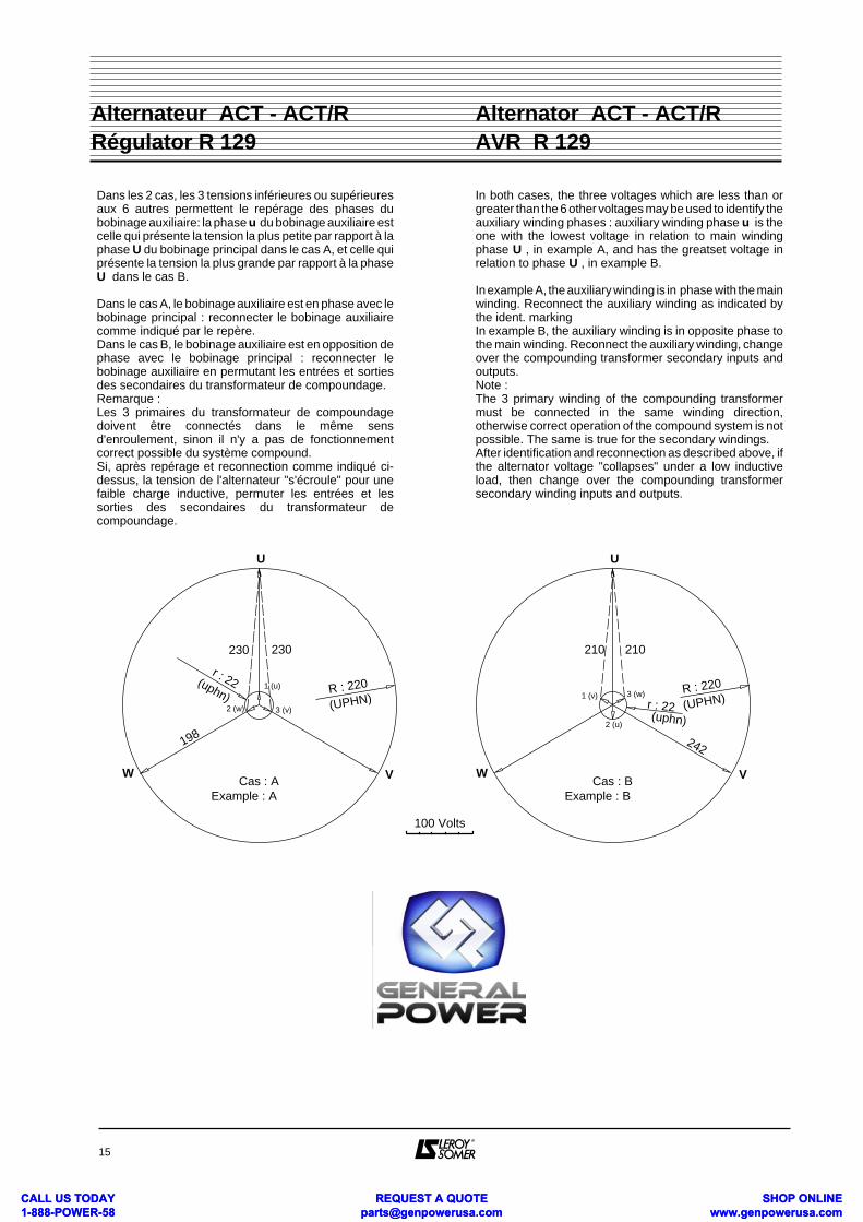
Dans les 2 cas, les 3 tensions inférieures ou supérieuresaux 6 autres permettent le repérage des phases dubobinage auxiliaire: la phase u du bobinage auxiliaire estcelle qui présente la tension la plus petite par rapport à laphase U du bobinage principal dans le cas A, et celle quiprésente la tension la plus grande par rapport à la phaseU dans le cas B.
Dans le cas A, le bobinage auxiliaire est en phase avec lebobinage principal : reconnecter le bobinage auxiliairecomme indiqué par le repère.Dans le cas B, le bobinage auxiliaire est en opposition dephase avec le bobinage principal : reconnecter lebobinage auxiliaire en permutant les entrées et sortiesdes secondaires du transformateur de compoundage.Remarque :Les 3 primaires du transformateur de compoundagedoivent être connectés dans le même sensd'enroulement, sinon il n'y a pas de fonctionnementcorrect possible du système compound.Si, après repérage et reconnection comme indiqué ci-dessus, la tension de l'alternateur "s'écroule" pour unefaible charge inductive, permuter les entrées et lessorties des secondaires du transformateur decompoundage.
In both cases, the three voltages which are less than orgreater than the 6 other voltages may be used to identify theauxiliary winding phases : auxiliary winding phase u is theone with the lowest voltage in relation to main windingphase U , in example A, and has the greatset voltage inrelation to phase U , in example B.
In example A, the auxiliary winding is in phase with the mainwinding. Reconnect the auxiliary winding as indicated bythe ident. markingIn example B, the auxiliary winding is in opposite phase tothe main winding. Reconnect the auxiliary winding, changeover the compounding transformer secondary inputs andoutputs.Note :The 3 primary winding of the compounding transformermust be connected in the same winding direction,otherwise correct operation of the compound system is notpossible. The same is true for the secondary windings.After identification and reconnection as described above, ifthe alternator voltage "collapses" under a low inductiveload, then change over the compounding transformersecondary winding inputs and outputs.
15
Alternator ACT - ACT/R AVR R 129
Alternateur ACT - ACT/R Régulator R 129
U
VWCas : A
R : 220r : 22
230230
198
1 (u)
2 (w) 3 (v)
100 Volts
(UPHN)
(uphn)
Example : A
U
VWCas : B
R : 220
r : 22
210210
242
1 (v)
2 (u)
3 (w)
(UPHN)(uphn)
Example : B
CALL US TODAY 1-888-POWER-58
REQUEST A QUOTE [email protected]
SHOP ONLINE www.genpowerusa.com
CALL US TODAY 1-888-POWER-58
REQUEST A QUOTE [email protected]
SHOP ONLINE www.genpowerusa.com