RAPPORT CEI TECHNIQUE IEC TECHNICAL TR 60909-4 REPORT · following IEC sources: • IEC web site*...
140
RAPPORT TECHNIQUE CEI IEC TECHNICAL REPORT TR 60909-4 Première édition First edition 2000-07 Courants de court-circuit dans les réseaux triphasés à courant alternatif – Partie 4: Exemples pour le calcul des courants de court-circuit Short-circuit currents in three-phase a.c. systems – Part 4: Examples for the calculation of short-circuit currents Numéro de référence Reference number IEC/TR 60909-4:2000 Copyright International Electrotechnical Commission Provided by IHS under license with IEC Document provided by IHS Licensee=Qatar Petroleum/5943408001, 12/08/2004 21:46:46 MST Questions or comments about this message: please call the Document --``,,,,,``,````,``,,,,`,```,``-`-`,,`,,`,`,,`---
Transcript of RAPPORT CEI TECHNIQUE IEC TECHNICAL TR 60909-4 REPORT · following IEC sources: • IEC web site*...
RAPPORTTECHNIQUE
CEIIEC
TECHNICALREPORT
TR 60909-4Première édition
First edition2000-07
Courants de court-circuit dans les réseauxtriphasés à courant alternatif –
Partie 4:Exemples pour le calcul des courantsde court-circuit
Short-circuit currents in three-phasea.c. systems –
Part 4:Examples for the calculation ofshort-circuit currents
Numéro de référenceReference number
IEC/TR 60909-4:2000
Copyright International Electrotechnical Commission Provided by IHS under license with IEC
Document provided by IHS Licensee=Qatar Petroleum/5943408001, 12/08/200421:46:46 MST Questions or comments about this message: please call the DocumentPolicy Group at 303-397-2295.
--``,,,,,``,````,``,,,,`,```,``-`-`,,`,,`,`,,`---
Numéros des publications
Depuis le 1er janvier 1997, les publications de la CEIsont numérotées à partir de 60000.
Publications consolidées
Les versions consolidées de certaines publications dela CEI incorporant les amendements sont disponibles.Par exemple, les numéros d’édition 1.0, 1.1 et 1.2indiquent respectivement la publication de base, lapublication de base incorporant l’amendement 1, et lapublication de base incorporant les amendements 1et 2.
Validité de la présente publication
Le contenu technique des publications de la CEI estconstamment revu par la CEI afin qu'il reflète l'étatactuel de la technique.
Des renseignements relatifs à la date de reconfir-mation de la publication sont disponibles dans leCatalogue de la CEI.
Les renseignements relatifs à des questions à l’étude etdes travaux en cours entrepris par le comité techniquequi a établi cette publication, ainsi que la liste despublications établies, se trouvent dans les documents ci-dessous:
• «Site web» de la CEI*
• Catalogue des publications de la CEIPublié annuellement et mis à jourrégulièrement(Catalogue en ligne)*
• Bulletin de la CEIDisponible à la fois au «site web» de la CEI*et comme périodique imprimé
Terminologie, symboles graphiqueset littéraux
En ce qui concerne la terminologie générale, le lecteurse reportera à la CEI 60050: Vocabulaire Electro-technique International (VEI).
Pour les symboles graphiques, les symboles littérauxet les signes d'usage général approuvés par la CEI, lelecteur consultera la CEI 60027: Symboles littéraux àutiliser en électrotechnique, la CEI 60417: Symbolesgraphiques utilisables sur le matériel. Index, relevé etcompilation des feuilles individuelles, et la CEI 60617:Symboles graphiques pour schémas.
* Voir adresse «site web» sur la page de titre.
Numbering
As from 1 January 1997 all IEC publications areissued with a designation in the 60000 series.
Consolidated publications
Consolidated versions of some IEC publicationsincluding amendments are available. For example,edition numbers 1.0, 1.1 and 1.2 refer, respectively, tothe base publication, the base publication incor-porating amendment 1 and the base publicationincorporating amendments 1 and 2.
Validity of this publication
The technical content of IEC publications is keptunder constant review by the IEC, thus ensuring thatthe content reflects current technology.
Information relating to the date of the reconfirmationof the publication is available in the IEC catalogue.
Information on the subjects under consideration andwork in progress undertaken by the technicalcommittee which has prepared this publication, as wellas the list of publications issued, is to be found at thefollowing IEC sources:
• IEC web site*
• Catalogue of IEC publicationsPublished yearly with regular updates(On-line catalogue)*
• IEC BulletinAvailable both at the IEC web site* andas a printed periodical
Terminology, graphical and lettersymbols
For general terminology, readers are referred toIEC 60050: International Electrotechnical Vocabulary(IEV).
For graphical symbols, and letter symbols and signsapproved by the IEC for general use, readers arereferred to publications IEC 60027: Letter symbols tobe used in electrical technology, IEC 60417: Graphicalsymbols for use on equipment. Index, survey andcompilation of the single sheets and IEC 60617:Graphical symbols for diagrams.
* See web site address on title page.
Copyright International Electrotechnical Commission Provided by IHS under license with IEC
Document provided by IHS Licensee=Qatar Petroleum/5943408001, 12/08/200421:46:46 MST Questions or comments about this message: please call the DocumentPolicy Group at 303-397-2295.
--``,,,,,``,````,``,,,,`,```,``-`-`,,`,,`,`,,`---
RAPPORTTECHNIQUE
CEIIEC
TECHNICALREPORT
TR 60909-4Première édition
First edition2000-07
Courants de court-circuit dans les réseauxtriphasés à courant alternatif –
Partie 4:Exemples pour le calcul des courantsde court-circuit
Short-circuit currents in three-phasea.c. systems –
Part 4:Examples for the calculation ofshort-circuit currents
Commission Electrotechnique Internationale International Electrotechnical Commission
Pour prix, voir catalogue en vigueurFor price, see current catalogue
IEC 2000 Droits de reproduction réservés Copyright - all rights reserved
Aucune partie de cette publication ne peut être reproduite niutilisée sous quelque forme que ce soit et par aucun procédé,électronique ou mécanique, y compris la photo-copie et lesmicrofilms, sans l'accord écrit de l'éditeur.
No part of this publication may be reproduced or utilized inany form or by any means, electronic or mechanical,including photocopying and microfilm, without permission inwriting from the publisher.
International Electrotechnical Commission 3, rue de Varembé Geneva, SwitzerlandTelefax: +41 22 919 0300 e-mail: [email protected] IEC web site http://www.iec.ch
CODE PRIXPRICE CODE XB
Copyright International Electrotechnical Commission Provided by IHS under license with IEC
Document provided by IHS Licensee=Qatar Petroleum/5943408001, 12/08/200421:46:46 MST Questions or comments about this message: please call the DocumentPolicy Group at 303-397-2295.
--``,,,,,``,````,``,,,,`,```,``-`-`,,`,,`,`,,`---
– 2 – TR 60909-4 © CEI:2000
SOMMAIRE
Pages
AVANT-PROPOS........................................................................................................................6
Articles
1 Généralités ..........................................................................................................................10
1.1 Domaine d'application et objet ...................................................................................10
1.2 Documents de référence .............................................................................................10
1.3 Définitions, symboles et indices, et équations............................................................12
2 Impédances directe, inverse et homopolaire des matériels électriques .................................12
2.1 Lignes aériennes, câbles et réactances de limitation du courant de court-circuit ........12
2.2 Transformateurs.........................................................................................................14
2.3 Alternateurs et groupes de production........................................................................26
3 Calcul des courants de court-circuit dans un réseau basse tension Un = 400 V ....................36
3.1 Problème....................................................................................................................36
3.2 Détermination des impédances directes......................................................................36
3.2.1 Réseau d'alimentation ....................................................................................36
3.2.2 Transformateurs.............................................................................................40
3.2.3 Lignes (câbles et ligne aérienne)....................................................................40
3.3 Détermination des impédances homopolaires.............................................................42
3.3.1 Transformateurs.............................................................................................42
3.3.2 Lignes (câbles et lignes aériennes).................................................................42
3.4 Calcul de "kI et ip pour les court circuits triphasés .....................................................44
3.4.1 Point de court-circuit F1 ................................................................................44
3.4.2 Point de court-circuit F2 ................................................................................46
3.4.3 Point de court-circuit F3 ................................................................................48
3.5 Calcul de "k1I et ip1 pour les courts-circuits phase terre ..............................................48
3.5.1 Point de court-circuit F1 ................................................................................48
3.5.2 Point de court-circuit F2 ................................................................................52
3.5.3 Point de court-circuit F3 ................................................................................54
3.6 Récapitulation des résultats........................................................................................54
4 Calcul des courants de court-circuit triphasés dans un réseau moyenne tension – influencedes moteurs .........................................................................................................................56
4.1 Problème....................................................................................................................56
4.2 Calcul complexe à partir de grandeurs réelles ............................................................58
4.3 Calcul avec les réactances de court-circuit du matériel électrique..............................66
4.4 Calcul à partir des grandeurs réduites ........................................................................70
4.5 Calcul avec la méthode de superposition....................................................................74
Copyright International Electrotechnical Commission Provided by IHS under license with IEC
Document provided by IHS Licensee=Qatar Petroleum/5943408001, 12/08/200421:46:46 MST Questions or comments about this message: please call the DocumentPolicy Group at 303-397-2295.
--``,,,,,``,````,``,,,,`,```,``-`-`,,`,,`,`,,`---
TR 60909-4 © IEC:2000 – 3 –
CONTENTS
Page
FOREWORD ...............................................................................................................................7Clause
1 General................................................................................................................................11
1.1 Scope and object ........................................................................................................11
1.2 Reference documents .................................................................................................11
1.3 Definitions, symbols and indices, and equations ........................................................13
2 Positive-sequence, negative-sequence and zero-sequence impedances of electricalequipment............................................................................................................................13
2.1 Overhead lines, cables and short-circuit limiting reactors ..........................................13
2.2 Transformers..............................................................................................................15
2.3 Generators and power-station units ............................................................................27
3 Calculation of short-circuit currents in a low-voltage system Un = 400 V............................37
3.1 Problem .....................................................................................................................37
3.2 Determination of the positive-sequence impedances ..................................................37
3.2.1 Network feeder ..............................................................................................37
3.2.2 Transformers .................................................................................................41
3.2.3 Lines (cables and overhead lines) ..................................................................41
3.3 Determination of the zero-sequence impedances ........................................................43
3.3.1 Transformers .................................................................................................43
3.3.2 Lines (cables and overhead lines) ..................................................................43
3.4 Calculation of "kI and ip for three-phase short circuits ...............................................45
3.4.1 Short-circuit location F1................................................................................45
3.4.2 Short-circuit location F2................................................................................47
3.4.3 Short-circuit location F3................................................................................49
3.5 Calculation of "k1I and ip1 for line-to-earth short circuits............................................49
3.5.1 Short-circuit location F1................................................................................49
3.5.2 Short-circuit location F2................................................................................53
3.5.3 Short-circuit location F3................................................................................55
3.6 Collection of results...................................................................................................55
4 Calculation of three-phase short-circuit currents in a medium-voltage system –influence of motors..............................................................................................................57
4.1 Problem .....................................................................................................................57
4.2 Complex calculation with absolute quantities ............................................................59
4.3 Calculation with short-circuit reactances of electrical equipment ..............................67
4.4 Calculation with per-unit quantities ...........................................................................71
4.5 Calculation with the superposition method ................................................................75
Copyright International Electrotechnical Commission Provided by IHS under license with IEC
Document provided by IHS Licensee=Qatar Petroleum/5943408001, 12/08/200421:46:46 MST Questions or comments about this message: please call the DocumentPolicy Group at 303-397-2295.
--``,,,,,``,````,``,,,,`,```,``-`-`,,`,,`,`,,`---
– 4 – TR 60909-4 © CEI:2000
Articles Pages
5 Calcul des courants de court-circuit triphasés pour un groupe de production etle réseau auxiliaire ..............................................................................................................82
5.1 Problème....................................................................................................................82
5.2 Impédances de court-circuit des matériels électriques ................................................86
5.2.1 Réseau d'alimentation ....................................................................................86
5.2.2 Groupe de production ....................................................................................86
5.2.3 Transformateurs auxiliaires ...........................................................................90
5.2.4 Transformateurs basse tension 2,5 MVA et 1,6 MVA....................................90
5.2.5 Moteurs asynchrones .....................................................................................98
5.3 Calcul des courants de court-circuit ...........................................................................98
5.3.1 Point de court-circuit F1 ................................................................................98
5.3.2 Point de court-circuit F2 .............................................................................. 100
5.3.3 Point de court-circuit F3 .............................................................................. 104
5.3.4 Point de court-circuit F4 .............................................................................. 110
5.3.5 Point de court-circuit F5 .............................................................................. 114
6 Réseau d'essai pour le calcul des courants de court-circuit avec des programmesinformatiques, conformément à la CEI 60909-0................................................................. 118
6.1 Généralités............................................................................................................... 118
6.2 Réseau d'essai à haute tension 380 kV/ 110 kV/30 kV ............................................. 120
6.2.1 Topologie et caractéristiques du réseau ....................................................... 120
6.2.2 Impédances de court-circuit des matériels électriques.................................. 124
6.3 Résultats .................................................................................................................. 128
6.3.1 Courants de court-circuit triphasés .............................................................. 128
6.3.2 Courants de court-circuit phase terre ........................................................... 130
Copyright International Electrotechnical Commission Provided by IHS under license with IEC
Document provided by IHS Licensee=Qatar Petroleum/5943408001, 12/08/200421:46:46 MST Questions or comments about this message: please call the DocumentPolicy Group at 303-397-2295.
--``,,,,,``,````,``,,,,`,```,``-`-`,,`,,`,`,,`---
TR 60909-4 © IEC:2000 – 5 –
Clause Page
5 Calculation of three-phase short-circuit currents for a power station unit andthe auxiliary network...........................................................................................................83
5.1 Problem .....................................................................................................................83
5.2 Short-circuit impedances of electrical equipment.......................................................87
5.2.1 Network feeder ..............................................................................................87
5.2.2 Power-station unit..........................................................................................87
5.2.3 Auxiliary transformers...................................................................................91
5.2.4 Low-voltage transformers 2,5 MVA and 1,6 MVA ........................................91
5.2.5 Asynchronous motors ....................................................................................99
5.3 Calculation of short-circuit currents...........................................................................99
5.3.1 Short-circuit location F1................................................................................99
5.3.2 Short-circuit location F2.............................................................................. 101
5.3.3 Short-circuit location F3.............................................................................. 105
5.3.4 Short-circuit location F4.............................................................................. 111
5.3.5 Short-circuit location F5.............................................................................. 115
6 Test network for the calculation of short-circuit currents with digital programsin accordance with IEC 60909-0........................................................................................ 119
6.1 General .................................................................................................................... 119
6.2 High-voltage test network 380 kV/ 110 kV/30 kV.................................................... 121
6.2.1 Network topology and data .......................................................................... 121
6.2.2 Short-circuit impedances of electrical equipment ........................................ 125
6.3 Results .....................................................................................................................127
6.3.1 Three-phase short-circuit currents ............................................................... 129
6.3.2 Line-to-earth short-circuit currents .............................................................. 131
Copyright International Electrotechnical Commission Provided by IHS under license with IEC
Document provided by IHS Licensee=Qatar Petroleum/5943408001, 12/08/200421:46:46 MST Questions or comments about this message: please call the DocumentPolicy Group at 303-397-2295.
--``,,,,,``,````,``,,,,`,```,``-`-`,,`,,`,`,,`---
– 6 – TR 60909-4 © CEI:2000
COMMISSION ÉLECTROTECHNIQUE INTERNATIONALE____________
COURANTS DE COURT-CIRCUIT DANS LES RÉSEAUX TRIPHASÉS ÀCOURANT ALTERNATIF –
Partie 4: Exemples pour le calcul des courants de court-circuit
AVANT-PROPOS
1) La CEI (Commission Électrotechnique Internationale) est une organisation mondiale de normalisation composéede l'ensemble des comités électrotechniques nationaux (Comités nationaux de la CEI). La CEI a pour objet defavoriser la coopération internationale pour toutes les questions de normalisation dans les domaines del'électricité et de l'électronique. A cet effet, la CEI, entre autres activités, publie des Normes internationales. Leurélaboration est confiée à des comités d'études, aux travaux desquels tout Comité national intéressé par le sujettraité peut participer. Les organisations internationales, gouvernementales et non gouvernementales, en liaisonavec la CEI, participent également aux travaux. La CEI collabore étroitement avec l'Organisation Internationalede Normalisation (ISO), selon des conditions fixées par accord entre les deux organisations.
2) Les décisions ou accords officiels de la CEI concernant les questions techniques représentent, dans la mesure dupossible, un accord international sur les sujets étudiés, étant donné que les Comités nationaux intéressés sontreprésentés dans chaque comité d’études.
3) Les documents produits se présentent sous la forme de recommandations internationales. Ils sont publiés commenormes, spécifications techniques, rapports techniques ou guides et agréés comme tels par les Comités nationaux.
4) Dans le but d'encourager l'unification internationale, les Comités nationaux de la CEI s'engagent à appliquer defaçon transparente, dans toute la mesure possible, les Normes internationales de la CEI dans leurs normesnationales et régionales. Toute divergence entre la norme de la CEI et la norme nationale ou régionalecorrespondante doit être indiquée en termes clairs dans cette dernière.
5) La CEI n’a fixé aucune procédure concernant le marquage comme indication d’approbation et sa responsabilitén’est pas engagée quand un matériel est déclaré conforme à l’une de ses normes.
6) L’attention est attirée sur le fait que certains des éléments du présent rapport technique peuvent faire l’objet dedroits de propriété intellectuelle ou de droits analogues. La CEI ne saurait être tenue pour responsable de ne pasavoir identifié de tels droits de propriété et de ne pas avoir signalé leur existence.
La tâche principale des comités d’études de la CEI est l’élaboration des Normes internationales.Toutefois, un comité d’études peut proposer la publication d’un rapport technique lorsqu’il a réunides données de nature différente de celles qui sont normalement publiées comme Normesinternationales, cela pouvant comprendre, par exemple, des informations sur l’état de la technique.
La CEI 60909-4, qui est un rapport technique, a été établie par le comité d’études 73 de la CEI:Courants de court-circuit.
Ce rapport technique doit être utilisé conjointement avec la CEI 60909-0.
Le texte de ce rapport technique est issu des documents suivants:
Projet d’enquête Rapport de vote
73/105/CDV 73/108/RVC
Le rapport de vote indiqué dans le tableau ci-dessus donne toute information sur le vote ayantabouti à l'approbation de ce rapport technique.
Cette publication a été rédigée selon les Directives ISO/CEI, Partie 3.
Ce document, purement informatif, ne doit pas être considéré comme une Norme internationale.
Copyright International Electrotechnical Commission Provided by IHS under license with IEC
Document provided by IHS Licensee=Qatar Petroleum/5943408001, 12/08/200421:46:46 MST Questions or comments about this message: please call the DocumentPolicy Group at 303-397-2295.
--``,,,,,``,````,``,,,,`,```,``-`-`,,`,,`,`,,`---

TR 60909-4 © IEC:2000 – 7 –
INTERNATIONAL ELECTROTECHNICAL COMMISSION____________
SHORT-CIRCUIT CURRENTS IN THREE-PHASE AC SYSTEMS –
Part 4: Examples for the calculation of short-circuit currents
FOREWORD
1) The IEC (International Electrotechnical Commission) is a worldwide organization for standardization comprisingall national electrotechnical committees (IEC National Committees). The object of the IEC is to promoteinternational co-operation on all questions concerning standardization in the electrical and electronic fields. Tothis end and in addition to other activities, the IEC publishes International Standards. Their preparation isentrusted to technical committees; any IEC National Committee interested in the subject dealt with mayparticipate in this preparatory work. International, governmental and non-governmental organizations liaisingwith the IEC also participate in this preparation. The IEC collaborates closely with the International Organizationfor Standardization (ISO) in accordance with conditions determined by agreement between the two organizations.
2) The formal decisions or agreements of the IEC on technical matters express, as nearly as possible, an internationalconsensus of opinion on the relevant subjects since each technical committee has representation from allinterested National Committees.
3) The documents produced have the form of recommendations for international use and are published in the form ofstandards, technical specifications, technical reports or guides and they are accepted by the National Committeesin that sense.
4) In order to promote international unification, IEC National Committees undertake to apply IEC InternationalStandards transparently to the maximum extent possible in their national and regional standards. Any divergencebetween the IEC Standard and the corresponding national or regional standard shall be clearly indicated in thelatter.
5) The IEC provides no marking procedure to indicate its approval and cannot be rendered responsible for anyequipment declared to be in conformity with one of its standards.
6) Attention is drawn to the possibility that some of the elements of this technical report may be the subject of patentrights. The IEC shall not be held responsible for identifying any or all such patent rights.
The main task of IEC technical committees is to prepare International Standards. However, atechnical committee may propose the publication of a technical report when it has collected dataof a different kind from that which is normally published as an International Standard, forexample "state of the art".
IEC 60909-4, which is a technical report, has been prepared by IEC technical committee 73:Short-circuit currents.
This technical report shall be used in conjunction with IEC 60909-0.
The text of this technical report is based on the following documents:
Enquiry draft Report on voting
73/105/CDV 73/108/RVC
Full information on the voting for the approval of this technical report can be found in the reporton voting indicated in the above table.
This publication has been drafted in accordance with the ISO/IEC Directives, Part 3.
This document, which is purely informative, is not to be regarded as an International Standard.
Copyright International Electrotechnical Commission Provided by IHS under license with IEC
Document provided by IHS Licensee=Qatar Petroleum/5943408001, 12/08/200421:46:46 MST Questions or comments about this message: please call the DocumentPolicy Group at 303-397-2295.
--``,,,,,``,````,``,,,,`,```,``-`-`,,`,,`,`,,`---
– 8 – TR 60909-4 © CEI:2000
Le comité a décidé que le contenu de cette publication ne sera pas modifié avant 2004.A cette date, la publication sera
• reconduite;
• supprimée;
• remplacée par une édition révisée, ou
• amendée.
Copyright International Electrotechnical Commission Provided by IHS under license with IEC
Document provided by IHS Licensee=Qatar Petroleum/5943408001, 12/08/200421:46:46 MST Questions or comments about this message: please call the DocumentPolicy Group at 303-397-2295.
--``,,,,,``,````,``,,,,`,```,``-`-`,,`,,`,`,,`---

TR 60909-4 © IEC:2000 – 9 –
The committee has decided that the contents of this publication will remain unchangeduntil 2004. At this date, the publication will be
• reconfirmed;
• withdrawn;
• replaced by a revised edition, or
• amended.
Copyright International Electrotechnical Commission Provided by IHS under license with IEC
Document provided by IHS Licensee=Qatar Petroleum/5943408001, 12/08/200421:46:46 MST Questions or comments about this message: please call the DocumentPolicy Group at 303-397-2295.
--``,,,,,``,````,``,,,,`,```,``-`-`,,`,,`,`,,`---
– 10 – TR 60909-4 © CEI:2000
COURANTS DE COURT-CIRCUIT DANS LES RÉSEAUX TRIPHASÉSÀ COURANT ALTERNATIF –
Partie 4: Exemples pour le calcul des courants de court-circuit
1 Généralités
1.1 Domaine d'application et objet
La présente partie de la CEI 60909 est un rapport technique destiné à fournir une aide àl'application de la CEI 60909-0 pour le calcul des courants de court-circuit dans les réseauxtriphasés à courant alternatif 50 Hz ou 60 Hz.
Le présent rapport technique ne donne aucune prescription complémentaire mais constitue unsupport pour la représentation des matériels électriques dans un système direct, inverse ethomopolaire (article 2) et la réalisation pratique des calculs dans un réseau à basse tension(article 3), un réseau à moyenne tension avec moteurs asynchrones (article 4) et un groupe deproduction avec son réseau auxiliaire alimentant un nombre important de moteurs asynchrones àmoyenne tension et de groupes de moteurs à basse tension (article 5).
Les trois exemples donnés aux articles 3, 4 et 5 sont similaires à ceux donnés dans la CEI 60909(1988) mais ils ont été révisés conformément à la CEI 60909-0, qui la remplace.
Un paragraphe a été ajouté à l'exemple de l'article 3 pour donner une comparaison entre lesrésultats trouvés avec l'application de la source de tension équivalente au point de court-circuitselon la procédure donnée dans la CEI 60909-0 d'une part, et les résultats trouvés avec laméthode par superposition d'autre part, qui tiennent compte des différentes conditions de flux depuissance avant le court-circuit.
L'article 6 du présent rapport technique donne le schéma de circuit et les caractéristiques d'unréseau d'essai ainsi que les résultats pour un calcul effectué conformément à la CEI 60909-0,pour permettre la comparaison entre les résultats trouvés avec un programme informatique pour
le calcul des courants de court-circuit et les résultats donnés pour p1k1kbpk et,,,, iIIIiI ″″ dans
un réseau haute tension avec des groupes de production, des alternateurs, des moteurs asynchrones etdes lignes avec quatre niveaux de tension différents: 380 kV, 110 kV, 30 kV et 10 kV.
1.2 Documents de référence
CEI 60038:1983, Tensions normales de la CEI
CEI 60909-0:2000, Courants de court-circuit dans les réseaux triphasés à courant alternatif –Partie 0: Calcul des courants
CEI 60909-1:1991, Calculs des courants de court-circuit dans les réseaux triphasés à courantalternatif – Partie 1: Facteurs pour le calcul des courants de court-circuit dans les réseauxalternatifs triphasés conformément à la CEI 60909
CEI 60909-2:1992, Matériel électrique – Données pour le calcul des courants de court-circuit conformément à la CEI 60909
Copyright International Electrotechnical Commission Provided by IHS under license with IEC
Document provided by IHS Licensee=Qatar Petroleum/5943408001, 12/08/200421:46:46 MST Questions or comments about this message: please call the DocumentPolicy Group at 303-397-2295.
--``,,,,,``,````,``,,,,`,```,``-`-`,,`,,`,`,,`---

TR 60909-4 © IEC:2000 – 11 –
SHORT-CIRCUIT CURRENTS IN THREE-PHASE AC SYSTEMS –
Part 4: Examples for the calculation of short-circuit currents
1 General
1.1 Scope and object
This part of IEC 60909 is a technical report intended to give help for the application ofIEC 60909-0 for the calculation of short-circuit currents in 50 Hz or 60 Hz three-phase a.c.systems.
This technical report does not include additional requirements but gives support for themodelling of electrical equipment in the positive-sequence, the negative-sequence and the zero-sequence system (clause 2) and the practical execution of calculations in a low-voltage system(clause 3), a medium-voltage system with asynchronous motors (clause 4) and a power-stationunit with its auxiliary network feeding a large number of medium-voltage asynchronous motorsand low-voltage motor groups (clause 5).
The three examples given in clauses 3, 4 and 5 are similar to those given in IEC 60909 (1988)but they are revised in accordance with IEC 60909-0, which replaces it.
A subclause is added to the example in clause 3 to give a comparison between the results foundwith the application of the equivalent voltage source at the short-circuit location following theprocedure given in IEC 60909-0 on the one hand, and results found with the superpositionmethod on the other hand, taking into account different load-flow conditions before the shortcircuit.
Clause 6 of this technical report gives the circuit diagram and the data of a test network and theresults for a calculation carried out in accordance with IEC 60909-0, to offer the possibility for acomparison between the results found with a digital program for the calculation of short-circuit
currents and the given results for p1k1kbpk and,,,, iIIIiI ″″ in a high-voltage network with
power-station units, generators, asynchronous motors and lines in four different voltage levels380 kV, 110 kV, 30 kV and 10 kV.
1.2 Reference documents
IEC 60038:1983, IEC Standard voltages
IEC 60909-0:2000, Short-circuit currents in three-phase a.c. systems – Part 0: Calculation ofcurrents
IEC 60909-1:1991, Short-circuit current calculation in three-phase a.c. systems – Part 1:Factors for the calculation of short-circuit currents in three-phase a.c. systems according toIEC 60909
IEC 60909-2:1992, Electrical equipment – Data for short-circuit current calculations inaccordance with IEC 60909
Copyright International Electrotechnical Commission Provided by IHS under license with IEC
Document provided by IHS Licensee=Qatar Petroleum/5943408001, 12/08/200421:46:46 MST Questions or comments about this message: please call the DocumentPolicy Group at 303-397-2295.
--``,,,,,``,````,``,,,,`,```,``-`-`,,`,,`,`,,`---
– 12 – TR 60909-4 © CEI:2000
CEI 60909-3:1995, Calculs des courants de court-circuit dans les réseaux triphasés à courantalternatif – Partie 3: Courant durant deux court-circuits monopahasés simultanés séparés à laterre et courants de court-circuit partiels s'écoulant à travers la terre
CEI 60865-1:1993, Courants de court-circuit – Calcul des effets – Partie 1: Définitions etméthodes de calcul
1.3 Définitions, symboles et indices, et équations
Les définitions, les symboles et indices, ainsi que les équations, sont les mêmes que ceux utilisésdans la CEI 60909-0.
2 Impédances directe, inverse et homopolaire des matériels électriques
On donne, en complément de l’article 3 de la CEI 60909-0 la représentation et le calcul desimpédances directe, inverse et homopolaire des matériels électriques. Dans la plupart des cas, lesimpédances inverses sont égales aux impédances directes lorsqu'on calcule les courants de court-circuit initiaux, mais voir 3.6.1 de la CEI 60909-0 et la CEI 60909-2.
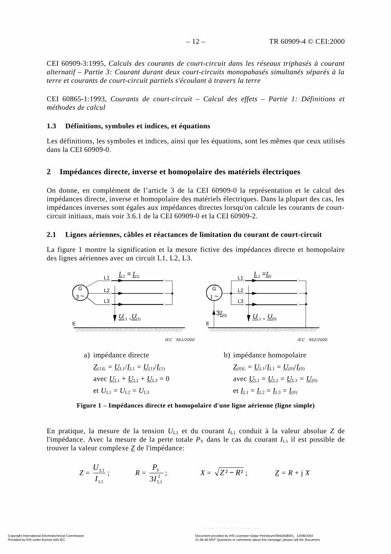
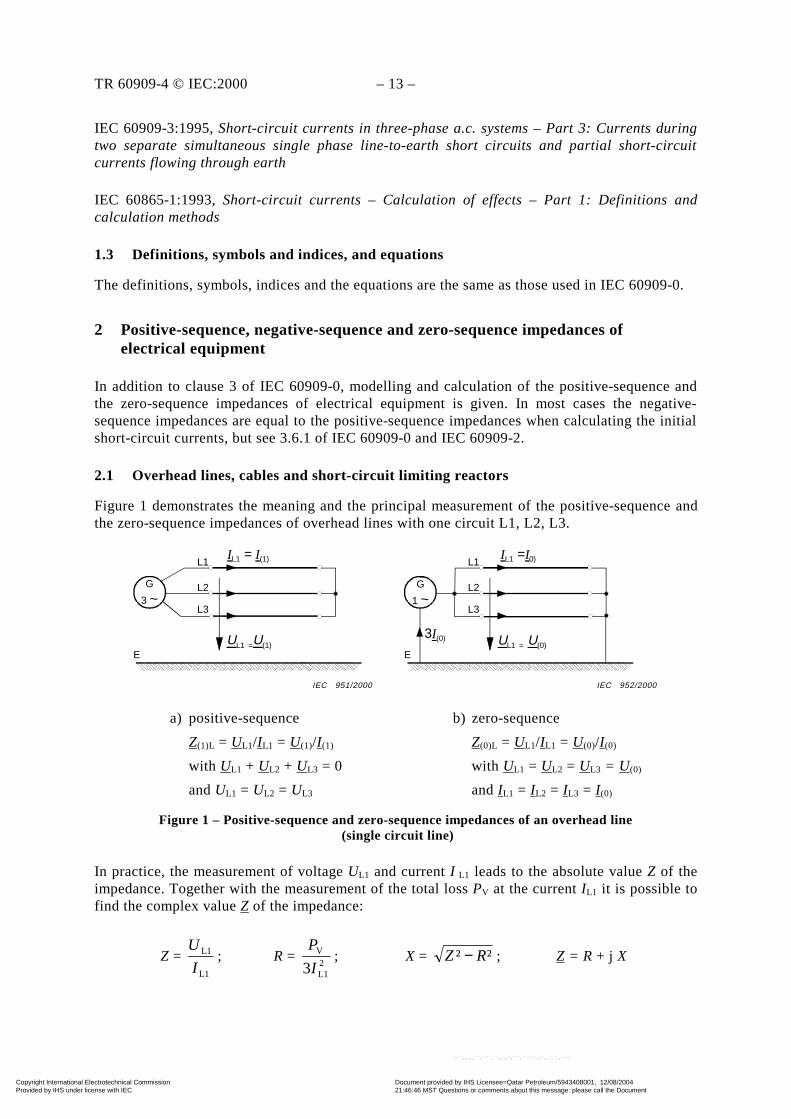
2.1 Lignes aériennes, câbles et réactances de limitation du courant de court-circuit
La figure 1 montre la signification et la mesure fictive des impédances directe et homopolairedes lignes aériennes avec un circuit L1, L2, L3.
a) impédance directe b) impédance homopolaire
Z(1)L = UL1/IL1 = U(1)/I (1) Z(0)L = UL1/IL1 = U(0)/I (0)
avec UL1 + UL2 + UL3 = 0 avec UL1 = UL2 = UL3 = U (0)
et UL1 = UL2 = UL3 et IL1 = IL2 = IL3 = I (0)
Figure 1 – Impédances directe et homopolaire d'une ligne aérienne (ligne simple)
En pratique, la mesure de la tension UL1 et du courant IL1 conduit à la valeur absolue Z del'impédance. Avec la mesure de la perte totale PV dans le cas du courant IL1 il est possible detrouver la valeur complexe Z de l'impédance:
Z = L1
L1
I
U; R =
2L1
V
3I
P; X = ²² RZ − ; Z = R + j X
L1
L2
L3
IL1 = I(1)
UL1 =U(1)
G
3 ~
E
L1
L2
L3
IL1 =I0)
UL1 = U(0)
G
1 ~
E
3I(0)
IEC 952/2000IEC 951/2000
Copyright International Electrotechnical Commission Provided by IHS under license with IEC
Document provided by IHS Licensee=Qatar Petroleum/5943408001, 12/08/200421:46:46 MST Questions or comments about this message: please call the DocumentPolicy Group at 303-397-2295.
--``,,,,,``,````,``,,,,`,```,``-`-`,,`,,`,`,,`---
TR 60909-4 © IEC:2000 – 13 –
IEC 60909-3:1995, Short-circuit currents in three-phase a.c. systems – Part 3: Currents duringtwo separate simultaneous single phase line-to-earth short circuits and partial short-circuitcurrents flowing through earth
IEC 60865-1:1993, Short-circuit currents – Calculation of effects – Part 1: Definitions andcalculation methods
1.3 Definitions, symbols and indices, and equations
The definitions, symbols, indices and the equations are the same as those used in IEC 60909-0.
2 Positive-sequence, negative-sequence and zero-sequence impedances ofelectrical equipment
In addition to clause 3 of IEC 60909-0, modelling and calculation of the positive-sequence andthe zero-sequence impedances of electrical equipment is given. In most cases the negative-sequence impedances are equal to the positive-sequence impedances when calculating the initialshort-circuit currents, but see 3.6.1 of IEC 60909-0 and IEC 60909-2.
2.1 Overhead lines, cables and short-circuit limiting reactors
Figure 1 demonstrates the meaning and the principal measurement of the positive-sequence andthe zero-sequence impedances of overhead lines with one circuit L1, L2, L3.
a) positive-sequence b) zero-sequence
Z(1)L = UL1/IL1 = U(1)/I (1) Z(0)L = UL1/IL1 = U(0)/I (0)
with UL1 + UL2 + UL3 = 0 with UL1 = UL2 = UL3 = U (0)
and UL1 = UL2 = UL3 and IL1 = IL2 = IL3 = I (0)
Figure 1 – Positive-sequence and zero-sequence impedances of an overhead line (single circuit line)
In practice, the measurement of voltage UL1 and current I L1 leads to the absolute value Z of theimpedance. Together with the measurement of the total loss PV at the current IL1 it is possible tofind the complex value Z of the impedance:
Z = L1
L1
I
U; R =
2L1
V
3I
P; X = ²² RZ − ; Z = R + j X
L1
L2
L3
IL1 = I(1)
UL1 =U(1)
G
3 ~
E
L1
L2
L3
IL1 =I0)
UL1 = U(0)
G
1 ~
E
3I(0)
IEC 952/2000IEC 951/2000
Copyright International Electrotechnical Commission Provided by IHS under license with IEC
Document provided by IHS Licensee=Qatar Petroleum/5943408001, 12/08/200421:46:46 MST Questions or comments about this message: please call the DocumentPolicy Group at 303-397-2295.
--``,,,,,``,````,``,,,,`,```,``-`-`,,`,,`,`,,`---
– 14 – TR 60909-4 © CEI:2000
Les équations pour le calcul des impédances directe et homopolaire des lignes aériennes avec unou deux circuits parallèles (ligne double) et avec ou sans un ou deux câbles de garde sontdonnées dans la CEI 60909-2. L'impédance inverse est égale à l'impédance directe. Les mesurespermettant de trouver les impédances directe et homopolaire des câbles possédant une gaine, unblindage et une armure sont similaires à celles données à la figure 1. Des exemples sont donnésdans la CEI 60909-2. Dans le cas d'une impédance homopolaire, la mise à la terre de la gaine,respectivement du blindage ou de l'armure, est importante tout comme le nombre de câblesparallèles. Dans le cas de câbles basse tension à quatre conducteurs, la section du conducteur demise à la terre a une influence sur l'impédance homopolaire.
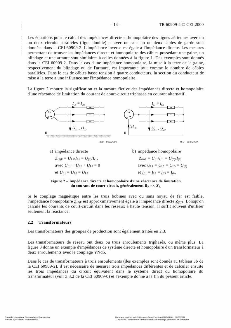
La figure 2 montre la signification et la mesure fictive des impédances directe et homopolaired'une réactance de limitation du courant de court-circuit triphasée en courant alternatif.
a) impédance directe b) impédance homopolaire
Z(1)R = UL1/IL1 = U(1)/I (1) Z(0)R = UL1/IL1 = U(0)/I (0)
avec UL1 + UL2 + UL3 = 0 avec UL1 = UL2 = UL3 = U(0)
et UL1 = UL2 = UL3 et IL1 = IL2 = IL3 = I (0)
Figure 2 – Impédance directe et homopolaire d'une réactance de limitationdu courant de court-circuit, généralement RR << XR
Si le couplage magnétique entre les trois bobines avec ou sans noyau de fer est faible,l'impédance homopolaire Z(0)R est approximativement égale à l'impédance directe Z(1)R. Lorsqu'oncalcule les courants de court-circuit dans les réseaux à haute tension, il suffit souvent d'utiliserseulement la réactance.
2.2 Transformateurs
Les transformateurs des groupes de production sont également traités en 2.3.
Les transformateurs de réseau ont deux ou trois enroulements triphasés, ou même plus. Lafigure 3 donne un exemple d'impédances de système directe et homopolaire d'un transformateur àdeux enroulements avec le couplage YNd5.
Dans le cas de transformateurs à trois enroulements (des exemples sont donnés au tableau 3b dela CEI 60909-2), il est nécessaire de mesurer trois impédances différentes et de calculer ensuiteles trois impédances du circuit équivalent dans le système direct ou homopolaire dutransformateur (voir 3.3.2 de la CEI 60909-0) et l'exemple donné à la fin du présent article.
IL1 = I(1)
UL1 = U(1)
G
3 ~
E
IL1 = I(0)
UL1 = U(1)
G
1 ~
E
3I(0)
~
~
~
~
~
~
IEC 954/2000IEC 953/2000
Copyright International Electrotechnical Commission Provided by IHS under license with IEC
Document provided by IHS Licensee=Qatar Petroleum/5943408001, 12/08/200421:46:46 MST Questions or comments about this message: please call the DocumentPolicy Group at 303-397-2295.
--``,,,,,``,````,``,,,,`,```,``-`-`,,`,,`,`,,`---

TR 60909-4 © IEC:2000 – 15 –
Equations for the calculation of the positive-sequence and the zero-sequence system impedancesof overhead lines with one or two parallel circuits (double circuit line) and without or with oneor two earth wires are given in IEC 60909-2. The negative-sequence impedance is equal to thepositive-sequence impedance. The measurements to find the positive-sequence and the zero-sequence impedances of cables with sheath, shielding and armouring are similar to those givenin figure 1. Examples are given in IEC 60909-2. In the case of the zero-sequence impedance, theearthing of the sheath or the shielding or the armouring is important as well as the number ofparallel cables. In the case of low-voltage four-core cables the cross-section of the earthed corehas an influence on the zero-sequence impedance.
Figure 2 demonstrates the meaning and the principal measurement of the positive-sequence andthe zero-sequence impedance of a three-phase a.c. short-circuit limiting reactor.
a) positive-sequence b) zero-sequence
Z(1)R = UL1/IL1 = U(1)/I (1) Z(0)R = UL1/IL1 = U(0)/I (0)
with UL1 + UL2 + UL3 = 0 with UL1 = UL2 = UL3 = U(0)
and UL1 = UL2 = UL3 and IL1 = IL2 = IL3 = I (0)
Figure 2 – Positive-sequence and zero-sequence impedanceof a short-circuit limiting reactor, generally RR << XR
If the magnetic coupling between the three coils without or with iron core is small, the zero-sequence impedance Z(0)R is approximately equal to the positive-sequence impedance Z(1)R. Whencalculating short-circuit currents in high-voltage systems, it is often sufficient to use thereactance only.
2.2 Transformers
Unit transformers of power-station units are also dealt with in 2.3.
Network transformers have two or three or even more three-phase windings. Figure 3 gives anexample for the positive-sequence and the zero-sequence system impedances of a two-windingtransformer with the vector group YNd5.
In the case of three-winding transformers (examples are given in table 3b of IEC 60909-2), it isnecessary to measure three different impedances and then to calculate the three impedances ofthe equivalent circuit in the positive-sequence or the zero-sequence system of the transformer,see 3.3.2 of IEC 60909-0 and the example at the end of this clause.
IL1 = I(1)
UL1 = U(1)
G
3 ~
E
IL1 = I(0)
UL1 = U(1)
G
1 ~
E
3I(0)
~
~
~
~
~
~
IEC 954/2000IEC 953/2000
Copyright International Electrotechnical Commission Provided by IHS under license with IEC
Document provided by IHS Licensee=Qatar Petroleum/5943408001, 12/08/200421:46:46 MST Questions or comments about this message: please call the DocumentPolicy Group at 303-397-2295.
--``,,,,,``,````,``,,,,`,```,``-`-`,,`,,`,`,,`---
– 16 – TR 60909-4 © CEI:2000
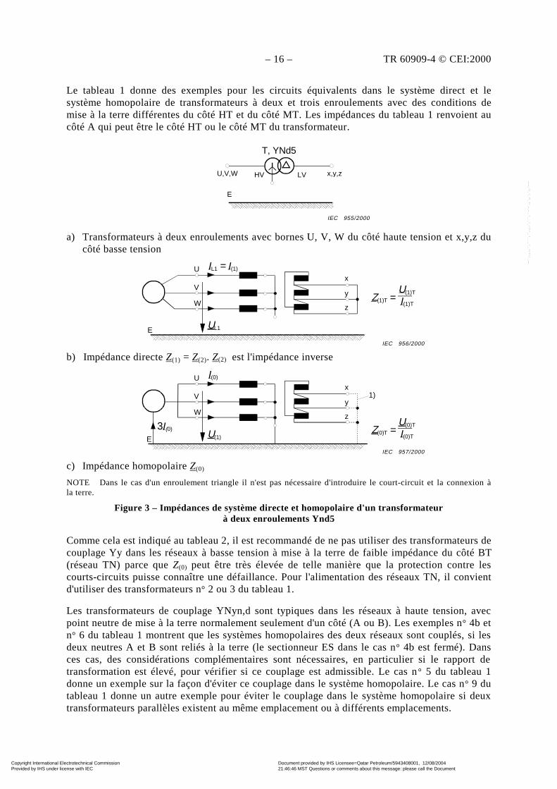
Le tableau 1 donne des exemples pour les circuits équivalents dans le système direct et lesystème homopolaire de transformateurs à deux et trois enroulements avec des conditions demise à la terre différentes du côté HT et du côté MT. Les impédances du tableau 1 renvoient aucôté A qui peut être le côté HT ou le côté MT du transformateur.
a) Transformateurs à deux enroulements avec bornes U, V, W du côté haute tension et x,y,z ducôté basse tension
IL1 = I(1)
UL1
G
3 ~
E
U
V
W
x
y
zI(1)T
Z(1)T =U(1)T
b) Impédance directe Z(1) = Z(2). Z(2) est l'impédance inverse
I(0)
U(1)
G
3 ~
E
U
V
W
x
y
z
I(0)TZ(0)T =
U(0)T3I(0)
1)
c) Impédance homopolaire Z(0)
NOTE Dans le cas d'un enroulement triangle il n'est pas nécessaire d'introduire le court-circuit et la connexion àla terre.
Figure 3 – Impédances de système directe et homopolaire d'un transformateurà deux enroulements Ynd5
Comme cela est indiqué au tableau 2, il est recommandé de ne pas utiliser des transformateurs decouplage Yy dans les réseaux à basse tension à mise à la terre de faible impédance du côté BT(réseau TN) parce que Z(0) peut être très élevée de telle manière que la protection contre lescourts-circuits puisse connaître une défaillance. Pour l'alimentation des réseaux TN, il convientd'utiliser des transformateurs n° 2 ou 3 du tableau 1.
Les transformateurs de couplage YNyn,d sont typiques dans les réseaux à haute tension, avecpoint neutre de mise à la terre normalement seulement d'un côté (A ou B). Les exemples n° 4b etn° 6 du tableau 1 montrent que les systèmes homopolaires des deux réseaux sont couplés, si lesdeux neutres A et B sont reliés à la terre (le sectionneur ES dans le cas n° 4b est fermé). Dansces cas, des considérations complémentaires sont nécessaires, en particulier si le rapport detransformation est élevé, pour vérifier si ce couplage est admissible. Le cas n° 5 du tableau 1donne un exemple sur la façon d'éviter ce couplage dans le système homopolaire. Le cas n° 9 dutableau 1 donne un autre exemple pour éviter le couplage dans le système homopolaire si deuxtransformateurs parallèles existent au même emplacement ou à différents emplacements.
HV LVU,V,W x,y,z
T, YNd5
E
IEC 955/2000
IEC 956/2000
IEC 957/2000
Copyright International Electrotechnical Commission Provided by IHS under license with IEC
Document provided by IHS Licensee=Qatar Petroleum/5943408001, 12/08/200421:46:46 MST Questions or comments about this message: please call the DocumentPolicy Group at 303-397-2295.
--``,,,,,``,````,``,,,,`,```,``-`-`,,`,,`,`,,`---
TR 60909-4 © IEC:2000 – 17 –
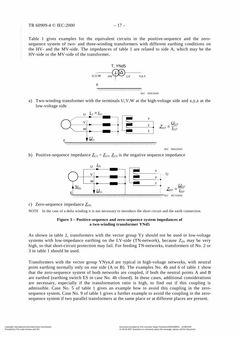
Table 1 gives examples for the equivalent circuits in the positive-sequence and the zero-sequence system of two- and three-winding transformers with different earthing conditions onthe HV- and the MV-side. The impedances of table 1 are related to side A, which may be theHV-side or the MV-side of the transformer.
a) Two-winding transformer with the terminals U,V,W at the high-voltage side and x,y,z at thelow-voltage side
IL1 = I(1)
UL1
G
3 ~
E
U
V
W
x
y
zI(1)T
Z(1)T =U(1)T
b) Positive-sequence impedance Z(1) = Z(2). Z(2) is the negative sequence impedance
I(0)
U(1)
G
3 ~
E
U
V
W
x
y
z
I(0)TZ(0)T =
U(0)T3I(0)
1)
c) Zero-sequence impedance Z(0)
NOTE In the case of a delta winding it is not necessary to introduce the short circuit and the earth connection.
Figure 3 – Positive-sequence and zero-sequence system impedances ofa two-winding transformer YNd5
As shown in table 2, transformers with the vector group Yy should not be used in low-voltagesystems with low-impedance earthing on the LV-side (TN-network), because Z(0) may be veryhigh, so that short-circuit protection may fail. For feeding TN-networks, transformers of No. 2 or3 in table 1 should be used.
Transformers with the vector group YNyn,d are typical in high-voltage networks, with neutralpoint earthing normally only on one side (A or B). The examples No. 4b and 6 of table 1 showthat the zero-sequence system of both networks are coupled, if both the neutral points A and Bare earthed (earthing switch ES in case No. 4b closed). In these cases, additional considerationsare necessary, especially if the transformation ratio is high, to find out if this coupling isadmissible. Case No. 5 of table 1 gives an example how to avoid this coupling in the zero-sequence system. Case No. 9 of table 1 gives a further example to avoid the coupling in the zero-sequence system if two parallel transformers at the same place or at different places are present.
HV LVU,V,W x,y,z
T, YNd5
E
IEC 955/2000
IEC 956/2000
IEC 957/2000
Copyright International Electrotechnical Commission Provided by IHS under license with IEC
Document provided by IHS Licensee=Qatar Petroleum/5943408001, 12/08/200421:46:46 MST Questions or comments about this message: please call the DocumentPolicy Group at 303-397-2295.
--``,,,,,``,````,``,,,,`,```,``-`-`,,`,,`,`,,`---
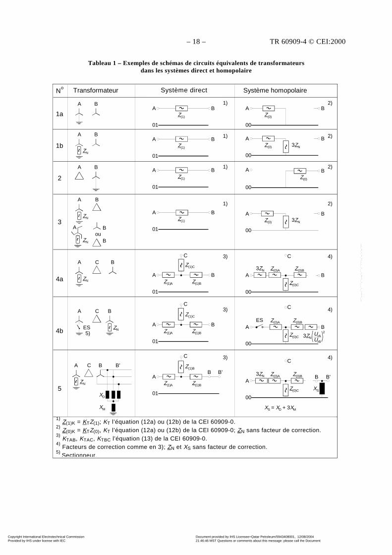
– 18 – TR 60909-4 © CEI:2000
Tableau 1 – Exemples de schémas de circuits équivalents de transformateursdans les systèmes direct et homopolaire
A B
01
Z(1)
A B
01
Z(1)
A B
01
Z(1)
A B
A B
ZN
A B
A
ZN
B
ZN
Aou
B
B
A
ZN
C B
A
ES5)
C
ZN
B
ZN
A C B B'
XD
XM
A B
01
Z(1)
A B
01
Z(1)A Z(1)B
Z(1)C
C
A B
01
Z(1)A Z(1)B
Z(1)C
C
AB
01
Z(1)A Z(1)B
Z(1)B
C
B'
A
00
Z(0)
B
A
00
Z(0)
B3ZN
00
Z(0)
BA
A
00
Z(0)
B3ZN
A
00
3ZN
BZ(0)A Z(0)B
Z(0)C
C
A
00
ESB
Z(0)A Z(0)B
Z(0)C
C
3ZNUrAUrB
2
A
00
3ZN BZ(0)A Z(0)B
Z(0)C
C
XS
B'
XS = XD + 3XM
No. Transformateur Système direct neutre Système homopolaire
1a
1b
2
3
4a
4b
5
3) 4)
3) 4)
3) 4)
1) 2)
1) 2)
1) 2)
1) 2)
1) Z(1)K = KTZ(1); KT L’équation (12a) ou (12b) de la CEI 60909-0.2) Z(0)K = KTZ(0), KT l’équation (12a) ou (12b) de la CEI 609090-0; ZN sans facteur de correction3) KTAB , KTAC, KTBC l’équation (13) de la CEI 60909-0.4) Facteurs de correction comme en 3); Z N et X S sans facteur de correction5) Sectionneur
1) Z(1)K = KTZ(1); KT l’équation (12a) ou (12b) de la CEI 60909-0.
2) Z(0)K = KTZ(0), KT l’équation (12a) ou (12b) de la CEI 60909-0; ZN sans facteur de correction.
3) KTAB, KTAC, KTBC l’équation (13) de la CEI 60909-0.
4) Facteurs de correction comme en 3); ZN et XS sans facteur de correction.
5) Sectionneur.
No Système direct
Copyright International Electrotechnical Commission Provided by IHS under license with IEC
Document provided by IHS Licensee=Qatar Petroleum/5943408001, 12/08/200421:46:46 MST Questions or comments about this message: please call the DocumentPolicy Group at 303-397-2295.
--``,,,,,``,````,``,,,,`,```,``-`-`,,`,,`,`,,`---

TR 60909-4 © IEC:2000 – 19 –
Table 1 – Examples for equivalent circuit-diagrams of transformers in the positive-sequenceand the zero-sequence system
A B
01
Z(1)
A B
01
Z(1)
A B
01
Z(1)
A B
A B
ZN
A B
A
ZN
B
ZN
Aor
B
B
A
ZN
C B
A
ES5)
C
ZN
B
ZN
A C B B'
XD
XM
A B
01
Z(1)
A B
01
Z(1)A Z(1)B
Z(1)C
C
A B
01
Z(1)A Z(1)B
Z(1)C
C
AB
01
Z(1)A Z(1)B
Z(1)B
C
B'
A
00
Z(0)
B
A
00
Z(0)
B3ZN
00
Z(0)
BA
A
00
Z(0)
B3ZN
A
00
3ZN
BZ(0)A Z(0)B
Z(0)C
C
A
00
ESB
Z(0)A Z(0)B
Z(0)C
C
3ZNUrAUrB
2
A
00
3ZN BZ(0)A Z(0)B
Z(0)C
C
XS
B'
XS = XD + 3XM
No. Transformer Positive-sequence system Zero-sequence system
1a
1b
2
3
4a
4b
5
3) 4)
3) 4)
3) 4)
1) 2)
1) 2)
1) 2)
1) 2)
1) Z(1)K = KTZ(1); KT from equation (12a) or (12b) of IEC 60909-02) Z(0)K = KTZ(0), KT from equation (12a) or (12b) of IEC 60909-0; ZN without correction factor3) KTAB, KTAC, KTBC from equation (13) of IEC 60909-04) Correction factors as indicated under 3); ZN and XS without correction factor5) Earthing switch
1) Z(1)K = KTZ(1); KT from equation (12a) or (12b) of IEC 60909-0.
2) Z(0)K = KTZ(0), KT from equation (12a) or (12b) of IEC 60909-0; ZN without correction factor.
3) KTAB, KTAC, KTBC from equation (13) of IEC 60909-0.
4) Correction factors as indicated under 3); ZN and XS without correction factor.
5) Earthing switch.
No.
Copyright International Electrotechnical Commission Provided by IHS under license with IEC
Document provided by IHS Licensee=Qatar Petroleum/5943408001, 12/08/200421:46:46 MST Questions or comments about this message: please call the DocumentPolicy Group at 303-397-2295.
--``,,,,,``,````,``,,,,`,```,``-`-`,,`,,`,`,,`---
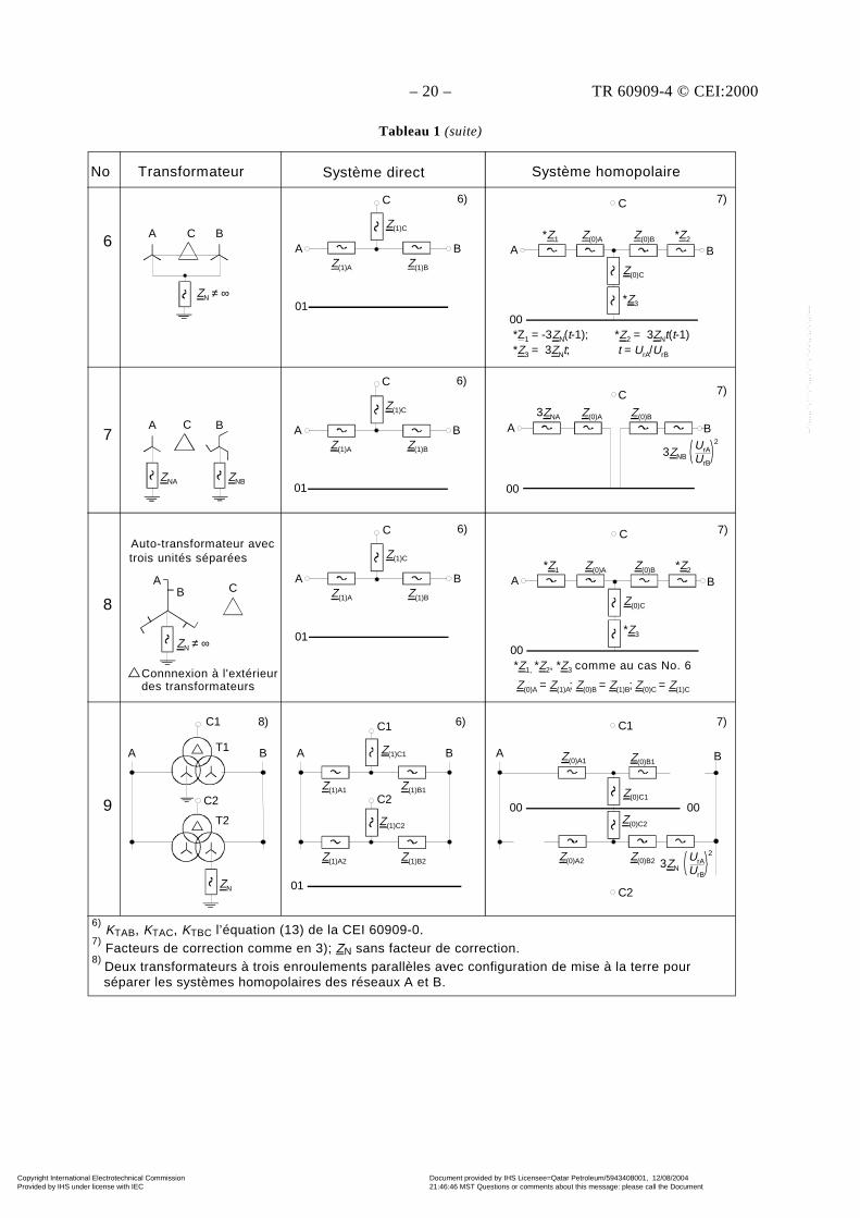
– 20 – TR 60909-4 © CEI:2000
Tableau 1 (suite)
A
01
Z(1)A
A CA
00
*Z1
B6
6)
No. Transformer Positive-sequence system Zero-sequence system
B
ZN ≠ ∞
B
C
Z(1)C
Z(1)B
C 7)
Z(0)A Z(0)B *Z2
Z(0)C
*Z3
*Z1 = -3ZN(t-1); *Z2 = 3ZNt(t-1)*Z3 = 3ZNt; t = UrA/UrB
A
01
Z(1)A
A C A
00
B
6)
B B
C
Z(1)C
Z(1)B
C 7)
Z(0)A Z(0)B
ZNA ZNB
3ZNA
3ZNBUrA
UrB
2
A
00
*Z1
B
C 7)
Z(0)A Z(0)B *Z2
Z(0)C
*Z3
*Z1, *Z2, *Z3 as in case No. 6
Z(0)A = Z(1)A; Z(0)B = Z(1)B; Z(0)C = Z(1)C
A
00
B
C1 7)
Z(0)A1 Z(0)B1
Z(0)C1
Z(0)C2
Z(0)B2 3ZNUrAUrB
2Z(0)A2
00
C2
A
01
Z(1)A
AB
6)
B
C
Z(1)C
Z(1)B
ZN ≠ ∞
C
- connnection outside the transformers
Auto-transformer withthree separate units
C1
ZN
A
C2
A
C2
BT1
T2
B
C1
Z(1)C1
Z(1)A1 Z(1)B1
Z(1)A2 Z(1)B2
Z(1)C2
01
6)
7
8
9
6) KTAB, KRAC, KTBC from equation (13) of IEC 60909-07) Correction factors as indicated under 3); ZN without correction factor8) Two parallel three-winding transformers with an earthing pattern to separate the zero-sequence systems of the networks A and B
8)
6) KTAB, KTAC, KTBC l’équation (13) de la CEI 60909-0.
7) Facteurs de correction comme en 3); ZN sans facteur de correction.
8) Deux transformateurs à trois enroulements parallèles avec configuration de mise à la terre pour
séparer les systèmes homopolaires des réseaux A et B.
No Transformateur Système direct Système homopolaireNo Transformateur Système direct Système homopolaire
Connnexion à l'extérieurdes transformateurs
Auto-transformateur avectrois unités séparées
comme au cas No. 6
Copyright International Electrotechnical Commission Provided by IHS under license with IEC
Document provided by IHS Licensee=Qatar Petroleum/5943408001, 12/08/200421:46:46 MST Questions or comments about this message: please call the DocumentPolicy Group at 303-397-2295.
--``,,,,,``,````,``,,,,`,```,``-`-`,,`,,`,`,,`---
TR 60909-4 © IEC:2000 – 21 –
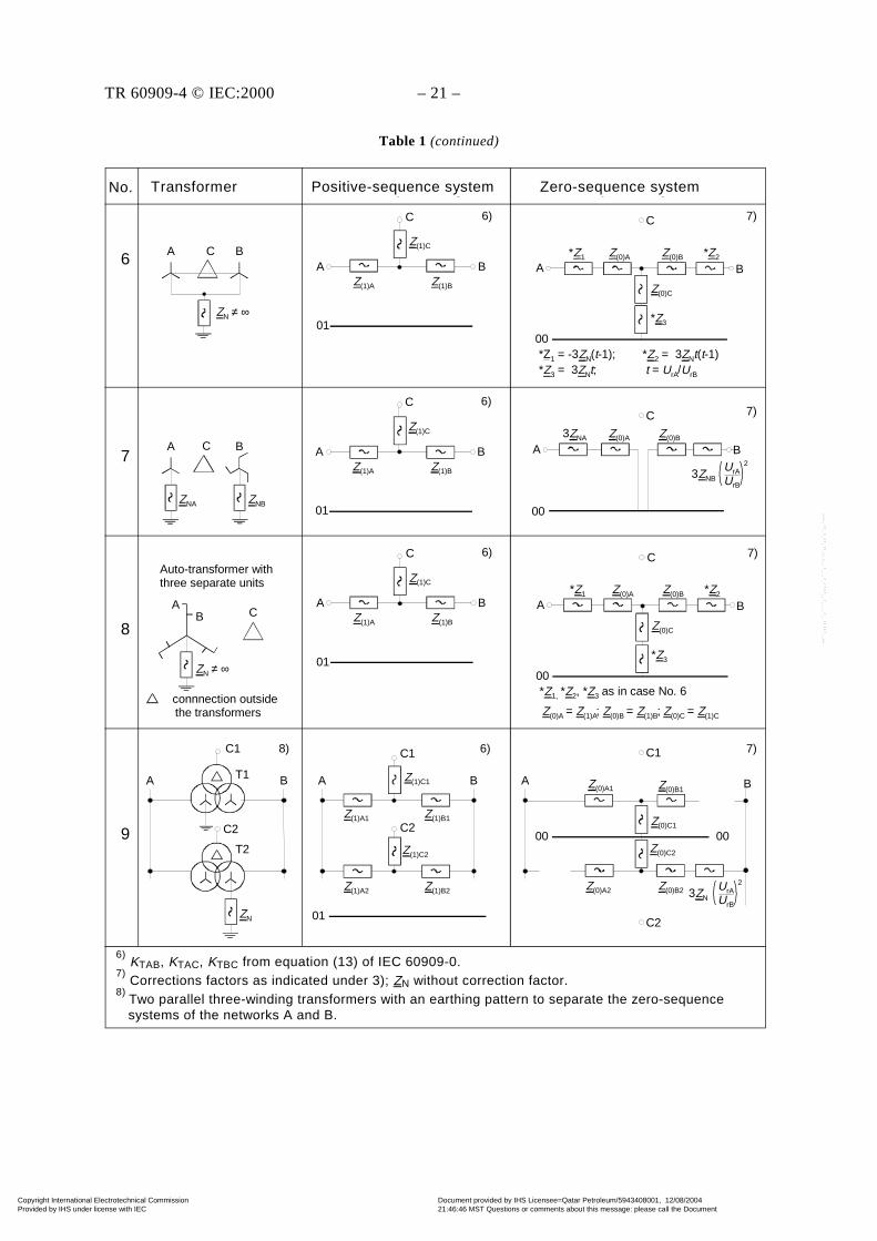
Table 1 (continued)
A
01
Z(1)A
A CA
00
*Z1
B6
6)
No. Transformer Positive-sequence system Zero-sequence system
B
ZN ≠ ∞
B
C
Z(1)C
Z(1)B
C 7)
Z(0)A Z(0)B *Z2
Z(0)C
*Z3
*Z1 = -3ZN(t-1); *Z2 = 3ZNt(t-1)*Z3 = 3ZNt; t = UrA/UrB
A
01
Z(1)A
A C A
00
B
6)
B B
C
Z(1)C
Z(1)B
C 7)
Z(0)A Z(0)B
ZNA ZNB
3ZNA
3ZNBUrA
UrB
2
A
00
*Z1
B
C 7)
Z(0)A Z(0)B *Z2
Z(0)C
*Z3
*Z1, *Z2, *Z3 as in case No. 6
Z(0)A = Z(1)A; Z(0)B = Z(1)B; Z(0)C = Z(1)C
A
00
B
C1 7)
Z(0)A1 Z(0)B1
Z(0)C1
Z(0)C2
Z(0)B2 3ZNUrAUrB
2Z(0)A2
00
C2
A
01
Z(1)A
AB
6)
B
C
Z(1)C
Z(1)B
ZN ≠ ∞
C
- connnection outside the transformers
Auto-transformer withthree separate units
C1
ZN
A
C2
A
C2
BT1
T2
B
C1
Z(1)C1
Z(1)A1 Z(1)B1
Z(1)A2 Z(1)B2
Z(1)C2
01
6)
7
8
9
6) KTAB, KRAC, KTBC from equation (13) of IEC 60909-07) Correction factors as indicated under 3); ZN without correction factor8) Two parallel three-winding transformers with an earthing pattern to separate the zero-sequence systems of the networks A and B
8)
6) KTAB, KTAC, KTBC from equation (13) of IEC 60909-0.
7) Corrections factors as indicated under 3); ZN without correction factor.
8) Two parallel three-winding transformers with an earthing pattern to separate the zero-sequence
systems of the networks A and B.
No Transformer Positive-sequence system Zero-sequence systemNo.
Copyright International Electrotechnical Commission Provided by IHS under license with IEC
Document provided by IHS Licensee=Qatar Petroleum/5943408001, 12/08/200421:46:46 MST Questions or comments about this message: please call the DocumentPolicy Group at 303-397-2295.
--``,,,,,``,````,``,,,,`,```,``-`-`,,`,,`,`,,`---
– 22 – TR 60909-4 © CEI:2000
Dans le cas n° 8 pour les auto-transformateurs avec point neutre de mise à la terre ZN ≠ ∞, troisunités séparées, et un enroulement auxiliaire complémentaire en connexion triangle, le couplageentre les systèmes homopolaires des réseaux connectés aux deux côtés du transformateur ne peutpas être évité. Pour trouver les impédances *Z1, *Z2 et *Z3 en fonction de ZN ≠ ∞, des calculsspécifiques sont nécessaires comme indiqué au cas n° 6 du tableau 1.
Les transformateurs survolteurs dévolteurs (ou transformateurs de régulation pour la commandede la tension et/ou de l'angle de déphasage) sont représentés comme des transformateurs réseauavec un équivalent généralement de la forme n° 6 du tableau 1. Les dispositions de constructionet de connexion des transformateurs shunt déterminent si Z(0)C a une valeur faible finie et, dansce cas, il est nécessaire de mesurer trois impédances différentes, comme avec les transformateursà trois enroulements, pour calculer les impédances du circuit équivalent.
Le tableau 2 donne quelques approximations pour les rapports X(0)T/XT des transformateurs si unpoint neutre du transformateur est relié à la terre. Dans le cas de transformateurs à trois enroule-ments (cas n° 4 à 7 et 9 du tableau 1), la réactance XT = X(1)T est donnée par X(1)T = X(1)A + X(1)B.
Tableau 2 – Approximations des rapports X(0)T/XT des transformateurs à deux et trois enroulements
CouplageConstruction destransformateurs
YNd ou Dyn Yzn YNyn,d YNy 3) ou Ynz
Trois noyaux
Cinq noyaux
Trois transformateurs ànoyau unique
0,7...1,0 1)
1,0
1,0
0,1...0,15 1...3,5 2)
3...10
10...100
10...100
1) Transformateurs à faible puissance apparente: X(0)T/XT ≈ 1,0 (par exemple transformateurs basse tension Dyn5avec SrT = 400 kVA, UrTHV/UrTLV = 10 kV/0,4 kV).
2) Le rapport X(0)T/XT dépend de la construction du transformateur (voir la CEI 60909-2).3) Il est recommandé de ne pas utiliser les transformateurs Yy dans les réseaux à mise à la terre de faible
impédance, par exemple dans les réseaux TN basse tension (voir la CEI 61200-413).
Exemple pour les impédances et les circuits équivalents d'un transformateur réseau à troisenroulements YNyn,d5, SrTHVMV = 350 MVA
La figure 4 donne les circuits équivalents d'un transformateur réseau à trois enroulements dansles systèmes direct et homopolaire. Le système inverse est égal au système direct (voir n° 4 dansle tableau 1).
a) Couplage et bornes du b) Système direct c) Système homopolairetransformateur YNyn,d5
Figure 4 – Circuits équivalents d'un transformateur réseau à trois enroulements
C
~
LV
A B
MVHV
N n
~
~
BA
C
ZC
ZBZA
01
~ ~
~
BA
Z(0)C
Z(0)BZ(0)A
01
C
IEC 958/2000 IEC 959/2000 IEC 960/2000
Copyright International Electrotechnical Commission Provided by IHS under license with IEC
Document provided by IHS Licensee=Qatar Petroleum/5943408001, 12/08/200421:46:46 MST Questions or comments about this message: please call the DocumentPolicy Group at 303-397-2295.
--``,,,,,``,````,``,,,,`,```,``-`-`,,`,,`,`,,`---
TR 60909-4 © IEC:2000 – 23 –
In case No. 8 for auto-transformers with neutral point earthing ZN ≠ ∞, three separate units andan additional auxiliary winding in delta connection, the coupling between the zero-sequencesystems of the networks connected to both sides of the transformer cannot be avoided. To findthe impedances *Z1, *Z2 and *Z3 as a function of ZN ≠ ∞, special calculations are necessary asgiven under case No. 6 in table 1.
Booster transformers (or regulating transformers for voltage and/or phase-angle control) arerepresented as network transformers with an equivalent generally of form No. 6 in table 1. Theconstruction and connection arrangement of shunt transformers will determine whether Z(0)C hasa finite low value and, in this case, it will be necessary to measure three different impedances, aswith three-winding transformers, in order to calculate the impedances of the equivalent circuit.
Table 2 gives some approximations for the ratios X(0)T/XT of transformers, if one neutral point ofthe transformer is earthed. In the case of three-winding transformers (cases No. 4 to 7 and 9 oftable 1), the reactance XT = X(1)T is given by X(1)T = X(1)A + X(1)B.
Table 2 – Approximations for the ratios X(0)T/XT of two- and three-winding transformers
Vector groupConstruction oftransformers
YNd or Dyn Yzn YNyn,d YNy 3) or YNz
Three cores 0,7...1,0 1) 3...10
Five cores 1,0 0,1...0,15 1...3,5 2) 10...100
Three single-coretransformers
1,0 10...100
1) Transformers with small apparent power: X(0)T/XT ≈ 1,0 (for instance low-voltage transformers Dyn5 with SrT = 400 kVA,UrTHV/UrTLV = 10 kV/0,4 kV).
2) The ratio X(0)T/XT depends on the construction of the transformer, see IEC 60909-2.3) Transformers Yy should not be used in networks with low impedance earthing, for instance in low-voltage TN-networks (see
IEC 61200-413).
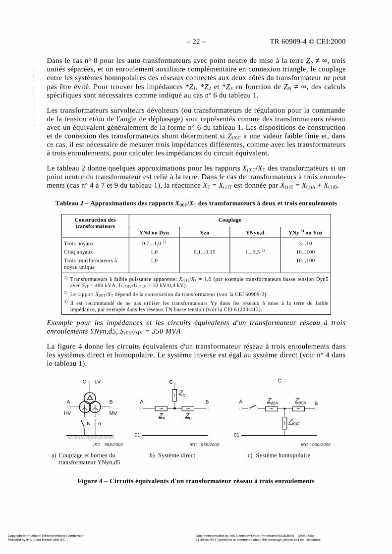
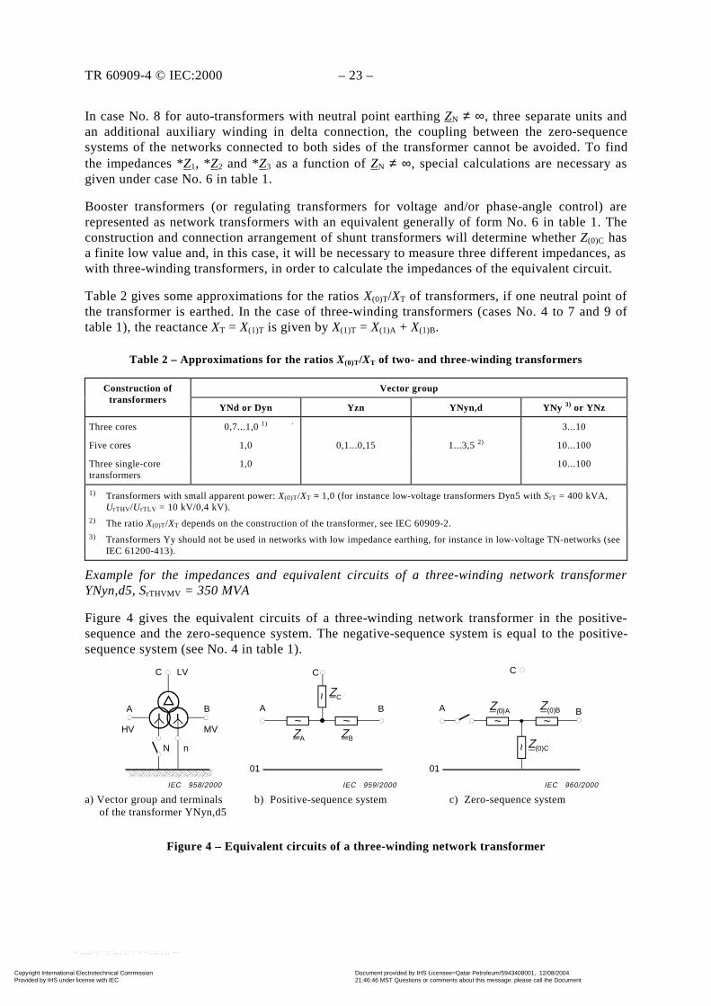
Example for the impedances and equivalent circuits of a three-winding network transformerYNyn,d5, SrTHVMV = 350 MVA
Figure 4 gives the equivalent circuits of a three-winding network transformer in the positive-sequence and the zero-sequence system. The negative-sequence system is equal to the positive-sequence system (see No. 4 in table 1).
a) Vector group and terminals b) Positive-sequence system c) Zero-sequence system of the transformer YNyn,d5
Figure 4 – Equivalent circuits of a three-winding network transformer
C
~
LV
A B
MVHV
N n
~
~
BA
C
ZC
ZBZA
01
~ ~
~
BA
Z(0)C
Z(0)BZ(0)A
01
C
IEC 958/2000 IEC 959/2000 IEC 960/2000
Copyright International Electrotechnical Commission Provided by IHS under license with IEC
Document provided by IHS Licensee=Qatar Petroleum/5943408001, 12/08/200421:46:46 MST Questions or comments about this message: please call the DocumentPolicy Group at 303-397-2295.
--``,,,,,``,````,``,,,,`,```,``-`-`,,`,,`,`,,`---
– 24 – TR 60909-4 © CEI:2000
rTHVLV
2rTMVXrHVLVRrHVLV
%100j
%100 S
Uuu
+
rTMVLV
2rTMVXrMVLVRrMVLV
%100j
%100 S
Uuu
+
Les caractéristiques suivantes sont données ou trouvées grâce aux mesures:
UrTHV = 400 kV; UrTMV = 120 kV; UrTLV = 30 kV
SrTHV = 350 MVA; SrTMV = 350 MVA; SrTLV = 50 MVA
ukrHVMV = 21 %; uRrHVMV = 0,26 %; se référant à SrTHVMV = 350 MVA, UrTHV = 400 kV;
ukrHVLV = 10 %; uRrHVLV = 0,16 %; se référant à SrTHVLV = 50 MVA, UrTHV = 400 kV;
ukrMVLV = 7 %; uRrMVLV = 16 %; se référant à SrTHVLV = 50 MVA, UrTMV = 120 kV;
A partir des équations (10) de la CEI 60909-0 on trouve les impédances suivantes des systèmesdirects, côté B – MT:
ZAB = rTHVMV
2rTMVXrHVMVRrHVMV
%100j
%100 S
Uuu
+ = (0,106971 + j 8,639338) Ω
ZAC = = (0,460800 + j 28,796313) Ω
ZBC = = (0,460800 + j 20,154733) Ω
Les calculs sont effectués à six chiffres après la virgule, parce que cet exemple est égalementutilisé pour le réseau d'essai mentionné à l'article 6 (transformateurs T3 = T4).
Avec les réactances relatives assignées XT obtenues à partir de la tension de court-circuit
réactive uXr = 2Rr
2kr uu − selon l’équation (10d) de la CEI 60909-0, on obtient les facteurs de
correction d'impédance suivants (voir l’équation (13) de la CEI 60909-0):
KTAB = 0,95 TAB
max
0,61 x
c
+ = 0,95
209984,06,01
1,1×+
= 0,928072
KTAC = 0,95 TAC
max
6,01 x+c
= 0,95 099987,06,01
1,1×+
= 0,985856
KTBC = 0,95 TBC
max
6,01 x
c
+ = 0,95
069982,06,011,1
×+ = 1,002890
Avec ces facteurs de correction, par exemple ZABK = KTABZAB, on obtient les impédancescorrigées suivantes (indice K):
ZABK = (0,099277 + j 8,017927) Ω
ZACK = (0,454283 + j 28,389024) Ω
ZBCK = (0,462132 + j 20,212973) Ω
Les impédances directes corrigées équivalentes à la figure 4b, côté MT sont calculées avecl’équation (11) de la CEI 60909-0.
ZAK = (0,045714 + j 8,096989) Ω
ZBK = (0,053563 – j 0,079062) Ω
ZCK = (0,408568 + j 20,292035) Ω
Copyright International Electrotechnical Commission Provided by IHS under license with IEC
Document provided by IHS Licensee=Qatar Petroleum/5943408001, 12/08/200421:46:46 MST Questions or comments about this message: please call the DocumentPolicy Group at 303-397-2295.
--``,,,,,``,````,``,,,,`,```,``-`-`,,`,,`,`,,`---

TR 60909-4 © IEC:2000 – 25 –
rTHVLV
2rTMVXrHVLVRrHVLV
%100j
%100 S
Uuu
+
rTMVLV
2rTMVXrMVLVRrMVLV
%100j
%100 S
Uuu
+
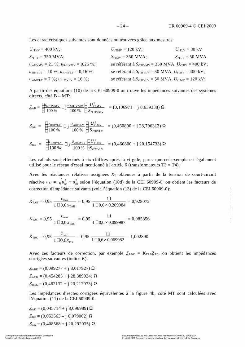
The following data are given or found from measurements:
UrTHV = 400 kV; UrTMV = 120 kV; UrTLV = 30 kV
SrTHV = 350 MVA; SrTMV = 350 MVA; SrTLV = 50 MVA
ukrHVMV = 21 %; uRrHVMV = 0,26 %; referred to SrTHVMV = 350 MVA, UrTHV = 400 kV;
ukrHVLV = 10 %; uRrHVLV = 0,16 %; referred to SrTHVLV = 50 MVA, UrTHV = 400 kV;
ukrMVLV = 7 %; uRrMVLV = 16 %; referred to SrTHVLV = 50 MVA, UrTMV = 120 kV;
From equations (10) in IEC 60909-0 the following impedances of the positive-sequence systemare found, related to the MV-side B:
ZAB = rTHVMV
2rTMVXrHVMVRrHVMV
%100j
%100 S
Uuu
+ = (0,106971 + j 8,639338) Ω
ZAC = = (0,460800 + j 28,796313) Ω
ZBC = = (0,460800 + j 20,154733) Ω
The calculations are carried out here with six-figure numbers following the decimal comma,because this example is used also for the test network in clause 6 (transformers T3 = T4).
With the rated relative reactances XT found from the reactive short-circuit voltage uXr =2Rr
2kr uu − according to equation (10d) of IEC 60909-0, the following impedance correction
factors (equation (13) of IEC 60909-0) are found:
KTAB = 0,95 TAB
max
0,61 x
c
+ = 0,95
209984,06,01
1,1×+
= 0,928072
KTAC = 0,95 TAC
max
6,01 x+c
= 0,95 099987,06,01
1,1×+
= 0,985856
KTBC = 0,95 TBC
max
6,01 x
c
+ = 0,95
069982,06,011,1
×+ = 1,002890
Together with these correction factors, for instance ZABK = KTABZAB, the following correctedimpedances (index K) are found:
ZABK = (0,099277 + j 8,017927) Ω
ZACK = (0,454283 + j 28,389024) Ω
ZBCK = (0,462132 + j 20,212973) Ω
The corrected equivalent positive-sequence impedances in figure 4b, related to the MV-side, arecalculated with equation (11) of IEC 60909-0.
ZAK = (0,045714 + j 8,096989) Ω
ZBK = (0,053563 – j 0,079062) Ω
ZCK = (0,408568 + j 20,292035) Ω
Copyright International Electrotechnical Commission Provided by IHS under license with IEC
Document provided by IHS Licensee=Qatar Petroleum/5943408001, 12/08/200421:46:46 MST Questions or comments about this message: please call the DocumentPolicy Group at 303-397-2295.
--``,,,,,``,````,``,,,,`,```,``-`-`,,`,,`,`,,`---

– 26 – TR 60909-4 © CEI:2000
Pour le modèle équivalent du transformateur dans le système homopolaire (figure 4c) lesréactances suivantes sont connues avec le côté moyenne tension B:
X(0)A = 8,5551 Ω; X(0)B = – 0,6881 Ω; X(0)C = 18,8307 Ω
Si seul le point neutre moyenne tension du transformateur est mis à la terre, la réactancehomopolaire effective est la somme de X(0)B et X(0)C conduisant à X(0)MVK lorsqu'on introduit lefacteur de correction d'impédance KTBC:
X(0)MVK = KTBC(X(0)B + X(0)C) = 18,195032 Ω
Ceci conduit au rapport X(0)T/XT = (X(0)B + X(0)C)/XAB = 18,1426 Ω/8,639 338 Ω = 2,0999 ≈ 2,1sans facteur de correction.
Dans beaucoup de cas, les transformateurs réseau à trois enroulements avec un enroulementtriangle auxiliaire (par exemple YNyn,d5) peuvent être traités comme des transformateurs à deuxenroulements (voir, par exemple, les transformateurs T4, T5 et T6 à la figure 16).
Pour cet exemple (transformateur T4 à la figure 16) le calcul devient bien plus facile, enparticulier si les résistances sont négligées (RT/XT ≈ 0,012):
XT = XAB = 8,639 338 Ω; KT = KTAB = 0,928 072; XTK = KTXT = 8,017 927 Ω; X(0)T = 2,1 × XT =18,1426 Ω et avec KT = KTAB: X(0)TK = 16,838 Ω du côté sans variation en comparaison de X(0)TK
= KTBCX(0)T = 18,195 Ω ce qui a été obtenu avec le calcul complexe ci-dessus.
2.3 Alternateurs et groupes de production
2.3.1 Pour les alternateurs synchrones sans transformateur dans les réseaux basse et moyenne
tensions, les réactances directes sont ″dX , '
dX ET Xd (voir la CEI 60909-2). Au début du court-
circuit, la réactance subtransitoire "dX donne "kI .
La réactance du système inverse est approximativement égale à la réactance subtransitoire: X(2) ≈"dX . Si "
qX est très différent de "dX alors il convient d'utiliser X(2) = 0,5 ( "
dX + "qX ) (voir la
CEI 60909-0).
La réactance homopolaire X(0) est inférieure à la réactance subtransitoire, en fonction de laconfiguration d'enroulement de la machine synchrone (voir la CEI 60909-2). Si le point neutrede l’alternateur doit être mis à la terre par une impédance complémentaire de préférenceune réactance, entre point neutre et terre pour limiter le courant de court-circuit phase-terre
("1kI ≤ "
kI ) et/ou pour supprimer les courants de 3e ordre dans le cas d'alternateurs en parallèle,ou en parallèle avec des transformateurs ayant une mise à la terre de neutre dans la même partiedu réseau, alors le facteur de correction d'impédance KG doit être utilisé dans le système direct,inverse et homopolaire mais KG ne doit pas être utilisé pour l'impédance de neutre complé-mentaire (voir 3.6.1 de la CEI 60909-0).
Copyright International Electrotechnical Commission Provided by IHS under license with IEC
Document provided by IHS Licensee=Qatar Petroleum/5943408001, 12/08/200421:46:46 MST Questions or comments about this message: please call the DocumentPolicy Group at 303-397-2295.
--``,,,,,``,````,``,,,,`,```,``-`-`,,`,,`,`,,`---

TR 60909-4 © IEC:2000 – 27 –
For the equivalent model of the transformer in the zero-sequence system (figure 4c) thefollowing reactances are known, related to the medium-voltage side B:
X(0)A = 8,5551 Ω; X(0)B = – 0,6881 Ω; X(0)C = 18,8307 Ω
If only the medium-voltage neutral point of the transformer is earthed, the effective zero-sequence reactance is the sum of X(0)B and X(0)C leading to X(0)MVK when introducing theimpedance correction factor KTBC:
X(0)MVK = KTBC(X(0)B + X(0)C) = 18,195032 Ω
This leads to the ratio X(0)T/XT = (X(0)B + X(0)C)/XAB = 18,1426 Ω/8,639 338 Ω = 2,0999 ≈ 2,1without correction factor.
In many cases, three-winding network transformers with an auxiliary delta winding (for instanceYNyn,d5) can be treated as a two-winding transformer (see, for instance, the transformers T4,T5 and T6 in figure 16).
For this example (transformer T4 in figure 16) the calculation becomes much easier, especially ifthe resistances are neglected (RT/XT ≈ 0,012):
XT = XAB = 8,639338 Ω; KT = KTAB = 0,928072; XTK = KTXT = 8,017927 Ω; X(0)T = 2,1 × XT =18,1426 Ω and together with KT = KTAB: X(0)TK = 16,838 Ω on the conservative side incomparison to X(0)TK = KTBCX(0)T = 18,195 Ω as found in the complex calculation above.
2.3 Generators and power-station units
2.3.1 For synchronous generators without unit transformers in low- and medium-voltage
networks, the positive-sequence reactances are ″dX , '
dX and Xd (see IEC 60909-2). In the first
moment of short circuit the subtransient reactance "dX leads to "
kI .
The reactance of the negative-sequence system is approximately equal to the subtransient
reactance: X(2) ≈ "dX . If "
qX is considerably different from "dX then X(2) = 0,5 ( "
dX + "qX ) should
be used (see IEC 60909-0).
The zero-sequence reactance X(0) is smaller than the subtransient reactance, depending on thewinding configuration of the synchronous machine (see IEC 60909-2). If the starpoint of thegenerator shall be earthed through an additional impedance, preferably a reactance, between
starpoint and earth to limit the line-to-earth short-circuit current ("1kI ≤ "
kI ) and/or to suppressthird-order currents in the case of generators in parallel or in parallel to transformers withstarpoint earthing in the same part of the network, then the impedance correction factor KG shallbe used in the positive-sequence, the negative-sequence and the zero-sequence system, but KG
shall not be used for the additional starpoint impedance (see 3.6.1 of IEC 60909-0).
Copyright International Electrotechnical Commission Provided by IHS under license with IEC
Document provided by IHS Licensee=Qatar Petroleum/5943408001, 12/08/200421:46:46 MST Questions or comments about this message: please call the DocumentPolicy Group at 303-397-2295.
--``,,,,,``,````,``,,,,`,```,``-`-`,,`,,`,`,,`---

– 28 – TR 60909-4 © CEI:2000
a) Schéma de circuit
Q
k3k1
G T
S = G + T
G3 ~
UnQ = 110 kV
~ ZN F
b) Système direct pour le calcul de "kI
~~
~
~
(RG + jXd)tr KS'' 2
ZS [1, equation (21)]1)
ZTHVKS
IkS'' F IkQ
''
Ik''
cUn
√3
ZQ
c) Système direct, inverse et homopolaire pour le calcul de "1kI et des courants de court-circuit
partiels "",")0()2()1( SSS et III ; X(2)G ≈ "
dX .
~
~~ ~
(RG + jXd)tr KS'' 2 ZTHVKS
ZS [1, equation (21)]1)
I(1)S'' I (1)Q
''
F
cUn
√3
I(1)''
ZQ
~~ ~
(RG + jXd)tr KS'' 2 ZTHVKS
Z(2)S = ZS
I(2)S'' I (2)Q
I(2)''
ZQ''
I (1) = I(2) = I(0)'' '' '' 1
3Ik1''
~~
~
Z(0)S I(0)''
I(0)S'' I(0)Q
''
Z(0)QZ(0)THVKQ3ZN
01
02
00
Figure 5 – Court circuit du côté haute tension d'un groupe de production
1) Equation (21) de la CEI 60909-0.
IEC 961/2000
IEC 962/2000
IEC 963/2000
Copyright International Electrotechnical Commission Provided by IHS under license with IEC
Document provided by IHS Licensee=Qatar Petroleum/5943408001, 12/08/200421:46:46 MST Questions or comments about this message: please call the DocumentPolicy Group at 303-397-2295.
--``,,,,,``,````,``,,,,`,```,``-`-`,,`,,`,`,,`---

TR 60909-4 © IEC:2000 – 29 –
a) Circuit diagram
Q
k3k1
G T
S = G + T
G3 ~
UnQ = 110 kV
~ ZN F
b) Positive-sequence system for the calculation of "kI
~~
~
~
(RG + jXd)tr KS'' 2
ZS [1, equation (21)]1)
ZTHVKS
IkS'' F IkQ
''
Ik''
cUn
√3
ZQ
c) Positive-sequence system for the calculation of "1kI . Positive-, negative- and zero-sequence
system for the calculation of "1kI and the partial short-circuit currents "and","
S)0(S)2(S)1( III ; X(2)G
≈ "dX .
~
~~ ~
(RG + jXd)tr KS'' 2 ZTHVKS
ZS [1, equation (21)]1)
I(1)S'' I (1)Q
''
F
cUn
√3
I(1)''
ZQ
~~ ~
(RG + jXd)tr KS'' 2 ZTHVKS
Z(2)S = ZS
I(2)S'' I (2)Q
I(2)''
ZQ''
I (1) = I(2) = I(0)'' '' '' 1
3Ik1''
~~
~
Z(0)S I(0)''
I(0)S'' I(0)Q
''
Z(0)QZ(0)THVKQ3ZN
01
02
00
Figure 5 – Short circuit at the high-voltage side of a power-station unit
1) Equation (21) of IEC 60909-0.
IEC 961/2000
IEC 962/2000
IEC 963/2000
Copyright International Electrotechnical Commission Provided by IHS under license with IEC
Document provided by IHS Licensee=Qatar Petroleum/5943408001, 12/08/200421:46:46 MST Questions or comments about this message: please call the DocumentPolicy Group at 303-397-2295.
--``,,,,,``,````,``,,,,`,```,``-`-`,,`,,`,`,,`---

– 30 – TR 60909-4 © CEI:2000
Dans le cas d'un groupe de production (S) avec changeur de prise en charge (voir 3.7.1 de laCEI 60909-0) ou sans changeur de prise en charge (voir 3.7.2 de la CEI 60909-0) l'impédancehomopolaire du côté haute tension du groupe de production est donnée par l'impédance homo-polaire du transformateur et la valeur triple d'une impédance ZN entre le neutre du transformateur(côté haute tension) et la terre. La figure 5 donne un exemple. L'impédance directe et inverse dugroupe de production doit être calculée avec l’équation (21) ou l’équation (23) de la CEI 60909-0)conjointement avec le facteur de correction d'impédance KS de l’équation (22) ou l’équation (24)de la CEI 60909-0). L'impédance homopolaire du groupe de production est donnée par Z(0)S =Z(0)THV KS + 3ZN. C'est pourquoi le facteur de correction d'impédance doit être utilisé comme suit:
a) pour l'impédance directe:
ZS = [(RG + j THV2"
d) ZtX r + ]KS,
b) pour l'impédance inverse:
Z(2)S = [(RG + j THV2
)2( ) ZtX r + ]KS,
c) pour l'impédance homopolaire:
Z(0)S = Z(0)THVKS + 3ZN.
Le courant 3"(0)SI circule du neutre du transformateur à l'impédance ZN, si elle existe, le
dispositif de mise à la terre du groupe de production donnant ensuite lieu à une augmentation dupotentiel et à des tensions de contact et en échelon.
S’il est nécessaire de calculer les courants de court-circuit partiels "(0)S
"(2)S
"(1)S et III , , le facteur
de correction d'impédance doit être introduit selon l’équation (22) de la CEI 60909-0 pour lesgroupes de production avec changeur de prise en charge, en fonction de la plage de fonction-nement possible de l'alternateur (voir la CEI 60909-0). Dans le cas de groupes de productionsans changeur de prise en charge, le facteur de correction KS0 de l’équation (24) de la CEI 60909-0
peut être utilisé lorsqu'on calcule "(0)S
"(2)S
"(1)S et III , .
2.3.2 Exemple de calcul des impédances et des courants de court-circuit dans le cas d'un court-circuit du côté haute tension d'un groupe de production avec changeur de prise en charge.
Pour cet exemple, les caractéristiques du groupe de production S1 = G1 + T1 représenté à lafigure 16 doivent être utilisées. Le neutre du transformateur YNd5 est mis à la terre par uneréactance XR1 = 22 Ω (RR1 << XR1), pour réduire le facteur de défaut à la terre dans le cas derejet de charge et de court-circuit simultané phase-terre du côté haute tension du transformateur(voir 6.2.1).
• Alternateur:
SrG = 150 MVA; UrG = 21 kV; "dx = 0,14 p.u.; xd = 1,8 p.u.; cosϕrG = 0,85; RG = 0,002 Ω
(Alternateur à rotor cylindrique fonctionnant uniquement dans la région surexcitée.)
• Transformateur:
SrT = 150 MVA; UrTHV/UrTLV = 115 kV/21 kV; ukr = 16 %; uRr = 0,5 %; pT = +12 %; X(0)T/XT =0,95; R(0)T/RT = 1,0; ZN = j XR1 = j 22 Ω
Copyright International Electrotechnical Commission Provided by IHS under license with IEC
Document provided by IHS Licensee=Qatar Petroleum/5943408001, 12/08/200421:46:46 MST Questions or comments about this message: please call the DocumentPolicy Group at 303-397-2295.
--``,,,,,``,````,``,,,,`,```,``-`-`,,`,,`,`,,`---
TR 60909-4 © IEC:2000 – 31 –
In the case of a power station unit (S) with on-load tap changer (see 3.7.1 of IEC 60909-0) orwithout on-load tap changer (see 3.7.2 of IEC 60909-0) the zero-sequence impedance at the high-voltage side of the power-station unit is given by the zero-sequence impedance of the unittransformer and the threefold value of an impedance ZN between the neutral point of thetransformer (HV-side) and earth. Figure 5 gives an example. The positive-sequence and thenegative-sequence impedance of the power-station unit shall be calculated with equation (21) orequation (23) of IEC 60909-0 together with the impedance correction factor KS from equation(22) or equation (24) of IEC 60909-0. The zero-sequence impedance of the power station unit isfound with Z(0)S = Z(0)THV KS + 3ZN. Therefore the impedance correction factor shall be used asfollows:
a) for the positive-sequence impedance:
ZS = [(RG + j THV2"
d) ZtX r + ]KS,
b) for the negative-sequence impedance:
Z(2)S = [(RG + j THV2
)2( ) ZtX r + ]KS,
c) for the zero-sequence impedance:
Z(0)S = Z(0)THVKS + 3ZN.
The current 3"(0)SI passes from the neutral point of the unit transformer to the impedance ZN, if
this exists, the earthing arrangement of the power station hence leading to a potential rise and totouch and step voltages.
If the partial short-circuit currents "(0)S
"(2)S
"(1)S and, III are calculated, the impedance correction
factor according to equation (22) of IEC 60909-0 for power-station units with on-load tap-changer has to be introduced, depending on the possible operating range of the generator (seeIEC 60909-0). In the case of power-station units without on-load tap-changer, the correction
factor KS0 from equation (24) of IEC 60909-0 can be used when calculating "(0)S
"(2)S
"(1)S and, III .
2.3.2 Example for the calculation of impedances and short-circuit currents in the case of a shortcircuit at the high-voltage side of a power-station unit with on-load tap-changer.
For this example the data of the power station S1 = G1 + T1 in figure 16 shall be used.The neutral point of the unit transformer YNd5 is earthed through a reactance XR1 = 22 Ω(RR1 << XR1) to reduce the earth-fault factor in the case of load rejection and a simultaneous line-to-earth short circuit at the high-voltage side of the unit transformer (see 6.2.1).
• Generator:
SrG = 150 MVA; UrG = 21 kV; "dx = 0,14 p.u.; xd = 1,8 p.u.; cosϕrG = 0,85; RG = 0,002 Ω
(Cylindrical rotor generator working only in the overexcited region.)
• Unit transformer:
SrT = 150 MVA; UrTHV/UrTLV = 115 kV/21 kV; ukr = 16 %; uRr = 0,5 %; pT = +12 %; X(0)T/XT =0,95; R(0)T/RT = 1,0; ZN = j XR1 = j 22 Ω
Copyright International Electrotechnical Commission Provided by IHS under license with IEC
Document provided by IHS Licensee=Qatar Petroleum/5943408001, 12/08/200421:46:46 MST Questions or comments about this message: please call the DocumentPolicy Group at 303-397-2295.
--``,,,,,``,````,``,,,,`,```,``-`-`,,`,,`,`,,`---
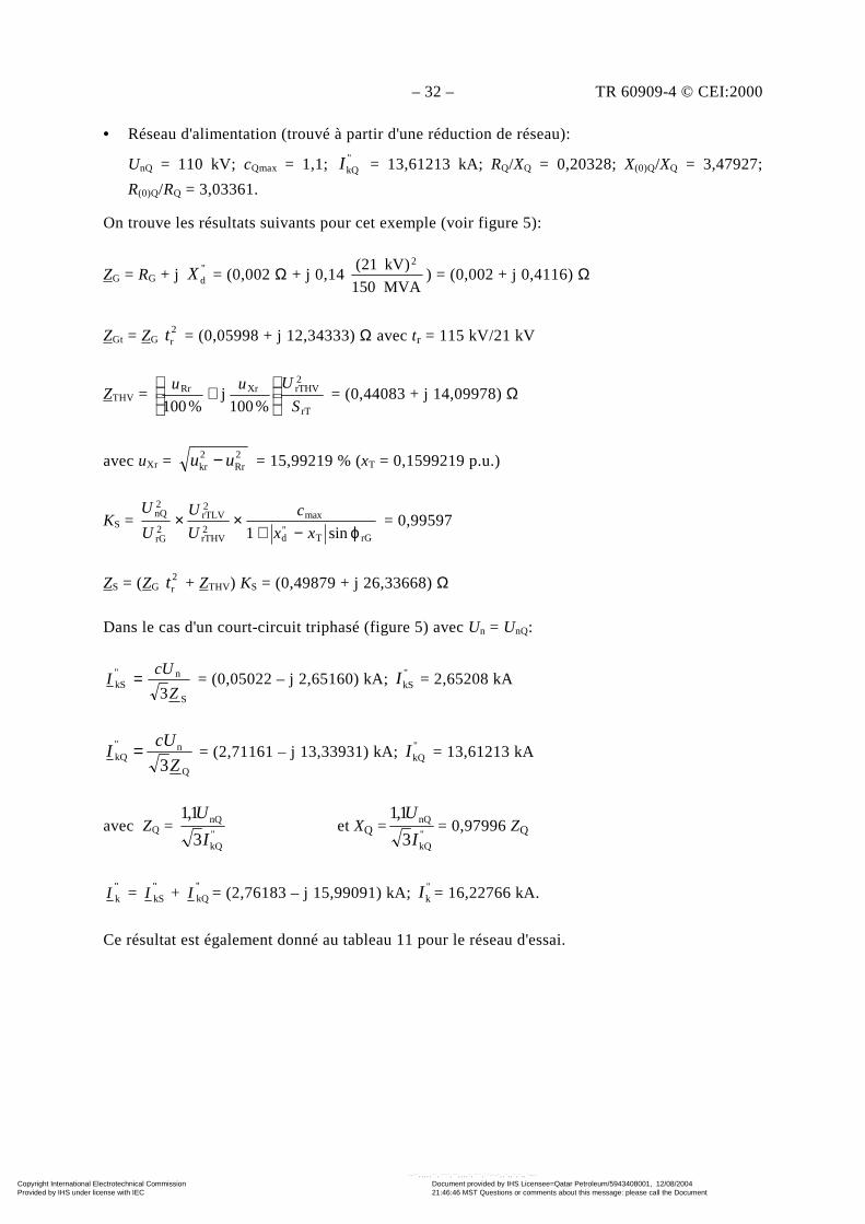
– 32 – TR 60909-4 © CEI:2000
• Réseau d'alimentation (trouvé à partir d'une réduction de réseau):
UnQ = 110 kV; cQmax = 1,1; "kQI = 13,61213 kA; RQ/XQ = 0,20328; X(0)Q/XQ = 3,47927;
R(0)Q/RQ = 3,03361.
On trouve les résultats suivants pour cet exemple (voir figure 5):
ZG = RG + j "dX = (0,002 Ω + j 0,14
MVA150
)kV21( 2
) = (0,002 + j 0,4116) Ω
ZGt = ZG 2rt = (0,05998 + j 12,34333) Ω avec tr = 115 kV/21 kV
ZTHV = rT
2rTHVXrRr
%100j
%100 S
Uuu
+ = (0,44083 + j 14,09978) Ω
avec uXr = 2Rr
2kr uu − = 15,99219 % (xT = 0,1599219 p.u.)
KS = rGT
"d
max
2rTHV
2rTLV
2rG
2nQ
sin1 ϕ−+××
xx
c
U
U
U
U = 0,99597
ZS = (ZG 2rt + ZTHV) KS = (0,49879 + j 26,33668) Ω
Dans le cas d'un court-circuit triphasé (figure 5) avec Un = UnQ:
S
n"kS
3Z
cUI = = (0,05022 – j 2,65160) kA; "kSI = 2,65208 kA
Q
n"kQ
3Z
cUI = = (2,71161 – j 13,33931) kA; "kQI = 13,61213 kA
avec ZQ = "kQ
nQ
3
1,1
I
Uet XQ =
"kQ
nQ
3
1,1
I
U= 0,97996 ZQ
"kI = "
kSI + "kQI = (2,76183 – j 15,99091) kA; "kI = 16,22766 kA.
Ce résultat est également donné au tableau 11 pour le réseau d'essai.
Copyright International Electrotechnical Commission Provided by IHS under license with IEC
Document provided by IHS Licensee=Qatar Petroleum/5943408001, 12/08/200421:46:46 MST Questions or comments about this message: please call the DocumentPolicy Group at 303-397-2295.
--``,,,,,``,````,``,,,,`,```,``-`-`,,`,,`,`,,`---
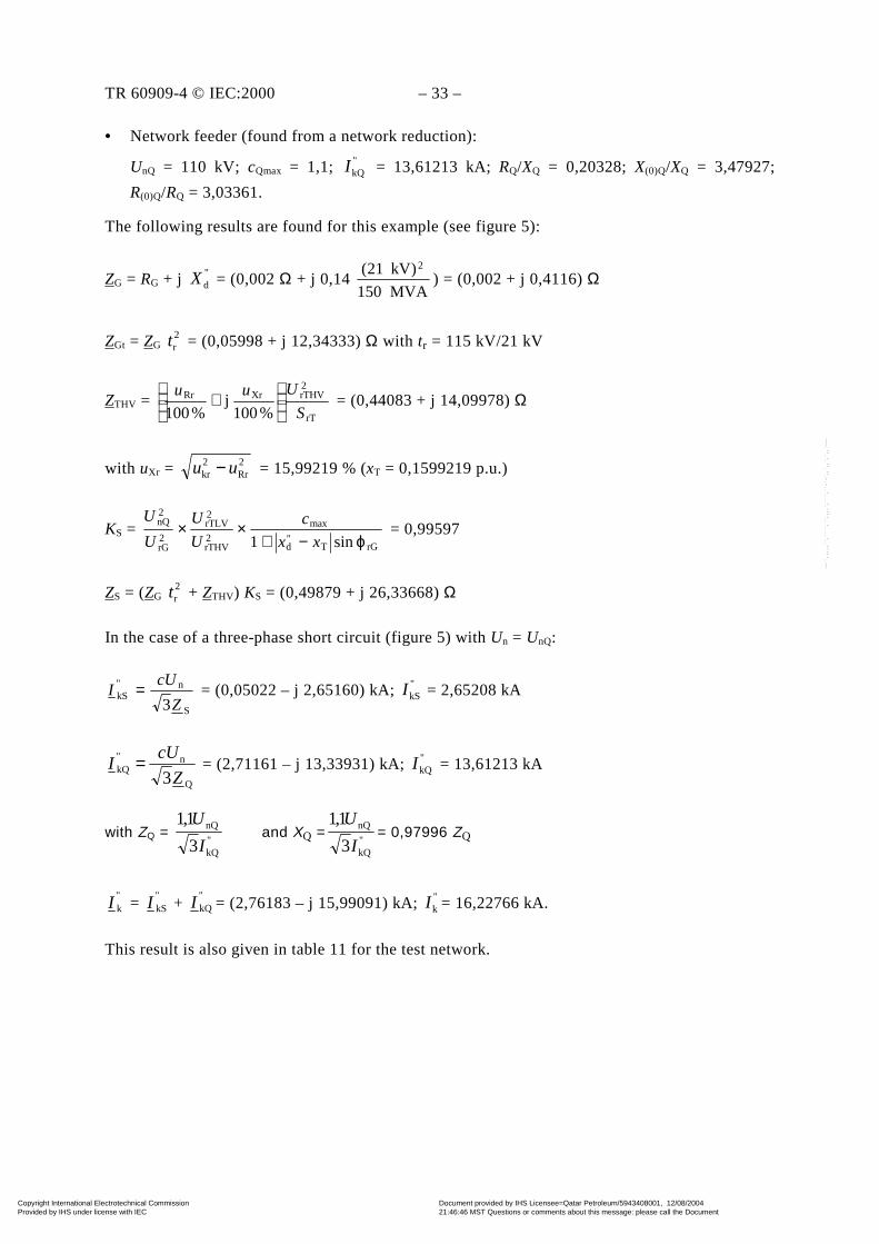
TR 60909-4 © IEC:2000 – 33 –
• Network feeder (found from a network reduction):
UnQ = 110 kV; cQmax = 1,1; "kQI = 13,61213 kA; RQ/XQ = 0,20328; X(0)Q/XQ = 3,47927;
R(0)Q/RQ = 3,03361.
The following results are found for this example (see figure 5):
ZG = RG + j "dX = (0,002 Ω + j 0,14
MVA150
)kV21( 2
) = (0,002 + j 0,4116) Ω
ZGt = ZG 2rt = (0,05998 + j 12,34333) Ω with tr = 115 kV/21 kV
ZTHV = rT
2rTHVXrRr
%100j
%100 S
Uuu
+ = (0,44083 + j 14,09978) Ω
with uXr = 2Rr
2kr uu − = 15,99219 % (xT = 0,1599219 p.u.)
KS = rGT
"d
max
2rTHV
2rTLV
2rG
2nQ
sin1 ϕ−+××
xx
c
U
U
U
U = 0,99597
ZS = (ZG 2rt + ZTHV) KS = (0,49879 + j 26,33668) Ω
In the case of a three-phase short circuit (figure 5) with Un = UnQ:
S
n"kS
3Z
cUI = = (0,05022 – j 2,65160) kA; "kSI = 2,65208 kA
Q
n"kQ
3Z
cUI = = (2,71161 – j 13,33931) kA; "kQI = 13,61213 kA
with ZQ = "kQ
nQ
3
1,1
I
Uand XQ =
"kQ
nQ
3
1,1
I
U= 0,97996 ZQ
"kI =
"kSI +
"kQI = (2,76183 – j 15,99091) kA; "kI = 16,22766 kA.
This result is also given in table 11 for the test network.
Copyright International Electrotechnical Commission Provided by IHS under license with IEC
Document provided by IHS Licensee=Qatar Petroleum/5943408001, 12/08/200421:46:46 MST Questions or comments about this message: please call the DocumentPolicy Group at 303-397-2295.
--``,,,,,``,````,``,,,,`,```,``-`-`,,`,,`,`,,`---
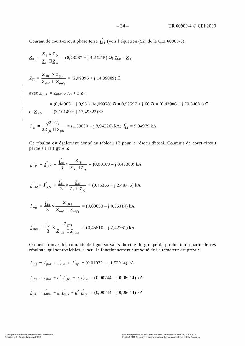
– 34 – TR 60909-4 © CEI:2000
Courant de court-circuit phase terre "1kI (voir l’équation (52) de la CEI 60909-0):
Z(1) = QS
QS
ZZ
ZZ
+×
= (0,73267 + j 4,24215) Ω; Z(2) = Z(1)
Z(0) = (0)Q(0)S
(0)Q(0)S
ZZ
ZZ
+×
= (2,09396 + j 14,39889) Ω
avec Z(0)S = Z(0)THV KS + 3 ZN
= (0,44083 + j 0,95 × 14,09978) Ω × 0,99597 + j 66 Ω = (0,43906 + j 79,34081) Ω
et Z(0)Q = (3,10149 + j 17,49822) Ω
)0()1(
n"k1 2
3
ZZ
UcI
+= = (1,39090 – j 8,94226) kA; "k1I = 9,04979 kA
Ce résultat est également donné au tableau 12 pour le réseau d'essai. Courants de court-circuitpartiels à la figure 5:
"(1)SI = "
(2)SI = QS
Q"k1
3 ZZ
ZI
+× = (0,00109 – j 0,49300) kA
"(1)QI =
"(2)QI =
QS
S"k1
3 ZZ
ZI
+× = (0,46255 – j 2,48775) kA
"(0)SI =
(0)Q(0)S
(0)Q"k1
3 ZZ
ZI
+× = (0,00853 – j 0,55314) kA
"(0)QI =
(0)Q(0)S
(0)S"k1
3 ZZ
ZI
+× = (0,45510 – j 2,42761) kA
On peut trouver les courants de ligne suivants du côté du groupe de production à partir de cesrésultats, qui sont valables, si seul le fonctionnement surexcité de l'alternateur est prévu:
"L1SI =
"(0)SI +
"(1)SI +
"(2)SI = (0,01072 – j 1,53914) kA
"L2SI =
"(0)SI + a2
"(1)SI + a
"(2)SI = (0,00744 – j 0,06014) kA
"L3SI =
"(0)SI + a
"(1)SI + a2
"(2)SI = (0,00744 – j 0,06014) kA
Copyright International Electrotechnical Commission Provided by IHS under license with IEC
Document provided by IHS Licensee=Qatar Petroleum/5943408001, 12/08/200421:46:46 MST Questions or comments about this message: please call the DocumentPolicy Group at 303-397-2295.
--``,,,,,``,````,``,,,,`,```,``-`-`,,`,,`,`,,`---

TR 60909-4 © IEC:2000 – 35 –
Line-to-earth short-circuit current "k1I (see equation (52) of IEC 60909-0):
Z(1) = QS
QS
ZZ
ZZ
+×
= (0,73267 + j 4,24215) Ω; Z(2) = Z(1)
Z(0) = (0)Q(0)S
(0)Q(0)S
ZZ
ZZ
+×
= (2,09396 + j 14,39889) Ω
with Z(0)S = Z(0)THV KS + 3 ZN
= (0,44083 + j 0,95 × 14,09978) Ω × 0,99597 + j 66 Ω = (0,43906 + j 79,34081) Ω
and Z(0)Q = (3,10149 + j 17,49822) Ω
)0()1(
n"k1 2
3
ZZ
UcI
+= = (1,39090 – j 8,94226) kA; "k1I = 9,04979 kA
This result is also given in table 12 for the test network. Partial short-circuit currents in figure 5:
"(1)SI = "
(2)SI = QS
Q"k1
3 ZZ
ZI
+× = (0,00109 – j 0,49300) kA
"(1)QI =
"(2)QI =
QS
S"k1
3 ZZ
ZI
+× = (0,46255 – j 2,48775) kA
"(0)SI =
(0)Q(0)S
(0)Q"k1
3 ZZ
ZI
+× = (0,00853 – j 0,55314) kA
"(0)QI =
(0)Q(0)S
(0)S"k1
3 ZZ
ZI
+× = (0,45510 – j 2,42761) kA
From these results which are valid, if only the overexcited operation of the generator isanticipated, the following line currents at the power-station side can be found:
"L1SI =
"(0)SI +
"(1)SI +
"(2)SI = (0,01072 – j 1,53914) kA
"L2SI =
"(0)SI + a2
"(1)SI + a
"(2)SI = (0,00744 – j 0,06014) kA
"L3SI =
"(0)SI + a
"(1)SI + a2
"(2)SI = (0,00744 – j 0,06014) kA
Copyright International Electrotechnical Commission Provided by IHS under license with IEC
Document provided by IHS Licensee=Qatar Petroleum/5943408001, 12/08/200421:46:46 MST Questions or comments about this message: please call the DocumentPolicy Group at 303-397-2295.
--``,,,,,``,````,``,,,,`,```,``-`-`,,`,,`,`,,`---
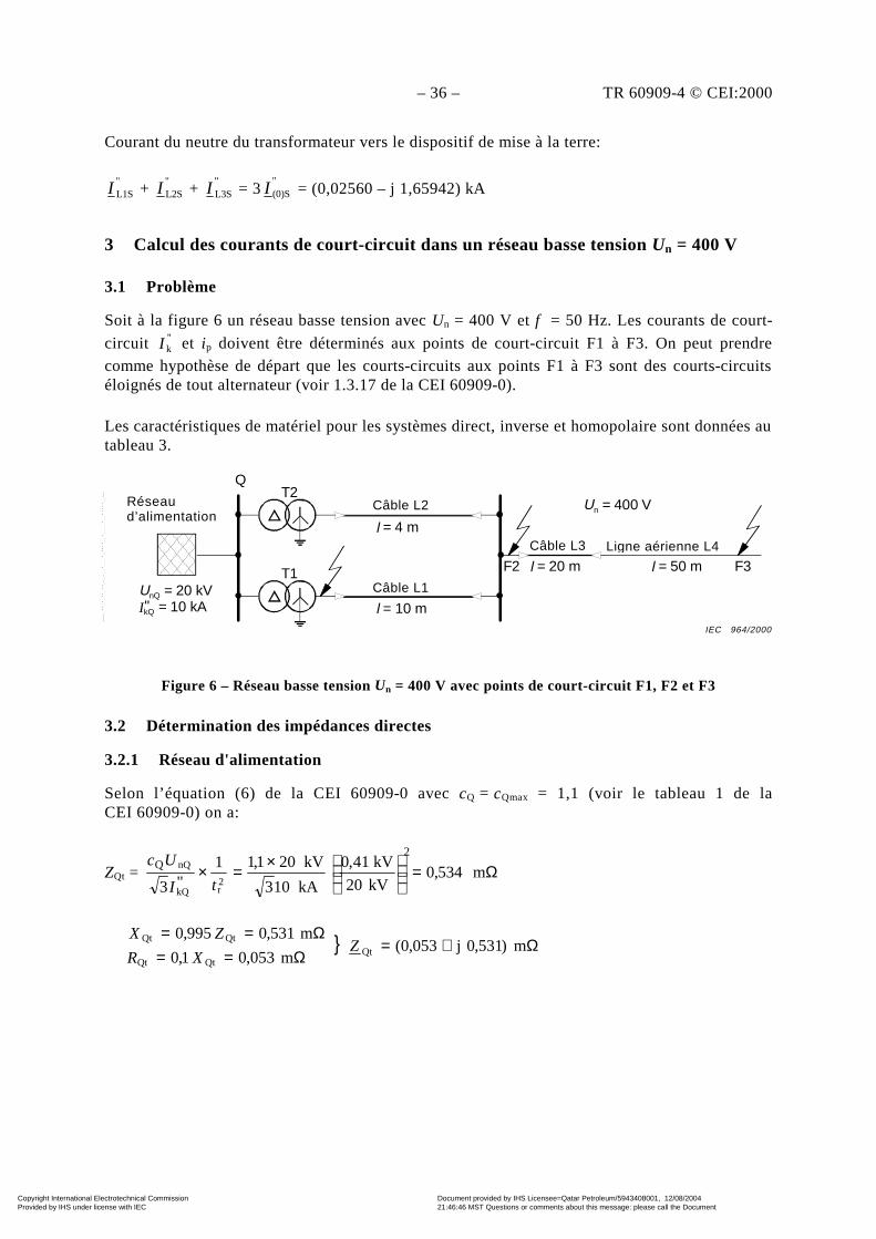
– 36 – TR 60909-4 © CEI:2000
Courant du neutre du transformateur vers le dispositif de mise à la terre:
"L1SI +
"L2SI +
"L3SI = 3
"(0)SI = (0,02560 – j 1,65942) kA
3 Calcul des courants de court-circuit dans un réseau basse tension Un = 400 V
3.1 Problème
Soit à la figure 6 un réseau basse tension avec Un = 400 V et f = 50 Hz. Les courants de court-
circuit "kI et ip doivent être déterminés aux points de court-circuit F1 à F3. On peut prendre
comme hypothèse de départ que les courts-circuits aux points F1 à F3 sont des courts-circuitséloignés de tout alternateur (voir 1.3.17 de la CEI 60909-0).
Les caractéristiques de matériel pour les systèmes direct, inverse et homopolaire sont données autableau 3.
Figure 6 – Réseau basse tension Un = 400 V avec points de court-circuit F1, F2 et F3
3.2 Détermination des impédances directes
3.2.1 Réseau d'alimentation
Selon l’équation (6) de la CEI 60909-0 avec cQ = cQmax = 1,1 (voir le tableau 1 de laCEI 60909-0) on a:
ZQt = Ω=
×=× m534,0kV20
kV41,0
kA103
kV201,11"3
2Q
2rkQ
nQ
tI
Uc
Ω+=Ω==
Ω==m)531,0j053,0(
m053,01,0
m531,0995,0Qt
QtQt
QtQtZ
XR
ZX
T2cable L2
l = 4 m
T1cable L1
l = 10 m
Q
Network feeder
UnQ = 20 kVIkQ = 10 kA"
cable L3
l = 20 m
overhead line L4
l = 50 mF2 F3
Un = 400 VRéseaud’alimentation
Câble L2
Câble L3
Câble L1
Ligne aérienne L4
IEC 964/2000
Copyright International Electrotechnical Commission Provided by IHS under license with IEC
Document provided by IHS Licensee=Qatar Petroleum/5943408001, 12/08/200421:46:46 MST Questions or comments about this message: please call the DocumentPolicy Group at 303-397-2295.
--``,,,,,``,````,``,,,,`,```,``-`-`,,`,,`,`,,`---

TR 60909-4 © IEC:2000 – 37 –
Current from the transformer neutral point to the earthing arrangement:
"L1SI +
"L2SI +
"L3SI = 3
"(0)SI = (0,02560 – j 1,65942) kA
3 Calculation of short-circuit currents in a low-voltage system Un = 400 V
3.1 Problem
A low-voltage system with Un = 400 V and f = 50 Hz is given in figure 6. The short-circuit
currents "kI and ip shall be determined at the short-circuit locations F1 to F3. It may be assumed
that the short circuits at the locations F1 to F3 are far-from-generator short circuits (see 1.3.17 ofIEC 60909-0).
The equipment data for the positive-sequence, the negative-sequence and the zero-sequencesystems are given in table 3.
Figure 6 – Low-voltage system Un = 400 V with short-circuit locations F1, F2 and F3
3.2 Determination of the positive-sequence impedances
3.2.1 Network feeder
According to equation (6) of IEC 60909-0 with cQ = cQmax = 1,1 (see table 1 of IEC 60909-0) itfollows:
ZQt = Ω=
×=× m534,0kV20
kV41,0
kA103
kV201,11"3
2Q
2rkQ
nQ
tI
Uc
Ω+=Ω==
Ω==m)531,0j053,0(
m053,01,0
m531,0995,0Qt
QtQt
QtQtZ
XR
ZX
T2Cable L2l = 4 m
T1Cable L1l = 10 m
Q
Network
UnQ = 20 kVIkQ = 10 kA"
Cable L3l = 20 m
Overhead linel = 50 mF2 F3
Un = 400 V
IEC 964/2000
Copyright International Electrotechnical Commission Provided by IHS under license with IEC
Document provided by IHS Licensee=Qatar Petroleum/5943408001, 12/08/200421:46:46 MST Questions or comments about this message: please call the DocumentPolicy Group at 303-397-2295.
--``,,,,,``,````,``,,,,`,```,``-`-`,,`,,`,`,,`---
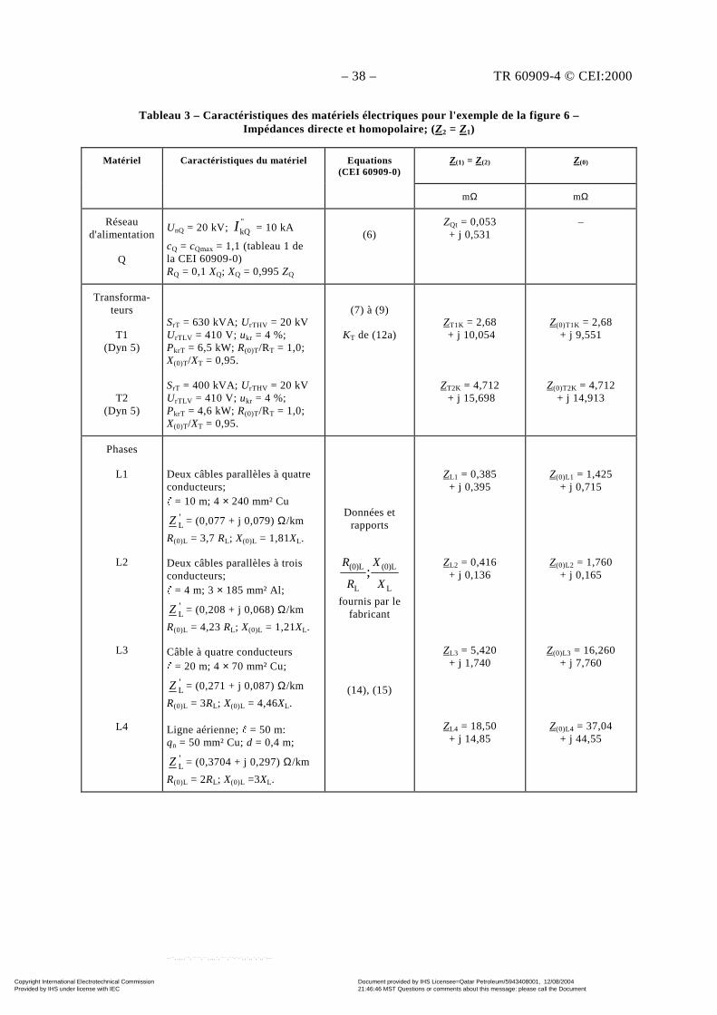
– 38 – TR 60909-4 © CEI:2000
Tableau 3 – Caractéristiques des matériels électriques pour l'exemple de la figure 6 –Impédances directe et homopolaire; (Z2 = Z1)
Matériel Caractéristiques du matériel Equations(CEI 60909-0)
Z(1) = Z(2) Z(0)
mΩ mΩ
Réseaud'alimentation
Q
UnQ = 20 kV; "kQI = 10 kA
cQ = cQmax = 1,1 (tableau 1 dela CEI 60909-0)RQ = 0,1 XQ; XQ = 0,995 ZQ
(6)ZQt = 0,053+ j 0,531
–
Transforma-teurs
T1(Dyn 5)
T2(Dyn 5)
SrT = 630 kVA; UrTHV = 20 kVUrTLV = 410 V; ukr = 4 %;PkrT = 6,5 kW; R(0)T/RT = 1,0;X(0)T/XT = 0,95.
SrT = 400 kVA; UrTHV = 20 kVUrTLV = 410 V; ukr = 4 %;PkrT = 4,6 kW; R(0)T/RT = 1,0;X(0)T/XT = 0,95.
(7) à (9)
KT de (12a)ZT1K = 2,68 + j 10,054
ZT2K = 4,712 + j 15,698
Z(0)T1K = 2,68+ j 9,551
Z(0)T2K = 4,712+ j 14,913
Phases
L1
L2
L3
L4
Deux câbles parallèles à quatreconducteurs;" = 10 m; 4 × 240 mm² Cu
'LZ = (0,077 + j 0,079) Ω/km
R(0)L = 3,7 RL; X(0)L = 1,81XL.
Deux câbles parallèles à troisconducteurs;" = 4 m; 3 × 185 mm² Al;
'LZ = (0,208 + j 0,068) Ω/km
R(0)L = 4,23 RL; X(0)L = 1,21XL.
Câble à quatre conducteurs" = 20 m; 4 × 70 mm² Cu;
'LZ = (0,271 + j 0,087) Ω/km
R(0)L = 3RL; X(0)L = 4,46XL.
Ligne aérienne; " = 50 m:qn = 50 mm² Cu; d = 0,4 m;
'LZ = (0,3704 + j 0,297) Ω/km
R(0)L = 2RL; X(0)L =3XL.
Données etrapports
L
(0)L
L
(0)L ;X
X
R
R
fournis par lefabricant
(14), (15)
ZL1 = 0,385+ j 0,395
ZL2 = 0,416+ j 0,136
ZL3 = 5,420+ j 1,740
ZL4 = 18,50+ j 14,85
Z(0)L1 = 1,425+ j 0,715
Z(0)L2 = 1,760+ j 0,165
Z(0)L3 = 16,260+ j 7,760
Z(0)L4 = 37,04+ j 44,55
Copyright International Electrotechnical Commission Provided by IHS under license with IEC
Document provided by IHS Licensee=Qatar Petroleum/5943408001, 12/08/200421:46:46 MST Questions or comments about this message: please call the DocumentPolicy Group at 303-397-2295.
--``,,,,,``,````,``,,,,`,```,``-`-`,,`,,`,`,,`---
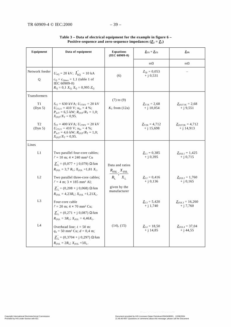
TR 60909-4 © IEC:2000 – 39 –
Table 3 – Data of electrical equipment for the example in figure 6 –Positive-sequence and zero-sequence impedances (Z2 = Z1)
Equipment Data of equipment Equations(IEC 60909-0)
Z(1) = Z(2) Z(0)
mΩ mΩ
Network feeder
Q
UnQ = 20 kV; "kQI = 10 kA
cQ = cQmax = 1,1 (table 1 ofIEC 60909-0)RQ = 0,1 XQ; XQ = 0,995 ZQ
(6)ZQt = 0,053+ j 0,531
–
Transformers
T1(Dyn 5)
T2(Dyn 5)
SrT = 630 kVA; UrTHV = 20 kVUrTLV = 410 V; ukr = 4 %;PkrT = 6,5 kW; R(0)T/RT = 1,0;X(0)T/XT = 0,95.
SrT = 400 kVA; UrTHV = 20 kVUrTLV = 410 V; ukr = 4 %;PkrT = 4,6 kW; R(0)T/RT = 1,0;X(0)T/XT = 0,95.
(7) to (9)
KT from (12a)ZT1K = 2,68 + j 10,054
ZT2K = 4,712 + j 15,698
Z(0)T1K = 2,68+ j 9,551
Z(0)T2K = 4,712+ j 14,913
Lines
L1
L2
L3
L4
Two parallel four-core cables;" = 10 m; 4 × 240 mm² Cu
'LZ = (0,077 + j 0,079) Ω/km
R(0)L = 3,7 RL; X(0)L =1,81 XL.
Two parallel three-core cables;" = 4 m; 3 × 185 mm² Al;
'LZ = (0,208 + j 0,068) Ω/km
R(0)L = 4,23RL; X(0)L =1,21XL.
Four-core cable" = 20 m; 4 × 70 mm² Cu;
'LZ = (0,271 + j 0,087) Ω/km
R(0)L = 3RL; X(0)L = 4,46XL.
Overhead line; " = 50 m:qn = 50 mm² Cu; d = 0,4 m;
'LZ = (0,3704 + j 0,297) Ω/km
R(0)L = 2RL; X(0)L =3XL.
Data and ratios
L
(0)L
L
(0)L ;X
X
R
R
given by themanufacturer
(14), (15)
ZL1 = 0,385+ j 0,395
ZL2 = 0,416+ j 0,136
ZL3 = 5,420+ j 1,740
ZL4 = 18,50+ j 14,85
Z(0)L1 = 1,425+ j 0,715
Z(0)L2 = 1,760+ j 0,165
Z(0)L3 = 16,260+ j 7,760
Z(0)L4 = 37,04+ j 44,55
Copyright International Electrotechnical Commission Provided by IHS under license with IEC
Document provided by IHS Licensee=Qatar Petroleum/5943408001, 12/08/200421:46:46 MST Questions or comments about this message: please call the DocumentPolicy Group at 303-397-2295.
--``,,,,,``,````,``,,,,`,```,``-`-`,,`,,`,`,,`---
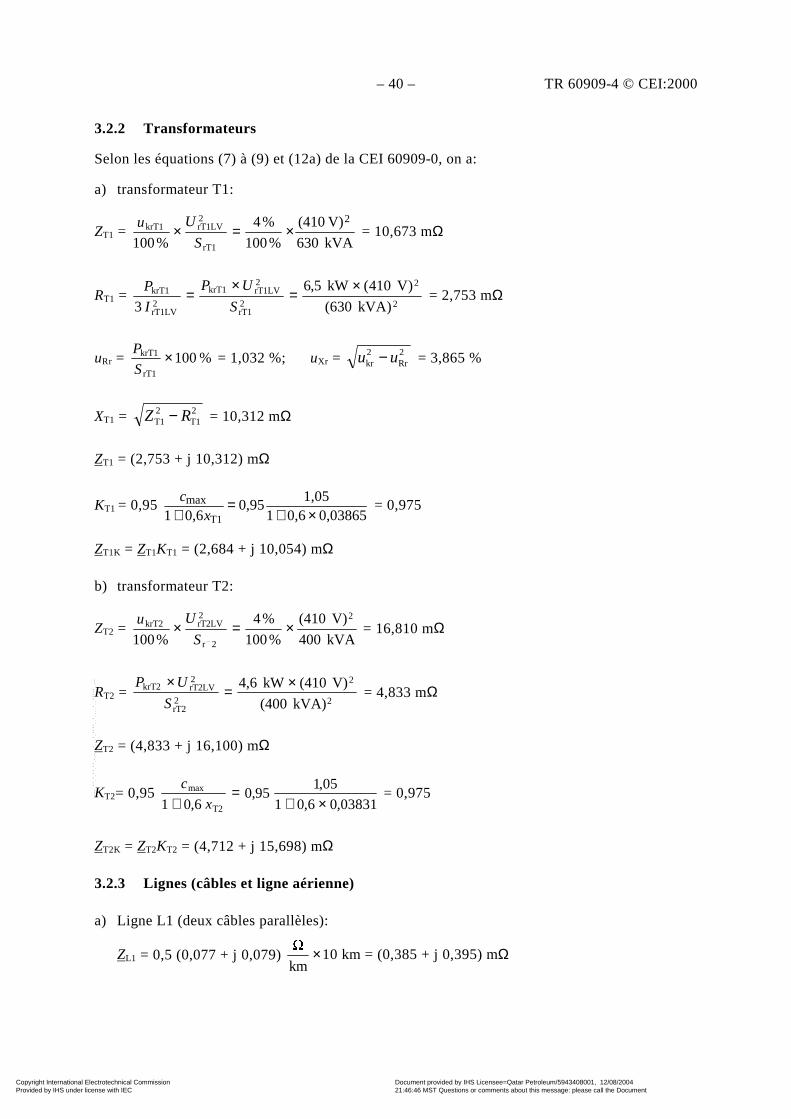
– 40 – TR 60909-4 © CEI:2000
3.2.2 Transformateurs
Selon les équations (7) à (9) et (12a) de la CEI 60909-0, on a:
a) transformateur T1:
ZT1 = kVA630
V)(410
%100
%4
%100
2
rT1
2rT1LVkrT1 ×=×S
Uu = 10,673 mΩ
RT1 = 2
2
2rT1
2rT1LVkrT1
2rT1LV
krT1
)kVA630(
)V410(kW5,6
3
×=×
=S
UP
I
P = 2,753 mΩ
uRr = %100rT1
krT1 ×S
P = 1,032 %; uXr = 2
Rr2kr uu − = 3,865 %
XT1 = 2T1
2T1 RZ − = 10,312 mΩ
ZT1 = (2,753 + j 10,312) mΩ
KT1 = 0,95 0,038650,61
1,050,95
0,61 T1
max×+
=+ xc
= 0,975
ZT1K = ZT1KT1 = (2,684 + j 10,054) mΩ
b) transformateur T2:
ZT2 = kVA400
V)(410
%100
%4
%100
2
2r
2rT2LVkrT2 ×=×S
Uu = 16,810 mΩ
RT2 = 2
2
2rT2
2rT2LVkrT2
kVA)(400
V)(410kW4,6 ×=×S
UP = 4,833 mΩ
ZT2 = (4,833 + j 16,100) mΩ
KT2= 0,95 03831,06,01
05,195,0
6,01 T2
max
×+=
+ x
c = 0,975
ZT2K = ZT2KT2 = (4,712 + j 15,698) mΩ
3.2.3 Lignes (câbles et ligne aérienne)
a) Ligne L1 (deux câbles parallèles):
ZL1 = 0,5 (0,077 + j 0,079) ×km
10 km = (0,385 + j 0,395) mΩ
Copyright International Electrotechnical Commission Provided by IHS under license with IEC
Document provided by IHS Licensee=Qatar Petroleum/5943408001, 12/08/200421:46:46 MST Questions or comments about this message: please call the DocumentPolicy Group at 303-397-2295.
--``,,,,,``,````,``,,,,`,```,``-`-`,,`,,`,`,,`---
TR 60909-4 © IEC:2000 – 41 –
3.2.2 Transformers
According to equations (7) to (9) and (12a) of IEC 60909-0 it follows:
a) Transformer T1:
ZT1 = kVA630
V)(410
%100
%4
%100
2
rT1
2rT1LVkrT1 ×=×S
Uu = 10,673 mΩ
RT1 = 2
2
2rT1
2rT1LVkrT1
2rT1LV
krT1
)kVA630(
)V410(kW5,6
3
×=×
=S
UP
I
P = 2,753 mΩ
uRr = %100rT1
krT1 ×S
P = 1,032 %; uXr = 2
Rr2kr uu − = 3,865 %
XT1 = 2T1
2T1 RZ − = 10,312 mΩ
ZT1 = (2,753 + j 10,312) mΩ
KT1 = 0,95 0,038650,61
1,050,95
0,61 T1
max×+
=+ xc
= 0,975
ZT1K = ZT1KT1 = (2,684 + j 10,054) mΩ
b) Transformer T2:
ZT2 = kVA400
V)(410
%100
%4
%100
2
2r
2rT2LVkrT2 ×=×S
Uu = 16,810 mΩ
RT2 = 2
2
2rT2
2rT2LVkrT2
kVA)(400
V)(410kW4,6 ×=×S
UP = 4,833 mΩ
ZT2 = (4,833 + j 16,100) mΩ
KT2= 0,95 03831,06,01
05,195,0
6,01 T2
max
×+=
+ x
c = 0,975
ZT2K = ZT2KT2 = (4,712 + j 15,698) mΩ
3.2.3 Lines (cables and overhead lines)
a) Line L1 (two parallel cables):
ZL1 = 0,5 (0,077 + j 0,079) ×km
10 km = (0,385 + j 0,395) mΩ
Copyright International Electrotechnical Commission Provided by IHS under license with IEC
Document provided by IHS Licensee=Qatar Petroleum/5943408001, 12/08/200421:46:46 MST Questions or comments about this message: please call the DocumentPolicy Group at 303-397-2295.
--``,,,,,``,````,``,,,,`,```,``-`-`,,`,,`,`,,`---

– 42 – TR 60909-4 © CEI:2000
b) Ligne L2 (deux câbles parallèles):
ZL2 = 0,5 (0,208 + j 0,068) ×km
4 m = (0,416 + j 0,136) mΩ
c) Ligne L3 (câble):
ZL3 = (0,271 + j 0,087) ×km
20 m = (5,420 + j 1,740) mΩ
d) Ligne L4 (ligne aérienne):
;mm55,4
14,1;km
3704,0
mm50m54
mm n
2
2
n
'L4 ===
×=ρ= q
rq
R
km
297,0
m10455,0
m4,0ln
4
1
kmA2
Vs104s502ln
4
1
2f2
2
410'
L4 =
×
+π×π
×π=
+
πµπ=
−
−−
r
dX
ZL4 = ( ")j 'L4
'L4 XR + = (0,370 + j 0,297) × ×Ω
km50 m = (18,50 + j 14,85) mΩ
3.3 Détermination des impédances homopolaires
3.3.1 Transformateurs
Pour les transformateurs T1 et T2 de couplage Dyn5, les constructeurs donnent les relationssuivantes:
R(0)T = RT et X(0)T = 0,95 XT (voir tableau 3)
Avec les facteurs de correction d'impédance KT de 3.2.2, on obtient les impédances homopolairessuivantes pour les transformateurs:
Z(0)T1K = (RT1 + j 0,95 XT1)KT1 = (2,684 + j 9,551) mΩ
Z(0)T2K = (RT2 + j 0,95 XT2)KT2 = (4,712 + j 14,913) mΩ
3.3.2 Lignes (câbles et lignes aériennes)
a) Ligne L1:
R(0)L = 3,7 RL; X(0)L = 1,81 XL avec retour par le quatrième conducteur et conducteur péri-phérique:
Z(0)L1 = (3,7 RL1 + j 1,81 XL1) = (1,425 + j 0,715) mΩ
b) Ligne L2:
R(0)L = 4,23 RL; X(0)L = 1,21 XL avec retour par la gaine:
Z(0)L2 = (4,23 RL2 + j 1,21 XL2) = (1,760 + j 0,165) mΩ
c) Ligne L3:
R(0)L = 3 RL; X(0)L = 4,46 XL avec retour par le quatrième conducteur, par la gaine et la terre:
Z(0)L3 = (3 RL3 + j 4,46 XL3) = (16,260 + j 7,760) mΩ
Copyright International Electrotechnical Commission Provided by IHS under license with IEC
Document provided by IHS Licensee=Qatar Petroleum/5943408001, 12/08/200421:46:46 MST Questions or comments about this message: please call the DocumentPolicy Group at 303-397-2295.
--``,,,,,``,````,``,,,,`,```,``-`-`,,`,,`,`,,`---
TR 60909-4 © IEC:2000 – 43 –
b) Line L2 (two parallel cables):
ZL2 = 0,5 (0,208 + j 0,068) ×km
4 m = (0,416 + j 0,136) mΩ
c) Line L3 (cable):
ZL3 = (0,271 + j 0,087) ×km
20 m = (5,420 + j 1,740) mΩ
d) Line L4 (overhead line):
;mm55,4
14,1;km
3704,0
mm50m54
mm n
2
2
n
'L4 ===
×=ρ= q
rq
R
km
297,0
m10455,0
m4,0ln
4
1
kmA2
Vs104s502ln
4
1
2f2
2
410'
L4 =
×
+π×π
×π=
+
πµπ=
−
−−
r
dX
ZL4 = ( ")j 'L4
'L4 XR + = (0,370 + j 0,297) × ×Ω
km50 m = (18,50 + j 14,85) mΩ
3.3 Determination of the zero-sequence impedances
3.3.1 Transformers
For the transformers T1 and T2 with the vector group Dyn5 the following relations are given bythe manufacturers:
R(0)T = RT and X(0)T = 0,95 XT (see table 3)
Together with the impedance correction factors KT from 3.2.2, the following zero-sequenceimpedances of the transformers are found:
Z(0)T1K = (RT1 + j 0,95 XT1)KT1 = (2,684 + j 9,551) mΩ
Z(0)T2K = (RT2 + j 0,95 XT2)KT2 = (4,712 + j 14,913) mΩ
3.3.2 Lines (cables and overhead lines)
a) Line L1:
R(0)L = 3,7 RL; X(0)L = 1,81 XL with return circuit by the fourth conductor and surroundingconductor:
Z(0)L1 = (3,7 RL1 + j 1,81 XL1) = (1,425 + j 0,715) mΩ
b) Line L2:
R(0)L = 4,23 RL; X(0)L = 1,21 XL with return by sheath:
Z(0)L2 = (4,23 RL2 + j 1,21 XL2) = (1,760 + j 0,165) mΩ
c) Line L3:
R(0)L = 3 RL; X(0)L = 4,46 XL with return circuit by the fourth conductor, sheath and earth:
Z(0)L3 = (3 RL3 + j 4,46 XL3) = (16,260 + j 7,760) mΩ
Copyright International Electrotechnical Commission Provided by IHS under license with IEC
Document provided by IHS Licensee=Qatar Petroleum/5943408001, 12/08/200421:46:46 MST Questions or comments about this message: please call the DocumentPolicy Group at 303-397-2295.
--``,,,,,``,````,``,,,,`,```,``-`-`,,`,,`,`,,`---
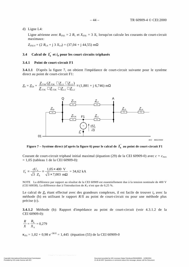
– 44 – TR 60909-4 © CEI:2000
d) Ligne L4:
Ligne aérienne avec R(0)L = 2 RL et X(0)L = 3 XL lorsqu'on calcule les courants de court-circuitmaximaux:
Z(0)L4 = (2 RL4 + j 3 XL4) = (37,04 + j 44,55) mΩ
3.4 Calcul de "kI et ip pour les court circuits triphasés
3.4.1 Point de court-circuit F1
3.4.1.1 D'après la figure 7, on obtient l'impédance de court-circuit suivante pour le systèmedirect au point de court-circuit F1:
Zk = ZQt + =+++
++L2L1T2KT1K
L2L1T2KT1K )(ZZZZ
ZZZZ(1,881 + j 6,746) mΩ
Figure 7 – Système direct (d'après la figure 6) pour le calcul de "kI au point de court-circuit F1
Courant de court-circuit triphasé initial maximal (équation (29) de la CEI 60909-0) avec c = cmax
= 1,05 (tableau 1 de la CEI 60909-0):
m 7,0033
V4001,05
3 k
n"k
××==
Z
UcI = 34,62 kA
NOTE La différence par rapport au résultat de la CEI 60909 est essentiellement due à la tension nominale de 400 V(CEI 60038). La différence due à l'introduction de KT n'est que de 0,25 %.
Le calcul de Zk étant effectué avec des grandeurs complexes, il est facile de trouver ip avec laméthode (b) en utilisant le rapport R/X au point de court-circuit ou pour une méthode plusprécise (c).
3.4.1.2 Méthode (b): Rapport d'impédance au point de court-circuit (voir 4.3.1.2 de laCEI 60909-0):
279,0==k
k
X
R
X
R
κ(b) = 1,02 + 0,98 e–3R/X = 1,445 (équation (55) de la CEI 60909-0
~
~ ~
~ ~
~ ~ZQt
ZT2K
ZT1K ZL1F1
Q AZL2
ZL3 ZL4
Ik"
cUn
√3
01
~
IEC 965/2000
Copyright International Electrotechnical Commission Provided by IHS under license with IEC
Document provided by IHS Licensee=Qatar Petroleum/5943408001, 12/08/200421:46:46 MST Questions or comments about this message: please call the DocumentPolicy Group at 303-397-2295.
--``,,,,,``,````,``,,,,`,```,``-`-`,,`,,`,`,,`---
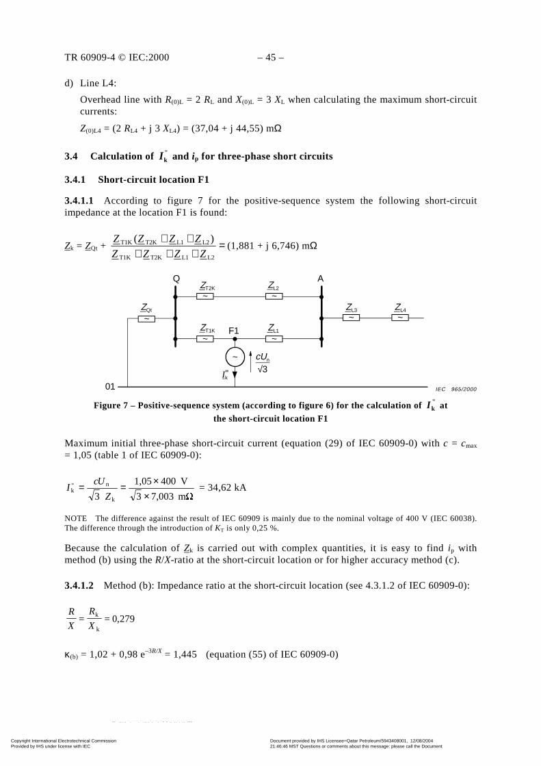
TR 60909-4 © IEC:2000 – 45 –
d) Line L4:
Overhead line with R(0)L = 2 RL and X(0)L = 3 XL when calculating the maximum short-circuitcurrents:
Z(0)L4 = (2 RL4 + j 3 XL4) = (37,04 + j 44,55) mΩ
3.4 Calculation of "kI and ip for three-phase short circuits
3.4.1 Short-circuit location F1
3.4.1.1 According to figure 7 for the positive-sequence system the following short-circuitimpedance at the location F1 is found:
Zk = ZQt + =+++
++L2L1T2KT1K
L2L1T2KT1K )(ZZZZ
ZZZZ(1,881 + j 6,746) mΩ
Figure 7 – Positive-sequence system (according to figure 6) for the calculation of "kI at
the short-circuit location F1
Maximum initial three-phase short-circuit current (equation (29) of IEC 60909-0) with c = cmax
= 1,05 (table 1 of IEC 60909-0):
m 7,0033
V4001,05
3 k
n"k
××==
Z
UcI = 34,62 kA
NOTE The difference against the result of IEC 60909 is mainly due to the nominal voltage of 400 V (IEC 60038).The difference through the introduction of KT is only 0,25 %.
Because the calculation of Zk is carried out with complex quantities, it is easy to find ip withmethod (b) using the R/X-ratio at the short-circuit location or for higher accuracy method (c).
3.4.1.2 Method (b): Impedance ratio at the short-circuit location (see 4.3.1.2 of IEC 60909-0):
279,0==k
k
X
R
X
R
κ(b) = 1,02 + 0,98 e–3R/X = 1,445 (equation (55) of IEC 60909-0)
~
~ ~
~ ~
~ ~ZQt
ZT2K
ZT1K ZL1F1
Q AZL2
ZL3 ZL4
Ik"
cUn
√3
01
~
IEC 965/2000
Copyright International Electrotechnical Commission Provided by IHS under license with IEC
Document provided by IHS Licensee=Qatar Petroleum/5943408001, 12/08/200421:46:46 MST Questions or comments about this message: please call the DocumentPolicy Group at 303-397-2295.
--``,,,,,``,````,``,,,,`,```,``-`-`,,`,,`,`,,`---
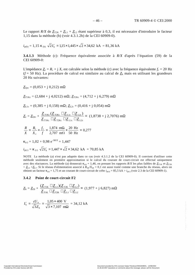
– 46 – TR 60909-4 © CEI:2000
Le rapport R/X de ZT2K + ZL1 + ZL2 étant supérieur à 0,3, il est nécessaire d'introduire le facteur1,15 dans la méthode (b) (voir 4.3.1.2b) de la CEI 60909-0).
ip(b) = 1,15 κ (b) kA62,342445,115,12 "k ×××=I = 81,36 kA
3.4.1.3 Méthode (c): Fréquence équivalente associée à R/X d'après l’équation (59) de laCEI 60909-0:
L'impédance Zc = Rc + j Xc est calculée selon la méthode (c) avec la fréquence équivalente fc = 20 Hz(f = 50 Hz). La procédure de calcul est similaire au calcul de Zk mais en utilisant les grandeurs20 Hz suivantes:
ZQtc = (0,053 + j 0,212) mΩ
ZT1Kc = (2,684 + j 4,0212) mΩ; ZT2Kc = (4,712 + j 6,279) mΩ
ZL1c = (0,385 + j 0,158) mΩ; ZL2c = (0,416 + j 0,054) mΩ
Zc = ZQtc + =+++
++L2cL1cT2KcT1Kc
L2cL1cT2KcT1Kc )(
ZZZZ
ZZZZ (1,8738 + j 2,7076) mΩ
0,277Hz50
Hz20
m 2,707
m 1,874c
c
c =×=×=f
f
X
R
X
R
κ(c) = 1,02 + 0,98 e-3R/X = 1,447
ip(c) = κ (c) kA34,6221,4472 "k ××=I = 70,85 kA
NOTE La méthode (a) n'est pas adaptée dans ce cas (voir 4.3.1.2 de la CEI 60909-0). Il convient d'utiliser cetteméthode seulement en première approximation si le calcul du courant de court-circuit est effectué uniquementavec des réactances. La méthode (a) donnerait κ(a) = 1,46, en prenant les rapports R/X les plus faibles de ZT1K et ZT2K
+ ZL2 +ZL1. Si le réseau d'alimentation associé à RQt/XQt = 0,1 est aussi traité comme une branche du réseau, alors onobtient un facteur κ(a) = 1,75 et un courant de court-circuit de crête ip(a) = 85,5 kA > ip(c) (voir 2.3 de la CEI 60909-1).
3.4.2 Point de court-circuit F2
Zk = ZQt + =+++++
L2L1T2KT1K
L2T2KL1T1K ))((ZZZZ
ZZZZ (1,977 + j 6,827) mΩ
m 7,1073
V4001,05
3 k
n"k
××==
Z
UcI = 34,12 kA
Copyright International Electrotechnical Commission Provided by IHS under license with IEC
Document provided by IHS Licensee=Qatar Petroleum/5943408001, 12/08/200421:46:46 MST Questions or comments about this message: please call the DocumentPolicy Group at 303-397-2295.
--``,,,,,``,````,``,,,,`,```,``-`-`,,`,,`,`,,`---
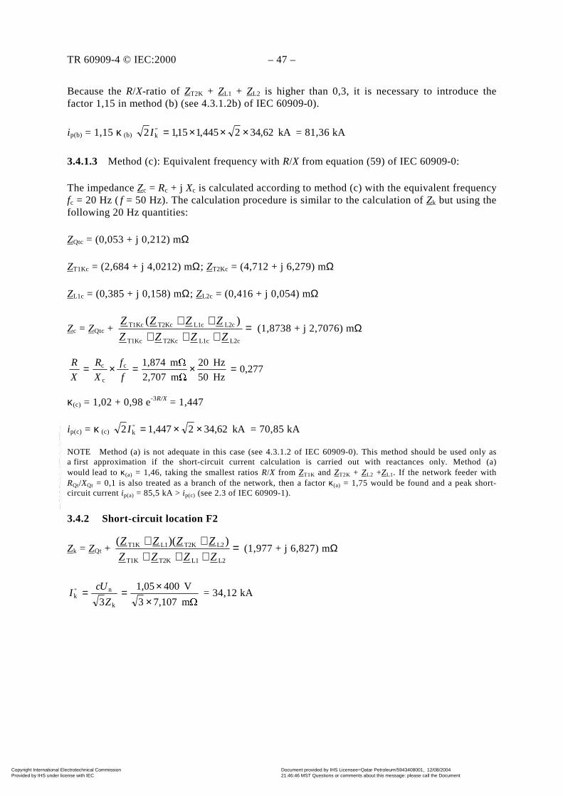
TR 60909-4 © IEC:2000 – 47 –
Because the R/X-ratio of ZT2K + ZL1 + ZL2 is higher than 0,3, it is necessary to introduce thefactor 1,15 in method (b) (see 4.3.1.2b) of IEC 60909-0).
ip(b) = 1,15 κ (b) kA62,342445,115,12 "k ×××=I = 81,36 kA
3.4.1.3 Method (c): Equivalent frequency with R/X from equation (59) of IEC 60909-0:
The impedance Zc = Rc + j Xc is calculated according to method (c) with the equivalent frequencyfc = 20 Hz (f = 50 Hz). The calculation procedure is similar to the calculation of Zk but using thefollowing 20 Hz quantities:
ZQtc = (0,053 + j 0,212) mΩ
ZT1Kc = (2,684 + j 4,0212) mΩ; ZT2Kc = (4,712 + j 6,279) mΩ
ZL1c = (0,385 + j 0,158) mΩ; ZL2c = (0,416 + j 0,054) mΩ
Zc = ZQtc + =+++
++
L2cL1cT2KcT1Kc
L2cL1cT2KcT1Kc )(
ZZZZ
ZZZZ (1,8738 + j 2,7076) mΩ
0,277Hz50
Hz20
m 2,707
m 1,874c
c
c =×=×=f
f
X
R
X
R
κ(c) = 1,02 + 0,98 e-3R/X = 1,447
ip(c) = κ (c) kA34,6221,4472 "k ××=I = 70,85 kA
NOTE Method (a) is not adequate in this case (see 4.3.1.2 of IEC 60909-0). This method should be used only asa first approximation if the short-circuit current calculation is carried out with reactances only. Method (a)would lead to κ(a) = 1,46, taking the smallest ratios R/X from ZT1K and ZT2K + ZL2 +ZL1. If the network feeder withRQt/XQt = 0,1 is also treated as a branch of the network, then a factor κ(a) = 1,75 would be found and a peak short-circuit current ip(a) = 85,5 kA > ip(c) (see 2.3 of IEC 60909-1).
3.4.2 Short-circuit location F2
Zk = ZQt + =+++++
L2L1T2KT1K
L2T2KL1T1K ))((ZZZZ
ZZZZ (1,977 + j 6,827) mΩ
m 7,1073
V4001,05
3 k
n"k
××==
Z
UcI = 34,12 kA
Copyright International Electrotechnical Commission Provided by IHS under license with IEC
Document provided by IHS Licensee=Qatar Petroleum/5943408001, 12/08/200421:46:46 MST Questions or comments about this message: please call the DocumentPolicy Group at 303-397-2295.
--``,,,,,``,````,``,,,,`,```,``-`-`,,`,,`,`,,`---

– 48 – TR 60909-4 © CEI:2000
Le calcul avec la méthode (c) (voir 4.3.1.2 de la CEI 60909-0) donne:
Zc = (1,976 + j 2,733) mΩ
0,289Hz50
Hz20
m 2,733
m 1,976c
c
c =×=×=f
f
X
R
X
R
ip(c) = κ (c) kA12,342432,12 "k ××=I = 69,10 kA
NOTE Le rapport qui est significatif R/X est essentiellement déterminé par les rapports des deux branchesZT1K + ZL1 et ZT2K + ZL2 associée à R/X = 0,294 et 0,324. Ces deux rapports sont similaires à Rk/Xk ≈ 0,29 donnantκ(b) = 1,431. Le calcul avec la méthode (b), mais sans le facteur complémentaire 1,15, donne
ip(b) = κ(b) kA12,34×2×4311,="2 kI = 69,05 kA
3.4.3 Point de court-circuit F3
Zk = ZQt + =+++++++
4L3LL2L1T2KT1K
L2T2KL1T1K )()(ZZ
ZZZZ
ZZZZ (25,897 + j 23,417) mΩ
m 914,343
V40005,1
3 k
n"k
××==
Z
UcI = 6,95 kA
Zc = ZF2c + ZL3c + ZL4c = (1,976 + j 2,733) mΩ + (23,920 + j 6,636) mΩ
106,1Hz50
Hz20
m 9,369
m 25,896c
c
c =×=×=f
f
X
R
X
R
ip(c) = κ(c) kA6,952056,12 "k ××=I = 10,38 kA
3.5 Calcul de "k1I et ip1 pour les courts-circuits phase terre
3.5.1 Point de court-circuit F1
La figure 8 donne le circuit équivalent dans les systèmes direct, inverse et homopolaire duréseau représenté à la figure 6 avec un court-circuit phase terre en F1.
Z(1) = Z(2) = Zk = (1,881 + j 6,764) mΩ (voir 3.4.1)
Z(0) = =+++
++
2L)0(1L)0(K2T)0(K1T)0(
2L)0(1L)0(K2T)0(K1T)0( )(
ZZZZ
ZZZZ(2,140 + j 6,009) mΩ
Z(1) + Z(2) + Z(0) = 2 Z(1) + Z(0) = (5,902 + j 19,537) mΩ
Copyright International Electrotechnical Commission Provided by IHS under license with IEC
Document provided by IHS Licensee=Qatar Petroleum/5943408001, 12/08/200421:46:46 MST Questions or comments about this message: please call the DocumentPolicy Group at 303-397-2295.
--``,,,,,``,````,``,,,,`,```,``-`-`,,`,,`,`,,`---
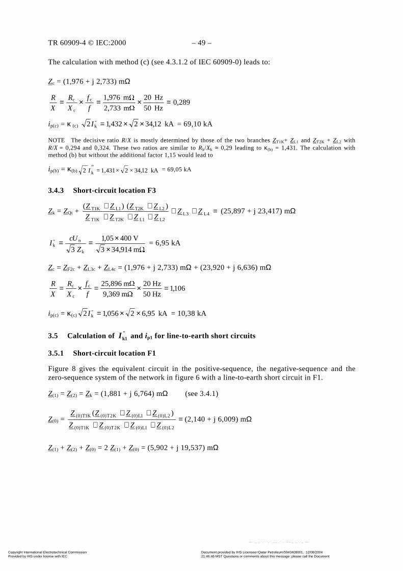
TR 60909-4 © IEC:2000 – 49 –
The calculation with method (c) (see 4.3.1.2 of IEC 60909-0) leads to:
Zc = (1,976 + j 2,733) mΩ
0,289Hz50
Hz20
m 2,733
m 1,976c
c
c =×=×=f
f
X
R
X
R
ip(c) = κ (c) kA12,342432,12 "k ××=I = 69,10 kA
NOTE The decisive ratio R/X is mostly determined by those of the two branches ZT1K+ ZL1 and ZT2K + ZL2 withR/X = 0,294 and 0,324. These two ratios are similar to Rk/Xk ≈ 0,29 leading to κ(b) = 1,431. The calculation withmethod (b) but without the additional factor 1,15 would lead to
ip(b) = κ(b) kA12,34×2×4311,="2 kI = 69,05 kA
3.4.3 Short-circuit location F3
Zk = ZQt + =+++++++
4L3LL2L1T2KT1K
L2T2KL1T1K )()(ZZ
ZZZZ
ZZZZ (25,897 + j 23,417) mΩ
m 914,343
V40005,1
3 k
n"k
××==
Z
UcI = 6,95 kA
Zc = ZF2c + ZL3c + ZL4c = (1,976 + j 2,733) mΩ + (23,920 + j 6,636) mΩ
106,1Hz50
Hz20
m 9,369
m 25,896c
c
c =×=×=f
f
X
R
X
R
ip(c) = κ(c) kA6,952056,12 "k ××=I = 10,38 kA
3.5 Calculation of "k1I and ip1 for line-to-earth short circuits
3.5.1 Short-circuit location F1
Figure 8 gives the equivalent circuit in the positive-sequence, the negative-sequence and thezero-sequence system of the network in figure 6 with a line-to-earth short circuit in F1.
Z(1) = Z(2) = Zk = (1,881 + j 6,764) mΩ (see 3.4.1)
Z(0) = =+++
++
2L)0(1L)0(K2T)0(K1T)0(
2L)0(1L)0(K2T)0(K1T)0( )(
ZZZZ
ZZZZ(2,140 + j 6,009) mΩ
Z(1) + Z(2) + Z(0) = 2 Z(1) + Z(0) = (5,902 + j 19,537) mΩ
Copyright International Electrotechnical Commission Provided by IHS under license with IEC
Document provided by IHS Licensee=Qatar Petroleum/5943408001, 12/08/200421:46:46 MST Questions or comments about this message: please call the DocumentPolicy Group at 303-397-2295.
--``,,,,,``,````,``,,,,`,```,``-`-`,,`,,`,`,,`---
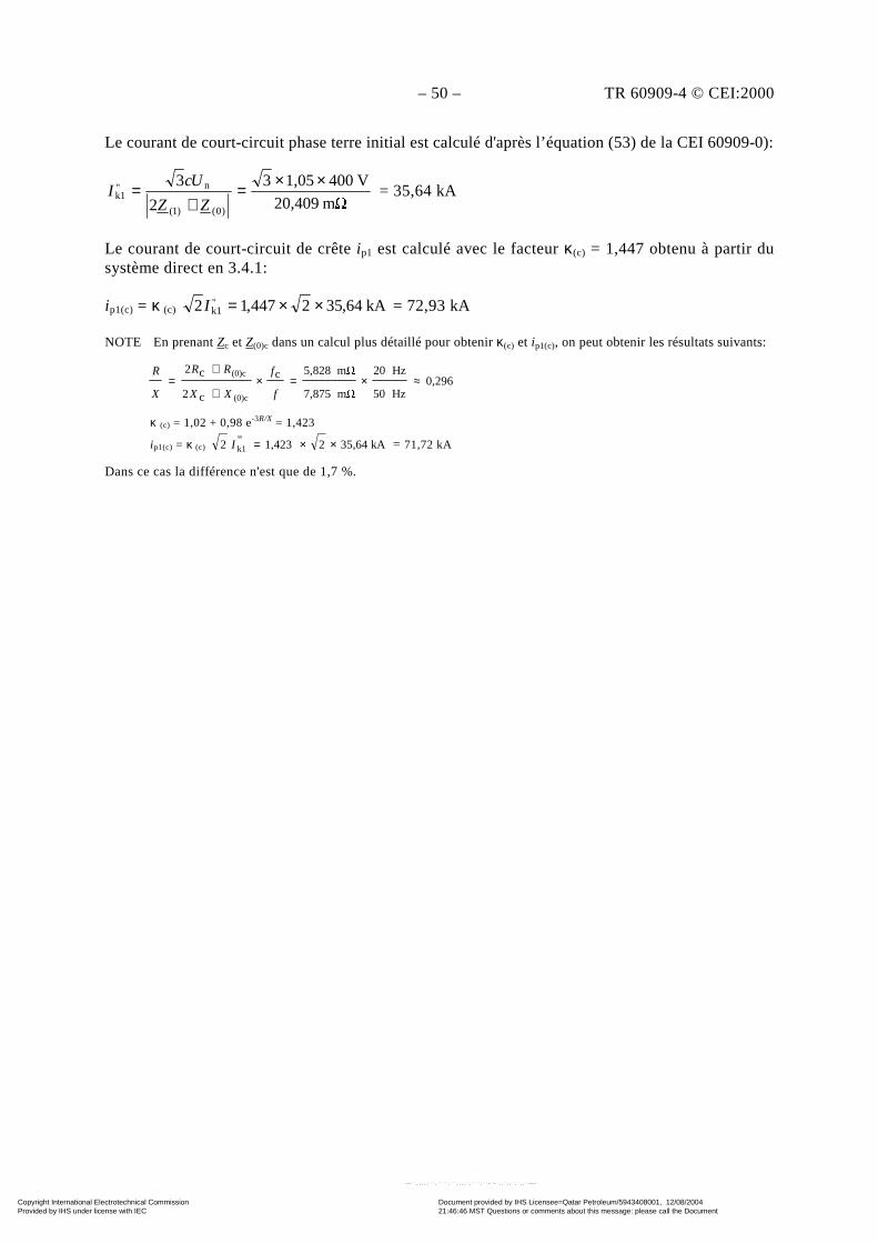
– 50 – TR 60909-4 © CEI:2000
Le courant de court-circuit phase terre initial est calculé d'après l’équation (53) de la CEI 60909-0):
m 20,409
V4001,053
2
3
)0()1(
n"k1
××=+
=ZZ
UcI = 35,64 kA
Le courant de court-circuit de crête ip1 est calculé avec le facteur κ(c) = 1,447 obtenu à partir dusystème direct en 3.4.1:
ip1(c) = κ (c) kA64,352447,12 "k1 ××=I = 72,93 kA
NOTE En prenant Zc et Z(0)c dans un calcul plus détaillé pour obtenir κ(c) et ip1(c), on peut obtenir les résultats suivants:
0,296Hz50
Hz20
m 7,875
m 5,828c
c2
c2
(0)c
(0)c≈×=×
+
+=
f
f
XX
RR
X
R
κ (c) = 1,02 + 0,98 e-3R/X = 1,423
ip1(c) = κ (c) kA35,6421,423"2 k1 ××=I = 71,72 kA
Dans ce cas la différence n'est que de 1,7 %.
Copyright International Electrotechnical Commission Provided by IHS under license with IEC
Document provided by IHS Licensee=Qatar Petroleum/5943408001, 12/08/200421:46:46 MST Questions or comments about this message: please call the DocumentPolicy Group at 303-397-2295.
--``,,,,,``,````,``,,,,`,```,``-`-`,,`,,`,`,,`---
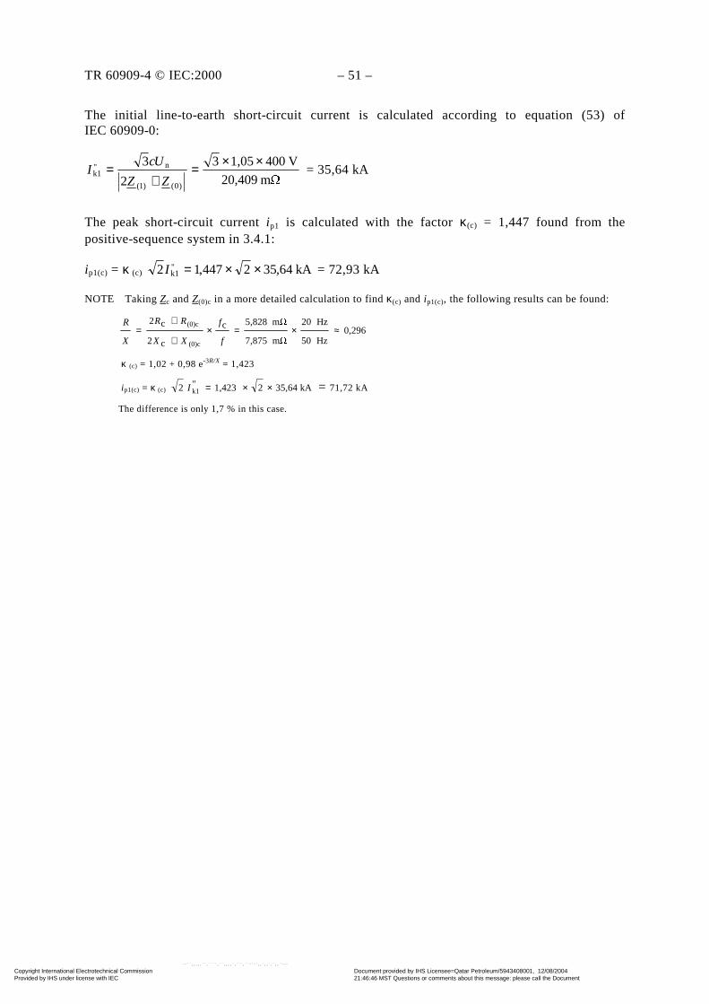
TR 60909-4 © IEC:2000 – 51 –
The initial line-to-earth short-circuit current is calculated according to equation (53) ofIEC 60909-0:
m 20,409
V4001,053
2
3
)0()1(
n"k1
××=+
=ZZ
UcI = 35,64 kA
The peak short-circuit current ip1 is calculated with the factor κ(c) = 1,447 found from thepositive-sequence system in 3.4.1:
ip1(c) = κ (c) kA64,352447,12 "k1 ××=I = 72,93 kA
NOTE Taking Zc and Z(0)c in a more detailed calculation to find κ(c) and ip1(c), the following results can be found:
0,296Hz50
Hz20
m 7,875
m 5,828c
c2
c2
(0)c
(0)c≈×=×
+
+=
f
f
XX
RR
X
R
κ (c) = 1,02 + 0,98 e-3R/X = 1,423
ip1(c) = κ (c) kA35,6421,423"2 k1 ××=I = 71,72 kA
The difference is only 1,7 % in this case.
Copyright International Electrotechnical Commission Provided by IHS under license with IEC
Document provided by IHS Licensee=Qatar Petroleum/5943408001, 12/08/200421:46:46 MST Questions or comments about this message: please call the DocumentPolicy Group at 303-397-2295.
--``,,,,,``,````,``,,,,`,```,``-`-`,,`,,`,`,,`---
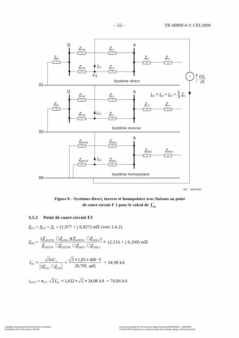
– 52 – TR 60909-4 © CEI:2000
Figure 8 – Systèmes direct, inverse et homopolaire avec liaisons au point
de court-circuit F 1 pour le calcul de "k1I
3.5.2 Point de court-circuit F2
Z(1) = Z(2) = Zk = (1,977 + j 6,827) mΩ (voir 3.4.2)
Z(0) = =+++++
(0)L2(0)L1(0)T2K(0)T1K
(0)L2(0)T2K(0)L1(0)T1K ))((
ZZZZ
ZZZZ (2,516 + j 6,109) mΩ
m 20,795
V4001,053
2
3
)0()1(
n"k1
××=+
=ZZ
UcI = 34,98 kA
ip1(c) = κ(c) kA98,342432,12 "k1 ××=I = 70,84 kA
~~
~~
~ ~~ZQt
Q
01Positive-sequence system
ZT2K
ZT1K
F1
ZL2
ZL1I(1)
A
ZL3 ZL4
cUn
√3~
~~
~~
~ ~~ZQt
Q
Negative-sequence system
ZT2K
ZT1K
ZL2
ZL1I(2)
A
ZL3 ZL4
02
~~
~~
~ ~
Zero-sequence system
Z(0)T2K
Z(0)T1K
Z(0)L2
Z(0)L1I(0)
A
Z(0)L3 Z(0)L4
00
I(1) = I(2) = I(0) = Ik1"1
3
Système direct
Système inverse = système direct
Système homopolaire
I (2)
IEC 966/2000
Copyright International Electrotechnical Commission Provided by IHS under license with IEC
Document provided by IHS Licensee=Qatar Petroleum/5943408001, 12/08/200421:46:46 MST Questions or comments about this message: please call the DocumentPolicy Group at 303-397-2295.
--``,,,,,``,````,``,,,,`,```,``-`-`,,`,,`,`,,`---
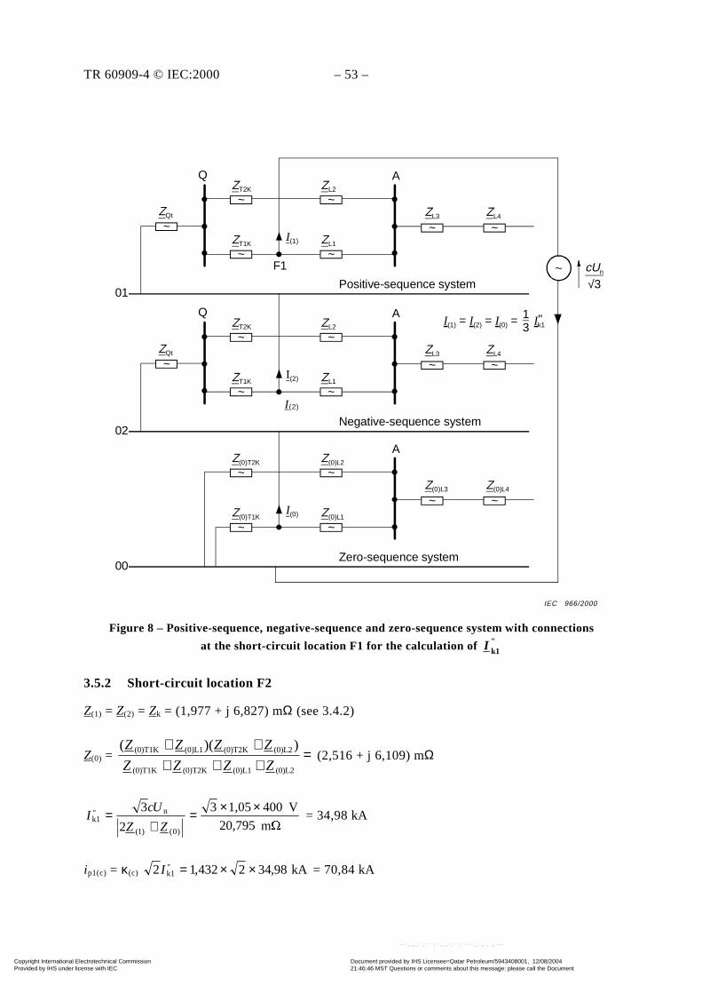
TR 60909-4 © IEC:2000 – 53 –
Figure 8 – Positive-sequence, negative-sequence and zero-sequence system with connections
at the short-circuit location F1 for the calculation of "k1I
3.5.2 Short-circuit location F2
Z(1) = Z(2) = Zk = (1,977 + j 6,827) mΩ (see 3.4.2)
Z(0) = =+++++
(0)L2(0)L1(0)T2K(0)T1K
(0)L2(0)T2K(0)L1(0)T1K ))((
ZZZZ
ZZZZ (2,516 + j 6,109) mΩ
m 20,795
V4001,053
2
3
)0()1(
n"k1
××=+
=ZZ
UcI = 34,98 kA
ip1(c) = κ(c) kA98,342432,12 "k1 ××=I = 70,84 kA
~~
~~
~ ~~ZQt
Q
01Positive-sequence system
ZT2K
ZT1K
F1
ZL2
ZL1I(1)
A
ZL3 ZL4
cUn
√3~
~~
~~
~ ~~ZQt
Q
Negative-sequence system
ZT2K
ZT1K
ZL2
ZL1I(2)
A
ZL3 ZL4
02
~~
~~
~ ~
Zero-sequence system
Z(0)T2K
Z(0)T1K
Z(0)L2
Z(0)L1I(0)
A
Z(0)L3 Z(0)L4
00
I(1) = I(2) = I(0) = Ik1"1
3
I (2)
IEC 966/2000
Copyright International Electrotechnical Commission Provided by IHS under license with IEC
Document provided by IHS Licensee=Qatar Petroleum/5943408001, 12/08/200421:46:46 MST Questions or comments about this message: please call the DocumentPolicy Group at 303-397-2295.
--``,,,,,``,````,``,,,,`,```,``-`-`,,`,,`,`,,`---

– 54 – TR 60909-4 © CEI:2000
3.5.3 Point de court-circuit F3
Z(1) = Z(2) = Zk = (25,897 + j 23,417) mΩ (voir 3.4.3)
Z(0) = Z(0)F2 + Z(0)L3 + Z(0)L4 = (55,816 + j 58,419) mΩ
m 150,550
V4001,053
2
3
)0()1(
n"k1
××=+
=ZZ
UcI = 4,83 kA
ip1(c) = κ(c) kA83,42056,12 "k1 ××=I = 7,21 kA
3.6 Récapitulation des résultats
La récapitulation des résultats pour l'exemple de la figure 6 est donnée au tableau 4a pour lesimpédances de court-circuit et les courants et au tableau 4b pour l'intégrale de Joule (voirl’équation (102) de la CEI 60909-0).
Tableau 4a – Impédances et courants de court-circuit
Point de court-circuit
Zk = Z(1) Z(0)"kI ip(c)
"k1I ip1(c)
"k
"k1 / II
mΩ mΩ kA kA kA kA –
F1 7,003 6,421 34,62 70,85 35,64 72,93 1,03
F2 7,107 6,601 34,12 69,10 34,98 70,84 1,03
F3 34,929 80,79 6,95 10,38 4,83 7,21 0,70
L'intégrale de Joule est calculée aux points de court-circuit F2 et F3 à la figure 6 en utilisant lesfacteurs m et n donnés aux figures 21 et 22 de la CEI 60909-0. Le facteur m est calculé avecl'équation pour m donnée dans l’annexe A de la CEI 60909-0). Les temps de coupure (temps decourt-circuit Tk) pour le fusible sont obtenus à partir d'une caractéristique donnée de fusiblebasse tension 250 A.
Copyright International Electrotechnical Commission Provided by IHS under license with IEC
Document provided by IHS Licensee=Qatar Petroleum/5943408001, 12/08/200421:46:46 MST Questions or comments about this message: please call the DocumentPolicy Group at 303-397-2295.
--``,,,,,``,````,``,,,,`,```,``-`-`,,`,,`,`,,`---
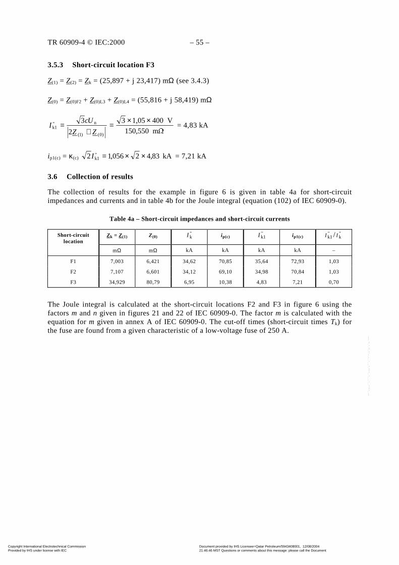
TR 60909-4 © IEC:2000 – 55 –
3.5.3 Short-circuit location F3
Z(1) = Z(2) = Zk = (25,897 + j 23,417) mΩ (see 3.4.3)
Z(0) = Z(0)F2 + Z(0)L3 + Z(0)L4 = (55,816 + j 58,419) mΩ
m 150,550
V4001,053
2
3
)0()1(
n"k1
××=+
=ZZ
UcI = 4,83 kA
ip1(c) = κ(c) kA83,42056,12 "k1 ××=I = 7,21 kA
3.6 Collection of results
The collection of results for the example in figure 6 is given in table 4a for short-circuitimpedances and currents and in table 4b for the Joule integral (equation (102) of IEC 60909-0).
Table 4a – Short-circuit impedances and short-circuit currents
Short-circuitlocation
Zk = Z(1) Z(0)"kI ip(c)
"k1I ip1(c)
"k
"k1 / II
mΩ mΩ kA kA kA kA –
F1 7,003 6,421 34,62 70,85 35,64 72,93 1,03
F2 7,107 6,601 34,12 69,10 34,98 70,84 1,03
F3 34,929 80,79 6,95 10,38 4,83 7,21 0,70
The Joule integral is calculated at the short-circuit locations F2 and F3 in figure 6 using thefactors m and n given in figures 21 and 22 of IEC 60909-0. The factor m is calculated with theequation for m given in annex A of IEC 60909-0. The cut-off times (short-circuit times Tk) forthe fuse are found from a given characteristic of a low-voltage fuse of 250 A.
Copyright International Electrotechnical Commission Provided by IHS under license with IEC
Document provided by IHS Licensee=Qatar Petroleum/5943408001, 12/08/200421:46:46 MST Questions or comments about this message: please call the DocumentPolicy Group at 303-397-2295.
--``,,,,,``,````,``,,,,`,```,``-`-`,,`,,`,`,,`---
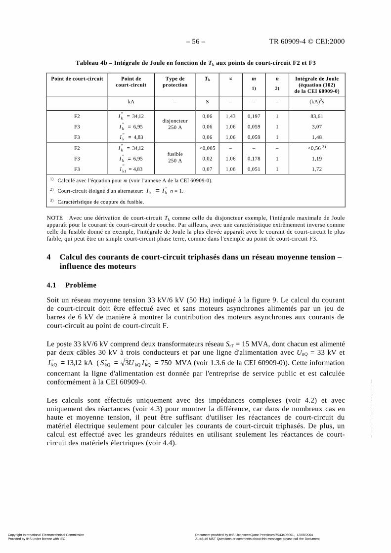
– 56 – TR 60909-4 © CEI:2000
Tableau 4b – Intégrale de Joule en fonction de Tk aux points de court-circuit F2 et F3
Point de court-circuit Point decourt-circuit
Type deprotection
Tk m
1)
n
2)
Intégrale de Joule(équation (102)
de la CEI 60909-0)
kA – S – – – (kA)2s
F2
F3
F3
12,34"k =I
95,6"k =I
83,4"k =I
disjoncteur250 A
0,06
0,06
0,06
1,43
1,06
1,06
0,197
0,059
0,059
1
1
1
83,61
3,07
1,48
F2
F3
F3
12,34"k =I
95,6"k =I
83,4"k1 =I
fusible250 A
<0,005
0,02
0,07
–
1,06
1,06
–
0,178
0,051
–
1
1
<0,56 3)
1,19
1,72
1) Calculé avec l'équation pour m (voir l’annexe A de la CEI 60909-0).
2) Court-circuit éloigné d'un alternateur: "kk II = n = 1.
3) Caractéristique de coupure du fusible.
NOTE Avec une dérivation de court-circuit Tk comme celle du disjoncteur exemple, l'intégrale maximale de Jouleapparaît pour le courant de court-circuit de couche. Par ailleurs, avec une caractéristique extrêmement inverse commecelle du fusible donné en exemple, l'intégrale de Joule la plus élevée apparaît avec le courant de court-circuit le plusfaible, qui peut être un simple court-circuit phase terre, comme dans l'exemple au point de court-circuit F3.
4 Calcul des courants de court-circuit triphasés dans un réseau moyenne tension –influence des moteurs
4.1 Problème
Soit un réseau moyenne tension 33 kV/6 kV (50 Hz) indiqué à la figure 9. Le calcul du courantde court-circuit doit être effectué avec et sans moteurs asynchrones alimentés par un jeu debarres de 6 kV de manière à montrer la contribution des moteurs asynchrones aux courants decourt-circuit au point de court-circuit F.
Le poste 33 kV/6 kV comprend deux transformateurs réseau SrT = 15 MVA, dont chacun est alimentépar deux câbles 30 kV à trois conducteurs et par une ligne d'alimentation avec UnQ = 33 kV et
kA12,13"kQ =I ( MVA7503 "
kQkQ"kQ == IUS (voir 1.3.6 de la CEI 60909-0)). Cette information
concernant la ligne d'alimentation est donnée par l'entreprise de service public et est calculéeconformément à la CEI 60909-0.
Les calculs sont effectués uniquement avec des impédances complexes (voir 4.2) et avecuniquement des réactances (voir 4.3) pour montrer la différence, car dans de nombreux cas enhaute et moyenne tension, il peut être suffisant d'utiliser les réactances de court-circuit dumatériel électrique seulement pour calculer les courants de court-circuit triphasés. De plus, uncalcul est effectué avec les grandeurs réduites en utilisant seulement les réactances de court-circuit des matériels électriques (voir 4.4).
Copyright International Electrotechnical Commission Provided by IHS under license with IEC
Document provided by IHS Licensee=Qatar Petroleum/5943408001, 12/08/200421:46:46 MST Questions or comments about this message: please call the DocumentPolicy Group at 303-397-2295.
--``,,,,,``,````,``,,,,`,```,``-`-`,,`,,`,`,,`---

TR 60909-4 © IEC:2000 – 57 –
Table 4b – Joule integral depending on Tk at the short-circuit location F2 and F3
Short-circuit location Short-circuitlocation
Protectiontype
Tk m
1)
n
2)
Joule integral(equation (102)of IEC 60909-0)
kA – S – – – (kA)2s
F2
F3
F3
12,34"k =I
95,6"k =I
83,4"k =I
circuitbreaker250 A
0,06
0,06
0,06
1,43
1,06
1,06
0,197
0,059
0,059
1
1
1
83,61
3,07
1,48
F2
F3
F3
12,34"k =I
95,6"k =I
83,4"k1 =I
fuse250 A
<0,005
0,02
0,07
–
1,06
1,06
–
0,178
0,051
–
1
1
<0,56 3)
1,19
1,72
1) Calculated with equation for m (see annex A of IEC 60909-0).
2) Far-from-generator short circuit: "kk II = n = 1.
3) Cut-off characteristic of the fuse.
NOTE With a certain short-circuit duration Tk like that of the example circuit-breaker, the maximum Joule integraloccurs for the largest short-circuit current. Whereas with an extremely inverse characteristic like that of the examplefuse, the largest Joule integral occurs with the smallest short-circuit current, which may be a single line-to-earth shortcircuit, as in the example at the short-circuit location F3.
4 Calculation of three-phase short-circuit currents in a medium-voltage system –influence of motors
4.1 Problem
A medium-voltage system 33 kV/6 kV (50 Hz) is given in figure 9. The short-circuit currentcalculation shall be carried out without and with asynchronous motors fed from the 6 kV busbar,to show their contribution to the short-circuit currents at the short-circuit location F.
The substation 33 kV/6 kV with two network transformers SrT = 15 MVA each is fedthrough two three-core 30 kV cables from a network feeder with UnQ = 33 kV and
kA12,13"kQ =I ( MVA7503 "
kQkQ"kQ == IUS (see 1.3.6 of IEC 60909-0)). This information
about the network feeder is given by the public service company, calculated in accordance withIEC 60909-0.
The calculations are carried out with complex impedances (see 4.2) and with reactances only(see 4.3) to show the difference, because in many cases at the high-voltage and the medium-voltage level, it may be sufficient to use the short-circuit reactances of the electrical equipmentonly when calculating three-phase short-circuit currents. In addition, a calculation is performedwith quantities of the per-unit system (see 4.4).
Copyright International Electrotechnical Commission Provided by IHS under license with IEC
Document provided by IHS Licensee=Qatar Petroleum/5943408001, 12/08/200421:46:46 MST Questions or comments about this message: please call the DocumentPolicy Group at 303-397-2295.
--``,,,,,``,````,``,,,,`,```,``-`-`,,`,,`,`,,`---
– 58 – TR 60909-4 © CEI:2000
Un calcul de courant de court-circuit avec la méthode par superposition est présenté en 4.5 pourmontrer que les résultats pour les courants de court-circuit dépendent du flux de puissance, de latension au point de court-circuit avant le court-circuit et de la position des changeurs de prise encharge des transformateurs (voir figure 9).
La figure 9 donne le schéma de circuit du réseau triphasé en courant alternatif 33 kV/6 kV et lescaractéristiques du matériel électrique.
4.2 Calcul complexe à partir de grandeurs réelles
Les impédances complexes de court-circuit du tableau 5 sont calculées avec les données de lafigure 9 et avec les équations données dans la CEI 60909-0.
Le courant de court-circuit "kI au point de court-circuit en F est obtenu à partir d'une addition
complexe des courants de court-circuit partiels à la figure 9 (voir 4.2.1.2 de la CEI 60909-0).
"kM2
"kM1
"kT2
"kT1
"k IIIII +++=
"2kMI est le courant de court-circuit partiel de trois moteurs parallèles avec PrM = 1 MW chacun
(figure 9), traités comme un moteur unique équivalent M2.
Copyright International Electrotechnical Commission Provided by IHS under license with IEC
Document provided by IHS Licensee=Qatar Petroleum/5943408001, 12/08/200421:46:46 MST Questions or comments about this message: please call the DocumentPolicy Group at 303-397-2295.
--``,,,,,``,````,``,,,,`,```,``-`-`,,`,,`,`,,`---
TR 60909-4 © IEC:2000 – 59 –
A short-circuit current calculation with the superposition method is presented in 4.5 to show thatthe results for the short-circuit currents depend on the load flow, the voltage at the short-circuitlocation before the short circuit and the position of on-load tap-changers of transformers (seefigure 9).
Figure 9 gives the circuit diagram of the three-phase a.c. system 33 kV/6 kV and the data ofthe electrical equipment.
4.2 Complex calculation with absolute quantities
The complex short-circuit impedances in table 5 are calculated with the data in figure 9 and withthe equations given in IEC 60909-0.
The short-circuit current "kI at the short-circuit location in F is found from a complex addition of
the partial short-circuit currents in figure 9 (see 4.2.1.2 of IEC 60909-0).
"kM2
"kM1
"kT2
"kT1
"k IIIII +++=
"2kMI is the partial short-circuit current from the three parallel motors with PrM = 1 MW each
(figure 9), dealt with as one equivalent motor M2.
Copyright International Electrotechnical Commission Provided by IHS under license with IEC
Document provided by IHS Licensee=Qatar Petroleum/5943408001, 12/08/200421:46:46 MST Questions or comments about this message: please call the DocumentPolicy Group at 303-397-2295.
--``,,,,,``,````,``,,,,`,```,``-`-`,,`,,`,`,,`---
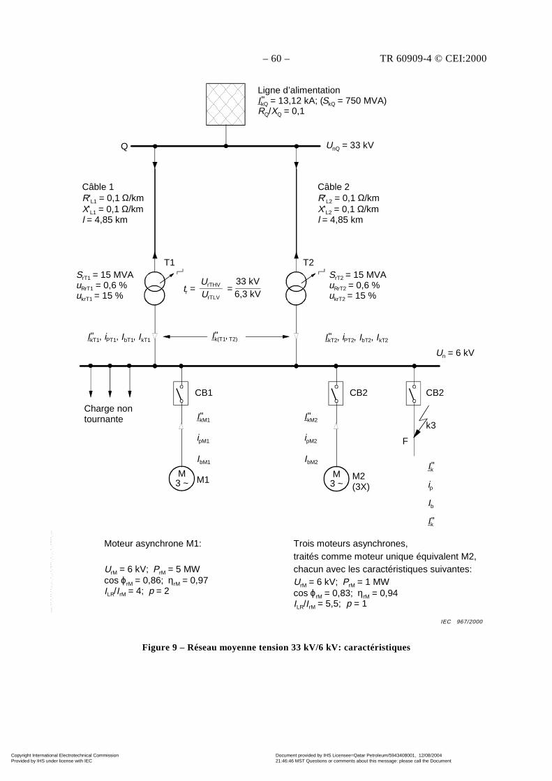
– 60 – TR 60909-4 © CEI:2000
CB1
IkM1
ipM1
IbM1
M1
"
CB2
M2(3X)
IkM2
ipM2
IbM2
"
CB2
k3
F
Ik
ip
Ib
Ik
"
"
Charge nontournante
Un = 6 kV
Ligne d’alimentationIkQ = 13,12 kA; (SkQ = 750 MVA)RQ/XQ = 0,1"
Q
Câble 1R'L1 = 0,1 Ω/kmX'L1 = 0,1 Ω/kml = 4,85 km
SrT1 = 15 MVAuRrT1 = 0,6 %ukrT1 = 15 %
T1
tr =UrTHV
UrTLV=
33 kV6,3 kV
Ik(T1, T2)"IkT1, iPT1, IbT1, IkT1"
Câble 2R'L2 = 0,1 Ω/kmX'L2 = 0,1 Ω/kml = 4,85 km
SrT2 = 15 MVAuRrT2 = 0,6 %ukrT2 = 15 %
IkT2, iPT2, IbT2, IkT2"
T2
UnQ = 33 kV
Moteur asynchrone M1:
UrM = 6 kV; PrM = 5 MWcos ϕrM = 0,86; ηrM = 0,97ILR/IrM = 4; p = 2
Trois moteurs asynchrones,traités comme moteur unique équivalent M2,chacun avec les caractéristiques suivantes:UrM = 6 kV; PrM = 1 MWcos ϕrM = 0,83; ηrM = 0,94ILR/IrM = 5,5; p = 1
M3 ~
M3 ~
Figure 9 – Réseau moyenne tension 33 kV/6 kV: caractéristiques
IEC 967/2000
Copyright International Electrotechnical Commission Provided by IHS under license with IEC
Document provided by IHS Licensee=Qatar Petroleum/5943408001, 12/08/200421:46:46 MST Questions or comments about this message: please call the DocumentPolicy Group at 303-397-2295.
--``,,,,,``,````,``,,,,`,```,``-`-`,,`,,`,`,,`---
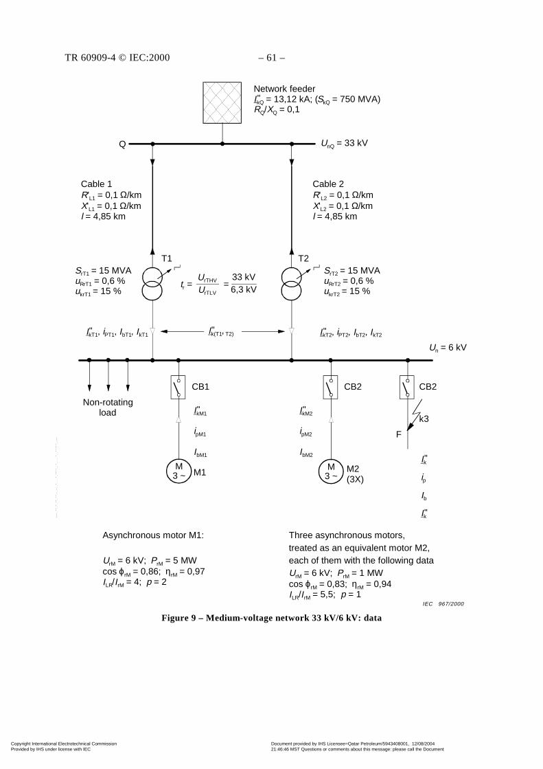
TR 60909-4 © IEC:2000 – 61 –
CB1
IkM1
ipM1
IbM1
M1
"
CB2
M2(3X)
IkM2
ipM2
IbM2
"
CB2
k3
F
Ik
ip
Ib
Ik
"
"
Non-rotatingload
Un = 6 kV
Network feederIkQ = 13,12 kA; (SkQ = 750 MVA)RQ/XQ = 0,1"
Q
Cable 1R'L1 = 0,1 Ω/kmX'L1 = 0,1 Ω/kml = 4,85 km
SrT1 = 15 MVAuRrT1 = 0,6 %ukrT1 = 15 %
T1
tr =UrTHV
UrTLV=
33 kV6,3 kV
Ik(T1, T2)"IkT1, iPT1, IbT1, IkT1"
Cable 2R'L2 = 0,1 Ω/kmX'L2 = 0,1 Ω/kml = 4,85 km
SrT2 = 15 MVAuRrT2 = 0,6 %ukrT2 = 15 %
IkT2, iPT2, IbT2, IkT2"
T2
UnQ = 33 kV
Asynchronous motor M1:
UrM = 6 kV; PrM = 5 MWcos ϕrM = 0,86; ηrM = 0,97ILR/IrM = 4; p = 2
Three asynchronous motors,treated as an equivalent motor M2,each of them with the following dataUrM = 6 kV; PrM = 1 MWcos ϕrM = 0,83; ηrM = 0,94ILR/IrM = 5,5; p = 1
M3 ~
M3 ~
Figure 9 – Medium-voltage network 33 kV/6 kV: data
IEC 967/2000
Copyright International Electrotechnical Commission Provided by IHS under license with IEC
Document provided by IHS Licensee=Qatar Petroleum/5943408001, 12/08/200421:46:46 MST Questions or comments about this message: please call the DocumentPolicy Group at 303-397-2295.
--``,,,,,``,````,``,,,,`,```,``-`-`,,`,,`,`,,`---
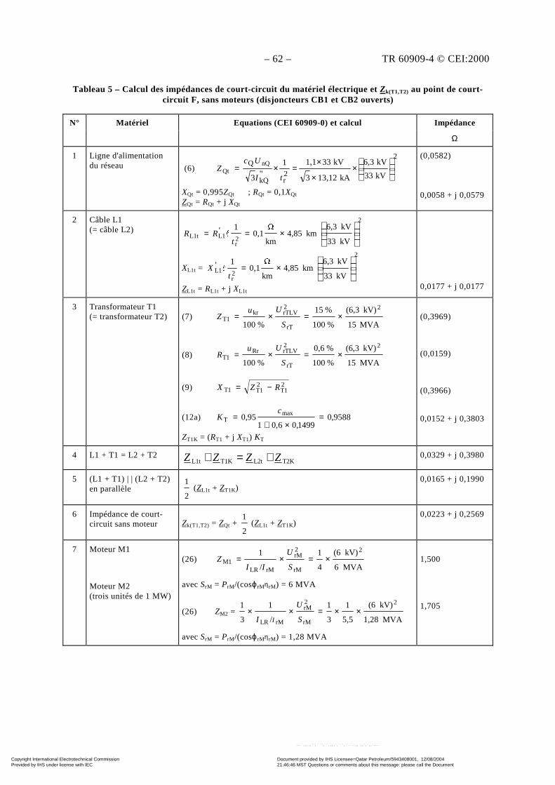
– 62 – TR 60909-4 © CEI:2000
Tableau 5 – Calcul des impédances de court-circuit du matériel électrique et Zk(T1,T2) au point de court-circuit F, sans moteurs (disjoncteurs CB1 et CB2 ouverts)
N° Matériel Equations (CEI 60909-0) et calcul Impédance
Ω
1 Ligne d'alimentationdu réseau (6)
2
2rkQ
Q
kV33
kV6,3
kA13,123
kV331,11"3
nQQt
×
×
×=×=
tI
UcZ
XQt = 0,995ZQt ; RQt = 0,1XQt
ZQt = RQt + j XQt
(0,0582)
0,0058 + j 0,0579
2 Câble L1(= câble L2)
2
2r
L1L1tkV33
kV6,3km4,85
km
0,1
1'
×==
tRR "
XL1t =
2
2r
L1kV33
kV6,3km4,85
km
0,1
1'
×=
tX "
ZL1t = RL1t + j XL1t0,0177 + j 0,0177
3 Transformateur T1(= transformateur T2) (7)
MVA15
kV)(6,3
%100
%15
%100
2
rT
2rTLVkr
1T ×=×=S
UuZ
(8)MVA15
kV)(6,3
%100
%0,6
%100
2
rT
2rTLVRr
1T ×=×=S
UuR
(9) 21T
21T1T RZX −=
(12a) 9588,01499,06,01
95,0 maxT =
×+=
cK
ZT1K = (RT1 + j XT1) KT
(0,3969)
(0,0159)
(0,3966)
0,0152 + j 0,3803
4 L1 + T1 = L2 + T2T2KL2tT1KL1t ZZZZ +=+ 0,0329 + j 0,3980
5 (L1 + T1) | | (L2 + T2)en parallèle
2
1 (ZL1t + ZT1K)
0,0165 + j 0,1990
6 Impédance de court-circuit sans moteur Zk(T1,T2) = ZQt +
2
1 (ZL1t + ZT1K)
0,0223 + j 0,2569
7 Moteur M1
Moteur M2(trois unités de 1 MW)
(26)MVA6
kV)(6
4
1
/
1 2
rM
2rM
rMLR1M ×=×=
S
U
IIZ
avec SrM = PrM/(cosϕrMηrM) = 6 MVA
(26) ZM2 = MVA1,28
kV)(6
5,5
1
3
1
/
1
3
1 2
rM
2rM
rMLR
××=××S
U
I I
avec SrM = PrM/(cosϕrMηrM) = 1,28 MVA
1,500
1,705
Copyright International Electrotechnical Commission Provided by IHS under license with IEC
Document provided by IHS Licensee=Qatar Petroleum/5943408001, 12/08/200421:46:46 MST Questions or comments about this message: please call the DocumentPolicy Group at 303-397-2295.
--``,,,,,``,````,``,,,,`,```,``-`-`,,`,,`,`,,`---
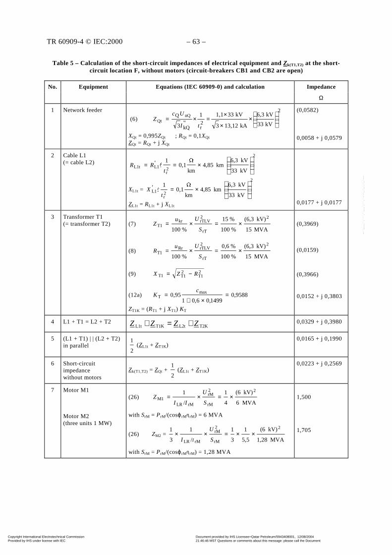
TR 60909-4 © IEC:2000 – 63 –
Table 5 – Calculation of the short-circuit impedances of electrical equipment and Zk(T1,T2) at the short-circuit location F, without motors (circuit-breakers CB1 and CB2 are open)
No. Equipment Equations (IEC 60909-0) and calculation Impedance
Ω
1 Network feeder
(6)
2
2rkQ
Q
kV33
kV6,3
kA13,123
kV331,11"3
nQQt
×
×
×=×=
tI
UcZ
XQt = 0,995ZQt ; RQt = 0,1XQt
ZQt = RQt + j XQt
(0,0582)
0,0058 + j 0,0579
2 Cable L1(= cable L2)
2
2r
L1L1tkV33
kV6,3km4,85
km
0,1
1'
×==
tRR "
XL1t =
2
2r
L1kV33
kV6,3km4,85
km
0,1
1'
×=
tX "
ZL1t = RL1t + j XL1t0,0177 + j 0,0177
3 Transformer T1(= transformer T2) (7)
MVA15
kV)(6,3
%100
%15
%100
2
rT
2rTLVkr
1T ×=×=S
UuZ
(8)MVA15
kV)(6,3
%100
%0,6
%100
2
rT
2rTLVRr
1T ×=×=S
UuR
(9) 21T
21T1T RZX −=
(12a) 9588,01499,06,01
95,0 maxT =
×+=
cK
ZT1K = (RT1 + j XT1) KT
(0,3969)
(0,0159)
(0,3966)
0,0152 + j 0,3803
4 L1 + T1 = L2 + T2T2KL2tT1KL1t ZZZZ +=+ 0,0329 + j 0,3980
5 (L1 + T1) | | (L2 + T2)in parallel
2
1 (ZL1t + ZT1K)
0,0165 + j 0,1990
6 Short-circuitimpedancewithout motors
Zk(T1,T2) = ZQt + 2
1 (ZL1t + ZT1K)
0,0223 + j 0,2569
7 Motor M1
Motor M2(three units 1 MW)
(26)MVA6
kV)(6
4
1
/
1 2
rM
2rM
rMLR1M ×=×=
S
U
IIZ
with SrM = PrM/(cosϕrMηrM) = 6 MVA
(26) ZM2 = MVA1,28
kV)(6
5,5
1
3
1
/
1
3
1 2
rM
2rM
rMLR
××=××S
U
I I
with SrM = PrM/(cosϕrMηrM) = 1,28 MVA
1,500
1,705
Copyright International Electrotechnical Commission Provided by IHS under license with IEC
Document provided by IHS Licensee=Qatar Petroleum/5943408001, 12/08/200421:46:46 MST Questions or comments about this message: please call the DocumentPolicy Group at 303-397-2295.
--``,,,,,``,````,``,,,,`,```,``-`-`,,`,,`,`,,`---
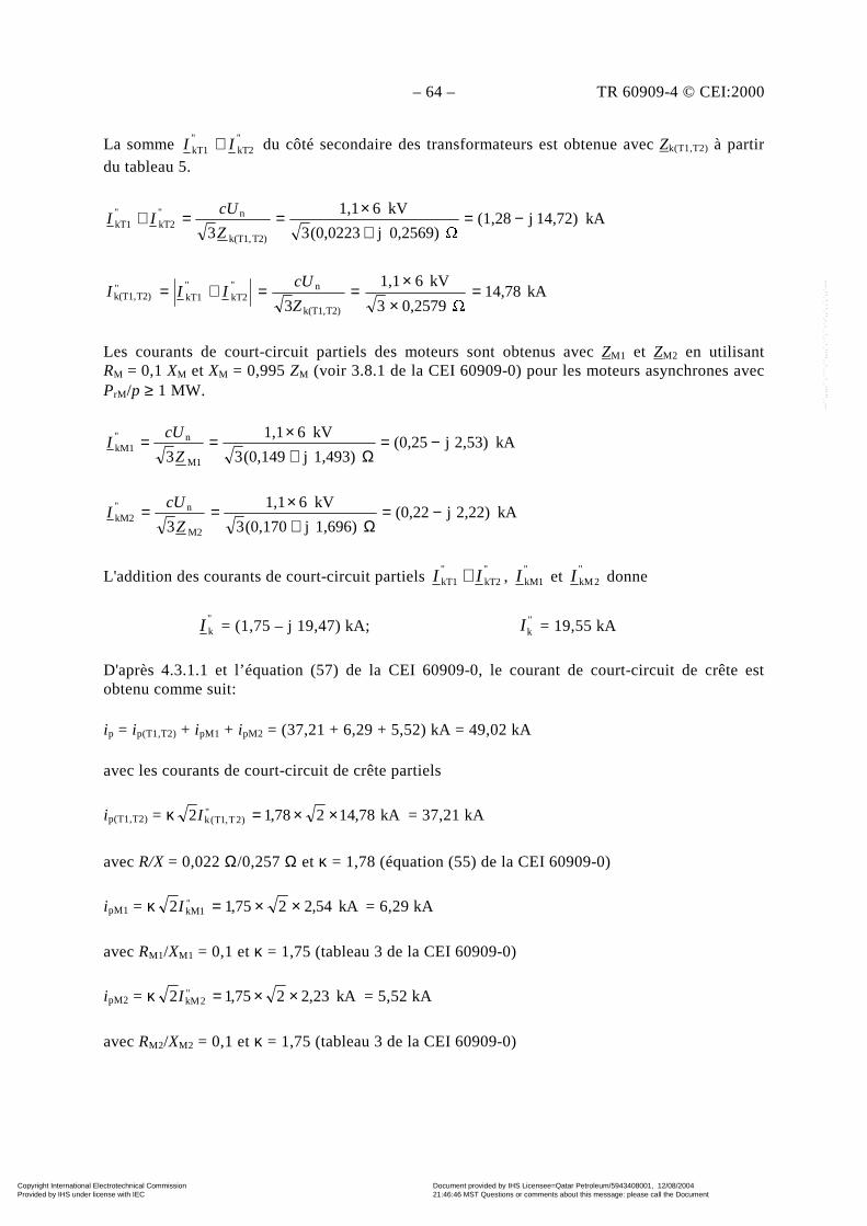
– 64 – TR 60909-4 © CEI:2000
La somme "kT2
"kT1 II + du côté secondaire des transformateurs est obtenue avec Zk(T1,T2) à partir
du tableau 5.
kA14,72)j(1,28 0,2569)j(0,02233
kV61,1
3 T2)k(T1,
n"kT2
"kT1 −=
+×==+
Z
cUII
kA14,78 0,25793
kV61,1
3 T2)k(T1,
n"kT2
"kT1
"T2)k(T1, =
××
==+=Z
cUIII
Les courants de court-circuit partiels des moteurs sont obtenus avec ZM1 et ZM2 en utilisantRM = 0,1 XM et XM = 0,995 ZM (voir 3.8.1 de la CEI 60909-0) pour les moteurs asynchrones avecPrM/p ≥ 1 MW.
kA2,53)j(0,251,493)j(0,1493
kV61,1
3 M1
n"kM1 −=
Ω+×==
Z
cUI
kA2,22)j(0,221,696)j(0,1703
kV61,1
3 M2
n"kM2 −=
Ω+×==
Z
cUI
L'addition des courants de court-circuit partiels "kT2
"kT1 II + ,
"1kMI et
"2kMI donne
"kI = (1,75 – j 19,47) kA; "
kI = 19,55 kA
D'après 4.3.1.1 et l’équation (57) de la CEI 60909-0, le courant de court-circuit de crête estobtenu comme suit:
ip = ip(T1,T2) + ipM1 + ipM2 = (37,21 + 6,29 + 5,52) kA = 49,02 kA
avec les courants de court-circuit de crête partiels
ip(T1,T2) = κ kA78,14278,12 ")2T,1T(k ××=I = 37,21 kA
avec R/X = 0,022 Ω/0,257 Ω et κ = 1,78 (équation (55) de la CEI 60909-0)
ipM1 = κ kA54,2275,12 "1kM ××=I = 6,29 kA
avec RM1/XM1 = 0,1 et κ = 1,75 (tableau 3 de la CEI 60909-0)
ipM2 = κ kA23,2275,12 "2kM ××=I = 5,52 kA
avec RM2/XM2 = 0,1 et κ = 1,75 (tableau 3 de la CEI 60909-0)
Copyright International Electrotechnical Commission Provided by IHS under license with IEC
Document provided by IHS Licensee=Qatar Petroleum/5943408001, 12/08/200421:46:46 MST Questions or comments about this message: please call the DocumentPolicy Group at 303-397-2295.
--``,,,,,``,````,``,,,,`,```,``-`-`,,`,,`,`,,`---
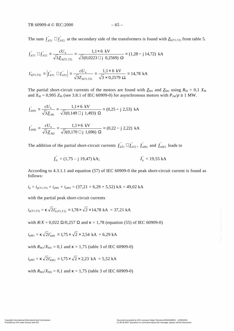
TR 60909-4 © IEC:2000 – 65 –
The sum "kT2
"kT1 II + at the secondary side of the transformers is found with Zk(T1,T2) from table 5.
kA14,72)j(1,28 0,2569)j(0,02233
kV61,1
3 T2)k(T1,
n"kT2
"kT1 −=
+×==+
Z
cUII
kA14,78 0,25793
kV61,1
3 T2)k(T1,
n"kT2
"kT1
"T2)k(T1, =
××
==+=Z
cUIII
The partial short-circuit currents of the motors are found with ZM1 and ZM2 using RM = 0,1 XM
and XM = 0,995 ZM (see 3.8.1 of IEC 60909-0) for asynchronous motors with PrM/p ≥ 1 MW.
kA2,53)j(0,251,493)j(0,1493
kV61,1
3 M1
n"kM1 −=
Ω+×==
Z
cUI
kA2,22)j(0,221,696)j(0,1703
kV61,1
3 M2
n"kM2 −=
Ω+×==
Z
cUI
The addition of the partial short-circuit currents "kT2
"kT1 II + ,
"1kMI and
"2kMI leads to
"kI = (1,75 – j 19,47) kA; "
kI = 19,55 kA
According to 4.3.1.1 and equation (57) of IEC 60909-0 the peak short-circuit current is found asfollows:
ip = ip(T1,T2) + ipM1 + ipM2 = (37,21 + 6,29 + 5,52) kA = 49,02 kA
with the partial peak short-circuit currents
ip(T1,T2) = κ kA78,14278,12 ")2T,1T(k ××=I = 37,21 kA
with R/X = 0,022 Ω/0,257 Ω and κ = 1,78 (equation (55) of IEC 60909-0)
ipM1 = κ kA54,2275,12 "1kM ××=I = 6,29 kA
with RM1/XM1 = 0,1 and κ = 1,75 (table 3 of IEC 60909-0)
ipM2 = κ kA23,2275,12 "2kM ××=I = 5,52 kA
with RM2/XM2 = 0,1 and κ = 1,75 (table 3 of IEC 60909-0)
Copyright International Electrotechnical Commission Provided by IHS under license with IEC
Document provided by IHS Licensee=Qatar Petroleum/5943408001, 12/08/200421:46:46 MST Questions or comments about this message: please call the DocumentPolicy Group at 303-397-2295.
--``,,,,,``,````,``,,,,`,```,``-`-`,,`,,`,`,,`---

– 66 – TR 60909-4 © CEI:2000
D'après 4.5.2 et les équations (70) et (73) de la CEI 60909-0 le courant de court-circuitsymétrique coupé pour un retard temporel minimal tmin = 0,1 s est obtenu comme suit:
Ib = Ib(T1,T2) + IbM1 + IbM2 = "kM2M2M2
"kM1M1M1
"T2)k(T1, qq III ++
Ib = (14,78 + 0,80 × 0,68 × 2,54 + 0,72 × 0,57 × 2,23) kA = 17,08 kA
avec µM1 = 0,62 + 0,72 e-0,32 × 4,4 = 0,80
qM1 = 0,57 + 0,12 × ln 2,5 = 0,68
µM2 = 0,62 + 0,72 e-0,32 × 6,05 = 0,72
qM2 = 0,57 + 0,12 × ln 1,0 = 0,57
La composante apériodique décroissante maximale id.c. du courant de court-circuit à t = tmin = 0,1 speut être estimée avec l'équation (64) de la CEI 60909-0.
id.c. = id.c.(T1,T2) + id.c.M1 + id.c.M2 = (1,420 + 0,155 + 0,137) kA = 1,71 kA
avec id.c.(T1,T2) = )/(ft2")2T,1T(k e2 XRI π− = 1,420 kA
id.c.M1 = )/(22 M1M1e"kM1
XRftI π− = 0,155 kA
id.c.M2 = )/(2 M2M2"kM2e2 XRftI π− = 0,136 kA
Cette composante continue est faible par rapport à Ib.
Comme les moteurs asynchrones ne contribuent pas au courant de court-circuit permanent (IkM1 = 0,IkM2 = 0) dans le cas d'un court-circuit de borne le courant de court-circuit permanent en Fdevient:
Ik = Ik(T1,T2) + IkM1 + IkM2 = kA78,14")2T,1T(k =I
4.3 Calcul avec les réactances de court-circuit du matériel électrique
Le calcul avec les réactances du matériel électrique est suffisant dans le cas où Rk < 0,3 Xk (voir4.2.1.1 de la CEI 60909-0). On peut voir que cette condition est remplie dans ce cas à partir desdonnées indiquées à la figure 9.
Le tableau 6 donne une procédure de calcul approximative pour trouver Xk(T1,T2) sans l'influencedes moteurs asynchrones (CB1 et CB2 sont ouverts).
Copyright International Electrotechnical Commission Provided by IHS under license with IEC
Document provided by IHS Licensee=Qatar Petroleum/5943408001, 12/08/200421:46:46 MST Questions or comments about this message: please call the DocumentPolicy Group at 303-397-2295.
--``,,,,,``,````,``,,,,`,```,``-`-`,,`,,`,`,,`---
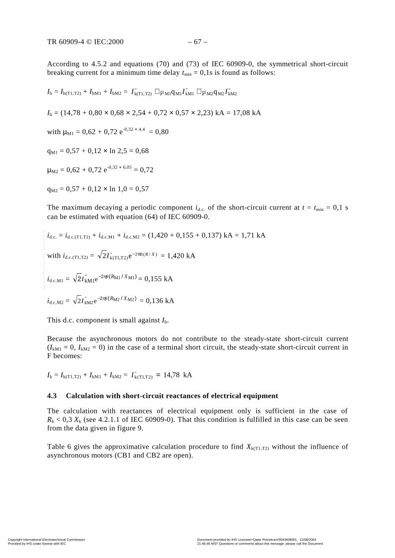
TR 60909-4 © IEC:2000 – 67 –
According to 4.5.2 and equations (70) and (73) of IEC 60909-0, the symmetrical short-circuitbreaking current for a minimum time delay tmin = 0,1s is found as follows:
Ib = Ib(T1,T2) + IbM1 + IbM2 = "kM2M2M2
"kM1M1M1
"T2)k(T1, qq III ++
Ib = (14,78 + 0,80 × 0,68 × 2,54 + 0,72 × 0,57 × 2,23) kA = 17,08 kA
with µM1 = 0,62 + 0,72 e-0,32 × 4,4 = 0,80
qM1 = 0,57 + 0,12 × ln 2,5 = 0,68
µM2 = 0,62 + 0,72 e-0,32 × 6,05 = 0,72
qM2 = 0,57 + 0,12 × ln 1,0 = 0,57
The maximum decaying a periodic component id.c. of the short-circuit current at t = tmin = 0,1 scan be estimated with equation (64) of IEC 60909-0.
id.c. = id.c.(T1,T2) + id.c.M1 + id.c.M2 = (1,420 + 0,155 + 0,137) kA = 1,71 kA
with id.c.(T1,T2) = )/(ft2")2T,1T(k e2 XRI π− = 1,420 kA
id.c.M1 = )/(22 M1M1e"kM1
XRftI π− = 0,155 kA
id.c.M2 = )/(2 M2M2"kM2e2 XRftI π− = 0,136 kA
This d.c. component is small against Ib.
Because the asynchronous motors do not contribute to the steady-state short-circuit current(IkM1 = 0, IkM2 = 0) in the case of a terminal short circuit, the steady-state short-circuit current inF becomes:
Ik = Ik(T1,T2) + IkM1 + IkM2 = kA78,14")2T,1T(k =I
4.3 Calculation with short-circuit reactances of electrical equipment
The calculation with reactances of electrical equipment only is sufficient in the case ofRk < 0,3 Xk (see 4.2.1.1 of IEC 60909-0). That this condition is fulfilled in this case can be seenfrom the data given in figure 9.
Table 6 gives the approximative calculation procedure to find Xk(T1,T2) without the influence ofasynchronous motors (CB1 and CB2 are open).
Copyright International Electrotechnical Commission Provided by IHS under license with IEC
Document provided by IHS Licensee=Qatar Petroleum/5943408001, 12/08/200421:46:46 MST Questions or comments about this message: please call the DocumentPolicy Group at 303-397-2295.
--``,,,,,``,````,``,,,,`,```,``-`-`,,`,,`,`,,`---
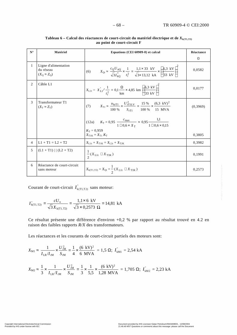
– 68 – TR 60909-4 © CEI:2000
Tableau 6 – Calcul des réactances de court-circuit du matériel électrique et de Xk(T1,T2)
au point de court-circuit F
N° Matériel Equations (CEI 60909-0) et calcul Réactance
Ω
1 Ligne d'alimentationdu réseau(XQ ≈ ZQ)
(6) XQt ≈
2
2rkQ
nQQ
kV33
kV6,3
kA13,123
kV331,11
"3
×
×
×=×
tI
Uc 0,0582
2 Câble L1
XL1t =
2
2r
1LkV33
kV3,6km85,4
km1,0
1'
×
Ω=
tX "
0,0177
3 Transformateur T1(XT ≈ ZT) (7) XT1 ≈
MVA15
kV)(6,3
%100
%15
%100
2
rT1
2rT1LVkrT1 ×=×S
Uu
(12a) KT = 0,95 15,06,01
1,195,0
6,01 T
max
×+≈
×+ X
c
KT = 0,959XT1K = XT1 KT
(0,3969)
0,3805
4 L1 + T1 = L2 + T2 XL1t + XT1K = XL2t + XT2K 0,3982
5 (L1 + T1) | | (L2 + T2))(
2
1K1Tt1L XX + 0,1991
6 Réactance de court-circuitsans moteur Xk(T1,T2) = XQt + )(
2
1K1Tt1L XX + 0,2573
Courant de court-circuit " )2T,1T(kI sans moteur:
kA14,81 0,25733
kV61,1
3 T2)k(T1,
n"T2)k(T1, =
××==
X
cUI
Ce résultat présente une différence d'environ +0,2 % par rapport au résultat trouvé en 4.2 enraison des faibles rapports R/X des transformateurs.
Les réactances et les courants de court-circuit partiels des moteurs sont:
XM1 ≈ MVA6
kV)(6
4
1
/
1 2
rM
2rM
rMLR
×=×S
U
II = 1,5 Ω; "
1kMI = 2,54 kA
XM2 ≈ MVA1,28
kV)(6
5,5
1
3
1
/
1
3
1 2
rM
2rM
rMLR
××=××S
U
II = 1,705 Ω; "
2kMI = 2,23 kA
Copyright International Electrotechnical Commission Provided by IHS under license with IEC
Document provided by IHS Licensee=Qatar Petroleum/5943408001, 12/08/200421:46:46 MST Questions or comments about this message: please call the DocumentPolicy Group at 303-397-2295.
--``,,,,,``,````,``,,,,`,```,``-`-`,,`,,`,`,,`---
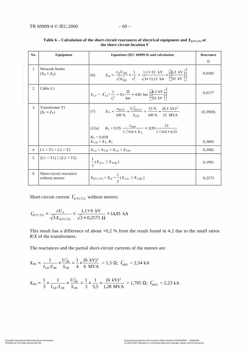
TR 60909-4 © IEC:2000 – 69 –
Table 6 – Calculation of the short-circuit reactances of electrical equipment and Xk(T1,T2) atthe short-circuit location F
No. Equipment Equations (IEC 60909-0) and calculation Reactance
Ω
1 Network feeder(XQ ≈ ZQ) (6) XQt ≈
2
2rkQ
nQQ
kV33
kV6,3
kA13,123
kV331,11
"3
×
×
×=×
tI
Uc 0,0582
2 Cable L1
XL1t =
2
2r
1LkV33
kV3,6km85,4
km1,0
1'
×
Ω=
tX "
0,0177
3 Transformer T1(XT ≈ ZT) (7) XT1 ≈
MVA15
kV)(6,3
%100
%15
%100
2
rT1
2rT1LVkrT1 ×=×S
Uu
(12a) KT = 0,95 15,06,01
1,195,0
6,01 T
max
×+≈
×+ X
c
KT = 0,959XT1K = XT1 KT
(0,3969)
0,3805
4 L1 + T1 = L2 + T2 XL1t + XT1K = XL2t + XT2K 0,3982
5 (L1 + T1) | | (L2 + T2))(
2
1K1Tt1L XX + 0,1991
6 Short-circuit reactancewithout motors Xk(T1,T2) = XQt + )(
2
1K1Tt1L XX + 0,2573
Short-circuit current ")2T,1T(kI without motors:
kA14,81 0,25733
kV61,1
3 T2)k(T1,
n"T2)k(T1, =
××==
X
cUI
This result has a difference of about +0,2 % from the result found in 4.2 due to the small ratiosR/X of the transformers.
The reactances and the partial short-circuit currents of the motors are:
XM1 ≈ MVA6
kV)(6
4
1
/
1 2
rM
2rM
rMLR
×=×S
U
II = 1,5 Ω; "
1kMI = 2,54 kA
XM2 ≈ MVA1,28
kV)(6
5,5
1
3
1
/
1
3
1 2
rM
2rM
rMLR
××=××S
U
II = 1,705 Ω; "
2kMI = 2,23 kA
Copyright International Electrotechnical Commission Provided by IHS under license with IEC
Document provided by IHS Licensee=Qatar Petroleum/5943408001, 12/08/200421:46:46 MST Questions or comments about this message: please call the DocumentPolicy Group at 303-397-2295.
--``,,,,,``,````,``,,,,`,```,``-`-`,,`,,`,`,,`---

– 70 – TR 60909-4 © CEI:2000
Si les moteurs asynchrones contribuent au courant de court-circuit en F (CB1 et CB2 fermés),alors le courant de court-circuit total en F est trouvé comme suit:
"kI = "
)2T,1T(kI + "1kMI + "
2kMI = (14,81 + 2,54 + 2,23) kA = 19,58 kA
Ce résultat est pratiquement le même que celui qui est trouvé en 4.2 ("kI = 19,55 kA).
Le courant de court-circuit de crête est approximativement trouvé pour des R/X concernant lestransformateurs: RT/XT ≈ uRr/ukr = 0,6 %/15 % = 0,04 (du côté conservateur) et RM/XM = 0,1.
ip = ip(T1,T2) + ipM1 + ipM2 = (39,57 + 6,29 + 5,52) kA = 51,38 kA
avec ip(T1,T2) = κ(T1,T2) kA81,14289,12 ")2T,1T(k ××=I = 39,57 kA
ipM1 = κ(M1) kA54,2275,12 "1kM ××=I = 6,29 kA
ipM2 = κ(M2) kA23,2275,12 "2kM ××=I = 5,52 kA
Ce résultat (ip = 51,38 kA) est d'environ 5 % supérieur à celui qui est trouvé en 4.2 avec uncalcul complexe (ip = 49,02 kA).
Le calcul de Ib et Ik est déjà représenté en 4.2.
4.4 Calcul à partir des grandeurs réduites
Comme il est suffisant dans ce cas de prendre uniquement les réactances pour calculer lescourants de court-circuit, comme indiqué en 4.2 et 4.3, ce calcul, utilisant les grandeurs réduitesdoit être effectué avec les réactances du matériel électrique.
Pour le calcul avec des grandeurs réduites, on doit choisir deux valeurs de référence. Cesgrandeurs de référence (indice R) doivent être:
UR = Un = 6 kV ou 33 kV et SR = 100 MVA.
C'est pourquoi les grandeurs réduites (avec astérisques[*] en indice supérieur avant le symbole)sont définies comme suit:
R2R
R
R
R
R*;*;*;*
SS
SU
SZZ
SUI
IUU
U =×=×==
Si le système n'est pas cohérent, cela signifie que UrTHV/UrTLV ≠ UnHV/UnLV, alors le rapport detransformation assignée lié aux tensions réduites devient:
0,9524kV33
kV6
kV6,3
kV33*
kV33R,
kV6R,
rTLV
rTHVr =×=×=
U
U
U
Ut
Copyright International Electrotechnical Commission Provided by IHS under license with IEC
Document provided by IHS Licensee=Qatar Petroleum/5943408001, 12/08/200421:46:46 MST Questions or comments about this message: please call the DocumentPolicy Group at 303-397-2295.
--``,,,,,``,````,``,,,,`,```,``-`-`,,`,,`,`,,`---

TR 60909-4 © IEC:2000 – 71 –
If the asynchronous motors contribute to the short-circuit current in F (CB1 and CB2 closed),then the total short-circuit current in F is found as follows:
"kI = "
)2T,1T(kI + "1kMI + "
2kMI = (14,81 + 2,54 + 2,23) kA = 19,58 kA
This result is nearly the same as that found in 4.2 ("kI = 19,55 kA).
The peak short-circuit current is approximately found with R/X of the transformers: RT/XT ≈uRr/ukr = 0,6 %/ 15 % = 0,04 (on the conservative side) and RM/XM = 0,1.
ip = ip(T1,T2) + ipM1 + ipM2 = (39,57 + 6,29 + 5,52) kA = 51,38 kA
with ip(T1,T2) = κ(T1,T2) kA81,14289,12 ")2T,1T(k ××=I = 39,57 kA
ipM1 = κ(M1) kA54,2275,12 "1kM ××=I = 6,29 kA
ipM2 = κ(M2) kA23,2275,12 "2kM ××=I = 5,52 kA
This result (ip = 51,38 kA) is about 5 % higher than that found in 4.2 with a complex calculation(ip = 49,02 kA).
The calculation of Ib and Ik is already shown in 4.2.
4.4 Calculation with per-unit quantities
Because it is sufficient in this case to take the reactances only, when calculating the short-circuitcurrents, as shown in 4.2 and 4.3, this calculation, using per-unit quantities, shall be carried outwith the reactances of electrical equipment.
For the calculation with per-unit (p.u.) quantities, two reference values have to be chosen. Thesereference quantities (index R) shall be:
UR = Un = 6 kV or 33 kV and SR = 100 MVA.
Per-unit quantities (with asterisks[*] as a superscript before the symbol) therefore are defined asfollows:
R2R
R
R
R
R*;*;*;*
SS
SU
SZZ
SUI
IUU
U =×=×==
If the system is not coherent, that means UrTHV/UrTLV ≠ UnHV/UnLV, then the rated transformationratio related to p.u. voltages becomes:
0,9524kV33
kV6
kV6,3
kV33*
kV33R,
kV6R,
rTLV
rTHVr =×=×=
U
U
U
Ut
Copyright International Electrotechnical Commission Provided by IHS under license with IEC
Document provided by IHS Licensee=Qatar Petroleum/5943408001, 12/08/200421:46:46 MST Questions or comments about this message: please call the DocumentPolicy Group at 303-397-2295.
--``,,,,,``,````,``,,,,`,```,``-`-`,,`,,`,`,,`---
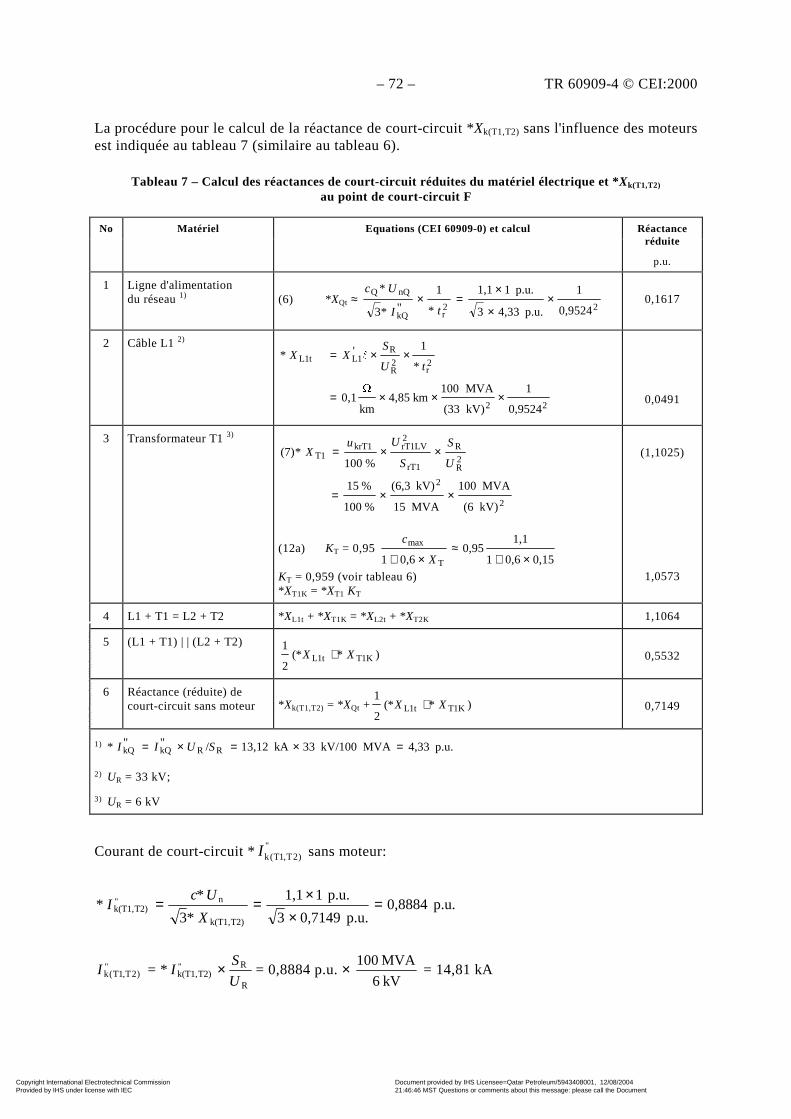
– 72 – TR 60909-4 © CEI:2000
La procédure pour le calcul de la réactance de court-circuit *Xk(T1,T2) sans l'influence des moteursest indiquée au tableau 7 (similaire au tableau 6).
Tableau 7 – Calcul des réactances de court-circuit réduites du matériel électrique et *Xk(T1,T2)
au point de court-circuit F
No Matériel Equations (CEI 60909-0) et calcul Réactanceréduite
p.u.
1 Ligne d'alimentationdu réseau 1) (6) *XQt ≈
22rkQ
nQQ
0,9524
1
p.u.4,333
p.u.11,1
*
1
"*3
*×
×
×=×
tI
Uc0,1617
2 Câble L1 2)
22
2r
2R
RL1L1t
0,9524
1
kV)(33
MVA100km4,85
km
0,1
*
1'*
×××=
××=tU
SXX "
0,0491
3 Transformateur T1 3)
2
2
2R
R
rT1
2rT1LVkrT1
T1
kV)(6
MVA100
MVA15
kV)(6,3
%100
%15
%100*(7)
××=
××=U
S
S
UuX
(12a) KT = 0,95 0,150,61
1,10,95
0,61 T
max
×+≈
×+ X
c
KT = 0,959 (voir tableau 6)*XT1K = *XT1 KT
(1,1025)
1,0573
4 L1 + T1 = L2 + T2 *XL1t + *XT1K = *XL2t + *XT2K 1,1064
5 (L1 + T1) | | (L2 + T2))*(*
2
1K1Tt1L XX + 0,5532
6 Réactance (réduite) decourt-circuit sans moteur *Xk(T1,T2) = *XQt + )*(*
2
1K1Tt1L XX + 0,7149
1) p.u.4,33MVAkV/10033kA13,12/""* RRkQkQ =×=×= SUII
2) UR = 33 kV;
3) UR = 6 kV
Courant de court-circuit *")2T,1T(kI sans moteur:
p.u.0,8884p.u.0,71493
p.u.11,1
*3
**
T2)k(T1,
n"T2)k(T1, =
××
==X
UcI
")2T,1T(kI = *
R
R"T2)k(T1,
U
SI × = 0,8884 p.u. ×
kV6
MVA100 = 14,81 kA
Copyright International Electrotechnical Commission Provided by IHS under license with IEC
Document provided by IHS Licensee=Qatar Petroleum/5943408001, 12/08/200421:46:46 MST Questions or comments about this message: please call the DocumentPolicy Group at 303-397-2295.
--``,,,,,``,````,``,,,,`,```,``-`-`,,`,,`,`,,`---
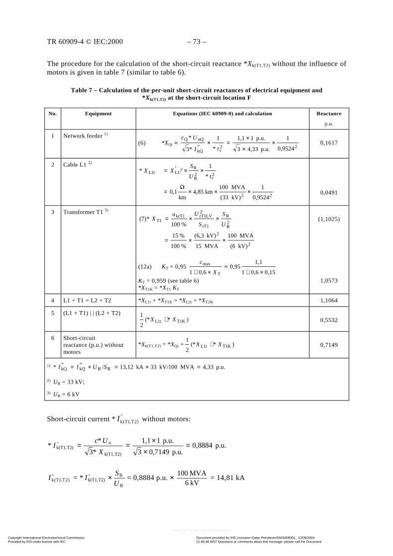
TR 60909-4 © IEC:2000 – 73 –
The procedure for the calculation of the short-circuit reactance *Xk(T1,T2) without the influence ofmotors is given in table 7 (similar to table 6).
Table 7 – Calculation of the per-unit short-circuit reactances of electrical equipment and* Xk(T1,T2) at the short-circuit location F
No. Equipment Equations (IEC 60909-0) and calculation Reactance
p.u.
1 Network feeder 1)
(6) *XQt ≈ 22
rkQ
nQQ
0,9524
1
p.u.4,333
p.u.11,1
*
1
"*3
*×
×
×=×
tI
Uc0,1617
2 Cable L1 2)
22
2r
2R
RL1L1t
0,9524
1
kV)(33
MVA100km4,85
km
0,1
*
1'*
×××=
××=tU
SXX "
0,0491
3 Transformer T1 3)
2
2
2R
R
rT1
2rT1LVkrT1
T1
kV)(6
MVA100
MVA15
kV)(6,3
%100
%15
%100*(7)
××=
××=U
S
S
UuX
(12a) KT = 0,95 0,150,61
1,10,95
0,61 T
max
×+≈
×+ X
c
KT = 0,959 (see table 6)*XT1K = *XT1 KT
(1,1025)
1,0573
4 L1 + T1 = L2 + T2 *XL1t + *XT1K = *XL2t + *XT2K 1,1064
5 (L1 + T1) | | (L2 + T2))*(*
2
1K1Tt1L XX + 0,5532
6 Short-circuitreactance (p.u.) withoutmotors
*Xk(T1,T2) = *XQt + )*(*2
1K1Tt1L XX + 0,7149
1) p.u.4,33MVAkV/10033kA13,12/""* RRkQkQ =×=×= SUII
2) UR = 33 kV;
3) UR = 6 kV
Short-circuit current * ")2T,1T(kI without motors:
p.u.0,8884p.u.0,71493
p.u.11,1
*3
**
T2)k(T1,
n"T2)k(T1, =
××
==X
UcI
")2T,1T(kI = *
R
R"T2)k(T1,
U
SI × = 0,8884 p.u. ×
kV6MVA100
= 14,81 kA
Copyright International Electrotechnical Commission Provided by IHS under license with IEC
Document provided by IHS Licensee=Qatar Petroleum/5943408001, 12/08/200421:46:46 MST Questions or comments about this message: please call the DocumentPolicy Group at 303-397-2295.
--``,,,,,``,````,``,,,,`,```,``-`-`,,`,,`,`,,`---
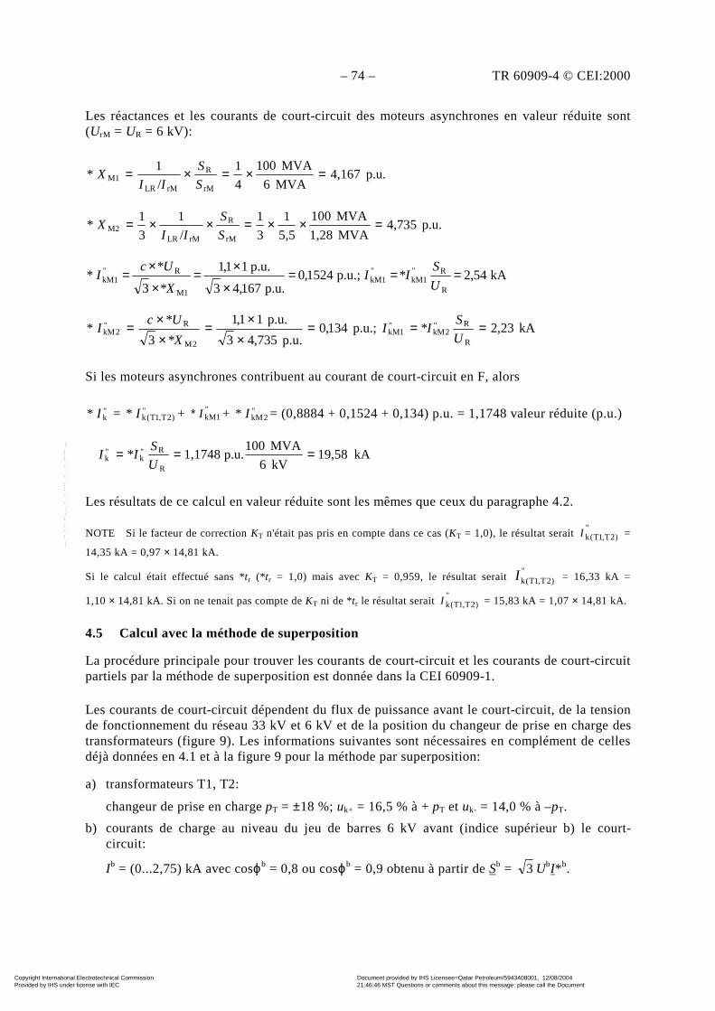
– 74 – TR 60909-4 © CEI:2000
Les réactances et les courants de court-circuit des moteurs asynchrones en valeur réduite sont(UrM = UR = 6 kV):
p.u.4,167MVA6
MVA100
4
1
/
1*
rM
R
rMLRM1 =×=×=
S
S
IIX
p.u.4,735MVA1,28
MVA100
5,5
1
3
1
/
1
3
1*
rM
R
rMLRM2 =××=××=
S
S
IIX
kA54,2p.u.;1524,0p.u.167,43
p.u.11,1
3 R
R1kM1kM
1M
R1kM ===
×
×=
×
×=
U
S*II
*X
*UcI* """
kA23,2p.u.;134,0p.u.735,43
p.u.11,1
3 R
R"2kM
"1kM
2M
R"2kM ===
××
=××=
U
S*II
*X
*UcI*
Si les moteurs asynchrones contribuent au courant de court-circuit en F, alors
"k* I = "
)2T,1T(k* I + "kM1I* + "
2kM* I = (0,8884 + 0,1524 + 0,134) p.u. = 1,1748 valeur réduite (p.u.)
kA19,58kV6
MVA100p.u.1,1748*
R
R"k
"k ===
U
SII
Les résultats de ce calcul en valeur réduite sont les mêmes que ceux du paragraphe 4.2.
NOTE Si le facteur de correction KT n'était pas pris en compte dans ce cas (KT = 1,0), le résultat serait "
)2T,1T(kI =
14,35 kA = 0,97 × 14,81 kA.
Si le calcul était effectué sans *tr (*tr = 1,0) mais avec KT = 0,959, le résultat serait "
)2T,1T(kI = 16,33 kA =
1,10 × 14,81 kA. Si on ne tenait pas compte de KT ni de *tr le résultat serait "
)2T,1T(kI = 15,83 kA = 1,07 × 14,81 kA.
4.5 Calcul avec la méthode de superposition
La procédure principale pour trouver les courants de court-circuit et les courants de court-circuitpartiels par la méthode de superposition est donnée dans la CEI 60909-1.
Les courants de court-circuit dépendent du flux de puissance avant le court-circuit, de la tensionde fonctionnement du réseau 33 kV et 6 kV et de la position du changeur de prise en charge destransformateurs (figure 9). Les informations suivantes sont nécessaires en complément de cellesdéjà données en 4.1 et à la figure 9 pour la méthode par superposition:
a) transformateurs T1, T2:
changeur de prise en charge pT = ±18 %; uk+ = 16,5 % à + pT et uk- = 14,0 % à –pT.
b) courants de charge au niveau du jeu de barres 6 kV avant (indice supérieur b) le court-circuit:
Ib = (0...2,75) kA avec cosϕb = 0,8 ou cosϕb = 0,9 obtenu à partir de Sb = 3 UbI* b.
Copyright International Electrotechnical Commission Provided by IHS under license with IEC
Document provided by IHS Licensee=Qatar Petroleum/5943408001, 12/08/200421:46:46 MST Questions or comments about this message: please call the DocumentPolicy Group at 303-397-2295.
--``,,,,,``,````,``,,,,`,```,``-`-`,,`,,`,`,,`---

TR 60909-4 © IEC:2000 – 75 –
The reactances and the short-circuit currents of the asynchronous motors in p.u. are (UrM = UR
= 6 kV):
p.u.4,167MVA6
MVA100
4
1
/
1*
rM
R
rMLRM1 =×=×=
S
S
IIX
p.u.4,735MVA1,28
MVA100
5,5
1
3
1
/
1
3
1*
rM
R
rMLRM2 =××=××=
S
S
IIX
kA54,2p.u.;1524,0p.u.167,43
p.u.11,1
3 R
R1kM1kM
1M
R1kM ===
×
×=
×
×=
U
S*II
*X
*UcI* """
kA23,2p.u.;134,0p.u.735,43
p.u.11,1
3 R
R"2kM
"1kM
2M
R"2kM ===
××
=××=
U
S*II
*X
*UcI*
If the asynchronous motors contribute to the short-circuit current in F, then
"k* I = "
)2T,1T(k* I + "kM1I* + "
2kM* I = (0,8884 + 0,1524 + 0,134) p.u. = 1,1748 p.u.
kA19,58kV6
MVA100p.u.1,1748*
R
R"k
"k ===
U
SII
The results from this p.u.-calculation are the same as those found in 4.2.
NOTE If in this case the correction factor KT was not taken into account (KT = 1,0), the result was"
)2T,1T(kI =
14,35 kA = 0,97 × 14,81 kA.
If the calculation was carried out without *tr (*tr = 1,0) but with KT = 0,959, the result was "
)2T,1T(kI = 16,33 kA =
1,10 × 14,81 kA. If neither KT nor *tr is taken care of, the result would be "
)2T,1T(kI = 15,83 kA = 1,07 × 14,81 kA.
4.5 Calculation with the superposition method
The principal procedure to find short-circuit currents and partial short-circuit currents with thesuperposition method is given in IEC 60909-1.
The short-circuit currents depend on the load flow before the short circuit, the operating voltageof the 33 kV and 6 kV system and the position of the on-load tap-changer of the transformers(figure 9). The following information in addition to that already given in 4.1 and figure 9 isnecessary for the superposition method:
a) Transformer T1, T2:
On-load tap-changer pT = ±18 %; uk+ = 16,5 % at + pT and uk– = 14,0 % at –pT.
b) Load currents at the 6 kV busbar before (superscript b) the short circuit:
Ib = (0...2,75) kA with cosϕb = 0,8 or cosϕb = 0,9 found from Sb = 3 UbI* b.
Copyright International Electrotechnical Commission Provided by IHS under license with IEC
Document provided by IHS Licensee=Qatar Petroleum/5943408001, 12/08/200421:46:46 MST Questions or comments about this message: please call the DocumentPolicy Group at 303-397-2295.
--``,,,,,``,````,``,,,,`,```,``-`-`,,`,,`,`,,`---
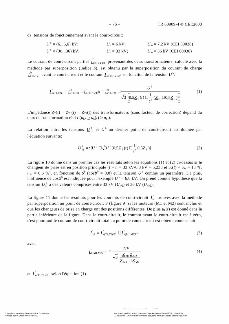
– 76 – TR 60909-4 © CEI:2000
c) tensions de fonctionnement avant le court-circuit:
Ub = (6...6,6) kV; Un = 6 kV; Um = 7,2 kV (CEI 60038)
Ub = (30...36) kV; Un = 33 kV; Um = 36 kV (CEI 60038)
Le courant de court-circuit partiel "
S)2T,1T(kI provenant des deux transformateurs, calculé avec la
méthode par superposition (Indice S), est obtenu par la superposition du courant de chargeb
)2T,1T(I avant le court-circuit et le courant "
U)2T,1T(k bI en fonction de la tension U b:
++
+=+=)0,5(
1)(0,53 LQ2T
bb
T2)(T1,"
T2)Uk(T1,b
T2)(T1,"
T2)Sk(T1, b
ZZt
tZ
UIIII (1)
L'impédance ZT(t) = ZT1(t) = ZT2(t) des transformateurs (sans facteur de correction) dépend dutaux de transformation réel t (uk+ > uk(t) ≥ uk-).
La relation entre les tensions bQU et U b au dernier point de court-circuit est donnée par
l'équation suivante:
)]0,51
)((0,53[ L2Tbbb
Q Zt
tZIUtU ++= (2)
La figure 10 donne dans un premier cas les résultats selon les équations (1) et (2) ci-dessus si lechangeur de prise est en position principale (t = tr = 33 kV/6,3 kV = 5,238 et uk(t) = ukr = 15 %;uRr = 0,6 %), en fonction de Sb (cosϕb = 0,8) et la tension U b comme un paramètre. De plus,l'influence de cosϕb est indiquée pour l'exemple U b = 6,0 kV. On prend comme hypothèse que la
tension bQU a des valeurs comprises entre 33 kV (UnQ) et 36 kV (UmQ).
La figure 11 donne les résultats pour les courants de court-circuit "kSI trouvés avec la méthode
par superposition au point de court-circuit F (figure 9) si les moteurs (M1 et M2) sont inclus etque les changeurs de prise en charge ont des positions différentes. De plus uk(t) est donné dans lapartie inférieure de la figure. Dans le court-circuit, le courant avant le court-circuit est à zéro,c'est pourquoi le courant de court-circuit total au point de court-circuit est obtenu comme suit:
"M2)Uk(M1,
"T2)Uk(T1,
"kS bb III += (3)
avec
M2M1
M2M1
b"
bM2)Uk(M1,
3ZZ
ZZU
I
+
= (4)
et "
U)2T,1T(k bI selon l'équation (1).
Copyright International Electrotechnical Commission Provided by IHS under license with IEC
Document provided by IHS Licensee=Qatar Petroleum/5943408001, 12/08/200421:46:46 MST Questions or comments about this message: please call the DocumentPolicy Group at 303-397-2295.
--``,,,,,``,````,``,,,,`,```,``-`-`,,`,,`,`,,`---

TR 60909-4 © IEC:2000 – 77 –
c) Operating voltages before the short circuit:
Ub = (6...6,6) kV; Un = 6 kV; Um = 7,2 kV (IEC 60038)
Ub = (30...36) kV; Un = 33 kV; Um = 36 kV (IEC 60038)
The partial short-circuit current "
S)2T,1T(kI fed from both the transformers calculated with the
superposition method (Index S) is found from the superposition of the load current b
)2T,1T(I
before the short circuit and the current "
U)2T,1T(k bI depending on the voltage U b:
++
+=+=)0,5(
1)(0,53 LQ2T
bb
T2)(T1,"
T2)Uk(T1,b
T2)(T1,"
T2)Sk(T1, b
ZZt
tZ
UIIII (1)
The impedance ZT(t) = ZT1(t) = ZT2(t) of the transformers (without correction factor) depends onthe actual transformation ratio t (uk+ > uk(t) ≥ uk-).
The relation between the voltages bQU and U b at the later short-circuit location is given by the
following equation:
)]0,51
)((0,53[ L2Tbbb
Q Zt
tZIUtU ++= (2)
Figure 10 gives in a first case the results according to equations (1) and (2) if the tap-changer isin the main position (t = tr = 33 kV/6,3 kV = 5,238 and uk(t) = ukr = 15 %; uRr = 0,6 %),depending on Sb (cosϕb = 0,8) and the voltage U b as a parameter. In addition, the influence of
cosϕb is indicated for the example U b = 6,0 kV. It is anticipated that the voltage bQU has values
between 33 kV (UnQ) and 36 kV (UmQ).
Figure 11 gives the results for the short-circuit currents "kSI found with the superposition method
at the short-circuit location F (figure 9) if the motors (M1 and M2) are included and the on-loadtap-changers have different positions. In addition, uk(t) is given in the lower part of the figure. Inthe short circuit, the current before the short circuit is zero, therefore the total short-circuitcurrent at the short-circuit location is found as follows:
"M2)Uk(M1,
"T2)Uk(T1,
"kS bb III += (3)
with
M2M1
M2M1
b"
bM2)Uk(M1,
3ZZ
ZZU
I
+
= (4)
and "
U)2T,1T(k bI according to equation (1).
Copyright International Electrotechnical Commission Provided by IHS under license with IEC
Document provided by IHS Licensee=Qatar Petroleum/5943408001, 12/08/200421:46:46 MST Questions or comments about this message: please call the DocumentPolicy Group at 303-397-2295.
--``,,,,,``,````,``,,,,`,```,``-`-`,,`,,`,`,,`---
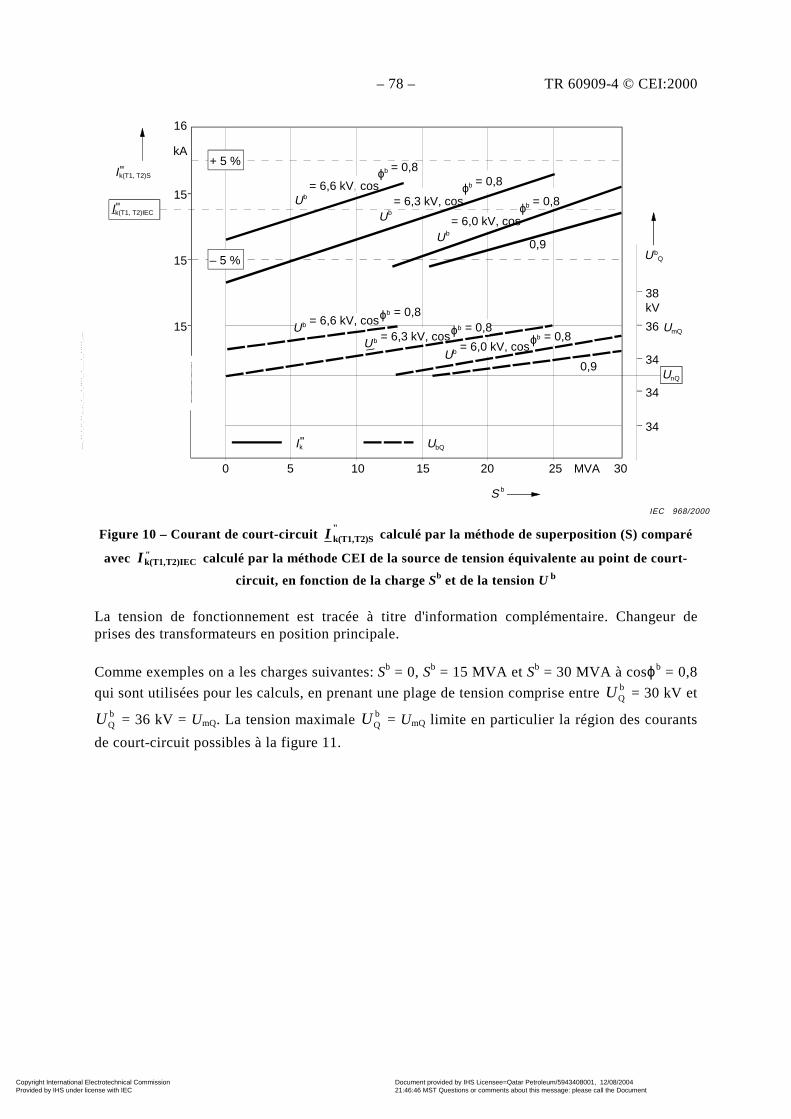
– 78 – TR 60909-4 © CEI:2000
16
kA
15
15
15
Ik(T1, T2)IEC"
Ik(T1, T2)S"
0 5 10 15 20 25 MVA 30
S b
UbQIk"
+ 5 %
– 5 %
Ub = 6,6 kV, cos
ϕb = 0,8
0,9Ub
= 6,0 kV, cosϕb = 0,8
Ub = 6,3 kV, cos
ϕb = 0,8
0,9Ub = 6,0 kV, cosϕb = 0,8Ub = 6,3 kV, cosϕb = 0,8Ub = 6,6 kV, cosϕb = 0,8
38
36
34
UbQ
UmQ
kV
UnQ
34
34
Figure 10 – Courant de court-circuit "
T2)Sk(T1,I calculé par la méthode de superposition (S) comparé
avec "T2)IECk(T1,I calculé par la méthode CEI de la source de tension équivalente au point de court-
circuit, en fonction de la charge Sb et de la tension U b
La tension de fonctionnement est tracée à titre d'information complémentaire. Changeur deprises des transformateurs en position principale.
Comme exemples on a les charges suivantes: Sb = 0, Sb = 15 MVA et Sb = 30 MVA à cosϕb = 0,8
qui sont utilisées pour les calculs, en prenant une plage de tension comprise entre bQU = 30 kV et
bQU = 36 kV = UmQ. La tension maximale b
QU = UmQ limite en particulier la région des courants
de court-circuit possibles à la figure 11.
IEC 968/2000
Copyright International Electrotechnical Commission Provided by IHS under license with IEC
Document provided by IHS Licensee=Qatar Petroleum/5943408001, 12/08/200421:46:46 MST Questions or comments about this message: please call the DocumentPolicy Group at 303-397-2295.
--``,,,,,``,````,``,,,,`,```,``-`-`,,`,,`,`,,`---

TR 60909-4 © IEC:2000 – 79 –
16
kA
15
15
15
Ik(T1, T2)IEC"
Ik(T1, T2)S"
0 5 10 15 20 25 MVA 30
Sb
UbQIk"
+ 5 %
– 5 %
Ub = 6,6 kV, cos
ϕb = 0,8
0,9U b
= 6,0 kV, cosϕb = 0,8
Ub
= 6,3 kV, cosϕb = 0,8
0,9Ub = 6,0 kV, cosϕb = 0,8Ub = 6,3 kV, cosϕb = 0,8Ub = 6,6 kV, cosϕb = 0,8
38
36
34
UbQ
UmQ
kV
UnQ
34
34
Figure 10 – Short-circuit current "
T2)Sk(T1,I calculated by the superposition method (S) compared
with "T2)IECk(T1,I calculated by the IEC method of equivalent voltage source at the short-circuit
location, depending on the load Sb and the voltage U b
As an additional information, the operating voltage is plotted. Tap-changer of the transformers inmain position.
As examples the following loads: Sb = 0, Sb = 15 MVA and Sb = 30 MVA at cosϕb = 0,8 are used
for calculations, considering a voltage range between bQU = 30 kV and b
QU = 36 kV = UmQ.
Especially the maximum voltage bQU = UmQ is limiting the region of possible short-circuit
currents in figure 11.
IEC 968/2000
Copyright International Electrotechnical Commission Provided by IHS under license with IEC
Document provided by IHS Licensee=Qatar Petroleum/5943408001, 12/08/200421:46:46 MST Questions or comments about this message: please call the DocumentPolicy Group at 303-397-2295.
--``,,,,,``,````,``,,,,`,```,``-`-`,,`,,`,`,,`---
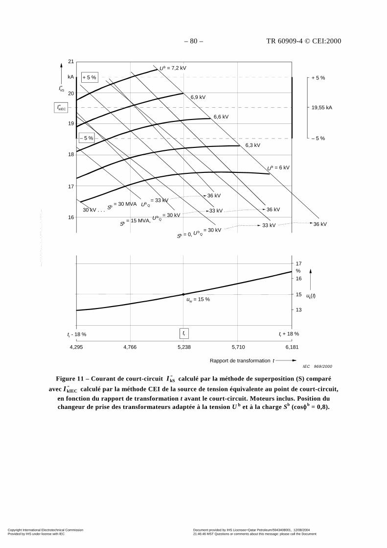
– 80 – TR 60909-4 © CEI:2000
21
kA
20
19
18
17
16
tr - 18 % tr tr + 18 %
uk(t)ukr = 15 %
6,1815,7105,238
Rapport de transformation t
4,7664,295
13
15
16
%17
– 5 %
19,55 kA
+ 5 %
6,3 kV
U b = 6 kV
36 kV
36 kV
33 kV
33 kV 36 kV
UbQ = 33 kV
Sb = 15 MVA, U bQ = 30 kV
Sb = 0, U bQ = 30 kV
30 kV . . . Sb = 30 MVA
6,6 kV
6,9 kV
U b = 7,2 kV
IkS"
IkIEC"
+ 5 %
– 5 %
Figure 11 – Courant de court-circuit "kSI calculé par la méthode de superposition (S) comparé
avec "kIECI calculé par la méthode CEI de la source de tension équivalente au point de court-circuit,
en fonction du rapport de transformation t avant le court-circuit. Moteurs inclus. Position duchangeur de prise des transformateurs adaptée à la tension U b et à la charge Sb (cosϕb = 0,8).
IEC 969/2000
Copyright International Electrotechnical Commission Provided by IHS under license with IEC
Document provided by IHS Licensee=Qatar Petroleum/5943408001, 12/08/200421:46:46 MST Questions or comments about this message: please call the DocumentPolicy Group at 303-397-2295.
--``,,,,,``,````,``,,,,`,```,``-`-`,,`,,`,`,,`---
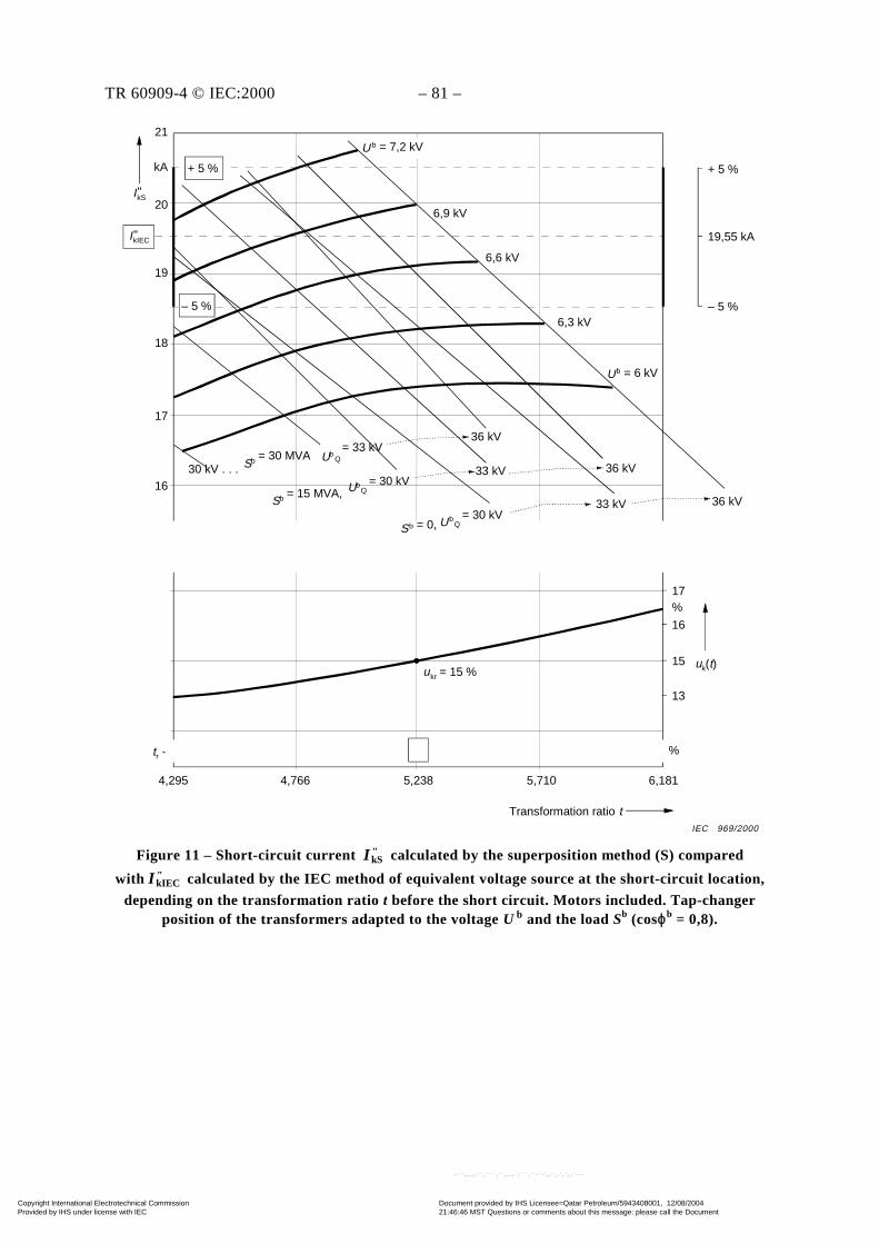
TR 60909-4 © IEC:2000 – 81 –
21
kA
20
19
18
17
16
tr - 18 % tr tr + 18 %
uk(t)ukr = 15 %
6,1815,7105,238
Transformation ratio t
4,7664,295
13
15
16
%17
– 5 %
19,55 kA
+ 5 %
6,3 kV
Ub = 6 kV
36 kV
36 kV
33 kV
33 kV 36 kV
UbQ = 33 kV
Sb = 15 MVA, UbQ = 30 kV
Sb = 0, UbQ = 30 kV
30 kV . . . Sb = 30 MVA
6,6 kV
6,9 kV
U b = 7,2 kV
IkS"
IkIEC"
+ 5 %
– 5 %
Figure 11 – Short-circuit current "kSI calculated by the superposition method (S) compared
with "kIECI calculated by the IEC method of equivalent voltage source at the short-circuit location,
depending on the transformation ratio t before the short circuit. Motors included. Tap-changerposition of the transformers adapted to the voltage U b and the load Sb (cosϕb = 0,8).
IEC 969/2000
Copyright International Electrotechnical Commission Provided by IHS under license with IEC
Document provided by IHS Licensee=Qatar Petroleum/5943408001, 12/08/200421:46:46 MST Questions or comments about this message: please call the DocumentPolicy Group at 303-397-2295.
--``,,,,,``,````,``,,,,`,```,``-`-`,,`,,`,`,,`---
– 82 – TR 60909-4 © CEI:2000
5 Calcul des courants de court-circuit triphasés pour un groupe de production etle réseau auxiliaire
5.1 Problème
Les courants de court-circuit triphasés aux points de court-circuit F1 à F5 de la figure 12 doiventêtre calculés selon la CEI 60909-0.
Un groupe de production (S) où SrG = SrT = 250 MVA est relié à une ligne d'alimentation
du réseau dont UnQ = 220 kV. Le courant de court-circuit réel est donné pour "kQI = 21 kA
par l'entreprise de service public, calculé conformément à la CEI 60909-0, c = cmax = 1,1( )MVA00083 "
kQ"nQ
"kQ ≈≈ IUS . Le transformateur est équipé d'un changeur de prise en
charge du côté haute tension (voir 3.7.1 de la CEI 60909-0). Le transformateur auxiliaire AT estun transformateur à trois enroulements (voir 3.3.2 de la CEI 60909-0) avec deux enroulementssecondaires alimentant les deux jeux de barres séparés auxiliaires B et C avec UnB = UnC = 10 kV.
Il faut tenir compte de l'influence des moteurs asynchrones moyenne et basse tension lors ducalcul des courants de court-circuit de F2 à F5 (voir 3.8 de la CEI 60909-0). Les groupesmoteurs basse tension reliés aux jeux de barres D et E sont traités comme des moteurséquivalents (voir 3.8.2 de la CEI 60909-0).
Les courants de court-circuit aux bornes des moteurs moyenne tension M1 à M14 et des groupesde moteurs basse tension M15 à M26 sont calculés aux tableaux 8 et 9 en utilisant (tableau 3 dela CEI 60909-0). On ne tient pas compte des impédances des câbles de liaison entre les jeux debarres et les moteurs. C'est pourquoi les résultats seront plutôt conservateurs.
On prévoit que tous les moteurs asynchrones fonctionnent avec des charges différentes. Cecidonnera aussi des résultats plutôt conservateurs. La somme de la puissance assignée apparentedes moteurs asynchrones au niveau des jeux de barres B s'élève à ΣSrMB ≈ 40 MVA et au niveaudu jeu de barres C approximativement à ΣSrMC ≈ 30 MVA. Contrairement à ces puissancesassignées apparentes, la charge auxiliaire maximale en fonctionnement du groupe de productions'élèvera environ à 25 MVA ≤ SrATA = 0,1 × SrG dans un groupe de production fonctionnant aucharbon.
Au paragraphe 5.3.4, qui traite du court-circuit en F4, on peut montrer que les moteurs alimentésseulement par les jeux de barres C contribuent pour moins de 1 % au courant de court-circuit
initial "
4kFI . Ainsi les résultats pour les courants de court-circuit en F4 sont pratiquement lesmêmes si les moteurs M8...M14 et les groupes de moteurs M21...M26 fonctionnent.
Copyright International Electrotechnical Commission Provided by IHS under license with IEC
Document provided by IHS Licensee=Qatar Petroleum/5943408001, 12/08/200421:46:46 MST Questions or comments about this message: please call the DocumentPolicy Group at 303-397-2295.
--``,,,,,``,````,``,,,,`,```,``-`-`,,`,,`,`,,`---
TR 60909-4 © IEC:2000 – 83 –
5 Calculation of three-phase short-circuit currents for a power station unit and theauxiliary network
5.1 Problem
Three-phase short-circuit currents at the short-circuit locations F1 to F5 in figure 12 shall becalculated according to IEC 60909-0.
A power-station unit (S) with SrG = SrT = 250 MVA is connected to a network feeder with
UnQ = 220 kV. The actual short-circuit current is given as "kQI = 21 kA by the public service company,
calculated in accordance with IEC 60909-0, c = cmax = 1,1 ( )MVA00083 "kQ
"nQ
"kQ ≈≈ IUS . The
unit transformer is equipped with an on-load tap-changer at the high-voltage side (see 3.7.1 ofIEC 60909-0). The auxiliary transformer AT is a three-winding transformer (see 3.3.2 ofIEC 60909-0) with two secondary windings feeding the two separate auxiliary busbars B and Cwith UnB = UnC = 10 kV.
The influence of the medium- and low-voltage asynchronous motors must be taken into accountwhen calculating short-circuit currents in F2 to F5 (see 3.8 of IEC 60909-0). The low-voltagemotor groups, connected to the busbars D and E, are treated as equivalent motors (see 3.8.2 ofIEC 60909-0).
The terminal short-circuit currents of the medium-voltage motors M1 to M14 and the low-voltage motor groups M15 to M26 are calculated in table 8 and table 9 using table 3 ofIEC 60909-0. The impedances of the connecting cables between the busbars and the motors areneglected. The results therefore will be on the conservative side.
It is anticipated that all the asynchronous motors are in operation at different loads. Thiswill also lead to results on the conservative side. The sum of the rated apparent power ofthe asynchronous motors at busbar B reaches ΣSrMB ≈ 40 MVA and at busbar C approximatelyΣSrMC ≈ 30 MVA. Contrary to these rated apparent powers, the maximum auxiliary load duringoperation of the power station unit will reach approximately 25 MVA ≤ SrATA= 0,1 × SrG in acoal-fired power station.
In 5.3.4 dealing with the short circuit in F4, it can be shown that the motors fed from busbar C
only contribute less than 1 % to the initial short-circuit current "
4kFI . So the results for the short-circuit currents in F4 are nearly the same, if the motors M8...M14 and the motor groupsM21...M26 are not in operation.
Copyright International Electrotechnical Commission Provided by IHS under license with IEC
Document provided by IHS Licensee=Qatar Petroleum/5943408001, 12/08/200421:46:46 MST Questions or comments about this message: please call the DocumentPolicy Group at 303-397-2295.
--``,,,,,``,````,``,,,,`,```,``-`-`,,`,,`,`,,`---
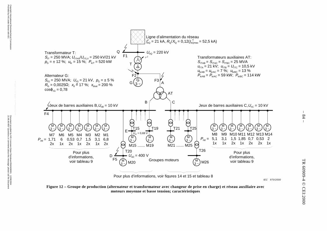
– 82 – TR 60909-4 © CEI:2000
G3 ~
M3 ~
M3 ~
M3 ~
M3 ~
M3 ~
M3 ~
M3 ~
M3 ~
M3 ~
M3 ~
M3 ~
M3 ~
M3 ~
M3 ~
M3 ~
M3 ~
M3 ~
M3 ~
M3 ~
M3 ~
Ligne d’alimentation du réseauIkQ = 21 kA, RQ/XQ = 0,12(IkQmax = 52,5 kA)" "
UnQ = 220 kV
F2F3
AG
B C
AT
Transformateurs auxiliaires AT:SrTAB = SrTAC = SrTBC = 25 MVAurTA = 21 kV; urTB = UrTC = 10,5 kVukrAB = ukrAC = 7 %; ukrBC = 13 %PkrAB = PkrAC = 59 kW; PkrBC = 114 kW
Transformateur T:SrT = 250 MVA; UrTHV/UrTLV = 250 kV/21 kVpG = ± 12 %; ukr = 15 %; PkrT = 520 kW
Alternateur G:SrG = 250 MVA; UrG = 21 kV, pG = ± 5 %RG = 0,0025Ω; xd = 17 %; xdsat = 200 %cosϕrG = 0,78
F4
Jeux de barres auxiliaires B,UnB = 10 kV Jeux de barres auxiliaires C,UnC = 10 kV
M71,712x
PrM =M661x
M50,532x
M40,71x
M31,52x
M23,11x
M16,82x
DF5
M20
T20UnD = 400 V
M15 ....... M19
UnE = 0,69 VE
T15 T19 T21 T25
T26
M85,11x
PrM =M93,11x
M101,52x
M111,851x
M120,72x
M130,532x
M1421x
Pour plusd’informations,voir tableau 9
Pour plus d’informations, voir figures 14 et 15 et tableau 8
M26Groupes moteurs
F1Q
T
"
M21 ....... M25
Pour plusd’informations,voir tableau 9
Figure 12 – Groupe de production (alternateur et transformateur avec changeur de prise en charge) et réseau auxiliaire avecmoteurs moyenne et basse tension; caractéristiques
IEC 970/2000
– 8
4 –
TR
60
90
9-4
© C
EI:2
00
0
Copyright International E
lectrotechnical Com
mission
Provided by IH
S under license w
ith IEC
Docum
ent provided by IHS
Licensee=Q
atar Petroleum
/5943408001, 12/08/200421:46:46 M
ST
Questions or com
ments about this m
essage: please call the Docum
entP
olicy Group at 303-397-2295.
--``,,,,,``,````,``,,,,`,```,``-`-`,,`,,`,`,,`---
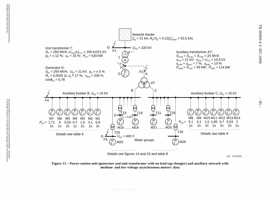
TR 60909-4 © IEC:2000 – 83 –
G3 ~
M3 ~
M3 ~
M3 ~
M3 ~
M3 ~
M3 ~
M3 ~
M3 ~
M3 ~
M3 ~
M3 ~
M3 ~
M3 ~
M3 ~
M3 ~
M3 ~
M3 ~
M3 ~
M3 ~
M3 ~
Network feederIkQ = 21 kA, RQ/XQ = 0,12(IkQmax = 52,5 kA)" "
UnQ = 220 kV
F2F3
AG
B C
AT
Auxiliary transformer AT:SrTAB = SrTAC = SrTBC = 25 MVAurTA = 21 kV; urTB = UrTC = 10,5 kVukrAB = ukrAC = 7 %; ukrBC = 13 %PkrAB = PkrAC = 59 kW; PkrBC = 114 kW
Unit transformer T:SrT = 250 MVA; UrTHV/UrTLV = 250 kV/21 kVpG = ± 12 %; ukr = 15 %; PkrT = 520 kW
Generator G:SrG = 250 MVA; UrG = 21 kV, pG = ± 5 %RG = 0,0025 Ω; xd = 17 %; xdsat = 200 %cosϕrG = 0,78
F4
Auxiliary busbar B, UnB = 10 kV Auxiliary busbar C, UnC = 10 kV
M71,712x
PrM =M661x
M50,532x
M40,71x
M31,52x
M23,11x
M16,82x
Details see table 9D
F5M20
T20UnD = 400 V
M15 ....... M19
UnE = 0,69 VE
T15 T19 T21 T25
T26
M85,11x
PrM =M93,11x
M101,52x
M111,851x
M120,72x
M130,532x
M1421x
Details see table 9
Details see figures 14 and 15 and table 8
M26Motor groups
F1Q
T
"
M21 ....... M25
Figure 12 – Power-station unit (generator and unit transformer with on-load tap-changer) and auxiliary network withmedium- and low-voltage asynchronous motors: data
IEC 970/2000
TR
60
90
9-4
© IE
C:2
00
0 –
85
–
Copyright International E
lectrotechnical Com
mission
Provided by IH
S under license w
ith IEC
Docum
ent provided by IHS
Licensee=Q
atar Petroleum
/5943408001, 12/08/200421:46:46 M
ST
Questions or com
ments about this m
essage: please call the Docum
entP
olicy Group at 303-397-2295.
--``,,,,,``,````,``,,,,`,```,``-`-`,,`,,`,`,,`---
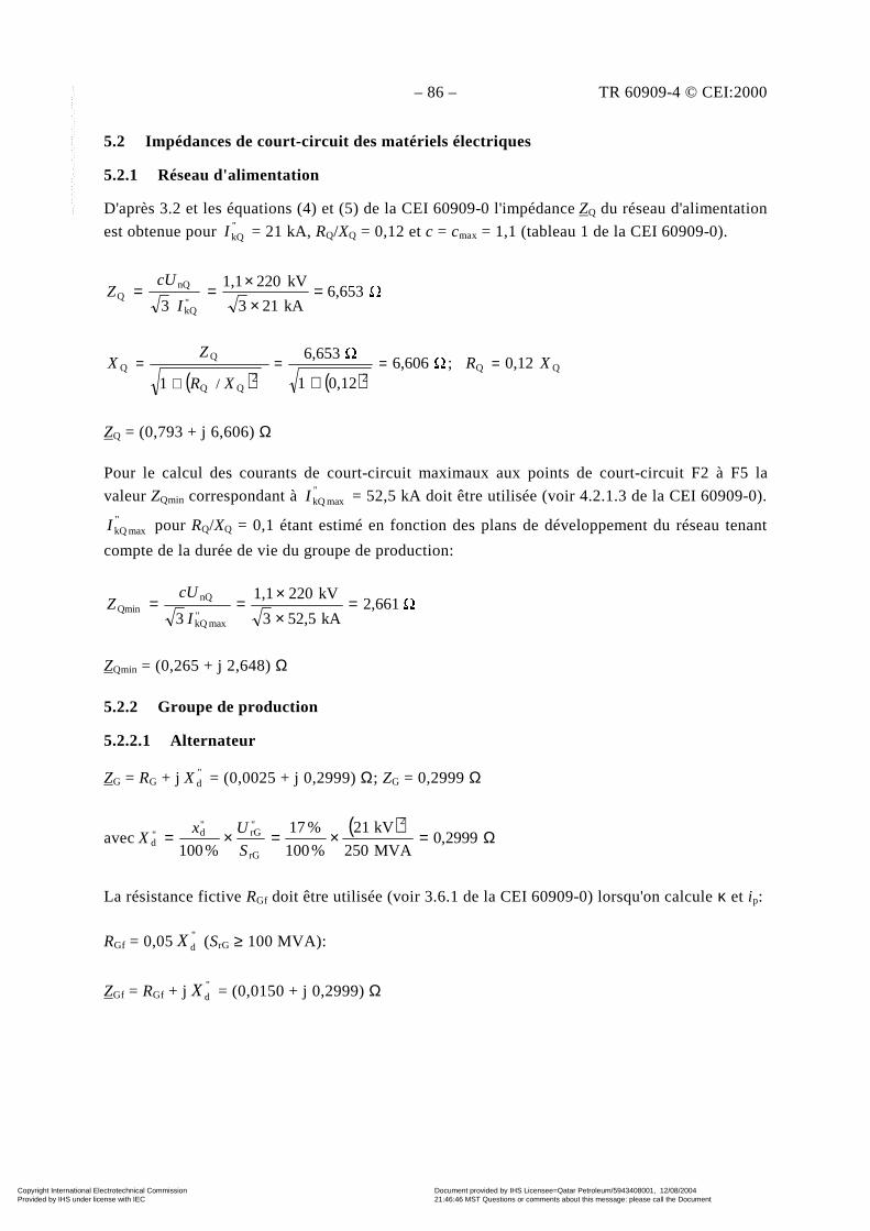
– 86 – TR 60909-4 © CEI:2000
5.2 Impédances de court-circuit des matériels électriques
5.2.1 Réseau d'alimentation
D'après 3.2 et les équations (4) et (5) de la CEI 60909-0 l'impédance ZQ du réseau d'alimentation
est obtenue pour "kQI = 21 kA, RQ/XQ = 0,12 et c = cmax = 1,1 (tableau 1 de la CEI 60909-0).
6,653kA213
kV2201,1
3 "kQ
nQQ =
××==
I
cUZ
QQ 0,12; 6,606
0,121
6,653
1 22/
XRXR
ZX ===
+=
+
ZQ = (0,793 + j 6,606) Ω
Pour le calcul des courants de court-circuit maximaux aux points de court-circuit F2 à F5 la
valeur ZQmin correspondant à " maxkQI = 52,5 kA doit être utilisée (voir 4.2.1.3 de la CEI 60909-0)."
maxkQI pour RQ/XQ = 0,1 étant estimé en fonction des plans de développement du réseau tenant
compte de la durée de vie du groupe de production:
2,661kA52,53
kV2201,1
3 "maxkQ
nQQmin =
××==
I
cUZ
ZQmin = (0,265 + j 2,648) Ω
5.2.2 Groupe de production
5.2.2.1 Alternateur
ZG = RG + j "dX = (0,0025 + j 0,2999) Ω; ZG = 0,2999 Ω
avec( )
Ω=×=×= 2999,0MVA250
kV21
%100
%17
%100
2
rG
"rG
"d"
dS
UxX
La résistance fictive RGf doit être utilisée (voir 3.6.1 de la CEI 60909-0) lorsqu'on calcule κ et ip:
RGf = 0,05 "dX (SrG ≥ 100 MVA):
ZGf = RGf + j "dX = (0,0150 + j 0,2999) Ω
Copyright International Electrotechnical Commission Provided by IHS under license with IEC
Document provided by IHS Licensee=Qatar Petroleum/5943408001, 12/08/200421:46:46 MST Questions or comments about this message: please call the DocumentPolicy Group at 303-397-2295.
--``,,,,,``,````,``,,,,`,```,``-`-`,,`,,`,`,,`---
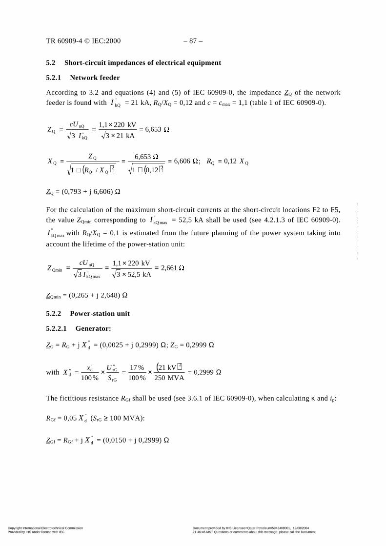
TR 60909-4 © IEC:2000 – 87 –
5.2 Short-circuit impedances of electrical equipment
5.2.1 Network feeder
According to 3.2 and equations (4) and (5) of IEC 60909-0, the impedance ZQ of the network
feeder is found with "kQI = 21 kA, RQ/XQ = 0,12 and c = cmax = 1,1 (table 1 of IEC 60909-0).
6,653kA213
kV2201,1
3 "kQ
nQQ =
××==
I
cUZ
QQ 0,12; 6,606
0,121
6,653
1 22/
XRXR
ZX ===
+=
+
ZQ = (0,793 + j 6,606) Ω
For the calculation of the maximum short-circuit currents at the short-circuit locations F2 to F5,
the value ZQmin corresponding to "maxkQI = 52,5 kA shall be used (see 4.2.1.3 of IEC 60909-0).
"maxkQI with RQ/XQ = 0,1 is estimated from the future planning of the power system taking into
account the lifetime of the power-station unit:
2,661kA52,53
kV2201,1
3 "maxkQ
nQQmin =
××==
I
cUZ
ZQmin = (0,265 + j 2,648) Ω
5.2.2 Power-station unit
5.2.2.1 Generator:
ZG = RG + j "dX = (0,0025 + j 0,2999) Ω; ZG = 0,2999 Ω
with ( )
Ω=×=×= 2999,0MVA250
kV21
%100
%17
%100
2
rG
"rG
"d"
dS
UxX
The fictitious resistance RGf shall be used (see 3.6.1 of IEC 60909-0), when calculating κ and ip:
RGf = 0,05 "dX (SrG ≥ 100 MVA):
ZGf = RGf + j "dX = (0,0150 + j 0,2999) Ω
Copyright International Electrotechnical Commission Provided by IHS under license with IEC
Document provided by IHS Licensee=Qatar Petroleum/5943408001, 12/08/200421:46:46 MST Questions or comments about this message: please call the DocumentPolicy Group at 303-397-2295.
--``,,,,,``,````,``,,,,`,```,``-`-`,,`,,`,`,,`---
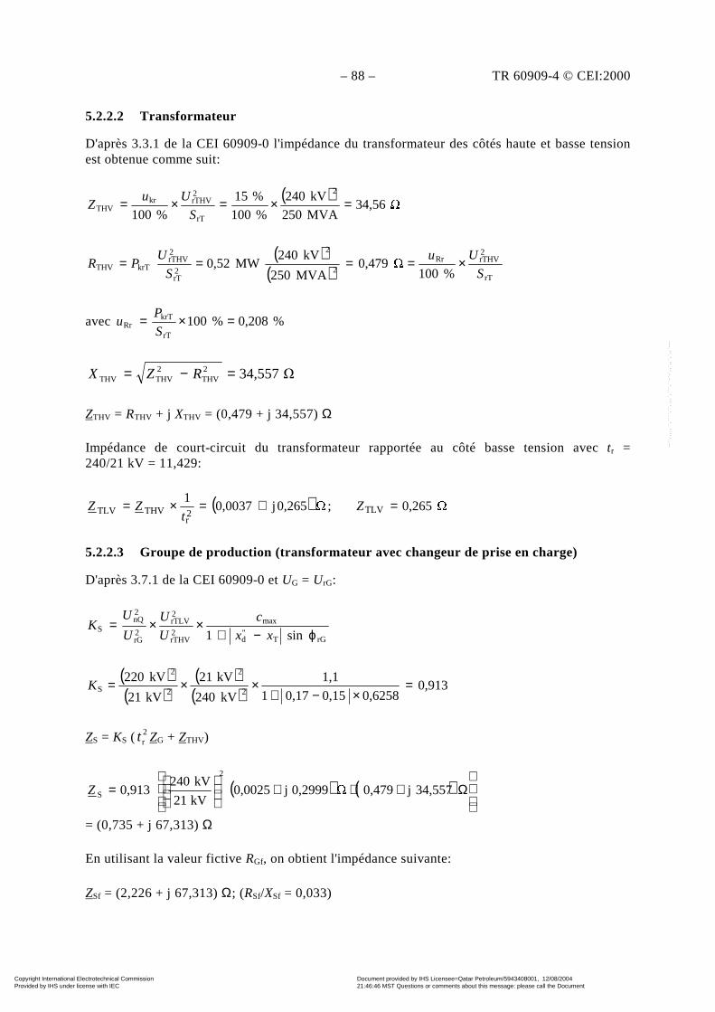
– 88 – TR 60909-4 © CEI:2000
5.2.2.2 Transformateur
D'après 3.3.1 de la CEI 60909-0 l'impédance du transformateur des côtés haute et basse tensionest obtenue comme suit:
( ) 34,56
MVA250
kV240
%100
%15
%100
2
rT
2rTHVkr
THV =×=×=S
UuZ
( )( ) rT
2rTHVRr
2
2
2rT
2rTHV
krTTHV%100
0,479MVA250
kV240MW0,52
S
Uu
S
UPR ×====
avec %0,208%100rT
krTRr =×=
S
Pu
34,5572THV
2THVTHV =−= RZX
ZTHV = RTHV + j XTHV = (0,479 + j 34,557) Ω
Impédance de court-circuit du transformateur rapportée au côté basse tension avec tr =240/21 kV = 11,429:
( ) 0,265; 0,265j0,00371
TLV2r
THVTLV =+=×= Zt
ZZ
5.2.2.3 Groupe de production (transformateur avec changeur de prise en charge)
D'après 3.7.1 de la CEI 60909-0 et UG = UrG:
rGT"d
max
2rTHV
2rTLV
2rG
2nQ
Ssin1 ϕ−+
××=xx
c
U
U
U
UK
( )( )
( )( )
0,9130,62580,150,171
1,1
kV240
kV21
kV21
kV2202
2
2
2
S =×−+
××=K
ZS = KS (2rt ZG + ZTHV)
( ) ( )
Ω+++
= 34,557j0,479 0,2999j0,0025
kV21
kV2400,913
2
SZ
= (0,735 + j 67,313) Ω
En utilisant la valeur fictive RGf, on obtient l'impédance suivante:
ZSf = (2,226 + j 67,313) Ω; (RSf/XSf = 0,033)
Copyright International Electrotechnical Commission Provided by IHS under license with IEC
Document provided by IHS Licensee=Qatar Petroleum/5943408001, 12/08/200421:46:46 MST Questions or comments about this message: please call the DocumentPolicy Group at 303-397-2295.
--``,,,,,``,````,``,,,,`,```,``-`-`,,`,,`,`,,`---
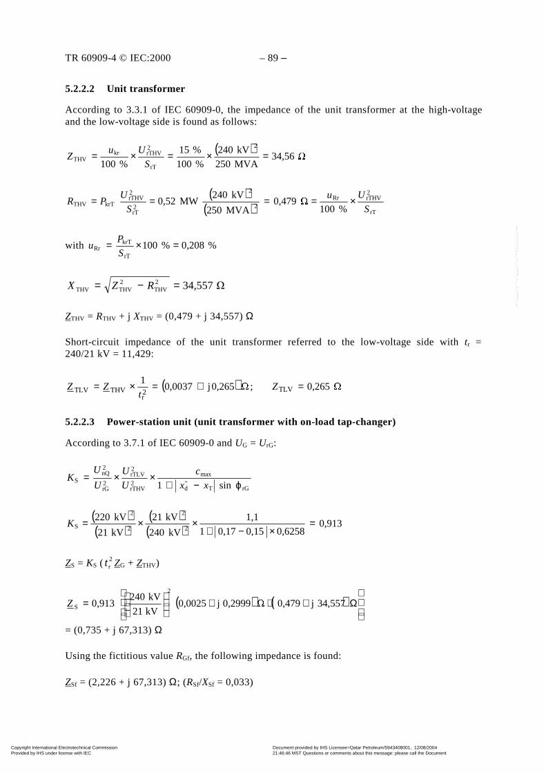
TR 60909-4 © IEC:2000 – 89 –
5.2.2.2 Unit transformer
According to 3.3.1 of IEC 60909-0, the impedance of the unit transformer at the high-voltageand the low-voltage side is found as follows:
( ) 34,56
MVA250
kV240
%100
%15
%100
2
rT
2rTHVkr
THV =×=×=S
UuZ
( )( ) rT
2rTHVRr
2
2
2rT
2rTHV
krTTHV%100
0,479MVA250
kV240MW0,52
S
Uu
S
UPR ×====
with %0,208%100rT
krTRr =×=
S
Pu
34,5572THV
2THVTHV =−= RZX
ZTHV = RTHV + j XTHV = (0,479 + j 34,557) Ω
Short-circuit impedance of the unit transformer referred to the low-voltage side with tr =240/21 kV = 11,429:
( ) 0,265; 0,265j0,00371
TLV2r
THVTLV =+=×= Zt
ZZ
5.2.2.3 Power-station unit (unit transformer with on-load tap-changer)
According to 3.7.1 of IEC 60909-0 and UG = UrG:
rGT"d
max
2rTHV
2rTLV
2rG
2nQ
Ssin1 ϕ−+
××=xx
c
U
U
U
UK
( )( )
( )( )
0,9130,62580,150,171
1,1
kV240
kV21
kV21
kV2202
2
2
2
S =×−+
××=K
ZS = KS (2rt ZG + ZTHV)
( ) ( )
Ω+++
= 34,557j0,479 0,2999j0,0025
kV21
kV2400,913
2
SZ
= (0,735 + j 67,313) Ω
Using the fictitious value RGf, the following impedance is found:
ZSf = (2,226 + j 67,313) Ω; (RSf/XSf = 0,033)
Copyright International Electrotechnical Commission Provided by IHS under license with IEC
Document provided by IHS Licensee=Qatar Petroleum/5943408001, 12/08/200421:46:46 MST Questions or comments about this message: please call the DocumentPolicy Group at 303-397-2295.
--``,,,,,``,````,``,,,,`,```,``-`-`,,`,,`,`,,`---
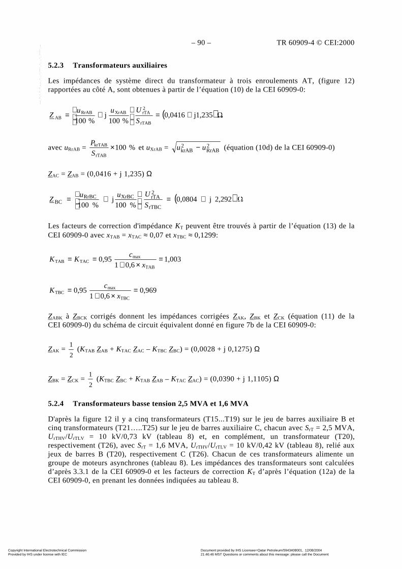
– 90 – TR 60909-4 © CEI:2000
5.2.3 Transformateurs auxiliaires
Les impédances de système direct du transformateur à trois enroulements AT, (figure 12)rapportées au côté A, sont obtenues à partir de l’équation (10) de la CEI 60909-0:
( ) 1,235j0,0416%100
j%100 rTAB
2rTAXrABRrAB
AB +=
+=
S
UuuZ
avec uRrAB = %100rTAB
krTAB ×S
P et uXrAB = 2
RrAB2krAB uu − (équation (10d) de la CEI 60909-0)
ZAC = ZAB = (0,0416 + j 1,235) Ω
( ) 2,292j0,0804%100
j%100 rTBC
2rTAXrBCRrBC
BC +=
+=
S
UuuZ
Les facteurs de correction d'impédance KT peuvent être trouvés à partir de l’équation (13) de laCEI 60909-0 avec xTAB = xTAC ≈ 0,07 et xTBC ≈ 0,1299:
1,0030,61
0,95TAB
maxTACTAB =
×+==
x
cKK
0,9690,61
0,95TBC
maxTBC =
×+=
x
cK
ZABK à ZBCK corrigés donnent les impédances corrigées ZAK, ZBK et ZCK (équation (11) de laCEI 60909-0) du schéma de circuit équivalent donné en figure 7b de la CEI 60909-0:
ZAK = 2
1 (KTAB ZAB + KTAC ZAC – KTBC ZBC) = (0,0028 + j 0,1275) Ω
ZBK = ZCK = 2
1 (KTBC ZBC + KTAB ZAB – KTAC ZAC) = (0,0390 + j 1,1105) Ω
5.2.4 Transformateurs basse tension 2,5 MVA et 1,6 MVA
D'après la figure 12 il y a cinq transformateurs (T15...T19) sur le jeu de barres auxiliaire B etcinq transformateurs (T21…..T25) sur le jeu de barres auxiliaire C, chacun avec SrT = 2,5 MVA,UrTHV/UrTLV = 10 kV/0,73 kV (tableau 8) et, en complément, un transformateur (T20),respectivement (T26), avec SrT = 1,6 MVA, UrTHV/UrTLV = 10 kV/0,42 kV (tableau 8), relié auxjeux de barres B (T20), respectivement C (T26). Chacun de ces transformateurs alimente ungroupe de moteurs asynchrones (tableau 8). Les impédances des transformateurs sont calculéesd’après 3.3.1 de la CEI 60909-0 et les facteurs de correction KT d’après l’équation (12a) de laCEI 60909-0, en prenant les données indiquées au tableau 8.
Copyright International Electrotechnical Commission Provided by IHS under license with IEC
Document provided by IHS Licensee=Qatar Petroleum/5943408001, 12/08/200421:46:46 MST Questions or comments about this message: please call the DocumentPolicy Group at 303-397-2295.
--``,,,,,``,````,``,,,,`,```,``-`-`,,`,,`,`,,`---
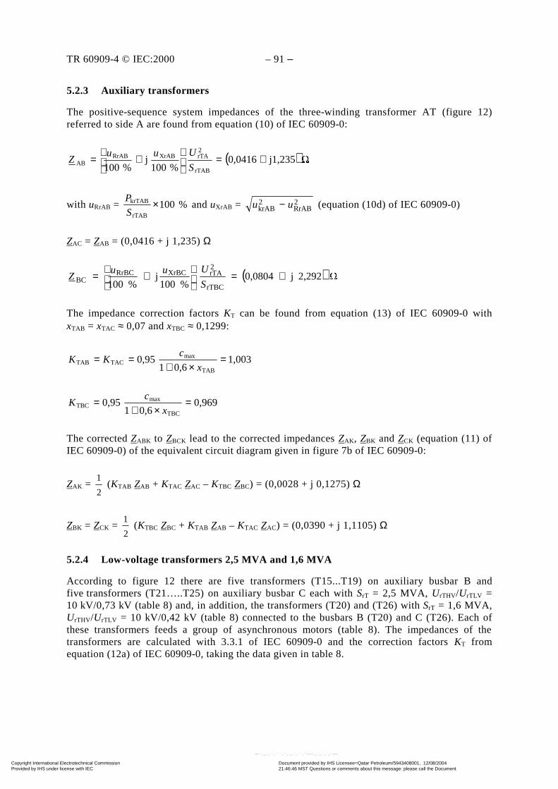
TR 60909-4 © IEC:2000 – 91 –
5.2.3 Auxiliary transformers
The positive-sequence system impedances of the three-winding transformer AT (figure 12)referred to side A are found from equation (10) of IEC 60909-0:
( ) 1,235j0,0416%100
j%100 rTAB
2rTAXrABRrAB
AB +=
+=
S
UuuZ
with uRrAB = %100rTAB
krTAB ×S
P and uXrAB = 2
RrAB2krAB uu − (equation (10d) of IEC 60909-0)
ZAC = ZAB = (0,0416 + j 1,235) Ω
( ) 2,292j0,0804%100
j%100 rTBC
2rTAXrBCRrBC
BC +=
+=
S
UuuZ
The impedance correction factors KT can be found from equation (13) of IEC 60909-0 withxTAB = xTAC ≈ 0,07 and xTBC ≈ 0,1299:
1,0030,61
0,95TAB
maxTACTAB =
×+==
x
cKK
0,9690,61
0,95TBC
maxTBC =
×+=
x
cK
The corrected ZABK to ZBCK lead to the corrected impedances ZAK, ZBK and ZCK (equation (11) ofIEC 60909-0) of the equivalent circuit diagram given in figure 7b of IEC 60909-0:
ZAK = 2
1 (KTAB ZAB + KTAC ZAC – KTBC ZBC) = (0,0028 + j 0,1275) Ω
ZBK = ZCK = 2
1 (KTBC ZBC + KTAB ZAB – KTAC ZAC) = (0,0390 + j 1,1105) Ω
5.2.4 Low-voltage transformers 2,5 MVA and 1,6 MVA
According to figure 12 there are five transformers (T15...T19) on auxiliary busbar B andfive transformers (T21…..T25) on auxiliary busbar C each with SrT = 2,5 MVA, UrTHV/UrTLV =10 kV/0,73 kV (table 8) and, in addition, the transformers (T20) and (T26) with SrT = 1,6 MVA,UrTHV/UrTLV = 10 kV/0,42 kV (table 8) connected to the busbars B (T20) and C (T26). Each ofthese transformers feeds a group of asynchronous motors (table 8). The impedances of thetransformers are calculated with 3.3.1 of IEC 60909-0 and the correction factors KT fromequation (12a) of IEC 60909-0, taking the data given in table 8.
Copyright International Electrotechnical Commission Provided by IHS under license with IEC
Document provided by IHS Licensee=Qatar Petroleum/5943408001, 12/08/200421:46:46 MST Questions or comments about this message: please call the DocumentPolicy Group at 303-397-2295.
--``,,,,,``,````,``,,,,`,```,``-`-`,,`,,`,`,,`---
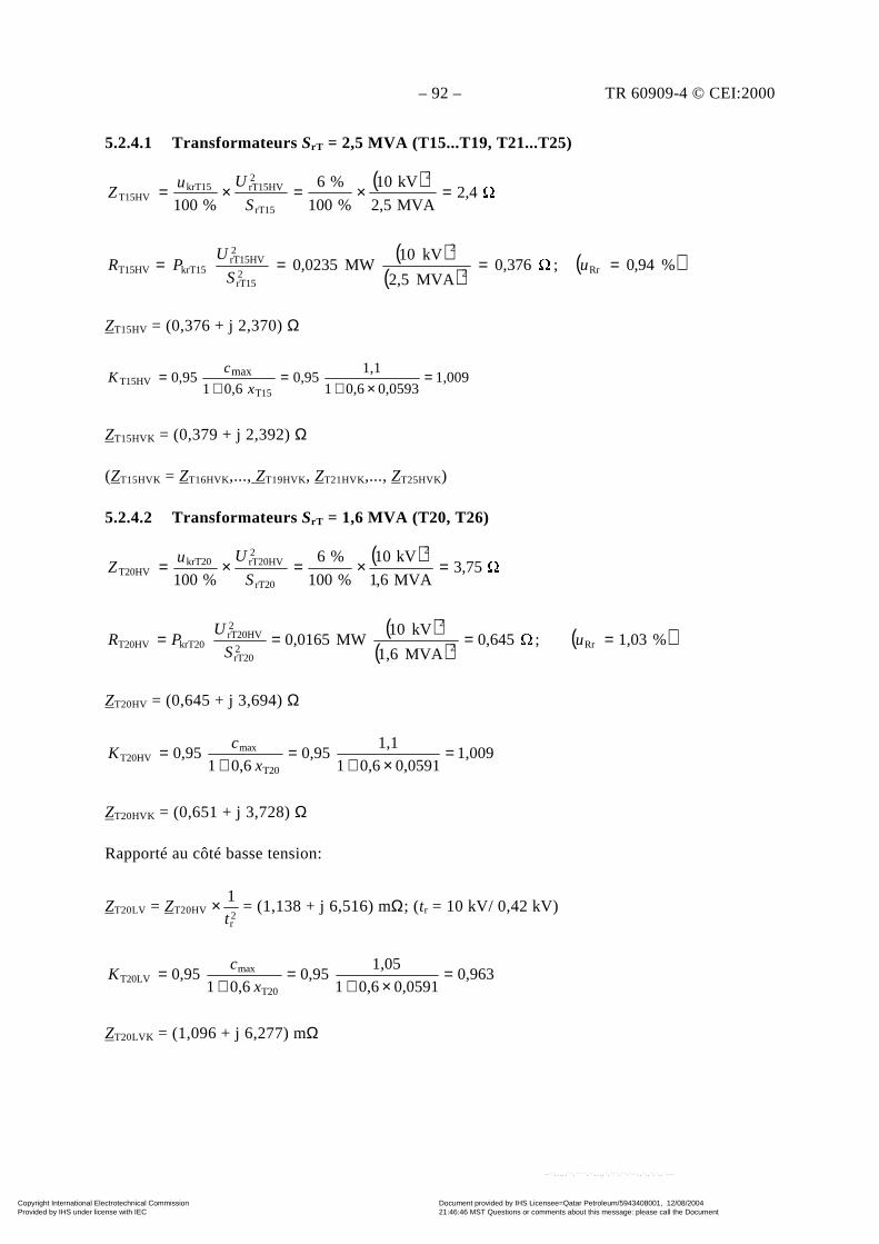
– 92 – TR 60909-4 © CEI:2000
5.2.4.1 Transformateurs SrT = 2,5 MVA (T15...T19, T21...T25)
( ) 2,4
MVA2,5
kV10
%100
%6
%100
2
rT15
2rT15HVkrT15
T15HV =×=×=S
UuZ
( )( )
( )%94,0; 0,376MVA2,5
kV10MW0,0235 Rr2
2
2rT15
2rT15HV
krT15T15HV ==== uS
UPR
ZT15HV = (0,376 + j 2,370) Ω
1,0090,05930,61
1,10,95
0,610,95
T15T15HV
max =×+
=+
=x
cK
ZT15HVK = (0,379 + j 2,392) Ω
(ZT15HVK = ZT16HVK,..., ZT19HVK, ZT21HVK,..., ZT25HVK)
5.2.4.2 Transformateurs SrT = 1,6 MVA (T20, T26)
( ) 3,75
MVA6,1
kV10
%100
%6
%100
2
rT20
2rT20HVkrT20
T20HV =×=×=S
UuZ
( )( )
( )%1,03; 0,645MVA1,6
kV10MW0,0165 Rr2
2
2rT20
2rT20HV
krT20T20HV ==== uS
UPR
ZT20HV = (0,645 + j 3,694) Ω
1,0090,05910,61
1,10,95
0,610,95
T20
maxT20HV =
×+=
+=
x
cK
ZT20HVK = (0,651 + j 3,728) Ω
Rapporté au côté basse tension:
ZT20LV = ZT20HV ×2r
1t
= (1,138 + j 6,516) mΩ; (tr = 10 kV/ 0,42 kV)
0,9630,05910,61
1,050,95
0,610,95
T20
maxT20LV =
×+=
+=
x
cK
ZT20LVK = (1,096 + j 6,277) mΩ
Copyright International Electrotechnical Commission Provided by IHS under license with IEC
Document provided by IHS Licensee=Qatar Petroleum/5943408001, 12/08/200421:46:46 MST Questions or comments about this message: please call the DocumentPolicy Group at 303-397-2295.
--``,,,,,``,````,``,,,,`,```,``-`-`,,`,,`,`,,`---
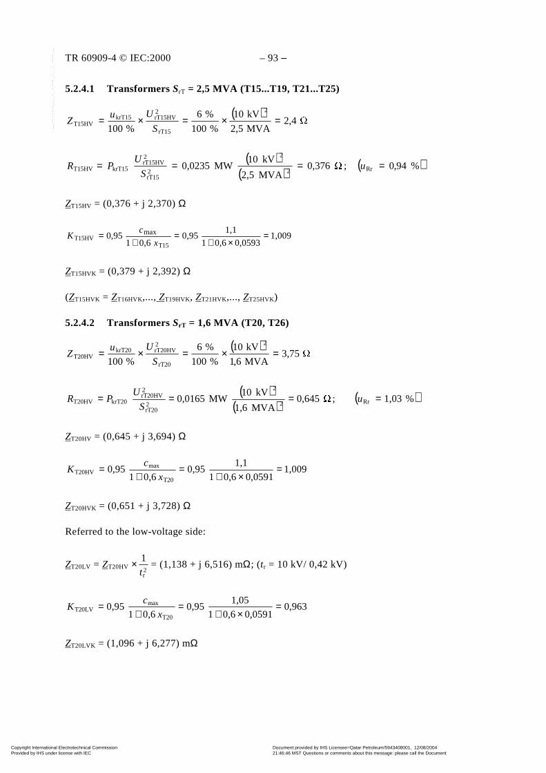
TR 60909-4 © IEC:2000 – 93 –
5.2.4.1 Transformers SrT = 2,5 MVA (T15...T19, T21...T25)
( ) 2,4
MVA2,5
kV10
%100
%6
%100
2
rT15
2rT15HVkrT15
T15HV =×=×=S
UuZ
( )( )
( )%94,0; 0,376MVA2,5
kV10MW0,0235 Rr2
2
2rT15
2rT15HV
krT15T15HV ==== uS
UPR
ZT15HV = (0,376 + j 2,370) Ω
1,0090,05930,61
1,10,95
0,610,95
T15T15HV
max =×+
=+
=x
cK
ZT15HVK = (0,379 + j 2,392) Ω
(ZT15HVK = ZT16HVK,..., ZT19HVK, ZT21HVK,..., ZT25HVK)
5.2.4.2 Transformers SrT = 1,6 MVA (T20, T26)
( ) 3,75
MVA6,1
kV10
%100
%6
%100
2
rT20
2rT20HVkrT20
T20HV =×=×=S
UuZ
( )( )
( )%1,03; 0,645MVA1,6
kV10MW0,0165 Rr2
2
2rT20
2rT20HV
krT20T20HV ==== uS
UPR
ZT20HV = (0,645 + j 3,694) Ω
1,0090,05910,61
1,10,95
0,610,95
T20
maxT20HV =
×+=
+=
x
cK
ZT20HVK = (0,651 + j 3,728) Ω
Referred to the low-voltage side:
ZT20LV = ZT20HV ×2r
1t
= (1,138 + j 6,516) mΩ; (tr = 10 kV/ 0,42 kV)
0,9630,05910,61
1,050,95
0,610,95
T20
maxT20LV =
×+=
+=
x
cK
ZT20LVK = (1,096 + j 6,277) mΩ
Copyright International Electrotechnical Commission Provided by IHS under license with IEC
Document provided by IHS Licensee=Qatar Petroleum/5943408001, 12/08/200421:46:46 MST Questions or comments about this message: please call the DocumentPolicy Group at 303-397-2295.
--``,,,,,``,````,``,,,,`,```,``-`-`,,`,,`,`,,`---
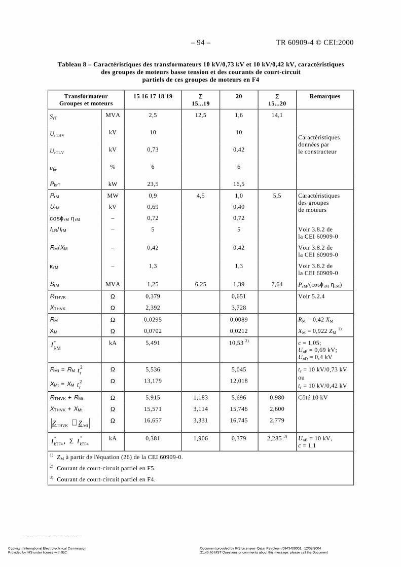
– 94 – TR 60909-4 © CEI:2000
Tableau 8 – Caractéristiques des transformateurs 10 kV/0,73 kV et 10 kV/0,42 kV, caractéristiquesdes groupes de moteurs basse tension et des courants de court-circuit
partiels de ces groupes de moteurs en F4
TransformateurGroupes et moteurs
15 16 17 18 19 Σ15...19
20 Σ15...20
Remarques
SrTMVA 2,5 12,5 1,6 14,1
UrTHVkV 10 10
UrTLVkV 0,73 0,42
ukr% 6 6
Caractéristiquesdonnées parle constructeur
PkrT kW 23,5 16,5
PrM MW 0,9 4,5 1,0 5,5
UrM kV 0,69 0,40
cosϕrM ηrM – 0,72 0,72
Caractéristiquesdes groupesde moteurs
ILR/IrM – 5 5 Voir 3.8.2 dela CEI 60909-0
RM/XM – 0,42 0,42 Voir 3.8.2 dela CEI 60909-0
κrM – 1,3 1,3 Voir 3.8.2 dela CEI 60909-0
SrM MVA 1,25 6,25 1,39 7,64 PrM/(cosϕrM ηrM)
RTHVK Ω 0,379 0,651 Voir 5.2.4
XTHVK Ω 2,392 3,728
RM Ω 0,0295 0,0089 RM = 0,42 XM
XM Ω 0,0702 0,0212 XM = 0,922 ZM 1)
"kM
I kA 5,491 10,53 2) c = 1,05;UnE = 0,69 kV;UnD = 0,4 kV
RMt = RM 2rt Ω 5,536 5,045
XMt = XM 2rt
Ω 13,179 12,018
tr = 10 kV/0,73 kVoutr = 10 kV/0,42 kV
RTHVK + RMt Ω 5,915 1,183 5,696 0,980
XTHVK + XMt Ω 15,571 3,114 15,746 2,600
Côté 10 kV
tMTHVK ZZ + Ω 16,657 3,331 16,745 2,779
,"
kTF4I Σ "kTF4I kA 0,381 1,906 0,379 2,285 3) UnB = 10 kV,
c = 1,1
1) ZM à partir de l'équation (26) de la CEI 60909-0.2) Courant de court-circuit partiel en F5.3) Courant de court-circuit partiel en F4.
Copyright International Electrotechnical Commission Provided by IHS under license with IEC
Document provided by IHS Licensee=Qatar Petroleum/5943408001, 12/08/200421:46:46 MST Questions or comments about this message: please call the DocumentPolicy Group at 303-397-2295.
--``,,,,,``,````,``,,,,`,```,``-`-`,,`,,`,`,,`---
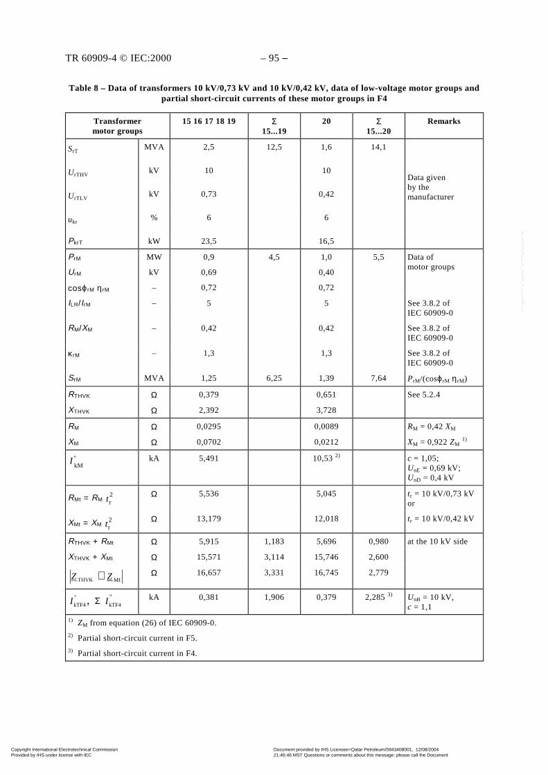
TR 60909-4 © IEC:2000 – 95 –
Table 8 – Data of transformers 10 kV/0,73 kV and 10 kV/0,42 kV, data of low-voltage motor groups andpartial short-circuit currents of these motor groups in F4
Transformermotor groups
15 16 17 18 19 Σ15...19
20 Σ15...20
Remarks
SrTMVA 2,5 12,5 1,6 14,1
UrTHVkV 10 10
UrTLVkV 0,73 0,42
ukr% 6 6
Data givenby themanufacturer
PkrT kW 23,5 16,5
PrM MW 0,9 4,5 1,0 5,5
UrM kV 0,69 0,40
Data ofmotor groups
cosϕrM ηrM – 0,72 0,72
ILR/IrM – 5 5 See 3.8.2 ofIEC 60909-0
RM/XM – 0,42 0,42 See 3.8.2 ofIEC 60909-0
κrM – 1,3 1,3 See 3.8.2 ofIEC 60909-0
SrM MVA 1,25 6,25 1,39 7,64 PrM/(cosϕrM ηrM)
RTHVK Ω 0,379 0,651 See 5.2.4
XTHVK Ω 2,392 3,728
RM Ω 0,0295 0,0089 RM = 0,42 XM
XM Ω 0,0702 0,0212 XM = 0,922 ZM 1)
"kM
I kA 5,491 10,53 2) c = 1,05;UnE = 0,69 kV;UnD = 0,4 kV
RMt = RM 2rt
Ω 5,536 5,045 tr = 10 kV/0,73 kVor
XMt = XM 2rt
Ω 13,179 12,018 tr = 10 kV/0,42 kV
RTHVK + RMt Ω 5,915 1,183 5,696 0,980
XTHVK + XMt Ω 15,571 3,114 15,746 2,600
at the 10 kV side
tMTHVK ZZ + Ω 16,657 3,331 16,745 2,779
,"
kTF4I Σ "kTF4I kA 0,381 1,906 0,379 2,285 3) UnB = 10 kV,
c = 1,1
1) ZM from equation (26) of IEC 60909-0.2) Partial short-circuit current in F5.3) Partial short-circuit current in F4.
Copyright International Electrotechnical Commission Provided by IHS under license with IEC
Document provided by IHS Licensee=Qatar Petroleum/5943408001, 12/08/200421:46:46 MST Questions or comments about this message: please call the DocumentPolicy Group at 303-397-2295.
--``,,,,,``,````,``,,,,`,```,``-`-`,,`,,`,`,,`---
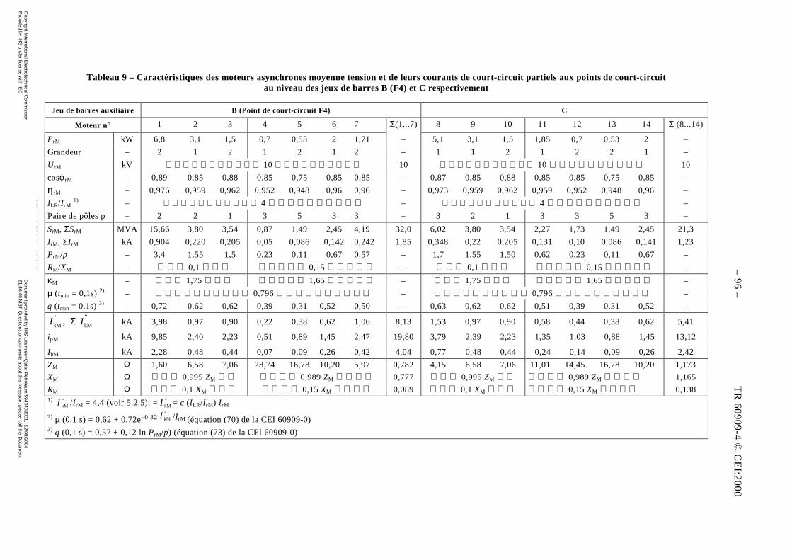
– 44 – TR 60909-4 © CEI:2000
Tableau 9 – Caractéristiques des moteurs asynchrones moyenne tension et de leurs courants de court-circuit partiels aux points de court-circuitau niveau des jeux de barres B (F4) et C respectivement
Jeu de barres auxiliaire B (Point de court-circuit F4) C
Moteur n° 1 2 3 4 5 6 7 Σ(1...7) 8 9 10 11 12 13 14 Σ (8...14)
PrM kW 6,8 3,1 1,5 0,7 0,53 2 1,71 – 5,1 3,1 1,5 1,85 0,7 0,53 2 –
Grandeur – 2 1 2 1 2 1 2 – 1 1 2 1 2 2 1 –
UrM kV 10 10 10 10
cosϕrM – 0,89 0,85 0,88 0,85 0,75 0,85 0,85 – 0,87 0,85 0,88 0,85 0,85 0,75 0,85 –
ηrM – 0,976 0,959 0,962 0,952 0,948 0,96 0,96 – 0,973 0,959 0,962 0,959 0,952 0,948 0,96 –
ILR/I rM 1) – 4 – 4 –
Paire de pôles p – 2 2 1 3 5 3 3 – 3 2 1 3 3 5 3 –
SrM, ΣSrM MVA 15,66 3,80 3,54 0,87 1,49 2,45 4,19 32,0 6,02 3,80 3,54 2,27 1,73 1,49 2,45 21,3
I rM, ΣI rM kA 0,904 0,220 0,205 0,05 0,086 0,142 0,242 1,85 0,348 0,22 0,205 0,131 0,10 0,086 0,141 1,23
PrM/p – 3,4 1,55 1,5 0,23 0,11 0,67 0,57 – 1,7 1,55 1,50 0,62 0,23 0,11 0,67 –
RM/XM – 0,1 0,15 – 0,1 0,15 –
κM – 1,75 1,65 – 1,75 1,65 –
µ (tmin = 0,1s) 2) – 0,796 – 0,796 –
q (tmin = 0,1s) 3) – 0,72 0,62 0,62 0,39 0,31 0,52 0,50 – 0,63 0,62 0,62 0,51 0,39 0,31 0,52 –
,"
kMI Σ "kMI kA 3,98 0,97 0,90 0,22 0,38 0,62 1,06 8,13 1,53 0,97 0,90 0,58 0,44 0,38 0,62 5,41
ipM kA 9,85 2,40 2,23 0,51 0,89 1,45 2,47 19,80 3,79 2,39 2,23 1,35 1,03 0,88 1,45 13,12
IbM kA 2,28 0,48 0,44 0,07 0,09 0,26 0,42 4,04 0,77 0,48 0,44 0,24 0,14 0,09 0,26 2,42
ZM Ω 1,60 6,58 7,06 28,74 16,78 10,20 5,97 0,782 4,15 6,58 7,06 11,01 14,45 16,78 10,20 1,173
XM Ω 0,995 ZM 0,989 ZM 0,777 0,995 ZM 0,989 ZM 1,165
RM Ω 0,1 XM 0,15 XM 0,089 0,1 XM 0,15 XM 0,1381) "
kMI /I rM = 4,4 (voir 5.2.5); = "kMI = c (ILR/I rM) I rM
2) µ (0,1 s) = 0,62 + 0,72e–0,32"kMI /I rM (équation (70) de la CEI 60909-0)
3) q (0,1 s) = 0,57 + 0,12 ln PrM/p) (équation (73) de la CEI 60909-0)
– 9
6 –
TR
60
90
9-4
© C
EI:2
00
0
Copyright International E
lectrotechnical Com
mission
Provided by IH
S under license w
ith IEC
Docum
ent provided by IHS
Licensee=Q
atar Petroleum
/5943408001, 12/08/200421:46:46 M
ST
Questions or com
ments about this m
essage: please call the Docum
entP
olicy Group at 303-397-2295.
--``,,,,,``,````,``,,,,`,```,``-`-`,,`,,`,`,,`---
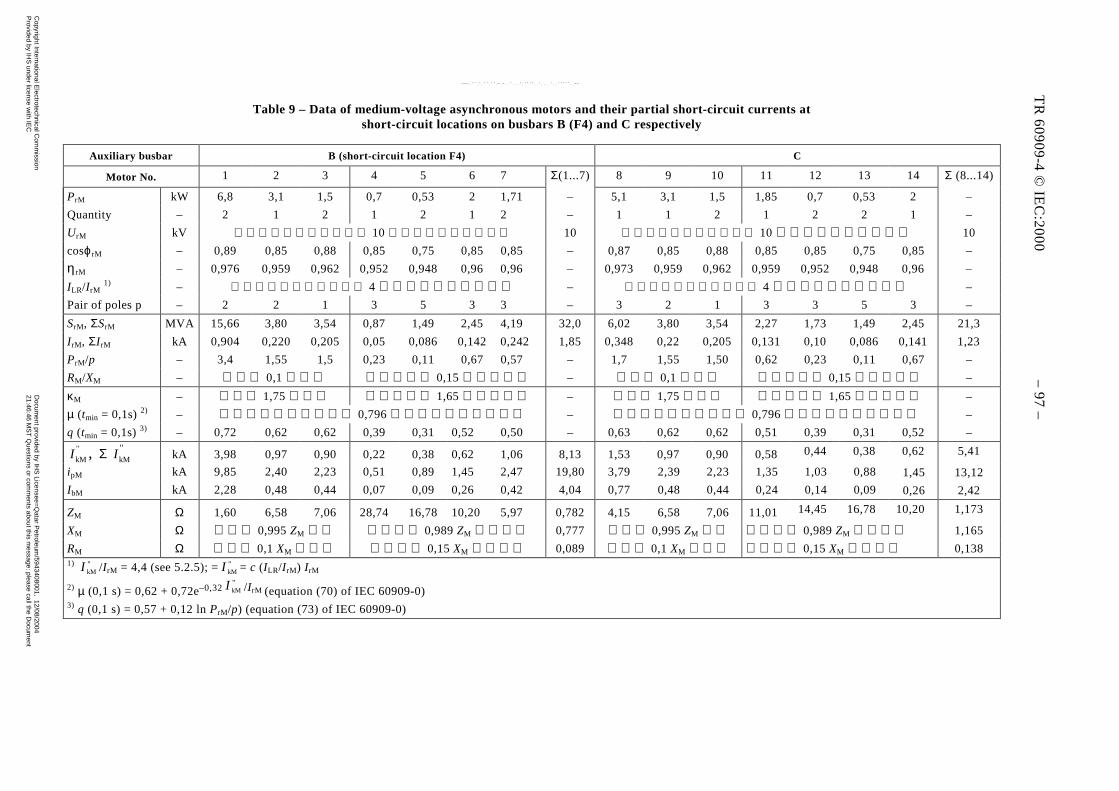
TR 60909-4 © IEC:2000 – 95 –
Table 9 – Data of medium-voltage asynchronous motors and their partial short-circuit currents atshort-circuit locations on busbars B (F4) and C respectively
Auxiliary busbar B (short-circuit location F4) C
Motor No. 1 2 3 4 5 6 7 Σ(1...7) 8 9 10 11 12 13 14 Σ (8...14)
PrM kW 6,8 3,1 1,5 0,7 0,53 2 1,71 – 5,1 3,1 1,5 1,85 0,7 0,53 2 –
Quantity – 2 1 2 1 2 1 2 – 1 1 2 1 2 2 1 –
UrM kV 10 10 10 10
cosϕrM – 0,89 0,85 0,88 0,85 0,75 0,85 0,85 – 0,87 0,85 0,88 0,85 0,85 0,75 0,85 –
ηrM – 0,976 0,959 0,962 0,952 0,948 0,96 0,96 – 0,973 0,959 0,962 0,959 0,952 0,948 0,96 –
ILR/I rM 1) – 4 – 4 –
Pair of poles p – 2 2 1 3 5 3 3 – 3 2 1 3 3 5 3 –
SrM, ΣSrM MVA 15,66 3,80 3,54 0,87 1,49 2,45 4,19 32,0 6,02 3,80 3,54 2,27 1,73 1,49 2,45 21,3
I rM, ΣI rM kA 0,904 0,220 0,205 0,05 0,086 0,142 0,242 1,85 0,348 0,22 0,205 0,131 0,10 0,086 0,141 1,23
PrM/p – 3,4 1,55 1,5 0,23 0,11 0,67 0,57 – 1,7 1,55 1,50 0,62 0,23 0,11 0,67 –
RM/XM – 0,1 0,15 – 0,1 0,15 –
κM – 1,75 1,65 – 1,75 1,65 –
µ (tmin = 0,1s) 2) – 0,796 – 0,796 –
q (tmin = 0,1s) 3) – 0,72 0,62 0,62 0,39 0,31 0,52 0,50 – 0,63 0,62 0,62 0,51 0,39 0,31 0,52 –
,"
kMI Σ "kMI kA 3,98 0,97 0,90 0,22 0,38 0,62 1,06 8,13 1,53 0,97 0,90 0,580,44 0,38 0,62 5,41
ipM kA 9,85 2,40 2,23 0,51 0,89 1,45 2,47 19,80 3,79 2,39 2,23 1,35 1,03 0,88 1,45 13,12
IbM kA 2,28 0,48 0,44 0,07 0,09 0,26 0,42 4,04 0,77 0,48 0,44 0,24 0,14 0,09 0,26 2,42
ZM Ω 1,60 6,58 7,06 28,74 16,78 10,20 5,97 0,782 4,15 6,58 7,06 11,01 14,45 16,78 10,20 1,173
XM Ω 0,995 ZM 0,989 ZM 0,777 0,995 ZM 0,989 ZM 1,165
RM Ω 0,1 XM 0,15 XM 0,089 0,1 XM 0,15 XM 0,1381) "
kMI /I rM = 4,4 (see 5.2.5); ="kMI = c (ILR/I rM) I rM
2) µ (0,1 s) = 0,62 + 0,72e–0,32"kMI /I rM (equation (70) of IEC 60909-0)
3) q (0,1 s) = 0,57 + 0,12 ln PrM/p) (equation (73) of IEC 60909-0)
TR
60
90
9-4
© IE
C:2
00
0 –
97
–
Copyright International E
lectrotechnical Com
mission
Provided by IH
S under license w
ith IEC
Docum
ent provided by IHS
Licensee=Q
atar Petroleum
/5943408001, 12/08/200421:46:46 M
ST
Questions or com
ments about this m
essage: please call the Docum
entP
olicy Group at 303-397-2295.
--``,,,,,``,````,``,,,,`,```,``-`-`,,`,,`,`,,`---

– 98 – TR 60909-4 © CEI:2000
5.2.5 Moteurs asynchrones
Les caractéristiques et les impédances de court-circuit des moteurs moyenne tension M1...M7reliés au jeu de barres B et les moteurs M8...M14 reliés au jeu de barres C à la figure 12 sontdonnées dans le tableau 9. En utilisant les équations (26) et (91) de la CEI 60909-0 et enconsidérant que UrM = Un dans ce cas, l'équation suivante, utilisée au tableau 9, peut être obtenue
pour le calcul de "kMI :
rMrM
LR
rM
rM
rM
LRn
M
n"kM
3/33I
I
Ic
U
I
I
IcU
Z
cUI ×=××==
Les caractéristiques et les impédances de court-circuit des groupes de moteurs basse tension sontdonnées au tableau 8. Ce tableau indique également les courants de court-circuit partiels desgroupes de moteurs (M15 à M20) du côté haute tension des transformateurs T15 à T20 dans lecas d'un court-circuit en F4 (jeu de barres B à la figure 12).
5.3 Calcul des courants de court-circuit
5.3.1 Point de court-circuit F1
Le courant de court-circuit "kI en F1 peut être calculé comme la somme de "kQI et
"kSI . Le
courant "kSI doit être calculé avec Zs d'après l’équation (21) de la CEI 60909-0 pour un groupe de
production avec changeur de prise en charge. Il n'est pas nécessaire de tenir compte des moteurs
asynchrones du réseau auxiliaire parce que leur contribution globale est inférieure à 1 % de "kI
dans ce cas (voir 5.3.3).
5.3.1.1 Courant de court-circuit initial "I k
( )( ) kA850,20j502,2
6,606j0,7933
kV2201,1
3 Q
nQ"kQ −=
+×==
Z
cUI
( )( ) kA2,075j0,023
67,313j0,7353
kV2201,1
3 S
nQ"kS −=
+×==
Z
cUI
( ) kA23,064kA;22,925j2,525 "k
"kS
"kQ
"k =−=+= IIII
5.3.1.2 Courant de court-circuit de crête ip
A partir de l'impédance ZQ on obtient RQ/XQ = 0,12 et κQ = 1,704. A partir de l'impédance ZSf
(voir 5.2.2) on trouve le rapport RSf/XSf = 0,033 et κS = 1,908.
ip = ipQ + ipS = κQ 2"kQI + κS 2 "
kSI
= 1,704 ×× 2 21 kA + 1,908 ×× 2 2,075 kA = 56,21 kA
Copyright International Electrotechnical Commission Provided by IHS under license with IEC
Document provided by IHS Licensee=Qatar Petroleum/5943408001, 12/08/200421:46:46 MST Questions or comments about this message: please call the DocumentPolicy Group at 303-397-2295.
--``,,,,,``,````,``,,,,`,```,``-`-`,,`,,`,`,,`---

TR 60909-4 © IEC:2000 – 99 –
5.2.5 Asynchronous motors
Data and short-circuit impedances of the medium-voltage motors M1...M7 connected to busbar Band motors M8...M14 connected to busbar C in figure 12 are given in table 9. Using equations(26) and (91) of IEC 60909-0 and bearing in mind that UrM = Un in this case, the following
equation, used in table 9, can be found for the calculation of "kMI :
rMrM
LR
rM
rM
rM
LRn
M
n"kM
3/33I
I
Ic
U
I
I
IcU
Z
cUI ×=××==
Data and short-circuit impedances of the low-voltage motor groups are given in table 8. Thistable gives also the partial short-circuit currents of the motor groups (M15 to M20) at the high-voltage side of the transformers T15 to T20 in the case of a short circuit in F4 (busbar B infigure 12).
5.3 Calculation of short-circuit currents
5.3.1 Short-circuit location F1
The short-circuit current "kI in F1 can be calculated as the sum of
"kQI and
"kSI . The current
"kSI
is to be calculated with ZS according to equation (21) of IEC 60909-0 for a power-station unitwith on-load tap-changer. It is not necessary to take the asynchronous motors of the auxiliary
network into account, because their overall contribution is smaller than 1 % of "kI in this case
(see 5.3.3).
5.3.1.1 Initial short-circuit current "kI
( )( ) kA850,20j502,2
6,606j0,7933
kV2201,1
3 Q
nQ"kQ −=
+×==
Z
cUI
( )( ) kA2,075j0,023
67,313j0,7353
kV2201,1
3 S
nQ"kS −=
+×==
Z
cUI
( ) kA23,064kA;22,925j2,525 "k
"kS
"kQ
"k =−=+= IIII
5.3.1.2 Peak short-circuit current ip
From the impedance ZQ it follows that RQ/XQ = 0,12 and κQ = 1,704. From the impedance ZSf
(see 5.2.2) the ratio RSf/XSf = 0,033 is found and κS = 1,908.
ip = ipQ + ipS = κQ 2"kQI + κS 2 "
kSI
= 1,704 ×× 2 21 kA + 1,908 ×× 2 2,075 kA = 56,21 kA
Copyright International Electrotechnical Commission Provided by IHS under license with IEC
Document provided by IHS Licensee=Qatar Petroleum/5943408001, 12/08/200421:46:46 MST Questions or comments about this message: please call the DocumentPolicy Group at 303-397-2295.
--``,,,,,``,````,``,,,,`,```,``-`-`,,`,,`,`,,`---
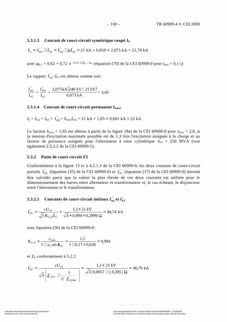
– 100 – TR 60909-4 © CEI:2000
5.3.1.3 Courant de court-circuit symétrique coupé I b
=+=+= "kS
"kQbSbQb IIIII 21 kA + 0,859 × 2,075 kA = 22,78 kA
avec µ0,1 = 0,62 + 0,72 rG/"kG32,0e II×− (équation (70) de la CEI 60909-0 pour tmin = 0,1 s)
Le rapport "kGI /I rG est obtenu comme suit:
( )3,45=
kA6,873
kV21/kV240kA2,075==
rG
"kSt
rG
"kG
I
I
I
I
5.3.1.4 Courant de court-circuit permanent I kmax
Ik = IkQ + IkS = "kQI + λmaxI rGt = 21 kA + 1,65 × 0,601 kA ≈ 22 kA
Le facteur λmax = 1,65 est obtenu à partir de la figure 18a) de la CEI 60909-0 pour xdsat = 2,0, sila tension d'excitation maximale possible est de 1,3 fois l'excitation assignée à la charge et aufacteur de puissance assignés pour l'alternateur à rotor cylindrique SrG = 250 MVA (voirégalement 2.5.2.2 de la CEI 60909-1).
5.3.2 Point de court-circuit F2
Conformément à la figure 13 et à 4.2.1.3 de la CEI 60909-0, les deux courants de court-circuit
partiels "kGI (équation (35) de la CEI 60909-0) et "
kTI (équation (37) de la CEI 60909-0) doiventêtre calculés parce que la valeur la plus élevée de ces deux courants est utilisée pour ledimensionnement des barres entre alternateur et transformateur et, le cas échéant, le disjoncteurentre l'alternateur et le transformateur.
5.3.2.1 Courants de court-circuit initiaux "kGI et "
kTI
kA44,74 0,29990,9943
kV211,1
3 GSG,
rG"kG =
×××==
ZK
cUI
avec équation (36) de la CEI 60909-0:
0,9940,6260,171
1,1
sin1 rG"d
maxSG, =
×+=
ϕ+=
x
cK
et ZG conformément à 5.2.2
kA46,79 0,285j0,00573
kV211,1
13
minQ2r
TLV
rG"kT =
+×
=
+
=
ZtZ
cUI
Copyright International Electrotechnical Commission Provided by IHS under license with IEC
Document provided by IHS Licensee=Qatar Petroleum/5943408001, 12/08/200421:46:46 MST Questions or comments about this message: please call the DocumentPolicy Group at 303-397-2295.
--``,,,,,``,````,``,,,,`,```,``-`-`,,`,,`,`,,`---
TR 60909-4 © IEC:2000 – 101 –
5.3.1.3 Symmetrical short-circuit breaking current I b
=+=+= "kS
"kQbSbQb IIIII 21 kA + 0,859 × 2,075 kA = 22,78 kA
with µ0,1 = 0,62 + 0,72 rG/"kG32,0e II×− (equation (70) of IEC 60909-0 for tmin = 0,1 s)
The ratio "kGI /I rG is found as follows:
( )3,45=
kA6,873
kV21/kV240kA2,075==
rG
"kSt
rG
"kG
I
I
I
I
5.3.1.4 Steady-state short-circuit current I kmax
Ik = IkQ + IkS = "kQI + λmaxI rGt = 21 kA + 1,65 × 0,601 kA ≈ 22 kA
The factor λmax = 1,65 is found from figure 18a) of IEC 60909-0 for xdsat = 2,0, if the highestpossible excitation voltage is 1,3 times the rated excitation at rated load and power factor for thecylindrical rotor generator SrG = 250 MVA (see also 2.5.2.2 of IEC 60909-1).
5.3.2 Short-circuit location F2
In accordance with figure 13 and 4.2.1.3 of IEC 60909-0, both the partial short-circuit currents"kGI (equation (35) of IEC 60909-0) and "
kTI (equation (37) of IEC 60909-0) are to be calculated,because the highest value of these two currents is used for the dimensioning of the bars betweengenerator and unit transformer and, when present, the circuit-breaker between generator and unittransformer.
5.3.2.1 Initial short-circuit currents "kGI and "
kTI
kA44,74 0,29990,9943
kV211,1
3 GSG,
rG"kG =
×××==
ZK
cUI
with equation (36) of IEC 60909-0:
0,9940,6260,171
1,1
sin1 rG"d
maxSG, =
×+=
ϕ+=
x
cK
and ZG according to 5.2.2
kA46,79 0,285j0,00573
kV211,1
13
minQ2r
TLV
rG"kT =
+×
=
+
=
ZtZ
cUI
Copyright International Electrotechnical Commission Provided by IHS under license with IEC
Document provided by IHS Licensee=Qatar Petroleum/5943408001, 12/08/200421:46:46 MST Questions or comments about this message: please call the DocumentPolicy Group at 303-397-2295.
--``,,,,,``,````,``,,,,`,```,``-`-`,,`,,`,`,,`---

– 102 – TR 60909-4 © CEI:2000
avec ZQmin = (0,265 + j 2,648) Ω à partir de 5.2.1, ZTLV = (0,0037 + j 0,265) Ω à partir de 5.2.2 ettr = 240 kV/21 kV.
Le courant total pour le dimensionnement des barres entre le générateur et le transformateur est
obtenu à partir de l'addition de "ATkM,
"kT et II calculée en 5.3.3.
=+ "ATkM,
"kT II (46,79 + 6,35) kA = 53,14 kA
=+ "ATkM,
"kT II 1,76 – j 53,08kA = 53,11 kA
5.3.2.2 Courants de court-circuit de crête ipG et ipT
ipG = κG 2 kA117,69kA44,7421,86"kG =××=I
avec R/X = RGf /"dX = 0,05 et κG = 1,86 (équation (55) de la CEI 60909-0).
ipT = κT 2 kA128,37kA46,7921,94"kT =××=I
avec R/X = 0,0057 Ω/0,285 Ω = 0,02 et κT = 1,94
5.3.2.3 Courants de court-circuit symétriques coupés I bG et I bT
IbG = µ kA31,77kA44,740,71"kG =×=I
avec µ = 0,62 + 0,72 rG/"kG0,32e II×− = 0,71; tmin = 0,1 s
à "kGI /I rG = 44,74 kA/6,87 kA = 6,51
IbT = "kTI (court-circuit éloigné d'un alternateur (équation (65) de la CEI 60909-0)).
5.3.2.4 Courants de court-circuit permanents I kGmax et I kTmax
IkGmax = λmaxI rG = 1,75 × 6,87 kA = 12,0 kA
avec λmax = 1,75 à partir de la figure 18a de la CEI 60909-0 obtenu avec"kGI /I rG = 6,51.
IkTmax = "kTI (court-circuit éloigné d'un alternateur (équation (84) de la CEI 60909-0)).
En tenant compte de la contribution des moteurs alimentés par le transformateur auxiliaire AT(voir 5.3.3) on obtient les courants suivants pour le dimensionnement des barres entre legénérateur et le transformateur:
=+ ATpM,pT ii (128,37 + 15,09) kA = 143,46 kA
=+≈+ "ATkM,
"kTATbM,bT IIII 53,14 kA du côté conservateur
Copyright International Electrotechnical Commission Provided by IHS under license with IEC
Document provided by IHS Licensee=Qatar Petroleum/5943408001, 12/08/200421:46:46 MST Questions or comments about this message: please call the DocumentPolicy Group at 303-397-2295.
--``,,,,,``,````,``,,,,`,```,``-`-`,,`,,`,`,,`---

TR 60909-4 © IEC:2000 – 103 –
with ZQmin = (0,265 + j 2,648) Ω from 5.2.1, ZTLV = (0,0037 + j 0,265) Ω from 5.2.2 andtr = 240 kV/21 kV.
The total current for the dimensioning of the bars between generator and the unit transformer is
found from the addition of "ATkM,
"kT and II calculated in 5.3.3:
=+ "ATkM,
"kT II (46,79 + 6,35) kA = 53,14 kA
=+ "ATkM,
"kT II 1,76 – j 53,08kA = 53,11 kA
5.3.2.2 Peak short-circuit currents ipG and ipT
ipG = κG 2 kA117,69kA44,7421,86"kG =××=I
with R/X = RGf /"dX = 0,05 and κG = 1,86 (equation (55) of IEC 60909-0).
ipT = κT 2 kA128,37kA46,7921,94"kT =××=I
with R/X = 0,0057 Ω/0,285 Ω = 0,02 and κT = 1,94
5.3.2.3 Symmetrical short-circuit breaking currents I bG and I bT
IbG = µ kA31,77kA44,740,71"kG =×=I
with µ = 0,62 + 0,72 rG/"kG0,32e II×− = 0,71; tmin = 0,1 s
at "kGI /I rG = 44,74 kA/6,87 kA = 6,51
IbT = "kTI (far-from-generator short circuit (equation (65) of IEC 60909-0)).
5.3.2.4 Steady-state short-circuit currents I kGmax and I kTmax
IkGmax = λmaxI rG = 1,75 × 6,87 kA = 12,0 kA
with λmax = 1,75 from figure 18a of IEC 60909-0 found with "kGI /I rG = 6,51.
IkTmax = "kTI (far-from-generator short circuit (equation (84) of IEC 60909-0)).
Taking care of the contribution from the motors fed through the auxiliary transformer AT(see 5.3.3), the following currents for the dimensioning of the bars between generator and unittransformer are found:
=+ ATpM,pT ii (128,37 + 15,09) kA = 143,46 kA
=+≈+ "ATkM,
"kTATbM,bT IIII 53,14 kA at the conservative side.
Copyright International Electrotechnical Commission Provided by IHS under license with IEC
Document provided by IHS Licensee=Qatar Petroleum/5943408001, 12/08/200421:46:46 MST Questions or comments about this message: please call the DocumentPolicy Group at 303-397-2295.
--``,,,,,``,````,``,,,,`,```,``-`-`,,`,,`,`,,`---
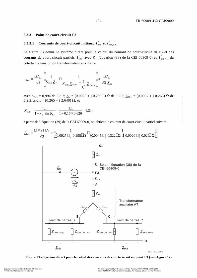
– 104 – TR 60909-4 © CEI:2000
5.3.3 Point de court-circuit F3
5.3.3.1 Courants de court-circuit initiaux "" I I ATkM,krsl et
La figure 13 donne le système direct pour le calcul du courant de court-circuit en F3 et des
courants de court-circuit partiels "krslI avec Zrsl (équation (38) de la CEI 60909-0) et "
AT,kMI du
côté haute tension du transformateur auxiliaire.
rsl
rG
Qmin2r
TLVST,GSG,
rG"krsl
3111
3 Z
cU
Zt
ZKZK
cUI =
++=
avec KG,S = 0,994 de 5.3.2; ZG = (0,0025 + j 0,299 9) Ω de 5.2.2; ZTLV = (0,0037 + j 0,265) Ω de5.2.2; ZQmin = (0,265 + j 2,648) Ω, et
1,2140,6260,151
1,1
sin1 rGT
maxST, =
×−=
ϕ−=
x
cK
à partir de l’équation (39) de la CEI 60909-0, on obtient le courant de court-circuit partiel suivant:
( ) ( ) ( )
Ω++Ω+
+Ω+
=×
=020,0j0020,0322,0j0045,0
1
298,0j0025,0
1
3
kV211,1"krslI
~ Zrsl
IkF3"
cUrG
√3
01
~
~
~ ~ ~ ~
~
01
Ikrsl in acordance with [1,(38)]"
IkM,AT"
F3
A
ZAK
ZBK ZCK
B CBusbar B
ZΣ(M1...M7)t ZΣ(M+T,15...20)t ZΣ(M+T,21...26)t ZΣ(M8...M14)t
ZMCtZMBt
Busbar C
Auxiliary transformer AT
Figure 13 – Système direct pour le calcul des courants de court-circuit au point F3 (voir figure 12)
Selon l’équation (38) de laCEI 60909-0
Transformateurauxiliaire AT
Jeux de barres CJeux de barres B
t t t t
IEC 971/2000
Copyright International Electrotechnical Commission Provided by IHS under license with IEC
Document provided by IHS Licensee=Qatar Petroleum/5943408001, 12/08/200421:46:46 MST Questions or comments about this message: please call the DocumentPolicy Group at 303-397-2295.
--``,,,,,``,````,``,,,,`,```,``-`-`,,`,,`,`,,`---
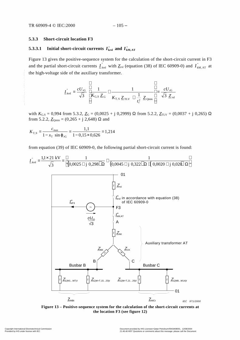
TR 60909-4 © IEC:2000 – 105 –
5.3.3 Short-circuit location F3
5.3.3.1 Initial short-circuit currents "ATkM,
"krsl and II
Figure 13 gives the positive-sequence system for the calculation of the short-circuit current in F3
and the partial short-circuit currents "krslI with Zrsl (equation (38) of IEC 60909-0) and " AT,kMI at
the high-voltage side of the auxiliary transformer.
rsl
rG
Qmin2r
TLVST,GSG,
rG"krsl
3111
3 Z
cU
Zt
ZKZK
cUI =
++=
with KG,S = 0,994 from 5.3.2, ZG = (0,0025 + j 0,2999) Ω from 5.2.2, ZTLV = (0,0037 + j 0,265) Ωfrom 5.2.2, ZQmin = (0,265 + j 2,648) Ω and
1,2140,6260,151
1,1
sin1 rGT
maxST, =
×−=
ϕ−=
x
cK
from equation (39) of IEC 60909-0, the following partial short-circuit current is found:
( ) ( ) ( )
Ω++Ω+
+Ω+
=×
=020,0j0020,0322,0j0045,0
1
298,0j0025,0
1
3
kV211,1"krslI
~ Zrsl
IkF3"
cUrG
√3
01
~
~
~ ~ ~ ~
~
01
Ikrsl in acordance with [1,(38)]"
IkM,AT"
F3
A
ZAK
ZBK ZCK
B CBusbar B
ZΣ(M1...M7)t ZΣ(M+T,15...20)t ZΣ(M+T,21...26)t ZΣ(M8...M14)t
ZMCtZMBt
Busbar C
Auxiliary transformer AT
Figure 13 – Positive-sequence system for the calculation of the short-circuit currents atthe location F3 (see figure 12)
in accordance with equation (38)of IEC 60909-0
Auxiliary transformer AT
tt t t
IEC 971/2000
Copyright International Electrotechnical Commission Provided by IHS under license with IEC
Document provided by IHS Licensee=Qatar Petroleum/5943408001, 12/08/200421:46:46 MST Questions or comments about this message: please call the DocumentPolicy Group at 303-397-2295.
--``,,,,,``,````,``,,,,`,```,``-`-`,,`,,`,`,,`---
– 106 – TR 60909-4 © CEI:2000
Les impédances avec indice t sont transférées du côté haute tension A du transformateurauxiliaire avec trAT = 21 kV/10,5 kV = 2,0.
( )( ) kA83,74kA;83,73j1,13
0,1592j0,00213
kV211,1 "krsl
"krsl =−=
+
×= II
Zrsl = (0,0021 + j 0,1592) Ω
L'addition de "kGI et "
kTI de 5.3.2 donnerait "kGI + "kTI = 44,74 kA + 46,79 kA = 91,53 kA, un
résultat d'environ 9,3 % supérieur à "krslI obtenu avec l’équation (38) de la CEI 60909-0.
NOTE Cette comparaison donne l'une des raisons pour lesquelles les résultats obtenus avec la méthode par super-
position ou un calcul transitoire peuvent être inférieurs à des résultats obtenus avec une simple addition de"kGI et "
kTI .
Le courant de court-circuit partiel "
AT,kMI à la figure 13 peut être obtenu à partir des résultats des
tableaux 8 et 9 pour les moteurs à basse et moyenne tensions. Les impédances à la figure 13sont:
ZΣ(M1...M7)t = (0,089 + j 0,777) Ω 2
kV5,10
kV21
= (0,356 + j 3,108) Ω
ZΣ (M+T,15...20)t = (0,980 + j 2,600) Ω 2
kV5,10
kV21
= (3,92 + j 10,40) Ω
ZMBt = (0,410 + j 2,420) Ω, voir figure 13
ZΣ (M8...M14)t = (0,138 + j 1,165) Ω 2
kV5,10
kV21
= (0,552 + j 4,660) Ω
ZΣ (M+T,21...26)t = ZΣ (M+T,15...20)t = (3,92 + j 10,40) Ω
ZMCt = (0,626 + j 3,260) Ω (voir figure 13)
Les impédances ZAK, ZBK et ZCK côté A sont déjà calculées en 5.2.3. Pour le calcul de "
AT,kMI
l'impédance ZM,AT est nécessaire:
( ) ( )MCtMBtCKBK
MCtCKMBtBKAK
"AT,M Z
ZZZZ
ZZZZZ
+++++
+= = (0,273 + j 2,081) Ω
( ) Ω+×==
081,2j273,03
kV211,1
3 AT,M
rG"AT,kM
Z
cUI = (0,827 – j 6,300) kA
"AT,kMI = 6,35 kA
Copyright International Electrotechnical Commission Provided by IHS under license with IEC
Document provided by IHS Licensee=Qatar Petroleum/5943408001, 12/08/200421:46:46 MST Questions or comments about this message: please call the DocumentPolicy Group at 303-397-2295.
--``,,,,,``,````,``,,,,`,```,``-`-`,,`,,`,`,,`---

TR 60909-4 © IEC:2000 – 107 –
Impedances with Index t are transferred to the high-voltage side A of the auxiliary transformerwith trAT = 21 kV/10,5 kV = 2,0.
( )( ) kA83,74kA;83,73j1,13
0,1592j0,00213
kV211,1 "krsl
"krsl =−=
+
×= II
Zrsl = (0,0021 + j 0,1592) Ω
The addition of "kGI and "
kTI from 5.3.2 would lead to "kGI + "kTI = 44,74 kA + 46,79 kA = 91,53 kA,
a result which is about 9,3 % higher than "krslI found with equation (38) of IEC 60909-0.
NOTE This comparison gives one of the reasons why results found with the superposition method or a transient
calculation may be smaller in comparison with a result found with a simple addition of "kGI and "
kTI .
The partial short-circuit current "
AT,kMI in figure 13 can be found from the results of the tables 8
and 9 for the low-voltage and medium-voltage motors. The impedances in figure 13 are:
ZΣ(M1...M7)t = (0,089 + j 0,777) Ω 2
kV5,10
kV21
= (0,356 + j 3,108) Ω
ZΣ (M+T,15...20)t = (0,980 + j 2,600) Ω 2
kV5,10
kV21
= (3,92 + j 10,40) Ω
ZMBt = (0,410 + j 2,420) Ω, see figure 13
ZΣ (M8...M14)t = (0,138 + j 1,165) Ω 2
kV5,10
kV21
= (0,552 + j 4,660) Ω
ZΣ (M+T,21...26)t = ZΣ (M+T,15...20)t = (3,92 + j 10,40) Ω
ZMCt = (0,626 + j 3,260) Ω (see figure 13)
The impedances ZAK, ZBK and ZCK referred to side A are calculated already in 5.2.3. For the
calculation of "
AT,kMI the impedance ZM,AT is needed:
( ) ( )MCtMBtCKBK
MCtCKMBtBKAK
"AT,M Z
ZZZZ
ZZZZZ
+++++
+= = (0,273 + j 2,081) Ω
( ) Ω+×==
081,2j273,03
kV211,1
3 AT,M
rG"AT,kM
Z
cUI = (0,827 – j 6,300) kA
"AT,kMI = 6,35 kA
Copyright International Electrotechnical Commission Provided by IHS under license with IEC
Document provided by IHS Licensee=Qatar Petroleum/5943408001, 12/08/200421:46:46 MST Questions or comments about this message: please call the DocumentPolicy Group at 303-397-2295.
--``,,,,,``,````,``,,,,`,```,``-`-`,,`,,`,`,,`---

– 108 – TR 60909-4 © CEI:2000
Ce courant de court-circuit partiel " AT,kMI = 6,35 kA est à considérer parce que son amplitude
atteint 7,5 % du courant "krslI = 83,74 kA.
Le courant de court-circuit total en F3 (voir la figure 13) atteint donc:
( ) kA05,90;kA03,90j96,1 "3kF
"AT,kM
"krst
"3kF =−=+= IIII
NOTE Dans le cas d'un court-circuit en F3 (figure 13) les tensions résiduelles entre phases au niveau des jeux debarres B est d'environ 4,1 kV, c'est-à-dire presque 40 % des tensions entre phases avant le court-circuit.
5.3.3.2 Courants de court-circuit de crête iprsl et ipM,AT
Le courant de court-circuit de crête iprsl peut être obtenu en utilisant les deux parties del’équation (38) de la CEI 60909-0:
iprsl = κG,S 2tZZK
cU
ZK
cU
minQTLVST,
rGST,
GSG,
rG
32
3 ++
iprsl = 1,86 ×× 2 44,74 kA + 1,94 ×× 2 39,0 kA = 224,7 kA
avec ;1,860,05 0,2995
0,0150SG,"
d
Gf =→==X
R (ZGf de 5.2.2)
et 1,940,019 0,342 0,0066
Im
Rerst
minQTLVST,
minQTLVST,
=→==+
+
t
t
ZZK
ZZK
NOTE Un calcul avec la méthode 20 Hz (4.3.1.2(c) de la CEI 60909-0), utilisant ZGf de 2.5.5 et l'impédance Zrsl(c)
d'après l’équation (38) de la CEI 60909-0) donne:
kA2,226kA73,83291,1"2
91,10334,0Hz50
Hz20
06376,0
00565,0
krslrslprsl
rslc
)c(rsl
)c(rsl
=××=κ=
=κ→=×Ω
Ω=×=
Ii
f
f
X
R
X
R
Le courant de court-circuit de crête ipM,AT peut être obtenu avec la méthode (b) (4.3.1.2(b) de laCEI 60909-0) mais sans le facteur 1,15, parce que les impédances correspondantes des moteurs àmoyenne tension ont un rapport R/X < 0,3 (4.3.1.2 de la CEI 60909-0).
ipM,AT = kA15,09kA6,3521,682 "ATkM,(b) =×=I
avec ( ) 1,680,131 2,081
0,273b
ATM,
ATM, =→==X
R
NOTE Un calcul avec la méthode 20 Hz donne pratiquement le même résultat dans ce cas (écart inférieur à 0,4 %).
Copyright International Electrotechnical Commission Provided by IHS under license with IEC
Document provided by IHS Licensee=Qatar Petroleum/5943408001, 12/08/200421:46:46 MST Questions or comments about this message: please call the DocumentPolicy Group at 303-397-2295.
--``,,,,,``,````,``,,,,`,```,``-`-`,,`,,`,`,,`---

TR 60909-4 © IEC:2000 – 109 –
This partial short-circuit current " AT,kMI = 6,35 kA is to be considered, because its magnitude
reaches 7,5 % of the current "krslI = 83,74 kA.
The total short-circuit current in F3 (see figure 13) therefore reaches:
( ) kA05,90;kA03,90j96,1 "3kF
"AT,kM
"krst
"3kF =−=+= IIII
NOTE In the case of a short circuit in F3 (figure 13) the residual line-to-line voltages at the busbars B isapproximately 4,1 kV, i.e. nearly 40 % of the line-to-line voltages before the short circuit.
5.3.3.2 Peak short-circuit currents iprsl and ipM,AT
The peak short-circuit current iprsl can be found using the two parts of equation (38) ofIEC 60909-0:
iprsl = κG,S 2tZZK
cU
ZK
cU
minQTLVST,
rGST,
GSG,
rG
32
3 ++
iprsl = 1,86 ×× 2 44,74 kA + 1,94 ×× 2 39,0 kA = 224,7 kA
with ;1,860,05 0,2995
0,0150SG,"
d
Gf =→==X
R (ZGf from clause 5.2.2)
and 1,940,019 0,342 0,0066
Im
Rerst
minQTLVST,
minQTLVST,
=→==+
+
t
t
ZZK
ZZK
NOTE A calculation with the 20 Hz method (4.3.1.2(c) of IEC 60909-0), using ZGf from 2.5.5 and the impedanceZrsl(c) according to equation (38) of IEC 60909-0) leads to:
kA2,226kA73,83291,1"2
91,10334,0Hz50
Hz20
06376,0
00565,0
krslrslprsl
rslc
)c(rsl
)c(rsl
=××=κ=
=κ→=×Ω
Ω=×=
Ii
f
f
X
R
X
R
The peak short-circuit current ipM,AT can be found with method (b) (4.3.1.2(b) of IEC 60909-0),but without the factor 1,15, because the relevant impedances of the medium-voltage motors havea ratio R/X < 0,3 (4.3.1.2 of IEC 60909-0).
ipM,AT = kA15,09kA6,3521,682 "ATkM,(b) =×=I
with ( ) 1,680,131 2,081
0,273b
ATM,
ATM, =→==X
R
NOTE A calculation with the 20 Hz method leads nearly to the same result in this case (deviation smaller than 0,4 %).
Copyright International Electrotechnical Commission Provided by IHS under license with IEC
Document provided by IHS Licensee=Qatar Petroleum/5943408001, 12/08/200421:46:46 MST Questions or comments about this message: please call the DocumentPolicy Group at 303-397-2295.
--``,,,,,``,````,``,,,,`,```,``-`-`,,`,,`,`,,`---
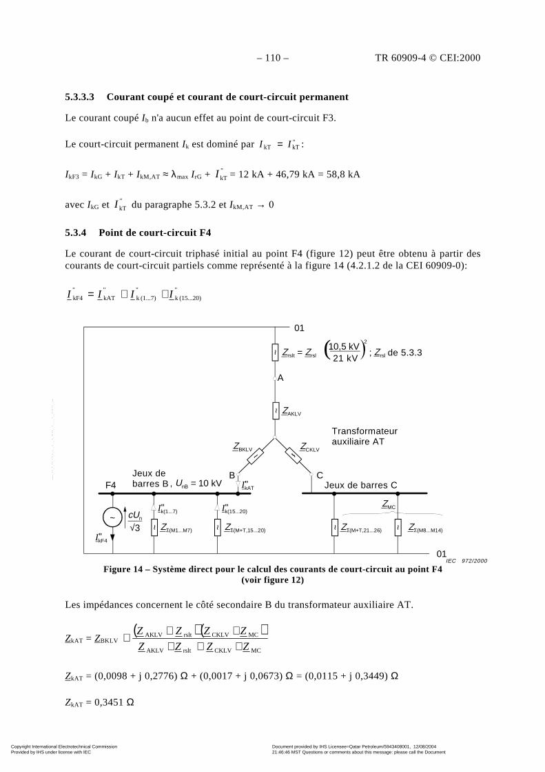
– 110 – TR 60909-4 © CEI:2000
5.3.3.3 Courant coupé et courant de court-circuit permanent
Le courant coupé Ib n'a aucun effet au point de court-circuit F3.
Le court-circuit permanent Ik est dominé par "kTkT II = :
IkF3 = IkG + IkT + IkM,AT ≈ λmax I rG + "I kT = 12 kA + 46,79 kA = 58,8 kA
avec IkG et "I kT du paragraphe 5.3.2 et IkM,AT → 0
5.3.4 Point de court-circuit F4
Le courant de court-circuit triphasé initial au point F4 (figure 12) peut être obtenu à partir descourants de court-circuit partiels comme représenté à la figure 14 (4.2.1.2 de la CEI 60909-0):
"(15...20)k
"(1...7)k
"kAT
"kF4 IIII ++=
Figure 14 – Système direct pour le calcul des courants de court-circuit au point F4(voir figure 12)
Les impédances concernent le côté secondaire B du transformateur auxiliaire AT.
ZkAT = ZBKLV ( ) ( )
MCCKLVrsltAKLV
MCCKLVrsltAKLV
ZZZZ
ZZZZ
++++++
ZkAT = (0,0098 + j 0,2776) Ω + (0,0017 + j 0,0673) Ω = (0,0115 + j 0,3449) Ω
ZkAT = 0,3451 Ω
IkF4"
cUn
√3
01
~
~ ~
~
01
F4
A
ZAKLV
ZBKLV ZCKLV
B CBusbar B, UnB = 10 kV
ZΣ(M1...M7) ZΣ(M+T,15...20)
Busbar C
~Ik(1...7)" Ik(15...20)"
~ ~ZΣ(M+T,21...26) ZΣ(M8...M14)
ZMC
~ Zrslt = Zrsl ; Zrsl from clouse 5.3.310,5 kV21kV( 2
Auxiliary transformer AT
IkAT"
Transformateurauxiliaire AT
Jeux de barres CJeux debarres B
de 5.3.3
IEC 972/2000
21 kV
Copyright International Electrotechnical Commission Provided by IHS under license with IEC
Document provided by IHS Licensee=Qatar Petroleum/5943408001, 12/08/200421:46:46 MST Questions or comments about this message: please call the DocumentPolicy Group at 303-397-2295.
--``,,,,,``,````,``,,,,`,```,``-`-`,,`,,`,`,,`---

TR 60909-4 © IEC:2000 – 111 –
5.3.3.3 Breaking current and steady-state short-circuit current
The breaking current Ib is of no interest at the short-circuit location F3.
The steady-state short-circuit Ik is dominated by "kTkT II = :
IkF3 = IkG + IkT + IkM,AT ≈ λmax I rG + "I kT = 12 kA + 46,79 kA = 58,8 kA
with IkG and "I kT from 5.3.2 and IkM,AT → 0
5.3.4 Short-circuit location F4
The initial three-phase short-circuit current at the location F4 (figure 12) can be found from thepartial short-circuit currents as shown in figure 14 (4.2.1.2 of IEC 60909-0):
"(15...20)k
"(1...7)k
"kAT
"kF4 IIII ++=
IkF4"
cUn
√3
01
~
~ ~
~
01
F4
A
ZAKLV
ZBKLV ZCKLV
B CBusbar B, UnB = 10 kV
ZΣ(M1...M7) ZΣ(M+T,15...20)
Busbar C
~Ik(1...7)" Ik(15...20)"
~ ~ZΣ(M+T,21...26) ZΣ(M8...M14)
ZMC
~ Zrslt = Zrsl ; Zrsl from clouse 5.3.310,5 kV21kV( 2
Auxiliary transformer AT
IkAT"
Figure 14 – Positive-sequence system for the calculation of the short-circuit currents atthe location F4 (see figure 12)
Impedances are referred to the secondary side B of the auxiliary transformer AT.
ZkAT = ZBKLV ( ) ( )
MCCKLVrsltAKLV
MCCKLVrsltAKLV
ZZZZ
ZZZZ
++++++
ZkAT = (0,0098 + j 0,2776) Ω + (0,0017 + j 0,0673) Ω = (0,0115 + j 0,3449) Ω
ZkAT = 0,3451 Ω
from 5.3.3
IEC 972/2000
21 kV
Copyright International Electrotechnical Commission Provided by IHS under license with IEC
Document provided by IHS Licensee=Qatar Petroleum/5943408001, 12/08/200421:46:46 MST Questions or comments about this message: please call the DocumentPolicy Group at 303-397-2295.
--``,,,,,``,````,``,,,,`,```,``-`-`,,`,,`,`,,`---
– 112 – TR 60909-4 © CEI:2000
avec ZAKLV = ZAK/ 2rt ; ZBKLV = ZCKLV = ZBK/ 2
rt ; ZAK ZBK de 5.2.3,
ZMC = ZMCt/2rt ; ZMCt de 5.3.3,
Zrsl de 5.3.3 (voir la figure 13)
( ) 0,3449j0,01153
kV101,1
3 kAT
n"kAT
+×
==Z
cUI = (0,613 – j 18,393) kA
Des tableaux 8 et 9:
( ) 0,777j0,0893
kV101,1
3 (M1...M7)
n(1...7)k
+
×==
∑Z
cUI " = (0,924 – j 8,068) kA
( ) 2,600j0,9803
kV101,1
3 15...20)T,(M
n")20...15(k
+×
==∑ +Z
cUI = (0,806 – j 2,139) kA
( ) kA28,70kA;28,60j2,343 "kF4
"kF4 =−= II
NOTE Si l'on néglige l'influence des moteurs alimentés par le jeu de barres C sur le courant de court-circuit en F4,on obtient:
ZkAT ≈ ZBKLV + ZAKLV + Zrslt = (0,011 + j 0,349) Ω"
kATI ≈ (0,573 – j 18,179) kA
( ) kA28,48;kA28,386j2,303 "kF4
"
kF4 =−= II
L'influence des moteurs alimentés par le jeu de barres C est faible, inférieure à 1 % du courant "
kF4I . Elle peut dans
ce cas être négligée.
Les courants de court-circuit de crête sont obtenus par la méthode 6 (4.3.1.2(b) de la CEI 60909-0)
sans le facteur 1,15 parce que R/X < 0,3 dans les branches qui sont concernées pour "kATI et pour
les moteurs asynchrones à moyenne tension.
kA73,79kA2,2921,34kA8,1221,72kA18,4021,91
222
pF4
"(15...20)k(15...20)
"(1...7)k(1...7)
"kATATpF4
=××+××+××=
++=
i
IIIi
Si le courant de court-circuit partiel "kATI est transféré au côté haute tension du transformateur
auxiliaire, on peut voir que "
tkATI = 9,2 kA est inférieur à 2 I rG = 2 × 6,87 kA, de telle sorte que
le court-circuit en F4 est un court-circuit éloigné d'un alternateur.
IbF4 = IbAT + Ib(1...7) + Ib(15...20) = 22,8 kA
Copyright International Electrotechnical Commission Provided by IHS under license with IEC
Document provided by IHS Licensee=Qatar Petroleum/5943408001, 12/08/200421:46:46 MST Questions or comments about this message: please call the DocumentPolicy Group at 303-397-2295.
--``,,,,,``,````,``,,,,`,```,``-`-`,,`,,`,`,,`---
TR 60909-4 © IEC:2000 – 113 –
with ZAKLV = ZAK/ 2rt ; ZBKLV = ZCKLV = ZBK/ 2
rt ; ZAK ZBK from 5.2.3,
ZMC = ZMCt/2rt ; ZMCt from 5.3.3,
Zrsl from 5.3.3 (see figure 13)
( ) 0,3449j0,01153
kV101,1
3 kAT
n"kAT
+×
==Z
cUI = (0,613 – j 18,393) kA
From table 8 and 9:
( ) 0,777j0,0893
kV101,1
3 (M1...M7)
n(1...7)k
+
×==
∑Z
cUI " = (0,924 – j 8,068) kA
( ) 2,600j0,9803
kV101,1
3 15...20)T,(M
n")20...15(k
+×
==∑ +Z
cUI = (0,806 – j 2,139) kA
( ) kA28,70kA;28,60j2,343 "kF4
"kF4 =−= II
NOTE Neglecting the influence of the motors fed from busbar C to the short-circuit current in F4 leads to:
ZkAT ≈ ZBKLV + ZAKLV + Zrslt = (0,011 + j 0,349) Ω"
kATI ≈ (0,573 – j 18,179) kA
( ) kA28,48;kA28,386j2,303 "kF4
"
kF4 =−= II
The influence of the motors fed from busbar C is small, smaller than 1 % to the current "
kF4I . They may be neglected
in this case.
The peak short-circuit currents are found with method 6 (4.3.1.2(b) of IEC 60909-0) without the
factor 1,15 because R/X < 0,3 in branches which are relevant for "kATI and for the medium-
voltage asynchronous motors.
kA73,79kA2,2921,34kA8,1221,72kA18,4021,91
222
pF4
"(15...20)k(15...20)
"(1...7)k(1...7)
"kATATpF4
=××+××+××=
++=
i
IIIi
If the partial short-circuit current "kATI is transferred to the high-voltage side of the auxiliary
transformer, it can be seen that "
tkATI = 9,2 kA is smaller than 2I rG = 2 × 6,87 kA, so that the
short circuit in F4 is a far-from-generator short circuit.
IbF4 = IbAT + Ib(1...7) + Ib(15...20) = 22,8 kA
Copyright International Electrotechnical Commission Provided by IHS under license with IEC
Document provided by IHS Licensee=Qatar Petroleum/5943408001, 12/08/200421:46:46 MST Questions or comments about this message: please call the DocumentPolicy Group at 303-397-2295.
--``,,,,,``,````,``,,,,`,```,``-`-`,,`,,`,`,,`---

– 114 – TR 60909-4 © CEI:2000
avec "kATbAT II = =18,40 kA
)7...1(bI = ∑=
7
1i
"kMiii Iq = 4,04 kA (voir le tableau 9)
)20...15(bI = µ × q × "
)20...15(kI = 0,74 ×⋅ 0,21 × 2,29 kA = 0,36 kA
(µ = 0,74 de tmin = 0,1 s et "kMI /I rM = 5,5 et q = 0,21 de tmin = 0,1 s et PrM/p = 0,05 MW;
")20...15(kI = 2,29 kA du tableau 8)
5.3.5 Point de court-circuit F5
Le courant de court-circuit symétrique initial au point de court-circuit F5 peut être calculé avecle système direct donné à la figure 15.
"kM20
"kT20
"kF5 III +=
Pour le calcul du courant de court-circuit partiel "
20kTI les impédances suivantes sont utilisées(voir la figure 15):
ZkATt = ZkAT220r
1
t = (0,0115 + j 0,3449) Ω
2
kV10
kV42,0
= (0,0203 + j 0,6084) mΩ
Figure 15 – Système direct pour le calcul des courants de court-circuit au point F5(voir la figure 12). Les impédances concernent le côté basse tension
du transformateur T20 (tr20 = 10 kV/0,42 kV)
~
IkF5"
cUnD
√3
01
~
01
~~
~ ~
Busbar B, UnB = 10 kV
ZkATt = ZkAT/tr202
ZΣ (M+T,15...19)tZΣ (M1...M7)t
ZT20LVK
ZM20
IkM20"
D
IkT20"
F5
UnD = 400 V
Jeu de barres B
IEC 973/2000
Copyright International Electrotechnical Commission Provided by IHS under license with IEC
Document provided by IHS Licensee=Qatar Petroleum/5943408001, 12/08/200421:46:46 MST Questions or comments about this message: please call the DocumentPolicy Group at 303-397-2295.
--``,,,,,``,````,``,,,,`,```,``-`-`,,`,,`,`,,`---
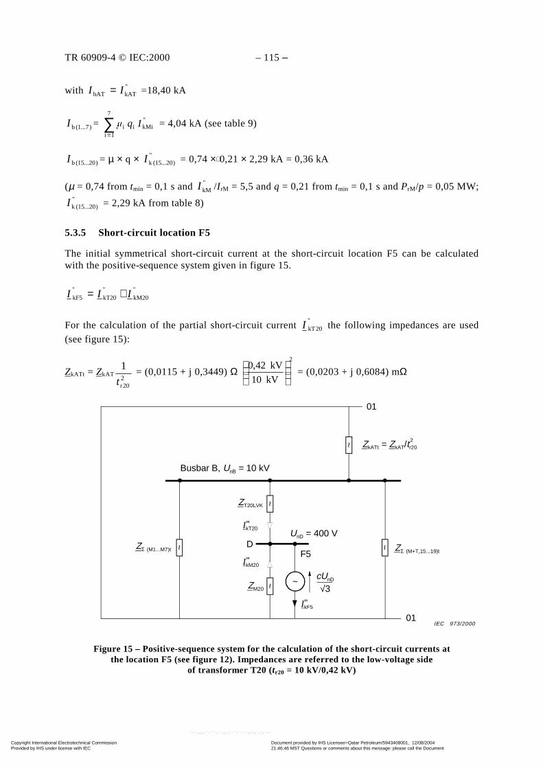
TR 60909-4 © IEC:2000 – 115 –
with "kATbAT II = =18,40 kA
)7...1(bI = ∑=
7
1i
"kMiii Iq = 4,04 kA (see table 9)
)20...15(bI = µ × q × "
)20...15(kI = 0,74 ×⋅ 0,21 × 2,29 kA = 0,36 kA
(µ = 0,74 from tmin = 0,1 s and "kMI /I rM = 5,5 and q = 0,21 from tmin = 0,1 s and PrM/p = 0,05 MW;
")20...15(kI = 2,29 kA from table 8)
5.3.5 Short-circuit location F5
The initial symmetrical short-circuit current at the short-circuit location F5 can be calculatedwith the positive-sequence system given in figure 15.
"kM20
"kT20
"kF5 III +=
For the calculation of the partial short-circuit current "
20kTI the following impedances are used(see figure 15):
ZkATt = ZkAT220r
1
t = (0,0115 + j 0,3449) Ω
2
kV10
kV42,0
= (0,0203 + j 0,6084) mΩ
Figure 15 – Positive-sequence system for the calculation of the short-circuit currents atthe location F5 (see figure 12). Impedances are referred to the low-voltage side
of transformer T20 (tr20 = 10 kV/0,42 kV)
~
IkF5"
cUnD
√3
01
~
01
~~
~ ~
Busbar B, UnB = 10 kV
ZkATt = ZkAT/tr202
ZΣ (M+T,15...19)tZΣ (M1...M7)t
ZT20LVK
ZM20
IkM20"
D
IkT20"
F5
UnD = 400 V
IEC 973/2000
Copyright International Electrotechnical Commission Provided by IHS under license with IEC
Document provided by IHS Licensee=Qatar Petroleum/5943408001, 12/08/200421:46:46 MST Questions or comments about this message: please call the DocumentPolicy Group at 303-397-2295.
--``,,,,,``,````,``,,,,`,```,``-`-`,,`,,`,`,,`---
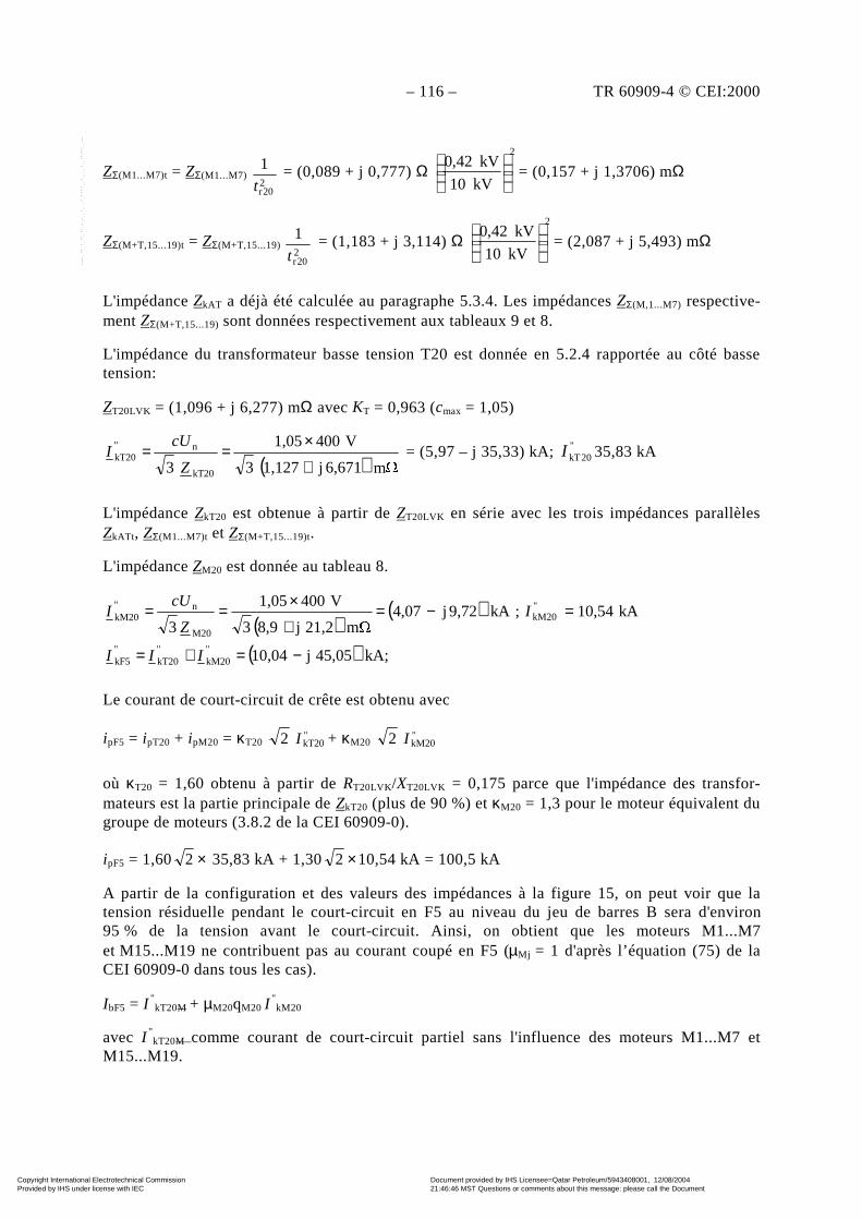
– 116 – TR 60909-4 © CEI:2000
ZΣ(M1...M7)t = ZΣ(M1...M7) 220r
1t
= (0,089 + j 0,777) Ω 2
kV10
kV42,0
= (0,157 + j 1,3706) mΩ
ZΣ(M+T,15...19)t = ZΣ(M+T,15...19) 220r
1
t = (1,183 + j 3,114) Ω
2
kV10
kV42,0
= (2,087 + j 5,493) mΩ
L'impédance ZkAT a déjà été calculée au paragraphe 5.3.4. Les impédances ZΣ(M,1...M7) respective-ment ZΣ(M+T,15...19) sont données respectivement aux tableaux 9 et 8.
L'impédance du transformateur basse tension T20 est donnée en 5.2.4 rapportée au côté bassetension:
ZT20LVK = (1,096 + j 6,277) mΩ avec KT = 0,963 (cmax = 1,05)
( ) m 6,671j1,1273
V4001,05
3 kT20
n"kT20
+
×==
Z
cUI = (5,97 – j 35,33) kA; "
20kTI 35,83 kA
L'impédance ZkT20 est obtenue à partir de ZT20LVK en série avec les trois impédances parallèlesZkATt, ZΣ(M1...M7)t et ZΣ(M+T,15...19)t.
L'impédance ZM20 est donnée au tableau 8.
( )( )
( ) kA46,16kA;45,05j10,04
kA10,54;kA9,72j4,07m 21,2j8,93
V4001,05
3"kF5
"kM20
"kT20
"kF5
"kM20
M20
n"kM20
=−=+=
=−=+
×==
IIII
IZ
cUI
Le courant de court-circuit de crête est obtenu avec
ipF5 = ipT20 + ipM20 = κT20 "kT202 I + κM20 "
kM202 I
où κT20 = 1,60 obtenu à partir de RT20LVK/XT20LVK = 0,175 parce que l'impédance des transfor-mateurs est la partie principale de ZkT20 (plus de 90 %) et κM20 = 1,3 pour le moteur équivalent dugroupe de moteurs (3.8.2 de la CEI 60909-0).
ipF5 = 1,60 ×2 35,83 kA + 1,30 ×2 10,54 kA = 100,5 kA
A partir de la configuration et des valeurs des impédances à la figure 15, on peut voir que latension résiduelle pendant le court-circuit en F5 au niveau du jeu de barres B sera d'environ95 % de la tension avant le court-circuit. Ainsi, on obtient que les moteurs M1...M7et M15...M19 ne contribuent pas au courant coupé en F5 (µMj = 1 d'après l’équation (75) de laCEI 60909-0 dans tous les cas).
IbF5 = I "kT20M + µM20qM20 I
"kM20
avec I "kT20M comme courant de court-circuit partiel sans l'influence des moteurs M1...M7 et
M15...M19.
Copyright International Electrotechnical Commission Provided by IHS under license with IEC
Document provided by IHS Licensee=Qatar Petroleum/5943408001, 12/08/200421:46:46 MST Questions or comments about this message: please call the DocumentPolicy Group at 303-397-2295.
--``,,,,,``,````,``,,,,`,```,``-`-`,,`,,`,`,,`---
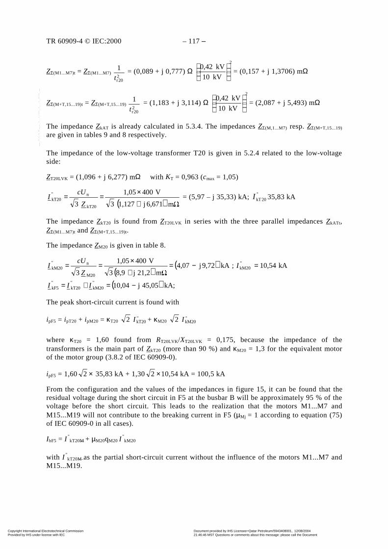
TR 60909-4 © IEC:2000 – 117 –
ZΣ(M1...M7)t = ZΣ(M1...M7) 220r
1t
= (0,089 + j 0,777) Ω 2
kV10
kV42,0
= (0,157 + j 1,3706) mΩ
ZΣ(M+T,15...19)t = ZΣ(M+T,15...19) 220r
1t
= (1,183 + j 3,114) Ω 2
kV10
kV42,0
= (2,087 + j 5,493) mΩ
The impedance ZkAT is already calculated in 5.3.4. The impedances ZΣ(M,1...M7) resp. ZΣ(M+T,15...19)
are given in tables 9 and 8 respectively.
The impedance of the low-voltage transformer T20 is given in 5.2.4 related to the low-voltageside:
ZT20LVK = (1,096 + j 6,277) mΩ with KT = 0,963 (cmax = 1,05)
( ) m 6,671j1,1273
V4001,05
3 kT20
n"kT20
+
×==
Z
cUI = (5,97 – j 35,33) kA; "
20kTI 35,83 kA
The impedance ZkT20 is found from ZT20LVK in series with the three parallel impedances ZkATt,ZΣ(M1...M7)t and ZΣ(M+T,15...19)t.
The impedance ZM20 is given in table 8.
( )( )
( ) kA46,16kA;45,05j10,04
kA10,54;kA9,72j4,07m 21,2j8,93
V4001,05
3"kF5
"kM20
"kT20
"kF5
"kM20
M20
n"kM20
=−=+=
=−=+
×==
IIII
IZ
cUI
The peak short-circuit current is found with
ipF5 = ipT20 + ipM20 = κT20 "kT202 I + κM20 "
kM202 I
where κT20 = 1,60 found from RT20LVK/XT20LVK = 0,175, because the impedance of thetransformers is the main part of ZkT20 (more than 90 %) and κM20 = 1,3 for the equivalent motorof the motor group (3.8.2 of IEC 60909-0).
ipF5 = 1,60 ×2 35,83 kA + 1,30 ×2 10,54 kA = 100,5 kA
From the configuration and the values of the impedances in figure 15, it can be found that theresidual voltage during the short circuit in F5 at the busbar B will be approximately 95 % of thevoltage before the short circuit. This leads to the realization that the motors M1...M7 andM15...M19 will not contribute to the breaking current in F5 (µMj = 1 according to equation (75)of IEC 60909-0 in all cases).
IbF5 = I "kT20M + µM20qM20 I
"kM20
with I "kT20M as the partial short-circuit current without the influence of the motors M1...M7 and
M15...M19.
Copyright International Electrotechnical Commission Provided by IHS under license with IEC
Document provided by IHS Licensee=Qatar Petroleum/5943408001, 12/08/200421:46:46 MST Questions or comments about this message: please call the DocumentPolicy Group at 303-397-2295.
--``,,,,,``,````,``,,,,`,```,``-`-`,,`,,`,`,,`---
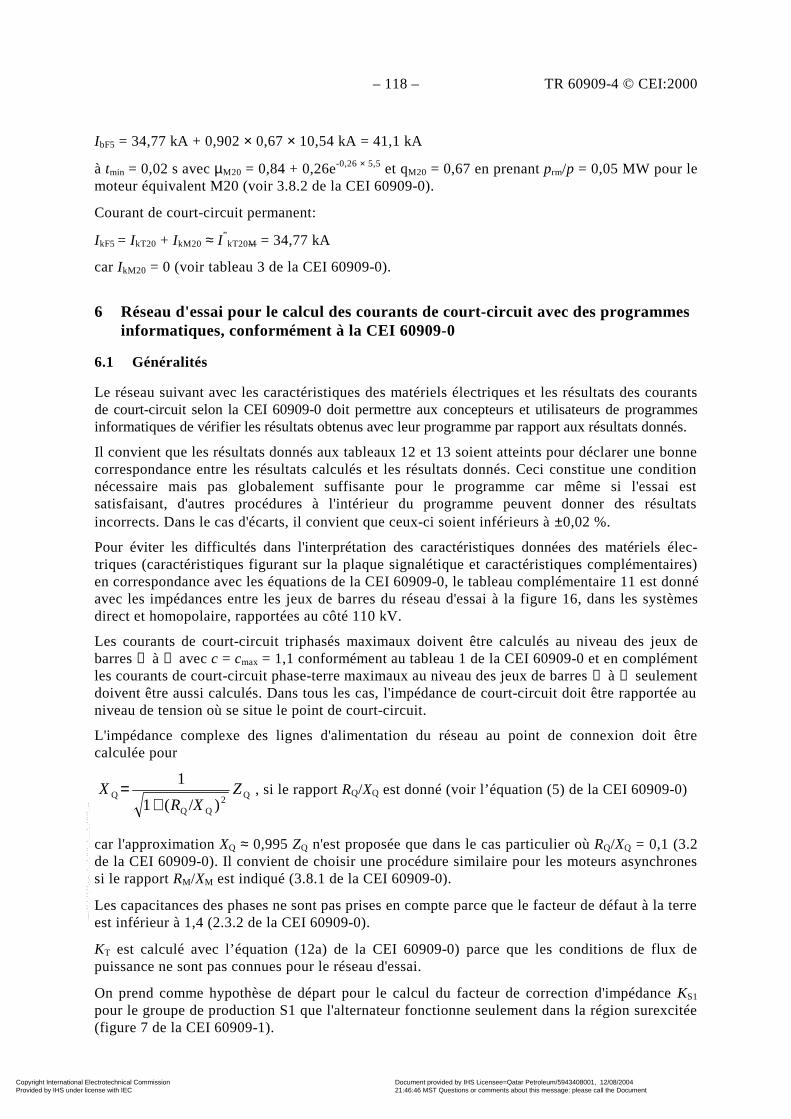
– 118 – TR 60909-4 © CEI:2000
IbF5 = 34,77 kA + 0,902 × 0,67 × 10,54 kA = 41,1 kA
à tmin = 0,02 s avec µM20 = 0,84 + 0,26e-0,26 × 5,5 et qM20 = 0,67 en prenant prm/p = 0,05 MW pour lemoteur équivalent M20 (voir 3.8.2 de la CEI 60909-0).
Courant de court-circuit permanent:
IkF5 = IkT20 + IkM20 ≈ I ”kT20M = 34,77 kA
car IkM20 = 0 (voir tableau 3 de la CEI 60909-0).
6 Réseau d'essai pour le calcul des courants de court-circuit avec des programmesinformatiques, conformément à la CEI 60909-0
6.1 Généralités
Le réseau suivant avec les caractéristiques des matériels électriques et les résultats des courantsde court-circuit selon la CEI 60909-0 doit permettre aux concepteurs et utilisateurs de programmesinformatiques de vérifier les résultats obtenus avec leur programme par rapport aux résultats donnés.
Il convient que les résultats donnés aux tableaux 12 et 13 soient atteints pour déclarer une bonnecorrespondance entre les résultats calculés et les résultats donnés. Ceci constitue une conditionnécessaire mais pas globalement suffisante pour le programme car même si l'essai estsatisfaisant, d'autres procédures à l'intérieur du programme peuvent donner des résultatsincorrects. Dans le cas d'écarts, il convient que ceux-ci soient inférieurs à ±0,02 %.
Pour éviter les difficultés dans l'interprétation des caractéristiques données des matériels élec-triques (caractéristiques figurant sur la plaque signalétique et caractéristiques complémentaires)en correspondance avec les équations de la CEI 60909-0, le tableau complémentaire 11 est donnéavec les impédances entre les jeux de barres du réseau d'essai à la figure 16, dans les systèmesdirect et homopolaire, rapportées au côté 110 kV.
Les courants de court-circuit triphasés maximaux doivent être calculés au niveau des jeux debarres ➀ à ➇ avec c = cmax = 1,1 conformément au tableau 1 de la CEI 60909-0 et en complémentles courants de court-circuit phase-terre maximaux au niveau des jeux de barres ➁ à ➄ seulementdoivent être aussi calculés. Dans tous les cas, l'impédance de court-circuit doit être rapportée auniveau de tension où se situe le point de court-circuit.
L'impédance complexe des lignes d'alimentation du réseau au point de connexion doit êtrecalculée pour
Q2QQ
Q)/(1
1Z
XRX
+= , si le rapport RQ/XQ est donné (voir l’équation (5) de la CEI 60909-0)
car l'approximation XQ ≈ 0,995 ZQ n'est proposée que dans le cas particulier où RQ/XQ = 0,1 (3.2de la CEI 60909-0). Il convient de choisir une procédure similaire pour les moteurs asynchronessi le rapport RM/XM est indiqué (3.8.1 de la CEI 60909-0).
Les capacitances des phases ne sont pas prises en compte parce que le facteur de défaut à la terreest inférieur à 1,4 (2.3.2 de la CEI 60909-0).
KT est calculé avec l’équation (12a) de la CEI 60909-0) parce que les conditions de flux depuissance ne sont pas connues pour le réseau d'essai.
On prend comme hypothèse de départ pour le calcul du facteur de correction d'impédance KS1
pour le groupe de production S1 que l'alternateur fonctionne seulement dans la région surexcitée(figure 7 de la CEI 60909-1).
Copyright International Electrotechnical Commission Provided by IHS under license with IEC
Document provided by IHS Licensee=Qatar Petroleum/5943408001, 12/08/200421:46:46 MST Questions or comments about this message: please call the DocumentPolicy Group at 303-397-2295.
--``,,,,,``,````,``,,,,`,```,``-`-`,,`,,`,`,,`---
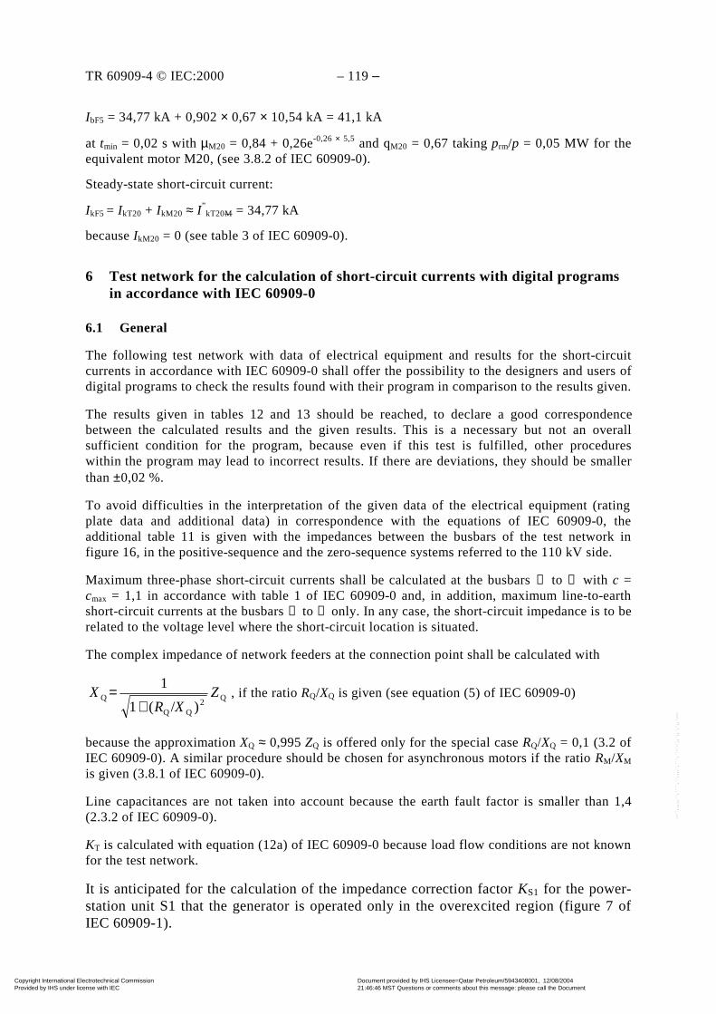
TR 60909-4 © IEC:2000 – 119 –
IbF5 = 34,77 kA + 0,902 × 0,67 × 10,54 kA = 41,1 kA
at tmin = 0,02 s with µM20 = 0,84 + 0,26e-0,26 × 5,5 and qM20 = 0,67 taking prm/p = 0,05 MW for theequivalent motor M20, (see 3.8.2 of IEC 60909-0).
Steady-state short-circuit current:
IkF5 = IkT20 + IkM20 ≈ I ”kT20M = 34,77 kA
because IkM20 = 0 (see table 3 of IEC 60909-0).
6 Test network for the calculation of short-circuit currents with digital programsin accordance with IEC 60909-0
6.1 General
The following test network with data of electrical equipment and results for the short-circuitcurrents in accordance with IEC 60909-0 shall offer the possibility to the designers and users ofdigital programs to check the results found with their program in comparison to the results given.
The results given in tables 12 and 13 should be reached, to declare a good correspondencebetween the calculated results and the given results. This is a necessary but not an overallsufficient condition for the program, because even if this test is fulfilled, other procedureswithin the program may lead to incorrect results. If there are deviations, they should be smallerthan ±0,02 %.
To avoid difficulties in the interpretation of the given data of the electrical equipment (ratingplate data and additional data) in correspondence with the equations of IEC 60909-0, theadditional table 11 is given with the impedances between the busbars of the test network infigure 16, in the positive-sequence and the zero-sequence systems referred to the 110 kV side.
Maximum three-phase short-circuit currents shall be calculated at the busbars ➀ to ➇ with c =cmax = 1,1 in accordance with table 1 of IEC 60909-0 and, in addition, maximum line-to-earthshort-circuit currents at the busbars ➁ to ➄ only. In any case, the short-circuit impedance is to berelated to the voltage level where the short-circuit location is situated.
The complex impedance of network feeders at the connection point shall be calculated with
Q2QQ
Q)/(1
1Z
XRX
+= , if the ratio RQ/XQ is given (see equation (5) of IEC 60909-0)
because the approximation XQ ≈ 0,995 ZQ is offered only for the special case RQ/XQ = 0,1 (3.2 ofIEC 60909-0). A similar procedure should be chosen for asynchronous motors if the ratio RM/XM
is given (3.8.1 of IEC 60909-0).
Line capacitances are not taken into account because the earth fault factor is smaller than 1,4(2.3.2 of IEC 60909-0).
KT is calculated with equation (12a) of IEC 60909-0 because load flow conditions are not knownfor the test network.
It is anticipated for the calculation of the impedance correction factor KS1 for the power-station unit S1 that the generator is operated only in the overexcited region (figure 7 ofIEC 60909-1).
Copyright International Electrotechnical Commission Provided by IHS under license with IEC
Document provided by IHS Licensee=Qatar Petroleum/5943408001, 12/08/200421:46:46 MST Questions or comments about this message: please call the DocumentPolicy Group at 303-397-2295.
--``,,,,,``,````,``,,,,`,```,``-`-`,,`,,`,`,,`---
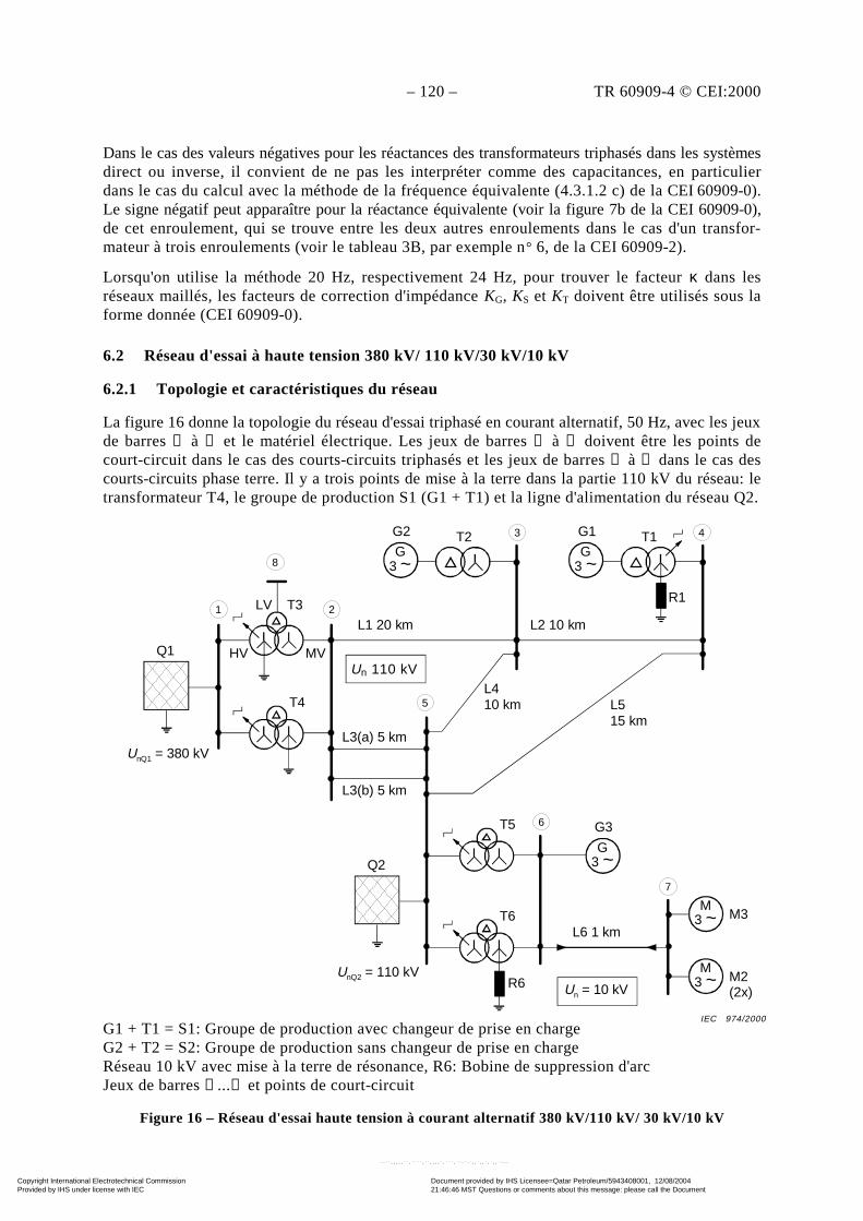
– 120 – TR 60909-4 © CEI:2000
Dans le cas des valeurs négatives pour les réactances des transformateurs triphasés dans les systèmesdirect ou inverse, il convient de ne pas les interpréter comme des capacitances, en particulierdans le cas du calcul avec la méthode de la fréquence équivalente (4.3.1.2 c) de la CEI 60909-0).Le signe négatif peut apparaître pour la réactance équivalente (voir la figure 7b de la CEI 60909-0),de cet enroulement, qui se trouve entre les deux autres enroulements dans le cas d'un transfor-mateur à trois enroulements (voir le tableau 3B, par exemple n° 6, de la CEI 60909-2).
Lorsqu'on utilise la méthode 20 Hz, respectivement 24 Hz, pour trouver le facteur κ dans lesréseaux maillés, les facteurs de correction d'impédance KG, KS et KT doivent être utilisés sous laforme donnée (CEI 60909-0).
6.2 Réseau d'essai à haute tension 380 kV/ 110 kV/30 kV/10 kV
6.2.1 Topologie et caractéristiques du réseau
La figure 16 donne la topologie du réseau d'essai triphasé en courant alternatif, 50 Hz, avec les jeuxde barres ➀ à ➇ et le matériel électrique. Les jeux de barres ➀ à ➇ doivent être les points decourt-circuit dans le cas des courts-circuits triphasés et les jeux de barres ➁ à ➄ dans le cas descourts-circuits phase terre. Il y a trois points de mise à la terre dans la partie 110 kV du réseau: letransformateur T4, le groupe de production S1 (G1 + T1) et la ligne d'alimentation du réseau Q2.
G1 + T1 = S1: Groupe de production avec changeur de prise en chargeG2 + T2 = S2: Groupe de production sans changeur de prise en chargeRéseau 10 kV avec mise à la terre de résonance, R6: Bobine de suppression d'arcJeux de barres ➀...➇ et points de court-circuit
Figure 16 – Réseau d'essai haute tension à courant alternatif 380 kV/110 kV/ 30 kV/10 kV
G3 ~
T2
UnQ1 = 380 kV
G2
G3 ~
T1G13 4
8
2
5
1 LV T3
HV MVQ1
T4
T6
R6UnQ2 = 110 kV
Q2
T5
G3 ~
G36
Un 110 kV
L1 20 km L2 10 km
R1
L3(a) 5 km
L3(b) 5 km
L4 10 km L5
15 km
7
M3 ~ M3
M3 ~ M2
(2x)Un = 10 kV
L6 1 km
IEC 974/2000
Un 110 kV
Copyright International Electrotechnical Commission Provided by IHS under license with IEC
Document provided by IHS Licensee=Qatar Petroleum/5943408001, 12/08/200421:46:46 MST Questions or comments about this message: please call the DocumentPolicy Group at 303-397-2295.
--``,,,,,``,````,``,,,,`,```,``-`-`,,`,,`,`,,`---
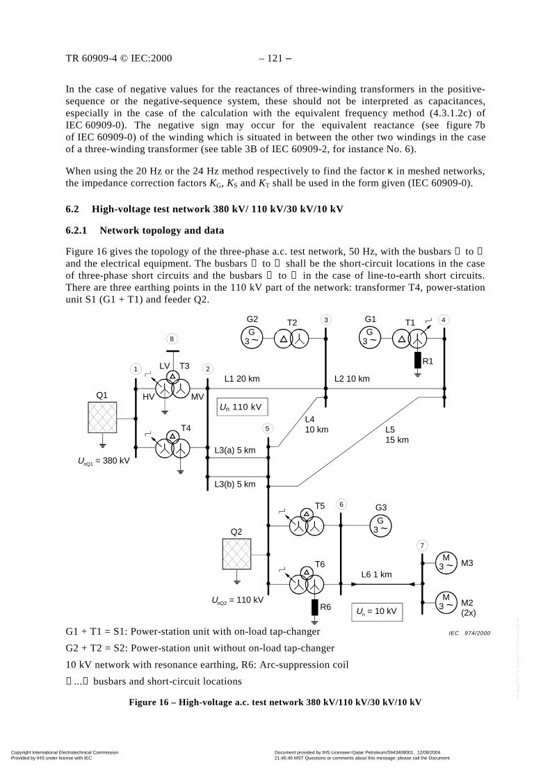
TR 60909-4 © IEC:2000 – 121 –
In the case of negative values for the reactances of three-winding transformers in the positive-sequence or the negative-sequence system, these should not be interpreted as capacitances,especially in the case of the calculation with the equivalent frequency method (4.3.1.2c) ofIEC 60909-0). The negative sign may occur for the equivalent reactance (see figure 7bof IEC 60909-0) of the winding which is situated in between the other two windings in the caseof a three-winding transformer (see table 3B of IEC 60909-2, for instance No. 6).
When using the 20 Hz or the 24 Hz method respectively to find the factor κ in meshed networks,the impedance correction factors KG, KS and KT shall be used in the form given (IEC 60909-0).
6.2 High-voltage test network 380 kV/ 110 kV/30 kV/10 kV
6.2.1 Network topology and data
Figure 16 gives the topology of the three-phase a.c. test network, 50 Hz, with the busbars ➀ to ➇and the electrical equipment. The busbars ➀ to ➇ shall be the short-circuit locations in the caseof three-phase short circuits and the busbars ➁ to ➄ in the case of line-to-earth short circuits.There are three earthing points in the 110 kV part of the network: transformer T4, power-stationunit S1 (G1 + T1) and feeder Q2.
G1 + T1 = S1: Power-station unit with on-load tap-changer
G2 + T2 = S2: Power-station unit without on-load tap-changer
10 kV network with resonance earthing, R6: Arc-suppression coil
➀...➇ busbars and short-circuit locations
Figure 16 – High-voltage a.c. test network 380 kV/110 kV/30 kV/10 kV
G3 ~
T2
UnQ1 = 380 kV
G2
G3 ~
T1G13 4
8
2
5
1 LV T3
HV MVQ1
T4
T6
R6UnQ2 = 110 kV
Q2
T5
G3 ~
G36
Un 110 kV
L1 20 km L2 10 km
R1
L3(a) 5 km
L3(b) 5 km
L4 10 km L5
15 km
7
M3 ~ M3
M3 ~ M2
(2x)Un = 10 kV
L6 1 km
IEC 974/2000
Un 110 kV
Copyright International Electrotechnical Commission Provided by IHS under license with IEC
Document provided by IHS Licensee=Qatar Petroleum/5943408001, 12/08/200421:46:46 MST Questions or comments about this message: please call the DocumentPolicy Group at 303-397-2295.
--``,,,,,``,````,``,,,,`,```,``-`-`,,`,,`,`,,`---

– 122 – TR 60909-4 © CEI:2000
Caractéristiques du matériel électrique:
Lignes d'alimentation du réseau
Q1: UnQ = 380 kV; "maxkQI = 38 kA (cmax = 1,1); RQ/XQ = 0,1; X(0)Q/XQ = 3;
R(0)Q/X(0)Q = 0,15.
Q2: UnQ = 110 kV; "maxkQI = 16 kA (cmax = 1,1); RQ/XQ = 0,1; X(0)Q/XQ = 3,3;
R(0)Q/X(0)Q = 0,2.
Groupes de production
S1 UrG = 21 kV; SrG = 150 MVA; "dx = 0,14 p.u.; xdsat = 1,8 p.u.; cosϕrG = 0,85; RG =
0,002 Ω (fonctionne uniquement dans la région surexcitée)
UrTHV/UrTLV = 115 kV/21 kV; SrT = 150 MVA; ukr = 16 %; uRr = 0,5 %; YNd5 avecchangeur de prise en charge pT = ±12 %; X(0)T/XT = 0,95; R(0)T/RT = 1,0.
S2: UrG = 10,5 kV; SrG = 100 MVA; pG = ±7,5 %; "dx = 0,16 p.u.; xdsat = 2,0 p.u.; cosϕrG =
0,9; RG = 0,005 Ω
UrTHV/UrTLV = 120 kV/10,5 kV; SrT = 100 MVA; ukr = 12 %; uRr = 0,5 %; YNd5 sanschangeur de prises ou prises à vide.
X(0)T/XT = 1,0; R(0)T/RT = 1,0.
Alternateur
G3: UrG = 10,5 kV; SrG = 10 MVA; pG = ±5% (pour le calcul une valeur constante UG = UrG est
prise comme hypothèse); "dx = 0,1 p.u.; xdsat = 1,8 p.u.; cosϕrG = 0,8; RG = 0,018 Ω
Transformateurs réseau
T3 = T4: Transformateurs réseau à trois enroulements YNyn,d5 avec changeur de prise encharge du côté haute tension, pT = ±16 %. Mise à la terre du neutre: T3 du côté hautetension, T4 du côté moyenne tension.
UrTHV = 400 kV; UrTMV = 120 kV; UrTLV = 30 kV;
SrTHV = 350 MVA; SrTMV = 350 MVA; SrTLV = 50 MVA;
ukrHVMV = 21 %; ukrHVLV = 10 %; ukrMVLV = 7 %;
uRrHVMV = 0,26 %; uRrHVLV = 0,16 %; uRrMVLV = 0,16 %;
X(0)TMV/XTMVHV = 2,1; R(0)TMV/RTMVHV = 1,0 (voir 2.2).
T5 = T6: Transformateur réseau à trois enroulements YNyn,d5, traité ici comme untransformateur à deux enroulements, c'est-à-dire ukr = ukrHVMV (voir figure 16 et 2.2)
UrTHV/UrTMV = 115 kV/ 10,5 kV; SrT = 31,5 MVA; ukr = 12 %; uRr = 0,5 %.
Copyright International Electrotechnical Commission Provided by IHS under license with IEC
Document provided by IHS Licensee=Qatar Petroleum/5943408001, 12/08/200421:46:46 MST Questions or comments about this message: please call the DocumentPolicy Group at 303-397-2295.
--``,,,,,``,````,``,,,,`,```,``-`-`,,`,,`,`,,`---
TR 60909-4 © IEC:2000 – 123 –
Data of electrical equipment:
Network feeders
Q1: UnQ = 380 kV; "maxkQI = 38 kA (cmax = 1,1); RQ/XQ = 0,1; X(0)Q/XQ = 3;
R(0)Q/X(0)Q = 0,15.
Q2: UnQ = 110 kV; "maxkQI = 16 kA (cmax = 1,1); RQ/XQ = 0,1; X(0)Q/XQ = 3,3;
R(0)Q/X(0)Q = 0,2.
Power-station units
S1: UrG = 21 kV; SrG = 150 MVA; "dx = 0,14 p.u.; xdsat = 1,8 p.u.; cosϕrG = 0,85; RG =
0,002 Ω (operated only in the overexcited region)
UrTHV/UrTLV = 115 kV/21 kV; SrT = 150 MVA; ukr = 16 %; uRr = 0,5 %; YNd5 with on-load tap-changer pT = ±12 %; X(0)T/XT = 0,95; R(0)T/RT = 1,0.
S2: UrG = 10,5 kV; SrG = 100 MVA; pG = ±7,5 %; "dx = 0,16 p.u.; xdsat = 2,0 p.u.; cosϕrG =
0,9; RG = 0,005 Ω
UrTHV/UrTLV = 120 kV/10,5 kV; SrT = 100 MVA; ukr = 12 %; uRr = 0,5 %; YNd5without tap-changer or off-load taps.
X(0)T/XT = 1,0; R(0)T/RT = 1,0.
Generator
G3: UrG = 10,5 kV; SrG = 10 MVA; pG = ±5% (for the calculation a constant value
UG = UrG is assumed); "dx = 0,1 p.u.; xdsat = 1,8 p.u.; cosϕrG = 0,8; RG = 0,018 Ω
Network transformers
T3 = T4: Three-winding network transformers YNyn,d5 with on-load tap-changer at the high-voltage side, pT = ±16 %. Starpoint earthing: T3 at the high-voltage side, T4 at themedium-voltage side.
UrTHV = 400 kV; UrTMV = 120 kV; UrTLV = 30 kV;
SrTHV = 350 MVA; SrTMV = 350 MVA; SrTLV = 50 MVA;
ukrHVMV = 21 %; ukrHVLV = 10 %; ukrMVLV = 7 %;
uRrHVMV = 0,26 %; uRrHVLV = 0,16 %; uRrMVLV = 0,16 %;
X(0)TMV/XTMVHV = 2,1; R(0)TMV/RTMVHV = 1,0 (see 2.2).
T5 = T6: Three-winding network transformer YNyn,d5, treated here as a two-winding trans-former, i.e. ukr = ukrHVMV (see figure 16 and 2.2)
UrTHV/UrTMV = 115 kV/ 10,5 kV; SrT = 31,5 MVA; ukr = 12 %; uRr = 0,5 %.
Copyright International Electrotechnical Commission Provided by IHS under license with IEC
Document provided by IHS Licensee=Qatar Petroleum/5943408001, 12/08/200421:46:46 MST Questions or comments about this message: please call the DocumentPolicy Group at 303-397-2295.
--``,,,,,``,````,``,,,,`,```,``-`-`,,`,,`,`,,`---
– 124 – TR 60909-4 © CEI:2000
Moteurs asynchrones
M1: UrM = 10 kV; PrM = 5 MW; cosϕrM = 0,88; ηrM = 97,5 %;
ILR/I rM = 5; p = 1 (paire de pôles).
M2: Deux moteurs en parallèle avec PrM = 2 MW chacun:
UrM = 10 kV; PrM = 2 MW; cosϕrM = 0,89; ηrM = 96,8 %;
ILR/I rM = 5,2; p = 2.
Réactances
R1: XR1 = 22 Ω; RR1 << XR1 (réactance de limitation de court-circuit);
R6: Bobine de suppression d'arc pour le réseau 10 kV avec mise à la terre neutre derésonance
Retard minimal
tmin = 0,1 s, pour le calcul de µ et q
Tableau 10 – Lignes aériennes et câbles
N° "" ''(I) ZZ = '
(0)Z Remarques
km Ω/km Ω/km
L1 20 0,12 + j 0,39 0,32 + j 1,26
L2 10 0,12 + j 0,39 0,32 + j 1,26
L3(a) 5 0,12 + j 0,39 0,52 + j 1,86 Par circuit de
L3(b) 5 0,12 + j 0,39 0,52 + j 1,86 ligne double
L4 10 0,096 + j 0,388 0,22 + j 1,10
L5 15 0,12 + j 0,386 0,22 + j 1,10
L6 1 0,082 + j 0,086 – Câble 10 kV
6.2.2 Impédances de court-circuit des matériels électriques
Le tableau 11 donne les impédances de court-circuit des matériels électriques dans les systèmesdirect et homopolaire calculées avec les caractéristiques données en 6.2.1 conformément à laCEI 60909-0 y compris les facteurs de correction d'impédance KG, KS et KT. L'indice complé-mentaire t est utilisé pour les grandeurs qui sont rapportées au côté 110 kV (voir figure 16). Lesfacteurs de correction d'impédance pour les transformateurs à trois enroulements T3 = T4 sontcalculés comme indiqué dans l'exemple en 2.2.
Copyright International Electrotechnical Commission Provided by IHS under license with IEC
Document provided by IHS Licensee=Qatar Petroleum/5943408001, 12/08/200421:46:46 MST Questions or comments about this message: please call the DocumentPolicy Group at 303-397-2295.
--``,,,,,``,````,``,,,,`,```,``-`-`,,`,,`,`,,`---

TR 60909-4 © IEC:2000 – 125 –
Asynchronous motors
M1: UrM = 10 kV; PrM = 5 MW; cosϕrM = 0,88; ηrM = 97,5 %;
ILR/I rM = 5; p = 1 (pair of poles).
M2: Two parallel motors with PrM = 2 MW each:
UrM = 10 kV; PrM = 2 MW; cosϕrM = 0,89; ηrM = 96,8 %;
ILR/I rM = 5,2; p = 2.
Reactors
R1: XR1 = 22 Ω; RR1 << XR1 (short-circuit limiting reactor);
R6: Arc-suppression coil for the 10 kV network with resonance neutral earthing
Minimum time delay
tmin = 0,1 s, for the calculation of µ and q
Table 10 – Overhead lines and cables
No. "" ''(I) ZZ = '
(0)Z Remarks
km Ω/km Ω/km
L1 20 0,12 + j 0,39 0,32 + j 1,26
L2 10 0,12 + j 0,39 0,32 + j 1,26
L3(a) 5 0,12 + j 0,39 0,52 + j 1,86
L3(b) 5 0,12 + j 0,39 0,52 + j 1,86
Per circuit ofthe double line
L4 10 0,096 + j 0,388 0,22 + j 1,10
L5 15 0,12 + j 0,386 0,22 + j 1,10
L6 1 0,082 + j 0,086 – 10 kV cable
6.2.2 Short-circuit impedances of electrical equipment
Table 11 gives the short-circuit impedances of the electrical equipment in the positive-sequenceand the zero-sequence systems calculated with the data given in 6.2.1 in accordance withIEC 60909-0 including the impedance correction factors KG, KS and KT. The additional index t isused for those quantities which are referred to the 110 kV side (see figure 16). The impedancecorrection factors for the three-winding transformers T3 = T4 are calculated as given in theexample of 2.2.
Copyright International Electrotechnical Commission Provided by IHS under license with IEC
Document provided by IHS Licensee=Qatar Petroleum/5943408001, 12/08/200421:46:46 MST Questions or comments about this message: please call the DocumentPolicy Group at 303-397-2295.
--``,,,,,``,````,``,,,,`,```,``-`-`,,`,,`,`,,`---
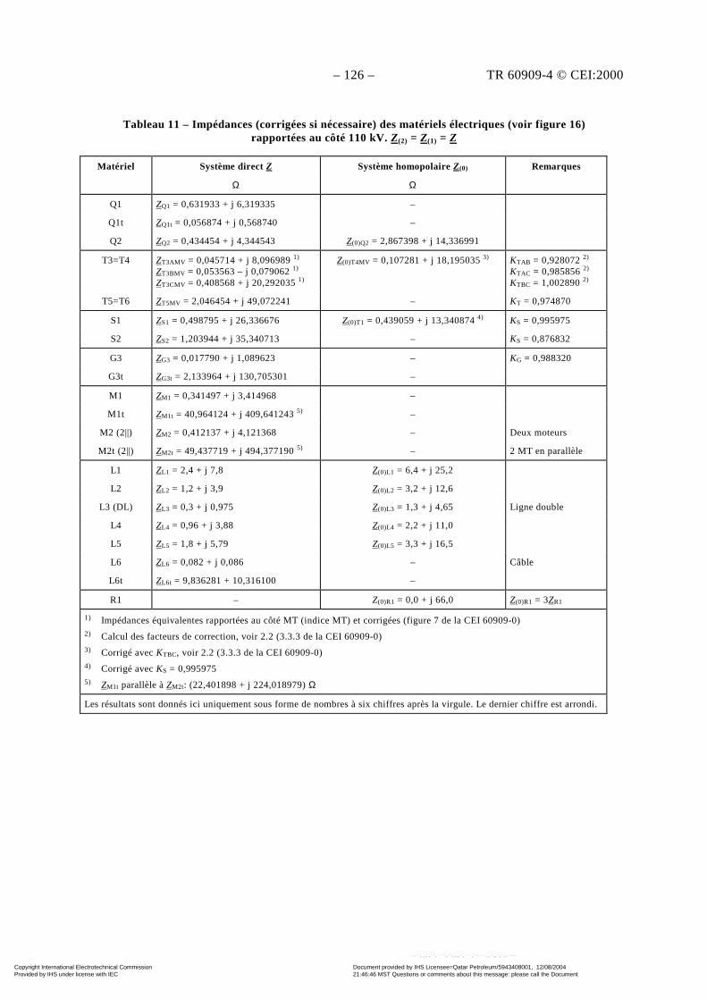
– 126 – TR 60909-4 © CEI:2000
Tableau 11 – Impédances (corrigées si nécessaire) des matériels électriques (voir figure 16)rapportées au côté 110 kV. Z(2) = Z(1) = Z
Matériel RemarquesSystème direct Z
Ω
Système homopolaire Z(0)
Ω
Q1 ZQ1 = 0,631933 + j 6,319335 –
Q1t ZQ1t = 0,056874 + j 0,568740 –
Q2 ZQ2 = 0,434454 + j 4,344543 Z(0)Q2 = 2,867398 + j 14,336991
T3=T4 ZT3AMV = 0,045714 + j 8,096989 1)
ZT3BMV = 0,053563 – j 0,079062 1)
ZT3CMV = 0,408568 + j 20,292035 1)
Z(0)T4MV = 0,107281 + j 18,195035 3) KTAB = 0,928072 2)
KTAC = 0,985856 2)
KTBC = 1,002890 2)
T5=T6 ZT5MV = 2,046454 + j 49,072241 – KT = 0,974870
S1 ZS1 = 0,498795 + j 26,336676 Z(0)T1 = 0,439059 + j 13,340874 4) KS = 0,995975
S2 ZS2 = 1,203944 + j 35,340713 – KS = 0,876832
G3 ZG3 = 0,017790 + j 1,089623 – KG = 0,988320
G3t ZG3t = 2,133964 + j 130,705301 –
M1 ZM1 = 0,341497 + j 3,414968 –
M1t ZM1t = 40,964124 + j 409,641243 5) –
M2 (2||) ZM2 = 0,412137 + j 4,121368 – Deux moteurs
M2t (2||) ZM2t = 49,437719 + j 494,377190 5) – 2 MT en parallèle
L1 ZL1 = 2,4 + j 7,8 Z(0)L1 = 6,4 + j 25,2
L2 ZL2 = 1,2 + j 3,9 Z(0)L2 = 3,2 + j 12,6
L3 (DL) ZL3 = 0,3 + j 0,975 Z(0)L3 = 1,3 + j 4,65 Ligne double
L4 ZL4 = 0,96 + j 3,88 Z(0)L4 = 2,2 + j 11,0
L5 ZL5 = 1,8 + j 5,79 Z(0)L5 = 3,3 + j 16,5
L6 ZL6 = 0,082 + j 0,086 – Câble
L6t ZL6t = 9,836281 + 10,316100 –
R1 – Z(0)R1 = 0,0 + j 66,0 Z(0)R1 = 3ZR1
1) Impédances équivalentes rapportées au côté MT (indice MT) et corrigées (figure 7 de la CEI 60909-0)2) Calcul des facteurs de correction, voir 2.2 (3.3.3 de la CEI 60909-0)3) Corrigé avec KTBC, voir 2.2 (3.3.3 de la CEI 60909-0)4) Corrigé avec KS = 0,9959755) ZM1t parallèle à ZM2t: (22,401898 + j 224,018979) Ω
Les résultats sont donnés ici uniquement sous forme de nombres à six chiffres après la virgule. Le dernier chiffre est arrondi.
Copyright International Electrotechnical Commission Provided by IHS under license with IEC
Document provided by IHS Licensee=Qatar Petroleum/5943408001, 12/08/200421:46:46 MST Questions or comments about this message: please call the DocumentPolicy Group at 303-397-2295.
--``,,,,,``,````,``,,,,`,```,``-`-`,,`,,`,`,,`---
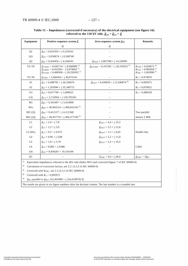
TR 60909-4 © IEC:2000 – 127 –
Table 11 – Impedances (corrected if necessary) of the electrical equipment (see figure 16)referred to the 110 kV side. Z(2) = Z(1) = Z
Equipment RemarksPositive-sequence system Z
Ω
Zero-sequence system Z(0)
Ω
Q1 ZQ1 = 0,631933 + j 6,319335 –
Q1t ZQ1t = 0,056874 + j 0,568740 –
Q2 ZQ2 = 0,434454 + j 4,344543 Z(0)Q2 = 2,867398 + j 14,336991
T3=T4 ZT3AMV = 0,045714 + j 8,096989 1)
ZT3BMV = 0,053563 – j 0,079062 1)
ZT3CMV = 0,408568 + j 20,292035 1)
Z(0)T4MV = 0,107281 + j 18,195035 3) KTAB = 0,928072 2)
KTAC = 0,985856 2)
KTBC = 1,002890 2)
T5=T6 ZT5MV = 2,046454 + j 49,072241 – KT = 0,974870
S1 ZS1 = 0,498795 + j 26,336676 Z(0)T1 = 0,439059 + j 13,340874 4) KS = 0,995975
S2 ZS2 = 1,203944 + j 35,340713 – KS = 0,876832
G3 ZG3 = 0,017790 + j 1,089623 – KG = 0,988320
G3t ZG3t = 2,133964 + j 130,705301 –
M1 ZM1 = 0,341497 + j 3,414968 –
M1t ZM1t = 40,964124 + j 409,641243 5) –
M2 (2||) ZM2 = 0,412137 + j 4,121368 – Two parallel
M2t (2||) ZM2t = 49,437719 + j 494,377190 5) – motors 2 MW
L1 ZL1 = 2,4 + j 7,8 Z(0)L1 = 6,4 + j 25,2
L2 ZL2 = 1,2 + j 3,9 Z(0)L2 = 3,2 + j 12,6
L3 (DL) ZL3 = 0,3 + j 0,975 Z(0)L3 = 1,3 + j 4,65 Double line
L4 ZL4 = 0,96 + j 3,88 Z(0)L4 = 2,2 + j 11,0
L5 ZL5 = 1,8 + j 5,79 Z(0)L5 = 3,3 + j 16,5
L6 ZL6 = 0,082 + j 0,086 – Cable
L6t ZL6t = 9,836281 + 10,316100 –
R1 – Z(0)R1 = 0,0 + j 66,0 Z(0)R1 = 3ZR1
1) Equivalent impedances referred to the MV-side (Index MV) and corrected (figure 7 of IEC 60909-0)2) Calculation of correction factors, see 2.2. (3.3.3 of IEC 60909-0)3) Corrected with KTBC, see 2.2 (3.3.3 of IEC 60909-0)4) Corrected with KS = 0,9959755) ZM1t parallel to ZM2t: (22,401898 + j 224,018979) Ω
The results are given in six-figure numbers after the decimal comma. The last number is a rounded one.
Copyright International Electrotechnical Commission Provided by IHS under license with IEC
Document provided by IHS Licensee=Qatar Petroleum/5943408001, 12/08/200421:46:46 MST Questions or comments about this message: please call the DocumentPolicy Group at 303-397-2295.
--``,,,,,``,````,``,,,,`,```,``-`-`,,`,,`,`,,`---
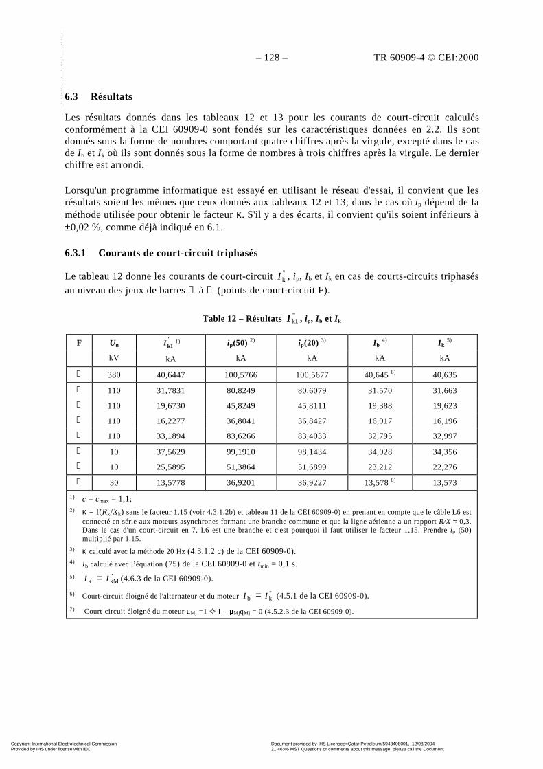
– 128 – TR 60909-4 © CEI:2000
6.3 Résultats
Les résultats donnés dans les tableaux 12 et 13 pour les courants de court-circuit calculésconformément à la CEI 60909-0 sont fondés sur les caractéristiques données en 2.2. Ils sontdonnés sous la forme de nombres comportant quatre chiffres après la virgule, excepté dans le casde Ib et Ik où ils sont donnés sous la forme de nombres à trois chiffres après la virgule. Le dernierchiffre est arrondi.
Lorsqu'un programme informatique est essayé en utilisant le réseau d'essai, il convient que lesrésultats soient les mêmes que ceux donnés aux tableaux 12 et 13; dans le cas où ip dépend de laméthode utilisée pour obtenir le facteur κ. S'il y a des écarts, il convient qu'ils soient inférieurs à±0,02 %, comme déjà indiqué en 6.1.
6.3.1 Courants de court-circuit triphasés
Le tableau 12 donne les courants de court-circuit "kI , ip, Ib et Ik en cas de courts-circuits triphasés
au niveau des jeux de barres ➀ à ➇ (points de court-circuit F).
Table 12 – Résultats "k1I , ip, I b et I k
F Un
kV
"k1I 1)
kA
ip(50) 2)
kA
ip(20) 3)
kA
I b 4)
kA
I k 5)
kA
➀ 380 40,6447 100,5766 100,5677 40,645 6) 40,635
➁ 110 31,7831 80,8249 80,6079 31,570 31,663
➂ 110 19,6730 45,8249 45,8111 19,388 19,623
➃ 110 16,2277 36,8041 36,8427 16,017 16,196
➄ 110 33,1894 83,6266 83,4033 32,795 32,997
➅ 10 37,5629 99,1910 98,1434 34,028 34,356
➆ 10 25,5895 51,3864 51,6899 23,212 22,276
➇ 30 13,5778 36,9201 36,9227 13,578 6) 13,573
1) c = cmax = 1,1;2) κ = f(Rk/Xk) sans le facteur 1,15 (voir 4.3.1.2b) et tableau 11 de la CEI 60909-0) en prenant en compte que le câble L6 est
connecté en série aux moteurs asynchrones formant une branche commune et que la ligne aérienne a un rapport R/X ≈ 0,3.Dans le cas d'un court-circuit en 7, L6 est une branche et c'est pourquoi il faut utiliser le facteur 1,15. Prendre ip (50)multiplié par 1,15.
3) κ calculé avec la méthode 20 Hz (4.3.1.2 c) de la CEI 60909-0).4) Ib calculé avec l’équation (75) de la CEI 60909-0 et tmin = 0,1 s.
5) "Mkk II = (4.6.3 de la CEI 60909-0).
6) Court-circuit éloigné de l'alternateur et du moteur "kb II = (4.5.1 de la CEI 60909-0).
7) Court-circuit éloigné du moteur Mj =1 ± MjqMj = 0 (4.5.2.3 de la CEI 60909-0).
Copyright International Electrotechnical Commission Provided by IHS under license with IEC
Document provided by IHS Licensee=Qatar Petroleum/5943408001, 12/08/200421:46:46 MST Questions or comments about this message: please call the DocumentPolicy Group at 303-397-2295.
--``,,,,,``,````,``,,,,`,```,``-`-`,,`,,`,`,,`---
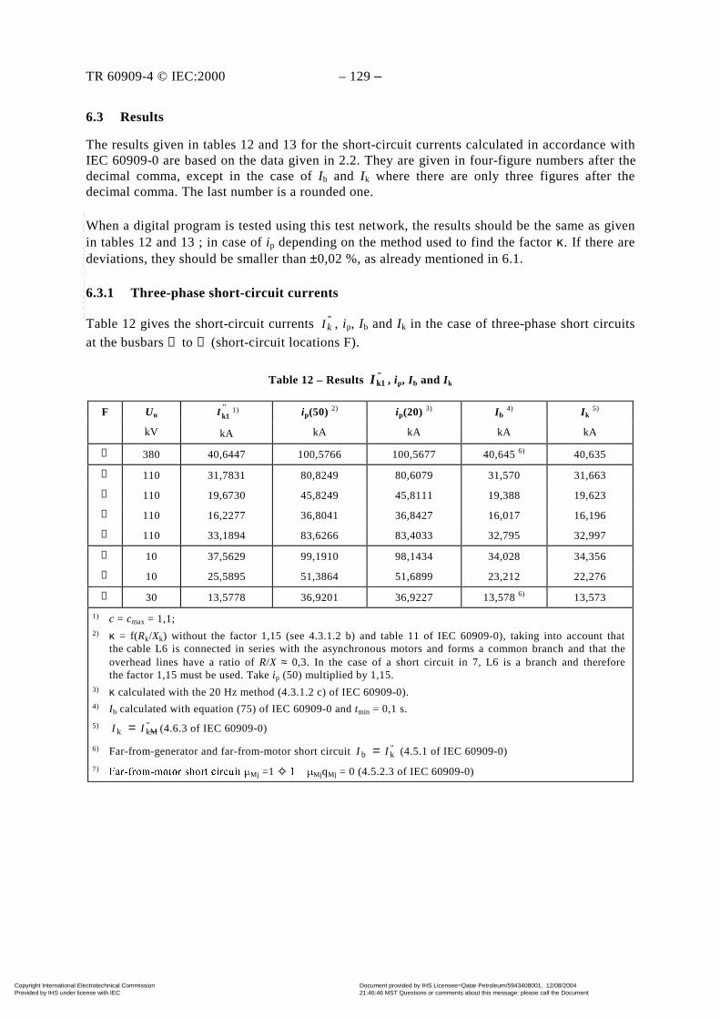
TR 60909-4 © IEC:2000 – 129 –
6.3 Results
The results given in tables 12 and 13 for the short-circuit currents calculated in accordance withIEC 60909-0 are based on the data given in 2.2. They are given in four-figure numbers after thedecimal comma, except in the case of Ib and Ik where there are only three figures after thedecimal comma. The last number is a rounded one.
When a digital program is tested using this test network, the results should be the same as givenin tables 12 and 13 ; in case of ip depending on the method used to find the factor κ. If there aredeviations, they should be smaller than ±0,02 %, as already mentioned in 6.1.
6.3.1 Three-phase short-circuit currents
Table 12 gives the short-circuit currents "kI , ip, Ib and Ik in the case of three-phase short circuits
at the busbars ➀ to ➇ (short-circuit locations F).
Table 12 – Results "k1I , ip, I b and I k
F Un
kV
"k1I 1)
kA
ip(50) 2)
kA
ip(20) 3)
kA
I b 4)
kA
I k 5)
kA
➀ 380 40,6447 100,5766 100,5677 40,645 6) 40,635
➁ 110 31,7831 80,8249 80,6079 31,570 31,663
➂ 110 19,6730 45,8249 45,8111 19,388 19,623
➃ 110 16,2277 36,8041 36,8427 16,017 16,196
➄ 110 33,1894 83,6266 83,4033 32,795 32,997
➅ 10 37,5629 99,1910 98,1434 34,028 34,356
➆ 10 25,5895 51,3864 51,6899 23,212 22,276
➇ 30 13,5778 36,9201 36,9227 13,578 6) 13,573
1) c = cmax = 1,1;2) κ = f(Rk/Xk) without the factor 1,15 (see 4.3.1.2 b) and table 11 of IEC 60909-0), taking into account that
the cable L6 is connected in series with the asynchronous motors and forms a common branch and that theoverhead lines have a ratio of R/X ≈ 0,3. In the case of a short circuit in 7, L6 is a branch and thereforethe factor 1,15 must be used. Take ip (50) multiplied by 1,15.
3) κ calculated with the 20 Hz method (4.3.1.2 c) of IEC 60909-0).4) Ib calculated with equation (75) of IEC 60909-0 and tmin = 0,1 s.
5) "Mkk II = (4.6.3 of IEC 60909-0)
6) Far-from-generator and far-from-motor short circuit "kb II = (4.5.1 of IEC 60909-0)
7) )DUIURPPRWRU VKRUW FLUFXLW Mj =1 ± MjqMj = 0 (4.5.2.3 of IEC 60909-0)
Copyright International Electrotechnical Commission Provided by IHS under license with IEC
Document provided by IHS Licensee=Qatar Petroleum/5943408001, 12/08/200421:46:46 MST Questions or comments about this message: please call the DocumentPolicy Group at 303-397-2295.
--``,,,,,``,````,``,,,,`,```,``-`-`,,`,,`,`,,`---
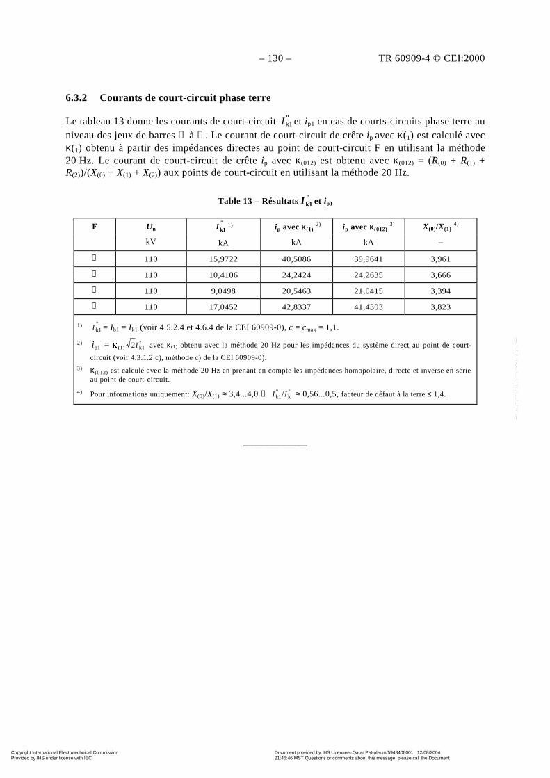
– 130 – TR 60909-4 © CEI:2000
6.3.2 Courants de court-circuit phase terre
Le tableau 13 donne les courants de court-circuit "k1I et ip1 en cas de courts-circuits phase terre au
niveau des jeux de barres ➁ à ➄. Le courant de court-circuit de crête ip avec κ(1) est calculé avecκ(1) obtenu à partir des impédances directes au point de court-circuit F en utilisant la méthode20 Hz. Le courant de court-circuit de crête ip avec κ(012) est obtenu avec κ(012) = (R(0) + R(1) +R(2))/(X(0) + X(1) + X(2)) aux points de court-circuit en utilisant la méthode 20 Hz.
Table 13 – Résultats "k1I et ip1
F Un
kV
"k1I 1)
kA
ip avec κ(1) 2)
kA
ip avec κ(012) 3)
kA
X(0)/X(1) 4)
–
➁ 110 15,9722 40,5086 39,9641 3,961
➂ 110 10,4106 24,2424 24,2635 3,666
➃ 110 9,0498 20,5463 21,0415 3,394
➄ 110 17,0452 42,8337 41,4303 3,823
1) "k1I = Ib1 = Ik1 (voir 4.5.2.4 et 4.6.4 de la CEI 60909-0), c = cmax = 1,1.
2) "k1(1)p1 2 Ii = avec κ(1) obtenu avec la méthode 20 Hz pour les impédances du système direct au point de court-
circuit (voir 4.3.1.2 c), méthode c) de la CEI 60909-0).3) κ(012) est calculé avec la méthode 20 Hz en prenant en compte les impédances homopolaire, directe et inverse en série
au point de court-circuit.
4) Pour informations uniquement: X(0)/X(1) ≈ 3,4...4,0 → "k
"k1/ II ≈ 0,56...0,5, facteur de défaut à la terre ≤ 1,4.
____________
Copyright International Electrotechnical Commission Provided by IHS under license with IEC
Document provided by IHS Licensee=Qatar Petroleum/5943408001, 12/08/200421:46:46 MST Questions or comments about this message: please call the DocumentPolicy Group at 303-397-2295.
--``,,,,,``,````,``,,,,`,```,``-`-`,,`,,`,`,,`---
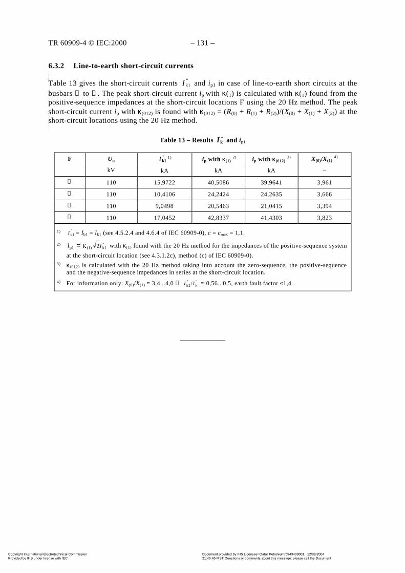
TR 60909-4 © IEC:2000 – 131 –
6.3.2 Line-to-earth short-circuit currents
Table 13 gives the short-circuit currents "k1I and ip1 in case of line-to-earth short circuits at the
busbars ➁ to ➄. The peak short-circuit current ip with κ(1) is calculated with κ(1) found from thepositive-sequence impedances at the short-circuit locations F using the 20 Hz method. The peakshort-circuit current ip with κ(012) is found with κ(012) = (R(0) + R(1) + R(2))/(X(0) + X(1) + X(2)) at theshort-circuit locations using the 20 Hz method.
Table 13 – Results "kI and ip1
F Un
kV
"k1I 1)
kA
ip with κ(1) 2)
kA
ip with κ(012) 3)
kA
X(0)/X(1) 4)
–
➁ 110 15,9722 40,5086 39,9641 3,961
➂ 110 10,4106 24,2424 24,2635 3,666
➃ 110 9,0498 20,5463 21,0415 3,394
➄ 110 17,0452 42,8337 41,4303 3,823
1) "k1I = Ib1 = Ik1 (see 4.5.2.4 and 4.6.4 of IEC 60909-0), c = cmax = 1,1.
2) "k1(1)p1 2 Ii = with κ(1) found with the 20 Hz method for the impedances of the positive-sequence system
at the short-circuit location (see 4.3.1.2c), method (c) of IEC 60909-0).3) κ(012) is calculated with the 20 Hz method taking into account the zero-sequence, the positive-sequence
and the negative-sequence impedances in series at the short-circuit location.
4) For information only: X(0)/X(1) ≈ 3,4...4,0 → "k
"k1/ II ≈ 0,56...0,5, earth fault factor ≤1,4.
____________
Copyright International Electrotechnical Commission Provided by IHS under license with IEC
Document provided by IHS Licensee=Qatar Petroleum/5943408001, 12/08/200421:46:46 MST Questions or comments about this message: please call the DocumentPolicy Group at 303-397-2295.
--``,,,,,``,````,``,,,,`,```,``-`-`,,`,,`,`,,`---
Standards Survey
The IEC would like to offer you the best quality standards possible. To make sure that wecontinue to meet your needs, your feedback is essential. Would you please take a minuteto answer the questions overleaf and fax them to us at +41 22 919 03 00 or mail them tothe address below. Thank you!
Customer Service Centre (CSC)
International Electrotechnical Commission3, rue de Varembé1211 Genève 20Switzerland
or
Fax to: IEC/CSC at +41 22 919 03 00
Thank you for your contribution to the standards-making process.
Non affrancareNo stamp required
Nicht frankierenNe pas affranchir
A Prioritaire
RÉPONSE PAYÉE
SUISSE
Customer Service Centre (CSC)International Electrotechnical Commission3, rue de Varembé1211 GENEVA 20Switzerland
Copyright International Electrotechnical Commission Provided by IHS under license with IEC
Document provided by IHS Licensee=Qatar Petroleum/5943408001, 12/08/200421:46:46 MST Questions or comments about this message: please call the DocumentPolicy Group at 303-397-2295.
--``,,,,,``,````,``,,,,`,```,``-`-`,,`,,`,`,,`---

Q1 Please report on ONE STANDARD andONE STANDARD ONLY . Enter the exactnumber of the standard: (e.g. 60601-1-1)
.............................................................
Q2 Please tell us in what capacity(ies) youbought the standard (tick all that apply).I am the/a:
purchasing agent R
librarian R
researcher R
design engineer R
safety engineer R
testing engineer R
marketing specialist R
other.....................................................
Q3 I work for/in/as a:(tick all that apply)
manufacturing R
consultant R
government R
test/certification facility R
public utility R
education R
military R
other.....................................................
Q4 This standard will be used for:(tick all that apply)
general reference R
product research R
product design/development R
specifications R
tenders R
quality assessment R
certification R
technical documentation R
thesis R
manufacturing R
other.....................................................
Q5 This standard meets my needs:(tick one)
not at all R
nearly R
fairly well R
exactly R
Q6 If you ticked NOT AT ALL in Question 5the reason is: (tick all that apply)
standard is out of date R
standard is incomplete R
standard is too academic R
standard is too superficial R
title is misleading R
I made the wrong choice R
other ....................................................
Q7 Please assess the standard in thefollowing categories, usingthe numbers:(1) unacceptable,(2) below average,(3) average,(4) above average,(5) exceptional,(6) not applicable
timeliness .............................................quality of writing....................................technical contents.................................logic of arrangement of contents ..........tables, charts, graphs, figures ...............other ....................................................
Q8 I read/use the: (tick one)
French text only R
English text only R
both English and French texts R
Q9 Please share any comment on anyaspect of the IEC that you would likeus to know:
............................................................
............................................................
............................................................
............................................................
............................................................
............................................................
............................................................
............................................................
............................................................
............................................................
............................................................
............................................................
Copyright International Electrotechnical Commission Provided by IHS under license with IEC
Document provided by IHS Licensee=Qatar Petroleum/5943408001, 12/08/200421:46:46 MST Questions or comments about this message: please call the DocumentPolicy Group at 303-397-2295.
--``,,,,,``,````,``,,,,`,```,``-`-`,,`,,`,`,,`---
Enquête sur les normes
La CEI ambitionne de vous offrir les meilleures normes possibles. Pour nous assurerque nous continuons à répondre à votre attente, nous avons besoin de quelquesrenseignements de votre part. Nous vous demandons simplement de consacrer un instantpour répondre au questionnaire ci-après et de nous le retourner par fax au+41 22 919 03 00 ou par courrier à l’adresse ci-dessous. Merci !
Centre du Service Clientèle (CSC)
Commission Electrotechnique Internationale3, rue de Varembé1211 Genève 20Suisse
ou
Télécopie: CEI/CSC +41 22 919 03 00
Nous vous remercions de la contribution que vous voudrez bien apporter ainsià la Normalisation Internationale.
Non affrancareNo stamp required
Nicht frankierenNe pas affranchir
A Prioritaire
RÉPONSE PAYÉE
SUISSE
Centre du Service Clientèle (CSC)Commission Electrotechnique Internationale3, rue de Varembé1211 GENÈVE 20Suisse
Copyright International Electrotechnical Commission Provided by IHS under license with IEC
Document provided by IHS Licensee=Qatar Petroleum/5943408001, 12/08/200421:46:46 MST Questions or comments about this message: please call the DocumentPolicy Group at 303-397-2295.
--``,,,,,``,````,``,,,,`,```,``-`-`,,`,,`,`,,`---
Q1 Veuillez ne mentionner qu’UNE SEULENORME et indiquer son numéro exact:(ex. 60601-1-1)
.............................................................
Q2 En tant qu’acheteur de cette norme,quelle est votre fonction?(cochez tout ce qui convient)Je suis le/un:
agent d’un service d’achat R
bibliothécaire R
chercheur R
ingénieur concepteur R
ingénieur sécurité R
ingénieur d’essais R
spécialiste en marketing R
autre(s).................................................
Q3 Je travaille:(cochez tout ce qui convient)
dans l’industrie R
comme consultant R
pour un gouvernement R
pour un organisme d’essais/ certification R
dans un service public R
dans l’enseignement R
comme militaire R
autre(s).................................................
Q4 Cette norme sera utilisée pour/comme(cochez tout ce qui convient)
ouvrage de référence R
une recherche de produit R
une étude/développement de produit R
des spécifications R
des soumissions R
une évaluation de la qualité R
une certification R
une documentation technique R
une thèse R
la fabrication R
autre(s).................................................
Q5 Cette norme répond-elle à vos besoins:(une seule réponse)
pas du tout R
à peu près R
assez bien R
parfaitement R
Q6 Si vous avez répondu PAS DU TOUT àQ5, c’est pour la/les raison(s) suivantes:(cochez tout ce qui convient)
la norme a besoin d’être révisée R
la norme est incomplète R
la norme est trop théorique R
la norme est trop superficielle R
le titre est équivoque R
je n’ai pas fait le bon choix R
autre(s) ................................................
Q7 Veuillez évaluer chacun des critères ci-dessous en utilisant les chiffres(1) inacceptable,(2) au-dessous de la moyenne,(3) moyen,(4) au-dessus de la moyenne,(5) exceptionnel,(6) sans objet
publication en temps opportun ..............qualité de la rédaction...........................contenu technique ................................disposition logique du contenu ..............tableaux, diagrammes, graphiques, figures ................................................autre(s) ................................................
Q8 Je lis/utilise: (une seule réponse)
uniquement le texte français R
uniquement le texte anglais R
les textes anglais et français R
Q9 Veuillez nous faire part de vosobservations éventuelles sur la CEI:
............................................................
............................................................
............................................................
............................................................
............................................................
............................................................
Copyright International Electrotechnical Commission Provided by IHS under license with IEC
Document provided by IHS Licensee=Qatar Petroleum/5943408001, 12/08/200421:46:46 MST Questions or comments about this message: please call the DocumentPolicy Group at 303-397-2295.
--``,,,,,``,````,``,,,,`,```,``-`-`,,`,,`,`,,`---

ISBN 2-8318-5314-1
&1+', ;8647:ICS 17.220.01; 29.240.20
Typeset and printed by the IEC Central OfficeGENEVA, SWITZERLAND
Copyright International Electrotechnical Commission Provided by IHS under license with IEC
Document provided by IHS Licensee=Qatar Petroleum/5943408001, 12/08/200421:46:46 MST Questions or comments about this message: please call the DocumentPolicy Group at 303-397-2295.
--``,,,,,``,````,``,,,,`,```,``-`-`,,`,,`,`,,`---