
Protocol Gateway IEC60870-5-103 Master/Slave€¦ · Protocol Gateway IEC60870-5-103 Master/Slave...
38
Protocol Gateway IEC60870-5-103 Master/Slave Protocol and eNode Designer configuration eNode Configuration Manual V1.3 September 29 th , 2017 Atop Technologies, Inc.
Transcript of Protocol Gateway IEC60870-5-103 Master/Slave€¦ · Protocol Gateway IEC60870-5-103 Master/Slave...

Protocol Gateway
IEC60870-5-103 Master/Slave
Protocol and eNode Designer configuration
eNode Configuration Manual V1.3
September 29th, 2017
Atop Technologies, Inc.

IEC 60870-5-103 User Manual Introduction
Page 2 of 38
This PDF Document contains internal hyperlinks for ease of navigation. For example, click on any item listed in the Table of Contents to go to that page.
Configuration Guide Interoperability
Published by:
Atop Technologies, Inc. 2F, No. 146, Sec. 1, Tung-Hsing Rd, 30261 Chupei City, Hsinchu County Taiwan, R.O.C. Tel: +886-3-550-8137 Fax: +886-3-550-8131 www.atoponline.com www.atop.com.tw

IEC 60870-5-103 User Manual Introduction
Page 3 of 38
Important Announcement The information contained in this document is the property of Atop technologies, Inc., and is supplied for the sole purpose of operation and maintenance of Atop Technologies, Inc., products. No part of this publication is to be used for any other purposes, and it is not to be reproduced, copied, disclosed, transmitted, stored in a retrieval system, or translated into any human or computer language, in any form, by any means, in whole or in part, without the prior explicit written consent of Atop Technologies, Inc., Offenders will be held liable for damages and prosecution. All rights, including rights created by patent grant or registration of a utility model or design, are reserved.
Disclaimer We have checked the contents of this manual for agreement with the hardware and the software described. Since deviations cannot be precluded entirely, we cannot guarantee full agreement. However, the data in this manual is reviewed regularly and any necessary corrections will be included in subsequent editions. Suggestions for improvement are welcome. All other product’s names referenced herein are registered trademarks of their respective companies.
Documentation Control
Author: Matteo Tabarelli
Revision: 1.3 Enhancement
Revision History: Modify because of software enhancements
Creation Date: 14 December 2015
Last Revision Date: 29 September 2017
Product Reference: PG59XX Protocol Gateway
Document Status: Released
IEC 60870-5-103 User Manual Introduction
Page 4 of 38
Table of Contents
1 Introduction .............................................................................................................................. 7
1.1 Scope ............................................................................................................................................................7 1.2 Document Reference ...................................................................................................................................7 1.3 List of Abbreviations ....................................................................................................................................7
2 General Description .................................................................................................................. 8
2.1 IEC 60870-5-103 Standard ..........................................................................................................................8 2.2 ISO/OSI of IEC 60870-5-103 ........................................................................................................................8 2.3 Configuration Theory ...................................................................................................................................9 2.4 General Screen Description ...................................................................................................................... 10
3 IEC60870-5-103 Configuration Guide .................................................................................. 11
3.1 Adding the Module in eNode Designer .................................................................................................... 11 3.2 Server IED Properties ................................................................................................................................ 11
3.2.1.1 Common Address ............................................................................................................... 12 3.3 Client Configuration .................................................................................................................................. 13
3.3.1 Client Settings......................................................................................................................... 14 3.3.1.1 Link Address........................................................................................................................ 14 3.3.1.2 Link Layer Timeout (ms) ..................................................................................................... 14 3.3.1.3 Station Initialisation ............................................................................................................ 14 3.3.1.4 Time Sync Interval (s) ......................................................................................................... 14 3.3.1.5 General Interrogation Interval (s) ....................................................................................... 14 3.3.1.6 Poll Class Interval (ms) ...................................................................................................... 14 3.3.1.7 Command Timeout (ms) .................................................................................................... 15 3.3.2 Adding Data Points ................................................................................................................. 16 3.3.2.1 Add a Single Data Point ...................................................................................................... 17 3.3.3 Connected Servers (Remote IEDs) ........................................................................................ 18
3.4 Server Configuration ................................................................................................................................. 19 3.4.1 Server Settings........................................................................................................................ 20 3.4.1.1 Link Address........................................................................................................................ 20 3.4.1.2 Common Address ............................................................................................................... 20 3.4.1.3 Link Layer Timeout (ms) ..................................................................................................... 20 3.4.1.4 Command Timeout (ms) ................................................................................................... 20 3.4.1.5 Class {X} Event Buffer Size ................................................................................................. 20 3.4.1.6 Class {X} Event Buffer Overflow Percentage ..................................................................... 20 3.4.2 Adding Data Point References ............................................................................................... 21
3.5 Miscellaneous Common........................................................................................................................... 23 3.5.1 Incomplete, Conflicting and not needed Information ........................................................... 23 3.5.2 Modify Selected Points Window ............................................................................................ 24
4 Communication Port Properties .......................................................................................... 25
5 Using Counters ...................................................................................................................... 26
6 Interoperability....................................................................................................................... 27
6.1 Physical layer ............................................................................................................................................ 27 6.1.1 Electrical Interface.................................................................................................................. 27 6.1.2 Optical Interface ..................................................................................................................... 27 6.1.3 Transmission speed ............................................................................................................... 27
6.2 Link Layer .................................................................................................................................................. 28 6.3 Application Layer ...................................................................................................................................... 28
6.3.1 Transmission mode for application data .............................................................................. 28
IEC 60870-5-103 User Manual Introduction
Page 5 of 38
6.3.2 Common address of ASDU .................................................................................................... 28 6.3.3 Selection of standard information numbers in monitor direction ....................................... 28 6.3.3.1 System functions in monitor direction .............................................................................. 28 6.3.3.2 Status indications in monitor direction ............................................................................. 28 6.3.3.3 Supervision indications in monitor direction ..................................................................... 29 6.3.3.4 Earth fault indications in monitor direction ....................................................................... 29 6.3.3.5 Fault indications in monitor direction ................................................................................ 29 6.3.3.6 Auto-reclosure indications in monitor direction ................................................................ 30 6.3.3.7 Measurands in monitor direction ....................................................................................... 30 6.3.3.8 Generic functions in monitor direction .............................................................................. 30 6.3.4 Selection of standard information numbers in control direction ........................................ 30 6.3.4.1 System functions in control direction ................................................................................ 30 6.3.4.2 General commands in control direction ........................................................................... 30 6.3.4.3 General functions in control direction .............................................................................. 31 6.3.5 Basic application functions ................................................................................................... 31 6.3.6 Miscellaneous ......................................................................................................................... 31
7 Reference Guide .................................................................................................................... 32
7.1 Table Buttons ............................................................................................................................................ 32 7.2 Table Columns .......................................................................................................................................... 32
7.2.1.1 Tag ....................................................................................................................................... 32 7.2.1.2 Description .......................................................................................................................... 32 7.2.1.3 Function Type ...................................................................................................................... 32 7.2.1.4 Type ID ................................................................................................................................. 33 7.2.1.5 Information Number ........................................................................................................... 33 7.2.1.6 Data Object .......................................................................................................................... 36 7.2.1.7 Class .................................................................................................................................... 36 7.2.1.8 Cyclic Transmission Time (s) ............................................................................................ 36
7.3 IEC 60870-5-103’s Related ADH Types.................................................................................................... 37
Table of Figures Figure 2-1 - Example screen. ......................................................................................................................................... 10 Figure 3-1 - Adding the module in eNode Designer. ..................................................................................................... 11 Figure 3-2 - Client settings panel. .................................................................................................................................. 13 Figure 3-3 - Client IED panel. .......................................................................................................................................... 13 Figure 3-4 - Add data points window............................................................................................................................. 16 Figure 3-5 - Adding a single data point with +1 button. ............................................................................................... 17 Figure 3-6 - Multiple connected servers example. ....................................................................................................... 18 Figure 3-7 - Add a connected server. ............................................................................................................................ 18 Figure 3-8 - Remove a connected server. ..................................................................................................................... 18 Figure 3-9 - Server settings panel. ................................................................................................................................. 19 Figure 3-10 – Server IED panel. ..................................................................................................................................... 19 Figure 3-11 - Add new references window.................................................................................................................... 21 Figure 3-12 - Data point references added. .................................................................................................................. 22 Figure 3-13 - Data type restricted drop down menu example...................................................................................... 22 Figure 3-14 - Server data point configuration example. ............................................................................................... 22 Figure 3-15 – Incomplete and missing information example. .................................................................................... 23 Figure 3-16 - Modify data points window example. ..................................................................................................... 24 Figure 4-1 - Serial port properties. ................................................................................................................................. 25 Figure 5-1 – Using Auto Increment when adding Data Points or Commands. ........................................................... 26

IEC 60870-5-103 User Manual Introduction
Page 6 of 38

IEC 60870-5-103 User Manual Introduction
Page 7 of 38
1 Introduction
Thank you for Buying Atop’s Protocol Gateway. The product is bundled with the following three user manuals:
1) Hardware specific installation user manual, not covered in this document. It covers Atop’s hardware installation procedure, wiring, power connection etc.
2) Getting started with Atop’s Protocol Gateway user manual – configuration tool introduction, web
configuration, software architecture introduction– not covered in this document. This manual covers the introduction, installation, network set-up maintenance and using of the configuration tool software, including the procedure to be followed for uploading new configurations to Atop’s device.
3) Protocol specific user manual (This Manual). One protocol-specific manual will be provided for each protocol installed on the device. This manual covers:
a. Basic device network configuration b. Step-by-step protocol set-up for in eNode designer c. Description of the protocol-specific software features, the device profile and the implementation
table of supported functionalities.
This manual is for IEC-60870-5-103 master/slave and describes how to use the IEC-60870-5-103 eNode Designer Module to configure Atop’s IEC 60870-5-101/103 ADH Application within the eNode Designer configuration tool.
1.1 Scope
This document is divided into 3 major sections:
General Description;
Configuration Guide; and
Interoperability
1.2 Document Reference
[1] Document Title: eNode Designer User Manual Revision: Version 1.00 [2] Document Title: IEC 60870-5-103 International Standard Revision: First Edition, December 1997
1.3 List of Abbreviations
ADH = Application Data Hub IEC = International Electrotechnical Commission IED = Intelligent Electronic Device
IEC 60870-5-103 User Manual General Description
Page 8 of 38
2 General Description
The IEC 60870-5-103 eNode Module can be used to configure the IEC 60870-5-103 ADH Application as a master or slave. For naming consistency across eNode Designer, the master is called a client, and the slave is called a server. The client can communicate with many servers, whose data point details can be configured using this module. Atop’s Protocol Gateway supports one server/slave per protocol per device.
2.1 IEC 60870-5-103 Standard
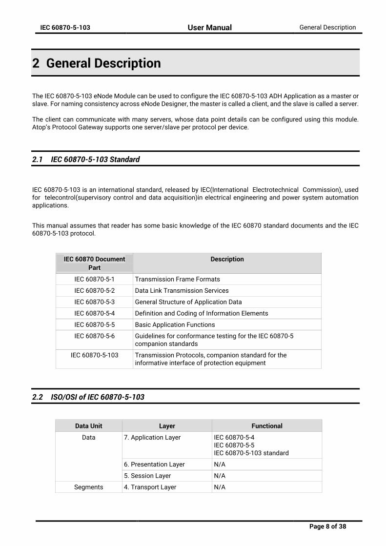
IEC 60870-5-103 is an international standard, released by IEC(International Electrotechnical Commission), used for telecontrol(supervisory control and data acquisition)in electrical engineering and power system automation applications.
This manual assumes that reader has some basic knowledge of the IEC 60870 standard documents and the IEC 60870-5-103 protocol.
IEC 60870 Document Part
Description
IEC 60870-5-1 Transmission Frame Formats
IEC 60870-5-2 Data Link Transmission Services
IEC 60870-5-3 General Structure of Application Data
IEC 60870-5-4 Definition and Coding of Information Elements
IEC 60870-5-5 Basic Application Functions
IEC 60870-5-6 Guidelines for conformance testing for the IEC 60870-5 companion standards
IEC 60870-5-103 Transmission Protocols, companion standard for the informative interface of protection equipment
2.2 ISO/OSI of IEC 60870-5-103
Data Unit Layer Functional
Data 7. Application Layer IEC 60870-5-4 IEC 60870-5-5 IEC 60870-5-103 standard
6. Presentation Layer N/A
5. Session Layer N/A
Segments 4. Transport Layer N/A
IEC 60870-5-103 User Manual General Description
Page 9 of 38
Packet/Datagram 3. Network Layer N/A
Bit/Frame 2. Data Link Layer Unbalanced IEC 60870-5-2 IEC 60870-5-1(FT 1.2)
1. Physical Layer RS232, RS422, RS485
2.3 Configuration Theory
Most configuration properties describe a server. When configuring the ADH application server, you are configuring the properties of the server itself. When configuring the ADH application client, you are describing the properties of all the remote servers with which the client is communicating. Configuring the protocol specific information (such as object addressing) is handled in the module. This is explained in this document. Communication port properties (such as Baud Rate) are configured on the communication port itself. The Device module handles the communication port properties, so heavy details are outside the scope of this document. Port configuration instructions are provide in the eNode Designer general user manual. However, screenshots of the typical configuration method are shown in section 4.
IEC 60870-5-103 User Manual General Description
Page 10 of 38
2.4 General Screen Description
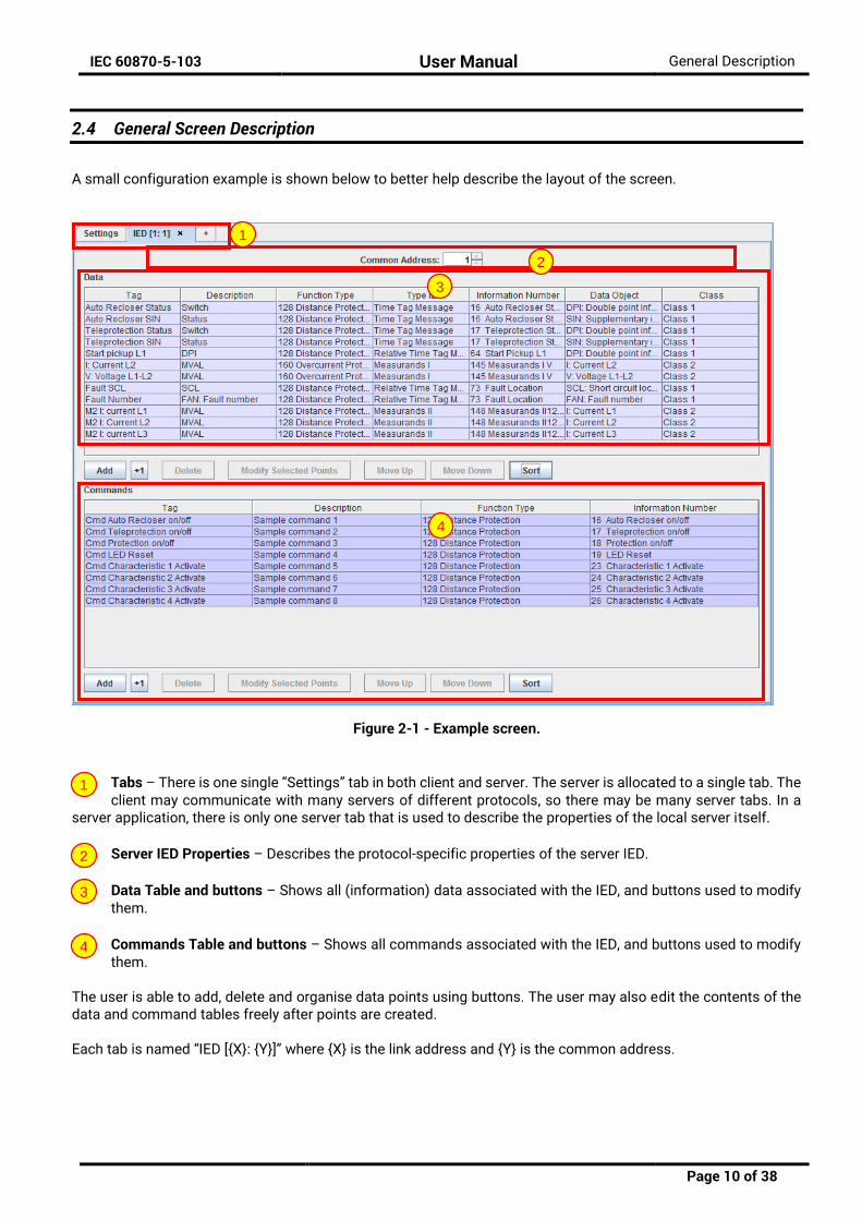
A small configuration example is shown below to better help describe the layout of the screen.
Figure 2-1 - Example screen.
Tabs – There is one single “Settings” tab in both client and server. The server is allocated to a single tab. The client may communicate with many servers of different protocols, so there may be many server tabs. In a
server application, there is only one server tab that is used to describe the properties of the local server itself.
Server IED Properties – Describes the protocol-specific properties of the server IED.
Data Table and buttons – Shows all (information) data associated with the IED, and buttons used to modify them.
Commands Table and buttons – Shows all commands associated with the IED, and buttons used to modify them.
The user is able to add, delete and organise data points using buttons. The user may also edit the contents of the data and command tables freely after points are created. Each tab is named “IED [{X}: {Y}]” where {X} is the link address and {Y} is the common address.
1
2
3
4
1
2
3
4
IEC 60870-5-103 User Manual IEC60870-5-103 Configuration Guide
Page 11 of 38
3 IEC60870-5-103 Configuration Guide
3.1 Adding the Module in eNode Designer
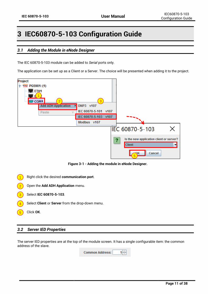
The IEC 60870-5-103 module can be added to Serial ports only. The application can be set up as a Client or a Server. The choice will be presented when adding it to the project.
Figure 3-1 - Adding the module in eNode Designer.
Right click the desired communication port.
Open the Add ADH Application menu.
Select IEC 60870-5-103.
Select Client or Server from the drop-down menu.
Click OK.
3.2 Server IED Properties
The server IED properties are at the top of the module screen. It has a single configurable item: the common address of the slave.
5
1
2 3
1
2
3
4
5

IEC 60870-5-103 User Manual IEC60870-5-103 Configuration Guide
Page 12 of 38
3.2.1.1 Common Address
Description The common address of the server (slave) IED. For server application it describes its own common address. For clients, it describes the common address of the remote server.
Data Entry Integer
Range 0 to 255
Input Option Mandatory
IEC 60870-5-103 User Manual IEC60870-5-103 Configuration Guide
Page 13 of 38
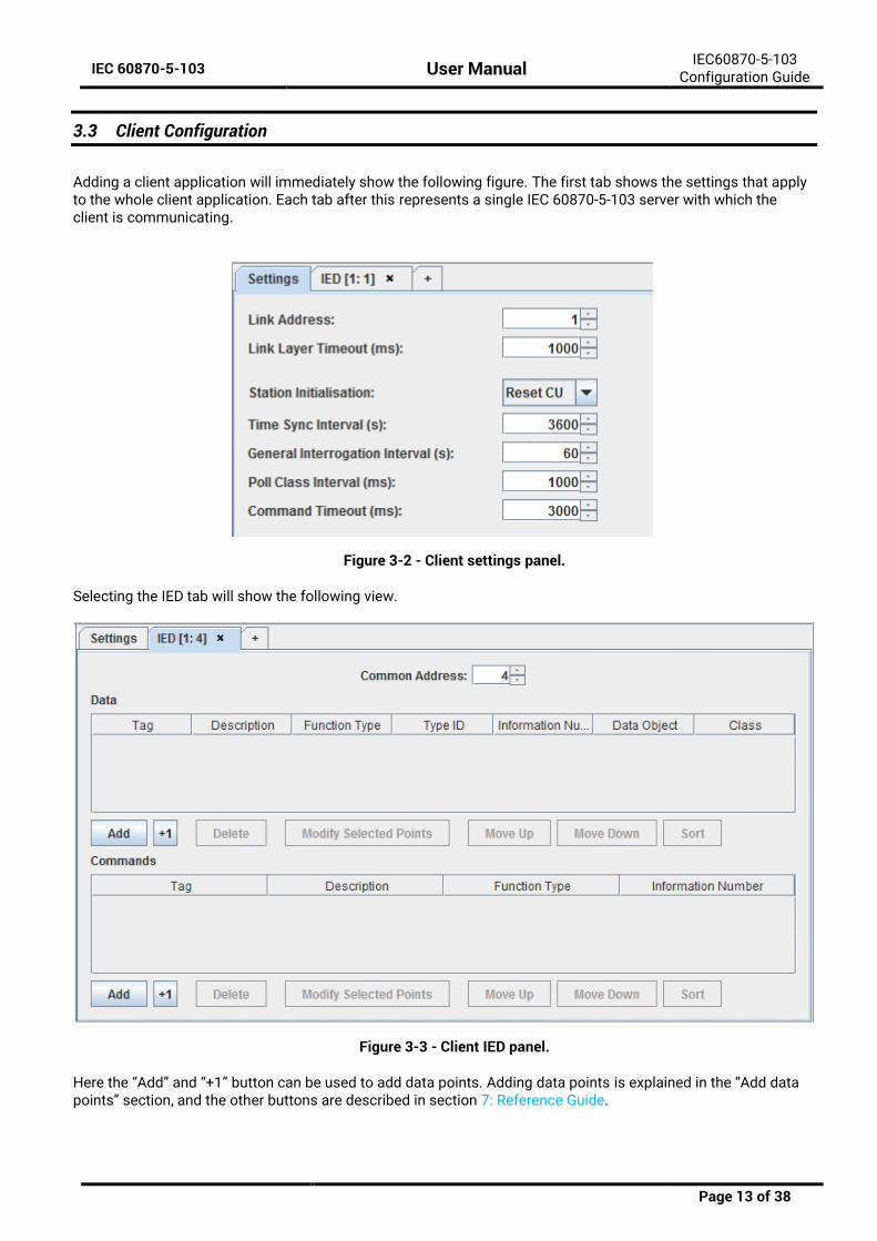
3.3 Client Configuration
Adding a client application will immediately show the following figure. The first tab shows the settings that apply to the whole client application. Each tab after this represents a single IEC 60870-5-103 server with which the client is communicating.
Figure 3-2 - Client settings panel.
Selecting the IED tab will show the following view.
Figure 3-3 - Client IED panel.
Here the “Add” and “+1” button can be used to add data points. Adding data points is explained in the “Add data points” section, and the other buttons are described in section 7: Reference Guide.

IEC 60870-5-103 User Manual IEC60870-5-103 Configuration Guide
Page 14 of 38
3.3.1 Client Settings
Listed below are details about each client setting.
3.3.1.1 Link Address
Description The link address address to use.
Data Entry Integer
Range 0 to 255
Input Option Mandatory
3.3.1.2 Link Layer Timeout (ms)
Description The timeout for a data link layer confirmation in milliseconds.
Data Entry Integer
Range 100 to 65535
Input Option Mandatory
3.3.1.3 Station Initialisation
Description The option to use in the station initialisation (reset communications) command. CU = Communications unit, FCB = Frame count bit.
Data Entry Drop down menu
Options Reset CU, Reset FCB
Input Option Mandatory
3.3.1.4 Time Sync Interval (s)
Description The interval that the time synchronisation commands are sent, in seconds.
Data Entry Integer
Range 1 to 65535. Default: 3600
Input Option Mandatory
3.3.1.5 General Interrogation Interval (s)
Description The interval that general interrogation commands are sent, in seconds.
Data Entry Integer
Range 0 to 65535
Input Option Mandatory
3.3.1.6 Poll Class Interval (ms)
Description The interval at which the classes are polled, in milliseconds.
Data Entry Integer
Range 0 to 65535
Input Option Mandatory

IEC 60870-5-103 User Manual IEC60870-5-103 Configuration Guide
Page 15 of 38
3.3.1.7 Command Timeout (ms)
Description The timeout to wait for a command to complete, in milliseconds.
Data Entry Integer
Range 0 to 65535
Input Option Mandatory
IEC 60870-5-103 User Manual IEC60870-5-103 Configuration Guide
Page 16 of 38
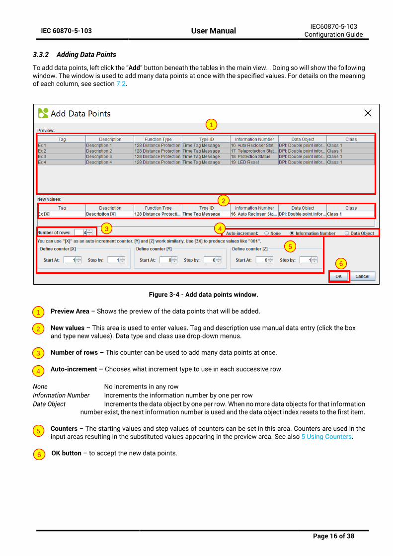
3.3.2 Adding Data Points
To add data points, left click the “Add” button beneath the tables in the main view. . Doing so will show the following window. The window is used to add many data points at once with the specified values. For details on the meaning of each column, see section 7.2.
Figure 3-4 - Add data points window.
Preview Area – Shows the preview of the data points that will be added.
New values – This area is used to enter values. Tag and description use manual data entry (click the box and type new values). Data type and class use drop-down menus.
Number of rows – This counter can be used to add many data points at once.
Auto-increment – Chooses what increment type to use in each successive row.
None No increments in any row
Information Number Increments the information number by one per row
Data Object Increments the data object by one per row. When no more data objects for that information number exist, the next information number is used and the data object index resets to the first item.
Counters – The starting values and step values of counters can be set in this area. Counters are used in the input areas resulting in the substituted values appearing in the preview area. See also 5 Using Counters.
OK button – to accept the new data points.
1
2
3
5
4
6
1
2
3
4
5
6
IEC 60870-5-103 User Manual IEC60870-5-103 Configuration Guide
Page 17 of 38
3.3.2.1 Add a Single Data Point
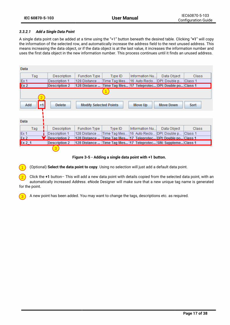
A single data point can be added at a time using the “+1” button beneath the desired table. Clicking “+1” will copy the information of the selected row, and automatically increase the address field to the next unused address. This means increasing the data object, or if the data object is at the last value, it increases the information number and uses the first data object in the new information number. This process continues until it finds an unused address.
Figure 3-5 - Adding a single data point with +1 button.
(Optional) Select the data point to copy. Using no selection will just add a default data point.
Click the +1 button– This will add a new data point with details copied from the selected data point, with an
automatically increased Address. eNode Designer will make sure that a new unique tag name is generated for the point.
A new point has been added. You may want to change the tags, descriptions etc. as required.
1
2
3
1
2
3
IEC 60870-5-103 User Manual IEC60870-5-103 Configuration Guide
Page 18 of 38
3.3.3 Connected Servers (Remote IEDs)
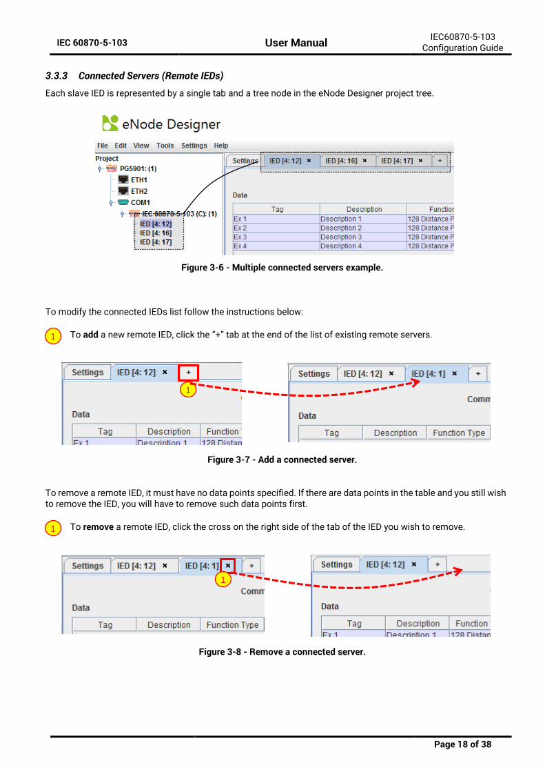
Each slave IED is represented by a single tab and a tree node in the eNode Designer project tree.
Figure 3-6 - Multiple connected servers example.
To modify the connected IEDs list follow the instructions below:
To add a new remote IED, click the “+” tab at the end of the list of existing remote servers.
Figure 3-7 - Add a connected server.
To remove a remote IED, it must have no data points specified. If there are data points in the table and you still wish to remove the IED, you will have to remove such data points first.
To remove a remote IED, click the cross on the right side of the tab of the IED you wish to remove.
Figure 3-8 - Remove a connected server.
1
1
1
1
IEC 60870-5-103 User Manual IEC60870-5-103 Configuration Guide
Page 19 of 38
3.4 Server Configuration
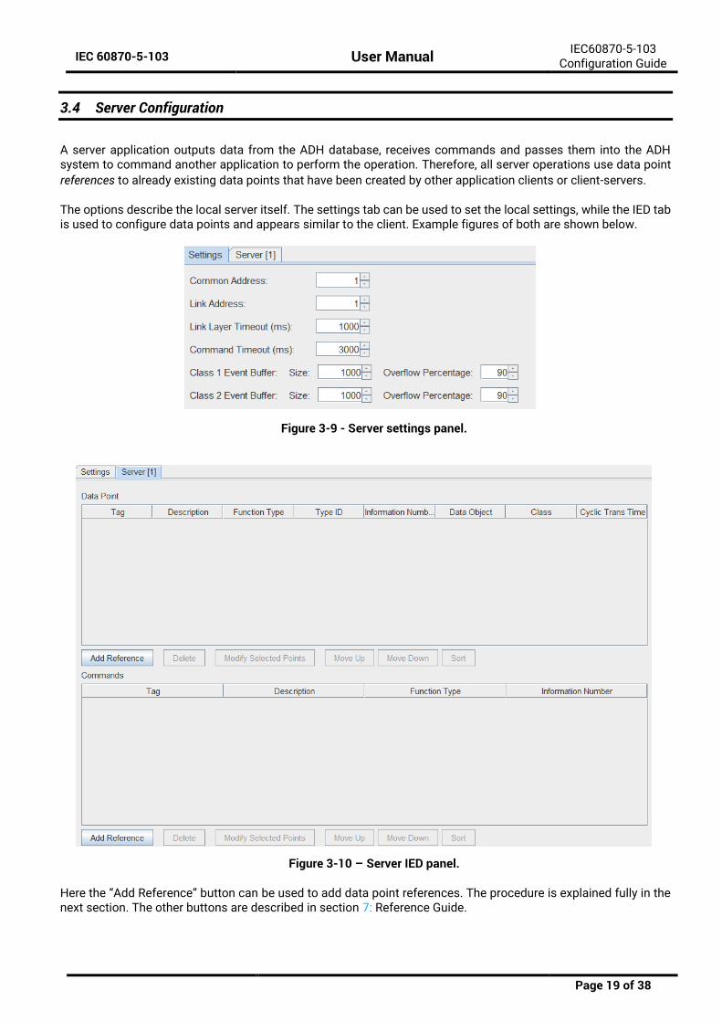
A server application outputs data from the ADH database, receives commands and passes them into the ADH system to command another application to perform the operation. Therefore, all server operations use data point
references to already existing data points that have been created by other application clients or client-servers. The options describe the local server itself. The settings tab can be used to set the local settings, while the IED tab is used to configure data points and appears similar to the client. Example figures of both are shown below.
Figure 3-9 - Server settings panel.
Figure 3-10 – Server IED panel.
Here the “Add Reference” button can be used to add data point references. The procedure is explained fully in the next section. The other buttons are described in section 7: Reference Guide.
IEC 60870-5-103 User Manual IEC60870-5-103 Configuration Guide
Page 20 of 38
3.4.1 Server Settings
All server settings are explained in the headings below.
3.4.1.1 Link Address
Description The link address to use.
Data Entry Integer
Range 0 to 255 (default 1)
Input Option Mandatory
3.4.1.2 Common Address
Description The common address to use.
Data Entry Integer
Range 0 to 255 (default 1)
Input Option Mandatory
3.4.1.3 Link Layer Timeout (ms)
Description The timeout for a data link layer confirmation in milliseconds.
Data Entry Integer
Range 100 to 65535 (default 1000)
Input Option Mandatory
3.4.1.4 Command Timeout (ms)
Description The timeout for a command in milliseconds.
Data Entry Integer
Range 100 to 10000 (default 3000)
Input Option Mandatory
3.4.1.5 Class {X} Event Buffer Size
Description The buffer size for class {X}: the maximum number of events to store.
Data Entry Integer
Range 0 - 65535
Input Option Mandatory
3.4.1.6 Class {X} Event Buffer Overflow Percentage
Description If the buffer for class {X} fills to this percent full, a buffer overflow event is sent to the master station.
Data Entry Integer
Range 0-100. Recommended 50-95. Default: 90
Input Option Mandatory
IEC 60870-5-103 User Manual IEC60870-5-103 Configuration Guide
Page 21 of 38
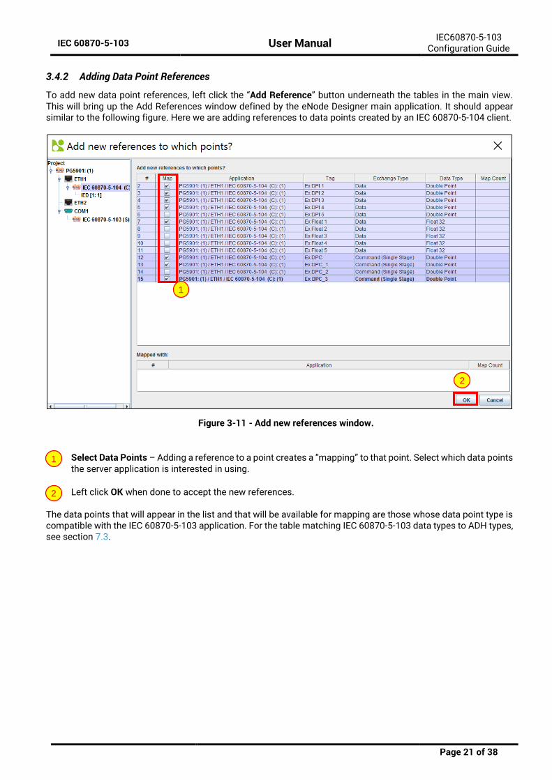
3.4.2 Adding Data Point References
To add new data point references, left click the “Add Reference” button underneath the tables in the main view. This will bring up the Add References window defined by the eNode Designer main application. It should appear similar to the following figure. Here we are adding references to data points created by an IEC 60870-5-104 client.
Figure 3-11 - Add new references window.
Select Data Points – Adding a reference to a point creates a “mapping” to that point. Select which data points the server application is interested in using.
Left click OK when done to accept the new references.
The data points that will appear in the list and that will be available for mapping are those whose data point type is compatible with the IEC 60870-5-103 application. For the table matching IEC 60870-5-103 data types to ADH types, see section 7.3.
1
2
1
2
IEC 60870-5-103 User Manual IEC60870-5-103 Configuration Guide
Page 22 of 38
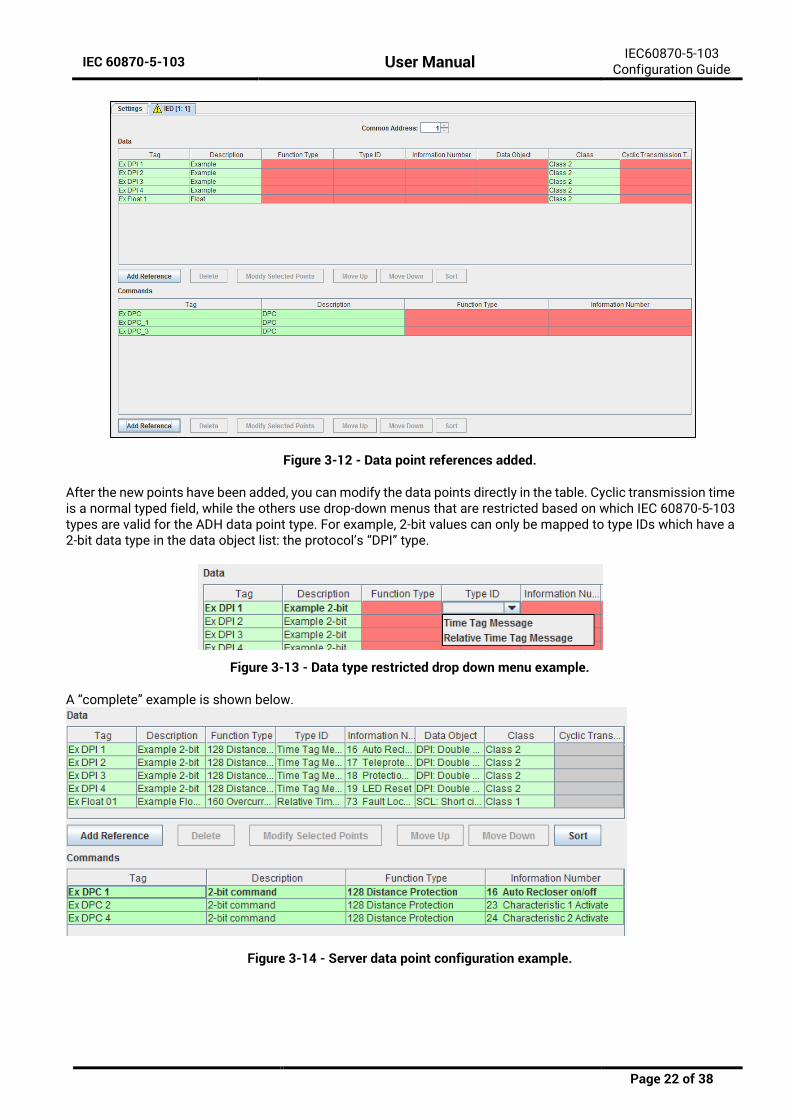
Figure 3-12 - Data point references added.
After the new points have been added, you can modify the data points directly in the table. Cyclic transmission time is a normal typed field, while the others use drop-down menus that are restricted based on which IEC 60870-5-103 types are valid for the ADH data point type. For example, 2-bit values can only be mapped to type IDs which have a 2-bit data type in the data object list: the protocol’s “DPI” type.
Figure 3-13 - Data type restricted drop down menu example.
A “complete” example is shown below.
Figure 3-14 - Server data point configuration example.

IEC 60870-5-103 User Manual IEC60870-5-103 Configuration Guide
Page 23 of 38
3.5 Miscellaneous Common
3.5.1 Incomplete, Conflicting and not needed Information
Incomplete or conflicting information is shown in red. This will cause warning symbols on the tab and in the project tree. Hovering over the warning icons will show further details about what is causing the warning. This allows the user to quickly fix invalid information.
Figure 3-15 – Incomplete and missing information example.
Mouse-over a warning to show a tooltip explaining the warning.
Invalid data shows in red. The dark red color means the data is invalid, and the light red color means there is an address conflict.
Unneeded data is hidden and not editable. For example, the Cyclic transmission time is only used for Measurand types. So, non-measurand points have these table cells with a grey background, have no contents
and cannot be edited.
2
3
1
2
3
IEC 60870-5-103 User Manual IEC60870-5-103 Configuration Guide
Page 24 of 38
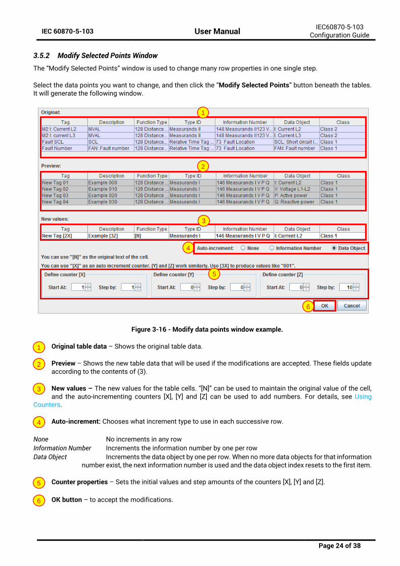
3.5.2 Modify Selected Points Window
The “Modify Selected Points” window is used to change many row properties in one single step.
Select the data points you want to change, and then click the “Modify Selected Points” button beneath the tables. It will generate the following window.
Figure 3-16 - Modify data points window example.
Original table data – Shows the original table data.
Preview – Shows the new table data that will be used if the modifications are accepted. These fields update according to the contents of (3).
New values – The new values for the table cells. “[N]” can be used to maintain the original value of the cell, and the auto-incrementing counters [X], [Y] and [Z] can be used to add numbers. For details, see Using
Counters.
Auto-increment: Chooses what increment type to use in each successive row.
None No increments in any row
Information Number Increments the information number by one per row
Data Object Increments the data object by one per row. When no more data objects for that information number exist, the next information number is used and the data object index resets to the first item.
Counter properties – Sets the initial values and step amounts of the counters [X], [Y] and [Z].
OK button – to accept the modifications.
1
2
3
4
5
6
1
2
3
4
5
6
IEC 60870-5-103 User Manual Communication Port Properties
Page 25 of 38
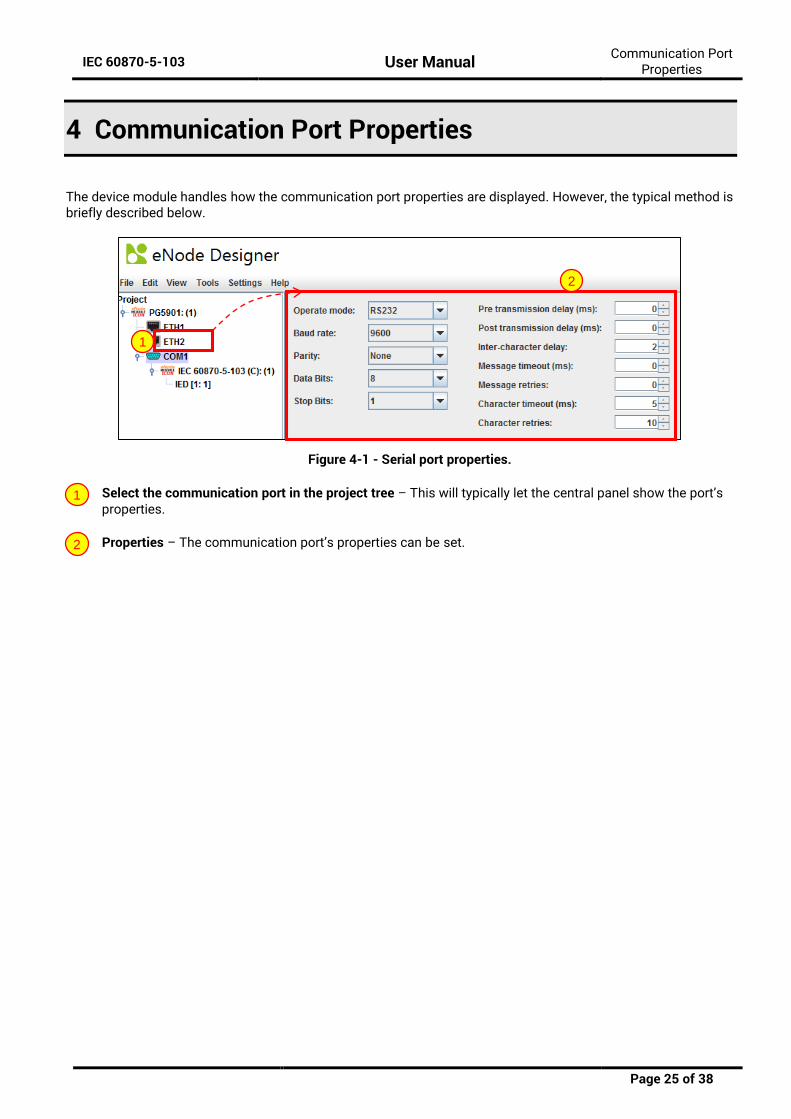
4 Communication Port Properties
The device module handles how the communication port properties are displayed. However, the typical method is briefly described below.
Figure 4-1 - Serial port properties.
Select the communication port in the project tree – This will typically let the central panel show the port’s properties.
Properties – The communication port’s properties can be set.
1
2
1
2
IEC 60870-5-103 User Manual Using Counters
Page 26 of 38
5 Using Counters
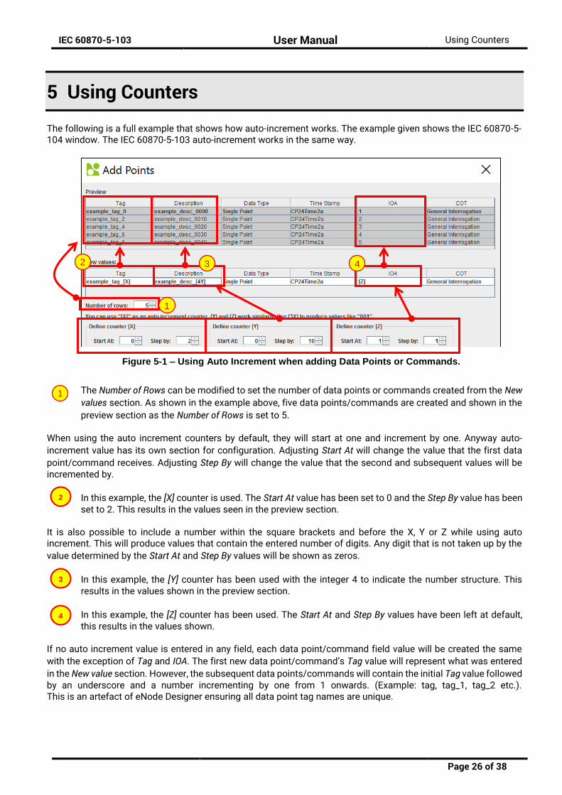
The following is a full example that shows how auto-increment works. The example given shows the IEC 60870-5-104 window. The IEC 60870-5-103 auto-increment works in the same way.
The Number of Rows can be modified to set the number of data points or commands created from the New values section. As shown in the example above, five data points/commands are created and shown in the
preview section as the Number of Rows is set to 5.
When using the auto increment counters by default, they will start at one and increment by one. Anyway auto-
increment value has its own section for configuration. Adjusting Start At will change the value that the first data
point/command receives. Adjusting Step By will change the value that the second and subsequent values will be incremented by.
In this example, the [X] counter is used. The Start At value has been set to 0 and the Step By value has been set to 2. This results in the values seen in the preview section.
It is also possible to include a number within the square brackets and before the X, Y or Z while using auto increment. This will produce values that contain the entered number of digits. Any digit that is not taken up by the
value determined by the Start At and Step By values will be shown as zeros.
In this example, the [Y] counter has been used with the integer 4 to indicate the number structure. This results in the values shown in the preview section.
In this example, the [Z] counter has been used. The Start At and Step By values have been left at default, this results in the values shown.
If no auto increment value is entered in any field, each data point/command field value will be created the same
with the exception of Tag and IOA. The first new data point/command’s Tag value will represent what was entered
in the New value section. However, the subsequent data points/commands will contain the initial Tag value followed by an underscore and a number incrementing by one from 1 onwards. (Example: tag, tag_1, tag_2 etc.). This is an artefact of eNode Designer ensuring all data point tag names are unique.
2
4
3
1
Figure 5-1 – Using Auto Increment when adding Data Points or Commands.
1
2 3 4
IEC 60870-5-103 User Manual Interoperability
Page 27 of 38
6 Interoperability
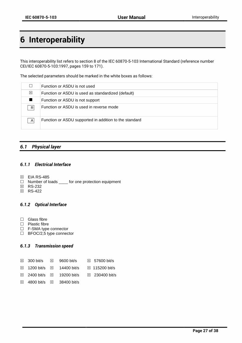
This interoperability list refers to section 8 of the IEC 60870-5-103 International Standard (reference number CEI/IEC 60870-5-103:1997, pages 159 to 171). The selected parameters should be marked in the white boxes as follows:
Function or ASDU is not used
Function or ASDU is used as standardized (default)
Function or ASDU is not support
Function or ASDU is used in reverse mode
Function or ASDU supported in addition to the standard
6.1 Physical layer
6.1.1 Electrical Interface
EIA RS-485Number of loads ____ for one protection equipmentRS-232RS-422
6.1.2 Optical Interface
Glass fibrePlastic fibreF-SMA type connectorBFOC/2,5 type connector
6.1.3 Transmission speed
300 bit/s 9600 bit/s 57600 bit/s
1200 bit/s 14400 bit/s 115200 bit/s
2400 bit/s 19200 bit/s 230400 bit/s
4800 bit/s 38400 bit/s
R
A
IEC 60870-5-103 User Manual Interoperability
Page 28 of 38
6.2 Link Layer
There are no choices for the link layer.
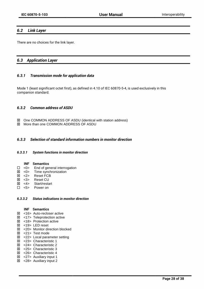
6.3 Application Layer
6.3.1 Transmission mode for application data
Mode 1 (least significant octet first), as defined in 4.10 of IEC 60870-5-4, is used exclusively in this companion standard.
6.3.2 Common address of ASDU
One COMMON ADDRESS OF ASDU (identical with station address)More than one COMMON ADDRESS OF ASDU
6.3.3 Selection of standard information numbers in monitor direction
6.3.3.1 System functions in monitor direction
INF Semantics <0> End of general interrogation<0> Time synchronization<2> Reset FCB<3> Reset CU<4> Start/restart<5> Power on
6.3.3.2 Status indications in monitor direction
INF Semantics <16> Auto-recloser active<17> Teleprotection active<18> Protection active<19> LED reset<20> Monitor direction blocked<21> Test mode<22> Local parameter setting<23> Characteristic 1<24> Characteristic 2<25> Characteristic 3<26> Characteristic 4<27> Auxiliary input 1<28> Auxiliary input 2

IEC 60870-5-103 User Manual Interoperability
Page 29 of 38
<29> Auxiliary input 3<30> Auxiliary input 4
6.3.3.3 Supervision indications in monitor direction
INF Semantics <32> Measurand supervision I<33> Measurand supervision V<35> Phase sequence supervision<36> Trip circuit supervision<37> I>> back-up operation<38> VT fuse failure<39> Teleprotection disturbed<46> Group warning<47> Group alarm
6.3.3.4 Earth fault indications in monitor direction
INF Semantics <48> Earth fault L1<49> Earth fault L2<50> Earth fault L3<51> Earth fault forward, i.e. line<52> Earth fault reverse, i.e. busbar
6.3.3.5 Fault indications in monitor direction
INF Semantics <64> Start /pick-up L1<65> Start /pick-up L2<66> Start /pick-up L3<67> Start /pick-up N<68> General trip<69> Trip L1<70> Trip L2<71> Trip L3<72> Trip I>> (back-up operation)<73> Fault location X in ohms<74> Fault forward/line<75> Fault reverse/busbar<76> Teleprotection signal transmitted<77> Teleprotection signal received<78> Zone 1<79> Zone 2<80> Zone 3<81> Zone 4<82> Zone 5<83> Zone 6<84> General start/pick-up<85> Breaker failure<86> Trip measuring system L1<87> Trip measuring system L2<88> Trip measuring system L3<89> Trip measuring system E<90> Trip I>

IEC 60870-5-103 User Manual Interoperability
Page 30 of 38
<91> Trip I>><92> Trip IN><93> Trip IN>>
6.3.3.6 Auto-reclosure indications in monitor direction
INF Semantics <128> CB ‘on’ by AR<129> CB ‘on’ by long-time AR<130> AR blocked
6.3.3.7 Measurands in monitor direction
INF Semantics <144> Measurand I<145> Measurands I, V<146> Measurands I, V, P, Q<147> Measurands IN, VEN<148> Measurands IL1,2,3, VL1,2,3, P, Q, f
6.3.3.8 Generic functions in monitor direction
INF Semantics <240> Read headings of all defined groups<241> Read values or attributes of all entries of one group<243> Read directory of a single entry<244> Read value or attribute of a single entry<245> End of general interrogation of generic data<249> Write entry with confirmation<250> Write entry with execution<251> Write entry aborted
6.3.4 Selection of standard information numbers in control direction
6.3.4.1 System functions in control direction
INF Semantics <0> Initiation of general interrogation<0> Time synchronization
6.3.4.2 General commands in control direction
INF Semantics <16> Auto-recloser on/off<17> Teleprotection on/off<18> Protection on/off<19> LED reset<23> Activate characteristic 1
IEC 60870-5-103 User Manual Interoperability
Page 31 of 38
<24> Activate characteristic 2<25> Activate characteristic 3<26> Activate characteristic 4
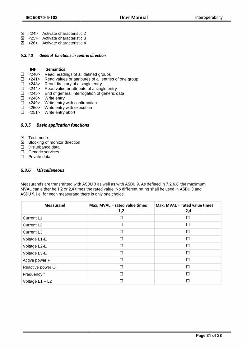
6.3.4.3 General functions in control direction
INF Semantics <240> Read headings of all defined groups<241> Read values or attributes of all entries of one group<243> Read directory of a single entry<244> Read value or attribute of a single entry<245> End of general interrogation of generic data<248> Write entry<249> Write entry with confirmation<250> Write entry with execution<251> Write entry abort
6.3.5 Basic application functions
Test modeBlocking of monitor directionDisturbance dataGeneric servicesPrivate data
6.3.6 Miscellaneous
Measurands are transmitted with ASDU 3 as well as with ASDU 9. As defined in 7.2.6.8, the maximum MVAL can either be 1,2 or 2,4 times the rated value. No different rating shall be used in ASDU 3 and ASDU 9, i.e. for each measurand there is only one choice.
Measurand Max. MVAL = rated value times 1,2
Max. MVAL = rated value times 2,4
Current L1
Current L2
Current L3
Voltage L1-E
Voltage L2-E
Voltage L3-E
Active power P
Reactive power Q
Frequency f
Voltage L1 – L2
IEC 60870-5-103 User Manual Reference Guide
Page 32 of 38
7 Reference Guide
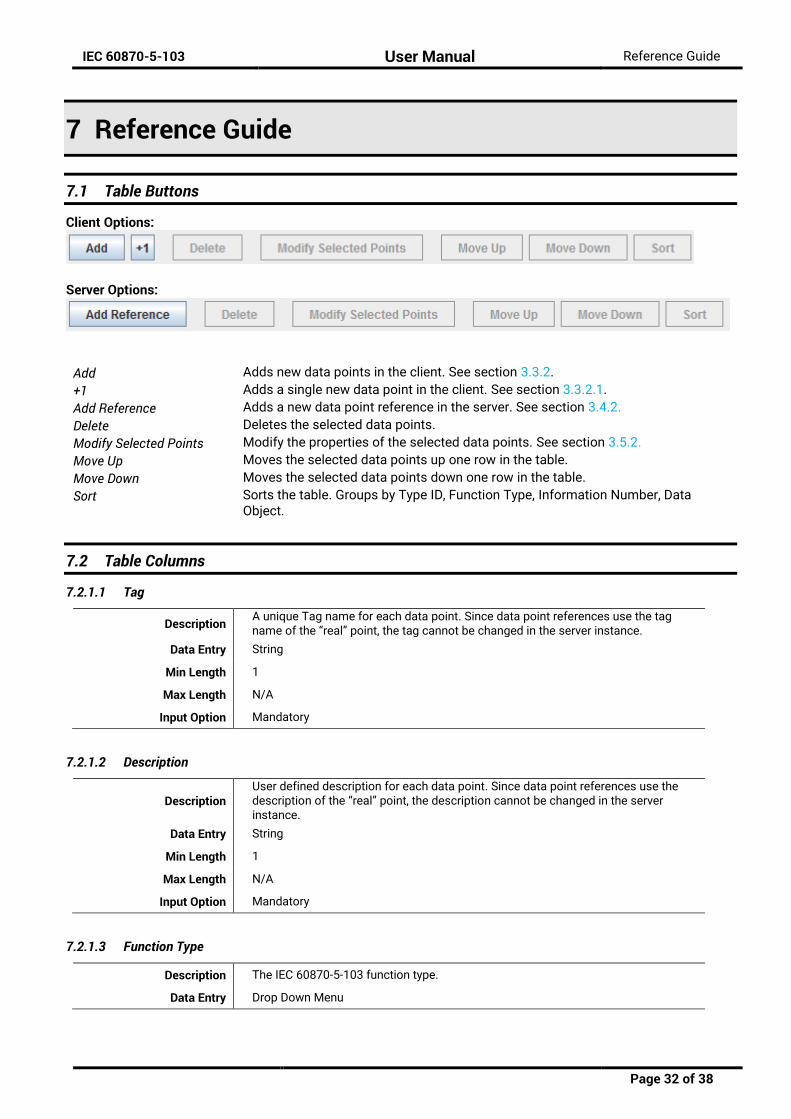
7.1 Table Buttons
Client Options:
Server Options:
Add Adds new data points in the client. See section 3.3.2.
+1 Adds a single new data point in the client. See section 3.3.2.1.
Add Reference Adds a new data point reference in the server. See section 3.4.2.
Delete Deletes the selected data points.
Modify Selected Points Modify the properties of the selected data points. See section 3.5.2.
Move Up Moves the selected data points up one row in the table.
Move Down Moves the selected data points down one row in the table.
Sort Sorts the table. Groups by Type ID, Function Type, Information Number, Data Object.
7.2 Table Columns
7.2.1.1 Tag
Description A unique Tag name for each data point. Since data point references use the tag name of the “real” point, the tag cannot be changed in the server instance.
Data Entry String
Min Length 1
Max Length N/A
Input Option Mandatory
7.2.1.2 Description
Description User defined description for each data point. Since data point references use the description of the “real” point, the description cannot be changed in the server instance.
Data Entry String
Min Length 1
Max Length N/A
Input Option Mandatory
7.2.1.3 Function Type
Description The IEC 60870-5-103 function type.
Data Entry Drop Down Menu

IEC 60870-5-103 User Manual Reference Guide
Page 33 of 38
Types
128 Distance Protection 160 Overcurrent Protection 176 Transformer Differential Protection 192 Line Differential Protection 254 Generic Function Type 255 Global Function Type
Input Option Mandatory
7.2.1.4 Type ID
Description The IEC 60870-5-103 Type ID. This can be used to restrict the available items in shown in the “Information Number” menu.
Data Entry Drop Down Menu
Types
Time Tag Message Relative Time Tag Message Measurands I Relative Time Tag Measurands Identification Measurands II
Input Option Mandatory
7.2.1.5 Information Number
Description The IEC 60870-5-103 information number. The drop down menus will only show relevant information numbers for the data point (usually, just shows information numbers with the given type ID).
Data Entry Drop Down Menu
Types
=========== Data =========== 2 Info Reset FCB 3 Info Reset CU 4 Info Start Restart 5 Info Power On 16 Auto Recloser Status 17 Tele Protection Status 18 Protection Status 19 Led Reset 20 Monitor Direction Blocked 21 Test Mode Info 22 Local Parameter Setting 23 Characteristic 1 24 Characteristic 2 25 Characteristic 3 26 Characteristic 4 27 Auxiliary Input 1 28 Auxiliary Input 2 29 Auxiliary Input 3 30 Auxiliary Input 4 32 Measurand Supervision I 33 Measurand Supervision V 35 Phase Sequence Supervision 36 Trip Circuit Supervision 37 Over I Backup Operation

IEC 60870-5-103 User Manual Reference Guide
Page 34 of 38
38 Vt Fuse Failure 39 Teleprotection Disturbed 46 Group Warning 47 Group Alarm 48 Earth Fault L1 49 Earth Fault L2 50 Earth Fault L3 51 Earth Fault Forward 52 Earth Fault Reverse 64 Start Pickup L1 65 Start Pickup L2 66 Start Pickup L3 67 Start Pickup N 68 General Trip 69 Trip L1 70 Trip L2 71 Trip L3 72 Trip Over I Backup 73 Fault Location 74 Fault Forward 75 Fault Reverse 76 Teleprotection Signal Transmitted 77 Teleprotection Signal Received 78 Zone 1 79 Zone 2 80 Zone 3 81 Zone 4 82 Zone 5 83 Zone 6 84 General Start Pickup 85 Breaker Failure 86 Trip Measuring System L1 87 Trip Measuring System L2 88 Trip Measuring System L3 89 Trip Measuring System E 90 Trip I 91 Trip Over I 92 Trip In 93 Trip Over In 128 CB On By AR 129 CB On By Long Time AR 130 Auto Recloser Blocked 144 Measurand I 145 Measurands I V 146 Measurands I V P Q 147 Measurands In Ven 148 Measurands Il123 Vl123 P Q F =========== Commands =========== 16 Auto Recloser on/off 17 Teleprotection on/off 18 Protection on/off 19 LED Reset 23 Characteristic 1 Activate 24 Characteristic 2 Activate 25 Characteristic 3 Activate 26 Characteristic 4 Activate

IEC 60870-5-103 User Manual Reference Guide
Page 35 of 38
Input Option Mandatory
IEC 60870-5-103 User Manual Reference Guide
Page 36 of 38
7.2.1.6 Data Object
Description
The IEC 60870-5-103 data object instance of the information number. The drop down menus will only show data objects relevant to the data point. Usually, this means it will show the data objects given the information number / type ID. Though in application servers, the ADH data point type must also match for it to appear in the list.
Data Entry Drop Down Menu
Types
DPI: Double point information SIN: Supplementary information COL: Compatibility level SCL: Short circuit location FAN: Fault number RET: Relative time =========== MVAL (Measurand values) =========== I: Current I_N I: Current L1 I: Current L2 I: Current L3 V: Voltage V_EN V: Voltage L1-L2 V: Voltage L1-E V: Voltage L2-E V: Voltage L3-E P: Active power Q: Reactive power f: Frequency
Input Option Mandatory
7.2.1.7 Class
Data only
Description The IEC 60870-5-103 class.
Data Entry Drop down menu
Options Class 1, Class 2
Input Option Mandatory
7.2.1.8 Cyclic Transmission Time (s)
Server, data only
Description Every “cyclic transmission time” amount of time, the Measurand values are sent back to the client. Measured in seconds.
Data Entry Integer
Types 0 to 65535
Input Option Mandatory for Measurand types only

IEC 60870-5-103 User Manual Reference Guide
Page 37 of 38
7.3 IEC 60870-5-103’s Related ADH Types
The IEC 60870-5-103 data types correspond to the ADH types given in the table below.
IEC 60870-5-103 Point Type ADH Data Type ADH Exchange Type COL: Compatibility level Unsigned 8 Data
DCO: Double point command Double Point Command (Single Stage)
DPI: Double point information Double Point Data
FAN: Fault number Unsigned 16 Data
MVAL: Measurand value Integer 16 Data
RET: Relative time Unsigned 16 Data
SCL: Short circuit location Float 32 Data
SIN: Supplementary information Unsigned 8 Data
Table 7-1 – IEC 60870-5-103 data types relation to ADH data point types.

IEC 60870-5-103 User Manual Reference Guide
Page 38 of 38
Atop Technologies, Inc.
www.atoponline.com www.atop.com.tw
TAIWAN HEADQUARTER: 2F, No. 146, Sec. 1, Tung-Hsing Rd, 30261 Chupei City, Hsinchu County Taiwan, R.O.C. Tel: +886-3-550-8137 Fax: +886-3-550-8131
ATOP CHINA BRANCH:
3F, 75th, No. 1066 Building, Qingzhou North Road, Shanghai, China Tel: +86-21-64956231
ATOP INDIA OFFICE: Abhishek Srivastava Head of India Sales Atop Communication Solution(P) Ltd. No. 22, Kensington Terrace, Kensington Rd, Bangalore, 560008, India Tel: +91-80-4920-6363 E-mail: [email protected]
ATOP INDONESIA BRANCH: Jopson Li Branch Director Wisma Lampung Jl. No. 40, Tomang Raya Jakarta, Barat, 11430, Indonesia Tel: +62-857-10595775 E-mail: [email protected]
ATOP EMEA OFFICE:
Bhaskar Kailas (BK) Vice President (Business Development) Atop Communication Solution(P) Ltd. No. 22, Kensington Terrace, Kensington Rd, Bangalore, 560008, India Tel: +91-988-0788-559 E-mail: [email protected]
ATOP AMERICAs OFFICE: Venke Char Sr. Vice President & Head of Business 11811 North Tatum Blvd, Suite 3031 Phoenix, AZ 85028, United States Tel: +1-602-953-7669 E-mail: [email protected]


![Dynamic Host Configuration Protocol DHCP [RFC 2131 - 1997 ] · 2016-12-04 · Dynamic Host Configuration Protocol DHCP [RFC 2131 - 1997 ] 2 ... Source Destination Protocol Info 0.0.0.0](https://static.fdocuments.fr/doc/165x107/5f4bcafcc73ffb6385247ba9/dynamic-host-configuration-protocol-dhcp-rfc-2131-1997-2016-12-04-dynamic.jpg)