
Power Factor Control in a Wind Energy Conversion System via Synchronous Generator Excitation
6
CANADIAN JOURNAL OF ELECTRICAL AND COMPUTER ENGINEERING, VOL. 37, NO. 3, SUMMER 2014 145 Power Factor Control in a Wind Energy Conversion System via Synchronous Generator Excitation Contrôle du facteur de puissance dans un système de conversion de l’énergie éolienne par excitation synchrone du générateur Murad Jafari, Member, IEEE, Miteshkumar Popat, Member, IEEE, and Bin Wu, Fellow, IEEE Abstract—This paper proposes a novel control technique to improve the power factor over a wide range of wind speeds in a wind energy conversion system (WECS) using a current source inverter (CSI) and an electrically excited synchronous generator. The system consists of diode rectifier on the generator side, while a pulsewidth modulated CSI is on the grid side. In the proposed control scheme, the generator excitation is controlled with the wind speed to improve the grid power factor, while the control freedoms of the CSI are used to regulate the power output of the WECS to meet maximum power point tracking of wind energy. Theoretical analysis is conducted to investigate the feasibility and limits of this approach. The simulation model for the proposed WECS is developed, and the simulation results confirm the validity of the theoretical analysis. With the proposed power factor control scheme, improvements of grid-side power factor are achieved over a wider range of wind speeds. Résumé—Cet article propose une nouvelle technique de contrôle pour améliorer le facteur de puissance sur une large gamme de vitesses de vent dans un système de conversion de l’énergie éolienne (SCEE) à l’aide d’un inverseur de source de courant (ISC) et d’un générateur synchronisé à excitation électrique. Le système est constitué d’un redresseur à diode du côté du générateur et d’une largeur d’impulsion modulée ISC du côté de la grille. Dans le schéma de contrôle proposé, l’excitation du générateur est contrôlée par la vitesse du vent pour améliorer le facteur de puissance de la grille, tandis que le contrôle de l’ISC est utilisé pour réguler la puissance de sortie du SCEE afin d’assurer un maximum de suivi de la puissance et les limites de l’énergie éolienne. L’analyse théorique est menée afin d’évaluer la faisabilité et les limites de cette approche. Le modèle de simulation pour le SCEE proposé a été développé et les résultats de simulation confirment la validité de l’analyse théorique. Avec le système de contrôle de facteur de puissance proposée, des améliorations du facteur de puissance côté réseau ont été atteints sur une plus large gamme de vitesses de vent. Index Terms—Current-source converter, electrically excited synchronous generator (EESG), power factor, wind energy. I. I NTRODUCTION T HE current-source converter (CSC)-based wind energy conversion system (WECS) offers distinct advantages that include, among others, simple topologies, good grid-side waveforms, and protection against short circuit due to the high inductance in the dc choke [1]. Previous research was done on several possible topologies that would meet grid requirements in terms of support for grid voltage and frequency as well as fault ride through. However, since wind speed is not constant, the system must be able to extract the maximum possible energy from the wind [maximum power point tracking (MPPT)] as well as meet the Manuscript received November 29, 2013; accepted May 18, 2014. Date of current version October 15, 2014. The authors are with the Department of Electrical and Computer Engi- neering, Ryerson University, Toronto, ON M5B 2K3, Canada (e-mail: [email protected]; [email protected]; [email protected]). Associate Editor managing this paper’s review: Davood Yazdani. Color versions of one or more of the figures in this paper are available online at http://ieeexplore.ieee.org. Digital Object Identifier 10.1109/CJECE.2014.2327951 power factor expectations within the maximum possible range of wind speed [2]–[6]. In [2] and [3], the CSC-based systems primarily consisted of a permanent magnet synchronous generator (PMSG) con- nected with a pulsewidth modulated (PWM) CSR on the generator side and a PWM current source inverter (CSI) on the grid side. The two PWM CSCs have enough control freedoms to allow for controlling both the output active power and keeping the dc current at the level needed to maintain the required output power factor. A topology based on a diode rectifier and a buck converter instead of the PWM CSR was also suggested to achieve the same objective [4]. The buck converter served to boost the dc link current level, such that the power factor is maintained, which decouples the grid- side dc-link current requirement from the generator-side out- put.In [5], the back-to-back thyristor converter for synchronous generator-based WECS is investigated. Compared with the topology in [4], it replaces the generator-side diode rectifier with a thyristor rectifier and obtained additional control free- dom. However, the filters and compensator are still necessary 0840-8688 © 2014 IEEE. Personal use is permitted, but republication/redistribution requires IEEE permission. See http://www.ieee.org/publications_standards/publications/rights/index.html for more information.
Transcript of Power Factor Control in a Wind Energy Conversion System via Synchronous Generator Excitation
CANADIAN JOURNAL OF ELECTRICAL AND COMPUTER ENGINEERING, VOL. 37, NO. 3, SUMMER 2014 145
Power Factor Control in a Wind Energy ConversionSystem via Synchronous Generator Excitation
Contrôle du facteur de puissance dans un systèmede conversion de l’énergie éolienne par excitation
synchrone du générateurMurad Jafari, Member, IEEE, Miteshkumar Popat, Member, IEEE, and Bin Wu, Fellow, IEEE
Abstract— This paper proposes a novel control technique to improve the power factor over a wide rangeof wind speeds in a wind energy conversion system (WECS) using a current source inverter (CSI) and anelectrically excited synchronous generator. The system consists of diode rectifier on the generator side, whilea pulsewidth modulated CSI is on the grid side. In the proposed control scheme, the generator excitation iscontrolled with the wind speed to improve the grid power factor, while the control freedoms of the CSI are usedto regulate the power output of the WECS to meet maximum power point tracking of wind energy. Theoreticalanalysis is conducted to investigate the feasibility and limits of this approach. The simulation model for theproposed WECS is developed, and the simulation results confirm the validity of the theoretical analysis. Withthe proposed power factor control scheme, improvements of grid-side power factor are achieved over a widerrange of wind speeds.
Résumé— Cet article propose une nouvelle technique de contrôle pour améliorer le facteur de puissance surune large gamme de vitesses de vent dans un système de conversion de l’énergie éolienne (SCEE) à l’aide d’uninverseur de source de courant (ISC) et d’un générateur synchronisé à excitation électrique. Le système estconstitué d’un redresseur à diode du côté du générateur et d’une largeur d’impulsion modulée ISC du côté dela grille. Dans le schéma de contrôle proposé, l’excitation du générateur est contrôlée par la vitesse du ventpour améliorer le facteur de puissance de la grille, tandis que le contrôle de l’ISC est utilisé pour réguler lapuissance de sortie du SCEE afin d’assurer un maximum de suivi de la puissance et les limites de l’énergieéolienne. L’analyse théorique est menée afin d’évaluer la faisabilité et les limites de cette approche. Le modèlede simulation pour le SCEE proposé a été développé et les résultats de simulation confirment la validité del’analyse théorique. Avec le système de contrôle de facteur de puissance proposée, des améliorations du facteurde puissance côté réseau ont été atteints sur une plus large gamme de vitesses de vent.
Index Terms— Current-source converter, electrically excited synchronous generator (EESG), power factor,wind energy.
I. INTRODUCTION
THE current-source converter (CSC)-based wind energyconversion system (WECS) offers distinct advantages
that include, among others, simple topologies, good grid-sidewaveforms, and protection against short circuit due to the highinductance in the dc choke [1].
Previous research was done on several possible topologiesthat would meet grid requirements in terms of support forgrid voltage and frequency as well as fault ride through.However, since wind speed is not constant, the system mustbe able to extract the maximum possible energy from the wind[maximum power point tracking (MPPT)] as well as meet the
Manuscript received November 29, 2013; accepted May 18, 2014. Date ofcurrent version October 15, 2014.
The authors are with the Department of Electrical and Computer Engi-neering, Ryerson University, Toronto, ON M5B 2K3, Canada (e-mail:[email protected]; [email protected]; [email protected]).
Associate Editor managing this paper’s review: Davood Yazdani.Color versions of one or more of the figures in this paper are available
online at http://ieeexplore.ieee.org.Digital Object Identifier 10.1109/CJECE.2014.2327951
power factor expectations within the maximum possible rangeof wind speed [2]–[6].
In [2] and [3], the CSC-based systems primarily consistedof a permanent magnet synchronous generator (PMSG) con-nected with a pulsewidth modulated (PWM) CSR on thegenerator side and a PWM current source inverter (CSI) on thegrid side. The two PWM CSCs have enough control freedomsto allow for controlling both the output active power andkeeping the dc current at the level needed to maintain therequired output power factor. A topology based on a dioderectifier and a buck converter instead of the PWM CSR wasalso suggested to achieve the same objective [4]. The buckconverter served to boost the dc link current level, such thatthe power factor is maintained, which decouples the grid-side dc-link current requirement from the generator-side out-put.In [5], the back-to-back thyristor converter for synchronousgenerator-based WECS is investigated. Compared with thetopology in [4], it replaces the generator-side diode rectifierwith a thyristor rectifier and obtained additional control free-dom. However, the filters and compensator are still necessary
0840-8688 © 2014 IEEE. Personal use is permitted, but republication/redistribution requires IEEE permission.See http://www.ieee.org/publications_standards/publications/rights/index.html for more information.

146 CANADIAN JOURNAL OF ELECTRICAL AND COMPUTER ENGINEERING, VOL. 37, NO. 3, SUMMER 2014
Fig. 1. Proposed system topology including an EESG, a diode rectifier, anda PWM CSI.
Fig. 2. MPPT power, torque, and generator speed versus wind speed [3].
to correct the WECS output for the grid-side converter. In[6], the topology with a diode rectifier on the generatorside and a multilevel CSI on the grid side was discussed.In [2]–[6], the PMSG-based WECS is considered. The electri-cally excited synchronous generator (EESG) is widely used inpractice; however, it has rarely been published in the previousliterature.
As shown in Fig. 1, the proposed system consists of a dioderectifier on the generator side and a PWM CSI on the gridside. The system proposed in this paper further simplifies thedesign by eliminating the buck converter and, instead, usesexcitation control of an EESG to control the dc-link currentlevel. Therefore, a low-cost and highly reliable diode rectifieron the generator side is preferred. The generator-side dioderectifier and grid-side PWM CSI are connected via a dc-linkchoke. Filter capacitors are parallel connected at both sidesto assist current commutation as well as filter out switchingharmonics [7], [8]. The grid-side CSI is normally connectedto the grid through a step-up transformer.
A main challenge for the proposed low-cost EESG-basedWECS shown in Fig. 1 is that it has a poor power factor duringlow wind speed conditions. In this paper, a novel controlscheme is proposed where generator excitation control is usedto improve the power factor at low wind speed.
II. GENERATOR-SIDE CONVERTER: DIODE RECTIFIER
Fig. 2 shows the maximum power that could be extractedat each wind speed is proportional to the cube of the windspeed, whereas the torque or dc-link current is proportional
Fig. 3. DC-link current requirements for diode rectifier with PWM CSI.
to the square of the wind speed [3]. For a fixed outputpower that corresponds to the maximum power at eachwind speed, the dc-link current value will vary dependingon excitation. At lower excitation, the output voltage drops,and consequently, the current increases.
In a diode rectifier, due to the large inductance of thegenerator, current commutation is not instantaneous and thecommutation angle depends on the back emf in the generator.The generator inductance as well as the dc-link current [9] canbe explained by
δ = cos−1
(1 −
√2ωg IdcLs
Eg,LL
)(1)
where ωg = 2πf = 377 rad/s, and Ls is the synchronousinductance. The diode commutation results in a voltage dropin the dc link [9]. The voltage drop mainly depends on thegenerator inductance and the dc current
Vdc = 1.35VLL − 3
πωLs Idc. (2)
Remembering that Pdc = Vdc Idc, we can substitute for Vdc =Pdc/Idc and solve for Idc.
The result is the following quadratic equation:
− 3
πωLs I 2
dc + 3√
2
πELL Idc − Pdc = 0. (3)
The solution for this equation is in the form of
Idc = K1 ± √K 2
2K3(4)
where K1 = 3√
2/π ELL, K2 = (3√
2/π ELL)2−12/πωLs Pdc,
and K3 = 6/πωLs .The first solution where Idc = (K1 + √
K 2)/2K3 is rejectedsince it results in unreasonably high values of the dc current.To achieve a real value of the dc current, ≥ K2 should be ≥ 0or (
3√
2
πELL
)2
≥ 12
πωLs Pdc. (5)
Both ELL and Pdc depend on wind speed. ELL also dependson excitation [10].
JAFARI et al.: POWER FACTOR CONTROL IN A WECS 147
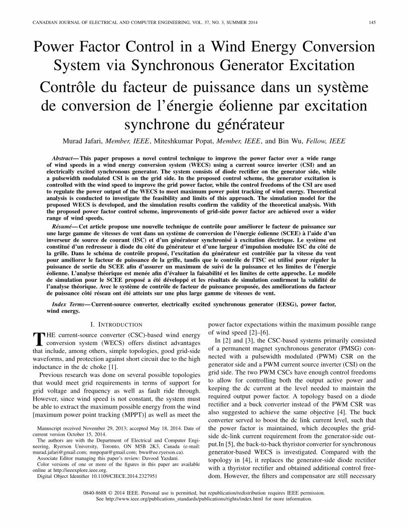
Fig. 4. Proposed system control scheme.
It is possible at each wind speed, depending on excitation,that a real solution for the dc-link current cannot be obtained.This largely depends on the value of the generator inductance.The implication from this is that higher values of the synchro-nous inductance could limit the range of wind speed withinwhich a real value of the dc-link current that achieves MPPT.
III. GRID-SIDE CONVERTER: PWM CSI
The main objective of the CSI is to supply available dc-linkpower to the grid and maintain the desired dc-link current inthe system. It is necessary for proper commutation of the CSIswitches that a filter capacitor be connected at its grid side. Thecapacitor also serves to smooth the output signal and reducethe total harmonic distortion [11].
Since the diode rectifier on the generator side does not offerany control to the output power, the control scheme of the CSIis designed in such a way that it tracks the dc-link currentbased on MPPT at any given wind speed using the generatorparameters. As stated above, there are combinations of windspeeds and excitation values, where a real reference dc-linkcurrent cannot be found. The control scheme has to accountfor that. Furthermore, when calculating the grid-side invertercurrent, we have to consider the capacitor current, which isadded to the grid current
Iw = Ic + Igr. (6)
At very low wind speeds, the generator hardly produces anyactive power. Consequently, the grid side current ( Igr) is verylow. However, even at high wind speeds, the voltage dropacross the line inductance is minimal, which means that atalmost all the wind speeds, the capacitor voltage is close tothe grid voltage, and therefore, the capacitor current ( Ic) is
almost speed independent. At very low wind speeds, the grid-side inverter current ( Iw) is equal to the capacitor current andthe minimal dc-link current required by grid-side converter.For each desired grid-side power factor (leading or lagging),it is possible to calculate the minimum dc current required bythe converter at each wind speed.
Fig. 3 shows grid-side requirements for the dc-link currentfor different values of power factor (dotted lines) as well asthe generator-side required dc-link current for MPPT controlat different levels of excitation. To obtain the required powerfactor at the grid side, the generator must produce a dc-linkcurrent at least equal to or higher than the grid-side converterrequirement. However, to minimize losses, the dc-link currentis usually kept as close to the grid-side converter requirementas possible.
We can also see from Fig. 3 that the lower the generatorexcitation current, the higher the dc-link current at each windspeed with MPPT control. The proposed control strategy isdeveloped based on this idea.
IV. PROPOSED SYSTEM CONTROL
In the proposed control scheme, the CSI is used to controlthe active power output of the generator to meet MPPT. Thediode rectifier does not offer any control freedoms. Therefore,in the proposed system control, the generator excitation iscontrolled for the dc-link current regulation such that thedesired grid-side power factor can be achieved over a widerange of wind speeds.
To calculate the reference active power at each windspeed, the wind speed in pu is cubed and multiplied by therated power, based on MPPT. The desired power factor isused to calculate the reference reactive power. The reference
148 CANADIAN JOURNAL OF ELECTRICAL AND COMPUTER ENGINEERING, VOL. 37, NO. 3, SUMMER 2014
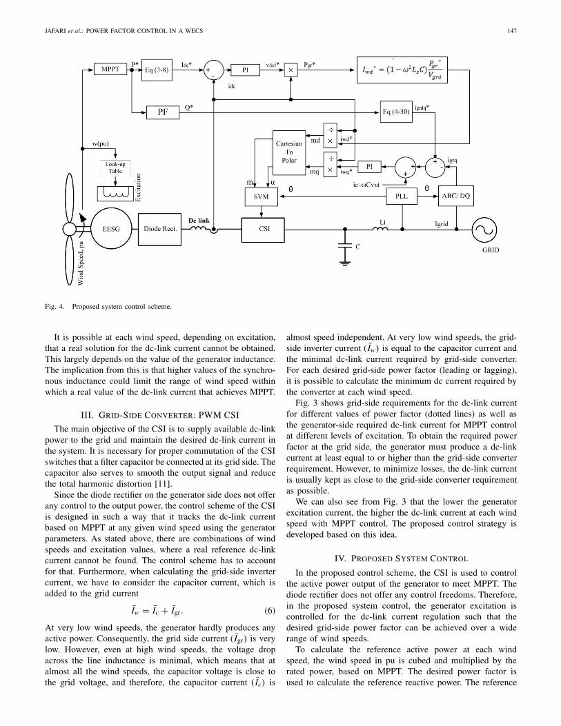
Fig. 5. Excitation control strategy.
dc-link current is calculated using (4), and is comparedwith the measured value of the dc-link current to providereference for the dc voltage, which is then multiplied by thedc-link current to provide the reference for the grid-side activepower (Pgr−ref). Knowing Pgr−ref , the reference for the grid-side inverter d-axis current is calculated accounting for thecapacitor d-axis current as follows:
Iwd−ref = (1 − ω2 LlC)Pgr−ref
Vgr−d(7)
where Ll is the line inductance and C is the grid-side capacitor.The reference for the grid-side converter q-axis current can becalculated from the reference reactive power as follows:
Igrq= − Qref
1.5V. (8)
Fig. 4 shows the block diagram of the proposed controlscheme. There are several ways to control excitation. One ofthem is to analytically calculate the value of the excitationcurrent needed to produce the dc-link current, which wouldbe just slightly above the grid-side converter requirement.
Another method is to create a lookup table that definesexcitation versus wind speed, such that the dc-link currentstays just above the grid-side converter dc-link current require-ment at that same wind speed, as shown in Fig. 5. Thedark line represents the value of the dc-link current producedby switching excitation to stay above the dotted line, whichrepresents the grid-side dc-link current requirement for unitypower factor.
For each value of the power factor, the grid-side converterdc-link requirement changes, and therefore, a different lookuptable is needed. In the lookup table for the unity power factor,the per unit excitation voltage had approximately the samevalue as the wind speed, so the value of the wind speed perunit was used also for the excitation voltage.
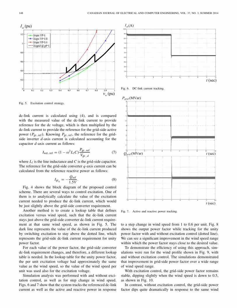
Simulation analysis was performed with and without exci-tation control, as well as for step change in wind speed.Figs. 6 and 7 show that the system tracks the referenced dc-linkcurrent as well as the active and reactive power in response
Fig. 6. DC-link current tracking.
Fig. 7. Active and reactive power tracking.
to a step change in wind speed from 1 to 0.6 per unit. Fig. 8shows the output power factor while tracking for the unitypower factor with and without excitation control (dotted line).We can see a significant improvement in the wind speed rangewithin which the power factor stays close to the desired value.
To demonstrate the efficiency of using this approach, sim-ulations were run for the wind profile shown in Fig. 9, withand without excitation control. The simulations demonstratedthat improvement in grid-side power factor over a wide rangeof wind speed range.
With excitation control, the grid-side power factor remainsstable, dipping slightly when the wind speed is down to 0.5,as shown in Fig. 10.
In contrast, without excitation control, the grid-side powerfactor dips quite dramatically in response to the same wind

JAFARI et al.: POWER FACTOR CONTROL IN A WECS 149
Fig. 8. Power factor with and without excitation control.
Fig. 9. Wind speed profile.
Fig. 10. Grid-side power factor with excitation control.
speed profile. Fig. 11 shows the variation in grid-side powerfactor with wind speed variation.
Figs. 12 and 13 show the dc-link current with and withoutexcitation control. As shown in Fig. 12, it is clear that at lowerwind speeds, the dc current stays higher with excitation control
Fig. 11. Grid-side power factor without excitation control.
Fig. 12. DC-link current with excitation control.
Fig. 13. DC-link current without excitation control.
in comparison with that without excitation control. Therefore,the required grid-side converter, dc-link current for the unitypower factor can be maintained.
150 CANADIAN JOURNAL OF ELECTRICAL AND COMPUTER ENGINEERING, VOL. 37, NO. 3, SUMMER 2014
V. CONCLUSION
A diode rectifier and PWM CSI-based topology is pro-posed for an EESG-based WECS. The proposed configurationprovides simple topology and a low-cost solution, but thegrid-side power factor of the system may be reduced at thelow wind speeds due to the lack of control freedoms ofthe generator-side diode rectifier as well as the impact ofcommutation in the diode rectifier on the dc link current.
Having investigated the impact of generator parameters oncommutation in the diode rectifier and excitation adjustmenton the dc current, a novel control scheme is developed, whichuses generator excitation to improve the power factor over awide range of wind speed. The unity power factor is achievedfor the wind speed range from 1 to 0.6 pu. In contrast, the grid-side power factors dip once wind speed falls below 0.8 pu. Thefeasibility of the proposed control scheme is verified throughdetailed simulation.
REFERENCES
[1] B. Wu, High Power Converters and AC Drives. Hoboken, NJ, USA:Wiley, 2006.
[2] J. Dai, J. Wang, B. Wu, D. Xu, and N. R. Zargari, “Low cost currentsource converter solutions for variable speed wind energy conversionsystems,” in Proc. IEEE Int. Electr. Mach. Drives Conf., May 2011,pp. 825–830.
[3] J. Dai, D. Xu, and B. Wu, “A novel control scheme for current-source-converter-based PMSG wind energy conversion systems,” IEEE Trans.Power Electron., vol. 24, no. 4, pp. 963–972, Apr. 2009.
[4] X. Tan, J. Dai, and B. Wu, “A novel converter configuration for windapplications using PWM CSI with diode rectifier and buck converter,”in Proc. IEEE Int. Electr. Mach. Drives Conf., May 2011, pp. 359–364.
[5] Y. Fujii, C. Hasegawa, F. Tatsuta, and S. Nishikata, “Dynamicperformance analysis of a hybrid wind turbine generator system,” inProc. IEEE ICEMS, Oct. 2008, pp. 2271–2276.
[6] J. Wang, J. Dai, B. Wu, and N.R. Zaragari, “Megawatt wind energyconversion system with diode rectifier and multilevel current sourceinverter,” in Proc. IEEE Energy Conver. Congr. Exposit. (ECCE),Sep. 2011, pp. 871–876.
[7] B. Wu, Y. Lang, N. Zargari, and S. Kouro, Power Conversion andControl of Wind Energy Systems. Hoboken, NJ, USA: Wiley, 2011.
[8] M. Popat, B. Wu, and N. R. Zargari, “A novel decoupled interconnectingmethod for current-source converter-based offshore wind farms,” IEEETrans. Power Electron., vol. 27, no. 10, pp. 4224–4233, Oct. 2012.
[9] N. Mohan, T. M. Undeland, and W. P. Robbins, Power Electronics:Converters, Applications, and Design. Hoboken, NJ, USA: Wiley, 2002.
[10] W. Quincy and C. Liuchen, “An intelligent maximum power extractionalgorithm for inverter-based variable speed wind turbine systems,” IEEETrans. Power Electron., vol. 19, no. 5, pp. 1242–1249, Sep. 2004.
[11] F. Blaabjerg and Z. Chen, Power Electronics for Modern Wind Turbines.San Rafael, CA, USA: Morgan & Claypool Publishers, 2006.
Murad Jafari (S’12–M’13) received the M.Sc.degree in electromechanical engineering fromOdessa National Polytechnic University, Ukraine, in1993, and the M.Eng. degree in electrical and com-puter engineering from Ryerson University, Canada,in 2014.
He currently works as a technical services managerat Bombardier Transportation in Thunder Bay.
Miteshkumar Popat (S’10–M’12) received theM.Tech. degree in electrical engineering from IndianInstitute of Technology (IIT), Roorkee, India, in2006, and the Ph.D. degree in electrical engineeringfrom Ryerson University, Toronto, ON, Canada, in2013.
Currently, he is working with DRS Technolo-gies, Canada. His current research interests includerenewable energy systems, advanced digital controlfor power electronics, and electric motor drives.
Bin Wu (S’89–M’92–SM’99–F’08) received thePh.D. degree in electrical and computer engineeringfrom the University of Toronto, Canada, in 1993.
After being with Rockwell Automation Canada, hejoined Ryerson University, Toronto, Canada, wherehe is currently a Professor and NSERC/RockwellIndustrial Research Chair in Power Electronics andElectric Drives. He has published more than 300technical papers, authored/coauthored two Wiley-IEEE Press books, and holds more than 20issued/pending patents in the areas of power elec-
tronics, electric drives, and renewable energy systems.Dr. Wu received the Gold Medal of the Governor General of Canada,
the Premier’s Research Excellence Award, Ryerson Distinguished ScholarAward, and the NSERC Synergy Award for Innovation. He is a fellow of theEngineering Institute of Canada (EIC) and Canadian Academy of Engineering(CAE).