Part 2: Tension creep testing machines — Verification of the...
22
Reference number ISO 7500-2:2006(E) INTERNATIONAL STANDARD ISO 7500-2 Second edition 2006-12-15 Metallic materials — Verification of static uniaxial testing machines — Part 2: Tension creep testing machines — Verification of the applied force Matériaux métalliques — Vérification des machines pour essais statiques uniaxiaux — Partie 2: Machines d'essai de fluage en traction — Vérification de la force appliquée No reproduction or networking permitted without license from IHS --`,,```,,,,````-`-`,,`,,`,`,,`---
Transcript of Part 2: Tension creep testing machines — Verification of the...
Reference numberISO 7500-2:2006(E)
© ISO 2006
INTERNATIONAL STANDARD
ISO7500-2
Second edition2006-12-15
Metallic materials — Verification of static uniaxial testing machines — Part 2: Tension creep testing machines — Verification of the applied force
Matériaux métalliques — Vérification des machines pour essais statiques uniaxiaux —
Partie 2: Machines d'essai de fluage en traction — Vérification de la force appliquée
Copyright International Organization for Standardization Provided by IHS under license with ISO
Not for ResaleNo reproduction or networking permitted without license from IHS
--`,,```,,,,````-`-`,,`,,`,`,,`---
ISO 7500-2:2006(E)
PDF disclaimer This PDF file may contain embedded typefaces. In accordance with Adobe's licensing policy, this file may be printed or viewed but shall not be edited unless the typefaces which are embedded are licensed to and installed on the computer performing the editing. In downloading this file, parties accept therein the responsibility of not infringing Adobe's licensing policy. The ISO Central Secretariat accepts no liability in this area.
Adobe is a trademark of Adobe Systems Incorporated.
Details of the software products used to create this PDF file can be found in the General Info relative to the file; the PDF-creation parameters were optimized for printing. Every care has been taken to ensure that the file is suitable for use by ISO member bodies. In the unlikely event that a problem relating to it is found, please inform the Central Secretariat at the address given below.
© ISO 2006 All rights reserved. Unless otherwise specified, no part of this publication may be reproduced or utilized in any form or by any means, electronic or mechanical, including photocopying and microfilm, without permission in writing from either ISO at the address below or ISO's member body in the country of the requester.
ISO copyright office Case postale 56 • CH-1211 Geneva 20 Tel. + 41 22 749 01 11 Fax + 41 22 749 09 47 E-mail [email protected] Web www.iso.org
Published in Switzerland
ii © ISO 2006 – All rights reserved
Copyright International Organization for Standardization Provided by IHS under license with ISO
Not for ResaleNo reproduction or networking permitted without license from IHS
--`,,```,,,,````-`-`,,`,,`,`,,`---
ISO 7500-2:2006(E)
© ISO 2006 – All rights reserved iii
Contents Page
Foreword............................................................................................................................................................ iv 1 Scope ..................................................................................................................................................... 1 2 Normative references ........................................................................................................................... 1 3 Symbols and their meanings............................................................................................................... 2 4 General inspection of the testing machine ........................................................................................ 2 5 Verification of the force applied by the testing machine.................................................................. 3 5.1 General................................................................................................................................................... 3 5.2 Masses ................................................................................................................................................... 3 5.3 Determination of the discrimination threshold.................................................................................. 3 5.4 Determination of the lower limit of verification ................................................................................. 4 5.5 Test procedure ...................................................................................................................................... 4 5.6 Assessment of the force applied by the machine ............................................................................. 6 6 Class of the testing machine ............................................................................................................... 6 6.1 General................................................................................................................................................... 6 6.2 Lever-type creep testing machines..................................................................................................... 6 6.3 Creep testing machines with the force applied by direct acting masses ....................................... 7 6.4 Creep testing machines with the force applied directly by a spring............................................... 7 7 Verification report ................................................................................................................................. 8 8 Intervals between verifications ........................................................................................................... 8 Annex A (normative) General inspection of the testing machine ................................................................. 9
Copyright International Organization for Standardization Provided by IHS under license with ISO
Not for ResaleNo reproduction or networking permitted without license from IHS
--`,,```,,,,````-`-`,,`,,`,`,,`---

ISO 7500-2:2006(E)
iv © ISO 2006 – All rights reserved
Foreword
ISO (the International Organization for Standardization) is a worldwide federation of national standards bodies (ISO member bodies). The work of preparing International Standards is normally carried out through ISO technical committees. Each member body interested in a subject for which a technical committee has been established has the right to be represented on that committee. International organizations, governmental and non-governmental, in liaison with ISO, also take part in the work. ISO collaborates closely with the International Electrotechnical Commission (IEC) on all matters of electrotechnical standardization.
International Standards are drafted in accordance with the rules given in the ISO/IEC Directives, Part 2.
The main task of technical committees is to prepare International Standards. Draft International Standards adopted by the technical committees are circulated to the member bodies for voting. Publication as an International Standard requires approval by at least 75 % of the member bodies casting a vote.
Attention is drawn to the possibility that some of the elements of this document may be the subject of patent rights. ISO shall not be held responsible for identifying any or all such patent rights.
ISO 7500-2 was prepared by Technical Committee ISO/TC 164, Mechanical testing of metals, Subcommittee SC 1, Uniaxial testing.
This second edition cancels and replaces the first edition (ISO 7500-2:1996), which has been technically revised.
ISO 7500 consists of the following parts, under the general title Metallic materials — Verification of static uniaxial testing machines:
⎯ Part 1: Tension/compression testing machines — Verification and calibration of the force-measuring system
⎯ Part 2: Tension creep testing machines — Verification of the applied force
Copyright International Organization for Standardization Provided by IHS under license with ISO
Not for ResaleNo reproduction or networking permitted without license from IHS
--`,,```,,,,````-`-`,,`,,`,`,,`---
INTERNATIONAL STANDARD ISO 7500-2:2006(E)
© ISO 2006 – All rights reserved 1
Metallic materials — Verification of static uniaxial testing machines —
Part 2: Tension creep testing machines — Verification of the applied force
1 Scope
This part of ISO 7500 specifies the verification of testing machines used for uniaxial creep testing in tension in accordance with ISO 204.
The verification consists of
⎯ a general inspection of the testing machine, and
⎯ a verification of the force applied by the testing machine.
This part of ISO 7500 applies to dead-weight machines, lever-type creep testing machines and direct-spring-loading machines.
Machines with a force-measuring system 1 ) should be verified in accordance with ISO 7500-1, Metallic materials — Verification of static uniaxial testing machines — Part 1: Tension/compression testing machines — Verification and calibration of the force-measuring system.
2 Normative references
The following referenced documents are indispensable for the application of this document. For dated references, only the edition cited applies. For undated references, the latest edition of the referenced document (including any amendments) applies.
ISO 204, Metallic materials — Uniaxial creep testing in tension — Method of test
ISO 376, Metallic materials — Calibration of force-proving instruments used for the verification of uniaxial testing machines
1) For the purposes of this part of ISO 7500, a force-measuring system comprises the load cell plus conditioning plus indicator.
Copyright International Organization for Standardization Provided by IHS under license with ISO
Not for ResaleNo reproduction or networking permitted without license from IHS
--`,,```,,,,````-`-`,,`,,`,`,,`---
ISO 7500-2:2006(E)
2 © ISO 2006 – All rights reserved
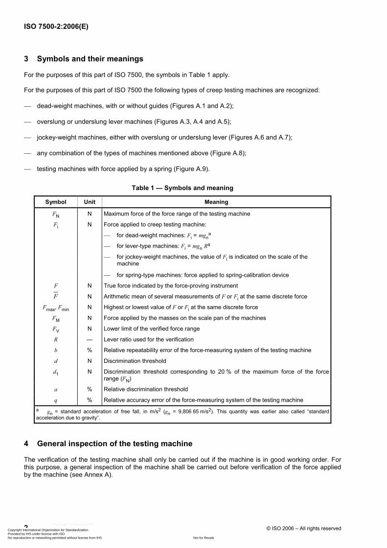
3 Symbols and their meanings
For the purposes of this part of ISO 7500, the symbols in Table 1 apply.
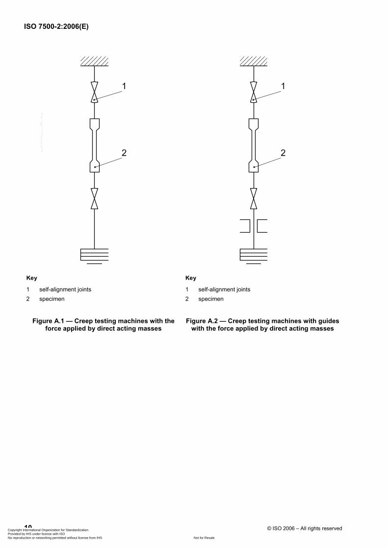
For the purposes of this part of ISO 7500 the following types of creep testing machines are recognized:
⎯ dead-weight machines, with or without guides (Figures A.1 and A.2);
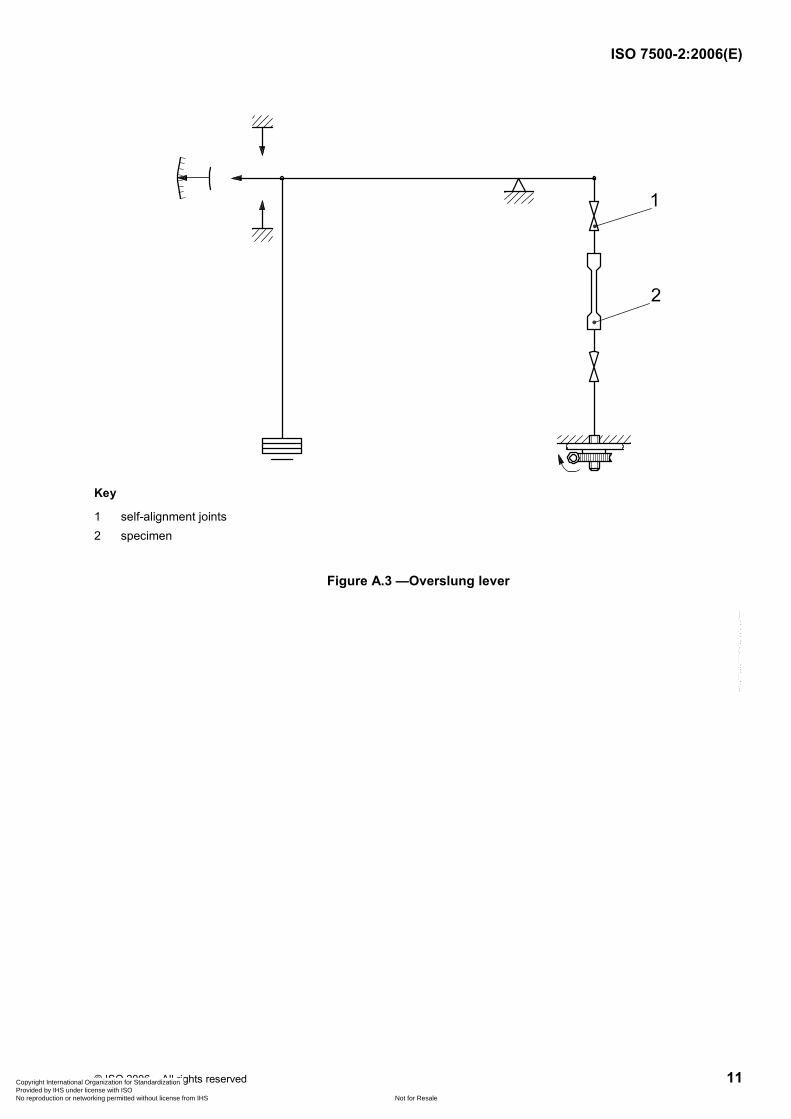
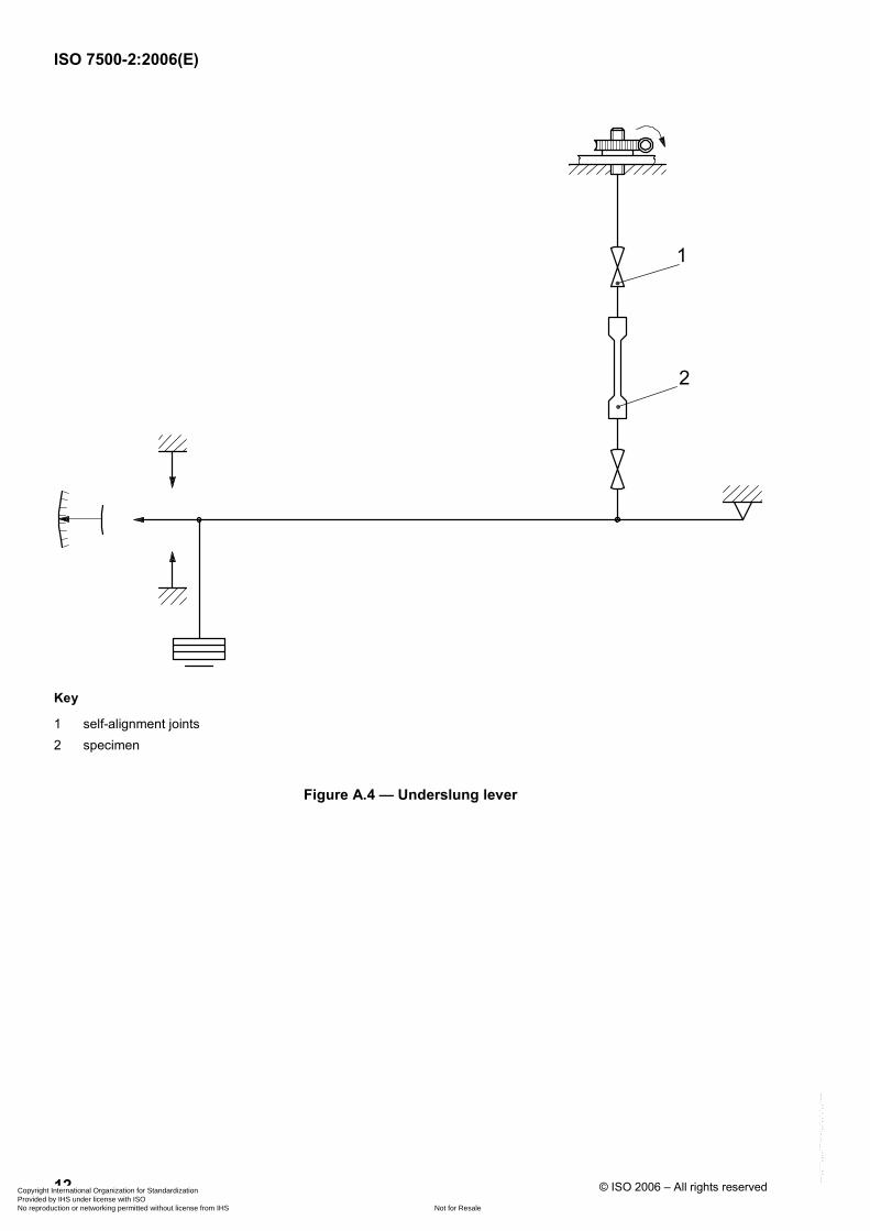
⎯ overslung or underslung lever machines (Figures A.3, A.4 and A.5);
⎯ jockey-weight machines, either with overslung or underslung lever (Figures A.6 and A.7);
⎯ any combination of the types of machines mentioned above (Figure A.8);
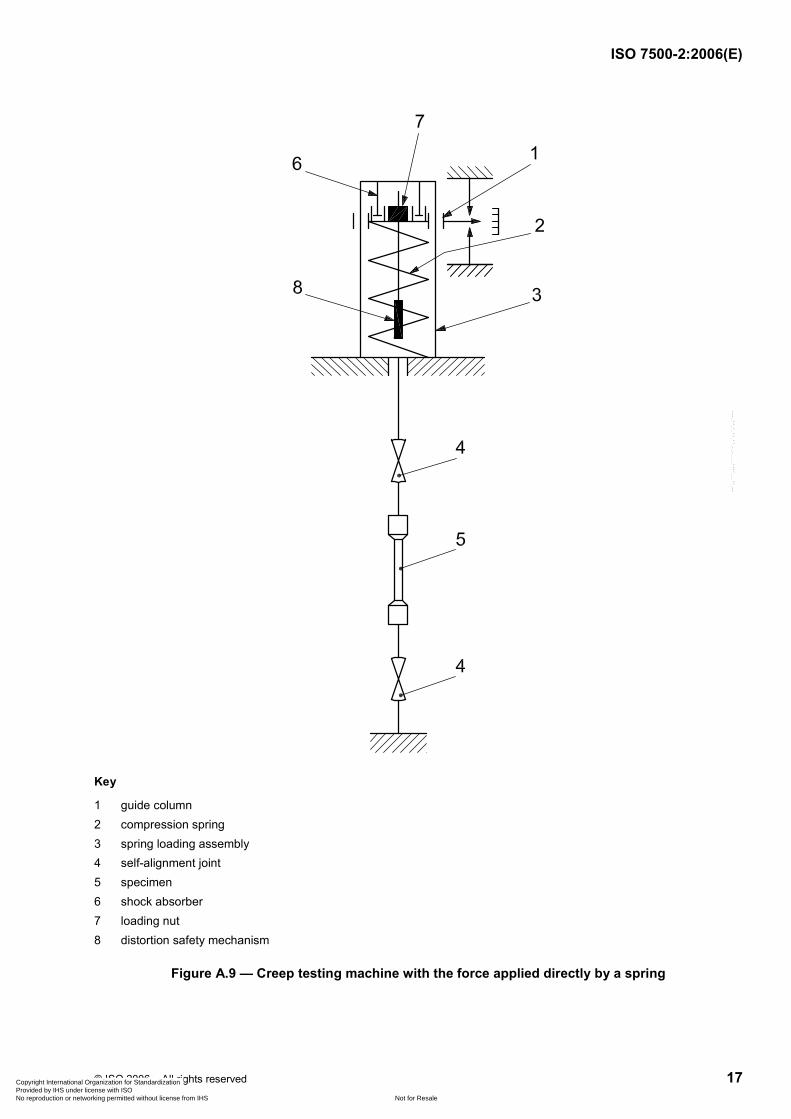
⎯ testing machines with force applied by a spring (Figure A.9).
Table 1 — Symbols and meaning
Symbol Unit Meaning
FN N Maximum force of the force range of the testing machine
Fi N Force applied to creep testing machine:
⎯ for dead-weight machines: Fi = mgna
⎯ for lever-type machines: Fi = mgn Ra
⎯ for jockey-weight machines, the value of Fi is indicated on the scale of the machine
⎯ for spring-type machines: force applied to spring-calibration device
F N True force indicated by the force-proving instrument
F N Arithmetic mean of several measurements of F or Fi at the same discrete force
Fmax, Fmin N Highest or lowest value of F or Fi at the same discrete force
FM N Force applied by the masses on the scale pan of the machines
FV N Lower limit of the verified force range
R — Lever ratio used for the verification
b % Relative repeatability error of the force-measuring system of the testing machine
d N Discrimination threshold
d1 N Discrimination threshold corresponding to 20 % of the maximum force of the force range (FN)
a % Relative discrimination threshold
q % Relative accuracy error of the force-measuring system of the testing machine a gn = standard acceleration of free fall, in m/s2 (gn = 9,806 65 m/s2). This quantity was earlier also called “standard acceleration due to gravity”.
4 General inspection of the testing machine
The verification of the testing machine shall only be carried out if the machine is in good working order. For this purpose, a general inspection of the machine shall be carried out before verification of the force applied by the machine (see Annex A).
Copyright International Organization for Standardization Provided by IHS under license with ISO
Not for ResaleNo reproduction or networking permitted without license from IHS
--`,,```,,,,````-`-`,,`,,`,`,,`---
ISO 7500-2:2006(E)
© ISO 2006 – All rights reserved 3
5 Verification of the force applied by the testing machine
5.1 General
This verification shall be carried out for each of the force ranges used. If the testing machine has several force ranges, each force range2) shall be regarded as a separate testing machine.
This verification shall be carried out using tension-force-proving instruments. These instruments shall be in accordance with ISO 376. The class of the force-proving instrument shall be equal or superior to the class determined for the creep testing machine.
5.2 Masses
The masses used to apply the forces during the verification can be either
a) known masses with an accuracy equal to or better than ± 0,1 %, verified at least every five years, or
b) masses dedicated for use with a given creep testing machine, applied in the same sequence as during the test.
5.3 Determination of the discrimination threshold
The discrimination threshold (d) of the machine is defined as the smallest increment of force that can be applied and detected during the verification procedure.
The discrimination threshold (d) shall be determined at 20 %, 60 % and 100 % of the maximum force FN of the force range. If forces of a magnitude less than 0,2 FN are to be tested (see 5.2), the discrimination threshold shall additionally be determined at the lower limit of the provided testing range.
The discrimination threshold (d) is measured at the magnitude of the force resulting from the smallest mass added to, or removed from, the scale pan of the machine, or the force which corresponds to the smallest recordable movement of the jockey weight which causes a detectable change at the indicator of the force-proving instrument.
The relative discrimination threshold (a) is calculated for each level of force specified according to the following formula :
100daF
= × (1)
and shall remain within the limits given in Table 3 for the class of machine considered.
The discrimination threshold (d) shall be expressed in newtons.
2) Force range means, in the case of a deadweight machine, the range over which the machine is to be used; in the case of a lever-type machine it is the force range for each separate lever ratio.
Copyright International Organization for Standardization Provided by IHS under license with ISO
Not for ResaleNo reproduction or networking permitted without license from IHS
--`,,```,,,,````-`-`,,`,,`,`,,`---
ISO 7500-2:2006(E)
4 © ISO 2006 – All rights reserved
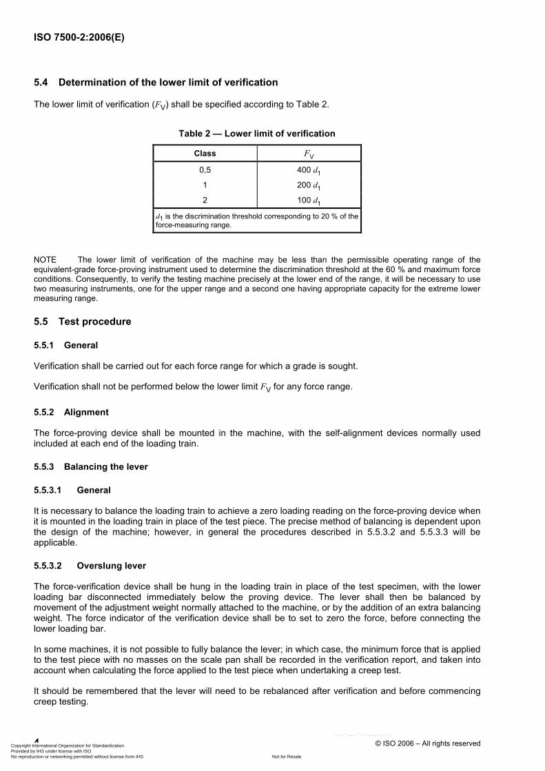
5.4 Determination of the lower limit of verification
The lower limit of verification (FV) shall be specified according to Table 2.
Table 2 — Lower limit of verification
Class FV
0,5 400 d1
1 200 d1
2 100 d1
d1 is the discrimination threshold corresponding to 20 % of the force-measuring range.
NOTE The lower limit of verification of the machine may be less than the permissible operating range of the equivalent-grade force-proving instrument used to determine the discrimination threshold at the 60 % and maximum force conditions. Consequently, to verify the testing machine precisely at the lower end of the range, it will be necessary to use two measuring instruments, one for the upper range and a second one having appropriate capacity for the extreme lower measuring range.
5.5 Test procedure
5.5.1 General
Verification shall be carried out for each force range for which a grade is sought.
Verification shall not be performed below the lower limit FV for any force range.
5.5.2 Alignment
The force-proving device shall be mounted in the machine, with the self-alignment devices normally used included at each end of the loading train.
5.5.3 Balancing the lever
5.5.3.1 General
It is necessary to balance the loading train to achieve a zero loading reading on the force-proving device when it is mounted in the loading train in place of the test piece. The precise method of balancing is dependent upon the design of the machine; however, in general the procedures described in 5.5.3.2 and 5.5.3.3 will be applicable.
5.5.3.2 Overslung lever
The force-verification device shall be hung in the loading train in place of the test specimen, with the lower loading bar disconnected immediately below the proving device. The lever shall then be balanced by movement of the adjustment weight normally attached to the machine, or by the addition of an extra balancing weight. The force indicator of the verification device shall be to set to zero the force, before connecting the lower loading bar.
In some machines, it is not possible to fully balance the lever; in which case, the minimum force that is applied to the test piece with no masses on the scale pan shall be recorded in the verification report, and taken into account when calculating the force applied to the test piece when undertaking a creep test.
It should be remembered that the lever will need to be rebalanced after verification and before commencing creep testing.
Copyright International Organization for Standardization Provided by IHS under license with ISO
Not for ResaleNo reproduction or networking permitted without license from IHS
--`,,```,,,,````-`-`,,`,,`,`,,`---
ISO 7500-2:2006(E)
© ISO 2006 – All rights reserved 5
5.5.3.3 Underslung levers
Because of the geometrical design of underslung lever machines, it is seldom possible to balance on the mass of the lower loading bars, lever and scale pan. It is therefore necessary to zero the force-proving device with the lower loading bar disconnected, and then merely to note the force applied when the loading train is reconnected and the system adjusted to bring the lever to the normal operating position with no masses placed on the scale pan. If this force is greater than that specified in 5.4. then it shall become the lower limit of verification.
5.5.4 Temperature compensation
Allow sufficient time for the verification equipment to attain a stable temperature. Record the temperature at the beginning and end of the application of each series of forces. Where necessary, apply temperature corrections to the deflections of proving devices using the equations given in ISO 376.
5.5.5 Conditioning
In order to condition the system, it is necessary to exercise the creep testing machine and force-proving device three times between zero force and the maximum force to be measured. Then, reset the force-proving device to the zero force position.
5.5.6 Selection of test forces
Apply a series of at least five approximately equispaced forces upwards from 20 % of the force range or the lower limit of verification, whichever is greater.
When required, apply additional forces below 20 % of the force range down to the lower limit of verification (see 5.4). Apply one force for each increment of 5 %, or portion thereof, of the scale to be verified below 20 % of the force range.
5.5.7 Application of test forces
For each range, apply the series of forces in ascending order and repeat each series to give three series of such forces. Completely remove the force after each series of applications.
All three series of forces shall be applied with the loading system at the mid-point of the normal operating range (zero position). The measurements shall be conducted after the system has been stabilized, especially for machines with a damping device.
NOTE On a creep testing machine with an overslung lever or a single underslung lever, this requirement implies that the three series of forces are applied with the lever in the horizontal position.
The force-proving device should be rotated ~ 120° between the load series. After each rotation, the system should be preloaded.
Ensure that the application of each test force is free of shock and vibration, so that the force does not exceed its nominal value by more than the maximum permissible error for the machine class in question.
In the case of lever-type machines, ensure that the permissible deviation of the lever from its horizontal position is exactly marked. In the range between these marked inclinations of the lever, verify that the force is within the permitted limits. Also verify the lowest and highest force of the range at the lower position of the lever. This procedure ensures that the deviation of the test force from its nominal value during the total duration of the creep test is within the limits of the maximum permissible error for the machine class in question.
The spring of testing machines with direct loading shall be calibrated in a spring-force calibration device. The spring loading assembly shall be removed from the creep testing machine and installed in the spring-force calibration device. The interface between the spring loading assembly and the spring-force calibration device shall be identical to the interface in the testing machine.
Copyright International Organization for Standardization Provided by IHS under license with ISO
Not for ResaleNo reproduction or networking permitted without license from IHS
--`,,```,,,,````-`-`,,`,,`,`,,`---
ISO 7500-2:2006(E)
6 © ISO 2006 – All rights reserved
The force-proving device shall be mounted in the spring-force calibration device with self-aligning devices included at each end of the loading train.
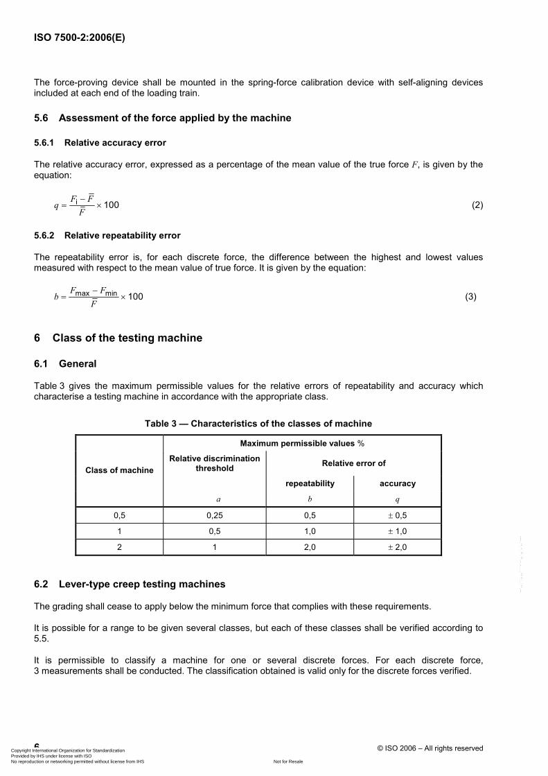
5.6 Assessment of the force applied by the machine
5.6.1 Relative accuracy error
The relative accuracy error, expressed as a percentage of the mean value of the true force F, is given by the equation:
i 100F F
qF−
= × (2)
5.6.2 Relative repeatability error
The repeatability error is, for each discrete force, the difference between the highest and lowest values measured with respect to the mean value of true force. It is given by the equation:
max min 100F F
bF−
= × (3)
6 Class of the testing machine
6.1 General
Table 3 gives the maximum permissible values for the relative errors of repeatability and accuracy which characterise a testing machine in accordance with the appropriate class.
Table 3 — Characteristics of the classes of machine
Maximum permissible values %
Relative discrimination threshold Relative error of
repeatability accuracy Class of machine
a b q
0,5 0,25 0,5 ± 0,5
1 0,5 1,0 ± 1,0
2 1 2,0 ± 2,0
6.2 Lever-type creep testing machines
The grading shall cease to apply below the minimum force that complies with these requirements.
It is possible for a range to be given several classes, but each of these classes shall be verified according to 5.5.
It is permissible to classify a machine for one or several discrete forces. For each discrete force, 3 measurements shall be conducted. The classification obtained is valid only for the discrete forces verified.
Copyright International Organization for Standardization Provided by IHS under license with ISO
Not for ResaleNo reproduction or networking permitted without license from IHS
--`,,```,,,,````-`-`,,`,,`,`,,`---
ISO 7500-2:2006(E)
© ISO 2006 – All rights reserved 7
6.3 Creep testing machines with the force applied by direct acting masses
Normally, the grading will be determined by the accuracies of the masses used to apply the verification forces and of the mass of the load suspension system below the test piece. However, for machines with guides below the test piece which could introduce friction effects, it is necessary to calibrate the machine using a proving device. The calibration authority shall be satisfied that the axis of loading passes through the longitudinal axis of the test piece.
6.4 Creep testing machines with the force applied directly by a spring
The grade of the test machine depends on the force accuracy of the calibrated spring.
It is permissible to classify a spring for one or several discrete forces. For each discrete force 3 measurements shall be conducted.
The classification obtained is valid only for the discrete forces verified.
If discrete forces are to be inspected during testing, specific guidelines need to be developed for the testing machine.
A schematic representation of a creep testing machine with the force applied directly by a spring is shown in Figure A.9.
The spring-force calibration device shall be verified at intervals not exceeding one year.
The spring loading assembly shall be recalibrated if it has been dismantled for repair or adjustment.
The verification in the creep testing machine shall be performed at intervals not exceeding five years (for example, see Table 4).
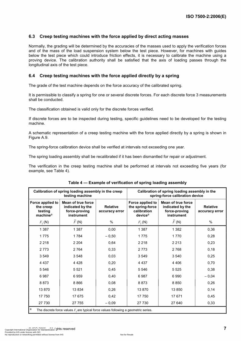
Table 4 — Example of verification of spring loading assembly
Calibration of spring loading assembly in the creep testing machine
Calibration of spring loading assembly in the spring-force calibration device
Force applied to the creep
testing machinea
Mean of true force indicated by the
force-proving instrument
Relative accuracy error
Force applied to the spring-force
calibration devicea
Mean of true force indicated by the
force-proving instrument
Relative accuracy error
Fi (N) (N)F % Fi (N) (N)F %
1 387 1 387 0,00 1 387 1 382 0,36
1 775 1 784 – 0,50 1 775 1 770 0,28
2 218 2 204 0,64 2 218 2 213 0,23
2 773 2 764 0,33 2 773 2 768 0,18
3 549 3 548 0,03 3 549 3 540 0,25
4 437 4 428 0,20 4 437 4 406 0,70
5 546 5 521 0,45 5 546 5 525 0,38
6 987 6 959 0,40 6 987 6 990 – 0,04
8 873 8 866 0,08 8 873 8 850 0,26
13 870 13 834 0,26 13 870 13 850 0,14
17 750 17 675 0,42 17 750 17 671 0,45
27 730 27 755 – 0,09 27 730 27 640 0,33 a The discrete force values Fi are typical force values following a geometric series.
Copyright International Organization for Standardization Provided by IHS under license with ISO
Not for ResaleNo reproduction or networking permitted without license from IHS
--`,,```,,,,````-`-`,,`,,`,`,,`---
ISO 7500-2:2006(E)
8 © ISO 2006 – All rights reserved
7 Verification report
The verification report shall contain at least the following information.
a) General information:
1) reference to this part of ISO 7500;
2) identification of the testing machine (type, make, serial number);
3) location of the machine;
4) the method of verification used (see 5.1) and the identity, class and date of the last calibration certificate of the verification equipment used;
5) the average temperature of the verification equipment at the time of verification;
6) date of verification;
7) name or mark of the verifying service which performed the verification.
b) Results of verification:
1) for each force-measuring system used, the class of each range verified and, if requested, the discrete values of relative errors of accuracy and repeatability;
2) the lever ratio (R) used for each force range, where applicable;
3) when discrete forces have been verified, the actual forces, the class(es) obtained and, if requested, the discrete values of relative error of repeatability;
4) any anomaly found during the general inspection.
8 Intervals between verifications
The machine shall be verified at intervals not exceeding five years. However, if the predicted test life exceeds the date of expiry of the verification certificate, then the machine shall be reverified prior to commencement of the creep test. Any machine shall also be reverified if it has been dismantled for moving, or subject to major repair or adjustment.
NOTE If the machine is used for short-term creep tests, it could be recommended to verify the machine at intervals not exceeding two years.
Copyright International Organization for Standardization Provided by IHS under license with ISO
Not for ResaleNo reproduction or networking permitted without license from IHS
--`,,```,,,,````-`-`,,`,,`,`,,`---
ISO 7500-2:2006(E)
© ISO 2006 – All rights reserved 9
Annex A (normative)
General inspection of the testing machine
The general inspection of the testing machine, which shall be carried out before the verification of the machine (see clause 5), shall comprise the following.
A.1 Visual examination
The visual examination shall verify:
a) that the machine is in good working order and not adversely affected by certain aspects of its general condition, such as:
1) significant wear of the knife edges, supporting points, bearings, grips or any defect in the guiding elements of the pull rods;
2) looseness in mounting of columns and fixed crossheads;
b) that the lever system is free to swing smoothly over its operating range;
c) that the machine is not affected by environmental conditions (vibration, effect of corrosion, local temperature variations, etc.);
d) to ensure that the line of action of force, as far as possible, runs through the centres of the knife edges or ball seatings of the loading train.
A.2 Inspection of the structure of the machine
A check shall be made to ensure that the structure and gripping systems will permit the force to be applied axially.
Figures A.1 to A.9 are the schematic representations of operating principles of tensile creep machines.
NOTE Figures A.1 to A.9 are given as examples.
Copyright International Organization for Standardization Provided by IHS under license with ISO
Not for ResaleNo reproduction or networking permitted without license from IHS
--`,,```,,,,````-`-`,,`,,`,`,,`---
ISO 7500-2:2006(E)
10 © ISO 2006 – All rights reserved
Key
1 self-alignment joints 2 specimen
Key
1 self-alignment joints 2 specimen
Figure A.1 — Creep testing machines with the force applied by direct acting masses
Figure A.2 — Creep testing machines with guides with the force applied by direct acting masses
Copyright International Organization for Standardization Provided by IHS under license with ISO
Not for ResaleNo reproduction or networking permitted without license from IHS
--`,,```,,,,````-`-`,,`,,`,`,,`---
ISO 7500-2:2006(E)
© ISO 2006 – All rights reserved 11
Key
1 self-alignment joints 2 specimen
Figure A.3 —Overslung lever
Copyright International Organization for Standardization Provided by IHS under license with ISO
Not for ResaleNo reproduction or networking permitted without license from IHS
--`,,```,,,,````-`-`,,`,,`,`,,`---
ISO 7500-2:2006(E)
12 © ISO 2006 – All rights reserved
Key
1 self-alignment joints 2 specimen
Figure A.4 — Underslung lever
Copyright International Organization for Standardization Provided by IHS under license with ISO
Not for ResaleNo reproduction or networking permitted without license from IHS
--`,,```,,,,````-`-`,,`,,`,`,,`---
ISO 7500-2:2006(E)
© ISO 2006 – All rights reserved 13
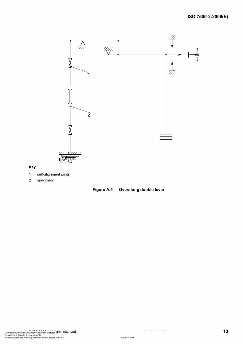
Key
1 self-alignment joints 2 specimen
Figure A.5 — Overslung double lever
Copyright International Organization for Standardization Provided by IHS under license with ISO
Not for ResaleNo reproduction or networking permitted without license from IHS
--`,,```,,,,````-`-`,,`,,`,`,,`---
ISO 7500-2:2006(E)
14 © ISO 2006 – All rights reserved
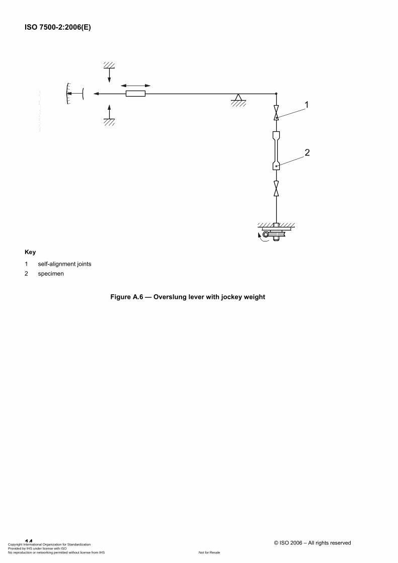
Key
1 self-alignment joints 2 specimen
Figure A.6 — Overslung lever with jockey weight
Copyright International Organization for Standardization Provided by IHS under license with ISO
Not for ResaleNo reproduction or networking permitted without license from IHS
--`,,```,,,,````-`-`,,`,,`,`,,`---
ISO 7500-2:2006(E)
© ISO 2006 – All rights reserved 15
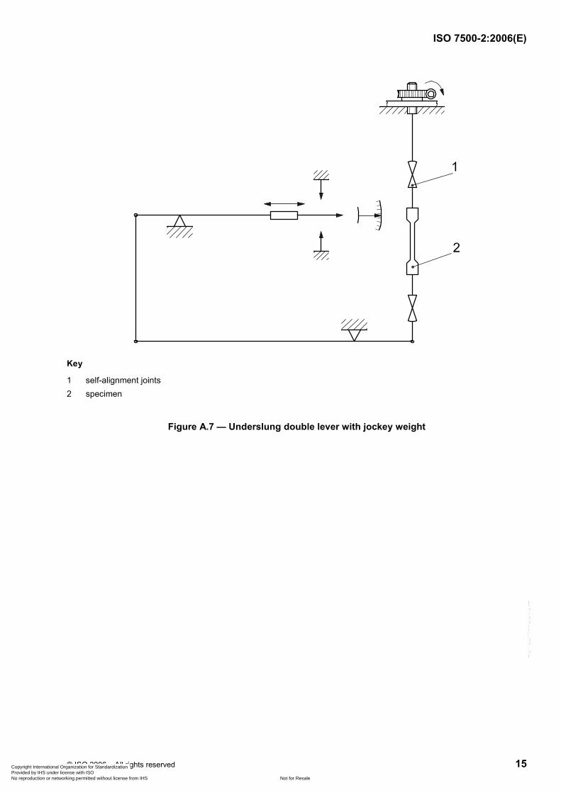
Key
1 self-alignment joints 2 specimen
Figure A.7 — Underslung double lever with jockey weight
Copyright International Organization for Standardization Provided by IHS under license with ISO
Not for ResaleNo reproduction or networking permitted without license from IHS
--`,,```,,,,````-`-`,,`,,`,`,,`---
ISO 7500-2:2006(E)
16 © ISO 2006 – All rights reserved
Key
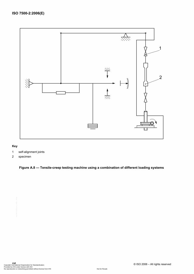
1 self-alignment joints 2 specimen
Figure A.8 — Tensile-creep testing machine using a combination of different loading systems
Copyright International Organization for Standardization Provided by IHS under license with ISO
Not for ResaleNo reproduction or networking permitted without license from IHS
--`,,```,,,,````-`-`,,`,,`,`,,`---
ISO 7500-2:2006(E)
© ISO 2006 – All rights reserved 17
Key
1 guide column 2 compression spring 3 spring loading assembly 4 self-alignment joint 5 specimen 6 shock absorber 7 loading nut 8 distortion safety mechanism
Figure A.9 — Creep testing machine with the force applied directly by a spring
Copyright International Organization for Standardization Provided by IHS under license with ISO
Not for ResaleNo reproduction or networking permitted without license from IHS
--`,,```,,,,````-`-`,,`,,`,`,,`---
ISO 7500-2:2006(E)
ICS 77.040.10 Price based on 17 pages
© ISO 2006 – All rights reserved
Copyright International Organization for Standardization Provided by IHS under license with ISO
Not for ResaleNo reproduction or networking permitted without license from IHS
--`,,```,,,,````-`-`,,`,,`,`,,`---