
Operation Manual SP 2012-09 (G19501383) IT-EN-DE-FR...
82
Cod. G19501383 2012-09 IT EN DE USO E MANUTENZIONE USE AND MAINTENANCE GEBRAUCH UND WARTUNG EMPLOI ET ENTRETIEN EMPLEO Y MANTENIMIENTO *) *) Valido per Paesi UE *) Valid for EU member countries *) Valable dans les Pays UE *) Gilt für EU-Mitgliedsländer *) Válido para Países UE MASCHIO GASPARDO S.p.A. SP SPRINT FR ES
Transcript of Operation Manual SP 2012-09 (G19501383) IT-EN-DE-FR...

Cod. G19501383 2012-09
ITENDE
USO E MANUTENZIONE
USE AND MAINTENANCE
GEBRAUCH UND WARTUNG
EMPLOI ET ENTRETIEN
EMPLEO Y MANTENIMIENTO*)
*) Valido per Paesi UE*) Valid for EU member countries*) Valable dans les Pays UE*) Gilt für EU-Mitgliedsländer*) Válido para Países UE
MASCHIO GASPARDO S.p.A.
SP SPRINTFRES
ITALIANO ENGLISH DEUTSCH
INDICE INDEX INHALT
2 cod. G19501383
1.0 Premessa ........................................... 51.1 Generalità ............................................. 51.2 Garanzia ............................................... 81.2.1 Scadenza garanzia............................... 81.3 Identifi cazione dell’attrezzatura ............ 8
2.0 Indicazioni generali di sicurezza ...... 92.1 Segnali di sicurezza e indicazione ....... 92.1.1 Segnali di avvertenza ........................... 92.1.2 Segnali di pericolo ................................ 92.1.3 Segnali di indicazione........................... 92.2 Norme di sicurezza e prevenzione infortuni............................................... 10
3.0 Descrizione della seminatrice ........ 133.1 Dati tecnici .......................................... 143.2 Disegno complessivo ......................... 153.3 Movimentazione ................................. 16
4.0 Norme d’uso ..................................... 174.1 Applicazione al trattore ...................... 174.1.1 Aggancio ............................................ 174.1.2 Sgancio della seminatrice dalla trattrice ....................................... 184.2 Adattamento albero cardanico ........... 184.3 Stabilita’ in trasporto seminatrice-trattore ............................ 184.4 Trasporto stradale .............................. 194.5 Selezione del seme ............................ 204.5.1 Distributore semi ................................ 204.5.2 Regolazione per la distribuzione ........ 224.6 Regolazioni......................................... 264.6.1 Regolazione profondità assolcatore ... 264.6.2 Regolazione pressione profondità assolcatore ......................................... 264.6.3 Esclusione del seminatore ................. 274.6.4 Scatola trasmissione seminatore ....... 274.7 Depressore ......................................... 274.8 Segnafi le ............................................ 284.8.1 Segnafi le a comando oleodinamico ... 284.8.2 Segnafi le a comando meccanico ....... 284.8.3 Regolazione dischi marcafi le.............. 294.9 Distribuzione dei prodotti chimici ........ 304.9.1 Regolazione interratori fertilizzante .... 304.9.2 Speedy set ......................................... 314.9.3 Spandiconcime -tabella distribuzione ... 314.9.4 Speedy set -tabella distribuzione ....... 324.9.5 Microgranulatore -tabella distribuzione .... 334.10 Allestimenti ......................................... 34
5.0 Operazioni per la messa in servizio della macchina.................................. 365.1 A macchina nuova .............................. 365.2 Verifi ca e manutenzione preventiva .... 365.3 Collegamento alla trattrice.................. 365.4 Preparativi per la semina.................... 365.5 Distribuzione di prodotti chimici .......... 365.6 Durante la semina .............................. 375.7 Fine lavoro.......................................... 375.8 Messa a riposo giornaliero ................. 37
6.0 Manutenzione ................................... 386.1 Piano di manutenzione ....................... 396.2 Inconvenienti, cause e rimedi ............. 40
7.0 Demolizione e smaltimento ............. 41
Dichiarazione di conformità .............194-195
1.0 Introduction ..................................... 431.1 General .............................................. 431.2 Guarantee ......................................... 461.2.1 Expiry of guarantee ........................... 461.3 Identifi cation ...................................... 46
2.0 General safety rules ........................ 472.1 Danger and indicator signals ............. 472.1.1 Warning signals ................................. 472.1.2 Warning signals ................................. 472.1.3 Indicator signals ................................ 472.2 Safety regulations and accident prevention .......................................... 48
3.0 Description of the seeder ............... 513.1 Technical data ................................... 523.2 Assembly drawing ............................. 533.3 Handling ............................................ 54
4.0 Norme d’uso ..................................... 554.1 Attachment to the tractor .................... 554.1.1 Hooking .............................................. 554.1.2 Unhooking the seed drill from the tractor ........................................... 564.2 Adapting the cardan shaft .................. 564.3 Stability of planting unit and tractor during transport ................................. 564.4 Transport on road ............................... 574.5 Seed selection .................................... 584.5.1 Seed distributor .................................. 584.5.2 Distribution adjustment ....................... 604.6 Adjustments........................................ 644.6.1 Furrow opener depth adjustment ....... 644.6.2 Furrow opener pressure adjustment .. 644.6.3 Seeder exclusion ................................ 654.6.4 Planting unittransmisssion.................. 654.7 Vacuum pump .................................... 654.8 Row marker ........................................ 664.8.1 Hydraulic row marker ......................... 664.8.2 Mechanical row marker automatic control ................................ 664.8.3 Row marker disk adjustment .............. 674.9 Distribution of chemical products ....... 684.9.1 Regulating the fertilizer interring hoe.. 684.9.2 Speedy set ......................................... 694.9.3 Fertilizer distributor -distribution table 694.9.4 Speedy set -distribution table ............. 704.9.5 Microgranulator -distribution table ...... 714.10 Preparation ......................................... 72
5.0 Operations for putting the machine into service ...................................... 745.1 When the machine is new .................. 745.2 Checks and preventative maintenance ....................................... 745.3 Attachment the tractor ........................ 745.4 Preparing for seeding ......................... 745.5 Distribution of chemical products ....... 745.6 During seeding ................................... 755.7 The end of operation .......................... 755.8 Daily rest period ................................. 75
6.0 Maintenance...................................... 766.1 Maintenance plan - summary table .... 776.2 Inconveniences, causes and remedies . 78
7.0 Demolition and disposal .................. 79
Conformity declaration .....................194-195
1.0 Vorwort ............................................. 811.1 Allgemeines ....................................... 811.2 Garantie ............................................. 841.2.1 Verfall des Garantieanspruchs .......... 841.3 Identifi zierung .................................... 84
2.0 Allgemeine Sicherheitsanweisungen . 852.1 Warnsignale undAnzeigesignale ....... 852.1.1 Warnsignale ...................................... 852.1.2 Gefahrsignale .................................... 852.1.3 Anzeigesignale .................................. 852.2 Sicherheits- und Unfallverhütungs-
Bestimmungen .................................. 86
3.0 Beschreibung der Sämaschine ...... 893.1 Technische Daten .............................. 903.2 Zusammenfassend ............................ 913.3 Fortbewegung ................................... 92
4.0 Betriebs-anleitungen........................ 934.1 Einbau am schlepper ......................... 934.1.1 Ankuppeln .......................................... 924.1.2 Abkuppeln der Säemaschine vom Schlepper ........................................... 944.2 Anpassung der gelenkwelle ............... 944.3 Stabilität von Sämaschine-Schlepper beim Transport .................................. 944.4 Teilnahme am Straßenverkehr ........... 954.5 Saatzucht ........................................... 964.5.1 Säapparat ........................................... 964.5.2 Einstellung des Aussaat ..................... 984.6 Regelungen ...................................... 1024.6.1 Einstellung der Sascharen-Reissertiefe .................... 1024.6.2 Einstellung des Schubdrucks des Säscharen-Reissers ......................... 1024.6.3 Ausschluss des Saelements ............ 1034.6.4 Getriebekasten Sämaschine ............ 1034.7 Vakuumpumpe ................................. 1034.8 Spurreisser ....................................... 1044.8.1 Hydraulischer spurreisser................. 1044.8.2 Automatiksteuerung des mechanischen spurreissers.............. 1044.8.3 Einstellung der spurmarkiererscheiben . 1054.9 Verteilung der chemischen produkte 1064.9.1 Einstellung der düngereingrabvorrichtungen ............ 1064.9.2 Speedy set ....................................... 1074.9.3 Düngerstreuer -Düngermengetabelle 1074.9.4 Speedy set - Düngermengetabelle ... 1084.9.5 Mikrogranulatstreuer - Düngermengetabelle ........................ 1094.10 Ausführungen ................................... 110
5.0 Inbetriebsetzung der Maschine..... 1125.1 A neue Maschine .............................. 1125.2 Vorbeugende Kontrollen und Wartung ..................................... 1125.3 Einbau am Schlepper ....................... 1125.4 Vorbereitungen Für die Aussaat ....... 1125.5 Verteilung der Chemischen Produkte 1125.6 Während der Aussaat ....................... 1135.7 Am ende der Aussaat ....................... 1135.8 Parken des Geräts bei Arbeitsende.. 113
6.0 Wartung ........................................... 1146.1 Wartungsplan - Übersichtstabelle .... 1156.2 Störungen, deren ursachen und behe-
bung ................................................. 116
7.0 Zerlegen und Entsorgen der Maschine . 117
Konformitätsenklärung .....................194-195
FRANÇAIS ESPAÑOL
TABLES DE MATIERES INDICE
3cod. G19501383
1.0 Introduction ................................... 1191.1 Généralités ...................................... 1191.2 Garantie ........................................... 1221.2.1 Expiration de la garantie .................. 1221.3 Identifi cation .................................... 122
2.0 Indications générales de sécurité 1232.1 Signaux de securite d’indication ...... 1232.1.1 Signaux de recommandation ........... 1232.1.2 Signaux de danger .......................... 1232.1.3 Signaux de indication ...................... 1232.2 Normes de securite et de prevention des accidents .................................. 124
3.0 Description de la machine ............ 1273.1 Donnees techniques ........................ 1283.2 Dessin global ................................... 1293.3 Movimentation ................................. 130
4.0 Normes d’emploi ............................ 1314.1 Attelage au tracteur ......................... 1314.1.1 Accrochage ...................................... 1314.1.2 Decrochage de element semeur du tracteur ........................................ 1324.2 Adaptation arbre a cardans .............. 1324.3 Stabilite pendant le transport semoir- tracteur ................................ 1324.4 Transport sur route .......................... 1334.5 Selection de graines ......................... 1344.5.1 Distributeur de graines .................... 1344.5.2 Reglage pour la distribution.............. 1364.6 Reglages .......................................... 1404.6.1 Reglage profondeur soc ................... 1404.6.2 Reglages pression de poussée du soc .................................................... 1404.6.3 Exclusion de la machine................... 1414.6.4 Boite de transmission semoir ........... 1414.7 Depresseur ....................................... 1414.8 Disques à tracer ............................... 1424.8.1 Disque a tracer hydraulique ............. 1424.8.2 Commande automatique disque a tracer mecanique.............................. 1424.8.3 Reglage des disques a tracer........... 1434.9 Distribution des produits chimiques.. 1444.9.1 Reglage des bineuses pour l’enfouissement du fertilisant ............ 1444.9.2 Speedy set ....................................... 1454.9.3 Epandeur d’engrais -Tableaux ......... 1454.9.4 Speedy set -Tableaux ....................... 1464.9.5 Microgranulateur -Tableaux .............. 1474.10 Amenagements ............................... 148
5.0 Opérations pour la mise en service de la machine ................... 1505.1 Quand la machine est neuve............ 1505.2 Contrôle et entretien préventif ......... 1505.3 Attelage au tracteur .......................... 1505.4 Preparatifs pour l’ensemencement... 1505.5 Distribution des produits chimiques.. 1505.6 Endant l’ensemencement ................. 1515.7 Fin de travail ..................................... 1515.8 Mise au repos quotidien .................. 151
6.0 Entretien .......................................... 1526.1 Plan d’entretien tableaurécapitulatif . 1536.2 Inconvénients, causes et remedès ... 154
7.0 Demantelement et elimination ...... 155
Confotmity declaratione ...................194-195
1.0 Premisa ........................................... 1571.1 Generalidades .................................. 1571.2 Garantía .......................................... 1601.2.1 Vencimiento de la garantía ............... 1601.3 Identifi cación .................................... 160
2.0 Indicaciones generales de seguridad . 1612.1 Señales de seguridad y de indicación 1612.1.1 Señales de advertencia .................... 1612.1.2 Señales de peligro............................ 1612.1.3 Señales de peligro............................ 1612.2 Normas de seguridad y prevención
contra los accidentes........................ 162
3.0 Descripción de la màquina ............ 1653.1 Datos tecnicos .................................. 1663.2 Diseño general ................................. 1673.3 Manipulación .................................... 168
4.0 Normas de manejo ......................... 1694.1 Aplicación al tractor .......................... 1694.1.1 Enganche ......................................... 1694.1.2 Desganche de la sembradora del tractor ......................................... 1704.2 Adaptación del árbol cardán............. 1704.3 Estabilidad durante el transporte de la sembradora-tractor .................. 1704.4 Circulación por carretera .................. 1714.5 Selección de la semilla ..................... 1724.5.1 Distribuidor de semillas .................... 1724.5.2 Regulaciónes para la distribución .... 1744.6 Regulaciónes.................................... 1784.6.1 Regulación de la profundidad del surcador ........................................... 1784.6.2 Regulación de la presión de empuje del surcador...................................... 1784.6.3 Exclusión del sembrador .................. 1794.6.4 Caja de transmisión de la sembradora 1794.7 Bomba de vacío ............................... 1794.8 Marcadores de hileras ...................... 1804.8.1 Marcador de hileras hidráulico ......... 1804.8.2 Mando automático marcador de hileras mecánico .............................. 1804.8.3 Regulación de los discos marcadores de hileras .......................................... 1814.9 Istribución de los productos químicos . 1824.9.1 Graduación enterra-dores de fertilizante 1824.9.2 Speedy set ....................................... 1834.9.3 Abonador - tabla de distribución....... 1834.9.4 Speedy set - tabla de distribución .... 1844.9.3 Microgranuladore - tabla de distribución 1854.10 Equipamientos.................................. 186
5.0 Operaciones para la puesta en servicio de la máquina ................... 1885.1 A cuando la máquina está nueva ..... 1885.2 Control y mantenimiento preventivo . 1885.3 Aplicación al tractor .......................... 1885.4 Preparaciones para la siembra ........ 1885.5 Distribución de los productos quimicos ........................................... 1885.6 Durante la siembra ........................... 1895.7 Final del trabajo ................................ 1895.8 Descanso diario................................ 189
6.0 Mantenimiento ................................ 1906.1 Plan de mantenimiento tabla deresumen............................... 1916.2 Inconvenientes, causas y solucións . 192
7.0 Desguace y eliminación................. 193
Declaración de conformidad ............194-195

4 cod. G19501383

ENGLISH
EN - 43cod. G19501383
1.0 INTRODUCTIONThis Instruction Manual for Operation (hereafter called “the Manual”) provides the operator with useful information on how to simplify SEEDING MACHINE use by operating it correctly and in safe conditions. The sections below must not be considered as a long and burdensome list of warnings: they must be regarded as a number of in-structions that improve machine performance and prevent damage to persons, objects or animals originating from incorrect machine operation and use.It is essential that each operator in charge of transporting, installing, commissioning, operating, maintaining, repairing and dismantling the machine consults this manual and read it carefully before carrying out any operation. This will help him avoid incorrect manoeuvres and prevent inconveniences that may jeopardise the machine integrity and eventually result in risks for operators’ safety. If you are still in doubt or have points to clear on machine operation after reading this manual, do not hesitate to contact the Manufacturer who will be ready to assist you promptly and carefully for better and most effi cient machine operation. Finally, we would like to point out that existing regulations on safety, hygiene at work and environmental protection must always be adhered to during all the phases of machine operation. The operator must therefore check that the machine be operated exclusively in optimised safety conditions for both persons and objects.This manual is to be considered as an integral part of the product. Therefore, along with the Declaration of Conformity, it must be stored in a safe place where it can be consulted during the entire machine life and passed on to the new owner. This manual was drawn up according to the regulations existing at the time when it was printed.The Manufacturer reserves the right to change the machine without having to promptly update this manual. In the event of disputes, the valid version is the Italian text.Some of the pictures in this manual show details or accessories which may be different from those fi tted in your machine. Components or guards may have been removed to make images more useful.
1.1 GENERAL
Conventional symbols:To identify and make different danger types recognisable, the following symbols are used in the manual:
WARNING!DANGER FOR OPERATORS’
HEALTH AND SAFETY.
WARNING!RISK OF DAMAGE TO MACHINE OR
DRILL PRODUCT.
In the text, symbols are accompanied by safety warning messages: these are short sentences to further exemplify the type of risk/danger. Warning texts guarantee the safety of operators and prevent damage to the machine or drill product. The drawings, pictures and diagrams in this manual are not scaled. They exemplify the information provided in the text and are an addi-tion to it: they are not meant to illustrate the supplied machine in details. For a more comprehensive overview of the machine, drawings, pictures and diagrams represent the machine, or parts of it, without the protections or guards in most cases.Finally, a few words on annexes. As they are photocopies of catalogues, drawings, etc., they have the original ID and page numbers (when provided with it). If they are not originally provided with a numbering, they are not given one.

USE AND MAINTENANCEENGLISH
44 - EN cod. G19501383
Defi nitions:Below is a list of defi nitions of the main terminology used in this Manual. Read these defi nitions carefully before consulting the Ma-nual.
• OPERATOR: ................................................ The person/s charged with installing, starting up, adjusting, carrying out maintenance, cleaning, repairing or transporting a machine.
• DANGER ZONE: .......................................... any area inside a/o near a machine in which the presence of an exposed person consti-tutes a risk for the safety and health of that person.
• DANGER CONDITION: ............................... Any condition in which an operator is exposed to one or several risks.• RISK: ............................................................ A combination of likelihood and seriousness of possible injuries or damage to the ope-
rator’s health in a danger condition.• PROTECTIONS .......................................... Safety measures consisting in installation of specifi c technical systems (guards and safety
devices) to protect operators against dangers.• GUARD: ....................................................... An element on the machine which is used in a specifi c way to protect the operator by
means of a physical barrier. Depending on its construction, it can be a shroud, a cover, a shield, a door, a fence, a guard, a segregation unit, etc.
• EXPOSED PERSON:................................... Any person who happens to be completely or partially in a danger zone.• USER: .......................................................... The user is the person or the organization or the fi rm which has purchased or rented the
machine and intends to use it for the purposes it was conceived for.• QUALIFIED PERSONNEL: ......................... Those persons who have been specially trained and qualifi ed to carry out interventions
of maintenance or repair requiring a particular knowledge of the machine, its functioning, safety measures, methods of intervention - and who are in a position to recognize the potential dangers when using the machine and are able to avoid them.
• TRAINED PERSONNEL: ............................. These are operators that have been informed or trained on the operating tasks and relating risks.
• AUTHORIZED SERVICE CENTER: ............ The authorized Service Center is a structure legally authorized by the manufacturer which disposes of personnel specialized and qualifi ed to carry out all the operations of assistance, maintenance and repair - even of a certain complexity - found necessary to keep the machine in perfect working order.
ResponsibilityThe Manufacturer declines any direct or indirect responsibility in the following cases: - incorrect machine operation for non-intended uses;- machine operation by unauthorised operators who have not been trained and do not have a driving license;- non-performance of scheduled maintenance; - unauthorised changes or work;- installation of non-genuine and specifi c spare parts;- non-observance, either total or partial, of the instructions provided in this manual;- non-observance, either total or partial, of the instructions provided in this manual;- failure to apply regulations on safety, hygiene and health at work;- unscheduled and unpredictable events.
ATTENTION• Minors, illiterates and persons under altered physical or psychological conditions must not be allowed to operate the machine.• Operators who do not have a suitable driving license, or who are not properly informed and trained, must not be allowed to operate
the machine.• The operator must check that the machine operates correctly, and must replace and repair parts subject to wear that may cause
damage.• The customer should instruct personnel on accident risks, on the operator safety devices provided, on noise emission risks and on
general accident prevention regulations provided for by the international directives and by the law in the country in which the machines are used.
• In any case, the machine should be used exclusively by skilled operators who will be held to follow scrupulously the technical and accident-prevention instructions in this manual.
• The Customer is responsible for fi nding and selecting the category of suitable PPE (Personal Protection Equipment). • The machine features pictograms which the operator must keep in perfect readable conditions. When no more readable, they must
be replaced as instructed by European regulations. • It is the user’s responsibility to check that the machine is operated only in optimum conditions of safety for people, animals and property.• Any change made on the machine without authorisation relieves the Manufacturer from any and all responsibility for damage to objects
or injuries to operators or third partiesi.
The Manufacturer declines any and all responsibility for possible incorrect information in this manual if it is due to printing, translation or transcription errors. If the Manufacturer deems it necessary to provide the Customer with any additional information to the instruction provided in this instruction manual for operation must be stored with the manual which it is an integral part of.

USE AND MAINTENANCE ENGLISH
EN - 45cod. G19501383
List of personal protection equipment (PPE) to be used during all the phases of the machine life
Table 1 summarises the PPE (Personal Protection Equipment) to be used during the different phases of machine life (each phase requires mandatory use of and/or availability of PPE.
The Customer is responsible for fi nding and selecting the type and category of suitable PPE.
Phase
Protectionequipment
Safety foo-twear Gloves Goggles Ear
defenders Mask Hardhat or helmet
Trasportation
Handling
Removal from packaging
Assembly
Routine operation
Adjustments
Cleaning
Maintenance
Disassembly
Demolition
PPE required. PPE available or to be used if required. PPE not required.
The utilised PPE must be CE-marked and be compliant with Directive 89/686/EEC.
Table 1
The machine life phases (ref. to Table 1) are listed in the table below.
• Transportation: ................Machine transfer from one location to a new one on a suitable vehicle.• Handling .........................Machine transfer from and on the transportation vehicle and movements inside the plant.• Removal from packaging Removal of all the packaging materials.• Assembly ........................All the assembly operations to initially prepare the machine for setup.• Routine operation ..........The machine intended (or usual) use according to its design, construction and function.• Adjustments ...................Adjustment, setup and calibration of all those devices that need to be adapted to normal machine opera-
tion.• Cleaning ..........................Removal of dust, oil and work process residues which may jeopardise correct machine operation and use
as well as the health/safety of operators.• Maintenance ...................Periodic checking of machine parts which are subject to wear or require replacement.• Disassembly ...................Complete or partial disassembly of the machine for any reason whatsoever.• Demolition ......................Permanent removal of all the machine parts for fi nal machine dismantling in order to enable recycling or
differentiated collection of components according to the methods envisaged by the existing regulations.
ATTENTIONDo not wear protective gloves which may get entangled in the machine moving parts.

USE AND MAINTENANCEENGLISH
46 - EN cod. G19501383
1.2 GUARANTEE
The guarantee is valid for a year, against all defects of material, from the date of delivery of the equipment.On delivery, check that the equipment has not been damaged during transport and that the accessories are integral and complete.POSSIBLE CLAIMS MUST BE PRESENTED IN WRITING WITHIN EIGHT DAYS OF RECEIPT.The purchaser will enforce his rights on the guarantee only when he has respected the conditions concerning the benefi t of the gua-rantee, set out in the supply contract.
1.2.1 EXPIRY OF GUARANTEEBesides what has already been set out in the supply contract, the guarantee expires:- If the limits set out in the technical data table are overshot.- If the instructions set out in this booklet have not been carefully followed.- If the equipment is used badly, defective maintenance or other errors by the client.- If modifi cations have been carried out without written authorization of the manufacturer and if non original spare parts have been
used.
1.3 IDENTIFICATION
Each individual machine has an identifi cation plate (Fig. 1) indica-ting the following details:1) Mark and address of the Manufacturer;2) Type and model of machine;3) Unloaded mass, in Kilograms;4) Mass full load, in Kilograms;5) Registration of the machine;6) Year of manufacture;7) CE mark.You are advised to note down your data on the form below, along with the date of purchase (8) and the dealer’s name (9).
8) ____________________
9) ____________________
This information must always be quoted whenever assistance or spare parts are needed.
ATTENTION
Do not remove, tamper with or make the CE mark affi xed on the machine illegible.
Refer to the information provided on the CE mark for the manufacturer’s contact details (e.g. for requesting spare
parts, etc.).
When the machine is demolished, destroy the CE marking.
fi g. 1
(1)
(2)
(3)
(5)
(7)
(4)
(6)
USE AND MAINTENANCE ENGLISH
EN - 47cod. G19501383
2.0 GENERAL SAFETY RULES
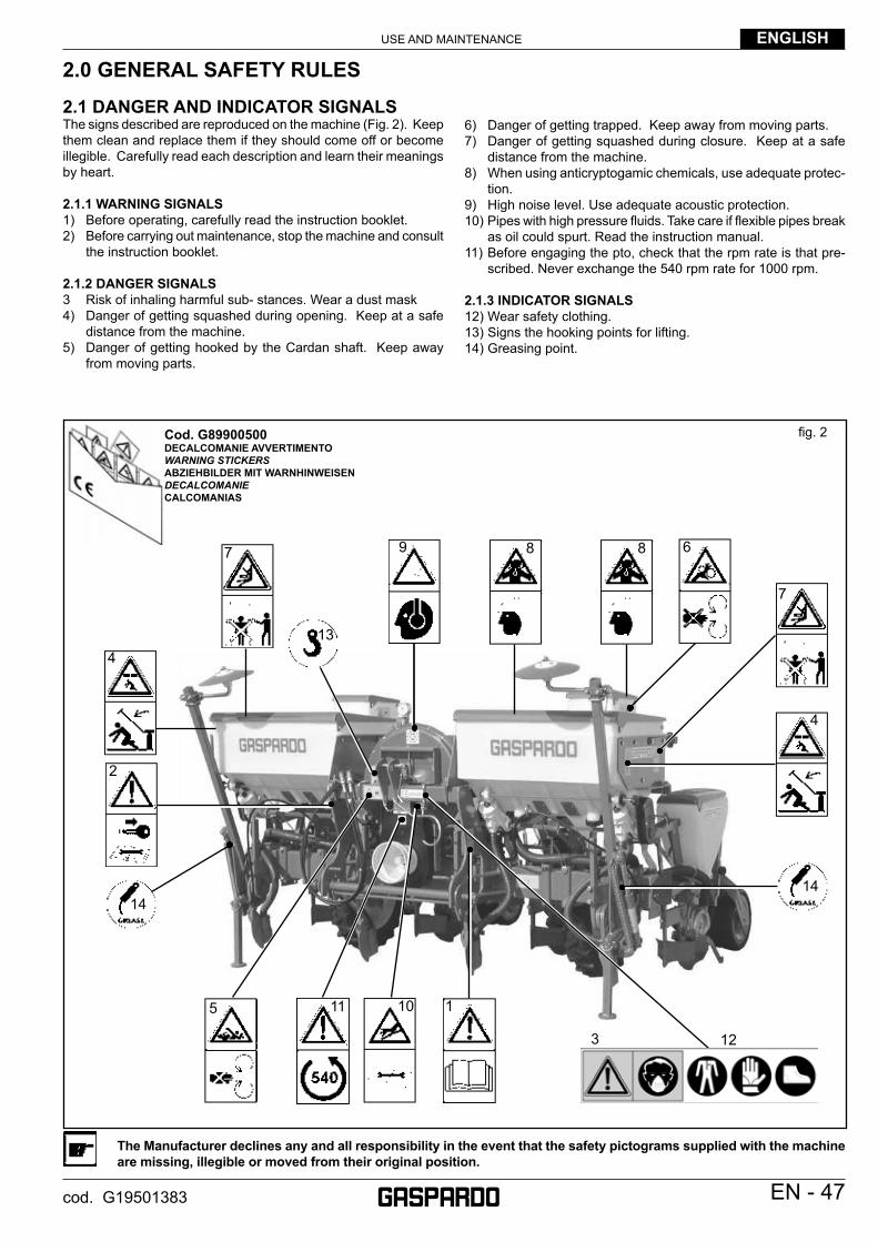
6) Danger of getting trapped. Keep away from moving parts.7) Danger of getting squashed during closure. Keep at a safe
distance from the machine.8) When using anticryptogamic chemicals, use adequate protec-
tion.9) High noise level. Use adequate acoustic protection.10) Pipes with high pressure fl uids. Take care if fl exible pipes break
as oil could spurt. Read the instruction manual.11) Before engaging the pto, check that the rpm rate is that pre-
scribed. Never exchange the 540 rpm rate for 1000 rpm.
2.1.3 INDICATOR SIGNALS12) Wear safety clothing.13) Signs the hooking points for lifting.14) Greasing point.
2.1 DANGER AND INDICATOR SIGNALSThe signs described are reproduced on the machine (Fig. 2). Keep them clean and replace them if they should come off or become illegible. Carefully read each description and learn their meanings by heart.
2.1.1 WARNING SIGNALS1) Before operating, carefully read the instruction booklet.2) Before carrying out maintenance, stop the machine and consult
the instruction booklet.
2.1.2 DANGER SIGNALS3 Risk of inhaling harmful sub- stances. Wear a dust mask4) Danger of getting squashed during opening. Keep at a safe
distance from the machine.5) Danger of getting hooked by the Cardan shaft. Keep away
from moving parts.
fi g. 2Cod. G89900500DECALCOMANIE AVVERTIMENTOWARNING STICKERSABZIEHBILDER MIT WARNHINWEISENDECALCOMANIECALCOMANIAS
413
2
14
5 1011 1
4
7
7 9 88 6
14
123
The Manufacturer declines any and all responsibility in the event that the safety pictograms supplied with the machine are missing, illegible or moved from their original position.
USE AND MAINTENANCEENGLISH
48 - EN cod. G19501383
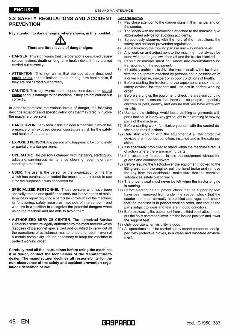
2.2 SAFETY REGULATIONS AND ACCIDENT PREVENTION
Pay attention to danger signs, where shown, in this booklet.
There are three levels of danger signs:
• DANGER: This sign warns that the operations described cause serious lesions, death or long term health risks, if they are not carried out correctly.
• ATTENTION: This sign warns that the operations described could cause serious lesions, death or long term health risks, if they are not carried out correctly.
• CAUTION: This sign warns that the operations described could cause serious damage to the machine. if they are not carried out correctly.
In order to complete the various levels of danger, the following describe situations and specifi c defi nitions that may directly involve the machine or persons.
• DANGER ZONE: any area inside a/o near a machine in which the presence of an exposed person constitutes a risk for the safety and health of that person.
• EXPOSED PERSON: Any person who happens to be completely or partially in a danger zone.
• OPERATOR: The person/s charged with installing, starting up, adjusting, carrying out maintenance, cleaning, repairing or tran-sporting a machine.
• USER: The user is the person or the organization or the fi rm which has purchased or rented the machine and intends to use it for the purposes it was conceived for.
• SPECIALIZED PERSONNEL: Those persons who have been specially trained and qualifi ed to carry out interventions of main-tenance or repair requiring a particular knowledge of the machine, its functioning, safety measures, methods of intervention - and who are in a position to recognize the potential dangers when using the machine and are able to avoid them.
• AUTHORIZED SERVICE CENTER: The authorized Service Center is a structure legally authorized by the manufacturer which disposes of personnel specialized and qualifi ed to carry out all the operations of assistance, maintenance and repair - even of a certain complexity - found necessary to keep the machine in perfect working order.
Carefully read all the instructions before using the machine; if in doubt, contact the technicians of the Manufacturer’s dealer. The manufacturer declines all responsibility for the non-observance of the safety and accident prevention regu-lations described below.
General norms1) Pay close attention to the danger signs in this manual and on
the seeder.2) The labels with the instructions attached to the machine give
abbreviated advice for avoiding accidents.3) Scrupulously observe, with the help of the instructions, the
safety and accident prevention regulations.4) Avoid touching the moving parts in any way whatsoever.5) Any work on and adjustment to the machine must always be
done with the engine switched off and the tractor blocked.6) People or animals must not, under any circumstances be
transported on the equipment.7) It is strictly prohibited to drive the tractor, or allow it to be driven,
with the equipment attached by persons not in possession of a driver’s license, inexpert or in poor conditions of health.
8) Before starting the tractor and the equipment, check that all safety devices for transport and use are in perfect working order.
9) Before starting up the equipment, check the area surrounding the machine to ensure that there are no people, especially children or pets, nearby, and ensure that you have excellent visibility.
10) Use suitable clothing. Avoid loose clothing or garments with parts that could in any way get caught in the rotating or moving parts of the machine.
11) Before starting work, familiarize yourself with the control de-vices and their functions.
12) Only start working with the equipment if all the protective devices are in perfect condition, installed and in the safe po-sition.
13) It is absolutely prohibited to stand within the machine’s radius of action where there are moving parts.
14) It is absolutely forbidden to use the equipment without the guards and container covers.
15) Before leaving the tractor,lower the equipment hooked to the lifting unit, stop the engine, pull the hand brake and remove the key from the dashboard, make sure that the chemical substances safely out of reach.
16) The driver’s seat must never be left when the tractor engine is running.
17) Before starting the equipment, check that the supporting feet have been removed from under the seeder; check that the seeder has been correctly assembled and regulated; check that the machine is in perfect working order, and that all the parts subject to wear and tear are in good condition.
18) Before releasing the equipment from the third point attachment, put the hoist command lever into the locked position and lower the support feet.
19) Only operate when visibility is good.20) All operations must be carried out by expert personnel, equip-
ped with protective gloves, in a clean and dust-free environ-ment.

USE AND MAINTENANCE ENGLISH
EN - 49cod. G19501383
Tractor hitch1) Hook the equipment to a suitable, suffi ciently-powered tractor
by means of the appropriate device (lifter), in conformity with applicable standards.
2) The class of the equipment attachment pins must be the same as that of the lifter attachment.
3) Take care when working within the range of the lifting arms as this is a very dangerous area.
4) Be very careful when hooking and unhooking the equip-ment.
5) It is absolutely forbidden to stand between the tractor and linkage for manoeuvring the lifting controls from the outside (Fig. 6).
6) It is absolutely forbidden to stand in the space between the tractor and the equipment (Fig. 3) with the engine running.
It is possible to work between the tractor and the equipment only after the parking brake has been applied and a suitably sized blocking wedge or stone has been placed under the wheels.
7) The attaching of additional equipment onto the tractor brings about a different distribution of weight on the axles. Check the compatibility of the tractor performance with the weight that the seeder transfers onto the three-point linkage. If in doubt consult the tractor Manufacturer.
8) Comply with the maximum admissible weight for the axle, the total mobile weight, transport regulations and the highway code.
Transport on Road1) When driving on public roads, be sure to follow the highway
code of the country involved.2) Any transport accessories must be provided with suitable signs
and guards.3) It is very important to remember that road holding capacity
as well as direction and braking capacity can be infl uenced, sometimes con-siderably, by equipment being either carried or towed.
4) When negotiating curves, be aware of the variation in centri-fugal force exerted in a position other than that of the center of gravity, with and without the equipment in tow. Also pay greater attention on sloping roads or ground.
5) For transport, adjust and fasten the lateral lifting arm chains of the tractor; check that the seed and fertilizer hopper covers are closed properly; lock the hydraulic lifting control lever; hook the seeders unit following the instructions referring on page 65.
6) Road movements must be performed with all tanks empty.7) For displacements beyond the work area, the equipment must
be placed in the transportation position.
8) Upon request the Manufacturer will supply supports and tables for signaling of dimensions.
9) When the dimensions of carried or partially-carried equipment conceal the tractor’s signalling and lighting devices, these must also be installed on the equipment itself, in conformity with regulations of the highway code of the country involved. When in operation make sure that the lighting system is in perfect working order.
Cardan shaft1) The equipment installed can only be controlled by means of
the Cardan shaft complete with the necessary overload safety devices and guards fastened with the appropriate chain.
2) Only the Cardan shaft supplied by the Manufacturer must be used.
3) The engine must not be running when installing and removing the Cardan shaft.
4) Care must be taken regarding the safety and correct assembly of the Cardan shaft.
5) Use the chain provided to stop the Cardan shaft from rota-ting.
6) Always check carefully that the Cardan shaft guard is always in position, both during trans-portation and operation.
7) Frequently and set intervals check the Cardan shaft guard, it must always be in excellent condition.
8) Before engaging the power take-off, check that the set rpm cor-responds to that indicated by the sticker on the equipment.
9) Before inserting the power take-off, make sure that there are no people or animals nearby and that the rpm selected corresponds to that permitted. Never exceed the maximum admissible speed.
10) Watch out for the rotating universal joint.11) Do not insert the power take-off with the engine off or synchro-
nized with the wheels.12) Always disconnect the power take-off when the Cardan shaft is
at too wide an angle (never more than 10° - Fig. 4) and when it is not being used.
13) Only clean and grease the Cardan shaft when the power take-off is disconnected, the engine is off, the hand brake pulled and the key removed.
14) When not in use, place the Cardan shaft on the support pro-vided for it.
15) After having dismantled the Cardan shaft, place the protective cover on the power take-off shaft again.
fi g. 4fi g. 3
USE AND MAINTENANCEENGLISH
50 - EN cod. G19501383
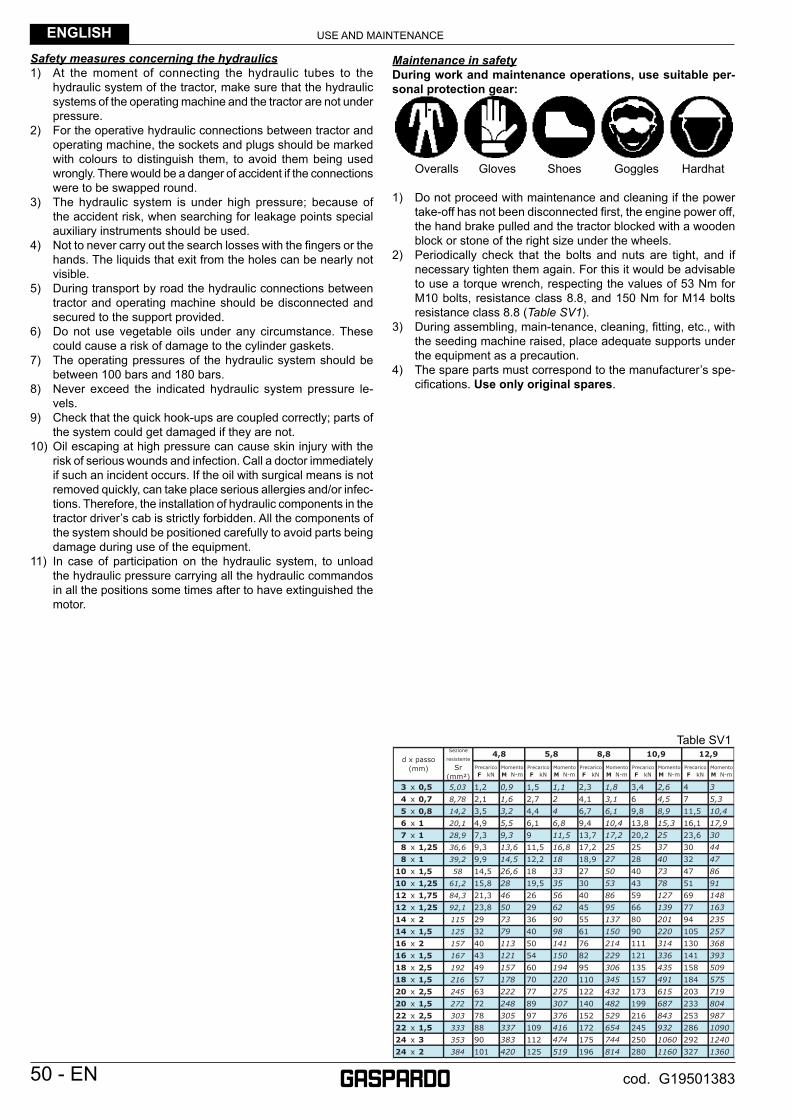
Safety measures concerning the hydraulics1) At the moment of connecting the hydraulic tubes to the
hydraulic system of the tractor, make sure that the hydraulic systems of the operating machine and the tractor are not under pressure.
2) For the operative hydraulic connections between tractor and operating machine, the sockets and plugs should be marked with colours to distinguish them, to avoid them being used wrongly. There would be a danger of accident if the connections were to be swapped round.
3) The hydraulic system is under high pressure; because of the accident risk, when searching for leakage points special auxiliary instruments should be used.
4) Not to never carry out the search losses with the fi ngers or the hands. The liquids that exit from the holes can be nearly not visible.
5) During transport by road the hydraulic connections between tractor and operating machine should be disconnected and secured to the support provided.
6) Do not use vegetable oils under any circumstance. These could cause a risk of damage to the cylinder gaskets.
7) The operating pressures of the hydraulic system should be between 100 bars and 180 bars.
8) Never exceed the indicated hydraulic system pressure le-vels.
9) Check that the quick hook-ups are coupled correctly; parts of the system could get damaged if they are not.
10) Oil escaping at high pressure can cause skin injury with the risk of serious wounds and infection. Call a doctor immediately if such an incident occurs. If the oil with surgical means is not removed quickly, can take place serious allergies and/or infec-tions. Therefore, the installation of hydraulic components in the tractor driver’s cab is strictly forbidden. All the components of the system should be positioned carefully to avoid parts being damage during use of the equipment.
11) In case of participation on the hydraulic system, to unload the hydraulic pressure carrying all the hydraulic commandos in all the positions some times after to have extinguished the motor.
Maintenance in safetyDuring work and maintenance operations, use suitable per-sonal protection gear:
Overalls Gloves Shoes Goggles Hardhat
1) Do not proceed with maintenance and cleaning if the power take-off has not been disconnected fi rst, the engine power off, the hand brake pulled and the tractor blocked with a wooden block or stone of the right size under the wheels.
2) Periodically check that the bolts and nuts are tight, and if necessary tighten them again. For this it would be advisable to use a torque wrench, respecting the values of 53 Nm for M10 bolts, resistance class 8.8, and 150 Nm for M14 bolts resistance class 8.8 (Table SV1).
3) During assembling, main-tenance, cleaning, fi tting, etc., with the seeding machine raised, place adequate supports under the equipment as a precaution.
4) The spare parts must correspond to the manufacturer’s spe-cifi cations. Use only original spares.
Table SV1

USE AND MAINTENANCE ENGLISH
EN - 51cod. G19501383
3.0 DESCRIPTION OF THE SEEDERThis agricultural equipment, called «SP Pneumatic Seeder», can only operate by means of a Cardan shaft applied to the power take-off of an agricultural tractor equipped with a lifting unit, with a three-point universal joint.
The equipment is ‘particularly suitable for precision seeding, for multi-purpose use and on any kind of tilled land . The seeding machine is pneumatically operated and may be equipped with various accessories, such as, for example, a manure spreader, granulate distri-bution, and additional seeding elements.The fundamental concept of the “modularity” has been developed and combined with that of “simplicity”, not only for structure but also for practicality of use.
ATTENTIONThe seeder is suitable only for the uses indicated. The recommended working speed is 6÷8 km/h. The planting unit must only be transported by road with the tanks and hoppers empty and at max speed of 25 km/h. Any other use different from that described in these instructions could cause damage to the machine and represent a serious hazard for the user.This machine has been intended for professional use: it must be operated exclusively by preliminarily educated, trained and authorised operators who hold a regular driving license.
Operating instructions• The machine was manufactured for dosing and distributing commercial seeds of standard quality.• The machine is intended for professional users: operation must be allowed to skilled operators only.• The machine must be operated by one operator only.• The machine is not intended for purposes other than farming applications.
Conforming machine operation also includes:• compliance with all the instructions provided in this manual;• performance of inspection and maintenance operations described in this manual;• exclusive use of genuine GASPARDO spare parts.
The Customer must ensure that Qualifi ed Operators for routine machine operation are suitably trained and prove competent in carrying out the tasks assigned to them, taking care of their safety and that of third parties.Depending on the qualifi cation level and tasks assigned, qualifi ed operators must be duly instructed on the machine functions so as to operate and manage it correctly and guarantee good machine effi ciency.Regular operation depends on the correct use and adequate maintenance of the equipment. It is advisable therefore to observe scru-pulously what is described in order to prevent any inconveniences that could prejudicate proper operation and duration. It is just as important to keep to what is described in this booklet since the Manufacturer declines all responsibility due to negligence and non-observance of these rules. At any rate the Manufacturer is available to assure immediate and accurate technical assistance and all that may be necessary for the improved operation and better performance of the equipment.The machine user shall be liable for damage caused by non-compliance with the instructions hereby.
ATTENTIONThe machine must be operated by qualifi ed operators of the Customer. The operator must wear suitable personal protection equipment (safety footwear, overalls and gloves, etc.).
Precautions for useBelow is a list of precautions for use the machine:• ensure that there are no remarkably big stones or rocks on the soil; • ensure that there are no metal elements of any type whatsoever, but especially nets, cables, wire ropes, chains, pipes, etc. on the soil.
USE AND MAINTENANCEENGLISH
52 - EN cod. G19501383
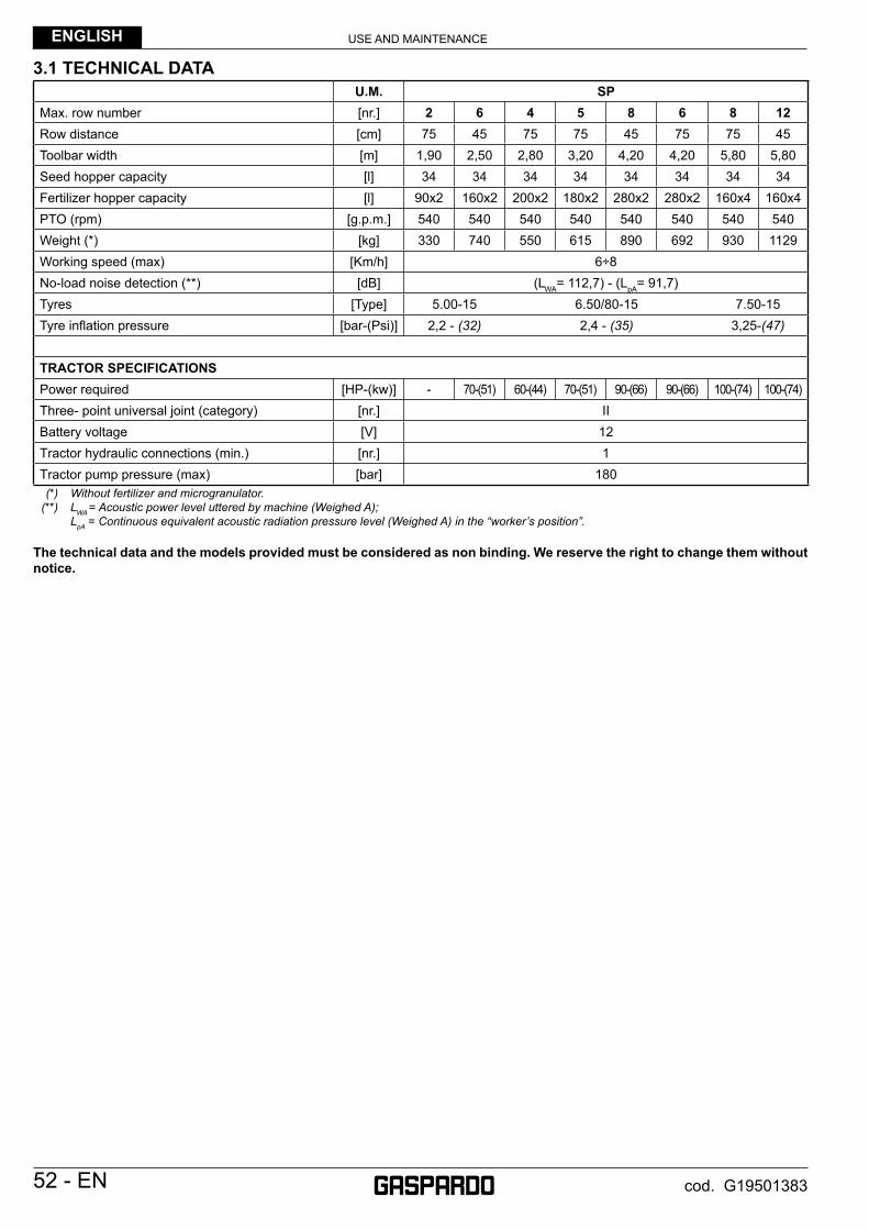
3.1 TECHNICAL DATAU.M. SP
Max. row number [nr.] 2 6 4 5 8 6 8 12Row distance [cm] 75 45 75 75 45 75 75 45Toolbar width [m] 1,90 2,50 2,80 3,20 4,20 4,20 5,80 5,80Seed hopper capacity [l] 34 34 34 34 34 34 34 34Fertilizer hopper capacity [l] 90x2 160x2 200x2 180x2 280x2 280x2 160x4 160x4PTO (rpm) [g.p.m.] 540 540 540 540 540 540 540 540Weight (*) [kg] 330 740 550 615 890 692 930 1129Working speed (max) [Km/h] 6÷8No-load noise detection (**) [dB] (LWA= 112,7) - (LpA= 91,7)Tyres [Type] 5.00-15 6.50/80-15 7.50-15Tyre infl ation pressure [bar-(Psi)] 2,2 - (32) 2,4 - (35) 3,25-(47)
TRACTOR SPECIFICATIONSPower required [HP-(kw)] - 70-(51) 60-(44) 70-(51) 90-(66) 90-(66) 100-(74) 100-(74)Three- point universal joint (category) [nr.] IIBattery voltage [V] 12Tractor hydraulic connections (min.) [nr.] 1Tractor pump pressure (max) [bar] 180
(*) Without fertilizer and microgranulator. (**) LWA = Acoustic power level uttered by machine (Weighed A); LpA = Continuous equivalent acoustic radiation pressure level (Weighed A) in the “worker’s position”.
The technical data and the models provided must be considered as non binding. We reserve the right to change them without notice.
USE AND MAINTENANCE ENGLISH
EN - 53cod. G19501383
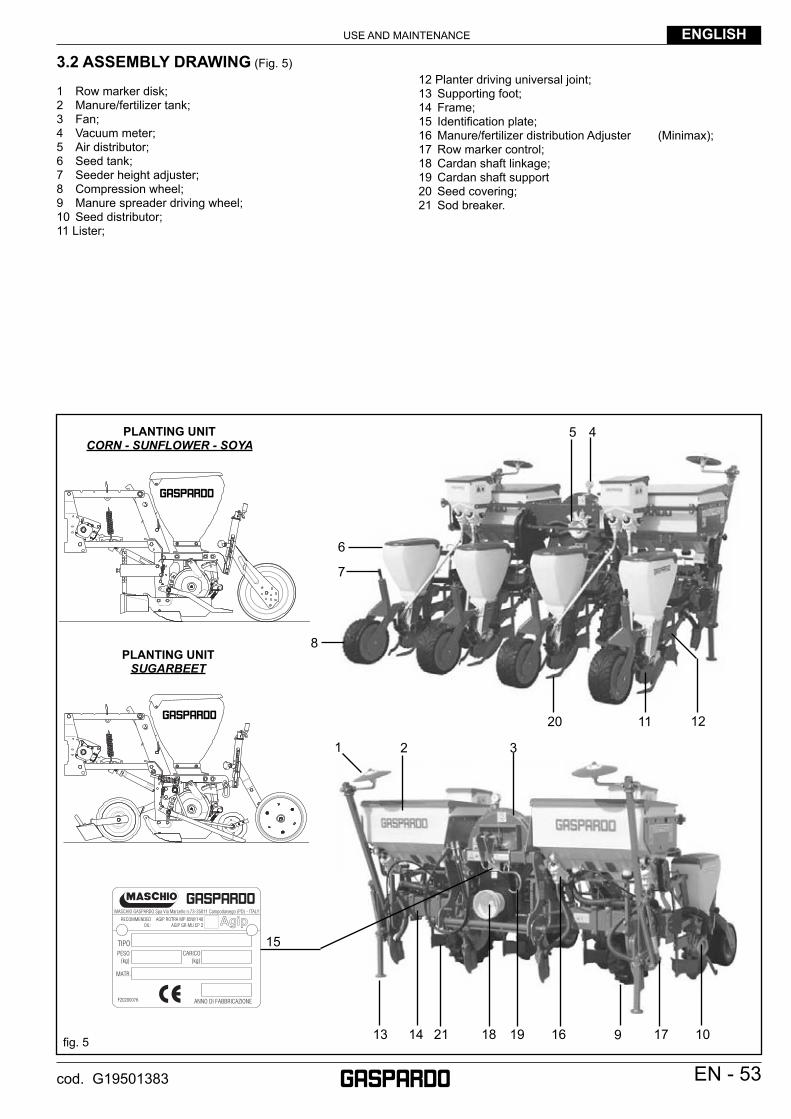
3.2 ASSEMBLY DRAWING (Fig. 5)
1 Row marker disk;2 Manure/fertilizer tank;3 Fan;4 Vacuum meter;5 Air distributor;6 Seed tank;7 Seeder height adjuster;8 Compression wheel;9 Manure spreader driving wheel;10 Seed distributor;11 Lister;
12 Planter driving universal joint;13 Supporting foot;14 Frame;15 Identifi cation plate;16 Manure/fertilizer distribution Adjuster (Minimax);17 Row marker control;18 Cardan shaft linkage;19 Cardan shaft support20 Seed covering;21 Sod breaker.
fi g. 5
15
16 1718 19
20
PLANTING UNIT CORN - SUNFLOWER - SOYA
21
PLANTING UNIT SUGARBEET
913 14
1 2 3
10
6
7
8
45
11 12
USE AND MAINTENANCEENGLISH
54 - EN cod. G19501383
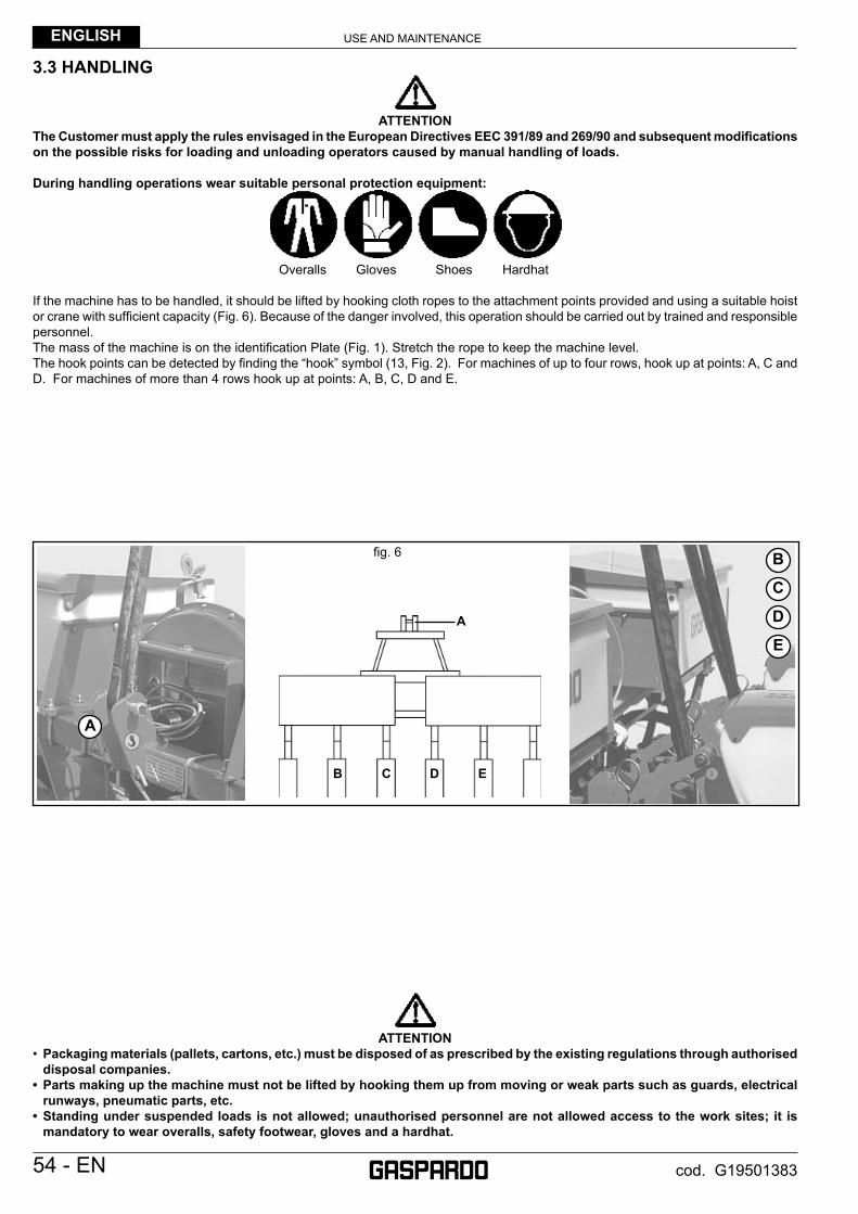
3.3 HANDLING
ATTENTIONThe Customer must apply the rules envisaged in the European Directives EEC 391/89 and 269/90 and subsequent modifi cations on the possible risks for loading and unloading operators caused by manual handling of loads.
During handling operations wear suitable personal protection equipment:
Overalls Gloves Shoes Hardhat
If the machine has to be handled, it should be lifted by hooking cloth ropes to the attachment points provided and using a suitable hoist or crane with suffi cient capacity (Fig. 6). Because of the danger involved, this operation should be carried out by trained and responsible personnel. The mass of the machine is on the identifi cation Plate (Fig. 1). Stretch the rope to keep the machine level.The hook points can be detected by fi nding the “hook” symbol (13, Fig. 2). For machines of up to four rows, hook up at points: A, C and D. For machines of more than 4 rows hook up at points: A, B, C, D and E.
ATTENTION• Packaging materials (pallets, cartons, etc.) must be disposed of as prescribed by the existing regulations through authorised
disposal companies.• Parts making up the machine must not be lifted by hooking them up from moving or weak parts such as guards, electrical
runways, pneumatic parts, etc.• Standing under suspended loads is not allowed; unauthorised personnel are not allowed access to the work sites; it is
mandatory to wear overalls, safety footwear, gloves and a hardhat.
A
B C D E
A
B
C
D
E
fi g. 6
USE AND MAINTENANCE ENGLISH
EN - 55cod. G19501383
fi g. 8
fi g. 9
fi g. 7
1
2 32
3
fi g. 10
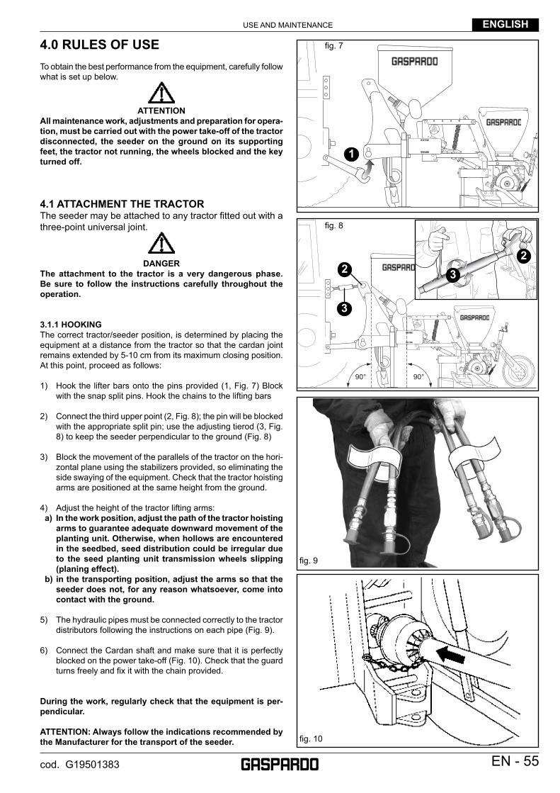
4.0 RULES OF USETo obtain the best performance from the equipment, carefully follow what is set up below.
ATTENTIONAll maintenance work, adjustments and preparation for opera-tion, must be carried out with the power take-off of the tractor disconnected, the seeder on the ground on its supporting feet, the tractor not running, the wheels blocked and the key turned off.
4.1 ATTACHMENT THE TRACTOR The seeder may be attached to any tractor fi tted out with a three-point universal joint.
DANGERThe attachment to the tractor is a very dangerous phase. Be sure to follow the instructions carefully throughout the operation.
3.1.1 HOOKING The correct tractor/seeder position, is determined by placing the equipment at a distance from the tractor so that the cardan joint remains extended by 5-10 cm from its maximum closing position. At this point, proceed as follows:
1) Hook the lifter bars onto the pins provided (1, Fig. 7) Block with the snap split pins. Hook the chains to the lifting bars
2) Connect the third upper point (2, Fig. 8); the pin will be blocked with the appropriate split pin; use the adjusting tierod (3, Fig. 8) to keep the seeder perpendicular to the ground (Fig. 8)
3) Block the movement of the parallels of the tractor on the hori-zontal plane using the stabilizers provided, so eliminating the side swaying of the equipment. Check that the tractor hoisting arms are positioned at the same height from the ground.
4) Adjust the height of the tractor lifting arms: a) In the work position, adjust the path of the tractor hoisting
arms to guarantee adequate downward movement of the planting unit. Otherwise, when hollows are encountered in the seedbed, seed distribution could be irregular due to the seed planting unit transmission wheels slipping (planing effect).
b) in the transporting position, adjust the arms so that the seeder does not, for any reason whatsoever, come into contact with the ground.
5) The hydraulic pipes must be connected correctly to the tractor distributors following the instructions on each pipe (Fig. 9).
6) Connect the Cardan shaft and make sure that it is perfectly blocked on the power take-off (Fig. 10). Check that the guard turns freely and fi x it with the chain provided.
During the work, regularly check that the equipment is per-pendicular.
ATTENTION: Always follow the indications recommended by the Manufacturer for the transport of the seeder.
USE AND MAINTENANCEENGLISH
56 - EN cod. G19501383
4.1.2 UNHOOKING THE SEED DRILL FROM THE TRACTOR
DANGERUnhooking the seed drill from the tractor is a very angerous operation. Great caution must be used and the whole operation must be carried out following the instructions.
For a correct unhooking operation of the seed drill it is necessary to proceed on a horizontal level.
1) Lower the supporting base elements
2) Slowly lower the seed drill until it rests completely on the ground.
3) Disconnect the hydraulic pipes from the tractor distributors and protect the quick couplings with the caps.
4) Sganciare l’albero cardanico dalla trattrice, ed appoggiarlo al gancio predisposto.
5) Loosen and unhook the third point, following the fi rst and se-cond.
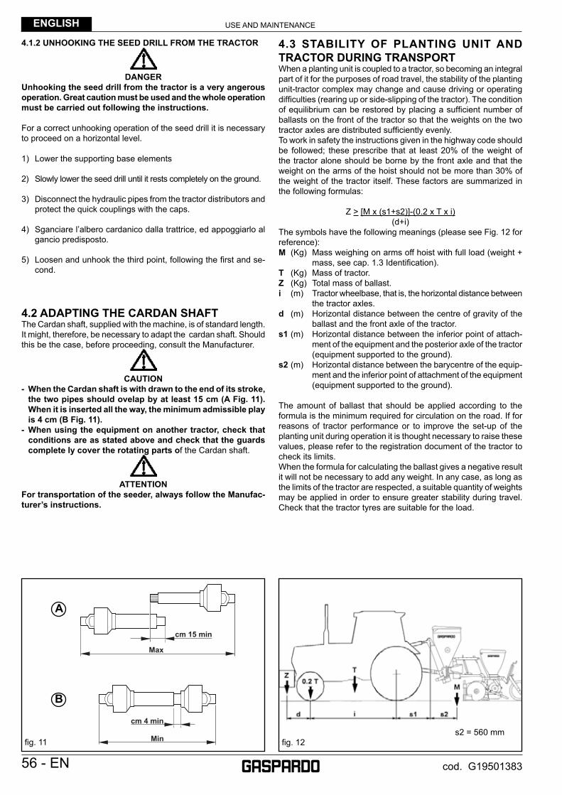
4.2 ADAPTING THE CARDAN SHAFTThe Cardan shaft, supplied with the machine, is of standard length. It might, therefore, be necessary to adapt the cardan shaft. Should this be the case, before proceeding, consult the Manufacturer.
CAUTION- When the Cardan shaft is with drawn to the end of its stroke,
the two pipes should ovelap by at least 15 cm (A Fig. 11). When it is inserted all the way, the minimum admissible play is 4 cm (B Fig. 11).
- When using the equipment on another tractor, check that conditions are as stated above and check that the guards complete ly cover the rotating parts of the Cardan shaft.
ATTENTIONFor transportation of the seeder, always follow the Manufac-turer’s instructions.
4.3 STABILITY OF PLANTING UNIT AND TRACTOR DURING TRANSPORT When a planting unit is coupled to a tractor, so becoming an integral part of it for the purposes of road travel, the stability of the planting unit-tractor complex may change and cause driving or operating diffi culties (rearing up or side-slipping of the tractor). The condition of equilibrium can be restored by placing a suffi cient number of ballasts on the front of the tractor so that the weights on the two tractor axles are distributed suffi ciently evenly.To work in safety the instructions given in the highway code should be followed; these prescribe that at least 20% of the weight of the tractor alone should be borne by the front axle and that the weight on the arms of the hoist should not be more than 30% of the weight of the tractor itself. These factors are summarized in the following formulas:
Z > [M x (s1+s2)]-(0.2 x T x i)(d+i)
The symbols have the following meanings (please see Fig. 12 for reference):M (Kg) Mass weighing on arms off hoist with full load (weight +
mass, see cap. 1.3 Identifi cation).T (Kg) Mass of tractor.Z (Kg) Total mass of ballast.i (m) Tractor wheelbase, that is, the horizontal distance between
the tractor axles.d (m) Horizontal distance between the centre of gravity of the
ballast and the front axle of the tractor.s1 (m) Horizontal distance between the inferior point of attach-
ment of the equipment and the posterior axle of the tractor (equipment supported to the ground).
s2 (m) Horizontal distance between the barycentre of the equip-ment and the inferior point of attachment of the equipment (equipment supported to the ground).
The amount of ballast that should be applied according to the formula is the minimum required for circulation on the road. If for reasons of tractor performance or to improve the set-up of the planting unit during operation it is thought necessary to raise these values, please refer to the registration document of the tractor to check its limits.When the formula for calculating the ballast gives a negative result it will not be necessary to add any weight. In any case, as long as the limits of the tractor are respected, a suitable quantity of weights may be applied in order to ensure greater stability during travel. Check that the tractor tyres are suitable for the load.
s2 = 560 mmfi g. 12
cm 15 min
cm 4 min
Max
Min
A
B
fi g. 11
A
B
USE AND MAINTENANCE ENGLISH
EN - 57cod. G19501383
4.4 TRANSPORTIf it becomes necessary to transport the machine for a long distance, it can be loaded onto a railway wagon or a truck. For this purpose, consult «Technical Data» for weight and specifi c dimensions. The latter are very useful to check the possibility of driving along all types of roads. The machine is generally supplied in a horizontal position with no packing material.It is therefore necessary to use a system of hoisting with a crane and cables, or chains of adequate capacity, hooking onto the machine at the hoisting points marked with the «hook» symbol (13, Fig. 2).
CAUTIONBefore proceeding to the hoisting op- erations, make sure that any any mo- bile elements of the machine are blocked. Make sure to use a crane with an adequate hoisting capacity to lift the machine. Hoist the machine with extreme caution and transfer it slowly, without jerks or abrupt movements.
DANGERThe operations of hoisting and trans- port can be very dangerous if not carried out with the maximum caution; persons not directly involved should be moved away. Clean, evacuate the area and delimit the transfer zone. Check the state, condition and suit- ability of the means at disposition. Do not touch suspended loads, keep- ing them at a safe distance.It most be further ascertained that the operational area is free of obstacles and that there is suffi cient «escape space», mea-ning an area which is free and secure into which one could move rapidly in case a load should fall. The surface on which the machine is to be loaded must be horizontal in or- der to prevent possible shifting.
Once the machine is positioned on the vehicle, make sure that it remains blocked in its position. Fasten the machine on the platform of the vehicle by means of cables suitable for the mass which must be blocked (see «Technical Data» for the weight).The cables must be fi rmly fastened to the machine and pulled taut to the anchorage point on the platform. Once transport has been carried out and before freeing the machine from all its fastenings, make sure that its state and position are such as not to constitute danger. Remove the cables and proceed to unloading with the same means and methods used for loading.
Transit and transporting on the public highwaysWhen driving on the public roads, fi t on the rear refl ector triangles, side lights and fl ashing beacon and always make sure that you comply with the Highway Code and any other applicable regulations.
Make sure that the machine dimensions during transfer phases allow for safe transport when travelling in subways, along narrow roads, near electrical lines, etc..
ATTENTIONThe seed-drill must only be transported by road with the tanks and hoppers empty and at max speed of 25 km/h.Before driving on to the public roads with the machine hitched to the tractor, make sure that the devices listed above and/or the slow vehicle signal and/or the projecting load signal op- erate correctly. These indicators must be affi xed to the rear of the implement in a position where they can be clearly seen by any other vehicle that drives up behind.
The tractor used for transporting the equipment must have the powers shown in the Technical Data table; if necessary, redistribute the total weights with the addition of ballasts to return balance and stability to the whole assembly (page 56).
For displacements beyond the work area, the equipment must be placed in the transportation position:- Lift and hook up the seeding elements (see Chap. 4.6.3).- Where provided for, make all the moving parts come within the transport width, locking them with the safety devices (toolbars, row
marker arms, row marker discs, etc.).- Road movements must be performed with all tanks empty.- Any transport accessories must be provided with suitable signs and guards.
Upon request the Manufacturer will supply supports and tables for signaling of dimensions.
USE AND MAINTENANCEENGLISH
58 - EN cod. G19501383
4.5 SEED SELECTION
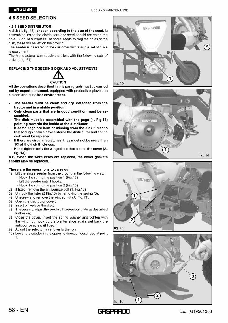
4.5.1 SEED DISTRIBUTORA disk (1, fi g. 13), chosen according to the size of the seed, is assembled inside the distributors (the seed should not enter the hole). Should suction cause some seeds to clog the holes of the disk, these will be left on the ground. The seeder is delivered to the customer with a single set of discs is equipment.The Manufacturer can supply the client with the following sets of disks (pag. 61).
REPLACING THE SEEDING DISK AND ADJUSTMENTS
CAUTIONAll the operations described in this paragraph must be carried out by expert personnel, equipped with protective gloves, in a clean and dust-free environment.
- The seeder must be clean and dry, detached from the tractor and in a stable position.
- Only clean parts that are in good condition must be as-sembled.
- The disk must be assembled with the pegs (1, Fig.14) pointing towards the inside of the distributor.
- If some pegs are bent or missing from the disk it means that foreign bodies have entered the distributor and so the disk must be replaced.
- If there are circular scratches, they must not be more than 1/3 of the disk thickness.
- Hand-tighten only the winged nut that closes the cover (A, fi g. 13).
N.B. When the worn discs are replaced, the cover gaskets should also be replaced.
These are the operations to carry out:1) Lift the single seeder from the ground in the following way: - Hook the spring the position 1 (Fig.15) - Lift the seeder until it hooks, - Hook the spring the position 2 (Fig.15);2) If fi tted, remove the antibounce bolt (1, Fig.16);3) Unhook the lister (2 Fig.16) by removing the spring (3);4) Unscrew and remove the winged nut (A, Fig.13);5) Open the distributor cover;6) Insert or replace the disc;7) If necessary, adjust the seed-spill prevention plate as described
further on;8) Close the cover, insert the spring washer and tighten with
the wing nut, hook up the planter shoe again, put back the antibounce screw (if fi tted);
9) Adjust the selector, as shown further on;10) Lower the seeder in the opposite direction described at point
1.
fi g. 14
fi g. 15
fi g. 16
fi g. 13
1
1
2
3
21
A
1

USE AND MAINTENANCE ENGLISH
EN - 59cod. G19501383
REPLACING THE COVER SEALCheck the whole of the seed distributor cover seal surface regularly (A, Fig. 17) for signs of wear.The seal must be replaced before the surface «A» (Fig. 17), being worn down by the disc movement, reaches surface «B». Also check that no grooves have been made by the disk along surface «A».
EXPELLER DEEDSUse the light grey coloured seed expeller (C, Fig. 18) for small size seeds with an average diameter less than 3.5 mm (e.g. pelleted sugar beet seed).Use the black coloured seed expeller (D, Fig. 18) for medium size seeds with an average diameter from 3.5 to 7 mm (e.g. corn).Remove the seed expellers when using seed with an average diameter greater than 7 mm.Loosen the screws (1, Fig. 18) and remove the expeller (2).
ASSEMBLYPosition the expeller (2) as shown in Figure 18.keeping the expeller pressed against the edge, obtained in the relative seat ( 3, Fig. 18), block it by the screw (1) kit. The screw is to be mounted only as shown in the picture. Do not interpose any thikness between the expeller and its seat. Make sure the expeller is fl at against the seed disk but that it does not come in contact with the disk. Replace the expeller when worn.
SELECTOR ADJUSTMENTA cursor is controlled (1, Fig.19 and 20) by moving the indicator (2, Fig. 19 and 20); this slightly touches the disk near the holes, causing the excess seeds to fall.The selector is adjusted at each change of seed and disk, towards the lower numbers for small seeds (Fig. 19) and vice versa for big seeds (Fig. 20).IMPORTANT: The selector does not adjust the air fl ow in the distributor.
ANTI-OVERFLOW PLATE ADJUSTMENTThe anti-overfl ow plate (1, Fig. 21) can be adjusted to 3 positions and defi nes the width of the seed inlet gap (2, Fig. 21), so that these cannot fl ow out of the distributor due to excessive feeding. Adjustment is par-ticularly needed when the ground slopes steeply or when working with small seeds. In this case, it might be necessary to replace the standard plate with a special one to be used exclusively with small seeds.Spare part order code: 22270133.
fi g. 21
fi g. 19
fi g. 20
fi g. 17
B A
BA
1
2
1
2
1
2
1
2 1
2
3 3
fi g. 18C D

USE AND MAINTENANCEENGLISH
60 - EN cod. G19501383
4.5.2 DISTRIBUTION ADJUSTMENT
SEED CHART Table 2
USE AND MAINTENANCE ENGLISH
EN - 61cod. G19501383
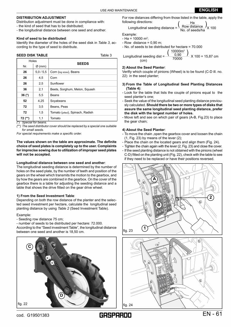
DISTRIBUTION ADJUSTMENTDistribution adjustment must be done in compliance with:- the kind of seed that has to be distributed;- the longitudinal distance between one seed and another.
Kind of seed to be distributed:Identify the diameter of the holes of the seed disk in Table 3, ac-cording to the type of seed to distribute.
SEED DISK TABLE Table 3Holes
SEEDSNr. Ø (mm)
26 5,0 / 5,5 Corn (big sizes), Beans
26 4,5 Corn
26 2,5 Sunfl ower
36 2,1 Beets, Sorghum, Melon, Squash
36 (*) 5,5 Beans
52 4,25 Soyabeans
72 3,5 Beans, Peas
72 1,5 Tomato (pilled), Spinach, Radish
72 (**) 1,1 Tomato(*) Special for beans.(**) The seed distributor cover should be replaced by a special one suitable
for small seeds.For special requirements make a specifi c order.
The values shown on the table are approximate. The defi nite choice of seed plates is completely up to the user. Complaints for imprecise sowing due to utilization of improper seed plates will not be accepted.
Longitudinal distance between one seed and another:The longitudinal seeding distance is determined by the number of holes on the seed plate, by the number of teeth and position of the gears on the wheel which transmits the motion to the gearbox, and by how the gears are combined in the gearbox. On the cover of the gearbox there is a table for adjusting the seeding distance and a table that shows the drive fi tted on the gear drive wheel.
1) From the Seed Investment Table:Depending on both the row distance of the planter and the selec-ted seed investment per hectare, calculate the longitudinal seed planting distance by using Table 2 (Seed Investment Table).
Example:- Seeding row distance 75 cm;- number of seeds to be distributed per hectare: 72.000.According to the “Seed investment Table”, the longitudinal distance between one seed and another is 18,50 cm.
( )HaRow distance X 100No. of seeds/haLongitudinal seeding distance =
( )10000m2
0,90 X 100 = 15,87 cm70000Longitudinal seeding dist =(cm)
fi g. 23
fi g. 24
1
2
A
B
fi g. 22
C
D
For row distances differing from those listed in the table, apply the following directions:
Example:- Ha = 10000 m2;- Row distance = 0,90 m;- No. of seeds to be distributed for hectare = 70.000
2) About the Seed Planter:Verifi y which couple of pinions (Wheel) is to be found (C-D ill. no. 22) in the seed planter;
3) From the Table of Longitudinal Seed Planting Distances (Table 4):
- Look for the table that lists the couple of pinions equal to the seed planter’s one;
- Seek the value of the longitudinal seed planting distance previou-sly calculated. Should there be two or more types of disks that assure the same longitudinal seed planting distance, prefer the disk with the largest number of holes.
- Move left and see on which pair of gears (A-B, Fig.23) to place the gear chain;
4) About the Seed Planter:- To move the chain ,open the gearbox cover and loosen the chain
(1, Fig. 23) by means of the lever (2);- Place the chain on the located gears and align them (Fig. 24).- Tighten the chain again with the lever (2, Fig. 23) and close the cover.- If the seed planting distance is not obtained with the pinions (wheel
C-D) fi tted on the planting unit (Fig. 22), check with the table to see if they need to be replaced or have their positions reversed.
USE AND MAINTENANCEENGLISH
62 - EN cod. G19501383
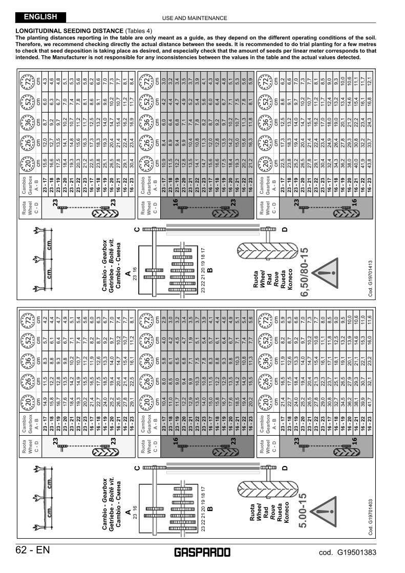
LONGITUDINAL SEEDING DISTANCE (Tables 4)The planting distances reporting in the table are only meant as a guide, as they depend on the different operating conditions of the soil. Therefore, we recommend checking directly the actual distance between the seeds. It is recommended to do trial planting for a few metres to check that seed deposition is taking place as desired, and especially check that the amount of seeds per linear meter corresponds to that intended. The Manufacturer is not responsible for any inconsistencies between the values in the table and the actual values detected.
cmcm
cmcm
cm23
- 17
15,6
12,0
8,7
6,0
4,3
23 -
1816
,612
,79,
26,
34,
623
- 19
17,5
13,5
9,7
6,7
4,8
23 -
2018
,414
,110
,27,
05,
123
- 21
19,3
14,8
10,7
7,4
5,3
23 -
2220
,315
,611
,27,
85,
623
- 23
21,2
16,3
11,7
8,1
5,8
16 -
1722
,517
,312
,58,
66,
216
- 18
23,8
18,3
13,2
9,1
6,6
16 -
1925
,119
,314
,09,
67,
016
- 20
26,5
20,4
14,7
10,2
7,3
16 -
2127
,821
,415
,410
,77,
716
- 22
29,1
22,4
16,2
11,2
8,1
16 -
2330
,423
,416
,911
,78,
4
cmcm
cmcm
cm23
- 17
10,9
8,4
6,0
4,2
3,0
23 -
1811
,58,
96,
44,
43,
223
- 19
12,2
9,4
6,8
4,7
3,4
23 -
2012
,89,
97,
14,
93,
523
- 21
13,5
10,4
7,4
5,2
3,7
23 -
2214
,110
,87,
85,
43,
923
- 23
14,7
11,3
8,2
5,6
4,1
16 -
1715
,612
,08,
76,
04,
316
- 18
16,6
12,8
9,2
6,4
4,6
16 -
1917
,513
,59,
76,
74,
816
- 20
18,4
14,2
10,2
7,1
5,1
16 -
2119
,315
,010
,77,
55,
316
- 22
20,2
15,6
11,3
7,8
5,6
16 -
2321
,216
,311
,88,
15,
9
cmcm
cmcm
cm23
- 17
22,5
17,3
12,5
8,6
6,2
23 -
1823
,818
,313
,29,
16,
623
- 19
25,2
19,4
14,0
9,7
7,0
23 -
2026
,520
,414
,710
,27,
323
- 21
27,8
21,4
15,4
10,7
7,7
23 -
2229
,122
,416
,211
,28,
123
- 23
30,4
23,4
17,0
11,7
8,5
16 -
1732
,424
,918
,012
,49,
016
- 18
34,3
26,4
19,0
13,2
9,3
16 -
1936
,227
,820
,113
,410
,016
- 20
38,0
29,3
21,2
14,6
10,6
16 -
2140
,030
,822
,215
,411
,116
- 22
41,9
32,2
23,4
16,1
11,7
16 -
2343
,833
,724
,316
,812
,1
Cam
bio
Gea
rbox
A
- B
Ruo
ta
Whe
el
C
- D
Cam
bio
Gea
rbox
A
- B
Ruo
ta
Whe
el
C
- D
Cam
bio
Gea
rbox
A
- B
Ruo
ta
Whe
el
C
- D
2026
3652
72
2026
3652
72
2026
3652
72
2026
3652
72
2026
3652
72
C D
A23
16
Cod
. G19
7014
13
Ruo
taW
heel
R
adR
oue
Rue
daКо
лесо
23 2
2 21
20
19 1
8 17
B
Cam
bio
-Gea
rbox
Get
riebe
-B
oitê
vit.
C
ambi
o -С
мена
23
23
23
16
16
23
6,50
/80-
15
cmcm
cmcm
cm23
- 17
14,9
11,5
8,3
5,7
4,2
23 -
1815
,812
,28,
86,
14,
423
- 19
16,7
12,8
9,3
6,4
4,7
23 -
2017
,613
,59,
86,
74,
923
- 21
18,4
14,2
10,2
7,1
5,1
23 -
2219
,314
,910
,77,
45,
423
- 23
20,2
15,5
11,2
7,7
5,6
16 -
1721
,416
,511
,98,
26,
016
- 18
22,7
17,5
12,6
8,7
6,3
16 -
1924
,018
,513
,39,
26,
716
- 20
25,2
19,4
14,0
9,7
7,0
16 -
2126
,520
,414
,710
,27,
416
- 22
27,8
21,4
15,4
10,7
7,7
16 -
2329
,122
,516
,111
,28,
1
cmcm
cmcm
cm23
- 17
10,4
8,0
5,8
4,0
2,9
23 -
1811
,08,
56,
14,
23,
023
- 19
11,7
9,0
6,5
4,5
3,2
23 -
2012
,29,
46,
84,
73,
423
- 21
12,9
9,9
7,1
1,9
3,5
23 -
2213
,510
,37,
55,
13,
723
- 23
14,0
10,8
7,8
5,4
3,9
16 -
1715
,011
,58,
35,
74,
116
- 18
15,8
12,2
8,8
6,1
4,4
16 -
1916
,712
,99,
36,
44,
616
- 20
17,6
13,5
9,8
6,7
4,9
16 -
2118
,514
,210
,37,
15,
116
- 22
19,4
14,9
10,8
7,4
5,4
16 -
2320
,215
,511
,37,
75,
6
cmcm
cmcm
cm23
- 17
21,4
16,5
11,9
8,2
5,9
23 -
1822
,717
,512
,68,
76,
323
- 19
24,0
18,4
13,3
9,2
6,6
23 -
2025
,219
,414
,09,
77,
023
- 21
26,5
20,4
14,7
10,2
7,3
23 -
2227
,821
,315
,410
,67,
723
- 23
29,0
22,3
16,1
11,1
8,0
16 -
1730
,823
,717
,111
,88,
516
- 18
32,7
25,1
18,1
12,5
9,0
16 -
1934
,526
,519
,113
,29,
516
- 20
36,2
27,9
20,1
13,9
10,0
16 -
2138
,129
,321
,114
,610
,616
- 22
39,9
30,7
22,1
15,3
11,0
16 -
2341
,732
,123
,216
,011
,6
Ruo
ta
Whe
el
C
- D
Cam
bio
Gea
rbox
A
- B
Ruo
ta
Whe
el
C
- D
Cam
bio
Gea
rbox
A
- B
Ruo
ta
Whe
el
C
- D
Cam
bio
Gea
rbox
A
- B20
2636
5272
2026
3652
72
2026
3652
72
2026
3652
72
2026
3652
72
C D
A23
16
Cod
. G19
7014
03
Ruo
taW
heel
R
adR
oue
Rue
daКо
лесо
23 2
2 21
20
19 1
8 17
B
5.00
-15
Cam
bio
-Gea
rbox
Get
riebe
-B
oitê
vit.
C
ambi
o -С
мена
23
23
23
16
16
23
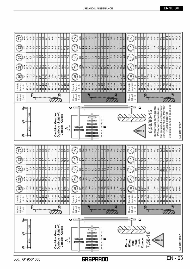
USE AND MAINTENANCE ENGLISH
EN - 63cod. G19501383
cmcm
cmcm
cm23
- 17
17,5
13,5
9,7
6,7
4,9
23 -
1818
,514
,310
,37,
15,
223
- 19
19,6
15,1
10,9
7,5
5,4
23 -
2020
,615
,911
,47,
95,
723
- 21
21,6
16,6
12,0
8,3
6,0
23 -
2222
,717
,412
,68,
76,
323
- 23
23,7
18,2
13,2
9,1
6,6
16 -
1725
,219
,414
,09,
77,
016
- 18
26,7
20,5
14,8
10,3
7,4
16 -
1928
,121
,615
,610
,87,
816
- 20
29,6
22,8
16,5
11,4
8,2
16 -
2131
,123
,917
,312
,08,
616
- 22
32,6
25,1
18,1
12,5
9,1
16 -
2334
,126
,218
,913
,19,
5
cmcm
cmcm
cm23
- 17
12,2
9,4
6,8
4,7
3,4
23 -
1812
,99,
97,
25,
03,
623
- 19
13,6
10,5
7,6
5,2
3,8
23 -
2014
,311
,08,
05,
54,
023
- 21
15,1
11,6
8,4
5,8
4,2
23 -
2215
,812
,18,
86,
14,
423
- 23
16,5
12,7
9,2
6,3
4,6
16 -
1717
,513
,59,
76,
74,
916
- 18
18,5
14,3
10,3
7,1
5,2
16 -
1919
,615
,110
,97,
55,
416
- 20
20,6
15,9
11,4
7,9
5,7
16 -
2121
,616
,612
,08,
36,
016
- 22
22,7
17,4
12,6
8,7
6,3
16 -
2323
,718
,213
,29,
16,
6
cmcm
cmcm
cm23
- 17
25,2
19,4
14,0
9,7
7,0
23 -
1826
,720
,514
,810
,37,
423
- 19
28,1
21,6
15,6
10,8
7,8
23 -
2029
,622
,816
,511
,48,
223
- 21
31,1
23,9
17,3
12,0
8,6
23 -
2232
,625
,118
,112
,59,
123
- 23
34,1
26,2
18,9
13,1
9,5
16 -
1736
,227
,820
,113
,910
,116
- 18
38,3
29,5
21,3
14,7
10,6
16 -
1940
,531
,122
,515
,611
,216
- 20
42,6
32,8
23,7
16,4
11,8
16 -
2144
,734
,424
,817
,212
,416
- 22
46,8
36,0
26,0
18,0
13,0
16 -
2349
,037
,727
,218
,813
,6
Ruo
ta
Whe
el
C
- D
Cam
bio
Gea
rbox
A
- B
Ruo
ta
Whe
el
C
- D
Cam
bio
Gea
rbox
A
- B
Ruo
ta
Whe
el
C
- D
Cam
bio
Gea
rbox
A
- B20
2636
5272
2026
3652
72
2026
3652
72
2026
3652
72
2026
3652
72
C D
A23
16
Cod
. G19
7014
52
Ruo
taW
heel
R
adR
oue
Rue
daКо
лесо
23 2
2 21
20
19 1
8 17
B
Cam
bio
-Gea
rbox
Get
riebe
-B
oitê
vit.
C
ambi
o -С
мена
23
23
23
16
16
23
7,50
-16
cmcm
cmcm
cm23
- 17
16,3
12,5
9,0
6,3
4,5
23 -
1817
,213
,29,
66,
64,
823
- 19
18,2
14,0
10,1
7,0
5,0
23 -
2019
,114
,710
,67,
45,
323
- 21
20,1
15,5
11,2
7,7
5,6
23 -
2221
,016
,211
,78,
15,
823
- 23
22,0
16,9
12,2
8,5
6,1
16 -
1723
,418
,013
,09,
06,
516
- 18
24,8
19,0
13,8
9,5
6,9
16 -
1926
,120
,114
,510
,07,
316
- 20
27,5
21,2
15,3
10,6
7,6
16 -
2128
,922
,216
,011
,18,
016
- 22
30,3
23,3
16,8
11,6
8,4
16 -
2331
,624
,317
,612
,28,
8
cmcm
cmcm
cm23
- 17
11,3
8,7
6,3
4,4
3,1
23 -
1812
,09,
26,
74,
63,
323
- 19
12,6
9,7
7,0
4,9
3,5
23 -
2013
,310
,27,
45,
13,
723
- 21
14,0
10,7
7,8
5,4
3,9
23 -
2214
,611
,38,
15,
64,
123
- 23
15,3
11,8
8,5
5,9
4,3
16 -
1716
,312
,59,
06,
34,
516
- 18
17,2
13,2
9,6
6,6
4,8
16 -
1918
,214
,010
,17,
05,
016
- 20
19,1
14,7
10,6
7,4
5,3
16 -
2120
,115
,511
,27,
75,
616
- 22
21,0
16,2
11,7
8,1
5,8
16 -
2322
,016
,912
,28,
86,
1
cmcm
cmcm
cm23
- 17
23,4
18,0
13,0
9,0
6,5
23 -
1824
,819
,013
,89,
56,
923
- 19
26,1
20,1
14,5
10,0
7,3
23 -
2027
,521
,215
,310
,67,
623
- 21
28,9
22,2
16,0
11,1
8,0
23 -
2230
,323
,316
,811
,68,
423
- 23
31,6
24,3
17,6
12,2
8,8
16 -
1733
,625
,818
,712
,99,
316
- 18
35,6
27,4
19,8
13,7
9,9
16 -
1937
,628
,920
,914
,410
,416
- 20
39,5
30,4
22,0
15,2
11,0
16 -
2141
,531
,923
,116
,011
,516
- 22
43,5
33,4
24,2
16,7
12,1
16 -
2345
,535
,025
,317
,512
,6
Cam
bio
Gea
rbox
A
- B
Ruo
ta
Whe
el
C
- D
Cam
bio
Gea
rbox
A
- B
Ruo
ta
Whe
el
C
- D
Cam
bio
Gea
rbox
A
- B
Ruo
ta
Whe
el
C
- D
2026
3652
72
2026
3652
72
2026
3652
72
2026
3652
72
2026
3652
72
C D
A23
16
Cod
. G19
7031
62
23 2
2 21
20
19 1
8 17
B
Cam
bio
-Gea
rbox
Get
riebe
-B
oitê
vit.
C
ambi
o -С
мена
23
23
23
16
16
23
Ruo
ta fu
ori c
arre
ggia
taW
heel
out
whe
elba
seR
ad a
ssue
rhal
b sc
hlep
pers
pur
Rou
e ho
rs v
oie
du tr
acte
urR
ueda
est
erio
rВнешни
е коле
са перед
ачи
6,50
/80-
15
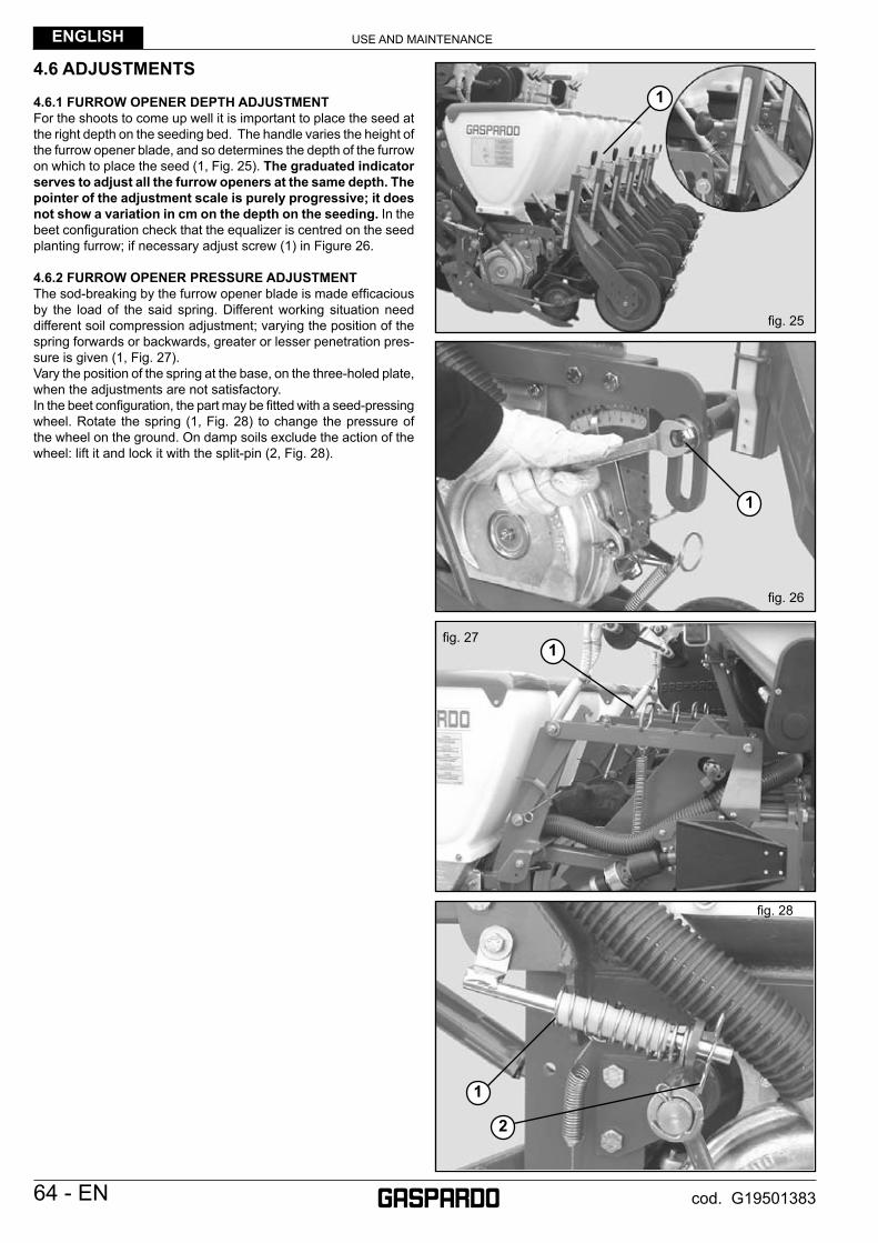
USE AND MAINTENANCEENGLISH
64 - EN cod. G19501383
4.6 ADJUSTMENTS
4.6.1 FURROW OPENER DEPTH ADJUSTMENTFor the shoots to come up well it is important to place the seed at the right depth on the seeding bed. The handle varies the height of the furrow opener blade, and so determines the depth of the furrow on which to place the seed (1, Fig. 25). The graduated indicator serves to adjust all the furrow openers at the same depth. The pointer of the adjustment scale is purely progressive; it does not show a variation in cm on the depth on the seeding. In the beet confi guration check that the equalizer is centred on the seed planting furrow; if necessary adjust screw (1) in Figure 26.
4.6.2 FURROW OPENER PRESSURE ADJUSTMENTThe sod-breaking by the furrow opener blade is made effi cacious by the load of the said spring. Different working situation need different soil compression adjustment; varying the position of the spring forwards or backwards, greater or lesser penetration pres-sure is given (1, Fig. 27).Vary the position of the spring at the base, on the three-holed plate, when the adjustments are not satisfactory.In the beet confi guration, the part may be fi tted with a seed-pressing wheel. Rotate the spring (1, Fig. 28) to change the pressure of the wheel on the ground. On damp soils exclude the action of the wheel: lift it and lock it with the split-pin (2, Fig. 28).
fi g. 25
fi g. 27
fi g. 26
fi g. 28
1
1
1
1
2
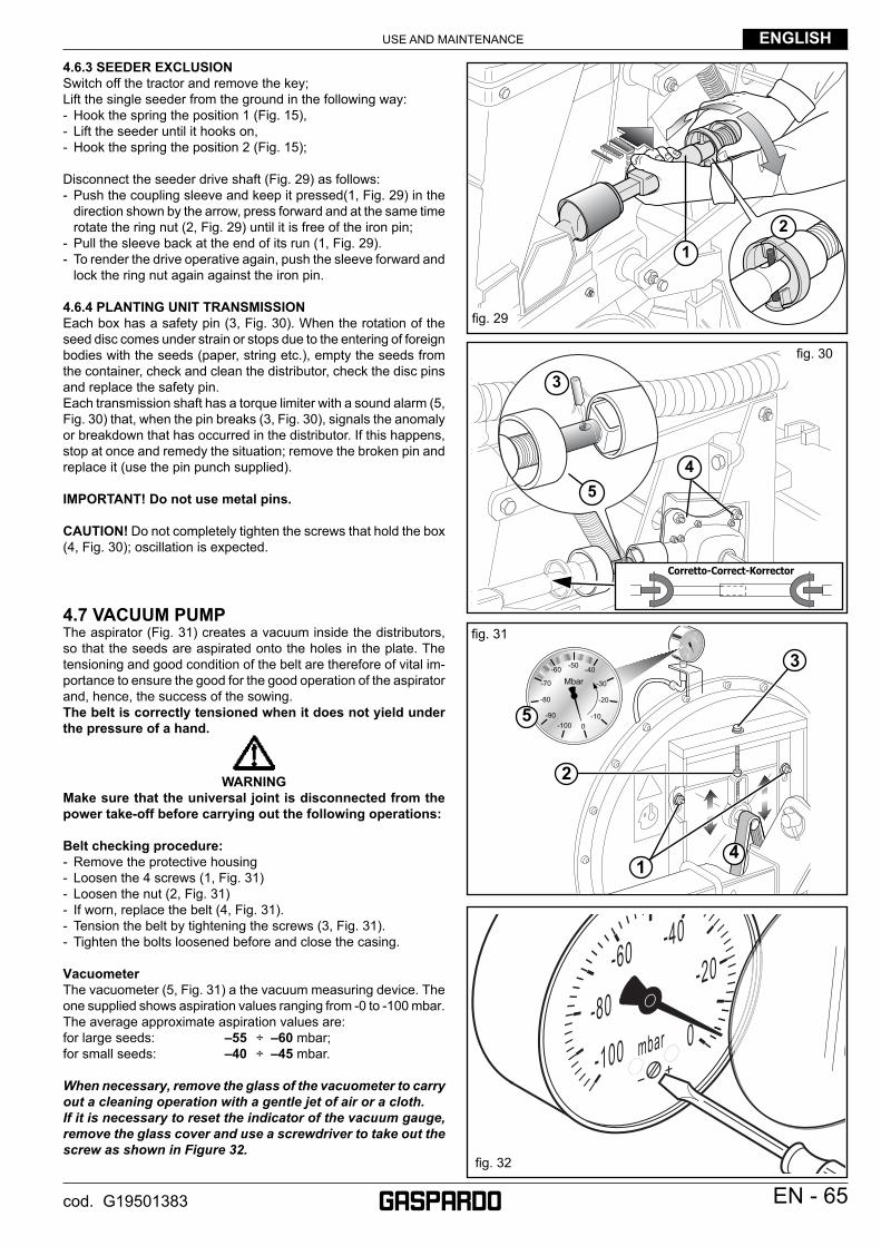
USE AND MAINTENANCE ENGLISH
EN - 65cod. G19501383
4.6.3 SEEDER EXCLUSIONSwitch off the tractor and remove the key;Lift the single seeder from the ground in the following way: - Hook the spring the position 1 (Fig. 15), - Lift the seeder until it hooks on, - Hook the spring the position 2 (Fig. 15);
Disconnect the seeder drive shaft (Fig. 29) as follows:- Push the coupling sleeve and keep it pressed(1, Fig. 29) in the
direction shown by the arrow, press forward and at the same time rotate the ring nut (2, Fig. 29) until it is free of the iron pin;
- Pull the sleeve back at the end of its run (1, Fig. 29).- To render the drive operative again, push the sleeve forward and
lock the ring nut again against the iron pin.
4.6.4 PLANTING UNIT TRANSMISSIONEach box has a safety pin (3, Fig. 30). When the rotation of the seed disc comes under strain or stops due to the entering of foreign bodies with the seeds (paper, string etc.), empty the seeds from the container, check and clean the distributor, check the disc pins and replace the safety pin.Each transmission shaft has a torque limiter with a sound alarm (5, Fig. 30) that, when the pin breaks (3, Fig. 30), signals the anomaly or breakdown that has occurred in the distributor. If this happens, stop at once and remedy the situation; remove the broken pin and replace it (use the pin punch supplied).
IMPORTANT! Do not use metal pins.
CAUTION! Do not completely tighten the screws that hold the box (4, Fig. 30); oscillation is expected.
4.7 VACUUM PUMPThe aspirator (Fig. 31) creates a vacuum inside the distributors, so that the seeds are aspirated onto the holes in the plate. The tensioning and good condition of the belt are therefore of vital im-portance to ensure the good for the good operation of the aspirator and, hence, the success of the sowing. The belt is correctly tensioned when it does not yield under the pressure of a hand.
WARNINGMake sure that the universal joint is disconnected from the power take-off before carrying out the following operations:
Belt checking procedure:- Remove the protective housing- Loosen the 4 screws (1, Fig. 31)- Loosen the nut (2, Fig. 31)- If worn, replace the belt (4, Fig. 31).- Tension the belt by tightening the screws (3, Fig. 31).- Tighten the bolts loosened before and close the casing.
VacuometerThe vacuometer (5, Fig. 31) a the vacuum measuring device. The one supplied shows aspiration values ranging from -0 to -100 mbar. The average approximate aspiration values are: for large seeds: –55 ÷ –60 mbar;for small seeds: –40 ÷ –45 mbar.
When necessary, remove the glass of the vacuometer to carry out a cleaning operation with a gentle jet of air or a cloth.If it is necessary to reset the indicator of the vacuum gauge, remove the glass cover and use a screwdriver to take out the screw as shown in Figure 32.
fi g. 29
Corretto-Correct-Korrector
fi g. 30
12
45
3
fi g. 31
-60
-80
-100 0
-20-40
mbar
fi g. 32
-50-60
-70
-80
-90-100 0
-10
-20
-30
-40
Mbar
1
3
2
4
5
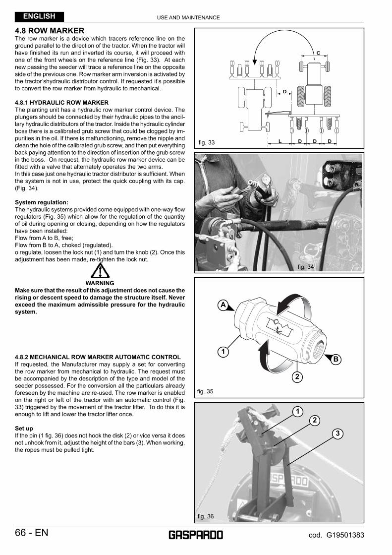
USE AND MAINTENANCEENGLISH
66 - EN cod. G19501383
4.8 ROW MARKERThe row marker is a device which tracers reference line on the ground parallel to the direction of the tractor. When the tractor will have fi nished its run and inverted its course, it will proceed with one of the front wheels on the reference line (Fig. 33). At each new passing the seeder will trace a reference line on the opposite side of the previous one. Row marker arm inversion is activated by the tractor’shydraulic distributor control. If requested it’s possible to convert the row marker from hydraulic to mechanical.
4.8.1 HYDRAULIC ROW MARKERThe planting unit has a hydraulic row marker control device. The plungers should be connected by their hydraulic pipes to the ancil-lary hydraulic distributors of the tractor. Inside the hydraulic cylinder boss there is a calibrated grub screw that could be clogged by im-purities in the oil. If there is malfunctioning, remove the nipple and clean the hole of the calibrated grub screw, and then put everything back paying attention to the direction of insertion of the grub screw in the boss. On request, the hydraulic row marker device can be fi tted with a valve that alternately operates the two arms.In this case just one hydraulic tractor distributor is suffi cient. When the system is not in use, protect the quick coupling with its cap. (Fig. 34).
System regulation:The hydraulic systems provided come equipped with one-way fl ow regulators (Fig. 35) which allow for the regulation of the quantity of oil during opening or closing, depending on how the regulators have been installed:Flow from A to B, free;Flow from B to A, choked (regulated).o regulate, loosen the lock nut (1) and turn the knob (2). Once this adjustment has been made, re-tighten the lock nut.
WARNINGMake sure that the result of this adjustment does not cause the rising or descent speed to damage the structure itself. Never exceed the maximum admissible pressure for the hydraulic system.
4.8.2 MECHANICAL ROW MARKER AUTOMATIC CONTROLIf requested, the Manufacturer may supply a set for converting the row marker from mechanical to hydraulic. The request must be accompanied by the description of the type and model of the seeder possessed. For the conversion all the particulars already foreseen by the machine are re-used. The row marker is enabled on the right or left of the tractor with an automatic control (Fig. 33) triggered by the movement of the tractor lifter. To do this it is enough to lift and lower the tractor lifter once.
Set upIf the pin (1 fi g. 36) does not hook the disk (2) or vice versa it does not unhook from it, adjust the height of the bars (3). When working, the ropes must be pulled tight.
fi g. 36
12
3
fi g. 33
fi g. 35
fi g. 34
L
D
C
D D D
1
2
A
B
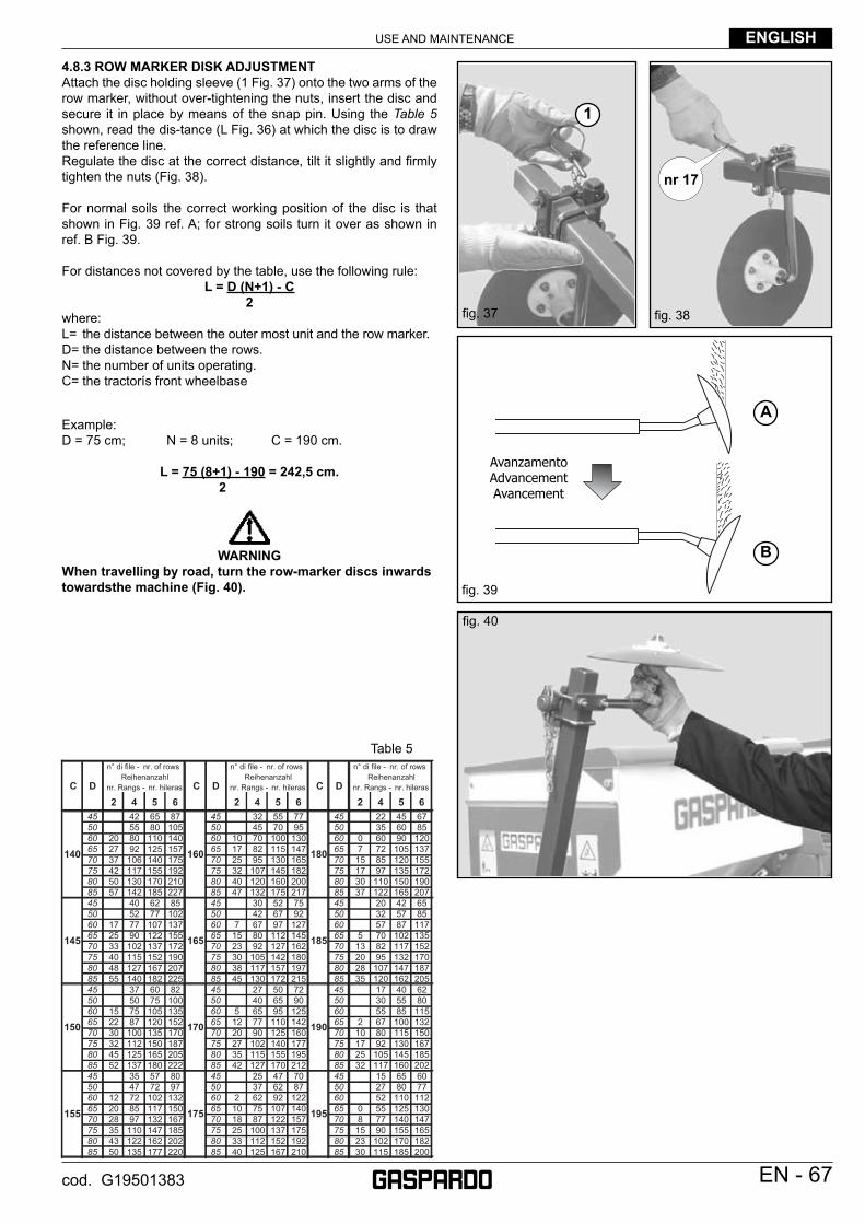
USE AND MAINTENANCE ENGLISH
EN - 67cod. G19501383
4.8.3 ROW MARKER DISK ADJUSTMENTAttach the disc holding sleeve (1 Fig. 37) onto the two arms of the row marker, without over-tightening the nuts, insert the disc and secure it in place by means of the snap pin. Using the Table 5 shown, read the dis-tance (L Fig. 36) at which the disc is to draw the reference line. Regulate the disc at the correct distance, tilt it slightly and fi rmly tighten the nuts (Fig. 38).
For normal soils the correct working position of the disc is that shown in Fig. 39 ref. A; for strong soils turn it over as shown in ref. B Fig. 39.
For distances not covered by the table, use the following rule:L = D (N+1) - C
2where:L= the distance between the outer most unit and the row marker.D= the distance between the rows.N= the number of units operating.C= the tractorís front wheelbase
Example:D = 75 cm; N = 8 units; C = 190 cm.
L = 75 (8+1) - 190 = 242,5 cm. 2
WARNINGWhen travelling by road, turn the row-marker discs inwards towardsthe machine (Fig. 40).
fi g. 40
fi g. 39
AvanzamentoAdvancementAvancement
nr 17
fi g. 38fi g. 37
Table 5
1
A
B
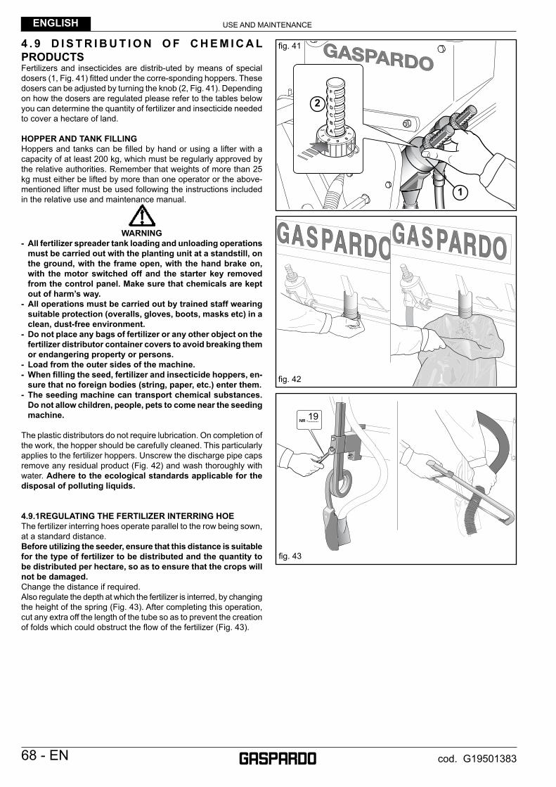
USE AND MAINTENANCEENGLISH
68 - EN cod. G19501383
4 . 9 D I S T R I B U T I O N O F C H E M I C A L PRODUCTSFertilizers and insecticides are distrib-uted by means of special dosers (1, Fig. 41) fi tted under the corre-sponding hoppers. These dosers can be adjusted by turning the knob (2, Fig. 41). Depending on how the dosers are regulated please refer to the tables below you can determine the quantity of fertilizer and insecticide needed to cover a hectare of land.
HOPPER AND TANK FILLING Hoppers and tanks can be fi lled by hand or using a lifter with a capacity of at least 200 kg, which must be regularly approved by the relative authorities. Remember that weights of more than 25 kg must either be lifted by more than one operator or the above-mentioned lifter must be used following the instructions included in the relative use and maintenance manual.
WARNING- All fertilizer spreader tank loading and unloading operations
must be carried out with the planting unit at a standstill, on the ground, with the frame open, with the hand brake on, with the motor switched off and the starter key removed from the control panel. Make sure that chemicals are kept out of harm’s way.
- All operations must be carried out by trained staff wearing suitable protection (overalls, gloves, boots, masks etc) in a clean, dust-free environment.
- Do not place any bags of fertilizer or any other object on the fertilizer distributor container covers to avoid breaking them or endangering property or persons.
- Load from the outer sides of the machine.- When fi lling the seed, fertilizer and insecticide hoppers, en-
sure that no foreign bodies (string, paper, etc.) enter them.- The seeding machine can transport chemical substances.
Do not allow children, people, pets to come near the seeding machine.
The plastic distributors do not require lubrication. On completion of the work, the hopper should be carefully cleaned. This particularly applies to the fertilizer hoppers. Unscrew the discharge pipe caps remove any residual product (Fig. 42) and wash thoroughly with water. Adhere to the ecological standards applicable for the disposal of polluting liquids.
4.9.1REGULATING THE FERTILIZER INTERRING HOEThe fertilizer interring hoes operate parallel to the row being sown, at a standard distance. Before utilizing the seeder, ensure that this distance is suitable for the type of fertilizer to be distributed and the quantity to be distributed per hectare, so as to ensure that the crops will not be damaged.Change the distance if required. Also regulate the depth at which the fertilizer is interred, by changing the height of the spring (Fig. 43). After completing this operation, cut any extra off the length of the tube so as to prevent the creation of folds which could obstruct the fl ow of the fertilizer (Fig. 43).
11 1
NR -.........19
fi g. 41
fi g. 43
fi g. 42
1
2

USE AND MAINTENANCE ENGLISH
EN - 69cod. G19501383
4.9.2 SPEEDY SETThe fertilizer spreader hopper can be equipped with the SPEEDY SET (Fig. 44), which allows the MINIMAX volume batchers (properly modifi ed) to be adjusted on each hopper with just one operation.Regularly check that the sliding hatches are aligned.The distribution table suitable for this adjustment is shown further on.
4.9.3 FERTILIZER DISTRIBUTOR - Table of distribution quantity in kg/Ha
CAUTION: the MINIMAX batcher, adjusted to the fi rst positions (B0÷C0 or 1÷1.5 with SPEEDY SET) may become clogged because of the small opening, especially if fertilizers with irregular grain size are used. If the quantity of fertilizer to be delivered comes within the fi rst positions (darkened lines on the table) get in touch with the manufacturer. The fi gures given in the table are approximate as the specifi c weight and size of the grains often vary. In any case, always refer to the specifi c weight shown on the product packaging; if this is not given, get in touch with the manufacturer. For specifi c weights that are different to those shown in the tables, get in touch with Maschio Gaspardo S.p.A.
45 cm 50 cm 60 cm 70 cm 75 cm 80 cm 70 cm 75 cm 80 cm
0,8 1 1,2 0,8 1 1,2 0,8 1 1,2 0,8 1 1,2 0,8 1 1,2 0,8 1 1,2 0,8 1 1,2 0,8 1 1,2 0,8 1 1,2B-0 55 69 83 50 62 75 41 52 62 35 44 53 33 41 50 31 39 47 B-0 64 80 96 60 75 89 56 70 84B-5 81 102 122 73 92 110 61 76 92 52 65 78 49 61 73 46 57 69 B-5 94 118 141 88 110 132 82 103 124C-0 107 134 161 97 121 145 81 101 121 69 86 104 64 81 97 60 76 91 C-0 124 155 187 116 145 174 109 136 163C-5 137 171 205 123 154 184 102 128 154 88 110 132 82 102 123 77 96 115 C-5 158 197 237 147 184 221 138 173 207D-0 163 203 244 146 183 220 122 153 183 105 131 157 98 122 146 92 114 137 D-0 188 235 282 176 220 264 165 206 247D-5 189 236 283 170 212 255 142 177 212 121 152 182 113 142 170 106 133 159 D-5 218 273 328 204 255 306 191 239 287E-0 215 269 322 193 242 290 161 202 242 138 173 207 129 161 193 121 151 181 E-0 249 311 373 232 290 348 218 272 326E-5 244 305 366 220 275 329 183 229 275 157 196 235 146 183 220 137 172 206 E-5 282 353 424 264 329 395 247 309 371F-0 270 338 405 243 304 365 203 253 304 174 217 261 162 203 243 152 190 228 F-0 313 391 469 292 365 438 274 342 410F-5 296 370 444 267 333 400 222 278 333 190 238 286 178 222 267 167 208 250 F-5 343 429 514 320 400 480 300 375 450G-0 325 407 488 293 366 439 244 305 366 209 261 314 195 244 293 183 229 275 G-0 376 471 565 351 439 527 329 412 494G-5 351 439 527 316 395 475 264 330 395 226 282 339 211 264 316 198 247 297 G-5 407 508 610 380 475 569 356 445 534
G-10 378 472 566 340 425 510 283 354 425 243 303 364 227 283 340 212 266 319 G-10 437 546 655 408 510 612 382 478 574
Cod. 19700822
Interfila - Row spacing - ReihenabstandDistance entre les lignes - Distancia entre las hileras
Peso specifico - Specific weight - Spezifisches Gewicht Poids specifique - Peso especifico : Kg/dm‡
Posizione regolazione distributore - Position of distributor adjustmentEinstellung Einstellvorrchtung - Position reglage distributeur - Posici n regulaci n distribuidor
Interfila - Row spacing - ReihenabstandDistance entre les lignes - Distancia entre las hileras
Peso specifico - Specific weight - Spezifisches Gewicht Poids specifique - Peso especifico : Kg/dm‡
Posizione regolazione distributore - Position of distributor adjustment - Einstellung Einstellvorrchtung - Position reglage distributeur Posici n regulaci n distribuidor
Spandiconcime - Tabella di distribuzione
Fertilizer - Distribution table D ngerstreuer - D ngermengetabelle
Espandeur d’engrais - Tableaux de distribution Abonadora - Prospectos de distribuci n
(*) Con ruote da 6.50/80 R15 diminuire i valori della tabella del 4%. Con ruote 7.50 R16 diminuire i valori della tabella del 20%.(*) With 6.50/80 R15 wheels decrease distribution quantity by 4% . With 7.50 R16 wheels decrease by 20% .(*) Mit Bereifung 6.50/80 R15 die Mengen der Tabelle um 4% vermindern. Mit Bereifung 7.50 R16 die Mengen der Tabelle um 20% vermindern.(*) Avec roues de 6.50/80 R15 diminuer les donnØes du tableau de 4% . Avec roues de 7.50 R16 diminuer de 20% .(*) Con ruedas 6.50/80 R15 disminuir los valores de la tabla del 4%. Con ruedas 7.50 R16 disminuir los mismo del 20%.
I valori della tabella costituiscono solo valori indicativi, in quanto il peso specifico e la grandezza dei granelli sono spesso diversi. - The chart values are only approximate, since the specificweight and the size of the granules often differ . - Die Tabellenwerte sind Richtwerte, da das spezifische Gewicht und die Gr e der K rner oft unterschiedlich sind. - Les valeurs indiquØessur le tableau de rØglagecostituent simplement des valeurs donnØes titre indicatif car le poids spØcifiqueet la grandeur des grains sont souvement diffØrents. - Los valores de la tabla sons lo indicativos, ya que el peso espec fico y las dimensiones de los granos son, generalmente, diferentes.
Z30
Z20Trasmissione ruota motriceTransmission drive wheelbersetzung d entrainemet
Transmision roue motriceTransmici n de la rueda motriz
Z20
Z10
Z25Z20
Z20
Z15
Trasmissione ruota motriceTransmission drive wheelbersetzung d entrainemet
Transmision roue motriceTransmici n de la rueda motriz5.00/80
R15 (*)5.00/80 R15 (*)
MASCHIO GASPARDO S.p.A.
fi g. 44

USE AND MAINTENANCEENGLISH
70 - EN cod. G19501383
4.9.4 SPEEDY SET
M
AS
CH
IO G
AS
PA
RD
O S
.p.A
.
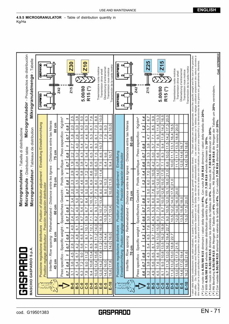
USE AND MAINTENANCE ENGLISH
EN - 71cod. G19501383
4.9.5 MICROGRANULATOR - Table of distribution quantity in Kg/Ha
MA
SC
HIO
GA
SP
AR
DO
S.p
.A.
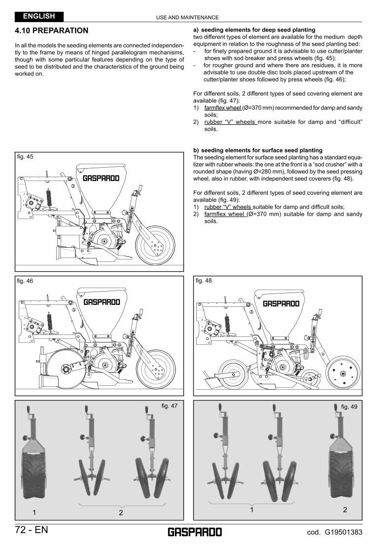
USE AND MAINTENANCEENGLISH
72 - EN cod. G19501383
4.10 PREPARATION
In all the models the seeding elements are connected independen-tly to the frame by means of hinged parallelogram mechanisms, though with some particular features depending on the type of seed to be distributed and the characteristics of the ground being worked on.
a) seeding elements for deep seed plantingtwo different types of element are available for the medium depth equipment in relation to the roughness of the seed planting bed:- for fi nely prepared ground it is advisable to use cutter/planter
shoes with sod breaker and press wheels (fi g. 45);- for rougher ground and where there are residues, it is more advisable to use double disc tools placed upstream of the cutter/planter shoes followed by press wheels (fi g. 46);
For different soils, 2 different types of seed covering element are available (fi g. 47):1) farmfl ex wheel (Ø=370 mm) recommended for damp and sandy
soils;2) rubber “V” wheels more suitable for damp and “difficult”
soils.
b) seeding elements for surface seed plantingThe seeding element for surface seed planting has a standard equa-lizer with rubber wheels: the one at the front is a “sod crusher” with a rounded shape (having Ø=280 mm), followed by the seed pressing wheel, also in rubber, with independent seed coverers (fi g. 48).
For different soils, 2 different types of seed covering element are available (fi g. 49):1) rubber “V” wheels suitable for damp and diffi cult soils;2) farmfl ex wheel (Ø=370 mm) suitable for damp and sandy
soils.
fi g. 47
21 1 2
fi g. 49
fi g. 46
fi g. 45
fi g. 48
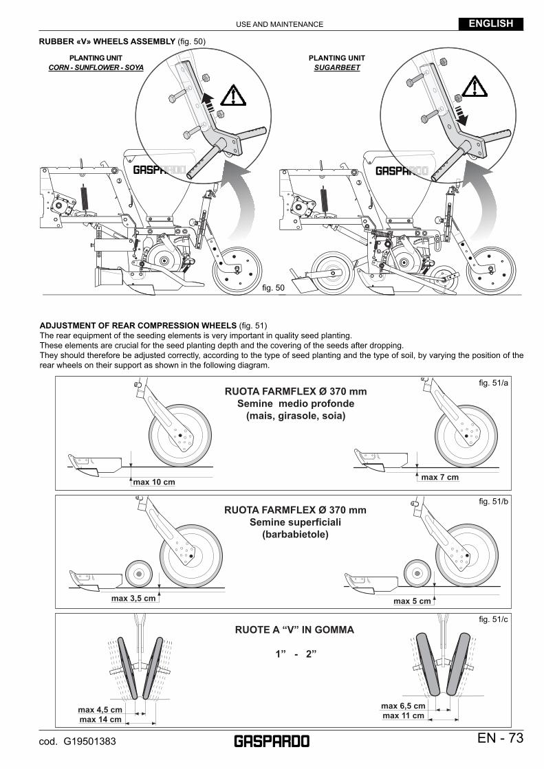
USE AND MAINTENANCE ENGLISH
EN - 73cod. G19501383
RUBBER «V» WHEELS ASSEMBLY (fi g. 50)
ADJUSTMENT OF REAR COMPRESSION WHEELS (fi g. 51)The rear equipment of the seeding elements is very important in quality seed planting.These elements are crucial for the seed planting depth and the covering of the seeds after dropping.They should therefore be adjusted correctly, according to the type of seed planting and the type of soil, by varying the position of the rear wheels on their support as shown in the following diagram.
max 10 cm max 7 cm
max 3,5 cm max 5 cm
max 14 cmmax 4,5 cm
max 11 cmmax 6,5 cm
PLANTING UNIT CORN - SUNFLOWER - SOYA
PLANTING UNIT SUGARBEET
fi g. 50
fi g. 51/a
fi g. 51/b
fi g. 51/c

USE AND MAINTENANCEENGLISH
74 - EN cod. G19501383
5.0 OPERATIONS FOR PUTTING THE MACHINE INTO SERVICE 4.1 WHEN THE MACHINE IS NEW- Assemble onto the equipment any parts that may have been delivered
disassembled for transport purposes (follow the instructions given in the assembly diagrams attached to these parts).
5 . 2 C H E C K S A N D P R E V E N TAT I V E MAINTENANCE- Check that the safety bolts are present on the pins: a) 3-point linkage connecting pins; b) pins for locking the row marker arms for road transport.- Check that the pipes of the hydraulic system are undamaged.- Check that all the screws are tight.- Grease the universal joint spiders.- Grease the row-marker disc pin.- Grease the pin of the seeding depth control wheels.- Check that all the suction tubes are well connected.- Check that all the drive shafts are properly engaged.- Carefully check moving parts, dri-ving parts and seed distribu-
tion.
5.3 ATTACHMENT THE TRACTOR- Connect the equipment to the third point of the tractor using the
safety devices.- Connect the cardan shaft.- Connect the hydraulic pipes to the distributors of the tractor.- Plug the visual signalling units into the socket of the tractor’s electrical
system.- Remove the safety bolts of the row marker arms and the toolbar, and
operate the hydraulic systems to check they are working correctly. If necessary, adjust the fl ow regulators where present.
- Lift the equipment off the ground and remove the support legs (A, Fig. 52).
- When travelling by road, lock the row marker arms and the toolbar in transport position with the safety bolts.
5.4 PREPARING FOR SEEDING- From the seed chart, according to the row spacing, obtain the di-
stance between one seed and the next along the row.- From the longitudinal sowing distance adjustment table, obtain the
combinations of gears on the gearbox and on the drive wheel that will produce this distance.
- Insert the right seed discs in the distributors.- If beet seed is to be distributed, use the seed ejector. In other cases,
remove the ejector.- Put a small quantity of seed in the hoppers.- From the driverís seat of the tractor, raise the seeder;- Operate the power take-off at 540 rpm;- Using the gear lever, put the tractor engine into neutral;- Brake the tractor and if necessary, secure it with wooden blocks
sized according to the size of the wheels;- Manually turn the seeder gear drive wheel in the direction in which
the machine is moving;- Adjust the selector and control through the grate that the plate is
only holding one seed per hole (Fig. 53);- Adjust the planting depth by turning the side wheels by means
of the handle.- According to the type of ground, adjust the distance of the rear
wheels and their pressure on the ground for closing the seed furrow.
- Check the degree of preparation of the seedbed and adjust the height of the front clod clearer.
- Move along the seedbed for a few metres with the equipment in working position, and adjust the third point tie rod to obtain true perpendicularity between machine and ground.
- Proceed with the planting process: after a few metres check whether the distributors are placing one seed at a time and at the right distance.
5 . 5 D I S T R I B U T I O N O F C H E M I C A L PRODUCTS- Hoppers and tanks can be fi lled by hand or using a lifter with a
capacity of at least 200 kg, which must be regularly approved by the relative authorities.
- When fi lling the fertilizer and insecticide hoppers, be careful that foreign bodies do not enter (string, bag paper, etc.).
- Set the quantity to distribute following the information given in the table (the values given in the table are a rough guide only).
- Adjust the working depth and the distance of the fertilizer place-ment units from the sowing row, carefully following the specifi c agronomic instructions of each crop.
fi g. 53fi g. 52
B
A
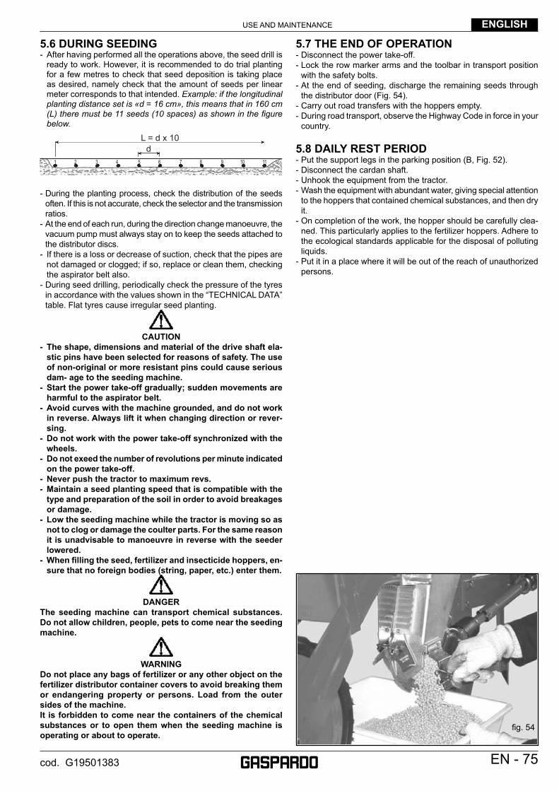
USE AND MAINTENANCE ENGLISH
EN - 75cod. G19501383
5.6 DURING SEEDING- After having performed all the operations above, the seed drill is
ready to work. However, it is recommended to do trial planting for a few metres to check that seed deposition is taking place as desired, namely check that the amount of seeds per linear meter corresponds to that intended. Example: if the longitudinal planting distance set is «d = 16 cm», this means that in 160 cm (L) there must be 11 seeds (10 spaces) as shown in the fi gure below.
dL = d x 10
1 2 3 4 5 6 7 8 9 10 11
- During the planting process, check the distribution of the seeds often. If this is not accurate, check the selector and the transmission ratios.
- At the end of each run, during the direction change manoeuvre, the vacuum pump must always stay on to keep the seeds attached to the distributor discs.
- If there is a loss or decrease of suction, check that the pipes are not damaged or clogged; if so, replace or clean them, checking the aspirator belt also.
- During seed drilling, periodically check the pressure of the tyres in accordance with the values shown in the “TECHNICAL DATA” table. Flat tyres cause irregular seed planting.
CAUTION- The shape, dimensions and material of the drive shaft ela-
stic pins have been selected for reasons of safety. The use of non-original or more resistant pins could cause serious dam- age to the seeding machine.
- Start the power take-off gradually; sudden movements are harmful to the aspirator belt.
- Avoid curves with the machine grounded, and do not work in reverse. Always lift it when changing direction or rever-sing.
- Do not work with the power take-off synchronized with the wheels.
- Do not exeed the number of revolutions per minute indicated on the power take-off.
- Never push the tractor to maximum revs. - Maintain a seed planting speed that is compatible with the
type and preparation of the soil in order to avoid breakages or damage.
- Low the seeding machine while the tractor is moving so as not to clog or damage the coulter parts. For the same reason it is unadvisable to manoeuvre in reverse with the seeder lowered.
- When fi lling the seed, fertilizer and insecticide hoppers, en-sure that no foreign bodies (string, paper, etc.) enter them.
DANGERThe seeding machine can transport chemical substances. Do not allow children, people, pets to come near the seeding machine.
WARNINGDo not place any bags of fertilizer or any other object on the fertilizer distributor container covers to avoid breaking them or endangering property or persons. Load from the outer sides of the machine.It is forbidden to come near the containers of the chemical substances or to open them when the seeding machine is operating or about to operate.
5.7 THE END OF OPERATION- Disconnect the power take-off.- Lock the row marker arms and the toolbar in transport position
with the safety bolts.- At the end of seeding, discharge the remaining seeds through
the distributor door (Fig. 54).- Carry out road transfers with the hoppers empty. - During road transport, observe the Highway Code in force in your
country.
5.8 DAILY REST PERIOD- Put the support legs in the parking position (B, Fig. 52).- Disconnect the cardan shaft.- Unhook the equipment from the tractor.- Wash the equipment with abundant water, giving special attention
to the hoppers that contained chemical substances, and then dry it.
- On completion of the work, the hopper should be carefully clea-ned. This particularly applies to the fertilizer hoppers. Adhere to the ecological standards applicable for the disposal of polluting liquids.
- Put it in a place where it will be out of the reach of unauthorized persons.
fi g. 54
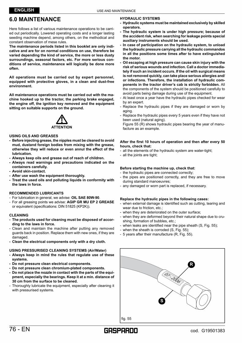
USE AND MAINTENANCEENGLISH
76 - EN cod. G19501383
6.0 MAINTENANCEHere follows a list of various maintenance operations to be carri-ed out periodically. Lowered operating costs and a longer lasting seeding machine depend, among others, on the methodical and constant observation of mese rules. The maintenance periods listed in this booklet are only indi-cative and are for on normal conditions on use, therefore be varied depending the kind of service, the more or less dusty surroundings, seasonal factors, etc. For more serious con-ditions of service, maintenance will logically be done more often.
All operations must be carried out by expert personnel, equipped with protective gloves, in a clean and dust-free environment.
All maintenance operations must be carried out with the ma-chine hooked up to the tractor, the parking brake engaged, the engine off, the ignition key removed and the equipment sitting on suitable supports on the ground.
ATTENTION
USING OILS AND GREASES- Before injecting grease, the nipples must be cleaned to avoid
mud, dustand foreign bodies from mixing with the grease, otherwise they will reduce or even annul the effect of the lubrication.
- Always keep oils and grease out of reach of children.- Always read warnings and precautions indicated on the
containers carefully.- Avoid skin-contact.- After use wash the equipment thoroughly.- Treat the used oils and polluting liquids in conformity with
the laws in force.
RECOMMENDED LUBRICANTS- For lubrication in general, we advise: OIL SAE 80W-90.- For all greasing points we advise: AGIP GR MU EP 2 GREASE
or equivalent (specifi cations: DIN 51825 (KP2K)).
CLEANING- The products used for cleaning must be disposed of accor-
ding to the laws in force.- Clean and maintain the machine after putting any removed
guards back in position. Replace them with new ones, if they are damaged.
- Clean the electrical components only with a dry cloth.
USING PRESSURISED CLEANING SYSTEMS (Air/Water) - Always keep in mind the rules that regulate use of these
systems.- Do not pressure clean electrical components.- Do not pressure clean chromium-plated components.- Do not place the nozzle in contact with the parts of the equi-
pment, especially the bearings. Keep it at a min. distance of 30 cm from the surface to be cleaned.
- Thoroughly lubricate the equipment, especially after cleaning it with pressurised systems.
HYDRAULIC SYSTEMS - Hydraulic systems must be maintained exclusively by skilled
operators.- The hydraulic system is under high pressure; because of
the accident risk, when searching for leakage points special auxiliary instruments should be used.
- In case of participation on the hydraulic system, to unload the hydraulic pressure carrying all the hydraulic commandos in all the positions some times after to have extinguished the motor.
- Oil escaping at high pressure can cause skin injury with the risk of serious wounds and infection. Call a doctor immedia-tely if such an incident occurs. If the oil with surgical means is not removed quickly, can take place serious allergies and/or infections. Therefore, the installation of hydraulic com-ponents in the tractor driver’s cab is strictly forbidden. All the components of the system should be positioned carefully to avoid parts being damage during use of the equipment.
- At least once a year have the hydraulic pipes checked for wear by an expert.
- Replace the hydraulic pipes if they are damaged or worn by aging.
- Replace the hydraulic pipes every 5 years even if they have not been used (natural aging).
Figure 55 (R) shows hydraulic pipes bearing the year of manu-facture as an example.
After the fi rst 10 hours of operation and then after every 50 hours, check that:- all the elements of the hydraulic system are water-tight;- all the joints are tight;
Before starting the machine up, check that:- the hydraulic pipes are connected correctly;- the pipes are positioned correctly, and they are free to move
during standard manoeuvres;- any damaged or worn part is replaced, if necessary.
Replace the hydraulic pipes in the following cases:- when external damage is identifi ed such as cutting, tearing and
wear due to friction, etc.;- when they are deteriorated on the outer surface;- when they are deformed beyond their natural shape due to cru-
shing, formation of bubbles, etc.;- when leaks are identifi ed near the pipe sheath (S, Fig. 55);- when the sheath is corroded (S, Fig. 55);- 5 years after their manufacture (R, Fig. 55).
fi g. 55
R
S
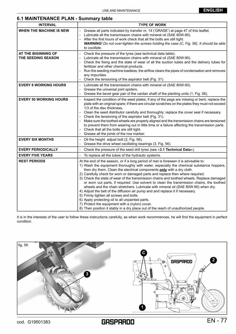
USE AND MAINTENANCE ENGLISH
EN - 77cod. G19501383
6.1 MAINTENANCE PLAN - Summary tableINTERVAL TYPE OF WORK
WHEN THE MACHINE lS NEW - Grease all parts indicated by transfer nr. 14 (‘GRASE’) at page 47 of this leafl et.- Lubricate all the transmission chains with mineral oil (SAE 80W-90).- After the fi rst hours of work check that all the bolts are still tight.
WARNING! Do not over-tighten the screws holding the case (C, Fig. 56). It should be able to oscillate.
AT THE BIGINNING OFTHE SEEDING SEASON
- Check the pressure of the tyres (see technical data table).- Lubricate all the transmission chains with mineral oil (SAE 80W-90).- Check the fi xing and the state of wear of all the suction tubes and the delivery tubes for
fertilizer and other chemical products.- Run the seeding machine loadless, the airfl ow clears the pipes of condensation and removes
any impurities.- Check the tensioning of the aspirator belt (Fig. 31).
EVERY 8 WORKING HOURS - Lubricate all the transmission chains with mineral oil (SAE 80W-90).- Grease the universal joint spiders.- Grease the bevel gear pair of the cardan shaft of the planting units (1, Fig. 56).
EVERY 50 WORKING HOURS - Inspect the condition of the seed plates; if any of the pegs are missing or bent, replace the plate with an original spare; if there are circular scratches on the plates they must not exceed 1/3 of the disc thickness.
- Clean the seed distributor carefully and thoroughly; replace the cover seal if necessary.- Check the tensioning of the aspirator belt (Fig. 31).- Make sure the toothed wheels are properly aligned and the transmission chains are tensioned
to prevent them from wearing out in little time or a failure affecting the transmission parts.- Check that all the bolts are still tight.- Grease all the joints of the row marker.
EVERY SIX MONTHS - Oil the height adjust bolt (2, Fig. 56).- Grease the drive wheel oscillating bearings (3, Fig. 56).
EVERY PERIODICALLY - Check the pressure of the seed drill tyres (see «3.1 Technical Data»).EVERY FIVE YEARS - To replace all the tubes of the hydraulic systems. REST PERIODS At the end of the season, or if a long period of rest is foreseen it is advisable to:
1) Wash the equipment thoroughly with water, especially the chemical substance hoppers, then dry them. Clean the electrical components only with a dry cloth.
2) Carefully check for worn or damaged parts and replace then where required.3) Check the state of wear of the transmission chains and toothed wheels. Replace damaged
or worn out parts, if required. Use solvent to clean the transmission chains, the toothed wheels and the chain stretchers. Lubricate with mineral oil (SAE 80W-90) when dry.
4) Adjust the belt of the diffusion air pump and and replace it if necessary.5) Firmly tighten all screws and bolts.6) Apply protecting oil to all unpainted parts.7) Protect the equipment with a (nylon) cover.8) Then position it stably in a dry place out of the reach of unauthorized people.
It is in the interests of the user to follow these instructions carefully, as when work recommences, he will fi nd the equipment in perfect condition.
3
C2
1
fi g. 56
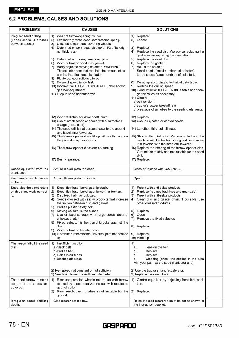
USE AND MAINTENANCEENGLISH
78 - EN cod. G19501383
6.2 PROBLEMS, CAUSES AND SOLUTIONS
PROBLEMS CAUSES SOLUTIONS
Irregular seed drilling( inaccura te d is tance between seeds).
1) Wear of furrow-opening coulter.2) Excessively tense seed compression spring.3) Unsuitable rear seed-covering wheels.4) Deformed or worn seed disc (over 1/3 of its origi-
nal thickness).
5) Deformed or missing seed disc pins.6) Worn or broken seed disc gasket.7) Badly adjusted moving selector. WARNING!
The selector does not regulate the amount of air coming into the seed distributor.
8) Flat tyres: gear ratio is altered.9) Forward speed is too fast.10) Incorrect WHEEL-GEARBOX AXLE ratio and/or
gearbox adjustment.11) Drop in seed aspirator revs.
12) Wear of distributor drive shaft joints.13) Use of small seeds or seeds with electrostatic
charge (rape, beet).14) The seed drill is not perpendicular to the ground
and is pointing forwards.15) The furrow opener discs fi ll up with earth because
they are sloping backwards.
16) The furrow opener discs are not turning.
17) Bush clearance.
1) Replace2) Loosen
3) Replace4) Replace the seed disc. We advise replacing the
gasket when replacing the seed disc.5) Replace the seed disc.6) Replace the gasket.7) Adjust the selector: Small seeds (small numbers of selector). Large seeds (large numbers of selector).
8) Pump up according to technical data table.9) Reduce the drilling speed.10) Consult the WHEEL-GEARBOX table and chan-
ge the ratios as necessary.11) Check: a) belt tension b) tractor’s power take-off revs c) breakage of air tubes to the seeding elements.
12) Replace13) Use the ejector for coated seeds.
14) Lengthen third point linkage.
15) Shorten the third point. Remember to lower the machine with the tractor moving and never move it in reverse with the seed drill lowered.
16) Replace the bearing of the furrow opener disc. Ground too muddy and not suitable for the seed drill.
17) Replace.
Seeds spill over from the distributor.
Anti-spill-over plate too open. Close or replace with G22270133.
Few seeds reach the di-stributor.
Anti-spill-over plate too closed. Open
Seed disc does not rotate or does not work correct-ly.
1) Seed distributor bevel gear is stuck.2) Seed distributor bevel gear is worn or broken.3) Disc feed hub has oxidized.4) Seeds dressed with sticky products that increase
the friction between disc and gasket.5) Broken plastic safety bolt.6) Moving selector is too closed.7) Use of fi xed selector with large seeds (beans,
chickpeas, etc).8) Fixed selector is bent and knocks against the
disc.9) Worn or broken transfer case.10) Distributor transmission universal joint not hooked
up.
1) Free it with anti-seize products.2) Replace (replace bushings and gear axle).3) Free it with anti-seize products.4) Clean disc and gasket often. If possible, use
other dressed products.
5) Replace6) Open7) Remove the fi xed selector.
8) Replace
9) Replace10) Hook up
The seeds fall off the seed disc.
1) Insuffi cient suction a) Slack belt b) Broken belt c) Holes in air tubes d) Blocked air tubes
2) Rev speed not constant or not suffi cient.3) Seed disc holes of insuffi cient diameter.
1) a. Tension the belt b. Replace c. Replace d. Cleaning (check the suction in the tube
with your palm at the seed distributor end).
2) Use the tractor’s hand accelerator.3) Replace the seed discs.
The seed furrow remains open and the seeds un-covered.
1) Rear compression wheels not in line with furrow opened by shoe; equalizer inclined with respect to gear direction.
2) Rear seed-covering wheels not suitable for the ground.
1) Centre equalizer by adjusting front fork posi-tion.
2) Replace.
Irregular seed dri l l ing depth.
Clod clearer set too low. Raise the clod clearer: it must be set as shown in the instruction booklet.

USE AND MAINTENANCE ENGLISH
EN - 79cod. G19501383
PROBLEMS CAUSES SOLUTIONS
Seeds on surface. 1) Wrong seeding depth setting.2) Obstructed shoe.3) Wear of shoe.4) Rear seed-covering wheels not suitable for the
ground.5) Insuffi cient parallel pressure.6) Ground not suitably prepared.7) Bent planting unit frame (example: caused by
knocks from stones on the ground).8) Seed drilling on steeply sloping ground.
1) Correct the depth setting.2) Clean.3) Replace.4) Replace.
5) Tighten front spring.6) Prepare the ground carefully.7) Restore the planting unit frame.
8) Regular seed drilling is not guaranteed for slopes greater than 20%.
Seeds too deep. 1) Wrong seeding depth setting.2) Excessive parallel pressure.3) Unsuitable rear seed-covering wheels.
1) Correct the depth setting.2) Loosen front spring.3) Replace
The gearbox chain jumps off the gears.
The two pinion axles are not parallel to each other. Loosen the 3 axle fi xing bolts and adjust the position of the axle support.
Irregular distribution of chemical products(Fertilizers and Microgra-nulates)
1) Wrong setting of the MINIMAX distributor and/or gear ratios.
2) Product with specifi c gravity different to those indi-cated in the table.
3) Use of non-granulated product (dusty).
4) Delivery tube bent sharply and/or blocked by depo-sits.
5) Obstructed furrower element.6) Distributor dirty with deposits.7) Protective grille fi tted the wrong way round (after
maintenance).8) Fertilizer on surface.
1) See distribution table and correct.
2) Protract the values of the table to the new specifi c gravity.
3) Dusty products are not suitable for this type of distribution. Change product.
4) Check the length, shorten them and straighten them. Cleaning.
5) Cleaning6) Cleaning7) Check the position (a gap of about 1 cm must
remain on the back).8) Increase the penetration power of the disc and
ballast the seed drill frame.
Row marker does not work or works irregularly.
1) Impurities present in the hydraulic system.
2) The row marker arms rise too quickly (damage to the structure).
1) Clean the exchange valve and the nipple with calibrated hole fi tted on the hydraulic cylinders of the row marker arms (where present).
2) Work on the fl ow regulators to correctly set the system during the upward movement of the row marker arms.
7.0 DEMOLITION AND DISPOSALThis operation is to be carried out by the customer.Before demolishing the machine, you are advised to carefully check its physical condition and ascertain whether there are any parts of the structure that may be susceptible to structural collapse or breakage during demolition. The customer should operate in compliance with the environment protection laws in force in his/her country.
CAUTIONThe machine demolition operations should be carried out by skilled personnel only, equipped with suitable protective clothing (safety footwear and gloves) and auxiliary tools and equipment. All the disassembly operations for demolition should be carried out with the machine stopped and detached from the tractor.
Before demolishing the machine, you are advised to render harmless all the parts that may be a source of danger and therefore:- scrap the structure using specialized fi rms,- remove any electrical apparatus according to the laws in force,- collect oils and greases separately, to be disposed of through specialized fi rms, in accordance with the regulations of the country in
which the machine was used.
When the machine is demolished the CE mark should be destroyed together with this manual.
Finally, we remind you that the manufacturer is always available for any and all necessary assistance and spares.

80 cod. G19501383
ESPAÑOL
ES - 157cod. G19501383
1.0 PREMISAEste Manual de instrucciones para el uso (a continuación llamado Manual) brinda al usuario informaciones útiles para trabajar correctamente y con seguridad, facilitando el uso de la SEMBRADORA.Todo lo indicado en este manual no debe ser considerado como una larga lista de advertencias, sino como una serie de instrucciones para mejorar las prestaciones de la máquina y para evitar, sobre todo, provocar daños a las personas, animales o bienes debidos a procedimientos incorrectos o a una conducción equivocada de la máquina.Es muy importante que todas las personas encargadas del transporte, instalación, puesta en servicio, uso, mantenimiento, reparación y desguace de la máquina consulten detenidamente este manual antes de proceder con las operaciones, a fi n de prevenir maniobras incorrectas e inconvenientes que podrían afectar la integridad de la máquina, o ser peligroso para la seguridad de las personas.Si después de haber leído este manual usted tuviera alguna duda sobre el uso de la máquina, contacte con el Fabricante que estará a su disposición para asegurar un servicio de asistente inmediato y profesional a fi n de mejorar el funcionamiento y la efi ciencia de la máquina.Por último, recuerde que durante todas las etapas de uso de la máquina siempre habrá que observar las normativas vigentes en materia de seguridad, higiene en el trabajo y protección del medio ambiente. Por consiguiente, el usuario deberá controlar que la máquina sea accionada únicamente en condiciones excelentes de seguridad para las personas y bienes.Este manual forma parte integrante del producto y, junto con la Declaración de Conformidad, debe guardarse en un lugar seguro para poderlo consultar durante toda la vida útil de la máquina y en el caso de reventa.Este manual ha sido redactado siguiendo las normativas vigentes en el momento de su impresión.El Fabricante se reserva el derecho de modifi car el equipo sin tener que actualizar inmediatamente este manual. En caso de controversia, el texto de referencia válido es aquel en idioma italiano.Algunas imágenes presentes en este manual muestran detalles o accesorios que podrían ser diferentes de aquellos de la máquina que usted posee. Es probable que se hayan quitado algunos componentes o protecciones para que las representaciones sean más claras.
1.1 GENERALIDADES
Convenciones tipográfi cas:Para contramarcar y reconocer los peligros, en el manual se utilizan los siguientes símbolos:
CUIDADO!PELIGRO PARA LA SALUD Y LA SEGURIDAD DE LAS
PERSONAS.
CUIDADO!PELIGRO DE DAÑOS A LA MÁQUINA O AL PRODUCTO
QUE SE ESTÁ PROCESANDO.
En el texto, al lado de cada símbolo, se indican las advertencias de seguridad, breves frases que ejemplifi can mejor el tipo de peligro. Las advertencias sirven para garantizar la seguridad del personal y evitar daños a la máquina o al producto que se está procesando. Los dibujos, fotografías y gráfi cos incorporados en este manual no están en escala y sirven para integrar las informaciones escritas y son un compendio de éstas, pero no sirven como representación detallada de la máquina. Para una visión más completa de la máquina, los dibujos, fotografías y esquemas, en la mayoría de los casos, no incluyen las protecciones ni los resguardos instalados.Por último, los anexos, dado que están formados de fotocopias de catálogos, dibujos, etc., mantienen el número de identifi cación y la numeración de la página original (en su caso); si así no fuera, no contienen ninguna numeración.
EMPLEO Y MANTENIMIENTOESPAÑOL
158 - ES cod. G19501383
Defi niciones:Las siguientes defi niciones pertenecen a los principales términos utilizados en el Manual. Se aconseja leerlas detenidamente antes de seguir leyendo el Manual.
• OPERADOR: ............................................... La, o las personas, encargadas de instalar, hacer funcionar, ajustar, mantener, limpiar, reparar y transportar una máquina.
• ZONA PELIGROSA: .................................... Cualquier zona en el interior y/o en proximidad de una máquina en la cual la presencia de una persona expuesta constituya un peligro para la seguridad y la salud de dicha persona.
• SITUACIÓN PELIGROSA: .......................... Cualquier situación en que un Operador está expuesto a uno o varios peligros.• RIESGO: ...................................................... Combinación de probabilidades y de gravedades de posibles lesiones o daños a la salud
en una situación peligrosa.• PROTECCIONES: ....................................... Medidas de seguridad que consisten en utilizar los equipos técnicos específi cos
(Resguardos y Dispositivos de seguridad) para proteger los Operadores de los peligros.
• RESGUARDO: ............................................. Elemento de una máquina utilizado de manera específi ca para proteger mediante una barrera física; en función de su construcción, puede ser llamado envoltura, cubierta, pantalla, puerta, cercado, cárter, segregación, etc.
• PERSONA EXPUESTA: .............................. Toda persona que se encuentre total o parcialmente en una zona peligrosa.• USUARIO: .................................................... El usuario es la persona, institución o sociedad, que compró o alquiló la máquina para
emplearla para los usos propios de la misma.• PERSONAL CUALIFICADO: ...................... Como tales se consideran las personas expresamente instruidas y habilitadas para
efectuar intervenciones de mantenimiento, o reparaciones, que requieran un conocimiento particular de la máquina, su funcionamiento, dispositivos de seguridad, modo de intervención, y que son capaces de reconocer los peligros resultantes del empleo de la máquina y, por lo tanto, pueden evitarlos.
• PERSONAL PREPARADO: ........................ Personas que han sido informadas y preparadas para poder realizar sus tareas y para los peligros respectivos.
• CENTRO DE ASISTENCIA AUTORIZADO: El centro de asistencia autorizado es la estructura legalmente autorizada por el fabricante, que dispone de personal especializado y habilitado para efectuar todas las operaciones de asistencia, mantenimiento y reparación, incluso de una cierta complejidad, que se hacen necesarias para el mantenimiento de la máquina en perfectas condiciones
Responsabilidad:El Fabricante no se asume ninguna responsabilidad directa ni indirecta en caso de: - uso inadecuado de la máquina para las actividades no previstas;- uso de la máquina por parte de un operador no autorizado, ni preparado y sin carné de conducir;- graves carencias en el mantenimiento programado;- modifi caciones o intervenciones no autorizadas;- uso de piezas de repuesto no originales ni específi cos;- inobservancia total o parcial de las instrucciones mencionadas en el manual;- inobservancia de las normas de seguridad mencionadas en el manual;- inobservancia de las disposiciones en materia de seguridad, higiene y salud en el lugar de trabajo.- eventos excepcionales no previstos.
CUIDADO• No se admite el uso por parte de menores, analfabetos o personas en condiciones físicas o psíquicas alteradas.• No se admite el uso por parte de personal sin carné de conducir adecuado o insufi cientemente informado y capacitado.• El operador es responsable de controlar el funcionamiento de la máquina, así como de sustituir y reparar las piezas sujetas a desgaste
que podrían provocar daños.• El cliente deberá informar al personal sobre los riesgos de accidente, sobre los dispositivos de seguridad, sobre los riesgos de
emisión de ruido y sobre las normas generales de seguridad previstas por las directivas internacionales y del país de destino de las máquinas.
• De todas maneras, la máquina tiene que ser utilizada sólo por personal cualifi cado que deberá respetar escrupulosamente las instrucciones técnicas y de seguridad contenidas en este manual.
• La responsabilidad de la identifi cación y de la elección de la categoría de los EPI (Equipos de Protección Individual) apropiados es del Cliente.
• La máquina tiene aplicados pictogramas que el operador deberá mantener en perfectas condiciones y que deberá sustituir cuando no sean más legíbles, tal como indicado en la normativas comunitarias.
• El usuario debe controlar que la máquina sea accionada sólo en condiciones ideales de seguridad para las personas, animales o cosas.
• El Fabricante no se asume ninguna responsabilidad por daños a cosas, o lesiones a los operadores, o a terceros provocados por cualquier modifi cación arbitraria realizada a esta máquina.
La Fabricante declina toda responsabilidad por los posibles errores contenidos en el manual si éstos fueran imputables a errores de impresión, traducción o transcripción. Las integraciones al manual de las instrucciones para el uso que el Fabricante considerará oportuno enviar al Cliente, deberán conservarse junto con el manual al cual forman parte integrante.

EMPLEO Y MANTENIMIENTO ESPAÑOL
ES - 159cod. G19501383
Síntesis de los elementos de protección individual (EPI) que se deben utilizar durante todas las operaciones con la máquina
En la Tabla 1 se indican los EPI (Elementos de Protección Individual) a utilizar durante todas las operaciones con la máquina (para cada fase existe la obligación de utilizar y/o tener a disposición los EPI).
La responsabilidad y la elección del tipo y categoría de los EPI adecuados es del Cliente.
Fase
Indumentos de protección
Calzados deseguridad Guantes Gafas Protecciones
Auriculares Mascarilla Casco
Transporte
Desplazamiento
Desembalaje
Montaje
Uso ordinario
Regulaciones
Limpieza
Mantenimiento
Desmontaje
Desguace
EPI previsto. EPI a disposición o a utilizar en su caso. EPI no previsto.
Los EPI utilizados deberán estar marcados CE y responder a la Directiva 89/686/CEE.
Las descripciones de las fases de vida de la máquina (fi gura 30) están mencionadas en la siguiente tabla.
• Transporte:..............Consiste en transportar la máquina desde una localidad a otra utilizando un medio de transporte.• Desplazamiento ......Es el transporte de la máquina desde y hacia el medio utilizado para el transporte, y los desplazamientos en el
interior del establecimiento.• Desembalaje ..........Consiste en la eliminación de todos los materiales utilizados para el embalaje de la máquina.• Montaje ...................Son todas las operaciones de montaje que preparan inicialmente la máquina para la puesta a punto.• Uso ordinario .........Uso para el cual la máquina está destinada según su diseño, fabricación y funcionamiento.• Regulaciones .........Son la regulación, puesta a punto y calibrado de todos los dispositivos que deben ser adaptados a la condición
de funcionamiento previsto normalmente.• Limpieza ..................Consiste en eliminar el polvo, aceite y residuos de trabajo que podrían comprometer el funcionamiento y el uso
correctos de la máquina, además de la salud/seguridad del operador.• Mantenimiento .......Consiste en el control periódico de las piezas de la máquina que se podrían desgastar o que se deben
sustituir.• Desmontaje .............Consiste en el desmontaje completo o parcial de la máquina para cualquier tipo de necesidad.• Desguace ................Consiste en la eliminación defi nitiva de todas las partes de la máquina obtenidas del desmantelamiento defi nitivo,
a fi n de poder realizar el reciclaje o la recogida selectiva de los componentes, según las modalidades previstas por las normas vigentes.
CUIDADOEstá prohibido utilizar guantes de protección que puedan engancharse en las piezas móviles de la máquina.
Tabla 1

EMPLEO Y MANTENIMIENTOESPAÑOL
160 - ES cod. G19501383
1.2 GARANTÍA
La garantía tiene validez por un año contra cualquier defecto de los materiales, contado a partir de la fecha de entrega del equipo.Verifi car durante la entrega que el equipo no haya sufrido daños en el transporte, que todos los accesorios estén íntegros y que no falte ninguno de ellos.EVENTUALES RECLAMOS SE DEBERÁN PRESENTAR POR ESCRITO DENTRO DE LOS 8 DÍAS A PARTIR DE LA RECEPCIÓN EN EL CONCESIONARIO.El comprador podrá hacer valer sus derechos sobre la garantía sólo si habrá respetado las condiciones concernientes la prestación de la garantía mencionadas en el contrato de provisión.
1.2.1 VENCIMIENTO DE LA GARANTÍAAparte de lo mencionado en el contrato de provisión, la garantía decae:- Si se sobrepasaran los límites anotados en la tabla de los datos técnicos.- Si no se hubieran respetado cuidadosamente las instrucciones descritas en este opúsculo.- En caso de uso erróneo, mantenimiento defectuoso y en caso de otros errores cometidos por el cliente.- Si se hicieran modifi caciones sin la autorización escrita del fabricante y si se hubiesen utilizado repuestos no originales.
1.3 IDENTIFICACIÓN
Cada equipo está provisto de una tarjeta de identifi cación (Fig.1), en la que se encuentran:
1) Marca y dirección del Fabricante.2) Tipo de la máquina.3) Peso seco, en kilogramos.4) Peso a piena carga, en kilogramos.5) Matrícula de la máquina.6) Año de fabricación.7) Marca del CE.
Se recomienda anotar los propios datos en la fi cha que bajo se muestra con la fecha de compra (8) y el nombre del concesionario (9).
8) ____________________
9) ____________________
Estos datos tendrán que mencionarse para cualquier necesidad de asistencia o repuestos.
CUIDADO
No quite, altere ni arruine la marca “CE” de la máquina.
Consulte los datos indicados en la marca “CE” de la máquina para cuando deba contactar con el Fabricante (por
ejemplo: para solicitar piezas de repuesto, etc.).
En el momento del desguace de la máquina habrá que destruir la marca “CE”.
fi g. 1
(1)
(2)
(3)
(5)
(7)
(4)
(6)

EMPLEO Y MANTENIMIENTO ESPAÑOL
ES - 161cod. G19501383
2.0 INDICACIONES GENERALES DE SEGURIDAD2.1 SEÑALES DE SEGURIDAD Y DE INDICACIÓNLas señales descritas están colocadas en la máquina (Fig. 2). Mantenerlas limpias y reemplazarlas si se desprenden o se vuelven ilegibles. Leer minuciosamente lo descrito y memorizar su signifi cado.
2.1.1 SEÑALES DE ADVERTENCIA1) Antes de comenzar a operar, leer cuidadosamente el manual
de instrucciones.2) Antes de ejecutar cualquier operación mantenimiento, parar la
máquina y consultar el manual de instrucciones.
2.1.2 SEÑALES DE PELIGRO3) Peligro de respiración de sustancias nocivas. Utilizar máscara
antipolvo en caso de empleo del tractor sin cabina o sin fi ltros.4) Peligro de aplastamiento en fase de apertura. Mantenerse a
la distancia de seguridad de la máquina.5) Peligro de quedar enganchados con el árbol cardán. Perma-
necer lejos de los órganos en movimiento.
6) Peligro de captura, permanecer lejos de los órganos en mo-vimiento.
7) Peligro de aplastamiento en fase de cierre. Permanecer a la distancia de seguridad de la máquina.
8) Utilizando productos anticripto-gámicos, equiparse con las protecciones adecuadas.
9) Nivel sonoro elevado. Equiparse con las protecciones acústi-cas adecuadas.
10) Tubos con líquidos a alta presión. En caso de rotura de tubos fl exibles prestar atención a los chorros de aceite. Leer el ma-nual de instrucciones.
11) Antes de inserir la toma de fuerza, controlar el número de revoluciones prestablecido. No confundirse entre el régimen de 540 rpm y el de 1000 rpm.
2.1.3 SEÑALES DE IDENTICACION12) Llevar ropa de trabajo adecuada contra accidentes.13) Señalización de los puntos de enganche para elevación.14) Punto de engrase.
El Fabricante no se asume ninguna responsabilidad si los pictogramas de seguridad entregados junto con la máquina no estuvieran montados, fueran ilegibles o no estuvieran aplicados.
fi g. 2Cod. G89900500DECALCOMANIE AVVERTIMENTOWARNING STICKERSABZIEHBILDER MIT WARNHINWEISENDECALCOMANIECALCOMANIAS
413
2
14
5 1011 1
4
7
7 9 88 6
14
123
EMPLEO Y MANTENIMIENTOESPAÑOL
162 - ES cod. G19501383
2.2 NORMAS DE SEGURIDAD Y PREVENCIÓN CONTRA LOS ACCIDENTES
Tener cuidado a las señales de peligro que se indican en este opúsculo.
Las señales de peligro son de tres niveles:
• PELIGRO: Esta señal advierte que si las operaciones descritas no se ejecutan de manera correcta causan graves lesiones, muerte o riesgos a largo plazo para la salud.
• CUIDADO: Esta señal advierte que si las operaciones descri-tas no se ejecutan de manera correcta pueden causar graves lesiones, muerte o riesgos a largo plazo para la salud.
• CAUTELA: Esta señal advierte que si las operaciones descritas no se ejecutan de manera correcta pueden causar daños a la máquina.
Para completar la descripción de los diversos niveles de peligro, a continuación se describen situaciones y defi niciones especí-fi cas que pueden involucrar directamente a la máquina o las personas.
• ZONA PELIGROSA: Cualquier zona en el interior y/o en proxi-midad de una máquina en la cual la presencia de una persona expuesta constituya un peligro para la seguridad y la salud de dicha persona.
• PERSONA EXPUESTA: Toda persona que se encuentre total o parcialmente en una zona peligrosa.
• OPERADOR: La, o las personas, encargadas de instalar, hacer funcionar, ajustar, mantener, limpiar, reparar y transportar una máquina.
• USUARIO: El usuario es la persona, institución o sociedad, que compró o alquiló la máquina para emplearla para los usos propios de la misma.
• PERSONAL ESPECIALIZADO: Como tales se consideran las personas expresamente instruidas y habilitadas para efectuar intervenciones de mantenimiento, o reparaciones, que requieran un conocimiento particular de la máquina, su funcionamiento, dispositivos de seguridad, modo de intervención, y que son capaces de reconocer los peligros resultantes del empleo de la máquina y, por lo tanto, pueden evitarlos.
• CENTRO DE ASISTENCIA AUTORIZADO: El centro de asi-stencia autorizado es la estructura legalmente autorizada por el fabricante, que dispone de personal especializado y habilitado para efectuar todas las operaciones de asistencia, mantenimiento y reparación, incluso de una cierta complejidad, que se hacen necesarias para el mantenimiento de la máquina en perfectas condiciones.
Leer con sumo cuidado todas las instrucciones antes de utili-zar la máquina, en caso de dudas dirigirse directamente a los técnicos de los Concesionarios de la Casa Fabricante. La Casa Fabricante se exime de cualquier responsabilidad debida a la no vigilancia de las normas de seguridad y prevención contra los accidentes que se describen a continuació:
Normas generales1) Poner atención a los símbolos de peligro indicados en este
manual y en la sembradora.2) Las etiquetas con las instrucciones, aplicadas a la máquina,
proporcionan, en forma concisa, los consejos adecuados para evitar los accidentes.
3) Respetar escrupulosamente, siguiendo todas las instrucciones indicadas, las disposiciones de seguridad y prevención contra accidentes.
4) Evitar absolutamente tocar las partes en movimiento.5) Cualquier intervención o regulación sobre el equipo tendrán
que efectuarse siempre con el motor apagado y el tractor bloqueado.
6) Se prohibe absolutamente el transporte de personas o animales en el equipo.
7) Es absolutamente prohibido conducir o hacer conducir el tractor, con el equipo aplicado, por personal que no tenga licencia de conducir, que sea inexperto o que no se encuentre en buenas condiciones de salud.
8) Antes de poner en marcha el tractor y el equipo mismo, controlar la perfecta integridad de todos los dispositivos de seguridad para el transporte y el uso.
9) Antes de poner en marcha el equipo, verifi car que alrededor de la máquina no se encuentren personas, sobre todo niños, o animales domésticos. Cerciorarse también que la visibilidad sea óptima.
10) Utilizar indumentos que sean apropiados al tipo de trabajo. Evitar absolutamente los indumentos holgados o con partes que de alguna manera puedan engancharse en partes giratorias o en órganos en movimiento.
11) Antes de comenzar a trabajar, habrá que aprender a conocer y a utilizar los dispositivos de mando y sus respectivas funcio-nes.
12) Comenzar a trabajar con el equipo únicamente si todos los dispositivos de protección están intactos, instalados y en po-sición de seguridad.
13) Es absolutamente prohibido aparcarse en el área de acción de la máquina, en donde se encuentren partes en movimiento.
14) Es absolutamente prohibido el uso del equipo desprovisto de las protecciones y de las tapas de los contenedores.
15) Antes de dejar el tractor, bajar el equipo enganchado al grupo elevador, parar el motor, activar el freno de mano y sacar la llave de encendido del tablero de mandos, cerciorarse de que nadie pueda acercarse a las substancias químicas.
16) No abandonar nunca el puesto de conducción mientras el tractor se encuentra en marcha.
17) Antes de poner en marcha el equipo, controlar que las patas de soporte, que se encuentran debajo de la sembradora, hayan sido sacadas; controlar que la sembradora haya sido montada y ajustada de manera correcta; controlar que la máquina esté perfectamente funcionante y que todos los órganos sujetos a desgaste o deterioro funcionen correctamente.
18) Antes de desganchar los aparejos de la conexión del tercer punto, colocar la palanca de mando del elevador en la posición de bloqueo y bajar los pies de apoyo.
19) Trabajara siempre en condiciones de buena visibilidad.20) Todas las operaciones tienen que ser efectuadas por personal
experto, provisto de guantes protectores, en ambiente limpio y sin polvo.

EMPLEO Y MANTENIMIENTO ESPAÑOL
ES - 163cod. G19501383
Conexión al tractor1) Enganchar el equipo, como previsto, a un tractor cuya potencia
y confi guración sean las adecuadas, utilizando el respectivo dispositivo (elevador) conforme a las normas.
2) La categoría de los pernos de enganche del equipo tiene que corresponder a la del gancho del elevador.
3) Tener mucho cuidado cuando se trabaja en la zona de los bra-zos de levantamiento, puesto que es un área muy peligrosa.
4) Tener mucho cuidado durante la fase de enganche y desen-ganche del equipo.
5) Es absolutamente prohibido colocarse entre el tractor y el gancho para mover el mando de elevación, desde el exterior. (Fig. 3).
6) Es absolutamente prohibido colocarse entre el tractor y el equipo (Fig. 3) mientras el motor esté encendido, el cardán insertado. Es posible interponerse solo después de haber accionado el freno de estacionamiento y haber introducido, debajo de las ruedas, un cepo o una piedra que bloquee ade-cuadamente.
7) La aplicación al tractor de un equipo adicional, comporta una distribución diferente de los pesos sobre los ejes; por consi-guiente, se aconseja añadir contrapesos en la parte delantera del tractor, de manera que se equilibren los pesos sobre los ejes. Verifi car la compatibilidad de las prestaciones del tractor con el peso que la sembradora transfi ere al gancho de tres puntos. En caso de dudas, consultar el fabricante del tractor.
8) Respetar el peso máximo previsto sobre el eje, el peso total móvil, la reglamentación para el transporte y el código de cir-culación.
Circulación por carretera1) Para la circulación por carretera, será necesario atenerse a
las normas del código de circulación en vigor en el país corre-spondiente.
2) Los eventuales accesorios para el transporte tienen que estar provistos de señalizaciones y protecciones adecuadas.
3) Es muy importante tener en cuenta que la estabilidad de ruta y la capacidad de dirección y frenado pueden sufrir modifi cacio-nes, enormes, debido a la presencia de un equipo que viene transportado o remolcado.
4) En las curvas, tener mucho cuidado con: la fuerza centrífuga ejercitada en una posición distinta, del centro de gravedad, con y sin herramienta portante, mayor atención también en carreteras o terrenos con pendencias.
5) Para la fase de transporte, regular y sujetar las cadenas de los brazos laterales de levantamiento del tractor; controlar que las tapas de los depósitos de las semillas y del abono se encuen-tren bien cerradas; colocar la palanca del mando del elevador hidráulico en la posición de bloqueo; Enganchar los elementos di siembra siguiendo las indicaciones di pag 179.
6) Durante los desplazamientos por carreteras todos los tanques deben encontrarse vacíos.
7) Los desplazamientos fuera de la zona de trabajo tienen que efectuarse con el equipo en posición de transporte.
8) La Empresa Fabricante suministra, sobre pedido, soportes y tarjetas para señalar el espacio de obstrucción.
9) Si las dimensiones de los aparatos cargados o semi- cargados no permiten la visibilidad de los dispositivos de indicación e ilu-minación de la motriz, dichos dispositivos deberán ser instalados adecuadamente sobre los aparatos en sí, ateniéndose a las normas del código del transito vigente en el País. Asegurarse, mientras viene utilizado, que la instalación de las luces se en-cuentre perfectamente en función.
Árbol Cardán1) El equipo aplicado, puede ser controlado sólo a través del árbol
cardán completo con los diversos dispositivos de seguridad necesarios para los caso de sobrecargas y de las protecciones fi jadas con la correspondiente cadenilla.
2) Utilizar exclusivamente el árbol cardán previsto por el Fabri-cante.
3) La instalación y el desmontaje del árbol cardán tiene que efectuarse siempre con el motor apagado.
4) Tener mucho cuidado que tanto el montaje como la seguridad del árbol cardán sea efectuado correctamente.
5) Bloquear la rotación de la protección del árbol cardán con la cadenilla en dotación.
6) Tener mucho cuidado con la protección del árbol cardán, tanto en durante la posición de transporte como en la de trabajo.
7) Controlar a menudo y periódicamente la protección del árbol cardán, que debe encontrarse siempre en óptimas condicio-nes.
8) Antes de insertar la toma de fuerza, cerciorarse que la cantidad de revoluciones establecidas sea el indicado en la calcomanía colocada sobre el aparato.
9) Antes de insertar la toma de fuerza, cerciorarse que no hayan personas o animales en la zona de acción y que el régimen seleccionado corresponda al permitido. No sobrepasar nunca el valor máximo previsto.
10) Tener cuidado con el cardán en rotación.11) No activar la toma de fuerza mientras el motor está apagado
o en sincronismo con las ruedas.12) Desactivar, siempre, la toma de fuerza cuando el árbol cardán
realiza un ángulo demasiado abierto (nunca por encima de los 10 grados - Fig. 4) y cuando no se utiliza.
13) Limpiar y engrasar el árbol cardán sólo cuando la toma de fuerza está desactivada, el motor apagado, el freno de mano activado y la llave desconectada.
14) Cuando no es necesario, apoyar el árbol cardán sobre el so-porte previsto para ser utilizado en dicha operación.
15) Después del desmontaje del árbol cardán, reponer el casquillo protector en el eje de la toma de fuerza.
fi g. 4fi g. 3
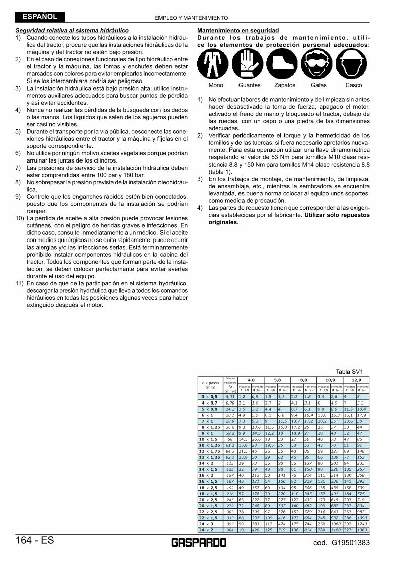
EMPLEO Y MANTENIMIENTOESPAÑOL
164 - ES cod. G19501383
Seguridad relativa al sistema hidráulico1) Cuando conecte los tubos hidráulicos a la instalación hidráu-
lica del tractor, procure que las instalaciones hidráulicas de la máquina y del tractor no estén bajo presión.
2) En el caso de conexiones funcionales de tipo hidráulico entre el tractor y la máquina, las tomas y enchufes deben estar marcados con colores para evitar emplearlos incorrectamente. Si se los intercambiara podría ser peligroso.
3) La instalación hidráulica está bajo presión alta; utilice instru-mentos auxiliares adecuados para buscar puntos de pérdida y así evitar accidentes.
4) Nunca no realizar las pérdidas de la búsqueda con los dedos o las manos. Los líquidos que salen de los agujeros pueden ser casi no visibles.
5) Durante el transporte por la vía pública, desconecte las cone-xiones hidráulicas entre el tractor y la máquina y fíjelas en el soporte correspondiente.
6) No utilice por ningún motivo aceites vegetales porque podrían arruinar las juntas de los cilindros.
7) Las presiones de servicio de la instalación hidráulica deben estar comprendidas entre 100 bar y 180 bar.
8) No sobrepasar la presión prevista de la instalación oleohidráu-lica.
9) Controle que los enganches rápidos estén bien conectados, puesto que los componentes de la instalación se podrían romper.
10) La pérdida de aceite a alta presión puede provocar lesiones cutáneas, con el peligro de heridas graves e infecciones. En dicho caso, consulte inmediatamente a un médico. Si el aceite con medios quirúrgicos no se quita rápidamente, puede ocurrir las alergias y/o las infecciones serias. Está terminantemente prohibido instalar componentes hidráulicos en la cabina del tractor. Todos los componentes que forman parte de la insta-lación, se deben colocar perfectamente para evitar averías durante el uso del equipo.
11) En caso de que de la participación en el sistema hydráulico, descargar la presión hydráulica que lleva a todos los comandos hidráulicos en todas las posiciones algunas veces para haber extinguido después el motor.
Mantenimiento en seguridadDuran te los t raba jos de manten imien to , u t i l i -ce los elementos de protección personal adecuados:
Mono Guantes Zapatos Gafas Casco
1) No efectuar labores de mantenimiento y de limpieza sin antes haber desasctivado la toma de fuerza, apagado el motor, activado el freno de mano y bloqueado el tractor, debajo de las ruedas, con un cepo o una piedra de las dimensiones adecuadas.
2) Verifi car periódicamente el torque y la hermeticidad de los tornillos y de las tuercas, si fuera necesario apretarlos nueva-mente. Para esta operación utilizar una llave dinamométrica respetando el valor de 53 Nm para tornillos M10 clase resi-stencia 8.8 y 150 Nm para tornillos M14 clase resistencia 8.8 (tabla 1).
3) En los trabajos de montaje, de mantenimiento, de limpieza, de ensamblaje, etc., mientras la sembradora se encuentra levantada, es buena norma colocar al equipo unos soportes, como medida de precaución.
4) Las partes de repuesto tienen que corresponder a las exigen-cias establecidas por el fabricante. Utilizar sólo repuestos originales.
Tabla SV1
EMPLEO Y MANTENIMIENTO ESPAÑOL
ES - 165cod. G19501383
3.0 DESCRIPCIÓN DE LA SEMBRADORAEste equipo agrícola, que se denomina «Sembradora Neumática», puede operar sólo mediante árbol cardán aplicado a la toma de fuerza de un tractor agrícola provisto de grupo elevador con gancho universal en los tres puntos. El equipo es particularmente idóneo para siembras de precisión, para usos polivalentes y con cualquier tipo de semilla en terrenos labrados. El funcionamiento de la sembradora es neumático y puede equiparse con distintos accesorios, por ejemplo la abonadora, la microgranuladora y elementos de siembra adicionales. El concepto básico de “modularidad” se ha desarrollado y asociado al de «sencillez», tanto desde el punto de vista constructivo como del de facilidad de manejo.
CUIDADOL’equipo es idóneo sólo para el empleo arriba indicado. La velocidad de trabajo recomendada es de 6÷8 km/h. El transporte del equipo por carretera debe ser efectuado con los depósitos y tolvas vacíos y a una velocidad máxima de 25 km/h. Cualquier otro uso diferente al descrito en estas instrucciones, puede causar daños a la maquina y constituir un serio peligro para el utilizador.La máquina está destinada para un uso profesional y debe ser utilizada exclusivamente por personal preparado, autorizado y que posea el carné de conducción necesario.
Modo de empleo• La máquina ha sido construida para dosifi car y esparcir las calidades de semillas (abono) normalmente disponibles en el comercio.• La máquina está destinada a usuarios profesionales y sólo puede ser utilizada por operadores especializados.• La máquina debe ser maniobrada por un operador solo.• La máquina no puede ser utilizada en otros sectores que no sea el sector agrícola.
El uso conforme también está constituido por:• el respeto de todas las indicaciones presentes en este manual;• la ejecución de las operaciones de inspección y mantenimiento descritas en este manual;• el uso exclusivo de repuestos originales GASPARDO.
El Cliente debe asegurarse de que el Personal Cualifi cado para el uso ordinario de la máquina esté bien preparado y demuestre competencia en realizar sus tareas, cuidando su seguridad y la de las demás personas.Según el tipo de tarea que se ha de llevar a cabo, los operadores cualifi cados deberán conocer perfectamente las funciones de la máquina para poderla utilizar correctamente y de manera efi ciente. Del uso correcto y el mantenimiento adecuado depende el funcionamiento regular del equipo; por consiguiente, se aconseja respetar escrupulosamente lo descrito al objeto de prevenir cualquier inconveniente que podría perjudicar el buen funcionamiento y su duración. Asimismo, es importante ajustarse a lo explicado en el presente opúsculo, ya que la Casa Fabricante se exime de cualquier responsabilidad debida al descuido y a la inobservancia de las normas mencionadas. De todas formas, la Casa Fabricante está a completa disposición para asegurar una inmediata y esmerada asistencia técnica, así como también todo lo que podrá precisarse para mejorar el funcionamiento y obtener el máximo rendimiento del equipo. En caso de daños que deriven de un uso disconforme, la responsabilidad será exclusivamente del usuario.
CUIDADO!La máquina debe ser utilizada exclusivamente por personal cualifi cado del Cliente. El operador deberá utilizar los equipos de protección individual (zapatos de seguridad, monos y guantes de trabajo, etc.).
Precauciones de empleoA continuación se mencionan las precauciones principales de empleo del equipo:• asegúrese de que en el terreno que se ha de trabajar no haya piedras;• asegúrese de que en el terreno que se ha trabajar no haya elementos metálicos, en particular, redes, cables, alambres, cadenas, tubos,
etc;
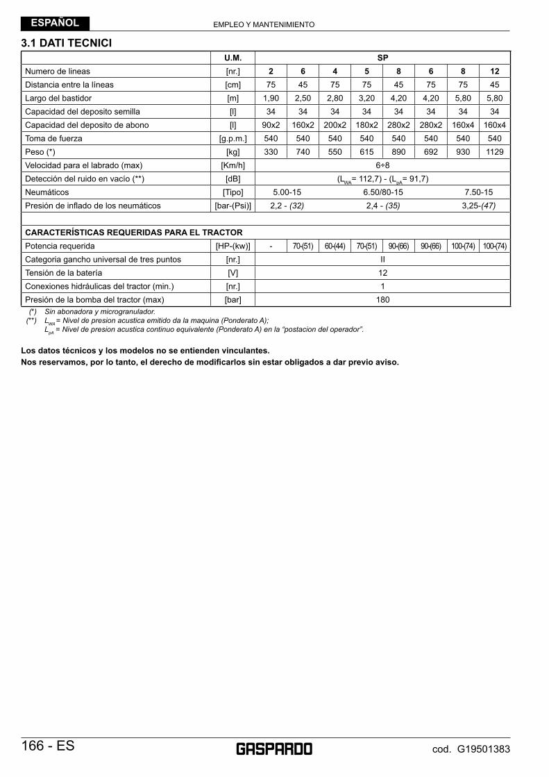
EMPLEO Y MANTENIMIENTOESPAÑOL
166 - ES cod. G19501383
3.1 DATI TECNICIU.M. SP
Numero de lineas [nr.] 2 6 4 5 8 6 8 12Distancia entre la l íneas [cm] 75 45 75 75 45 75 75 45Largo del bastidor [m] 1,90 2,50 2,80 3,20 4,20 4,20 5,80 5,80Capacidad del deposito semilla [l] 34 34 34 34 34 34 34 34Capacidad del deposito de abono [l] 90x2 160x2 200x2 180x2 280x2 280x2 160x4 160x4Toma de fuerza [g.p.m.] 540 540 540 540 540 540 540 540Peso (*) [kg] 330 740 550 615 890 692 930 1129Velocidad para el labrado (max) [Km/h] 6÷8Detecci ón del ruido en vací o (**) [dB] (LWA= 112,7) - (LpA= 91,7)Neumáticos [Tipo] 5.00-15 6.50/80-15 7.50-15Presión de infl ado de los neumáticos [bar-(Psi)] 2,2 - (32) 2,4 - (35) 3,25-(47)
CARACTERÍSTICAS REQUERIDAS PARA EL TRACTORPotencia requerida [HP-(kw)] - 70-(51) 60-(44) 70-(51) 90-(66) 90-(66) 100-(74) 100-(74)Categoria gancho universal de tres puntos [nr.] IITensión de la batería [V] 12Conexiones hidráulicas del tractor (min.) [nr.] 1Presión de la bomba del tractor (max) [bar] 180
(*) Sin abonadora y microgranulador. (**) LWA = Nivel de presion acustica emitido da la maquina (Ponderato A); LpA = Nivel de presion acustica continuo equivalente (Ponderato A) en la “postacion del operador”.
Los datos técnicos y los modelos no se entienden vinculantes.Nos reservamos, por lo tanto, el derecho de modifi carlos sin estar obligados a dar previo aviso.
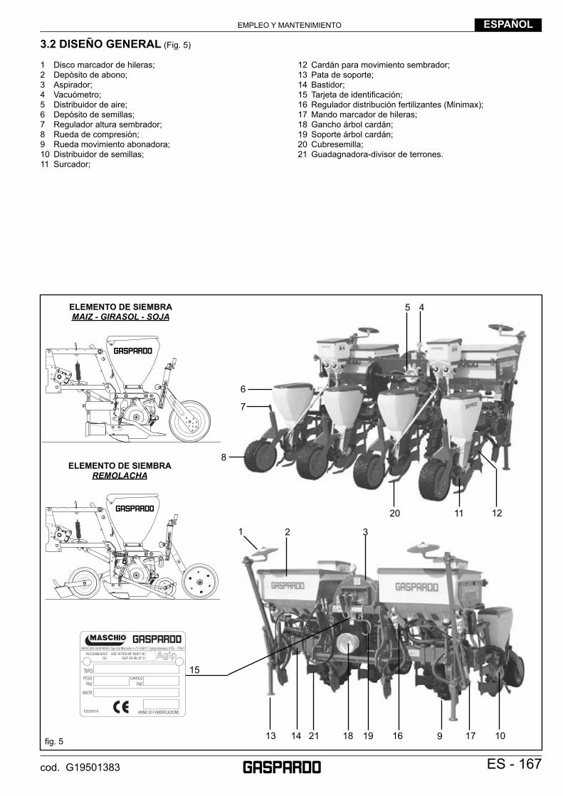
EMPLEO Y MANTENIMIENTO ESPAÑOL
ES - 167cod. G19501383
3.2 DISEÑO GENERAL (Fig. 5)
1 Disco marcador de hileras;2 Depósito de abono;3 Aspirador;4 Vacuómetro;5 Distribuidor de aire;6 Depósito de semillas;7 Regulador altura sembrador;8 Rueda de compresión;9 Rueda movimiento abonadora;10 Distribuidor de semillas;11 Surcador;
12 Cardán para movimiento sembrador;13 Pata de soporte;14 Bastidor;15 Tarjeta de identifi cación;16 Regulador distribución fertilizantes (Minimax);17 Mando marcador de hileras;18 Gancho árbol cardán;19 Soporte árbol cardán;20 Cubresemilla;21 Guadagnadora-divisor de terrones.
fi g. 5
15
16 1718 19
20
ELEMENTO DE SIEMBRA MAIZ - GIRASOL - SOJA
21
ELEMENTO DE SIEMBRA REMOLACHA
913 14
1 2 3
10
6
7
8
45
11 12
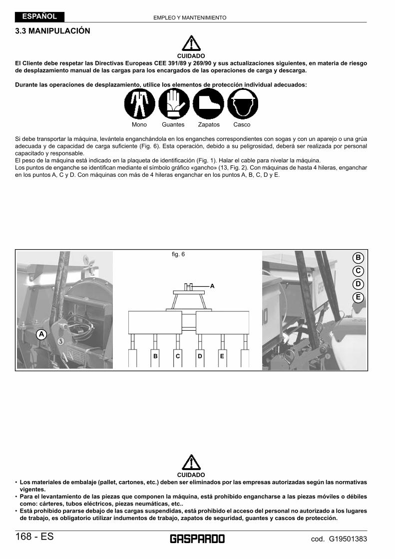
EMPLEO Y MANTENIMIENTOESPAÑOL
168 - ES cod. G19501383
3.3 MANIPULACIÓN
CUIDADO
El Cliente debe respetar las Directivas Europeas CEE 391/89 y 269/90 y sus actualizaciones siguientes, en materia de riesgo de desplazamiento manual de las cargas para los encargados de las operaciones de carga y descarga.
Durante las operaciones de desplazamiento, utilice los elementos de protección individual adecuados:
Mono Guantes Zapatos Casco
Si debe transportar la máquina, levántela enganchándola en los enganches correspondientes con sogas y con un aparejo o una grúa adecuada y de capacidad de carga sufi ciente (Fig. 6). Esta operación, debido a su peligrosidad, deberá ser realizada por personal capacitado y responsable. El peso de la máquina está indicado en la plaqueta de identifi cación (Fig. 1). Halar el cable para nivelar la máquina.Los puntos de enganche se identifi can mediante el símbolo gráfi co «gancho» (13, Fig. 2). Con máquinas de hasta 4 hileras, enganchar en los puntos A, C y D. Con máquinas con más de 4 hileras enganchar en los puntos A, B, C, D y E.
CUIDADO
• Los materiales de embalaje (pallet, cartones, etc.) deben ser eliminados por las empresas autorizadas según las normativas vigentes.
• Para el levantamiento de las piezas que componen la máquina, está prohibido engancharse a las piezas móviles o débiles como: cárteres, tubos eléctricos, piezas neumáticas, etc..
• Está prohibido pararse debajo de las cargas suspendidas, está prohibido el acceso del personal no autorizado a los lugares de trabajo, es obligatorio utilizar indumentos de trabajo, zapatos de seguridad, guantes y cascos de protección.
A
B C D E
A
B
C
D
E
fi g. 6
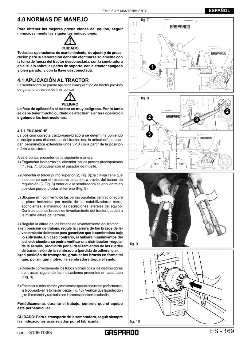
EMPLEO Y MANTENIMIENTO ESPAÑOL
ES - 169cod. G19501383
4.0 NORMAS DE MANEJOPara obtener las mejores presta ciones del equipo, seguir minuciosa mente las siguientes indicaciones:
CUIDADO
Todas las operaciones de mantenimiento, de ajuste y de prepa-ración para la elaboración deberán efectuarse solamente con la toma de fuerza del tractor desconectada, con la sembradora en el suelo sobre las patas de soporte, con el tractor apagado y bien parado, y con la llave desconectada.
4.1 APLICACIÓN AL TRACTORLa sembradora se puede aplicar a cualquier tipo de tractor provisto de gancho universal de tres puntos.
PELIGRO
La fase de aplicación al tractor es muy peligrosa. Por lo tanto se debe tener mucho cuidado de efectuar la entera operación siguiendo las instrucciones.
4.1.1 ENGANCHELa posición correcta tractor/sem-bradora se determina poniendo el equipo a una distancia tal del tractor, que la articulación de car-dán permanezca extendida unos 5-10 cm a partir de la posición máxima de cierre.
A este punto, proceder de la siguiente manera:1) Enganchar las barras del elevador en los pernos predispuestos
(1, Fig. 7). Bloquear con el pasador de muelle.
2) Conectar el tercer punto superior (2, Fig. 8); la clavija tiene que bloquearse con el respectivo pasador; a través del tensor de regulación (3, Fig. 8) tratar que la sembradora se encuentre en posición perpendicular al terreno (Fig. 8).
3) Bloquee el movimiento de las barras paralelas del tractor sobre el plano horizontal por medio de los estabilizadores corre-spondientes, eliminando las oscilaciones laterales del equipo. Controle que los brazos de levantamiento del tractor queden a la misma altura del terreno.
4) Regular la altura de los brazos de levantamiento del tractor: a) en posición de trabajo, regule la carrera de los brazos de le-
vantamiento del tractor para garantizar que la sembradora baje lo sufi ciente. En caso contrario, si hubiera hundimientos del lecho de siembra, se podría verifi car una distribución irregular de la semilla, producida por el deslizamientos de las ruedas de transmisión de la sembradora (pérdida de adherencia).
b) en posición de transporte, graduar los brazos en forma tal que, por ningún motivo, la sembradora toque el suelo.
5) Conecte correctamente los tubos hidráulicos a los distribuidores del tractor, siguiendo las indicaciones presentes en cada tubo (Fig. 9).
6) Engranar el árbol cardán y cerciorarse que se encuentre perfectamen-te bloqueado en la toma de fuerza (Fig. 10). Verifi car que la protección gire libremente y sujetarla con la correspondiente cadenilla.
Periódicamente, durante el trabajo, controle que el equipo esté perpendicular.
CUIDADO: Para el transporte de la sembradora, seguir siempre las indicaciones aconsejadas por el fabricante.
fi g. 8
fi g. 9
fi g. 7
1
2 32
3
fi g. 10
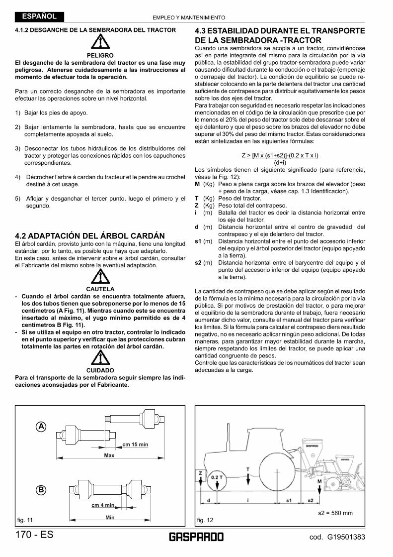
EMPLEO Y MANTENIMIENTOESPAÑOL
170 - ES cod. G19501383
4.1.2 DESGANCHE DE LA SEMBRADORA DEL TRACTOR
PELIGRO
El desganche de la sembradora del tractor es una fase muy peligrosa. Atenerse cuidadosamente a las instrucciones al momento de efectuar toda la operación.
Para un correcto desganche de la sembradora es importante efectuar las operaciones sobre un nivel horizontal.
1) Bajar los pies de apoyo.
2) Bajar lentamente la sembradora, hasta que se encuentre completamente apoyada al suelo.
3) Desconectar los tubos hidráulicos de los distribuidores del tractor y proteger las conexiones rápidas con los capuchones correspondientes.
4) Décrocher l’arbre à cardan du tracteur et le pendre au crochet destiné à cet usage.
5) Afl ojar y desganchar el tercer punto, luego el primero y el segundo.
4.2 ADAPTACIÓN DEL ÁRBOL CARDÁNEl árbol cardán, provisto junto con la máquina, tiene una longitud estándar; por lo tanto, es posible que haya que adaptarlo. En este caso, antes de intervenir sobre el árbol cardán, consultar el Fabricante del mismo sobre la eventual adaptación.
CAUTELA
- Cuando el árbol cardán se encuentra totalmente afuera, los dos tubos tienen que sobreponerse por lo menos de 15 centímetros (A Fig. 11). Mientras cuando este se encuentra insertado al máximo, el yugo mínimo permitido es de 4 centímetros B Fig. 11).
- Si se utiliza el equipo en otro tractor, controlar lo indicado en el punto superior y verifi car que las protecciones cubran totalmente las partes en rotación del árbol cardán.
CUIDADO
Para el transporte de la sembradora seguir siempre las indi-caciones aconsejadas por el Fabricante.
4.3 ESTABILIDAD DURANTE EL TRANSPORTE DE LA SEMBRADORA -TRACTORCuando una sembradora se acopla a un tractor, convirtiéndose así en parte integrante del mismo para la circulación por la vía pública, la estabilidad del grupo tractor-sembradora puede variar causando difi cultad durante la conducción o el trabajo (empenaje o derrapaje del tractor). La condición de equilibrio se puede re-stablecer colocando en la parte delantera del tractor una cantidad sufi ciente de contrapesos para distribuir equitativamente los pesos sobre los dos ejes del tractor.Para trabajar con seguridad es necesario respetar las indicaciones mencionadas en el código de la circulación que prescribe que por lo menos el 20% del peso del tractor solo debe descansar sobre el eje delantero y que el peso sobre los brazos del elevador no debe superar el 30% del peso del mismo tractor. Estas consideraciones están sintetizadas en las siguientes fórmulas:
Z > [M x (s1+s2)]-(0.2 x T x i)(d+i)
Los símbolos tienen el siguiente signifi cado (para referencia, véase la Fig. 12):M (Kg) Peso a plena carga sobre los brazos del elevador (peso
+ peso de la carga, véase cap. 1.3 Identifi cacion).T (Kg) Peso del tractor.Z (Kg) Peso total del contrapeso.i (m) Batalla del tractor es decir la distancia horizontal entre
los eje del tractor.d (m) Distancia horizontal entre el centro de gravedad del
contrapeso y el eje delantero del tractor.s1 (m) Distancia horizontal entre el punto del accesorio inferior
del equipo y el árbol posterior del tractor (equipo apoyado a la tierra).
s2 (m) Distancia horizontal entre el barycentre del equipo y el punto del accesorio inferior del equipo (equipo apoyado a la tierra).
La cantidad de contrapeso que se debe aplicar según el resultado de la fórmula es la mínima necesaria para la circulación por la vía pública. Si por motivos de prestación del tractor, o para mejorar el equilibrio de la sembradora durante el trabajo, fuera necesario aumentar dicho valor, consulte el manual del tractor para verifi car los límites. Si la fórmula para calcular el contrapeso diera resultado negativo, no es necesario aplicar ningún peso adicional. De todas maneras, para garantizar mayor estabilidad durante la marcha, siempre respetando los límites del tractor, se puede aplicar una cantidad congruente de pesos.Controle que las características de los neumáticos del tractor sean adecuadas a la carga.
s2 = 560 mmfi g. 12
cm 15 min
cm 4 min
Max
Min
A
B
fi g. 11
A
B
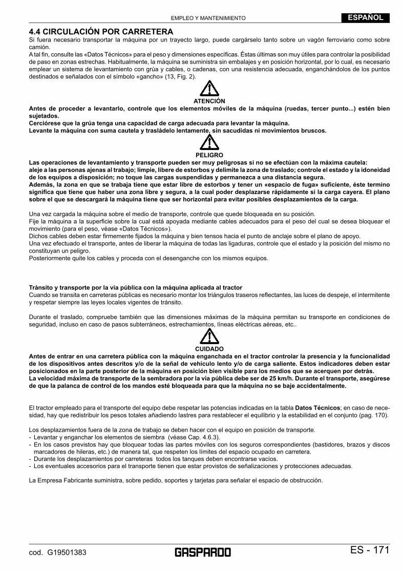
EMPLEO Y MANTENIMIENTO ESPAÑOL
ES - 171cod. G19501383
4.4 CIRCULACIÓN POR CARRETERASi fuera necesario transportar la máquina por un trayecto largo, puede cargárselo tanto sobre un vagón ferroviario como sobre camión.A tal fi n, consulte las «Datos Técnicos» para el peso y dimensiones específi cas. Éstas últimas son muy útiles para controlar la posibilidad de paso en zonas estrechas. Habitualmente, la máquina se suministra sin embalajes y en posición horizontal, por lo cual, es necesario emplear un sistema de levantamiento con grúa y cables, o cadenas, con una resistencia adecuada, enganchándolos de los puntos destinados e señalados con el símbolo «gancho» (13, Fig. 2).
ATENCIÓN
Antes de proceder a levantarlo, controle que los elementos móviles de la máquina (ruedas, tercer punto...) estén bien sujetados.Cerciórese que la grúa tenga una capacidad de carga adecuada para levantar la máquina.Levante la máquina con suma cautela y trasládelo lentamente, sin sacudidas ni movimientos bruscos.
PELIGRO
Las operaciones de levantamiento y transporte pueden ser muy peligrosas si no se efectúan con la máxima cautela:aleje a las personas ajenas al trabajo; limpie, libere de estorbos y delimite la zona de traslado; controle el estado y la idoneidad de los equipos a disposición; no toque las cargas suspendidas y permanezca a una distancia segura.Además, la zona en que se trabaja tiene que estar libre de estorbos y tener un «espacio de fuga» sufi ciente, éste termino signifi ca que tiene que haber una zona libre y segura, a la cual poder desplazarse rápidamente si la carga cayera. El plano sobre el que se descargará la máquina tiene que ser horizontal para evitar posibles desplazamientos de la carga.
Una vez cargada la máquina sobre el medio de transporte, controle que quede bloqueada en su posición.Fije la máquina a la superfi cie sobre la cual está apoyada mediante cables adecuados para el peso del cual se desea bloquear el movimiento (para el peso, véase «Datos Técnicos»).Dichos cables deben estar fi rmemente fi jados la máquina y bien tensos hacia el punto de anclaje sobre el plano de apoyo.Una vez efectuado el transporte, antes de liberar la máquina de todas las ligaduras, controle que el estado y la posición del mismo no constituyan un peligro. Posteriormente quite los cables y proceda con el desenganche con los mismos equipos.
Tránsito y transporte por la vía pública con la máquina aplicada al tractorCuando se transita en carreteras públicas es necesario montar los triángulos traseros refl ectantes, las luces de despeje, el intermitente y respetar siempre las leyes locales vigentes de tránsito.
Durante el traslado, compruebe también que las dimensiones máximas de la máquina permitan su transporte en condiciones de seguridad, incluso en caso de pasos subterráneos, estrechamientos, líneas eléctricas aéreas, etc..
CUIDADO
Antes de entrar en una carretera pública con la máquina enganchada en el tractor controlar la presencia y la funcionalidad de los dispositivos antes descritos y/o de la señal de vehículo lento y/o de carga saliente. Estos indicadores deben estar posicionados en la parte posterior de la máquina en posición bien visible para los medios que se acerquen por detrás.La velocidad máxima de transporte de la sembradora por la vía pública debe ser de 25 km/h. Durante el transporte, asegúrese de que la palanca de control de los mandos esté bloqueada para que la máquina no se baje accidentalmente.
El tractor empleado para el transporte del equipo debe respetar las potencias indicadas en la tabla Datos Técnicos; en caso de nece-sidad, hay que redistribuir los pesos totales añadiendo lastres para restablecer el equilibrio y la estabilidad en el conjunto (pag. 170).
Los desplazamientos fuera de la zona de trabajo se deben hacer con el equipo en posición de transporte.- Levantar y enganchar los elementos de siembra (véase Cap. 4.6.3).- En los casos previstos hay que bloquear todas las partes móviles con los seguros correspondientes (bastidores, brazos y discos
marcadores de hileras, etc.) de manera tal, que respeten los límites del espacio ocupado en carretera.- Durante los desplazamientos por carreteras todos los tanques deben encontrarse vacíos.- Los eventuales accesorios para el transporte tienen que estar provistos de señalizaciones y protecciones adecuadas.
La Empresa Fabricante suministra, sobre pedido, soportes y tarjetas para señalar el espacio de obstrucción.

EMPLEO Y MANTENIMIENTOESPAÑOL
172 - ES cod. G19501383
4.5 SELECCIÓN DE LA SEMILLA4.5.1 DISTRIBUIDOR DE SEMILLASEn el interior de los distribuidores (1, Fig. 13) se monta un disco (1, Fig. 14) seleccionado en función del tamaño de la semilla (la semilla no deberá poder pasar por el agujero).Las semillas que por succión obturan los agujeros del disco serán lanzadas en el terreno.La sembradora se entrega al cliente con una serie de discos de serie.La empresa Fabricante puede suministrarle al utilizador los juegos de discos siguientes: (véase pág. 175).
SUSTITUCIÓN DEL DISCO DE SIEMBRA Y REGULACIONES
CAUTELA
Todas las operaciones descritas en este párrafo tienen que ser efectuadas por personal experto, provisto de guantes protectores, en ambiente limpio y sin polvo.
- La sembradora tiene que estar limpia y seca, desconectada del tractor y situada de forma estable.
- Hay que montar sólo piezas limpias y en buen estado.- El disco tiene que estar montado con las espigas (1, Fig. 14)
dirigidas hacia el interior del distribuidor.- Si al disco le faltan espigas o están dobladas, signifi ca que
entraron cuerpos extraños en el distribuidor, en este caso habrá que sustituir el disco.
- Eventuales estriaduras circulares, no deberán sobrepasar 1/3 del espesor del disco.
- Apretar la tuerca de aletas de cierre de la tapa sólo con las manos (A, Fig. 13).
N.B. Cuando deba sustituir los discos gastados, se aconseja sustituir también la junta de la tapa.
Operaciones a efectuar:1) Levantar cada sembrador del piso de la manera siguiente: - enganchar el muelle en la posicion 1 (Fig. 15); - levantar el sembrador hasta que se enganche; - enganchar el muelle en la posicion 2 (Fig. 15);2) Si está montada, quitar el tornillo antirrebote (1, Fig. 16);3) Desenganchar el surcador (2 Fig. 16) sacando el muelle (3);4) Destornillar y sacar la tuerca de aletas (A, Fig. 13);5) Abrir la tapa del distribuidor;6) Introduzca o sustituya el disco;7) Si fuera necesario, regule la placa a prueba de desbordamiento
de las semillas, como indicado más adelante;8) Cierre la tapa, introduzca la arandela elástica y apriétela con
la tuerca de mariposa, enganche nuevamente el surcador, reinstale el tornillo a prueba de rebote (si estuviera previsto);
9) Regular el selector, como se indica más adelante;10) Descender el sembrador en el sentido contrario al indicado en
el punto 1.
fi g. 14
fi g. 15
fi g. 16
fi g. 13
1
1
2
3
21
A
1

EMPLEO Y MANTENIMIENTO ESPAÑOL
ES - 173cod. G19501383
SUSTITUCIÓN DE LA JUNTA DE LA TAPAControle periódicamente el desgaste uniforme sobre toda la superfi cie (A Fig. 17) de la junta de la tapa del distribuidor de semillas. La junta se debe cambiar antes de que la superfi cie (A Fig. 17), al desgastarse por efecto de la acción del disco, alcance la superfi cie «B». También hay que verifi car que no haya estrías a lo largo de toda la superfi cie «A», causadas por el disco.
EXPULSOR PARA SEMILLAUsar el expulsor de semillas de color gris claro (C, Fig. 18) para semillas de pequeñas dimensiones, con diámetro medio inferior a 3,5 mm (por ejemplo la remolacha confi tada). Usar el expulsor de semillas de color negro (D, Fig. 18) para semillas de dimensiones medias, diámetro medio de 3,5 a 7 mm (por ejemplo: maíz). Extraer los expulsores con dimensiones de semillas superio-res a 7 mm de diámetro medio. Desenrosque los tornillos (1, Fig. 18) y quite el expulsor (2).
MONTAJEColoque el expulsor (2) como muestra la fi gura 18. Presurando contra el borde de su aposita instalacion (3, Fig. 18). Fijarlo con el tornillo (1) en dotacion. El tornillo se deve montar como indicato en nel debujo. Non poner algun grueso snte el expulsor y su aloja-mento. Controle que el expulsor se adhiera al disco de siembra. Sustituya el expulsor cuando presente un desgaste evidente.
REGULACIÓN DEL SELECTORDesplazando el índice (1 Fig. 19 y 20) se gobierna un cursor (2 Fig. 19 y 20) que roza el disco en proximidad de los agujeros, provocando la caída de las semillas en exceso. El selector se regula tras cada cambio de semilla y disco, hacia los números bajos para las semillas pequeñas (Fig. 19) y viceversa para las semillas gruesas (Fig. 20). IMPORTANTE: el selector no regula la capacidad del fl ujo de aire en el distribuidor.
REGULACIÓN DE LA PLAQUETA DE ANTIDESBOR-DAMIENTOLa plaqueta para antidesbordamiento (1 Fig. 21) se puede ajustar en tres posiciones y defi ne la amplitud de la luz de entrada de las semillas (2 Fig. 21), de modo que las mismas no puedan salirse del distribuidor debido a una alimentación excesiva.El ajuste resulta particularmente necesario en presencia de ter-renos con fuertes inclinaciones o nos en-contramos en presencia de semillas pequeñas. En este caso, podría ser necesaria la sub-stitución de la plaqueta estándar con otra especial que se usará exclusivamente para las semillas pequeñas. El códigopara efectuar el pedido de la pieza es: G22270133. fi g. 21
fi g. 19
fi g. 20
fi g. 17
B A
BA
1
2
1
2
1
2
1
2 1
2
3 3
fi g. 18C D

EMPLEO Y MANTENIMIENTOESPAÑOL
174 - ES cod. G19501383
4.5.2 REGULACIÓNES PARA LA DISTRIBUCIÓN
TABLA INVERSIÓN SEMILLAS Tabla 2
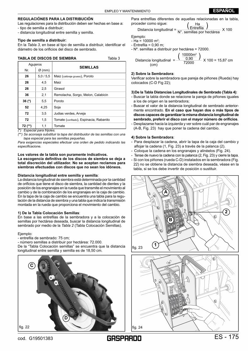
EMPLEO Y MANTENIMIENTO ESPAÑOL
ES - 175cod. G19501383
REGULACIÓNES PARA LA DISTRIBUCIÓNLas regulaciones para la distribución deben ser hechas en base a:- tipo de semilla a distribuir;- distancia longitudinal entre semilla y semilla.
Tipo de semilla a distribuir:En la Tabla 3, en base al tipo de semilla a distribuir, identifi car el diámetro de los orifi cios del disco de sembrado.
TABLA DE DISCOS DE SIEMBRA Tabla 3Agujeros
SEMILLASNr. Ø (mm)
26 5,0 / 5,5 Maiz (calibraje grueso), Poroto
26 4,5 Maiz
26 2,5 Girasol
36 2,1 Remolacha, Sorgo, Melon, Calabicin
36 (*) 5,5 Poroto
52 4,25 Soja
72 3,5 Judias verdes, Arveja
72 1,5 Tomate (confi tado), Espinacia, Rabanito
72 (**) 1,1 Tomate(*) Especial para frijoles.(**) Se aconseja substituir la tapa del distribuidor de las semillas con una
tapa especial para las semillas pequeñas.Para exigencias especiales efectuar una orden de pedido indicando las especifi cacione.
Los valores de la tabla son puramente indicativos. La escogencia defi nitiva de los discos de siembra se deja a total discreción del utilizador. No se aceptan reclamos para siembras efectuadas con discos que no sean los idóneos.
Distancia longitudinal entre semilla y semilla:La distancia longitudinal de siembra está determinada por la cantidad de orifi cios que tiene el disco de siembra, la cantidad de dientes y la posición de los engranajes en la rueda que transmite el movimiento al cambio y de la combinación de los engranajes en la caja de cambio. En la tapa de la caja de cambio se encuentra una tabla para la regu-lación de la distancia de siembra y una tabla que indica la transmisión montada en la rueda que proporciona el movimiento del cambio.
1) De la Tabla Colocación Semillas:En base a las entrefi las de la sembradora y a la colocación de semillas por hectárea deseada, buscar la distancia longitudinal de sembrado por medio de la Tabla 2 (Tabla Colocación Semillas).
Ejemplo:- entrefi la de sembrado: 75 cm;- número semillas a distribuir por hectárea: 72.000.De la “Tabla Colocación semillas” se encuentra que la distancia longitudinal entre semilla y semilla es de 18,50 cm.
Para entrefi las diferentes de aquellas relacionadas en la tabla, proceder como sigue:
Ejemplo:- Ha = 10000 m2;- Entrefi la = 0,90 m;- Nº. semillas a distribuir por hectárea = 72000.
2) Sobre la Sembradora:Verifi car sobre la sembradora que pareja de piñones (Rueda) hay colocados (C-D Fig 22);
3) De la Tabla Distancias Longitudinales de Sembrado (Tabla 4):- Buscar la tabla donde se relacione la pareja de piñones iguales
a los de origen en la sembradora;- Buscar el valor de la distancia longitudinal de sembrado anterior-
mente encontrado. En el caso que hayan dos o más tipos de discos capaces de garantizar la misma distancia longitudinal de sembrado, preferir el disco con el mayor número de orifi cios.
- Desplazarse hacia la izquierda y ver sobre cuál par de engranajes (A-B, Fig. 23) hay que poner la cadena del cambio.
4) Sobre la Sembradora:- Para desplazar la cadena, abrir la tapa de la caja del cambio y
afl ojar la cadena (1, Fig. 23) a través de la palanca (2).- Coloque la cadena en los engranajes y alinéelos (Fig. 24).- Tense de nuevo la cadena con la palanca (2, Fig. 23) y cierre la tapa.- Si con los piñones (rueda C-D) instalados en la sembradora (Fig.
22) no se obtiene la distancia de siembra deseada, véase en la tabla, si se los debe invertir de posición o sustituir.
( )10000m2
0,90 X 100 = 15,87 cm72000Distancia longitudinal =(cm)
Distancia longitudinal =( )Ha
Entrefi la X 100N°. semillas por hectárea
fi g. 23
fi g. 24
1
2
A
B
fi g. 22
C
D

EMPLEO Y MANTENIMIENTOESPAÑOL
176 - ES cod. G19501383
TABLA DISTANCIA LONGITUDINAL DE SIEMBRA (Tabla 4)Las distancias de siembra que se muestran en la tabla constituyen solo valores indicativos porque dependen de las diferentes condiciones de trabajo y del terreno. Por eso se recomienda controlar prácticamente la distancia real de las semillas. Se aconseja recorrer algunos met-ros de siembra y comprobar que la deposición de la semilla sea correcta y, sobre todo, controlar que el número de semillas por metro lineal corresponda al deseado. La Empresa se exime de toda responsabilidad debida a incongruencias entre los valores de la tabla y los valores reales encontrados.
cmcm
cmcm
cm23
- 17
15,6
12,0
8,7
6,0
4,3
23 -
1816
,612
,79,
26,
34,
623
- 19
17,5
13,5
9,7
6,7
4,8
23 -
2018
,414
,110
,27,
05,
123
- 21
19,3
14,8
10,7
7,4
5,3
23 -
2220
,315
,611
,27,
85,
623
- 23
21,2
16,3
11,7
8,1
5,8
16 -
1722
,517
,312
,58,
66,
216
- 18
23,8
18,3
13,2
9,1
6,6
16 -
1925
,119
,314
,09,
67,
016
- 20
26,5
20,4
14,7
10,2
7,3
16 -
2127
,821
,415
,410
,77,
716
- 22
29,1
22,4
16,2
11,2
8,1
16 -
2330
,423
,416
,911
,78,
4
cmcm
cmcm
cm23
- 17
10,9
8,4
6,0
4,2
3,0
23 -
1811
,58,
96,
44,
43,
223
- 19
12,2
9,4
6,8
4,7
3,4
23 -
2012
,89,
97,
14,
93,
523
- 21
13,5
10,4
7,4
5,2
3,7
23 -
2214
,110
,87,
85,
43,
923
- 23
14,7
11,3
8,2
5,6
4,1
16 -
1715
,612
,08,
76,
04,
316
- 18
16,6
12,8
9,2
6,4
4,6
16 -
1917
,513
,59,
76,
74,
816
- 20
18,4
14,2
10,2
7,1
5,1
16 -
2119
,315
,010
,77,
55,
316
- 22
20,2
15,6
11,3
7,8
5,6
16 -
2321
,216
,311
,88,
15,
9
cmcm
cmcm
cm23
- 17
22,5
17,3
12,5
8,6
6,2
23 -
1823
,818
,313
,29,
16,
623
- 19
25,2
19,4
14,0
9,7
7,0
23 -
2026
,520
,414
,710
,27,
323
- 21
27,8
21,4
15,4
10,7
7,7
23 -
2229
,122
,416
,211
,28,
123
- 23
30,4
23,4
17,0
11,7
8,5
16 -
1732
,424
,918
,012
,49,
016
- 18
34,3
26,4
19,0
13,2
9,3
16 -
1936
,227
,820
,113
,410
,016
- 20
38,0
29,3
21,2
14,6
10,6
16 -
2140
,030
,822
,215
,411
,116
- 22
41,9
32,2
23,4
16,1
11,7
16 -
2343
,833
,724
,316
,812
,1
Cam
bio
Gea
rbox
A
- B
Ruo
ta
Whe
el
C
- D
Cam
bio
Gea
rbox
A
- B
Ruo
ta
Whe
el
C
- D
Cam
bio
Gea
rbox
A
- B
Ruo
ta
Whe
el
C
- D
2026
3652
72
2026
3652
72
2026
3652
72
2026
3652
72
2026
3652
72
C D
A23
16
Cod
. G19
7014
13
Ruo
taW
heel
R
adR
oue
Rue
daКо
лесо
23 2
2 21
20
19 1
8 17
B
Cam
bio
-Gea
rbox
Get
riebe
-B
oitê
vit.
C
ambi
o -С
мена
23
23
23
16
16
23
6,50
/80-
15
cmcm
cmcm
cm23
- 17
14,9
11,5
8,3
5,7
4,2
23 -
1815
,812
,28,
86,
14,
423
- 19
16,7
12,8
9,3
6,4
4,7
23 -
2017
,613
,59,
86,
74,
923
- 21
18,4
14,2
10,2
7,1
5,1
23 -
2219
,314
,910
,77,
45,
423
- 23
20,2
15,5
11,2
7,7
5,6
16 -
1721
,416
,511
,98,
26,
016
- 18
22,7
17,5
12,6
8,7
6,3
16 -
1924
,018
,513
,39,
26,
716
- 20
25,2
19,4
14,0
9,7
7,0
16 -
2126
,520
,414
,710
,27,
416
- 22
27,8
21,4
15,4
10,7
7,7
16 -
2329
,122
,516
,111
,28,
1
cmcm
cmcm
cm23
- 17
10,4
8,0
5,8
4,0
2,9
23 -
1811
,08,
56,
14,
23,
023
- 19
11,7
9,0
6,5
4,5
3,2
23 -
2012
,29,
46,
84,
73,
423
- 21
12,9
9,9
7,1
1,9
3,5
23 -
2213
,510
,37,
55,
13,
723
- 23
14,0
10,8
7,8
5,4
3,9
16 -
1715
,011
,58,
35,
74,
116
- 18
15,8
12,2
8,8
6,1
4,4
16 -
1916
,712
,99,
36,
44,
616
- 20
17,6
13,5
9,8
6,7
4,9
16 -
2118
,514
,210
,37,
15,
116
- 22
19,4
14,9
10,8
7,4
5,4
16 -
2320
,215
,511
,37,
75,
6
cmcm
cmcm
cm23
- 17
21,4
16,5
11,9
8,2
5,9
23 -
1822
,717
,512
,68,
76,
323
- 19
24,0
18,4
13,3
9,2
6,6
23 -
2025
,219
,414
,09,
77,
023
- 21
26,5
20,4
14,7
10,2
7,3
23 -
2227
,821
,315
,410
,67,
723
- 23
29,0
22,3
16,1
11,1
8,0
16 -
1730
,823
,717
,111
,88,
516
- 18
32,7
25,1
18,1
12,5
9,0
16 -
1934
,526
,519
,113
,29,
516
- 20
36,2
27,9
20,1
13,9
10,0
16 -
2138
,129
,321
,114
,610
,616
- 22
39,9
30,7
22,1
15,3
11,0
16 -
2341
,732
,123
,216
,011
,6
Ruo
ta
Whe
el
C
- D
Cam
bio
Gea
rbox
A
- B
Ruo
ta
Whe
el
C
- D
Cam
bio
Gea
rbox
A
- B
Ruo
ta
Whe
el
C
- D
Cam
bio
Gea
rbox
A
- B20
2636
5272
2026
3652
72
2026
3652
72
2026
3652
72
2026
3652
72
C D
A23
16
Cod
. G19
7014
03
Ruo
taW
heel
R
adR
oue
Rue
daКо
лесо
23 2
2 21
20
19 1
8 17
B
5.00
-15
Cam
bio
-Gea
rbox
Get
riebe
-B
oitê
vit.
C
ambi
o -С
мена
23
23
23
16
16
23

EMPLEO Y MANTENIMIENTO ESPAÑOL
ES - 177cod. G19501383
cmcm
cmcm
cm23
- 17
17,5
13,5
9,7
6,7
4,9
23 -
1818
,514
,310
,37,
15,
223
- 19
19,6
15,1
10,9
7,5
5,4
23 -
2020
,615
,911
,47,
95,
723
- 21
21,6
16,6
12,0
8,3
6,0
23 -
2222
,717
,412
,68,
76,
323
- 23
23,7
18,2
13,2
9,1
6,6
16 -
1725
,219
,414
,09,
77,
016
- 18
26,7
20,5
14,8
10,3
7,4
16 -
1928
,121
,615
,610
,87,
816
- 20
29,6
22,8
16,5
11,4
8,2
16 -
2131
,123
,917
,312
,08,
616
- 22
32,6
25,1
18,1
12,5
9,1
16 -
2334
,126
,218
,913
,19,
5
cmcm
cmcm
cm23
- 17
12,2
9,4
6,8
4,7
3,4
23 -
1812
,99,
97,
25,
03,
623
- 19
13,6
10,5
7,6
5,2
3,8
23 -
2014
,311
,08,
05,
54,
023
- 21
15,1
11,6
8,4
5,8
4,2
23 -
2215
,812
,18,
86,
14,
423
- 23
16,5
12,7
9,2
6,3
4,6
16 -
1717
,513
,59,
76,
74,
916
- 18
18,5
14,3
10,3
7,1
5,2
16 -
1919
,615
,110
,97,
55,
416
- 20
20,6
15,9
11,4
7,9
5,7
16 -
2121
,616
,612
,08,
36,
016
- 22
22,7
17,4
12,6
8,7
6,3
16 -
2323
,718
,213
,29,
16,
6
cmcm
cmcm
cm23
- 17
25,2
19,4
14,0
9,7
7,0
23 -
1826
,720
,514
,810
,37,
423
- 19
28,1
21,6
15,6
10,8
7,8
23 -
2029
,622
,816
,511
,48,
223
- 21
31,1
23,9
17,3
12,0
8,6
23 -
2232
,625
,118
,112
,59,
123
- 23
34,1
26,2
18,9
13,1
9,5
16 -
1736
,227
,820
,113
,910
,116
- 18
38,3
29,5
21,3
14,7
10,6
16 -
1940
,531
,122
,515
,611
,216
- 20
42,6
32,8
23,7
16,4
11,8
16 -
2144
,734
,424
,817
,212
,416
- 22
46,8
36,0
26,0
18,0
13,0
16 -
2349
,037
,727
,218
,813
,6
Ruo
ta
Whe
el
C
- D
Cam
bio
Gea
rbox
A
- B
Ruo
ta
Whe
el
C
- D
Cam
bio
Gea
rbox
A
- B
Ruo
ta
Whe
el
C
- D
Cam
bio
Gea
rbox
A
- B20
2636
5272
2026
3652
72
2026
3652
72
2026
3652
72
2026
3652
72
C D
A23
16
Cod
. G19
7014
52
Ruo
taW
heel
R
adR
oue
Rue
daКо
лесо
23 2
2 21
20
19 1
8 17
B
Cam
bio
-Gea
rbox
Get
riebe
-B
oitê
vit.
C
ambi
o -С
мена
23
23
23
16
16
23
7,50
-16
cmcm
cmcm
cm23
- 17
16,3
12,5
9,0
6,3
4,5
23 -
1817
,213
,29,
66,
64,
823
- 19
18,2
14,0
10,1
7,0
5,0
23 -
2019
,114
,710
,67,
45,
323
- 21
20,1
15,5
11,2
7,7
5,6
23 -
2221
,016
,211
,78,
15,
823
- 23
22,0
16,9
12,2
8,5
6,1
16 -
1723
,418
,013
,09,
06,
516
- 18
24,8
19,0
13,8
9,5
6,9
16 -
1926
,120
,114
,510
,07,
316
- 20
27,5
21,2
15,3
10,6
7,6
16 -
2128
,922
,216
,011
,18,
016
- 22
30,3
23,3
16,8
11,6
8,4
16 -
2331
,624
,317
,612
,28,
8
cmcm
cmcm
cm23
- 17
11,3
8,7
6,3
4,4
3,1
23 -
1812
,09,
26,
74,
63,
323
- 19
12,6
9,7
7,0
4,9
3,5
23 -
2013
,310
,27,
45,
13,
723
- 21
14,0
10,7
7,8
5,4
3,9
23 -
2214
,611
,38,
15,
64,
123
- 23
15,3
11,8
8,5
5,9
4,3
16 -
1716
,312
,59,
06,
34,
516
- 18
17,2
13,2
9,6
6,6
4,8
16 -
1918
,214
,010
,17,
05,
016
- 20
19,1
14,7
10,6
7,4
5,3
16 -
2120
,115
,511
,27,
75,
616
- 22
21,0
16,2
11,7
8,1
5,8
16 -
2322
,016
,912
,28,
86,
1
cmcm
cmcm
cm23
- 17
23,4
18,0
13,0
9,0
6,5
23 -
1824
,819
,013
,89,
56,
923
- 19
26,1
20,1
14,5
10,0
7,3
23 -
2027
,521
,215
,310
,67,
623
- 21
28,9
22,2
16,0
11,1
8,0
23 -
2230
,323
,316
,811
,68,
423
- 23
31,6
24,3
17,6
12,2
8,8
16 -
1733
,625
,818
,712
,99,
316
- 18
35,6
27,4
19,8
13,7
9,9
16 -
1937
,628
,920
,914
,410
,416
- 20
39,5
30,4
22,0
15,2
11,0
16 -
2141
,531
,923
,116
,011
,516
- 22
43,5
33,4
24,2
16,7
12,1
16 -
2345
,535
,025
,317
,512
,6
Cam
bio
Gea
rbox
A
- B
Ruo
ta
Whe
el
C
- D
Cam
bio
Gea
rbox
A
- B
Ruo
ta
Whe
el
C
- D
Cam
bio
Gea
rbox
A
- B
Ruo
ta
Whe
el
C
- D
2026
3652
72
2026
3652
72
2026
3652
72
2026
3652
72
2026
3652
72
C D
A23
16
Cod
. G19
7031
62
23 2
2 21
20
19 1
8 17
B
Cam
bio
-Gea
rbox
Get
riebe
-B
oitê
vit.
C
ambi
o -С
мена
23
23
23
16
16
23
Ruo
ta fu
ori c
arre
ggia
taW
heel
out
whe
elba
seR
ad a
ssue
rhal
b sc
hlep
pers
pur
Rou
e ho
rs v
oie
du tr
acte
urR
ueda
est
erio
rВнешни
е коле
са перед
ачи
6,50
/80-
15
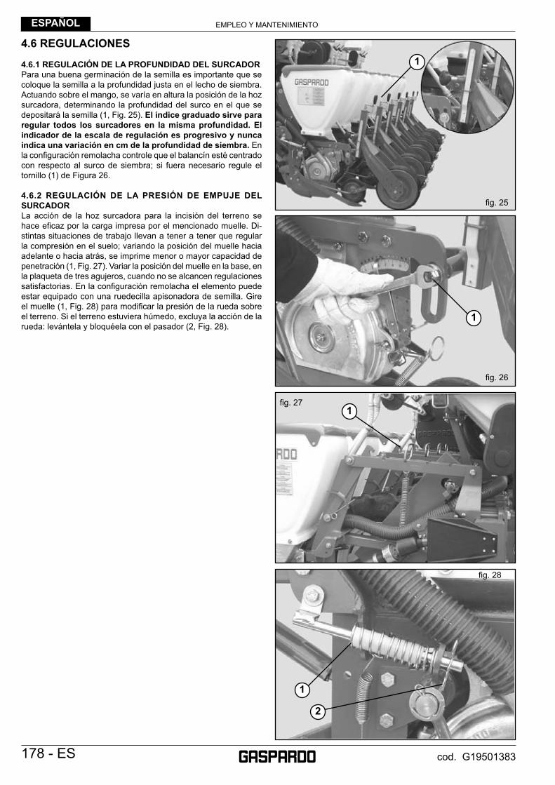
EMPLEO Y MANTENIMIENTOESPAÑOL
178 - ES cod. G19501383
4.6 REGULACIONES
4.6.1 REGULACIÓN DE LA PROFUNDIDAD DEL SURCADORPara una buena germinación de la semilla es importante que se coloque la semilla a la profundidad justa en el lecho de siembra. Actuando sobre el mango, se varía en altura la posición de la hoz surcadora, determinando la profundidad del surco en el que se depositará la semilla (1, Fig. 25). El índice graduado sirve para regular todos los surcadores en la misma profundidad. El indicador de la escala de regulación es progresivo y nunca indica una variación en cm de la profundidad de siembra. En la confi guración remolacha controle que el balancín esté centrado con respecto al surco de siembra; si fuera necesario regule el tornillo (1) de Figura 26.
4.6.2 REGULACIÓN DE LA PRESIÓN DE EMPUJE DEL SURCADORLa acción de la hoz surcadora para la incisión del terreno se hace efi caz por la carga impresa por el mencionado muelle. Di-stintas situaciones de trabajo llevan a tener a tener que regular la compresión en el suelo; variando la posición del muelle hacia adelante o hacia atrás, se imprime menor o mayor capacidad de penetración (1, Fig. 27). Variar la posición del muelle en la base, en la plaqueta de tres agujeros, cuando no se alcancen regulaciones satisfactorias. En la confi guración remolacha el elemento puede estar equipado con una ruedecilla apisonadora de semilla. Gire el muelle (1, Fig. 28) para modifi car la presión de la rueda sobre el terreno. Si el terreno estuviera húmedo, excluya la acción de la rueda: levántela y bloquéela con el pasador (2, Fig. 28).
fi g. 25
fi g. 27
fi g. 26
fi g. 28
1
1
1
1
2
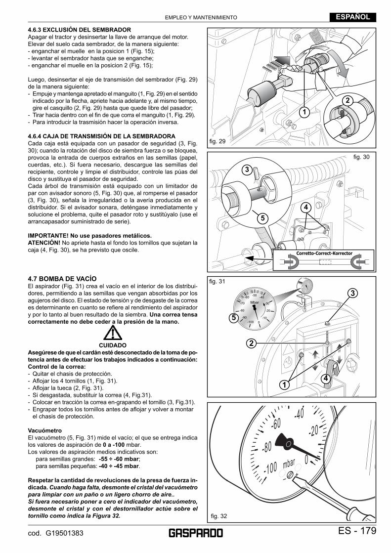
EMPLEO Y MANTENIMIENTO ESPAÑOL
ES - 179cod. G19501383
4.6.3 EXCLUSIÓN DEL SEMBRADORApagar el tractor y desinsertar la llave de arranque del motor.Elevar del suelo cada sembrador, de la manera siguiente:- enganchar el muelle en la posicion 1 (Fig. 15);- levantar el sembrador hasta que se enganche;- enganchar el muelle en la posicion 2 (Fig. 15);
Luego, desinsertar el eje de transmisión del sembrador (Fig. 29) de la manera siguiente:- Empuje y mantenga apretado el manguito (1, Fig. 29) en el sentido
indicado por la fl echa, apriete hacia adelante y, al mismo tiempo, gire el casquillo (2, Fig. 29) hasta que quede libre del pasador;
- Tirar hacia dentro con el fi n de que corra el manguito (1, Fig. 29).- Para introducir la trasmisión hacer la operación inversa.
4.6.4 CAJA DE TRANSMISIÓN DE LA SEMBRADORACada caja está equipada con un pasador de seguridad (3, Fig. 30); cuando la rotación del disco de siembra fuerza o se bloquea, provoca la entrada de cuerpos extraños en las semillas (papel, cuerdas, etc.). Si fuera necesario, descargue las semillas del recipiente, controle y limpie el distribuidor, controle las púas del disco y sustituya el pasador de seguridad.Cada árbol de transmisión está equipado con un limitador de par con avisador sonoro (5, Fig. 30) que, al romperse el pasador (3, Fig. 30), señala la irregularidad o la avería producida en el distribuidor. Si el avisador sonara, deténgase inmediatamente y solucione el problema, quite el pasador roto y sustitúyalo (use el arrancapasador suministrado de serie).
IMPORTANTE! No use pasadores metálicos.ATENCIÓN! No apriete hasta el fondo los tornillos que sujetan la caja (4, Fig. 30), se ha previsto que oscile.
4.7 BOMBA DE VACÍOEl aspirador (Fig. 31) crea el vacío en el interior de los distribui-dores, permitiendo a las semillas que vengan absorbidas por los agujeros del disco. El estado de tensión y de desgaste de la correa es determinante en cuanto se refi ere al rendimiento del aspirador y por lo tanto al buen resultado de la siembra. Una correa tensa correctamente no debe ceder a la presión de la mano.
CUIDADO
Asegúrese de que el cardán esté desconectado de la toma de po-tencia antes de efectuar los trabajos indicados a continuación:Control de la correa:- Quitar el chasis de protección.- Afl ojar los 4 tornillos (1, Fig. 31).- Afl ojar la tueca (2, Fig. 31).- Si desgastada, substituir la correa (4, Fig.31).- Colocar en tracción la correa en-grapando el tornillo (3, Fig.31).- Engrapar todos los tornillos antes de afl ojar y volver a montar el chasis de protección.
VacuómetroEl vacuómetro (5, Fig. 31) mide el vacío; el que se entrega indica los valores de aspiración de 0 a -100 mbar.Los valores de aspiración medios indicativos son: para semillas grandes: -55 ÷ -60 mbar; para semillas pequeñas: -40 ÷ -45 mbar.
Respetar la cantidad de revoluciones de la presa de fuerza in-dicada. Cuando haga falta, desmonte el cristal del vacuómetro para limpiar con un paño o un ligero chorro de aire..Si fuera necesario poner a cero el indicador del vacuómetro, desmonte el cristal y con el destornillador actúe sobre el tornillo como indica la Figura 32.
fi g. 29
Corretto-Correct-Korrector
fi g. 30
12
45
3
fi g. 31
-60
-80
-100 0
-20-40
mbar
fi g. 32
-50-60
-70
-80
-90-100 0
-10
-20
-30
-40
Mbar
1
3
2
4
5
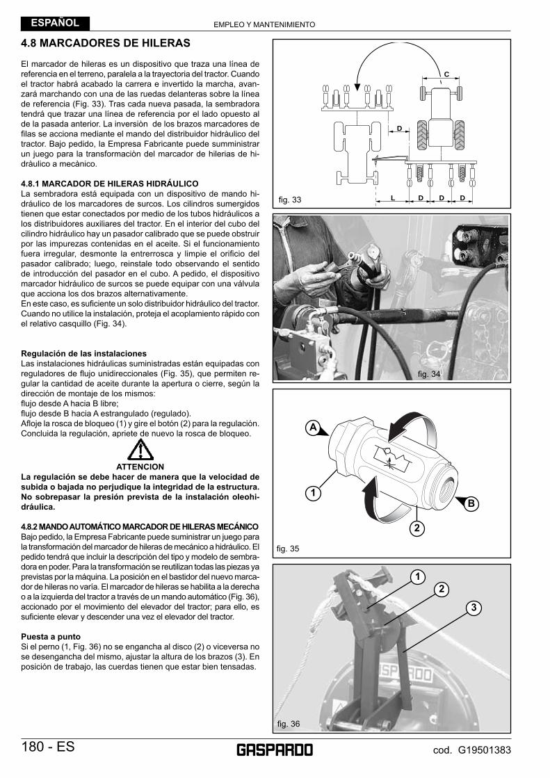
EMPLEO Y MANTENIMIENTOESPAÑOL
180 - ES cod. G19501383
4.8 MARCADORES DE HILERAS
El marcador de hileras es un dispositivo que traza una línea de referencia en el terreno, paralela a la trayectoria del tractor. Cuando el tractor habrá acabado la carrera e invertido la marcha, avan-zará marchando con una de las ruedas delanteras sobre la línea de referencia (Fig. 33). Tras cada nueva pasada, la sembradora tendrá que trazar una línea de referencia por el lado opuesto al de la pasada anterior. La inversiòn de los brazos marcadores de fi las se acciona mediante el mando del distribuidor hidràulico del tractor. Bajo pedido, la Empresa Fabricante puede sumministrar un juego para la transformaciòn del marcador de hilerias de hi-dràulico a mecànico.
4.8.1 MARCADOR DE HILERAS HIDRÁULICOLa sembradora está equipada con un dispositivo de mando hi-dráulico de los marcadores de surcos. Los cilindros sumergidos tienen que estar conectados por medio de los tubos hidráulicos a los distribuidores auxiliares del tractor. En el interior del cubo del cilindro hidráulico hay un pasador calibrado que se puede obstruir por las impurezas contenidas en el aceite. Si el funcionamiento fuera irregular, desmonte la entrerrosca y limpie el orifi cio del pasador calibrado; luego, reinstale todo observando el sentido de introducción del pasador en el cubo. A pedido, el dispositivo marcador hidráulico de surcos se puede equipar con una válvula que acciona los dos brazos alternativamente. En este caso, es sufi ciente un solo distribuidor hidráulico del tractor. Cuando no utilice la instalación, proteja el acoplamiento rápido con el relativo casquillo (Fig. 34).
Regulación de las instalacionesLas instalaciones hidráulicas suministradas están equipadas con reguladores de fl ujo unidireccionales (Fig. 35), que permiten re-gular la cantidad de aceite durante la apertura o cierre, según la dirección de montaje de los mismos:fl ujo desde A hacia B libre;fl ujo desde B hacia A estrangulado (regulado).Afl oje la rosca de bloqueo (1) y gire el botón (2) para la regulación. Concluida la regulación, apriete de nuevo la rosca de bloqueo.
ATTENCION
La regulación se debe hacer de manera que la velocidad de subida o bajada no perjudique la integridad de la estructura. No sobrepasar la presión prevista de la instalación oleohi-dráulica.
4.8.2 MANDO AUTOMÁTICO MARCADOR DE HILERAS MECÁNICOBajo pedido, la Empresa Fabricante puede suministrar un juego para la transformación del marcador de hileras de mecánico a hidráulico. El pedido tendrá que incluir la descripción del tipo y modelo de sembra-dora en poder. Para la transformación se reutilizan todas las piezas ya previstas por la máquina. La posición en el bastidor del nuevo marca-dor de hileras no varía. El marcador de hileras se habilita a la derecha o a la izquierda del tractor a través de un mando automático (Fig. 36), accionado por el movimiento del elevador del tractor; para ello, es sufi ciente elevar y descender una vez el elevador del tractor.
Puesta a puntoSi el perno (1, Fig. 36) no se engancha al disco (2) o viceversa no se desengancha del mismo, ajustar la altura de los brazos (3). En posición de trabajo, las cuerdas tienen que estar bien tensadas.
fi g. 36
12
3
fi g. 33
fi g. 35
fi g. 34
L
D
C
D D D
1
2
A
B
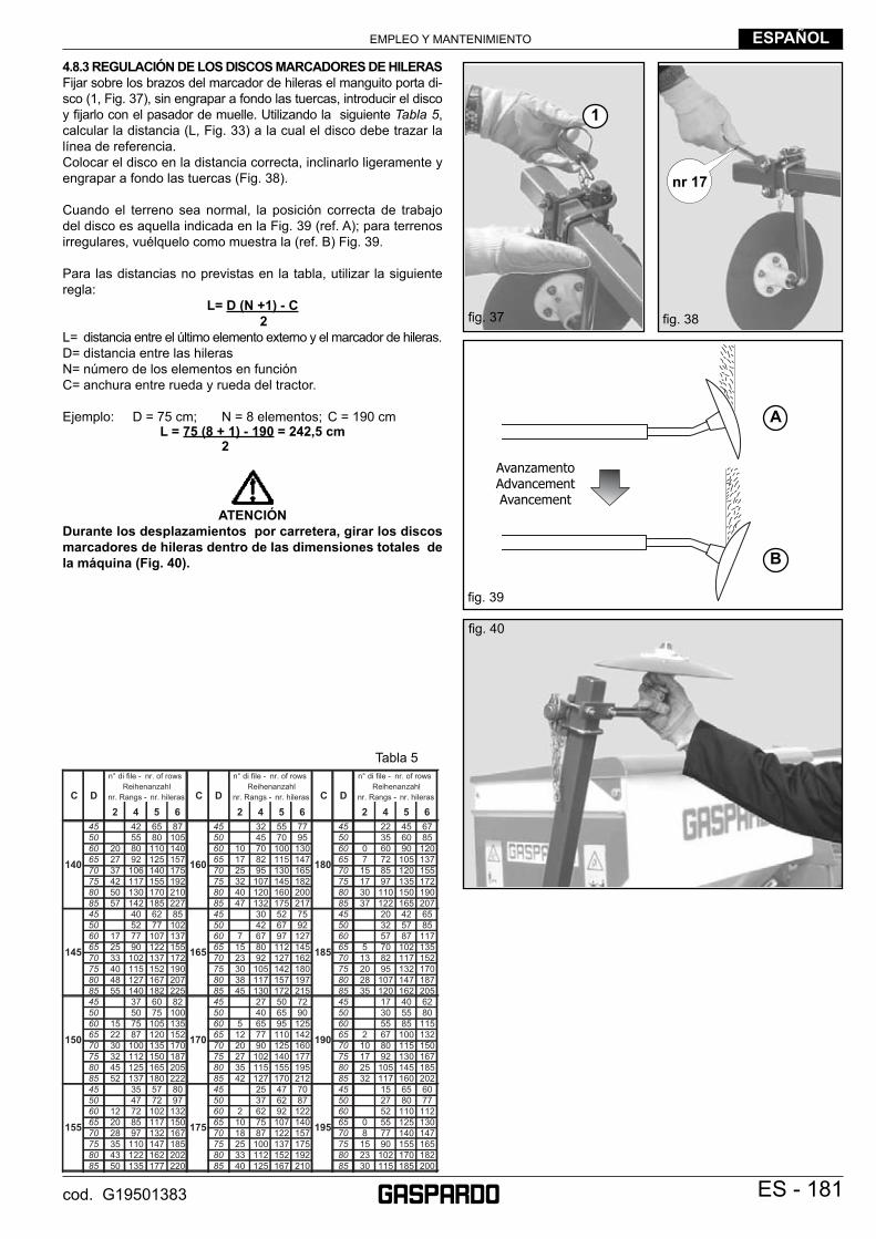
EMPLEO Y MANTENIMIENTO ESPAÑOL
ES - 181cod. G19501383
4.8.3 REGULACIÓN DE LOS DISCOS MARCADORES DE HILERASFijar sobre los brazos del marcador de hileras el manguito porta di-sco (1, Fig. 37), sin engrapar a fondo las tuercas, introducir el disco y fi jarlo con el pasador de muelle. Utilizando la siguiente Tabla 5, calcular la distancia (L, Fig. 33) a la cual el disco debe trazar la línea de referencia. Colocar el disco en la distancia correcta, inclinarlo ligeramente y engrapar a fondo las tuercas (Fig. 38).
Cuando el terreno sea normal, la posición correcta de trabajo del disco es aquella indicada en la Fig. 39 (ref. A); para terrenos irregulares, vuélquelo como muestra la (ref. B) Fig. 39.
Para las distancias no previstas en la tabla, utilizar la siguiente regla:
L= D (N +1) - C 2
L= distancia entre el último elemento externo y el marcador de hileras.D= distancia entre las hileras N= número de los elementos en funciónC= anchura entre rueda y rueda del tractor.
Ejemplo: D = 75 cm; N = 8 elementos; C = 190 cmL = 75 (8 + 1) - 190 = 242,5 cm
2
ATENCIÓN
Durante los desplazamientos por carretera, girar los discos marcadores de hileras dentro de las dimensiones totales de la máquina (Fig. 40).
fi g. 40
fi g. 39
AvanzamentoAdvancementAvancement
nr 17
fi g. 38fi g. 37
Tabla 5
1
A
B
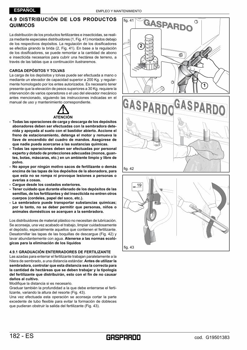
EMPLEO Y MANTENIMIENTOESPAÑOL
182 - ES cod. G19501383
4.9 DISTRIBUCIÓN DE LOS PRODUCTOS QUIMICOS
La distribución de los productos fertilizantes e insecticidas, se reali-za mediante especiales distribuidores (1, Fig. 41) montados debajo de los respectivos depósitos. La regulación de los dosifi cadores se efectúa girando la brida (2, Fig. 41). En base a la regulación de los dosifi cadores, se puede remontar a la cantidad de abono e insecticida necesarios para cubrir una hectárea de terreno, a través de las tablas que a continuación ilustraremos.
CARGA DEPÓSITOS Y TOLVAS La carga de los depósitos y tolvas puede ser efectuada a mano o mediante un elevador de capacidad superior a 200 Kg. y regular-mente homologado por los entes autorizados. Es necesario tener presente que la elevación de pesos superiores a 30 Kg. requiere la intervención de varios operadores o el uso del elevador mecánico antes mencionado, siguiendo las instrucciones indicadas en el manual de uso y mantenimiento correspondiente.
ATENCIÓN
- Todas las operaciones de carga y descarga de los depósitos abonadores deben ser efectuadas con la sembradora dete-nida y apoyada al suelo con el bastidor abierto. Accione el freno de estacionamiento, detenga el motor y remueva la llave de encendido del cuadro de mandos. Asegúrese de que nadie pueda acercarse a las sustancias químicas.
- Todas las operaciones deben ser efectuadas por personal experto y dotado de protecciones adecuadas (monos, guan-tes, botas, máscaras, etc.) en un ambiente limpio y libre de polvo.
- No apoye por ningún motivo sacos de fertilizante o demás encima de las tapas de los depósitos de la abonadora, para que esta no se rompa ni provoque lesiones a personas o averías a cosas.
- Cargue desde los costados exteriores.- Tener cuidado que durante ellenado de los depósitos de las
semillas, de los fertilizantes y del insecticida no entren otros cuerpos (cordeles, papel del saco, etc.).
- La sembradora puede transportar substancias químicas; por lo tanto, no se deber permitir que personas, niños o animales domésticos se acerquen a la sembradora.
Los distribuidores de material plástico no necesitan de lubricación. Se aconseja, una vez acabado el trabajo, limpiar cuidadosamente el depósito, especialmente aquellos que contienen el fertilizante. Desatornillar las tapas de las boquillas de descargue (Fig. 42) y lavar abundantemente con agua. Atenerse a las normas ecoló-gicas para la eliminación de los líquidos
4.9.1 GRADUACIÓN ENTERRADORES DE FERTILIZANTELas azadas para enterrar el fertilizante trabajan paralelamente a la hilera de sembrado, a una distancia estándar. Antes de utilizar la sembradora, controlar que esta distancia sea la correcta para la cantidad de hectáreas que se deben trabajar y la tipología del fertilizante que distribuirán, esto con el fi n de no causar daños al cultivo. Modifi que la distancia si es necesario. Graduar también la profundidad a la que debe enterrarse el ferti-lizante, variando la altura del resorte (Fig. 43).Una vez efectuada esta operación se aconseja cortar la parte excedente de tubo fl exible para evitar la formación de dobleces que pudieran obstruir la salida del fertilizante (Fig. 43).
11 1
NR -.........19
fi g. 41
fi g. 43
fi g. 42
1
2
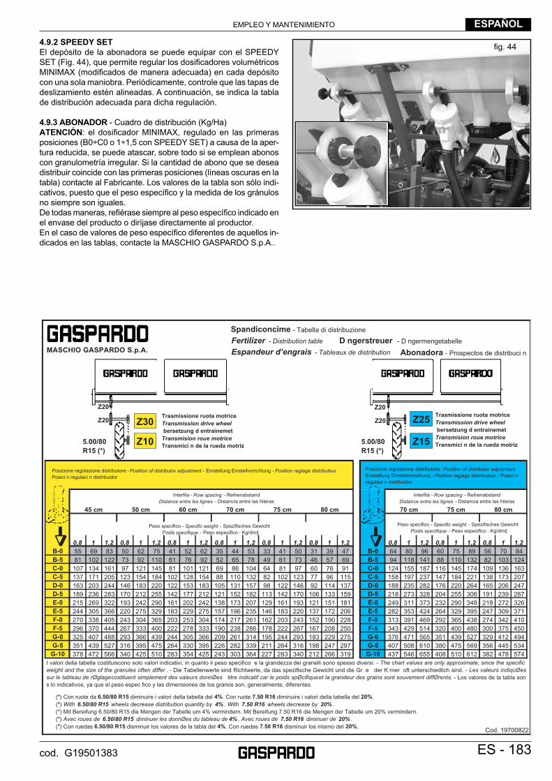
EMPLEO Y MANTENIMIENTO ESPAÑOL
ES - 183cod. G19501383
4.9.2 SPEEDY SETEl depósito de la abonadora se puede equipar con el SPEEDY SET (Fig. 44), que permite regular los dosifi cadores volumétricos MINIMAX (modifi cados de manera adecuada) en cada depósito con una sola maniobra. Periódicamente, controle que las tapas de deslizamiento estén alineadas. A continuación, se indica la tabla de distribución adecuada para dicha regulación.
4.9.3 ABONADOR - Cuadro de distribución (Kg/Ha)ATENCIÓN: el dosifi cador MINIMAX, regulado en las primeras posiciones (B0÷C0 o 1÷1,5 con SPEEDY SET) a causa de la aper-tura reducida, se puede atascar, sobre todo si se emplean abonos con granulometría irregular. Si la cantidad de abono que se desea distribuir coincide con las primeras posiciones (líneas oscuras en la tabla) contacte al Fabricante. Los valores de la tabla son sólo indi-cativos, puesto que el peso específi co y la medida de los gránulos no siempre son iguales.De todas maneras, refi érase siempre al peso específi co indicado en el envase del producto o diríjase directamente al productor. En el caso de valores de peso específi co diferentes de aquellos in-dicados en las tablas, contacte la MASCHIO GASPARDO S.p.A..
45 cm 50 cm 60 cm 70 cm 75 cm 80 cm 70 cm 75 cm 80 cm
0,8 1 1,2 0,8 1 1,2 0,8 1 1,2 0,8 1 1,2 0,8 1 1,2 0,8 1 1,2 0,8 1 1,2 0,8 1 1,2 0,8 1 1,2B-0 55 69 83 50 62 75 41 52 62 35 44 53 33 41 50 31 39 47 B-0 64 80 96 60 75 89 56 70 84B-5 81 102 122 73 92 110 61 76 92 52 65 78 49 61 73 46 57 69 B-5 94 118 141 88 110 132 82 103 124C-0 107 134 161 97 121 145 81 101 121 69 86 104 64 81 97 60 76 91 C-0 124 155 187 116 145 174 109 136 163C-5 137 171 205 123 154 184 102 128 154 88 110 132 82 102 123 77 96 115 C-5 158 197 237 147 184 221 138 173 207D-0 163 203 244 146 183 220 122 153 183 105 131 157 98 122 146 92 114 137 D-0 188 235 282 176 220 264 165 206 247D-5 189 236 283 170 212 255 142 177 212 121 152 182 113 142 170 106 133 159 D-5 218 273 328 204 255 306 191 239 287E-0 215 269 322 193 242 290 161 202 242 138 173 207 129 161 193 121 151 181 E-0 249 311 373 232 290 348 218 272 326E-5 244 305 366 220 275 329 183 229 275 157 196 235 146 183 220 137 172 206 E-5 282 353 424 264 329 395 247 309 371F-0 270 338 405 243 304 365 203 253 304 174 217 261 162 203 243 152 190 228 F-0 313 391 469 292 365 438 274 342 410F-5 296 370 444 267 333 400 222 278 333 190 238 286 178 222 267 167 208 250 F-5 343 429 514 320 400 480 300 375 450G-0 325 407 488 293 366 439 244 305 366 209 261 314 195 244 293 183 229 275 G-0 376 471 565 351 439 527 329 412 494G-5 351 439 527 316 395 475 264 330 395 226 282 339 211 264 316 198 247 297 G-5 407 508 610 380 475 569 356 445 534
G-10 378 472 566 340 425 510 283 354 425 243 303 364 227 283 340 212 266 319 G-10 437 546 655 408 510 612 382 478 574
Cod. 19700822
Interfila - Row spacing - ReihenabstandDistance entre les lignes - Distancia entre las hileras
Peso specifico - Specific weight - Spezifisches Gewicht Poids specifique - Peso especifico : Kg/dm‡
Posizione regolazione distributore - Position of distributor adjustmentEinstellung Einstellvorrchtung - Position reglage distributeur - Posici n regulaci n distribuidor
Interfila - Row spacing - ReihenabstandDistance entre les lignes - Distancia entre las hileras
Peso specifico - Specific weight - Spezifisches Gewicht Poids specifique - Peso especifico : Kg/dm‡
Posizione regolazione distributore - Position of distributor adjustment - Einstellung Einstellvorrchtung - Position reglage distributeur Posici n regulaci n distribuidor
Spandiconcime - Tabella di distribuzione
Fertilizer - Distribution table D ngerstreuer - D ngermengetabelle
Espandeur d’engrais - Tableaux de distribution Abonadora - Prospectos de distribuci n
(*) Con ruote da 6.50/80 R15 diminuire i valori della tabella del 4%. Con ruote 7.50 R16 diminuire i valori della tabella del 20%.(*) With 6.50/80 R15 wheels decrease distribution quantity by 4% . With 7.50 R16 wheels decrease by 20% .(*) Mit Bereifung 6.50/80 R15 die Mengen der Tabelle um 4% vermindern. Mit Bereifung 7.50 R16 die Mengen der Tabelle um 20% vermindern.(*) Avec roues de 6.50/80 R15 diminuer les donnØes du tableau de 4% . Avec roues de 7.50 R16 diminuer de 20% .(*) Con ruedas 6.50/80 R15 disminuir los valores de la tabla del 4%. Con ruedas 7.50 R16 disminuir los mismo del 20%.
I valori della tabella costituiscono solo valori indicativi, in quanto il peso specifico e la grandezza dei granelli sono spesso diversi. - The chart values are only approximate, since the specificweight and the size of the granules often differ . - Die Tabellenwerte sind Richtwerte, da das spezifische Gewicht und die Gr e der K rner oft unterschiedlich sind. - Les valeurs indiquØessur le tableau de rØglagecostituent simplement des valeurs donnØes titre indicatif car le poids spØcifiqueet la grandeur des grains sont souvement diffØrents. - Los valores de la tabla sons lo indicativos, ya que el peso espec fico y las dimensiones de los granos son, generalmente, diferentes.
Z30
Z20Trasmissione ruota motriceTransmission drive wheelbersetzung d entrainemet
Transmision roue motriceTransmici n de la rueda motriz
Z20
Z10
Z25Z20
Z20
Z15
Trasmissione ruota motriceTransmission drive wheelbersetzung d entrainemet
Transmision roue motriceTransmici n de la rueda motriz5.00/80
R15 (*)5.00/80 R15 (*)
MASCHIO GASPARDO S.p.A.
fi g. 44
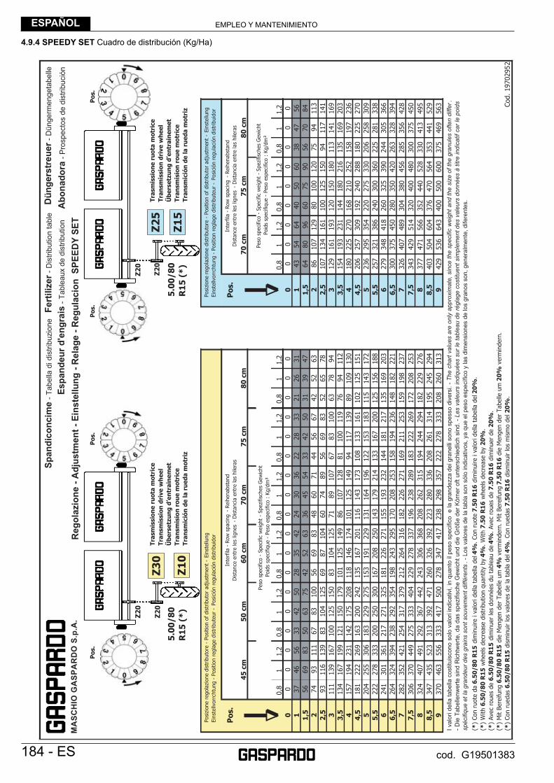
EMPLEO Y MANTENIMIENTOESPAÑOL
184 - ES cod. G19501383
4.9.4 SPEEDY SET Cuadro de distribución (Kg/Ha)
M
AS
CH
IO G
AS
PA
RD
O S
.p.A
.

EMPLEO Y MANTENIMIENTO ESPAÑOL
ES - 185cod. G19501383
4.9.5 MICROGRANULADORE Cuadro de distribución (Kg/Ha)
MA
SC
HIO
GA
SP
AR
DO
S.p
.A.
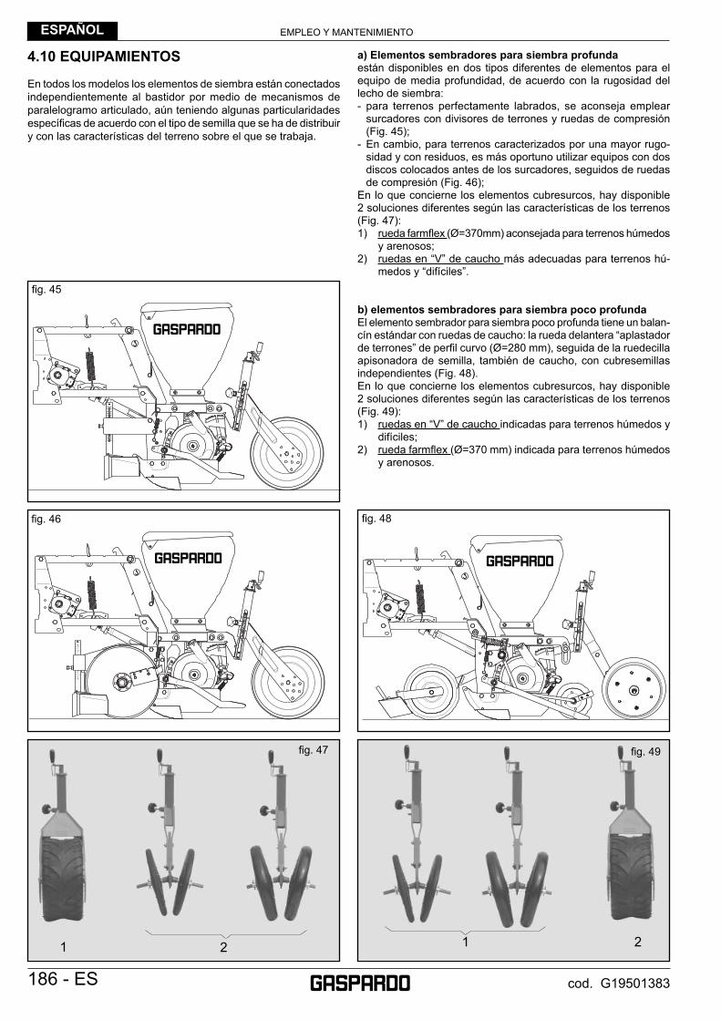
EMPLEO Y MANTENIMIENTOESPAÑOL
186 - ES cod. G19501383
4.10 EQUIPAMIENTOS
En todos los modelos los elementos de siembra están conectados independientemente al bastidor por medio de mecanismos de paralelogramo articulado, aún teniendo algunas particularidades específi cas de acuerdo con el tipo de semilla que se ha de distribuir y con las características del terreno sobre el que se trabaja.
a) Elementos sembradores para siembra profundaestán disponibles en dos tipos diferentes de elementos para el equipo de media profundidad, de acuerdo con la rugosidad del lecho de siembra:- para terrenos perfectamente labrados, se aconseja emplear
surcadores con divisores de terrones y ruedas de compresión (Fig. 45);
- En cambio, para terrenos caracterizados por una mayor rugo-sidad y con residuos, es más oportuno utilizar equipos con dos discos colocados antes de los surcadores, seguidos de ruedas de compresión (Fig. 46);
En lo que concierne los elementos cubresurcos, hay disponible 2 soluciones diferentes según las características de los terrenos (Fig. 47):1) rueda farmfl ex (Ø=370mm) aconsejada para terrenos húmedos
y arenosos;2) ruedas en “V” de caucho más adecuadas para terrenos hú-
medos y “difíciles”.
b) elementos sembradores para siembra poco profundaEl elemento sembrador para siembra poco profunda tiene un balan-cín estándar con ruedas de caucho: la rueda delantera “aplastador de terrones” de perfi l curvo (Ø=280 mm), seguida de la ruedecilla apisonadora de semilla, también de caucho, con cubresemillas independientes (Fig. 48).En lo que concierne los elementos cubresurcos, hay disponible 2 soluciones diferentes según las características de los terrenos (Fig. 49):1) ruedas en “V” de caucho indicadas para terrenos húmedos y
difíciles;2) rueda farmfl ex (Ø=370 mm) indicada para terrenos húmedos
y arenosos.
fi g. 47
21 1 2
fi g. 49
fi g. 46
fi g. 45
fi g. 48

EMPLEO Y MANTENIMIENTO ESPAÑOL
ES - 187cod. G19501383
MONTAJE DE LA RUEDA EN «V» DE CAUCHO (fi g. 50)
REGULACIÓN DE LAS RUEDAS TRASERAS DE COMPRESIÓN (fi g. 51)Los equipos traseros de los elementos de siembra son muy importantes para la siembra de calidad.Dichos elementos son determinantes para la profundidad de siembra y para cubrir las semillas después de la colocación.Por consiguiente, se deben regular oportunamente de acuerdo con el tipo de semilla y terreno, modifi cando la posición de las ruedas traseras en sus respectivos soportes, como indicado en el siguiente esquema.
max 10 cm max 7 cm
max 3,5 cm max 5 cm
max 14 cmmax 4,5 cm
max 11 cmmax 6,5 cm
ELEMENTO DE SIEMBRA MAIZ - GIRASOL - SOJA
ELEMENTO DE SIEMBRA REMOLACHA
fi g. 50
fi g. 51/a
fi g. 51/b
fi g. 51/c
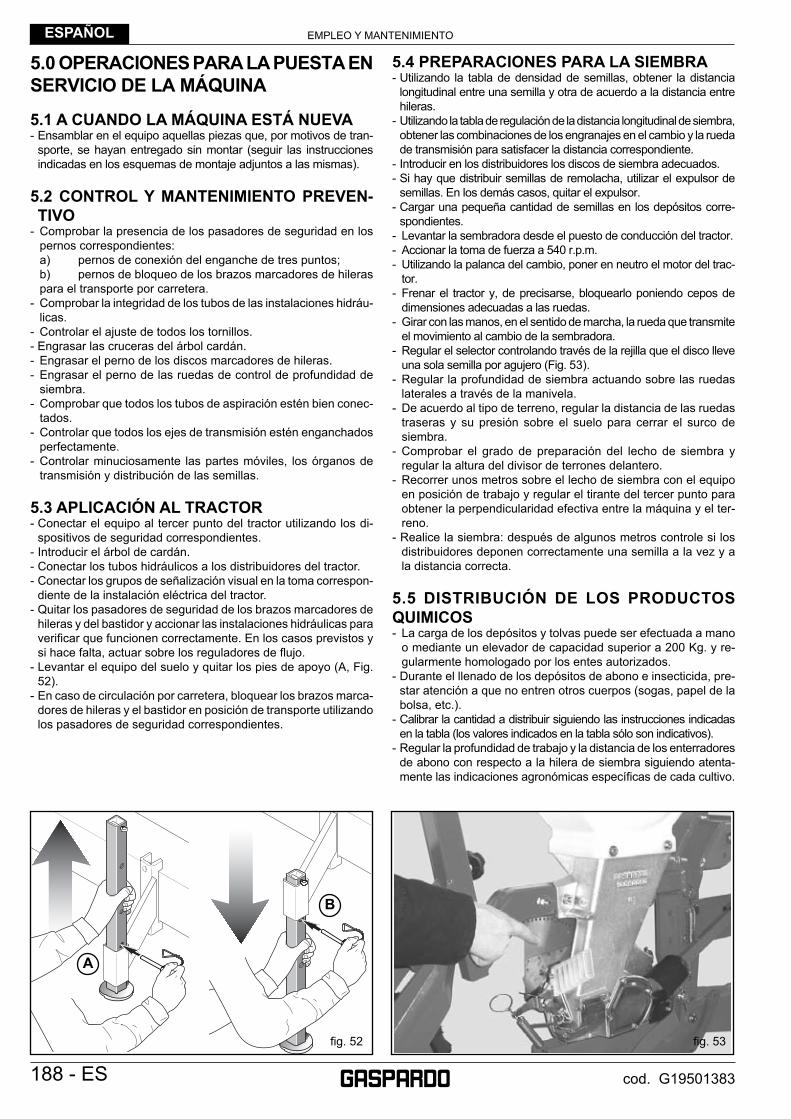
EMPLEO Y MANTENIMIENTOESPAÑOL
188 - ES cod. G19501383
5.0 OPERACIONES PARA LA PUESTA EN SERVICIO DE LA MÁQUINA
5.1 A CUANDO LA MÁQUINA ESTÁ NUEVA- Ensamblar en el equipo aquellas piezas que, por motivos de tran-
sporte, se hayan entregado sin montar (seguir las instrucciones indicadas en los esquemas de montaje adjuntos a las mismas).
5.2 CONTROL Y MANTENIMIENTO PREVEN-TIVO
- Comprobar la presencia de los pasadores de seguridad en los pernos correspondientes:
a) pernos de conexión del enganche de tres puntos; b) pernos de bloqueo de los brazos marcadores de hileras
para el transporte por carretera.- Comprobar la integridad de los tubos de las instalaciones hidráu-
licas.- Controlar el ajuste de todos los tornillos.- Engrasar las cruceras del árbol cardán.- Engrasar el perno de los discos marcadores de hileras.- Engrasar el perno de las ruedas de control de profundidad de
siembra.- Comprobar que todos los tubos de aspiración estén bien conec-
tados.- Controlar que todos los ejes de transmisión estén enganchados
perfectamente.- Controlar minuciosamente las partes móviles, los órganos de
transmisión y distribución de las semillas.
5.3 APLICACIÓN AL TRACTOR- Conectar el equipo al tercer punto del tractor utilizando los di-
spositivos de seguridad correspondientes.- Introducir el árbol de cardán.- Conectar los tubos hidráulicos a los distribuidores del tractor.- Conectar los grupos de señalización visual en la toma correspon-
diente de la instalación eléctrica del tractor.- Quitar los pasadores de seguridad de los brazos marcadores de
hileras y del bastidor y accionar las instalaciones hidráulicas para verifi car que funcionen correctamente. En los casos previstos y si hace falta, actuar sobre los reguladores de fl ujo.
- Levantar el equipo del suelo y quitar los pies de apoyo (A, Fig. 52).
- En caso de circulación por carretera, bloquear los brazos marca-dores de hileras y el bastidor en posición de transporte utilizando los pasadores de seguridad correspondientes.
5.4 PREPARACIONES PARA LA SIEMBRA- Utilizando la tabla de densidad de semillas, obtener la distancia
longitudinal entre una semilla y otra de acuerdo a la distancia entre hileras.
- Utilizando la tabla de regulación de la distancia longitudinal de siembra, obtener las combinaciones de los engranajes en el cambio y la rueda de transmisión para satisfacer la distancia correspondiente.
- Introducir en los distribuidores los discos de siembra adecuados.- Si hay que distribuir semillas de remolacha, utilizar el expulsor de
semillas. En los demás casos, quitar el expulsor.- Cargar una pequeña cantidad de semillas en los depósitos corre-
spondientes.- Levantar la sembradora desde el puesto de conducción del tractor.- Accionar la toma de fuerza a 540 r.p.m.- Utilizando la palanca del cambio, poner en neutro el motor del trac-
tor.- Frenar el tractor y, de precisarse, bloquearlo poniendo cepos de
dimensiones adecuadas a las ruedas.- Girar con las manos, en el sentido de marcha, la rueda que transmite
el movimiento al cambio de la sembradora.- Regular el selector controlando través de la rejilla que el disco lleve
una sola semilla por agujero (Fig. 53).- Regular la profundidad de siembra actuando sobre las ruedas
laterales a través de la manivela.- De acuerdo al tipo de terreno, regular la distancia de las ruedas
traseras y su presión sobre el suelo para cerrar el surco de siembra.
- Comprobar el grado de preparación del lecho de siembra y regular la altura del divisor de terrones delantero.
- Recorrer unos metros sobre el lecho de siembra con el equipo en posición de trabajo y regular el tirante del tercer punto para obtener la perpendicularidad efectiva entre la máquina y el ter-reno.
- Realice la siembra: después de algunos metros controle si los distribuidores deponen correctamente una semilla a la vez y a la distancia correcta.
5.5 DISTRIBUCIÓN DE LOS PRODUCTOS QUIMICOS- La carga de los depósitos y tolvas puede ser efectuada a mano
o mediante un elevador de capacidad superior a 200 Kg. y re-gularmente homologado por los entes autorizados.
- Durante el llenado de los depósitos de abono e insecticida, pre-star atención a que no entren otros cuerpos (sogas, papel de la bolsa, etc.).
- Calibrar la cantidad a distribuir siguiendo las instrucciones indicadas en la tabla (los valores indicados en la tabla sólo son indicativos).
- Regular la profundidad de trabajo y la distancia de los enterradores de abono con respecto a la hilera de siembra siguiendo atenta-mente las indicaciones agronómicas específi cas de cada cultivo.
fi g. 53fi g. 52
B
A
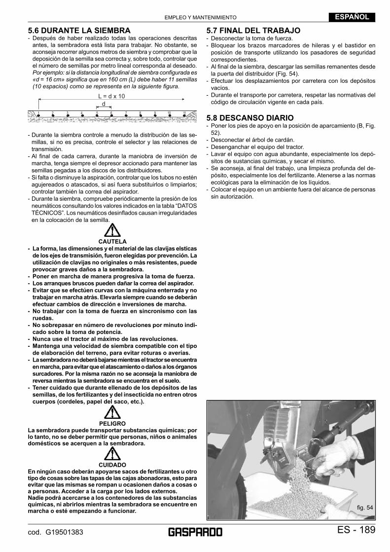
EMPLEO Y MANTENIMIENTO ESPAÑOL
ES - 189cod. G19501383
5.6 DURANTE LA SIEMBRA- Después de haber realizado todas las operaciones descritas
antes, la sembradora está lista para trabajar. No obstante, se aconseja recorrer algunos metros de siembra y comprobar que la deposición de la semilla sea correcta y, sobre todo, controlar que el número de semillas por metro lineal corresponda al deseado. Por ejemplo: si la distancia longitudinal de siembra confi gurada es «d = 16 cm» signifi ca que en 160 cm (L) debe haber 11 semillas (10 espacios) como se representa en la siguiente fi gura.
dL = d x 10
1 2 3 4 5 6 7 8 9 10 11
- Durante la siembra controle a menudo la distribución de las se-millas, si no es precisa, controle el selector y las relaciones de transmisión.
- Al fi nal de cada carrera, durante la maniobra de inversión de marcha, tenga siempre el depresor accionado para mantener las semillas pegadas a los discos de los distribuidores.
- Si falta o disminuye la aspiración, controlar que los tubos no estén agujereados o atascados, si así fuera substituirlos o limpiarlos; controlar también la correa del aspirador.
- Durante la siembra, compruebe periódicamente la presión de los neumáticos consultando los valores indicados en la tabla “DATOS TÉCNICOS”. Los neumáticos desinfl ados causan irregularidades en la colocación de la semilla.
CAUTELA
- La forma, las dimensiones y el material de las clavijas elsticas de los ejes de transmisión, fueron elegidas por prevención. La utilización de clavijas no originales o más resistentes, puede provocar graves daños a la sembradora.
- Poner en marcha de manera progresiva la toma de fuerza. - Los arranques bruscos pueden dañar la correa del aspirador.- Evitar que se efectúen curvas con la máquina enterrada y no
trabajar en marcha atrás. Elevarla siempre cuando se deberán efectuar cambios de dirección e inversiones de marcha.
- No trabajar con la toma de fuerza en sincronismo con las ruedas.
- No sobrepasar en número de revoluciones por minuto indi-cado sobre la toma de potencia.
- Nunca use el tractor al máximo de las revoluciones. - Mantenga una velocidad de siembra compatible con el tipo
de elaboración del terreno, para evitar roturas o averías.- La sembradora no deberá bajarse mientras el tractor se encuentra
en marcha, para evitar que el atascamiento o daños a los órganos surcadores. Por la misma razón no se aconseja la maniobra de reversa mientras la sembradora se encuentra en el suelo.
- Tener cuidado que durante ellenado de los depósitos de las semillas, de los fertilizantes y del insecticida no entren otros cuerpos (cordeles, papel del saco, etc.).
PELIGRO
La sembradora puede transportar substancias químicas; por lo tanto, no se deber permitir que personas, niños o animales domésticos se acerquen a la sembradora.
CUIDADO
En ningún caso deberán apoyarse sacos de fertilizantes u otro tipo de cosas sobre las tapas de las cajas abonadoras, esto para evitar que las mismas se rompan u ocasionen daños a cosas o a personas. Acceder a la carga por los lados externos.Nadie podrá acercarse a los contenedores de las substancias químicas, ni abrirlos mientras la sembradora se encuentre en marcha o esté empezando a funcionar.
5.7 FINAL DEL TRABAJO- Desconectar la toma de fuerza.- Bloquear los brazos marcadores de hileras y el bastidor en
posición de transporte utilizando los pasadores de seguridad correspondientes.
- Al fi nal de la siembra, descargar las semillas remanentes desde la puerta del distribuidor (Fig. 54).
- Efectuar los desplazamientos por carretera con los depósitos vacíos.
- Durante el transporte por carretera, respetar las normativas del código de circulación vigente en cada país.
5.8 DESCANSO DIARIO- Poner los pies de apoyo en la posición de aparcamiento (B, Fig.
52).- Desconectar el árbol de cardán.- Desenganchar el equipo del tractor.- Lavar el equipo con agua abundante, especialmente los depó-
sitos de sustancias químicas, y secar el mismo.- Se aconseja, al fi nal del trabajo, una limpieza profunda del de-
pósito, especialmente los del fertilizante. Atenerse a las normas ecológicas para la eliminación de los líquidos.
- Colocar el equipo en un ambiente fuera del alcance de personas sin autorización.
fi g. 54
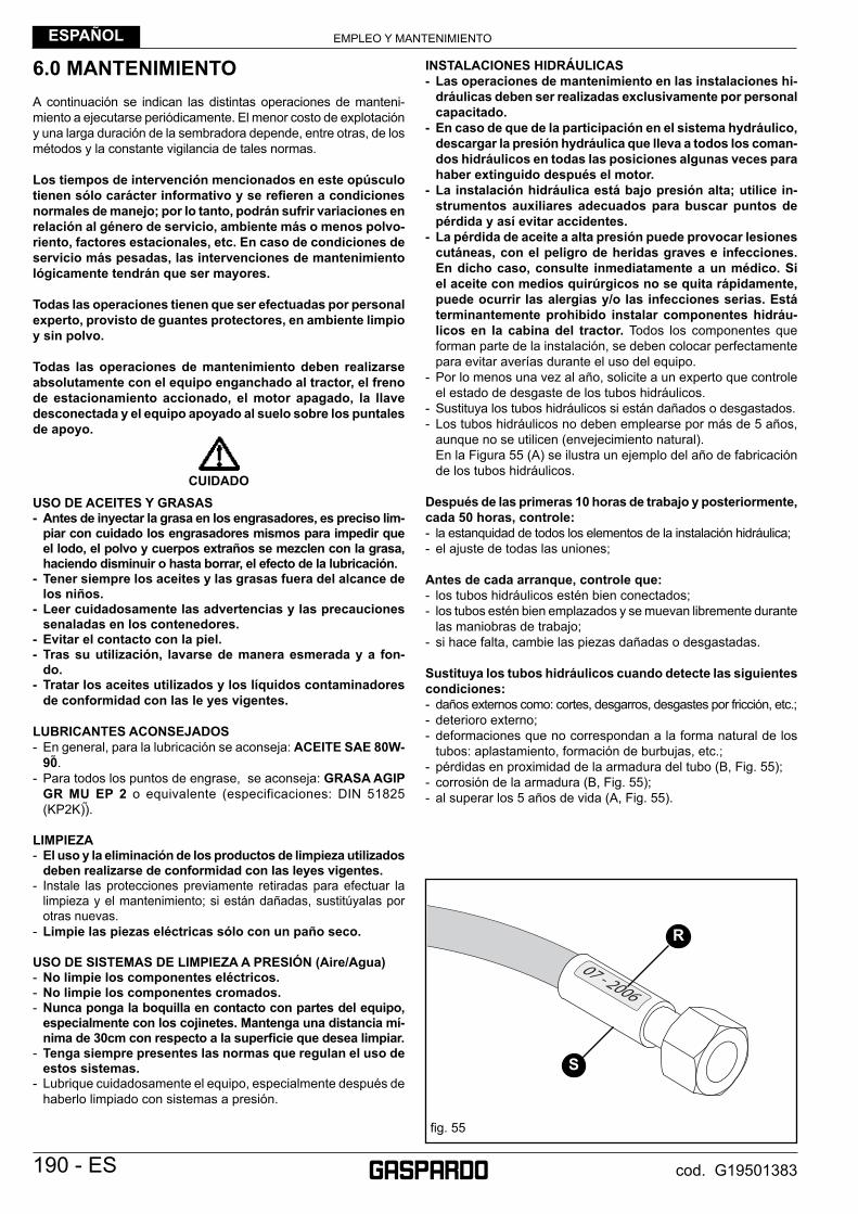
EMPLEO Y MANTENIMIENTOESPAÑOL
190 - ES cod. G19501383
6.0 MANTENIMIENTOA continuación se indican las distintas operaciones de manteni-miento a ejecutarse periódicamente. El menor costo de explotación y una larga duración de la sembradora depende, entre otras, de los métodos y la constante vigilancia de tales normas.
Los tiempos de intervención mencionados en este opúsculo tienen sólo carácter informativo y se refi eren a condiciones normales de manejo; por lo tanto, podrán sufrir variaciones en relación al género de servicio, ambiente más o menos polvo-riento, factores estacionales, etc. En caso de condiciones de servicio más pesadas, las intervenciones de mantenimiento lógicamente tendrán que ser mayores.
Todas las operaciones tienen que ser efectuadas por personal experto, provisto de guantes protectores, en ambiente limpio y sin polvo.
Todas las operaciones de mantenimiento deben realizarse absolutamente con el equipo enganchado al tractor, el freno de estacionamiento accionado, el motor apagado, la llave desconectada y el equipo apoyado al suelo sobre los puntales de apoyo.
CUIDADOUSO DE ACEITES Y GRASAS- Antes de inyectar la grasa en los engrasadores, es preciso lim-
piar con cuidado los engrasadores mismos para impedir que el lodo, el polvo y cuerpos extraños se mezclen con la grasa, haciendo disminuir o hasta borrar, el efecto de la lubricación.
- Tener siempre los aceites y las grasas fuera del alcance de los niños.
- Leer cuidadosamente las advertencias y las precauciones senaladas en los contenedores.
- Evitar el contacto con la piel.- Tras su utilización, lavarse de manera esmerada y a fon-
do.- Tratar los aceites utilizados y los líquidos contaminadores
de conformidad con las le yes vigentes.
LUBRICANTES ACONSEJADOS- En general, para la lubricación se aconseja: ACEITE SAE 80W-
90 .- Para todos los puntos de engrase, se aconseja: GRASA AGIP
GR MU EP 2 o equivalente (especificaciones: DIN 51825 (KP2K)) .
LIMPIEZA- El uso y la eliminación de los productos de limpieza utilizados
deben realizarse de conformidad con las leyes vigentes.- Instale las protecciones previamente retiradas para efectuar la
limpieza y el mantenimiento; si están dañadas, sustitúyalas por otras nuevas.
- Limpie las piezas eléctricas sólo con un paño seco.
USO DE SISTEMAS DE LIMPIEZA A PRESIÓN (Aire/Agua) - No limpie los componentes eléctricos.- No limpie los componentes cromados.- Nunca ponga la boquilla en contacto con partes del equipo,
especialmente con los cojinetes. Mantenga una distancia mí-nima de 30cm con respecto a la superfi cie que desea limpiar.
- Tenga siempre presentes las normas que regulan el uso de estos sistemas.
- Lubrique cuidadosamente el equipo, especialmente después de haberlo limpiado con sistemas a presión.
INSTALACIONES HIDRÁULICAS - Las operaciones de mantenimiento en las instalaciones hi-
dráulicas deben ser realizadas exclusivamente por personal capacitado.
- En caso de que de la participación en el sistema hydráulico, descargar la presión hydráulica que lleva a todos los coman-dos hidráulicos en todas las posiciones algunas veces para haber extinguido después el motor.
- La instalación hidráulica está bajo presión alta; utilice in-strumentos auxiliares adecuados para buscar puntos de pérdida y así evitar accidentes.
- La pérdida de aceite a alta presión puede provocar lesiones cutáneas, con el peligro de heridas graves e infecciones. En dicho caso, consulte inmediatamente a un médico. Si el aceite con medios quirúrgicos no se quita rápidamente, puede ocurrir las alergias y/o las infecciones serias. Está terminantemente prohibido instalar componentes hidráu-licos en la cabina del tractor. Todos los componentes que forman parte de la instalación, se deben colocar perfectamente para evitar averías durante el uso del equipo.
- Por lo menos una vez al año, solicite a un experto que controle el estado de desgaste de los tubos hidráulicos.
- Sustituya los tubos hidráulicos si están dañados o desgastados.- Los tubos hidráulicos no deben emplearse por más de 5 años,
aunque no se utilicen (envejecimiento natural). En la Figura 55 (A) se ilustra un ejemplo del año de fabricación
de los tubos hidráulicos.
Después de las primeras 10 horas de trabajo y posteriormente, cada 50 horas, controle:- la estanquidad de todos los elementos de la instalación hidráulica;- el ajuste de todas las uniones;
Antes de cada arranque, controle que:- los tubos hidráulicos estén bien conectados;- los tubos estén bien emplazados y se muevan libremente durante
las maniobras de trabajo;- si hace falta, cambie las piezas dañadas o desgastadas.
Sustituya los tubos hidráulicos cuando detecte las siguientes condiciones:- daños externos como: cortes, desgarros, desgastes por fricción, etc.;- deterioro externo;- deformaciones que no correspondan a la forma natural de los
tubos: aplastamiento, formación de burbujas, etc.;- pérdidas en proximidad de la armadura del tubo (B, Fig. 55);- corrosión de la armadura (B, Fig. 55);- al superar los 5 años de vida (A, Fig. 55).
fi g. 55
R
S
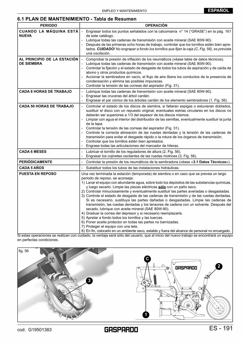
EMPLEO Y MANTENIMIENTO ESPAÑOL
ES - 191cod. G19501383
6.1 PLAN DE MANTENIMIENTO - Tabla de ResumenPERIODO OPERACIÓN
CUANDO LA MÁQUINA ESTÁ NUEVA
- Engrasar todos los puntos señalados con la calcomanía n° 14 (“GRASE”) en la pág. 161 de este catálogo.
- Lubrique todas las cadenas de transmisión con aceite mineral (SAE 80W-90).- Después de las primeras ocho horas de trabajo, controlar que los tornillos estén bien apre-
tados. CUIDADO! No engrapar a fondo los tornillos que fi jan la caja (C, Fig. 56), es prevista una oscilación..
AL PRINCIPIO DE LA ESTACIÓN DE SIEMBRA
- Comprobar la presión de infl ación de los neumáticos (véase tabla de datos técnicos).- Lubrique todas las cadenas de transmisión con aceite mineral (SAE 80W-90).- Controlar la fi jación y el estado de desgaste de todos los tubos de aspiración y de caída de
abono y otros productos químicos.- Accionar la sembradora en vacío, el fl ujo de aire libera los conductos de la presencia de
condensación y elimina las posibles impurezas.- Controlar la tensión de las correas del aspirador (Fig. 31).
CADA 8 HORAS DE TRABAJO - Lubrique todas las cadenas de transmisión con aceite mineral (SAE 80W-90).- Engrasar las cruceras del árbol cardán.- Engrasar el par cónico de los árboles cardán de los elemento sembradores (1, Fig. 56).
CADA 50 HORAS DE TRABAJO - Controlar el estado de los discos de siembra, si faltaran espigas o estuvieran doblados, sustituir el disco con un repuesto original; eventuales estrias circulares en los discos no deberán ser superiores a 1/3 del espesor de los discos mismos.
- Limpiar con agua el interior del distribuidor de las semillas, eventualmente sustituir la junta de la tapa.
- Controlar la tensión de las correas del aspirador (Fig. 31).- Controle la correcta alineación de las ruedas dentadas y la tensión de las cadenas de
transmisión para evitar el desgaste rápido o la rotura de los órganos de transmisión.- Controlar que los tornillos estén bien apretados.- Engrase todas las articulaciones del marcador de hileras.
CADA 6 MESES - Lubricar el tornillo de los reguladores de altura (2, Fig. 56).- Engrasar los cojinetes oscilantes de las ruedas motrices (3, Fig. 56).
PERIÓDICAMENTE - Controlar la presión de los neumáticos de la sembradora (véase «3.1 Datos Técnicos»).CADA 5 AÑOS - Substituir todos los tubos de las instalaciones hidráulicas. PUESTA EN REPOSO Una vez terminada la estación (temporada) de siembra o en caso que se prevea un largo
periodo de reposo, se aconseja:1) Lavar el equipo con abundante agua, sobre todo los depósitos de las substancias químicas,
y luego secarlo. Limpie las piezas eléctricas sólo con un paño seco.2) Controlar minuciosamente y eventualmente sustituir las partes averiadas o desgastadas.3) Controle el estado de desgaste de las cadenas de transmisión y de las ruedas dentadas.
Si es necesario, sustituya las partes dañadas o desgastadas. Limpie las cadenas de transmisión, las ruedas dentadas y los tensores de cadena con un solvente. Después del secado, lubrique con aceite mineral (SAE 80W-90).
4) Graduar la correa del depresor y si necesario reemplazarla.5) Apretar a fondo todos los tornillos y las tuercas.6) Poner aceite protector en todas las partes no barnizadas.7) Proteger el equipo con una tela.8) En fi n, colocarlo en un ambiente seco, estable y fuera del alcance de personal no encargado.
Si estas operaciones se realizan con cuidado, la ventaja será sólo del usuario, que al inicio del nuevo trabajo se encontrará un equipo en perfectas condiciones.
3
C2
1
fi g. 56
EMPLEO Y MANTENIMIENTOESPAÑOL
192 - ES cod. G19501383
6.2 INCONVENIENTES, CAUSAS Y SOLUCIONES
PROBLEMAS CAUSAS SOLUCIONES
Siembra irregular(distancia imprecisa entre las semillas).
1) Desgaste del surcador.2) Muelle tensor demasiado tensado.3) Ruedas cubresemillas traseras no adecuadas.4) Disco de siembra deformado o desgastado (más
de1/3 del grosor original).
5) Púas del disco de siembra deformadas o ausen-tes.
6) Junta del disco siembra desgastada o rota.7) Selector móvil mal regulado. ¡ATENCIÓN! El
selector no regula la entrada de la cantidad de aire al distribuidor de semillas.
8) Neumáticos desinfl ados: relación de transmisión alterada.
9) Velocidad de avance excesiva.10) Relación RUEDA-EJE DE CAMBIO y/o regula-
ción del cambio incorrectas.11) Caída de revoluciones del aspirador.
12) Desgaste de las articulaciones del árbol de tran-smisión del distribuidor.
13) Utilización de semillas pequeñas o con carga electrostática (colza, remolacha).
14) La sembradora no está perpendicular al terreno, sino con la punta hacia delante.
15) Los discos surcadores se llenan de tierra porque están inclinados hacia atrás.
16) Los discos surcadores no giran.
17) Juego sobre los casquillo.
1) Sustituir.2) Afl ojar.3) Sustituir.4) Sustituir el disco de siembra. Al sustituir el disco
de siembra se recomienda sustituir también la junta.
5) Sustituir el disco de siembra.
6) Sustituir la junta.7) Regular el selector: Semillas pequeñas (n.º pequeño en el selector). Semillas grandes (n.º grande en el selector).8) Infl ar según se indica en la tabla de datos técni-
cos.9) Reducir la velocidad de siembra.10) Consultar la tabla RUEDA-CAMBIO y cambiar
las relaciones según corresponda.11) Controlar: a) la tensión de la correa; b) las revoluciones de la toma de fuerza del trac-
tor; c) la ruptura de los tubos de aire en los elementos
sembradores.12) Sustituir.
13) Utilizar el expulsor para semillas en píldoras.14) Alargar la unión del tercer punto.
15) Acortar el tercer punto. Acordarse de bajar la máquina con el tractor en movimiento y nunca dar marcha atrás con la sembradora abajo.
16) Sustituir el cojinete del disco surcador. Terreno excesivamente fangoso, no apto para la sem-bradora.
17) Sustituir.
Derrame de semillas del distribuidor.
Placa antiderrame demasiado abierta. Cerrar o sustituir con G22270133.
Llegan pocas semillas al distribuidor.
Placa antiderrame demasiado cerrada. Abrir.
El disco de siembra no gira o no funciona correc-tamente.
1) Par cónico del distribuidor de semillas bloqueado.2) Par cónico del distribuidor de semillas desgastado
o roto.3) Cubo de arrastre del disco oxidado.4) Semilla abonada con productos pegajosos que
aumentan la fricción entre disco y junta.5) Clavija de seguridad de plástico rota.6) Selector móvil demasiado cerrado.7) Utilización del selector fi jo con semillas grandes
(frijoles, garbanzos, etc.)8) Selector fi jo doblado y chocando con el disco.9) Caja de transmisión desgastada o rota.10) Cardán de transmisión del distribuidor desengan-
chado.
1) Desbloquear con productos contra el agarrotamiento.2) Sustituir (sustituir los casquillos y el eje del
engranaje).3) Desbloquear con productos contra el agarrota-
miento.4) Limpiar frecuentemente el disco y la junta. Si es
posible, utilizar otros productos para el abono.5) Sustituir.6) Abrir.7) Retirar el selector fi jo.
8) Sustituir.9) Sustituir.10) Enganchar.
La semilla se cae del disco de siembra.
1) Aspiración insufi ciente a) Correa fl oja. b) Correa rota. c) Tubos de aire perforados. d) Tubos de aire obstruidos.
2) Régimen de revoluciones inconstante o insufi ciente.3) Diámetro insufi ciente de los agujeros de los discos
de siembra.
1) a) Tensar la correa b) Sustituir. c) Sustituir. d) Limpiar (controlar la aspiración en el tubo con
la palma de la mano por el lado del distribuidor de semillas).
2) Usar el acelerador manual del tractor.3) Sustituir los discos de siembra.
El surco de siembra queda abierto y con las semillas descubiertas.
1) Las ruedas de compresión posteriores no se aline-an con el sillion abierto del falcione y el balancín procede inclinado con relación a la dirección d’ desarrollo.
2) Ruedas cubresemillas traseras inadecuadas para el terreno.
1) Registrar la posición del balancín regulando la posición del forcellina previo.
2) Sustituir.
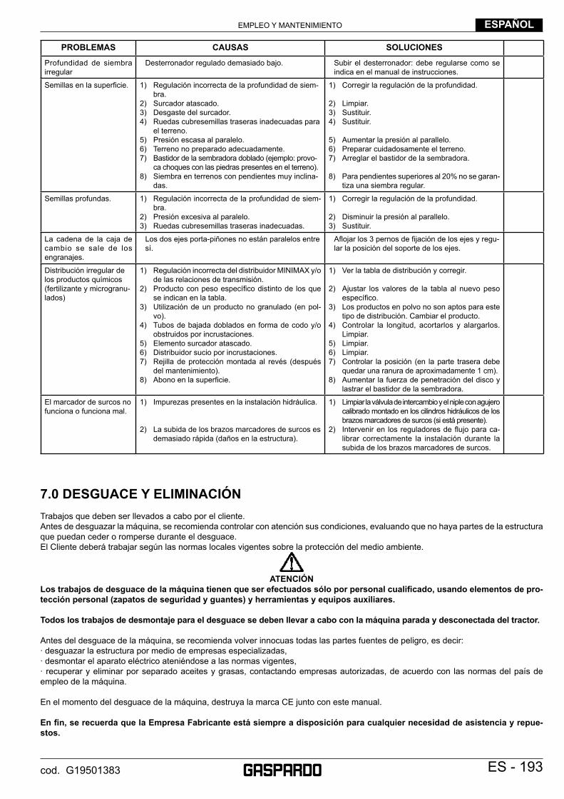
EMPLEO Y MANTENIMIENTO ESPAÑOL
ES - 193cod. G19501383
PROBLEMAS CAUSAS SOLUCIONES
Profundidad de siembra irregular
Desterronador regulado demasiado bajo. Subir el desterronador: debe regularse como se indica en el manual de instrucciones.
Semillas en la superfi cie. 1) Regulación incorrecta de la profundidad de siem-bra.
2) Surcador atascado.3) Desgaste del surcador.4) Ruedas cubresemillas traseras inadecuadas para
el terreno.5) Presión escasa al paralelo.6) Terreno no preparado adecuadamente.7) Bastidor de la sembradora doblado (ejemplo: provo-
ca choques con las piedras presentes en el terreno).8) Siembra en terrenos con pendientes muy inclina-
das.
1) Corregir la regulación de la profundidad.
2) Limpiar.3) Sustituir.4) Sustituir.
5) Aumentar la presión al parallelo.6) Preparar cuidadosamente el terreno.7) Arreglar el bastidor de la sembradora.
8) Para pendientes superiores al 20% no se garan-tiza una siembra regular.
Semillas profundas. 1) Regulación incorrecta de la profundidad de siem-bra.
2) Presión excesiva al paralelo.3) Ruedas cubresemillas traseras inadecuadas.
1) Corregir la regulación de la profundidad.
2) Disminuir la presión al parallelo.3) Sustituir.
La cadena de la caja de cambio se sale de los engranajes.
Los dos ejes porta-piñones no están paralelos entre sí.
Afl ojar los 3 pernos de fi jación de los ejes y regu-lar la posición del soporte de los ejes.
Distribución irregular de los productos químicos(fertilizante y microgranu-lados)
1) Regulación incorrecta del distribuidor MINIMAX y/o de las relaciones de transmisión.
2) Producto con peso específi co distinto de los que se indican en la tabla.
3) Utilización de un producto no granulado (en pol-vo).
4) Tubos de bajada doblados en forma de codo y/o obstruidos por incrustaciones.
5) Elemento surcador atascado.6) Distribuidor sucio por incrustaciones.7) Rejilla de protección montada al revés (después
del mantenimiento).8) Abono en la superfi cie.
1) Ver la tabla de distribución y corregir.
2) Ajustar los valores de la tabla al nuevo peso específi co.
3) Los productos en polvo no son aptos para este tipo de distribución. Cambiar el producto.
4) Controlar la longitud, acortarlos y alargarlos. Limpiar.
5) Limpiar.6) Limpiar.7) Controlar la posición (en la parte trasera debe
quedar una ranura de aproximadamente 1 cm).8) Aumentar la fuerza de penetración del disco y
lastrar el bastidor de la sembradora.
El marcador de surcos no funciona o funciona mal.
1) Impurezas presentes en la instalación hidráulica.
2) La subida de los brazos marcadores de surcos es demasiado rápida (daños en la estructura).
1) Limpiar la válvula de intercambio y el niple con agujero calibrado montado en los cilindros hidráulicos de los brazos marcadores de surcos (si está presente).
2) Intervenir en los reguladores de fl ujo para ca-librar correctamente la instalación durante la subida de los brazos marcadores de surcos.
7.0 DESGUACE Y ELIMINACIÓNTrabajos que deben ser llevados a cabo por el cliente.Antes de desguazar la máquina, se recomienda controlar con atención sus condiciones, evaluando que no haya partes de la estructura que puedan ceder o romperse durante el desguace.El Cliente deberá trabajar según las normas locales vigentes sobre la protección del medio ambiente.
ATENCIÓN
Los trabajos de desguace de la máquina tienen que ser efectuados sólo por personal cualifi cado, usando elementos de pro-tección personal (zapatos de seguridad y guantes) y herramientas y equipos auxiliares.
Todos los trabajos de desmontaje para el desguace se deben llevar a cabo con la máquina parada y desconectada del tractor.
Antes del desguace de la máquina, se recomienda volver innocuas todas las partes fuentes de peligro, es decir:· desguazar la estructura por medio de empresas especializadas,· desmontar el aparato eléctrico ateniéndose a las normas vigentes,· recuperar y eliminar por separado aceites y grasas, contactando empresas autorizadas, de acuerdo con las normas del país de empleo de la máquina.
En el momento del desguace de la máquina, destruya la marca CE junto con este manual.
En fi n, se recuerda que la Empresa Fabricante está siempre a disposición para cualquier necesidad de asistencia y repue-stos.
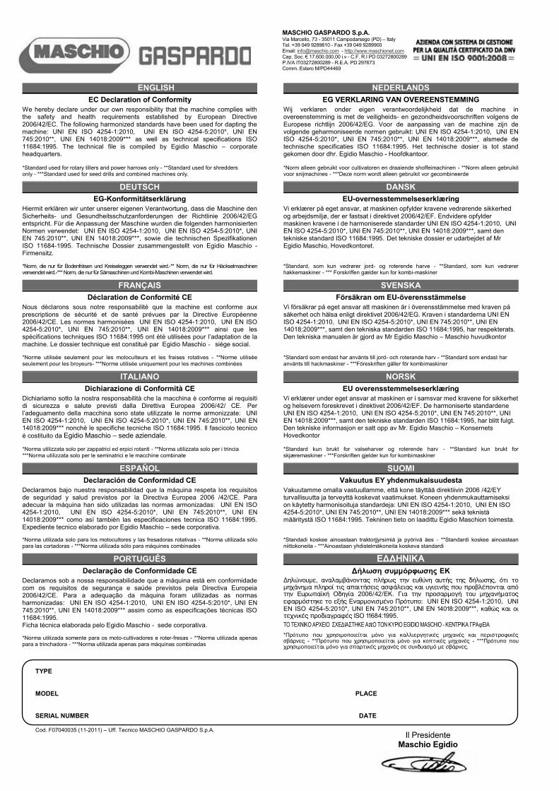
17.600.000
TYPE MODEL PLACE SERIAL NUMBER DATE Cod. F07040035 (11-2011) – Uff. Tecnico MASCHIO GASPARDO S.p.A.
ENGLISH NEDERLANDS EC Declaration of Conformity EG VERKLARING VAN OVEREENSTEMMING
We hereby declare under our own responsibility that the machine complies with the safety and health requirements established by European Directive 2006/42/EC. The following harmonized standards have been used for dapting the machine: UNI EN ISO 4254-1:2010, UNI EN ISO 4254-5:2010*, UNI EN 745:2010**, UNI EN 14018:2009*** as well as technical specifications ISO 11684:1995. The technical file is compiled by Egidio Maschio – corporate headquarters.
Wij verklaren onder eigen verantwoordelijkheid dat de machine in overeenstemming is met de veiligheids- en gezondheidsvoorschriften volgens de Europese richtlijn 2006/42/EG. Voor de aanpassing van de machine zijn de volgende geharmoniseerde normen gebruikt: UNI EN ISO 4254-1:2010, UNI EN ISO 4254-5:2010*, UNI EN 745:2010**, UNI EN 14018:2009***, alsmede de technische specificaties ISO 11684:1995. Het technische dosier is tot stand gekomen door dhr. Egidio Maschio - Hoofdkantoor.
*Standard used for rotary tillers and power harrows only - **Standard used for shredders only - ***Standard used for seed drills and combined machines only. *Norm alleen gebruikt voor cultivatoren en draaiende shoffeimachinen - **Norm alleen gebruikit
voor snijmachines - ***Deze norm wordt alleen gebruikit vor gecombineerde
DEUTSCH DANSK EG-Konformitätserklärung EU-overnesstemmelseserklæring
Hiermit erklären wir unter unserer eigenen Verantwortung, dass die Maschine den Sicherheits- und Gesundheitsschutzanforderungen der Richtlinie 2006/42/EG entspricht. Für die Anpassung der Maschine wurden die folgenden harmonisierten Normen verwendet: UNI EN ISO 4254-1:2010, UNI EN ISO 4254-5:2010*, UNI EN 745:2010**, UNI EN 14018:2009***, sowie die technischen Spezifikationen ISO 11684-1995. Technische Dossier zusammengestellt von Egidio Maschio - Firmensitz.
Vi erklærer på eget ansvar, at maskinen opfylder kravene vedrørende sikkerhed og arbejdsmiljø, der er fastsat i direktivet 2006/42/EF. Endvidere opfylder maskinen kravene i de harmoniserede standarder UNI EN ISO 4254-1:2010, UNI EN ISO 4254-5:2010*, UNI EN 745:2010**, UNI EN 14018:2009***, samt den tekniske standard ISO 11684:1995. Det tekniske dossier er udarbejdet af Mr Egidio Maschio, Hovedkontoret.
*Norm, die nur für Bodenfräsen und Kreiseleggen verwendet wird.-** Norm, die nur für Häckselmaschinen verwendet wird.-*** Norm, die nur für Sämaschinen und Kombi-Maschinen verwendet wird. *Standard, som kun vedrører jord- og roterende harve - **Standard, som kun vedrører
hakkemaskiner - *** Forskriffen gælder kun for kombi-maskiner
FRANÇAIS SVENSKA Déclaration de Conformité CE Försäkran om EU-överensstämmelse
Nous déclarons sous notre responsabilité que la machine est conforme aux prescriptions de sécurité et de santé prévues par la Directive Européenne 2006/42/CE. Les normes harmonisées UNI EN ISO 4254-1:2010, UNI EN ISO 4254-5:2010*, UNI EN 745:2010**, UNI EN 14018:2009*** ainsi que les spécifications techniques ISO 11684:1995 ont été utilisées pour l’adaptation de la machine. Le dossier technique est constituè par Egidio Maschio - siège social.
Vi försäkrar på eget ansvar att maskinen är i överensstämmelse med kraven på säkerhet och hälsa enligt direktivet 2006/42/EG. Kraven i standarderna UNI EN ISO 4254-1:2010, UNI EN ISO 4254-5:2010*, UNI EN 745:2010**, UNI EN 14018:2009***, samt den tekniska standarden ISO 11684:1995, har respekterats. Den tekniska manualen är gjord av Mr Egidio Maschio – Maschio huvudkontor
*Norme utilisée seulement pour les motoculteurs et les fraises rotatives - **Norme utilisée seulement pour les broyeurs- ***Norme utilisée uniquement pour les machines combinées *Standard som endast har använts till jord- och roterande harv - **Standard som endast har
använts till hackmaskiner - ***Föreskriften gäller för kombimaskiner ITALIANO NORSK
Dichiarazione di Conformità CE EU overensstemmelseserklæring Dichiariamo sotto la nostra responsabilità che la macchina è conforme ai requisiti di sicurezza e salute previsti dalla Direttiva Europea 2006/42/ CE. Per l’adeguamento della macchina sono state utilizzate le norme armonizzate: UNI EN ISO 4254-1:2010, UNI EN ISO 4254-5:2010*, UNI EN 745:2010**, UNI EN 14018:2009*** nonchè le specifiche tecniche ISO 11684:1995. Il fascicolo tecnico è costituito da Egidio Maschio – sede aziendale.
Vi erklærer under eget ansvar at maskinen er i samsvar med kravene for sikkerhet og helsevern foreskrevet i direktivet 2006/42/EF. De harmoniserte standardene UNI EN ISO 4254-1:2010, UNI EN ISO 4254-5:2010*, UNI EN 745:2010**, UNI EN 14018:2009***, samt den tekniske standarden ISO 11684:1995, har blitt fulgt. Den tekniske informasjon er satt opp av Mr. Egidio Maschio – Konsernets Hovedkontor
*Norma utilizzata solo per zappatrici ed erpici rotanti - **Norma utilizzata solo per i trincia ***Norma utilizzata solo per le seminatrici e le macchine combinate *Standard kun brukt for valseharver og roterende harv - **Standard kun brukt for
skjæremaskiner - ***Forskriften gjelder kun for kombimaskiner
ESPAÑOL SUOMI Declaración de Conformidad CE Vakuutus EY yhdenmukaisuudesta
Declaramos bajo nuestra responsabilidad que la máquina respeta los requisitos de seguridad y salud previstos por la Directiva Europea 2006 /42/CE. Para adecuar la máquina han sido utilizadas las normas armonizadas: UNI EN ISO 4254-1:2010, UNI EN ISO 4254-5:2010*, UNI EN 745:2010**, UNI EN 14018:2009*** como así también las especificaciones tecnica ISO 11684:1995. Expediente tecnico elaborado por Egidio Maschio – sede corporativa.
Vakuutamme omalla vastuullamme, että kone täyttää direktiivin 2006 /42/EY turvallisuutta ja terveyttä koskevat vaatimukset. Koneen yhdenmukauttamiseksi on käytetty harmonisoituja standardeja: UNI EN ISO 4254-1:2010, UNI EN ISO 4254-5:2010*, UNI EN 745:2010**, UNI EN 14018:2009*** sekä teknistä määritystä ISO 11684:1995. Tekninen tieto on laadittu Egidio Maschion toimesta.
*Norma utilizada solo para los motocultores y las fresadoras rotativas - **Norma utilizada sólo para las cortadoras - ***Norma utilizada sólo para máquines combinades *Standadi koskee ainoastaan traktorjjyrsimiä ja pyörivä äes - **Standardi koskee ainoastaan
niittokoneita - ***Ainoastaan yhdistelmäkoneita koskeva standardi
PORTUGUÊS EÄÄHNIKA Declaração de Conformidade CE Äήλωση συμμόρφωσης ΕΚ
Declaramos sob a nossa responsabilidade que a máquina está em conformidade com os requisitos de segurança e saúde previstos pela Directiva Europeia 2006/42/CE. Para a adequação da máquina foram utilizadas as normas harmonizadas: UNI EN ISO 4254-1:2010, UNI EN ISO 4254-5:2010*, UNI EN 745:2010**, UNI EN 14018:2009*** assim como as especificações técnicas ISO 11684:1995. Ficha técnica elaborada pelo Egidio Maschio - sede corporativa.
Äçëþíïõìå, áíáëáìâÜíïíôáò ðëÞñùò ôçí åõèýíç áõôÞò ôçò äÞëùóçò, üôé ôï ìç÷Üíçìá ðëçñïß ôéò áðáéôÞóåéò áóöÜëåéáò êáé õãéåéíÞò ðïõ ðñïâëÝðïíôáé áðü ôçí ÅõñùðáúêÞ Ïäçãßá 2006/42/ÅÊ. Ãéá ôçí ðñïóáñìïãÞ ôïõ ìç÷áíÞìáôïò åöáñìüóôçêå ôï åîÞò ÅíáñìïíéóìÝíï Ðñüôõðï: UNI EN ISO 4254-1:2010, UNI EN ISO 4254-5:2010*, UNI EN 745:2010**, UNI EN 14018:2009***, êáèþò êáé ïé ôå÷íéêÝò ðñïäéáãñáöÝò ISO 11684:1995.
TO TEXNIKO APXEIO ÓXEÄIAÓTHKE AπO TON KYPIO EGIDIO MASCHIO - KENTPIKA ÃPAöEIA *Norma utilizada somente para os moto-cultivadores e roter-fresas - **Norma utilizada apenas para a trinchadora - ***Norma utilizada apenas para máquinas combinadas
*Ðñüôõðï ðïõ ÷ñçóéìïðïéåßôáé ìüíï ãéá êáëëéåñãçôéêÝò ìç÷áíÝò êáé ðåñéóôñïöéêÝò óâÜñíåò - **Ðñüôõðï ðïõ ÷ñçóéìïðïéåßôáé ìüíï ãéá êïðôéêÝò ìç÷áíÝò - ***Ðñüôõðï ðïõ ÷ñçóéìïðïéåßôáé ìüíï ãéá óðáñôéêÝò ìç÷áíÝò óå óõíäõáóìü ìå óâÜñíåò.
MASCHIO GASPARDO S.p.A. Via Marcello, 73 - 35011 Campodarsego (PD) – Italy Tel. +39 049 9289810 - Fax +39 049 9289900 Email: [email protected] - http://www.maschionet.com Cap. Soc. € 17.600.000,00 i.v - C.F. R.I PD 03272800289 P.IVA IT03272800289 - R.E.A. PD 297673 Comm. Estero M/PD44469
Il Presidente Maschio Egidio
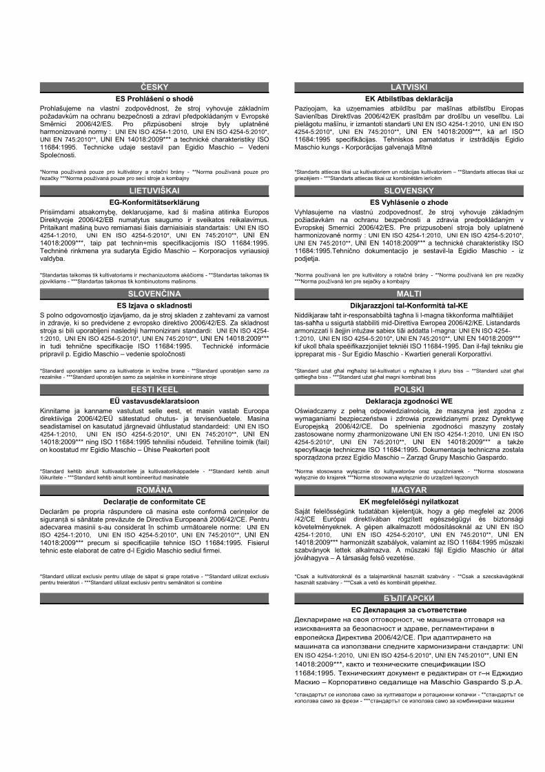
ČESKY LATVISKI ES Prohlášení o shodě EK Atbilstības deklarācija
Prohlašujeme na vlastní zodpovědnost, že stroj vyhovuje základním požadavkům na ochranu bezpečnosti a zdraví předpokládaným v Evropské Směrnici 2006/42/ES. Pro přizpůsobení stroje byly uplatněné harmonizované normy : UNI EN ISO 4254-1:2010, UNI EN ISO 4254-5:2010*, UNI EN 745:2010**, UNI EN 14018:2009*** a technické charakteristiky ISO 11684:1995. Technicke udaje sestavil pan Egidio Maschio – Vedeni SpoleČnosti.
Paziņojam, ka uzņemamies atbildību par mašīnas atbilstību Eiropas Savienības Direktīvas 2006/42/EK prasībām par drošību un veselību. Lai pielāgotu mašīnu, ir izmantoti standarti UNI EN ISO 4254-1:2010, UNI EN ISO 4254-5:2010*, UNI EN 745:2010**, UNI EN 14018:2009***, kā arī ISO 11684:1995 specifikācijas. Tehniskos pamatdatus ir izstrādājis Egidio Maschio kungs - Korporācijas galvenajā Mītnē
*Norma používaná pouze pro kultivátory a rotační brány - **Norma používaná pouze pro řezačky ***Norma používaná pouze pro secí stroje a kombajny *Standarts attiecas tikai uz kultivatoriem un rotācijas kultivatoriem – **Standarts attiecas tikai uz
griezējiem - ***Standarts attiecas tikai uz kombinētām ierīcēm
LIETUVIŠKAI SLOVENSKY EG-Konformitätserklärung ES Vyhlásenie o zhode
Prisiimdami atsakomybę, deklaruojame, kad ši mašina atitinka Europos Direktyvoje 2006/42/EB numatytus saugumo ir sveikatos reikalavimus. Pritaikant mašiną buvo remiamasi šiais darniaisiais standartais: UNI EN ISO 4254-1:2010, UNI EN ISO 4254-5:2010*, UNI EN 745:2010**, UNI EN 14018:2009***, taip pat technin÷mis specifikacijomis ISO 11684:1995. Techninė rinkmena yra sudaryta Egidio Maschio – Korporacijos vyriausioji valdyba.
Vyhlasujeme na vlastnú zodpovednosť, že stroj vyhovuje základným požiadavkám na ochranu bezpečnosti a zdravia predpokládaným v Evropskej Smernici 2006/42/ES. Pre prizpusobení stroja boly uplatnené harmonizované normy : UNI EN ISO 4254-1:2010, UNI EN ISO 4254-5:2010*, UNI EN 745:2010**, UNI EN 14018:2009*** a technické charakteristiky ISO 11684:1995.Tehnično dokumentacijo je sestavil-la Egidio Maschio - iz podjetja.
*Standartas taikomas tik kultivatoriams ir mechanizuotoms akėčioms - **Standartas taikomas tik pjovikliams - ***Standartas taikomas tik kombinuotoms mašinoms. *Norma používaná len pre kultivátory a rotačné brány - **Norma používaná len pre rezačky
***Norma používaná len pre sejačky a kombajny
SLOVENČINA MALTI ES Izjava o skladnosti Dikjarazzjoni tal-Konformità tal-KE
S polno odgovornostjo izjavljamo, da je stroj skladen z zahtevami za varnost in zdravje, ki so predvidene z evropsko direktivo 2006/42/ES. Za skladnost stroja si bili uporabljeni naslednji harmonizirani standardi: UNI EN ISO 4254-1:2010, UNI EN ISO 4254-5:2010*, UNI EN 745:2010**, UNI EN 14018:2009*** in tudi tehnične specifikacije ISO 11684:1995. Technické informácie pripravil p. Egidio Maschio – vedenie spoločnosti
Niddikjaraw taħt ir-responsabbiltà tagħna li l-magna tikkonforma malħtiāijiet tas-saħħa u ssigurtà stabbiliti mid-Direttiva Ewropea 2006/42/KE. Listandards armonizzati li āejjin intużaw sabiex tiāi addatta l-magna: UNI EN ISO 4254-1:2010, UNI EN ISO 4254-5:2010*, UNI EN 745:2010**, UNI EN 14018:2009*** kif ukoll bħala speëifikazzjonijiet tekniëi ISO 11684-1995. Dan il-fajl tekniku gie ippreparat mis - Sur Egidio Maschio - Kwartieri generali Korporattivi.
*Standard uporabljen samo za kultivatorje in krožne brane - **Standard uporabljen samo za rezalnike - ***Standard uporabljen samo za sejalnike in kombinirane stroje *Standard użat għal mgħażqi tal-kultivaturi u mgħażaq li jduru biss – **Standard użat għal
qattiegħa biss - ***Standard użat għal magni kombinati biss
EESTI KEEL POLSKI EÜ vastavusdeklaratsioon Deklaracja zgodności WE
Kinnitame ja kanname vastutust selle eest, et masin vastab Euroopa direktiiviga 2006/42/EÜ sätestatud ohutus- ja tervisenõuetele. Masina seadistamisel on kasutatud järgnevaid ühtlustatud standardeid: UNI EN ISO 4254-1:2010, UNI EN ISO 4254-5:2010*, UNI EN 745:2010**, UNI EN 14018:2009*** ning ISO 11684:1995 tehnilisi nõudeid. Tehniline toimik (fail) on koostatud mr Egidio Maschio – Ühise Peakorteri poolt
Oświadczamy z pełną odpowiedzialnością, że maszyna jest zgodna z wymaganiami bezpieczeństwa i zdrowia przewidzianymi przez Dyrektywę Europejską 2006/42/CE. Do spełnienia zgodności maszyny zostały zastosowane normy zharmonizowane UNI EN ISO 4254-1:2010, UNI EN ISO 4254-5:2010*, UNI EN 745:2010**, UNI EN 14018:2009*** a także specyfikacje techniczne ISO 11684:1995. Dokumentacja techniczna zostala sporządzona przez Egidio Maschio – Zarząd Grupy Maschio Gaspardo.
*Standard kehtib ainult kultivaatoritele ja kultivaatorikäppadele - **Standard kehtib ainult lõikuritele - ***Standard kehtib ainult kombineeritud masinatele *Norma stosowana wyłącznie do kultywatorów oraz spulchniarek - **Norma stosowana
wyłącznie do krajarek ***Norma stosowana wyłącznie do urządzeń łączonych
ROMÂNA MAGYAR Declaraţie de conformitate CE EK megfelelőségi nyilatkozat
Declarăm pe propria răspundere că masina este conformă cerin elor de siguran ă si sănătate prevăzute de Directiva Europeană 2006/42/CE. Pentru adecvarea masinii s-au considerat în schimb următoarele norme: UNI EN ISO 4254-1:2010, UNI EN ISO 4254-5:2010*, UNI EN 745:2010**, UNI EN 14018:2009*** precum si specifica iile tehnice ISO 11684:1995. Fisierul tehnic este elaborat de catre d-l Egidio Maschio sediul firmei.
Saját felelősségünk tudatában kijelentjük, hogy a gép megfelel az 2006 /42/CE Európai direktívában rögzített egészségügyi és biztonsági követelményeknek. A gépen alkalmazott módosításoknál az UNI EN ISO 4254-1:2010, UNI EN ISO 4254-5:2010*, UNI EN 745:2010**, UNI EN 14018:2009*** harmonizált szabályok, valamint az ISO 11684:1995 műszaki szabványok lettek alkalmazva. A műszaki fájl Egidio Maschio úr által jóváhagyva – A társaság felső vezetése.
*Standard utilizat exclusiv pentru utilaje de săpat si grape rotative - **Standard utilizat exclusiv pentru treierători - ***Standard utilizat exclusiv pentru semănători si combine *Csak a kultivátoroknál és a talajmaróknál használt szabvány - **Csak a szecskavágóknál
használt szabvány - ***Csak a vető és kombinált gépekhez.
БЪЛГАРСКИ ЕС Декларация за съответствие
Декларираме на своя отговорност, че машината отговаря на изискванията за безопасност и здраве, регламентирани в европейска Директива 2006/42/CE. При адаптирането на машината са използвани следните хармонизирани стандарти: UNI EN ISO 4254-1:2010, UNI EN ISO 4254-5:2010*, UNI EN 745:2010**, UNI EN 14018:2009***, както и техническите спецификации ISO 11684:1995. Техническият документ е редактиран от г–н Еджидио Маскио – Корпоративно седалище на Maschio Gaspardo S.p.A.
*стандартът се използва само за култиватори и ротационни копачки - **стандартът се използва само за фрези - ***стандартът се използва само за комбинирани машини

*G19501383*
USATE SEMPRE RICAMBI ORIGINALIALWAYS USE ORIGINAL SPARE PARTS
IMMER DIE ORIGINAL-ERSATZTEILE VERWENDENEMPLOYEZ TOUJOURS LES PIECES DE RECHANGE ORIGINALES
ВСЕГДА ИСПОЛЬЗУЙТЕ ОРИГИНАЛЬНЫЕ ЗАПЧАСТИ
Servizio Assistenza Tecnica - After Sales ServiceServizio Ricambi - Spare Parts Service
+39 0434 695410
DEALER:
www.maschionet.com
Research & Development MASCHIO GASPARDO S.p.A.
000 МАСКИО-ГАСПАРДО РУССИЯУлица Пушкина, 117 Б404126 ВолжскийВолгоградская областьТел. +7 8443 515152факс. +7 8443 [email protected]
MASCHIO-GASPARDO ROMANIA S.R.L.Strada Înfrátirii, F.N.315100 Chisineu-Cris (Arad) - RomâniaTel. +40 257 307030Fax +40 257 [email protected]
MASCHIO-GASPARDO USA Inc120 North Scott Park RoadEldridge, IA 52748 - USAPh. +1 563 2859937Fax +1 563 [email protected]
MASCHIO IBERICA S.L.MASCHIO-GASPARDO POLANDMASCHIO-GASPARDO UCRAINAGASPARDO-MASCHIO TURCHIAMASCHIO-GASPARDO CINAMASCHIO-GASPARDO INDIAMASCHIO-GASPARDO KOREA
MASCHIO GASPARDO SpAProduction Plant Via Mussons, 7 - 33075Morsano al Tagliamento (PN) - ItalyTel. +39 0434 695410 Fax +39 0434 [email protected]
MASCHIO DEUTSCHLAND GMBHÄußere Nürmberger Straße 5D-91177 Thalmässing - DeutschlandTel. +49 (0) 9173 79000 Fax +49 (0) 9173 [email protected]
MASCHIO FRANCE Sarl1, Rue de Mérignan ZAF - 45240 La Ferte St. AubinFranceTel. +33 (0) 2.38.64.12.12 Fax +33 (0) 2.38.64.66.79 [email protected]
MASCHIO GASPARDO SpARegistered Offi ce and Production PlantVia Marcello, 73 - 35011Campodarsego (Padova) - ItalyTel. +39 049 9289810Fax +39 049 [email protected]