Operating instructions ECSxK Capacitor - Lenze
40
EDBCSXKXXX .ðt< Ä."t<ä Operating Instructions ECS Capacitor module of ECSxK series
Transcript of Operating instructions ECSxK Capacitor - Lenze

EDBCSXKXXX.ðt<
Ä."t<ä
Operating Instructions
ECS
Capacitor module of ECSxK series

This documentation is valid for ECS capacitor modules as of version:
ECS x K xxx x 4 B xxx 1A
Type Hans-Lenze-Straße1D-31855 AerzenMade in GermanyL
Input
Output
Overload
Type
Id.-No.
2/PE DC a-aaa/aaaVbb.b/bb.bA
3/PE AC c-ccc/cccVdd.d/dd.dA 0-fffHz
ee.eA
ttttttttttt
Prod.-No. Ser.-No.
yyyyyyyy zzzzxxxxxxxx
EKZ
A-SW B-SW
H.H
ECSEAxxxC4BXXXXXVA02
h.h
Parameter
WA
RN
ING
Devic
eis
live
up
to18
0s
after
rem
ovin
g
ma
ins
vo
ltage
AT
TE
NT
ION
L´a
ppa
reil
estso
us
ten
sio
n
pe
nd
an
t1
80
sa
prè
sla
co
up
ure
de
late
nsio
nrè
se
au
Fo
rd
eta
iled
info
rma
tio
nre
fer
toth
eIn
str
uctio
nM
an
ua
l1D
74
1
Hans-Lenze-Straße1D-31855 AerzenMade in GermanyL
Input
Output
Overload
Type
Id.-No.
2/PE DC a-aaa/aaaVbb.b/bb.bA
3/PE AC c-ccc/cccVdd.d/dd.dA 0-fffHz
ee.eA
ttttttttttt
Prod.-No. Ser.-No.
yyyyyyyy zzzzxxxxxxxx
EKZ
A-SW B-SW
H.H
ECSEAxxxC4BXXXXXVA02
h.h
Parameter
WA
RN
ING
Devic
eis
live
up
to18
0s
after
rem
ovin
g
ma
ins
vo
ltage
AT
TE
NT
ION
L´a
ppa
reil
estso
us
ten
sio
n
pe
nd
an
t1
80
sa
prè
sla
co
up
ure
de
late
nsio
nrè
se
au
Fo
rd
eta
iled
info
rma
tio
nre
fer
toth
eIn
str
uctio
nM
an
ua
l1D
74
1Design
Hans-Lenze-Straße1D-31855 AerzenMade in GermanyL
Input
Output
Overload
Type
Id.-No.
2/PE DC a-aaa/aaaVbb.b/bb.bA
3/PE AC c-ccc/cccVdd.d/dd.dA 0-fffHz
ee.eA
ttttttttttt
Prod.-No. Ser.-No.
yyyyyyyy zzzzxxxxxxxx
EKZ
A-SW B-SW
H.H
ECSEAxxxC4BXXXXXVA02
h.h
Parameter
WA
RN
ING
Devic
eis
live
up
to18
0s
after
rem
ovin
g
ma
ins
vo
ltage
AT
TE
NT
ION
L´a
ppa
reil
estso
us
ten
sio
n
pe
nd
an
t1
80
sa
prè
sla
co
up
ure
de
late
nsio
nrè
se
au
Fo
rd
eta
iled
info
rma
tio
nre
fer
toth
eIn
str
uctio
nM
an
ua
l1D
74
1E = Enclosure IP20D = Push-through technique (thermally separated)C = Cold plate
Hans-Lenze-Straße1D-31855 AerzenMade in GermanyL
Input
Output
Overload
Type
Id.-No.
2/PE DC a-aaa/aaaVbb.b/bb.bA
3/PE AC c-ccc/cccVdd.d/dd.dA 0-fffHz
ee.eA
ttttttttttt
Prod.-No. Ser.-No.
yyyyyyyy zzzzxxxxxxxx
EKZ
A-SW B-SW
H.H
ECSEAxxxC4BXXXXXVA02
h.h
Parameter
WA
RN
ING
Devic
eis
live
up
to18
0s
after
rem
ovin
g
ma
ins
vo
ltage
AT
TE
NT
ION
L´a
ppa
reil
estso
us
ten
sio
n
pe
nd
an
t1
80
sa
prè
sla
co
up
ure
de
late
nsio
nrè
se
au
Fo
rd
eta
iled
info
rma
tio
nre
fer
toth
eIn
str
uctio
nM
an
ua
l1D
74
1
Hans-Lenze-Straße1D-31855 AerzenMade in GermanyL
Input
Output
Overload
Type
Id.-No.
2/PE DC a-aaa/aaaVbb.b/bb.bA
3/PE AC c-ccc/cccVdd.d/dd.dA 0-fffHz
ee.eA
ttttttttttt
Prod.-No. Ser.-No.
yyyyyyyy zzzzxxxxxxxx
EKZ
A-SW B-SW
H.H
ECSEAxxxC4BXXXXXVA02
h.h
Parameter
WA
RN
ING
Devic
eis
live
up
to18
0s
after
rem
ovin
g
ma
ins
vo
ltage
AT
TE
NT
ION
L´a
ppa
reil
estso
us
ten
sio
n
pe
nd
an
t1
80
sa
prè
sla
co
up
ure
de
late
nsio
nrè
se
au
Fo
rd
eta
iled
info
rma
tio
nre
fer
toth
eIn
str
uctio
nM
an
ua
l1D
74
1
Capacity
Hans-Lenze-Straße1D-31855 AerzenMade in GermanyL
Input
Output
Overload
Type
Id.-No.
2/PE DC a-aaa/aaaVbb.b/bb.bA
3/PE AC c-ccc/cccVdd.d/dd.dA 0-fffHz
ee.eA
ttttttttttt
Prod.-No. Ser.-No.
yyyyyyyy zzzzxxxxxxxx
EKZ
A-SW B-SW
H.H
ECSEAxxxC4BXXXXXVA02
h.h
Parameter
WA
RN
ING
Devic
eis
live
up
to18
0s
after
rem
ovin
g
ma
ins
vo
ltage
AT
TE
NT
ION
L´a
ppa
reil
estso
us
ten
sio
n
pe
nd
an
t1
80
sa
prè
sla
co
up
ure
de
late
nsio
nrè
se
au
Fo
rd
eta
iled
info
rma
tio
nre
fer
toth
eIn
str
uctio
nM
an
ua
l1D
74
1
001 = 705 µF (±20 %)002 = 1410 µF (±20 %)
Hans-Lenze-Straße1D-31855 AerzenMade in GermanyL
Input
Output
Overload
Type
Id.-No.
2/PE DC a-aaa/aaaVbb.b/bb.bA
3/PE AC c-ccc/cccVdd.d/dd.dA 0-fffHz
ee.eA
ttttttttttt
Prod.-No. Ser.-No.
yyyyyyyy zzzzxxxxxxxx
EKZ
A-SW B-SW
H.H
ECSEAxxxC4BXXXXXVA02
h.h
Parameter
WA
RN
ING
Devic
eis
live
up
to18
0s
after
rem
ovin
g
ma
ins
vo
ltage
AT
TE
NT
ION
L´a
ppa
reil
estso
us
ten
sio
n
pe
nd
an
t1
80
sa
prè
sla
co
up
ure
de
late
nsio
nrè
se
au
Fo
rd
eta
iled
info
rma
tio
nre
fer
toth
eIn
str
uctio
nM
an
ua
l1D
74
1
Voltage class
Hans-Lenze-Straße1D-31855 AerzenMade in GermanyL
Input
Output
Overload
Type
Id.-No.
2/PE DC a-aaa/aaaVbb.b/bb.bA
3/PE AC c-ccc/cccVdd.d/dd.dA 0-fffHz
ee.eA
ttttttttttt
Prod.-No. Ser.-No.
yyyyyyyy zzzzxxxxxxxx
EKZ
A-SW B-SW
H.H
ECSEAxxxC4BXXXXXVA02
h.h
Parameter
WA
RN
ING
Devic
eis
live
up
to18
0s
after
rem
ovin
g
ma
ins
vo
ltage
AT
TE
NT
ION
L´a
ppa
reil
estso
us
ten
sio
n
pe
nd
an
t1
80
sa
prè
sla
co
up
ure
de
late
nsio
nrè
se
au
Fo
rd
eta
iled
info
rma
tio
nre
fer
toth
eIn
str
uctio
nM
an
ua
l1D
74
1
4 = 400 V/480 V
Hans-Lenze-Straße1D-31855 AerzenMade in GermanyL
Input
Output
Overload
Type
Id.-No.
2/PE DC a-aaa/aaaVbb.b/bb.bA
3/PE AC c-ccc/cccVdd.d/dd.dA 0-fffHz
ee.eA
ttttttttttt
Prod.-No. Ser.-No.
yyyyyyyy zzzzxxxxxxxx
EKZ
A-SW B-SW
H.H
ECSEAxxxC4BXXXXXVA02
h.h
Parameter
WA
RN
ING
Devic
eis
live
up
to18
0s
after
rem
ovin
g
ma
ins
vo
ltage
AT
TE
NT
ION
L´a
ppa
reil
estso
us
ten
sio
n
pe
nd
an
t1
80
sa
prè
sla
co
up
ure
de
late
nsio
nrè
se
au
Fo
rd
eta
iled
info
rma
tio
nre
fer
toth
eIn
str
uctio
nM
an
ua
l1D
74
1
Technical version
Hans-Lenze-Straße1D-31855 AerzenMade in GermanyL
Input
Output
Overload
Type
Id.-No.
2/PE DC a-aaa/aaaVbb.b/bb.bA
3/PE AC c-ccc/cccVdd.d/dd.dA 0-fffHz
ee.eA
ttttttttttt
Prod.-No. Ser.-No.
yyyyyyyy zzzzxxxxxxxx
EKZ
A-SW B-SW
H.H
ECSEAxxxC4BXXXXXVA02
h.h
Parameter
WA
RN
ING
Devic
eis
live
up
to18
0s
after
rem
ovin
g
ma
ins
vo
ltage
AT
TE
NT
ION
L´a
ppa
reil
estso
us
ten
sio
n
pe
nd
an
t1
80
sa
prè
sla
co
up
ure
de
late
nsio
nrè
se
au
Fo
rd
eta
iled
info
rma
tio
nre
fer
toth
eIn
str
uctio
nM
an
ua
l1D
74
1
B = Standard
Hans-Lenze-Straße1D-31855 AerzenMade in GermanyL
Input
Output
Overload
Type
Id.-No.
2/PE DC a-aaa/aaaVbb.b/bb.bA
3/PE AC c-ccc/cccVdd.d/dd.dA 0-fffHz
ee.eA
ttttttttttt
Prod.-No. Ser.-No.
yyyyyyyy zzzzxxxxxxxx
EKZ
A-SW B-SW
H.H
ECSEAxxxC4BXXXXXVA02
h.h
Parameter
WA
RN
ING
Devic
eis
live
up
to18
0s
after
rem
ovin
g
ma
ins
vo
ltage
AT
TE
NT
ION
L´a
ppa
reil
estso
us
ten
sio
n
pe
nd
an
t1
80
sa
prè
sla
co
up
ure
de
late
nsio
nrè
se
au
Fo
rd
eta
iled
info
rma
tio
nre
fer
toth
eIn
str
uctio
nM
an
ua
l1D
74
1
Variant
Hans-Lenze-Straße1D-31855 AerzenMade in GermanyL
Input
Output
Overload
Type
Id.-No.
2/PE DC a-aaa/aaaVbb.b/bb.bA
3/PE AC c-ccc/cccVdd.d/dd.dA 0-fffHz
ee.eA
ttttttttttt
Prod.-No. Ser.-No.
yyyyyyyy zzzzxxxxxxxx
EKZ
A-SW B-SW
H.H
ECSEAxxxC4BXXXXXVA02
h.h
Parameter
WA
RN
ING
Devic
eis
live
up
to18
0s
after
rem
ovin
g
ma
ins
vo
ltage
AT
TE
NT
ION
L´a
ppa
reil
estso
us
ten
sio
n
pe
nd
an
t1
80
sa
prè
sla
co
up
ure
de
late
nsio
nrè
se
au
Fo
rd
eta
iled
info
rma
tio
nre
fer
toth
eIn
str
uctio
nM
an
ua
l1D
74
1
Hardware version
Hans-Lenze-Straße1D-31855 AerzenMade in GermanyL
Input
Output
Overload
Type
Id.-No.
2/PE DC a-aaa/aaaVbb.b/bb.bA
3/PE AC c-ccc/cccVdd.d/dd.dA 0-fffHz
ee.eA
ttttttttttt
Prod.-No. Ser.-No.
yyyyyyyy zzzzxxxxxxxx
EKZ
A-SW B-SW
H.H
ECSEAxxxC4BXXXXXVA02
h.h
Parameter
WA
RN
ING
Devic
eis
live
up
to18
0s
after
rem
ovin
g
ma
ins
vo
ltage
AT
TE
NT
ION
L´a
ppa
reil
estso
us
ten
sio
n
pe
nd
an
t1
80
sa
prè
sla
co
up
ure
de
late
nsio
nrè
se
au
Fo
rd
eta
iled
info
rma
tio
nre
fer
toth
eIn
str
uctio
nM
an
ua
l1D
74
1
1A or higher
Hans-Lenze-Straße1D-31855 AerzenMade in GermanyL
Input
Output
Overload
Type
Id.-No.
2/PE DC a-aaa/aaaVbb.b/bb.bA
3/PE AC c-ccc/cccVdd.d/dd.dA 0-fffHz
ee.eA
ttttttttttt
Prod.-No. Ser.-No.
yyyyyyyy zzzzxxxxxxxx
EKZ
A-SW B-SW
H.H
ECSEAxxxC4BXXXXXVA02
h.h
Parameter
WA
RN
ING
Devic
eis
live
up
to18
0s
after
rem
ovin
g
ma
ins
vo
ltage
AT
TE
NT
ION
L´a
ppa
reil
estso
us
ten
sio
n
pe
nd
an
t1
80
sa
prè
sla
co
up
ure
de
late
nsio
nrè
se
au
Fo
rd
eta
iled
info
rma
tio
nre
fer
toth
eIn
str
uctio
nM
an
ua
l1D
74
1
Tip!Current documentations and software updates for Lenze products can be found on theInternet in the ”Downloads” area underhttp://www.Lenze.com
© 2004 Lenze Drive Systems GmbH, Hans-Lenze-Straße 1, 31855 AerzenNo part of this documentation may be reproduced or made accessible to third parties without written consent by Lenze DriveSystems GmbH.All information given in this documentation has been selected carefully and complies with the hardware and softwaredescribed. Nevertheless, deviations cannot be ruled out. We do not take any responsibility or liability for damages which mightpossibly occur. Necessary corrections will be included in subsequent editions.

3EDBCSXKXXX EN 1.0
X23
X26
+UG +UG -UG -UG PE PE
�
�
�
ECSXK001
Capacitor module ECSxK Accessory kit with fixing material Safety instructions for modules of the ECS seriesX23 Connections:
- DC-bus supply- PE
X26 Control connection for bridging the charging current limitation

4 EDBCSXKXXX EN 1.0

Contents i
5EDBCSXKXXX EN 1.0
1 Preface and general information 7. . . . . . . . . . . . . . . . . . . . . . . . . . . . . . . . . . . . . . . . . . . .
1.1 About these Operating Instructions 7. . . . . . . . . . . . . . . . . . . . . . . . . . . . . . . . . . . . .
1.2 Terminology used 7. . . . . . . . . . . . . . . . . . . . . . . . . . . . . . . . . . . . . . . . . . . . . . . . . . . .
1.3 Legal regulations 8. . . . . . . . . . . . . . . . . . . . . . . . . . . . . . . . . . . . . . . . . . . . . . . . . . . . .
2 Safety instructions 9. . . . . . . . . . . . . . . . . . . . . . . . . . . . . . . . . . . . . . . . . . . . . . . . . . . . . . . . .
2.1 General safety and application information for Lenze capacitor modules 9. . . . . .
2.2 Residual hazards 12. . . . . . . . . . . . . . . . . . . . . . . . . . . . . . . . . . . . . . . . . . . . . . . . . . . . .
2.3 Safety instructions for the installation according to UL or UR 13. . . . . . . . . . . . . . . .
2.4 Definition of notes used 14. . . . . . . . . . . . . . . . . . . . . . . . . . . . . . . . . . . . . . . . . . . . . . .
3 Technical data 15. . . . . . . . . . . . . . . . . . . . . . . . . . . . . . . . . . . . . . . . . . . . . . . . . . . . . . . . . . . .
3.1 General data/operating conditions 15. . . . . . . . . . . . . . . . . . . . . . . . . . . . . . . . . . . . . .
3.2 Rated data 16. . . . . . . . . . . . . . . . . . . . . . . . . . . . . . . . . . . . . . . . . . . . . . . . . . . . . . . . . .
4 Mechanical installation 17. . . . . . . . . . . . . . . . . . . . . . . . . . . . . . . . . . . . . . . . . . . . . . . . . . . . .
4.1 Important notes 17. . . . . . . . . . . . . . . . . . . . . . . . . . . . . . . . . . . . . . . . . . . . . . . . . . . . . .
4.2 Mounting with fixing rails (standard) 18. . . . . . . . . . . . . . . . . . . . . . . . . . . . . . . . . . . .
4.3 Thermally separated mounting (”push-through technique”) 19. . . . . . . . . . . . . . . . .
4.4 Mounting in ”cold plate” technique 21. . . . . . . . . . . . . . . . . . . . . . . . . . . . . . . . . . . . .
5 Electrical installation 23. . . . . . . . . . . . . . . . . . . . . . . . . . . . . . . . . . . . . . . . . . . . . . . . . . . . . . .
5.1 Important notes 23. . . . . . . . . . . . . . . . . . . . . . . . . . . . . . . . . . . . . . . . . . . . . . . . . . . . . .5.1.1 Protection of persons 23. . . . . . . . . . . . . . . . . . . . . . . . . . . . . . . . . . . . . . . . . .5.1.2 Device protection 24. . . . . . . . . . . . . . . . . . . . . . . . . . . . . . . . . . . . . . . . . . . . .5.1.3 Electrical isolation 24. . . . . . . . . . . . . . . . . . . . . . . . . . . . . . . . . . . . . . . . . . . .
5.2 Drive system on the mains 25. . . . . . . . . . . . . . . . . . . . . . . . . . . . . . . . . . . . . . . . . . . . .5.2.1 Supply form/electrical supply conditions 25. . . . . . . . . . . . . . . . . . . . . . . . .5.2.2 Operation on public supply systems (compliance with EN 61000-3-2) 25.
5.3 Installation of a DC-typical drive system 26. . . . . . . . . . . . . . . . . . . . . . . . . . . . . . . . .
5.4 Power connections 28. . . . . . . . . . . . . . . . . . . . . . . . . . . . . . . . . . . . . . . . . . . . . . . . . . .5.4.1 Terminal assignment of the power connections 28. . . . . . . . . . . . . . . . . . .5.4.2 Fusing the DC-bus supply 28. . . . . . . . . . . . . . . . . . . . . . . . . . . . . . . . . . . . . .5.4.3 Specification of the cables used 28. . . . . . . . . . . . . . . . . . . . . . . . . . . . . . . . .
5.5 Control connection 30. . . . . . . . . . . . . . . . . . . . . . . . . . . . . . . . . . . . . . . . . . . . . . . . . . .
5.6 Wiring 31. . . . . . . . . . . . . . . . . . . . . . . . . . . . . . . . . . . . . . . . . . . . . . . . . . . . . . . . . . . . . .5.6.1 Operation with ECSxE power supply module 31. . . . . . . . . . . . . . . . . . . . . .5.6.2 Operation with another supplier 33. . . . . . . . . . . . . . . . . . . . . . . . . . . . . . . .
Contentsi
6 EDBCSXKXXX EN 1.0
6 Commissioning 34. . . . . . . . . . . . . . . . . . . . . . . . . . . . . . . . . . . . . . . . . . . . . . . . . . . . . . . . . . .
7 Appendix 35. . . . . . . . . . . . . . . . . . . . . . . . . . . . . . . . . . . . . . . . . . . . . . . . . . . . . . . . . . . . . . . .
7.1 Overview of accessories 35. . . . . . . . . . . . . . . . . . . . . . . . . . . . . . . . . . . . . . . . . . . . . . .7.1.1 Connectors 35. . . . . . . . . . . . . . . . . . . . . . . . . . . . . . . . . . . . . . . . . . . . . . . . . .7.1.2 DC bus fuses 35. . . . . . . . . . . . . . . . . . . . . . . . . . . . . . . . . . . . . . . . . . . . . . . . .
7.2 Index 36. . . . . . . . . . . . . . . . . . . . . . . . . . . . . . . . . . . . . . . . . . . . . . . . . . . . . . . . . . . . . . .
Preface and general informationAbout these Operating Instructions
1
7EDBCSXKXXX EN 1.0
1 Preface and general information
1.1 About these Operating Instructions
These Operating Instructions assist you in connecting and commissioning the ECSxKxxxcapacitor modules. They include safety instructions which must be observed.
All personsworkingonandwiththeECSxKxxxcapacitormodulesmusthavetheOperatingInstructions available andmust observe the informationandnotes relevant for theirwork.
The Operating Instructions must always be in a complete and perfectly readable state.
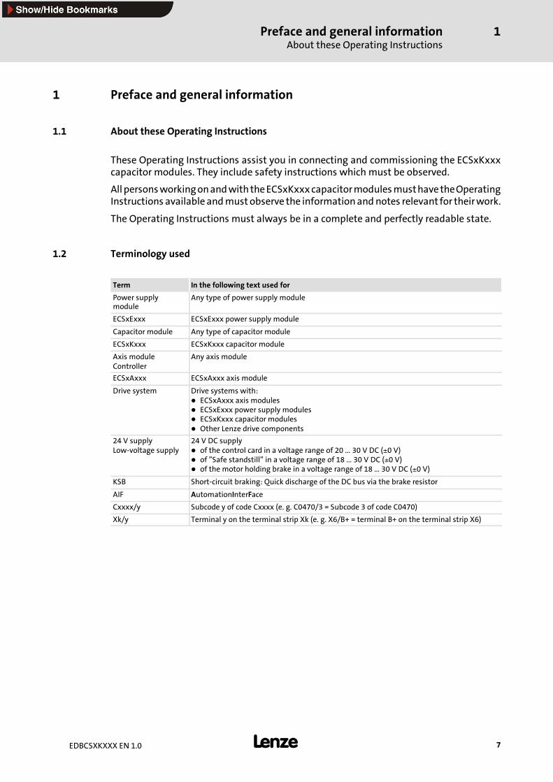
1.2 Terminology used
Term In the following text used for
Power supplymodule
Any type of power supply module
ECSxExxx ECSxExxx power supply module
Capacitor module Any type of capacitor module
ECSxKxxx ECSxKxxx capacitor module
Axis moduleController
Any axis module
ECSxAxxx ECSxAxxx axis module
Drive system Drive systems with:ECSxAxxx axis modulesECSxExxx power supply modulesECSxKxxx capacitor modulesOther Lenze drive components
24 V supplyLow-voltage supply
24 V DC supplyof the control card in a voltage range of 20 ... 30 V DC (±0 V)of ”Safe standstill” in a voltage range of 18 ... 30 V DC (±0 V)of the motor holding brake in a voltage range of 18 ... 30 V DC (±0 V)
KSB Short-circuit braking: Quick discharge of the DC bus via the brake resistor
AIF AutomationInterFace
Cxxxx/y Subcode y of code Cxxxx (e. g. C0470/3 = Subcode 3 of code C0470)
Xk/y Terminal y on the terminal strip Xk (e. g. X6/B+ = terminal B+ on the terminal strip X6)

Preface and general informationLegal regulations
1
8 EDBCSXKXXX EN 1.0
1.3 Legal regulations
Labelling Nameplate CE-identification Manufacturerg
Lenze capacitor modules are clearlydesignated by the date on thenameplate.
Conforms to the EC Low-VoltageDirective
Lenze Drive Systems GmbHPostfach 101352D-31763 Hameln
Application asdirected
ECSxKxxx capacitor modulesmust only be operated under the conditions prescribed in these Instructions.are components– for backing up the DC-bus voltage for the drive system.– for installation into a machine– for assembly with other components to form a machine.are electric units for the installation into control cabinets or similar enclosed operating housing.comply with the requirements of the Low-Voltage Directive.are not machines for the purpose of the Machinery Directive.are not to be used as domestic appliances, but for industrial purposes only.
Drive systems with ECSxKxxx capacitor modulescomply with the EMC Directive ”Electromagnetic compatibility” if they are installed according to the guidelinesof CE-typical drive systems.can be used– for operation on public and non-public mains– in industrial areas.The user is responsible for the compliance of his application with the EC directives.
Any other use shall be deemed inappropriate!
Liability The information, data, and notes in these Instructions met the state of the art at the time of printing. Claimson modifications referring to capacitor modules and components which have already been supplied cannot bederived from the information, illustrations, and descriptions.The specifications, processes, and circuitry described in these Instructions are for guidance only and must beadapted to your own specific application. Lenze does not take responsibility for the suitability of the processand circuit proposals.Lenze does not accept any liability for damage and operating interference caused by:– Disregarding the Operating Instructions– Unauthorised modifications to the capacitor modules– Operating errors– Improper working on and with the capacitor module
Warranty Terms of warranty: See terms of sales and delivery of Lenze Drive Systems GmbH.Warranty claims must be made to Lenze immediately after detecting the deficiency or fault.The warranty is void in all cases where liability claims cannot be made.
Disposal Material recycle disposep
Metal D -
Plastic D -
Assembled PCBs - D

Safety instructionsGeneral safety and application information for Lenze capacitor modules
2
9EDBCSXKXXX EN 1.0
2 Safety instructions
2.1 General safety and application information for Lenze capacitor modules
(according to Low-Voltage Directive 73/23/EWG)
General
During operation, Lenze capacitormodules can include live parts, depending on their typeof protection. Surfaces can be hot.
If the required cover is removed or the modules are used inappropriately or installed oroperated incorrectly, severe damage to persons or material can occur.
For more information please see the documentation.
All operations concerning transport, installation, and commissioning as well asmaintenance must be carried out by qualified, skilled personnel (IEC 364 andCENELEC HD 384 or DIN VDE 0100 and IEC report 664 or DIN VDE 0110 and nationalregulations for the prevention of accidents must be observed).
According to this basic safety information, qualified, skilledpersonnel arepersonswhoarefamiliarwith the assembly, installation, commissioning, andoperationof the product andwho have the qualifications necessary for their occupation.
Application as directed
Capacitor modules are components which are designed for the installation into electricalsystems or machinery. They are not to be used as domestic appliances, but only forindustrial purposes according to EN 61000-3-2. The documentation contains informationabout the compliance with the limit values to EN 61000-3-2.
When installing capacitormodules intomachines, commissioning of the drive controllers(i.e. the starting of operation as directed) is prohibited until it is proven that the machinecorresponds to the regulations of the EC Directive 98/37/EG (Machinery Directive);EN 60204 (VDE 0113) must be observed.
Commissioning (i.e. starting of operation as directed) is only allowed when there iscompliance with the EMC Directive (89/336/EEC).
The capacitor modules meet the requirements of the Low-Voltage Directive 73/23/EWG.The harmonised standards of EN 50178 / DIN VDE 0160 apply to the capacitor modules.
The technical dataand informationontheconnectionconditions canbeobtained fromthenameplate and the documentation. The instructions must be strictly observed.
Warning: The capacitor modules are products with restricted availability according toEN 61800-3. These products can cause interferences in residential premises. If capacitormodules are used in residential premises, corresponding measures are required.
Transport, storage
The notes on transport, storage and appropriate handling must be observed.
Observe the climatic conditions required to EN 50178.

Safety instructionsGeneral safety and application information for Lenze capacitor modules
2
10 EDBCSXKXXX EN 1.0
Installation
The capacitor modulesmust be installed and cooled according to the regulations given inthe corresponding Instructions.
Ensure careful handling andavoidmechanical stress. Donot bendany components anddonot change the insulation distances during transport and handling. Do not touch anyelectronic components and contacts.
Capacitormodules contain electrostatic sensitive deviceswhich can easily be damagedbyinappropriate handling. Do not damage or destroy any electrical components since thismeans hazards for your health!
Electrical connection
Whenworkingon live capacitormodules, the valid national regulations for thepreventionof accidents (e. g. VBG 4) must be observed.
The electrical installation must be carried out in compliance with the correspondingregulations (e. g. cable cross-sections, fusing, PE connection). Additional information canbe obtained from the documentation.
The documentation contains notes for EMC-compliant installation (shielding, earthing,filters and cable routing). These notes must also be observed when using CE-markedcapacitor modules. The manufacturer of the system or machine is responsible for thecompliance with the limit values required by the EMC legislation.
Operation
If necessary, systems including capacitor modules must be equipped with additionalmonitoring and protection devices according to the corresponding safety regulations(e. g. law on technical equipment, regulations for the prevention of accidents). Thecapacitor module can be adapted to your application. Please observe the correspondinginformation given in the documentation.
After the capacitor module has been disconnected from the supply voltage, livecomponentsandpowerconnectionsmustnotbe touched immediatelybecausecapacitorscan be charged. Please observe the corresponding labels on the capacitor module.
All protection covers and doors must be shut during operation.
Note for UL-approved systemwith integrated capacitor modules:
UL warnings are notes which only apply to UL systems. The documentation containsspecial UL-related information.
Maintenance and servicing
The capacitor modules are free of maintenance if the prescribed conditions of operationare observed.
In operating areaswith polluted ambient air, the cooling surfaces of the capacitormodulecan get dirty or the cooling openings can block. Under these conditions a regular cleaningof the cooling surfaces and cooling openings is essential. Do not use sharp or pointedobjects for this purpose!

Safety instructionsGeneral safety and application information for Lenze capacitor modules
2
11EDBCSXKXXX EN 1.0
Disposal
Recycle metals and plastics. Dispose of printed circuit board assemblies according to thestate of the art.
The product-specific safety and application notes in these Instructions must also beobserved!

Safety instructionsResidual hazards
2
12 EDBCSXKXXX EN 1.0
2.2 Residual hazards
Protection of persons
ƒ Before working on the capacitor module, check that no voltage is applied to thepower terminals,
– because the power terminals +UG and -UG at the supply module remain live for atleast 3 minutes after mains switch-off.
– because the power terminals +UG and -UG remain live when the motor is stopped.
ƒ If an error occurs (short circuit to frame or earth fault) a DC residual current mayoccur in the PE conductor. If an earth-leakage circuit breaker (residual currentdevice) is used to protect against direct or indirect contact, only the use of anearth-leakage circuit breaker of type B is permissible on the current supply side. Ifnot, another protective measure is to be used, as for example, separation from theenvironment by double or reinforced insulation or separation from the mains byusing a transformer.
Device protection
ƒ All pluggable connection terminals must only be connected or disconnected whenno voltage is applied.
ƒ The power terminals +UG, -UG and PE are not protected against polarity reversal.
– When wiring, observe the polarity of the power terminals.
ƒ The power may only be converted if the power supply module in the power systemis ready for operation and the charging current limitation is bridged. Otherwise thecharging current limitation can be destroyed.
ƒ If the charging current limitation is active, a cyclic switching of the mains voltage atthe power supply module can overload and destroy the capacitor. Therefore, at leastthree minutes have to pass between two starting operations in case of cyclic mainsswitching over a longer period of time.

Safety instructionsSafety instructions for the installation according to UL or UR
2
13EDBCSXKXXX EN 1.0
2.3 Safety instructions for the installation according to UL or UR
Warnings!General markings:ƒ Use 60/75 °C or 75 °C copper wire only.ƒ Maximum ambient temperature 55 °C, with reduced output current.Terminal tightening torque of lb-in (Nm)ƒ x23– 10.6 ... 13.3 lb-in (1.2 ... 1.5 Nm)
ƒ x26– 4.4 ... 7.1 lb-in (0.5 ... 0.8 Nm)
Wiring diagram AWGƒ x23– AWG 12 ... AWG 8
ƒ x26– AWG 24 ... AWG 12

Safety instructionsDefinition of notes used
2
14 EDBCSXKXXX EN 1.0
2.4 Definition of notes used
The following signal words and symbols are used in this documentation to indicatedangers and important information:
Safety instructions
Structure of safety instructions:
Danger!(characterises the type and severity of danger)Note(describes the danger and gives information about how to prevent dangeroussituations)
Pictograph and signal word Meaning
Danger!
Danger of personal injury through dangerous electricalvoltage.Reference to an imminent danger that may result in death orserious personal injury if the corresponding measures are nottaken.
Danger!Danger of personal injury through a general source of dangerReference to an imminent danger that may result in death orserious personal injury if the corresponding measures are nottaken.
Stop!Danger of property damage.Reference to a possible danger that may result in propertydamage if the corresponding measures are not taken.
Application notes
Pictograph and signal word Meaning
Note! Important note to ensure trouble-free operation
Tip! Useful tip for simple handling
Reference to another documentation
Special safety instructions and application notes for UL and UR
Pictograph and signal word Meaning
Warnings!Safety or application note for the operation of a UL-approveddevice in UL-approved systems.Possibly the drive system is not operated in compliance with ULif the corresponding measures are not taken.
Warnings!Safety or application note for the operation of a UR-approveddevice in UL-approved systems.Possibly the drive system is not operated in compliance with ULif the corresponding measures are not taken.

Technical dataGeneral data/operating conditions
3
15EDBCSXKXXX EN 1.0
3 Technical data
3.1 General data/operating conditions
Standards and operating conditions
Conformity CE Low-Voltage Directive (73/23/EWG)
Approvals UL 508C Power Conversion EquipmentUnderwriter Laboratories (File No. E132659)for USA and Canada
Vibration resistance Accelerational stability up to 0.7 g (Germanischer Lloyd, general conditions)
Climatic conditions Class 3K3 to EN 50178 (without condensation, relative humidity 30 ... 95 %)
Degree of pollution VDE 0110 part 2 pollution degree 2
Packaging (DIN 4180) Delivery packing
Permissible Transport -25 ... +70 °Ctemperature range Storage -25 ... +55 °C
Operation 0 ... +55 °C reduce the rated AC current by 2 %/°C above +40°C
Permissible installation height 0 ... 4000 m amsl reduce rated AC current by 5%/1000 m above 1000 m amsl
Installation Installation into control cabinet
Mounting position Vertically suspended
Free space Above/below ≥ 50 mmp
To the sides Side-by-side mounting without any clearance
General electrical data
EMC Compliance with EN 61800-3
Noise emission Compliance with limit value class A to EN 55011(achieved with application-specific collective filter)
Noise immunity Requirements to EN 61800-3y
Requirements Standard Severity
ESD 1) EN 61000-4-2 3, i. e.8 kV with air discharge6 kV with contact discharge
High frequency in cables EN 61000-4-6 10 V; 0.15 ... 80 MHz
RF interference (enclosure) EN 61000-4-3 3, i. e. 10 V/m;80 ... 1000 MHz
Burst EN 61000-4-4 3/4, i. e. 2 kV/5 kHz
Surge (on mains cable) EN 61000-4-5 3, i. e. 1.2/50 µs1 kV phase-phase2 kV phase PE
Insulation resistance Overvoltage category III to VDE 0110
Discharge current against PE (to EN 50178) > 3.5 mA AC for operation with corresponding controllers
Enclosure IP20 for standard mountingIP20 for mounting in cold-plate techniqueIP20 for mounting in push-through technique; IP54 on the heatsink side
Protective insulation of control circuits Safe disconnection from supply: Double/reinforced insulation to EN 50178;Rated insulation voltage 300 V x √2
1) Noise immunity in the above-mentioned severities must be guaranteed through the control cabinet! The user mustcheck the compliance with the severities!

Technical dataRated data
3
16 EDBCSXKXXX EN 1.0
3.2 Rated data
Rated data Type ECSxK001xxx ECSxK002xxx
Data for operation with upstream supply module on mainsvoltage
Umains [V] 400 480 400 480
DC-bus voltage UDC [V] 0 ... 770
Rated AC current Ir [A] 17,5 35
Rated power PB [kW] 10 20
Rated power with mains choke PBN [kW] 14 28
Capacity C [µF] 705 (±20 %) 1410 (±20 %)
Time constant for charging the capacitors τ [ms] 150
Charging time after mains connection tC_charging [s] 1
Weight ECSEKxxx m [kg] 2.1 3.2g
ECSDKxxx m [kg] 2.1 3.2
ECSCKxxx m [kg] 2.4 3.4
Dimensions ECSEKxxx (W x H x D)[mm]
88.5 x 247 x 176 132 x 247 x 176
ECSDKxxx (W x H x D)[mm]
88.5 x 247 x 176 132 x 247 x 176
ECSCKxxx (W x H x D)[mm]
88.5 x 282 x 123 132 x 282 x 123
Mechanical installationImportant notes
4
17EDBCSXKXXX EN 1.0
4 Mechanical installation
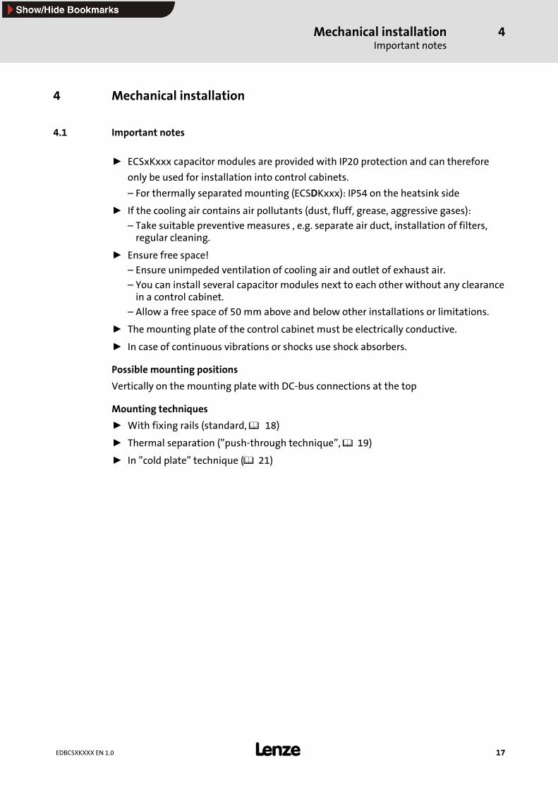
4.1 Important notes
ƒ ECSxKxxx capacitor modules are provided with IP20 protection and can therefore
only be used for installation into control cabinets.
– For thermally separated mounting (ECSDKxxx): IP54 on the heatsink side
ƒ If the cooling air contains air pollutants (dust, fluff, grease, aggressive gases):
– Take suitable preventive measures , e.g. separate air duct, installation of filters,regular cleaning.
ƒ Ensure free space!
– Ensure unimpeded ventilation of cooling air and outlet of exhaust air.
– You can install several capacitor modules next to each other without any clearancein a control cabinet.
– Allow a free space of 50 mm above and below other installations or limitations.
ƒ The mounting plate of the control cabinet must be electrically conductive.
ƒ In case of continuous vibrations or shocks use shock absorbers.
Possible mounting positions
Vertically on the mounting plate with DC-bus connections at the top
Mounting techniques
ƒ With fixing rails (standard, 18)
ƒ Thermal separation (”push-through technique”, 19)
ƒ In ”cold plate” technique ( 21)

Mechanical installationMounting with fixing rails (standard)
4
18 EDBCSXKXXX EN 1.0
4.2 Mounting with fixing rails (standard)
Type ECSEKxxx
For standard mounting into the control cabinet the capacitor module types ECSEKxxxmust be used. The accessories required for mounting are included in the scope of supply.
Dimensions
h he a
g
dbg
a
db
g g
�5
0m
m�
50
mm
ECSXK005
Fig.4-1 Dimensions for standard mounting with fixing rails, ECSEKxxx type
Capacitor modules Dimensions [mm]
Type Size O B D E g h
ECSEK001 1 88.5276 260 176 6.5 10
ECSEK002 2 132276 260 176 6.5
(M6)10
Mounting
For mounting the capacitor module ECSEKxxx proceed as follows:
1. Prepare the fixing holes (see drawing)
2. Take the fixing rails from the accessory kit in the cardboard box.
3. Push the rails into the slots of the heatsink:
– From above: push in the long side.
– From below: push in the short side.
4. Fix the capacitor module onto the mounting plate.

Mechanical installationThermally separated mounting (”push-through technique”)
4
19EDBCSXKXXX EN 1.0
4.3 Thermally separated mounting (”push-through technique”)
Type ECSDKxxx
For thermally separatedmounting the capacitormodules of ECSDKxxx typemust beused.The accessories required for mounting are included in the scope of supply.
ƒ Protection class of the separated cooler: IP54
ƒ When using the push-through technique the pack panel of the control cabinet mustbe a steel plate with a thickness of 3 mm. The plate must be flat or slightly archedinwards (to the capacitor module). This applies to the transverse and lengthwisedirection.
Dimensions
c1 c1
h h
a1 a1
e e1 a
g
gg
db
g
a
db b1
b1
�50
mm
�50
mm Z Z
ECSXK007
Fig.4-2 Dimensions for thermally separated mounting, ECSDKxxx type
Z Mounting cutout (a1 x b1)
Capacitor modules Dimensions [mm]
Type Size O A1 B b1 c1 D E e1 g h
ECSDK001 1 88.5 78.5240 197 75 250 116 58 M5 10 5
ECSDK002 2 132 121.5240 197 75 250 116 58 M5 10.5

Mechanical installationThermally separated mounting (”push-through technique”)
4
20 EDBCSXKXXX EN 1.0
Dimensions of mounting cutout
�6
0m
m�
90
mm
a1 a1
b1
b1
� ��
c1
h
d
c1
g
g
ECSXK063
Fig.4-3 Dimensions of mounting cutout for thermally separated mounting, ECSDKxxx type
Mounting plate Mounting cutout for ECSDK001 Mounting cutout for ECSDK002
Capacitor modules Dimensions [mm]
Type Size A1 b1 c1 D g h
ECSDK001 1 78.5197 75 250 M5 10 5
ECSDK002 2 121.5197 75 250 M5 10.5
Mounting
Stop!When boring through the rear panel of the control cabinet:Seal the fixing screws with a liquid thread seal to ensure the protectionclass IP54 for the separated heatsink.
For mounting the capacitor module ECSDKxxx proceed as follows:
1. Prepare fixing holes for the clips (see drawing).
2. Prepare mounting cutout.
3. Fix the clips.
4. Push the capacitor module into the mounting cutout.
5. Let the capacitor module snap into place at the top and bottom.

Mechanical installationMounting in ”cold plate” technique
4
21EDBCSXKXXX EN 1.0
4.4 Mounting in ”cold plate” technique
Type ECSCKxxx
It is possible to mount the capacitor modules in cold-plate technique, for instance, ontocollective coolers. For thismounting, the capacitormodules type ECSCAxxxmust be used.
Dimensions
c1 c1
a1 a1
e
a
g
gg
b
g
a
d b
�5
0m
m�
50
mm
ECSXK009
Fig.4-4 Dimensions for mounting in ”cold plate” technique, ECSCKxxx type
Capacitor modules Dimensions [mm]
Type Size O A1 B c1 D E g
ECSCK001 1 88.5 60282 50 286 123 M6
ECSCK002 2 132 90282 50 286 123 M6
Stop!Penetration depth of the screws into the cooler: Approx. 15 mm!
Mechanical installationMounting in ”cold plate” technique
4
22 EDBCSXKXXX EN 1.0
Mounting
� � �
ECSXK030
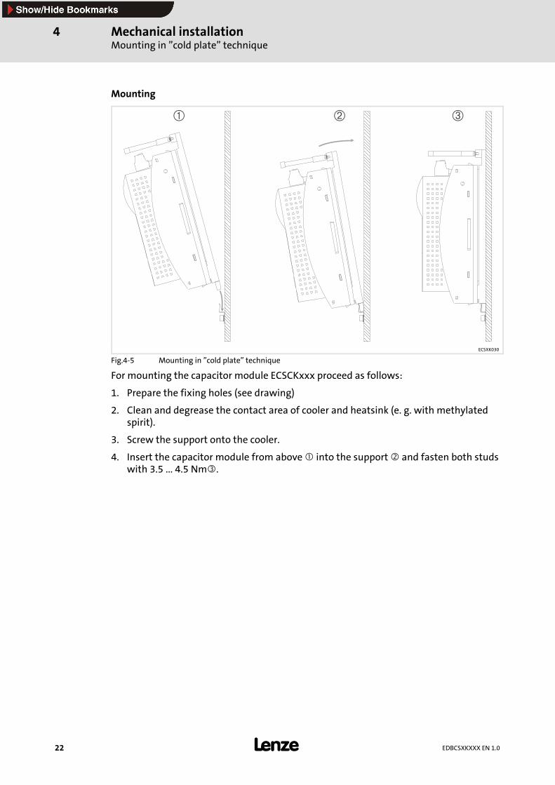
Fig.4-5 Mounting in ”cold plate” technique
For mounting the capacitor module ECSCKxxx proceed as follows:
1. Prepare the fixing holes (see drawing)
2. Clean and degrease the contact area of cooler and heatsink (e. g. with methylatedspirit).
3. Screw the support onto the cooler.
4. Insert the capacitor module from above into the support and fasten both studswith 3.5 ... 4.5 Nm .
Electrical installationImportant notes
Protection of persons
5
23EDBCSXKXXX EN 1.0
5 Electrical installation
5.1 Important notes
Stop!The capacitor module contains electrostatically sensitive components.Prior to assembly and service operations, the personnel must be free ofelectrostatic charge.
5.1.1 Protection of persons
Danger!ƒ Before working on the capacitor module, check that no voltage is applied tothe power terminals,– because the power terminals +UG and -UG remain live for at least threeminutes after mains switch-off.
– because the power terminals +UG and -UG remain live when the motor isstopped.
ƒ If an error occurs (short circuit to frame or earth fault), a DC residual currentmay occur in the PE conductor. If an earth-leakage circuit breaker (residualcurrent device) is used to protect against direct or indirect contact, only theuse of an earth-leakage circuit breaker of type B is permissible on thecurrent supply side. If not, another protective measure is to be used, as forexample, separation from the environment by double or reinforcedinsulation or separation from the mains by using a transformer.
Electrical installationImportant notesDevice protection
5
24 EDBCSXKXXX EN 1.0
5.1.2 Device protection
Stop!ƒ All pluggable connection terminals must only be connected or disconnectedwhen no voltage is applied.
ƒ The power terminals +UG, -UG and PE are not protected against polarityreversal.–When wiring, observe the polarity of the power terminals!
ƒ The power may only be converted if the power supply module in the powersystem is ready for operation and the charging current limitation is bridged.Otherwise the charging current limitation can be destroyed.
ƒ If the charging current limitation is active, a cyclic switching of the mainsvoltage at the power supply module can overload and destroy the capacitor.Therefore, at least three minutes have to pass between two startingoperations in case of cyclic mains switching over a longer period of time!
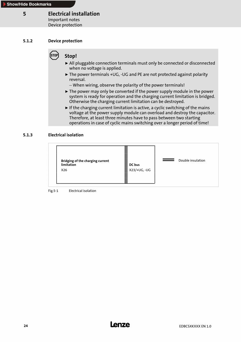
5.1.3 Electrical isolation
Bridging of the charging currentlimitation DC bus
Double insulation
X26 X23/+UG, -UG
Fig.5-1 Electrical isolation
Electrical installationDrive system on the mains
Supply form/electrical supply conditions
5
25EDBCSXKXXX EN 1.0
5.2 Drive system on the mains
These information apply to the drive system, consisting of:
ƒ ECSxExxx power supply module
ƒ ECSxKxxx capacitor module
ƒ ECSxAxxx axis module
ƒ Motor
ƒ Accessories
ƒ Wiring
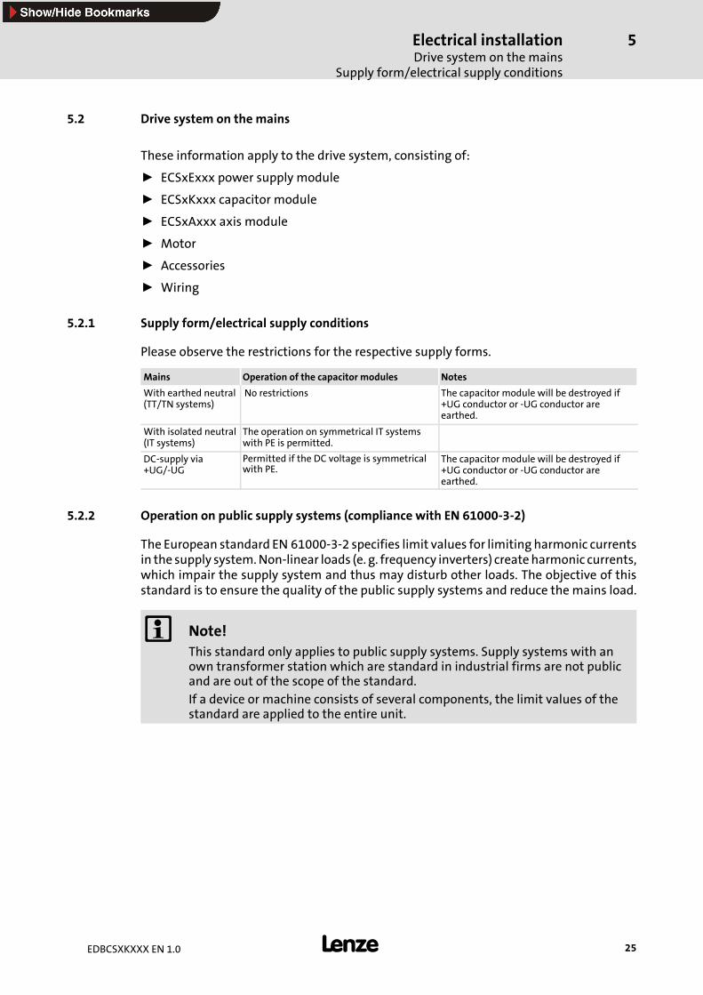
5.2.1 Supply form/electrical supply conditions
Please observe the restrictions for the respective supply forms.
Mains Operation of the capacitor modules Notes
With earthed neutral(TT/TN systems)
No restrictions The capacitor module will be destroyed if+UG conductor or -UG conductor areearthed.
With isolated neutral(IT systems)
The operation on symmetrical IT systemswith PE is permitted.
DC-supply via+UG/-UG
Permitted if the DC voltage is symmetricalwith PE.
The capacitor module will be destroyed if+UG conductor or -UG conductor areearthed.
5.2.2 Operation on public supply systems (compliance with EN 61000-3-2)
The European standard EN 61000-3-2 specifies limit values for limiting harmonic currentsin the supply system.Non-linear loads (e. g. frequency inverters) createharmonic currents,which impair the supply system and thus may disturb other loads. The objective of thisstandard is to ensure the quality of the public supply systems and reduce the mains load.
Note!This standard only applies to public supply systems. Supply systems with anown transformer station which are standard in industrial firms are not publicand are out of the scope of the standard.If a device or machine consists of several components, the limit values of thestandard are applied to the entire unit.

Electrical installationInstallation of a DC-typical drive system
5
26 EDBCSXKXXX EN 1.0
5.3 Installation of a DC-typical drive system
General notes
ƒ The electromagnetic compatibility of a machine depends on the type of installationand care taken.Especially consider the following:
– Structure
– Filtering
– Shielding
– Earthing
ƒ For diverging installations, the conformity to the CE EMC Directive requires a checkof the machine or system regarding the EMC limit values. This is valid, for instance,when:
– Using unshielded cables
– Using collective suppression filters in place of the assigned RFI filters
– Operating without RFI filters
ƒ The compliance of the machine application with the EMC Directive is in theresponsibility of the user.
– If you observe the following measures, you can assume that the machine willoperate without any EMC problems caused by the drive system and thatcompliance with the EMC Directive and the EMC law is achieved.
– If devices which do not comply with the CE requirement concerning noiseimmunity EN 61000-6-2 are operated close to the axis modules, these devices maybe disturbed electromagnetically by the axis modules.
Structure
ƒ Install the capacitor module between the power supply module and the axismodule(s)..
– For cable lengths > 5 mwe recommend to install the capacitor module as close aspossible to the axis module with the highest power.
ƒ Connect power supply modules, capacitor modules, axis modules, RFI filters, andmains choke to the earthed mounting plate with a large surface:
– Mounting plates with conductive surfaces (zinc-coated or stainless steel) allowpermanent contact.
– Painted plates are not suitable for the installation in accordance with the EMC.
ƒ If you use several mounting plates:
– Connect the mounting plates electrically with a large surface (e.g. with copperbands).
ƒ Ensure the separation of motor cable and signal or mains cable.
ƒ Do not use the same terminal strip for mains input and motor output.
ƒ Lay the cables as close as possible to the reference potential. Freely suspendedcables act like aerials.

Electrical installationInstallation of a DC-typical drive system
5
27EDBCSXKXXX EN 1.0
Filtering
ƒ Use RFI filters and mains chokes which are assigned to the power supply modules:
– RFI filters reduce impermissible high-frequency interferences to a permissiblevalue.
– Mains chokes reduce low-frequency interferences which depend on the motorcable and its length.
Shielding
ƒ Connect the motor cable shield to the axis module
– with the EMC accessories ECSZS000X0B.
– to the mounting plate below the axis module with a large surface.
– Recommendation: For the shield connection, use earthing clamps on bare metalmounting surfaces.
ƒ If contactors, motor-protecting switches or terminals are located in the motor cable:
– Connect the shields of the connected cables to the mounting plate, too, with asurface as large as possible.
ƒ Connect the shield in the motor terminal box or on the motor housing to PE:
– Metal glands at the motor terminal box ensure a connection of the shield and themotor housing.
ƒ Shield the control cables:
– Connect both shields of the digital control cables.
– Connect one shields of the analog control cables.
– Always connect the shields to the shield connection at the controller over theshortest possible distance.
ƒ Using the axis modules in residential areas:
– Additionally dampen the shield in order to limit the interfering radiation: ≥ 10 dB .This can be realised by using standard, closed, metallic, and earthed controlcabinets or boxes.
Earthing
ƒ Earth all metallically conductive components (power supply module, capacitormodule, axis module, RFI filter, motor filter, mains choke) using suitable cablesconnected to a central point (PE bar).
ƒ Maintain the minimum cross-sections prescribed in the safety regulations:
– For the EMC, not the cable cross-section is important, but the surface and thecontact with a cross-section as large as possible, i.e. large surface.
Electrical installationPower connectionsTerminal assignment of the power connections
5
28 EDBCSXKXXX EN 1.0
5.4 Power connections
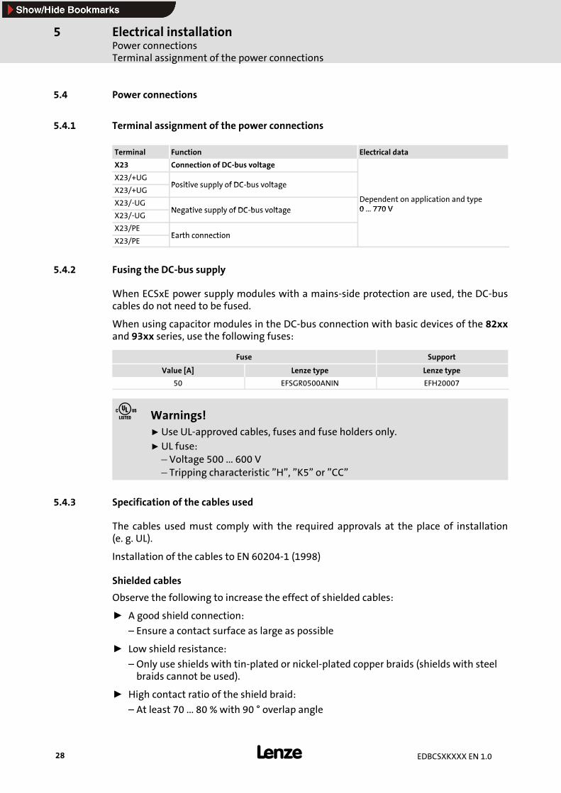
5.4.1 Terminal assignment of the power connections
Terminal Function Electrical data
X23 Connection of DC-bus voltage
X23/+UGPositive supply of DC bus voltage
X23/+UGPositive supply of DC-bus voltage
D d t li ti d tX23/-UGNegative supply of DC bus voltage
Dependent on application and type0 770 V
X23/-UGNegative supply of DC-bus voltage 0 ... 770 V
X23/PEEarth connection
X23/PEEarth connection
5.4.2 Fusing the DC-bus supply
When ECSxE power supply modules with a mains-side protection are used, the DC-buscables do not need to be fused.
When using capacitor modules in the DC-bus connection with basic devices of the 82xxand 93xx series, use the following fuses:
Fuse Support
Value [A] Lenze type Lenze type
50 EFSGR0500ANIN EFH20007
Warnings!ƒ Use UL-approved cables, fuses and fuse holders only.ƒ UL fuse:– Voltage 500 ... 600 V– Tripping characteristic ”H”, ”K5” or ”CC”
5.4.3 Specification of the cables used
The cables used must comply with the required approvals at the place of installation(e. g. UL).
Installation of the cables to EN 60204-1 (1998)
Shielded cables
Observe the following to increase the effect of shielded cables:
ƒ A good shield connection:
– Ensure a contact surface as large as possible
ƒ Low shield resistance:
– Only use shields with tin-plated or nickel-plated copper braids (shields with steelbraids cannot be used).
ƒ High contact ratio of the shield braid:
– At least 70 ... 80 % with 90 ° overlap angle
Electrical installationPower connections
Specification of the cables used
5
29EDBCSXKXXX EN 1.0
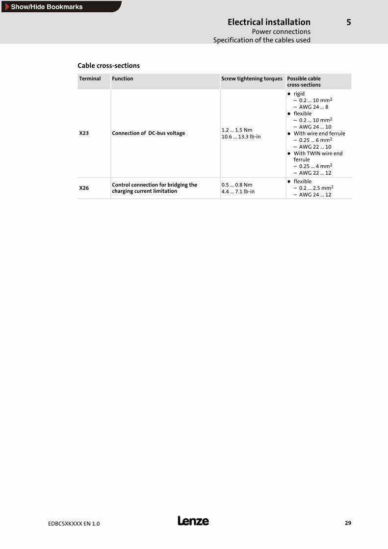
Cable cross-sections
Terminal Function Screw tightening torques Possible cablecross-sections
X23 Connection of DC-bus voltage 1.2 ... 1.5 Nm10.6 ... 13.3 lb-in
rigid– 0.2 ... 10 mm2
– AWG 24 ... 8flexible– 0.2 ... 10 mm2
– AWG 24 ... 10With wire end ferrule– 0.25 ... 6 mm2
– AWG 22 ... 10With TWIN wire endferrule– 0.25 ... 4 mm2
– AWG 22 ... 12
X26 Control connection for bridging thecharging current limitation
0.5 ... 0.8 Nm4.4 ... 7.1 lb-in
flexible– 0.2 ... 2.5 mm2
– AWG 24 ... 12

Electrical installationControl connection
5
30 EDBCSXKXXX EN 1.0
5.5 Control connection
Terminal Function Electrical data
X26 Connection for bridging the charging currentlimitation
21.8 ... 30 V DC,max. 1.5 A
The polarity does not influence the function of the charging current limitation.

Electrical installationWiring
Operation with ECSxE power supply module
5
31EDBCSXKXXX EN 1.0
5.6 Wiring
5.6.1 Operation with ECSxE power supply module
Install the capacitor module ECSxKxxx between the power supply module and the axismodule(s).
If the total cable length in the DC-bus connection is longer than 5 m, install the capacitormodule as close as possible to the axis module with the highest power.
Stop!ƒ Permanently bridge the charging current limitation (X26) of the capacitormodule (X26 = HIGH).
ƒ Only release the controller (X6/SI1 = HIGH) if the power supply moduleECSxE displays ”Ready for operation” (X6/DO1 = HIGH).
L3
N
PE
L1
L2
F1...F3
Z1
F4
K1
ECSxKxxx
K1
K1
L1 L2 L3
ECSxExxx
PE
X21
+UG +UG +UG+UG +UG-UG -UG -UG-UG -UGPE PE PEPE PE
X22 X23
Off
On
+UGBR1
X26
BR0
PES
PES
U V W
ECSxAxxx
X23
PE
X24
B1 B2
X25 X7
M3~
PE
PES
PES
R�
*1
2
6
. . .
T1
T2
X6
DI1
DI2
DO
1
D2
4
+2
4V
GN
D
GND
24 V DC
+
-
Ctrl. enable
K1
ECSXX004
Fig.5-2 Wiring of the capacitor module ECSxK with power supply module ECSxE
HF shield termination by large-surface PE connection
Twisted cables
* 1 System cable - feedback
Ctrl.enable Terminal X6/SI1 of the connected axis modules (controller enable)

Electrical installationWiringOperation with ECSxE power supply module
5
32 EDBCSXKXXX EN 1.0
t [s]
HIGH (1)
LOW (0)
ECSxA: X6/SI1 (CINH)
ECSxE: X6/DO1
t [s]
100 %
0 %
t [s]
HIGH (1)
LOW (0)
ECSxK: X26 (24 V DC)
ECSxE: X6/DI1
ECSxE: X6/DI2
t [s]
HIGH (1)
LOW (0)
K1
UZK
ECSXK010
Fig.5-3 Level/time diagrams for operation with ECSxE power supply module
Electrical installationWiring
Operation with another supplier
5
33EDBCSXKXXX EN 1.0
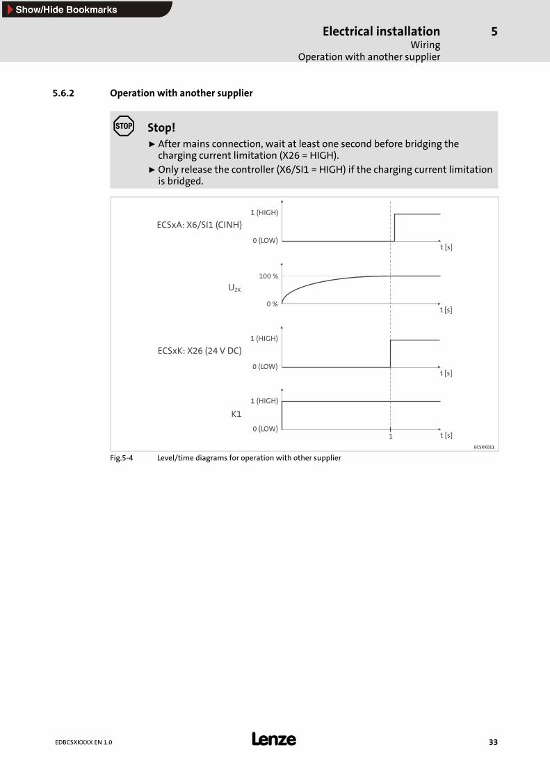
5.6.2 Operation with another supplier
Stop!ƒ After mains connection, wait at least one second before bridging thecharging current limitation (X26 = HIGH).
ƒ Only release the controller (X6/SI1 = HIGH) if the charging current limitationis bridged.
t [s]
1 (HIGH)
0 (LOW)
ECSxA: X6/SI1 (CINH)
t [s]
100 %
0 %
t [s]
1 (HIGH)
0 (LOW)
ECSxK: X26 (24 V DC)
t [s]
1 (HIGH)
0 (LOW)
K1
UZK
1
ECSXK011
Fig.5-4 Level/time diagrams for operation with other supplier

Commissioning6
34 EDBCSXKXXX EN 1.0
6 Commissioning
Before you start
Prior to initial switch-on of the drive system, check the wiring of the capacitor module forcompleteness, short-circuit, and earth fault:
ƒ Power connection (X23):
– Polarity of the DC-bus voltage supply via terminals +UG and -UG
ƒ Control connection (X26):
– Wiring adjusted to the signal assignment of the control terminals.
Further information on commissioning the drive system can be obtained fromthe documentations for the power supply module and axis module.
AppendixOverview of accessories
7
35EDBCSXKXXX EN 1.0
7 Appendix
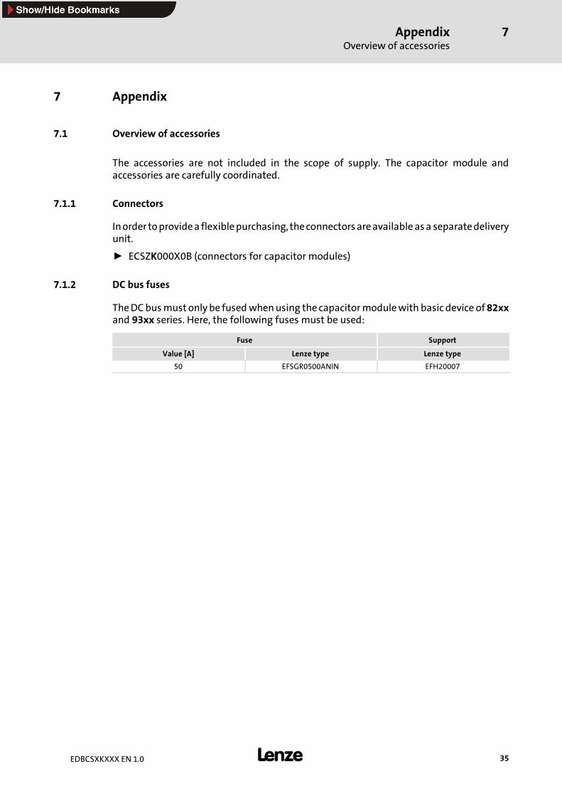
7.1 Overview of accessories
The accessories are not included in the scope of supply. The capacitor module andaccessories are carefully coordinated.
7.1.1 Connectors
Inorder toprovidea flexiblepurchasing, theconnectorsareavailable asa separatedeliveryunit.
ƒ ECSZK000X0B (connectors for capacitor modules)
7.1.2 DC bus fuses
TheDCbusmust only be fusedwhenusing the capacitormodulewith basic device of82xxand 93xx series. Here, the following fuses must be used:
Fuse Support
Value [A] Lenze type Lenze type
50 EFSGR0500ANIN EFH20007

AppendixIndex
7
36 EDBCSXKXXX EN 1.0
7.2 Index
AAccessories, 35
- connectors, 35
- DC bus fuses, 35
Appendix, 35
Application as directed, 8
Approvals, 15
BBridging of charging current limitation, connection, 30
CCable cross-sections, 29
Capacitor module, 7
- application as directed, 8
- labelling, 8
- type ECSCKxxx, mounting in ”cold plate” technique, 21
- type ECSDKxxx, thermally separated mounting, 19
- type ECSEKxxx, mounting with fixing rails, 18
Capacitor module, connection, 31
Capacity, 16
CE-typical drive system, 26
- earthing, 27
- filtering, 27
- installation, 26
- shielding, 27
- structure, 26
Charging current limitation, bridging, connection, 30
Charging time, capacitors, 16
Climatic conditions, 15
Commissioning, 34
Conformity, 15
Connection - bridging of charging current limitation, 30
Connection of DC bus voltage, 28
Connection, capacitor module, 31
Connectors, 35
Control connection (X26), terminal assignment, 30
Controller, 7
DDC bus fuses, 28
DC bus supply, fusing, 28
DC bus voltage, 16
DC bus voltage, connection, 28
DC-bus fuses, 35
Definition of notes used, 14
Definitions, 7
Degree of pollution, 15
Device protection, 12
Dimensions, 16
Discharge current against PE, 15
Disposal, 8 , 11
Drive system, 7
Drive system on the mains, 25
- operation on public supply systems, EN 61000-3-2, 25
- supply forms / electrical supply conditions, 25
EEarthing, EMC, 27
Electrical data, general, 15
Electrical installation, 23
- control connection (X26), terminal assignment, 30
- drive system on the mains, 25operation on public supply systems, 25supply forms / electrical supply conditions, 25
- important notes, 23electrical isolation, 24protection of persons, 23
- installation of a CE-typical drive system, 26earthing, 27filtering, 27shielding, 27structure, 26
- power connectionsconnection of capacitor module, 31DC bus supply, fusing, 28specification of cables used, 28
- power connections (X23), terminal assignment, 28
Electrical isolation, 24
Electromagnetic compatibility, 15
EMC, 15
- earthing, 27
- filtering, 27
- shielding, 27
EN 61000-3-2, operation on public supply systems, 25
Enclosure, 15
FFiltering, EMC, 27

AppendixIndex
7
37EDBCSXKXXX EN 1.0
Free space, 15
Fuses, 28 , 35
GGeneral electrical data, 15
IInstallation, 15
Installation height, 15
Installation of a CE-typical drive system, 26
- earthing, 27
- filtering, 27
- shielding, 27
- structure, 26
Installation, electrical, 23
- control connection (X26), terminal assignment, 30
- drive system on the mains, 25operation on public supply systems, 25supply forms / electrical supply conditions, 25
- important notes, 23electrical isolation, 24protection of persons, 23
- installation of a CE-typical drive system, 26earthing, 27filtering, 27shielding, 27structure, 26
- power connection, connection of capacitor module, 31
- power connectionsDC bus supply, fusing, 28specification of cables used, 28
- power connections (X23), terminal assignment, 28
Installation, mechanical, 17
- important notes, 17
- mounting in ”cold plate” technique, type ECSCKxxx, 21
- mounting with fixing rails, type ECSEKxxx, 18
- thermally separated mounting, type ECSDKxxx, 19
Insulation resistance, 15
LLabelling, capacitor module, 8
Legal regulations, 8
Liability, 8
Low-voltage supply, 7
MManufacturer, 8
Mechanical installation, 17
- important notes, 17
- mounting in ”cold plate” technique, type ECSCKxxx, 21
- mounting with fixing rails, type ECSEKxxx, 18
- thermally separated mounting, type ECSDKxxx, 19
Mounting in ”cold plate” technique, type ECSCKxxx, 21
Mounting position, 15
Mounting with fixing rails, type ECSEKxxx, 18
NNoise emission, 15
Noise immunity, 15
Notes, definition, 14
OOperating conditions, 15
Operation on public supply systems, EN 61000-3-2, 25
PPackaging, 15
Power, 16
Power connection, connection of capacitor module, 31
Power connections, 28
- DC bus supply, fusing, 28
- specification of cables used, 28cable cross-sections, 29shielded cables, 28
Power connections (X23), terminal assignment, 28
Power reduction, 15
Power supply module, 7
Protection of persons, 12
RRated current, 16
Rated data, 16
Rated power, 16
Residual hazards, 12

AppendixIndex
7
38 EDBCSXKXXX EN 1.0
SSafety instructions, 9
- definition, 14
- design, 14
- device protection, 12
- general, for Lenze capacitor modules, 9
- protection of persons, 12
Shielded cables, 28
Shielding, EMC, 27
Specification of cables used, 28
- cable cross-sections, 29
- shielded cables, 28
Standards, 15
Supply forms / electrical supply conditions, 25
TTechnical data, 15- general electrical data, 15- operating conditions, 15- rated data, 16- standards, 15
Temperature range, 15
Terminal assignment- control connection (X26), 30- power connections (X23), 28
Thermally separated mounting, type ECSDKxxx, 19
VVibration resistance, 15
WWarranty, 8
Weight, 16
Wiring, 31

Appendix 7
39EDBCSXKXXX EN 1.0
Lenze Drive Systems GmbHHans-Lenze-Straße 131855 AerzenGermany
EDBCSXKXXX 1.0 09/2004 TD14 2004
+49 (0) 51 54 82-0Service 00 80 00 24 4 68 77 (24 h helpline)Service +49 (0) 51 54 82-1112
E-Mail [email protected] www.Lenze.com
10 9 8 7 6 5 4 3 2 1