-PEEKIT- MAGAZINE Ce fichier vous est offert par Peek It ...

Tech Hour
Tenue au feu des composites
Etude des comportements thermique et mécanique de composites aéronautiques soumis au feu
27/02/2018

ORGANISATEURS TECH HOUR TENUE AU FEU DES COMPOSITES
TENUE AU FEU DES COMPOSITES
œ
FORMAT ET DÉROULÉ
•••
•
•
•••
•
Étude des comportements thermique et mécanique de composites aéronautiques soumis
au feu
B. VIEILLE1, A. COPPALLE2, Y. CARPIER1, E. SCHUHLER2, F. BARBE1
1 Groupe de Physique des Matériaux, UMR 6634 CNRS2 CORIA, UMR 6614 CNRS
Université et INSA Rouen, avenue de l’Université, 76801 St Etienne du Rouvray, France
[email protected]@coria.fr
Tech’Hour NAE, 27 février 2018
Introduction ConclusionsFire exposure Mechanical behaviorGeneralities Numerical simulation
1
2
IntroductionIntroduction ConclusionsFire exposure Mechanical behaviorGeneralities Numerical simulation
Competition fuels innovation: what materials for tomorrow’s aircrafts?
Introduction
3
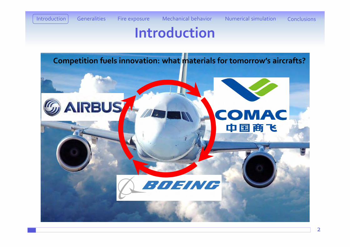
A few examples of TP-based composites parts in aeronautics
What about high-temperatureapplications ?
[Maruszczak, 2007]
Introduction ConclusionsFire exposure Mechanical behaviorGeneralities Numerical simulation
IntroductionIntroduction ConclusionsFire exposure Mechanical behaviorGeneralities Numerical simulation
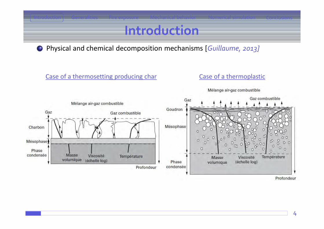
Physical and chemical decomposition mechanisms [Guillaume, 2013]
4
Case of a thermosetting producing char Case of a thermoplastic
IntroductionIntroduction ConclusionsFire exposure Mechanical behaviorGeneralities Numerical simulation
Fire
Crack
Pore
Fibre Fibre + matrixDelamination
Pyrolysis front
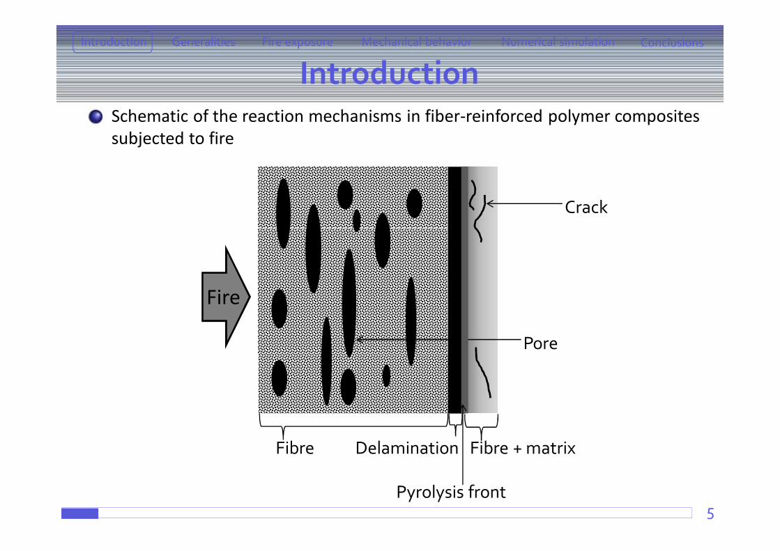
Schematic of the reaction mechanisms in fiber-reinforced polymer composites subjected to fire
5
6
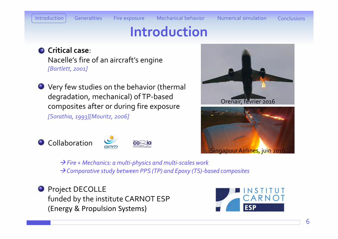
Critical case: Nacelle’s fire of an aircraft’s engine[Bartlett, 2001]
Very few studies on the behavior (thermal degradation, mechanical) of TP-basedcomposites after or during fire exposure[Sorathia, 1993][Mouritz, 2006]
Collaboration
Fire + Mechanics: a multi-physics and multi-scales workComparative study between PPS (TP) and Epoxy (TS)-based composites
Project DECOLLEfunded by the institute CARNOT ESP (Energy & Propulsion Systems)
IntroductionIntroduction ConclusionsFire exposure Mechanical behaviorGeneralities Numerical simulation
Singapour Airlines, juin 2016
Orenair, février 2016
7
IntroductionIntroduction ConclusionsFire exposure Mechanical behaviorGeneralities Numerical simulation
Composite materials behaviour under fire conditions + mech. loading
GPM (Groupe de Physique des Matériaux)TP-based composite laminates for high-temperature applications
Fatigue, impact, damage tolerance, fire behavior PhD of Yann Carpier
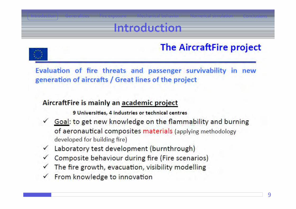
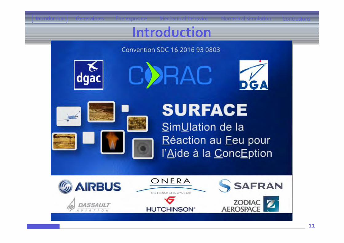
CORIA (COmplexe de Recherche Interprofessionnel en Aérothermochimie)European Project AircraftFire (http://www.aircraftfire.eu)Projet Surface, collaboration with Airbus
Interaction fire/composite structures PhD of Eliot Schuhler
Question:What about the interaction heat / fire / physical-chemical-mechanicalbehavior ?
8
Introduction ConclusionsFire exposure Mechanical behaviorGeneralities Numerical simulation
Introduction
9
Introduction ConclusionsFire exposure Mechanical behaviorGeneralities Numerical simulation
Introduction
10
Introduction ConclusionsFire exposure Mechanical behaviorGeneralities Numerical simulation
Introduction
11
Introduction ConclusionsFire exposure Mechanical behaviorGeneralities Numerical simulation
Introduction
Presentation outlineGeneralities Aeronautics context What materials ? Experimental procedure
Fire exposure Cone calorimeter
ATG + Lamp furnacePropane-flame burner
Mechanical behavior under fire exposurePost-fire testingCombined testing
Numerical simulationCorrelation between temperature distribution and matrix thermal degradation
Conclusions and perspectives12
Introduction ConclusionsFire exposure Mechanical behaviorGeneralities Numerical simulation
Generalities Aeronautics context What materials ? Experimental procedure
Fire exposure Cone calorimeter
ATG + Lamp furnacePropane-flame burner
Mechanical behavior under fire exposurePost-fire testingCombined testing
Numerical simulationCorrelation between temperature distribution and matrix thermal degradation
Conclusions and perspectives13
Introduction ConclusionsFire exposure Mechanical behaviorGeneralities Numerical simulation
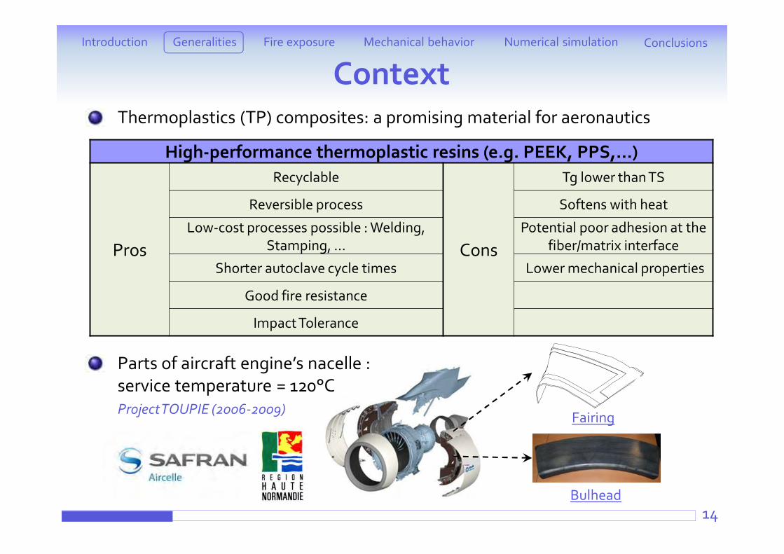
ContextThermoplastics (TP) composites: a promising material for aeronautics
Parts of aircraft engine’s nacelle : service temperature = 120°CProject TOUPIE (2006-2009)
Bulhead14
High-performance thermoplastic resins (e.g. PEEK, PPS,…)
Pros
Recyclable
Cons
Tg lower than TS
Reversible process Softens with heat
Low-cost processes possible : Welding, Stamping, …
Potential poor adhesion at the fiber/matrix interface
Shorter autoclave cycle times Lower mechanical properties
Good fire resistance
Impact Tolerance
Fairing
Introduction ConclusionsFire exposure Mechanical behaviorGeneralities Numerical simulation
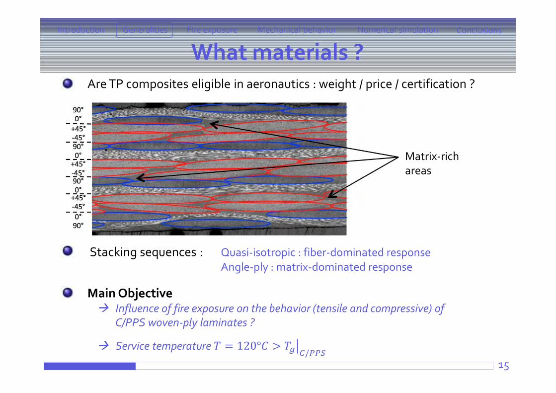
What materials ?
15
Are TP composites eligible in aeronautics : weight / price / certification ?
Materials 7 plies pre-preg laminates Matrix :
PolyPhenylene Sulfide PPS (Ticona) 5 HS carbon fibers satin weave
(Toray T300 3K 5HS) Fibers volume fraction 50%
Stacking sequences : Quasi-isotropic : fiber-dominated responseAngle-ply : matrix-dominated response
Main Objective Influence of fire exposure on the behavior (tensile and compressive) of
C/PPS woven-ply laminates ?
Service temperature = 120° >/
Warp Weft
Tg (°C) Crystallinity (%)
C/PPS 107,07 ± 0,82 26,7 ± 1,76
[Blond, 2011]Matrix-richareas
Introduction ConclusionsFire exposure Mechanical behaviorGeneralities Numerical simulation
Experimental procedure
16
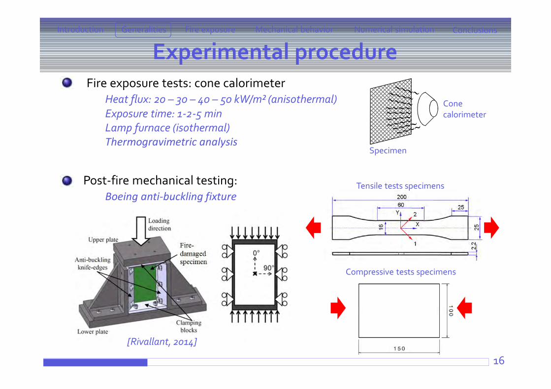
Fire exposure tests: cone calorimeterHeat flux: 20 – 30 – 40 – 50 kW/m² (anisothermal)Exposure time: 1-2-5 minLamp furnace (isothermal)Thermogravimetric analysis
Post-fire mechanical testing:Boeing anti-buckling fixture
Introduction ConclusionsFire exposure Mechanical behaviorGeneralities Numerical simulation
Conecalorimeter
Specimen
[Rivallant, 2014]
Tensile tests specimens
Compressive tests specimens
17
Introduction ConclusionsFire exposure Mechanical behaviorGeneralities Numerical simulation
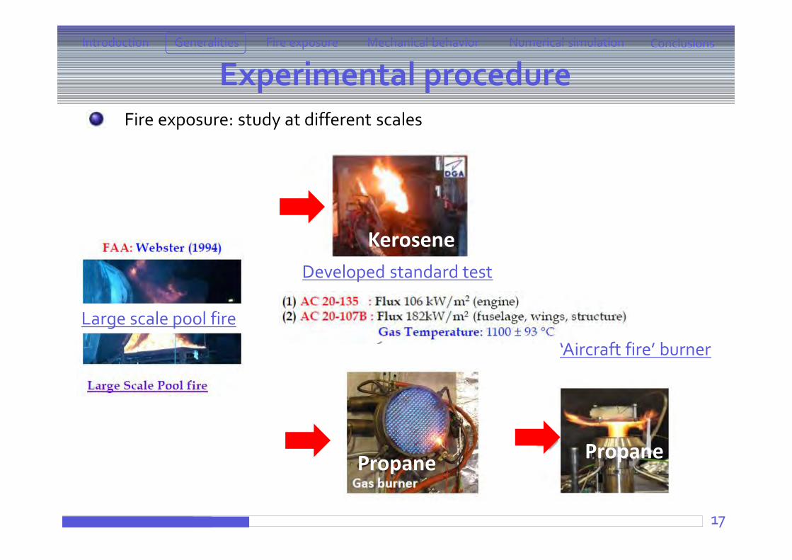
Experimental procedureFire exposure: study at different scales
Large scale pool fire
‘Aircraft fire’ burner
Propane
Developed standard test
Kerosene
Propane
18
Introduction ConclusionsFire exposure Mechanical behaviorGeneralities Numerical simulation
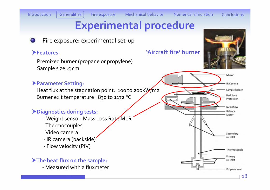
Experimental procedureFire exposure: experimental set-up
Premixed burner (propane or propylene)Sample size :5 cm
Features:
Parameter Setting:Heat flux at the stagnation point: 100 to 200kW/m2Burner exit temperature : 830 to 1172 °C
Diagnostics during tests:- Weight sensor: Mass Loss Rate MLRThermocouplesVideo camera
- IR camera (backside)- Flow velocity (PIV)
‘Aircraft fire’ burner
The heat flux on the sample:- Measured with a fluxmeter
19
Introduction ConclusionsFire exposure Mechanical behaviorGeneralities Numerical simulation
Experimental procedureFire exposure: Propane (Aircraft Fire) burner
Same heat fluxes and temperature at the material surface Reduced cost (sample 4x4 cm2) More information: not only pass/fail test Burning rate (HRR) proportional to MLR Pyrolysis time, Peak of MLR, Burning time, mean burning time, etc… Larger number of tests More working parameters (Heat fluxes, Pressure, Load, thickness…
Generalities Aeronautics context What materials ? Experimental procedure
Fire exposure Cone calorimeter
ATG + Lamp furnacePropane-flame burner
Mechanical behavior under fire exposurePost-fire testingCombined testing
Numerical simulationCorrelation between temperature distribution and matrix thermal degradation
Conclusions and perspectives20
Introduction ConclusionsFire exposure Mechanical behaviorGeneralities Numerical simulation
GPM Eircap
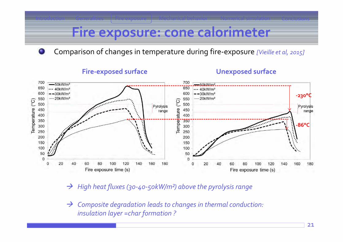
Fire exposure: cone calorimeter
21
Comparison of changes in temperature during fire-exposure [Vieille et al, 2015]
High heat fluxes (30-40-50kW/m²) above the pyrolysis range
Composite degradation leads to changes in thermal conduction: insulation layer =char formation ?
Introduction ConclusionsFire exposure Mechanical behaviorGeneralities Numerical simulation
Fire-exposed surface Unexposed surface
-230°C
-86°C
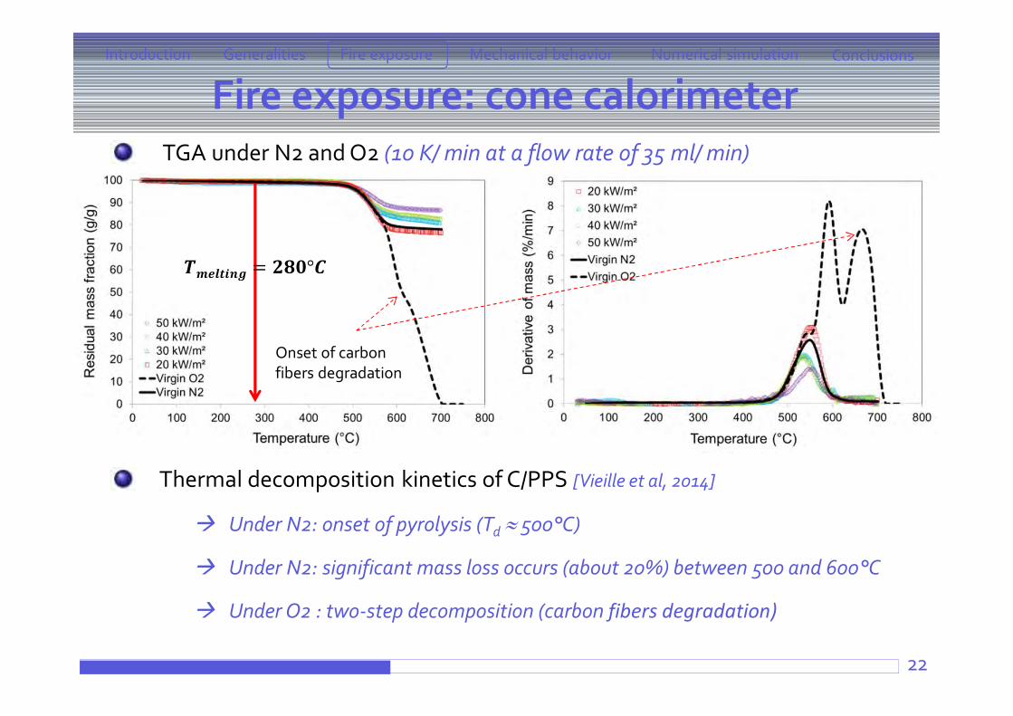
Fire exposure: cone calorimeter
22
TGA under N2 and O2 (10 K/ min at a flow rate of 35 ml/ min)
Thermal decomposition kinetics of C/PPS [Vieille et al, 2014]
Under N2: onset of pyrolysis (Td 500°C)
Under N2: significant mass loss occurs (about 20%) between 500 and 600°C
Under O2 : two-step decomposition (carbon fibers degradation)
Introduction ConclusionsFire exposure Mechanical behaviorGeneralities Numerical simulation
Onset of carbonfibers degradation
= °
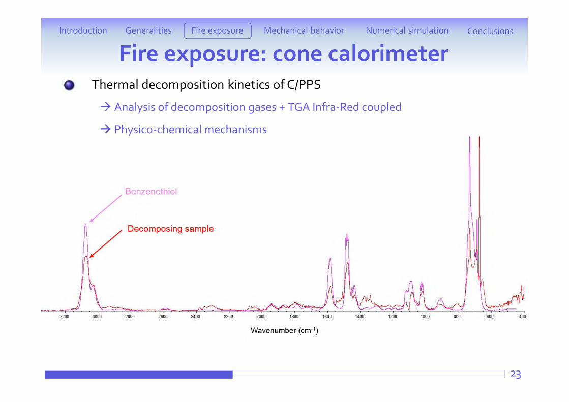
Thermal decomposition kinetics of C/PPS
Analysis of decomposition gases + TGA Infra-Red coupled
Physico-chemical mechanisms
Fire exposure: cone calorimeterIntroduction ConclusionsFire exposure Mechanical behaviorGeneralities Numerical simulation
23
24
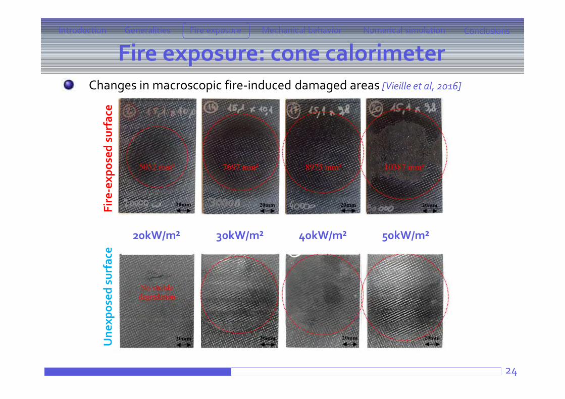
Changes in macroscopic fire-induced damaged areas [Vieille et al, 2016]
Introduction ConclusionsFire exposure Mechanical behaviorGeneralities Numerical simulation
Fire exposure: cone calorimeter
20kW/m² 30kW/m² 40kW/m² 50kW/m²
Fire
-exp
osed
sur
face
Une
xpos
ed s
urfa
ce
Fire exposure: cone calorimeter
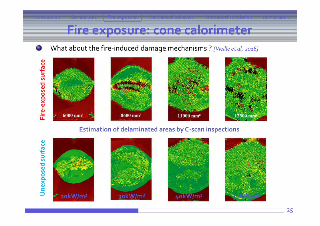
25
What about the fire-induced damage mechanisms ? [Vieille et al, 2016] Fi
re-e
xpos
ed s
urfa
ceU
nexp
osed
sur
face
Estimation of delaminated areas by C-scan inspections
Introduction ConclusionsFire exposure Mechanical behaviorGeneralities Numerical simulation
20kW/m² 30kW/m² 40kW/m² 50kW/m²
Fire exposure: cone calorimeter
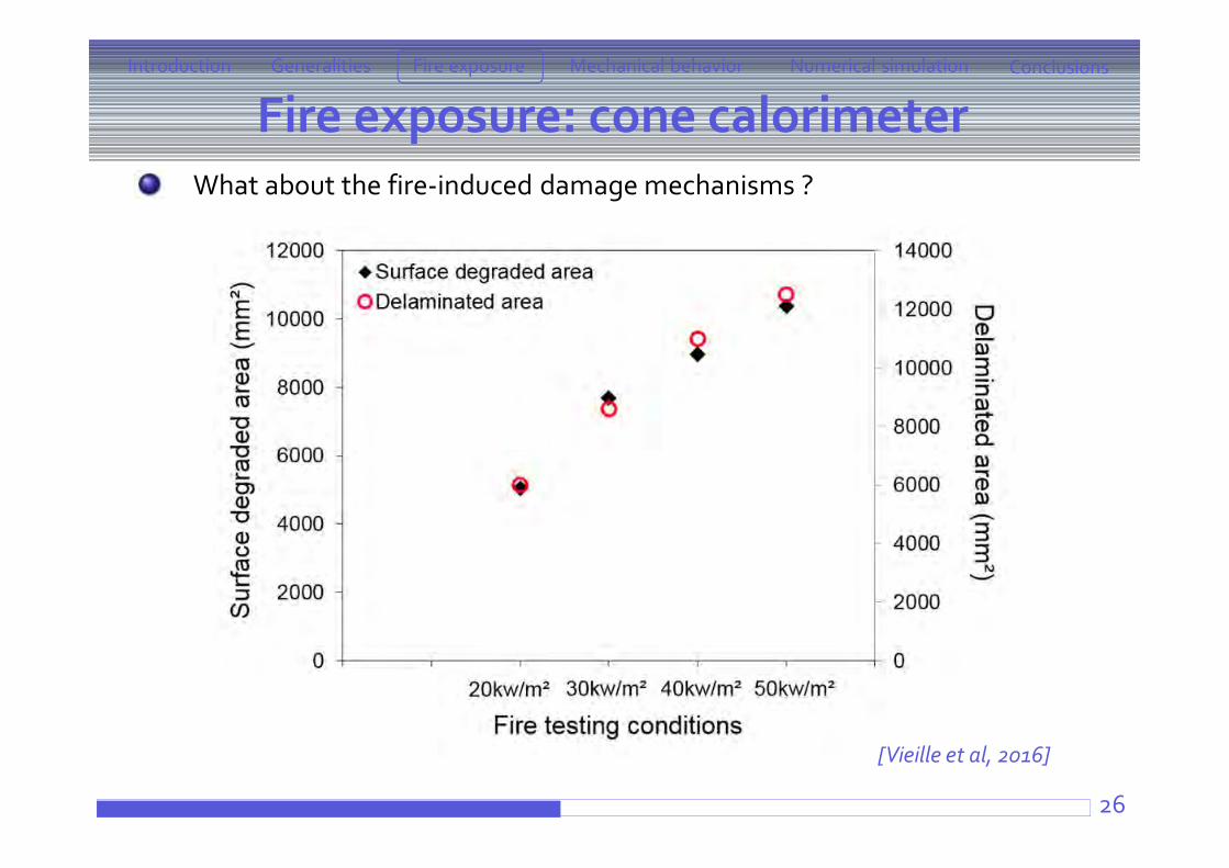
26
What about the fire-induced damage mechanisms ?
[Vieille et al, 2016]
Introduction ConclusionsFire exposure Mechanical behaviorGeneralities Numerical simulation
27
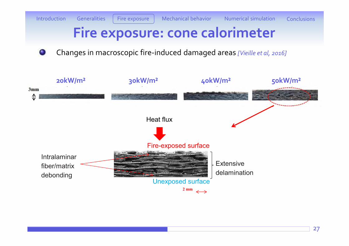
Changes in macroscopic fire-induced damaged areas [Vieille et al, 2016]
Introduction ConclusionsFire exposure Mechanical behaviorGeneralities Numerical simulation
Fire exposure: cone calorimeter
20kW/m² 30kW/m² 40kW/m² 50kW/m²
Extensive delamination
Heat flux
Fire-exposed surface
Unexposed surface2 mm
Intralaminarfiber/matrix debonding
Fire exposure: cone calorimeter
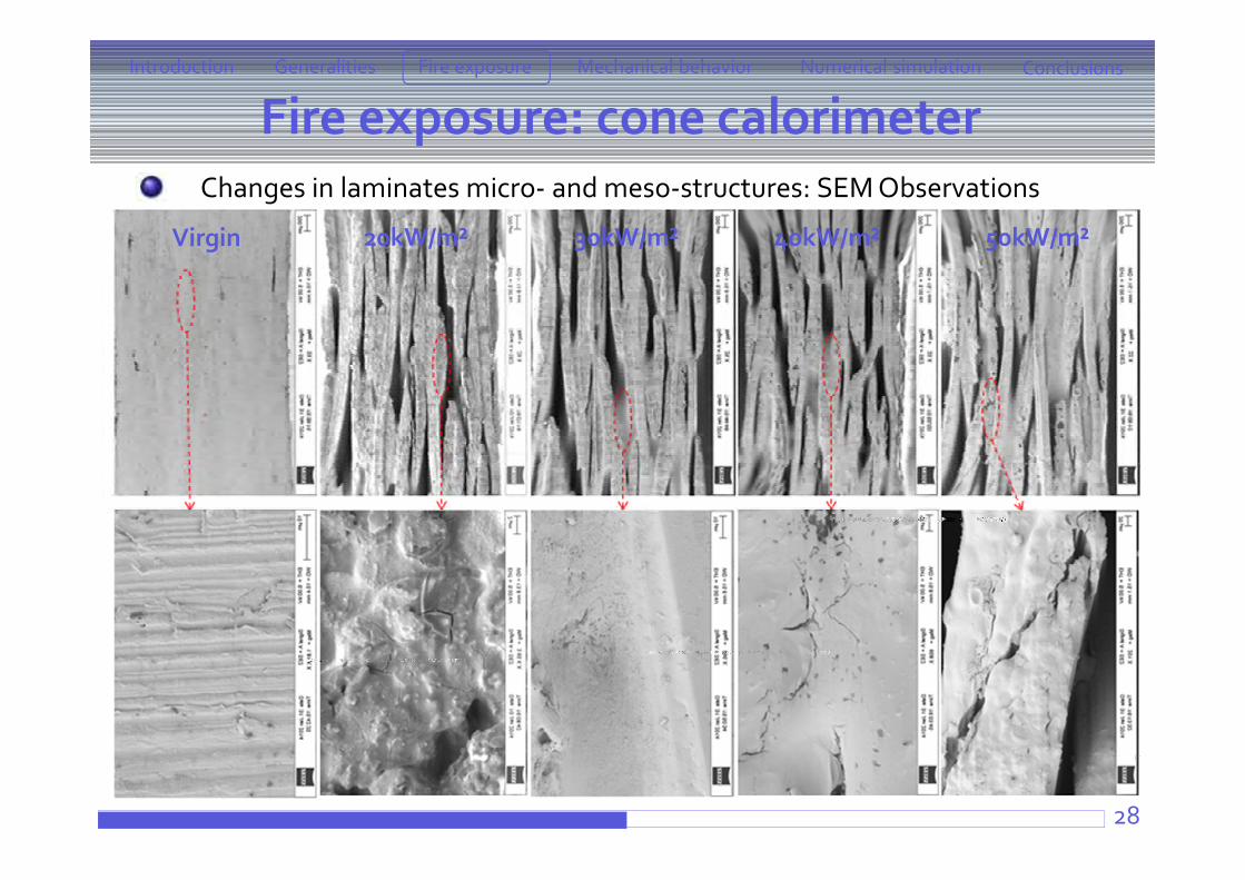
28
Changes in laminates micro- and meso-structures: SEM Observations
Introduction ConclusionsFire exposure Mechanical behaviorGeneralities Numerical simulation
Virgin 20kW/m² 30kW/m² 40kW/m² 50kW/m²
Fire exposure: cone calorimeter
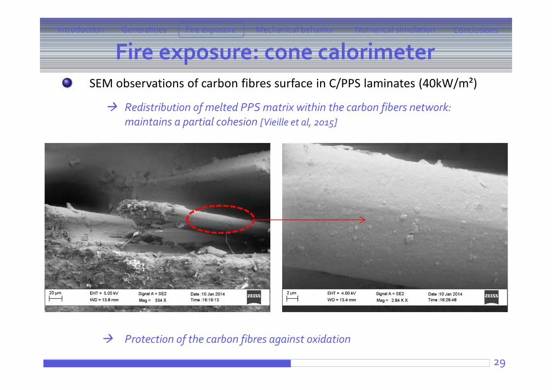
29
SEM observations of carbon fibres surface in C/PPS laminates (40kW/m²)
Redistribution of melted PPS matrix within the carbon fibers network: maintains a partial cohesion [Vieille et al, 2015]
Protection of the carbon fibres against oxidation
Introduction ConclusionsFire exposure Mechanical behaviorGeneralities Numerical simulation
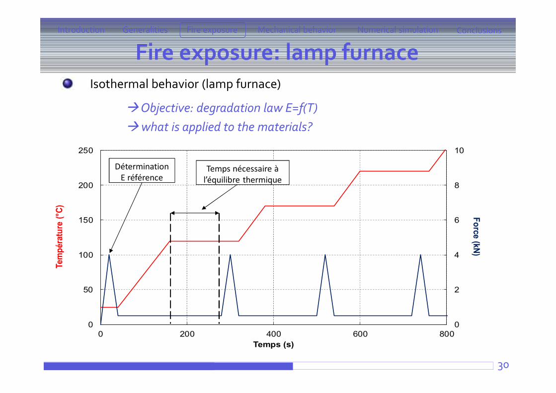
Fire exposure: lamp furnace
30
Isothermal behavior (lamp furnace)
Objective: degradation law E=f(T)what is applied to the materials?
Introduction ConclusionsFire exposure Mechanical behaviorGeneralities Numerical simulation
0
2
4
6
8
10
0
50
100
150
200
250
0 200 400 600 800
Force (kN)
Tem
péra
ture
(°C)
Temps (s)
Détermination E référence
Temps nécessaire à l’équilibre thermique
31
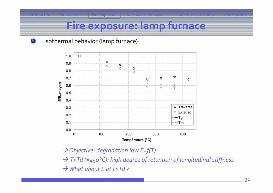
Isothermal behavior (lamp furnace)
Objective: degradation law E=f(T) T<Td (=450°C): high degree of retention of longitudinal stiffnessWhat about E at T>Td ?
Introduction ConclusionsFire exposure Mechanical behaviorGeneralities Numerical simulation
0.0
0.1
0.2
0.3
0.4
0.5
0.6
0.7
0.8
0.9
1.0
0 100 200 300 400
E/E 0
moy
en
Température (°C)
TraverseExtensoTgTm
Fire exposure: lamp furnace
32
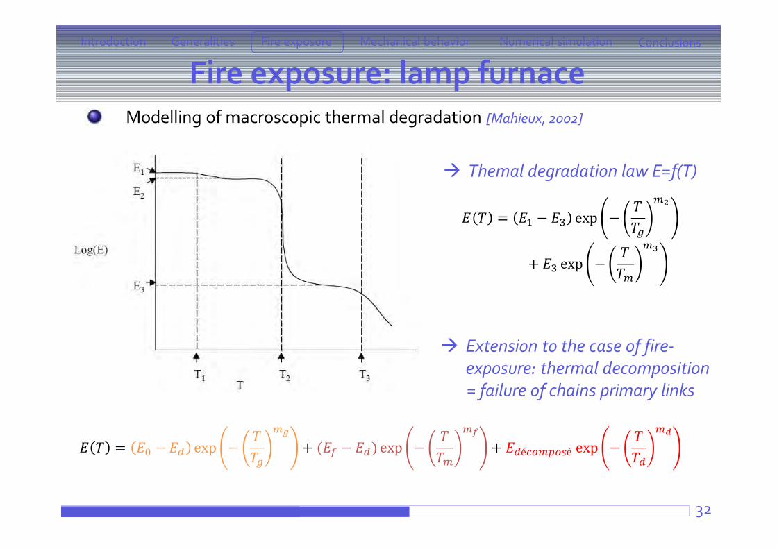
Modelling of macroscopic thermal degradation [Mahieux, 2002]
Introduction ConclusionsFire exposure Mechanical behaviorGeneralities Numerical simulation
Themal degradation law E=f(T)
= − exp −
+ exp −
Extension to the case of fire-exposure: thermal decomposition= failure of chains primary links
= − exp − + ( − ) exp − + é é exp −
Fire exposure: lamp furnace
33
Introduction ConclusionsFire exposure Mechanical behaviorGeneralities Numerical simulation
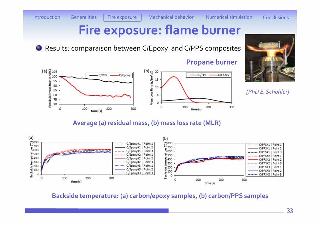
Results: comparaison between C/Epoxy and C/PPS composites
Average (a) residual mass, (b) mass loss rate (MLR)
Backside temperature: (a) carbon/epoxy samples, (b) carbon/PPS samples
Fire exposure: flame burner
Propane burner
[PhD E. Schuhler]
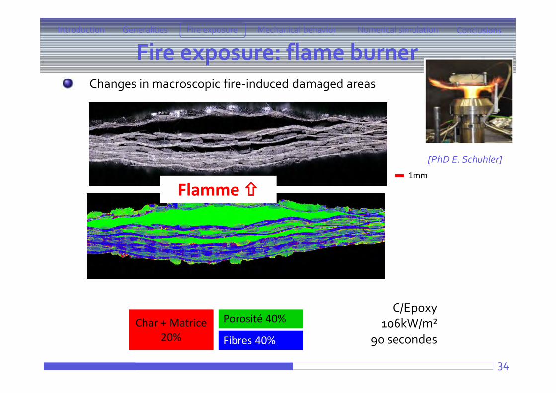
Char + Matrice 20% Fibres 40%
Porosité 40%
Flamme 1mm
Fire exposure: flame burnerIntroduction ConclusionsFire exposure Mechanical behaviorGeneralities Numerical simulation
34
Changes in macroscopic fire-induced damaged areas
[PhD E. Schuhler]
C/Epoxy106kW/m²
90 secondes
Fire exposure: flame burnerIntroduction ConclusionsFire exposure Mechanical behaviorGeneralities Numerical simulation
35
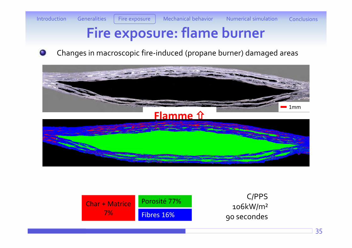
Changes in macroscopic fire-induced (propane burner) damaged areas
1mm
Flamme
Char + Matrice 7% Fibres 16%
Porosité 77% C/PPS106kW/m²
90 secondes
Fire exposure: flame burnerIntroduction ConclusionsFire exposure Mechanical behaviorGeneralities Numerical simulation
36
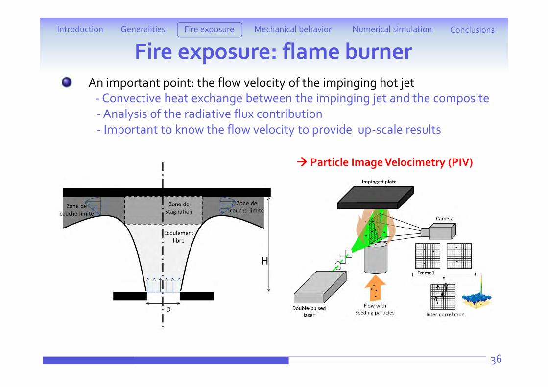
An important point: the flow velocity of the impinging hot jet- Convective heat exchange between the impinging jet and the composite- Analysis of the radiative flux contribution- Important to know the flow velocity to provide up-scale results
H
Particle Image Velocimetry (PIV)
Fire exposure: flame burnerIntroduction ConclusionsFire exposure Mechanical behaviorGeneralities Numerical simulation
37
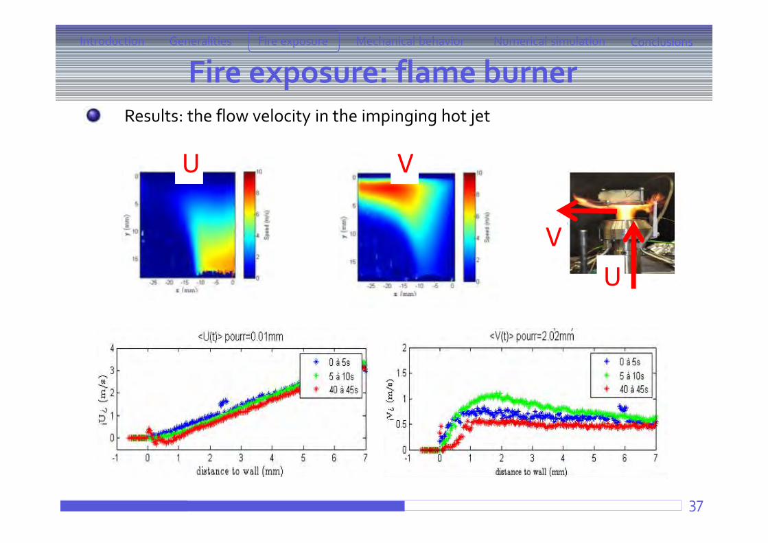
Results: the flow velocity in the impinging hot jet
UV
U V
Fire exposure: flame burnerIntroduction ConclusionsFire exposure Mechanical behaviorGeneralities Numerical simulation
38
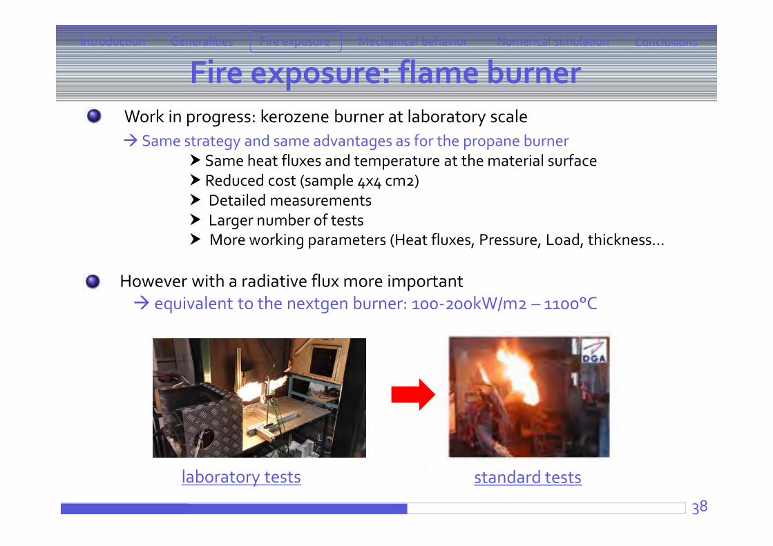
Work in progress: kerozene burner at laboratory scale Same strategy and same advantages as for the propane burner
Same heat fluxes and temperature at the material surface Reduced cost (sample 4x4 cm2) Detailed measurements Larger number of tests More working parameters (Heat fluxes, Pressure, Load, thickness…
standard testslaboratory tests
However with a radiative flux more important equivalent to the nextgen burner: 100-200kW/m2 – 1100°C
Generalities Aeronautics context What materials ? Experimental procedure
Fire exposureCone calorimeterATG + Lamp furnacePropane-flame burner
Mechanical behavior under fire exposurePost-fire testingCombined testing
Numerical simulationCorrelation between temperature distribution and matrix thermal degradation
Conclusions and perspectives39
Introduction ConclusionsFire exposure Mechanical behaviorGeneralities Numerical simulation
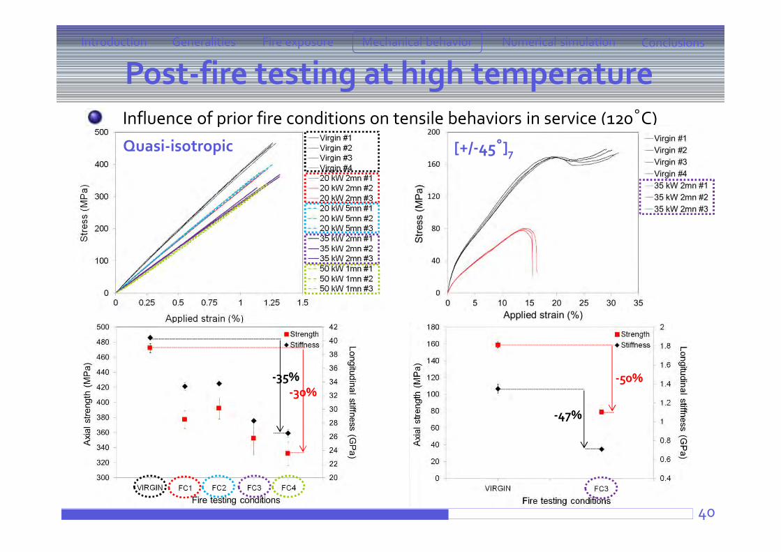
Post-fire testing at high temperature
40
Influence of prior fire conditions on tensile behaviors in service (120°C)
Introduction ConclusionsFire exposure Mechanical behaviorGeneralities Numerical simulation
Quasi-isotropic [+/-45°]7
-35%-30%
-47%
-50%
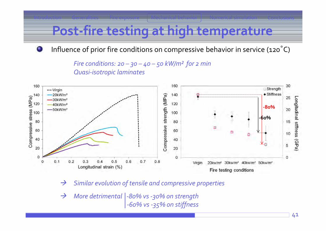
Post-fire testing at high temperature
41
Influence of prior fire conditions on compressive behavior in service (120°C)
Fire conditions: 20 – 30 – 40 – 50 kW/m² for 2 minQuasi-isotropic laminates
Similar evolution of tensile and compressive properties
More detrimental -80% vs -30% on strength-60% vs -35% on stiffness
Introduction ConclusionsFire exposure Mechanical behaviorGeneralities Numerical simulation
-80%
-60%
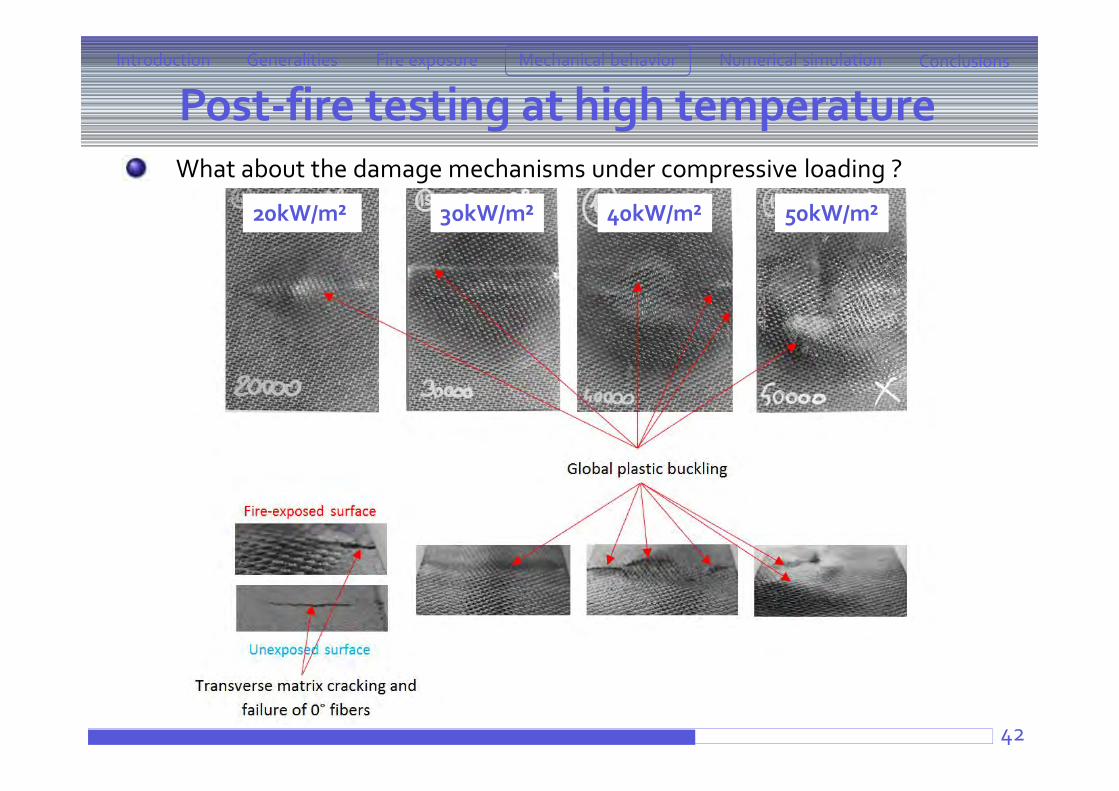
Post-fire testing at high temperature
42
What about the damage mechanisms under compressive loading ?
Introduction ConclusionsFire exposure Mechanical behaviorGeneralities Numerical simulation
20kW/m² 30kW/m² 40kW/m² 50kW/m²
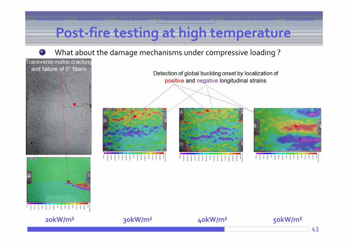
Post-fire testing at high temperature
43
What about the damage mechanisms under compressive loading ?
Introduction ConclusionsFire exposure Mechanical behaviorGeneralities Numerical simulation
20kW/m² 30kW/m² 40kW/m² 50kW/m²
Post-fire testing at high temperature
44
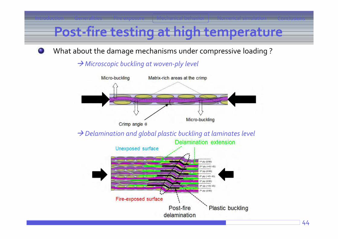
What about the damage mechanisms under compressive loading ?
Microscopic buckling at woven-ply level
Delamination and global plastic buckling at laminates level
Introduction ConclusionsFire exposure Mechanical behaviorGeneralities Numerical simulation
Post-fire testing at high temperature
45
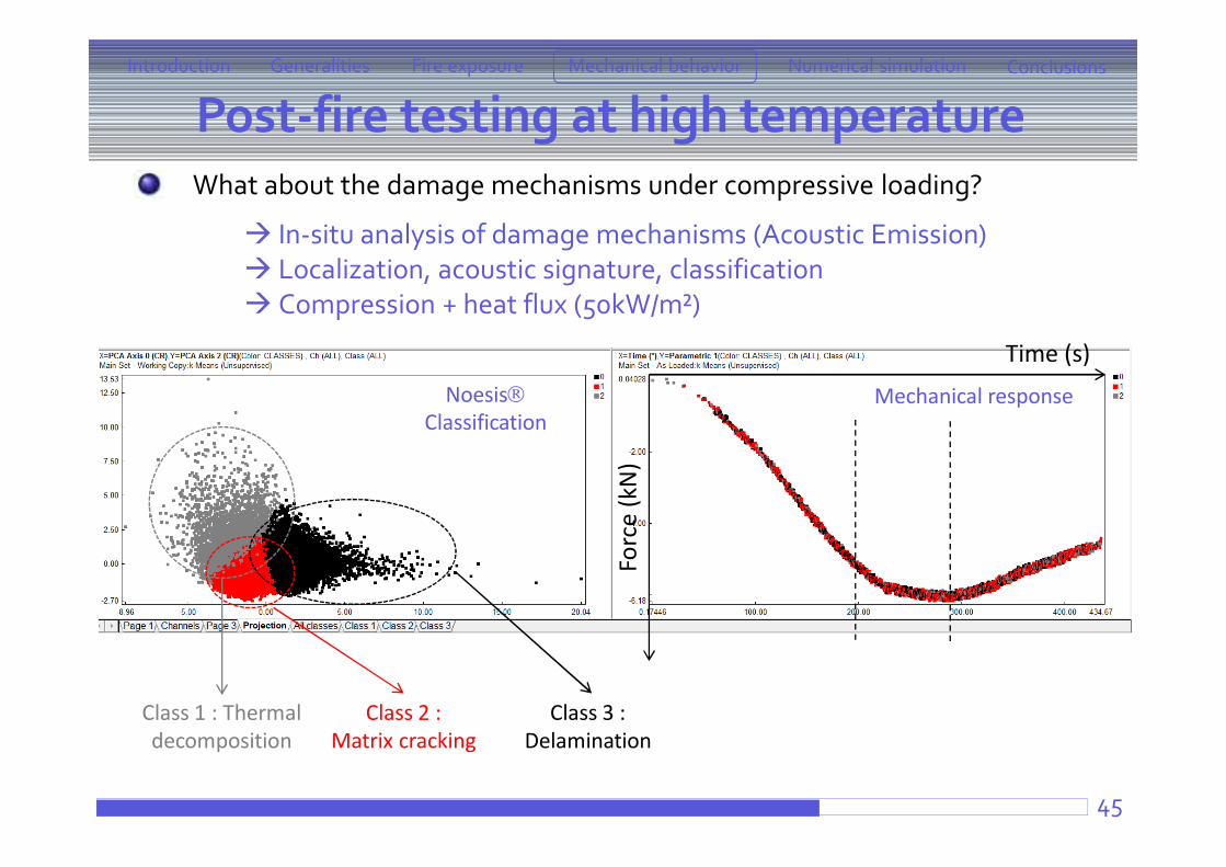
What about the damage mechanisms under compressive loading?
In-situ analysis of damage mechanisms (Acoustic Emission) Localization, acoustic signature, classification Compression + heat flux (50kW/m²)
Introduction ConclusionsFire exposure Mechanical behaviorGeneralities Numerical simulation
Forc
e (k
N)
Time (s)
Class 1 : Thermal decomposition
Class 2 :Matrix cracking
NoesisClassification
Mechanical response
Class 3 :Delamination
Combined testing
46
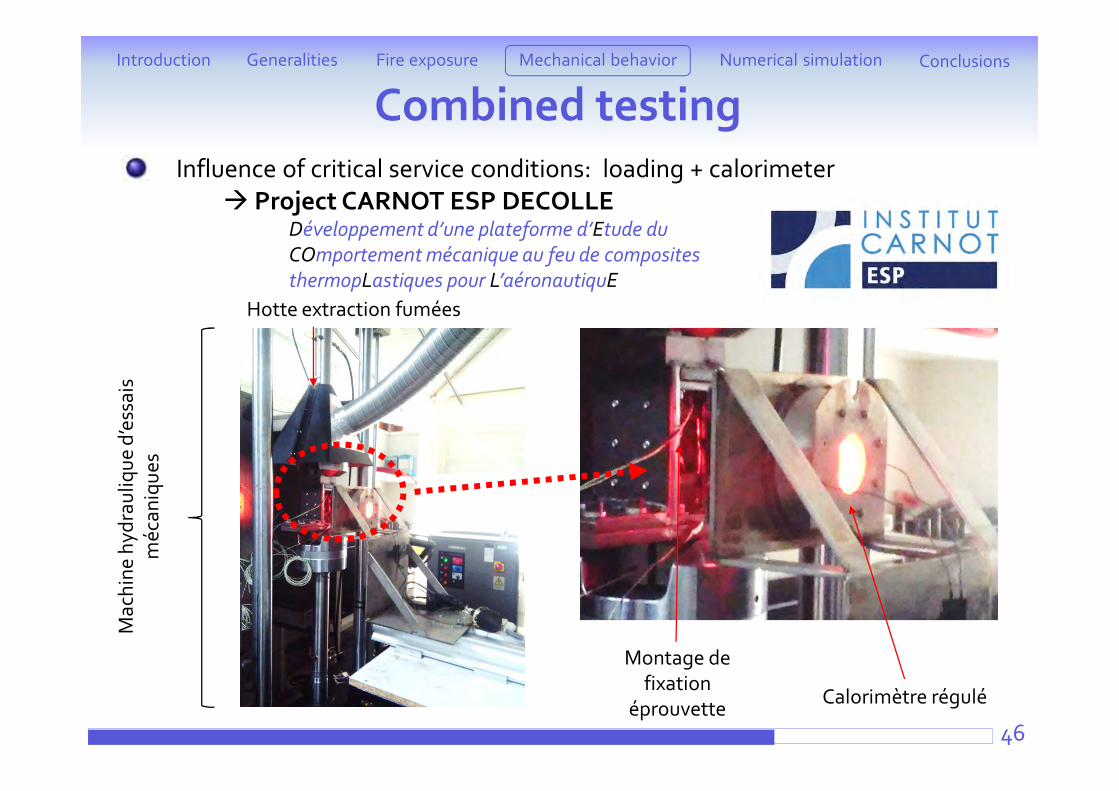
Influence of critical service conditions: loading + calorimeter Project CARNOT ESP DECOLLE
Développement d’une plateforme d’Etude du COmportement mécanique au feu de composites thermopLastiques pour L’aéronautiquE
Introduction ConclusionsFire exposure Mechanical behaviorGeneralities Numerical simulation
Mac
hine
hyd
raul
ique
d’e
ssai
s m
écan
ique
s
Hotte extraction fumées
Calorimètre régulé
Montage de fixation
éprouvette
Combined testing
47
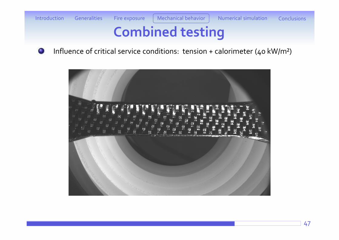
Influence of critical service conditions: tension + calorimeter (40 kW/m²)
Introduction ConclusionsFire exposure Mechanical behaviorGeneralities Numerical simulation
Combined testing
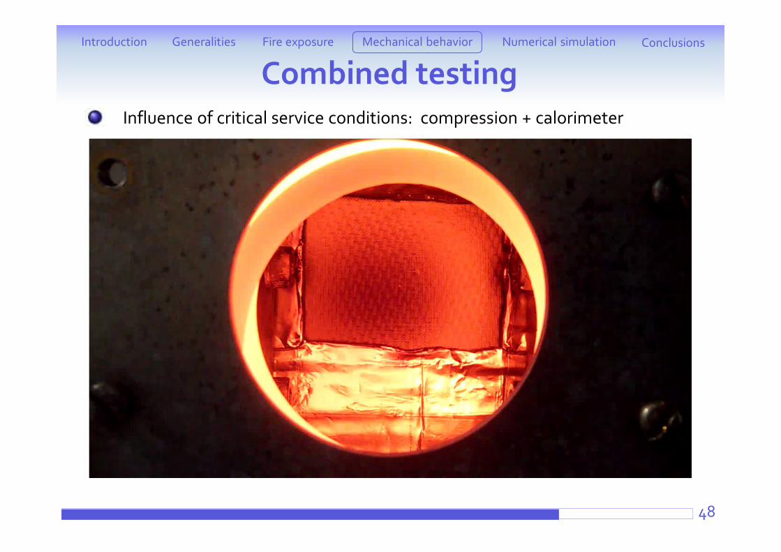
48
Influence of critical service conditions: compression + calorimeter
Introduction ConclusionsFire exposure Mechanical behaviorGeneralities Numerical simulation
Combined testing
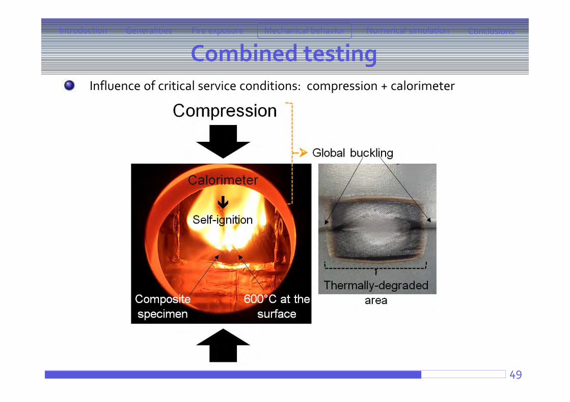
49
Influence of critical service conditions: compression + calorimeter
Introduction ConclusionsFire exposure Mechanical behaviorGeneralities Numerical simulation
Combined testing
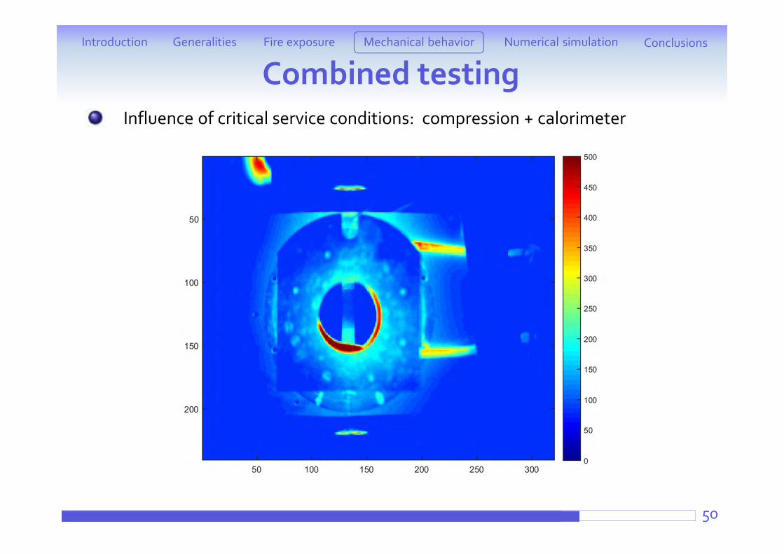
50
Influence of critical service conditions: compression + calorimeter
Introduction ConclusionsFire exposure Mechanical behaviorGeneralities Numerical simulation
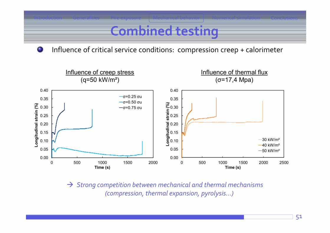
Influence of creep stress (q=50 kW/m²)
Influence of thermal flux (σ=17,4 Mpa)
Strong competition between mechanical and thermal mechanisms (compression, thermal expansion, pyrolysis…)
0.00
0.05
0.10
0.15
0.20
0.25
0.30
0.35
0.40
0 500 1000 1500 2000 2500Lo
ngitu
dina
l str
ain
(%)
Time (s)
30 kW/m²40 kW/m²50 kW/m²
0.00
0.05
0.10
0.15
0.20
0.25
0.30
0.35
0.40
0 500 1000 1500 2000
Long
itudi
nal s
trai
n (%
)
Time (s)
σ=0.25 σuσ=0.50 σuσ=0.75 σu
Combined testingIntroduction ConclusionsFire exposure Mechanical behaviorGeneralities Numerical simulation
Influence of critical service conditions: compression creep + calorimeter
51
Combined testingIntroduction ConclusionsFire exposure Mechanical behaviorGeneralities Numerical simulation
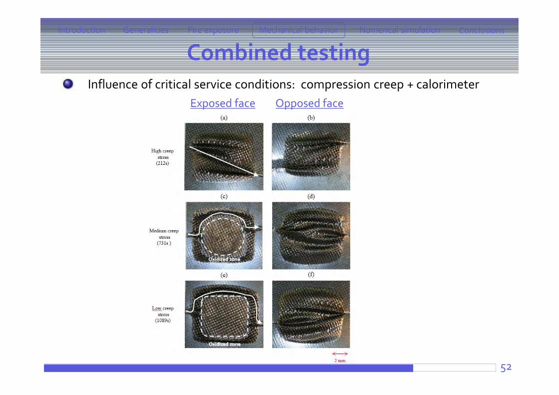
Influence of critical service conditions: compression creep + calorimeter
52
Exposed face Opposed face
Combined testingIntroduction ConclusionsFire exposure Mechanical behaviorGeneralities Numerical simulation
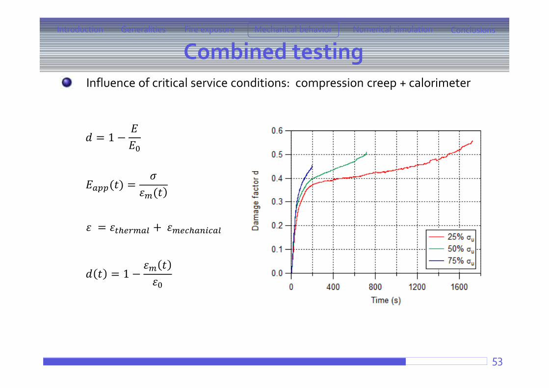
Influence of critical service conditions: compression creep + calorimeter
53
= +
( ) =( )
= 1 −
= 1 −
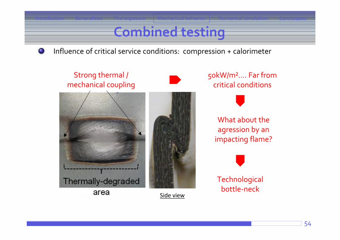
Strong thermal / mechanical coupling
What about the agression by an
impacting flame?
Technologicalbottle-neck
50kW/m²…. Far fromcritical conditions
Side view
Combined testingIntroduction ConclusionsFire exposure Mechanical behaviorGeneralities Numerical simulation
Influence of critical service conditions: compression + calorimeter
54
Combined testingIntroduction ConclusionsFire exposure Mechanical behaviorGeneralities Numerical simulation
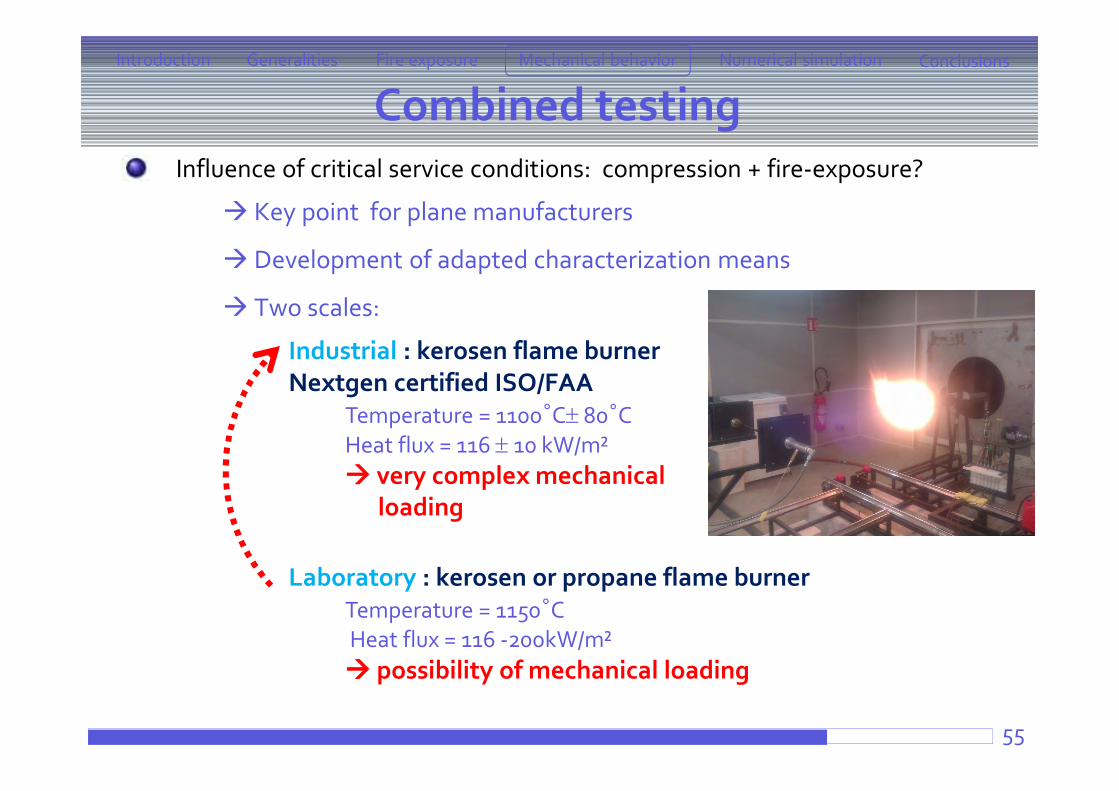
Influence of critical service conditions: compression + fire-exposure?
Key point for plane manufacturers
Development of adapted characterization means
Two scales:
Industrial : kerosen flame burnerNextgen certified ISO/FAA
Temperature = 1100°C 80°CHeat flux = 116 10 kW/m² very complex mechanical
loading
Laboratory : kerosen or propane flame burnerTemperature = 1150°CHeat flux = 116 -200kW/m² possibility of mechanical loading
55
Generalities Aeronautics context What materials ? Experimental procedure
Fire exposure Cone calorimeter
ATG + Lamp furnacePropane-flame burner
Mechanical behavior under fire exposurePost-fire testingCombined testing
Numerical simulationCorrelation between temperature distribution and matrix thermal degradation
Conclusions and perspectives56
Introduction ConclusionsFire exposure Mechanical behaviorGeneralities Numerical simulation
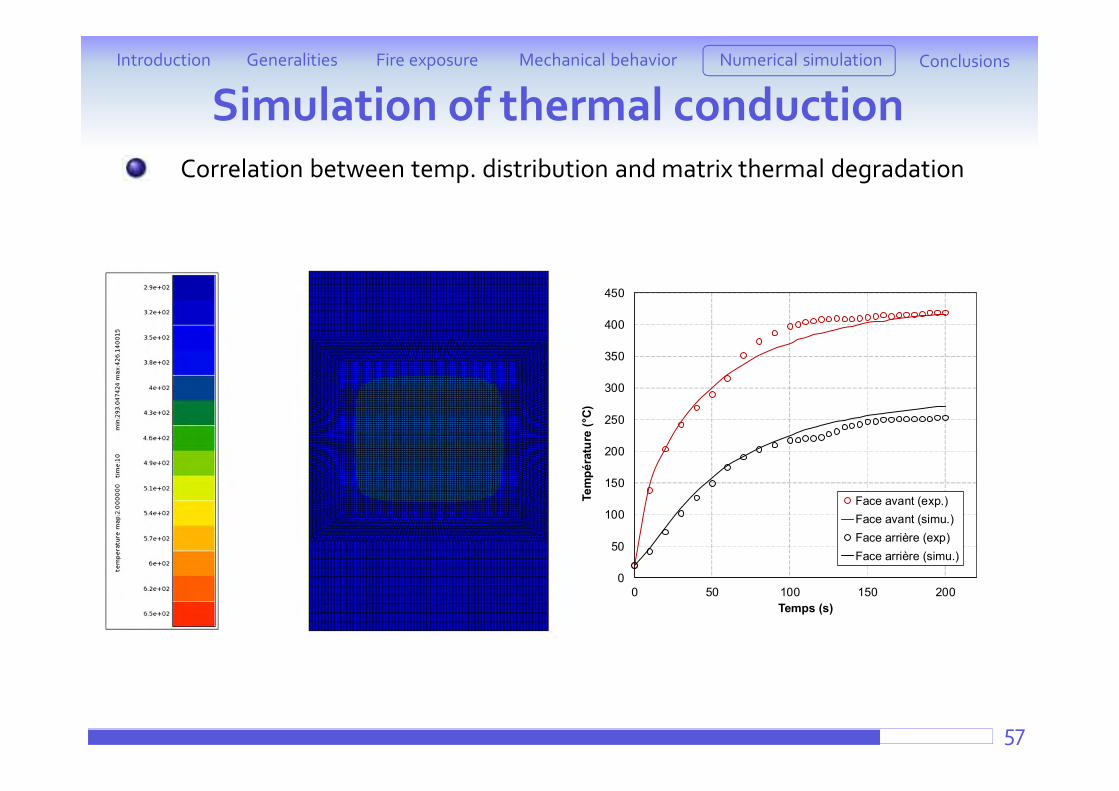
Simulation of thermal conduction
57
Correlation between temp. distribution and matrix thermal degradation
Introduction ConclusionsFire exposure Mechanical behaviorGeneralities Numerical simulation
0
50
100
150
200
250
300
350
400
450
0 50 100 150 200Te
mpé
ratu
re (°
C)
Temps (s)
Face avant (exp.)Face avant (simu.)Face arrière (exp)Face arrière (simu.)
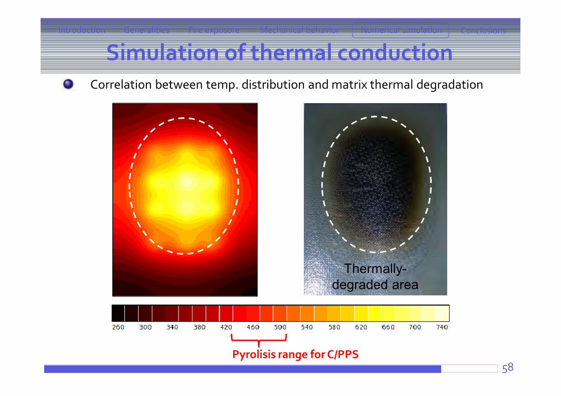
Simulation of thermal conduction
58
Correlation between temp. distribution and matrix thermal degradation
Introduction ConclusionsFire exposure Mechanical behaviorGeneralities Numerical simulation
Thermally-degraded area
Pyrolisis range for C/PPS
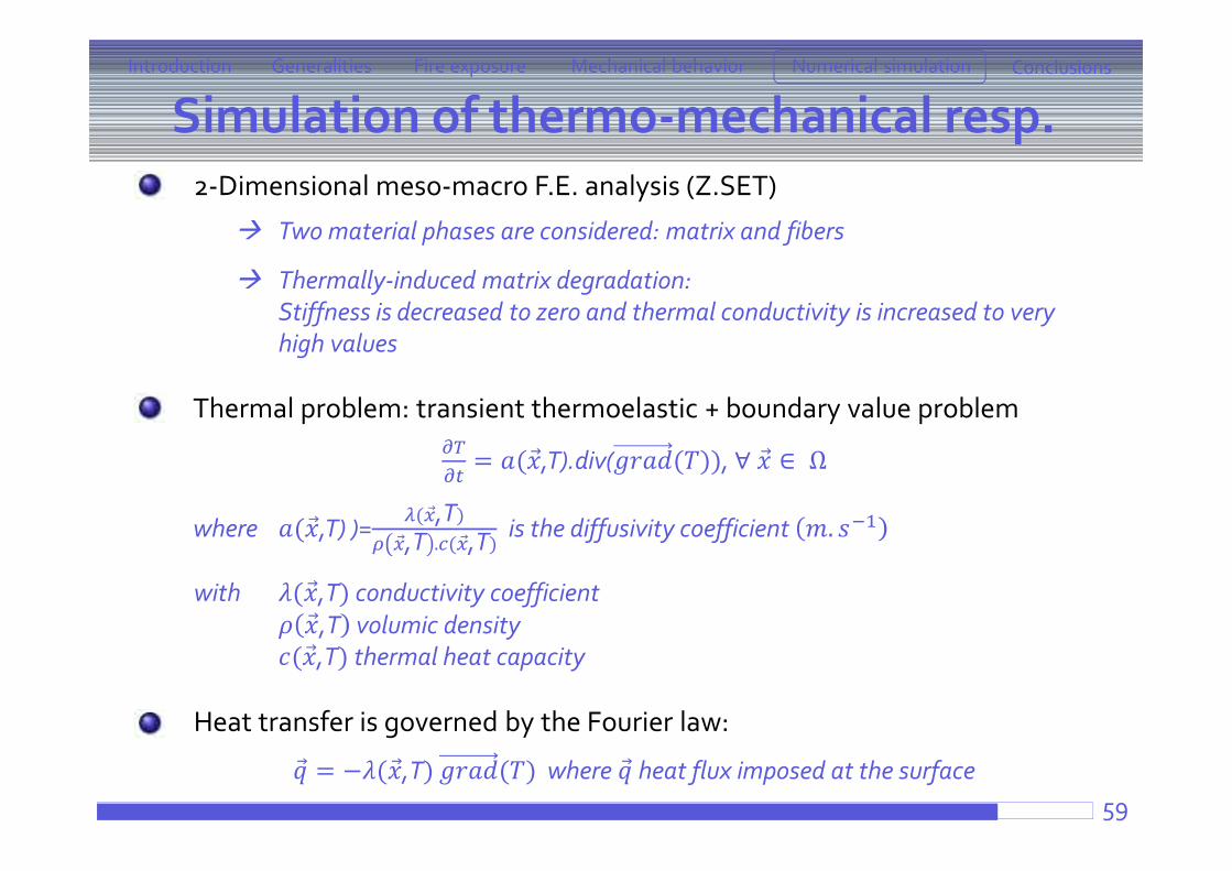
Simulation of thermo-mechanical resp.
59
2-Dimensional meso-macro F.E. analysis (Z.SET)
Two material phases are considered: matrix and fibers
Thermally-induced matrix degradation: Stiffness is decreased to zero and thermal conductivity is increased to very high values
Thermal problem: transient thermoelastic + boundary value problem
= ( ,T).div( ( )), ∀ ∈ Ω
where ( ,T) )= ( ,T),T . ( ,T)
is the diffusivity coefficient .
with ( ,T) conductivity coefficient,T volumic density
( ,T) thermal heat capacity
Heat transfer is governed by the Fourier law:
= − ( ,T) ( ) where heat flux imposed at the surface
Introduction ConclusionsFire exposure Mechanical behaviorGeneralities Numerical simulation
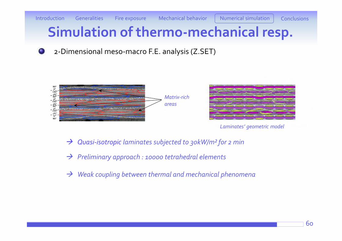
Quasi-isotropic laminates subjected to 30kW/m² for 2 min
Preliminary approach : 10000 tetrahedral elements
Weak coupling between thermal and mechanical phenomena
Matrix-richareas
Laminates’ geometric model
Simulation of thermo-mechanical resp.Introduction ConclusionsFire exposure Mechanical behaviorGeneralities Numerical simulation
2-Dimensional meso-macro F.E. analysis (Z.SET)
60
Simulation of thermo-mechanical resp.
61
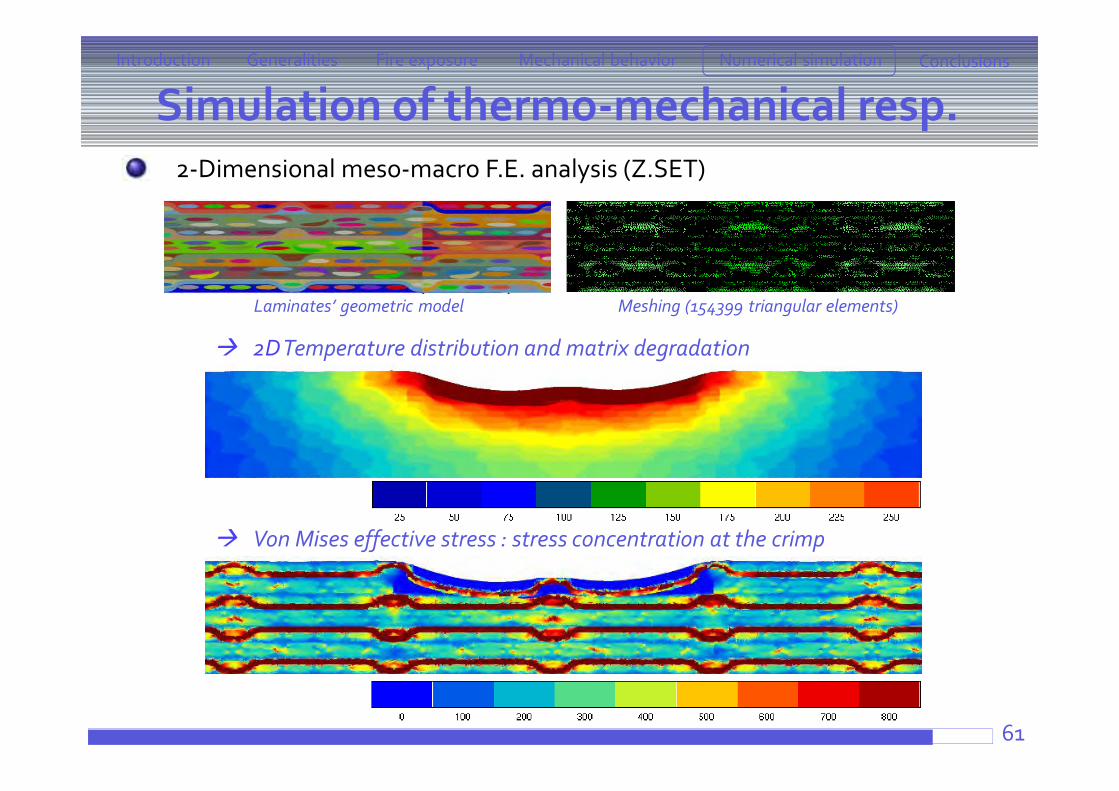
2-Dimensional meso-macro F.E. analysis (Z.SET)
2D Temperature distribution and matrix degradation
Von Mises effective stress : stress concentration at the crimp
Introduction ConclusionsFire exposure Mechanical behaviorGeneralities Numerical simulation
Laminates’ geometric model Meshing (154399 triangular elements)
Generalities Aeronautics context What materials ? Experimental procedure
Fire exposure Cone calorimeter
ATG + Lamp furnacePropane-flame burner
Post-fire behavior at high-temperatureTensile testsCompressive tests
Numerical simulationCorrelation between temperature distribution and matrix thermal degradation
Conclusions and perspectives62
Introduction ConclusionsFire exposure Mechanical behaviorGeneralities Numerical simulation
Conclusions and perspectives
63
Introduction ConclusionsFire exposure Mechanical behaviorGeneralities Numerical simulation
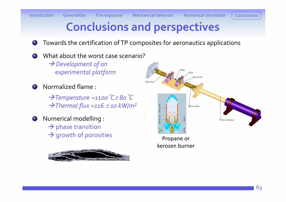
Towards the certification of TP composites for aeronautics applications
What about the worst case scenario? Development of an
experimental platform
Normalized flame :
Temperature =1100°C 80°CThermal flux =116 10 kW/m²
Numerical modelling : phase transition growth of porosities Propane or
kerozen burner

Thanks for your attention !Questions ?