Notice Horloge mère Microquartz 6 - BODET Time...Brancher les circuits de programmation sur le...
24
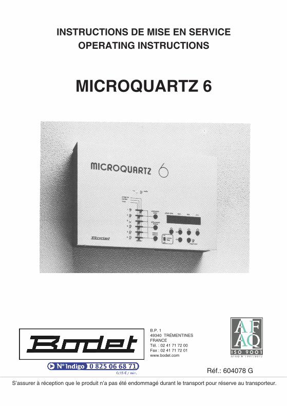
INSTRUCTIONS DE MISE EN SERVICE OPERATING INSTRUCTIONS MICROQUARTZ 6 S’assurer à réception que le produit n’a pas été endommagé durant le transport pour réserve au transporteur. B.P. 1 49340 TRÉMENTINES FRANCE Tél. : 02 41 71 72 00 Fax : 02 41 71 72 01 www.bodet.com Réf.: 604078 G
Transcript of Notice Horloge mère Microquartz 6 - BODET Time...Brancher les circuits de programmation sur le...
INSTRUCTIONS DE MISE EN SERVICEOPERATING INSTRUCTIONS
MICROQUARTZ 6
S’assurer à réception que le produit n’a pas été endommagé durant le transport pour réserve au transporteur.
B.P. 149340 TRÉMENTINESFRANCETél. : 02 41 71 72 00Fax : 02 41 71 72 01www.bodet.com
Réf.: 604078 G
RECOMMANDATIONS GÉNÉRALES
� S’assurer, à la réception, que l’appareil n’a pas été endommagé dans le transport,
� Avant la mise en service, lire le mode d’emploi et se familiariser avec les manipulations,
� Lorsque la batterie est branchée, éviter toute manipulation et branchement à l’intérieur del’appareil,
� Changer la batterie 12V tous les 4 ans en conservant l’alimentation secteur afin de ne pasperdre la programmation.
GENERAL RECOMMENDATIONS
� Upon receipt of the equipment make sure that it has not been damaged during transport,
� Before setting in operation read the instructions manual and get familiarized with itscontrols,
� After connecting the battery avoid any operation or connection inside the appliance,
� Change de 12 V battery every 4 years while keeping the mains on in order to avoid losingthe programming.
CONSERVER CE LIVRET DANS L’APPAREILSTORE THIS BOOKLET INSIDE THE UNIT
2
Table des matières
2 - RECOMMANDATIONS GÉNÉRALES
3 - DESCRIPTIF
4 - CARACTÉRISTIQUES TECHNIQUES
5 - INSTALLATION
6 - PROGRAMMATION DE LADISTRIBUTION HORAIRE
8 - MISE À L’HEURE
10 - PROGRAMMATION DES CIRCUITS
12 - PROGRAMME TEST
Index
2 - GENERAL RECOMMENDATIONS
14 - TECHNICAL CHARACTERISTICS
15 - INSTALLATION
16 - SET UP OF CLOCK SYSTEM
18 - SETTING THE TIME
20 - PROGRAMMING OF THECHANNELS
22 - TEST PROGRAMME
DESCRIPTIF
3
1
2
3
456789101112131415
16
17
18
19
20 21 22 23 24 25
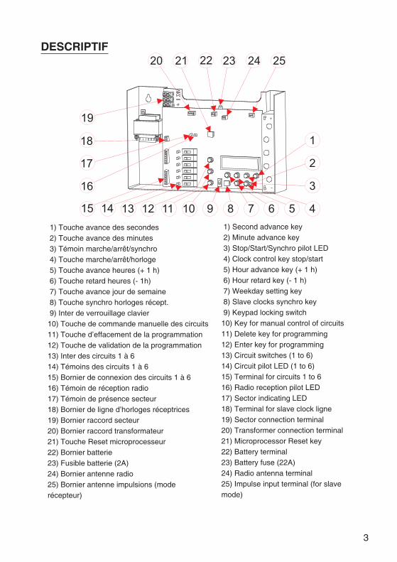
1) Second advance key2) Minute advance key3) Stop/Start/Synchro pilot LED4) Clock control key stop/start5) Hour advance key (+ 1 h)6) Hour retard key (- 1 h)7) Weekday setting key8) Slave clocks synchro key9) Keypad locking switch10) Key for manual control of circuits11) Delete key for programming12) Enter key for programming13) Circuit switches (1 to 6)14) Circuit pilot LED (1 to 6)15) Terminal for circuits 1 to 616) Radio reception pilot LED17) Sector indicating LED18) Terminal for slave clock ligne19) Sector connection terminal20) Transformer connection terminal21) Microprocessor Reset key22) Battery terminal23) Battery fuse (22A)24) Radio antenna terminal25) Impulse input terminal (for slavemode)
1) Touche avance des secondes2) Touche avance des minutes3) Témoin marche/arrêt/synchro4) Touche marche/arrêt/horloge5) Touche avance heures (+ 1 h)6) Touche retard heures (- 1h)7) Touche avance jour de semaine8) Touche synchro horloges récept.9) Inter de verrouillage clavier
10) Touche de commande manuelle des circuits11) Touche d’effacement de la programmation12) Touche de validation de la programmation13) Inter des circuits 1 à 614) Témoins des circuits 1 à 615) Bornier de connexion des circuits 1 à 616) Témoin de réception radio17) Témoin de présence secteur18) Bornier de ligne d’horloges réceptrices19) Bornier raccord secteur20) Bornier raccord transformateur21) Touche Reset microprocesseur22) Bornier batterie23) Fusible batterie (2A)24) Bornier antenne radio25) Bornier antenne impulsions (moderécepteur)
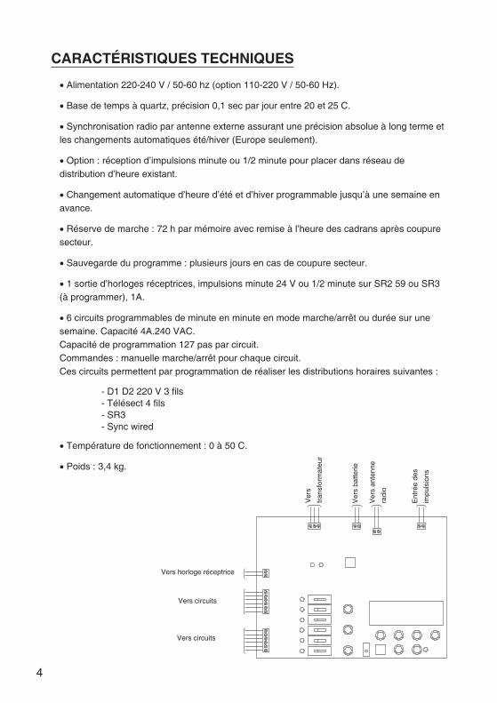
CARACTÉRISTIQUES TECHNIQUES
� Alimentation 220-240 V / 50-60 hz (option 110-220 V / 50-60 Hz).
� Base de temps à quartz, précision 0,1 sec par jour entre 20 et 25 C.
� Synchronisation radio par antenne externe assurant une précision absolue à long terme etles changements automatiques été/hiver (Europe seulement).
� Option : réception d’impulsions minute ou 1/2 minute pour placer dans réseau dedistribution d’heure existant.
� Changement automatique d’heure d’été et d’hiver programmable jusqu’à une semaine enavance.
� Réserve de marche : 72 h par mémoire avec remise à l’heure des cadrans après coupuresecteur.
� Sauvegarde du programme : plusieurs jours en cas de coupure secteur.
� 1 sortie d’horloges réceptrices, impulsions minute 24 V ou 1/2 minute sur SR2 59 ou SR3(à programmer), 1A.
� 6 circuits programmables de minute en minute en mode marche/arrêt ou durée sur unesemaine. Capacité 4A.240 VAC.Capacité de programmation 127 pas par circuit.Commandes : manuelle marche/arrêt pour chaque circuit.Ces circuits permettent par programmation de réaliser les distributions horaires suivantes :
- D1 D2 220 V 3 fils- Télésect 4 fils- SR3- Sync wired
� Température de fonctionnement : 0 à 50 C.
� Poids : 3,4 kg.
4
Vers horloge réceptrice
Vers circuits
Vers circuits
Ver
s
tran
sfor
mat
eur
Ver
sba
tterie
Ver
san
tenn
e
radi
o
Ent
rée
des
impu
lsio
ns
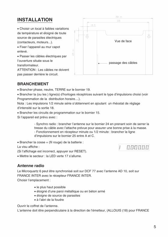
INSTALLATION
� Choisir un local à faibles variationsde température et éloigné de toutesource de parasites électriques(contacteurs, moteurs...).
� Fixer l’appareil au mur capotenlevé.
� Passer les câbles électriques parl’ouverture située sous letransformateur.ATTENTION : Les câbles ne doiventpas passer derrière le circuit.
BRANCHEMENT� Brancher phase, neutre, TERRE sur le bornier 19.
� Brancher la (ou les ) ligne(s) d’horloges réceptrices suivant le type d’impulsions choisi (voirProgrammation de la distribution horaire....).Nota : Les impulsions 1/2 minute série s’obtiennent en ajoutant un rhéostat de réglaged’intensité sur la sortie 18.
� Brancher les circuits de programmation sur le bornier 15.Si l’appareil est prévu avec :
- Synchro radio : brancher l’antenne sur le bornier 24 en prenant soin de serrer latresse du câble avec l’attache prévue pour assurer une bonne prise à la masse.- Fonctionnement en récepteur minute ou 1/2 minute : brancher la ligned’impulsions sur le bornier 25 entre A et C.
� Brancher la cosse + (fil rouge) de la batterie :La visu affiche :(Si l’affichage est incorrect, appuyer sur RESET).
� Mettre le secteur : la LED verte 17 s’allume.
Antenne radioLe Microquartz 6 peut être synchronisé soit sur DCF 77 avec l’antenne AD 10, soit surFRANCE INTER avec le récepteur FRANCE INTER.Choisir l’emplacement :
� le plus haut possible� éloigné d’une paroi métallique ou en béton armé� éloigne de source de parasites� à l’abri de la foudre
Ouvrir le coffret de l’antenne.L’antenne doit être perpendiculaire à la direction de l’émetteur, (ALLOUIS (18) pour FRANCE
5
Vue de face
passage des câbles
INTER, MAINFLINGEN (RFA) pour DCF 77), le presse étoupe vers le basL’orientation est bonne si :
� les voyants se trouvant dans l’antenne et sur le Microquartz clignotent une foispar seconde.� Le son à l’écouteur est net et s’il disparaît une fois par seconde (antenne AD10).
Fixer l’antenne sur son support.Fermer l’antenne en faisant attention à l’étanchéité de la boîte.Nota : L’horloge se synchronise automatiquement après 5 à 15 minutes, toutefois en casd’environnement difficile la synchronisation peut nécessiter jusqu’à 24 heures.
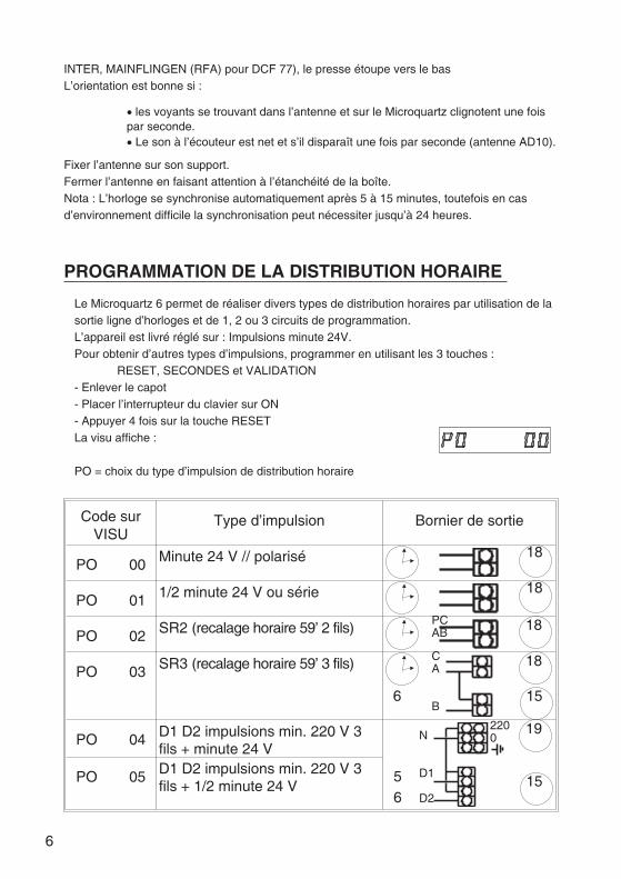
PROGRAMMATION DE LA DISTRIBUTION HORAIRE
Le Microquartz 6 permet de réaliser divers types de distribution horaires par utilisation de lasortie ligne d’horloges et de 1, 2 ou 3 circuits de programmation.L’appareil est livré réglé sur : Impulsions minute 24V.Pour obtenir d’autres types d’impulsions, programmer en utilisant les 3 touches :
RESET, SECONDES et VALIDATION- Enlever le capot- Placer l’interrupteur du clavier sur ON- Appuyer 4 fois sur la touche RESETLa visu affiche :
PO = choix du type d’impulsion de distribution horaire
Code surVISU
Type d’impulsion Bornier de sortie
PO 00 Minute 24 V // polarisé
PO 01 1/2 minute 24 V ou série
PO 02 SR2 (recalage horaire 59’ 2 fils)
PO 03 SR3 (recalage horaire 59’ 3 fils)
PO 04 D1 D2 impulsions min. 220 V 3fils + minute 24 V
PO 05 D1 D2 impulsions min. 220 V 3fils + 1/2 minute 24 V
6
18
18
18PCAB
CA
B156
18
1556
192200N
D1
D2
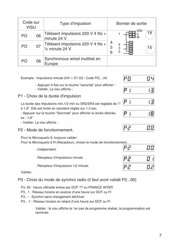
Code surVISU
Type d’impulsion Bornier de sortie
PO 06 Télésect impulsions 220 V 4 fils +minute 24 V
PO 07 Télésect impulsions 220 V 4 fils +½ minute 24 V
PO 08 Synchronous wired inutilisé enEurope
Exemple : Impulsions minute 24V + D1 D2 : Code PO....04.
- Appuyer 4 fois sur la touche “seconde” pour afficher :- Valider. La visu affiche :
P1 - Choix de la durée d’impulsion
La durée des impulsions min,1/2 min ou SR2/SR3 est réglable de 1"à 1.8”. Elle est livrée en standard réglée sur 1,3 sec.- Appuyer sur la touche “Seconde” pour afficher la durée désirée,ex : 1,8"- Valider. La visu affiche :
P2 - Mode de fonctionnement.
Pour le Microquartz 6, toujours valider.Pour le Microquartz 6 R (Récepteur), choisir le mode de fonctionnement :
. Indépendant.
. Récepteur d’impulsions minute.
. Récepteur d’impulsions 1/2 minute.
Valider.
P3 - Choix du mode de synchro radio (il faut avoir validé P2...00)
P3..00 : Heure officielle émise par DCF 77 ou FRANCE INTERP3.. 1 : Réseau horaire en avance d’une heure sur DCF ou FIP3.. - : Synchro sans changement été/hiverP3.. -1 : Réseau horaire en retard d’une heure sur DCF ou FI
Valider : la visu affiche le 1er pas de programme réalisé, la programmation estterminée.
7
15456
1922001
432
Contrôle du programme
- Appuyer successivement sur la touche VALIDATION pour afficher les pas de programme.
Sortie du programme
- Appuyer sur la touche RESET. La visu affiche :Nota : Si l’on appuie une nouvelle fois sur la touche RESET on entre dans le programmeTEST (voir P.11). Pour revenir au programme DISTRIBUTION HORAIRE, démarrerl’horloge puis l’arrêter (touche Start/Stop) puis appuyer 4 fois sur la touche RESET.
MISE À L’HEURE
Mise à l’heure de la distribution horaire
Si la distribution horaire est programmée pour commander 2 réseaux de réceptricesséparés, la mise à l’heure de chaque réseau se fait de manière indépendante pourpermettre le recalage de l’un par rapport à l’autre.
- Réseaux Minute 24 V, 1/2 minute, SR2/SR3
. Mettre toutes les réceptrices à la même heure.
. Enlever le capot du Microquartz.
. Placer l’interrupteur clavier sur ON.
. Arrêter l’horloge en appuyant sur la touche Stop/Start le témoin rouge s’allume.
. Mettre le Microquartz à l’heure indiquée par les réceptrices à l’aide des touches + 1 h,- 1 h, min.. Appuyer sur la touche Stop/Start. Le témoin rouge s’éteint.. Appuyer immédiatement sur la touche “Synchro” (8). Les réceptrices sont synchronisées.. Mettre l’interrupteur clavier sur OFF.
- Réseaux D1 D2, Telesect
Placer l’interrupteur C 6 (13) en position programme puis procéder comme ci-dessus.. Remettre l’interrupteur C6 (13) en position normal.
Mise à l’heure du Microquartz
- Mettre l’interrupteur clavier sur ON.- Arrêter l’horloge en appuyant sur la touche STOP/START la LED rouge (3) s’allume.- Mettre l’horloge au jour et à l’heure exacte à l’aide des touches jour, + 1 h, - 1 h, min.- Au “TOP” horaire appuyer sur Start/Stop. Le témoin rouge s’éteint. Les secondes
8
fonctionnent.- Mettre l’interrupteur clavier sur OFF.Les horloges réceptrices se synchroniseront automatiquement soit par rattrapage (LEDclignote) soit par attente si elles sont en avance de moins d’une heure. Le cycle derattrapage est sur 24 h.
Nota : Il est possible de contrôler l’heure des réceptrices à tout moment :
- pour le 24 V, distribution Min/1/2, le SR2/SR3 : en appuyant sur la toucheVALID.- pour le D1 D2 et le Télésect : en plaçant l’interrupteur du circuit 6 (13) en modeprogramme et en appuyant sur la touche VALID.
Changement d’heure Été/Hiver
Le Microquartz permet d’effectuer le changement d’heure Été/Hiver, soit instantanément,soit pré-programmé.
� Changement instantané :
- Mettre l’interrupteur clavier sur ON- Appuyer sur la touche + 1 h pour l’heure d’été ou - 1 h pour l’heure d’hiver.- Remettre l’interrupteur clavier sur OFF.
� Changement programmé
- Mettre l’interrupteur verrouillage clavier sur ON.- Appuyer sur la touche + 1 h (été) ou - 1 h (hiver) et la maintenir 5 secondes.La visu affiche :- Entrer le jour, heure, minute du changement d’heure.Ex : Dimanche 03 h 00.La visu clignote .- Valider. La visu affiche de nouveau l’heure normale.- Replacer l’interrupteur clavier sur OFF.
Pour vérifier l’heure du changement programmée, procéder comme ci-dessus : le jour etl’heure programmés s’afficheront sur la visu.
9
PROGRAMMATION DES CIRCUITS
Les 6 circuits peuvent être programmés en mode DUREE (sonneries) ou en modeMARCHE/ARRET.
Pour programmer un circuit :
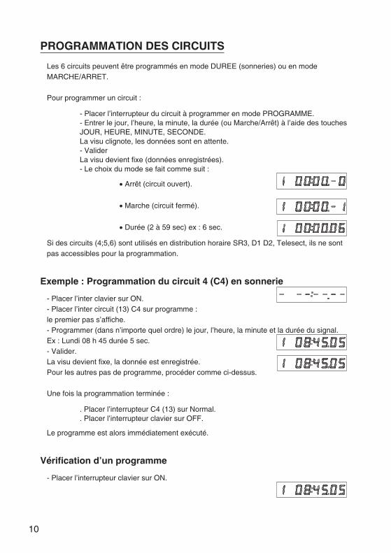
- Placer l’interrupteur du circuit à programmer en mode PROGRAMME.- Entrer le jour, l’heure, la minute, la durée (ou Marche/Arrêt) à l’aide des touchesJOUR, HEURE, MINUTE, SECONDE.La visu clignote, les données sont en attente.- ValiderLa visu devient fixe (données enregistrées).- Le choix du mode se fait comme suit :
� Arrêt (circuit ouvert).
� Marche (circuit fermé).
� Durée (2 à 59 sec) ex : 6 sec.
Si des circuits (4;5,6) sont utilisés en distribution horaire SR3, D1 D2, Telesect, ils ne sontpas accessibles pour la programmation.
Exemple : Programmation du circuit 4 (C4) en sonnerie
- Placer l’inter clavier sur ON.- Placer l’inter circuit (13) C4 sur programme :le premier pas s’affiche.- Programmer (dans n’importe quel ordre) le jour, l’heure, la minute et la durée du signal.Ex : Lundi 08 h 45 durée 5 sec.- Valider.La visu devient fixe, la donnée est enregistrée.Pour les autres pas de programme, procéder comme ci-dessus.
Une fois la programmation terminée :
. Placer l’interrupteur C4 (13) sur Normal.
. Placer l’interrupteur clavier sur OFF.
Le programme est alors immédiatement exécuté.
Vérification d’un programme
- Placer l’interrupteur clavier sur ON.
10
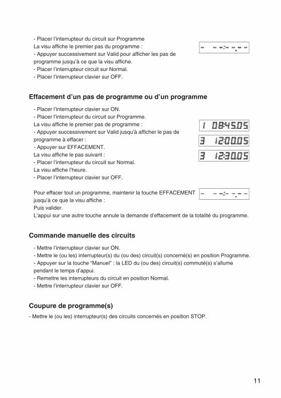
- Placer l’interrupteur du circuit sur ProgrammeLa visu affiche le premier pas du programme :- Appuyer successivement sur Valid pour afficher les pas deprogramme jusqu’à ce que la visu affiche.- Placer l’interrupteur circuit sur Normal.- Placer l’interrupteur clavier sur OFF.
Effacement d’un pas de programme ou d’un programme
- Placer l’interrupteur clavier sur ON.- Placer l’interrupteur du circuit sur Programme.La visu affiche le premier pas de programme :- Appuyer successivement sur Valid jusqu’à afficher le pas deprogramme à effacer :- Appuyer sur EFFACEMENT.La visu affiche le pas suivant :- Placer l’interrupteur du circuit sur Normal.La visu affiche l’heure.- Placer l’interrupteur clavier sur OFF.
Pour effacer tout un programme, maintenir la touche EFFACEMENTjusqu’à ce que la visu affiche :Puis valider.L’appui sur une autre touche annule la demande d’effacement de la totalité du programme.
Commande manuelle des circuits
- Mettre l’interrupteur clavier sur ON.- Mettre le (ou les) interrupteur(s) du (ou des) circuit(s) concerné(s) en position Programme.- Appuyer sur la touche “Manuel” : la LED du (ou des) circuit(s) commuté(s) s’allumependant le temps d’appui.- Remettre les interrupteurs du circuit en position Normal.- Mettre l’interrupteur clavier sur OFF.
Coupure de programme(s)
- Mettre le (ou les) interrupteur(s) des circuits concernés en position STOP.
11
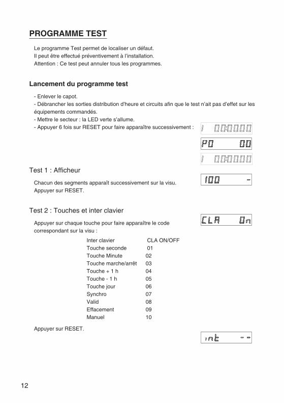
PROGRAMME TEST
Le programme Test permet de localiser un défaut.Il peut être effectué préventivement à l’installation.Attention : Ce test peut annuler tous les programmes.
Lancement du programme test
- Enlever le capot.- Débrancher les sorties distribution d’heure et circuits afin que le test n’ait pas d’effet sur leséquipements commandés.- Mettre le secteur : la LED verte s’allume.- Appuyer 6 fois sur RESET pour faire apparaître successivement :
Test 1 : Afficheur
Chacun des segments apparaît successivement sur la visu.Appuyer sur RESET.
Test 2 : Touches et inter clavier
Appuyer sur chaque touche pour faire apparaître le codecorrespondant sur la visu :
Inter clavier CLA ON/OFFTouche seconde 01Touche Minute 02Touche marche/arrêt 03Touche + 1 h 04Touche - 1 h 05Touche jour 06Synchro 07Valid 08Effacement 09Manuel 10
Appuyer sur RESET.
12
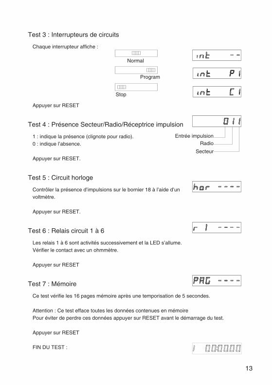
Test 3 : Interrupteurs de circuits
Chaque interrupteur affiche :
Appuyer sur RESET
Test 4 : Présence Secteur/Radio/Réceptrice impulsion
1 : indique la présence (clignote pour radio).0 : indique l’absence.
Appuyer sur RESET.
Test 5 : Circuit horloge
Contrôler la présence d’impulsions sur le bornier 18 à l’aide d’unvoltmètre.
Appuyer sur RESET.
Test 6 : Relais circuit 1 à 6
Les relais 1 à 6 sont activités successivement et la LED s’allume.Vérifier le contact avec un ohmmètre.
Appuyer sur RESET
Test 7 : Mémoire
Ce test vérifie les 16 pages mémoire après une temporisation de 5 secondes.
Attention : Ce test efface toutes les données contenues en mémoirePour éviter de perdre ces données appuyer sur RESET avant le démarrage du test.
Appuyer sur RESET
FIN DU TEST :
13
Entrée impulsionRadio
Secteur
Normal
Program
Stop
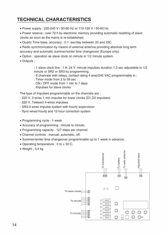
TECHNICAL CHARACTERISTICS
� Power supply : 220-240 V / 50-60 Hz or 110-120 V / 50-60 Hz
� Power reserve : over 72 h by electronic memory providing automatic resetting of slaveclocks as soon as the mains is re-established.
� Quartz Time base, accuracy : 0.1. sec/day between 20 and 25C.
� Radio synchronization by means of external antenna providing absolute long termaccuracy and automatic summer/winter time changeover (Europe only).
� Option : operation as slave clock on minute or 1/2 minute system.
� Outputs :
- 1 slave clock line : 1 A. 24 V. minute impulses duration 1.3 sec adjustable to 1/2minute or SR2 or SR3 by programming.- 6 channels with relays, contact rating 4 amp/240 VAC programmable in :. Timer mode from 2 to 59 sec. ON / OFF mode from 1 min to 7 days. Impulses for slave clocks
The type of impulses programmable on the channels are :- 220 V. 3 wires 1 min impulse for tower clocks (D1,D2 impulses)- 220 V. Telesect 4-wires impulses- SR3-3 wires impulse system with hourly supervision- Sync-wired hourly and 12-hour correction system
� Programming cycle : 1 week
� Accuracy of programming : minute to minute.
� Programming capacity : 127 steps per channel.
� Channel controls : manual, automatic, off.
� Summer/winter time changeover programmable up to 1 week in advance.
� Operating temperature : 0 to + 50 C.
� Weight : 3,4 kg
14
To slave clocks
To circuits
To circuits
To
tran
sfor
mer
To
batte
ry
To
radi
oan
tenn
a
Impu
lses
inpu
t
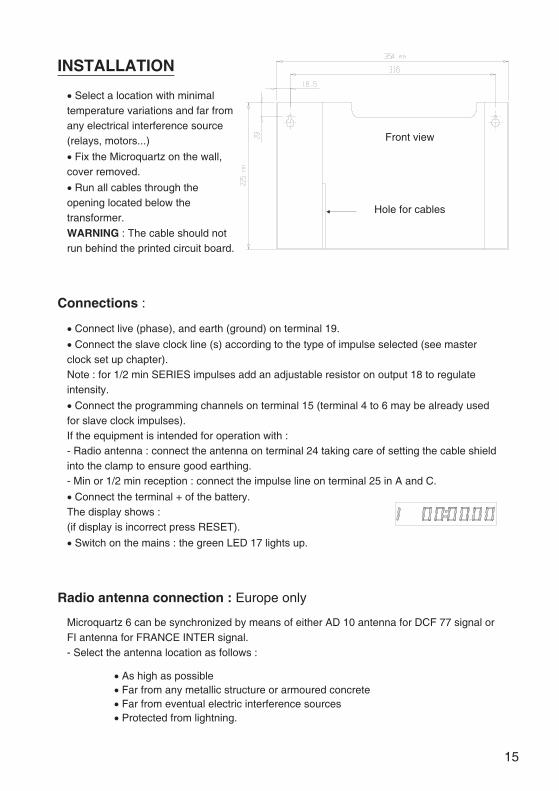
INSTALLATION
� Select a location with minimaltemperature variations and far fromany electrical interference source(relays, motors...)
� Fix the Microquartz on the wall,cover removed.
� Run all cables through theopening located below thetransformer.
WARNING : The cable should notrun behind the printed circuit board.
Connections :
� Connect live (phase), and earth (ground) on terminal 19.
� Connect the slave clock line (s) according to the type of impulse selected (see masterclock set up chapter).Note : for 1/2 min SERIES impulses add an adjustable resistor on output 18 to regulateintensity.
� Connect the programming channels on terminal 15 (terminal 4 to 6 may be already usedfor slave clock impulses).If the equipment is intended for operation with :- Radio antenna : connect the antenna on terminal 24 taking care of setting the cable shieldinto the clamp to ensure good earthing.- Min or 1/2 min reception : connect the impulse line on terminal 25 in A and C.
� Connect the terminal + of the battery.The display shows :(if display is incorrect press RESET).
� Switch on the mains : the green LED 17 lights up.
Radio antenna connection : Europe only
Microquartz 6 can be synchronized by means of either AD 10 antenna for DCF 77 signal orFI antenna for FRANCE INTER signal.- Select the antenna location as follows :
� As high as possible� Far from any metallic structure or armoured concrete� Far from eventual electric interference sources� Protected from lightning.
15
Front view
Hole for cables
- Open the antenna box.- The antenna must be perpendicular to the transmitter direction :ALLOUIS (F) for FI antenna, MAINFLINGEN (Germany) for DCF and cable joint towards theground.- The position is correct if :
� The LED in antenna box and on Microquartz 6 blinks once per second� The sound in the earphone is clear and disappears once per second (AD 10antenna).
- Fix the antenna on its bracket- Close the box taking care of the waterproof joint.Note : The clock synchronizes itself on time after 5 to 15 minutes. However in case ofdifficult environment it may take as much as 24 h to endure synchronization.
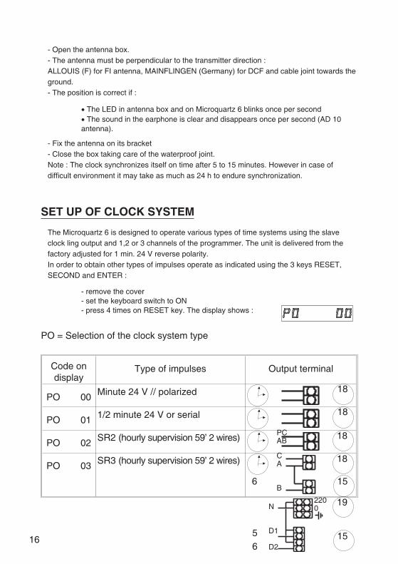
SET UP OF CLOCK SYSTEM
The Microquartz 6 is designed to operate various types of time systems using the slaveclock ling output and 1,2 or 3 channels of the programmer. The unit is delivered from thefactory adjusted for 1 min. 24 V reverse polarity.In order to obtain other types of impulses operate as indicated using the 3 keys RESET,SECOND and ENTER :
- remove the cover- set the keyboard switch to ON- press 4 times on RESET key. The display shows :
PO = Selection of the clock system type
Code ondisplay
Type of impulses Output terminal
PO 00 Minute 24 V // polarized
PO 01 1/2 minute 24 V or serial
PO 02 SR2 (hourly supervision 59’ 2 wires)
PO 03 SR3 (hourly supervision 59’ 2 wires)
16
18
18
18PCAB
CA
B156
18
1556
192200N
D1
D2
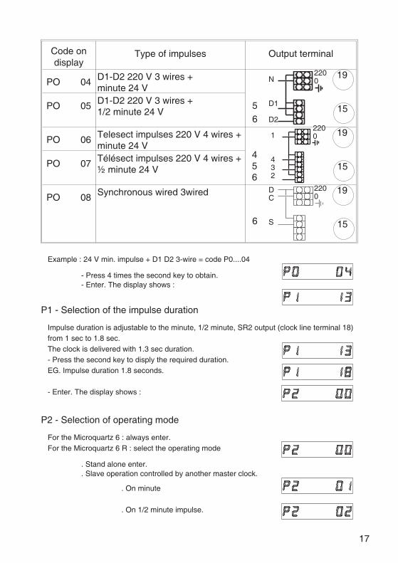
Code ondisplay
Type of impulses Output terminal
PO 04 D1-D2 220 V 3 wires +minute 24 V
PO 05 D1-D2 220 V 3 wires +1/2 minute 24 V
PO 06 Telesect impulses 220 V 4 wires +minute 24 V
PO 07 Télésect impulses 220 V 4 wires +½ minute 24 V
PO 08 Synchronous wired 3wired
Example : 24 V min. impulse + D1 D2 3-wire = code P0....04
- Press 4 times the second key to obtain.- Enter. The display shows :
P1 - Selection of the impulse duration
Impulse duration is adjustable to the minute, 1/2 minute, SR2 output (clock line terminal 18)from 1 sec to 1.8 sec.The clock is delivered with 1.3 sec duration.- Press the second key to disply the required duration.EG. Impulse duration 1.8 seconds.
- Enter. The display shows :
P2 - Selection of operating mode
For the Microquartz 6 : always enter.For the Microquartz 6 R : select the operating mode
. Stand alone enter.
. Slave operation controlled by another master clock.
. On minute
. On 1/2 minute impulse.
17
15456
1922001
432
156
192200
DC
S
1556
192200N
D1
D2
P3 Selection of radio synchro mode (P2-00 must be entered)
P3...00 : official time by DCF 77 or FRANCE INTERP3... 1 : official time by DCF 77 or FRANCE INTER plus 1 hourP3...— : Synchro radio without summer / winter time changeoverP3...-1 : official time by DCF 77 ofr FRANCE INTER less 1 hour- Enter : The display shows the 1st programme step enteredThe programming is completed.
Programme control
- Press successively on ENTER to display the programme steps.
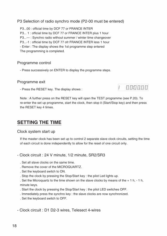
Programme exit
- Press the RESET key. The display shows :
Note : A further press on the RESET key will open the TEST programme (see P.20). Tore-enter the set up programme, start the clock, then stop it (Start/Stop key) and then pressthe RESET key 4 times.
SETTING THE TIME
Clock system start up
If the master clock has been set up to control 2 separate slave clock circuits, setting the timeof each circuit is done independently to allow for the reset of one circuit only.
- Clock circuit : 24 V minute, 1/2 minute, SR2/SR3
. Set all slave clocks on the same time.
. Remove the cover of the MICROQUARTZ.
. Set the keyboard switch to ON.
. Stop the clock by pressing the Stop/Start key : the pilot Led lights up.
. Set the Microquartz to the time shown on the slave clocks by means of the + 1 h, - 1 h,minute keys.. Start the clock by pressing the Stop/Start key : the pilot LED switches OFF.. Immediately press the synchro key : the slave clocks are now synchronized.. Set the keyboard switch to OFF.
- Clock circuit : D1 D2-3 wires, Telesect 4-wires
18
Set the channel 1 switch C6 (13) on programme position then proceed as above.. Replace switch C6 in normal position.
Setting the time of the Microquartz
- Set the keyboard switch to ON.- Stop the clock by pressing the Stop/start key : the red LED lights up.- Set the clock to the exact day and time using the + 1 h, - 1 h, min keys.- On the time signal press the Start/Stop key : the red LED switches OFF, the second startcounting.- Set the keyboard switch to OFF
The slave clocks will synchronize themselves automatically either catching up or in stand-byif they are ahead less than 1 h. catching up cycle is 24 h.
Note : It is possible to check the slave clocks time at any time :- for min 24 V, 1/2 min 24 V and SR2 / SR3 by pressing the enter key,- for D1 D2 and Telesect by setting the channel 6 (13) switch to program and pressing theenter key.
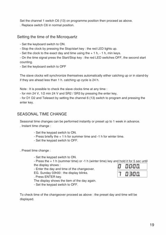
SEASONAL TIME CHANGE
Seasonal time changes can be performed instantly or preset up to 1 week in advance.. Instant time change :
- Set the keypad switch to ON.- Press briefly the + 1 h for summer time and -1 h for winter time.- Set the keypad switch to OFF.
. Preset time change :
- Set the keypad switch to ON.- Press the + 1 h (summer time) or -1 h (winter time) key and hold it for 5 sec untilthe display shows :- Enter the day and time of the changeover.EG. Sunday 03h00 : the display blinks.. Press ENTER key.The display shows the tiem of the day again.- Set the keypad switch to OFF.
To check time of the changeover proceed as above : the preset day and time will bedisplayed.
19
PROGRAMMING OF THE CHANNELS
The 6 channels can be programmed in TIMER MODE (bells) or in ON/OFF mode.
To program a channel :
- Set the corresponding channel switch to Program mode.- Key-in the day, hour, minute, signal duration (or ON/OFF) by means of the day,hour, minute and sec keys.- The display blinks : data are on stand-by.- Enter : the display becomes still (data are recorded).
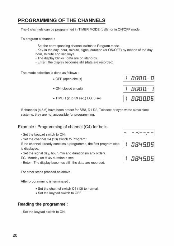
The mode selection is done as follows :
� OFF (open circuit)
� ON (closed circuit)
� TIMER (2 to 59 sec.) EG. 6 sec
If channels (4,5,6) have been preset for SR3, D1 D2, Telesect or sync-wired slave clocksystems, they are not accessible for programming.
Example : Programming of channel (C4) for bells
- Set the keypad switch to ON.- Set the channel C4 (13) switch to Program :If the channel already contains a programme, the first program stepis displayed.- Set the signal day, hour, min and duration (in any order).EG. Monday 08 H 45 duration 5 sec.- Enter : The display becomes still, the data are recorded.
For other steps proceed as above.
After programming is terminated :
� Set the channel switch C4 (13) to normal.� Set the keypad switch to OFF.
Reading the programme :
- Set the keypad switch to ON.
20
- Set the circuit switch to Program.The display shows the 1st programme step.
- Press the ENTER key repeatedly to display the programme untilthe display shows :- Set the circuit switch to Normal.- Set the keypad switch to OFF.
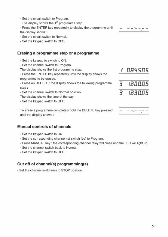
Erasing a programme step or a programme
- Set the keypad to switch to ON.- Set the channel switch to Program.The display shows the 1st programme step.- Press the ENTER key repeatedly until the display shows theprogramme to be erased.- Press on DELETE : the display shows the following programmestep :- Set the channel switch to Normal position.The display shows the time of the day.- Set the keypad switch to OFF.
To erase a programme completely hold the DELETE key presseduntil the display shows :
Manual controls of channels
- Set the keypad switch to ON.- Set the corresponding channel (s) switch (es) to Program.- Press MANUAL key : the corresponding channel relay will close and the LED will light up.- Set the channel switch back to Normal.- Set the keypad switch to OFF.
Cut off of channel(s) programming(s)
- Set the channel switch(es) to STOP position
21
TEST PROGRAMME
This test is designed for trouble shooting.It can be performed when installing.Caution : This test cancels all the programming.
Starting the test programme :
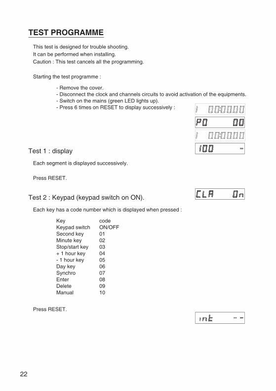
- Remove the cover.- Disconnect the clock and channels circuits to avoid activation of the equipments.- Switch on the mains (green LED lights up).- Press 6 times on RESET to display successively :
Test 1 : display
Each segment is displayed successively.
Press RESET.
Test 2 : Keypad (keypad switch on ON).
Each key has a code number which is displayed when pressed :
Key codeKeypad switch ON/OFFSecond key 01Minute key 02Stop/start key 03+ 1 hour key 04- 1 hour key 05Day key 06Synchro 07Enter 08Delete 09Manual 10
Press RESET.
22
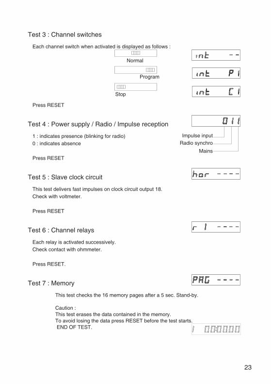
Test 3 : Channel switches
Each channel switch when activated is displayed as follows :
Press RESET
Test 4 : Power supply / Radio / Impulse reception
1 : indicates presence (blinking for radio)0 : indicates absence
Press RESET
Test 5 : Slave clock circuit
This test delivers fast impulses on clock circuit output 18.Check with voltmeter.
Press RESET
Test 6 : Channel relays
Each relay is activated successively.Check contact with ohmmeter.
Press RESET.
Test 7 : Memory
This test checks the 16 memory pages after a 5 sec. Stand-by.
Caution :This test erases the data contained in the memory.To avoid losing the data press RESET before the test starts.END OF TEST.
23
Impulse inputRadio synchro
Mains
Normal
Program
Stop

24