Notice d'utilisation Caméra 3D©ra 3D 6 6. Montage Le chapitre décrit ce qu'il faut connaître...
59
Notice d'utilisation Caméra 3D O3D301 O3D303 O3D311 O3D313 706397 / 06 04 / 2018 FR
Transcript of Notice d'utilisation Caméra 3D©ra 3D 6 6. Montage Le chapitre décrit ce qu'il faut connaître...
Notice d'utilisation Caméra 3D
O3D301 O3D303 O3D311 O3D313
7063
97 /
06
04 /
2018
FR
Caméra 3D
2
Contenu1. Remarques préliminaires. . . . . . . . . . . . . . . . . . . . . . . . . . . . . . . . . . . . . . . . . . . . . . . . . . . . . . . . . . . .4
1.1 Symboles utilisés . . . . . . . . . . . . . . . . . . . . . . . . . . . . . . . . . . . . . . . . . . . . . . . . . . . . . . . . . . . . . .41.2 Avertissements utilisés . . . . . . . . . . . . . . . . . . . . . . . . . . . . . . . . . . . . . . . . . . . . . . . . . . . . . . . . . .4
2. Consignes de sécurité . . . . . . . . . . . . . . . . . . . . . . . . . . . . . . . . . . . . . . . . . . . . . . . . . . . . . . . . . . . . .42.1 Remarques générales . . . . . . . . . . . . . . . . . . . . . . . . . . . . . . . . . . . . . . . . . . . . . . . . . . . . . . . . . .42.2 Cible . . . . . . . . . . . . . . . . . . . . . . . . . . . . . . . . . . . . . . . . . . . . . . . . . . . . . . . . . . . . . . . . . . . . . .42.3 Raccordement électrique . . . . . . . . . . . . . . . . . . . . . . . . . . . . . . . . . . . . . . . . . . . . . . . . . . . . . . . .42.4 Interventions sur l'appareil . . . . . . . . . . . . . . . . . . . . . . . . . . . . . . . . . . . . . . . . . . . . . . . . . . . . . . .4
3. Fonctionnement et caractéristiques. . . . . . . . . . . . . . . . . . . . . . . . . . . . . . . . . . . . . . . . . . . . . . . . . . . .5
4. Fourniture . . . . . . . . . . . . . . . . . . . . . . . . . . . . . . . . . . . . . . . . . . . . . . . . . . . . . . . . . . . . . . . . . . . . . .5
5. Accessoires . . . . . . . . . . . . . . . . . . . . . . . . . . . . . . . . . . . . . . . . . . . . . . . . . . . . . . . . . . . . . . . . . . . . . .5
6. Montage . . . . . . . . . . . . . . . . . . . . . . . . . . . . . . . . . . . . . . . . . . . . . . . . . . . . . . . . . . . . . . . . . . . . . .66.1 Sélectionner le lieu de montage . . . . . . . . . . . . . . . . . . . . . . . . . . . . . . . . . . . . . . . . . . . . . . . . . . .66.2 Préparer l'appareil pour la mise en service. . . . . . . . . . . . . . . . . . . . . . . . . . . . . . . . . . . . . . . . . . .7
6.2.1 Limites d'avertissement typiques pour O3D301 / O3D303. . . . . . . . . . . . . . . . . . . . . . . . . . .76.2.2 Limites d'avertissement typiques pour O3D311 / O3D313 . . . . . . . . . . . . . . . . . . . . . . . . . . .86.2.3 Réduire la température de surface . . . . . . . . . . . . . . . . . . . . . . . . . . . . . . . . . . . . . . . . . . . . .8
6.3 Installer l'appareil . . . . . . . . . . . . . . . . . . . . . . . . . . . . . . . . . . . . . . . . . . . . . . . . . . . . . . . . . . . . . .96.4 Accessoires de montage . . . . . . . . . . . . . . . . . . . . . . . . . . . . . . . . . . . . . . . . . . . . . . . . . . . . . . . .9
7. Raccordement électrique. . . . . . . . . . . . . . . . . . . . . . . . . . . . . . . . . . . . . . . . . . . . . . . . . . . . . . . . . . .107.1 Schéma de branchement . . . . . . . . . . . . . . . . . . . . . . . . . . . . . . . . . . . . . . . . . . . . . . . . . . . . . . .10
7.1.1 Broches 1 / 3 (24 V / GND). . . . . . . . . . . . . . . . . . . . . . . . . . . . . . . . . . . . . . . . . . . . . . . . . . 117.1.2 Broche 2 (entrée trigger). . . . . . . . . . . . . . . . . . . . . . . . . . . . . . . . . . . . . . . . . . . . . . . . . . . . 117.1.3 Bornes 4 / 5 (ready / cascade) . . . . . . . . . . . . . . . . . . . . . . . . . . . . . . . . . . . . . . . . . . . . . . . 11
7.2 Exemples de câblage . . . . . . . . . . . . . . . . . . . . . . . . . . . . . . . . . . . . . . . . . . . . . . . . . . . . . . . . . .127.2.1 Déclencher la capture d'images avec un détecteur de proximité . . . . . . . . . . . . . . . . . . . . .127.2.2 Monter plusieurs appareils l'un à côté de l'autre. . . . . . . . . . . . . . . . . . . . . . . . . . . . . . . . . .13
8. Eléments de visualisation . . . . . . . . . . . . . . . . . . . . . . . . . . . . . . . . . . . . . . . . . . . . . . . . . . . . . . . . . .14
9. Mise en service . . . . . . . . . . . . . . . . . . . . . . . . . . . . . . . . . . . . . . . . . . . . . . . . . . . . . . . . . . . . . . . . . .159.1 Paramétrer l'appareil. . . . . . . . . . . . . . . . . . . . . . . . . . . . . . . . . . . . . . . . . . . . . . . . . . . . . . . . . . .159.2 Détecter un objet . . . . . . . . . . . . . . . . . . . . . . . . . . . . . . . . . . . . . . . . . . . . . . . . . . . . . . . . . . . . .15
10. Maintenance, réparation et élimination . . . . . . . . . . . . . . . . . . . . . . . . . . . . . . . . . . . . . . . . . . . . . . .1610.1 Nettoyage . . . . . . . . . . . . . . . . . . . . . . . . . . . . . . . . . . . . . . . . . . . . . . . . . . . . . . . . . . . . . . . . . .1610.2 Mettre à jour le firmware . . . . . . . . . . . . . . . . . . . . . . . . . . . . . . . . . . . . . . . . . . . . . . . . . . . . . . .1610.3 Remplacer l'appareil . . . . . . . . . . . . . . . . . . . . . . . . . . . . . . . . . . . . . . . . . . . . . . . . . . . . . . . . . .16
11. Homologations/normes . . . . . . . . . . . . . . . . . . . . . . . . . . . . . . . . . . . . . . . . . . . . . . . . . . . . . . . . . . .16
12. Schémas d'encombrement . . . . . . . . . . . . . . . . . . . . . . . . . . . . . . . . . . . . . . . . . . . . . . . . . . . . . . . .1712.1 O3D303 / O3D313 . . . . . . . . . . . . . . . . . . . . . . . . . . . . . . . . . . . . . . . . . . . . . . . . . . . . . . . . . . .1712.2 O3D301 / O3D311 . . . . . . . . . . . . . . . . . . . . . . . . . . . . . . . . . . . . . . . . . . . . . . . . . . . . . . . . . . .17
13. Appendix . . . . . . . . . . . . . . . . . . . . . . . . . . . . . . . . . . . . . . . . . . . . . . . . . . . . . . . . . . . . . . . . . . . . .1813.1 Required Ports . . . . . . . . . . . . . . . . . . . . . . . . . . . . . . . . . . . . . . . . . . . . . . . . . . . . . . . . . . . . . .1813.2 XML-RPC Interface. . . . . . . . . . . . . . . . . . . . . . . . . . . . . . . . . . . . . . . . . . . . . . . . . . . . . . . . . . .18
13.2.1 Sample XML-RPC command . . . . . . . . . . . . . . . . . . . . . . . . . . . . . . . . . . . . . . . . . . . . . . .1813.2.2 XML-RPC Objects . . . . . . . . . . . . . . . . . . . . . . . . . . . . . . . . . . . . . . . . . . . . . . . . . . . . . . .19
13.3 Process Interface . . . . . . . . . . . . . . . . . . . . . . . . . . . . . . . . . . . . . . . . . . . . . . . . . . . . . . . . . . . .2213.3.1 Sending Commands . . . . . . . . . . . . . . . . . . . . . . . . . . . . . . . . . . . . . . . . . . . . . . . . . . . . . .2213.3.2 Receiving Images . . . . . . . . . . . . . . . . . . . . . . . . . . . . . . . . . . . . . . . . . . . . . . . . . . . . . . . .2313.3.3 Image data . . . . . . . . . . . . . . . . . . . . . . . . . . . . . . . . . . . . . . . . . . . . . . . . . . . . . . . . . . . . .2313.3.4 Additional Information for CONFIDENCE_IMAGE . . . . . . . . . . . . . . . . . . . . . . . . . . . . . . .2613.3.5 Configuration of PCIC Output . . . . . . . . . . . . . . . . . . . . . . . . . . . . . . . . . . . . . . . . . . . . . . .27
13.4 Process Interface Command Reference. . . . . . . . . . . . . . . . . . . . . . . . . . . . . . . . . . . . . . . . . . .3213.4.1 t Command (Asynchronous Trigger). . . . . . . . . . . . . . . . . . . . . . . . . . . . . . . . . . . . . . . . . .3213.4.2 T? Command (Synchronous Trigger) . . . . . . . . . . . . . . . . . . . . . . . . . . . . . . . . . . . . . . . . .3213.4.3 I? Command . . . . . . . . . . . . . . . . . . . . . . . . . . . . . . . . . . . . . . . . . . . . . . . . . . . . . . . . . . . .32
3
Caméra 3D
FR
13.4.4 p Command . . . . . . . . . . . . . . . . . . . . . . . . . . . . . . . . . . . . . . . . . . . . . . . . . . . . . . . . . . . .3313.4.5 a Command . . . . . . . . . . . . . . . . . . . . . . . . . . . . . . . . . . . . . . . . . . . . . . . . . . . . . . . . . . . .3413.4.6 A? Command . . . . . . . . . . . . . . . . . . . . . . . . . . . . . . . . . . . . . . . . . . . . . . . . . . . . . . . . . . .3413.4.7 v Command . . . . . . . . . . . . . . . . . . . . . . . . . . . . . . . . . . . . . . . . . . . . . . . . . . . . . . . . . . . .3513.4.8 V? Command . . . . . . . . . . . . . . . . . . . . . . . . . . . . . . . . . . . . . . . . . . . . . . . . . . . . . . . . . . .3513.4.9 c Command . . . . . . . . . . . . . . . . . . . . . . . . . . . . . . . . . . . . . . . . . . . . . . . . . . . . . . . . . . . .3513.4.10 C? Command . . . . . . . . . . . . . . . . . . . . . . . . . . . . . . . . . . . . . . . . . . . . . . . . . . . . . . . . . .3613.4.11 S? Command . . . . . . . . . . . . . . . . . . . . . . . . . . . . . . . . . . . . . . . . . . . . . . . . . . . . . . . . . .3613.4.12 G? Command . . . . . . . . . . . . . . . . . . . . . . . . . . . . . . . . . . . . . . . . . . . . . . . . . . . . . . . . . .3713.4.13 H? Command . . . . . . . . . . . . . . . . . . . . . . . . . . . . . . . . . . . . . . . . . . . . . . . . . . . . . . . . . .3813.4.14 o Command . . . . . . . . . . . . . . . . . . . . . . . . . . . . . . . . . . . . . . . . . . . . . . . . . . . . . . . . . . .3813.4.15 O? Command . . . . . . . . . . . . . . . . . . . . . . . . . . . . . . . . . . . . . . . . . . . . . . . . . . . . . . . . . .3913.4.16 E? Command . . . . . . . . . . . . . . . . . . . . . . . . . . . . . . . . . . . . . . . . . . . . . . . . . . . . . . . . . .39
13.5 Error codes . . . . . . . . . . . . . . . . . . . . . . . . . . . . . . . . . . . . . . . . . . . . . . . . . . . . . . . . . . . . . . . . .4013.6 XML-RPC Command Reference . . . . . . . . . . . . . . . . . . . . . . . . . . . . . . . . . . . . . . . . . . . . . . . .41
13.6.1 Parameter API . . . . . . . . . . . . . . . . . . . . . . . . . . . . . . . . . . . . . . . . . . . . . . . . . . . . . . . . . .4113.6.2 Main Object. . . . . . . . . . . . . . . . . . . . . . . . . . . . . . . . . . . . . . . . . . . . . . . . . . . . . . . . . . . . .4213.6.3 Session Object . . . . . . . . . . . . . . . . . . . . . . . . . . . . . . . . . . . . . . . . . . . . . . . . . . . . . . . . . .4513.6.4 Edit Mode Object . . . . . . . . . . . . . . . . . . . . . . . . . . . . . . . . . . . . . . . . . . . . . . . . . . . . . . . .4713.6.5 Device Config Object . . . . . . . . . . . . . . . . . . . . . . . . . . . . . . . . . . . . . . . . . . . . . . . . . . . . .4813.6.6 Device/Network Config Object . . . . . . . . . . . . . . . . . . . . . . . . . . . . . . . . . . . . . . . . . . . . . .5213.6.7 Application Config Object . . . . . . . . . . . . . . . . . . . . . . . . . . . . . . . . . . . . . . . . . . . . . . . . . .5213.6.8 Application/Imager Config Object . . . . . . . . . . . . . . . . . . . . . . . . . . . . . . . . . . . . . . . . . . . .5413.6.9 Image Settings and Filter Parameters . . . . . . . . . . . . . . . . . . . . . . . . . . . . . . . . . . . . . . . .59
Licences et marques
Microsoft®, Windows®, Windows Vista®, Windows 7®, Windows 8®, Windows 8.1® et Windows 10® sont des marques enregistrées de Microsoft Corporation.
Adobe® et Acrobat® sont des marques enregistrées d'Adobe Systems Inc.
Toutes les marques et raisons sociales utilisées sont soumises au copyright des sociétés respectives.
Cet appareil contient du logiciel Open Source (modifié si nécessaire) qui est sujet à des termes de licence spécifiques.
Remarques concernant le droit d'auteur et les termes de licence sur :
www.ifm.com/int/GNU
Pour du logiciel sujet à la licence publique générale GNU ou la licence publique générale limitée GNU, le texte source peut être demandé contre paiement des frais de copie et d'envoi.

Caméra 3D
4
1. Remarques préliminairesCe document s'adresse à des personnes compétentes. Ce sont des personnes qui sont capables – grâce à leur formation et expérience – d’envisager les risques et d'éviter des dangers potentiels qui pourraient être causés par le fonctionnement ou la maintenance de l'appareil. Le document fournit des informations sur l'utilisation correcte de l'appareil.
Lire ce document avant l'utilisation afin de vous familiariser avec les conditions d'utilisation, l'installation et le fonctionnement. Garder ce document pendant tout le temps d'utilisation de l'appareil.
1.1 Symboles utilisés► Action à faire> Retour d'information, résultat[…] Désignation d'une touche, d'un bouton ou d'un affichage→ Référence croisée
Remarque importante Le non-respect peut aboutir à des dysfonctionnements ou perturbations.Information Remarque supplémentaire
1.2 Avertissements utilisés
ATTENTION Avertissement de dommages matériels.
2. Consignes de sécurité 2.1 Remarques généralesCette notice fait partie de l'appareil. Elle fournit des textes et des figures pour l'utilisation correcte de l'appareil et doit être lue avant installation ou emploi.
Respecter les indications de cette notice. Le non-respect de ces consignes, une utilisation en dehors des conditions définies ci-dessous, une mauvaise installation ou utilisation peuvent avoir des conséquences graves pour la sécurité des personnes et des installations.
2.2 CibleCette notice s'adresse à des personnes considérées comme compétentes selon les directives CEM et basse tension. L'appareil doit être monté, raccordé et mis en service par un électricien habilité.
2.3 Raccordement électriqueMettre l'appareil hors tension en prenant des mesures externes avant toutes manipulations.
Les bornes de raccordement ne doivent être alimentées que par les signaux indiqués dans les données techniques et sur l'étiquette de l'appareil et seuls les accessoires homologués d'ifm doivent être raccordés.
2.4 Interventions sur l'appareilEn cas de mauvais fonctionnement de l'appareil ou en cas de doute prendre contact avec le fabricant. Des interventions sur l'appareil peuvent avoir des conséquences graves pour la sécurité des personnes et des installations. Elles ne sont pas autorisées et aboutissent à une exclusion de responsabilité et de garantie.
5
Caméra 3D
FR
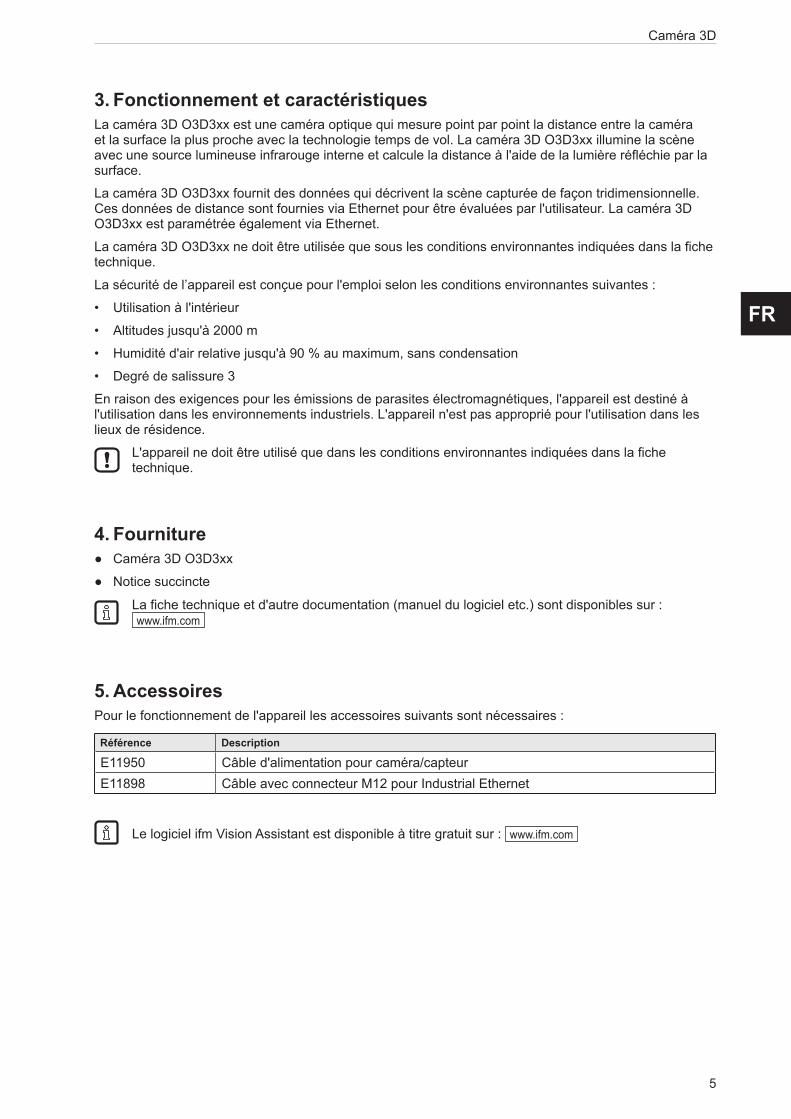
3. Fonctionnement et caractéristiquesLa caméra 3D O3D3xx est une caméra optique qui mesure point par point la distance entre la caméra et la surface la plus proche avec la technologie temps de vol. La caméra 3D O3D3xx illumine la scène avec une source lumineuse infrarouge interne et calcule la distance à l'aide de la lumière réfléchie par la surface.
La caméra 3D O3D3xx fournit des données qui décrivent la scène capturée de façon tridimensionnelle. Ces données de distance sont fournies via Ethernet pour être évaluées par l'utilisateur. La caméra 3D O3D3xx est paramétrée également via Ethernet.
La caméra 3D O3D3xx ne doit être utilisée que sous les conditions environnantes indiquées dans la fiche technique.
La sécurité de l’appareil est conçue pour l'emploi selon les conditions environnantes suivantes :
• Utilisation à l'intérieur
• Altitudes jusqu'à 2000 m
• Humidité d'air relative jusqu'à 90 % au maximum, sans condensation
• Degré de salissure 3
En raison des exigences pour les émissions de parasites électromagnétiques, l'appareil est destiné à l'utilisation dans les environnements industriels. L'appareil n'est pas approprié pour l'utilisation dans les lieux de résidence.
L'appareil ne doit être utilisé que dans les conditions environnantes indiquées dans la fiche technique.
4. Fourniture ● Caméra 3D O3D3xx
● Notice succincte
La fiche technique et d'autre documentation (manuel du logiciel etc.) sont disponibles sur : www.ifm.com
5. AccessoiresPour le fonctionnement de l'appareil les accessoires suivants sont nécessaires :
Référence Description
E11950 Câble d'alimentation pour caméra/capteurE11898 Câble avec connecteur M12 pour Industrial Ethernet
Le logiciel ifm Vision Assistant est disponible à titre gratuit sur : www.ifm.com

Caméra 3D
6
6. MontageLe chapitre décrit ce qu'il faut connaître avant le montage et comment l'appareil doit être installé.
②
①
③
④
⑤
① Appareil
② Angle d'ouverture
③ Objet
④ Champ de vue
⑤ Distance entre l'appareil et l'objet
6.1 Sélectionner le lieu de montageObserver les instructions suivantes pour la sélection du lieu de montage :
► L'objet ③ doit se trouver intégralement dans le champ de vue ④.
> La taille du champ de vue dépend de la version de l'appareil et est indiquée dans la fiche technique. La taille du champ de vue dépend aussi de la distance entre l'appareil et l'objet ⑤ : Le champ de vue devient plus grand lorsque l’on augmente la distance.
► Prendre en considération les tolérances pour le positionnement de l'objet.
► Pour définir la distance entre l'appareil et l'objet ⑤, prendre en considération l'étendue de mesure de l'appareil.
> L'étendue de mesure est indiquée dans la fiche technique de l'appareil.
► Choisir une distance entre l'appareil et l'objet ⑤ aussi petite que possible.
> Avec une distance minimale, l'objet est détecté avec la résolution maximale.
► Eviter une forte lumière ambiante et les rayons solaires sur le lieu de montage.
> Un niveau de lumière ambiante (ayant un spectre solaire) au-dessus de 8 klx cause des erreurs de mesure. En effet, uniquement la lumière infrarouge entre 800 et 900 nm est perturbante.
► Eviter les zones à forts encrassements comme lieu de montage.
> Dans des zones à forts encrassements, l'objectif est souillé malgré une orientation vers le bas ①.
► Eviter des vitres transparentes entre l'appareil ① et l'objet ③.
> Les vitres transparentes réfléchissent une partie de la lumière, même si un plateau de verre très propre est utilisé.
Si les instructions ne sont pas respectées, des erreurs de mesure sont possibles.

7
Caméra 3D
FR
6.2 Préparer l'appareil pour la mise en serviceLa température de surface de l'appareil dépend du mode de fonctionnement, de la sélection des paramètres et de la connexion thermique de l'appareil avec le support de montage.
S'assurer que l'appareil satisfait aux exigences suivantes :
La température de surface, pour les surfaces facilement accessibles, peut être au maximum supérieure de 25 °C à la température ambiante (selon CEI 61010-2-201).
Les diagrammes suivants montrent les limites d'avertissement typiques auxquelles l'installateur peut se reporter.
Les diagrammes sont valables pour les modes d’exposition suivants:
● un temps d'exposition
● deux temps d'exposition
● trois temps d'exposition
Avec deux ou trois temps d'exposition, les limites d'avertissement typiques doivent être déterminées en faisant la somme des temps d'exposition. Les temps d'exposition sont indiqués dans le logiciel ifm Vision Assistant.
Respecter une des indications suivantes si les limites d'avertissement sont dépassées :
► Réduire la température de surface (→ 6.2.3).
► Monter une protection contre le contact sans diminuer la convection (circulation d’air).
> La température de surface ne doit pas être augmentée une fois cette protection contre le contact installée.
Le paramètre "Distance maximale de visibilité" est réglé dans le logiciel ifm Vision Assistant. Les limites d'avertissement sont indiquées dans les diagrammes comme des lignes pointillées et continues.
Si l'appareil se trouve dans une des zones pointillées, la température de surface doit être réduite (→ 6.2.3). Si la limite d'avertissement est dépassée malgré un montage évacuant la chaleur, une protection contre le contact peut être montée en plus.
Si les limites d'avertissement typiques ne sont pas atteintes en cas de montage normal, aucune mesure n'est nécessaire.
6.2.1 Limites d'avertissement typiques pour O3D301 / O3D303
0
5
10
15
0 2 4 6 8 10
x
y
20
25
Paramètre "Distance maximale de visibilité"
Montage sur des pièces métalliques conduisant la chaleur
avec conducteur thermique (→ 6.2.3)
Limite d'avertissement Paramètre
< 5 m
< 30 m
> 30 m
Montage normal
Limite d'avertissement Paramètre
< 5 m
< 30 m
> 30 m
x = temps d'exposition [ms] y = taux d’images [fps]

Caméra 3D
8
6.2.2 Limites d'avertissement typiques pour O3D311 / O3D313
0
5
10
15
0 2 4 6 8 10
x
y
20
25
Paramètre "Distance maximale de visibilité"
Montage sur des pièces métalliques conduisant la chaleur
avec conducteur thermique (→ 6.2.3)
Limite d'avertissement Paramètre
< 5 m
< 30 m
> 30 m
Montage normal
Limite d'avertissement Paramètre
< 5 m
< 30 m
> 30 m
x = temps d'exposition [ms] y = taux d’images [fps]
6.2.3 Réduire la température de surfaceLa température de surface peut être réduite par les mesures suivantes :
► Fixer l'appareil sur des pièces métalliques conduisant la chaleur.
> La fixation de l'appareil sur une grande surface métallique augmente l'évacuation de la chaleur (par ex. aluminium).
► Utiliser un conducteur thermique en cas de montage sur des pièces métalliques.
> L'effet conducteur de chaleur est augmenté par le conducteur thermique. Le conducteur thermique est disponible comme accessoire (→ 6.4).
► Réduire toute entrave dans l'environnement de l'appareil et la densité d'objets.
> Toute entrave dans l'environnement de l'appareil et une densité d'appareils augmentée peuvent avoir des effets négatifs sur la convection (mouvement de l'air).
► Monter un ou deux dissipateurs thermiques sur l'appareil.
> Les dissipateurs thermiques augmentent la surface de l'appareil ce qui réduit la température de surface. Les dissipateurs thermiques sont disponibles comme accessoires (→ 6.4).
► Réduire le temps d'exposition, le taux d’images ou la distance maximale visible.
> Le mode de fonctionnement utilisé et les paramètres peuvent augmenter la température de surface.
9
Caméra 3D
FR
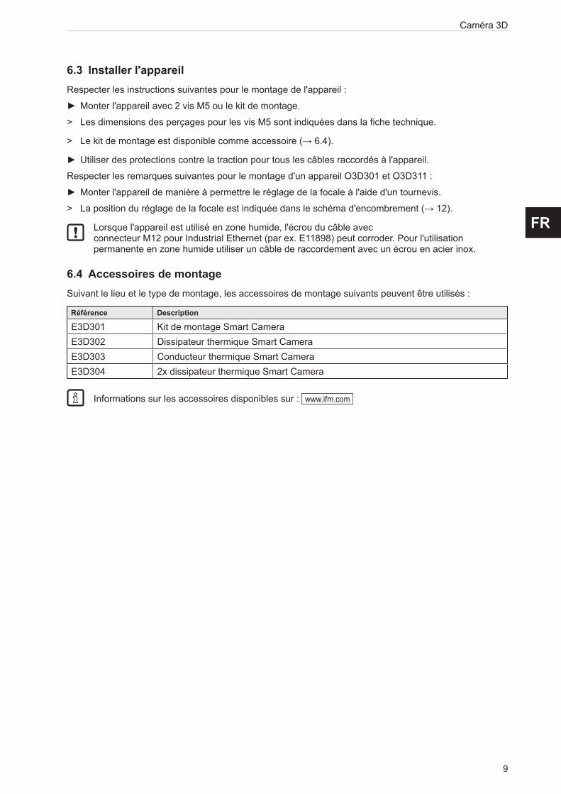
6.3 Installer l'appareilRespecter les instructions suivantes pour le montage de l'appareil :
► Monter l'appareil avec 2 vis M5 ou le kit de montage.
> Les dimensions des perçages pour les vis M5 sont indiquées dans la fiche technique.
> Le kit de montage est disponible comme accessoire (→ 6.4).
► Utiliser des protections contre la traction pour tous les câbles raccordés à l'appareil.
Respecter les remarques suivantes pour le montage d'un appareil O3D301 et O3D311 :
► Monter l'appareil de manière à permettre le réglage de la focale à l'aide d'un tournevis.
> La position du réglage de la focale est indiquée dans le schéma d'encombrement (→ 12).
Lorsque l'appareil est utilisé en zone humide, l'écrou du câble avec connecteur M12 pour Industrial Ethernet (par ex. E11898) peut corroder. Pour l'utilisation permanente en zone humide utiliser un câble de raccordement avec un écrou en acier inox.
6.4 Accessoires de montageSuivant le lieu et le type de montage, les accessoires de montage suivants peuvent être utilisés :
Référence Description
E3D301 Kit de montage Smart CameraE3D302 Dissipateur thermique Smart CameraE3D303 Conducteur thermique Smart CameraE3D304 2x dissipateur thermique Smart Camera
Informations sur les accessoires disponibles sur : www.ifm.com

Caméra 3D
10
7. Raccordement électriqueRespecter les remarques suivantes avant l'installation électrique.
ATTENTION L'appareil doit être raccordé par un électricien qualifié. Respecter les données électriques de la fiche technique.
Appareil de la classe de protection III (CP III).
L'alimentation électrique ne doit s'effectuer que via des circuits TBTP.
L'alimentation électrique doit être conforme à UL 61010-1, chap. 9.4 - Limited Energy :
Le dispositif de limitation des surtensions doit désactiver un courant de 6,6 A en 120 s. Pour le dimensionnement du dispositif de limitation des surtensions, respecter les données techniques de l'appareil et du câblage.
L'isolation des circuits externes doit être conforme à UL61010-2-201, fig. 102.
Pour des longueurs de câble > 30 m, utiliser une protection supplémentaire contre des tenues au choc selon CEI 6100-4-5.
Avant le raccordement électrique mettre l'installation hors tension.
Dans le champ d'application cULus: Plage de température haute minimum du câble qui doit être raccordé au capteur : 70 °C.
7.1 Schéma de branchement
① EthernetConnecteur femelle M12, codage D, 4 pôles
����������������
�
� �
��
��� ��
��������
�
� �
�
�
1 TD + 2 RD + 3 TD - 4 RD - S Shield (blindage)
② Alimentation en courantConnecteur mâle M12, codage A, 5 pôles
4
2 1
35
1 U+ 2 entrée trigger 3 GND 4 sortie de commutation 1 - ready 5 sortie de commutation 2 - cascade
Protéger la prise de connexion Ethernet non utilisée avec un bouchon (E73004). Couple de serrage 0,6...0,8 Nm.
Le comportement des entrées et sorties de commutation peut être réglé par le logiciel ifm Vision Assistant. Le réglage commutation PNP ou NPN est toujours valable pour toutes les entrées et sorties.
S'assurer du réglage correct pour l'installation des actionneurs et capteurs (par ex. barrages optoélectroniques pour le déclenchement).
Les sorties de commutation peuvent aussi être utilisées comme sorties impulsionnelles qui remettent leur signal de commutation à 0 après un temps réglable.
11
Caméra 3D
FR
7.1.1 Broches 1 / 3 (24 V / GND)La plage de tension admissible est indiquée dans la fiche technique de l'appareil.
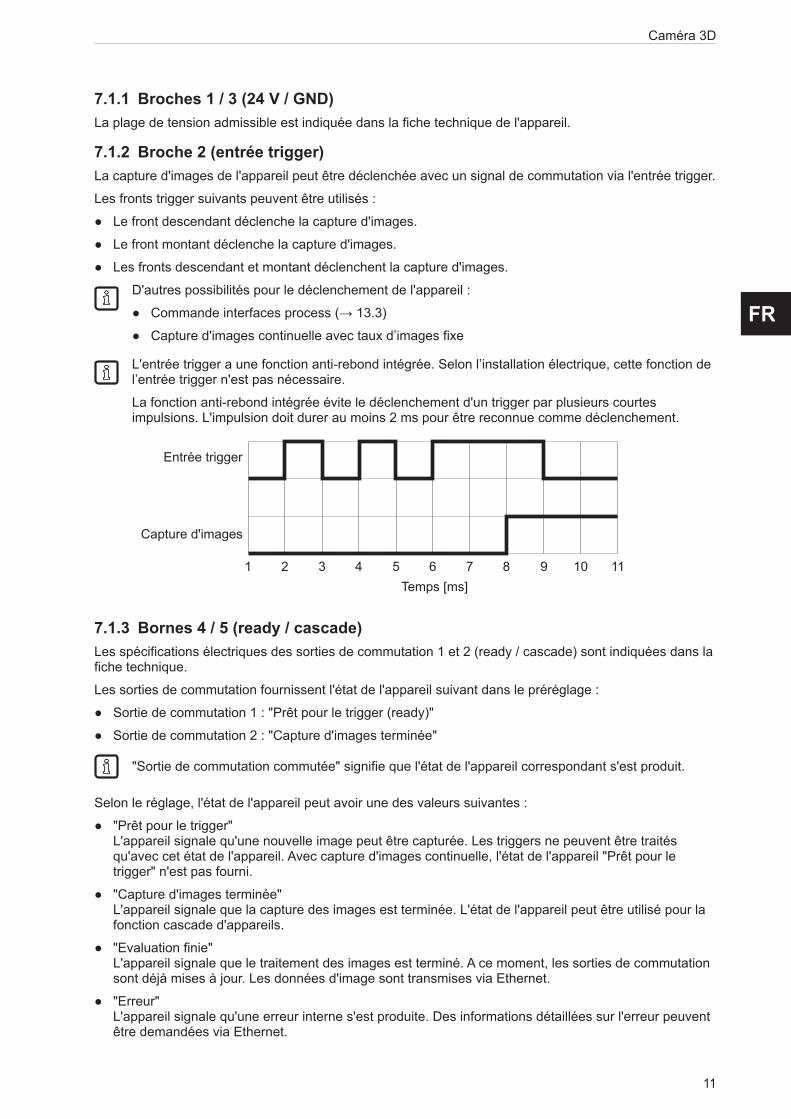
7.1.2 Broche 2 (entrée trigger)La capture d'images de l'appareil peut être déclenchée avec un signal de commutation via l'entrée trigger.
Les fronts trigger suivants peuvent être utilisés :
● Le front descendant déclenche la capture d'images.
● Le front montant déclenche la capture d'images.
● Les fronts descendant et montant déclenchent la capture d'images.
D'autres possibilités pour le déclenchement de l'appareil :
● Commande interfaces process (→ 13.3)
● Capture d'images continuelle avec taux d’images fixe
L'entrée trigger a une fonction anti-rebond intégrée. Selon l’installation électrique, cette fonction de l’entrée trigger n'est pas nécessaire.
La fonction anti-rebond intégrée évite le déclenchement d'un trigger par plusieurs courtes impulsions. L'impulsion doit durer au moins 2 ms pour être reconnue comme déclenchement.
7.1.3 Bornes 4 / 5 (ready / cascade)Les spécifications électriques des sorties de commutation 1 et 2 (ready / cascade) sont indiquées dans la fiche technique.
Les sorties de commutation fournissent l'état de l'appareil suivant dans le préréglage :
● Sortie de commutation 1 : "Prêt pour le trigger (ready)"
● Sortie de commutation 2 : "Capture d'images terminée"
"Sortie de commutation commutée" signifie que l'état de l'appareil correspondant s'est produit.
Selon le réglage, l'état de l'appareil peut avoir une des valeurs suivantes :
● "Prêt pour le trigger" L'appareil signale qu'une nouvelle image peut être capturée. Les triggers ne peuvent être traités qu'avec cet état de l'appareil. Avec capture d'images continuelle, l'état de l'appareil "Prêt pour le trigger" n'est pas fourni.
● "Capture d'images terminée" L'appareil signale que la capture des images est terminée. L'état de l'appareil peut être utilisé pour la fonction cascade d'appareils.
● "Evaluation finie" L'appareil signale que le traitement des images est terminé. A ce moment, les sorties de commutation sont déjà mises à jour. Les données d'image sont transmises via Ethernet.
● "Erreur" L'appareil signale qu'une erreur interne s'est produite. Des informations détaillées sur l'erreur peuvent être demandées via Ethernet.
Capture d'images
Entrée trigger
Temps [ms]1 2 3 4 5 6 7 8 9 10 11

Caméra 3D
12
7.2 Exemples de câblageCi-dessous, des exemples de câblage de l'appareil sont montrés.
7.2.1 Déclencher la capture d'images avec un détecteur de proximitéL'appareil peut être déclenché de manière externe :
● via Ethernet
● via un détecteur de proximité, raccordé à l'entrée trigger
La figure suivante montre le câblage de l'appareil à un détecteur de proximité.
3 1 2 4 5
1 2
34
4
2 1
35
DC 24 V+ -
IN IN
①
② ③
①: PC portable (paramétrage)
②: Détecteur de proximité
③: PC industriel (évaluation / déclenchement)

13
Caméra 3D
FR
7.2.2 Monter plusieurs appareils l'un à côté de l'autreDes appareils montés l'un à côté de l'autre peuvent causer des erreurs de mesure en cas d’exposition simultanée.
① ②
③
① Appareil
② Appareil
③ Objet
Il y a deux manières d'éviter les erreurs de mesure :
● Cascader les appareils via trigger matériel Lors de cette fonction cascade, un système de commande déclenche la capture du 1er appareil. Après la fin de la capture des images, le 1er appareil déclenche automatiquement le 2e appareil. Le 2e appareil signale la fin de la séquence au système de commande.
3 1 2 4 5
4
2 1
35
DC 24 V+ -
IN IN
3 1 2 4 5
①
①: PC industriel (évaluation / déclenchement)
● Utiliser des canaux de fréquences différents. Avec le logiciel ifm Vision Assistant un canal de fréquences individuel peut être affecté à chaque appareil. Les différents canaux de fréquences réduisent la présence d'erreurs de mesure.
Le logiciel ifm Vision Assistant est disponible à titre gratuit sur : www.ifm.com
Caméra 3D
14
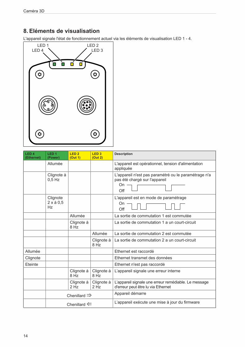
8. Eléments de visualisation L'appareil signale l'état de fonctionnement actuel via les éléments de visualisation LED 1 - 4.
LED 4 LED 3LED 1 LED 2
LED 4 (Ethernet)
LED 1 (Power)
LED 2 (Out 1)
LED 3 (Out 2)
Description
Allumée L'appareil est opérationnel, tension d'alimentation appliquée
Clignote à 0,5 Hz
L'appareil n'est pas paramétré ou le paramétrage n'a pas été chargé sur l'appareil
On
On
Off
Off
Clignote 2 x à 0,5 Hz
L'appareil est en mode de paramétrage
On
On
Off
OffAllumée La sortie de commutation 1 est commutéeClignote à 8 Hz
La sortie de commutation 1 a un court-circuit
Allumée La sortie de commutation 2 est commutéeClignote à 8 Hz
La sortie de commutation 2 a un court-circuit
Allumée Ethernet est raccordéClignote Ethernet transmet des donnéesEteinte Ethernet n'est pas raccordé
Clignote à 8 Hz
Clignote à 8 Hz
L’appareil signale une erreur interne
Clignote à 2 Hz
Clignote à 2 Hz
L’appareil signale une erreur remédiable. Le message d'erreur peut être lu via Ethernet
Chenillard ⇒ Appareil démarre
Chenillard ⇐ L’appareil exécute une mise à jour du firmware

15
Caméra 3D
FR
9. Mise en serviceA la mise sous tension l'appareil est mis en service. Après 15 secondes, l'appareil se trouve en mode d’évaluation dans lequel les applications sauvegardées sont exécutées. Les éléments de visualisation signalent l'état de fonctionnement actuel (→ 8).
Jusqu'à 32 applications peuvent être sauvegardées sur l'appareil. Une application inclut typiquement les paramètres suivants :
● Capture d'images : par ex. déclenchement de la capture d'images, temps d'exposition, filtre de traitement d'images
● Interface : Ethernet, sorties de commutation
L'application correspondante peut être activée avec le logiciel ifm Vision Assistant ou via des commandes d'interface process.
9.1 Paramétrer l'appareilIl y a deux manières de paramétrer l'appareil :
● Logiciel ifm Vision Assistant (→ voir Manuel du logiciel)
● Commandes XML-RPC (→ 13.6)
L'utilisation du logiciel ifm Vision Assistant et des informations détaillées sur le principe de mesure de l'appareil sont décrits dans le manuel de programmation.
Le manuel du logiciel est disponible sur : www.ifm.com
9.2 Détecter un objetCi-dessous, les conditions qui mènent à un haut taux de détection d'objets sont décrites.
③
②
④
②
①① Appareil
② Zone d'influence
③ Champ de vue
④ Objet
Un objet ④ est détecté de façon optimale, si les conditions suivantes sont satisfaites :
● L'objet est positionné dans le champ de vue ③.
● L'objet à détecter est l'objet le plus proche visible par l'appareil①.
● La zone d'influence ② est libre d'objets (entrave etc.).
● La vitre avant de l'appareil est libre de salissures.
Si ces conditions ne sont pas satisfaites, des erreurs de mesure sont possibles.

Caméra 3D
16
10. Maintenance, réparation et éliminationRespecter les instructions suivantes :
► Ne pas ouvrir l'appareil. A l'intérieur de l'appareil il n'y a pas de composants réparables par l'utilisateur. L'appareil ne doit être réparé que par le fabricant.
► Respecter la réglementation du pays en vigueur pour la destruction écologique de l'appareil.
10.1 NettoyageObserver les instructions suivantes avant le nettoyage de l'appareil :
► Utiliser un chiffon propre et sans peluches.
► Comme produit lessiviel, utiliser un nettoyant à vitres.
Si ces instructions ne sont pas respectées, des erreurs de mesure sur la vitre avant, causées par des rayures, sont possibles.
10.2 Mettre à jour le firmwareLe firmware de l'appareil peut être mis à jour avec le logiciel ifm Vision Assistant.
Les paramètres sauvegardés dans l'appareil sont perdus par la mise à jour du firmware. Avant la mise à jour du firmware, faire une copie de sauvegarde des paramètres.
► Avant la mise à jour du firmware, exporter les paramètres.
► Après la mise à jour du firmware, importer les paramètres.
Les mises à jour du firmware sont disponibles sur : www.ifm.com
10.3 Remplacer l'appareilLors du remplacement d'un appareil les paramètres sont perdus. Avant le remplacement de l'appareil, faire une copie de sauvegarde des paramètres.
► Avant le remplacement, exporter les paramètres de l'appareil à remplacer.
► Après le remplacement, importer les paramètres dans le nouvel appareil.
Avec l'exportation et l'importation des paramètres il est possible d'équiper plusieurs appareils rapidement avec les mêmes paramètres.
11. Homologations/normesLa déclaration de conformité UE est disponible sur : www.ifm.com

17
Caméra 3D
FR
12. Schémas d'encombrement12.1 O3D303 / O3D313
Original Scale Drawing (MTD)
EPS SourceProduct Scale DrawingFrame Size: 80 mm x 45 mm
P_MZ_200_0359
O3D302O3D303O3D312O3D313
33
3
5,7M
12x1
4014
9582,6
73,3
71,6
72
6532,5
21
332
M12x133
3
5,7
M12
x140
14
9582,6
73,3
71,6
72
6532,5
21
33
2
M12x1
①: Objectif
②: Unité d'éclairage
③: LED 2 couleurs (jaune/verte)
12.2 O3D301 / O3D311
Original Scale Drawing (MTD)
EPS SourceProduct Scale DrawingFrame Size: 80 mm x 45 mm
P_MZ_200_0362
O3D300O3D301O3D310O3D311
33
3
5,7
M12
x140
14
9582,6
73,3
71,6
49
17,1
28,7
4
M12x1
72
6532,5
2
21
33
67,1
33
3
5,7
M12
x140
14
9582,6
73,3
71,6
49
17,1
28,7
4
M12x1
72
6532,5
2
21
33
67,1
①: Objectif
②: Unité d'éclairage
③: LED 2 couleurs (jaune/verte)
④: Réglage de la focale
Caméra 3D
18
13. Appendix13.1 Required PortsThe following ports are required for the camera configuration using XML-RPC and for receiving data on the process interface. They must not be blocked by a firewall or router.
● TCP/HTTP: 80
● TCP: 50010
If the ifm Vision Assistant is used, the following additional ports must also be available:
● UDP: 3321
● TCP/HTTP: 8080
It is possible to configure another port than 50010 for the process interface. If a different port is used, it must not be blocked either.
13.2 XML-RPC InterfaceIn case the O3D3xx camera should not be configured by the “ifmVisionAssistant”, the XML-RPC interface can be used instead.
General information about XML-RPC is found on the website http://xmlrpc.scripting.com/spec
To send a command via the XML-RPC interface the command is in a special layout. In this command, linefeeds and carriage returns are essential.
Every command which is sent via the XML-RPC interface must end with carriage return <CR> and linefeed <LF>.
Several commands will use different URLs in the XML-RPC header.
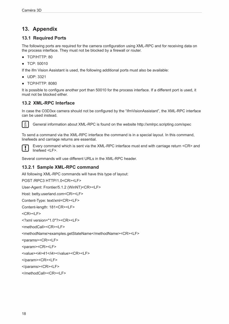
13.2.1 Sample XML-RPC commandAll following XML-RPC commands will have this type of layout:
POST /RPC3 HTTP/1.0<CR><LF>
User-Agent: Frontier/5.1.2 (WinNT)<CR><LF>
Host: betty.userland.com<CR><LF>
Content-Type: text/xml<CR><LF>
Content-length: 181<CR><LF>
<CR><LF>
<?xml version="1.0"?><CR><LF>
<methodCall><CR><LF>
<methodName>examples.getStateName</methodName><CR><LF>
<params><CR><LF>
<param><CR><LF>
<value><i4>41</i4></value><CR><LF>
</param><CR><LF>
</params><CR><LF>
</methodCall><CR><LF>

19
Caméra 3D
FR
The following example contains one O3D3xx command:
POST /api/rpc/v1/com.ifm.efector/ HTTP/1.1 <CR><LF>
User-Agent: Frontier/5.1.2 (WinNT)<CR><LF>
Host: 192.168.0.69<CR><LF>
Content-Type: text/xml<CR><LF>
Content-length: 94<CR><LF>
<CR><LF>
<?xml version="1.0"?><CR><LF>
<methodCall><CR><LF>
<methodName>getParameter</methodName><CR><LF>
</methodCall><CR><LF>
13.2.2 XML-RPC ObjectsTo communicate and to configure the device via XML-RPC the XML-RPC commands have to use different XML-RPC objects. Different commands need different XML-RPC objects (see XML-RPC command references).
The interface of O3D3xx is structured in an object-oriented way. Some of the objects are available all the time, others are only available after bringing the device into a special mode by calling a method on an already available object. This mechanism is used to create system requirements (e.g. password protection).
It could be necessary to send heartbeats so that there will be no session timeout.
The following diagram should give an overview how objects are related to each other and which methods must be called to make others available:
Main API
Session
EditMode
ApplicationConfig
requestSession(...)
setOperatingMode(1)
editApplication(1) DeviceConfig
NetworkConfig
ImagerConfig
Caméra 3D
20
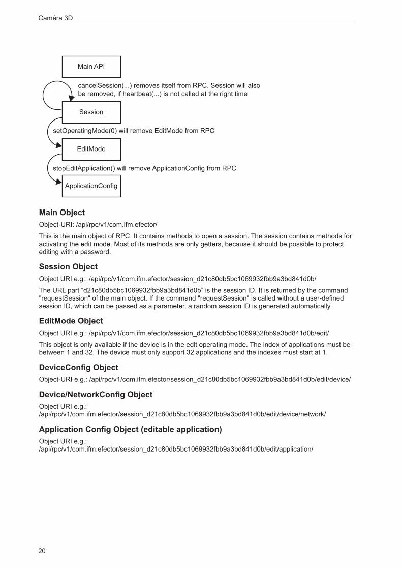
Main ObjectObject-URI: /api/rpc/v1/com.ifm.efector/
This is the main object of RPC. It contains methods to open a session. The session contains methods for activating the edit mode. Most of its methods are only getters, because it should be possible to protect editing with a password.
Session ObjectObject URI e.g.: /api/rpc/v1/com.ifm.efector/session_d21c80db5bc1069932fbb9a3bd841d0b/
The URL part “d21c80db5bc1069932fbb9a3bd841d0b” is the session ID. It is returned by the command "requestSession" of the main object. If the command "requestSession" is called without a user-defined session ID, which can be passed as a parameter, a random session ID is generated automatically.
EditMode ObjectObject URI e.g.: /api/rpc/v1/com.ifm.efector/session_d21c80db5bc1069932fbb9a3bd841d0b/edit/
This object is only available if the device is in the edit operating mode. The index of applications must be between 1 and 32. The device must only support 32 applications and the indexes must start at 1.
DeviceConfig ObjectObject-URI e.g.: /api/rpc/v1/com.ifm.efector/session_d21c80db5bc1069932fbb9a3bd841d0b/edit/device/
Device/NetworkConfig ObjectObject URI e.g.: /api/rpc/v1/com.ifm.efector/session_d21c80db5bc1069932fbb9a3bd841d0b/edit/device/network/
Application Config Object (editable application)Object URI e.g.: /api/rpc/v1/com.ifm.efector/session_d21c80db5bc1069932fbb9a3bd841d0b/edit/application/
Main API
Session
EditMode
ApplicationConfig
cancelSession(...) removes itself from RPC. Session will also be removed, if heartbeat(...) is not called at the right time
setOperatingMode(0) will remove EditMode from RPC
stopEditApplication() will remove ApplicationConfig from RPC

21
Caméra 3D
FR
Application/Imager Config Object (O3D3xx)Object URI e.g.: /api/rpc/v1/com.ifm.efector/session_d21c80db5bc1069932fbb9a3bd841d0b/edit/application/imager_001/
As there is only one imager config on O3D3xx, the ID must be fixed to "001". Data of this object is persistently saved when calling "save" on the application config object. The imager config RPC object has multiple sub-types. Only parameters relevant for a specific type are available while it is active. They are based on frequency (extending the distance) and integration intervals (extending the measurement details).
Type names, based on GUI draft (under 5 metres -> single frequency, up to 30 metres -> double frequency, more than 30 metres -> triple frequency.):
under5m_low
under5m_moderate
under5m_high
upto30m_low
upto30m_moderate
upto30m_high
morethan30m_low
morethan30m_moderate
Image Settings and Filter ParametersThere is an RPC object for spatial filter parameters in each imager configuration.
Object URI e.g.: /api/rpc/v1/com.ifm.efector/session_d21c80db5bc1069932fbb9a3bd841d0b/edit/application/imager_001/spatialfilter
There is an RPC object for temporal filter parameters in each imager configuration.
Object URI e.g.: /api/rpc/v1/com.ifm.efector/session_d21c80db5bc1069932fbb9a3bd841d0b/edit/application/imager_001/temporalfilter
Data of these objects is persistently saved when calling "save" on application config object.
Caméra 3D
22
13.3 Process InterfaceThe process interface is used during the normal operation mode to get operational data (e.g. 3D images, process values) from the O3D3xx.
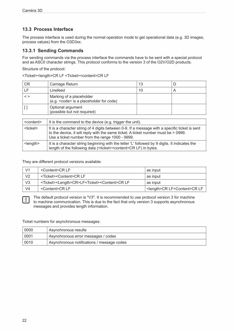
13.3.1 Sending CommandsFor sending commands via the process interface the commands have to be sent with a special protocol and as ASCII character strings. This protocol conforms to the version 3 of the O2V/O2D products.
Structure of the protocol:
<Ticket><length>CR LF <Ticket><content>CR LF
CR Carriage Return 13 DLF Linefeed 10 A< > Marking of a placeholder
(e.g. <code> is a placeholder for code)[ ] Optional argument
(possible but not required)
<content> It is the command to the device (e.g. trigger the unit).<ticket> It is a character string of 4 digits between 0-9. If a message with a specific ticket is sent
to the device, it will reply with the same ticket. A ticket number must be > 0999. Use a ticket number from the range 1000 - 9999.
<length> It is a character string beginning with the letter 'L' followed by 9 digits. It indicates the length of the following data (<ticket><content>CR LF) in bytes.
They are different protocol versions available:
V1 <Content>CR LF as input V2 <Ticket><Content>CR LF as input V3 <Ticket><Length>CR+LF<Ticket><Content>CR LF as input V4 <Content>CR LF <length>CR LF<Content>CR LF
The default protocol version is "V3". It is recommended to use protocol version 3 for machine to machine communication. This is due to the fact that only version 3 supports asynchronous messages and provides length information.
Ticket numbers for asynchronous messages:
0000 Asynchronous results0001 Asynchronous error messages / codes0010 Asynchronous notifications / message codes

23
Caméra 3D
FR
13.3.2 Receiving ImagesFor receiving the image data a TCP/IP socket communication is established. The default port number is 50010. The port number may differ based on the configuration. After opening the socket communication, the O3D3XX device will automatically (if the device is in free run mode) send the data through this socket to the TCP/IP client (PC).
PCIC output per frame. The following data is submitted in this sequence:
Component Content
Ticket and length information (→ 13.4.2)Ticket „0000“Start sequence String "star" (4 bytes)Normalised amplitude image
Output format: 16-bit unsigned integer
1 image
Distance image
Output format: 16-bit integer. Unit: mm.
1 image
X image
Output format: 16-bit signed integer. Unit: mm.
1 image
Y image
Output format: 16-bit signed integer. Unit: mm.
1 image
Z image
Output format: 16-bit signed integer. Unit: mm.
1 image
Confidence image
Output format: 8-bit unsigned integer
1 image
Diagnostic dataStop sequence String "stop" (4 bytes)Ticket signature <CR><LF>
13.3.3 Image dataFor every image there will be a separate chunk. The chunk is part of the response frame data of the process interface.
The header of each chunk contains different kinds of information. This information is separated into bytes. The information contains e.g. the kind of image which will be in the “PIXEL_DATA” and the size of the chunk.
Chunk type:
Offset Name Description Size [byte]
0x0000 CHUNK_TYPE Defines the type of the chunk. For each distinct chunk an own type is defined.
4
0x0004 CHUNK_SIZE Size of the whole image chunk in bytes. After this count of bytes the next chunk starts.
4
0x0008 HEADER_SIZE Number of bytes starting from 0x0000 until PIXEL_DATA.
4
0x000C HEADER_VERSION Version number of the header 40x0010 IMAGE_WIDTH Image width in pixel 40x0014 IMAGE_HEIGTH Image height in pixel 4
Caméra 3D
24
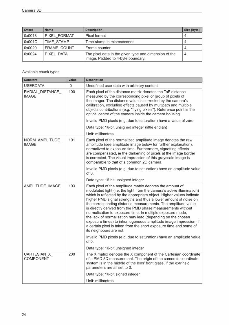
Offset Name Description Size [byte]
0x0018 PIXEL_FORMAT Pixel format 40x001C TIME_STAMP Time stamp in microseconds 40x0020 FRAME_COUNT Frame counter 40x0024 PIXEL_DATA The pixel data in the given type and dimension of the
image. Padded to 4-byte boundary.4
Available chunk types:
Constant Value Description
USERDATA 0 Undefined user data with arbitrary contentRADIAL_DISTANCE_IMAGE
100 Each pixel of the distance matrix denotes the ToF distance measured by the corresponding pixel or group of pixels of the imager. The distance value is corrected by the camera's calibration, excluding effects caused by multipath and multiple objects contributions (e.g. "flying pixels"). Reference point is the optical centre of the camera inside the camera housing.
Invalid PMD pixels (e.g. due to saturation) have a value of zero.
Data type: 16-bit unsigned integer (little endian)
Unit: millimetresNORM_AMPLITUDE_IMAGE
101 Each pixel of the normalized amplitude image denotes the raw amplitude (see amplitude image below for further explanation), normalized to exposure time. Furthermore, vignetting effects are compensated, ie the darkening of pixels at the image border is corrected. The visual impression of this grayscale image is comparable to that of a common 2D camera.
Invalid PMD pixels (e.g. due to saturation) have an amplitude value of 0.
Data type: 16-bit unsigned integerAMPLITUDE_IMAGE 103 Each pixel of the amplitude matrix denotes the amount of
modulated light (i.e. the light from the camera's active illumination) which is reflected by the appropriate object. Higher values indicate higher PMD signal strengths and thus a lower amount of noise on the corresponding distance measurements. The amplitude value is directly derived from the PMD phase measurements without normalisation to exposure time. In multiple exposure mode, the lack of normalisation may lead (depending on the chosen exposure times) to inhomogeneous amplitude image impression, if a certain pixel is taken from the short exposure time and some of its neighbours are not.
Invalid PMD pixels (e.g. due to saturation) have an amplitude value of 0.
Data type: 16-bit unsigned integerCARTESIAN_X_COMPONENT
200 The X matrix denotes the X component of the Cartesian coordinate of a PMD 3D measurement. The origin of the camera's coordinate system is in the middle of the lens' front glass, if the extrinsic parameters are all set to 0.
Data type: 16-bit signed integer
Unit: millimetres

25
Caméra 3D
FR
Constant Value Description
CARTESIAN_Y_COMPONENT
201 The Y matrix denotes the Y component of the Cartesian coordinate of a PMD 3D measurement. The origin of the camera's coordinate system is in the middle of the lens' front glass, if the extrinsic parameters are all set to 0.
Data type: 16-bit signed integer
Unit: millimetresCARTESIAN_Z_COMPONENT
202 The Z matrix denotes the Z component of the Cartesian coordinate of a PMD 3D measurement. The origin of the camera's coordinate system is in the middle of the lens' front glass, if the extrinsic parameters are all set to 0.
Data type: 16-bit signed integer
Unit: millimetresCARTESIAN_ALL 203 CARTESIAN_X_COMPONENT,
CARTESIAN_Y_COMPONENT, CARTESIAN_Z_COMPONENT
UNIT_VECTOR_ALL 223 The unit vector matrix contains 3 values [ex, ey, ez] for each PMD pixel, i.e. the data layout is [ex_1,ey_1,ez_1, ... ex_N, ey_N, ez_N], where N is the number of PMD pixels.
Data type: 32-bit floating point number (3x per pixel)CONFIDENCE_IMAGE 300 See Additional Information for Image Data (→ 13.3.4)DIAGNOSTIC 302 See Receiving Images (→ 13.3.2)
Pixel format:
Constant Value Description
FORMAT_8U 0 8-bit unsigned integerFORMAT_8S 1 8-bit signed integerFORMAT_16U 2 16-bit unsigned integerFORMAT_16S 3 16-bit signed integerFORMAT_32U 4 32-bit unsigned integerFORMAT_32S 5 32-bit signed integerFORMAT_32F 6 32-bit floating point numberFORMAT_64U 7 64-bit unsigned integerFORMAT_64F 8 64-bit floating point numberReserved 9 N/AFORMAT_32F_3 10 Vector with 3x32-bit floating point number

Caméra 3D
26
13.3.4 Additional Information for CONFIDENCE_IMAGEFurther information for the confidence image:
0 1 = pixel invalid Pixel invalid
The pixel is invalid. To determine whether a pixel is valid or not only this bit needs to be checked. The reason why the bit is invalid is recorded in the other confidence bits.
1 1 = pixel saturated Pixel is saturated
Contributes to pixel validity: yes2 1 = bad A-B symmetry A-B pixel symmetry
The A-B symmetry value of the four phase measurements is above threshold.
Remark: This symmetry value is used to detect motion artefacts. Noise (e.g. due to strong ambient light or very short integration times) or PMD interference may also contribute.
Contributes to pixel validity: yes3 1 = amplitude below
minimum amplitude threshold
Amplitude limits
The amplitude value is below minimum amplitude threshold.
Contributes to pixel validity: yes4+5 Bit 5, bit 4
0 0 = unused
0 1 = shortest exposure time (only used in 3 exposure mode)
1 0 = middle exposure time in 3 exposure mode, short exposure in double exposure mode
1 1 = longest exposure time (always 1 in single exposure mode)
Exposure time indicator
The two bits indicate which exposure time was used in a multiple exposure measurement.
Contributes to pixel validity: no
6 1 = pixel is clipped Clipping box on 3D data
If clipping is active this bit indicates that the pixel coordinates are outside the defined volume.
Contributes to pixel validity: yes7 1 = suspect/defective pixel Suspect pixel
This pixel has been marked as "suspect" or "defective" and values have been replaced by interpolated values from the surroundings.
Contributes to pixel validity: no

27
Caméra 3D
FR
13.3.5 Configuration of PCIC OutputThe user has the possibility to define his own PCIC output. This configuration is only valid for the current PCIC connection. It does not affect any other connection and will get lost after disconnecting.
For configuring the PCIC output a “flexible” layouter concept is used, represented by a JSON string. The format of the default configuration is as follows:
{
"layouter": "flexible",
"format": { "dataencoding": "ascii" },
"elements": [
{ "type": "string", "value": "star", "id": "start_string" },
{ "type": "blob", "id": "normalized_amplitude_image" },
{ "type": "blob", "id": "x_image" },
{ "type": "blob", "id": "y_image" },
{ "type": "blob", "id": "z_image" },
{ "type": "blob", "id": "confidence_image" },
{ "type": "blob", "id": "diagnostic_data" },
{ "type": "string", "value": "stop", "id": "end_string" }
]
}
This string can be retrieved by the C? command, altered and sent back using the c command.
The layout software has the following main object properties:
layouter Defines the basic data output format.
So far only “flexible” is supported
Type: string
format Defines format details, the definitions in the main object are the defaults for any of the following data elements (e.g. if it says dataencoding=binary, all data elements should be binary encoded instead of ASCII).
Type: object
elements List of data elements which must be written. Type: array of objects
The actual data is defined within the “elements” properties and may consist of these settings:
type Defines the type of data which must be written.
The data might be stored in a different type (e.g. stored as integer but should be output as Float32)
The type "records" will need some special handling.
Type: string
id Defines an identifier for this data element.
If there is no fixed value (property "value"), the data should be retrieved via id.
Type: string
value Optional property for defining a fixed output value. Type: any JSON valueformat Type-depending option for fine-tuning the output format.
E.g. cut an integer to less than 4 bytes.
Type: object

Caméra 3D
28
Available values for the type property:
records Defines that this element represents a list of records.
If type is set to "records", there must be an "elements" property.
The "elements" property defines which data should be written per record.string Data is written as string.
Most of the time this will be used with "value" property to write fixed start, end or delimiter text.
Text encoding should be UTF8 if there is nothing else specified in format properties.float32 Data is written as floating point number.
This has a lot of formatting options (at least with "flexible" layout software)
See following section about format properties.uint32 Data is written as integer.
This has a lot of formatting options (at least with "flexible" layout software)
See following section about format properties.int32 Data is written as integer.
This has a lot of formatting options (at least with "flexible" layout software)
See following section about format properties.uint16 Limits the output to two bytes in binary encoding, besides the binary limitation it acts like
uint32.int16 Limits the output to two bytes in binary encoding, besides the binary limitation it acts like
int32.uint8 Limits the output to one byte in binary encoding, besides the binary limitation it acts like
uint32.int8 Limits the output to one byte in binary encoding, besides the binary limitation it acts like
int32.blob Data is written as a BLOB (byte by byte as if it came from the data provider).
(Binary Large Object)
Depending on the desired data format the user may tune his output data with further “format” properties.
Common format properties:
dataencoding "ascii" or "binary" can be defined in top-level-object and overwritten by element objects.
"ascii"
scale "float value with decimal separator" to scale the results for output byte width
1.0
offset "float value with decimal separator" 0.0
Binary format properties:
order Little, big and network Little

29
Caméra 3D
FR
ASCII format properties:
width Output width. If the resulting value exceeds the width field the result will not be truncated.
0
fill Fill character " "precision Precision is the number of digits behind the decimalseparator. 6 displayformat Fixed, scientific Fixedalignment Left, right Rightdecimalseparator 7-bit characters for e.g. "." "."base Defines if the output should be:
● binary (2)
● octal (8)
● decimal (10)
● hexadecimal (16)
10
Example of a format configuration of the temperature (id: temp_illu) element.
1. Illumination temperature like this "33,5___":
c000000226{ "layouter": "flexible", "format": { "dataencoding": "ascii" }, "elements": [ { "type": "float32", "id": "temp_illu", "format": { "width": 7, "precision": 1, "fill": "_", "alignment": "left", "decimalseparator": "," } } ] }
2. Illumination temperature as binary (16-bit integer, 1/10 °C):
c000000194{ "layouter": "flexible", "format": { "dataencoding": "ascii" }, "elements": [ { "type": "int16", "id": "temp_illu", "format": { "dataencoding": "binary", "order": "network", "scale": 10 } } ] }
3. Illumination temperature in °F (e.g. "92.3 Fahrenheit" ):
c000000227{ "layouter": "flexible", "format": { "dataencoding": "ascii" }, "elements": [ { "type": "float32", "id": "temp_illu", "format": { "precision": 1, "scale": 1.8, "offset": 32 } }, { "type": "string", "value": " Fahrenheit" } ] }
Caméra 3D
30
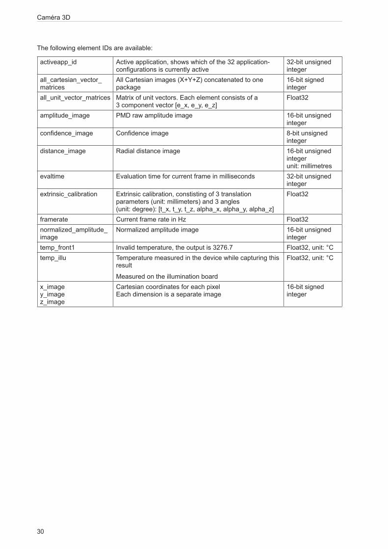
The following element IDs are available:
activeapp_id Active application, shows which of the 32 application-configurations is currently active
32-bit unsigned integer
all_cartesian_vector_matrices
All Cartesian images (X+Y+Z) concatenated to one package
16-bit signed integer
all_unit_vector_matrices Matrix of unit vectors. Each element consists of a 3 component vector [e_x, e_y, e_z]
Float32
amplitude_image PMD raw amplitude image 16-bit unsigned integer
confidence_image Confidence image 8-bit unsigned integer
distance_image Radial distance image 16-bit unsigned integer unit: millimetres
evaltime Evaluation time for current frame in milliseconds 32-bit unsigned integer
extrinsic_calibration Extrinsic calibration, constisting of 3 translation parameters (unit: millimeters) and 3 angles (unit: degree): [t_x, t_y, t_z, alpha_x, alpha_y, alpha_z]
Float32
framerate Current frame rate in Hz Float32normalized_amplitude_image
Normalized amplitude image 16-bit unsigned integer
temp_front1 Invalid temperature, the output is 3276.7 Float32, unit: °Ctemp_illu Temperature measured in the device while capturing this
result
Measured on the illumination board
Float32, unit: °C
x_image y_image z_image
Cartesian coordinates for each pixel Each dimension is a separate image
16-bit signed integer

31
Caméra 3D
FR
For the main object on devices with statistics feature the following IDs are available:
statistics_overall_count Allows the user to output the statistics value with the result of the frame, maps to ModelResults:
adv_statistics.number_of_frames
uint32
statistics_passed_count Allows the user to output the statistics value with the result of the frame, maps to ModelResults:
adv_statistics.number_of_passed_frames
uint32
statistics_failed_count Allows the user to output the statistics value with the result of the frame, maps to ModelResults:
adv_statistics.number_of_failed_frames
uint32
statistics_aborted_count Allows the user to output the statistics value with the result of the frame, maps to ModelResults:
adv_statistics.number_of_aborted_frames
uint32
statistics_acquisition_time_min Allows the user to output the statistics value with the result of the frame,maps to ModelResults:
adv_statistics.frame_acquisition.min
float32
statistics_acquisition_time_mean Allows the user to output the statistics value with the result of the frame,maps to ModelResults:
adv_statistics.frame_acquisition.mean
float32
statistics_acquisition_time_max Allows the user to output the statistics value with the result of the frame,maps to ModelResults:
adv_statistics.frame_acquisition.max
float32
statistics_evaluation_time_min Allows the user to output the statistics value with the result of the frame,maps to ModelResults:
adv_statistics.frame_evaluation.min
float32
statistics_evaluation_time_mean Allows the user to output the statistics value with the result of the frame,maps to ModelResults:
adv_statistics.frame_evaluation.mean
float32
statistics_evaluation_time_max Allows the user to output the statistics value with the result of the frame,maps to ModelResults:
adv_statistics.frame_evaluation.max
float32
statistics_frame_duration_min Allows the user to output the statistics value with the result of the frame,maps to ModelResults:
adv_statistics.frame_duration.min
float32
statistics_frame_duration_mean Allows the user to output the statistics value with the result of the frame,maps to ModelResults:
adv_statistics.frame_duration.mean
float32
statistics_frame_duration_max Allows the user to output the statistics value with the result of the frame,maps to ModelResults:
adv_statistics.frame_duration.max
float32

Caméra 3D
32
13.4 Process Interface Command ReferenceAll received messages which are sent because of the following commands will be sent without “start”/”stop” at the beginning or ending of the string.
13.4.1 t Command (Asynchronous Trigger)Command t
Description Executes trigger. The result data is send asynchronously
Type ActionReply * Trigger was executed, the device
captures an image and evaluates the result.
! ● Device is busy with an evaluation
● Device is in an invalid state for this command, e.g. configuration mode
● Device is set to a different trigger source
● No active application
13.4.2 T? Command (Synchronous Trigger)
Command T?
Description Executes trigger. The result data is send synchronously
Type RequestReply Process data within the
configured layoutTrigger was executed, the device captures an image, evaluates the result and sends the process data.
! ● Device is busy with an evaluation
● Device is in an invalid state for this command, e.g. configuration mode
● Device is set to a different trigger source
● No active application
13.4.3 I? CommandCommand I<image-ID>?
Description Request last image takenType RequestReply <length><image data>
! ● No image available
● Wrong ID? ● Invalid command length

33
Caméra 3D
FR
Note <image-ID>
2 digits for the image type
<length>
char string with exactly 9 digits as decimal number for the image data size in bytes
<image data>
image data
Valid image ID:
01 - amplitude image
02 - normalised amplitude image
03 - distance image
04 - X image (distance information)
05 - Y image (distance information)
06 - Z image (distance information)
07 - confidence image (status information)
08 - extrinsic calibration
09 - unit_vector_matrix_ex, ey,ez
10 - last result output as formatted for this connection
11 - all distance images: X, Y, and Z
13.4.4 p CommandCommand p<state>
Description Turns the PCIC output on or offType ActionReply *
! <state> contains wrong value? Invalid command length
Note <state> 1 digit
0: deactivates all asynchronous output
1: activates asynchronous result output
2: activates asynchronous error output
3: activates asynchronous error and data output
4: activates asynchronous notifications
5: activates asynchronous notifications and asynchronous result
6: activates asynchronous notifications and asynchronous error output
7: activates all outputs
On device restart the value configured within the application is essential for the output of data.
This command can be executed in any device state.
By default the error codes will not be provided by the device.
Caméra 3D
34
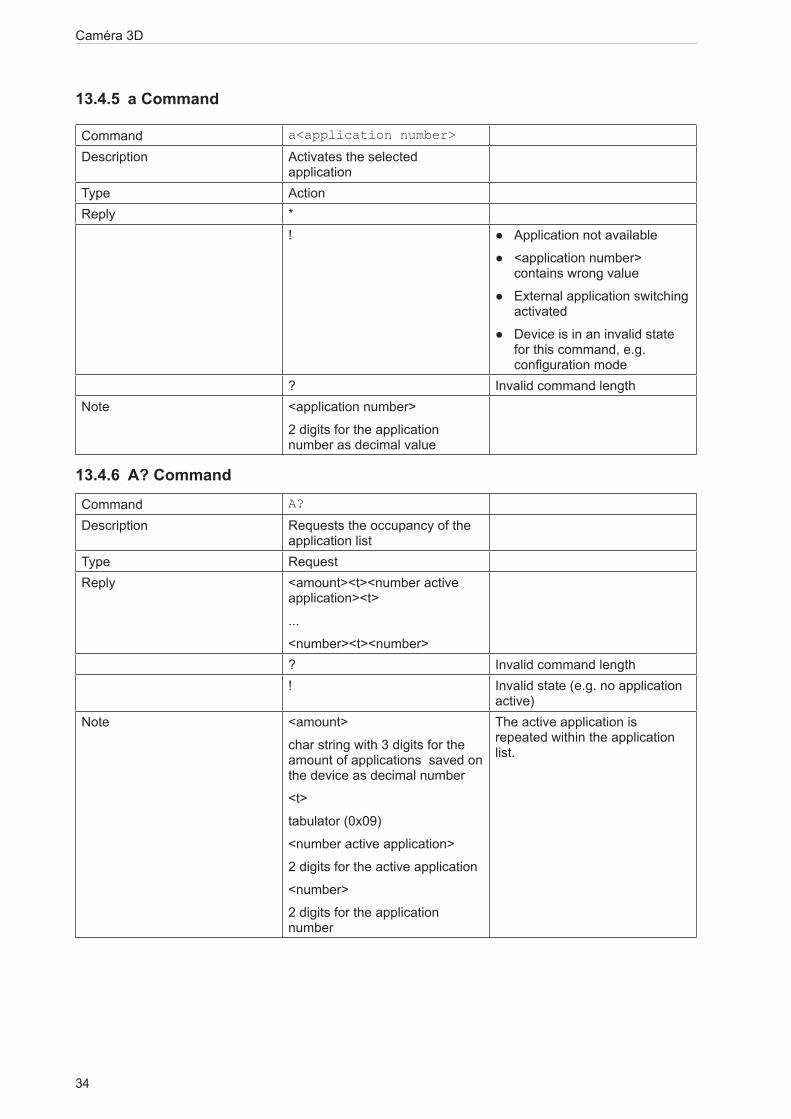
13.4.5 a Command
Command a<application number>
Description Activates the selected application
Type ActionReply *
! ● Application not available
● <application number> contains wrong value
● External application switching activated
● Device is in an invalid state for this command, e.g. configuration mode
? Invalid command lengthNote <application number>
2 digits for the application number as decimal value
13.4.6 A? CommandCommand A?
Description Requests the occupancy of the application list
Type RequestReply <amount><t><number active
application><t>
...
<number><t><number>? Invalid command length! Invalid state (e.g. no application
active)Note <amount>
char string with 3 digits for the amount of applications saved on the device as decimal number
<t>
tabulator (0x09)
<number active application>
2 digits for the active application
<number>
2 digits for the application number
The active application is repeated within the application list.

35
Caméra 3D
FR
13.4.7 v Command
Command v<version>
Description Sets the current protocol version. The device configuration is not affected
Type ActionReply *
! Invalid version? Invalid command length
Note <version>
2 digits for the protocol version
(→ 13.3.1)
The default protocol version is „V3“.
13.4.8 V? CommandCommand V?
Description Requests current protocol version
Type RequestReply <current version><empty><min
version><empty><max version>Note <current version>
2 digits for the currently set version
<empty>
space sign: 0x20
<min/max version>
2 digits for the available min and max version that can be set
13.4.9 c Command
Command c<length><configuration>
Description Uploads a PCIC output configuration lasting this session
Type ActionReply *
! ● Error in configuration
● Wrong data length? Invalid command length
Note <length>
9 digits as decimal value for the data length
<configuration>
configuration data
Caméra 3D
36
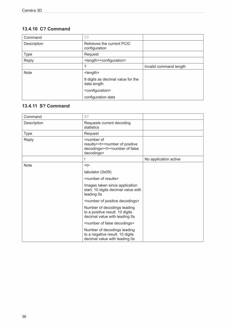
13.4.10 C? CommandCommand C?
Description Retrieves the current PCIC configuration
Type RequestReply <length><configuration>
? Invalid command lengthNote <length>
9 digits as decimal value for the data length
<configuration>
configuration data
13.4.11 S? Command
Command S?
Description Requests current decoding statistics
Type RequestReply <number of
results><t><number of positive decodings><t><number of false decodings>! No application active
Note <t>
tabulator (0x09)
<number of results>
Images taken since application start. 10 digits decimal value with leading 0s
<number of positive decodings>
Number of decodings leading to a positive result. 10 digits decimal value with leading 0s
<number of false decodings>
Number of decodings leading to a negative result. 10 digits decimal value with leading 0s
37
Caméra 3D
FR
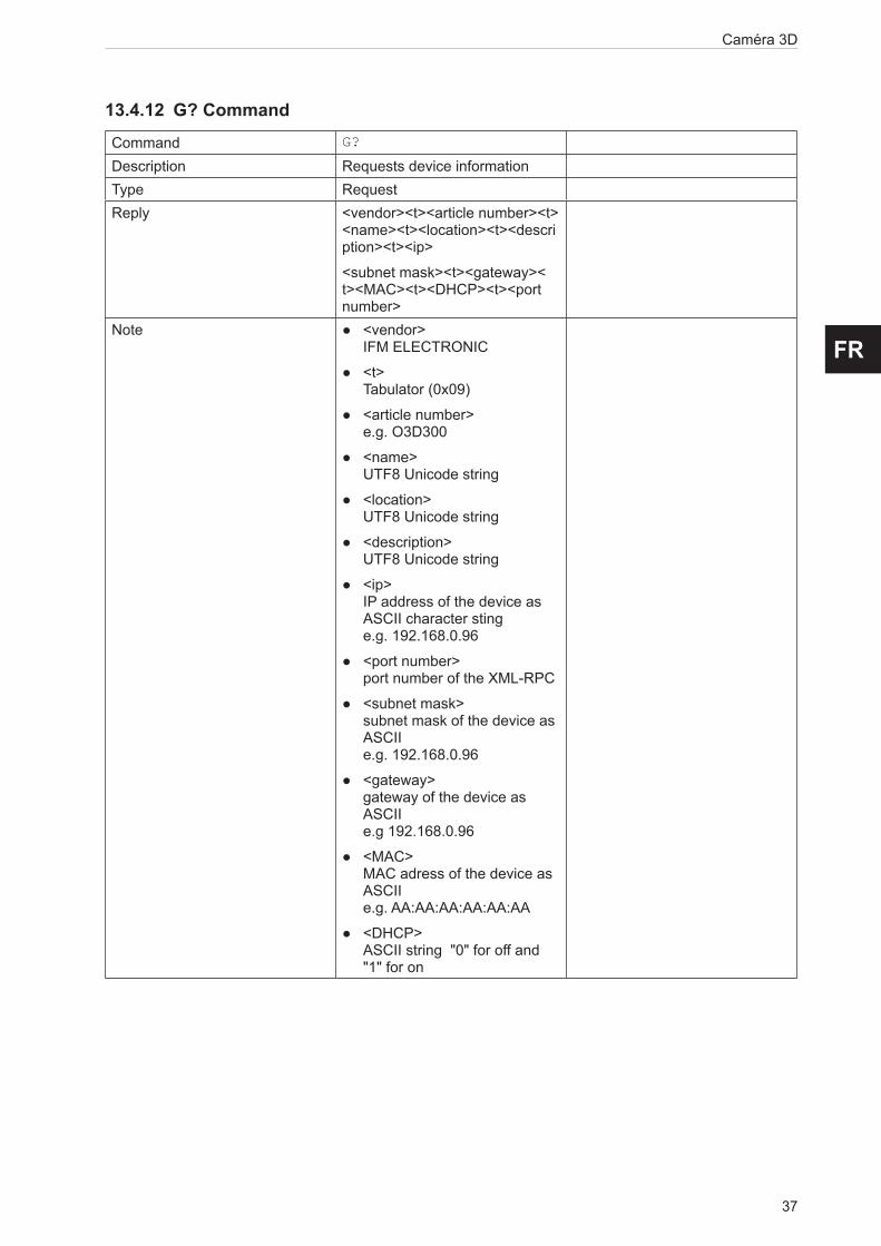
13.4.12 G? CommandCommand G?
Description Requests device informationType RequestReply <vendor><t><article number><t>
<name><t><location><t><description><t><ip>
<subnet mask><t><gateway><t><MAC><t><DHCP><t><port number>
Note ● <vendor> IFM ELECTRONIC
● <t> Tabulator (0x09)
● <article number> e.g. O3D300
● <name> UTF8 Unicode string
● <location> UTF8 Unicode string
● <description> UTF8 Unicode string
● <ip> IP address of the device as ASCII character sting e.g. 192.168.0.96
● <port number> port number of the XML-RPC
● <subnet mask> subnet mask of the device as ASCII e.g. 192.168.0.96
● <gateway> gateway of the device as ASCII e.g 192.168.0.96
● <MAC> MAC adress of the device as ASCII e.g. AA:AA:AA:AA:AA:AA
● <DHCP> ASCII string "0" for off and "1" for on
Caméra 3D
38
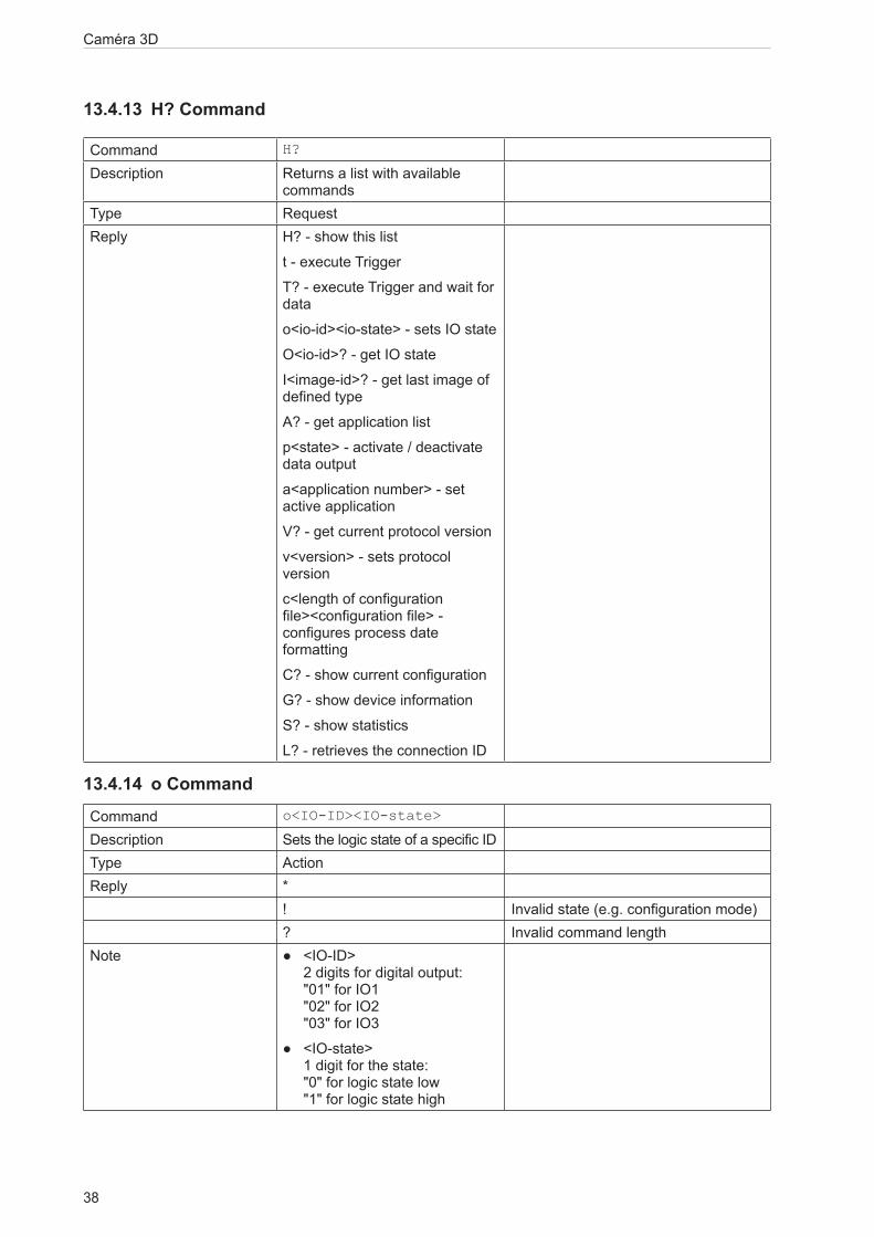
13.4.13 H? Command
Command H?
Description Returns a list with available commands
Type RequestReply H? - show this list
t - execute Trigger
T? - execute Trigger and wait for data
o<io-id><io-state> - sets IO state
O<io-id>? - get IO state
I<image-id>? - get last image of defined type
A? - get application list
p<state> - activate / deactivate data output
a<application number> - set active application
V? - get current protocol version
v<version> - sets protocol version
c<length of configuration file><configuration file> - configures process date formatting
C? - show current configuration
G? - show device information
S? - show statistics
L? - retrieves the connection ID
13.4.14 o CommandCommand o<IO-ID><IO-state>
Description Sets the logic state of a specific IDType ActionReply *
! Invalid state (e.g. configuration mode)? Invalid command length
Note ● <IO-ID> 2 digits for digital output: "01" for IO1 "02" for IO2 "03" for IO3
● <IO-state> 1 digit for the state: "0" for logic state low "1" for logic state high

39
Caméra 3D
FR
13.4.15 O? CommandCommand O<IO-ID>?
Description Requests the state of a specific IDType RequestReply <IO-ID><IO-state>
! ● Invalid state (e.g. configuration mode)
● Wrong ID? Invalid command length
Note ● <IO-ID> 2 digits for digital output: "01" for IO1 "02" for IO2 "03" for IO3
● <IO-state> 1 digit for the state: "0" for logic state low "1" for logic state high
The camera supports ID 1 and ID 2.
The sensor supports ID 1, ID 2 and ID 3.
13.4.16 E? CommandCommand E?
Description Requests the current error stateType RequestReply <code>
! Invalid state (e.g. configuration mode)? Invalid command length
Note ● <code> Error code with 8 digits as a decimal value. It contains leading zeros.

Caméra 3D
40
13.5 Error codesBy default the error codes will not be provided by the device. The p command can activate their provision (→ 13.4.4).
100000001 Maximum number of connections exceeded 110001001 Boot timeout110001002 Fatal software error110001003 Unknown hardware110001006 Trigger overrun110002000 Short circuit on Ready for Trigger110002001 Short circuit on OUT1110002002 Short circuit on OUT2110002003 Reverse feeding110003000 Vled overvoltage110003001 Vled undervoltage110003002 Vmod overvoltage110003003 Vmod undervoltage110003004 Mainboard overvoltage110003005 Mainboard undervoltage110003006 Supply overvoltage110003007 Supply undervoltage110003008 VFEMon alarm110003009 PMIC supply alarm110004000 Illumination overtemperature
41
Caméra 3D
FR
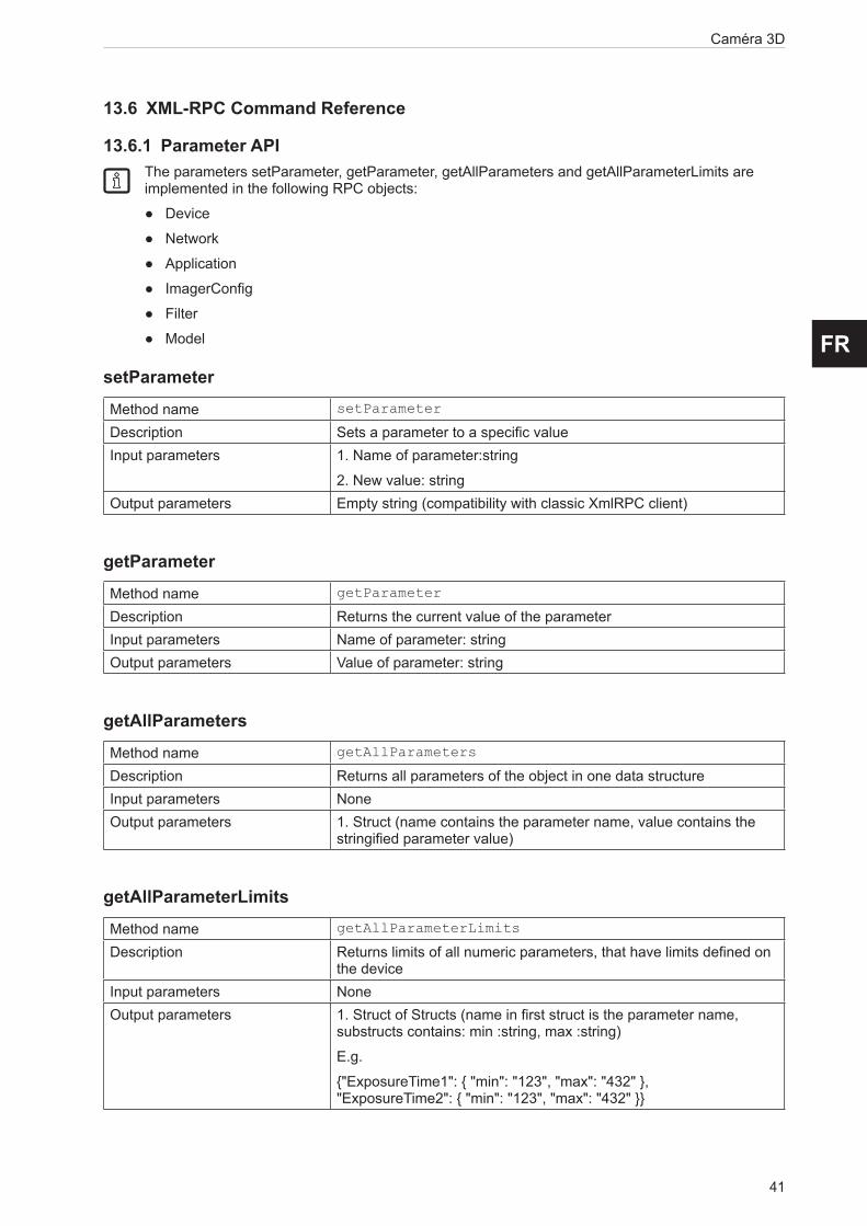
13.6 XML-RPC Command Reference
13.6.1 Parameter APIThe parameters setParameter, getParameter, getAllParameters and getAllParameterLimits are implemented in the following RPC objects:
● Device
● Network
● Application
● ImagerConfig
● Filter
● Model
setParameterMethod name setParameter
Description Sets a parameter to a specific valueInput parameters 1. Name of parameter:string
2. New value: stringOutput parameters Empty string (compatibility with classic XmlRPC client)
getParameterMethod name getParameter
Description Returns the current value of the parameterInput parameters Name of parameter: stringOutput parameters Value of parameter: string
getAllParametersMethod name getAllParameters
Description Returns all parameters of the object in one data structureInput parameters NoneOutput parameters 1. Struct (name contains the parameter name, value contains the
stringified parameter value)
getAllParameterLimitsMethod name getAllParameterLimits
Description Returns limits of all numeric parameters, that have limits defined on the device
Input parameters NoneOutput parameters 1. Struct of Structs (name in first struct is the parameter name,
substructs contains: min :string, max :string)
E.g.
{"ExposureTime1": { "min": "123", "max": "432" }, "ExposureTime2": { "min": "123", "max": "432" }}
Caméra 3D
42
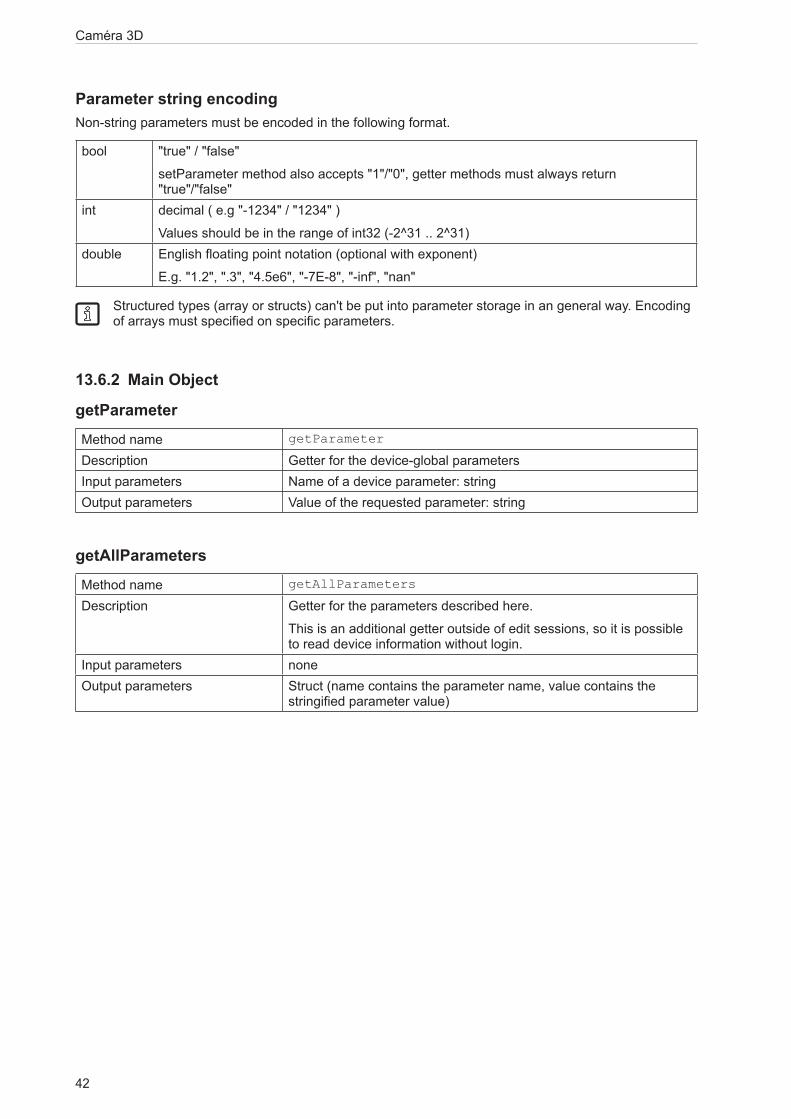
Parameter string encodingNon-string parameters must be encoded in the following format.
bool "true" / "false"
setParameter method also accepts "1"/"0", getter methods must always return "true"/"false"
int decimal ( e.g "-1234" / "1234" )
Values should be in the range of int32 (-2^31 .. 2^31)double English floating point notation (optional with exponent)
E.g. "1.2", ".3", "4.5e6", "-7E-8", "-inf", "nan"
Structured types (array or structs) can't be put into parameter storage in an general way. Encoding of arrays must specified on specific parameters.
13.6.2 Main Object
getParameterMethod name getParameter
Description Getter for the device-global parametersInput parameters Name of a device parameter: stringOutput parameters Value of the requested parameter: string
getAllParametersMethod name getAllParameters
Description Getter for the parameters described here.
This is an additional getter outside of edit sessions, so it is possible to read device information without login.
Input parameters noneOutput parameters Struct (name contains the parameter name, value contains the
stringified parameter value)
43
Caméra 3D
FR
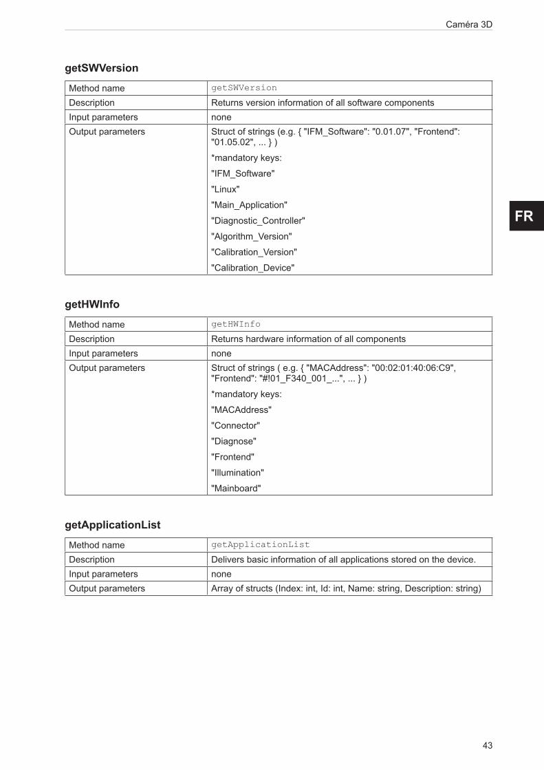
getSWVersionMethod name getSWVersion
Description Returns version information of all software componentsInput parameters noneOutput parameters Struct of strings (e.g. { "IFM_Software": "0.01.07", "Frontend":
"01.05.02", ... } )
*mandatory keys:
"IFM_Software"
"Linux"
"Main_Application"
"Diagnostic_Controller"
"Algorithm_Version"
"Calibration_Version"
"Calibration_Device"
getHWInfoMethod name getHWInfo
Description Returns hardware information of all componentsInput parameters noneOutput parameters Struct of strings ( e.g. { "MACAddress": "00:02:01:40:06:C9",
"Frontend": "#!01_F340_001_...", ... } )
*mandatory keys:
"MACAddress"
"Connector"
"Diagnose"
"Frontend"
"Illumination"
"Mainboard"
getApplicationListMethod name getApplicationList
Description Delivers basic information of all applications stored on the device.Input parameters noneOutput parameters Array of structs (Index: int, Id: int, Name: string, Description: string)

Caméra 3D
44
requestSessionMethod name requestSession
Description Requests a session object for access to the configuration and for changing the device operating mode.
This blocks parallel editing and allows protection of editing with a password.
The ID could optionally be defined by the external system but it must be the defined format (32char "hex").
If it is called with only one parameter, the device will generate a session ID.
The session will start with a default timeout ("SessionTimeout" device parameter), the timeout can be extended by calling "heartbeat".
The device will stay in RUN mode.
If password is disabled on the device, the value given as password parameter is ignored.
Input parameters 1. Password: string
2. Session ID: string (optional)Output parameters Session ID: string
rebootMethod name reboot
Description Reboot system, parameter defines which mode/system will be booted
Input parameters Type of system that should be booted after shutdown: int
0: Productive mode
1: Recovery modeOutput parameters Output: string
systemCommandMethod name systemCommand
Description Performs a generic command on the device.Input parameters 1. Command: string
2. Parameter: stringOutput parameters Output: string
45
Caméra 3D
FR
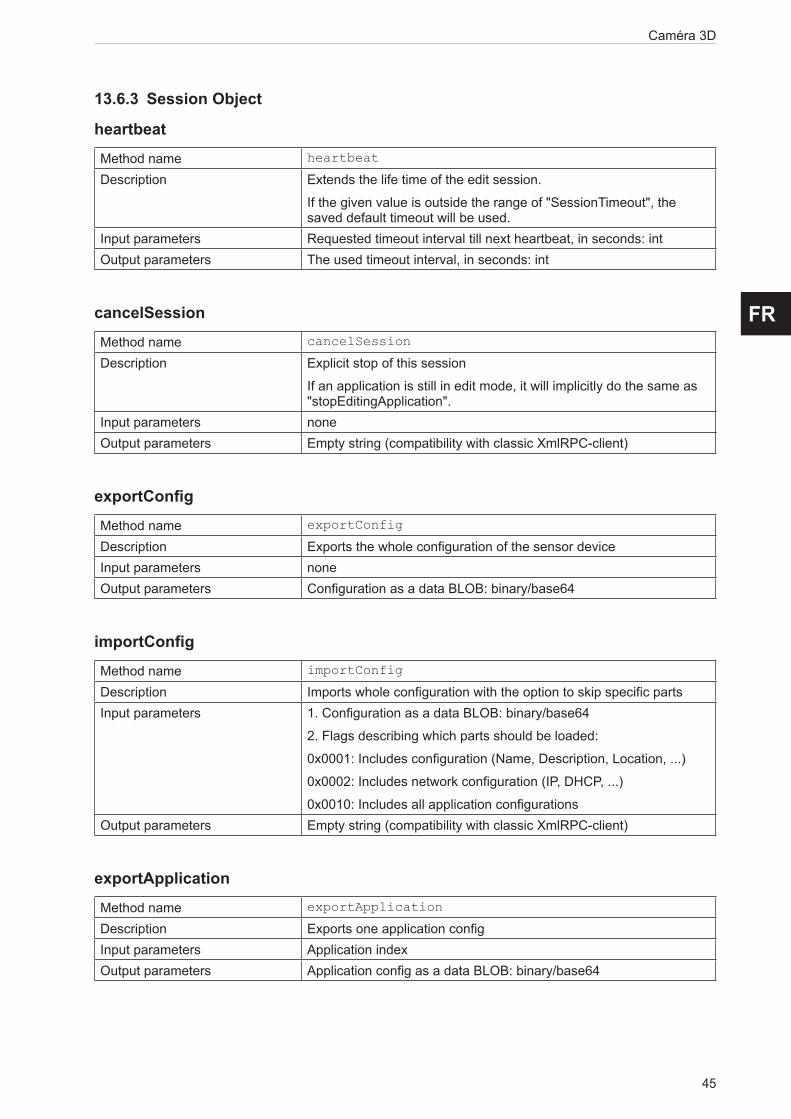
13.6.3 Session Object
heartbeatMethod name heartbeat
Description Extends the life time of the edit session.
If the given value is outside the range of "SessionTimeout", the saved default timeout will be used.
Input parameters Requested timeout interval till next heartbeat, in seconds: intOutput parameters The used timeout interval, in seconds: int
cancelSessionMethod name cancelSession
Description Explicit stop of this session
If an application is still in edit mode, it will implicitly do the same as "stopEditingApplication".
Input parameters noneOutput parameters Empty string (compatibility with classic XmlRPC-client)
exportConfigMethod name exportConfig
Description Exports the whole configuration of the sensor deviceInput parameters noneOutput parameters Configuration as a data BLOB: binary/base64
importConfigMethod name importConfig
Description Imports whole configuration with the option to skip specific partsInput parameters 1. Configuration as a data BLOB: binary/base64
2. Flags describing which parts should be loaded:
0x0001: Includes configuration (Name, Description, Location, ...)
0x0002: Includes network configuration (IP, DHCP, ...)
0x0010: Includes all application configurationsOutput parameters Empty string (compatibility with classic XmlRPC-client)
exportApplicationMethod name exportApplication
Description Exports one application configInput parameters Application indexOutput parameters Application config as a data BLOB: binary/base64
Caméra 3D
46
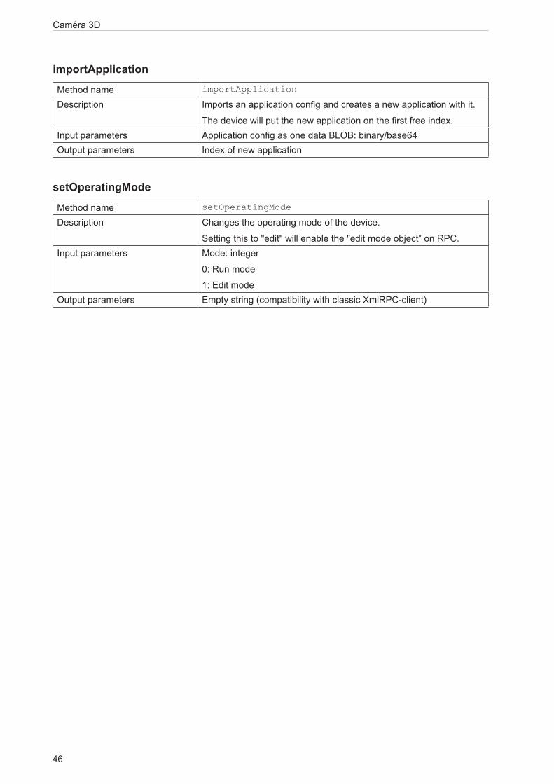
importApplicationMethod name importApplication
Description Imports an application config and creates a new application with it.
The device will put the new application on the first free index.Input parameters Application config as one data BLOB: binary/base64Output parameters Index of new application
setOperatingModeMethod name setOperatingMode
Description Changes the operating mode of the device.
Setting this to "edit" will enable the "edit mode object” on RPC.Input parameters Mode: integer
0: Run mode
1: Edit modeOutput parameters Empty string (compatibility with classic XmlRPC-client)

47
Caméra 3D
FR
13.6.4 Edit Mode Object
factoryResetMethod name factoryReset
Description Resets all configurations to factory settingsInput parameters noneOutput parameters Empty string (compatibility with classic XmlRPC-client)
A factory reset will delete all applications which are saved on the camera.
editApplicationMethod name editApplication
Description Puts a specified application into the edit status.
This will attach an application object to the RPC interface.
The name of the object will be application independent.
This does not change the "ActiveApplication" parameter.Input parameters Application index: intOutput parameters Empty string (compatibility with classic XmlRPC-client)
stopEditingApplicationMethod name stopEditingApplication
Description Tells the device that editing this application was finished.
Unsaved changes are discarded.Input parameters noneOutput parameters Empty string (compatibility with classic XmlRPC-client)
createApplicationMethod name createApplication
Description Creates an "empty" application. The embedded side should initialise all needed parameters and structures.
Input parameters noneOutput parameters Index of new application: int

Caméra 3D
48
copyApplicationMethod name copyApplication
Description Creates a new application by copying the configuration of another application.
The device will generate an ID for the new application and put it on a free index.
Input parameters Index of the application which should be copied: intOutput parameters Index of new application: int
deleteApplicationMethod name deleteApplication
Description Deletes the application from sensor
If the deleted application was the active one, the sensor will have no active application anymore until the user picks one.
Input parameters Index of application: intOutput parameters Empty string (compatibility with classic XmlRPC-client)
moveApplicationsMethod name moveApplications
Description Moves applications to other index.
There must be all applications in the new list, none of them duplicated and no index used twice.
The ID is a fixed value that stays the same as long as the application stays on the sensor.
The index could be changed and is used to address the application via PCIC, XML-RPC and digital IO.
Input parameters Array of structs (Id: int, Index: int)Output parameters Empty string (compatibility with classic XmlRPC-client)
13.6.5 Device Config Object
activatePasswordMethod name activatePassword
Description Sets a password and activates it for the next edit session.
Making this change persistently requires to call "save" on device config.
Input parameters Password: stringOutput parameters Empty string (compatibility with classic XmlRPC-client)

49
Caméra 3D
FR
disablePasswordMethod name disablePassword
Description Disables the password protection.
Making this change persistently requires to call "save" on device config.
Input parameters noneOutput parameters Empty string (compatibility with classic XmlRPC-client)
saveMethod name save
Description Stores current configuration in persistent memory.
If this is not called after changing device parameters (via setParameter), changes will get lost on reboot.
Input parameters noneOutput parameters Empty string (compatibility with classic XmlRPC-client)
Parameters of device configMethods for parameter access are defined here:
Name String (utf8) User-defined name of the device (max. 64 characters).Description String (utf8) User-defined description of the device
(max. 500 characters).ActiveApplication Int
*has limits
Index of active application
This applies only to RUN mode:
* defines the application active on startup (if static-application switching is disabled)
* contains the current active application (could also be changed via PCIC command)
* 0 means no application is activePcicTcpPort Int TCP/IP port for PCIC connections.PcicProtocolVersion Int
*has limits
Sub-protocol of PCIC, see specification of PCIC.
IOLogicType Int
*has limits
Defines logic type of all digital pins.
Allowed values:
0: NPN
1: PNPIODebouncing Bool Applies to all inputsIOExternApplicationSwitch Int
*has limits
Allowed values:
0: off
1: static via I/O
2: pulse driven via I/O
3: pulse driven via trigger
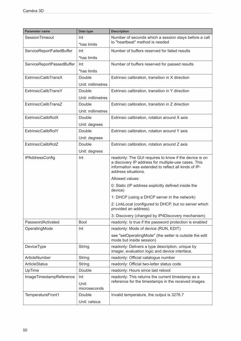
Caméra 3D
50
Parameter name Data type Description
SessionTimeout Int
*has limits
Number of seconds which a session stays before a call to "heartbeat" method is needed
ServiceReportFailedBuffer Int
*has limits
Number of buffers reserved for failed results
ServiceReportPassedBuffer Int
*has limits
Number of buffers reserved for passed results
ExtrinsicCalibTransX Double
Unit: millimetres
Extrinsic calibration, transition in X direction
ExtrinsicCalibTransY Double
Unit: millimetres
Extrinsic calibration, transition in Y direction
ExtrinsicCalibTransZ Double
Unit: millimetres
Extrinsic calibration, transition in Z direction
ExtrinsicCalibRotX Double
Unit: degrees
Extrinsic calibration, rotation around X axis
ExtrinsicCalibRotY Double
Unit: degrees
Extrinsic calibration, rotation around Y axis
ExtrinsicCalibRotZ Double
Unit: degrees
Extrinsic calibration, rotation around Z axis
IPAddressConfig Int readonly: The GUI requires to know if the device is on a discovery IP address for multiple-use cases. This information was extended to reflect all kinds of IP-address situations.
Allowed values:
0: Static (IP address explicitly defined inside the device)
1: DHCP (using a DHCP server in the network)
2: LinkLocal (configured to DHCP, but no server which provided an address)
3: Discovery (changed by IP4Discovery mechanism)PasswordActivated Bool readonly: Is true if the password protection is enabledOperatingMode Int readonly: Mode of device (RUN, EDIT)
see "setOperatingMode" (the setter is outside the edit mode but inside session)
DeviceType String readonly: Delivers a type description, unique by imager, evaluation logic and device interface.
ArticleNumber String readonly: Official catalogue numberArticleStatus String readonly: Official two-letter status codeUpTime Double readonly: Hours since last rebootImageTimestampReference Int
Unit: microseconds
readonly: This returns the current timestamp as a reference for the timestamps in the received images.
TemperatureFront1 Double
Unit: celsius
Invalid temperature, the output is 3276.7

51
Caméra 3D
FR
Parameter name Data type Description
TemperatureFront2 Double
Unit: celsius
Invalid temperature, the output is 3276.7
TemperatureIllu Double
Unit: celsius
readonly: Temperature measured in the device.
Measured on the illumination board.
*has limits: parameters with this marker are listed in the reply of getAllParameterLimits method.
Default values of device config parametersThe default values of the device configuration parameters are:
Name String (utf8) "New sensor"Description String (utf8) ""ActiveApplication Int
*has limits
0
PcicTcpPort Int 50010PcicProtocolVersion Int
*has limits
3
IOLogicType Int
*has limits
1
IODebouncing Bool trueIOExternApplicationSwitch Int
*has limits
0
SessionTimeout Int
*has limits
30
ExtrinsicCalibTransX Double
Unit: millimetres
0.0
ExtrinsicCalibTransY Double
Unit: millimetres
0.0
ExtrinsicCalibTransZ Double
Unit: millimetres
0.0
ExtrinsicCalibRotX Double
Unit: degrees
0.0
ExtrinsicCalibRotY Double
Unit: degrees
0.0
ExtrinsicCalibRotZ Double
Unit: degrees
0.0
IPAddressConfig Int 0PasswordActivated Bool falseOperatingMode Int 0ServiceReportFailedBuffer Int 15ServiceReportPassedBuffer Int 15
For all other device config parameters there are no defined default values because they are either device-dependent (DeviceType, ArticleNumber, ArticleStatus) or volatile (UpTime, ImageTimestampReference).

Caméra 3D
52
Minimum and maximum values of device config parametersThe minimum and maximum values of the device configuration parameters are:
ActiveApplication 0 32PcicProtocolVersion 1 4IOLogicType 0 1IOExternApplicationSwitch 0 3SessionTimeout 5 300
13.6.6 Device/Network Config Object
saveAndActivateConfigMethod name saveAndActivateConfig
Description Reinitialise the network interface so that it uses the configuration which was set by the other RPC methods.
There will be no XMLRPC reply because the network interface is instantly reset.
Input parameters noneOutput parameters Empty string (compatibility with classic XmlRPC-client)
13.6.7 Application Config Object
saveMethod name save
Description Stores current configuration in persistent memory.
This is also be possible if the application is not yet in an "activatable" status.
Input parameters noneOutput parameters Empty string (compatibility with classic XmlRPC-client)
forceTriggerMethod name forceTrigger
Description Executes a software trigger of currently active application.Input parameters noneOutput parameters Empty string (compatibility with classic XmlRPC-client)
ValidateMethod name validate
Description Validates the application. This means it checks if the application can be activated.
Input parameters noneOutput parameters Array of fault structs (Id: int, Text: string)Fault scenarios none

53
Caméra 3D
FR
Parameters of applicationMethods for parameter access are defined here:
Name String (utf8) User-defined name of the application (max. 64 characters).
Description String (utf8) User-defined description of the application (max. 500 characters).
TriggerMode Int
*has limits
Allowed values:
1: free run
2: process interface
3: positive edge
4: negative edge
5: positive and negative edgePcicTcpResultSchema String It defines which images and result data will be sent.
It will also define the order of data elements and additional separators.
Contains single-enabling/disabling of AmplitudeImage, IntensityImage, DistanceImage, XImage, YImage, ZImage, ConfidenceImage, DiagnosticData (→ 13.3.5)
LogicGraph String JSON string describing a flow graph which allows to program the logic between model results and output pins.
Type String Internal useTemplateInfo String A generic JSON storage, where the GUI could store
additional data about the used template GUI (versions and additional parameter decisions).
This data should not be used by the device, it should only be stored on the device.
*has limits: parameters with this marker are listed in the reply of getAllParameterLimits method
Default values of application parametersThe default values of application parameters are:
Name String (utf8) "new application"Description String (utf8) ""TriggerMode Int
*has limits
1
PcicTcpResultSchema String ""LogicGraph String ""Type String "Camera"TemplateInfo String ""
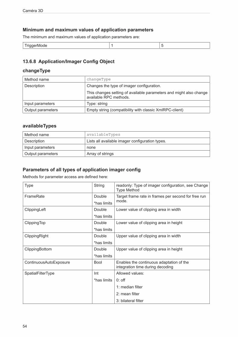
Caméra 3D
54
Minimum and maximum values of application parametersThe minimum and maximum values of application parameters are:
TriggerMode 1 5
13.6.8 Application/Imager Config Object
changeTypeMethod name changeType
Description Changes the type of imager configuration.
This changes setting of available parameters and might also change available RPC methods.
Input parameters Type: stringOutput parameters Empty string (compatibility with classic XmlRPC-client)
availableTypesMethod name availableTypes
Description Lists all available imager configuration types.Input parameters noneOutput parameters Array of strings
Parameters of all types of application imager configMethods for parameter access are defined here:
Type String readonly: Type of imager configuration, see Change Type Method
FrameRate Double
*has limits
Target frame rate in frames per second for free run mode.
ClippingLeft Double
*has limits
Lower value of clipping area in width
ClippingTop Double
*has limits
Lower value of clipping area in height
ClippingRight Double
*has limits
Upper value of clipping area in width
ClippingBottom Double
*has limits
Upper value of clipping area in height
ContinuousAutoExposure Bool Enables the continuous adaptation of the integration time during decoding
SpatialFilterType Int
*has limits
Allowed values:
0: off
1: median filter
2: mean filter
3: bilateral filter

55
Caméra 3D
FR
Parameter name Data type Description
TemporalFilterType Int
*has limits
Allowed values:
0: off
1: temporal mean filter
2: adaptive exponential filterEnableFilterDistanceImage Bool Activates the filter for the distance imageEnableFilterAmplitudeImage Bool Activates the filter for the amplitude imageEnableAmplitudeCorrection Bool Enables the correction of the amplitude valuesEnableRectificationDistanceImage Bool Enables the rectification of the distance imageEnableRectificationAmplitudeImage Bool Enables the rectification of the normalized
amplitude imageExposureTimeList String readonly: A list of all current exposure times
separated by ";"
It should contain 3 values in "*_high" types, 2 values in "*_moderate" types and 1 value in "*_low" types. The list is sorted in ascending order.
MaxAllowedLEDFrameRate Double
readonly
Maximum allowed frame rate for current settings, which complies with the LED duty cycle
EnableFastFrequency Bool Enables rolling evaluation in multi-frequency modes (parameter will be ignored in single-frequency modes)
ClippingCuboid JSON Object describing the clipping cuboid
*has limits: parameters with this marker are listed in the reply of getAllParameterLimits method
Default values of common imager config parametersThe default values of the common imager configuration parameters are:
Type String "under5m_low"FrameRate Double 5.0ContinuousAutoExposure Bool falseSpatialFilterType Int 0TemporalFilterType Int 0EnableFilterDistanceImage Bool trueEnableFilterAmplitudeImage Bool trueEnableAmplitudeCorrection Bool trueEnableRectificationDistanceImage Bool falseEnableRectificationAmplitudeImage Bool false
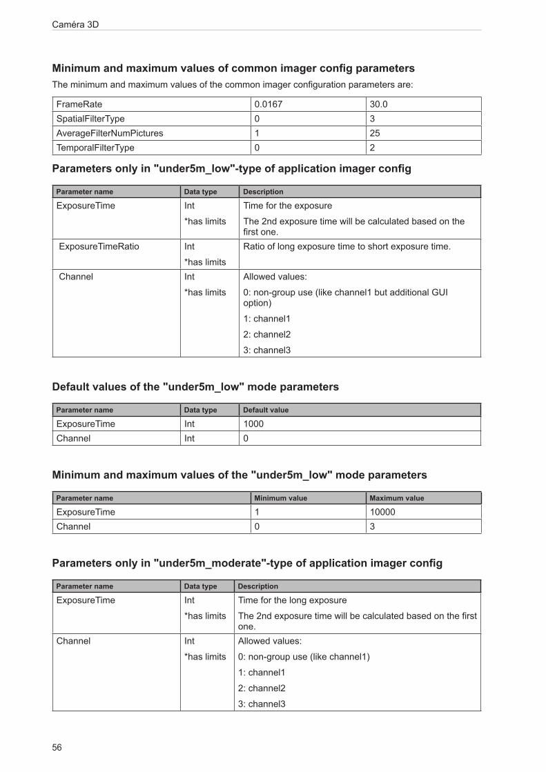
Caméra 3D
56
Minimum and maximum values of common imager config parametersThe minimum and maximum values of the common imager configuration parameters are:
FrameRate 0.0167 30.0SpatialFilterType 0 3AverageFilterNumPictures 1 25TemporalFilterType 0 2
Parameters only in "under5m_low"-type of application imager config
Parameter name Data type Description
ExposureTime Int
*has limits
Time for the exposure
The 2nd exposure time will be calculated based on the first one.
ExposureTimeRatio Int
*has limits
Ratio of long exposure time to short exposure time.
Channel Int
*has limits
Allowed values:
0: non-group use (like channel1 but additional GUI option)
1: channel1
2: channel2
3: channel3
Default values of the "under5m_low" mode parameters
Parameter name Data type Default value
ExposureTime Int 1000Channel Int 0
Minimum and maximum values of the "under5m_low" mode parameters
Parameter name Minimum value Maximum value
ExposureTime 1 10000Channel 0 3
Parameters only in "under5m_moderate"-type of application imager config
Parameter name Data type Description
ExposureTime Int
*has limits
Time for the long exposure
The 2nd exposure time will be calculated based on the first one.
Channel Int
*has limits
Allowed values:
0: non-group use (like channel1)
1: channel1
2: channel2
3: channel3

57
Caméra 3D
FR
Default values of the "under5m_moderate" mode parameters
Parameter name Data type Default value
ExposureTime Int 1000ExposureTimeRatio Int 40Channel Int 0
Minimum and maximum values of the "under5m_moderate" mode parameters
Parameter name Minimum value Maximum value
ExposureTime 1 10000ExposureTimeRatio 2 50Channel 0 3
Parameters only in "under5m_high"-type of application imager configChannel Int
*has limits
Allowed values:
0: non-group use (like channel1 but additional GUI option)
1: channel1
2: channel2
3: channel3
Default values of the "under5m_high" mode parametersChannel Int 0
Minimum and maximum values of the "under5m_high" mode parametersChannel 0 3
Parameters only in "upto30m_low"-type of application imager config
Parameter name Data type Description
ExposureTime Int
*has limits
Time for the long exposure
Channel Int
*has limits
Allowed values:
0: non-group use (like channel1)
1: channel1
2: channel2
3: channel3
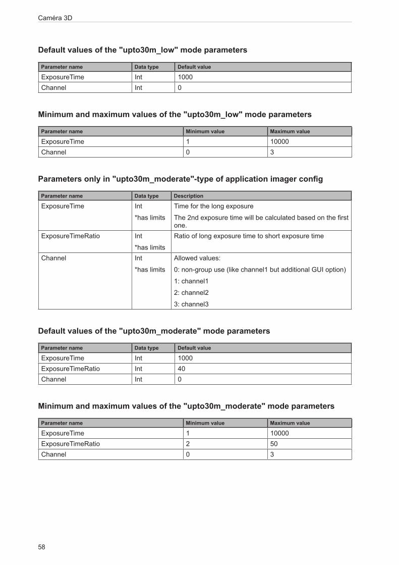
Caméra 3D
58
Default values of the "upto30m_low" mode parameters
Parameter name Data type Default value
ExposureTime Int 1000Channel Int 0
Minimum and maximum values of the "upto30m_low" mode parameters
Parameter name Minimum value Maximum value
ExposureTime 1 10000Channel 0 3
Parameters only in "upto30m_moderate"-type of application imager config
Parameter name Data type Description
ExposureTime Int
*has limits
Time for the long exposure
The 2nd exposure time will be calculated based on the first one.
ExposureTimeRatio Int
*has limits
Ratio of long exposure time to short exposure time
Channel Int
*has limits
Allowed values:
0: non-group use (like channel1 but additional GUI option)
1: channel1
2: channel2
3: channel3
Default values of the "upto30m_moderate" mode parameters
Parameter name Data type Default value
ExposureTime Int 1000ExposureTimeRatio Int 40Channel Int 0
Minimum and maximum values of the "upto30m_moderate" mode parameters
Parameter name Minimum value Maximum value
ExposureTime 1 10000ExposureTimeRatio 2 50Channel 0 3
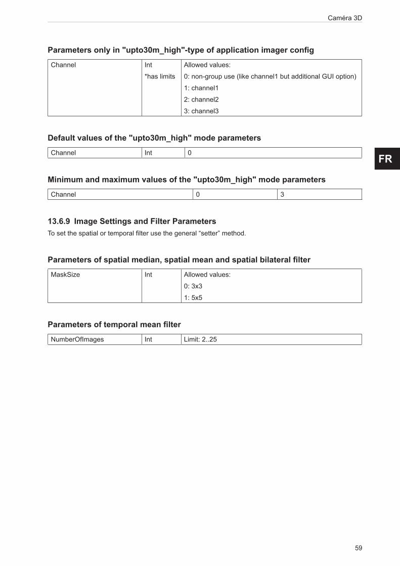
59
Caméra 3D
FR
Parameters only in "upto30m_high"-type of application imager configChannel Int
*has limits
Allowed values:
0: non-group use (like channel1 but additional GUI option)
1: channel1
2: channel2
3: channel3
Default values of the "upto30m_high" mode parametersChannel Int 0
Minimum and maximum values of the "upto30m_high" mode parametersChannel 0 3
13.6.9 Image Settings and Filter ParametersTo set the spatial or temporal filter use the general “setter” method.
Parameters of spatial median, spatial mean and spatial bilateral filterMaskSize Int Allowed values:
0: 3x3
1: 5x5
Parameters of temporal mean filterNumberOfImages Int Limit: 2..25