NEOLYSIS COMMERCIAL SYSTEM EN - Astralpoolpdbdocs.astralpool.com/manuales/...EN_AP_v02_07-02... ·...
40
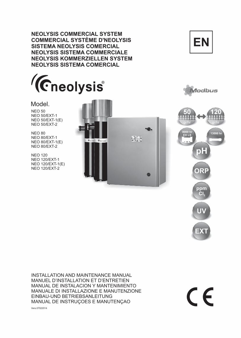
INSTALLATION AND MAINTENANCE MANUAL MANUEL D’INSTALLATION ET D’ENTRETIEN MANUAL DE INSTALACION Y MANTENIMIENTO MANUALE DI INSTALLAZIONE E MANUTENZIONE EINBAU-UND BETRIEBSANLEITUNG MANUAL DE INSTRUÇOES E MANUTENÇAO EN Model. pH ORP 120 50 gr/hr gr/hr 8000 hr EX LS 13000 hr EXT ppm Cl 2 UV Vers.07022014 NEOLYSIS COMMERCIAL SYSTEM COMMERCIAL SYSTÈME D'NEOLYSIS SISTEMA NEOLYSIS COMERCIAL NEOLYSIS SISTEMA COMMERCIALE NEOLYSIS KOMMERZIELLEN SYSTEM NEOLYSIS SISTEMA COMERCIAL NEO 50 NEO 50/EXT-1 NEO 50/EXT-1(E) NEO 50/EXT-2 NEO 80 NEO 80/EXT-1 NEO 80/EXT-1(E) NEO 80/EXT-2 NEO 120 NEO 120/EXT-1 NEO 120/EXT-1(E) NEO 120/EXT-2
Transcript of NEOLYSIS COMMERCIAL SYSTEM EN - Astralpoolpdbdocs.astralpool.com/manuales/...EN_AP_v02_07-02... ·...
INSTALLATION AND MAINTENANCE MANUALMANUEL D’INSTALLATION ET D’ENTRETIENMANUAL DE INSTALACION Y MANTENIMIENTOMANUALE DI INSTALLAZIONE E MANUTENZIONEEINBAU-UND BETRIEBSANLEITUNGMANUAL DE INSTRUÇOES E MANUTENÇAO
EN
Model.
pH
ORP
12050
gr/hrgr/hr
8000 hrEX LS
13000 hr
EXT
ppmCl2
UV
Vers.07022014
NEOLYSIS COMMERCIAL SYSTEMCOMMERCIAL SYSTÈME D'NEOLYSISSISTEMA NEOLYSIS COMERCIALNEOLYSIS SISTEMA COMMERCIALENEOLYSIS KOMMERZIELLEN SYSTEMNEOLYSIS SISTEMA COMERCIAL
NEO 50NEO 50/EXT-1NEO 50/EXT-1(E)NEO 50/EXT-2
NEO 80 NEO 80/EXT-1NEO 80/EXT-1(E)NEO 80/EXT-2
NEO 120 NEO 120/EXT-1NEO 120/EXT-1(E)NEO 120/EXT-2
1
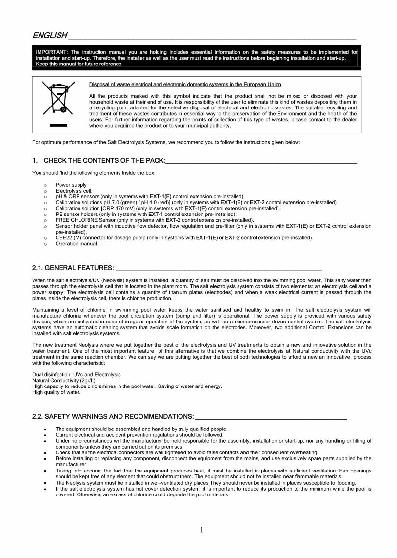
ENGLISH ___________________________________________________________________
IMPORTANT: The instruction manual you are holding includes essential information on the safety measures to be implemented for installation and start-up. Therefore, the installer as well as the user must read the instructions before beginning installation and start-up. Keep this manual for future reference.
Disposal of waste electrical and electronic domestic systems in the European Union All the products marked with this symbol indicate that the product shall not be mixed or disposed with your household waste at their end of use. It is responsibility of the user to eliminate this kind of wastes depositing them in a recycling point adapted for the selective disposal of electrical and electronic wastes. The suitable recycling and treatment of these wastes contributes in essential way to the preservation of the Environment and the health of the users. For further information regarding the points of collection of this type of wastes, please contact to the dealer where you acquired the product or to your municipal authority.
For optimum performance of the Salt Electrolysis Systems, we recommend you to follow the instructions given below: 1. CHECK THE CONTENTS OF THE PACK:___________________________________________________________________ You should find the following elements inside the box:
o Power supply o Electrolysis cell. o pH & ORP sensors (only in systems with EXT-1(E) control extension pre-installed). o Calibration solutions pH 7.0 (green) / pH 4.0 (red)] (only in systems with EXT-1(E) or EXT-2 control extension pre-installed). o Calibration solution [ORP 470 mV] (only in systems with EXT-1(E) control extension pre-installed). o PE sensor holders (only in systems with EXT-1 control extension pre-installed). o FREE CHLORINE Sensor (only in systems with EXT-2 control extension pre-installed). o Sensor holder panel with inductive flow detector, flow regulation and pre-filter (only in systems with EXT-1(E) or EXT-2 control extension
pre-installed). o CEE22 (M) connector for dosage pump (only in systems with EXT-1(E) or EXT-2 control extension pre-installed). o Operation manual.
2.1. GENERAL FEATURES: ________________________________________________________________________ When the salt electrolysis/UV (Neolysis) system is installed, a quantity of salt must be dissolved into the swimming pool water. This salty water then passes through the electrolysis cell that is located in the plant room. The salt electrolysis system consists of two elements: an electrolysis cell and a power supply. The electrolysis cell contains a quantity of titanium plates (electrodes) and when a weak electrical current is passed through the plates inside the electrolysis cell, there is chlorine production. Maintaining a level of chlorine in swimming pool water keeps the water sanitised and healthy to swim in. The salt electrolysis system will manufacture chlorine whenever the pool circulation system (pump and filter) is operational. The power supply is provided with various safety devices, which are activated in case of irregular operation of the system, as well as a microprocessor driven control system. The salt electrolysis systems have an automatic cleaning system that avoids scale formation on the electrodes. Moreover, two additional Control Extensions can be installed with salt electrolysis systems. The new treatment Neolysis where we put together the best of the electrolysis and UV treatments to obtain a new and innovative solution in the water treatment. One of the most important feature of this alternative is that we combine the electrolysis at Natural conductivity with the UVc treatment in the same reaction chamber. We can say we are putting together the best of both technologies to afford a new an innovative process with the following characteristic: Dual disinfection: UVc and Electrolysis Natural Conductivity (2gr/L) High capacity to reduce chloramines in the pool water. Saving of water and energy. High quality of water. 2.2. SAFETY WARNINGS AND RECOMMENDATIONS: _____________________________________________________
The equipment should be assembled and handled by truly qualified people. Current electrical and accident prevention regulations should be followed. Under no circumstances will the manufacturer be held responsible for the assembly, installation or start-up, nor any handling or fitting of
components unless they are carried out on its premises. Check that all the electrical connectors are well tightened to avoid false contacts and their consequent overheating Before installing or replacing any component, disconnect the equipment from the mains, and use exclusively spare parts supplied by the
manufacturer • Taking into account the fact that the equipment produces heat, it must be installed in places with sufficient ventilation. Fan openings
should be kept free of any element that could obstruct them. The equipment should not be installed near flammable materials. • The Neolysis system must be installed in well-ventilated dry places They should never be installed in places susceptible to flooding. If the salt electrolysis system has not cover detection system, it is important to reduce its production to the minimum while the pool is
covered. Otherwise, an excess of chlorine could degrade the pool materials.

2
3. DATASHEET:_____________________________________________________________________________________________________

3
4

5

6

7
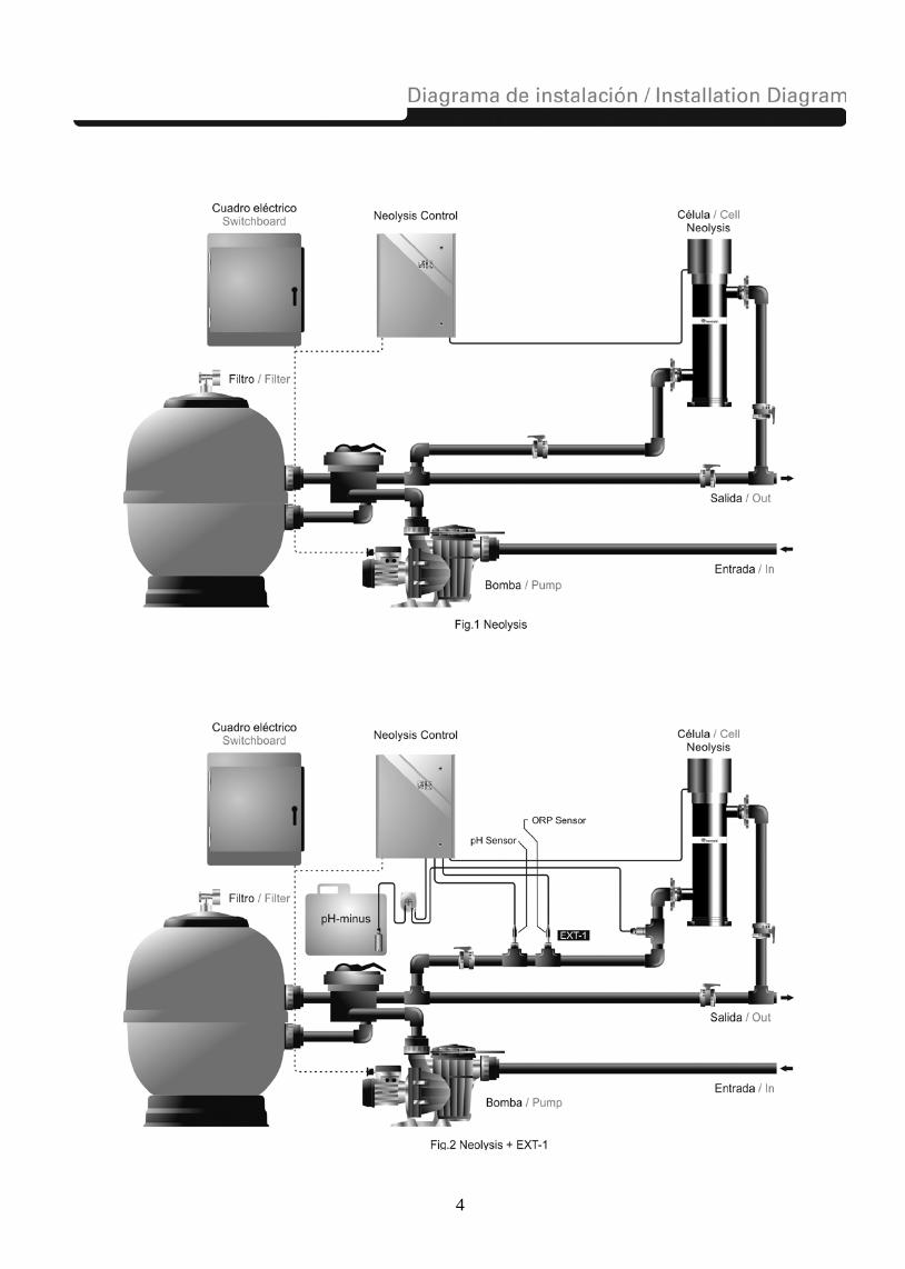
4.INSTALLATION: ___________________________________________________________________________ 4.1. Installation of the power supply Always install the POWER SUPPLY of the salt electrolysis system VERTICALLY on a solid and rigid surface (wall) as shown in the recommended installation diagram (Figs.1,2,3). In order to guarantee a good state of conservation, the POWER SUPPLY should be installed in a well-ventilated dry place. Due to IP degree of the POWER SUPPLY the salt electrolysis system should not be installed outdoors. The POWER SUPPLY should be installed a bit distant from the electrolysis cell so that it cannot accidentally suffer water splashes.
Beware of corrosive atmosphere formation due to pH decreasing solutions (specially, those ones based on hydrochloric acid "HCl"). Do not install the system near to any stores of these chemicals. We strongly recommend the use of chemicals based on sodium bisulphate or diluted sulphuric acid. Power supply must be connected to the electrical control box of the pool, so that the pump and the Electrolysis/UV System are turned on (and off) simultaneously (Figs.1,2,3). 4.2. Installation of the electrolysis cell The electrolysis cell is made of polyethylene in whose interior the electrodes are placed. The electrolysis cell and lamp must be always installed indoors and after the pool filter, and after any other equipment that may be present (heat pumps, control systems, etc.).
The installation of the cell should allow easy access to the installed electrodes by the user (Fig 5). Always install the electrolysis cell VERTICAL in a place of the pipe that can be easily isolated from the rest of the installation by two valves, so that the tasks of maintenance can be carried out with no need of partial or total draining of the swimming pool. Where the cell is installed on a by-pass (recommended option), a valve to regulate the flow must be introduced. Prior to installation, please consider the following commentaries might be considered:
Fig.4
Fig. 5
Fig. 6
Flow direction marked in the cell must be respected. Recirculation system must guarantee minimum flow stated in the Table of Technical Specifications (see Section 9).
The system flow detector (Aux electrode) activates if there is not recirculation (flow) of water through the cell or if flow is very low. If electrolysis gases are not properly removed through the electrolysis cell, the generated gas bubble electrically isolates the auxiliary electrode (electronic detection, gas bubble detector).
WARNING: if the inlet-outlet valves of the electrolysis cell are closed simultaneously, the flow detector (gas detector) will not work correctly, with the consequent risk of cell breakdown. Although this situation is extremely unusual, it can be easily avoided once the equipment has been installed, by locking at opened position the return valve to the swimming pool, so it cannot accidentally be manipulated.

8
4.3. Electrical connection of the electrolysis cell & UV lamps Make the interconnection between the electrolysis cell and the power supply according to the following scheme. Due to relatively high current intensity circulating do not modify or cut either the length or section of the supplied cables without making a previous consultation to an authorized manufacturer distributor. The cable connecting the electrolysis cell and the power supply should never exceed the maximum length recommended in this Manual (see section 9):
MOD.80 | MOD.120

9
MOD.50

10
How to remove UV LP Lamps 1A…8A
11
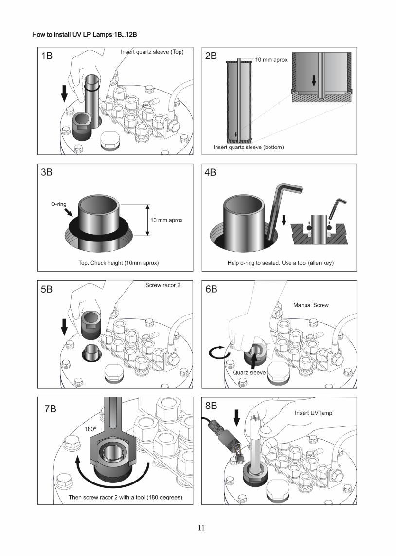
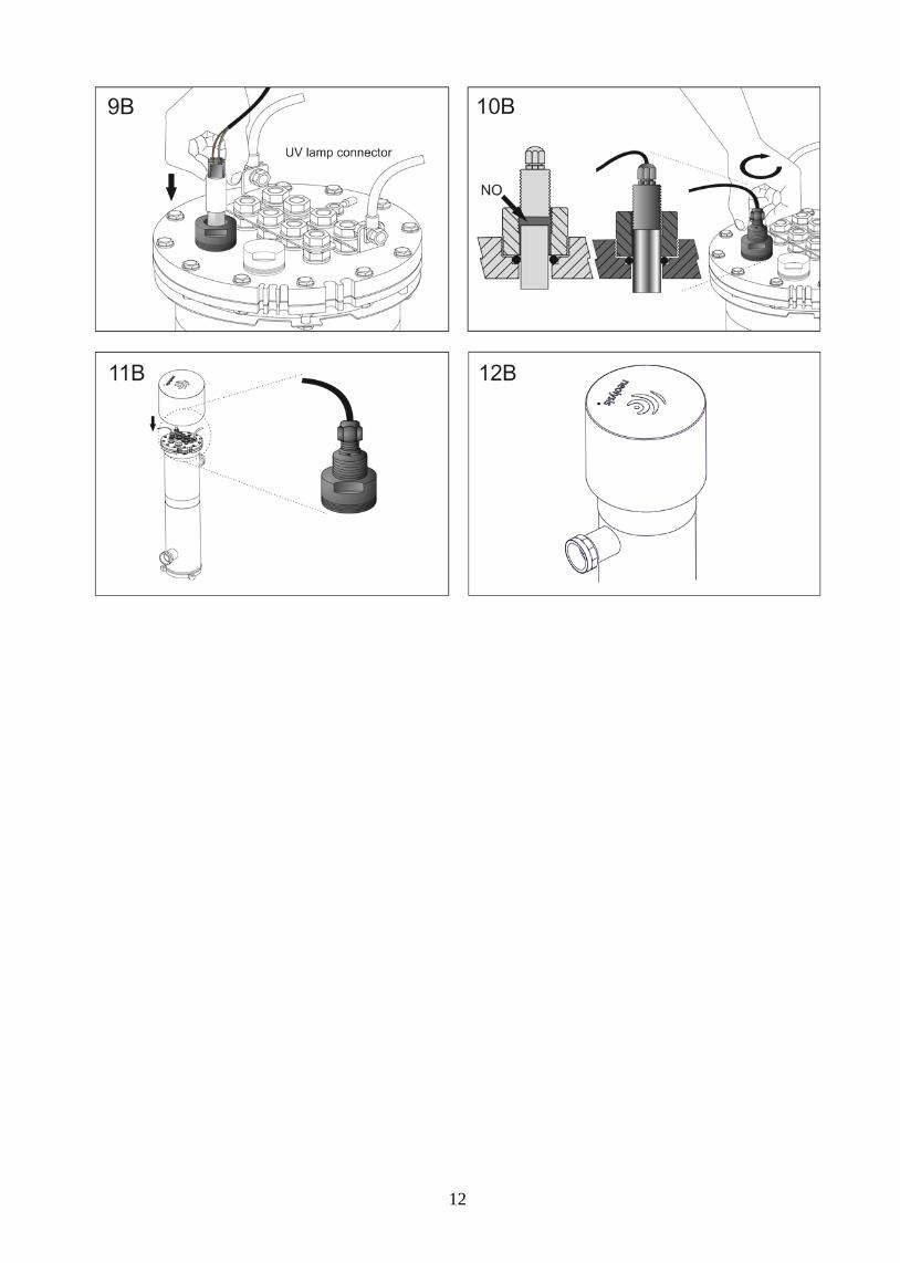
How to install UV LP Lamps 1B…12B
12

13
4.4. Installation of the pH / ORP / ppm sensors 4.4.1 pH EXT-1 & ORP EXT-1 (see fig.2)
Install the pH and ORP electrode holders in the circuit through ½” saddles (not included with the equipment) (Fig. 8)
Insert the electrodes into their corresponding holders. Next, tighten the holder until the electrode is properly fixed.
The electrodes must be installed in the holder so that it is guaranteed that the sensor located in their ends are always submerged in the water circulating through the pipe.
Install always the electrodes vertically or with a maximum inclination of 40º. (Fig. 9).
Connect the pH / ORP sensor provided with the unit to the corresponding BNC connectors located in the unit’s side.
Fig. 8
Fig. 9
4.4.2. pH EXT-1E, EXT-2 (fig 3.1, 3.2) & ORP EXT-1E (see fig.2 )
1. Insert the pH/ORP sensors into their corresponding places of the holder. EXT-1E (Fig. 10a) / EXT-2 (Fig. 10b).
2. To that purpose, loosen the connection screws and insert the sensor into the holder.
3. The probe must be installed in the holder so that it is guaranteed that the sensor located in their ends are always submerged in the water circulating through the pipe.
4. Connect the pH/ORP sensors provided with the unit to the corresponding BNC connector located in the unit’s side.

14
Fig. 10a, Ext-1E (see fig 3.1)
Fig. 10b , Ext-2 (see fig 3.2)

15
4.4.3 ppm EXT-2 (fig 3.2) CL0102 Chlorine sensor is an special sensor to measure the free chlorine concentration in water which could contain isocyanuric acid. Moreover, the probe has low dependence of pH-value.
4.4.3.1. Assembly of the sensor
Fig. 11
Electrolyte can escape by the air exit hole [6] during the manipulation of the membrane cap [9]. Due to electrolyte gel is an aggressive liquid, use of gloves and safety glasses are recommended. In case of contact with skin or eyes, rinse immediately with plenty of water all the affected area.
1. Unscrew the rubber ring of the membrane cap [9] of the sensor. Put the membrane cap on a clean surface. Fill up the membrane cap to the edge with the enclosed electrolyte EEC1/GEL (Fig.12-1). Be careful so that there are no bubbles. (Fig. 12-2).
2. Lift up the transparent cover [7] of the air exit hole [6] using a little screwdriver or similar tool and move it on one side. This
operation leave the air exit hole [6] free. Keep vertically the membrane cap and screw it firmly onto the electrode shaft. Excess electrolyte will escape through the hole [6]. Put the transparent cover [7] in its original position, in order to cover the hole [6].
3. The gasket [3] presents an initial resistance at the beginning of the screwing, so the watertight is guaranteed. Membrane cap [9]
must be screwed, until it be next to the electrode shaft [1]. When the membrane cap [9] is totally screwed, the electrode [5] never must touch the membrane [8]. Membrane could be damaged and could be unusable.
Fig. 12

16
4.4.3.2. Installing the CHLORINE sensor into the sensor holder
1. Insert the CHLORINE sensor supplied into their corresponding places of the holder. (Fig. 13).
2. To that purpose, loosen the connection screws and insert the sensor into the holder.
3. The sensor must be installed in the holder so that it is guaranteed that the sensor located in its ends are always submerged in the water circulating through the pipe. Be careful so that there are no bubbles on the membrane surface.
4. Connect the sensor provided with the unit to the corresponding BNC connector located in the unit’s side.
Fig. 13 EXT-2 (see fig. 3.2)
4.4.3.3 Installing the INDUCTIVE FLOW DETECTOR (EXT-1E / EXT-2) Connect the inductive flow detector to the rectangular connector located on the bottom side of the power supply. (Fig. 14).
Fig. 14
Adjust the water flow passing through the sensor holder with the flow regulator [1], so that the float [2] reaches the height of the inductive flow detector [3]. (Fig. 14.2)
Fig. 14.2
17
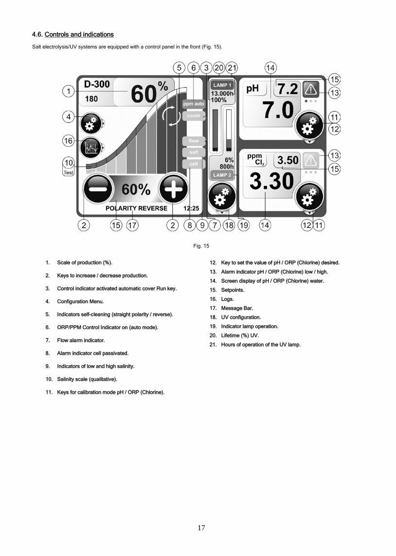
4.6. Controls and indications Salt electrolysis/UV systems are equipped with a control panel in the front (Fig. 15).
Fig. 15
1. Scale of production (%).
2. Keys to increase / decrease production.
3. Control indicator activated automatic cover Run key.
4. Configuration Menu.
5. Indicators self-cleaning (straight polarity / reverse).
6. ORP/PPM Control Indicator on (auto mode).
7. Flow alarm indicator.
8. Alarm indicator cell passivated.
9. Indicators of low and high salinity.
10. Salinity scale (qualitative).
11. Keys for calibration mode pH / ORP (Chlorine).
12. Key to set the value of pH / ORP (Chlorine) desired.
13. Alarm indicator pH / ORP (Chlorine) low / high.
14. Screen display of pH / ORP (Chlorine) water.
15. Setpoints.
16. Logs.
17. Message Bar.
18. UV configuration.
19. Indicator lamp operation.
20. Lifetime (%) UV.
21. Hours of operation of the UV lamp.

18
Besides basic operations, the electrolysis system have a series of input-output signals, enabling the connection of additional external controls. They are located on connector of the power card, inside of the power supply (Fig. 16).
Fig. 16
DESCRIPTION OF TERMINALS:
1.ORP ELECTRODE 2.PH ELECTRODE 3.PPM ELECTRODE (Polarity +,-) 4.INDUCTIVE FLOW DETECTOR(Polarity -,+) 5.FLOW SWITCH.(Contact free potential OPTIONAL) 6.ORP CONTROL EXTERNAL (Contact free potential) 7.COVER SIGNAL(Contact free potential) 8.POOLSTATION CONNECTION 9.pH PUMP CONNECTION (ON/OFF 0.5A/220V) 10.FUSE pH pump(0.5A/220V) 11.RESET DISPLAY 12.BATTERY [5] FLOW -SWITCH (optional, no included ): input for potential-free contact. When the contact connected to this input is open (flow switch open), and the [5] is configured as [FS1c] the electrolysis system switches off due to the flow alarm. Connect the external flow detector wiring to the respective input [5]. Set FS= FS_0 to disable this option.
(5) Configuration: FS= FS_1c , Enabled // FS = FS_0, Disabled
Fig. 17
19
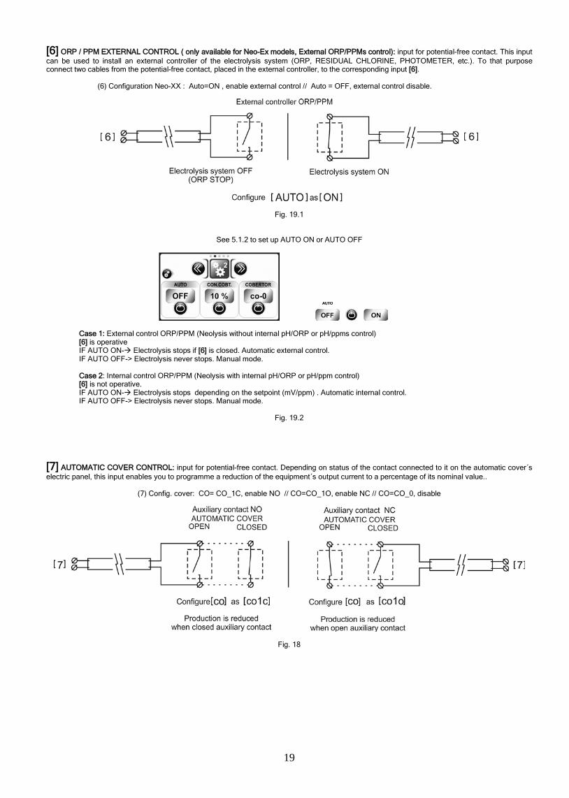
[6] ORP / PPM EXTERNAL CONTROL ( only available for Neo-Ex models, External ORP/PPMs control): input for potential-free contact. This input can be used to install an external controller of the electrolysis system (ORP, RESIDUAL CHLORINE, PHOTOMETER, etc.). To that purpose connect two cables from the potential-free contact, placed in the external controller, to the corresponding input [6].
(6) Configuration Neo-XX : Auto=ON , enable external control // Auto = OFF, external control disable.
Fig. 19.1
See 5.1.2 to set up AUTO ON or AUTO OFF
Case 1: External control ORP/PPM (Neolysis without internal pH/ORP or pH/ppms control) [6] is operative IF AUTO ON- Electrolysis stops if [6] is closed. Automatic external control. IF AUTO OFF-> Electrolysis never stops. Manual mode.
Case 2: Internal control ORP/PPM (Neolysis with internal pH/ORP or pH/ppm control) [6] is not operative. IF AUTO ON- Electrolysis stops depending on the setpoint (mV/ppm) . Automatic internal control. IF AUTO OFF-> Electrolysis never stops. Manual mode.
Fig. 19.2
[7] AUTOMATIC COVER CONTROL: input for potential-free contact. Depending on status of the contact connected to it on the automatic cover´s electric panel, this input enables you to programme a reduction of the equipment´s output current to a percentage of its nominal value..
(7) Config. cover: CO= CO_1C, enable NO // CO=CO_1O, enable NC // CO=CO_0, disable
Fig. 18
20
4.7. Start-up 1. Check that the filter is 100% clean, and ensure that the swimming pool and the installation do not contain copper, iron or algae. Ensure that any heating equipment on the pool is suitable for use in salt water.
2. Ensure that the swimming pool water is balanced, because like that the chlorine produced is used more efficiently and effectively, and ensures that the life of the electrodes is prolonged, as well lower scale build-up in the pool. Water should be maintained within the parameters shown below.
a) pH must be in the range 7.2-7.6
b) Total alkalinity must be in the range 60-120 ppm.
Although the Electrolysis System can operate within a salinity range of 1 – 5 g/l, the minimum recommended level of salt, 1-2 g/l, should be maintained by adding previously NaCl it is necessary. Always use common salt (sodium chloride), without additives like iodides, that is “apt for human consumption”. Never add the salt through the electrolysis cell. Add it directly to the swimming pool or into the balance tank.
3. When adding the salt, and in case the swimming pool is going to be used immediately, carry out a treatment with chlorine. An initial dose of 2 g/m3 of trichloroisocyanuric acid may be added.
4. Prior to starting up the salt chlorinator, disconnect the power supply to the salt chlorinator and run the pump for 24 hours to ensure that the salt is completely dissolved.
5. Next, reconnect the power supply and turn on the salt chlorinator, locating the production level so that free chlorine concentration stays within the recommended range (0.5 - 1.5 ppm).
NOTE: in order to establish the free chlorine level you will need to use a test kit.
6. In outdoor swimming pools it is advisable to maintain a level of 25-30 g/m3 of chlorine stabiliser (cyanuric acid) in the pool. A level of 75 ppm should be never exceeded. This will help to stop the chlorine that is in the water from being destroyed by the sun.

21
5. OPERATION:_______________________________________________________________________________________________
5.1. Electrolysis System 5.1.1. Initialization The configuration and operation functions are organized in a structured programming menu. Once the system is powered on, the system will start always in the state previous to disconnection.
5.1.2. System Programming
To modify the operating parameters of the system, you must enter the programming mode according to the following flowchart

22
5.1.3. System operation: Salt electrolysis system has two operating modes (MANUAL/AUTOMATIC) depending on the set up & installation.
”MANUAL MODE”: AUTO OFF
“AUTOMATIC MODE”: AUTO ON (Internal or External Control, see fig 19.1 + 19,2 & Programming 5.1.2)
5.2. Integrated pH ORP controller (Ext-1 fig 2, Ext-1E fig 3.1, Ext-2 fig 3.2)
The integrated PH/ORP controller is supplied with the following default programming parameters. SET POINT pH=”7.2”
SET POINT ORP=”750 mV”
Control Parameters: pH dosing OFF ON pH >= (SETPOINT + 0.20), HYSTERESIS 5 SECONDS. pH dosing ON OFF pH <= (SETPOINT + 0.10) , HYSTERESIS 1 SECOND. Electrolysis ON OFF mV >= SETPOINT, HYSTERESIS 2 MINUTOS Electrolysis OFF ON mV < SETPOINT, HYSTERESIS 2 SEGUNDOS. IMPORTANT: In order for the pH to be regulated correctly, the Total Alkalinity of the pool water must be maintained in the range 80-150 ppm. Use a pool water test kit to check the Total Alkalinity and manually adjust if necessary.
5.2.1. Connection of the pH / ORP sensors
Connect the PH/ORP electrodes to the corresponding BNC connectors in the right side of the unit. (Fig. 21).
Fig. 21
5.2.2. Connection of the dosage pump
The electrolysis system have a connector on their base for connecting a dosage pump to control the pH of the water in the pool. The dosage pump can be connected through the CEE22 connector supplied for that purpose with the equipment (Fig. 22).
Fig. 22

23
5.2.3. Programming of pH (EXT-1 Fig 2, EXT-1E Fig 3.1, EXT-2 FIG 3.2)
Fig. 23

24
5.2.4. Programming of ORP (EXT-1 FIG. 2, EXT-1E FIG.3.1)

25
IMPORTANT:
1. Before connecting the salt electrolysis system, check pH, alkalinity, stabiliser (cyanuric acid) and free chlorine levels are inside the recommended ranges: pH: 7.2 –7.6. Alkalinity: 80-150 ppm CaCO3. Isocyanuric acid : 0 –30 ppm (ideal value: 20-25 ppm). Free chlorine: 0.5-1.5 ppm.
2. If the addition of chemical products to the pool was necessary to level any of these parameters, disconnect the electrolysis system and leave the pump recirculating during at least 24 hours to guarantee the perfect dissolution of the added products.
3. The ORP controller uses an ORP (mV) electrode to determine the oxidising power of the water, in other words, its destruction capacity of organic matter and pathogens. It should be clearly understood that AN ORP SENSOR DOES NOT MEASURE THE CONCENTRATION OF RESIDUAL CHLORINE IN THE WATER, BUT ITS CAPACITY OF TREATMENT. In summary, higher ORP (mV) values bigger disinfection-treatment grade.
4. If this concept is clear enough, it is easy to understand that two pools with identical levels of residual chlorine in the water, may present ORP values (mV) very different. This fact is due to the oxidising power of the chlorine becomes influenced by other factors, such as pH, stabiliser level (isocyanuric acid), temperature and TDS (total dissolved solids).
5. A good example to illustrate this point is the fact that in a pool without stabiliser (isocyanuric acid) we will need half of residual chlorine that in another with 30 ppm of stabiliser to obtain the same value of ORP (mV). This fact is a consequence of the chlorine stabilisation process by the isocyanuric acid. This product may be added to the water to avoid the fast decomposition of the chlorine due to the action of the sun UV light.
6. In the following table, the behaviour of the ORP value as a function of the variations of the diverse water parameters implied in the water treatment may be observed.
PARAMETER
Free Chlorine + mV - mV Combined Chlorine - mV + mV pH - mV + mV Stabilizer (isocyanuric acid) - mV + mV TDS (total dissolved solids) - mV + mV Temperature + mV - mV
7. In case it was necessary to add stabiliser to the water, it should be taken into account that its employment in concentrations higher than 30-40 ppm produces a very significant decrease of the ORP values (mV) obtained for a given concentration of free chlorine.
8. The ORP setpoint values will fixed in an individualized way in each installation. Nevertheless, a general working range of 700-800 mV may be fixed, for pH values between 7.2 and 7.8, and stabiliser levels (isocyanuric acid) lower than 30 ppm. The previous table might be taken into account when readjusting the set point values of the controller, as these parameters are being modified with time. If the pH or the stabiliser level rise, lower ORP set point values might be selected to maintain the same free chlorine concentration in the water.

26
5.3. Integrated FREE CHLORINE controller (EXT-2 Fig.3.2)
The integrated FREE CHLORINE controller is supplied with the following default programming parameters. SETPOINT = 1.00 ppm PRODUCT = OXIDANT HYSTERESIS= 120 seconds. Control Parameters: Electrolysis ONOFF ppm >= SETPOINT, HYSTERESIS 2 MINUTES. Electrolysis OFFON ppm < SETPOINT, HYSTERESIS 2 SECONDS.
5.3.1. Inicialization The ppm controller requires 1-2 minutes to reach stabilization after flow alarm or switch-on. The message “INIT PROBE” will be displayed.
5.3.2. Programming of PPM

27
5.3.3. Checking ppm controller with ID-CAL
28
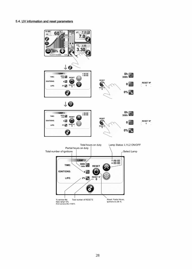
5.4. UV information and reset parameters

29
5.5. Historical / LOG:________________________________________________________________________________________________
Using the LOG. We can access the database machine and know the values that have been obtained on a specific date, or alarms that have appeared.

30
5.6. Alarms and Messages
Alarms
Flow Alarm: The system is provided with a sensor (for detection of gas bubbles inside the cell) that is able to determine whether there is sufficient water flow to ensure proper system operation. If I had not, the system will show us alarm "FLOW." This sensor does not work if the inlet and outlet are closed cell. In this case, if the electrolysis system is up and closed valves will cause an overpressure inside the cell that would cause rupture of the cell. Optionally the system allows the installation of a mechanical flow sensor in the bypass, after the inlet valve, which disconnects the system in case of no flow through the interior of the cell. In systems with EXT-2, this sensor is buying the series can go.
Alarm salt: Added an excess temperature and salt or the salt level is low.
Alarm Cell: Cell is passivated, its life term.
Alarm pH: The pH controller integrated features an alarm that activates when it detects an abnormal value outside the range of pH 6.5 - 8.5. When the controller detects an active alarm stops dosing pump
ORP Alarm: The ORP controller has an alarm that activates when it detects an abnormal value of ORP (mV) (outside the range 650-850 mV). For safety reasons, the controller disconnects the control output when the reading exceeds the upper limit (850 mV).
Alarm CHLORINE: Free Chlorine Controller has an alarm that activates when it detects an abnormal value of free chlorine (ppm) (outside the range 0.3 - 3.5 ppm). For safety reasons, the controller disconnects the control output when the reading exceeds the upper limit (3.5 ppm).
Messages
ORP Auto: The ORP control was activated from the System Setup menu.
Cover: The cover is on.

31
6. MAINTENANCE: ____________________________________________________________________________________________
6.1. Maintenance of the electrolysis cell
The electrolysis cell must be kept in suitable conditions to ensure a long lifetime. This salt chlorination unit has an automatic electrode cleaning system that helps to prevent scale build-up on the electrode surface. If the salt chlorination system is operated in accordance with these instructions, and in particular if the pool water balance is kept within the recommended parameters, it should not be necessary to manually clean the electrodes. However, if the pool water and the salt chlorination system are not maintained in line with these instructions then it may be necessary to manually clean the electrodes following the procedure outlined below:
1. Cut off the 230 Vac unit’s supply.
2. Unscrew the closing nut located at the end where the electrodes are located, and remove the electrode package.
3. Use diluted hydrochloric acid (a part of commercial acid in 10 parts of water), submerging the electrode package in the prepared solution for no more than 10 minutes.
4. NEVER SCRAPE OR SWEEP THE CELL OR THE ELECTRODES.
The electrodes of a salt chlorination system comprise of a titanium sheet coated with a layer of noble metal oxides. The electrolysis processes that take place on their surface produce a progressive wearing down – the electrodes do have a finite life. In order to optimise electrode lifetime, please consider the following aspects:
1. Although all the salt electrolysis units are SELF-CLEANING, a prolonged operation of the system at pH values over 7.6 in waters of high hardness can produce scale formation on the surface of the electrodes. Scaling on the electrodes surface will progressively deteriorate the coating, causing a decrease of lifetime.
2. Manually cleaning/washing the electrodes (as described above) will shorten their life.
3. Prolonged operation at salinity values of less than 0.5 gr/L of sodium chloride will cause a premature deterioration of the electrodes.
4. Frequent use of copper based algaecides will promote the formation of copper deposits on the electrodes, progressively damaging the coating. Remember that chlorine is the best algaecide.
6.2. Salt additions
If “LOW SALT” message appears on system display [4], it is necessary to add salt to the pool. It is possible that the system indicates salt levels below the real ones if the water temperature is less than 20oC or if the electrode package has reached the end of its lifetime. In this case, determine the level of salt in the water and add the amount of salt needed The type of common salt (NaCl) indicated for salt electrolysis should have no additives (anti-clogging agents, iodides) and should be suitable for human consumption. To know the exact level of salt we recommend the use of a portable salinity-temperature meter.
IMPORTANT: a sudden failure in the sensors can result in over-dosing of chlorine or pH regulation product. You should take appropriate security measures to foresee this possibility. Keep in mind that high concentrations of free chlorine using DPD colorimetric test will not show any colour, as the DPD reagent degrades when chlorine levels are too high.
6.3. “PUMP STOP”
Pump Stop, stop pump safety. Safety function available for pH pump.
Using this function we set a maximum time of continuous dosing pump. If after this time not reached pH setpoint stop the pump and the system displays an error message.
By default this mode is enabled from the factory with a time of 60 minutes.
The alarm is canceled ...
6.4. Calibration of the FREE CHLORINE sensor
The controller has an automatic calibration system for the amperometric sensor, which will require to know the free chlorine concentration. Free chlorine concentration at calibration time must be within the range 0.01 to 5.00 ppm, Calibration with too low chlorine levels (< 0.50 ppm) is not recommended.
It is very important to ensure that the chlorine reading at calibration time is stable. For example, we can not calibrate right after chlorine powder has been added to the pool.
The system will not allow the calibration process if the controller has just been connected or if the water flow in the sensor holder is too low or it has just been restored.
A zero point adjustment is not needed for a sensor whose membrane has been changed. If the analyte is not present in the fluid being measured, the reading will be near zero. The zero point is not affected by changes in flow, conductivity, temperature or pH. Reference methods for calibration in ISO 7393-2 standard may be found. The DPD photometric method is usually used to perform this calibration (DPD = N, N-Diethyl-1 ,4-PhenyleneDiamine).

32
ERROR MESSAGES:
If the calibration process is interrupted for whatever reason, the pH-controller will automatically leave the calibration mode if the intervention of the user is not detected in a few seconds. In this case, “E1” indication in green display will appear.
If the pH value detected during the calibration process is very different from the expected one (e.g., defective electrode, etc.), green display will indicate “E2”, not allowing calibration.
If the pH measure is unstable during the calibration process, code “E3” will appear in the display. In addition, the pH-electrode calibration will not be allowed.
6.5. Maintenance of the CHLORINE sensor
If calibration is not possible, because the reading is very low, then the sensor electrode [5] should be sanded with paper supplied in the installation kit (blue paper), and should also proceed to change the membrane and the electrolyte, as described below:
Fig. 33
PROCEDURE:
Use a small screwdriver or similar tool to remove the transparent cover [7] that protects the bleed hole [6], and move to one side (see Figure 12-2), so that the bleed hole [6] is accessible.
Unscrew the head of the membrane [9] from the sensor body [1]. IMPORTANT: never unscrew the head of the membrane [9] without having the bleed hole [6] open, since the vacuum generated could cause damages in the membrane, leaving it unusable.
Use the supplied special sandpaper to clean only the sensor electrode [5]. To do this, place the special sandpaper on a smooth paper, hold it by one corner, and holding the sensor vertically, drag the tip of the sensor on the sandpaper two or three times.
Place a new membrane, if necessary. Fill the head [9] with the electrolyte supplied. Move the transparent cover [6] to one side (see Figure 12-2). Keeping the sensor body [1] vertically, screw the head [9], allowing the excess electrolyte be bleed through the drain hole [6]. Press the transparent cover [7] until it snaps into position again and the bleed hole [6] is closed. Screw the membrane head [9] until it is completely screwed. The gasket [3] offers an initial resistance when the head [9] is screwed, which makes a perfect seal. When the membrane head [9] is completely secured, the sensor electrode [5] should not hit on the membrane [8], since this will cause
damages in the membrane, leaving it unusable. The membrane lifetime will depend greatly on the quality of water, being approximately 1 year used under normal conditions. Should be
avoided all the time an intensive contamination of the membrane. As a rule, we recommend replacing the electrolyte at least once every three months. After changing the membrane and/or the electrolyte, maintain the electrode polarized at least 1 hour before proceeding to re-calibration.
Recalibrate again after about 24 hours of operation.
If the storage or transport of the sensor is necessary, please proceed as follows: Procedure for the storage of the sensor:
o Use a small screwdriver or similar tool to remove the transparent cover [7] that protects the bleed hole [6], and move to one side (see Figure 12-2), so that the bleed hole [6] is accessible.
o Unscrew the membrane head [9] from the sensor body [1]. o Rinse the active parts of the sensor [4,5] with distilled water, removing all traces of electrolyte, and allow to dry. o Once dry, screw the membrane head [9] carefully on the sensor body. The membrane [8] must not touch the sensor electrode [5], since
this will cause damages in the membrane, leaving it unusable. Reuse of the sensor
o Clean the sensor electrode [5] as described above with the special sandpaper provided. o Replace the membrane head [9] with a new one, according to the procedure described above.

33
7. TROUBLESHOOTING:_________________________________________________________________________________________
Any action required to solve possible problems in the equipment should always be performed with the equipment disconnected from the mains. Any problem not indicated in the following list should be solved by a qualified technician.
PROBLEM
SOLUTION
Production indicator always indicates “0” at all production levels
Check electrodes.
Verify connections between power supply and the electrolysis cell.
Check salt concentration.
The power supply is not turned on.
Check the system is properly connected to 230 V/50-60 Hz in the command box of the pump.
Check the estate of the fuse located at the bottom of the power supply.
Free chlorine levels in the water are very low.
Check that the system produces chlorine in pool jets.
Verify that the water Chemicals parameters (pH, combined chlorine, isocyanuric acid, etc.) are correct.
Increase filtering time.
Add chlorine stabilizer (cyanuric acid) until a concentration of 25 – 30 g/m3 is achieved.
pH/ORP controller always show extreme values, or readings are unstable.
The cable of the pH/ORP sensor is damaged. Clean the contacts or replace the cable.
The pH/ORP sensor has an air bubble in the membrane area. Hold the sensor in vertical position. Shake it lightly until the bubble moves up.
Sensor fault. The connection cable is too long or it is too near to sources of electrical interference (motors, etc.). Replace the sensor. Locate the unit nearer to the sensor.
Impossible calibration of the pH/ORP sensor
Polluted or expired calibration solution.
Blocked sensor membrane. Check the membrane is not damaged. Clean the sensor with diluted acid in water, shaking it lightly.
Sensor fault. Replace the sensor.
Slow response of the pH/ORP sensor
Sensor electrostatic ally charged. During the calibration phase, the sensors should not be dried with paper or cloth. Clean it exclusively with water and shake it lightly.
Insufficient renovation of the analyzed water (no flow through the sample point). Ensure that the tip of the sensor is submerged in the water at the sample point, and that no air bubbles are present.
34
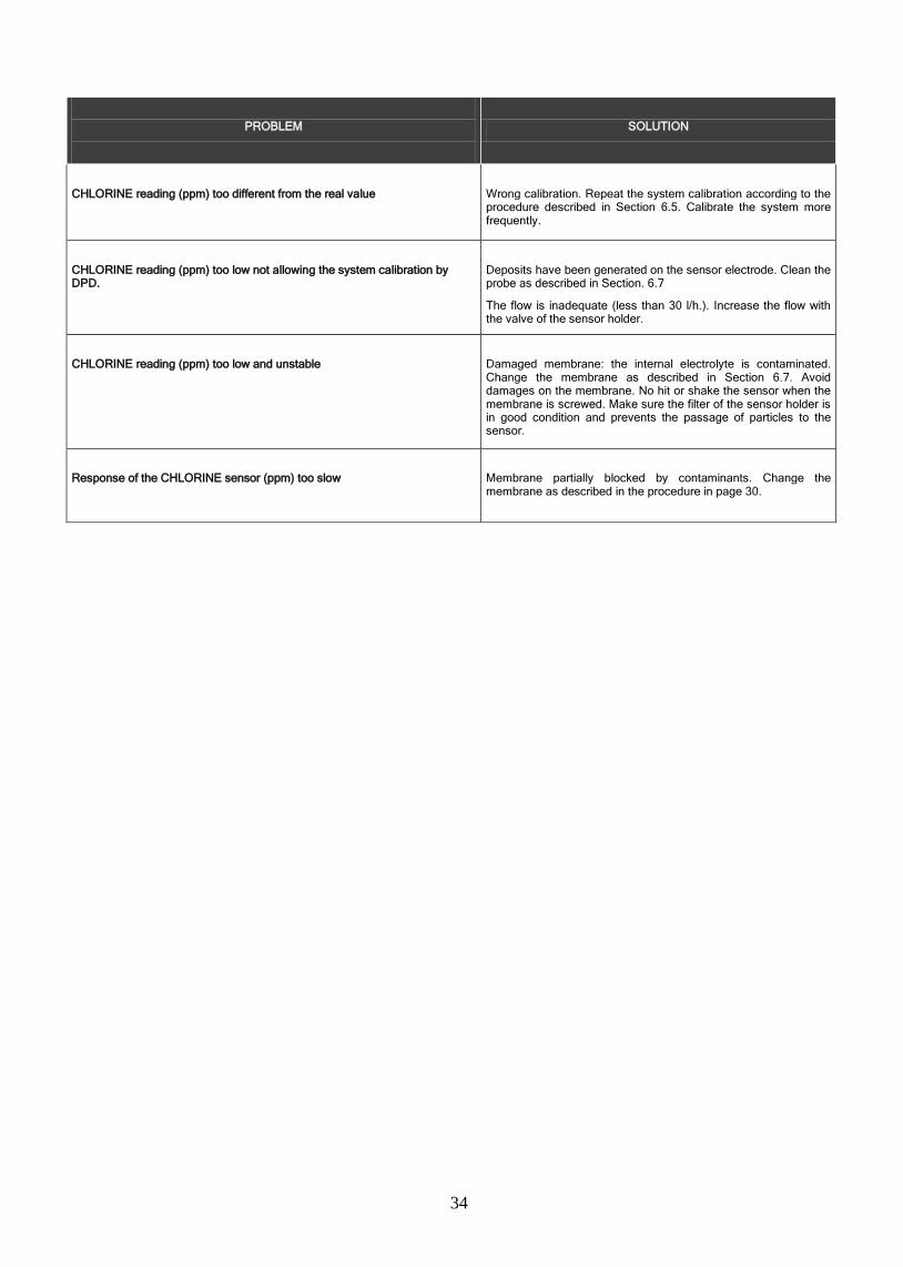
PROBLEM
SOLUTION
CHLORINE reading (ppm) too different from the real value
Wrong calibration. Repeat the system calibration according to the procedure described in Section 6.5. Calibrate the system more frequently.
CHLORINE reading (ppm) too low not allowing the system calibration by DPD.
Deposits have been generated on the sensor electrode. Clean the probe as described in Section. 6.7
The flow is inadequate (less than 30 l/h.). Increase the flow with the valve of the sensor holder.
CHLORINE reading (ppm) too low and unstable
Damaged membrane: the internal electrolyte is contaminated. Change the membrane as described in Section 6.7. Avoid damages on the membrane. No hit or shake the sensor when the membrane is screwed. Make sure the filter of the sensor holder is in good condition and prevents the passage of particles to the sensor.
Response of the CHLORINE sensor (ppm) too slow
Membrane partially blocked by contaminants. Change the membrane as described in the procedure in page 30.

35
8.COMPONENTS_______________________________________________________________________________________________
CONTROL EXTENSIONS
ID CODE DESCRIPTION EXT-1 EXT-1(E) EXT-2 Units
1 2 3 4 5 6 7 8 9
10 10 11 12 12 13
H-035 RX-02 R-028 R-025 R-026 R-027 R-033 R-032 ABRAZ 75 PVC PELEC-ORP S/PMON PELEC-CL S/PMON SENSOR PROX RX-02 CL.01.02 MEM-CL01+G HOLD
PH COMBINED ELECTRODE ORP ELECTRODE PE SENSOR HOLDER 12MM-1/2” BUFFER PH 7.0 125 ML. GREEN BUFFER PH 4.0 125 ML. RED ORP CALIBRATION SOLUTION 470 MV WASHABLE CARTRIDGE FILTER 80 MICRONS CARTRIDGE FILTER FASTENING CLAMP PH+ORP ELECTRODE HOLDER PH+CL ELECTRODE HOLDER INDUCTIVE FLOW SENSOR ORP ELECTRODE FREE CHLORINE SENSOR FREE CHLORINE SENSOR MEMBRANE HEAD
X X
X (2) X X X
X X
X(2) X X X X X X X
X X
X
X (1) X X
X X X
X X
X X
1 1
1 1 1 1 1 1 1 1 1 1 1 1
36
9. TECHNICAL DATA: __________________________________________________________________________________________
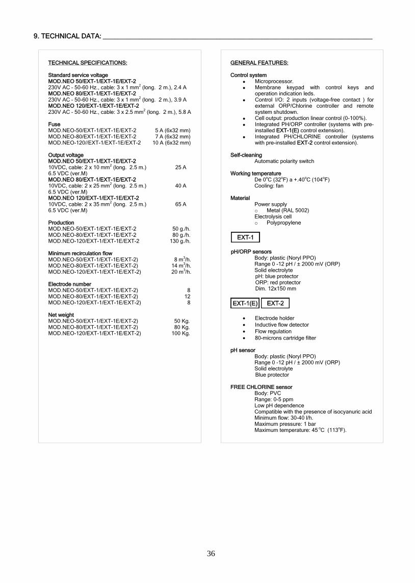
TECHNICAL SPECIFICATIONS: Standard service voltage MOD.NEO 50/EXT-1/EXT-1E/EXT-2 230V AC – 50-60 Hz., cable: 3 x 1 mm2 (long. 2 m.), 2.4 A MOD.NEO 80/EXT-1/EXT-1E/EXT-2 230V AC – 50-60 Hz., cable: 3 x 1 mm2 (long. 2 m.), 3.9 A MOD.NEO 120/EXT-1/EXT-1E/EXT-2 230V AC – 50-60 Hz., cable: 3 x 2.5 mm2 (long. 2 m.), 5.8 A Fuse MOD.NEO-50/EXT-1/EXT-1E/EXT-2 5 A (6x32 mm) MOD.NEO-80/EXT-1/EXT-1E/EXT-2 7 A (6x32 mm) MOD.NEO-120//EXT-1/EXT-1E/EXT-2 10 A (6x32 mm) Output voltage MOD.NEO 50/EXT-1/EXT-1E/EXT-2 10VDC, cable: 2 x 10 mm2 (long. 2.5 m.) 25 A 6.5 VDC (ver.M) MOD.NEO 80/EXT-1/EXT-1E/EXT-2 10VDC, cable: 2 x 25 mm2 (long. 2.5 m.) 40 A 6.5 VDC (ver.M) MOD.NEO 120/EXT-1/EXT-1E/EXT-2 10VDC, cable: 2 x 35 mm2 (long. 2.5 m.) 65 A 6.5 VDC (ver.M) Production MOD.NEO-50/EXT-1/EXT-1E/EXT-2 50 g./h. MOD.NEO-80/EXT-1/EXT-1E/EXT-2 80 g./h. MOD.NEO-120/EXT-1/EXT-1E/EXT-2 130 g./h. Minimum recirculation flow MOD.NEO-50/EXT-1/EXT-1E/EXT-2) 8 m3/h. MOD.NEO-80/EXT-1/EXT-1E/EXT-2) 14 m3/h. MOD.NEO-120/EXT-1/EXT-1E/EXT-2) 20 m3/h. Electrode number MOD.NEO-50/EXT-1/EXT-1E/EXT-2) 8 MOD.NEO-80/EXT-1/EXT-1E/EXT-2) 12 MOD.NEO-120/EXT-1/EXT-1E/EXT-2) 8 Net weight MOD.NEO-50/EXT-1/EXT-1E/EXT-2) 50 Kg. MOD.NEO-80/EXT-1/EXT-1E/EXT-2) 80 Kg. MOD.NEO-120/EXT-1/EXT-1E/EXT-2) 100 Kg.
GENERAL FEATURES: Control system
Microprocessor. Membrane keypad with control keys and
operation indication leds. Control I/O: 2 inputs (voltage-free contact ) for
external ORP/Chlorine controller and remote system shutdown.
Cell output: production linear control (0-100%). Integrated PH/ORP controller (systems with pre-
installed EXT-1(E) control extension). Integrated PH/CHLORINE controller (systems
with pre-installed EXT-2 control extension). Self-cleaning
Automatic polarity switch Working temperature
De 0oC (32oF) a +.40oC (104oF) Cooling: fan
Material
Power supply o Metal (RAL 5002) Electrolysis cell o Polypropylene
pH/ORP sensors
Body: plastic (Noryl PPO) Range 0 -12 pH / ± 2000 mV (ORP) Solid electrolyte pH: blue protector ORP: red protector Dim. 12x150 mm
• Electrode holder • Inductive flow detector • Flow regulation • 80-microns cartridge filter
pH sensor
Body: plastic (Noryl PPO) Range 0 -12 pH / ± 2000 mV (ORP) Solid electrolyte Blue protector
FREE CHLORINE sensor
Body: PVC Range: 0-5 ppm Low pH dependence Compatible with the presence of isocyanuric acid Minimum flow: 30-40 l/h. Maximum pressure: 1 bar Maximum temperature: 45 oC (113oF).

37
10. WARRANTY CONDITIONS:__________________________________________________________________________________
10.1. GENERAL ASPECTS 10.1.1. According to these provisions, the seller guarantees that the guaranteed product is in perfect condition upon delivery. 10.1.2. The Total Warranty period is 2 YEARS. 10.1.3. The Warranty period will be calculated as of delivery to the purchaser. The electrode is covered by a 2-YEAR WARRANTY (or 6.000
hours), which is not extendable. The pH /ORP sensors are covered by a 6-MONTH non-renewable warranty. The free chlorine sensor is covered by a warranty of two years, without extensions, with the exception of the membrane.
10.1.4. Should the Product be faulty and the seller is notified during the Guarantee Period, he shall repair or replace the Product at his own cost wherever he sees fit, unless this is either impossible or out of proportion.
10.1.5. When the Product cannot be repaired or replaced, the buyer may request a proportional price reduction or, if the fault is important enough, rescission of the sales contract.
10.1.6. Parts replaced or repaired pursuant to this warranty shall not extend the warranty period of the original Product, although they shall have their own warranty.
10.1.7. For this warranty to be effective, the buyer shall accredit the date of acquisition and delivery of the Product. 10.1.8. When the buyer alleges a fault in the product over six months after its delivery, he shall accredit the original and existence of the alleged
fault. 10.1.9. This Warranty Certificate does not limit or prejudge consumer rights pursuant to national legislation.
10.2. SPECIFIC CONDITIONS 10.2.1. For this warranty to be effective, the buyer must closely follow the manufacturer’s instructions included in the documentation supplied with
the product, as applicable to each product range and model. 10.2.2. Whenever a schedule is defined for the replacement, maintenance or cleaning of certain product parts or components, the warranty shall
only be valid when said schedule has been correctly followed. 10.3. LIMITATIONS 10.3.1. This warranty shall only be applicable to sales to consumers, with consumer being defined as a person who purchases the product for
other than professional purposes. 10.3.2. No warranty is applicable to normal wear or the product, parts, components and/or fungible or consumable materials (except the
electrode). 10.3.3. The warranty does not cover cases in which the product: (i) has been incorrectly treated; (ii) has been inspected, repaired, maintained or
handled by an unauthorised person; (iii) has been repaired or maintained with non-original parts, or (iv) has been incorrectly installed or started up.
10.3.4. When a faulty product results from incorrect installation or start-up, this warranty shall only be applicable when the installation or start-up forms part of the product contract of sale and had been performed by the seller or under the seller’s responsibility.
10.3.5. Damage or faults due to any of the following causes:
o Bad programming of the system and/or user inadequate calibration of the pH/ORP sensors.
o Operation at salinity values of less than 0.5 gr/L of sodium chloride and/or temperatures lower than 15oC (59oF) or higher than 40oC (104oF).
o Operation at a pH of more than 7.6.
o Use of explicitly unauthorised chemicals.
o Exposure to corrosive environments and/or temperatures of less than 0oC (32oF) or more than 50oC (125oF).

I.D. ELECTROQUIMICA, S.L.
Signature / Qualification:
Signature / Qualification:
Firma / Cargo:
Unterschrift / Qualifizierung:
Firma / Qualifica:
Assinatura / Título:
I.D. ELECTROQUIMICA, S.L.Pol. Ind. Atalayas, Dracma R-19
E-03114 ALICANTE. Spain.
Gaspar Sánchez CanoGerente
01-04-2009
ENFEIDP
PRODUCTSPRODUITSPRODUCTOSPRODOTTIPRODUKTEPRODUTOS
SALT ELECTROLYSIS SYSTEMSYSTÈME D’ÉLECTROLYSE SALINESISTEMA DE ELECTROLISIS DE SALSISTEMA PER L’ELETTROLISI DEL SALESALZ-ELEKTROLYSE-SYSTEMSISTEMA DE ELECTRÓLISE SALINA
DÉCLARATION CE DE CONFORMITÉ
Les produits énumérés ci-dessus sont conformes à: La Directive des Appareils à Basse Tension 73/23/CEE et 93/68/EEC.La Directive de Compatibilité Électromagnétique 89/336/EEC et 92/31/EEC.La Réglementation Européenne EN 61558-1:1999 dans toutes ses modifications.
DECLARATION EC OF CONFORMITY
The products listed above are in compliance with:Low Voltage Directive 73/23/EEC and 93/68/EEC.Electromagnetic Compatibility Directive 89/336/EEC and 92/31/EEC.European Standard EN 61558-1:1999 and all its modifications.
DECLARACION CE DE CONFORMIDAD
Los productos arriba enumerados se hallan conformes con: Directiva de Equipos de Baja Tensión 73/23/CEE y 93/68/EEC.Directiva de Compatibilidad Electromagnética 89/336/EEC y 92/31/EEC.Norma Europea EN 61558-1:1999 en todas sus modificaciones.
DICHIARAZIONE CE DI CONFORMITÀ
I prodotti di cui sopra adempiono alle seguenti direttive: Direttiva per gli Apparecchi a Bassa Tensione 73/23/CEE e 93/68/EEC.Direttiva di Compatibilità elettromagnetica 89/336/EEC e 92/31/EEC.Normativa Europea EN 61558-1:1999 en tutte le sue modifiche.
KONFORMITÄTSERKLÄRUNG CE
Die oben aufgeführten Produkte sind konform mit: Richtlinie für Niederspannungsanlagen 73/23/CEE und 93/68/EEC.Richtlinie zur elektromagnetischen Kompatibilität 89/336/EEC und 92/31/EEC.Europäische Norm EN 61558-1:1999 mit allen Änderungen.
DECLARAÇÃO CE DE CONFORMIDADE
Os produttos relacionados acima estão conformes as: Directiva de Equipamentos de Baixa Tenção 73/23/CEE e 93/68/EEC.Directiva de Compatibilidae Electromagnética 89/336/EEC e 92/31/EEC.Norma Europeia EN 61558-1:1999 e respectivas modificações.
NEO 50 EXNEO 50/EXT-1(E)NEO 50/EXT-2
NEO 80 EXNEO 80/EXT-1(E)NEO 80/EXT-2
NEO 120 EXNEO 120/EXT-1(E)NEO 120/EXT-2

We reserve to change all or part of the articles or contents of this document, without prior noticeNous nous reservons le droit de modifier totalment oru en partie les caracteristiques de nos articles ou le contenu de ce document sans pré avis
Nos reservamos el derecho de cambiar total o parcialmente las características de nuestros artículos o el contenido de eeste documento sin previo avisoCi riservamo il dritto di cambiare totalemente o parzialmente le caratteristiche technique dei nostri prodotti ed il cotenuto di questo docuemntosenza nessum preavviso
Wir behalten uns das recht vor die eigenschatten unserer produkte oder den inhalt dieses prospektes teilweise oder vollstanding, ohne vorherige benachichtigung zu andernReservamo-nos no dereito de alterar, total ou parcialmente as caracteristicas dos nossos artigos ou o coteúdo deste documento sem avisdo prévio.
Made in EC
NIF ES-B03731908MOD80600E102-12