Mit2 72s09 lec08
42
MIT OpenCourseWare http://ocw.mit.edu 2.72 Elements of Mechanical Design Spring 2009 For information about citing these materials or our Terms of Use, visit: http://ocw.mit.edu/terms .
-
Upload
jasim-almuhandis -
Category
Engineering
-
view
17 -
download
0
Transcript of Mit2 72s09 lec08
MIT OpenCourseWare http://ocw.mit.edu
2.72 Elements of Mechanical Design Spring 2009
For information about citing these materials or our Terms of Use, visit: http://ocw.mit.edu/terms.
2.72 Elements of
Mechanical Design
Lecture 08: Flexures

Schedule and reading assignment Quiz
� Today: Bearing layouts (mid-class)� Thursday: Hale 6.1
� Soon: Bolted joint qualifying quiz
Topics � Flexure constraints and bearings… Degrees of Freedom
Reading assignment � Thursday:
• Layton Hale’s thesis – Read 2.6, 2.7, 6.1, skim rest of Chapter 6 • Chapter 7 is cool to look at
� Tuesday: • Read: 8.1, 8.3 – 8.5, 8.7, 8.9 – 8.11 • Skim: 8.6, 8.8, 8.12
© Martin Culpepper, All rights reserved 2

Examples drawn from your lathe
© Martin Culpepper, All rights reserved 3

Mechanisms: Compliant vs. rigid Rigid mechanisms
Images removed due to copyright restrictions. Please see� Sliding joints http://www.physikinstrumente.com/en/primages/pi_m850_tip_i4c_o_eps.jpg
http://www.hexapods.net/images/M850Ani160-1-slow.gif
� 100s of nm resolution
� Large range
� kg load capacity
Compliant mechanisms � Motion from member compliance
� Angstrom resolution θy
� Limited range
� Limited load capacity
z
© Martin Culpepper, All rights reserved 4
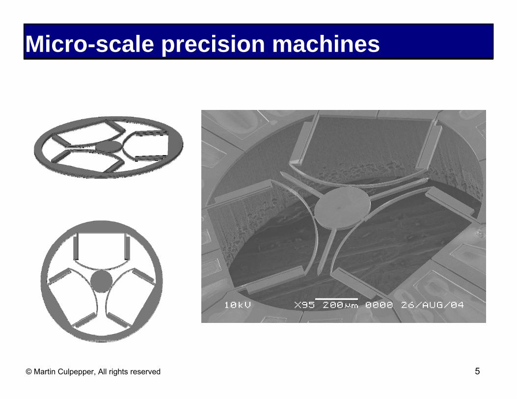
Micro-scale precision machines
© Martin Culpepper, All rights reserved 5
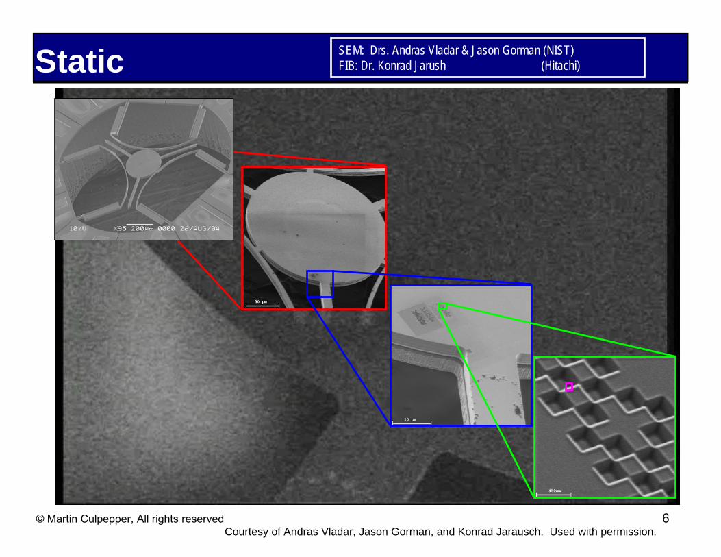
Static SEM: Drs. Andras Vladar & Jason Gorman (NIST) FIB: Dr. Konrad Jarush (Hitachi)
© Martin Culpepper, All rights reserved Courtesy of Andras Vladar, Jason Gorman, and Konrad Jarausch. Used with permission.
6
system
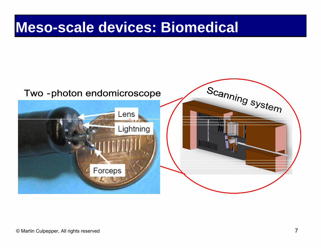
Lighting
Forceps
Lens
Meso-scale devices: Biomedical
Two -photon endomicroscope ScanningTwo -photon endomicroscope
Lighting
Forceps
Lens
Scanning system
© Martin Culpepper, All rights reserved 7
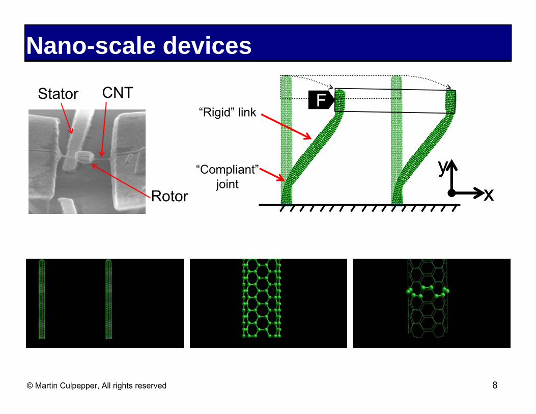
Nano-scale devices
Stator CNT “Rigid” link
“Compliant” joint
Rotor xx yy
F
© Martin Culpepper, All rights reserved 8

Meso-scale precision machines
© Martin Culpepper, All rights reserved 9

TMA ystem
Lighting
Forceps
Lens
Nano-scale devices TMA
Two -photon endomicroscope Scanning sTwo -photon endomicroscope Scanning system
Lighting
Forceps
Lens
Stator CNT “Rigid” link
“Compliant” joint
Rotor xx yy
F
© Martin Culpepper, All rights reserved 10
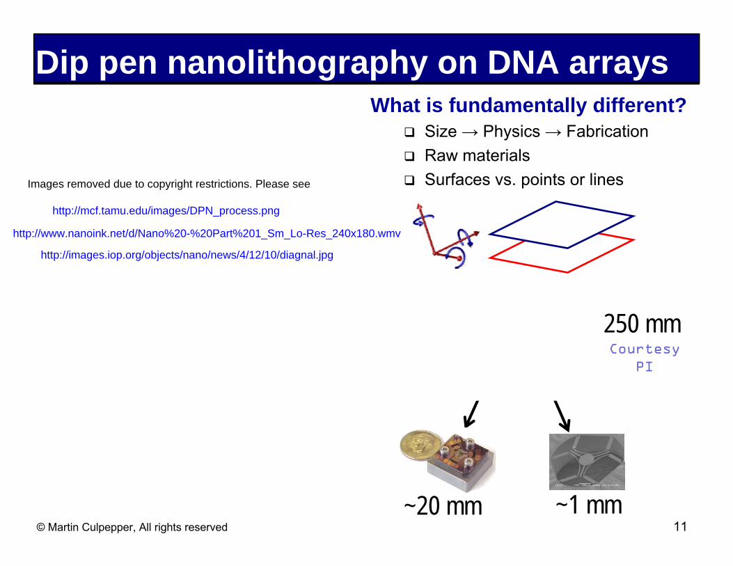
Dip pen nanolithography on DNA arrays What is fundamentally different?
� Size → Physics → Fabrication � Raw materials
Images removed due to copyright restrictions. Please see � Surfaces vs. points or lines
http://mcf.tamu.edu/images/DPN_process.png
http://www.nanoink.net/d/Nano%20-%20Part%201_Sm_Lo-Res_240x180.wmv
http://images.iop.org/objects/nano/news/4/12/10/diagnal.jpg
~20 mm ~1 mm
Courtesy PI
250 mm
© Martin Culpepper, All rights reserved 11
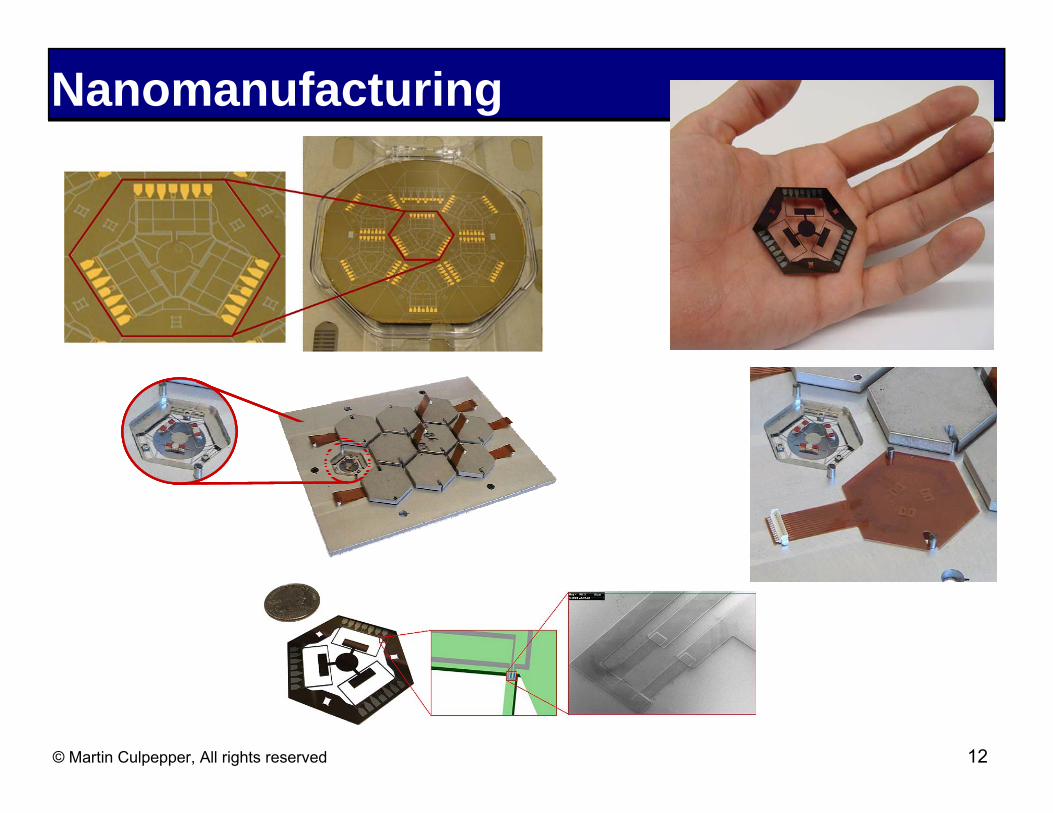
Nanomanufacturing
© Martin Culpepper, All rights reserved 12
Advantages of flexures y
x y
θz
x y
Z
y x
z
θy
y x
z
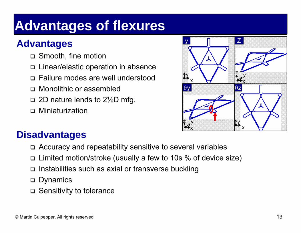
Advantages � Smooth, fine motion
� Linear/elastic operation in absence
� Failure modes are well understood
� Monolithic or assembled
� 2D nature lends to 2½D mfg.� Miniaturization
Disadvantages � Accuracy and repeatability sensitive to several variables � Limited motion/stroke (usually a few to 10s % of device size) � Instabilities such as axial or transverse buckling � Dynamics � Sensitivity to tolerance
© Martin Culpepper, All rights reserved 13

Elastomechanics (σ & ε) relationshipElasticσ = ε ⋅ E
Plastic
MaterialTitanium VAluminum 7075Stainless 316Invar - Annealed
12L14 Steel True Stress-Strain Behavior600
500
400
300
200
100
0
Failure 80
70
60
50
40
30
20
10
00.04 0.05
σ , kpsi
σ , M
Pa
0.00 0.01 0.02 0.03σy/E ε , mm/mm1.00 0.70 0.09 0.19
Young’s modulus, E190 GPa [27.4 Mpsi]
© Martin Culpepper, All rights reserved 14

Important material properties Nominal values
� Modulus � Yield stress � Coefficient of thermal expansion � Thermal diffusivity � Density
Material property ratios Normalized Values
Material σy/E αdiff/αCTE E/ρ Cost Titanium V 1.00 0.14 0.92 3.77 Aluminum 7075 0.70 1.00 1.00 1.00 Stainless 316 Invar - Annealed
0.09 0.19
0.13 0.87
0.94 0.70
3.50 5.21
© Martin Culpepper, All rights reserved 15

Modules Lever Chevron
© Martin Culpepper, All rights reserved 16
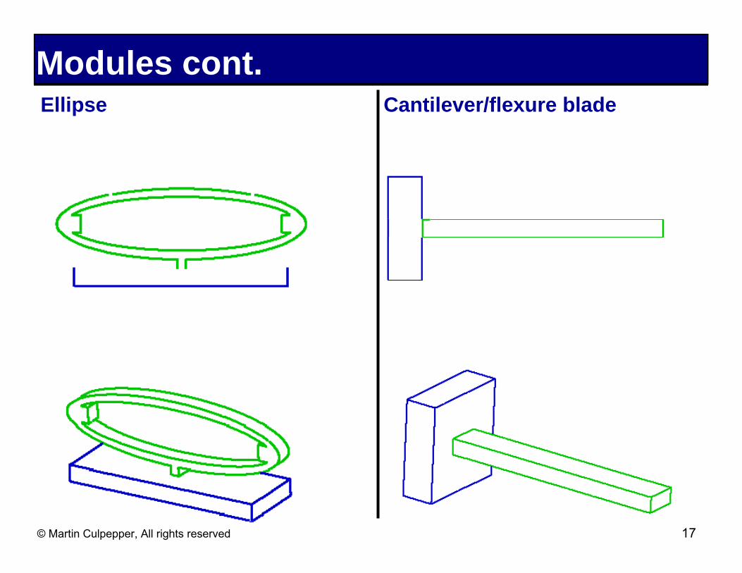
Modules cont. Ellipse Cantilever/flexure blade
© Martin Culpepper, All rights reserved 17

Modules cont. Flexure hinge Torsion
Parallel four bar Double parallel four bar
© Martin Culpepper, All rights reserved 18
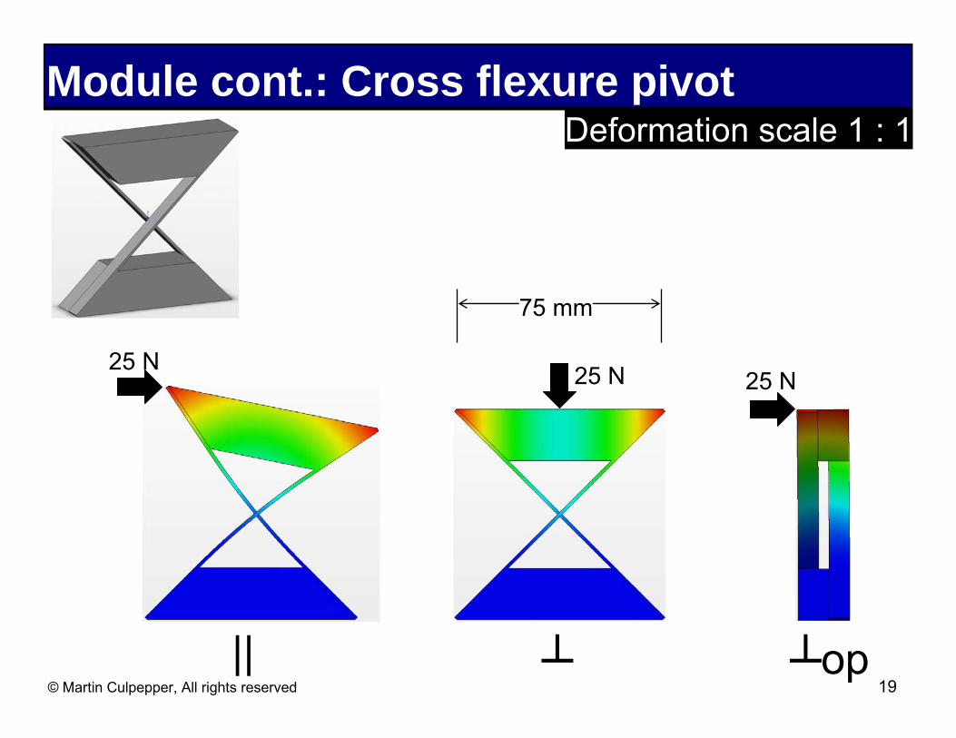
Module cont.: Cross flexure pivot Deformation scale 1 : 1
75 mm
25 N 25 N 25 N
|| ┴ ┴op© Martin Culpepper, All rights reserved 19
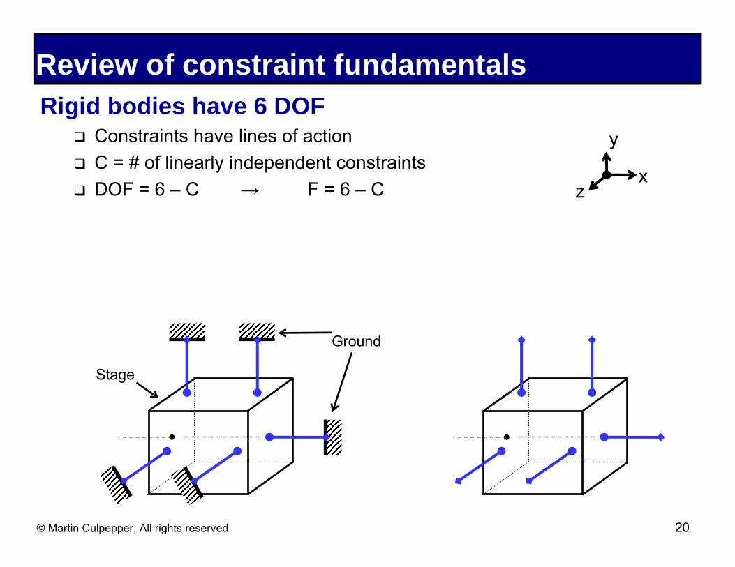
Review of constraint fundamentals Rigid bodies have 6 DOF
� Constraints have lines of action � C = # of linearly independent constraints � DOF = 6 – C → F = 6 – C z
y
x
Stage
Ground
© Martin Culpepper, All rights reserved 20
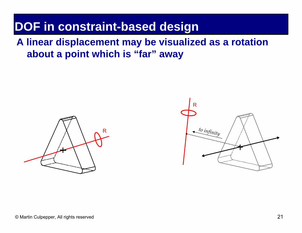
DOF in constraint-based design A linear displacement may be visualized as a rotation
about a point which is “far” away
R
to infinityR
© Martin Culpepper, All rights reserved 21
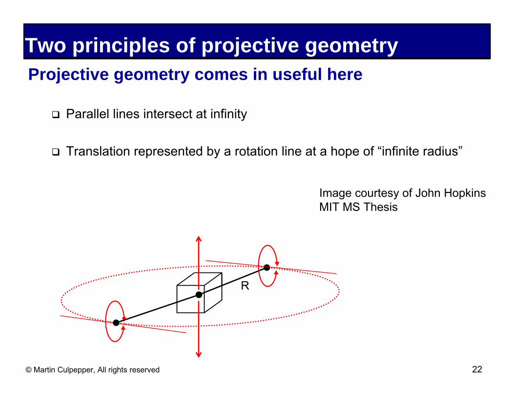
Two principles of projective geometry Projective geometry comes in useful here
� Parallel lines intersect at infinity
� Translation represented by a rotation line at a hope of “infinite radius”
Image courtesy of John Hopkins MIT MS Thesis
R
© Martin Culpepper, All rights reserved 22

Constraint fundamentalsBlanding’s RULE OF COMPLIMENTARY PATTERNS
� Each permissible Freedom (F) is a rotation about a line and each permissible freedom rotation line must intersect each Constraint (C)
Remember these principles of projective geometry � Parallel lines intersect at infinity � Translation represented by a rotation line at a hope of “infinite radius
R= 6 – C = 6 – 5 = 1... so where is it?
C5
C4
C5
C4
C1C1
R1C2C2 C3 C3
© Martin Culpepper, All rights reserved 23

24© Martin Culpepper, All rights reserved
Examples There will be a quiz on this NC
2
y
z x
R2
R1
1
R1
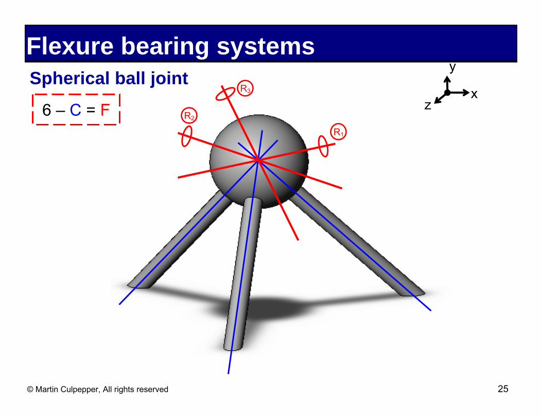
Flexure bearing systems y
Spherical ball joint z
x
R1
R26 – C = F
R3
© Martin Culpepper, All rights reserved 25
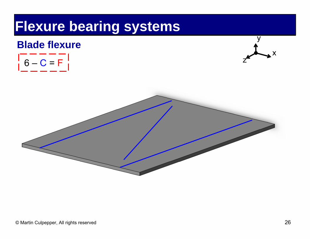
Flexure bearing systems y
Blade flexure x
6 – C = F z
© Martin Culpepper, All rights reserved 26

Flexure bearing systems Parallel guiding mechanism
y
x z6 – C = F
© Martin Culpepper, All rights reserved 27
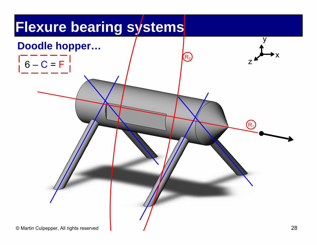
Flexure bearing systems y
Doodle hopper… z
R1
R2 x 6 – C = F
© Martin Culpepper, All rights reserved 28
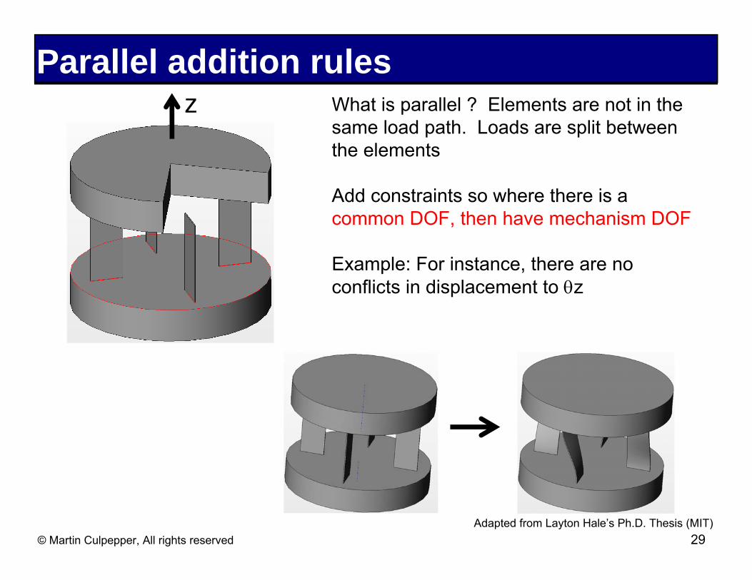
Parallel addition rules z What is parallel ? Elements are not in the
same load path. Loads are split between the elements
Add constraints so where there is a common DOF, then have mechanism DOF
Example: For instance, there are no conflicts in displacement to θz
Adapted from Layton Hale’s Ph.D. Thesis (MIT) © Martin Culpepper, All rights reserved 29

Series addition rules What is series? -Differentiate series by load path -Shared load path = series
Series: Add DOF
Find common constraints
Follow the serial chain
Adapted from: Layton Hale’s Ph.D. Thesis (MIT) © Martin Culpepper, All rights reserved 30
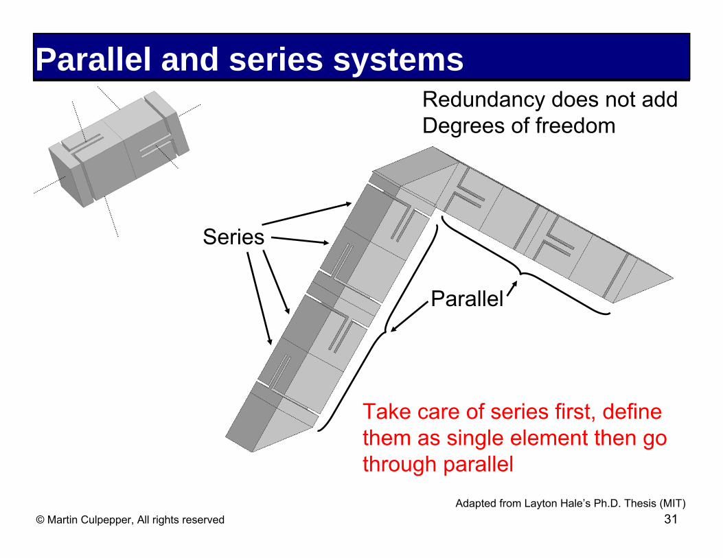
Parallel and series systems
Take care of series first, define them as single element then go through parallel
Series
Parallel
Redundancy does not add Degrees of freedom
Adapted from Layton Hale’s Ph.D. Thesis (MIT) © Martin Culpepper, All rights reserved 31

Accuracy The accuracy of most flexures is sensitive to:
� 1. Small variations in dimensions, e.g. δthickness
� 2. Young’s Modulus (E)
� 3. Time variable errors • Creep • Stress relaxation • Thermal • Dynamic/vibration
© Martin Culpepper, All rights reserved 32

Repeatability Flexures can exhibit Angstrom-level repeatability if:
� Low material hysteresis • Single crystal materials useful
� No dislocation motion • σ << σyield
� Load is repeatable • Magnitude • Direction
� Assembly is correct • No micro-slip • No friction in assembly • No yield during assembly
© Martin Culpepper, All rights reserved 33

Accuracy and repeatability Difficult to obtain without calibration or adjustment
� Geometry
� Materials
� Loading
� Assembly/integration
� Environmental
© Martin Culpepper, All rights reserved 34
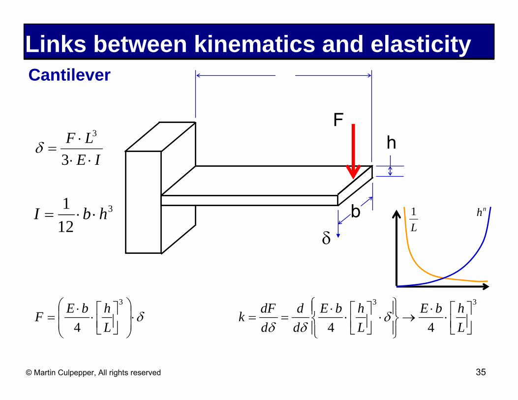
Links between kinematics and elasticity Cantilever L
F F ⋅ L3
δ = 3 ⋅ E ⋅ I
h
b δ
L 1 nh1 3I = ⋅b ⋅ h
12
⎛ E ⋅b ⎡ h ⎤3 ⎞ dF d ⎧⎪E ⋅b ⎡ h ⎤
3 ⎫⎪ E ⋅b ⎡ h ⎤3
F = ⎜⎜
4 ⋅ ⎢⎣ L ⎥⎦ ⎟
⎟ ⋅δ k = dδ
= dδ ⎨ 4
⋅ ⎢⎣ L ⎥⎦ ⋅δ ⎬→
4 ⋅ ⎢⎣ L ⎥⎦⎝ ⎠ ⎩⎪ ⎭⎪
© Martin Culpepper, All rights reserved 35

Links between kinematics and elasticity Cantilever L
FΔL = 0.05 ⋅ L
b δ
h
Δh = 0.05 ⋅ h
Δb = 0.05 ⋅b
k + Δk = E ⋅ (b + Δb)
⋅ ⎡⎢⎣
h + Δh ⎤⎥⎦
3
→ E ⋅b
⋅ ⎡⎢⎣
h ⎤⎥⎦
3
⋅⎛⎜⎜1.05 ⋅ ⎡⎢⎣
1.05 ⎤⎥⎦
3
−1 ⎞⎟⎟ = k ⋅ (1+ 0.42)
4 L − ΔL 4 L ⎝ 0.95 ⎠
Δk = 0.42 ⋅ k
© Martin Culpepper, All rights reserved 36
Fabrication processes: EDM EDM positives
� Accuracy (micrometers) � 3D � Surface finish (sub-micrometers) Image removed due to copyright restrictions. Please see
http://www.physikinstrumente.com/en/about/images/pi_WIREEDMC_i4c_K50_eps.jpg
EDM drawbacks � Time (mm/minute) � Cost
© Martin Culpepper, All rights reserved 37
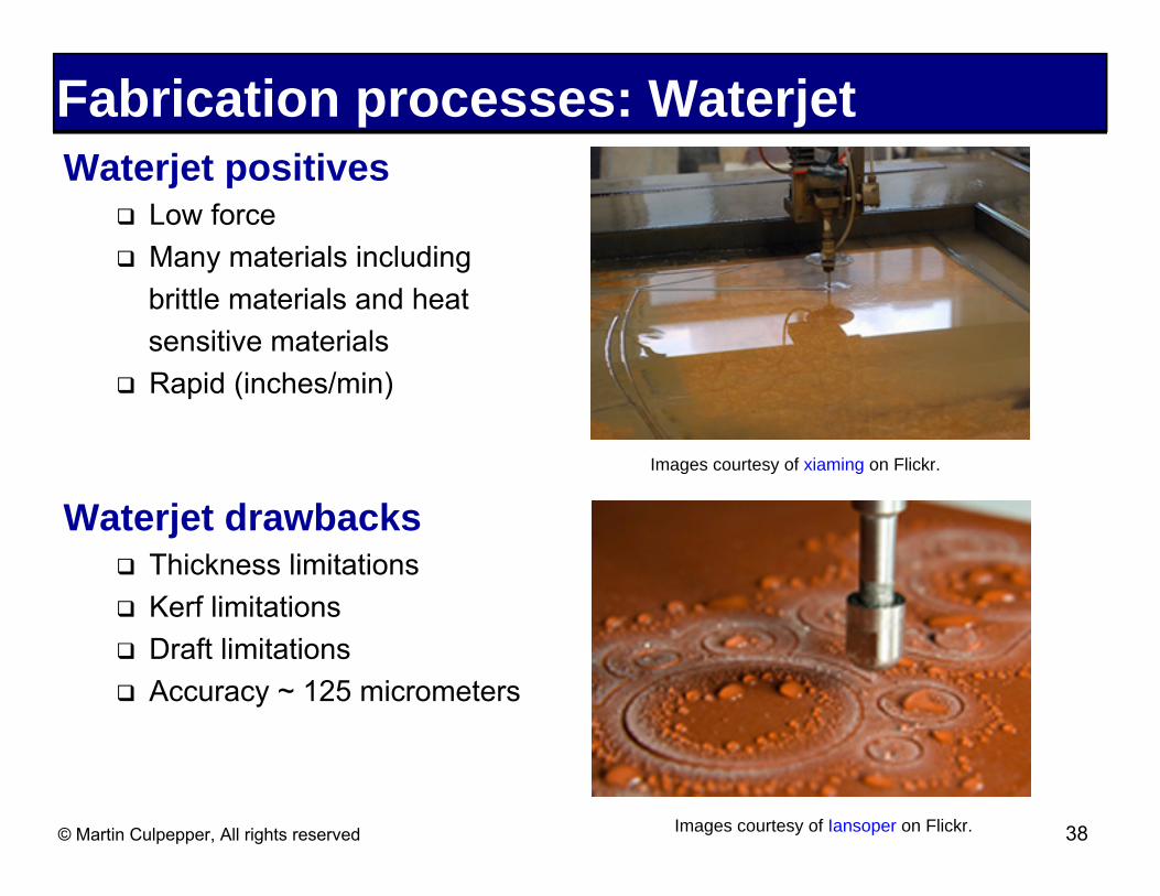
Fabrication processes: Waterjet Waterjet positives
� Low force � Many materials including
brittle materials and heatsensitive materials
� Rapid (inches/min)
Images courtesy of xiaming on Flickr.
Waterjet drawbacks � Thickness limitations
� Kerf limitations
� Draft limitations
� Accuracy ~ 125 micrometers
© Martin Culpepper, All rights reserved Images courtesy of Iansoper on Flickr. 38
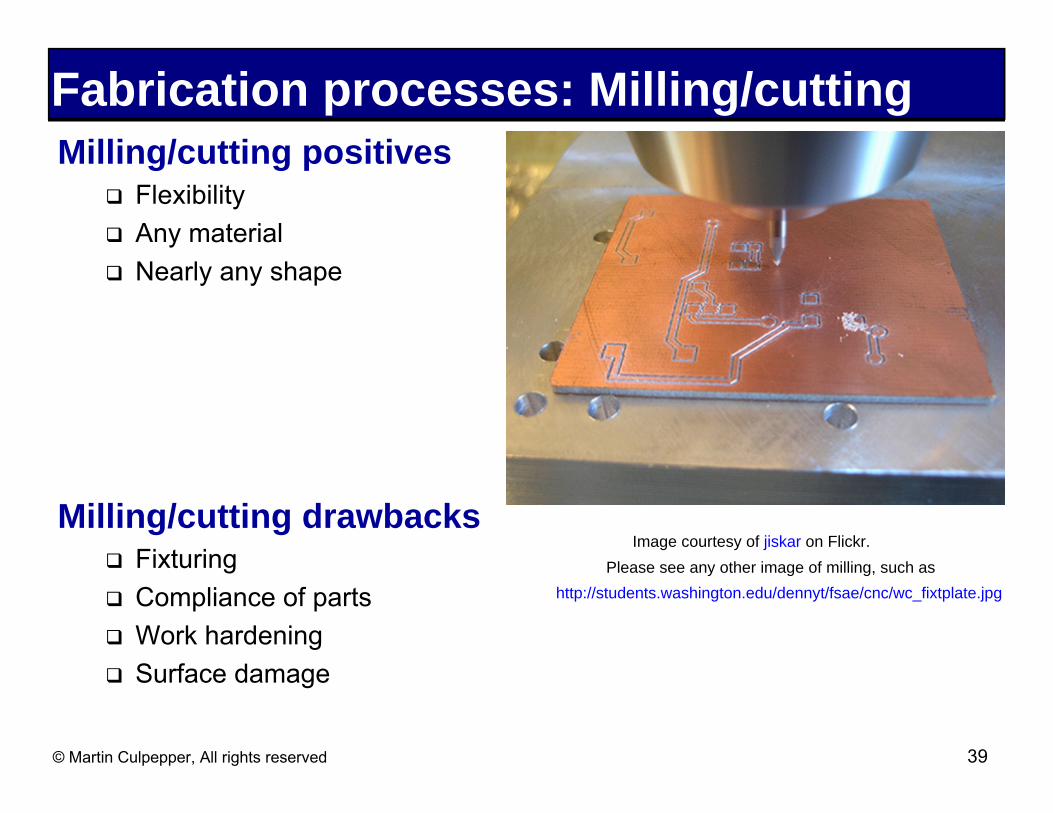
Fabrication processes: Milling/cutting Milling/cutting positives
� Flexibility
� Any material� Nearly any shape
Milling/cutting drawbacks� Fixturing
� Compliance of parts
� Work hardening
� Surface damage
Image courtesy of jiskar on Flickr. Please see any other image of milling, such as
http://students.washington.edu/dennyt/fsae/cnc/wc_fixtplate.jpg
© Martin Culpepper, All rights reserved 39

Fabrication processes: Etching Etching positives
� 2½ D topologies/shapes � Monolithic � Micron-level features
Etching drawbacks � Dimensional control � Scallops
Images removed due to copyright restrictions. Please see:
http://www.ee.ucla.edu/~dejan/ee115c/ucla-graphics/IBM_metal_stack.jpg
http://www.stsystems.com/uploaded_files/1101/images/scallops.jpg
Milanovic, Veljko, et al. "Deep Reactive Ion Etching for Lateral Field Emission Devices." IEEE Electronic Device Letters 21 (June 2000): 271-273.
Milanovic, Veljko, et al. "Micromachining Technology for Lateral Field Emission Devices." IEEE Transactions on Electron Devices 48 (January 2001): 166-173.
Please see 371762. "How Microprocessor Work." February 14, 2009.
YouTube. Accessed October 28, 2009. http://www.youtube.com/watch?v=loMz_l_Fpx4
© Martin Culpepper, All rights reserved 40
Assembly Stress and energy
� Proper thickness of clamps and clamping load distribution � Spring washer provide force source
Fusing � Clamps members should “yield” before flexure � Spring washer provide force source
Surface conformity � Micro-slip is a major cause of hysteresis � Deburring and potting/bonding
Misalignment = systematic errors
© Martin Culpepper, All rights reserved 41
Images removed due to copyright restrictions.Please see Fig. 8.5 and 8.6 in Smith, Stuart.Flexures: Elements of Elastic Mechanisms.Amsterdam, Holland: Gordon & Breach, 2000.