Mise en page 1 - INOGIA · D M L N R P G S T U V W X Y Z a b c D C A E B D C EF A B H G K J...
32
BRANCHE CONNECTEURS AEROMILITAIRES 951 series Normes UTE C 93422 - HE 301 B & MIL-C 26482
Transcript of Mise en page 1 - INOGIA · D M L N R P G S T U V W X Y Z a b c D C A E B D C EF A B H G K J...
15
BRANCHE CONNECTEURS AEROMILITAIRES
951 series Normes UTE C 93422 - HE 301 B & MIL-C 26482
Summary / Sommaire 951
Présentation 1
Caractéristiques techniques 2
Système de référence 3
Positionnement angulaire 4
Arrangements 5
Embases 6-9
Prolongateurs 10-11
Fiches 11
Embases pour circuits imprimés 13
Accessoires 14-15
Modes de fixation 17
Capuchons 18-19
Contacts et outillages 20-23
Caractéristiques techniques hermétiques 24
Système de référence hermétique 25
Embases hermétiques 26
Traversées de cloison hermétiques 27
Joint plat 29
Introduction 1
Technical characteristics 2
Part-numbering system 3
Key orientation 4
Arrangements 5
Receptacles 6-9
Cable connecting receptacles 10-11
Plugs 11
Receptacles for printed circuit boards 13
Accessories 14-15
Mounting styles 17
Protective covers 18-19
Contacts and tools 20-23
Hermetic technical characteristics 24
Hermetic part-numbering system 25
Hermetic receptacles 26
Hermetic T.B.F. 27
Panel seal 29
Présentation / Introduction 951
1
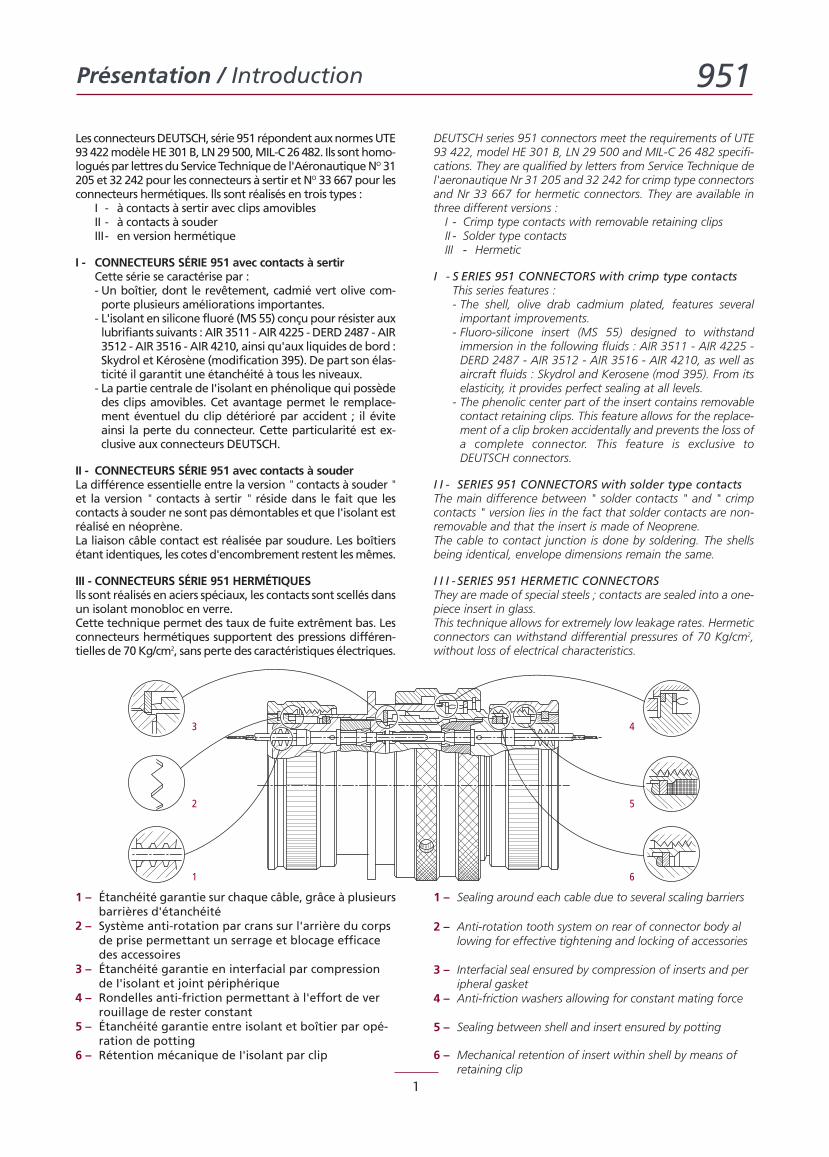
1 – Étanchéité garantie sur chaque câble, grâce à plusieursbarrières d'étanchéité
2 – Système anti-rotation par crans sur l'arrière du corpsde prise permettant un serrage et blocage efficacedes accessoires
3 – Étanchéité garantie en interfacial par compressionde I'isolant et joint périphérique
4 – Rondelles anti-friction permettant à l'effort de verrouillage de rester constant
5 – Étanchéité garantie entre isolant et boîtier par opé-ration de potting
6 – Rétention mécanique de I'isolant par clip
1 – Sealing around each cable due to several scaling barriers
2 – Anti-rotation tooth system on rear of connector body allowing for effective tightening and locking of accessories
3 – Interfacial seal ensured by compression of inserts and peripheral gasket
4 – Anti-friction washers allowing for constant mating force
5 – Sealing between shell and insert ensured by potting
6 – Mechanical retention of insert within shell by means ofretaining clip
1
2
3
6
5
4
Les connecteursDEUTSCH, série 951 répondentauxnormesUTE93422modèleHE301B, LN29500,MIL-C26482. Ils sonthomo-loguéspar lettresduServiceTechniquede l'AéronautiqueNO 31205 et 32 242 pour les connecteurs à sertir et NO 33 667 pour lesconnecteurs hermétiques. lls sont réalisés en trois types :
I - à contacts à sertir avec clips amoviblesII - à contacts à souderIII- en version hermétique
I - CONNECTEURS SÉRIE 951 avec contacts à sertirCette série se caractérise par :- Un boîtier, dont le revêtement, cadmié vert olive com-porte plusieurs améIiorations importantes.- L'isolant en silicone fluoré (MS 55) conçupour résister auxlubrifiants suivants : AIR 3511 -AIR 4225 -DERD2487 -AIR3512 - AIR 3516 - AIR 4210, ainsi qu'aux liquides de bord :Skydrol et Kérosène (modification 395). De part son élas-ticité il garantit une étanchéité à tous les niveaux.- La partie centrale de I'isolant en phénolique qui possèdedes clips amovibles. Cet avantage permet le remplace-ment éventuel du clip détérioré par accident ; il éviteainsi la perte du connecteur. Cette particularité est ex-clusive aux connecteurs DEUTSCH.
II - CONNECTEURS SÉRIE 951 avec contacts à souderLa différence essentielle entre la version " contacts à souder "et la version " contacts à sertir " réside dans le fait que lescontacts à souder ne sont pas démontables et que I'isolant estréalisé en néoprène.La liaison câble contact est réalisée par soudure. Les boîtiersétant identiques, les cotes d'encombrement restent lesmêmes.
III - CONNECTEURS SÉRIE 951 HERMÉTIQUESlls sont réalisés en aciers spéciaux, les contacts sont scellés dansun isolant monobloc en verre.Cette technique permet des taux de fuite extrêment bas. Lesconnecteurs hermétiques supportent des pressions différen-tielles de 70Kg/cm2, sans perte des caractéristiques électriques.
DEUTSCH series 951 connectors meet the requirements of UTE93 422, model HE 301 B, LN 29 500 and MIL-C 26 482 specifi-cations. They are qualified by letters from Service Technique del'aeronautique Nr 31 205 and 32 242 for crimp type connectorsand Nr 33 667 for hermetic connectors. They are available inthree different versions :
I - Crimp type contacts with removable retaining clipsII - Solder type contactsIII - Hermetic
I - S ERIES 951 CONNECTORS with crimp type contactsThis series features :- The shell, olive drab cadmium plated, features severalimportant improvements.
- Fluoro-silicone insert (MS 55) designed to withstandimmersion in the following fluids : AIR 3511 - AIR 4225 -DERD 2487 - AIR 3512 - AIR 3516 - AIR 4210, as well asaircraft fluids : Skydrol and Kerosene (mod 395). From itselasticity, it provides perfect sealing at all levels.
- The phenolic center part of the insert contains removablecontact retaining clips. This feature allows for the replace-ment of a clip broken accidentally and prevents the loss ofa complete connector. This feature is exclusive toDEUTSCH connectors.
I I - SERIES 951 CONNECTORS with solder type contactsThe main difference between " solder contacts " and " crimpcontacts " version lies in the fact that solder contacts are non-removable and that the insert is made of Neoprene.The cable to contact junction is done by soldering. The shellsbeing identical, envelope dimensions remain the same.
I I I - SERIES 951 HERMETIC CONNECTORSThey are made of special steels ; contacts are sealed into a one-piece insert in glass.This technique allows for extremely low leakage rates. Hermeticconnectors can withstand differential pressures of 70 Kg/cm2,without loss of electrical characteristics.
Caractéristiques techniques / Technical characteristics 951
2
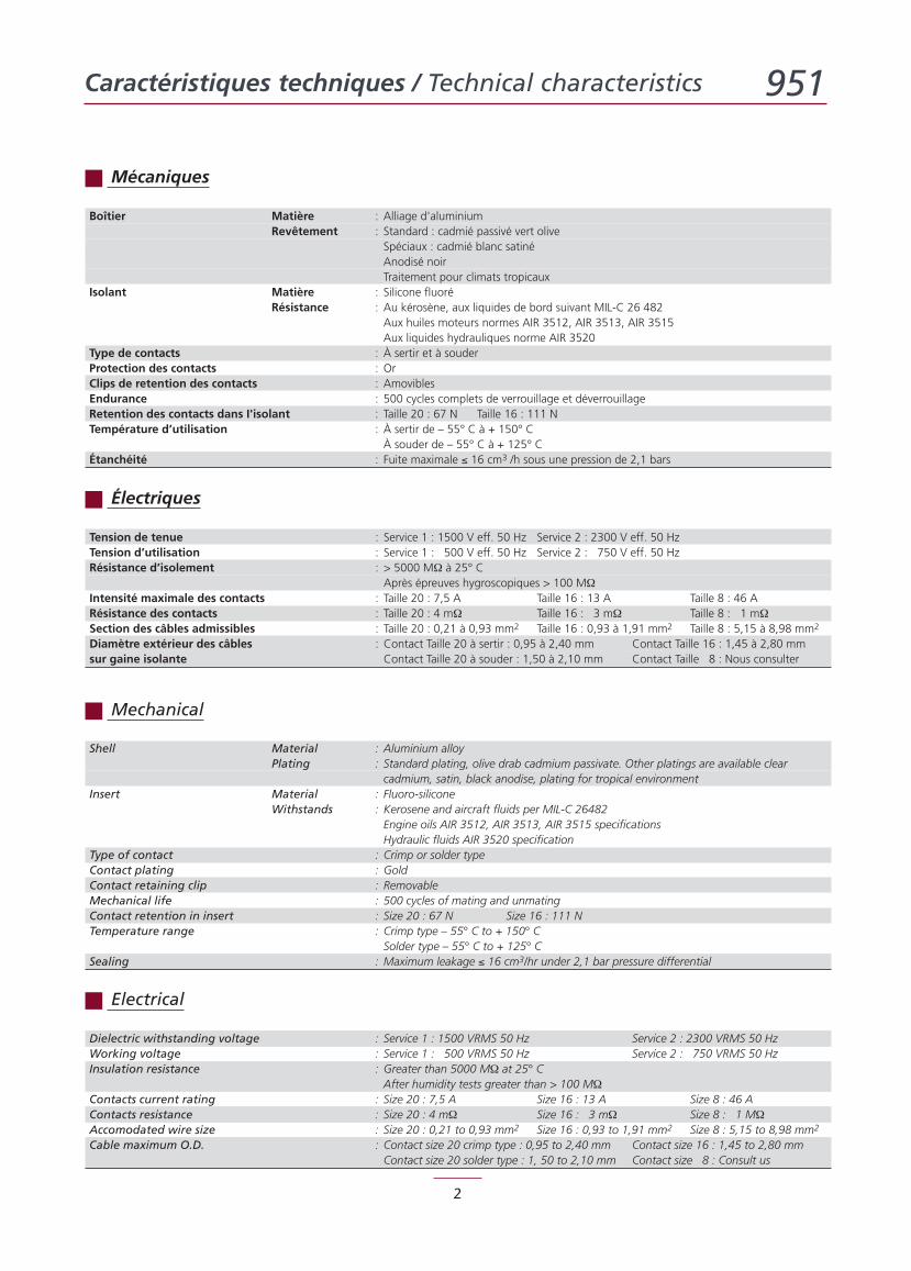
Boîtier Matière : Alliage d'aluminiumRevêtement : Standard : cadmié passivé vert olive
Spéciaux : cadmié blanc satinéAnodisé noirTraitement pour climats tropicaux
Isolant Matière : Silicone fluoréRésistance : Au kérosène, aux liquides de bord suivant MIL-C 26 482
Aux huiles moteurs normes AIR 3512, AIR 3513, AIR 3515Aux liquides hydrauliques norme AIR 3520
Type de contacts : À sertir et à souderProtection des contacts : OrClips de retention des contacts : AmoviblesEndurance : 500 cycles complets de verrouillage et déverrouillageRetention des contacts dans I'isolant : Taille 20 : 67 N Taille 16 : 111 NTempérature d’utilisation : À sertir de – 55° C à + 150° C
À souder de – 55° C à + 125° CÉtanchéité : Fuite maximale ≤ 16 cm3 /h sous une pression de 2,1 bars
Shell Material : Aluminium alloyPlating : Standard plating, olive drab cadmium passivate. Other platings are available clear
cadmium, satin, black anodise, plating for tropical environmentInsert Material : Fluoro-silicone
Withstands : Kerosene and aircraft fluids per MIL-C 26482Engine oils AIR 3512, AIR 3513, AIR 3515 specificationsHydraulic fluids AIR 3520 specification
Type of contact : Crimp or solder typeContact plating : GoldContact retaining clip : RemovableMechanical life : 500 cycles of mating and unmatingContact retention in insert : Size 20 : 67 N Size 16 : 111 NTemperature range : Crimp type – 55° C to + 150° C
Solder type – 55° C to + 125° CSealing : Maximum leakage ≤ 16 cm3/hr under 2,1 bar pressure differential
Tension de tenue : Service 1 : 1500 V eff. 50 Hz Service 2 : 2300 V eff. 50 HzTension d’utilisation : Service 1 : 500 V eff. 50 Hz Service 2 : 750 V eff. 50 HzRésistance d’isolement : > 5000 MΩ à 25° C
Après épreuves hygroscopiques > 100 MΩIntensité maximale des contacts : Taille 20 : 7,5 A Taille 16 : 13 A Taille 8 : 46 ARésistance des contacts : Taille 20 : 4 mΩ Taille 16 : 3 mΩ Taille 8 : 1 mΩSection des câbles admissibles : Taille 20 : 0,21 à 0,93 mm2 Taille 16 : 0,93 à 1,91 mm2 Taille 8 : 5,15 à 8,98 mm2
Diamètre extérieur des câbles : Contact Taille 20 à sertir : 0,95 à 2,40 mm Contact Taille 16 : 1,45 à 2,80 mmsur gaine isolante Contact Taille 20 à souder : 1,50 à 2,10 mm Contact Taille 8 : Nous consulter
Dielectric withstanding voltage : Service 1 : 1500 VRMS 50 Hz Service 2 : 2300 VRMS 50 HzWorking voltage : Service 1 : 500 VRMS 50 Hz Service 2 : 750 VRMS 50 HzInsulation resistance : Greater than 5000 MΩ at 25° C
After humidity tests greater than > 100 MΩContacts current rating : Size 20 : 7,5 A Size 16 : 13 A Size 8 : 46 AContacts resistance : Size 20 : 4 mΩ Size 16 : 3 mΩ Size 8 : 1 MΩAccomodated wire size : Size 20 : 0,21 to 0,93 mm2 Size 16 : 0,93 to 1,91 mm2 Size 8 : 5,15 to 8,98 mm2
Cable maximum O.D. : Contact size 20 crimp type : 0,95 to 2,40 mm Contact size 16 : 1,45 to 2,80 mmContact size 20 solder type : 1, 50 to 2,10 mm Contact size 8 : Consult us
Mécaniques
Électriques
Mechanical
Electrical
Système de référence / Part-numbering system 951
3
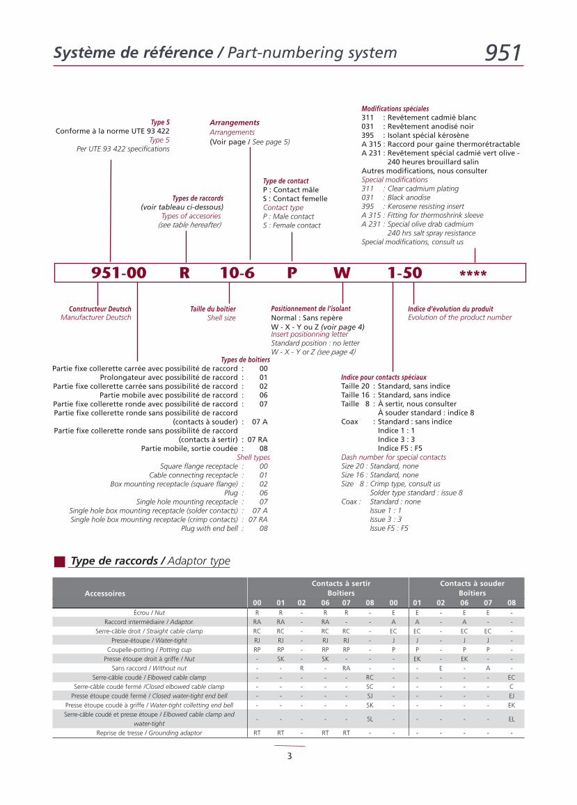
Constructeur DeutschManufacturer Deutsch
Type 5Conforme à la norme UTE 93 422
Type 5Per UTE 93 422 specifications
Types de boîtiersPartie fixe collerette carrée avec possibilité de raccord : 00
Prolongateur avec possibilité de raccord : 01Partie fixe collerette carrée sans possibilité de raccord : 02
Partie mobile avec possibilité de raccord : 06Partie fixe collerette ronde avec possibilité de raccord : 07Partie fixe collerette ronde sans possibilité de raccord
(contacts à souder) : 07 APartie fixe collerette ronde sans possibilité de raccord
(contacts à sertir) : 07 RAPartie mobile, sortie coudée : 08
Shell typesSquare flange receptacle : 00
Cable connecting receptacle : 01Box mounting receptacle (square flange) : 02
Plug : 06Single hole mounting receptacle : 07
Single hole box mounting receptacle (solder contacts) : 07 ASingle hole box mounting receptacle (crimp contacts) : 07 RA
Plug with end bell : 08
Taille du boîtierShell size
ArrangementsArrangements(Voir page / See page 5)
Types de raccords(voir tableau ci-dessous)
Types of accesories(see table hereafter)
Indice pour contacts spéciauxTaille 20 : Standard, sans indiceTaille 16 : Standard, sans indiceTaille 8 : À sertir, nous consulter
À souder standard : indice 8Coax : Standard : sans indice
Indice 1 : 1Indice 3 : 3Indice F5 : F5
Dash number for special contactsSize 20 : Standard, noneSize 16 : Standard, noneSize 8 : Crimp type, consult us
Solder type standard : issue 8Coax : Standard : none
Issue 1 : 1Issue 3 : 3Issue F5 : F5
Indice d’évolution du produitEvolution of the product number
Type de contactP : Contact mâleS : Contact femelleContact typeP : Male contactS : Female contact
Modifications spéciales311 : Revêtement cadmié blanc031 : Revêtement anodisé noir395 : Isolant spécial kérosèneA 315 : Raccord pour gaine thermorétractableA 231 : Revêtement spécial cadmié vert olive -
240 heures brouillard salinAutres modifications, nous consulterSpecial modifications311 : Clear cadmium plating031 : Black anodise395 : Kerosene resisting insertA 315 : Fitting for thermoshrink sleeveA 231 : Special olive drab cadmium
240 hrs salt spray resistanceSpecial modifications, consult us
Positionnement de l’isolantNormal : Sans repèreW - X - Y ou Z (voir page 4)Insert positionning letterStandard position : no letterW - X - Y or Z (see page 4)
951-00 R 10-6 P W 1-50 ****
Contacts à sertir Contacts à souderBoîtiers BoîtiersAccessoires
00 01 02 06 07 08 00 01 02 06 07 08Écrou / Nut R R - R R - E E - E E -
Raccord intermédiaire / Adaptor. RA RA - RA - - A A - A - -
Serre-câble droit / Straight cable clamp RC RC - RC RC - EC EC - EC EC -
Presse-étoupe / Water-tight RJ RJ - RJ RJ - J J - J J -
Coupelle-potting / Potting cup RP RP - RP RP - P P - P P -
Presse étoupe droit à griffe / Nut - SK - SK - - - EK - EK - -
Sans raccord / Without nut - - R - RA - - - E - A -
Serre-câble coudé / Elbowed cable clamp - - - - - RC - - - - - EC
Serre-câble coudé fermé /Closed elbowed cable clamp - - - - - SC - - - - - C
Presse étoupe coudé fermé / Closed water-tight end bell - - - - - SJ - - - - - EJ
Presse étoupe coudé à griffe / Water-tight colletting end bell - - - - - SK - - - - - EK
Serre-câble coudé et presse étoupe / Elbowed cable clamp and
water-tight- - - - - SL - - - - - EL
Reprise de tresse / Grounding adaptor RT RT - RT RT - - - - - - -
Type de raccords / Adaptor type
Positionnement angulaire / Key orientation 951
4
H B
G K J C
F D
A
E
H
B
GK
JC
F
D
A
E
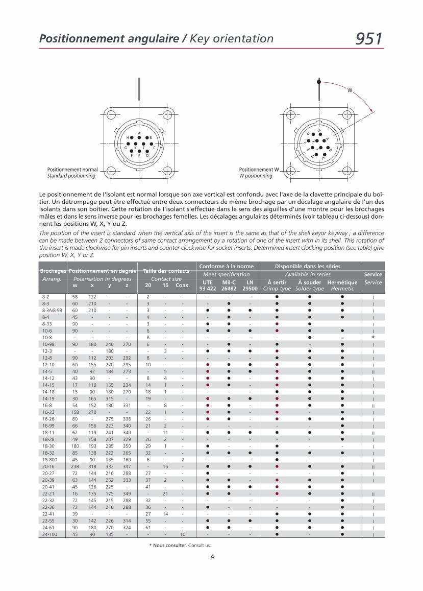
Positionnement WW positionning
Positionnement normalStandard positionning
W
Conforme à la norme Disponible dans les sériesBrochages Positionnement en degrés Taille des contacts
Meet specification Available in series ServiceArrang. Polarisation in degrees Contact size
UTE Mil-C LN À sertir À souder Hermétique Servicew x y z 20 16 Coax.93 422 26482 29500 Crimp type Solder type Hermetic
8-2 58 122 - - 2 - - - - - • • • I8-3 60 210 - - 3 - - - • - • • • I8-3A/8-98 60 210 - - 3 - - • • • • • • I8-4 45 - - - 4 - - - • - • • • I8-33 90 - - - 3 - - • • - • • I10-6 90 - - - 6 - - • • • • • • I10-8 - - - - 8 - - - - - - • - *10-98 90 180 240 270 6 - - - • - • - • I12-3 - - 180 - - 3 - • • • • • • I12-8 90 112 203 292 8 - - - - - • • • I12-10 60 155 270 295 10 - - • • • • • • I14-5 40 92 184 273 - 5 - • • • • • • II14-12 43 90 - - 8 4 - • • - • • • I14-15 17 110 155 234 14 1 - • • - • • • I14-18 15 90 180 270 18 1 - - - - • • • I14-19 30 165 315 - 19 - - • • • • • • I16-8 54 152 180 331 - 8 - • • - • • • II16-23 158 270 - - 22 1 - • • - • - • I16-26 60 - 275 338 26 - - • • - • • • I16-99 66 156 223 340 21 2 - - - - - - • I18-11 62 119 241 340 - 11 - • • • • • • II18-28 49 158 207 329 26 2 - - - - - - • I18-30 180 193 285 350 29 1 - • - - • - - I18-32 85 138 222 265 32 - - • • • • • • I18-800 45 90 135 160 6 - 2 - - - • - - I20-16 238 318 333 347 - 16 - • • • • • • II20-27 72 144 216 288 27 - - • - - - - • I20-39 63 144 252 333 37 2 - • • - • • • I20-41 45 126 225 - 41 - - • • • • • •22-21 16 135 175 349 - 21 - • • - • • • II22-32 72 145 215 288 32 - - - - - - - • I22-36 72 144 216 288 36 - - • - - - - • I22-41 39 - - - 27 14 - - - - • • • I22-55 30 142 226 314 55 - - • • • • • • I24-61 90 180 270 324 61 - - • • - • • • I24-100 45 90 135 - - - 10 - - - • - • I
Le positionnement de I'isolant est normal lorsque son axe vertical est confondu avec l'axe de la clavette principale du boî-tier. Un détrompage peut être effectué entre deux connecteurs de même brochage par un décalage angulaire de I'un desisolants dans son boîtier. Cette rotation de I'isolant s'effectue dans le sens des aiguilles d'une montre pour les brochagesmâles et dans le sens inverse pour les brochages femelles. Les décalages angulaires déterminés (voir tableau ci-dessous) don-nent les positions W, X, Y ou Z.
The position of the insert is standard when the vertical axis of the insert is the same as that of the shell keyor keyway ; a differencecan be made between 2 connectors of same contact arrangement by a rotation of one of the insert with in its shell. This rotation ofthe insert is made clockwise for pin inserts and counter-clockwise for socket inserts. Determined insert clocking position (see table) giveposition W, X, Y or Z.
* Nous consulter. Consult us.
5
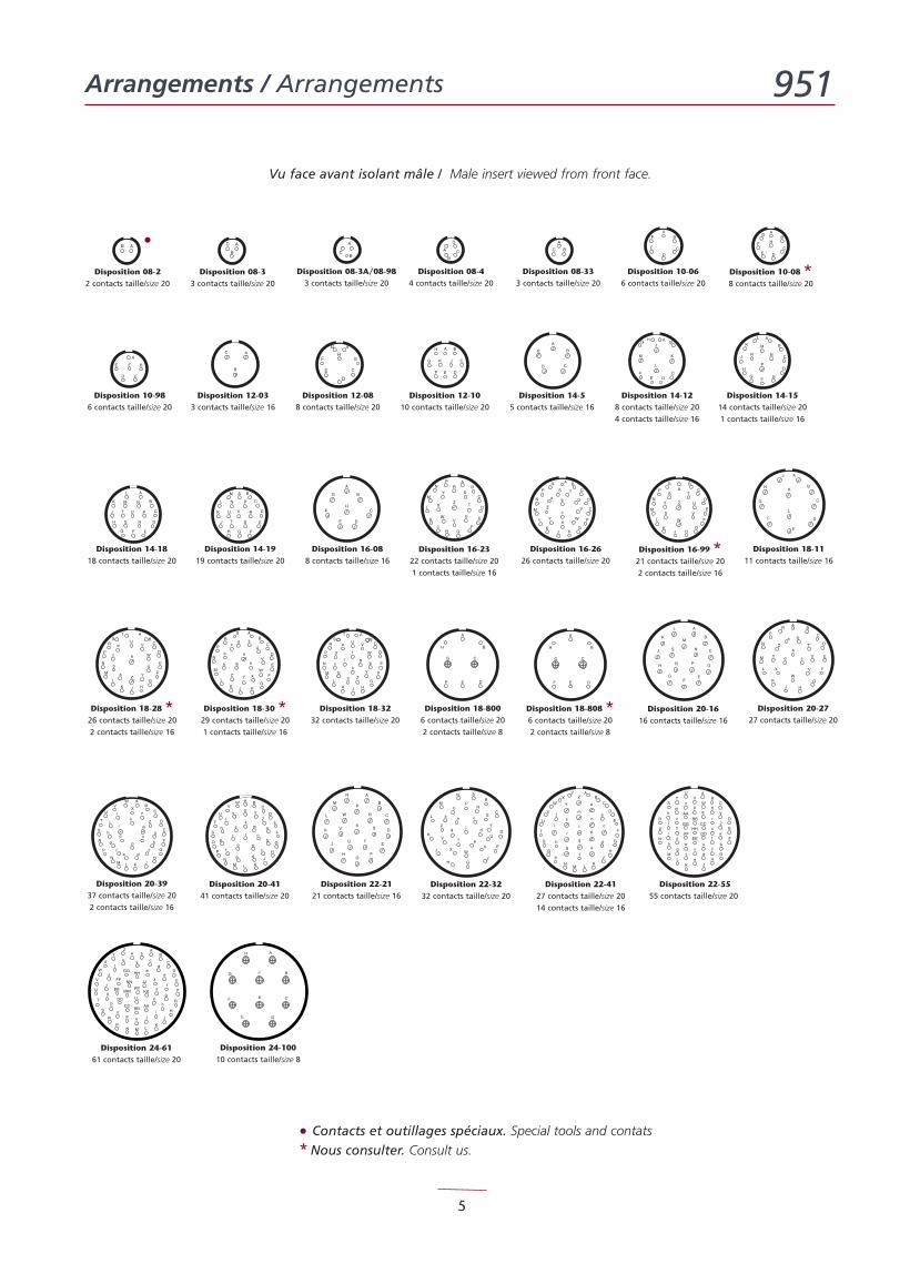
Arrangements / Arrangements 951
A
B
C
F
E
GH
J
K
N
M
D
L
P
R
S
TU
V
W
Xj
m
W
X
e
i
g
A
C
D
E
F
G
HJKLM
N
P
R
hS
T
p
q
r
f
B
dc
k
V
b
U
Z
n
Y
a
HJK
C
D
M
L
N
R
P
G
S T
U
V
WX
Y
Z
a b
c
CD
A
BE
CD
E F
A
B
H
G JK
Disposition 12-1010 contacts taille/size 20
Disposition 14-55 contacts taille/size 16
Disposition 20-3937 contacts taille/size 20
2 contacts taille/size 16
Disposition 22-2121 contacts taille/size 16
F
E
G
H
J
KN M L
P
R
S
T
U
V
W
X
Za
c
d
e
f
g
h
i-j-m
n
p_
q_
r
s
t
AABB
CC
DD
EE
FF
GG HH
u v
w
x
y
z
Y b
JJ
KK
LL
MM
NN
PP
AB
C
D
k
Disposition 24-6161 contacts taille/size 20
A
B
CF
E
G
H
J
K
D
Disposition 24-10010 contacts taille/size 8
A
B
C
D
E
L
F
G
H
J
K
AB
C
D
E
F
G
HJK
L
M
N
P
RS
T
UV
W
X
Y
Zab
c
d
e
f
g
h
l
AB
C
D
E
F
G
HJK
L
M
N
P
RS
T
UV
W
X
YZ
a
b
c
d
e
A
B
C
DEF
G
H
HC
D
G
HJ
K
C
D
M
L
N RP
G
S
T
UV
W
X
Y
Z
HJK
C
D
M
L
N
R
P
G
S T
U
V
W
X
Y Z
AB
C
F
E
G
H
J
KNM
D
P
R
S
T
U
V
WX
YZ
a
b
c
de
f
gh
i-
j-
k
m
n
p_
q_
r
s
t
L
AB
C
D
E
FGH
J
K
L
M
N
PR
S
T
U
VW
X
Y
Z
a
b
c
d
ef
g
h
j
t
m
p
n
q
h
jk
BC
D
E
F
G
H
JKLM
N
P
R
S
T
U
VW
r
sk
A
YX
Z
b
a
c
de
f
g
AB
C
F
E
GH
JK
N
M
D
L
P
R
ST
UV
WX
Y
Z
a
bc
de
fg
h
i-
j-
km
np_
q_r
s
t
AABB
CC
DDEE
FF
GGHH
uv
wx
y
z
Disposition 22-4127 contacts taille/size 20
14 contacts taille/size 16
Disposition 10-066 contacts taille/size 20
Disposition 14-128 contacts taille/size 20
4 contacts taille/size 16
Disposition 16-99 *21 contacts taille/size 20
2 contacts taille/size 16
Disposition 18-1111 contacts taille/size 16
Disposition 20-4141 contacts taille/size 20
Disposition 22-5555 contacts taille/size 20
D
E
F
G
H
Disposition 08-3A/08-983 contacts taille/size 20
Disposition 12-088 contacts taille/size 20
Disposition 10-986 contacts taille/size 20
Disposition 08-44 contacts taille/size 20
A
B
C
D
Disposition 08-333 contacts taille/size 20
C
DE
F
G
H
AB
HGJ
K
CDE
M
L
F
BA
H
G
J
K
C
D
M
L
NR
P
FE
H
J
K
C
D
M
L
N
R
P
G
S
T U
H
J
K
C
D
M
L N
R
P
G
ST
U V
Disposition 16-2626 contacts taille/size 20
AB
C
D
E
F
GHJK
L
M
N
P
RS
T
U
V
WXYZ
a
b
cd
e
g h
A
B
C
DEF
G
H
Disposition 08-22 contacts taille/size 20
Disposition 08-33 contacts taille/size 20
Disposition 10-08 *8 contacts taille/size 20
Disposition 12-033 contacts taille/size 16
Disposition 14-1514 contacts taille/size 20
1 contacts taille/size 16
Disposition 14-1818 contacts taille/size 20
Disposition 14-1919 contacts taille/size 20
Disposition 16-088 contacts taille/size 16
Disposition 16-2322 contacts taille/size 20
1 contacts taille/size 16
Disposition 18-28 *26 contacts taille/size 20
2 contacts taille/size 16
Disposition 18-30 *29 contacts taille/size 20
1 contacts taille/size 16
Disposition 18-3232 contacts taille/size 20
Disposition 18-8006 contacts taille/size 20
2 contacts taille/size 8
Disposition 18-808 *6 contacts taille/size 20
2 contacts taille/size 8
A
B
C
D
EF
G
H
J
K
L
M
N
PR
S
Disposition 20-2727 contacts taille/size 20
AB
C
D
E
bT
U
V
W
X
Y
Z
a
K
L
M
N
P
F
G
HJ
R
S
cd
Disposition 20-1616 contacts taille/size 16
Disposition 22-3232 contacts taille/size 20
•
• Contacts et outillages spéciaux. Special tools and contats
* Nous consulter. Consult us.
Vu face avant isolant mâle / Male insert viewed from front face.
Embases / Receptacles 951
6
A
B
B A
4 trous/holes Ø 3,15 ± 0,15 Tailles/sizes 08 à/to 224 trous/holes Ø 3,73 ± 0,15 Taille/size 24
GC
D E
F
A
B
B A
4 trous/holes Ø 3,15 ± 0,15 Tailles/sizes 08 à/to 224 trous/holes Ø 3,73 ± 0,15 Taille/size 24
Ø câble acceptéØ allowed cable
GJC
D E
F
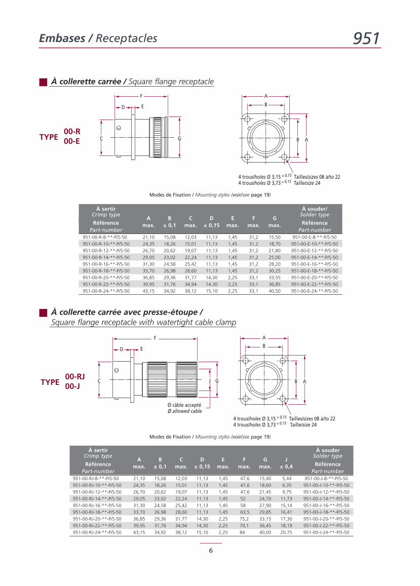
À collerette carrée / Square flange receptacle
À collerette carrée avec presse-étoupe /Square flange receptacle with watertight cable clamp
00-RTYPE 00-E
00-RJTYPE 00-J
Modes de Fixation / Mounting styles (voir/see page 19)
Modes de Fixation / Mounting styles (voir/see page 19)
À sertir À souder/Crimp type Solder type
RéférenceA B C D E F G
RéférencePart-number
max. ± 0,1 max. ± 0,15 max. max. max.Part-number
951-00-R-8-**-P/S-50 21,10 15,08 12,03 11,13 1,45 31,2 15,50 951-00-E-8-**-P/S-50
951-00-R-10-**-P/S-50 24,35 18,26 15,01 11,13 1,45 31,2 18,70 951-00-E-10-**-P/S-50
951-00-R-12-**-P/S-50 26,70 20,62 19,07 11,13 1,45 31,2 21,80 951-00-E-12-**-P/S-50
951-00-R-14-**-P/S-50 29,05 23,02 22,24 11,13 1,45 31,2 25,00 951-00-E-14-**-P/S-50
951-00-R-16-**-P/S-50 31,30 24,58 25,42 11,13 1,45 31,2 28,20 951-00-E-16-**-P/S-50
951-00-R-18-**-P/S-50 33,70 26,98 28,60 11,13 1,45 31,2 30,25 951-00-E-18-**-P/S-50
951-00-R-20-**-P/S-50 36,85 29,36 31,77 14,30 2,25 33,1 33,55 951-00-E-20-**-P/S-50
951-00-R-22-**-P/S-50 39,95 31,76 34,94 14,30 2,25 33,1 36,85 951-00-E-22-**-P/S-50
951-00-R-24-**-P/S-50 43,15 34,92 38,12 15,10 2,25 33,1 40,50 951-00-E-24-**-P/S-50
À sertir À souderCrimp type Solder type
RéférenceA B C D E F G J
RéférencePart-number
max. ± 0,1 max. ± 0,15 max. max. max. ± 0,4Part-number
951-00-RJ-8-**-P/S-50 21,10 15,08 12,03 11,13 1,45 47,6 15,40 5,44 951-00-J-8-**-P/S-50
951-00-RJ-10-**-P/S-50 24,35 18,26 15,01 11,13 1,45 47,6 18,60 6,35 951-00-J-10-**-P/S-50
951-00-RJ-12-**-P/S-50 26,70 20,62 19,07 11,13 1,45 47,6 21,45 9,75 951-00-J-12-**-P/S-50
951-00-RJ-14-**-P/S-50 29,05 23,02 22,24 11,13 1,45 52,0 24,70 11,73 951-00-J-14-**-P/S-50
951-00-RJ-16-**-P/S-50 31,30 24,58 25,42 11,13 1,45 58,0 27,90 15,14 951-00-J-16-**-P/S-50
951-00-RJ-18-**-P/S-50 33,70 26,98 28,60 11,13 1,45 63,5 29,85 16,41 951-00-J-18-**-P/S-50
951-00-RJ-20-**-P/S-50 36,85 29,36 31,77 14,30 2,25 75,2 33,15 17,30 951-00-J-20-**-P/S-50
951-00-RJ-22-**-P/S-50 39,95 31,76 34,94 14,30 2,25 79,1 36,45 18,19 951-00-J-22-**-P/S-50
951-00-RJ-24-**-P/S-50 43,15 34,92 38,12 15,10 2,25 84,0 40,00 20,75 951-00-J-24-**-P/S-50
Embases / Receptacles 951
7
A
B
B A
4 trous/holes Ø 3,15 ± 0,15 Tailles/sizes 08 à/to 224 trous/holes Ø 3,73 ± 0,15 Taille/size 24
GJC
D E
F
GC
D E D
F1
E
F A
B
B A CG1
4 trous/holes Ø 3,15 ± 0,15 Tailles/sizes 08 à/to 224 trous/holes Ø 3,73 ± 0,15 Taille/size 24
5,70 max.
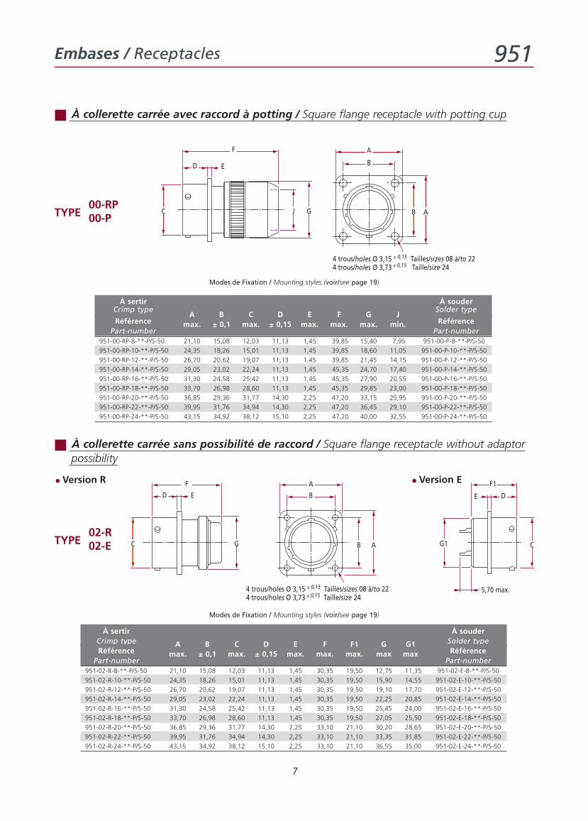
À collerette carrée avec raccord à potting / Square flange receptacle with potting cup
00-RPTYPE 00-P
Modes de Fixation / Mounting styles (voir/see page 19)
À collerette carrée sans possibilité de raccord / Square flange receptacle without adaptorpossibility
02-RTYPE 02-E
• Version R • Version E
À sertir À souderCrimp type Solder typeRéférence
A B C D E F F1 G G1Référence
Part-numbermax. ± 0,1 max. ± 0,15 max. max. max. max max
Part-number951-02-R-8-**-P/S-50 21,10 15,08 12,03 11,13 1,45 30,35 19,50 12,75 11,35 951-02-E-8-**-P/S-50
951-02-R-10-**-P/S-50 24,35 18,26 15,01 11,13 1,45 30,35 19,50 15,90 14,55 951-02-E-10-**-P/S-50
951-02-R-12-**-P/S-50 26,70 20,62 19,07 11,13 1,45 30,35 19,50 19,10 17,70 951-02-E-12-**-P/S-50
951-02-R-14-**-P/S-50 29,05 23,02 22,24 11,13 1,45 30,35 19,50 22,25 20,85 951-02-E-14-**-P/S-50
951-02-R-16-**-P/S-50 31,30 24,58 25,42 11,13 1,45 30,35 19,50 25,45 24,00 951-02-E-16-**-P/S-50
951-02-R-18-**-P/S-50 33,70 26,98 28,60 11,13 1,45 30,35 19,50 27,05 25,50 951-02-E-18-**-P/S-50
951-02-R-20-**-P/S-50 36,85 29,36 31,77 14,30 2,25 33,10 21,10 30,20 28,65 951-02-E-20-**-P/S-50
951-02-R-22-**-P/S-50 39,95 31,76 34,94 14,30 2,25 33,10 21,10 33,35 31,85 951-02-E-22-**-P/S-50
951-02-R-24-**-P/S-50 43,15 34,92 38,12 15,10 2,25 33,10 21,10 36,55 35,00 951-02-E-24-**-P/S-50
À sertir À souderCrimp type Solder type
RéférenceA B C D E F G J
RéférencePart-number
max. ± 0,1 max. ± 0,15 max. max. max. min.Part-number
951-00-RP-8-**-P/S-50 21,10 15,08 12,03 11,13 1,45 39,85 15,40 7,95 951-00-P-8-**-P/S-50
951-00-RP-10-**-P/S-50 24,35 18,26 15,01 11,13 1,45 39,85 18,60 11,05 951-00-P-10-**-P/S-50
951-00-RP-12-**-P/S-50 26,70 20,62 19,07 11,13 1,45 39,85 21,45 14,15 951-00-P-12-**-P/S-50
951-00-RP-14-**-P/S-50 29,05 23,02 22,24 11,13 1,45 45,35,0 24,70 17,40 951-00-P-14-**-P/S-50
951-00-RP-16-**-P/S-50 31,30 24,58 25,42 11,13 1,45 45,350 27,90 20,55 951-00-P-16-**-P/S-50
951-00-RP-18-**-P/S-50 33,70 26,98 28,60 11,13 1,45 45,35 29,85 23,00 951-00-P-18-**-P/S-50
951-00-RP-20-**-P/S-50 36,85 29,36 31,77 14,30 2,25 47,20 33,15 25,95 951-00-P-20-**-P/S-50
951-00-RP-22-**-P/S-50 39,95 31,76 34,94 14,30 2,25 47,20 36,45 29,10 951-00-P-22-**-P/S-50
951-00-RP-24-**-P/S-50 43,15 34,92 38,12 15,10 2,25 47,20,0 40,00 32,55 951-00-P-24-**-P/S-50
Modes de Fixation / Mounting styles (voir/see page 19)
Embases / Receptacles 951
8
C GJ
D E
F
Ø max. brides serréesØ tightened clamps
Ø max. câble acceptéØ allowed cable
A
J1
B
A
B
C H GJ
D EF
Ø max. câble acceptéØ allowed cable
3,30 min.
M
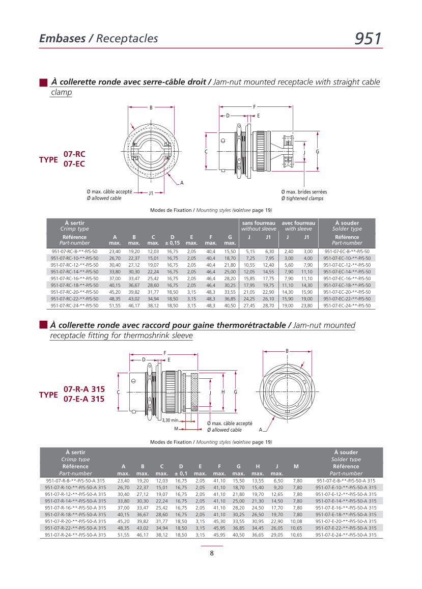
À collerette ronde avec serre-câble droit / Jam-nut mounted receptacle with straight cableclamp
07-RCTYPE 07-EC
Modes de Fixation / Mounting styles (voir/see page 19)
À collerette ronde avec raccord pour gaine thermorétractable / Jam-nut mountedreceptacle fitting for thermoshrink sleeve
07-R-A 315TYPE 07-E-A 315
Modes de Fixation / Mounting styles (voir/see page 19)
À sertir À souderCrimp type Solder typeRéférence A B C D E F G H J M Référence
Part-number max. max. max. ± 0,1 max. max. max. max. max. Part-number951-07-R-8-**-P/S-50-A 315 23,40 19,20 12,03 16,75 2,05 41,10 15,50 13,55 6,50 7,80 951-07-E-8-**-P/S-50-A 315
951-07-R-10-**-P/S-50-A 315 26,70 22,37 15,01 16,75 2,05 41,10 18,70 15,40 9,20 7,80 951-07-E-10-**-P/S-50-A 315
951-07-R-12-**-P/S-50-A 315 30,40 27,12 19,07 16,75 2,05 41,10 21,80 19,70 12,65 7,80 951-07-E-12-**-P/S-50-A 315
951-07-R-14-**-P/S-50-A 315 33,80 30,30 22,24 16,75 2,05 41,10 25,00 21,30 14,50 7,80 951-07-E-14-**-P/S-50-A 315
951-07-R-16-**-P/S-50-A 315 37,00 33,47 25,42 16,75 2,05 41,10 28,20 24,50 17,70 7,80 951-07-E-16-**-P/S-50-A 315
951-07-R-18-**-P/S-50-A 315 40,15 36,67 28,60 16,75 2,05 41,10 30,25 26,50 19,70 7,80 951-07-E-18-**-P/S-50-A 315
951-07-R-20-**-P/S-50-A 315 45,20 39,82 31,77 18,50 3,15 45,30 33,55 30,95 22,90 10,08 951-07-E-20-**-P/S-50-A 315
951-07-R-22-**-P/S-50-A 315 48,35 43,02 34,94 18,50 3,15 45,95 36,85 34,45 26,05 10,65 951-07-E-22-**-P/S-50-A 315
951-07-R-24-**-P/S-50-A 315 51,55 46,17 38,12 18,50 3,15 45,95 40,50 36,65 29,05 10,65 951-07-E-24-**-P/S-50-A 315
À sertir sans fourreau avec fourreau À souderCrimp type without sleeve with sleeve Solder type
Référence A B C D E F G J J1 J J1 RéférencePart-number max. max. max. ± 0,15 max. max. max. Part-number
951-07-RC-8-**-P/S-50 23,40 19,20 12,03 16,75 2,05 40,4 15,50 5,15 6,30 2,40 3,00 951-07-EC-8-**-P/S-50
951-07-RC-10-**-P/S-50 26,70 22,37 15,01 16,75 2,05 40,4 18,70 7,25 7,95 3,00 4,00 951-07-EC-10-**-P/S-50
951-07-RC-12-**-P/S-50 30,40 27,12 19,07 16,75 2,05 40,4 21,80 10,55 12,40 5,60 7,90 951-07-EC-12-**-P/S-50
951-07-RC-14-**-P/S-50 33,80 30,30 22,24 16,75 2,05 46,4 25,00 12,05 14,55 7,90 11,10 951-07-EC-14-**-P/S-50
951-07-RC-16-**-P/S-50 37,00 33,47 25,42 16,75 2,05 46,4 28,20 15,85 17,75 7,90 11,10 951-07-EC-16-**-P/S-50
951-07-RC-18-**-P/S-50 40,15 36,67 28,60 16,75 2,05 46,4 30,25 17,95 19,75 11,10 14,30 951-07-EC-18-**-P/S-50
951-07-RC-20-**-P/S-50 45,20 39,82 31,77 18,50 3,15 48,3 33,55 21,05 22,90 14,30 15,90 951-07-EC-20-**-P/S-50
951-07-RC-22-**-P/S-50 48,35 43,02 34,94 18,50 3,15 48,3 36,85 24,25 26,10 15,90 19,00 951-07-EC-22-**-P/S-50
951-07-RC-24-**-P/S-50 51,55 46,17 38,12 18,50 3,15 48,3 40,50 27,45 28,70 19,00 23,80 951-07-EC-24-**-P/S-50
Embases / Receptacles 951
9
A
B
C CG
D E
F
4,05 max. Boitiers 8 à/to 18
Pas de dépassement tailles 8 à 24Contacts do not protude sizes 8 to 24
E
G1
D
F1
C J
D E
F
G
Ø max. câble acceptéØ allowed cable A
B
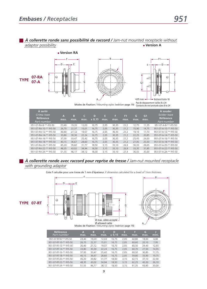
07-RATYPE 07-A
Modes de Fixation / Mounting styles (voir/see page 19)
À sertir À souderCrimp type Solder typeRéférence
A B C D E F F1 G G1Référence
Part-numbermax. max. max. ± 0,15 max. max. max. max. max.
Part-number951-07-RA-8-**-P/S-50 23,40 19,20 12,03 16,75 2,05 30,35 21,2 12,75 11,35 951-07-A-8-**-P/S-50
951-07-RA-10-**-P/S-50 26,70 22,37 15,01 16,75 2,05 30,35 21,2 15,90 14,75 951-07-A-10-**-P/S-50
951-07-RA-12-**-P/S-50 30,40 27,12 19,07 16,75 2,05 30,35 21,2 19,10 17,70 951-07-A-12-**-P/S-50
951-07-RA-14-**-P/S-50 33,80 30,30 22,24 16,75 2,05 30,35 21,2 22,25 20,85 951-07-A-14-**-P/S-50
951-07-RA-16-**-P/S-50 37,00 33,47 25,42 16,75 2,05 30,35 21,2 25,45 24,00 951-07-A-16-**-P/S-50
951-07-RA-18-**-P/S-50 40,15 36,67 28,60 16,75 2,05 30,35 21,2 27,05 25,50 951-07-A-18-**-P/S-50
951-07-RA-20-**-P/S-50 45,20 39,82 31,77 18,50 3,15 33,10 26,9 30,20 28,65 951-07-A-20-**-P/S-50
951-07-RA-22-**-P/S-50 48,35 43,02 34,94 18,50 3,15 33,10 26,9 33,35 31,85 951-07-A-22-**-P/S-50
951-07-RA-24-**-P/S-50 51,55 46,17 38,12 18,50 3,15 33,10 27,4 36,55 35,00 951-07-A-24-**-P/S-50
• Version RA
• Version A
À collerette ronde avec raccord pour reprise de tresse / Jam-nut mounted receptaclewith grounding adaptor
TYPE 07-RT
Modes de Fixation / Mounting styles (voir/see page 19)
Référence A B C D E F G JPart-number max. max. max. ± 0,15 max. max. max. mini.
951-07-RT-8-**-P/S-50 23,40 19,20 12,03 16,75 2,05 60,80 18,00 6,80
951-07-RT-10-**-P/S-50 26,70 22,37 15,01 16,75 2,05 60,60 20,10 7,95
951-07-RT-12-**-P/S-50 30,40 27,12 19,07 16,75 2,05 60,50 24,40 12,65
951-07-RT-14-**-P/S-50 33,80 30,30 22,24 16,75 2,05 60,70 27,50 14,55
951-07-RT-16-**-P/S-50 37,00 33,47 25,42 16,75 2,05 60,50 30,85 17,75
951-07-RT-18-**-P/S-50 40,15 36,67 28,60 16,75 2,05 59,80 33,90 19,75
951-07-RT-20-**-P/S-50 45,20 39,82 31,77 18,50 3,15 62,15 37,10 22,90
951-07-RT-22-**-P/S-50 48,35 43,02 34,94 18,50 3,15 62,25 40,20 26,10
951-07-RT-24-**-P/S-50 51,55 46,17 38,12 18,50 3,15 61,35 43,40 30,00
À collerette ronde sans possibilité de raccord / Jam-nut mounted receptacle withoutadaptor possibility
Cote F calculée pour une tresse de 1 mm d’épaisseur. F dimension calculated for a braid of 1mm thickness
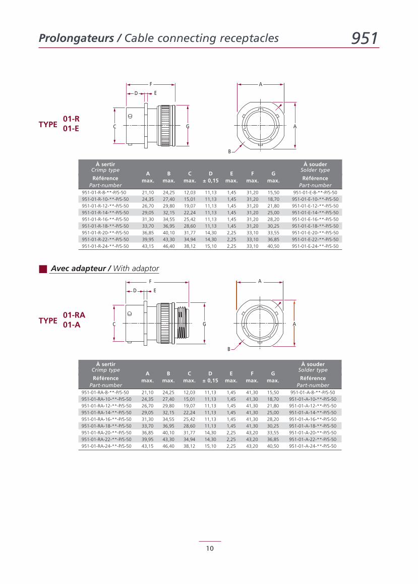
Prolongateurs / Cable connecting receptacles 951
10
G AC
D E
F A
B
G AC
ED
F A
B
Avec adapteur / With adaptor
01-RTYPE 01-E
01-RATYPE 01-A
À sertir À souderCrimp type Solder type
RéférenceA B C D E F G
RéférencePart-number
max. max. max. ± 0,15 max. max. max.Part-number
951-01-R-8-**-P/S-50 21,10 24,25 12,03 11,13 1,45 31,20 15,50 951-01-E-8-**-P/S-50
951-01-R-10-**-P/S-50 24,35 27,40 15,01 11,13 1,45 31,20 18,70 951-01-E-10-**-P/S-50
951-01-R-12-**-P/S-50 26,70 29,80 19,07 11,13 1,45 31,20 21,80 951-01-E-12-**-P/S-50
951-01-R-14-**-P/S-50 29,05 32,15 22,24 11,13 1,45 31,20 25,00 951-01-E-14-**-P/S-50
951-01-R-16-**-P/S-50 31,30 34,55 25,42 11,13 1,45 31,20 28,20 951-01-E-16-**-P/S-50
951-01-R-18-**-P/S-50 33,70 36,95 28,60 11,13 1,45 31,20 30,25 951-01-E-18-**-P/S-50
951-01-R-20-**-P/S-50 36,85 40,10 31,77 14,30 2,25 33,10 33,55 951-01-E-20-**-P/S-50
951-01-R-22-**-P/S-50 39,95 43,30 34,94 14,30 2,25 33,10 36,85 951-01-E-22-**-P/S-50
951-01-R-24-**-P/S-50 43,15 46,40 38,12 15,10 2,25 33,10 40,50 951-01-E-24-**-P/S-50
À sertir À souderCrimp type Solder type
RéférenceA B C D E F G
RéférencePart-number
max. max. max. ± 0,15 max. max. max.Part-number
951-01-RA-8-**-P/S-50 21,10 24,25 12,03 11,13 1,45 41,30 15,50 951-01-A-8-**-P/S-50
951-01-RA-10-**-P/S-50 24,35 27,40 15,01 11,13 1,45 41,30 18,70 951-01-A-10-**-P/S-50
951-01-RA-12-**-P/S-50 26,70 29,80 19,07 11,13 1,45 41,30 21,80 951-01-A-12-**-P/S-50
951-01-RA-14-**-P/S-50 29,05 32,15 22,24 11,13 1,45 41,30 25,00 951-01-A-14-**-P/S-50
951-01-RA-16-**-P/S-50 31,30 34,55 25,42 11,13 1,45 41,30 28,20 951-01-A-16-**-P/S-50
951-01-RA-18-**-P/S-50 33,70 36,95 28,60 11,13 1,45 41,30 30,25 951-01-A-18-**-P/S-50
951-01-RA-20-**-P/S-50 36,85 40,10 31,77 14,30 2,25 43,20 33,55 951-01-A-20-**-P/S-50
951-01-RA-22-**-P/S-50 39,95 43,30 34,94 14,30 2,25 43,20 36,85 951-01-A-22-**-P/S-50
951-01-RA-24-**-P/S-50 43,15 46,40 38,12 15,10 2,25 43,20 40,50 951-01-A-24-**-P/S-50
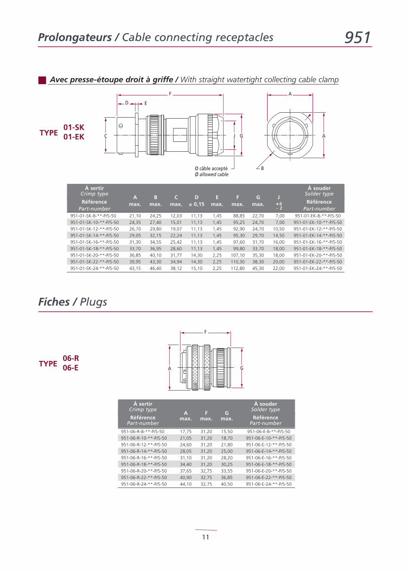
Prolongateurs / Cable connecting receptacles 951
11
J G A
A
B
C
D E
F
Ø câble acceptéØ allowed cable
GA
F
Avec presse-étoupe droit à griffe / With straight watertight collecting cable clamp
01-SKTYPE 01-EK
À sertir À souderCrimp type Solder type
RéférenceA B C D E F G J
RéférencePart-number
max. max. max. ± 0,15 max. max. max.Part-number
951-01-SK-8-**-P/S-50 21,10 24,25 12,03 11,13 1,45 88,85 22,70 7,00 951-01-EK-8-**-P/S-50
951-01-SK-10-**-P/S-50 24,35 27,40 15,01 11,13 1,45 95,25 24,70 7,00 951-01-EK-10-**-P/S-50
951-01-SK-12-**-P/S-50 26,70 29,80 19,07 11,13 1,45 92,90 24,70 10,50 951-01-EK-12-**-P/S-50
951-01-SK-14-**-P/S-50 29,05 32,15 22,24 11,13 1,45 95,30 29,70 14,50 951-01-EK-14-**-P/S-50
951-01-SK-16-**-P/S-50 31,30 34,55 25,42 11,13 1,45 97,60 31,70 16,00 951-01-EK-16-**-P/S-50
951-01-SK-18-**-P/S-50 33,70 36,95 28,60 11,13 1,45 99,80 33,70 18,00 951-01-EK-18-**-P/S-50
951-01-SK-20-**-P/S-50 36,85 40,10 31,77 14,30 2,25 107,10 35,30 18,00 951-01-EK-20-**-P/S-50
951-01-SK-22-**-P/S-50 39,95 43,30 34,94 14,30 2,25 110,30 38,30 20,00 951-01-EK-22-**-P/S-50
951-01-SK-24-**-P/S-50 43,15 46,40 38,12 15,10 2,25 112,80 45,30 22,00 951-01-EK-24-**-P/S-50
06-RTYPE 06-E
+0- 2
À sertir À souderCrimp type Solder type
RéférenceA F G
RéférencePart-number
max. max. max.Part-number
951-06-R-8-**-P/S-50 17,75 31,20 15,50 951-06-E-8-**-P/S-50
951-06-R-10-**-P/S-50 21,05 31,20 18,70 951-06-E-10-**-P/S-50
951-06-R-12-**-P/S-50 24,60 31,20 21,80 951-06-E-12-**-P/S-50
951-06-R-14-**-P/S-50 28,05 31,20 25,00 951-06-E-14-**-P/S-50
951-06-R-16-**-P/S-50 31,10 31,20 28,20 951-06-E-16-**-P/S-50
951-06-R-18-**-P/S-50 34,40 31,20 30,25 951-06-E-18-**-P/S-50
951-06-R-20-**-P/S-50 37,65 32,75 33,55 951-06-E-20-**-P/S-50
951-06-R-22-**-P/S-50 40,90 32,75 36,85 951-06-E-22-**-P/S-50
951-06-R-24-**-P/S-50 44,10 32,75 40,50 951-06-E-24-**-P/S-50
Fiches / Plugs
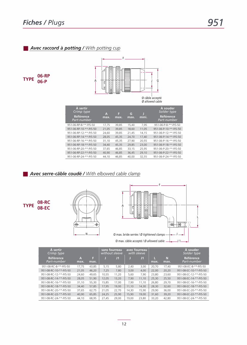
Fiches / Plugs 951
12
J GA
F
Ø câble acceptéØ allowed cable
F
A
L
Ø max. bride serrée / Ø tightened clamps
Ø max. câble accepté / Ø allowed cable J 1
JN
Avec raccord à potting / With potting cup
06-RPTYPE 06-P
Avec serre-câble coudé / With elbowed cable clamp
08-RCTYPE 08-EC
À sertir sans fourreau avec fourreau À souderCrimp type without sleeve with sleeve Solder type
Référence A F J J1 J J1 L N RéférencePart-number max. max. max. max. Part-number
951-08-RC-8-**-P/S-50 17,75 43,85 5,15 5,80 2,40 3,00 20,70 17,40 951-08-EC-8-**-P/S-50
951-08-RC-10-**-P/S-50 21,05 46,20 7,25 7,80 3,00 4,00 22,00 20,20 951-08-EC-10-**-P/S-50
951-08-RC-12-**-P/S-50 24,60 49,65 10,55 11,20 5,60 7,90 23,80 23,60 951-08-EC-12-**-P/S-50
951-08-RC-14-**-P/S-50 28,05 51,90 12,05 13,20 7,90 11,10 25,30 25,50 951-08-EC-14-**-P/S-50
951-08-RC-16-**-P/S-50 31,10 55,30 15,85 17,00 7,90 11,10 26,80 29,70 951-08-EC-16-**-P/S-50
951-08-RC-18-**-P/S-50 34,40 57,85 17,95 19,00 11,10 14,30 28,30 32,60 951-08-EC-18-**-P/S-50
951-08-RC-20-**-P/S-50 37,65 62,75 21,05 22,70 14,30 15,90 29,90 36,00 951-08-EC-20-**-P/S-50
951-08-RC-22-**-P/S-50 40,90 65,85 24,25 25,90 15,90 19,00 31,60 39,20 951-08-EC-22-**-P/S-50
951-08-RC-24-**-P/S-50 44,10 68,95 27,45 29,00 19,00 23,80 33,20 42,80 951-08-EC-24-**-P/S-50
À sertir À souderCrimp type Solder type
RéférenceA F G J
RéférencePart-number
max. max. max. mini.Part-number
951-06-RP-8-**-P/S-50 17,75 39,85 15,40 7,95 951-06-P-8-**-P/S-50
951-06-RP-10-**-P/S-50 21,05 39,85 18,60 11,05 951-06-P-10-**-P/S-50
951-06-RP-12-**-P/S-50 24,60 39,85 21,45 14,15 951-06-P-12-**-P/S-50
951-06-RP-14-**-P/S-50 28,05 45,35 24,70 17,40 951-06-P-14-**-P/S-50
951-06-RP-16-**-P/S-50 31,10 45,35 27,90 20,55 951-06-P-16-**-P/S-50
951-06-RP-18-**-P/S-50 34,40 45,35 29,85 23,00 951-06-P-18-**-P/S-50
951-06-RP-20-**-P/S-50 37,65 46,85 33,15 25,95 951-06-P-20-**-P/S-50
951-06-RP-22-**-P/S-50 40,90 46,85 36,45 29,10 951-06-P-22-**-P/S-50
951-06-RP-24-**-P/S-50 44,10 46,85 40,00 32,55 951-06-P-24-**-P/S-50
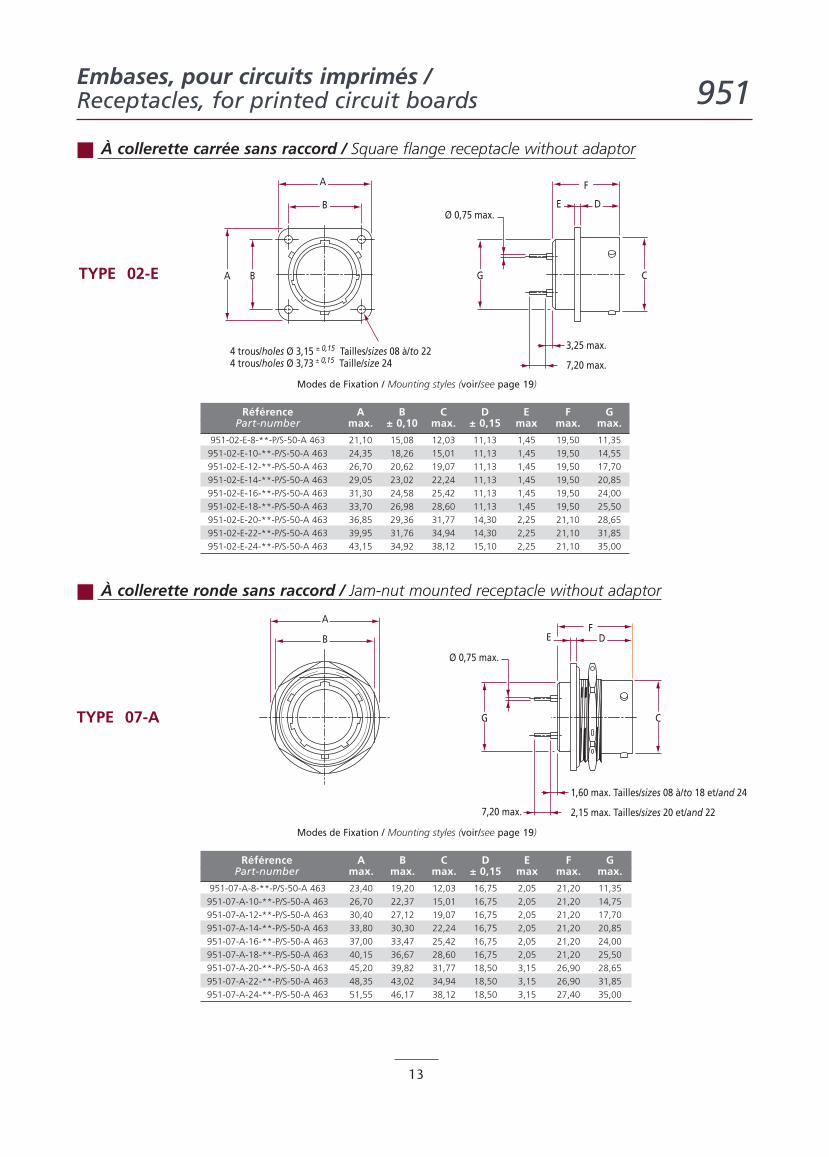
Embases, pour circuits imprimés /Receptacles, for printed circuit boards 951
13
DE
A
B
BA CG
F
4 trous/holes Ø 3,15 ± 0,15 Tailles/sizes 08 à/to 224 trous/holes Ø 3,73 ± 0,15 Taille/size 24 7,20 max.
3,25 max.
Ø 0,75 max.
B
A
DE
CG
F
2,15 max. Tailles/sizes 20 et/and 22
1,60 max. Tailles/sizes 08 à/to 18 et/and 24
Ø 0,75 max.
7,20 max.
À collerette carrée sans raccord / Square flange receptacle without adaptor
TYPE 02-E
Modes de Fixation / Mounting styles (voir/see page 19)
Référence A B C D E F GPart-number max. ± 0,10 max. ± 0,15 max max. max.
951-02-E-8-**-P/S-50-A 463 21,10 15,08 12,03 11,13 1,45 19,50 11,35
951-02-E-10-**-P/S-50-A 463 24,35 18,26 15,01 11,13 1,45 19,50 14,55
951-02-E-12-**-P/S-50-A 463 26,70 20,62 19,07 11,13 1,45 19,50 17,70
951-02-E-14-**-P/S-50-A 463 29,05 23,02 22,24 11,13 1,45 19,50 20,85
951-02-E-16-**-P/S-50-A 463 31,30 24,58 25,42 11,13 1,45 19,50 24,00
951-02-E-18-**-P/S-50-A 463 33,70 26,98 28,60 11,13 1,45 19,50 25,50
951-02-E-20-**-P/S-50-A 463 36,85 29,36 31,77 14,30 2,25 21,10 28,65
951-02-E-22-**-P/S-50-A 463 39,95 31,76 34,94 14,30 2,25 21,10 31,85
951-02-E-24-**-P/S-50-A 463 43,15 34,92 38,12 15,10 2,25 21,10 35,00
À collerette ronde sans raccord / Jam-nut mounted receptacle without adaptor
TYPE 07-A
Modes de Fixation / Mounting styles (voir/see page 19)
Référence A B C D E F GPart-number max. max. max. ± 0,15 max max. max.
951-07-A-8-**-P/S-50-A 463 23,40 19,20 12,03 16,75 2,05 21,20 11,35
951-07-A-10-**-P/S-50-A 463 26,70 22,37 15,01 16,75 2,05 21,20 14,75
951-07-A-12-**-P/S-50-A 463 30,40 27,12 19,07 16,75 2,05 21,20 17,70
951-07-A-14-**-P/S-50-A 463 33,80 30,30 22,24 16,75 2,05 21,20 20,85
951-07-A-16-**-P/S-50-A 463 37,00 33,47 25,42 16,75 2,05 21,20 24,00
951-07-A-18-**-P/S-50-A 463 40,15 36,67 28,60 16,75 2,05 21,20 25,50
951-07-A-20-**-P/S-50-A 463 45,20 39,82 31,77 18,50 3,15 26,90 28,65
951-07-A-22-**-P/S-50-A 463 48,35 43,02 34,94 18,50 3,15 26,90 31,85
951-07-A-24-**-P/S-50-A 463 51,55 46,17 38,12 18,50 3,15 27,40 35,00
Accesoires / Accessories 951
14
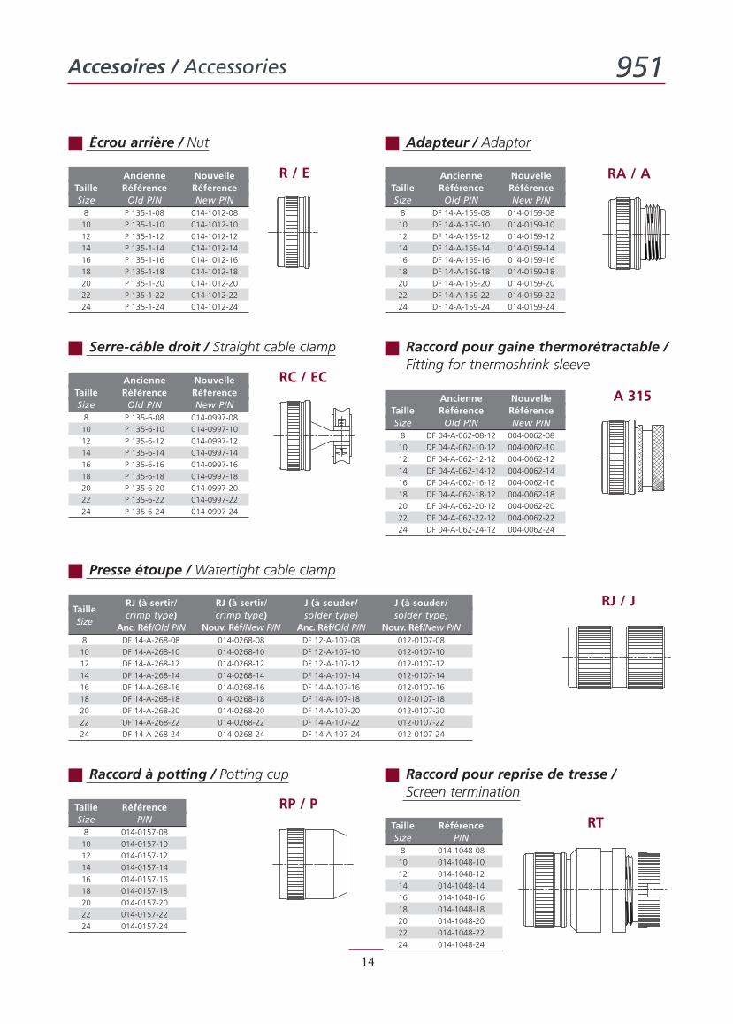
Écrou arrière / Nut Adapteur / Adaptor
Serre-câble droit / Straight cable clamp Raccord pour gaine thermorétractable /Fitting for thermoshrink sleeve
R / E RA / A
RC / ECA 315
Presse étoupe / Watertight cable clamp
Ancienne NouvelleTaille Référence RéférenceSize Old P/N New P/N8 P 135-1-08 014-1012-08
10 P 135-1-10 014-1012-10
12 P 135-1-12 014-1012-12
14 P 135-1-14 014-1012-14
16 P 135-1-16 014-1012-16
18 P 135-1-18 014-1012-18
20 P 135-1-20 014-1012-20
22 P 135-1-22 014-1012-22
24 P 135-1-24 014-1012-24
Ancienne NouvelleTaille Référence RéférenceSize Old P/N New P/N8 DF 14-A-159-08 014-0159-08
10 DF 14-A-159-10 014-0159-10
12 DF 14-A-159-12 014-0159-12
14 DF 14-A-159-14 014-0159-14
16 DF 14-A-159-16 014-0159-16
18 DF 14-A-159-18 014-0159-18
20 DF 14-A-159-20 014-0159-20
22 DF 14-A-159-22 014-0159-22
24 DF 14-A-159-24 014-0159-24
Ancienne NouvelleTaille Référence RéférenceSize Old P/N New P/N8 P 135-6-08 014-0997-08
10 P 135-6-10 014-0997-10
12 P 135-6-12 014-0997-12
14 P 135-6-14 014-0997-14
16 P 135-6-16 014-0997-16
18 P 135-6-18 014-0997-18
20 P 135-6-20 014-0997-20
22 P 135-6-22 014-0997-22
24 P 135-6-24 014-0997-24
Ancienne NouvelleTaille Référence RéférenceSize Old P/N New P/N8 DF 04-A-062-08-12 004-0062-08
10 DF 04-A-062-10-12 004-0062-10
12 DF 04-A-062-12-12 004-0062-12
14 DF 04-A-062-14-12 004-0062-14
16 DF 04-A-062-16-12 004-0062-16
18 DF 04-A-062-18-12 004-0062-18
20 DF 04-A-062-20-12 004-0062-20
22 DF 04-A-062-22-12 004-0062-22
24 DF 04-A-062-24-12 004-0062-24
RJ (à sertir/ RJ (à sertir/ J (à souder/ J (à souder/Taille
crimp type) crimp type) solder type) solder type)Size
Anc. Réf/Old P/N Nouv. Réf/New P/N Anc. Réf/Old P/N Nouv. Réf/New P/N8 DF 14-A-268-08 014-0268-08 DF 12-A-107-08 012-0107-08
10 DF 14-A-268-10 014-0268-10 DF 12-A-107-10 012-0107-10
12 DF 14-A-268-12 014-0268-12 DF 12-A-107-12 012-0107-12
14 DF 14-A-268-14 014-0268-14 DF 14-A-107-14 012-0107-14
16 DF 14-A-268-16 014-0268-16 DF 14-A-107-16 012-0107-16
18 DF 14-A-268-18 014-0268-18 DF 14-A-107-18 012-0107-18
20 DF 14-A-268-20 014-0268-20 DF 14-A-107-20 012-0107-20
22 DF 14-A-268-22 014-0268-22 DF 14-A-107-22 012-0107-22
24 DF 14-A-268-24 014-0268-24 DF 14-A-107-24 012-0107-24
RJ / J
Raccord à potting / Potting cup Raccord pour reprise de tresse /Screen termination
RP / PRT
Taille RéférenceSize P/N8 014-0157-08
10 014-0157-10
12 014-0157-12
14 014-0157-14
16 014-0157-16
18 014-0157-18
20 014-0157-20
22 014-0157-22
24 014-0157-24
Taille RéférenceSize P/N8 014-1048-08
10 014-1048-10
12 014-1048-12
14 014-1048-14
16 014-1048-16
18 014-1048-18
20 014-1048-20
22 014-1048-22
24 014-1048-24
Accesoires / Accessories 951
15
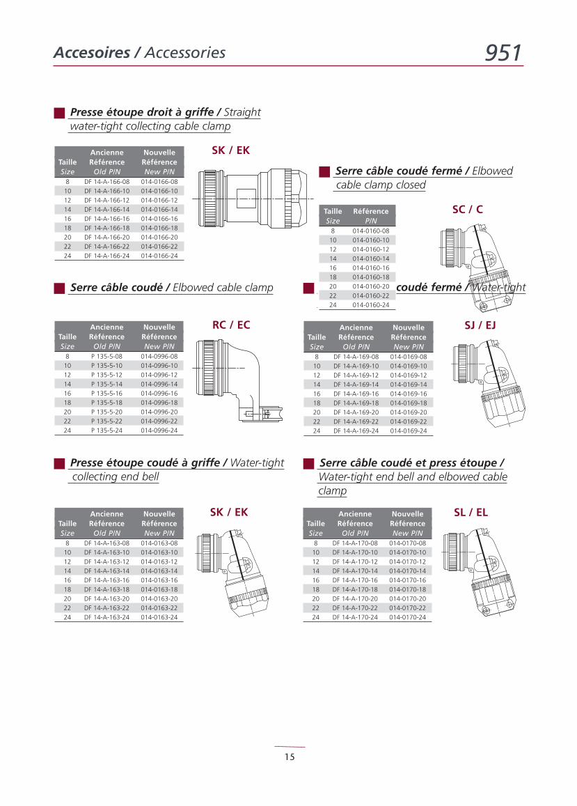
Presse étoupe droit à griffe / Straightwater-tight collecting cable clamp
SK / EKAncienne NouvelleTaille Référence RéférenceSize Old P/N New P/N8 DF 14-A-166-08 014-0166-08
10 DF 14-A-166-10 014-0166-10
12 DF 14-A-166-12 014-0166-12
14 DF 14-A-166-14 014-0166-14
16 DF 14-A-166-16 014-0166-16
18 DF 14-A-166-18 014-0166-18
20 DF 14-A-166-20 014-0166-20
22 DF 14-A-166-22 014-0166-22
24 DF 14-A-166-24 014-0166-24
RC / EC
SC / C
SJ / EJ
SK / EK
Serre câble coudé / Elbowed cable clamp
Serre câble coudé fermé / Elbowedcable clamp closed
Presse étoupe coudé fermé / Water-tightend bell
Presse étoupe coudé à griffe / Water-tightcollecting end bell
Taille RéférenceSize P/N8 014-0160-08
10 014-0160-10
12 014-0160-12
14 014-0160-14
16 014-0160-16
18 014-0160-18
20 014-0160-20
22 014-0160-22
24 014-0160-24
Serre câble coudé et press étoupe /Water-tight end bell and elbowed cableclamp
SL / EL
Ancienne NouvelleTaille Référence RéférenceSize Old P/N New P/N8 P 135-5-08 014-0996-08
10 P 135-5-10 014-0996-10
12 P 135-5-12 014-0996-12
14 P 135-5-14 014-0996-14
16 P 135-5-16 014-0996-16
18 P 135-5-18 014-0996-18
20 P 135-5-20 014-0996-20
22 P 135-5-22 014-0996-22
24 P 135-5-24 014-0996-24
Ancienne NouvelleTaille Référence RéférenceSize Old P/N New P/N8 DF 14-A-169-08 014-0169-08
10 DF 14-A-169-10 014-0169-10
12 DF 14-A-169-12 014-0169-12
14 DF 14-A-169-14 014-0169-14
16 DF 14-A-169-16 014-0169-16
18 DF 14-A-169-18 014-0169-18
20 DF 14-A-169-20 014-0169-20
22 DF 14-A-169-22 014-0169-22
24 DF 14-A-169-24 014-0169-24
Ancienne NouvelleTaille Référence RéférenceSize Old P/N New P/N8 DF 14-A-163-08 014-0163-08
10 DF 14-A-163-10 014-0163-10
12 DF 14-A-163-12 014-0163-12
14 DF 14-A-163-14 014-0163-14
16 DF 14-A-163-16 014-0163-16
18 DF 14-A-163-18 014-0163-18
20 DF 14-A-163-20 014-0163-20
22 DF 14-A-163-22 014-0163-22
24 DF 14-A-163-24 014-0163-24
Ancienne NouvelleTaille Référence RéférenceSize Old P/N New P/N8 DF 14-A-170-08 014-0170-08
10 DF 14-A-170-10 014-0170-10
12 DF 14-A-170-12 014-0170-12
14 DF 14-A-170-14 014-0170-14
16 DF 14-A-170-16 014-0170-16
18 DF 14-A-170-18 014-0170-18
20 DF 14-A-170-20 014-0170-20
22 DF 14-A-170-22 014-0170-22
24 DF 14-A-170-24 014-0170-24
Accesoires / Accessories 951
16
E
A
B
BA C
D
4 trous/holes Ø 3,15 ± 0,15 tailles/sizes 08 à/to 224 trous/holes Ø 3,73 ± 0,15 taille/size 24
4 trous/holes Ø 3,30 max. tailles/sizes 08 à/to 224 trous/holes Ø 4,30 max. taille/size 24
0,90 max.Epaisseur/Thickness
2,50 max.tailles/sizes 08 à/to 185,40 max. tailles/sizes 20 à/to 24
2,50 max.tailles/sizes 08 à/to 185,40 max. tailles/sizes 20 à/to 24
A
B
B AJ
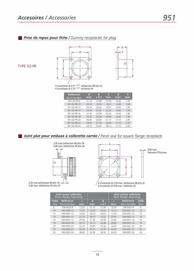
Prise de repos pour fiche / Dummy receptacles for plug
TYPE 02-PR
Joint plat pour embase à collerette carrée / Panel seal for square flange receptacle
Joint avant collerette Joint arrière colleretteFront flange mounting Rear flange mounting
Taille Référence J A B J Référence TailleSize Part-number max. max. ± 0,1 max. Part-number Size8 108-0003-8 12,50 21,10 15,08 10,90 108-0001-8 8
10 108-0003-10 15,40 24,30 18,26 14,10 108-0001-10 10
12 108-0001-12 19,50 26,70 20,62 17,20 108-0001-12 12
14 108-0001-14 22,70 29,10 23,02 20,40 108-0001-14 14
16 108-0001-16 25,90 31,30 24,58 23,60 108-0001-16 16
18 108-0003-18 29,10 33,70 26,98 26,80 108-0001-18 18
20 108-0003-20 32,30 36,90 29,36 30,60 108-0001-20 20
22 108-0003-22 35,40 40,10 31,76 33,50 108-0001-22 22
24 108-0003-24 38,60 43,30 34,92 36,30 108-0001-24 24
Référence A B C D EPart-number max. ± 0,1 max. max. max.
951-02-PR-8 21,10 15,08 12,03 14,60 1,90
951-02-PR-10 24,35 18,26 15,01 14,60 1,90
951-02-PR-12 26,70 20,62 19,07 14,60 1,90
951-02-PR-14 29,05 23,02 22,24 14,60 1,90
951-02-PR-16 31,30 24,58 25,42 14,60 1,90
951-02-PR-18 33,70 26,98 28,60 14,60 1,90
951-02-PR-20 36,85 29,36 31,77 17,10 2,45
951-02-PR-22 39,95 31,76 34,94 17,10 2,45
951-02-PR-24 43,15 34,92 38,12 17,10 2,45
Modes de fixations / Mounting styles 951
17
D
D4 trous/holes Ø 3,15 ± 0,15 tailles/sizes 08 à/to 224 trous/holes Ø 3,73 ± 0,15 taille/size 24
B
BH
Hors-tout (suivant accessoire)Overall dim. (as per accessories)
Hors-tout (suivant accessoire)Overall dim.
D
JH
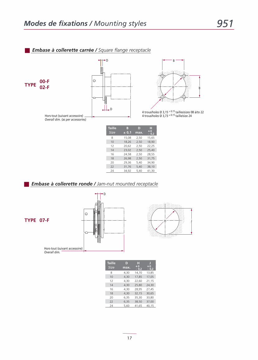
Embase à collerette carrée / Square flange receptacle
00-FTYPE 02-F
Embase à collerette ronde / Jam-nut mounted receptacle
TYPE 07-F
Taille B D HSize ± 0,1 max.
8 15,08 2,50 15,65
10 18,26 2,50 18,90
12 20,62 2,50 22,25
14 23,02 2,50 25,40
16 24,58 2,50 28,55
18 26,98 2,50 31,75
20 29,36 5,40 34,90
22 31,76 5,40 38,10
24 34,92 5,40 41,30
+0- 0,2
Taille D H JSize max.
8 4,30 14,70 13,85
10 4,30 17,85 17,05
12 4,30 22,60 21,15
14 4,30 25,80 24,30
16 4,30 28,95 27,45
18 4,30 32,15 30,65
20 6,35 35,30 33,80
22 6,35 38,50 37,00
24 5,60 41,65 40,15
+0- 0,2
+0- 0,2
Capuchons à chaînette / Protective covers with chain 951
18
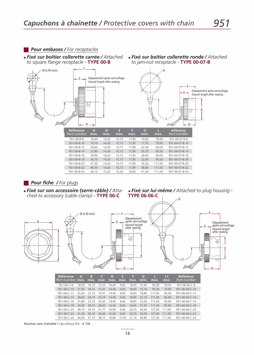
Pour embases / For receptacles
Bouchon sans chaînette / Cap without link : A 134
Ø 4,10 mini.
E
F
D
A
L
Dépassement après verrouillageOverall length after mating
F
E
D
A
L
G
Dépassement après verrouillageOverall length after mating
B
A
Ø 4,10 mini.
E
F
D
C
L
Dépassementaprès verrouillageOverall lengthafter mating
F
E
D
C
L1
G
Dépassementaprès verrouillageOverall lengthafter mating
Pour fiche / For plugs
Référence A D E F G L référencePart-number max. max. max. max. mini. max. Part-number
951-00-B-8 16,60 14,20 10,15 17,85 14,60 79,00 951-00-07-B-8
951-00-B-10 19,70 14,20 10,15 17,85 17,70 79,00 951-00-07-B-10
951-00-B-12 24,60 14,20 10,15 17,85 22,50 95,00 951-00-07-B-12
951-00-B-14 27,80 14,20 10,15 17,85 25,70 95,00 951-00-07-B-14
951-00-B-16 30,90 14,20 10,15 17,85 28,90 95,00 951-00-07-B-16
951-00-B-18 34,10 14,20 10,15 17,85 32,00 95,00 951-00-07-B-18
951-00-B-20 37,30 14,20 10,15 17,85 35,20 111,00 951-00-07-B-20
951-00-B-22 40,50 14,20 10,15 17,85 38,40 111,00 951-00-07-B-22
951-00-B-24 44,10 15,20 10,30 18,85 41,60 111,00 951-00-07-B-24
Référence A B C D E F G L L1 RéférencePart-number max. max. max. max. max. max. mini. max. max. Part-number
951-06-C-8 18,30 16,10 12,03 14,40 9,60 18,65 12,45 95,00 79,00 951-06-06-C-8
951-06-C-10 21,50 18,10 15,01 14,40 9,60 18,65 15,70 95,00 79,00 951-06-06-C-10
951-06-C-12 25,40 22,10 19,07 14,40 9,60 18,65 18,85 111,00 95,00 951-06-06-C-12
951-06-C-14 28,60 24,10 22,24 14,40 9,60 18,65 22,10 111,00 95,00 951-06-06-C-14
951-06-C-16 31,80 27,10 25,42 14,40 9,60 18,65 25,50 111,00 95,00 951-06-06-C-16
951-06-C-18 34,90 30,10 28,60 14,40 9,60 18,65 27,35 111,00 95,00 951-06-06-C-18
951-06-C-20 38,10 33,10 31,77 16,00 9,60 20,25 30,40 127,00 111,00 951-06-06-C-20
951-06-C-22 41,30 36,10 34,94 16,00 9,60 20,25 33,30 127,00 111,00 951-06-06-C-22
951-06-C-24 44,50 41,10 38,12 16,80 10,45 21,10 36,80 127,00 111,00 951-06-06-C-24
• Fixé sur boîtier collerette carrée / Attachedto square flange receptacle - TYPE 00-B
• Fixé sur boîtier collerette ronde / Attachedto jam-nut receptacle - TYPE 00-07-B
• Fixé sur son accessoire (serre-câble) / Atta-ched to accessory (cable clamp) - TYPE 06-C
• Fixé sur lui-même / Attached to plug housing -TYPE 06-06-C
Capuchons à tresse nylon / Protective covers withnylon braid 951
19
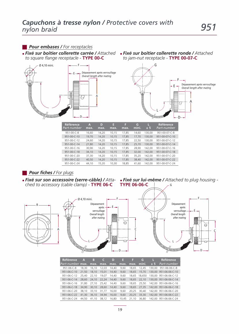
Pour embases / For receptacles
Ø 4,10 mini.
E
F
D
A
Dépassement après verrouillageOverall length after mating
F
E
D
A
L
G
Dépassement après verrouillageOverall length after mating
F
D
C
L
G
E
Dépassementaprès
verrouillageOverall length
after mating
B
A
Ø 4,10 mini.
E
F
D
C
L
Dépassementaprès
verrouillageOverall length
after mating
Pour fiches / For plugs
Référence A D E F G L RéférencePart-number max. max. max. max. mini. ± 5 Part-number
951-00-C-8 16,60 14,20 10,15 17,85 14,60 130,00 951-00-07-C-8
951-00-C-10 19,70 14,20 10,15 17,85 17,70 130,00 951-00-07-C-10
951-00-C-12 24,60 14,20 10,15 17,85 22,50 130,00 951-00-07-C-12
951-00-C-14 27,80 14,20 10,15 17,85 25,70 130,00 951-00-07-C-14
951-00-C-16 30,90 14,20 10,15 17,85 28,90 142,00 951-00-07-C-16
951-00-C-18 34,10 14,20 10,15 17,85 32,00 142,00 951-00-07-C-18
951-00-C-20 37,30 14,20 10,15 17,85 35,20 142,00 951-00-07-C-20
951-00-C-22 40,50 14,20 10,15 17,85 38,40 142,00 951-00-07-C-22
951-00-C-24 44,10 15,20 10,30 18,85 41,60 142,00 951-00-07-C-24
Référence A B C D E F G L RéférencePart-number max. max. max. max. max. max. mini. ± 5 Part-number
951-06-C-8 18,30 16,10 12,03 14,40 9,60 18,65 12,45 130,00 951-06-06-C-8
951-06-C-10 21,50 18,10 15,01 14,40 9,60 18,65 15,70 130,00 951-06-06-C-10
951-06-C-12 25,40 22,10 19,07 14,40 9,60 18,65 18,650 130,00 951-06-06-C-12
951-06-C-14 28,60 24,10 22,24 14,40 9,60 18,65 22,10 130,00 951-06-06-C-14
951-06-C-16 31,80 27,10 25,42 14,40 9,60 18,65 25,50 142,00 951-06-06-C-16
951-06-C-18 34,90 30,10 28,60 14,40 9,60 18,65 27,35 142,00 951-06-06-C-18
951-06-C-20 38,10 33,10 31,77 16,00 9,60 20,25 30,40 142,00 951-06-06-C-20
951-06-C-22 41,30 36,10 34,94 16,00 9,60 20,25 33,30 142,00 951-06-06-C-22
951-06-C-24 44,50 41,10 38,12 16,80 10,45 21,10 36,80 142,00 951-06-06-C-24
• Fixé sur boîtier collerette carrée / Attachedto square flange receptacle - TYPE 00-C
• Fixé sur boîtier collerette ronde / Attachedto jam-nut receptacle - TYPE 00-07-C
• Fixé sur son accessoire (serre-câble) / Atta-ched to accessory (cable clamp) - TYPE 06-C
• Fixé sur lui-même / Attached to plug housing -TYPE 06-06-C
Contacts / Contacts 951
20
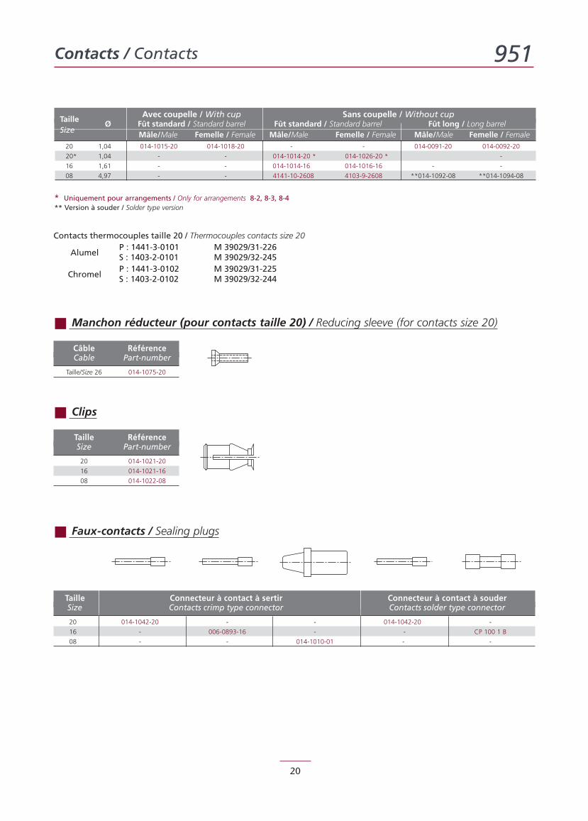
Avec coupelle / With cup Sans coupelle / Without cupTaille
Ø Fût standard / Standard barrel Fût standard / Standard barrel Fût long / Long barrelSize
Mâle/Male Femelle / Female Mâle/Male Femelle / Female Mâle/Male Femelle / Female20 1,04 014-1015-20 014-1018-20 - - 014-0091-20 014-0092-20
20* 1,04 - - 014-1014-20 * 014-1026-20 * -
16 1,61 - - 014-1014-16 014-1016-16 - -
08 4,97 - - 4141-10-2608 4103-9-2608 **014-1092-08 **014-1094-08
* Uniquement pour arrangements / Only for arrangements 8-2, 8-3, 8-4** Version à souder / Solder type version
Taille Connecteur à contact à sertir Connecteur à contact à souderSize Contacts crimp type connector Contacts solder type connector
20 014-1042-20 - - 014-1042-20 -
16 - 006-0893-16 - - CP 100 1 B
08 - - 014-1010-01 - -
Câble RéférenceCable Part-number
Taille/Size 26 014-1075-20
Taille RéférenceSize Part-number
20 014-1021-20
16 014-1021-16
08 014-1022-08
Contacts thermocouples taille 20 / Thermocouples contacts size 20P : 1441-3-0101 M 39029/31-226
Alumel S : 1403-2-0101 M 39029/32-245P : 1441-3-0102 M 39029/31-225
Chromel S : 1403-2-0102 M 39029/32-244
Manchon réducteur (pour contacts taille 20) / Reducing sleeve (for contacts size 20)
Clips
Faux-contacts / Sealing plugs
Outillages / Tools 951
21
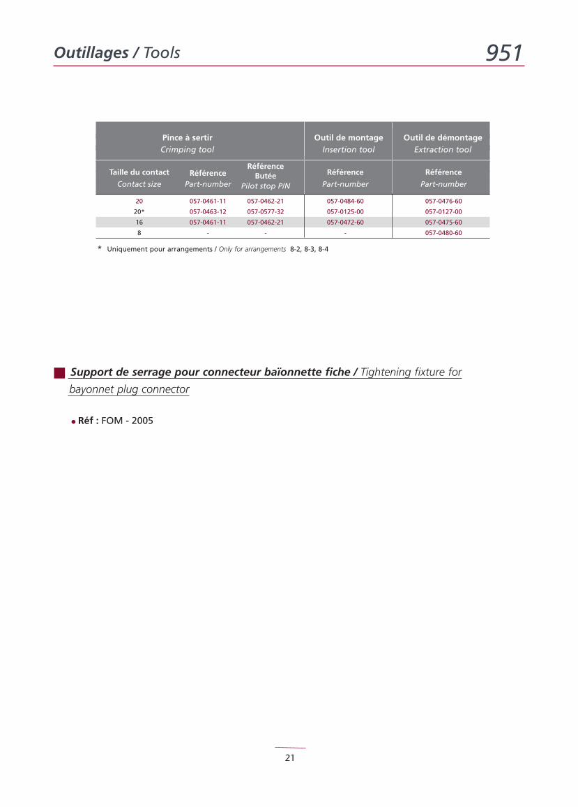
Support de serrage pour connecteur baïonnette fiche / Tightening fixture for
bayonnet plug connector
• Réf : FOM - 2005
Pince à sertir Outil de montage Outil de démontageCrimping tool Insertion tool Extraction tool
RéférenceTaille du contact Référence Butée Référence Référence
Contact size Part-number Pilot stop P/N Part-number Part-number
20 057-0461-11 057-0462-21 057-0484-60 057-0476-60
20* 057-0463-12 057-0577-32 057-0125-00 057-0127-00
16 057-0461-11 057-0462-21 057-0472-60 057-0475-60
8 - - - 057-0480-60
* Uniquement pour arrangements / Only for arrangements 8-2, 8-3, 8-4
Contacts et outillages coaxiauxCoaxial contacts and tools 951
22
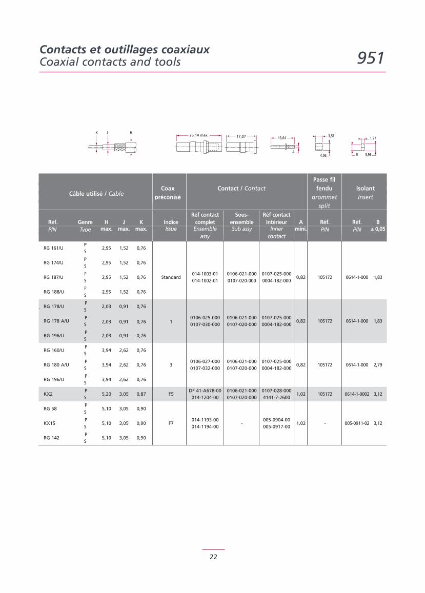
Passe filCoax Contact / Contact fendu Isolant
Câble utilisé / Cable préconisé grommet Insertsplit
Réf contact Sous- Réf contactRéf. Genre H J K Indice complet ensemble Intérieur A Réf. Réf. BP/N Type max. max. max. Issue Ensemble Sub assy Inner mini. P/N P/N ± 0,05
assy contactP
RG 161/US
2,95 1,52 0,76
PRG 174/U
S2,95 1,52 0,76
P 014-1003-01 0106-021-000 0107-025-0000,82 105172 0614-1-000 1,83RG 187/U
S2,95 1,52 0,76 Standard
014-1002-01 0107-020-000 0004-182-000
PRG 188/U
S2,95 1,52 0,76
P`RG 178/U
S2,03 0,91 0,76
P 0106-025-000 0106-021-000 0107-025-000RG 178 A/U
S 2,03 0,91 0,76 1 0107-030-000 0107-020-000 0004-182-0000,82 105172 0614-1-000 1,83
PRG 196/U
S2,03 0,91 0,76
PRG 160/U
S3,94 2,62 0,76
P 0106-027-000 0106-021-000 0107-025-000RG 180 A/U
S3,94 2,62 0,76 3
0107-032-000 0107-020-000 0004-182-0000,82 105172 0614-1-000 2,79
PRG 196/U
S3,94 2,62 0,76
P DF 41-A678-00 0106-021-000 0107-028-000KX2
S5,20 3,05 0,87 F5
014-1204-00 0107-020-000 4141-7-26001,02 105172 0614-1-0002 3,12
PRG 58
S5,10 3,05 0,90
P 014-1193-00-
005-0904-00KX15
S5,10 3,05 0,90 F7
014-1194-00 005-0917-001,02 - 005-0911-02 3,12
PRG 142
S5,10 3,05 0,90
K J H
A
13,6417,07 3,56
4,06
1,27
3,96B
26,14 max.
23
F
8.13
E G
23,65
7,52
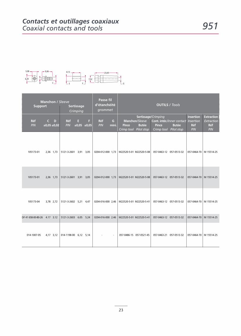
Manchon / Sleeve Passe fil
Support Sertissage d’étanchéité OUTILS / Tools
Crimping grommet
Sertissage/Crimping Insertion ExtractionRéf C D Réf E F Réf G Manchon/Sleeve Cont. intér./Inner contact Insertion ExtractionP/N ±0,05 ±0,02 P/N ±0,05 ±0,05 P/N mini. Pince Butée Pince Butée Réf Réf
Crimp tool Pilot stop Crimp tool Pilot stop P/N P/N
105173-01 2,36 1,73 5121-3-2601 3,91 3,05 0204-012-000 1,73 M22520-5-01 M22520-5-08 057-0463-12 057-0513-32 057-0464-70 M 15514-25
105173-01 2,36 1,73 5121-3-2601 3,91 3,05 0204-012-000 1,73 M22520-5-01 M22520-5-08 057-0463-12 057-0513-32 057-0464-70 M 15514-25
105173-04 3,78 2,72 5121-3-2602 5,21 4,47 0204-016-000 2,46 M22520-5-01 M22520-5-41 057-0463-12 057-0513-32 057-0464-70 M 15514-25
DF 41 658-00-80-26 4,17 3,12 5121-3-2603 6,05 5,24 0204-016-000 2,46 M22520-5-01 M22520-5-41 057-0463-12 057-0513-32 057-0464-70 M 15514-25
014-1007-05 4,17 3,12 014-1198-00 6,12 5,14 - - 057-0486-15 057-0521-45 057-0463-21 057-0513-32 057-0464-70 M 15514-25
5,08
D C
9,06
6,35
Contacts et outillages coaxiauxCoaxial contacts and tools 951
Caractéristiques techniques / Technical characteristics 951-H
24
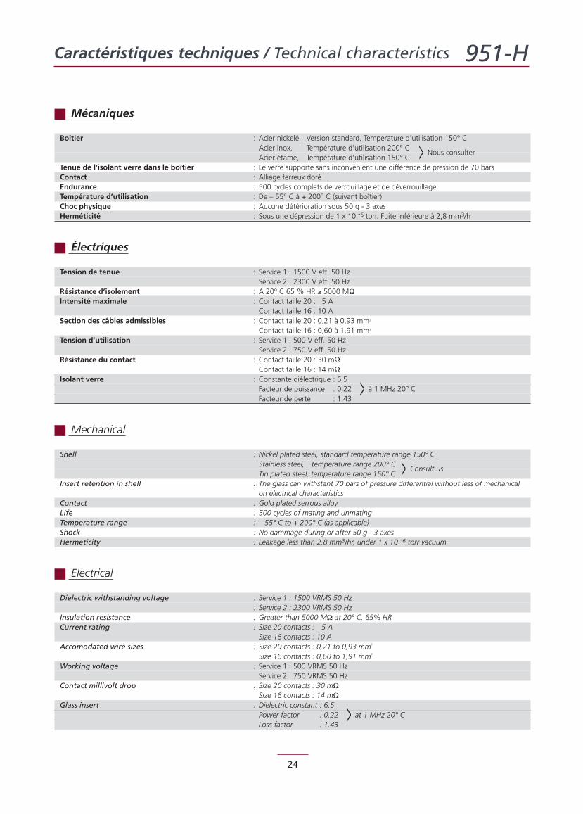
Shell : Nickel plated steel, standard temperature range 150° CStainless steel, temperature range 200° CTin plated steel, temperature range 150° C > Consult us
Insert retention in shell : The glass can withstant 70 bars of pressure differential without less of mechanicalon electrical characteristics
Contact : Gold plated serrous alloyLife : 500 cycles of mating and unmatingTemperature range : – 55° C to + 200° C (as applicable)Shock : No dammage during or after 50 g - 3 axesHermeticity : Leakage less than 2,8 mm3/hr, under 1 x 10 -6 torr vacuum
Dielectric withstanding voltage : Service 1 : 1500 VRMS 50 Hz: Service 2 : 2300 VRMS 50 Hz
Insulation resistance : Greater than 5000 MΩ at 20° C, 65% HRCurrent rating : Size 20 contacts : 5 A
Size 16 contacts : 10 AAccomodated wire sizes : Size 20 contacts : 0,21 to 0,93 mm2
Size 16 contacts : 0,60 to 1,91 mm2
Working voltage : Service 1 : 500 VRMS 50 HzService 2 : 750 VRMS 50 Hz
Contact millivolt drop : Size 20 contacts : 30 mΩSize 16 contacts : 14 mΩ
Glass insert : Dielectric constant : 6,5Power factor : 0,22 at 1 MHz 20° CLoss factor : 1,43
>
Boîtier : Acier nickelé, Version standard, Température d'utilisation 150° CAcier inox, Température d'utilisation 200° CAcier étamé, Température d'utilisation 150° C > Nous consulter
Tenue de l'isolant verre dans le boîtier : Le verre supporte sans inconvénient une différence de pression de 70 barsContact : Alliage ferreux doréEndurance : 500 cycles complets de verrouillage et de déverrouillageTempérature d’utilisation : De – 55° C à + 200° C (suivant boîtier)Choc physique : Aucune détérioration sous 50 g - 3 axesHerméticité : Sous une dépression de 1 x 10 -6 torr. Fuite inférieure à 2,8 mm3/h
Tension de tenue : Service 1 : 1500 V eff. 50 HzService 2 : 2300 V eff. 50 Hz
Résistance d’isolement : A 20° C 65 % HR ≥ 5000 MΩIntensité maximale : Contact taille 20 : 5 A
Contact taille 16 : 10 ASection des câbles admissibles : Contact taille 20 : 0,21 à 0,93 mm2
Contact taille 16 : 0,60 à 1,91 mm2
Tension d’utilisation : Service 1 : 500 V eff. 50 HzService 2 : 750 V eff. 50 Hz
Résistance du contact : Contact taille 20 : 30 mΩContact taille 16 : 14 mΩ
Isolant verre : Constante diélectrique : 6,5Facteur de puissance : 0,22 à 1 MHz 20° CFacteur de perte : 1,43
>
Mécaniques
Électriques
Mechanical
Electrical
Système de référence / Part numbering system 951-H
25
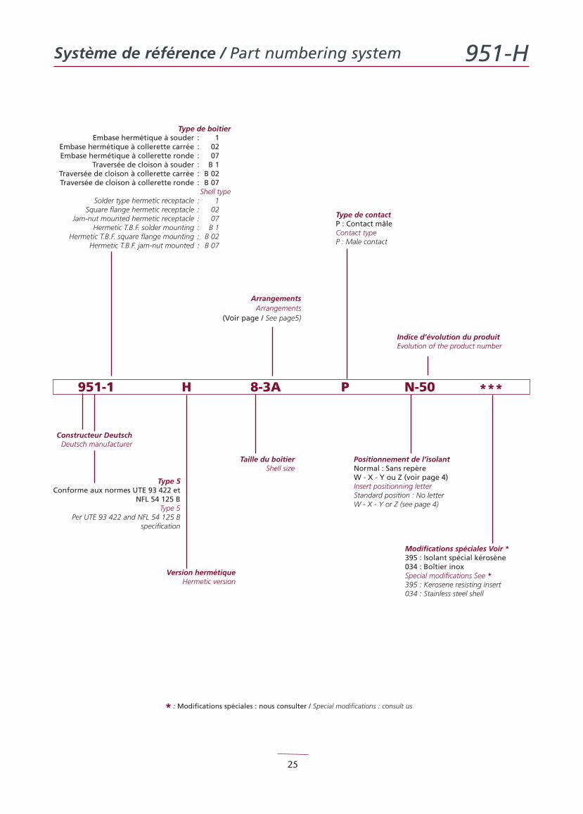
Positionnement de l’isolantNormal : Sans repèreW - X - Y ou Z (voir page 4)Insert positionning letterStandard position : No letterW - X - Y or Z (see page 4)
Modifications spéciales Voir *395 : Isolant spécial kérosène034 : Boîtier inoxSpecial modifications See *395 : Kerosene resisting insert034 : Stainless steel shell
951-1 H 8-3A P N-50 ***
Taille du boîtierShell size
Indice d’évolution du produitEvolution of the product number
Type de boîtierEmbase hermétique à souder : 1
Embase hermétique à collerette carrée : 02Embase hermétique à collerette ronde : 07
Traversée de cloison à souder : B 1Traversée de cloison à collerette carrée : B 02Traversée de cloison à collerette ronde : B 07
Shell typeSolder type hermetic receptacle : 1
Square flange hermetic receptacle : 02Jam-nut mounted hermetic receptacle : 07
Hermetic T.B.F. solder mounting : B 1Hermetic T.B.F. square flange mounting : B 02
Hermetic T.B.F. jam-nut mounted : B 07
Version hermétiqueHermetic version
Type de contactP : Contact mâleContact typeP : Male contact
ArrangementsArrangements
(Voir page / See page5)
Type 5Conforme aux normes UTE 93 422 et
NFL 54 125 BType 5
Per UTE 93 422 and NFL 54 125 Bspecification
* : Modifications spéciales : nous consulter / Special modifications : consult us
Constructeur DeutschDeutsch manufacturer
Embases hermétiques / Hermetic receptacles 951-H
26
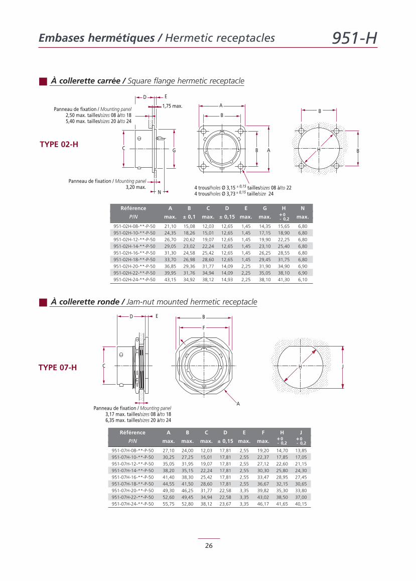
Référence A B C D E G H N
P/N max. ± 0,1 max. ± 0,15 max. max. max.
951-02H-08-**-P-50 21,10 15,08 12,03 12,65 1,45 14,35 15,65 6,80
951-02H-10-**-P-50 24,35 18,26 15,01 12,65 1,45 17,15 18,90 6,80
951-02H-12-**-P-50 26,70 20,62 19,07 12,65 1,45 19,90 22,25 6,80
951-02H-14-**-P-50 29,05 23,02 22,24 12,65 1,45 23,10 25,40 6,80
951-02H-16-**-P-50 31,30 24,58 25,42 12,65 1,45 26,25 28,55 6,80
951-02H-18-**-P-50 33,70 26,98 28,60 12,65 1,45 29,45 31,75 6,80
951-02H-20-**-P-50 36,85 29,36 31,77 14,09 2,25 31,90 34,90 6,90
951-02H-22-**-P-50 39,95 31,76 34,94 14,09 2,25 35,05 38,10 6,90
951-02H-24-**-P-50 43,15 34,92 38,12 14,93 2,25 38,10 41,30 6,10
Référence A B C D E F H J
P/N max. max. max. ± 0,15 max. max.
951-07H-08-**-P-50 27,10 24,00 12,03 17,81 2,55 19,20 14,70 13,85
951-07H-10-**-P-50 30,25 27,25 15,01 17,81 2,55 22,37 17,85 17,05
951-07H-12-**-P-50 35,05 31,95 19,07 17,81 2,55 27,12 22,60 21,15
951-07H-14-**-P-50 38,20 35,15 22,24 17,81 2,55 30,30 25,80 24,30
951-07H-16-**-P-50 41,40 38,30 25,42 17,81 2,55 33,47 28,95 27,45
951-07H-18-**-P-50 44,55 41,50 28,60 17,81 2,55 36,67 32,15 30,65
951-07H-20-**-P-50 49,30 46,25 31,77 22,58 3,35 39,82 35,30 33,80
951-07H-22-**-P-50 52,60 49,45 34,94 22,58 3,35 43,02 38,50 37,00
951-07H-24-**-P-50 55,75 52,80 38,12 23,67 3,35 46,17 41,65 40,15
À collerette carrée / Square flange hermetic receptacle
À collerette ronde / Jam-nut mounted hermetic receptacle
D E
A
B
B AGC
4 trous/holes Ø 3,15 ± 0,15 tailles/sizes 08 à/to 224 trous/holes Ø 3,73 ± 0,15 taille/size 24
1,75 max.
Panneau de fixation / Mounting panel3,20 max.
B
BH
N
Panneau de fixation / Mounting panel2,50 max. tailles/sizes 08 à/to 185,40 max. tailles/sizes 20 à/to 24
C
D E
A
F
B
JH
Panneau de fixation / Mounting panel3,17 max. tailles/sizes 08 à/to 186,35 max. tailles/sizes 20 à/to 24
TYPE 02-H
TYPE 07-H
+0- 0,2
+0- 0,2
+0- 0,2
Traversées de cloison / T.B.F. 951-H
27
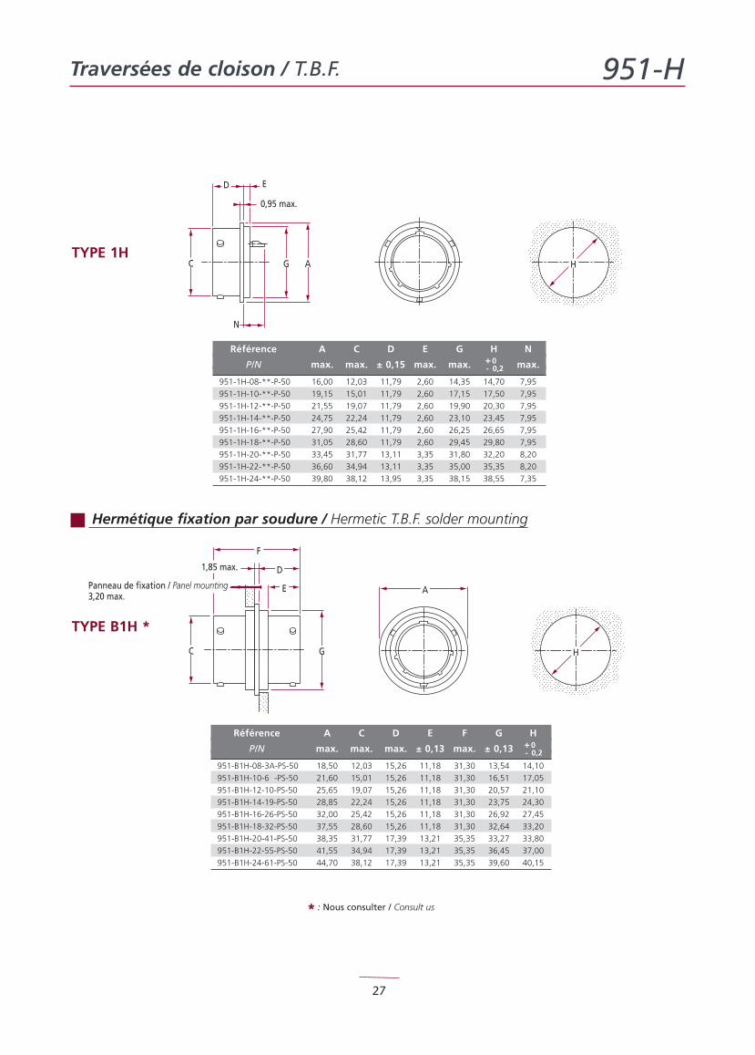
Référence A C D E G H N
P/N max. max. ± 0,15 max. max. max.
951-1H-08-**-P-50 16,00 12,03 11,79 2,60 14,35 14,70 7,95
951-1H-10-**-P-50 19,15 15,01 11,79 2,60 17,15 17,50 7,95
951-1H-12-**-P-50 21,55 19,07 11,79 2,60 19,90 20,30 7,95
951-1H-14-**-P-50 24,75 22,24 11,79 2,60 23,10 23,45 7,95
951-1H-16-**-P-50 27,90 25,42 11,79 2,60 26,25 26,65 7,95
951-1H-18-**-P-50 31,05 28,60 11,79 2,60 29,45 29,80 7,95
951-1H-20-**-P-50 33,45 31,77 13,11 3,35 31,80 32,20 8,20
951-1H-22-**-P-50 36,60 34,94 13,11 3,35 35,00 35,35 8,20
951-1H-24-**-P-50 39,80 38,12 13,95 3,35 38,15 38,55 7,35
Hermétique fixation par soudure / Hermetic T.B.F. solder mounting
D E
C
0,95 max.
N
G HA
C
1,85 max.
Panneau de fixation / Panel mounting3,20 max.
D
E
F
A
G H
Référence A C D E F G H
P/N max. max. max. ± 0,13 max. ± 0,13
951-B1H-08-3A-PS-50 18,50 12,03 15,26 11,18 31,30 13,54 14,10
951-B1H-10-6 -PS-50 21,60 15,01 15,26 11,18 31,30 16,51 17,05
951-B1H-12-10-PS-50 25,65 19,07 15,26 11,18 31,30 20,57 21,10
951-B1H-14-19-PS-50 28,85 22,24 15,26 11,18 31,30 23,75 24,30
951-B1H-16-26-PS-50 32,00 25,42 15,26 11,18 31,30 26,92 27,45
951-B1H-18-32-PS-50 37,55 28,60 15,26 11,18 31,30 32,64 33,20
951-B1H-20-41-PS-50 38,35 31,77 17,39 13,21 35,35 33,27 33,80
951-B1H-22-55-PS-50 41,55 34,94 17,39 13,21 35,35 36,45 37,00
951-B1H-24-61-PS-50 44,70 38,12 17,39 13,21 35,35 39,60 40,15
* : Nous consulter / Consult us
TYPE 1H
TYPE B1H *
+0- 0,2
+0- 0,2
Traversées de cloison / T.B.F. 951-H
28
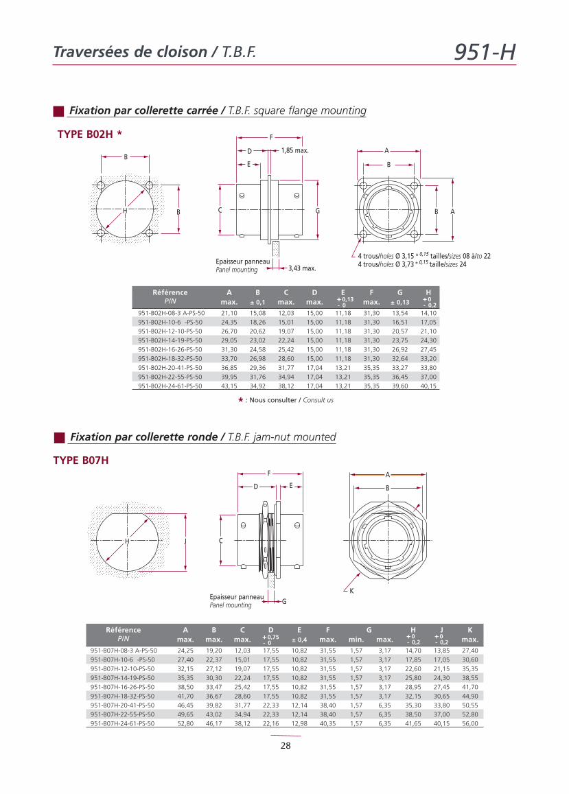
Référence A B C D E F G HP/N max. ± 0,1 max. max. max. ± 0,13
951-B02H-08-3 A-PS-50 21,10 15,08 12,03 15,00 11,18 31,30 13,54 14,10
951-B02H-10-6 -PS-50 24,35 18,26 15,01 15,00 11,18 31,30 16,51 17,05
951-B02H-12-10-PS-50 26,70 20,62 19,07 15,00 11,18 31,30 20,57 21,10
951-B02H-14-19-PS-50 29,05 23,02 22,24 15,00 11,18 31,30 23,75 24,30
951-B02H-16-26-PS-50 31,30 24,58 25,42 15,00 11,18 31,30 26,92 27,45
951-B02H-18-32-PS-50 33,70 26,98 28,60 15,00 11,18 31,30 32,64 33,20
951-B02H-20-41-PS-50 36,85 29,36 31,77 17,04 13,21 35,35 33,27 33,80
951-B02H-22-55-PS-50 39,95 31,76 34,94 17,04 13,21 35,35 36,45 37,00
951-B02H-24-61-PS-50 43,15 34,92 38,12 17,04 13,21 35,35 39,60 40,15
C
Epaisseur panneauPanel mounting
B
BH G
D
F
1,85 max.
3,43 max.
A
B A
4 trous/holes Ø 3,15 ± 0,15 tailles/sizes 08 à/to 224 trous/holes Ø 3,73 ± 0,15 taille/sizes 24
E B
Fixation par collerette carrée / T.B.F. square flange mounting
Fixation par collerette ronde / T.B.F. jam-nut mounted
C
Epaisseur panneauPanel mounting
F
ED
G
JH
K
B
A
* : Nous consulter / Consult us
TYPE B02H *
TYPE B07H
Référence A B C D E F G H J KP/N max. max. max. ± 0,4 max. min. max. max.
951-B07H-08-3 A-PS-50 24,25 19,20 12,03 17,55 10,82 31,55 1,57 3,17 14,70 13,85 27,40
951-B07H-10-6 -PS-50 27,40 22,37 15,01 17,55 10,82 31,55 1,57 3,17 17,85 17,05 30,60
951-B07H-12-10-PS-50 32,15 27,12 19,07 17,55 10,82 31,55 1,57 3,17 22,60 21,15 35,35
951-B07H-14-19-PS-50 35,35 30,30 22,24 17,55 10,82 31,55 1,57 3,17 25,80 24,30 38,55
951-B07H-16-26-PS-50 38,50 33,47 25,42 17,55 10,82 31,55 1,57 3,17 28,95 27,45 41,70
951-B07H-18-32-PS-50 41,70 36,67 28,60 17,55 10,82 31,55 1,57 3,17 32,15 30,65 44,90
951-B07H-20-41-PS-50 46,45 39,82 31,77 22,33 12,14 38,40 1,57 6,35 35,30 33,80 50,55
951-B07H-22-55-PS-50 49,65 43,02 34,94 22,33 12,14 38,40 1,57 6,35 38,50 37,00 52,80
951-B07H-24-61-PS-50 52,80 46,17 38,12 22,16 12,98 40,35 1,57 6,35 41,65 40,15 56,00
+0,75- 0
+0- 0,2
+0- 0,2
+0,13- 0
+0- 0,2
Joint plat / Panel seal 951-H
29
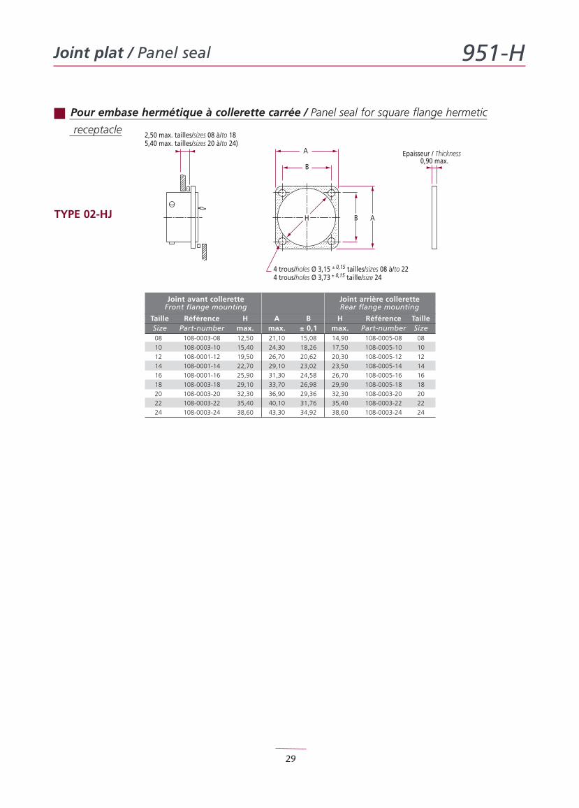
2,50 max. tailles/sizes 08 à/to 185,40 max. tailles/sizes 20 à/to 24)
A
B
B AH
4 trous/holes Ø 3,15 ± 0,15 tailles/sizes 08 à/to 224 trous/holes Ø 3,73 ± 0,15 taille/size 24
Epaisseur / Thickness0,90 max.
TYPE 02-HJ
Joint avant collerette Joint arrière colleretteFront flange mounting Rear flange mounting
Taille Référence H A B H Référence TailleSize Part-number max. max. ± 0,1 max. Part-number Size08 108-0003-08 12,50 21,10 15,08 14,90 108-0005-08 08
10 108-0003-10 15,40 24,30 18,26 17,50 108-0005-10 10
12 108-0001-12 19,50 26,70 20,62 20,30 108-0005-12 12
14 108-0001-14 22,70 29,10 23,02 23,50 108-0005-14 14
16 108-0001-16 25,90 31,30 24,58 26,70 108-0005-16 16
18 108-0003-18 29,10 33,70 26,98 29,90 108-0005-18 18
20 108-0003-20 32,30 36,90 29,36 32,30 108-0003-20 20
22 108-0003-22 35,40 40,10 31,76 35,40 108-0003-22 22
24 108-0003-24 38,60 43,30 34,92 38,60 108-0003-24 24
Pour embase hermétique à collerette carrée / Panel seal for square flange hermetic
receptacle

E-mail : [email protected] - Tel. : +33 1 34 61 80 84www.inogia.com