MAXI-CLADDING - granitifiandre.com · I sistemi di facciata per le lastre MAXIMUM, tipologie di...
62
FACADES SYSTEMS, VARIOUS APPLICATIONS MA X I-CLADDING I sistemi di facciata per le lastre MAXIMUM, tipologie di applicazione
Transcript of MAXI-CLADDING - granitifiandre.com · I sistemi di facciata per le lastre MAXIMUM, tipologie di...

1
FACADES SYSTEM, VARIOUSAPPLICATIONS
MAXI-CLADDINGI sistemi di facciata per le lastre MAXIMUM, tipologie di applicazione
FACADES SYSTEMS, VARIOUSAPPLICATIONS
MAXI-CLADDINGI sistemi di facciata per le lastre MAXIMUM, tipologie di applicazione

1
FAÇADES SYSTEMS, VARIOUSAPPLICATIONS
MAXI-CLADDINGI sistemi di facciata per le lastre MAXIMUM, tipologie di applicazione

2

3
04 L’INVOLUCRO EDILIZIO
07 TIPOLOGIE DI APPLICAZIONE LASTRE MAXIMUM A PARETE
10 SISTEMA SAFETY CLIP
14 Utilizzo sistema Safety Clip
15 Rivestimento Safety Clip range dimensionale e utilizzo
14 SISTEMA A CAPPOTTO
20 Sequenza di posa sistema a Cappotto
22 Utilizzo sistema a Cappotto
23 Rivestimento a Cappotto range dimensionale e utilizzo
24 SISTEMA MICRO
29 Sequenza di posa sistema Micro
30 Utilizzo sistema Micro
31 Rivestimento Micro range dimensionale e utilizzo
32 FACCIATA VENTILATA
34 Utilizzo facciata ventilata
36 SISTEMA GHC MAXI FRAME
43 Sequenza di posa sistema GHC Maxi Frame
44 Logistica di cantiere sistema GHC Maxi Frame
45 Rivestimento GHC Maxi Frame range dimensionale e utilizzo
46 SISTEMA GHL MAXI LIGHT
50 Sequenza di posa sistema GHL Maxi Light
52 Logistica di cantiere sistema GHL Maxi Light
53 Rivestimento GHL Maxi Light range dimensionale e utilizzo
54 TAVOLA SINOTTICA: DOVE E QUANDO UTILIZZARE I SISTEMI DI RIVESTIMENTO
56 MAXIMUM COLLECTION
58 GLOSSARIO
05 ARCHITECTURAL ENVELOPES
09 TYPES OF WALL APPLICATION FOR MAXIMUM SLABS
10 SAFETY CLIP SYSTEM
14 Safety Clip system use
15 Safety Clip covering size range and use
17 THERMAL CLADDING SYSTEM
20 Cladding System laying sequence
22 Cladding System use
23 Cladding System covering size range and use
25 MICRO SYSTEM
29 Micro system laying sequence
30 Micro system use
31 Micro covering size range and use
32 VENTILATED FAÇADE
35 ventilated façades use
37 GHC MAXI FRAME SYSTEM
43 GHC Maxi Frame system laying sequence
44 GHC Maxi Frame site logistics
45 GHC Maxi Frame covering size range and use
46 GHL MAXI LIGHT SYSTEM
50 GHL Maxi Light system laying sequence
52 GHL Maxi Light site logistics
53 GHL Maxi Light covering size range and use
54 SYNOPTIC TABLE: EHERE AND WHEN TO USE THE CLADDING SYSTEM
56 MAXIMUM COLLECTION
59 GLOSSARY

4
ARIA CALDAHot air
ARIA FREDDACold air
L’INVOLUCRO ARCHITETTONICOL’involucro è l’elemento della costruzione che delimita lo spazio abitato, separa il «dentro» dal «fuori» e media, connette e separa l’interno e l’esterno. Esso determina quindi il rapporto tra edificio e ambiente, come un vero e proprio filtro architettonico e costruttivo, regolando di conseguenza anche i rapporti tra le persone che vivono l’edificio e l’ambiente circostante.
L’involucro architettonico rappresenta da sempre un luogo privilegiato per l’innovazione, sebbene sia ricco di complessità. La continua ricerca di forme e tecnologie particolari e avanzate, la necessità sempre più spinta di personalizzazione e il suo essere il biglietto da visita dell’edificio nei confronti del contesto ambientale e sociale, rende questa parte della costruzione di straordinaria importanza e rilevanza, e con essa i materiali e i sistemi costruttivi con cui è realizzata.
L’attuale funzione di filtro dell’involucro edilizio è anche relativa al controllo dinamico degli scambi energetici che avvengono costantemente tra interno ed esterno, rendendo quindi l’involucro una interfaccia dinamica in continua interazione con i fattori climatici e ambientali esterni come una vera e propria pelle, demandando ad esso e ai sistemi con cui è costruito, l’ottimizzazione del comfort interno degli spazi e la massimizzazione dei requisiti prestazionali dell’edificio. L’efficienza di un involucro edilizio in questo scenario, pertanto, può essere ritrovata nella sua capacità di reagire in modo flessibile alle condizioni ambientali in continua variazione, minimizzando le dispersioni termiche in inverno e l’eccessivo guadagno di calore in estate.
Attualmente tale aspetto assume una rilevanza particolare, vista l’attenzione crescente verso il contenimento energetico e il comfort degli spazi, temi che sempre più interessano architetti e progettisti, investitori e costruttori, ma anche clienti e utenti finali. Le soluzioni tecnologiche ed architettoniche che il mercato oggi richiede sono, dunque, finalizzate non solo a realizzare una architettura di qualità, ma anche energeticamente efficiente, grazie alla possibilità di sposare qualità e funzionalità in un involucro edilizio che influenzi il comportamento energetico dell’edificio, oltre al suo aspetto estetico.
Si può dire che l’involucro edilizio in quanto elemento della costruzione sia composto da elementi verticali (le pareti e i serramenti) e orizzontali (pavimenti e coperture): l’insieme di tali componenti perimetra lo spazio abitato. In questo catalogo tecnico ci si occuperà in particolare dei sistemi di rivestimento di facciata per l’involucro edilizio con lastre Maximum.
5
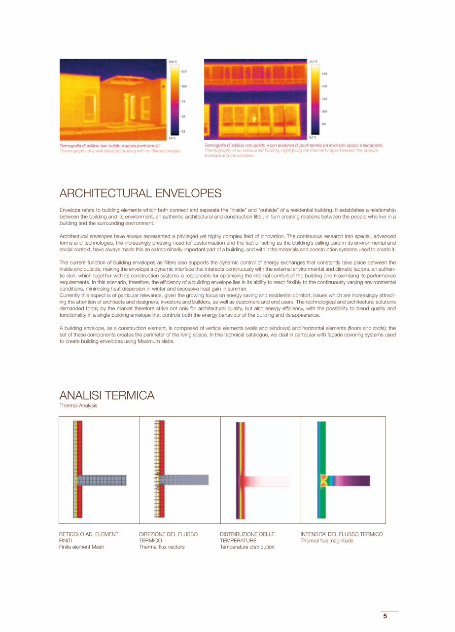
Termografia di edificio non isolato e con evidenza di ponti termici tra involucro opaco e serramenti.Thermography of an uninsulated building, highlighting the thermal bridges between the opaque envelope and the windows.
Termografia di edificio ben isolato e senza ponti termici.Thermography of a well-insulated building with no thermal bridges.
Envelope refers to building elements which both connect and separate the “inside” and “outside” of a residential building. It establishes a relationship between the building and its environment, an authentic architectural and construction filter, in turn creating relations between the people who live in a building and the surrounding environment.
Architectural envelopes have always represented a privileged yet highly complex field of innovation. The continuous research into special, advanced forms and technologies, the increasingly pressing need for customisation and the fact of acting as the building’s calling card in its environmental and social context, have always made this an extraordinarily important part of a building, and with it the materials and construction systems used to create it.
The current function of building envelopes as filters also supports the dynamic control of energy exchanges that constantly take place between the inside and outside, making the envelope a dynamic interface that interacts continuously with the external environmental and climatic factors, an authen-tic skin, which together with its construction systems is responsible for optimising the internal comfort of the building and maximising its performance requirements. In this scenario, therefore, the efficiency of a building envelope lies in its ability to react flexibly to the continuously varying environmental conditions, minimising heat dispersion in winter and excessive heat gain in summer.Currently this aspect is of particular relevance, given the growing focus on energy saving and residential comfort, issues which are increasingly attract-ing the attention of architects and designers, investors and builders, as well as customers and end users. The technological and architectural solutions demanded today by the market therefore strive not only for architectural quality, but also energy efficiency, with the possibility to blend quality and functionality in a single building envelope that controls both the energy behaviour of the building and its appearance.
A building envelope, as a construction element, is composed of vertical elements (walls and windows) and horizontal elements (floors and roofs): the set of these components creates the perimeter of the living space. In this technical catalogue, we deal in particular with façade covering systems used to create building envelopes using Maximum slabs.
ARCHITECTURAL ENVELOPES
RETICOLO AD ELEMENTI FINITIFinite element Mesh
DIREZIONE DEL FLUSSO TERMICOThermal flux vectors
DISTRIBUZIONE DELLE TEMPERATURETemperature distribution
INTENSITA’ DEL FLUSSO TERMICOThermal flux magnitude
ANALISI TERMICAThermal Analysis

6

7
a. Sistema Safety Clip Posa tradizionale a colla con gancio a scomparsa. La posa a parete di lastre Maximum direttamente sulla muratura esistente con sistemi a colla prevede la stesura, sul 100% del fondo di posa, di idoneo collante scelto in base a:- Fondo di posa, supporto su cui applicare la lastra con adeguate caratteristiche di resistenza- Caratteristiche di adesione e strappo- Formato del materiale- Composizione della facciata- Condizioni climatiche e ambientali
b. Sistema a Cappotto La posa di lastre Maximum su un sistema di isolamento a cappotto, ai fini dell’ottenimento di un adeguato comfort termico degli edifici, avviene mediante realizzazione in opera di uno specifico sistema che necessita di un supporto meccanicamente resistente, composto da strati giustapposti alla muratura:- Intonaco- Isolante- Intonaco armato- Lastra in gres porcellanato
c. Sistema Micro Il sistema Micro è un sistema di incollaggio per il montaggio di lastre in gres porcellanato in facciata. Esso è composto da un adesivo permanente ad alta elasticità e da un nastro di montaggio biadesivo, previo trattamento preliminare del sottofondo, che insieme fissano la lastra in facciata in maniera invisibile. Il sistema prevede l’impiego di una sottostruttura metallica che, addossata alla parete da rivestire o eventualmente sopra l’isolante posto a cappotto, determina una retroventilazione dei pannelli.
d. Facciata Ventilata La facciata ventilata è un sistema che permette il rivestimento di un edificio mediante assemblaggio tra l’elemento di rivestimento (lastre Maximum) e elementi portanti in alluminio, mediante giunti strutturali eseguiti in stabilimento. Sono state messe a punto due sottofamiglie di sistemi, con in comune l’assemblaggio struttura/lastra tramite giunto strutturale, diverse nella tipologia di struttura che consente di ancorare Maximum alla parete dell’edificio:
- GHC Maxi Frame: che utilizza un telaio perimetrale autoportante che viene appeso a staffe modulari ancorate alla parete.
- GHL Maxi Light: che usa profili di raccordo verticali sagomati per essere fissati a un tradizionale reticolo di montanti e traversi prefissato alla parete.
TIPOLOGIE DI APPLICAZIONE LASTRE MAXIMUM A PARETE
Per l’applicazione delle lastre Maxi a parete sono disponibili una serie di sistemi di applicazione che possono essere suddivisi in due famiglie:
INVOLUCRO A UMIDO:
INVOLUCRO A SECCO:

8

9
TYPES OF WALL APPLICATION FOR MAXIMUM SLABS
A series of application systems are available for assembling Maxi slabs on walls. These can be divided into two families:
a. Safety Clip system Dry application of Maximum slabs directly onto the existing wall by gluing, a layer of suitable glue is spread over 100% of the laying surface, chosen according to:- Laying base, support on which the slab is applied, with suitably resistant features.- Adhesion and tearing strength- Material size- Façade composition- Climatic and environmental conditions
b. Thermal cladding system Maximum slabs are laid on a thermal cladding system to ensure appropriate thermal comfort inside the building, through the application of a specific system requiring a mechanically resistant support made of a series of layers applied to the brickwork:- Plaster- Insulating layer- Reinforced plaster- Porcelain stoneware slab
c. Micro system The Micro system uses an adhesive to apply the porcelain stoneware slabs to the building façade. It comprises a permanent, highly elastic adhesive and a double-sided adhesive assembly tape; the base support is firstly treated and then the slab is fixed to the façade with this invisible system. The system includes a metal under-frame fitted to the wall or on top of the thermal cladding, which ensures the ventilation behind the panels.
d. Ventilated façade The ventilated façade system involves the assembly of the covering elements (Maximum slabs) onto aluminium load-bearing elements using factory-mounted structural joints. Two sub-families of this system have been developed. While they share the frame-slab assembly using structural joints, they have different types of structures to anchor the Maximum slabs to the wall:
- GHC Maxi Frame: which uses a load-bearing perimeter frame hung on modular brackets anchored to the wall.
- GHL Maxi Light: a system of vertical shaped profiles fixed to a traditional grid of uprights and cross-beams fixed to the wall.
WET ENVELOPES:
DRY ENVELOPES:

10
SISTEMA SAFETY CLIPPosa tradizionale a colla con gancio a scomparsa
La posa a colla di lastre in gres porcellanato sottile e di grandi dimensioni avviene mediante stesura, sul fondo di posa, di un collante appositamente scelto in
base al fondo stesso di posa, al formato del materiale, alla composizione della facciata e alle condizioni climatiche e ambientali.
L’applicazione della colla, che avviene mediante spatola dentata in uno spessore che va da 5 a 10 mm, necessita di una superficie planare e senza onde, a
causa della limitata capacità dell’adesivo di compensare eventuali irregolarità di sottofondo. In funzione del singolo progetto da realizzare, saranno previsti, in
fase di progettazione, idonei giunti strutturali e di frazionamento.
Per aumentare la sicurezza del sistema e per applicazioni su altezze superiori a 2,4 metri, si predispone un gancio di sicurezza in acciaio inox, montato sul retro
della lastra (previa incisione meccanica della stessa) e a filo con la sua superficie, meccanicamente agganciato alla muratura.
Tutte le lavorazioni sulla lastra, per garantire la massima qualità e tenuta, sono eseguite esclusivamente in fabbrica.
SISTEMA BREVETTATO / INVOLUCRO A UMIDO
2
3
1
4
dettaglio orizzontale - horizontal detail
300 cm

11
1. SAFETY CLIP (gancio sicurezza a scomparsa) (Concealed safety hook)
2. LASTRA MAXIMUM Maximum Slabs
3. COLLANTE Glue
4. MURATURA PORTANTE ED INTONACO Load-bearing wall and laster
1
2
3
4
dettaglio verticale - vertical detail
A glue, chosen specifically to suit the laying surface, the material size, the façade composition and the climatic and environmental conditions, is spread on the
laying surface to support the large-sized, thin porcelains stoneware slabs.
The glue, applied using a toothed spatula with a thickness of 5 to 10 mm, requires a flat, smooth surface, as it has a limited capacity to compensate any un-
evenness in the underlying surface. Depending on the specific project, suitable structural joints and expansion joints are included in the design.
To increase the safety of the system and for applications on heights above 2.4 metres, a stainless steel safety hook is fitted to the back of the slab (using a
mechanical incision), which is in turn hooked mechanically onto the building, flush to the wall.
To ensure maximum quality and resistance, the slab processing is performed exclusively at the factory.
SAFETY CLIP SYSTEMConventional glue-mounting system with concealed hooks
PATENTED SYSTEM / WET ENVELOPES
NOTE: Il fissaggio meccanico previsto per la “Safety Clip” viene scelto tra diverse tipologie in funzione del materiale di cui è composto il supporto murario.
The mechanical fixing for the “Safety Clip” is chosen from different types according to the material comprising the masonry support.

12
EVENTS GALLERY – BALOCCO CIRCUIT, ITALY
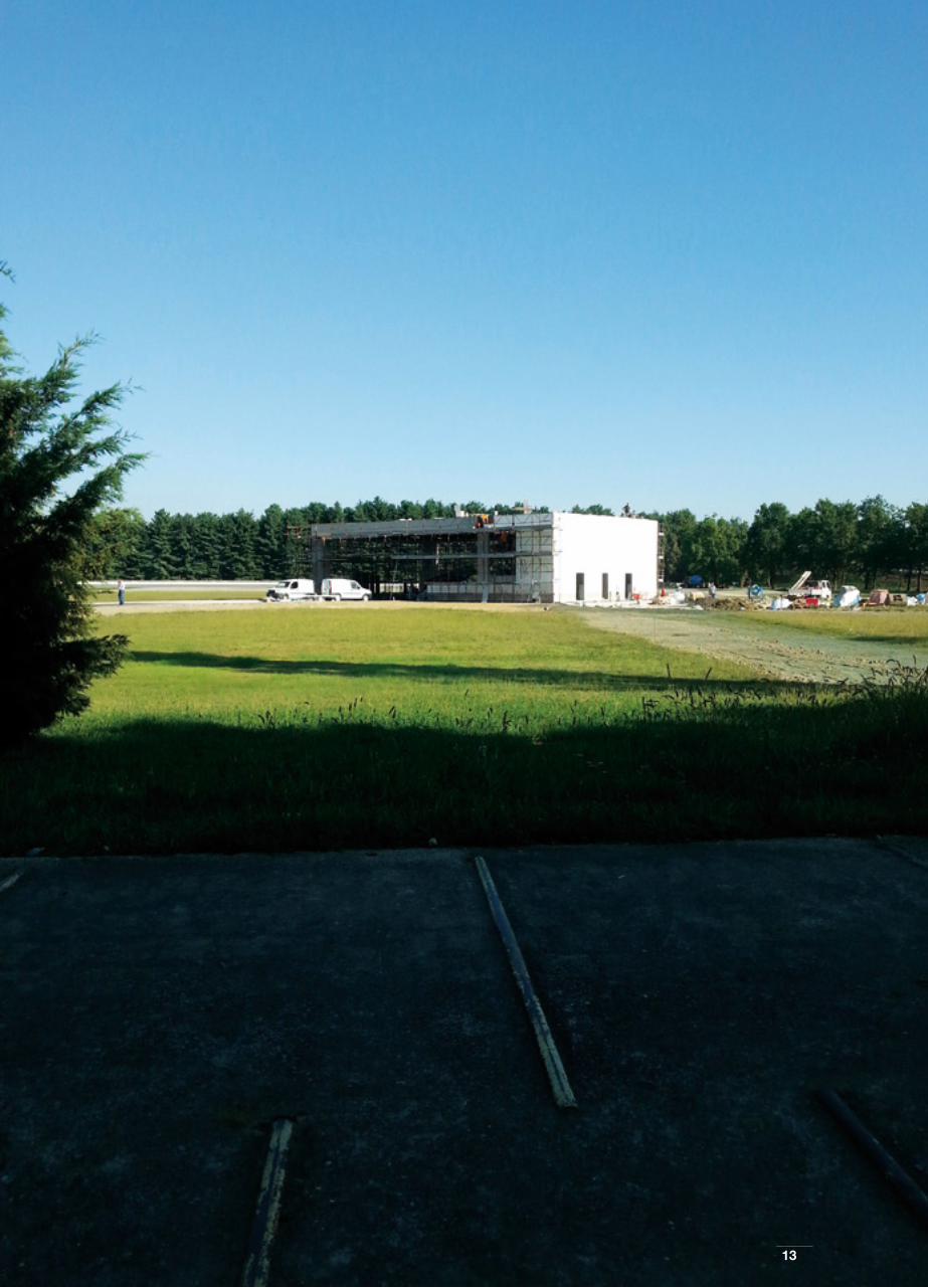
1313

14
UTILIZZO SAFETY CLIPSafety Clip use
La tecnologia dell’incollaggio tradizionale può essere applicato per qualsiasi dimensione di lastra, ma per applicazioni oltre i 2,4 metri si consiglia
l’utilizzo del ritegno di sicurezza.
L’applicazione delle lastre in gres porcellanato direttamente sul supporto murario rende il sistema adatto per involucri esterni in cui non è necessaria o
richiesta alcuna performance energetica dell’involucro, oppure laddove il supporto murario sia già adeguatamente isolato.
Nello schema sottostante si propone un range dimensionale e alcune indicazioni principali sull’incollaggio di lastre Maximum in rivestimento esterno in
funzione del posizionamento delle stesse in facciata.
Conventional gluing technologies can be used with any size of slab, but for applications above 2.4 metres it is advisable to use safety retainers.
The application of the porcelain stoneware slabs directly onto the brickwork makes the system suited for envelopes that do not require high-energy
performance, or where the walls are already suitably insulated.
The diagram below describes the size ranges and some key indications for gluing Maximum slabs on outer walls depending on their position on the
façade.
PATENTED SYSTEM

15
RIVESTIMENTO SAFETY CLIP RANGE DIMENSIONALE E UTILIZZOSafety clip covering size range and use
PATENTED SYSTEM
NOTE: Si ricorda che il range dimensionale è puramente indicativo, poiché è possibile realizzare rivestimenti in esterno con lastre di tutte le dimensioni, fino al formato pieno (300x150 cm). - The size range is purely indicative, as external coverings can be produced using slabs of all sizes (up to 300x150 cm).
La legenda si riferisce all’altezza fuoriterra dell’edificio - The key refers to the height above ground of the building
h. 20 MT
h. 6 MT
h. 3 MT
750 1000 1200 1500 1800 2250 3000
750
1000
1200
1500
1800
2250
3000

16
SISTEMA A CAPPOTTO
Il sistema di rivestimento a cappotto ha raggiunto negli ultimi anni una notevole diffusione in Europa grazie alle crescenti e cogenti necessità di garantire un
adeguato comfort termico degli edifici, sia di nuova costruzione che in ristrutturazione. L’isolamento dell’involucro edilizio è, infatti, il primo passo per il con-
tenimento dei flussi energetici e la riduzione del fabbisogno energetico negli edifici, e si traduce in un miglior comfort per gli utenti e un risparmio economico
dettato dal minor consumo di energia necessaria per riscaldare e raffrescare gli ambienti.
Il sistema per realizzare un cappotto termico con lastre Maximum mutua la stratigrafia del tradizionale sistema a cappotto con finitura minerale, ma rispetto ad
essa conferisce un valore aggiunto determinato dalla finitura in lastre di gres porcellanato sottile.
Il sistema a cappotto permette infatti la posa, sullo strato di isolamento termico (il cui spessore deve essere deciso sulla base dei calcoli di progetto) di lastre
in gres porcellanato dello spessore di 6 mm.
Il sistema proposto richiede un supporto meccanicamente resistente, per ottenere il quale è stato studiato un sistema di rivestimento e posa su pannelli isolanti
in EPS o XPS (rispettivamente polistirene espanso o polistirene espanso estruso) caratterizzato da elevate resistenze meccaniche (a trazione e compressione)
e basso modulo elastico, in grado di sostenere il peso e le sollecitazioni generate dai rivestimenti e dalle dilatazioni termiche.
L’isolante deve avere una superficie ruvida per favorire l’aggrappaggio del rivestimento e profili squadrati e privi di battente, e spessore ricavato dal calcolo di
progetto. Per quanto riguarda le lastre di rivestimento sono da prediligere colori chiari, che abbiano un indice di riflessione superiore al 20%.
Ciò premesso, occorre sottolineare come il raggiungimento dei risultati attesi in termini di isolamento termico e di durabilità del rivestimento è strettamente cor-
relato alla accurata e corretta progettazione dei particolari costruttivi del sistema in tutti i punti in cui si potrebbe venire a creare un ponte termico e alla corretta
realizzazione delle opere.
1
2
3
4
5
6
7
8
INVOLUCRO A UMIDO

17
1. LASTRA MAXIMUM Maximum slab
2. COLLANTE Glue
3. INTONACO ARMATO4. Reinforced plaster5.
6. ISOLANTE Insulating layer
7. INTONACO E COLLANTE Plaster and glue
8. MURATURA PORTANTE Load-bearing wall
1
2
3,4,5
6
7
8
dettaglio verticale - vertical detail
THERMAL CLADDING SYSTEM
WET ENVELOPES
In the past few years, thermal cladding has become increasingly widespread in Europe due to the growing statutory and technical requirements to ensure heat
comfort in both new builds and renovations. The insulation of any building envelope is the first step to ensuring the reduction in energy flows and consumption
in any building, and translates into improved comfort for users and financial savings due to lower energy consumption to heat and cool the inside.
The thermal cladding system using Maximum slabs changes the outer layer of conventional cladding systems which have mineral finishes, but adds greater
value with the finishing layer in thin porcelain stoneware slabs.
The thermal cladding system involves the laying of a 6 mm thick porcelain stoneware slab on top of a heat insulating layer (the thickness of which is decided
according to design calculations).
The proposed system requires a mechanically resistant support, designed using a covering and laying system on EPS or XPS (respectively, expanded poly-
styrene or extruded polystyrene) insulating panels with high mechanical resistance (to traction and compression) and low elastic modulus, able to support the
weight and stress generated by the coverings and by thermal expansion.
The insulating layer must have a rough surface in order to allow the covering to grip, with square profiles and no ledges, of a thickness established in the design
calculations. For covering slabs, pale colours with a reflective index of greater than 20% should be chosen.
Having said this, it should be underlined that the achievement of expected results in terms of heat insulation and durability of the outer covers is closely related
to the careful and correct design of the construction details of the system, in all points which could create a thermal bridge, as well as the correct installation
of the system.

18
PRIVATE HOUSING - PESARO, ITALY
18

1919

20
SEQUENZA DI POSA SISTEMA A CAPPOTTOCladding System laying sequence
AL FINE DI UNA CORRETTA REALIZZAZIONE DEL SISTEMA A CAPPOTTO, OCCORRE SEGUIRE ALCUNI ACCORGIMENTI:
1. La posa dovrà essere eseguita con il metodo della doppia spalmatura, stendendo l’adesivo sia sul sottofondo che sul retro della lastra, per garantire
l’assenza di vuoti all’interfaccia rivestimento/supporto, dove l’acqua piovana, infiltrandosi, potrebbe ristagnare creando (in caso di gelo) tensioni che
potrebbero provocare il distacco del rivestimento. Inoltre, in questo modo si ripartiscono in modo uniforme e su una superficie più ampia le tensioni
che si avranno a seguito dei movimenti differenziali tra rivestimento e supporto, dovuti ad esempio a variazioni termiche, e per evitare fenomeni di
efflorescenze in facciata.
2. La posa deve essere effettuata a fuga larga, con larghezza correlata al formato delle lastre e alle condizioni climatiche locali.
3. Occorre rispettare i giunti strutturali, sia per quanto riguarda dimensione che posizione. Si dovranno inoltre prevedere giunti di frazionamento in
corrispondenza di fasce marcapiano, angoli e spigoli (e in ogni caso ogni 9-12 mq)
4. Occorre proteggere il rivestimento dalla penetrazione di acqua e potenziali danni da cicli di gelo-disgelo mediante applicazione di adeguate sigillature
o scossaline metalliche nella parte superiore e inferiore dell’intero rivestimento, e in corrispondenza di finestre e aperture.
THE FOLLOWING RECOMMENDATIONS HELP TO ENSURE THE CORRECT INSTALLATION OF THE CLADDING SYSTEM:
1. The system should be laid using the double glue spreading method, spreading the glue on both the underlying surface and the back of the slab, to
prevent voids between the covering and the support, where rainwater could filter in and (in the event of frost) create stress which could cause the
slab to become detached. Moreover, this method ensures that the stress caused by the differential movements between the slabs and the support
surface, due for example to variations in temperature, is spread more evenly, thus preventing efflorescence on the façade.
2. The slabs must be laid with wide gaps to suit the slab size and the local climatic conditions.
3. Structural joints must be fitted to suit both slab size and position. Expansion joints must also be inserted along string courses, corners and ridges
(and in any case every 9-12 m2)
4. The covering must be protected against water infiltration and potential damage from freezing-melting by fitting suitable seals or metal flashing on the
top and bottom of the whole covering, as well as around doors and windows.
INVOLUCRO A UMIDO / WET ENVELOPES

2121

22
UTILIZZO SISTEMA CAPPOTTO Thermal Cladding System use
INVOLUCRO A UMIDO / WET ENVELOPES
Il Sistema a Cappotto viene utilizzato in tutti gli interventi di nuova costruzione o ristrutturazione in cui si ha necessità di isolare termicamente
l’involucro edilizio e di raggiungere i necessari valori di legge di trasmittanza dei componenti verticali di involucro o di fabbisogno energetico di
energia per il funzionamento dell’edificio.
Si sottolinea il fatto che, in caso di nuova costruzione o di ristrutturazione ingente di un immobile, sussiste l’obbligo di rispettare i requisiti prestazionali
sopra indicati e che sono attualmente in vigore alcune misure incentivanti l’efficientamento energetico degli edifici mediante detrazioni fiscali (in cui
può rientrare il sistema a cappotto).
Nello schema sottostante si propone un range dimensionale e alcune indicazioni principali sull’incollaggio di lastre Maximum in rivestimento a
cappotto esterno.
Si ricorda che il range dimensionale è puramente indicativo, poiché è possibile realizzare rivestimenti in esterno con lastre Maximum di tutte le
dimensioni, fino al formato 150x150 cm.
The Cladding System is used in all new builds and renovations where the building envelope has to be insulated, and to meet statutory requirements
concerning the transmittance of vertical components and energy needs linked to the building.
It should be underlined that in the case of new builds or large-scale renovations, the above-indicated performance requirements are obligatory and
that incentives in the form of tax deductions may be available for energy efficiency measures (including thermal cladding systems).
The diagram below describes the size ranges and some key indications for gluing Maximum slabs on outer walls with thermal cladding.
The size range is purely indicative, as external coverings can be produced using Maximum slabs of all sizes (up to 150x150 cm).

23
RIVESTIMENTO A CAPPOTTO RANGE DIMENSIONALE E UTILIZZOCovering with Thermal Cladding size range and use
INVOLUCRO A UMIDO / WET ENVELOPES
750 1000 1200 1500 1800 2250 3000
750
1000
1200
1500
1800
2250
3000
375
IL SISTEMA COMPRENDE: THE SYSTEM INCLUDES:
Isolamente a cappotto tipo XPS o EPSThermal cladding, type XPS or EPS
Pacchetto finitura cappottoCladding finishing system
h. 20 MT
NOTE: Si ricorda che il range dimensionale è puramente indicativo, poiché è possibile realizzare rivestimenti in esterno con lastre di tutte le dimensioni, fino al formato pieno (150x150 cm). - The size range is purely indicative, as external coverings can be produced using slabs of all sizes (up to 150x150 cm).
La legenda si riferisce all’altezza fuoriterra dell’edificio - The key refers to the height above ground of the building.
XPS: Polistirene estruso - Extruded polystyreneEPS: Polistirene ESPANSO SINTERIZZATO - Sintered expanded polystyrene
24
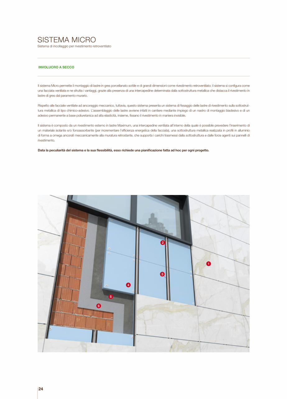
SISTEMA MICROSistema di incollaggio per rivestimento retroventilato
Il sistema Micro permette il montaggio di lastre in gres porcellanato sottile e di grandi dimensioni come rivestimento retroventilato; il sistema si configura come
una facciata ventilata e ne sfrutta i vantaggi, grazie alla presenza di una intercapedine determinata dalla sottostruttura metallica che distacca il rivestimento in
lastre di gres dal paramento murario.
Rispetto alle facciate ventilate ad ancoraggio meccanico, tuttavia, questo sistema presenta un sistema di fissaggio delle lastre di rivestimento sulla sottostrut-
tura metallica di tipo chimico-adesivo. L’assemblaggio delle lastre avviene infatti in cantiere mediante impiego di un nastro di montaggio biadesivo e di un
adesivo permanente a base poliuretanica ad alta elasticità, insieme, fissano il rivestimento in maniera invisibile.
Il sistema è composto da un rivestimento esterno in lastre Maximum, una intercapedine ventilata all’interno della quale è possibile prevedere l’inserimento di
un materiale isolante e/o fonoassorbente (per incrementare l’efficienza energetica della facciata), una sottostruttura metallica realizzata in profili in alluminio
di forma a omega ancorati meccanicamente alla muratura retrostante, che supporta i carichi trasmessi dalla sottostruttura e dalle forze agenti sui pannelli di
rivestimento.
Data la peculiarità del sistema e la sua flessibilità, esso richiede una pianificazione fatta ad hoc per ogni progetto.
1
2
3
4
5
6
INVOLUCRO A SECCO

25
150 cm
1. LASTRA MAXIMUM Maximum slab
2. STRUTTURA IN ALLUMINIO Aluminium frame
3. NASTRO BIADESIVO + ADESIVO STRUTTURALE Double sided fixing tape + structural adhesive
4. ISOLANTE Insulating layer
5. INTONACO E COLLANTE6. Plaster and glue 7. MURATURA PORTANTE Load-bearing wall
MICRO SYSTEMAdhesive system for rear-ventilated coverings
The Micro system involves the assembly of thin porcelain stoneware slabs onto a rear-ventilated covering; it belongs to the family of ventilated façades due to
the cavity wall which is created using a metal sub-frame that keeps the porcelain stoneware covering at a distance from the wall facing.
Compared to ventilated façades with mechanical anchoring, however, this system uses a chemical-adhesive metal sub-frame to fix the slabs. The slabs are
assembled using a highly elastic permanent adhesive and a double-sided adhesive assembly tape which, together, fix the covering invisibly to the wall.
The Micro System is composed of an external cladding made by Maximum slabs, a ventilated cavity, within which a thermal and/or acoustic insulation layer
can be placed (in order to improve the facade energy efficiency), a metallic substructure, made by aluminum omega profiles mechanically anchored to the wall,
which supports the loads transmitted by the substructure and the forces acting on the cladding panels.
Given the flexibility and special features of this system, it has to be designed specifically on a case-by-case basis.
DRY ENVELOPES
dettaglio orizzontale - horizontal detail
150 cm
26
LAMBORGHINI HEADQUARTERS - SANT’AGATA BOLOGNESE - BOLOGNA, ITALY
26

2727

28
29
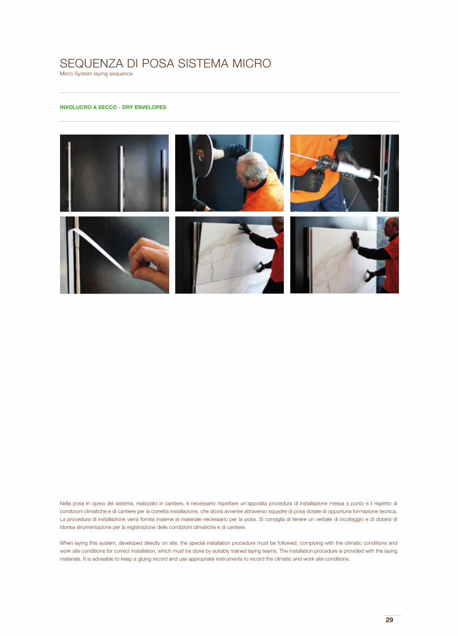
SEQUENZA DI POSA SISTEMA MICROMicro System laying sequence
Nella posa in opera del sistema, realizzato in cantiere, è necessario rispettare un’apposita procedura di installazione messa a punto e il rispetto di
condizioni climatiche e di cantiere per la corretta installazione, che dovrà avvenire attraverso squadre di posa dotate di opportuna formazione tecnica.
La procedura di installazione verrà fornita insieme al materiale necessario per la posa. Si consiglia di tenere un verbale di incollaggio e di dotarsi di
idonea strumentazione per la registrazione delle condizioni climatiche e di cantiere.
When laying this system, developed directly on site, the special installation procedure must be followed, complying with the climatic conditions and
work site conditions for correct installation, which must be done by suitably trained laying teams. The installation procedure is provided with the laying
materials. It is advisable to keep a gluing record and use appropriate instruments to record the climatic and work site conditions.
INVOLUCRO A SECCO - DRY ENVELOPES

30
Il sistema Micro può essere utilizzato in tutti gli interventi di nuova costruzione o ristrutturazione, fino a un massimo di 20 metri circa di altezza.
La possibilità di inserire nel pacchetto di facciata uno strato di isolante rende il sistema performante anche dal punto di vista energetico, utilizzabile
quindi in interventi in cui si ha necessità di isolare termicamente l’involucro edilizio e di raggiungere determinati valori di trasmittanza dei componenti
verticali di involucro o di fabbisogno energetico di energia per il funzionamento dell’edificio.
Si sottolinea il fatto che, in caso di nuova costruzione o di ristrutturazione ingente di un immobile, sussiste l’obbligatorietà di rispettare i requisiti prestazionali
sopra indicati e che sono attualmente in vigore alcune misure incentivanti all’efficientamento energetico degli edifici mediante detrazioni fiscali.
Nello schema sottostante si propone un range dimensionale e alcune indicazioni principali sull’incollaggio di lastre Maximum in rivestimento esterno
in funzione del posizionamento delle stesse in facciata. Si ricorda che il range dimensionale è puramente indicativo, poiché è possibile realizzare
rivestimenti in esterno con lastre di tutte le dimensioni, fino al formato pieno (300x150 cm).
The Micro system can be used in any new build or renovation, up to a maximum height of 20 metres.
The possibility to include an insulating layer in the façade increases the energy performance of the system, so it can also be used in projects that
require the heat insulation of the building envelope in order to achieve certain transmittance values of the vertical envelope components and meet the
building’s energy requirements.
It should be underlined that in the case of new builds or large-scale renovations, the above-indicated performance requirements are obligatory and that
incentives in the form of tax deductions may be available for energy efficiency measures.
The diagram below describes the size ranges and some key indications for gluing Maximum slabs on outer walls depending on their position on the
façade. The size range is purely indicative, as external coverings can be produced using slabs of all sizes (up to 300x150 cm).
UTILIZZO SISTEMA MICROMicro System use
INVOLUCRO A SECCO - DRY ENVELOPES

31
RIVESTIMENTO MICRO RANGE DIMENSIONALE E UTILIZZOMicro covering system size range and use
INVOLUCRO A SECCO - DRY ENVELOPES
750 1000 1200 1500 1800 2250 3000
750
1000
1200
1500
1800
2250
3000 h. 20 MT
NOTE: Si ricorda che il range dimensionale è puramente indicativo, poiché è possibile realizzare rivestimenti in esterno con lastre di tutte le dimensioni, fino al formato pieno (300x150 cm). - The size range is purely indicative, as external coverings can be produced using slabs of all sizes (up to 300x150 cm).
La legenda si riferisce all’altezza fuoriterra dell’edificio - The key refers to the height above ground of the building.
XPS: Polistirene estruso - Extruded polystyreneEPS: Polistirene espanso sinterizzato - Sintered expanded polystyrene
IL SISTEMA COMPRENDE - THE SYSTEM INCLUDES
- Isolamente a cappotto tipo XPS o EPS Thermal cladding, type XPS or EPS
- Retinatura sul retro lastra Maximum Meshing on the rear of the Maximum slab
- Sottostruttura Sub-frame
- Fissaggio specifico sulla base del tipo di muratura e di isolante previsto Specific fixing according to the size and type of insulation
- Collante sistema Micro Micro system glue
h. 6 MT

32
FACCIATA VENTILATAVentilated façade
Grazie ai sistemi di facciata ventilata, Maximum rimane “Maxi” anche per questi sistemi tecnologici di involucro: è possibile infatti rivestire qualsiasi edificio, sia
esso modulare e che fa della ripetitività dei moduli la propria peculiarità (caratteristica vincente per l’utilizzo di formati “pieni” quali il 300x150-120-100 cm), che
non modulare e quindi richiedente elementi multipli, ma differenziati in dimensione e forme.
L’applicazione delle lastre in facciata ventilata utilizza la tecnologia dell’assemblaggio tra elemento di rivestimento ed elementi portanti in alluminio mediante
giunti strutturali realizzati in stabilimento, seguendo una rigorosa e meticolosa procedura.
Lo studio pre-progetto, l’adeguamento degli standard del sistema al singolo edificio, unitamente al controllo sistematico dei materiali e delle superfici di
aggrappaggio del giunto strutturale, consentono infatti di sfruttare appieno le proprietà complementari di Maximum e della struttura in alluminio, ma soprattutto
di eliminare dal cantiere qualsiasi operazione che non sia un semplice ancoraggio meccanico: Maximum per i sistemi di rivestimento, si presenta quindi
preparata ad essere “semplicemente” agganciata e serrata in cantiere alla muratura esistente, con una garanzia dell’assiemaggio in atmosfera controllata dello
stabilimento di produzione.
Il sistema è stato sviluppato proprio per consentire la massima flessibilità per il progettista utilizzando due sottofamiglie di sistemi, che hanno in comune
l’assemblaggio struttura/lastra tramite giunto strutturale, ma che si differenziano nella tipologia di struttura che consente di ancorare Maximum alla parete
dell’edificio:
- GHC MAXI FRAME, che utilizza un telaio perimetrale autoportante disegnato per essere direttamente appeso a staffe modulari ancorate
alla parete dell’edificio;
- GHL MAXI LIGHT, che utilizza invece profili di raccordo verticali sagomanti per essere fissati ad un tradizionale reticolo montanti e traversi
pre-fissato alla parete.
Using ventilated façades, Maximum is “Maxi” even for these technological envelopes: the system can be used to cover any kind of building, whether modular
- and here the repetition of the modules is its speciality (a winning feature for the use of “full” sizes, e.g. 300x150-120-100 cm), and non-modular systems,
requiring multiple elements in different shapes and sizes.
Slabs are applied to ventilated façades using an assembly technology comprising the covering slabs and aluminium load-bearing structural joints produced in
the factory, based on a strict, meticulous procedure.
The pre-design study, adaptation of the system standards to each building project, and the systematic checking of the materials and structural joint gripping
surfaces, all help to fully exploit the complementary properties of Maximum and the aluminium frame, as well as eliminating all site operations apart from simple
mechanical anchoring: Maximum for covering systems is therefore ready to be “simply” hooked and tightened to the existing wall on site, with the guarantee
of assembly in the controlled atmosphere of the production site.
The system was designed specifically to offer excellent flexibility for designers using two sub-families of systems, which share the frame-slab assembly using
a structural joint, but which differ in the type of frame used to anchor Maximum to the wall of the building:
- GHC MAXI FRAME, which uses a load-bearing perimeter frame designed to be hung directly on modular brackets anchored to the wall;
- GHL MAXI LIGHT, which on the other hand uses vertical shaped profiles fixed to a traditional grid of uprights and cross-beams fixed to
the wall.
INVOLUCRO A SECCO - DRY ENVELOPES

33
GHC MAXI FRAME SYSTEM
FACCIATA VENTILATAVentilated façade
GHL MAXI LIGHT SYSTEM

34
UTILIZZO FACCIATA VENTILATA
La facciata ventilata assemblata a secco può essere utilizzata sia nelle nuove costruzioni che in ristrutturazioni.
La sua composizione stratigrafica permette l’installazione all’interno dell’intercapedine ventilata di uno strato di isolante, ottimizzando così anche le
prestazioni energetiche dell’involucro così realizzato e riducendo le dispersioni attraverso le pareti, rendendo il sistema utilizzabile quindi in interventi in
cui si ha necessità di isolare termicamente l’involucro edilizio e di raggiungere determinati valori di trasmittanza dei componenti verticali di involucro o
di fabbisogno energetico di energia per il funzionamento dell’edificio.
La scelta per definire quale dei due sistemi sia il più appropriato all’edificio da rivestire risulta essere in funzione di vari parametri:
- Magnitudine del progetto - Modularità del disegno di facciata - Dimensione del modulo - Ripetitività del modulo
- Altezza dell’edificio - Forometria di finestre - Presenza di aggetti e balconi - Quantità di elementi speciali
- Organizzazione e logistica di cantiere
I due sistemi sono comunque in grado di soddisfare le necessità di qualsiasi edificio, mantenendo altresì un altissimo valore di resistenza ai carichi di
vento, in linea con i valori raggiunti dai migliori rivestimenti ventilati tradizionali con lastre ceramiche. Nei sistemi Maxi Ventilata infatti, le lastre continuano
ad avere mera funzione di elemento “portato”, lasciando alle strutture di alluminio il compito di sopportare i carichi, limitare le flessioni degli elementi e
di trasferire quindi detti carichi alla struttura muraria: l’appropriato studio del posizionamento degli elementi di alluminio e dei giunti strutturali, eseguito
per singolo progetto, consente di dissipare carichi eccessivi per la lastra e garantirne quindi l’integrità e la longevità. L’opportunità di scegliere tra due
sistemi suggerisce quindi di analizzare in fase preliminare di progetto dell’edificio l’intreccio dei parametri sopraindicati, al fine di massimizzare resa
tecnica ed economica, individuando il sistema più adatto e/o quello più facilmente mediabile. Nella progettazione preliminare del rivestimento si dovrà
ovviamente considerare che, se il “cucire addosso all’edificio una pelle” genererà dei tagli sartoriali del tessuto (alias ceramica), tali sfridi andranno a gra-
vare sull’onere della realizzazione. Identificare una complementarietà tra le dimensioni del modulo Maximum e quelle dell’edificio da rivestire permette
di conseguenza di ottimizzare la realizzazione: in un edificio di nuova costruzione ciò può avvenire coordinando la progettazione, mentre in caso di
ristrutturazione di un edificio esistente l’adeguarsi alle dimensioni e alle caratteristiche architettoniche di quanto già realizzato potrebbe rendere oneroso
l’utilizzo del GHC Maxi Frame a vantaggio della maggior flessibilità GHL Maxi Light.
GHC Maxi Frame e GHL Maxi Light sono ovviamente compatibili: ciò consente, in funzione dell’edificio o del progetto, di utilizzare eventualmente
entrambi i sistemi, differenziandone l’utilizzo in zone omogenee: ovviamente Frame per le zone a modulo costante, Light per i sottomultipli ed elementi
speciali.
Il dimensionamento delle fughe tra le singole lastre Maximum dovrà essere accuratamente determinato per consentire la dilatazione termica degli ele-
menti ed evitare che gli stessi sottopongano la lastra ceramica a carichi non appropriati. La dilatazione termica è un fenomeno naturale, tipico di ciascun
materiale ed è il funzione della lunghezza dell’elemento in considerazione: più un elemento è lungo, maggiore sarà a livello assoluto il suo allungamento.
Entrambi i sistemi, seppur con valenze economiche diverse posso essere dotati di:
- Rete di sicurezza capace di limitare la caduta di frammenti di lastra frantumata per impatto anomalo;
- Ritegno meccanico continuo, bilaterale o puntuale;
- Chiusura delle fughe tra le lastre (sistema Frame) onde creare una prima barriera all’acqua, capace di limitare la quantità della stessa all’interno
dell’intercapedine ventilata.
INVOLUCRO A SECCO - DRY ENVELOPES

35
VENTILATED FAÇADE USE
The dry assembled ventilated façade can be used in both new builds and renovations.
The layered composition allows it to be installed in ventilated cavity walls with an insulating layer, also optimising the energy performance of the enve-
lope and reducing dispersion through the walls, so it can also be used in projects that require the heat insulation of the building envelope in order to
achieve certain transmittance values of the vertical envelope components and meet the building’s energy requirements.
The choice of the most appropriate of the two systems for the building works in hand depending on several parameters:
- Size of the project - Modularity of the façade - Size of the modules - Repetition of the modules
- Building height - Size and number of windows - Presence of protrusions and balconies - Number of special elements
- Site organisation and logistics
The two systems are in any case able to meet the needs of any building, also maintaining high resistance to wind loads, in line with the values achieved
by the best traditional ventilated covering systems using ceramic slabs.
In the Maxi Ventilated systems, the slabs continue to have a merely “supported” function, while the aluminium frame supports the loads, limiting the
bending of the elements and transferring the loads to the wall below: the positioning of the aluminium elements and structural joints is designed specifi-
cally for each project, in order to dissipate any excessive loads on the slab and guarantee integrity and durability. The choice between the two systems
is based on a careful preliminary analysis of the building to measure the above-described parameters, to maximise technical performance and cost-
effectiveness, identifying the most suitable and/or most easily applicable system. The preliminary design of the covering must consider that the idea of
“stitching a skin onto the building” will generate cuts and (in this case ceramic) waste, and such offcuts must be calculated in the cost of the works.
Identifying the complementarity between the size of the Maximum module and that of the building to be covered consequently optimises the design: in
a new build, this can be done at design stage, but when renovating an existing building we have to adapt to the existing sizes and architectural features,
which could make the sue of GHC Maxi Frame more costly, while advantages lay in the greater flexibility of GHL Maxi Light.
GHC Maxi Frame and GHL Maxi Light are of course compatible: depending on the building or the design, both systems can be used, differentiating
their use in uniform areas: obviously, Frame in areas with constant modules, Light for sub-multiples and special elements. The size of the gaps between
the Maximum slabs must be carefully calculated in order to ensure the thermal expansion of the elements and prevent them from creating excessive
loads for the ceramic slabs. Heat expansion is a natural phenomenon, typical of any material, and depends on the length of the element considered:
the longer the element, the greater the expansion in absolute terms.
Although with different costs, both systems can be fitted with:
- Safety mesh to limit the fall of fragments from crushed slabs following abnormal impacts;
- Continuous, two-sided or specific mechanical retainers;
- Closed gaps between the slabs (Frame) to create a water barrier to limit the amount of water inside the ventilated cavity wall.
INVOLUCRO A SECCO - DRY ENVELOPES
36
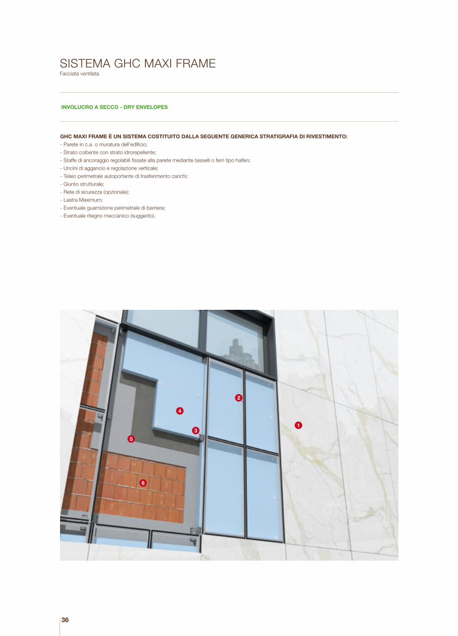
SISTEMA GHC MAXI FRAMEFacciata ventilata
INVOLUCRO A SECCO - DRY ENVELOPES
1
2
3
4
5
6
GHC MAXI FRAME È UN SISTEMA COSTITUITO DALLA SEGUENTE GENERICA STRATIGRAFIA DI RIVESTIMENTO:
- Parete in c.a. o muratura dell’edificio;
- Strato coibente con strato idrorepellente;
- Staffe di ancoraggio regolabili fissate alla parete mediante tasselli o ferri tipo halfen;
- Uncini di aggancio e regolazione verticale;
- Telaio perimetrale autoportante di trasferimento carichi;
- Giunto strutturale;
- Rete di sicurezza (opzionale);
- Lastra Maximum;
- Eventuale guarnizione perimetrale di barriera;
- Eventuale ritegno meccanico (suggerito).

37
dettaglio orizzontale - horizontal detail
GHC MAXI FRAME IS A SYSTEM BASED ON THE FOLLOWING GENERIC LAYERS OF OUTER COVERING:
- Building wall in reinforced concrete or brick;
- Insulation with water-repellent layer;
- Adjustable anchoring brackets fixed to the wall with plugs or Halfen connectors;
- Vertically adjusted hooks;
- Load-bearing perimeter frame for load transfer;
- Structural joint;
- Safety mesh (optional);
- Maximum slab;
- Perimeter seal barrier, where appropriate;
- Mechanical retainer if required (recommended).
GHC MAXI FRAME SYSTEMVentilated façades
INVOLUCRO A SECCO - DRY ENVELOPES
dettaglio verticale - vertical detail
300
cm
1
2
3
4
5
6
1. LASTRA MAXIMUM Maximum slab
2. STRUTTURA IN ALLUMINIO Aluminium frame
3. STAFFE Brackets
4. ISOLANTE Insulating layer
5. INTONACO E COLLANTE Plaster and glue
6. MURATURA PORTANTE Load-bearing wall

38
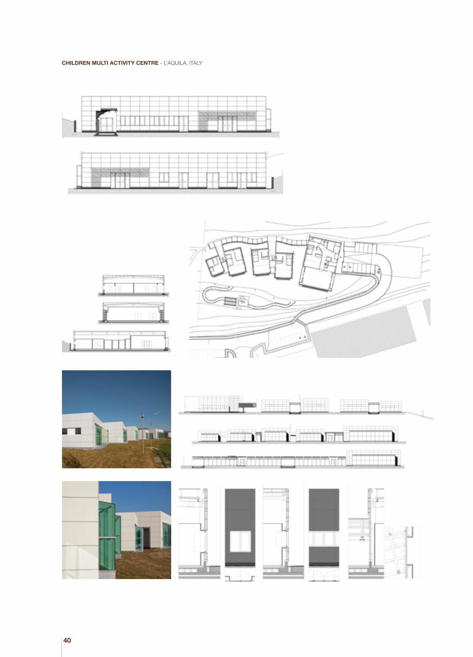
CHILDREN MULTI ACTIVITY CENTRE - L’AQUILA, ITALY
38
3939
40
CHILDREN MULTI ACTIVITY CENTRE - L’AQUILA, ITALY

4141

4242

43
SEQUENZA DI POSA SISTEMA GHC MAXI FRAMEGHC Maxi Frame System laying sequence
INDICATIVAMENTE, GHC MAXI FRAME SARÀ UTILIZZATO PREVALENTEMENTE PER PROGETTI CON ELEVATA MAGNITUDINE,
SISTEMATICA RIPETITIVITÀ DEL MODULO E RILEVANTE ALTEZZA DELL’EDIFICIO.
Una tipica sequenza di installazione può essere schematizzata come segue:
- Predisposizione, sulla muratura da rivestire, degli ancoraggi meccanici (staffe e tasselli o ferri tipo halfen)
- Piombatura e serraggio delle staffe in posizione spaziale
- Posa dell’eventuale strato di coibentazione
- Assiemaggio degli uncini nelle cellule
- Tiro in alto delle cellule
- Ancoraggio meccanico delle cellule alle staffe tramite gli uncini
- Regolazione fine della singola cellula nelle due direzioni spaziali prevalenti
- Ripetizione delle tre fasi precedenti per la cellula successiva
- Chiusura con griglie delle fessure di ventilazione
- Realizzazione di terminali ed imbotti finestre
INDICATIVELY, GHC MAXI FRAME IS USED MAINLY FOR LARGE-SIZED PROJECTS, WITH SYSTEMATIC MODULE REPETITION AND
IMPORTANT BUILDING HEIGHTS.
A typical installation sequence can be described as follows:
- Fitting the mechanical anchorages to the wall (brackets and plugs or Halfen connectors)
- Sealing and tightening the brackets
- Laying the insulating layer, if required
- Fitting hooks into the cells
- Raising the cells
- Mechanically anchoring the cells to the brackets using the hooks
- Finely adjusting each cell in the two main directions
- Repeating the previous three steps for the next cell
- Closing the ventilation gaps with grilles
- Fitting the terminal elements and window intrados
INVOLUCRO A SECCO - DRY ENVELOPES

44
LOGISTICA DI CANTIERE GHC MAXI FRAMEGHC Maxi Frame site logistics
INVOLUCRO A SECCO - DRY ENVELOPES
La logistica di cantiere dovrà prevedere lo stoccaggio per i contenitori dei componenti di facciata, con adeguato spazio circostante per consentire
le manovre di spostamento e di estrazione delle stesse, in funzione dei macchinari che verranno utilizzati per l’accesso alla parete da rivestire, la
movimentazione, e la posa dei componenti di facciata; come esemplificazione si indicano le seguenti famiglie:
Accesso del personale in quota:
- Ponteggi fissi
- Ponteggi mobili
- Pantografo
- Camion con braccio e cesto
Movimentazione e posa:
- Gru
- Fork lift
- Gru mobile al piano
- Monorail
Aggancio delle cellule:
- Ventose
- Cavetti e golfari
The site logistics include storage for the façade component containers, with suitable surrounding space to allow the moving and extraction of each one,
depending on the machinery used for access to the wall to be covered, handling and laying of the façade components; as an example, the following
families are indicated:
Access for staff working at a height:
- Fixed scaffolding
- Mobile scaffolding
- Pantograph
- Truck with boom and basket
Handling and laying:
- Crane
- Fork lift
- Mobile crane
- Monorail
Cell hooking:
- Suction cups
- Cables and eye bolts

45
RIVESTIMENTO GHC MAXI FRAME RANGE DIMENSIONALE E UTILIZZOGHC Maxi Frame covering system size range and use
INVOLUCRO A SECCO - DRY ENVELOPES
IL SISTEMA COMPRENDE - THE BASE SYSTEM INCLUDES:
Isolamente a cappotto tipo XPS o EPSXPS, EPS or other types of insulating material
Retinatura sul retro lastra Meshing on the rear of the porcelain stoneware slab
SottostrutturaSub-frame
750 1000 1200 1500 1800 2250 3000
750
1000
1200
1500
1800
2250
3000
NOTE: Si ricorda che il range dimensionale è puramente indicativo, poiché è possibile realizzare rivestimenti in esterno con lastre di tutte le dimensioni, fino al formato pieno (300x150 cm). - The size range is purely indicative, as external coverings can be produced using slabs of all sizes (up to 300x150 cm).
La legenda si riferisce all’altezza fuoriterra dell’edificio - The key refers to the height above ground of the building.
XPS: Polistirene estruso - Extruded polystyreneEPS: Polistirene espanso sinterizzato - Sintered expanded polystyrene

46
SISTEMA GHL MAXI LIGHTFacciata ventilata
GHL MAXI LIGHT, VIENE UTILIZZATO QUANDO SARANNO PRESENTI UNA IRREGOLARE FOROMETRIA DI FINESTRE E NUMEROSI
AGGETTI E BALCONI:
GHL Maxi Light è un sistema costituito dalla seguente generica stratigrafia di rivestimento:
- Parete in c.a. o muratura dell’edificio;
- Strato coibente con strato idrorepellente;
- Staffe di ancoraggio regolabili fissate alla parete mediante tasselli o ferri tipo halfen;
- Montanti verticali;
- Traversi orizzontali;
- Profili verticali di trasferimento carichi con ancoraggio sui traversi;
- Giunto strutturale;
- Rete di sicurezza (opzionale);
- Lastra Maximum;
- Eventuale ritegno meccanico (suggerito).
1
2
3
45
6
INVOLUCRO A SECCO - DRY ENVELOPES

47
1. LASTRA MAXIMUM Maximum slab
2. TRAVERSO IN ALLUMINIO Aluminium crosspiece
3. STAFFE IN ALLUMINIO Aluminium brackets
4. MONTANTE Upright
5. ISOLANTE Insulating layer
6. INTONACO + COLLANTE Plaster and glue
150 cm
150
cm
1
2
3
4
5
6
GHL MAXI LIGHT SYSTEMFacciata ventilata
GHL MAXI LIGHT IS USED FOR BUILDINGS WITH IRREGULAR WINDOWS AND OPENINGS AND A LARGE QUANTITY OF PROTRUSIONS
AND BALCONIES.:
GHL Maxi Light is a system based on the following generic layers of outer covering:
- Building wall in reinforced concrete or brick;
- Insulation with water-repellent layer;
- Adjustable anchoring brackets fixed to the wall with plugs or Halfen connectors;
- Vertical uprights;
- Horizontal beams;
- Vertical load transfer profiles anchored to the cross beams;
- Structural joint;
- Safety mesh (optional);
- Maximum slab;
INVOLUCRO A SECCO - DRY ENVELOPES
dettaglio orizzontale - horizontal detail
dettaglio verticale - vertical detail

48

49

50
SEQUENZA DI POSA SISTEMA GHL MAXI LIGHTGHL Maxi Light System laying sequence
DEFINITO IL PROGETTO ESECUTIVO DELLA FACCIATA, IL SISTEMA GHL MAXI LIGHT, CHE RICHIEDE RISPETTO A GHC MAXI
FRAME LA POSA DI UN RETICOLO DI FACCIATA, CONSENTE DI INIZIARE LE OPERAZIONI EFFETTIVE DI MONTAGGIO IN CANTIERE
CONTEMPORANEAMENTE ALLA PREPARAZIONE DEI MANUFATTI IN STABILIMENTO.
La dimensione dei pannelli GHL Maxi Light permette, nella maggior parte dei casi, di usare i tradizionali ponteggi.
Una tipica sequenza di installazione può essere schematizzata come segue:
- Predisposizione sulla muratura da rivestire degli ancoraggi meccanici (generalmente staffe e tasselli)
- Tiro in alto dei materiali
- Piombatura e serraggio delle staffe
- Posa dell’eventuale strato di coibentazione
- Posa dei montanti verticali
- Posa dei traversi orizzontali
- Ancoraggio meccanico dei pannelli ai traversi
- Regolazione fine della singola cellula nelle due direzioni prevalenti
- Chiusura con griglie delle fessure di ventilazione
- Realizzazione di terminali ed imbotti finestre
HAVING ESTABLISHED THE EXECUTIVE DESIGN OF THE FAÇADE, THE GHL MAXI LIGHT SYSTEM, COMPARED TO THE GHC MAXI
FRAME, REQUIRES THE LAYING OF A GRID ON THE FAÇADE, AND WORK CAN BEGIN ON SITE TO MOUNT THIS WHILE THE ELE-
MENTS ARE BEING PREPARED AT THE FACTORY.
In most cases, the size of the GHL Maxi Light panels allows the use of conventional scaffolding.
A typical installation sequence can be described as follows:
- Fitting of mechanical anchorages on the wall to be covered (generally brackets and plugs)
- Raising the materials
- Sealing and tightening the brackets
- Laying the insulating layer, if required
- Laying the vertical uprights
- Laying the horizontal beams
- Mechanically anchoring the panels to the beams
- Finely adjusting each cell in the two main directions
- Closing the ventilation gaps with grilles
- Fitting the terminal elements and window intrados
INVOLUCRO A SECCO - DRY ENVELOPES
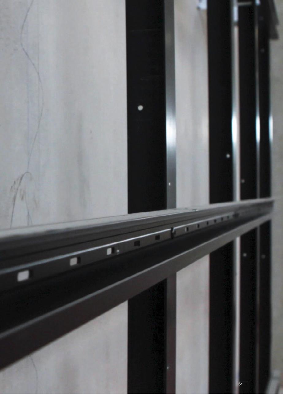
5151

52
LOGISTICA DI CANTIERE GHL MAXI LIGHTGHL Maxi Light site logistics
INVOLUCRO A SECCO - DRY ENVELOPES
La dimensione dei pannelli GHL Maxi Light permette, nella maggior parte dei casi, di utilizzare i tradizionali ponteggi, e quindi la logistica di cantiere sarà
del tutto simile a quella di una facciata ventilata tradizionale in ceramica; come esemplificazione si indicano le seguenti famiglie:
Accesso del personale in quota:
- Ponteggi fissi
- Ponteggimobili
Movimentazione e posa:
- Gru di cantiere
- Gru mobile
In most cases, the size of the GHL Maxi Light panels allows the use of conventional scaffolding, and site logistics are therefore very similar to those for
assembling traditional ceramic ventilated façades; as an example the following families are indicated:
Access for staff working at a height:
- Fixed scaffolding
- Mobile scaffolding
Handling and laying:
- Site crane
- Mobile crane

53
RIVESTIMENTO GHL MAXI LIGHT RANGE DIMENSIONALE E UTILIZZOGHL Maxi Light covering system size range and use -
INVOLUCRO A SECCO - DRY ENVELOPES
IL SISTEMA COMPRENDE - THE BASE SYSTEM INCLUDES:
Isolamente a cappotto tipo XPS o EPSXPS, EPS or other types of insulating material
Retinatura sul retro lastra Meshing on the rear of the porcelain stoneware slab
SottostrutturaSub-frame
NOTE: Si ricorda che il range dimensionale è puramente indicativo, poiché è possibile realizzare rivestimenti in esterno con lastre di tutte le dimensioni, fino al formato pieno (180x150 cm). - The size range is purely indicative, as external coverings can be produced using slabs of all sizes (up to 180x150 cm).
La legenda si riferisce all’altezza fuoriterra dell’edificio - The key refers to the height above ground of the building.
XPS: Polistirene estruso - Extruded polystyreneEPS: Polistirene espanso sinterizzato - Sintered expanded polystyrene
750 1000 1200 1500 1800 2250 3000
750
1000
1200
1500
1800
2250
3000

54
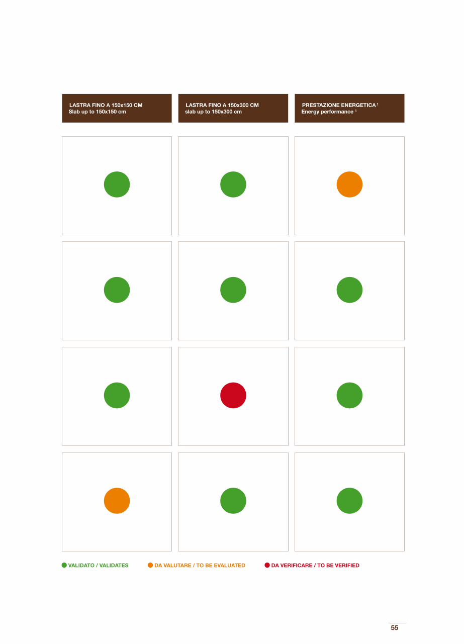
TAVOLA SINOTTICA: DOVE E QUANDO UTILIZZARE I SISTEMI DI RIVESTIMENTOSynoptic table: ehere and when to use the cladding system
1) La prestazione energetica si riferisce alla possibilità di inserire nel sistema uno strato di isolante termico1) The energy performance is related to the possible insertion of a thermal insulation layer within the system
SISTEMA SAFETY CLIP Safety Clip system Involucro a umido Wet envelopes
SISTEMA MICRO Micro system Involucro a secco Dry envelopes
SISTEMA A CAPPOTTO Thermal cladding system Involucro a umido Wet envelopes
SISTEMA FACCIATA VENTILATA Ventilated façade Involucro a secco Dry envelopes
SISTEMA System
ALTEZZA FINO A 20 MT Height up to 20 MT
ALTEZZA OLTRE A 20 MT Height over 20 MT
55
VALIDATO / VALIDATES DA VALUTARE / TO BE EVALUATED DA VERIFICARE / TO BE VERIFIED
LASTRA FINO A 150x150 CM Slab up to 150x150 cm
LASTRA FINO A 150x300 CM slab up to 150x300 cm
PRESTAZIONE ENERGETICA 1
Energy performance 1
56
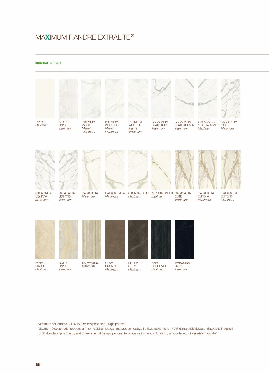
MAXIMUM FIANDRE EXTRALITE ®
300x150 120”x60”
- Maximum nel formato 3000x1500x6mm pesa solo 14kgs per m2.
- Maximum è sostenibile: propone all'interno dell'ampia gamma prodotti realizzati utilizzando almeno il 40% di materiale riciclato, rispettano i requisiti
LEED (Leadership in Energy and Environmental Design) per quanto concerne il criterio 4.1, relativo al “Contenuto di Materiale Riciclato”.
TAXOSMaximum
BRIGHT ONYXMaximum
PREMIUMWHITEMarmiMaximum
PREMIUMWHITE/ AMarmiMaximum
PREMIUMWHITE/ BMarmiMaximum
CALACATTALIGHT Maximum
CALACATTASTATUARIOMaximum
CALACATTASTATUARIO/ A Maximum
CALACATTASTATUARIO/ B Maximum
CALACATTAELITE Maximum
CALACATTAELITE/ A Maximum
CALACATTAELITE/ B Maximum
IMPERIAL WHITEMaximum
CALACATTALIGHT/ B Maximum
CALACATTALIGHT/ A Maximum
CALACATTA/ AMaximum
CALACATTA/ BMaximum
CALACATTAMaximum
GLAM BRONZEMaximum
GOLD ONYXMaximum
ROYAL MARFILMaximum
TRAVERTINOMaximum
MARQUINA DARKMaximum
NERO SUPREMOMaximum
PIETRAGREYMaximum

57
- In the 300x150x0.6 cm format, Maximum only weighs 14 kg/m2.
- Maximum is sustainable: the products have been manufactured using at least 40% of recycled material, they comply with LEED (Leadership in Energy
and Environmental Design) requirements as regards criterion 4.1 regarding “Recycled Material Content”.
MEGAWHITEMegalith Maximum
MEGAGREIGEMegalithMaximum
MEGABROWNMegalithMaximum
MEGAGREYMegalithMaximum
MEGABLACKMegalithMaximum
QUIET SANDQuietstonesMaximum
QUIET ROCKQuietstonesMaximum
QUIET NUMBQuietstonesMaximum
VENUSAsterMaximum
MERCURYAsterMaximum
MOONAsterMaximum
WHITE RESINHQ.ResinMaximum
CINDER RESINHQ.ResinMaximum
DARK RESINHQ.ResinMaximum
GREY RESINHQ.ResinMaximum

58
GLOSSARIO
ASSEMBLAGGIO A SECCO
Modalità costruttiva che non prevede l’utilizzo di collanti per l’assiemaggio dei componenti del sistema.
COIBENTAZIONE / STRATO COIBENTE
Strato di isolamento termico posto a ridosso di un elemento della costruzione. Esso può essere realizzato con diverse tipologie di materiale isolante,
da scegliere in funzione del progetto.
FABBISOGNO ENERGETICO
Quantità di energia primaria (solitamente espressa in TEP – tonnellate equivalenti di petrolio) necessaria per il mantenimento delle condizioni ambientali
di comfort all’interno degli spazi. Esso è influenzato in prima istanza dalle caratteristiche compositive dell’involucro edilizio e dalla sua capacità di con-
tenere l’energia spesa per il riscaldamento e il raffrescamento degli spazi.
FACCIATA VENTILATA
Sistema di rivestimento multistrato per pareti di edifici esistenti o di nuova costruzione, posata a secco e costituita da uno strato esterno impermeabile
di finitura (in lastre di ceramica, ceramica tecnica, pannelli in alluminio, in acciaio, PVC etc), da uno strato intermedio di isolante, applicato direttamente
alla parete esistente e da una struttura in metallo ancorata alla struttura portante dell’edificio. Tra lo strato isolante e rivestimento si determina una
intercapedine che, per “effetto camino”, attiva un’efficace ventilazione naturale, che contribuisce al controllo del flusso energetico che passa attraverso
la parete.
GIUNTO
Punto del rivestimento in cui due o più elementi si interfacciano tra loro in modo fisso o mobile. Il giunto in un sistema di rivestimento a parete ventilata
può essere aperto o chiuso
INDICE DI RIFLESSIONE (IR)
Unità di misura della riflessione della luce diurna (irraggiamento – per ddare una indicazione, l’indice di riflessione del bianco è 100% e del nero 0%).
INTERCAPEDINE
Spazio vuoto tra due superfici (per esempio lastre o pareti).
ISOLAMENTO A CAPPOTTO
Il sistema d’isolamento a cappotto consiste nel rivestimento delle pareti esterne con pannelli isolanti, in grado di proteggere gli strati sottostanti senza
rimuovere il vecchio intonaco.
ISOLANTE
Materiale che ha impedisce o rallenta il passaggio di calore (isolante termico) o del suono (isolante acustico) da un ambiente all’altro o attraverso un
elemento della costruzione.
PANNELLO ISOLANTE EPS
Pannello isolante in polistirene espanso.
PANNELLO ISOLANTE IN XPS
Pannello isolante in polistirene espanso estruso.
PONTE TERMICO
Elemento o connessione che consente, per contatto, il passaggio di calore tra due componenti a temperatura diversa. Nei sistemi di rivestimento, ha
valenza negativa in quanto favorisce la dispersione termica attraverso gli elementi della costruzione non opportunamente isolati, specialmente nei mesi
invernali.
TRASMITTANZA
Quantità di calore ceduta dall’ambiente interno attraverso una superficie di 1 mq a temperature costanti e con differenza di temperatura di 1 K.
59
GLOSSARY
DRY LAYING
Construction methods without the use of glues to assemble the system components.
INSULATION/INSULATING LAYER
Layer of thermal insulation laid against a construction element. It may be made from various types of insulating material, chosen according to the
specific project.
ENERGY REQUIREMENT
Amount of primary energy (usually expressed in TEP – tonnes equivalent of petrol) needed to maintain environmental conditions of comfort inside a
space. It is affected first and foremost by the composition of the building envelope and its ability to reduce energy expenditure for heating and cooling.
VENTILATED FAÇADE
Multi-layer covering of existing or new buildings, laid dry and comprising a waterproof external finishing layer (ceramic slab, technical ceramics, alu-
minium, steel or PVC panels, etc.), an intermediate insulating layer, applied directly to the existing wall or a metal frame anchored to the load-bearing
structure of the building. A cavity wall is created between the outer covering and the insulating layer, which creates a “chimney effect” to ensure effective
natural ventilation, helping to control the energy flow through the wall.
JOINT
Point in the covering where two or more elements are connected together in a fixed or mobile manner. The joint in a ventilated wall covering may be
open or closed.
REFLECTIVE INDEX (RI)
Unit of measure of the daytime light reflectance (irradiation – to give an idea, white reflection is 100% and black 0%).
CAVITY WALL
Empty space between two surfaces (e.g. slab and wall).
THERMAL CLADDING
Thermal cladding involves the covering of external walls with insulating panels that protect the underlying layers without removing the existing plaster.
INSULATING LAYER
Material that prevents or reduces the passage of heat (thermal insulation) or sound (acoustic insulation) between one space and another or through a
construction element.
EPS INSULATING PANEL
Insulating panel in expanded polystyrene.
XPS INSULATING PANEL
Insulating panel in extruded polystyrene.
THERMAL BRIDGE
Element or connection which, by contact, allows the passage of heat between two components with different temperatures. In covering systems, it
is a negative element as it facilitates heat dispersion through any construction elements that are not appropriately insulated, particularly in the winter
months.
THERMAL TRANSMITTANCE
Quantity of heat transferred from the inside through a 1 m2 surface area at a constant temperature and with a temperature difference of 1 K.

© 2013 - 2014 GranitiFiandre S.p.A - Tutti i diritti riservati. E’ vietata la riproduzione, anche parziale, di immagini, testi o contenuti.
© 2013 - 2014 GranitiFiandre S.p.A - All rights reserved. Reproduction in whole or in part of the images, texts or contents is prohibited.
print 09/2017

60
PROUDLY ITALIAN
GranitiFiandre spavia Radici Nord, 11242014 Castellarano (RE) Italytel. +39 0536 819611fax +39 0536 [email protected] www.granitifiandre.com
CA
MC
0214