![PPT BOULANGER [Lecture seule]](https://static.fdocuments.fr/doc/165x107/62b15dfb7a4e8138327cf3db/ppt-boulanger-lecture-seule.jpg)
LECTURE-3-BEC304 .ppt
35
LESSON 3 Laterally Unrestrained Beam
-
Upload
mohd-nizam-shakimon -
Category
Documents
-
view
214 -
download
0
Transcript of LECTURE-3-BEC304 .ppt
7/27/2019 LECTURE-3-BEC304 .ppt
http://slidepdf.com/reader/full/lecture-3-bec304-ppt 1/35
LESSON 3Laterally Unrestrained Beam
7/27/2019 LECTURE-3-BEC304 .ppt
http://slidepdf.com/reader/full/lecture-3-bec304-ppt 2/35
OUTLINES
Lateral torsional buckling
Factors influencing LTBEffect of non-uniform moment
Buckling resistance moment
Design procedure
Design example
7/27/2019 LECTURE-3-BEC304 .ppt
http://slidepdf.com/reader/full/lecture-3-bec304-ppt 3/35
Introduction
in beam design , usual to think first of need toprovide adequate strength and stiffness against
vertical bending.
leads naturally to x-section in which stiffnessis much larger in vertical than in horizontal
planes.
sections normally used as beams have:-majority of material concentrated in flanges.
flanges which are relatively narrow so as to
prevent local buckling.
7/27/2019 LECTURE-3-BEC304 .ppt
http://slidepdf.com/reader/full/lecture-3-bec304-ppt 4/35
for ease of connection with adjacentmembers, beams of open sections (I or
H) are commonly used.
whenever a slender structural elementis loaded in its stiff plane, there is a
tendency for it to fail by buckling in the
more flexible plane.
compression flange of an I-beam acts
like a column, i.e.:
Introduction (cont.)
7/27/2019 LECTURE-3-BEC304 .ppt
http://slidepdf.com/reader/full/lecture-3-bec304-ppt 5/35
buckles sideways if beam not
sufficiently stiff.
or not retrained laterally.
load at which beam buckles can be
much less than that causing full
moment capacity.
Introduction (cont.)
7/27/2019 LECTURE-3-BEC304 .ppt
http://slidepdf.com/reader/full/lecture-3-bec304-ppt 6/35
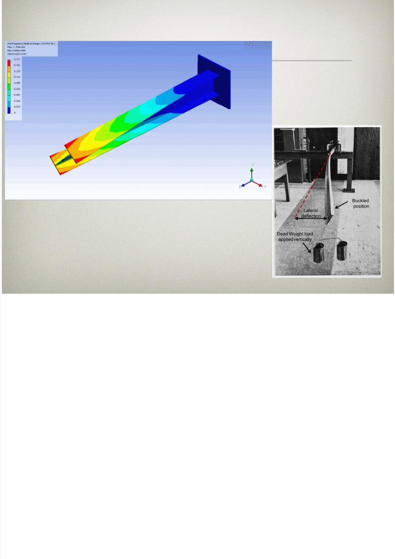
Dead Weight load
applied vertically
Buckled
positionLateral
deflection

7/27/2019 LECTURE-3-BEC304 .ppt
http://slidepdf.com/reader/full/lecture-3-bec304-ppt 7/35
Introduction (cont.)
The beam is said in satisfactory when
its cross-sectional and bucklingcapacities are not exceeded.
MEd ≤ Mc, Rd (in-plane buckling)
Med ≤ Mb,Rd (out-of plane buckling)
7/27/2019 LECTURE-3-BEC304 .ppt
http://slidepdf.com/reader/full/lecture-3-bec304-ppt 8/35
Lateral Torsional Buckling
LTB is a type of instability.
Similar to flexural buckling of an
axially loaded strut.But more complex as it involves
both lateral deflection u and twist .
Loading beam in stiffer plane (planeof the web) has induced a failure by
buckling in a less stiff direction.
7/27/2019 LECTURE-3-BEC304 .ppt
http://slidepdf.com/reader/full/lecture-3-bec304-ppt 9/35
Lateral Torsional Buckling (cont.)
LTB may be effectively prevented by
many types of construction thereby
enabling more efficient beam design.
Normal beam and slabconstruction is an example where
the member is restrained to
prevent buckling.However during erection, beam
may receive far less lateral support
– thus stability must be verified.
7/27/2019 LECTURE-3-BEC304 .ppt
http://slidepdf.com/reader/full/lecture-3-bec304-ppt 10/35
Lateral Torsional Buckling (cont.)
LTB influences design of laterallyunrestrained beams in same way that
flexural buckling influences column
design.
Due to LTB, bending strength now a
function of beam slenderness.
Design procedure somewhat more
complex and lengthier.
Situations where lateral torsional
buckling has to be taken into account
are less common.

7/27/2019 LECTURE-3-BEC304 .ppt
http://slidepdf.com/reader/full/lecture-3-bec304-ppt 11/35
Factors Influencing LTB
Unbraced span
Distance between points at which
lateral deflection is prevented.Beam weaker as unbraced span
gets longer.
LTB prevented by providing propsat intermediate points.

7/27/2019 LECTURE-3-BEC304 .ppt
http://slidepdf.com/reader/full/lecture-3-bec304-ppt 12/35
Factors Influencing LTB (cont.)
Uniform or Non-uniform Moments
Shape of BMD between restraints
affects stability.If non-uniform, force in
compression flange not constant.
Member expected to be morestable.
7/27/2019 LECTURE-3-BEC304 .ppt
http://slidepdf.com/reader/full/lecture-3-bec304-ppt 13/35
Factors Influencing LTB (cont.)
Section shape
Sections with greater lateral
bending (EIz) and torsional stiffness
(GJ) have greater resistance tobuckling.
Nature of End-Restraint of Beam
End-restraints which inhibitdevelopment of buckling shape
likely to increase stability
7/27/2019 LECTURE-3-BEC304 .ppt
http://slidepdf.com/reader/full/lecture-3-bec304-ppt 14/35
Behaviour of Beam
Short stocky members will attain the
full plastic moment Mp.Long slender members will fail at
moments approximately equal to the
elastic critical moment ME.

7/27/2019 LECTURE-3-BEC304 .ppt
http://slidepdf.com/reader/full/lecture-3-bec304-ppt 15/35
a era ors ona uc ngResistance
Verification should be carried out on
all unrestrained of beams (between
the points where lateral restraints
exist).
7/27/2019 LECTURE-3-BEC304 .ppt
http://slidepdf.com/reader/full/lecture-3-bec304-ppt 16/35
Methods to verify LTB
The primary method adopts the
lateral torsional buckling curves given
in equations 6.56 and 6.57 and are
set out in clauses 6.3.2.2 and 6.3.2.3.
7/27/2019 LECTURE-3-BEC304 .ppt
http://slidepdf.com/reader/full/lecture-3-bec304-ppt 17/35
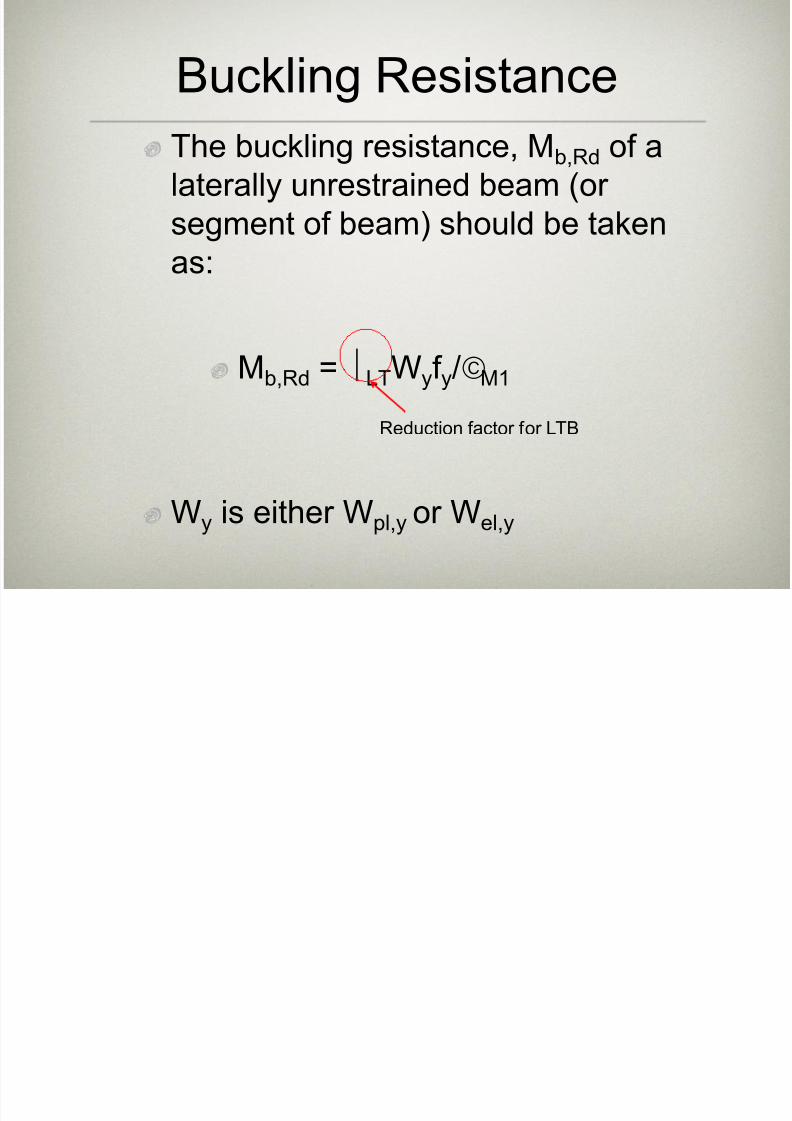
Buckling Resistance
The buckling resistance, Mb,Rd of alaterally unrestrained beam (or
segment of beam) should be taken
as:
Mb,Rd = LTWyf y/M1
Wy is either Wpl,y or Wel,y
Reduction factor for LTB
7/27/2019 LECTURE-3-BEC304 .ppt
http://slidepdf.com/reader/full/lecture-3-bec304-ppt 18/35
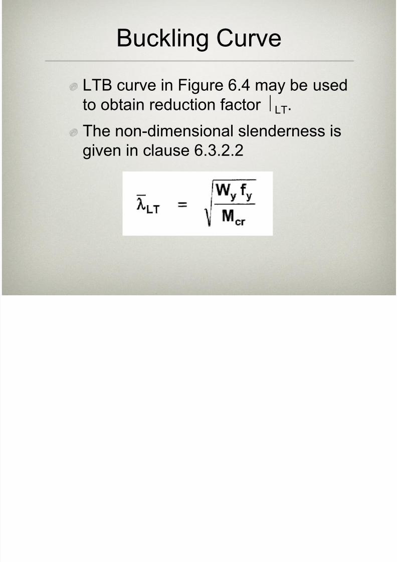
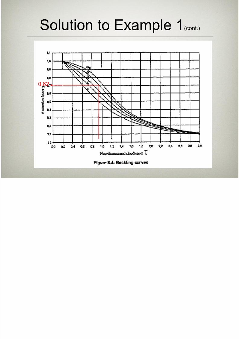
Buckling Curve
LTB curve in Figure 6.4 may be used
to obtain reduction factor LT.
The non-dimensional slenderness isgiven in clause 6.3.2.2

7/27/2019 LECTURE-3-BEC304 .ppt
http://slidepdf.com/reader/full/lecture-3-bec304-ppt 19/35
Buckling Curve(cont.)
Mcr is the elastic critical LTB moment.However EC3 does not provide any
method to obtain the value!!
L. Gardner proposes a simplifiedmethod for non-uniform and uniform
moments, i.e. :
7/27/2019 LECTURE-3-BEC304 .ppt
http://slidepdf.com/reader/full/lecture-3-bec304-ppt 20/35
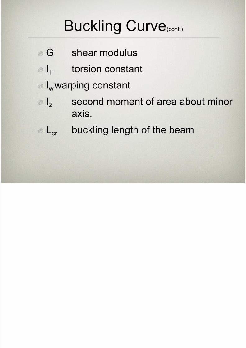
Buckling Curve(cont.)
G shear modulus
IT torsion constant
Iwwarping constantIz second moment of area about minor
axis.
Lcr buckling length of the beam

7/27/2019 LECTURE-3-BEC304 .ppt
http://slidepdf.com/reader/full/lecture-3-bec304-ppt 21/35
Buckling Curve(cont.)
Simplified method of obtaining
slenderness ratio:
7/27/2019 LECTURE-3-BEC304 .ppt
http://slidepdf.com/reader/full/lecture-3-bec304-ppt 22/35
Example 1
7/27/2019 LECTURE-3-BEC304 .ppt
http://slidepdf.com/reader/full/lecture-3-bec304-ppt 23/35
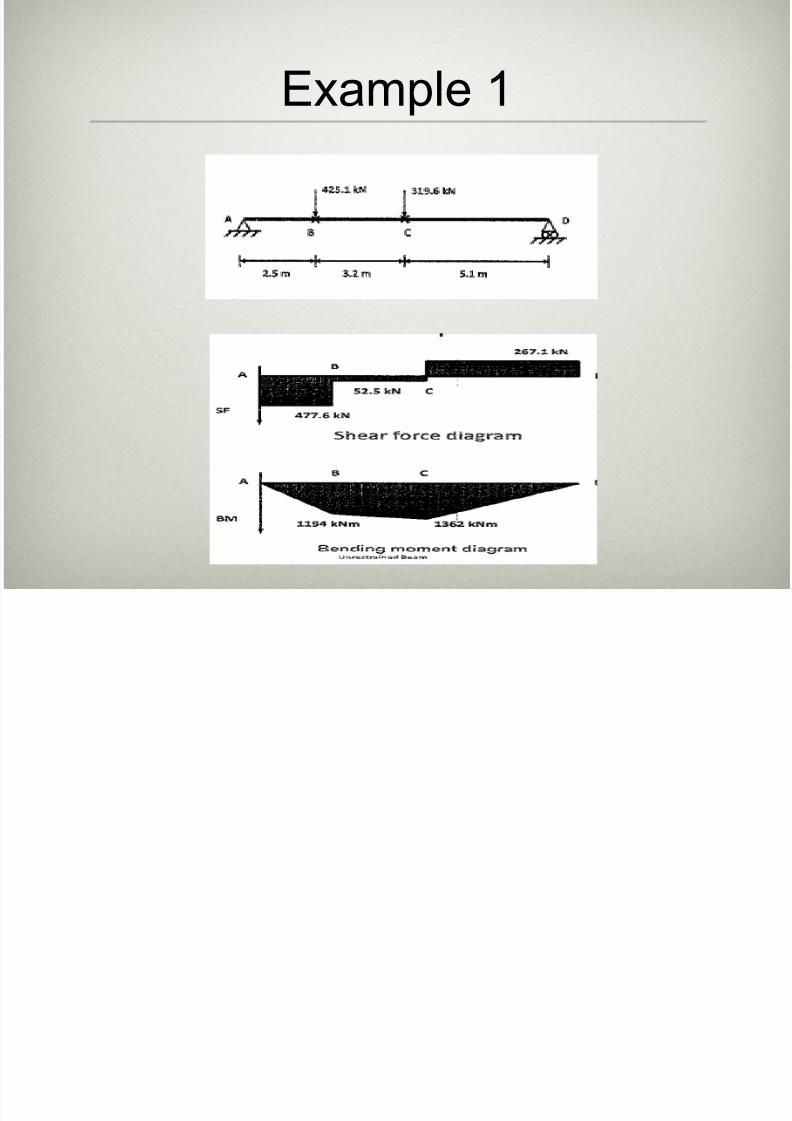
Example 1(cont.)
The simply supported beam shown in the
figure is restraint at points B and C.
Check the beam for lateral torsionalbuckling. Try 762x267x173 UKB of S275
steel EN10025-2.
7/27/2019 LECTURE-3-BEC304 .ppt
http://slidepdf.com/reader/full/lecture-3-bec304-ppt 24/35
Solution to Example 1(cont.)
By inspection, segment AB is not critical. LTB
will be investigated along spans BC and CDonly.
7/27/2019 LECTURE-3-BEC304 .ppt
http://slidepdf.com/reader/full/lecture-3-bec304-ppt 25/35
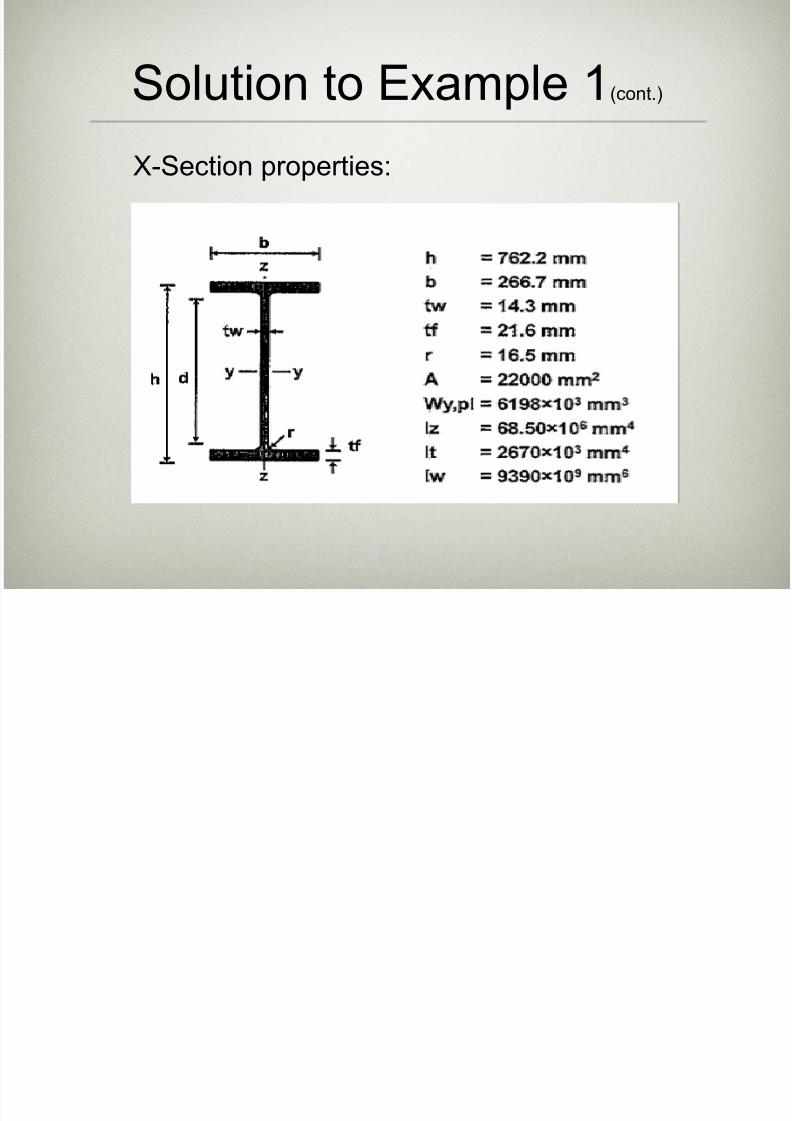
X-Section properties:
Solution to Example 1(cont.)

7/27/2019 LECTURE-3-BEC304 .ppt
http://slidepdf.com/reader/full/lecture-3-bec304-ppt 26/35
1. Section classification
• From Table 3.1:
tf =21.6mm and tw=14.3mm; EN10025-2
Therefore, f y=275N/mm2
From clause 3.2.6, E=210000N/mm2 and
G=81000N/mm2.
Solution to Example 1(cont.)
7/27/2019 LECTURE-3-BEC304 .ppt
http://slidepdf.com/reader/full/lecture-3-bec304-ppt 27/35
From Table 5.2: out-stand flanges
=0.92
cf /tf = 5.08 < 9
Flanges are class 1
Solution to Example 1(cont.)
7/27/2019 LECTURE-3-BEC304 .ppt
http://slidepdf.com/reader/full/lecture-3-bec304-ppt 28/35
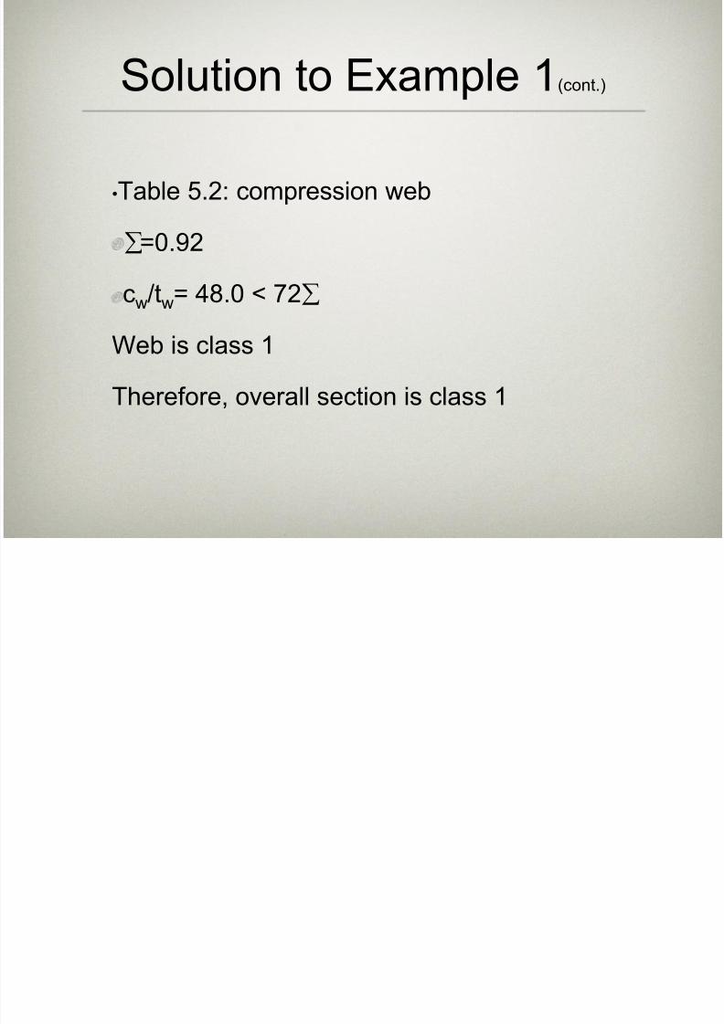
•Table 5.2: compression web
=0.92
cw/tw= 48.0 < 72
Web is class 1
Therefore, overall section is class 1
Solution to Example 1(cont.)
7/27/2019 LECTURE-3-BEC304 .ppt
http://slidepdf.com/reader/full/lecture-3-bec304-ppt 29/35
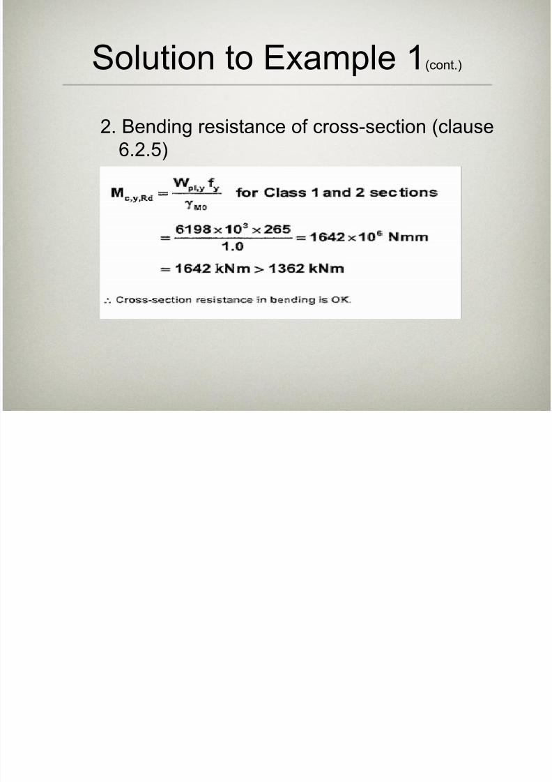
2. Bending resistance of cross-section (clause
6.2.5)
Solution to Example 1(cont.)

7/27/2019 LECTURE-3-BEC304 .ppt
http://slidepdf.com/reader/full/lecture-3-bec304-ppt 30/35
3. Buckling resistance, Mb,Rd (clause 6.3.2.1)
Mb,Rd = LTWyf y/M1
For span BC (Lcr =3.1m):
λLT = Lcr /96iz= 3100/96x55.8
= 0.6
From Table 6.4:
I-section, h/b = 762.2/266.7
= 2.9>2.0
Solution to Example 1(cont.)
7/27/2019 LECTURE-3-BEC304 .ppt
http://slidepdf.com/reader/full/lecture-3-bec304-ppt 31/35
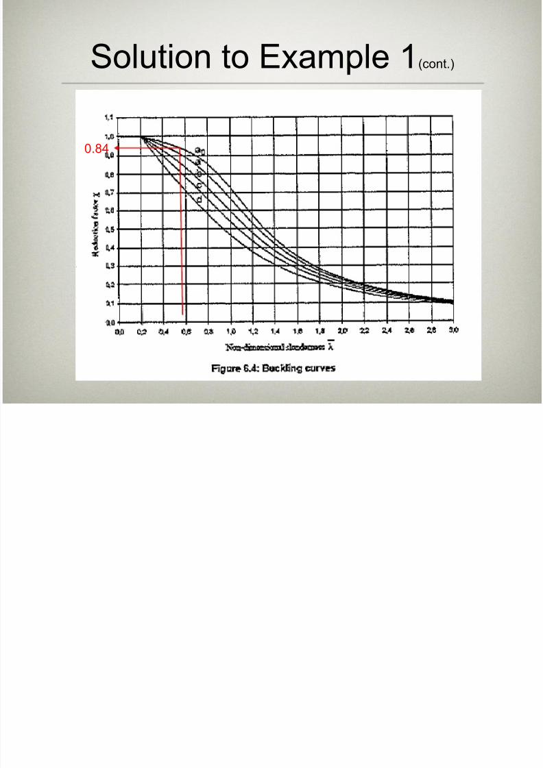
Solution to Example 1(cont.)
0.84
7/27/2019 LECTURE-3-BEC304 .ppt
http://slidepdf.com/reader/full/lecture-3-bec304-ppt 32/35
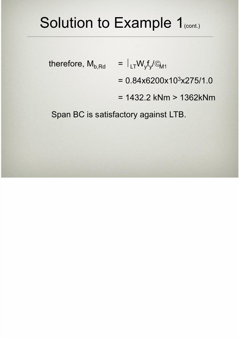
therefore, Mb,Rd = LTWyf y/M1
= 0.84x6200x10
3
x275/1.0= 1432.2 kNm > 1362kNm
Span BC is satisfactory against LTB.
Solution to Example 1(cont.)
7/27/2019 LECTURE-3-BEC304 .ppt
http://slidepdf.com/reader/full/lecture-3-bec304-ppt 33/35
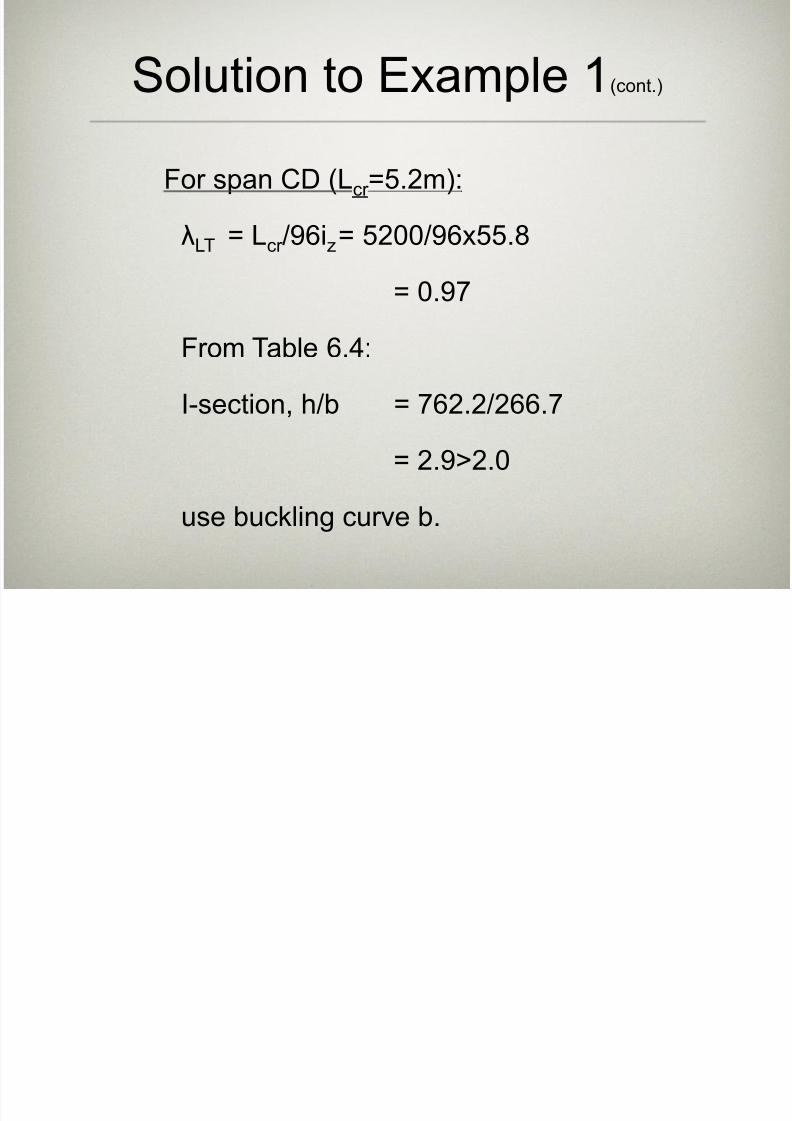
For span CD (Lcr =5.2m):
λLT = Lcr /96iz= 5200/96x55.8
= 0.97
From Table 6.4:
I-section, h/b = 762.2/266.7
= 2.9>2.0
use buckling curve b.
Solution to Example 1(cont.)
7/27/2019 LECTURE-3-BEC304 .ppt
http://slidepdf.com/reader/full/lecture-3-bec304-ppt 34/35
Solution to Example 1(cont.)
0.62
7/27/2019 LECTURE-3-BEC304 .ppt
http://slidepdf.com/reader/full/lecture-3-bec304-ppt 35/35
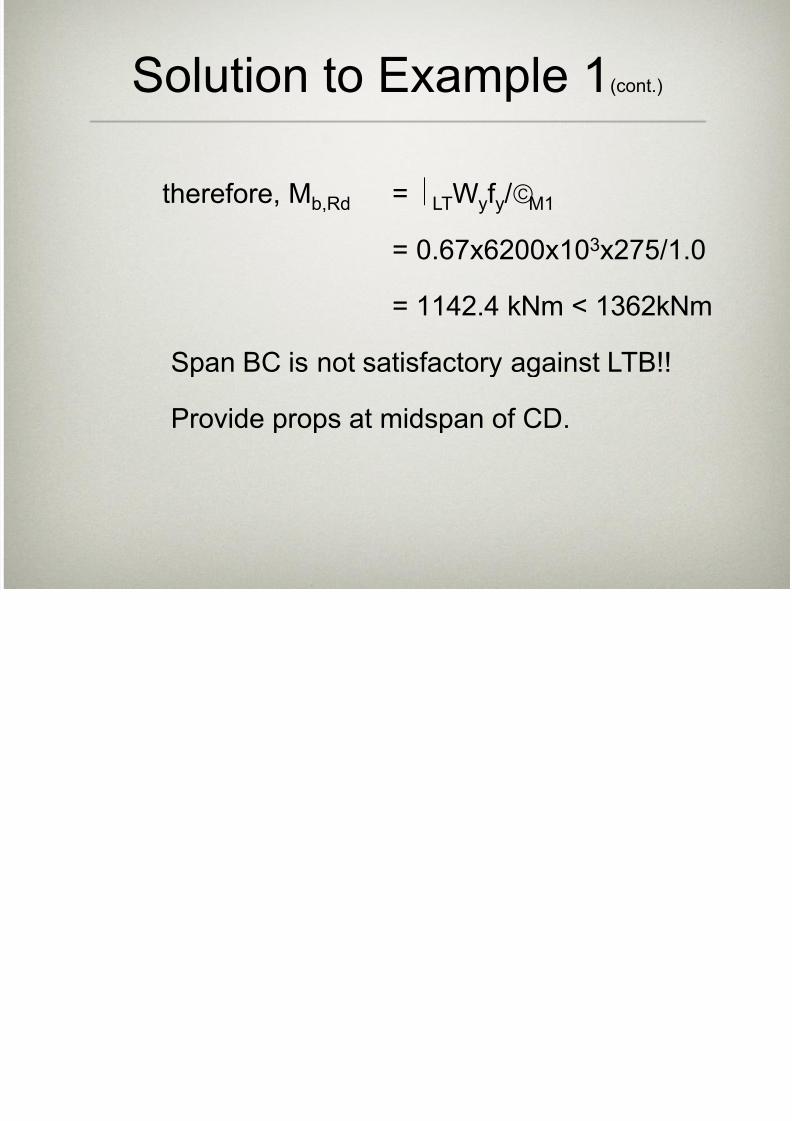
therefore, Mb,Rd = LTWyf y/M1
= 0.67x6200x103x275/1.0
= 1142.4 kNm < 1362kNm
Span BC is not satisfactory against LTB!!
Provide props at midspan of CD.
Solution to Example 1(cont.)


![Ppt0000007.ppt [Lecture seule] - Fondation MAIF · Microsoft PowerPoint - Ppt0000007.ppt [Lecture seule] Author lesaux Created Date 4/23/2015 2:16:08 PM ...](https://static.fdocuments.fr/doc/165x107/5fd28bed28d6470ec658bd3b/lecture-seule-fondation-maif-microsoft-powerpoint-lecture-seule-author-lesaux.jpg)

![atelier CFA tryptasemie MAILHOL final[1].ppt (Lecture seule)](https://static.fdocuments.fr/doc/165x107/62aae724515b444d79668356/atelier-cfa-tryptasemie-mailhol-final1ppt-lecture-seule.jpg)


![Midi- Pyrénées 2030 · Microsoft PowerPoint - Ppt0000007.ppt [Lecture seule] Author: LENORMAP Created Date: 4/26/2013 15:25:57 ...](https://static.fdocuments.fr/doc/165x107/60021fa62740ef70c777ebf9/midi-pyrnes-2030-microsoft-powerpoint-ppt0000007ppt-lecture-seule-author.jpg)

![Ppt0000007.ppt [Lecture seule] - Créer un blog gratuitement sur …laprohistgeo.a.l.f.unblog.fr/files/2013/02/modele-diapo... · 2015. 10. 13. · Title: Microsoft PowerPoint - Ppt0000007.ppt](https://static.fdocuments.fr/doc/165x107/601b4a01b10a3c05b7402370/lecture-seule-crer-un-blog-gratuitement-sur-laprohistgeoalfunblogfrfiles201302modele-diapo.jpg)
![Collège 3 [ppt]](https://static.fdocuments.fr/doc/165x107/55c50e18bb61eb3c368b456f/college-3-ppt.jpg)
![Ppt0000030.ppt [Lecture seule] - ESKA](https://static.fdocuments.fr/doc/165x107/62acf6c05925910df375668d/-lecture-seule-eska.jpg)
![Pr.sentation AG2004 Magnitude78.ppt [Lecture seule] · Objectifs 1- mise en route de MUSICOS 2- acquisition d ’un savoir-faire en spectroscopie 3- découverte de la station pour](https://static.fdocuments.fr/doc/165x107/5e416e530c9c0f36be125083/prsentation-ag2004-lecture-seule-objectifs-1-mise-en-route-de-musicos-2-acquisition.jpg)

![LL ERGOTHERAPIE’ERGOTHERAPIE EN EN … · repas, aidee--mméèénagère ... (Dr FARDJAD).ppt [Lecture seule] [Mode de compatibilité] Author: Administrateur Created Date: 3/26/2009](https://static.fdocuments.fr/doc/165x107/5bb9065a09d3f2751e8e18da/ll-ergotherapieergotherapie-en-en-repas-aidee-mmeeenagere-dr-fardjadppt.jpg)

![Ppt0000197.ppt [Lecture seule]](https://static.fdocuments.fr/doc/165x107/61689284d394e9041f70b8ae/-lecture-seule.jpg)