International Standard 255
7
International Standard @ 255 ~~ ~ ~ INTERNATIONAL ORGANIZATION FOR STANOARDIZATlON*MEXAYHAPOAHAR OPrAHH3AUHR no CTAHL\APTH3AUHH.ORGANlSATlON INTERNATIONALE DE NORMALISATION L. Pulleys for classical and narrow V-belts - Geometrical inspection of grooves Poulies pour courroies trapézoïdales classiques et étroites - Vérification géométrique des gorges First edition - 1981-08-01 - UDC 621.85.051 : 621.85.052.42 Ref. No. IS0 256-1981 (E) E Descriptors : pulleys, grooved pulleys, belts, V-belts, geometric characteristics, dimensional measurement. H Price based on 4 pages iTeh STANDARD PREVIEW (standards.iteh.ai) ISO 255:1981 https://standards.iteh.ai/catalog/standards/sist/3fff6a6d-a08a-4f4a-b0c3- 5ea7345f4114/iso-255-1981
Transcript of International Standard 255

International Standard @ 255 ~~ ~ ~
INTERNATIONAL ORGANIZATION FOR STANOARDIZATlON*MEXAYHAPOAHAR OPrAHH3AUHR no CTAHL\APTH3AUHH.ORGANlSATlON INTERNATIONALE DE NORMALISATION
L. Pulleys for classical and narrow V-belts - Geometrical inspection of grooves Poulies pour courroies trapézoïdales classiques et étroites - Vérification géométrique des gorges
First edition - 1981-08-01
- UDC 621.85.051 : 621.85.052.42 Ref. No. IS0 256-1981 (E) E
Descriptors : pulleys, grooved pulleys, belts, V-belts, geometric characteristics, dimensional measurement. H Price based on 4 pages
iTeh STANDARD PREVIEW(standards.iteh.ai)
ISO 255:1981https://standards.iteh.ai/catalog/standards/sist/3fff6a6d-a08a-4f4a-b0c3-
5ea7345f4114/iso-255-1981
Foreword IS0 (the International Organization for standardization) is a worldwide federation of national standards institutes (IS0 member bodies). The work of developing Inter- national Standards is carried out through IS0 technical committees. Every member body interested in a subject for which a technical committee has been set up has the right to be represented on that committee. International organizations, governmental and non-governmental, in liaison with ISO, also take part in the work.
Draft International Standards adopted by the technical committees are circulated to the member bodies for approval before their acceptance as International Standards by the IS0 Council.
International Standard IS0 255 was developed by Technical Committee ISO/TC 41, Pulleys and belts (including veebelts), and was circulated to the member bodies in June 1980.
It has been approved by the member bodies of the following countries
Austria India South Africa, Rep. of Belgium Ireland Spain Canada Italy Sweden Egypt, Arab Rep. of Japan United Kingdom Finland Korea, Dem. P. Rep. of USA France Korea, Rep. of USSR Germany, F. R. Romania
The member body of the following country expressed disapproval of the document on technical grounds :
Czechoslovakia
This International Standard cancels and replaces IS0 Recommendation R 255-1962, of which it constitutes a technical revision.
O International Organization for Standardization, 1981 O
Printed in Switzerland
iTeh STANDARD PREVIEW(standards.iteh.ai)
ISO 255:1981https://standards.iteh.ai/catalog/standards/sist/3fff6a6d-a08a-4f4a-b0c3-
5ea7345f4114/iso-255-1981
INTERNATIONAL STANDARD
Pulleys for classical and narrow V-belts - Geometrical inspection of grooves
1 Scope and field of application i
This International Standard specifies the requirements to ensure the regularity of the grooves of pulleys for classical and narrow V-belts and the methods of checking.
2 References
IS0 2861 1, I S 0 system of limits and fits - Part 1 : General, tolerances and deviations. 1)
I S 0 1081, Drives using V-belts and grooved pulleys - Ter- minolog y.
IS0 4183, Grooved pulleys for classical and narrow V-belts.
3 Principle
Complete inspection of a pulley groove (see figure 1) should be carried out in five successive checking operations, in the order given below :
i_
- Inspection of groove angle a (clause 4)
Inspection of outside diameter and cylindricity of the - pulley (clause 5)
- Inspection of datum diameter dd (clause 6)
- Inspection, for the various successive grooves of a single pulley, of height of groove above datum line (dimen- sion b ) (clause 7)
- Inspection of the concentricity of the datum cir- cumference (clause 8).
It should first of all be noted that what is important is the regularity of the grooves (regularity of form for one groove and
regularity from one groove to another), rather than exact knowledge of the datum diameter itself.
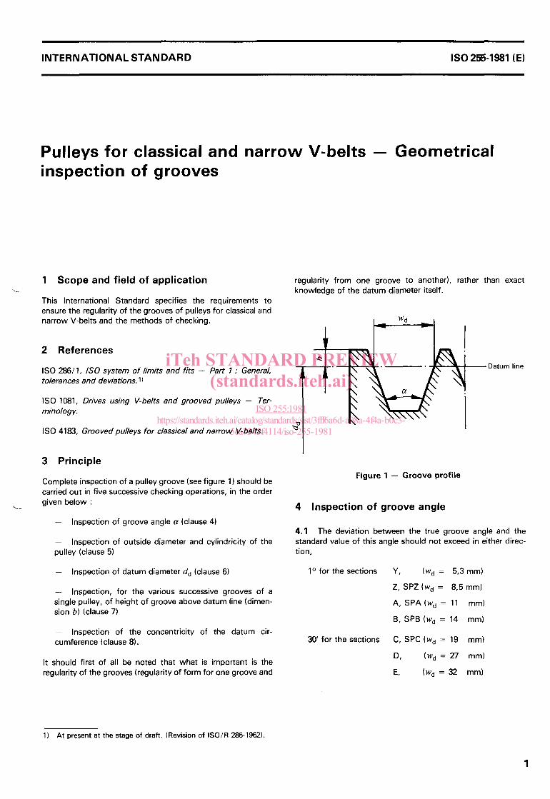
i 'Datum line
Figure 1 - Groove profile
4 Inspection of groove angle
4.1 The deviation between the true groove angle and the standard value of this angle should not exceed in either direc- tion,
io for the sections Y, (wd = 5,3 mm)
Z, SPZ (wd = 8,5 mm)
A, SPA(Wd = 11 mm)
B, SPB (wd = 14 mm)
3 0 for the sections C, SPC (wd = 19 mm)
D, (wd = 27 mm)
E, (wd = 32 mm)
1) At present at the stage of draft. (Revision of ISO/R 286-1962).
1
iTeh STANDARD PREVIEW(standards.iteh.ai)
ISO 255:1981https://standards.iteh.ai/catalog/standards/sist/3fff6a6d-a08a-4f4a-b0c3-
5ea7345f4114/iso-255-1981
I S 0 255-1981 (E)
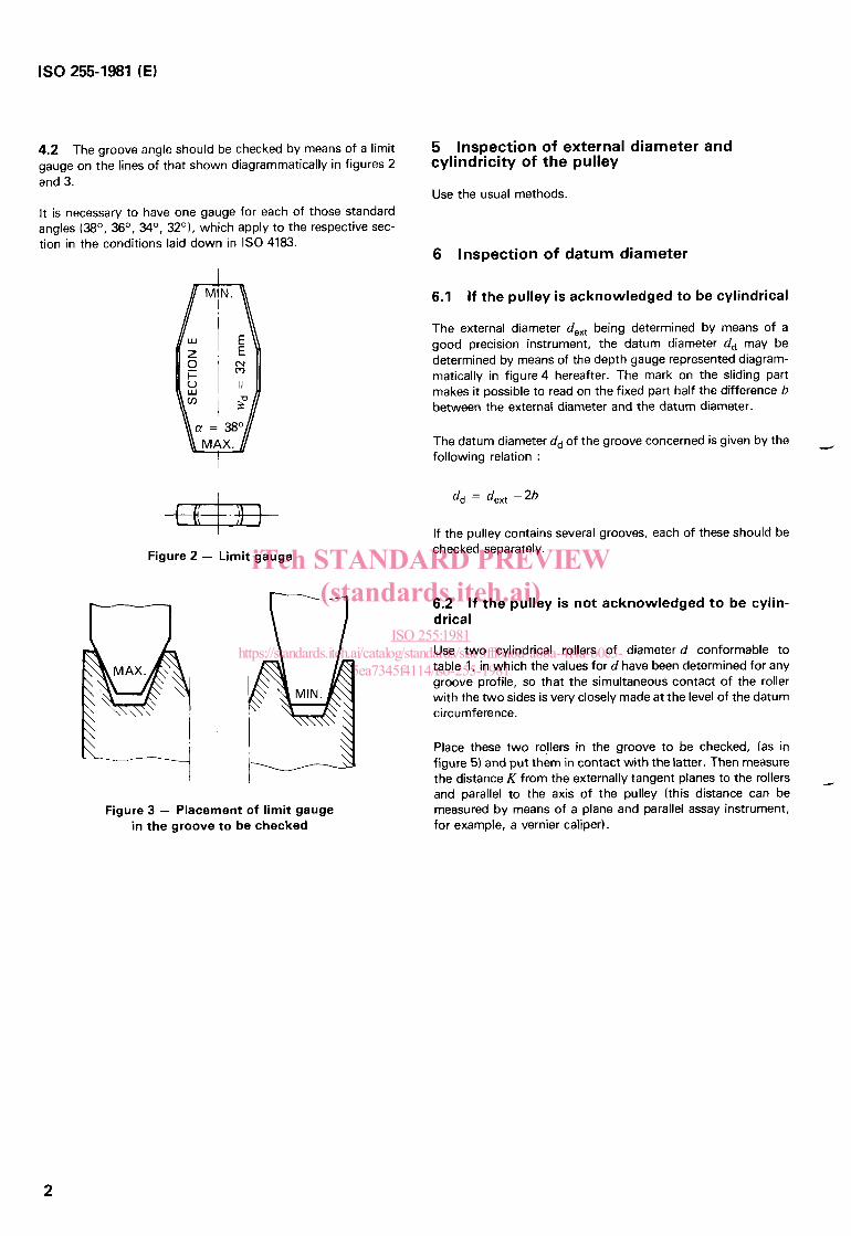
4.2 The groove angle should be checked by means of a limit gauge on the lines of that shown diagrammatically in figures 2 and 3.
It is necessary to have one gauge for each of those standard angles (Bo, 36O, %O, 32O), which apply to the respective sec- tion in the conditions laid down in IS0 4183.
a = 3 8 O MAX.
-=@- Figure 2 - Limit gauge
Figure 3 - Placement of limit gauge in the groove to be checked
5 cylindricity of the pulley
Inspection of external diameter and
Use the usual methods.
6 Inspection of datum diameter
6.1 If the pulley is acknowledged to be cylindrical
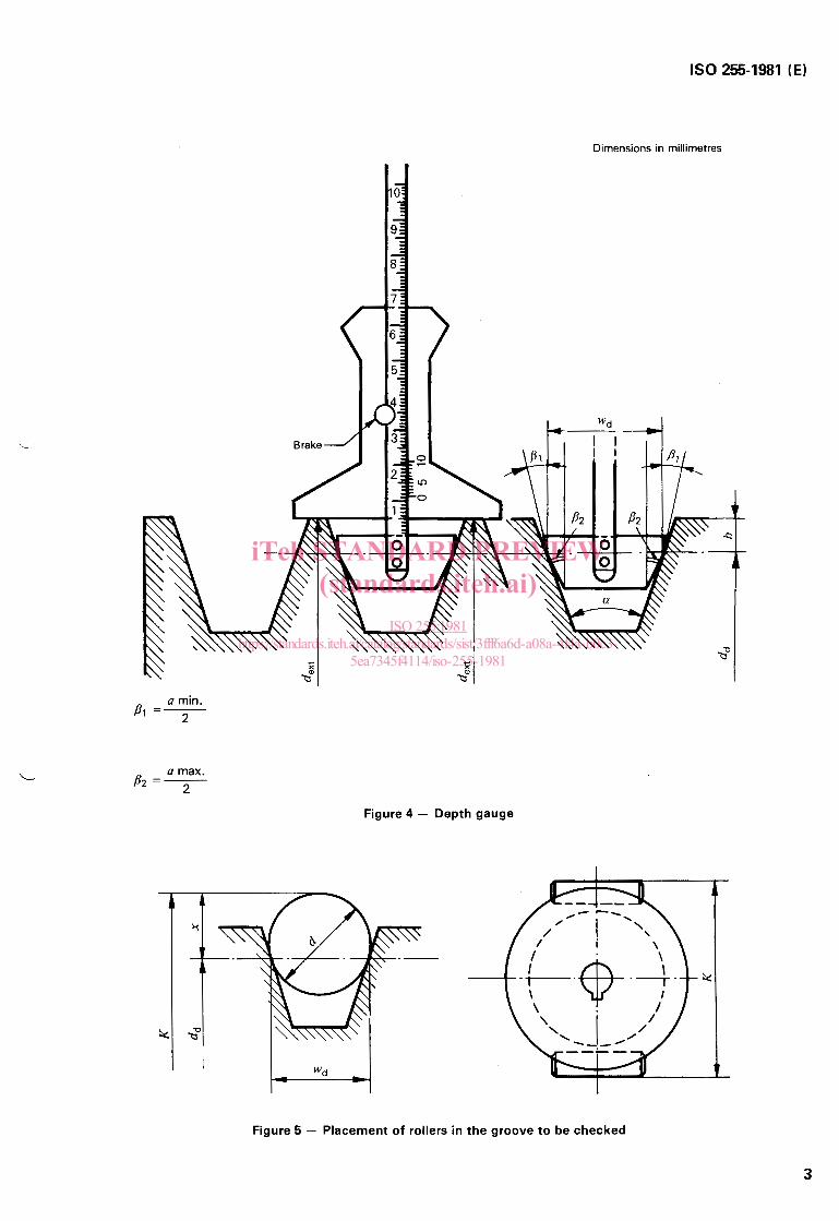
The external diameter de,, being determined by means of a good precision instrument, the datum diameter dd may be determined by means of the depth gauge represented diagram- matically in figure 4 hereafter. The mark on the sliding part makes it possible to read on the fixed part half the difference b between the external diameter and the datum diameter.
The datum diameter d d of the groove concerned is given by the following relation :
-.I
If the pulley contains several grooves, each of these should be checked separately.
6.2 drical
If the pulley is not acknowledged to be cylin-
Use two cylindrical rollers of diameter d conformable to table 1, in which the values for d have been determined for any groove profile, so that the simultaneous contact of the roller with the two sides is very closely made at the level of the datum circumference.
Place these two rollers in the groove to be checked, (as in figure 5) and put them in contact with the latter. Then measure the distance K from the externally tangent planes to the rollers and parallel to the axis of the pulley (this distance can be measured by means of a plane and parallel assay instrument, for example, a vernier caliper).
-
2
iTeh STANDARD PREVIEW(standards.iteh.ai)
ISO 255:1981https://standards.iteh.ai/catalog/standards/sist/3fff6a6d-a08a-4f4a-b0c3-
5ea7345f4114/iso-255-1981
IS0 255-1981 (E)
Dimensions in millimetres
...
a min. Pi =2
L a max. P2 =2
Figure 4 - Depth gauge
Figure 5 - Placement of rollers in the groove to be checked
3
iTeh STANDARD PREVIEW(standards.iteh.ai)
ISO 255:1981https://standards.iteh.ai/catalog/standards/sist/3fff6a6d-a08a-4f4a-b0c3-
5ea7345f4114/iso-255-1981
IS0 2s-1981 (E)
Diameter Sections of roller
d
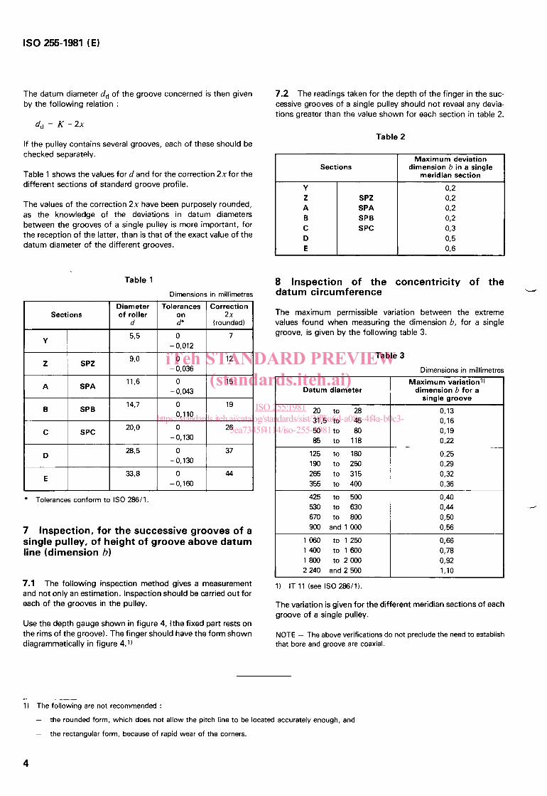
The datum diameter dd of the groove concerned is then given by the following relation :
Tolerances Correction on 2 x d" (rounded)
7.2 The readings taken for the depth of the finger in the suc- cessive grooves of a single pulley should not reveal any devia- tions greater than the value shown for each section in table 2.
Table 2 If the pulley contains several grooves, each of these should be checked separately.
Table 1 shows the values f o r d and for the correction 2xfor the different sections of standard groove profile.
The values of the correction 2x have been purposely rounded, as the knowledge of the deviations in datum diameters between the grooves of a single pulley is more important, for the reception of the latter, than is that of the exact value of the datum diameter of the different grooves.
Tolerances conform to IS0 286/1.
7 Inspection, for the successive grooves of a single pulley, of height of groove above datum line (dimension b)
7.1 The following inspection method gives a measurement and not only an estimation. Inspection should be carried out for each of the grooves in the pulley.
Use the depth gauge shown in figure 4, (the fixed part rests on the rims of the groove). The finger should have the form shown diagrammatically in figure 4.1)
Sections
SPZ SPA SPB SPC
Maximum deviation dimension b in a single
meridian section
8 Inspection of the concentricity of the datum circumference W
The maximum permissible variation between the extreme values found when measuring the dimension b, for a single groove, is given by the following table 3.
Table 3 Dimensions in millimetres
Datum diameter
20 to 28 31.5 to 45 50 to 80 85 to 118
125 to 180 190 to 250 265 to 315 355 to -400
425 to 500 530 to 630 670 to 800 900 and 1 000
1060 to 1250 1400 to1600 1800 to2000 2240 and 2500
Maximum variation11 dimension b for a
single groove O, 13 0.16 O, 19 0.22 0,25 0,29 0 . 3 0,36
0,66 0,78 0,92 1,lO
1) IT 1 1 (see IS0 286/1).
The variation is given for the different meridian sections of each groove of a single pulley.
NOTE - The above verifications do not preclude the need to establish that bore and groove are coaxial.
1 i The following are not recommended : -
-
the rounded form, which does not allow the pitch line to be located accurately enough, and
the rectangular form, because of rapid wear of the corners.
4
iTeh STANDARD PREVIEW(standards.iteh.ai)
ISO 255:1981https://standards.iteh.ai/catalog/standards/sist/3fff6a6d-a08a-4f4a-b0c3-
5ea7345f4114/iso-255-1981

iTeh STANDARD PREVIEW(standards.iteh.ai)
ISO 255:1981https://standards.iteh.ai/catalog/standards/sist/3fff6a6d-a08a-4f4a-b0c3-
5ea7345f4114/iso-255-1981