INTERNATIONAL IEC STANDARD 62196-1 - inmetro.gov.brpontofocal... · INTERNATIONAL STANDARD IEC...
78
INTERNATIONAL STANDARD IEC 62196-1 First edition 2003-04 Plugs, socket-outlets, vehicle couplers and vehicle inlets – Conductive charging of electric vehicles – Part 1: Charging of electric vehicles up to 250 A a.c. and 400 A d.c. Fiches, socles de prise de courant, prises mobiles et socles de connecteur pour véhicule – Charge conductive des véhicules électriques – Partie 1: Charge des véhicules électriques jusqu'à 250 A c.a. et 400 A c.c. Reference number IEC 62196-1:2003(E)
Transcript of INTERNATIONAL IEC STANDARD 62196-1 - inmetro.gov.brpontofocal... · INTERNATIONAL STANDARD IEC...
INTERNATIONALSTANDARD
IEC62196-1
First edition2003-04
Plugs, socket-outlets, vehicle couplersand vehicle inlets –Conductive charging of electric vehicles –
Part 1:Charging of electric vehicles up to 250 A a.c.and 400 A d.c.
Fiches, socles de prise de courant, prises mobileset socles de connecteur pour véhicule –Charge conductive des véhicules électriques –
Partie 1:Charge des véhicules électriques jusqu'à 250 A c.a.et 400 A c.c.
Reference numberIEC 62196-1:2003(E)

Publication numbering
As from 1 January 1997 all IEC publications are issued with a designation in the60000 series. For example, IEC 34-1 is now referred to as IEC 60034-1.
Consolidated editions
The IEC is now publishing consolidated versions of its publications. For example,edition numbers 1.0, 1.1 and 1.2 refer, respectively, to the base publication, thebase publication incorporating amendment 1 and the base publication incorporatingamendments 1 and 2.
Further information on IEC publications
The technical content of IEC publications is kept under constant review by the IEC,thus ensuring that the content reflects current technology. Information relating tothis publication, including its validity, is available in the IEC Catalogue ofpublications (see below) in addition to new editions, amendments and corrigenda.Information on the subjects under consideration and work in progress undertakenby the technical committee which has prepared this publication, as well as the listof publications issued, is also available from the following:
• IEC Web Site (www.iec.ch)
• Catalogue of IEC publications
The on-line catalogue on the IEC web site (http://www.iec.ch/searchpub/cur_fut.htm)enables you to search by a variety of criteria including text searches, technicalcommittees and date of publication. On-line information is also available onrecently issued publications, withdrawn and replaced publications, as well ascorrigenda.
• IEC Just Published This summary of recently issued publications (http://www.iec.ch/online_news/justpub/jp_entry.htm) is also available by email. Please contact the CustomerService Centre (see below) for further information.
• Customer Service Centre
If you have any questions regarding this publication or need further assistance,please contact the Customer Service Centre:
Email: [email protected]: +41 22 919 02 11Fax: +41 22 919 03 00
INTERNATIONALSTANDARD
IEC62196-1
First edition2003-04
Plugs, socket-outlets, vehicle couplersand vehicle inlets –Conductive charging of electric vehicles –
Part 1:Charging of electric vehicles up to 250 A a.c.and 400 A d.c.
Fiches, socles de prise de courant, prises mobileset socles de connecteur pour véhicule –Charge conductive des véhicules électriques –
Partie 1:Charge des véhicules électriques jusqu'à 250 A c.a.et 400 A c.c.
IEC 2003 Copyright - all rights reserved
No part of this publication may be reproduced or utilized in any form or by any means, electronic ormechanical, including photocopying and microfilm, without permission in writing from the publisher.
International Electrotechnical Commission, 3, rue de Varembé, PO Box 131, CH-1211 Geneva 20, SwitzerlandTelephone: +41 22 919 02 11 Telefax: +41 22 919 03 00 E-mail: [email protected] Web: www.iec.ch
XBFor price, see current catalogue
PRICE CODECommission Electrotechnique InternationaleInternational Electrotechnical CommissionМеждународная Электротехническая Комиссия

– 2 – 62196-1 IEC:2003(E)
CONTENTS
FOREWORD .......................................................................................................................... 4INTRODUCTION .................................................................................................................... 5
1 Scope .............................................................................................................................. 62 Normative references....................................................................................................... 83 Definitions ....................................................................................................................... 94 General ..........................................................................................................................135 Ratings ...........................................................................................................................146 Connection between the power supply and the electric vehicle .......................................147 Classification ..................................................................................................................178 Marking ..........................................................................................................................189 Dimensions.....................................................................................................................2010 Protection against electric shock.....................................................................................2011 Size and colour of earthing conductors ...........................................................................2112 Provision for earthing......................................................................................................2113 Terminals........................................................................................................................2314 Interlocks........................................................................................................................2815 Resistance to ageing of rubber and thermoplastic material .............................................2816 General construction.......................................................................................................2817 Construction of socket-outlets.........................................................................................3118 Construction of plugs and vehicle connectors .................................................................3219 Construction of vehicle inlets ..........................................................................................3220 Degrees of protection .....................................................................................................3321 Insulation resistance and dielectric strength....................................................................3422 Breaking capacity ...........................................................................................................3623 Normal operation ............................................................................................................3724 Temperature rise ............................................................................................................3825 Flexible cables and their connection ...............................................................................3926 Mechanical strength........................................................................................................4127 Screws, current-carrying parts and connections ..............................................................4428 Creepage distances, clearances and distances...............................................................4729 Resistance to heat, fire and tracking ...............................................................................4830 Corrosion and resistance to rusting.................................................................................5031 Conditional short-circuit current withstand test ................................................................5132 Electromagnetic compatibility..........................................................................................5233 Vehicle driveover ............................................................................................................53
Annex A (informative) EV charging.......................................................................................70Bibliography ..........................................................................................................................71
62196-1 IEC:2003(E) – 3 –
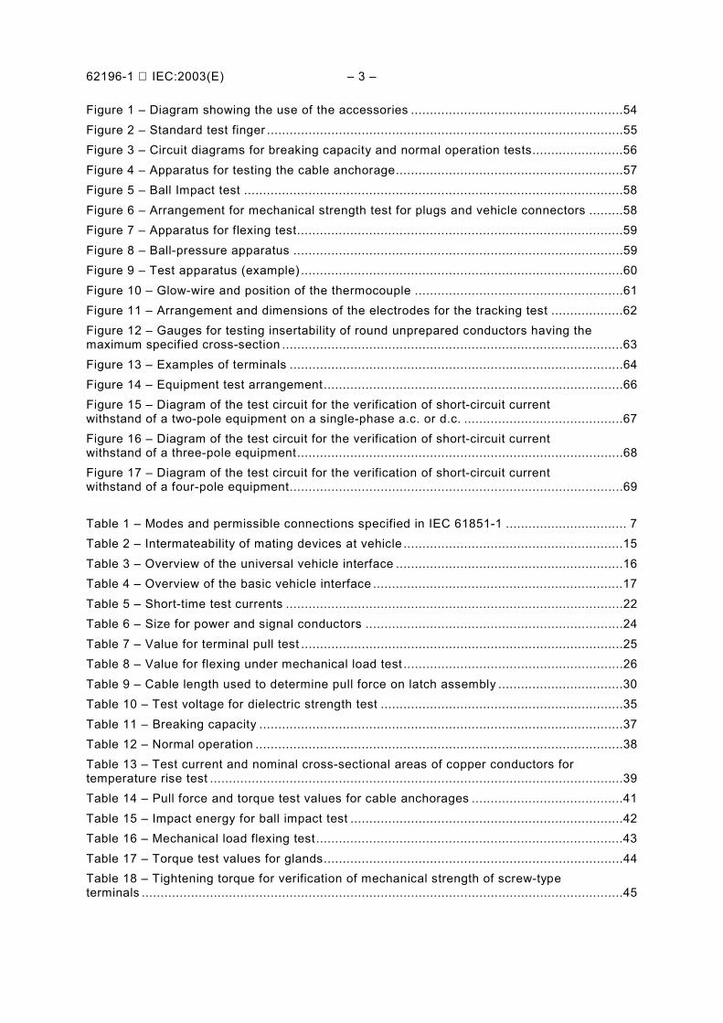
Figure 1 – Diagram showing the use of the accessories ........................................................54Figure 2 – Standard test finger ..............................................................................................55Figure 3 – Circuit diagrams for breaking capacity and normal operation tests........................56Figure 4 – Apparatus for testing the cable anchorage............................................................57Figure 5 – Ball Impact test ....................................................................................................58Figure 6 – Arrangement for mechanical strength test for plugs and vehicle connectors .........58Figure 7 – Apparatus for flexing test......................................................................................59Figure 8 – Ball-pressure apparatus .......................................................................................59Figure 9 – Test apparatus (example) .....................................................................................60Figure 10 – Glow-wire and position of the thermocouple .......................................................61Figure 11 – Arrangement and dimensions of the electrodes for the tracking test ...................62Figure 12 – Gauges for testing insertability of round unprepared conductors having themaximum specified cross-section ..........................................................................................63Figure 13 – Examples of terminals ........................................................................................64Figure 14 – Equipment test arrangement...............................................................................66Figure 15 – Diagram of the test circuit for the verification of short-circuit currentwithstand of a two-pole equipment on a single-phase a.c. or d.c. ..........................................67Figure 16 – Diagram of the test circuit for the verification of short-circuit currentwithstand of a three-pole equipment......................................................................................68Figure 17 – Diagram of the test circuit for the verification of short-circuit currentwithstand of a four-pole equipment........................................................................................69
Table 1 – Modes and permissible connections specified in IEC 61851-1 ................................ 7Table 2 – Intermateability of mating devices at vehicle ..........................................................15Table 3 – Overview of the universal vehicle interface ............................................................16Table 4 – Overview of the basic vehicle interface ..................................................................17Table 5 – Short-time test currents .........................................................................................22Table 6 – Size for power and signal conductors ....................................................................24Table 7 – Value for terminal pull test .....................................................................................25Table 8 – Value for flexing under mechanical load test ..........................................................26Table 9 – Cable length used to determine pull force on latch assembly .................................30Table 10 – Test voltage for dielectric strength test ................................................................35Table 11 – Breaking capacity ................................................................................................37Table 12 – Normal operation .................................................................................................38Table 13 – Test current and nominal cross-sectional areas of copper conductors fortemperature rise test .............................................................................................................39Table 14 – Pull force and torque test values for cable anchorages ........................................41Table 15 – Impact energy for ball impact test ........................................................................42Table 16 – Mechanical load flexing test.................................................................................43Table 17 – Torque test values for glands...............................................................................44Table 18 – Tightening torque for verification of mechanical strength of screw-typeterminals ...............................................................................................................................45
– 4 – 62196-1 IEC:2003(E)
INTERNATIONAL ELECTROTECHNICAL COMMISSION_________
PLUGS, SOCKET-OUTLETS, VEHICLE COUPLERS AND VEHICLE INLETS –CONDUCTIVE CHARGING OF ELECTRIC VEHICLES –
Part 1: Charging of electric vehicles up to 250 A a.c.and 400 A d.c.
FOREWORD1) The IEC (International Electrotechnical Commission) is a worldwide organisation for standardisation comprising
all national electrotechnical committees (IEC National Committees). The object of the IEC is to promoteinternational co-operation on all questions concerning standardisation in the electrical and electronic fields. Tothis end and in addition to other activities, the IEC publishes International Standards. Their preparation isentrusted to technical committees; any IEC National Committee interested in the subject dealt with mayparticipate in this preparatory work. International, governmental and nongovernmental organisations liasing withthe IEC also participate in this preparation. The IEC collaborates closely with the International Organisation forStandardisation (ISO) in accordance with conditions determined by agreement between the two organisations.
2) The formal decisions or agreements of the IEC on technical matters express, as nearly as possible, aninternational consensus of opinion on the relevant subjects since each technical committee has representationfrom all interested National Committees.
3) The documents produced have the form of recommendations for international use and are published in the formof standards, technical specifications, technical reports or guides and they are accepted by the NationalCommittees in that sense.
4) In order to promote international unification, IEC National Committees undertake to apply IEC InternationalStandards transparently to the maximum extent possible in their national and regional standards. Anydivergence between the IEC Standard and the corresponding national or regional standard shall be clearlyindicated in the latter.
5) The IEC provides no marking procedure to indicate its approval and cannot be rendered responsible for anyequipment declared to be in conformity with one of its standards.
6) Attention is drawn to the possibility that some of the elements of this International Standard may be the subjectof patent rights. The IEC shall not be held responsible for identifying any or all such patent rights.
International Standard IEC 62196-1 has been prepared by IEC subcommittee 23H: Industrialplugs and socket-outlets, of IEC technical committee 23: Electrical accessories.
The text of this standard is based on the following documents:
FDIS Report on voting
23H/132/FDIS 23H/135/RVD
Full information on the voting for the approval of this standard can be found in the report onvoting indicated in the above table.
This publication has been drafted in accordance with the ISO/IEC Directives, Part 2.
The committee has decided that the contents of this publication will remain unchanged until2006. At this date, the publication will be
• reconfirmed;• withdrawn;• replaced by a revised edition, or• amended.
A bilingual edition of this standard may be issued at a later date.
62196-1 IEC:2003(E) – 5 –
INTRODUCTION
IEC 61851-1 specifies electric vehicle conductive charging equipment. This InternationalStandard, referred to as the IEC 60309 series in IEC 61851-1, specifies the requirements forplugs, socket-outlets, connectors, inlets and cable assemblies as described in IEC 61851-1.Some charging can be achieved by direct connection from an electric vehicle to commonmains socket outlets. Some modes of charging require a dedicated supply and chargingequipment incorporating control and communication circuits. This standard covers themechanical, electrical and performance requirements for dedicated plugs, socket outlets,vehicle connectors and vehicle inlets for interfacing between such dedicated chargingequipment and the electric vehicle.
This International Standard may be published in several parts, as necessary, including thisPart 1, comprising clauses of a general character, and subsequent parts, presenting particularrequirements for individual types.

– 6 – 62196-1 IEC:2003(E)
PLUGS, SOCKET-OUTLETS, VEHICLE COUPLERS AND VEHICLE INLETS –CONDUCTIVE CHARGING OF ELECTRIC VEHICLES –
Part 1: Charging of electric vehicles up to 250 A a.c.and 400 A d.c.
1 Scope
This part of IEC 62196 is applicable to plugs, socket-outlets, connectors, inlets and cableassemblies for electric vehicles, intended for use in conductive charging systems whichincorporate control means, with a rated operating voltage not exceeding:
– 690 V a.c., 50 – 60 Hz, at a rated current not exceeding 250 A;– 600 V d.c., at a rated current not exceeding 400 A.
These accessories and cable assemblies are intended to be used for circuits specified inIEC 61851-1 which operate at different voltages and frequencies and which may include ELVand communication signals.
These accessories and cable assemblies are to be used in an ambient temperature ofbetween –30 °C and +50 °C. In some countries, other requirements may apply.
These accessories are intended to be connected only to cables with copper or copper-alloyconductors.
The accessories covered by this standard are for use in certain modes of charging EV’s.These modes are defined in IEC 61851-1. These definitions and a description of the types ofconnection (cases A, B and C), also described in IEC 61851-1, are reproduced herein asAnnex A.
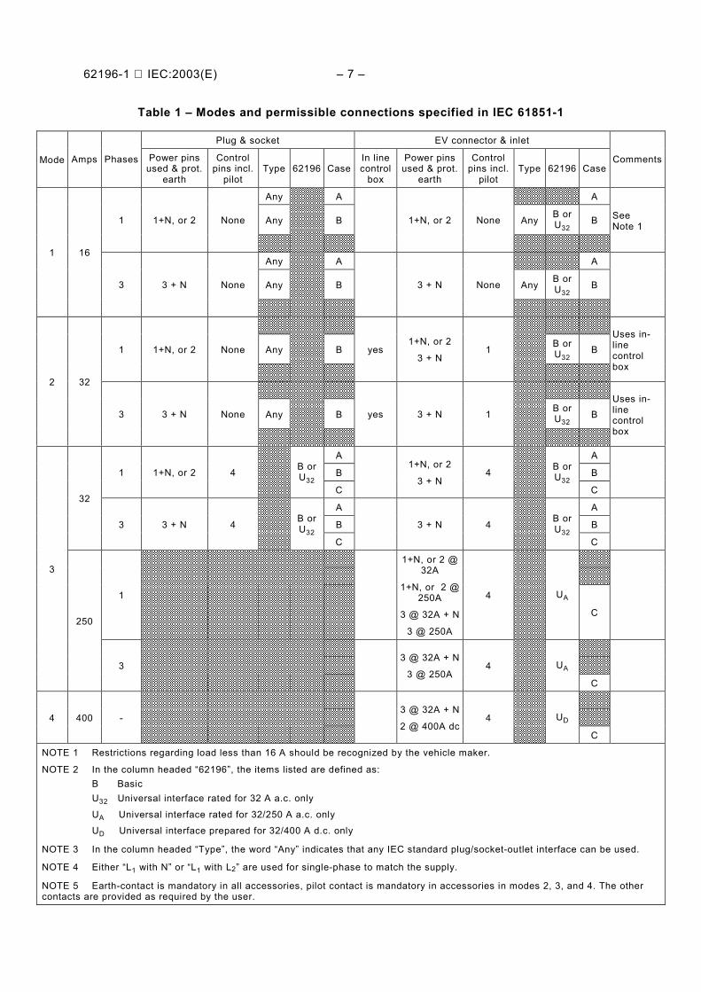
Table 1 illustrates the types of accessories (B, U32, UA, UD) permitted for each chargingsituation (mode and case) and identifies where it is mandatory to use the accessories coveredby this standard. These are indicated by the entries in the columns headed “62196” inTable 1.
The table also describes situations in which either an accessory covered by this standard, orother standardized accessories, are permitted to be used. They are identified by an entry inthe column headed “62196” and the word “Any” under the column headed “Type”.
This standard does not apply to those standardised accessories used in charging systemswhere the use of such accessories constructed to the requirements of other standards ispermitted (e.g. in mode 1 and mode 2). Such standardized accessories may be used for thosesituations (mode and case) identified in Table 1 by the word “Any” under the column headed“Type” and with no corresponding entry under the column headed “62196”.
This standard can be used as a guide for accessories with a lesser number of contacts andlower ratings for use with light duty vehicles.
62196-1 IEC:2003(E) – 7 –
Table 1 – Modes and permissible connections specified in IEC 61851-1
Plug & socket EV connector & inlet
Mode Amps Phases Power pinsused & prot.
earth
Controlpins incl.
pilotType 62196 Case
In linecontrol
box
Power pinsused & prot.
earth
Controlpins incl.
pilotType 62196 Case
Comments
Any A A
Any B Any B orU32
B1 1+N, or 2 None 1+N, or 2 None SeeNote 1
Any A A
Any B Any B orU32
B
1 16
3 3 + N None 3 + N None
Any B B orU32
B1 1+N, or 2 None yes1+N, or 2
3 + N1
Uses in-linecontrolbox
Any B B orU32
B
2 32
3 3 + N None yes 3 + N 1Uses in-linecontrolbox
A A
B B1 1+N, or 2 4 B orU32
C
1+N, or 2
3 + N4 B or
U32C
A A
B B
32
3 3 + N 4 B orU32
C
3 + N 4 B orU32
C
1
1+N, or 2 @32A
1+N, or 2 @250A
3 @ 32A + N
3 @ 250A
4 UA
C
3
250
33 @ 32A + N
3 @ 250A4 UA
C
4 400 -3 @ 32A + N
2 @ 400A dc4 UD
C
NOTE 1 Restrictions regarding load less than 16 A should be recognized by the vehicle maker.
NOTE 2 In the column headed “62196”, the items listed are defined as:B BasicU32 Universal interface rated for 32 A a.c. only
UA Universal interface rated for 32/250 A a.c. onlyUD Universal interface prepared for 32/400 A d.c. only
NOTE 3 In the column headed “Type”, the word “Any” indicates that any IEC standard plug/socket-outlet interface can be used.
NOTE 4 Either “L1 with N” or “L1 with L2” are used for single-phase to match the supply.
NOTE 5 Earth-contact is mandatory in all accessories, pilot contact is mandatory in accessories in modes 2, 3, and 4. The othercontacts are provided as required by the user.
– 8 – 62196-1 IEC:2003(E)
2 Normative references
The following referenced documents are indispensable for the application of this document.For dated references, only the edition cited applies. For undated references, the latest editionof the referenced document (including any amendments) applies.
IEC 60112, Method for the determination of the proof and the comparative tracking indices ofsolid insulating materials
IEC 60227 (all parts): Polyvinyl chloride insulated cables of rated voltages up to and including450/750 V
IEC 60228:1978, Conductors of insulated cables
IEC 60245-4:1994, Rubber insulated cables – Rated voltages up to and including 450/750 V –Part 4: Cords and flexible cables
IEC 60269-1:1998, Low-voltage fuses – Part 1: General requirements
IEC 60269-2:1986, Low-voltage fuses – Part 2: Supplementary requirements for fuses for useby authorised persons (fuses mainly for industrial application
IEC 60529, Degrees of protection provided by enclosures (IP code)
IEC 60664-1:1992, Insulation coordination for equipment within low-voltage systems – Part 1:Principles, requirements and tests1
IEC 60664-3:1992, Insulation coordination for equipment within low-voltage systems – Part 3:Use of coatings to achieve insulation coordination of printed board assemblies
IEC 60695-2-10, Fire hazard testing – Part 2-10: Glowing/hot-wire based test methods –Glow-wire apparatus and common test procedure
IEC 60999-1:1999, Connecting devices – Electrical copper conductors – Safety requirementsfor screw-type and screwless-type clamping units – Part 1: General requirements andparticular requirements for clamping units for conductors from 0,2 mm2 up to 35 mm2
(included)
IEC 60999-2:1999, Connecting devices – Safety requirements for screw-type and screwless-type clamping units for electrical copper conductors – Part 2: Particular requirements forconductors from 35 mm2 up to 300 mm2
IEC 61851-1:2001, Electric vehicle conductive charging system – Part 1: Generalrequirements
———————1 There exists a consolidated edition 1.2 (2002) including edition 1.0 and its Amendments 1 (2000) and 2 (2002).
62196-1 IEC:2003(E) – 9 –
3 Definitions
For the purpose of this document, the following terms and definitions apply. Additionaldefinitions may be found in IEC 61851-1.
Where the terms voltage and current are used, they imply r.m.s. values, unless otherwisespecified.
Throughout this standard, the word “earthing” is used for “protective earthing”.
NOTE 1 The terms “basic interface” and “universal interface” refer to terms described in IEC 61851–1.
The application of accessories is shown in Figure 1.
NOTE 2 The term “accessory” is used as a generic term covering plugs, socket-outlets, vehicle connectors,vehicle inlets and cable assemblies.
3.1 basic insulationinsulation necessary for the proper functioning of the accessory and for basic protectionagainst electric shock
3.2 cable assemblypiece of equipment which is used to establish the connection between the electric vehicle andthe electric vehicle supply equipment. It may be either fixed to and included in one of thesedevices, or detachable. It includes the flexible cable, the vehicle connector and/or plug thatare required for proper connection
NOTE A cable assembly may include one or more cables, with or without a fixed jacket, which may be ina flexible tube, conduit or wire way.
3.3 cable management systemdevice which is intended to protect a cable assembly from mechanical damage and/or tofacilitate its handling
NOTE A cable suspension device is an example of a cable management system.
3.4 cappart separated or attached, which may be used to provide the degree of protection of a plugor vehicle inlet, when it is not engaged with a socket-outlet or connector
3.5 clamping unitpart of a terminal necessary for the clamping and the electrical connection of the conductor
3.6 conditional short-circuit currentprospective current that an accessory, protected by a specified short-circuit protective device,can withstand satisfactorily for the total operating time of that device under specifiedconditions of use and behaviour
NOTE This definition differs from IEV 441-17-20 by broadening the concept of current-limiting device intoa short-circuit protective device, the function of which is not only to limit the current.
– 10 – 62196-1 IEC:2003(E)
3.7 connectiona single conductive path
3.8 covermeans providing the degree of protection of an accessory when it is not engaged with asocket-outlet or vehicle connector. It can be used as the retaining means or a part of theretaining means
NOTE Caps, lids, shutters and similar devices can perform the function of a cover.
3.9 domesticintended for household and similar purposes, up to a maximum current rating of 30 – 32 A a.c.
3.10 double insulationinsulation comprising both basic insulation and supplementary insulation.
3.11 electric vehicle (EV)any vehicle propelled by an electric motor drawing current from a rechargeable storagebattery or from other portable energy storage devices (rechargeable using energy from asource off the vehicle such as residential or public electric service), which is manufacturedprimarily for use on public streets, roads or highways
3.12 in-cable control boxdevice which is incorporated in the cable assembly and which performs control functions. It islocated within the plug or within 0,3 m of the plug or the electric vehicle supply equipment
3.13 insulation voltagethe voltage assigned to the accessory by the manufacturer and to which dielectric tests,clearances and creepage distances are referred
3.14 integral switching devicemechanical switching device constructed as a part of an accessory covered by this standard
3.15 interlockdevice, either electrical or mechanical, which prevents the contacts of a socket-outlet frombecoming live before it is in proper engagement with a plug, and which either prevents theplug from being withdrawn while its contacts are live or makes the contacts dead beforeseparation
3.16 intermateabilitythe ability of like accessories to join together with the mating accessories they are intended tobe used with
3.17 lida means to ensure the degree of protection on a socket-outlet or a vehicle connector
62196-1 IEC:2003(E) – 11 –
3.18 mechanical switching deviceswitching device designed to close and open one or more electric circuits by means ofseparable contacts
3.19 non-rewireable accessoryaccessory so constructed that the cable or wiring cannot be separated from the accessorywithout making it permanently useless
NOTE A plug which is integrally moulded to the cable is an example of a non-rewireable accessory.
3.20 plug and socket-outleta means enabling the connection at will of a flexible cable to fixed wiring. It consists of twoparts: a socket-outlet and a plug
3.20.1plugthe part of a plug and a socket-outlet integral with or intended to be attached to one flexiblecable connected to the electric vehicle or to a vehicle connector. It may include mechanical,electrical or electronic components and circuitry, which perform control functions
3.20.2socket-outletthe part of a plug and a socket-outlet intended to be installed with the fixed wiring orincorporated in equipment
3.21 rated current(s)current assigned to each pole of the accessory by the manufacturer
3.22 rated operating voltagenominal voltage of the supply(ies) for which the pole of the accessory is intended to be used
3.23 reinforced insulationan improved basic insulation with such mechanical and electrical qualities that it providesthe same degree of protection against electric shock as double insulation
3.24 retaining meansa mechanical arrangement which holds a plug or vehicle connector in position when it is inproper engagement, and prevents its unintentional withdrawal
3.25 rewireable accessoryaccessory so constructed that the cable or wiring can be replaced. It can be either a user-serviceable accessory or a field-serviceable accessory
3.26 user-serviceable accessoryaccessory so constructed that it can be rewired, or parts can be replaced, using commonlyavailable tools and without having to replace individual parts of the accessory
NOTE An ordinary plug, which can be disassembled and wired using a common screwdriver, is an example ofuser-serviceable accessory.
– 12 – 62196-1 IEC:2003(E)
3.27 field-serviceable accessoryaccessory so constructed that it shall only be rewired by the manufacturer’s authorisedpersonnel
3.28 switched socket-outletsocket-outlet with an associated switching device to disconnect the supply from the socket-outlet contacts
3.29 supplementary insulation (protective insulation)independent insulation provided in addition to the basic insulation, in order to ensureprotection against electric shock in the event of a failure of the basic insulation
3.30 terminalconductive part provided for the connection of a conductor to an accessory
3.30.1pillar terminalterminal in which the conductor is inserted into a hole or cavity, where it is clamped under theshank of the screw or screws. The clamping pressure may be applied directly by the shank ofthe screw or through an intermediate clamping member to which pressure is applied by theshank of the screw
NOTE See Figure 13a.
3.30.2screw terminala terminal in which the conductor is clamped under the head of the screw. The clampingpressure may be applied directly by the head of the screw or through an intermediate part,such as a washer, clamping plate or anti-spread device
NOTE See Figures 13b and 13c.
3.30.3stud terminala terminal in which the conductor is clamped under a nut. The clamping pressure may beapplied directly by a suitably shaped nut or through an intermediate part, such as a washer,clamping plate or anti-spread device
NOTE See Figure 13d.
3.30.4saddle terminala terminal in which the conductor is clamped under a saddle by means of two or more screwsor nuts
NOTE See Figure 13e.
3.30.5lug terminala screw terminal or stud terminal designed for clamping a cable lug or bar by means of ascrew or nut
NOTE See Figure 13f.
62196-1 IEC:2003(E) – 13 –
3.30.6mantle terminalterminal in which the conductor is clamped against the base of a slot in a threaded stud bymeans of a nut. The conductor is clamped against the base of the slot by a suitably shapedwasher under the nut, by a central peg if the nut is a cap nut, or by equally effective meansfor transmitting the pressure from the nut to the conductor within the slot
NOTE See Figure 13g.
3.31 vehicle coupler (EV coupler)a means enabling the connection at will of a flexible cable to an electric vehicle. It consists oftwo parts: a vehicle connector and a vehicle inlet
3.31.1vehicle connector (EV connector)the part of a vehicle coupler integral with, or intended to be attached to, one flexible cableconnected to the supply
3.31.2vehicle inlet (EV inlet)the part of a vehicle coupler incorporated in, or fixed to, the electric vehicle
4 General
4.1 General requirements
Accessories shall be so designed and constructed that in normal use their performance isreliable and minimises the risk of danger to the user or surroundings.
Compliance is checked by meeting all of the relevant requirements and tests specified.
4.2 General notes on tests
4.2.1 Tests according to this standard are type tests. If a part of an accessory has previouslypassed tests for a given degree of severity, the relevant type tests shall not be repeated if theseverity is not greater.
4.2.2 Unless otherwise specified, the samples are tested as delivered and under normalconditions of use, at an ambient temperature of (20 ± 5) °C; the tests are made at ratedfrequency.
4.2.3 Unless otherwise specified, the tests are carried out in the order of the clauses of thisstandard.
4.2.4 Three samples are subjected to all the tests, except if necessary for the test of Clause30, one new additional sample is tested. If, however, the tests of Clauses 21, 22 and 23 haveto be made with both d.c. and a.c., the tests with a.c. in Clauses 21, 22 and 23 are made onthree additional samples. For the tests of Clauses 21.3 and 33, three new samples are to beused.
– 14 – 62196-1 IEC:2003(E)
4.2.5 Accessories are deemed to comply with this standard if no sample fails in the completeseries of appropriate tests. If one sample fails in a test, that test and those preceding whichmay have influenced the test result are repeated on another set of three samples, all of whichshall then pass the repeated tests.
NOTE In general, it will only be necessary to repeat the test which caused the failure, unless the sample fails inone of the tests of Clauses 22 and 23, in which case the tests are repeated from that of Clause 21 onwards.
The applicant may submit, together with the first set of samples, the additional set which may be wanted shouldone sample fail. The testing station, without further request, will then test the additional samples and will rejectonly if a further failure occurs. If the additional set of samples is not submitted at the same time, the failure of onesample will entail a rejection.
4.2.6 When the tests are carried out with conductors, they shall be copper and comply withIEC 60227, IEC 60228 [Clause 2, solid (class 1), stranded (class 2), flexible (class 5 and 6)],and IEC 60245-4 as accessories according to this standard are intended to be connected tocables with copper or copper-alloy conductors only.
5 Ratings
5.1 Preferred rated operating voltages:
0 to 30 V (signal or control purposes only);230 V a.c.400 V a.c.500 V a.c.600 V d.c.
5.2 Rated currents:
30 A a.c. or 32 A a.c., 250 A a.c., 400 A d.c.NOTE 1 In the following countries the branch circuit overcurrent protection device is based upon 125 % of theaccessory rating: USA.
NOTE 2 Throughout this standard, reference to a 30 A or 32 A rating is made in accordance with nationalrequirements.
5.3 Rated current for signal or control purposes: 2 A
5.4 An accessory rated 250 A a.c. or 400 A d.c. shall be rated for disconnecting use only,not for current interruption.
5.5 An accessory, rated 32 A, with a pilot circuit contact may be rated as suitable for or notsuitable for making and breaking an electrical circuit. See 7.1.4.
6 Connection between the power supply and the electric vehicle
6.1 This section provides a description of the physical conductive electrical interfacerequirements between the vehicle and the power supply, which allows two designs at thevehicle interface:
a) a universal interface for all modes of charging which provides for either:1) high power a.c. and 32 A a.c., or2) high power d.c. and 32 A a.c. power;
b) a basic interface for mode 1, 2 and 3 charging only, which provides for 32 A a.c.
62196-1 IEC:2003(E) – 15 –
6.2 There shall be three types of vehicle inlets, each identified by the marking specifiedin 8.2:
universal, high power a.c. (UA)
universal, high power d.c. (UD)
basic (B)
6.3 There shall be four types of vehicle connectors, each identified by the marking specifiedin Clause 8.2:
universal, high power a.c. (UA)
universal, high power d.c. (UD)
universal, 32 A a.c. (U32)
basic (B)
NOTE The letters UA, UD, U32 and B have been chosen to correlate with the terms “universal”, “a.c. high power”,d.c. high power”, “low power” and “basic”, as used in IEC 61851-1.
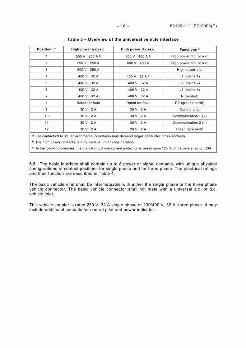
6.4 The universal interface shall contain up to 12 power or signal contacts, with only onephysical configuration of contact positions. These positions may be used or not, according tothe mode of charging of the vehicle. The electrical ratings and their function are described inTable 3.
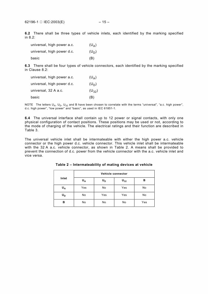
The universal vehicle inlet shall be intermateable with either the high power a.c. vehicleconnector or the high power d.c. vehicle connector. This vehicle inlet shall be intermateablewith the 32 A a.c. vehicle connector, as shown in Table 2. A means shall be provided toprevent the connection of d.c. power from the vehicle connector with the a.c. vehicle inlet andvice versa.
Table 2 – Intermateability of mating devices at vehicle
Vehicle connectorInlet
UA UD U32 B
UA Yes No Yes No
UD No Yes Yes No
B No No No Yes
– 16 – 62196-1 IEC:2003(E)
Table 3 – Overview of the universal vehicle interface
Position n° High power a.c./a.c. High power d.c./a.c. Functions a
1 500 V 250 A b 600 V 400 A b High power d.c. or a.c.
2 500 V 250 A 600 V 400 A High power d.c. or a.c.
3 500 V 250 A – High power a.c.
4 400 V 32 A 400 V 32 A c L1 (mains 1)
5 400 V 32 A 400 V 32 A L2 (mains 2)
6 400 V 32 A 400 V 32 A L3 (mains 3)
7 400 V 32 A 400 V 32 A N (neutral)
8 Rated for fault Rated for fault PE (ground/earth)
9 30 V 2 A 30 V 2 A Control pilot
10 30 V 2 A 30 V 2 A Communication 1 (+)
11 30 V 2 A 30 V 2 A Communication 2 (–)
12 30 V 2 A 30 V 2 A Clean data earth
a For contacts 9 to 12, environmental conditions may demand larger conductor cross-sections.b For high power contacts, a duty cycle is under consideration.c In the following countries, the branch circuit overcurrent protection is based upon 125 % of the device rating: USA.
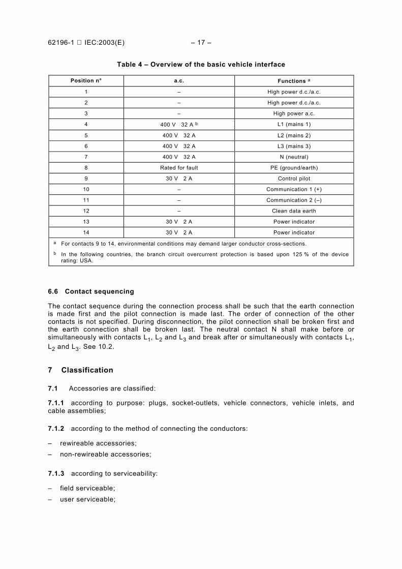
6.5 The basic interface shall contain up to 8 power or signal contacts, with unique physicalconfigurations of contact positions for single phase and for three phase. The electrical ratingsand their function are described in Table 4.
The basic vehicle inlet shall be intermateable with either the single phase or the three phasevehicle connector. The basic vehicle connector shall not mate with a universal a.c. or d.c.vehicle inlet.
This vehicle coupler is rated 230 V, 32 A single phase or 230/400 V, 32 A, three phase. It mayinclude additional contacts for control pilot and power indicator.
62196-1 IEC:2003(E) – 17 –
Table 4 – Overview of the basic vehicle interface
Position n° a.c. Functions a
1 – High power d.c./a.c.
2 – High power d.c./a.c.
3 – High power a.c.
4 400 V 32 A b L1 (mains 1)
5 400 V 32 A L2 (mains 2)
6 400 V 32 A L3 (mains 3)
7 400 V 32 A N (neutral)
8 Rated for fault PE (ground/earth)
9 30 V 2 A Control pilot
10 – Communication 1 (+)
11 – Communication 2 (–)
12 – Clean data earth
13 30 V 2 A Power indicator
14 30 V 2 A Power indicator
a For contacts 9 to 14, environmental conditions may demand larger conductor cross-sections.b In the following countries, the branch circuit overcurrent protection is based upon 125 % of the device
rating: USA.
6.6 Contact sequencing
The contact sequence during the connection process shall be such that the earth connectionis made first and the pilot connection is made last. The order of connection of the othercontacts is not specified. During disconnection, the pilot connection shall be broken first andthe earth connection shall be broken last. The neutral contact N shall make before orsimultaneously with contacts L1, L2 and L3 and break after or simultaneously with contacts L1,L2 and L3. See 10.2.
7 Classification
7.1 Accessories are classified:
7.1.1 according to purpose: plugs, socket-outlets, vehicle connectors, vehicle inlets, andcable assemblies;
7.1.2 according to the method of connecting the conductors:
– rewireable accessories;– non-rewireable accessories;
7.1.3 according to serviceability:
– field serviceable;– user serviceable;
– 18 – 62196-1 IEC:2003(E)
7.1.4 according to electrical operation:– suitable for making and breaking an electrical circuit under load;– not suitable for making and breaking an electrical circuit under load;
7.1.5 according to function as specified in Clause 6:– basic;– universal high power a.c.;– universal high power d.c.;– universal 32;
7.1.6 according to use with cable management systems.
(Under future consideration)
8 Marking
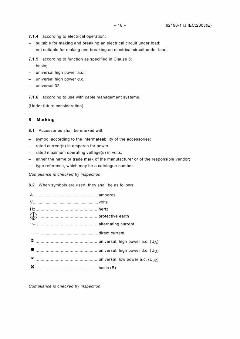
8.1 Accessories shall be marked with:
– symbol according to the intermateability of the accessories;– rated current(s) in amperes for power;– rated maximum operating voltage(s) in volts;– either the name or trade mark of the manufacturer or of the responsible vendor;– type reference, which may be a catalogue number.
Compliance is checked by inspection.
8.2 When symbols are used, they shall be as follows:
A........................................................ amperes
V........................................................ volts
Hz ..................................................hertz
...............................................protective earth
.................................................alternating current
................................................. direct current
vvvv ..................................................universal, high power a.c. (UA)
nnnn ..................................................universal, high power d.c. (UD)
uuuu ..................................................universal, low power a.c. (U32)
rrrr ..................................................basic (B)
Compliance is checked by inspection.
62196-1 IEC:2003(E) – 19 –
8.3 For all accessories, the marking for the intermateability symbol shall be on the outside ofmain part, visible to the user during use. For plugs and vehicle connectors, the marking foreither the name or trade mark of the manufacturer or the responsible vendor and the typereference, catalogue number or designation shall also be on the outside of the accessory,visible to the user.
8.4 The intermateability symbol shall be at least 10 mm in height and prominent, may be incontrasting colour, and may be provided on a pressure sensitive label or similar means whichcan be attached to the vehicle inlet cover and connector.
Compliance is checked by inspection.
8.5 For all accessories, the marking for the maximum rated operating voltage and ratedcurrent shall be on a place which is visible before installation of the accessory. For socket-outlets and vehicle inlets, the marking for either the name or trademark of the manufacturer orthe responsible vendor and the type reference, catalogue number or designation shall be on aplace which is visible before installation of the accessory. It need not be visible afterinstallation.
Compliance is checked by inspection.
8.6 For rewireable accessories, the contacts shall be indicated by the position numbers 1 to12 as indicated in Table 3, or position numbers 4 to 14 as indicated in Table 4.
These position numbers shall be placed close to the relevant terminals; they shall not beplaced on screws, removable washers or other removable parts.
Compliance is checked by inspection.
8.7 For rewireable accessories, wiring instructions shall be provided.
Compliance is checked by inspection.
8.8 For non-rewireable accessories, the markings in Clauses 8.6 and 8.7 are not required.
8.9 Marking shall be indelible and easily legible.
Compliance is checked by inspection and by the following test.
After the humidity treatment of 20.3, the marking is rubbed vigorously by hand for 15 s with apiece of cloth soaked in water and again for 15 s with a piece of cloth soaked with petroleumspirit.
NOTE It is recommended that the petroleum spirit used consist of a solvent hexane with an aromatic content ofmaximum 0,1 volume percentage, a kauributanol value of approximately 29, an initial boiling point of approximately65 °C, a dry point of approximately 69 °C, and a density of approximately 0,68 g/cm3.
8.10 Cable assemblies comprised of the cable and one accessory, shall be provided withinformation to identify the wire terminations, terminals, etc, to provide wiring and installationinstructions.
The unwired end of a cable assembly intended for connection to a rewireable accessory shallbe marked to identify the conductors.
– 20 – 62196-1 IEC:2003(E)
9 Dimensions
9.1 EV accessories shall comply with the appropriate standard sheets, if any. If no standardsheet is available, the accessories shall comply with the specifications provided by themanufacturer.
9.2 EV accessories may be compatible only with other standardised EV accessories. It shallnot be possible to engage plugs or vehicle connectors with socket-outlets or vehicle inletshaving different ratings, or having different contact combinations unless safe operation isensured or other means are provided to ensure safe operation.
In addition, the design shall be such that improper connections shall not be possible between:
– signal and control contacts and a live (power) contact;– the earth and/or pilot plug-contact and a live socket-contact, or a live plug-contact and the
earth and/or pilot socket-contact;– the phase plug-contacts and the neutral socket-contact, if any;– a neutral plug-contact and a phase socket-contact.
Compliance is checked by inspection and manual test.
9.3 It shall not be possible to make single-pole connections between plugs and socket-outlets or vehicle connectors, or between vehicle inlets and vehicle connectors or socket-outlets within a single family of accessories.
Compliance is checked by inspection and manual test.
10 Protection against electric shock
10.1 Accessories shall be so designed that live parts of socket-outlets and vehicleconnectors, when they are wired as in normal use, and live parts of plugs and vehicle inlets,when they are in partial or complete engagement with the complementary accessories, arenot accessible.
In addition, it shall not be possible to make contact between a live part of a plug or vehicleinlet and a live part of a socket-outlet or vehicle connector while any live part is accessible.
NOTE Neutral contacts and pilot contacts of socket-outlets and vehicle connectors are deemed to be live parts.Signal, data earth and earth contacts are not considered live parts.
This clause does not apply to contacts and conductors used for signal, data, communicationsand control circuits.
Compliance is checked by inspection and, if necessary, by a test on the sample wired as innormal use.
The standard test finger shown in Figure 2 is applied in every possible position, an electricalindicator, with a voltage not less than 40 V, being used to show contact with the relevant part.
62196-1 IEC:2003(E) – 21 –
10.2 Accessories shall be so designed that:
a) when inserting the plug or vehicle connector,1) the earth connection is made before the phase connections and neutral, if any, are
made;2) the control pilot connection, if any, is made after the phase connections and neutral
are made;b) when withdrawing the plug or vehicle connector,
1) the phase connections and neutral, if any, are broken before the earth connection isbroken;
2) the control pilot connection, if any, is broken before the phase connections and neutralare broken.
Compliance is checked by inspection and manual test, if required.
10.3 It shall not be possible to inadvertently assemble either the part carrying plug or inletcontacts into the enclosure of a socket-outlet or vehicle connector or the part carrying thesocket-outlet or vehicle connector contacts into the enclosure of a plug or inlet.
Compliance is checked by inspection and manual test, if required.
11 Size and colour of earthing conductors
The core connected to the earthing terminal shall be identified by the colour combinationgreen/yellow. The nominal cross-sectional area of the earthing conductor and of the neutralconductor, if any, shall be at least equal to that of the phase conductors, or as specifiedin Table 6.
NOTE In the following countries, the colour green may be used to identify the earthing conductor: JP, USA, CA.
12 Provision for earthing
12.1 Accessories shall be provided with a protective earthing contact and earthing terminal.
Protective earthing contacts shall be directly and reliably connected to the protective earthingterminals.
Compliance is checked by inspection.
12.2 Accessible metal parts of accessories, which may become live in the event of aninsulation fault, shall be reliably connected to the internal earthing terminal(s) by construction.
NOTE 1 For the purpose of this requirement, screws for fixing bases, covers and the like are not deemed to beaccessible parts which may become live in the event of an insulation fault.
If accessible metal parts are screened from live parts by metal parts which are connected to an earthing terminal orearthing contact, or if they are separated from live parts by double insulation or reinforced insulation, they are not,for the purpose of this requirement, regarded as likely to become live in the event of an insulation fault.
Compliance is checked by inspection and by the following test:
A current of 25 A derived from an a.c. source having a no-load voltage not exceeding 12 V ispassed between the earthing terminal and each of the accessible metal parts in turn.
The voltage drop between the earthing terminal and the accessible metal part is measured,and the resistance calculated from the current and this voltage drop.
– 22 – 62196-1 IEC:2003(E)
In no case shall the resistance exceed 0,05 Ω.
NOTE 2 Care should be taken that the contact resistance between the tip of the measuring probe and the metalpart under test does not influence the test results.
12.3 Earthing contacts shall comply with the test requirement in either 12.3.1 or 12.3.2–12.3.4, as specified by the manufacturer.
12.3.1 Earthing contacts shall be capable of carrying a current equal to that specified for thephase contacts without overheating.
Compliance is checked by the test of Clause 24.
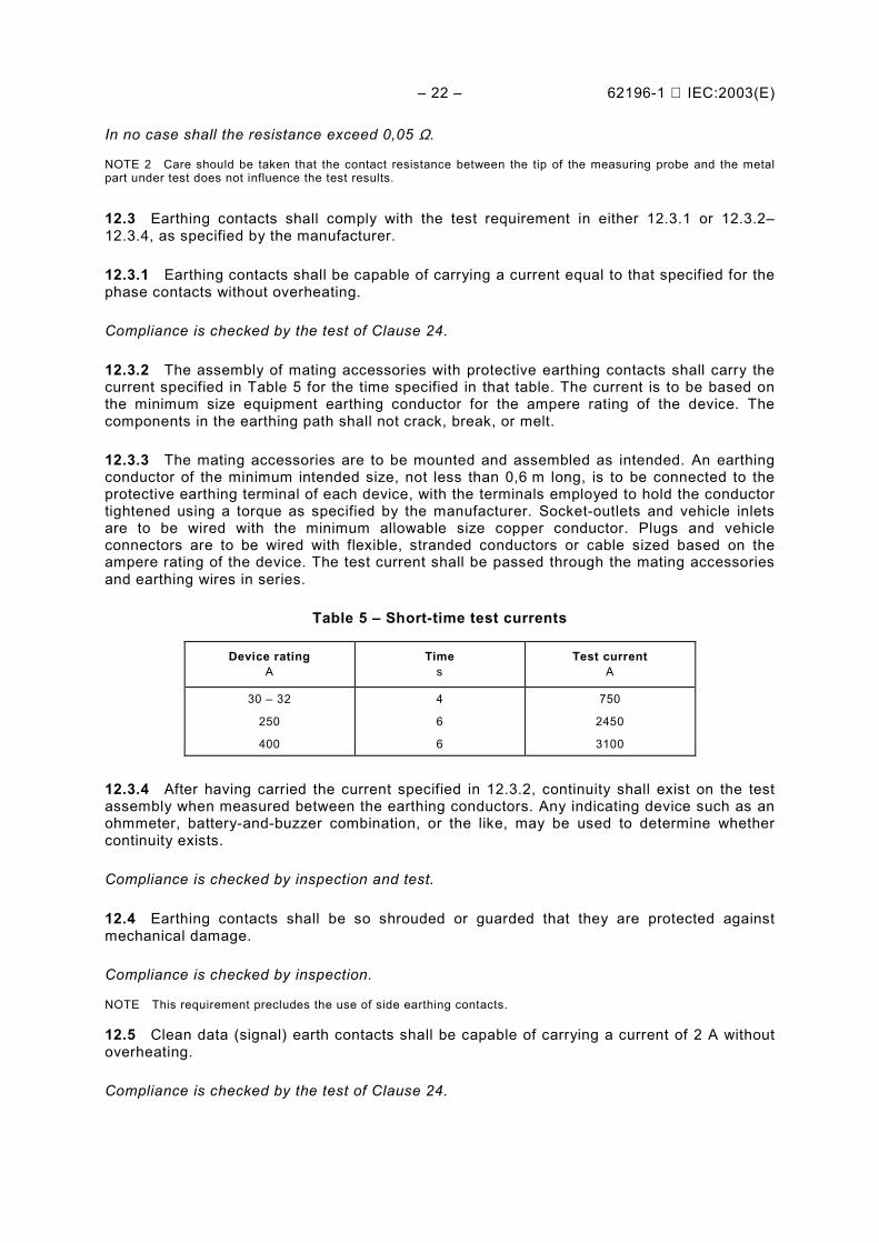
12.3.2 The assembly of mating accessories with protective earthing contacts shall carry thecurrent specified in Table 5 for the time specified in that table. The current is to be based onthe minimum size equipment earthing conductor for the ampere rating of the device. Thecomponents in the earthing path shall not crack, break, or melt.
12.3.3 The mating accessories are to be mounted and assembled as intended. An earthingconductor of the minimum intended size, not less than 0,6 m long, is to be connected to theprotective earthing terminal of each device, with the terminals employed to hold the conductortightened using a torque as specified by the manufacturer. Socket-outlets and vehicle inletsare to be wired with the minimum allowable size copper conductor. Plugs and vehicleconnectors are to be wired with flexible, stranded conductors or cable sized based on theampere rating of the device. The test current shall be passed through the mating accessoriesand earthing wires in series.
Table 5 – Short-time test currents
Device ratingA
Times
Test currentA
30 – 32
250
400
4
6
6
750
2450
3100
12.3.4 After having carried the current specified in 12.3.2, continuity shall exist on the testassembly when measured between the earthing conductors. Any indicating device such as anohmmeter, battery-and-buzzer combination, or the like, may be used to determine whethercontinuity exists.
Compliance is checked by inspection and test.
12.4 Earthing contacts shall be so shrouded or guarded that they are protected againstmechanical damage.
Compliance is checked by inspection.
NOTE This requirement precludes the use of side earthing contacts.
12.5 Clean data (signal) earth contacts shall be capable of carrying a current of 2 A withoutoverheating.
Compliance is checked by the test of Clause 24.
62196-1 IEC:2003(E) – 23 –
13 Terminals
13.1 Connections to terminals of contacts rated 250 A or more shall provide a permanentand secure connection. These terminals shall not be rewireable or user serviceable.
13.2 Rewireable accessories shall be provided with terminals in which connection is madeby means of screws, nuts or equally effective devices.
Compliance is checked by inspection.
13.3 Parts of terminals, other than screws, nuts, washers, stirrups, clamping plates and thelike, shall be either of:
• copper;
• an alloy containing at least 58 % copper for parts that are worked cold or at least 50 %copper for other parts;
• or other metal not less resistant to corrosion than copper and having mechanical andelectrical properties no less suitable.
Steel screws shall be adequately protected against corrosion.
Compliance is checked by inspection and by chemical analysis.
13.4 If the body of an earthing terminal is not part of the metal frame or housing of theaccessory, the body shall be of material as prescribed in 13.3 for parts for terminals. If thebody is part of the metal frame or housing, the clamping screw or nut shall be of suchmaterial.
If the body of the earthing terminal is part of a frame or housing of aluminium or aluminiumalloy, precautions shall be taken to avoid the risk of corrosion resulting from contact betweencopper and aluminium or its alloys.
NOTE The requirement regarding the avoidance of the risk of corrosion does not preclude the use of adequatelycoated metal screws or nuts.
Requirements that are more detailed are under consideration.
Compliance is checked by inspection and by chemical analysis.
NOTE A test for determining the resistance to corrosion is under consideration.
13.5 Terminals shall provide for the connection of copper or copper-alloy conductors. Forrewireable accessories, these terminals shall provide for the connection of conductors havingnominal cross-sectional areas as shown in Table 6. For non-rewireable accessories, theseterminals shall provide for the connection of conductors having nominal cross-sectional areasas specified by the manufacturer of the cable assembly.
For terminals other than lug terminals, compliance is checked by the following test and by thetests of 13.8, 13.9 and 13.10.
Gauges as specified in Figure 12, having a measuring section for testing the insertability ofthe maximum specified cross-sectional area of Table 6 shall be able to penetrate into theterminal aperture under their own weight to the designated depth of the terminal.
– 24 – 62196-1 IEC:2003(E)
For pillar terminals in which the end of a conductor is not visible, the hole to accommodatethe conductor shall have a depth such that the distance between the bottom of the hole andthe last screw will be equal to at least half the diameter of the screw, and in any case not lessthan 1,5 mm.
Compliance is checked by inspection.
For terminals complying with Figure 13f), the lug shall accept conductors having nominalcross-sectional areas within the appropriate range specified in Table 6.
Terminals that cannot be checked by the gauges specified in Figure 12 are tested by suitablyshaped gauges having the same cross-section as those of the appropriate gauges given inFigure 12.
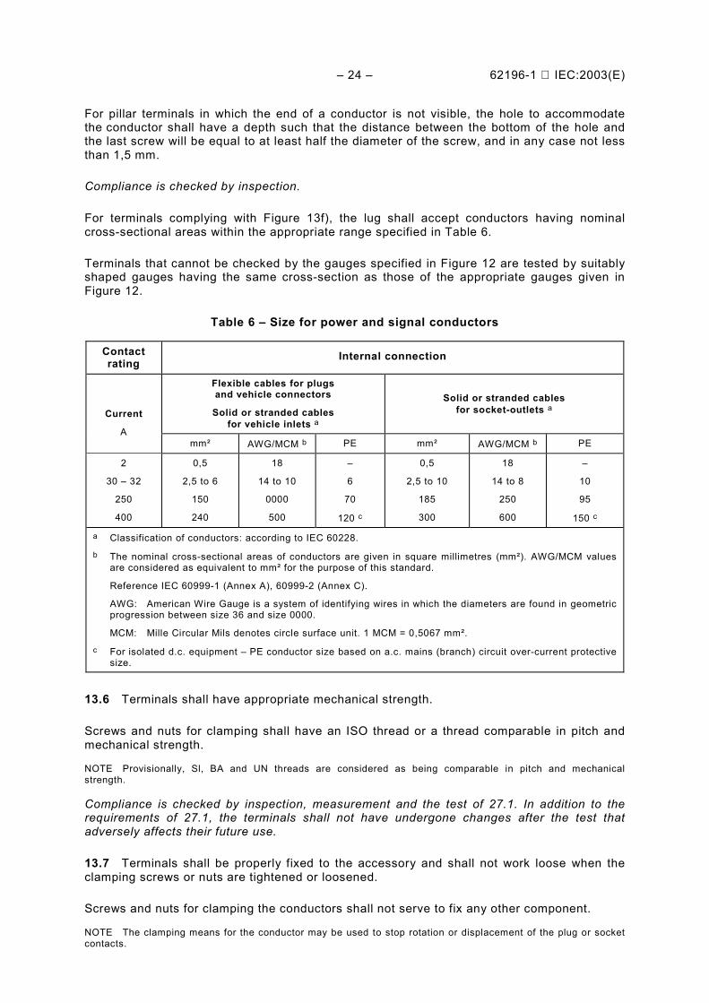
Table 6 – Size for power and signal conductors
Contactrating Internal connection
Flexible cables for plugsand vehicle connectors
Solid or stranded cablesfor vehicle inlets a
Solid or stranded cablesfor socket-outlets aCurrent
Amm² AWG/MCM b PE mm² AWG/MCM b PE
2
30 – 32
250
400
0,5
2,5 to 6
150
240
18
14 to 10
0000
500
–
6
70
120 c
0,5
2,5 to 10
185
300
18
14 to 8
250
600
–
10
95
150 c
a Classification of conductors: according to IEC 60228.b The nominal cross-sectional areas of conductors are given in square millimetres (mm²). AWG/MCM values
are considered as equivalent to mm² for the purpose of this standard.
Reference IEC 60999-1 (Annex A), 60999-2 (Annex C).
AWG: American Wire Gauge is a system of identifying wires in which the diameters are found in geometricprogression between size 36 and size 0000.
MCM: Mille Circular Mils denotes circle surface unit. 1 MCM = 0,5067 mm².c For isolated d.c. equipment – PE conductor size based on a.c. mains (branch) circuit over-current protective
size.
13.6 Terminals shall have appropriate mechanical strength.
Screws and nuts for clamping shall have an ISO thread or a thread comparable in pitch andmechanical strength.
NOTE Provisionally, Sl, BA and UN threads are considered as being comparable in pitch and mechanicalstrength.
Compliance is checked by inspection, measurement and the test of 27.1. In addition to therequirements of 27.1, the terminals shall not have undergone changes after the test thatadversely affects their future use.
13.7 Terminals shall be properly fixed to the accessory and shall not work loose when theclamping screws or nuts are tightened or loosened.
Screws and nuts for clamping the conductors shall not serve to fix any other component.
NOTE The clamping means for the conductor may be used to stop rotation or displacement of the plug or socketcontacts.
62196-1 IEC:2003(E) – 25 –
Compliance is checked by inspection and, if necessary, by the test of 27.1.
NOTE These requirements do not preclude terminals that are floating or terminals so designed that rotation ordisplacement of the terminal is prevented by the clamping screw or nut, if their movement is appropriately limitedand does not impair the correct operation of the accessory.
Terminals may be prevented from working loose by fixing with two screws, by fixing with one screw in a recesssuch that there is no appreciable play or by other suitable means.
Covering with sealing compound without other means of locking is not deemed sufficient. Self-hardening resinsmay, however, be used to lock terminals which are not subject to torsion in normal use.
13.8 Terminals shall be so designed that they clamp the conductor between metal surfaceswith sufficient contact pressure and without damage to the conductor.
Compliance is checked by inspection and the type tests of the terminals of 13.9 and 13.10,applied to three separate terminals.
13.9 First test:
Verification is made successively with conductors of the largest and smallest cross-sectionalareas specified in Table 6, using class 1 or class 2 conductors for terminals of socket-outletsor vehicle inlets and class 5 conductors for terminals of plugs or vehicle connectors.
The conductors shall be connected to the clamping unit, and the clamping screws or nutstightened to two-thirds of the torque indicated in Table 18, unless the torque is specified bythe manufacturer on the product or in an instruction sheet.
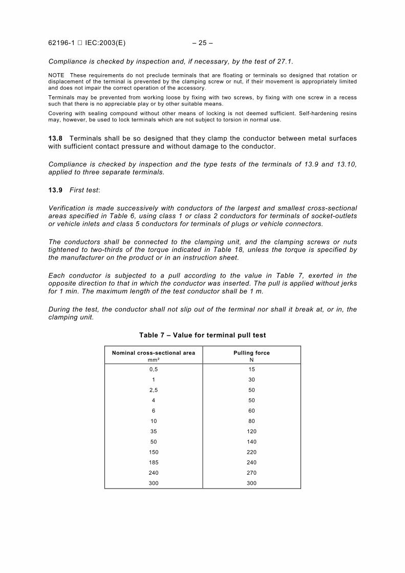
Each conductor is subjected to a pull according to the value in Table 7, exerted in theopposite direction to that in which the conductor was inserted. The pull is applied without jerksfor 1 min. The maximum length of the test conductor shall be 1 m.
During the test, the conductor shall not slip out of the terminal nor shall it break at, or in, theclamping unit.
Table 7 – Value for terminal pull test
Nominal cross-sectional areamm²
Pulling forceN
0,5
1
2,5
4
6
10
35
50
150
185
240
300
15
30
50
50
60
80
120
140
220
240
270
300
– 26 – 62196-1 IEC:2003(E)
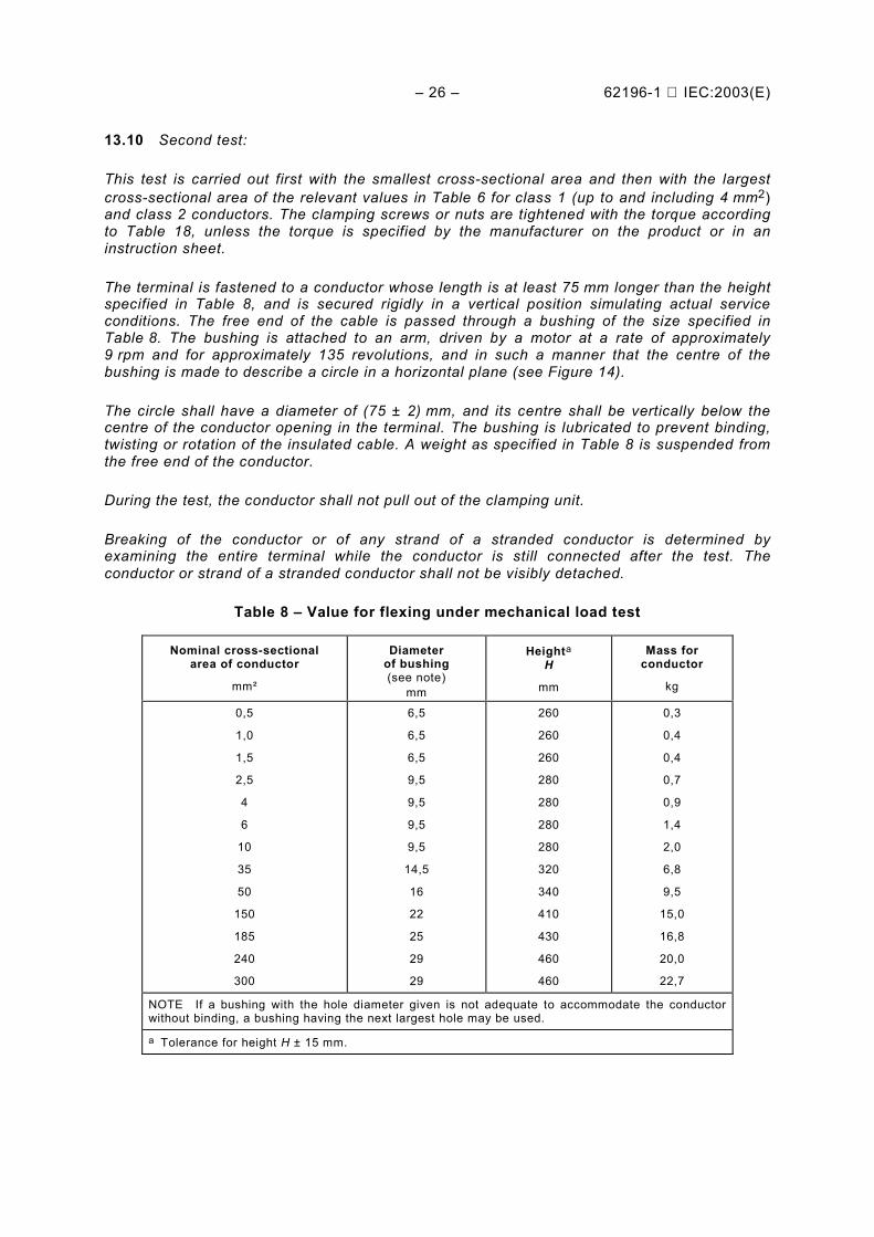
13.10 Second test:
This test is carried out first with the smallest cross-sectional area and then with the largestcross-sectional area of the relevant values in Table 6 for class 1 (up to and including 4 mm2)and class 2 conductors. The clamping screws or nuts are tightened with the torque accordingto Table 18, unless the torque is specified by the manufacturer on the product or in aninstruction sheet.
The terminal is fastened to a conductor whose length is at least 75 mm longer than the heightspecified in Table 8, and is secured rigidly in a vertical position simulating actual serviceconditions. The free end of the cable is passed through a bushing of the size specified inTable 8. The bushing is attached to an arm, driven by a motor at a rate of approximately9 rpm and for approximately 135 revolutions, and in such a manner that the centre of thebushing is made to describe a circle in a horizontal plane (see Figure 14).
The circle shall have a diameter of (75 ± 2) mm, and its centre shall be vertically below thecentre of the conductor opening in the terminal. The bushing is lubricated to prevent binding,twisting or rotation of the insulated cable. A weight as specified in Table 8 is suspended fromthe free end of the conductor.
During the test, the conductor shall not pull out of the clamping unit.
Breaking of the conductor or of any strand of a stranded conductor is determined byexamining the entire terminal while the conductor is still connected after the test. Theconductor or strand of a stranded conductor shall not be visibly detached.
Table 8 – Value for flexing under mechanical load test
Nominal cross-sectionalarea of conductor
mm²
Diameterof bushing(see note)
mm
Heighta
H
mm
Mass forconductor
kg
0,5
1,0
1,5
2,5
4
6
10
35
50
150
185
240
300
6,5
6,5
6,5
9,5
9,5
9,5
9,5
14,5
16
22
25
29
29
260
260
260
280
280
280
280
320
340
410
430
460
460
0,3
0,4
0,4
0,7
0,9
1,4
2,0
6,8
9,5
15,0
16,8
20,0
22,7
NOTE If a bushing with the hole diameter given is not adequate to accommodate the conductorwithout binding, a bushing having the next largest hole may be used.
a Tolerance for height H ± 15 mm.
62196-1 IEC:2003(E) – 27 –
13.11 Lug terminals shall be used only for accessories having a rated current of at least63 A. If such terminals are provided, they shall be fitted with spring washers or equallyeffective locking means.
Compliance is checked by inspection.
13.12 Each terminal shall be located in proximity to its corresponding terminal or terminalsof different polarity, and to the internal earthing terminal, if any, unless there is a soundtechnical reason to the contrary.
Compliance is checked by inspection.
13.13 Clamping screws or nuts of earthing terminals shall be adequately locked againstaccidental loosening, and it shall not be possible to loosen them without the aid of a tool.
Unless two screws in pillar type terminals are used, a test is required to prove the lockingcapabilities.
A test is under consideration.
Compliance is checked by inspection and by manual test.
13.14 Terminals shall be so located or shielded that:
– screws becoming loose from the terminals cannot establish any electrical connectionbetween live parts and metal parts connected to the earthing terminal;
– conductors becoming detached from live terminals cannot touch metal parts connected tothe earthing terminal;
– conductors becoming detached from the earthing terminal cannot touch live parts.
This requirement applies also to terminals for pilot conductors.
Compliance is checked by inspection and by manual test.
13.15 When the conductors have been correctly fitted, there shall be no risk of accidentalcontact between live parts of different polarity or between such parts and accessible metalparts, and, should a wire of a stranded conductor escape from a terminal, there shall be norisk that wires emerge from the enclosure.
The requirement with regard to the risk of accidental contact between live parts andaccessible metal parts does not apply to accessories having rated voltages not exceeding50 V.
Compliance is checked by inspection and, where the risk of accidental contact between liveparts and other metal parts is concerned, by the following test.
An 8 mm length of insulation is removed from the end of a flexible conductor having a cross-sectional area in the middle of the range specified in 13.5. One wire of the stranded conductoris left free and the other wires are fully inserted into and clamped in the terminal. The freewire is bent, without tearing the insulation back, in every possible direction, but withoutmaking sharp bends round barriers.
The free wire of a conductor connected to a live terminal shall neither touch any metal part,which is not a live part, nor emerge from the enclosure, and that of a conductor connected tothe earthing terminal shall not touch any live part.
NOTE If necessary, the test is repeated with the free wire in another position.
– 28 – 62196-1 IEC:2003(E)
14 Interlocks
Accessories rated “Not for current interruption” shall be provided with a control pilot contact.
NOTE Switching, related interlocks and control systems, other than the control pilot contact, are part of theequipment or part of the EV. No provision is made in this standard for these items.
15 Resistance to ageing of rubber and thermoplastic material
Accessories with enclosures of rubber or thermoplastic material, and parts of elastomericsuch as sealing rings and gaskets, shall be sufficiently resistant to ageing.
Compliance is checked by an accelerated ageing test made in an atmosphere having thecomposition and pressure of the ambient air.
The samples are suspended freely in a heating cabinet, ventilated by natural circulation. Thetemperature in the cabinet and the duration of the ageing test are:
(70 ± 2) °C and 10 days (240 h), for rubber;(80 ± 2) °C and 7 days (168 h), for thermoplastic material.
NOTE The ageing temperatures for materials used at higher ambient temperatures are under consideration.
After the samples have been allowed to attain approximately room temperature, they shall beexamined and show no crack visible to the naked eye, nor shall the material have becomesticky or greasy.
After the test, the samples shall show no damage which would lead to non-compliance withthis standard. If there is a doubt as to whether the material has become sticky, the sample isplaced on one of the pans of a balance and the other pan is loaded with a mass equal to themass of the sample plus 500 g. Equilibrium is then restored by pressing the sample with theforefinger, wrapped in a dry piece of coarse woven cloth.
No trace of the cloth shall remain on the sample and the material of the sample shall not stickto the cloth.
NOTE The use of an electrically heated cabinet is recommended. Natural circulation may be provided by holes inthe walls of the cabinet.
16 General construction
16.1 Accessible surfaces of accessories shall be free from burrs, flashes and similar sharpedges.
Compliance is checked by inspection.
16.2 Screws or other means for fixing the part carrying the socket-outlet contacts or the partcarrying the plug contacts to its mounting surface, in a box or in an enclosure, shall be easilyaccessible.
These fixings and those which fix the enclosure shall not serve any other purpose except inthe case whereby an internal earthing connection is established automatically and in areliable way by such a fixing.
Compliance is checked by inspection.
62196-1 IEC:2003(E) – 29 –
16.3 It shall not be possible for the user to alter the position of the earthing contact, or of theneutral contact, if any, in relation to the means of non-interchangeability of the socket-outletor vehicle connector, or in relation to the means of non-interchangeability of the plug orvehicle inlet.
Compliance is checked by manual test to ensure that only one mounting position is possible.
16.4 Socket-outlets and vehicle connectors when mounted as in normal use and withouta plug in position shall ensure the degree of protection specified on its marking.
In addition, when a plug or vehicle inlet is fully engaged with the socket-outlet or vehicleconnector, the lower degree of protection of the two accessories shall be ensured.
Compliance is checked by inspection and by the tests of Clauses 20 and 21.
16.5 The maximum permissible temperature of those parts of the plug and the vehicleconnector that can be grasped during normal operation, when tested with the accessorycarrying the maximum rated current, shall not exceed:
– 50 °C for metal parts;– 60 °C for non-metal parts.
For parts which may be touched but not grasped the permissible temperature are:
– 60 °C for metal parts;– 85 °C for non-metal parts.
Compliance is checked by an ambient temperature of (25 ± 5) °C and corrected to an ambientof 40 °C. See 24.2.
16.6 Contacts shall be so designed as to ensure adequate contact pressure whencompletely engaged with the corresponding accessory. Contacts of vehicle connectors andsocket-outlets shall be self-adjusting to ensure adequate contact pressure.
Compliance is checked by inspection and the temperature-rise test of Clause 24.
16.7 The pressure exerted between the socket and plug contacts or the vehicle connectorand vehicle inlet shall not be so great as to make insertion and withdrawal of the plug orvehicle connector difficult.
Compliance is checked by inspection.
16.8 A latching mechanism shall be provided on mating accessories. The latchingmechanism shall prevent the plug or vehicle connector from working out of the socket-outletor vehicle inlet, respectively, in normal use.
Compliance is checked by inspection and test of 16.9.
16.9 With the latching mechanism in place, the mating accessory shall be pulled with a forceequal to the weight of the accessory and a length of the maximum size cable or cableassembly used with the accessory, as specified in Table 9. The latch shall not release.
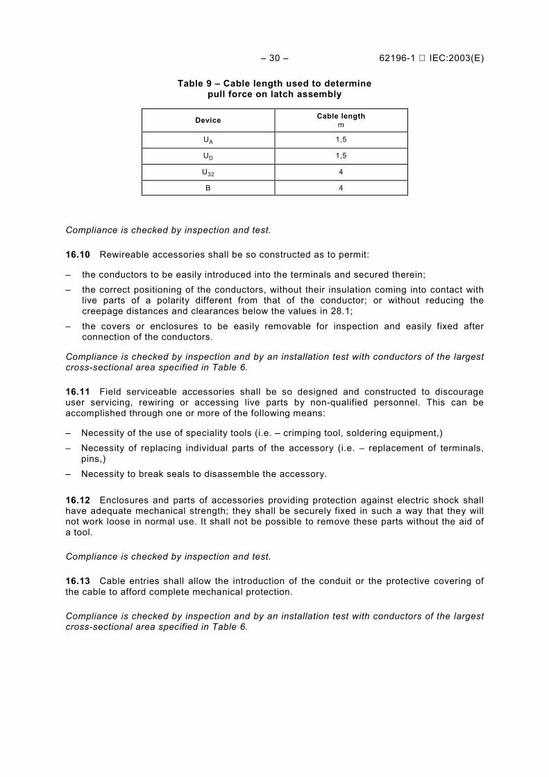
– 30 – 62196-1 IEC:2003(E)
Table 9 – Cable length used to determinepull force on latch assembly
Device Cable lengthm
UA 1,5
UD 1,5
U32 4
B 4
Compliance is checked by inspection and test.
16.10 Rewireable accessories shall be so constructed as to permit:
– the conductors to be easily introduced into the terminals and secured therein;– the correct positioning of the conductors, without their insulation coming into contact with
live parts of a polarity different from that of the conductor; or without reducing thecreepage distances and clearances below the values in 28.1;
– the covers or enclosures to be easily removable for inspection and easily fixed afterconnection of the conductors.
Compliance is checked by inspection and by an installation test with conductors of the largestcross-sectional area specified in Table 6.
16.11 Field serviceable accessories shall be so designed and constructed to discourageuser servicing, rewiring or accessing live parts by non-qualified personnel. This can beaccomplished through one or more of the following means:
– Necessity of the use of speciality tools (i.e. – crimping tool, soldering equipment,)– Necessity of replacing individual parts of the accessory (i.e. – replacement of terminals,
pins,)– Necessity to break seals to disassemble the accessory.
16.12 Enclosures and parts of accessories providing protection against electric shock shallhave adequate mechanical strength; they shall be securely fixed in such a way that they willnot work loose in normal use. It shall not be possible to remove these parts without the aid ofa tool.
Compliance is checked by inspection and test.
16.13 Cable entries shall allow the introduction of the conduit or the protective covering ofthe cable to afford complete mechanical protection.
Compliance is checked by inspection and by an installation test with conductors of the largestcross-sectional area specified in Table 6.
62196-1 IEC:2003(E) – 31 –
16.14 Insulating linings, barriers and the like shall have adequate mechanical strength. Theyshall be secured to the enclosure or body in such a way that they cannot be removed withoutbeing seriously damaged, or be so designed that they cannot be replaced in an incorrectposition.
Compliance is checked by inspection and by the tests of 20.2 and 26.3
NOTE The use of adhesives is allowed for fixing insulating linings.
16.15 The force to insert and withdraw a plug or a vehicle connector shall be less than 80 N.The movement of either of these accessories need not necessarily be a single linearmovement. The insertion and withdrawal force shall be applied as required by each stage ofthe insertion and withdrawal movement. The manufacturer shall state the position anddirection at which this force(s) shall be applied.
Compliance may be checked by a spring scale or the following test.
The fixed accessory (the socket-outlet or vehicle inlet) shall be mounted such that the matingaccessory moves vertically downward into it during the first stage of insertion. A principalweight of 7,2 kg is suitable suspended from the matching accessory. A supplementary weightof 0,8 kg is allowed to fall from a height of 5 cm onto the principal weight. The movingaccessory shall enter the fixed accessory to the position required to engage the contactsproperly.
The operation is then repeated for any subsequent movements.
The test is repeated using a fixed weight of 2,0 kg and no supplementary weight. The movingaccessory shall not become inserted in the fixed accessory to the extent specified by themanufacturer. These tests are carried out in reverse also to check the withdrawal force todetermine that the contacts disengage properly.
17 Construction of socket-outlets
When a plug is not engaged, socket-outlets shall be totally enclosed when fitted with screwedconduits, or sheathed cables. Polyvinyl chloride sheathed cables are not excluded. Themeans for achieving total enclosure and that for ensuring the marked degree of protection, ifany, shall be securely fixed to the socket-outlet. In addition, when a plug is completelyengaged, the socket-outlet shall incorporate means for ensuring the marked degree ofprotection.
Lid springs, if any, shall be of corrosion-resistant material, such as bronze, stainless steel, orother suitable material adequately protected against corrosion.
IP44 socket-outlets, designed for only one mounting position, may have provision for openinga drain-hole at least 5 mm in diameter or 20 mm2 in area with a width of at least 3 mm whichis effective when the socket-outlet is in the mounting position.
NOTE 1 The total enclosure and the marked degree of protection may be achieved by means of a lid.
NOTE 2 A drain-hole in the back of the enclosure of a socket-outlet, up to IP44 intended to be mounted on avertical wall, is deemed to be effective only if the design of the enclosure ensures a clearance of at least 5 mmfrom the wall, or provides a drainage channel of at least the size specified.
Compliance is checked by inspection, by measurement and by the tests of Clauses 20,21 and 23.
– 32 – 62196-1 IEC:2003(E)
18 Construction of plugs and vehicle connectors
18.1 The enclosure of plugs and vehicle connectors shall completely enclose the terminalsand the ends of the flexible cable.
The construction of rewireable plugs and vehicle connectors shall be such that the conductorscan be properly connected and the cores kept in place so that there is no risk of contactbetween them from the point of separation of the cores to the terminals.
Accessories shall be so designed that they can only be reassembled so as to ensure thecorrect relationship between the components as originally assembled.
Compliance is checked by inspection and, if necessary, by manual test.
18.2 The various parts of a plug or vehicle connector shall be reliably fixed to one another insuch a way that they will not work loose in normal use. It shall not be possible to dismantleplugs or vehicle connectors without the aid of a tool.
Compliance is checked by manual test and by the test of 25.3.
18.3 Plugs shall incorporate means for ensuring the marked degree of protection when incomplete engagement with the complementary accessory.
Where there is an attached cap, which cannot be removed without the aid of a tool, then theplug shall also meet this requirement when that cap is correctly fitted.
It shall not be possible to dismantle these means without the aid of a tool.
Compliance is checked by inspection and by the tests of Clauses 20 and 21.
18.4 Vehicle connectors shall be totally enclosed when fitted with a flexible cable as innormal use and when not in engagement with the vehicle inlet. In addition, they shallincorporate means for ensuring the marked degree of protection when in completeengagement with the vehicle inlet.
NOTE The marked degree of protection when not in engagement with the vehicle inlet may be achieved by meansof a lid or cover.
The means for ensuring the marked degree of protection shall be securely fixed to the vehicleconnector.
Lid springs shall be of corrosion-resistant material, such as bronze, stainless steel or othersuitable materials adequately protected against corrosion.
Compliance is checked by inspection and by the tests of Clauses 20, 21 and 23.
19 Construction of vehicle inlets
19.1 Vehicle inlets shall incorporate means for ensuring the marked degree of protectionwhen an appropriate vehicle connector is completely engaged.
The IP degree of protection of the vehicle inlet must be considered, assuming that anyaccessible parts that may be live when a vehicle connector is connected are not live when thevehicle connector is removed and may be touched by the test finger.
62196-1 IEC:2003(E) – 33 –
Where there is an attached cap, which cannot be removed without the aid of a tool, then thevehicle inlets shall also meet this requirement when that cap is correctly fitted.
It shall not be possible to dismantle these means without the aid of a tool.
Compliance is checked by inspection and by the tests of Clauses 19 and 20. If the degree ofprotection when no connector is present, the vehicle manufacturer must ensure the IP degree.
19.2 Vehicle inlets having rated operating voltage exceeding 50 V shall be provided withearthing contacts.
Compliance is checked by inspection.
19.3 IP44 vehicle inlets, designed for only one mounting position, may have provision foropening a drain-hole at least 5 mm in diameter or 20 mm2 in area with a width of at least3 mm which is effective when the socket-outlet is in the mounting position.
20 Degrees of protection
20.1 Accessories shall have the minimum degrees of protection of IP44. The vehicle inlet, inroad position and in combination with the protection provided by the vehicle manufacturer,shall have the minimum degrees of protection of IP55.
NOTE “In road position” means that the vehicle is stationary and ready to be driven.
Compliance is checked by the appropriate tests mentioned in the subclauses below.
The tests are made on accessories fitted with the cables or conduits for which they aredesigned, screwed glands and fixing screws of enclosures and covers being tightened witha torque equal to two-thirds of that applied in the tests of 26.5 or 27.1, as appropriate.
Screwed caps or lids, if any, are tightened as in normal use.
Socket-outlets are mounted on a vertical surface so that the open drain-hole, if any, is in thelowest position and remains open.
Vehicle inlets are mounted in position as intended in the vehicle. Tests shall be conductedwith any doors, access panels, covers, etc. provided by the vehicle both in the unmated,open, and closed (in the road position) positions. Vehicle connectors are placed in the mostunfavourable position and the drain-hole, if any, remains open.
Socket-outlets and vehicle connectors are tested with and without the complementaryaccessory in engagement, the means for ensuring the required degree of protection againstmoisture being positioned as in normal use.
Plugs and vehicle inlets are tested as described in 18.3 or 19.1.
20.2 Accessories shall be tested in accordance with 20.1 and IEC 60529. When the firstcharacteristic numeral is 5, category 2 shall apply.
Immediately after the tests the samples, while still mounted in the test position, shallwithstand the dielectric strength test specified in 21.3, and inspection shall show that waterhas not entered the samples to any appreciable extent and has not reached live parts.
– 34 – 62196-1 IEC:2003(E)
20.3 All accessories shall be proof against humid conditions which may occur in normal use.
Compliance is checked by the humidity treatment described in this subclause, followedimmediately by the measurement of the insulation resistance and by the dielectric strengthtest, specified in Clause 21. Cable entries, if any, are left open; if knockouts are provided, oneof them is opened.
Covers, which can be removed without the aid of a tool, are removed and subjected to thehumidity treatment with the main part; spring lids are open during this treatment.
The humidity treatment is carried out in a humidity cabinet containing air with a relativehumidity maintained between 91 % and 95 %. The temperature of the air, at all places wheresamples can be located, is maintained within 1 °C of any convenient value T between 20 °Cand 30 °C.
Before being placed in the humidity cabinet, the samples are brought to a temperaturebetween T and T + 4 °C.
The samples are kept in the cabinet for 7 days (168 h).
NOTE In most cases, the samples may be brought to the temperature specified by keeping them at thistemperature for at least 4 h before the humidity treatment.
A relative humidity between 91 % and 95 % can be obtained by placing in the humidity cabinet a saturated solutionof sodium sulphate (Na2SO4) or potassium nitrate (KNO3) in water, having a sufficiently large contact surface withthe air.
In order to achieve the specified conditions within the cabinet, it is necessary to ensure constant circulation of theair within it and, in general, to use a cabinet that is thermally insulated.
After this treatment, the samples shall show no damage within the meaning of this standard.
21 Insulation resistance and dielectric strength
21.1 The insulation resistance and the dielectric strength of accessories shall be adequate.
Compliance is checked by the tests of 21.2 and 21.3, which are made immediately after thetest of 20.3 in the humidity cabinet or in the room in which the samples were broughtto the prescribed temperature, after reassembly of covers that may have been removed.
Accessories with enclosures of thermoplastic material are subjected to the additional testof 21.4.
NOTE For the purpose of these tests, the neutral contact, the pilot contact, the communications contacts, and anyother contacts for signal or control purposes (positions 9 – 14 for “universal” accessories, positions 9 – 12 for“basic” accessories) if any, are each considered as a pole.
21.2 The insulation resistance is measured with a d.c. voltage of approximately 500 Vapplied, the measurement being made 1 min after application of the voltage.
The insulation resistance shall be not less than 5 MΣ.
21.2.1 For socket-outlets and vehicle connectors, the insulation resistance is measuredconsecutively:
a) between all poles connected together and the body, the measurement being made withand also without a plug or vehicle inlet engaged;
b) between each pole in turn and all others, these being connected to the body, with a plugor vehicle inlet engaged;
62196-1 IEC:2003(E) – 35 –
c) between any metal enclosure and metal foil in contact with the inner surface of itsinsulating lining, if any, a gap of approximately 4 mm being left between the metal foil andthe edge of the lining.
NOTE The term “body” includes all accessible metal parts, metal foil in contact with the outer surface of externalparts of insulating material, other than the engagement face of vehicle connectors and plugs, fixing screws ofbases, enclosures and covers, external assembly screws and earthing terminals, if any.
21.2.2 For plugs and vehicle inlets, the insulation resistance is measured consecutively:
a) between all poles connected together and the body;b) between each pole in turn and all others, these being connected to the body;c) between any metal enclosure and metal foil in contact with the inner surface of its
insulating lining, if any, a gap of approximately 4 mm being left between the metal foil andthe edge of the lining.
21.3 A test voltage of substantially sine-wave form, having a frequency of 50 Hz/60 Hz andthe value shown in Table 10, is applied for 1 min between the parts indicated in 21.2.1 and21.2.2.
NOTE For the parts indicated in 21.2.1(a) and 21.2.2(a), which are used in non-power circuits [control pilot circuit,communications circuits, including clean data earth, or other signal or control circuits (positions 9 – 14 for«universal» accessories, positions 9 – 12 for “basic” accessories)], each circuit may be tested separately, using atest voltage based on the highest voltage in the circuit. For the parts indicated in 20.2.1(b) and 20.2.2(b), which areused in non-power circuits [control pilot circuit, communications circuits, including clean data earth, or other signalor control circuits (positions 9 – 14 for “universal” accessories, positions 9 – 12 for “basic” accessories)], the testvoltage between these circuits and the power circuits shall be based on the voltage of the power circuit.
Table 10 – Test voltage for dielectric strength test
Insulation voltage of the accessory a Test voltageV
Up to and including 50
over 50 up to and including 415
over 415 up to and including 500
over 500
500
2 000 b
2 500
3 000
a The insulation voltage is at least equal to the highest rated operating voltage.b This value is increased to 2 500 V for metal enclosures lined with insulating material.
Initially, no more than half the prescribed voltage is applied, and then it is raised rapidlyto the full value.
No flashover or breakdown shall occur during the test.
NOTE Glow discharges without drop in voltage are neglected.
21.4 Immediately after the test of 21.3, it shall be verified that for accessories withenclosures of thermoplastic material, the means of providing non-interchangeability have notbeen impaired.
– 36 – 62196-1 IEC:2003(E)
22 Breaking capacity
22.1 Accessories intended for current interruption (making and breaking under load) shallhave adequate breaking capacity.
NOTE Accessories rated 250 A a.c. or 400 A d.c. are rated for disconnecting use only, not for current interruption,and are intended to be used with a control pilot circuit system and interlock provided as a part of the equipment orpart of the EV. These accessories are not identified as being for current interruption.
Compliance is checked by testing mating complementary accessories in accordancewith 22.2.
22.2 The test position shall be horizontal or, if not possible, as in normal use.
The plug or vehicle connector is inserted into and withdrawn from the socket-outlet or vehicleinlet at a rate of 7,5 strokes per minute, or at the rate recommended by the manufacturer,whichever is less. The speed of insertion and separation of the plug or vehicle connector shallbe (0,8 ± 0,1) m/s.
The measurement of speed is made by recording the interval of time between insertion orseparation of the main contacts and the insertion or separation of the earthing contact,relative to the distance.
Electrical contacts shall be maintained for no more than 4 s and no less than 2 s.
The movement(s) of a plug or vehicle connector during insertion into the mating accessorymay be more complex than a single linear movement. At the manufacturer’s option, thetest may be made with the insertion and withdrawal made manually or by machine.The movement may be limited to provide adequate separation of the mating contacts.
The number of cycles is specified in Table 11. A stroke is an insertion or a withdrawal of aplug or vehicle connector with its mating accessory. A cycle is composed of two strokes, onefor insertion and one for withdrawal.
Accessories are tested as defined in Table 11.
For accessories rated for both a.c. and d.c. operation, a new set of accessories shall betested on each circuit.
The test is made using the connections shown in Figure 3 except that for accessories havinga rated voltage of 380 V – 415 V, the metal support is permanently connected to the neutral.In all other cases, for two-pole accessories, the selector switch C connecting the metalsupport and the accessible metal parts to one of the poles of the supply, is operated after halfthe number of strokes. For three-pole accessories, the selector switch C is operated afterone-third of the number of strokes and again after two-thirds of the number of strokes, so asto connect each pole in turn.
Resistors and inductors are not connected in parallel, except that, if an air-core inductor isused, a resistor taking approximately 1 % of the current through the inductor is connected inparallel with it. Iron-core inductors may be used, provided the current has substantially sine-wave form. For the tests on three-pole accessories, three-core inductors are used.
After the test, the samples shall show no damage impairing their further use.
62196-1 IEC:2003(E) – 37 –
Table 11 – Breaking capacity
Ratedcurrent
A
Testcurrent
A
Testvoltage
cos ϕ ϕ ϕ ϕ ± 0,05 Number of cycleson load
30 – 32
250
400 (d.c.)
40
250
b
1,1 × maximum rated
1,1 × maximum rated
0,55 × maximum rated
0,8
0,8
–
50
– a
– a
a A device rated as “not being for current interruption” tested in accordance with 22.3.b Under consideration.
22.3 An accessory rated 250 A a.c. or 400 A d.c. shall have sufficient breaking capacity tointerrupt the circuit in case of a fault, without any indication of a fire or shock hazard. Theaccessory need not remain functional after the completion of the test. It shall not be used forany further tests.
Compliance is checked by testing the mating accessories in accordance with 22.2. for up tothree making and breaking operations under the indicated load.
Following the test, the accessories shall comply with a dielectric test in accordance with 21.3,with voltage applied between the parts as indicated in 21.2.1 b) or 21.2.2 b), as applicable.
23 Normal operation
23.1 Accessories shall withstand, without excessive wear or other harmful effect, themechanical, electrical and thermal stresses occurring in normal use.
Compliance is checked by testing any accessory with a new complementary accessory.
This test is carried out by the same means as in Clause 22 used in the manner indicated andin the test position as specified in Clause 22.
The test is made using the connections indicated in Clause 22, the selector switch C beingoperated as prescribed in that clause.
The samples are tested at maximum rated operating voltage and rated current.
Accessories are tested for the number of cycles of operation specified and as defined inTable 12, where a cycle is composed of two strokes, one for insertion and one for withdrawal.
Accessories are tested with a.c. in a circuit with cos ϕ as specified in Table 12.
23.2 For accessories rated for both a.c. and d.c. operation, a separate set of accessoriesshall be tested on each circuit.

– 38 – 62196-1 IEC:2003(E)
23.3 During the test, no sustained arcing shall occur.
After the test, the samples shall show:
– no wear impairing the further use of the accessory or of its interlock, if any;– no deterioration of enclosures or barriers;– no damage to the entry holes for the plug contacts that might impair proper working;– no loosening of electrical or mechanical connections;– no seepage of sealing compound;– the continuity between mating signal and pilot contacts are maintained.
The samples shall then withstand a dielectric strength test made in accordance with 21.3, thetest voltage, however, being decreased by 500 V.
NOTE The humidity treatment is not repeated before the dielectric strength test of this subclause.
Table 12 – Normal operation
Cycles of operationRated currentA
cos ϕϕϕϕ ± 0,05load no-load
2
30 – 32
250
400 (d.c.)
0,8
0,6
0,8
–
6 000
5 000 a
5 000 a
–
4 000
5 000
5 000
10 000
a For an accessory provided with an interlock (e.g. – pilot circuit) or rated as “not intendedfor current interruption”, the number of cycles of operation under load is 50 and no-loadis 10,000.
23.4 Lid springs or other devices which are not automatically operated during the normaloperation test, if any, are tested separately by completely opening and closing the part, thenumber of times the part is opened being the same as the maximum number of insertions ofthe plug specified in Table 12.
24 Temperature rise
24.1 Accessories shall be so constructed that the temperature rise in normal use is notexcessive.
Compliance is checked by testing any accessory with a new complementary accessory.
Accessories are to be mounted as intended in normal use.
The test current is an alternating current of the value shown in Table 13.
Unless a dedicated cable is provided as specified by the manufacturer, rewireableaccessories are fitted with conductors of a cross-sectional area as specified in Table 13,the terminal screws or nuts being tightened with a torque specified on the product or in theinstruction sheets by the manufacturer or equal to two-thirds of that specified in Table 18.
For the purpose of this test, a length of at least 2 m of the cable shall be connected to theterminals.
Non-rewireable accessories are tested as delivered.
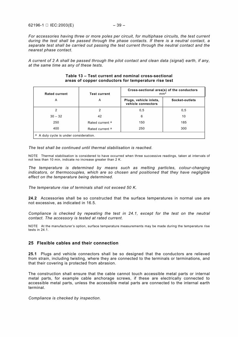
62196-1 IEC:2003(E) – 39 –
For accessories having three or more poles per circuit, for multiphase circuits, the test currentduring the test shall be passed through the phase contacts. If there is a neutral contact, aseparate test shall be carried out passing the test current through the neutral contact and thenearest phase contact.
A current of 2 A shall be passed through the pilot contact and clean data (signal) earth, if any,at the same time as any of these tests.
Table 13 – Test current and nominal cross-sectionalareas of copper conductors for temperature rise test
Cross-sectional area(s) of the conductorsmm²Rated current
A
Test current
A Plugs, vehicle inlets,vehicle connectors
Socket-outlets
2
30 – 32
250
400
2
42
Rated current a
Rated current a
0,5
6
150
250
0,5
10
185
300
a A duty cycle is under consideration.
The test shall be continued until thermal stabilisation is reached.
NOTE Thermal stabilisation is considered to have occurred when three successive readings, taken at intervals ofnot less than 10 min, indicate no increase greater than 2 K.
The temperature is determined by means such as melting particles, colour-changingindicators, or thermocouples, which are so chosen and positioned that they have negligibleeffect on the temperature being determined.
The temperature rise of terminals shall not exceed 50 K.
24.2 Accessories shall be so constructed that the surface temperatures in normal use arenot excessive, as indicated in 16.5.
Compliance is checked by repeating the test in 24.1, except for the test on the neutralcontact. The accessory is tested at rated current.
NOTE At the manufacturer’s option, surface temperature measurements may be made during the temperature risetests in 24.1.
25 Flexible cables and their connection
25.1 Plugs and vehicle connectors shall be so designed that the conductors are relievedfrom strain, including twisting, where they are connected to the terminals or terminations, andthat their covering is protected from abrasion.
The construction shall ensure that the cable cannot touch accessible metal parts or internalmetal parts, for example cable anchorage screws, if these are electrically connected toaccessible metal parts, unless the accessible metal parts are connected to the internal earthterminal.
Compliance is checked by inspection.

– 40 – 62196-1 IEC:2003(E)
25.2 Requirements for plugs and vehicle connectors
25.2.1 Non-rewireable plugs and vehicle connectors Accessories shall be provided with asuitable flexible cable appropriate for the rating of the accessory and as specified by themanufacturer.
Non-rewireable plugs and vehicle connectors shall be tested as a cable assembly.
Compliance is checked by inspection and by the test of 25.3.
25.2.2 Rewireable plugs and vehicle connectors
Rewireable accessories shall be provided with a strain relief means designed to preventthe twisting of the cable that may occur. If any one of the components is not in position in theaccessory as provided, an instruction sheet shall be provided to identify the necessary parts,the method of assembly and the maximum and minimum size cable for which it is suitable.
The design of the cable anchorage shall be such that the anchorage or components areproperly positioned relative to the accessory when assembled.
Cable anchorages shall present no sharp edges to the cable and shall be so designed that theanchorages or their components are not likely to be lost when the enclosure of the accessoryand not the cable anchorage is being opened.
Makeshift methods, such as tying the cable into a knot or tying the ends with string, shall notbe used.
Cable anchorages and cable inlets shall be suitable for the different types of flexible cablethat may be connected.
If a cable entrance is provided with a sleeve to prevent damage to the cable, this sleeve shallbe of insulating material and shall be smooth and free from burrs.
If a bell-mouthed opening is provided, the diameter at the end shall be at least 1,5 times thediameter of the cable with the largest cross-sectional area to be connected.
Helical metal springs, whether bare or covered with insulating material, are not allowed ascable sleeves.
Compliance is checked by inspection and by the test of 25.3.
25.3 Plugs and vehicle connectors provided with a flexible cable are subjected to a pull testin apparatus similar to that shown in Figure 4, followed by a torque test.
Non-rewireable accessories are tested as delivered.
Rewireable accessories are tested with the maximum and minimum size cables recommendedby the manufacturer.
Conductors of the cable of rewireable accessories are introduced into the terminals, theterminal screws being tightened just sufficiently to prevent the conductors from easilychanging their position.
The cable anchorage is used in the normal way, clamping screws being tightened with atorque equal to two-thirds of that specified in 27.1. After reassembly of the sample, with cable
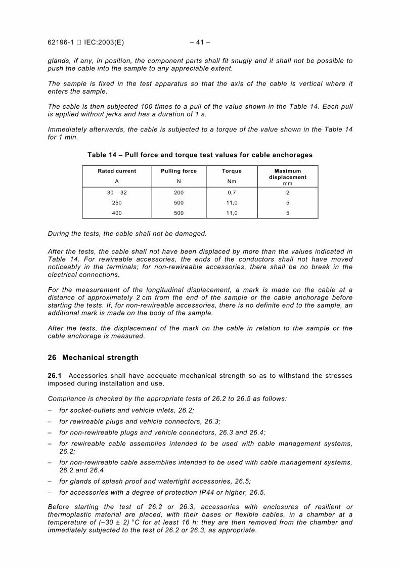
62196-1 IEC:2003(E) – 41 –
glands, if any, in position, the component parts shall fit snugly and it shall not be possible topush the cable into the sample to any appreciable extent.
The sample is fixed in the test apparatus so that the axis of the cable is vertical where itenters the sample.
The cable is then subjected 100 times to a pull of the value shown in the Table 14. Each pullis applied without jerks and has a duration of 1 s.
Immediately afterwards, the cable is subjected to a torque of the value shown in the Table 14for 1 min.
Table 14 – Pull force and torque test values for cable anchorages
Rated current
A
Pulling force
N
Torque
Nm
Maximumdisplacement
mm30 – 32
250
400
200
500
500
0,7
11,0
11,0
2
5
5
During the tests, the cable shall not be damaged.
After the tests, the cable shall not have been displaced by more than the values indicated inTable 14. For rewireable accessories, the ends of the conductors shall not have movednoticeably in the terminals; for non-rewireable accessories, there shall be no break in theelectrical connections.
For the measurement of the longitudinal displacement, a mark is made on the cable at adistance of approximately 2 cm from the end of the sample or the cable anchorage beforestarting the tests. If, for non-rewireable accessories, there is no definite end to the sample, anadditional mark is made on the body of the sample.
After the tests, the displacement of the mark on the cable in relation to the sample or thecable anchorage is measured.
26 Mechanical strength
26.1 Accessories shall have adequate mechanical strength so as to withstand the stressesimposed during installation and use.
Compliance is checked by the appropriate tests of 26.2 to 26.5 as follows:
– for socket-outlets and vehicle inlets, 26.2;– for rewireable plugs and vehicle connectors, 26.3;– for non-rewireable plugs and vehicle connectors, 26.3 and 26.4;– for rewireable cable assemblies intended to be used with cable management systems,
26.2;– for non-rewireable cable assemblies intended to be used with cable management systems,
26.2 and 26.4– for glands of splash proof and watertight accessories, 26.5;– for accessories with a degree of protection IP44 or higher, 26.5.
Before starting the test of 26.2 or 26.3, accessories with enclosures of resilient orthermoplastic material are placed, with their bases or flexible cables, in a chamber at atemperature of (–30 ± 2) °C for at least 16 h; they are then removed from the chamber andimmediately subjected to the test of 26.2 or 26.3, as appropriate.
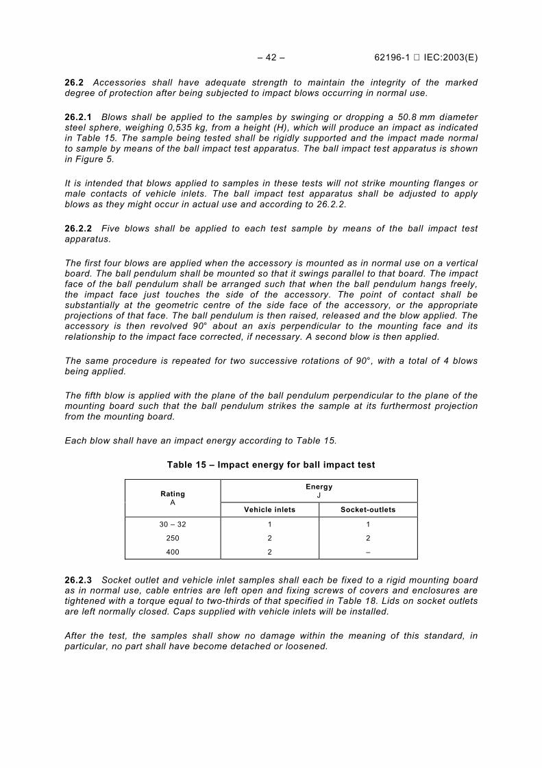
– 42 – 62196-1 IEC:2003(E)
26.2 Accessories shall have adequate strength to maintain the integrity of the markeddegree of protection after being subjected to impact blows occurring in normal use.
26.2.1 Blows shall be applied to the samples by swinging or dropping a 50.8 mm diametersteel sphere, weighing 0,535 kg, from a height (H), which will produce an impact as indicatedin Table 15. The sample being tested shall be rigidly supported and the impact made normalto sample by means of the ball impact test apparatus. The ball impact test apparatus is shownin Figure 5.
It is intended that blows applied to samples in these tests will not strike mounting flanges ormale contacts of vehicle inlets. The ball impact test apparatus shall be adjusted to applyblows as they might occur in actual use and according to 26.2.2.
26.2.2 Five blows shall be applied to each test sample by means of the ball impact testapparatus.
The first four blows are applied when the accessory is mounted as in normal use on a verticalboard. The ball pendulum shall be mounted so that it swings parallel to that board. The impactface of the ball pendulum shall be arranged such that when the ball pendulum hangs freely,the impact face just touches the side of the accessory. The point of contact shall besubstantially at the geometric centre of the side face of the accessory, or the appropriateprojections of that face. The ball pendulum is then raised, released and the blow applied. Theaccessory is then revolved 90° about an axis perpendicular to the mounting face and itsrelationship to the impact face corrected, if necessary. A second blow is then applied.
The same procedure is repeated for two successive rotations of 90°, with a total of 4 blowsbeing applied.
The fifth blow is applied with the plane of the ball pendulum perpendicular to the plane of themounting board such that the ball pendulum strikes the sample at its furthermost projectionfrom the mounting board.
Each blow shall have an impact energy according to Table 15.
Table 15 – Impact energy for ball impact test
EnergyJRating
AVehicle inlets Socket-outlets
30 – 32
250
400
1
2
2
1
2
–
26.2.3 Socket outlet and vehicle inlet samples shall each be fixed to a rigid mounting boardas in normal use, cable entries are left open and fixing screws of covers and enclosures aretightened with a torque equal to two-thirds of that specified in Table 18. Lids on socket outletsare left normally closed. Caps supplied with vehicle inlets will be installed.
After the test, the samples shall show no damage within the meaning of this standard, inparticular, no part shall have become detached or loosened.

62196-1 IEC:2003(E) – 43 –
Accessories with a degree of protection IP44 and higher shall withstand the relevant testspecified in Clause 20.
Accessories with enclosures of thermoplastic material shall withstand the test of 21.4.
NOTE Small chips, cracks and dents, which do not adversely affect the protection against electrical shock ormoisture, are neglected. In case of doubts, appropriate tests of Clauses 19 and 20 are carried out.
26.3 Rewireable plugs and vehicle connectors are fitted with a small section (approximately200 mm) of the lightest type of flexible cable of the smallest cross-sectional arearecommended by the manufacturer.
Non-rewireable plugs and vehicle connectors are tested with a small section (approximately200 mm) of the flexible cable as delivered.
Cable assemblies specified to be used with cable management systems are to be testedper 26.2
The free end of the cable and an additional rope or other flexible means, etc, attached to theflexible cable, both having a total length of 2,25 m, is fixed to a wall at a height of 1 m abovethe floor, as shown in Figure 6.
The sample is held so that the cable is horizontal and then it is allowed to fall on to a concretefloor. This is done eight times, the cable being rotated through 45° at its fixing each time.
After the test, the samples shall show no damage within the meaning of this standard; inparticular, no part shall have become detached or loosened.
Accessories with a degree of protection IP44 and higher shall withstand the relevant testspecified in Clause 20.
Accessories with enclosures of thermoplastic material shall withstand the test of 21.4.
NOTE Small chips and dents, which do not adversely affect the protection against electric shock or moisture, areneglected.
26.4 Non-rewireable accessories are subjected to a flexing test in an apparatus similar tothat shown in Figure 7.
The sample is fixed to the oscillating member of the apparatus so that, when this is at themiddle of its travel, the axis of the flexible cable, where it enters the sample, is vertical andpasses through the axis of oscillation.
The oscillating member is so positioned that the flexible cable makes the minimum lateralmovement when the oscillating member of the test apparatus is moved over its full travel.
The cable is loaded with a weight such that the force applied is as shown in the followingTable 16.
Table 16 – Mechanical load flexing test
Rated currentA
ForceN
30 – 32
250
400
25
75
100
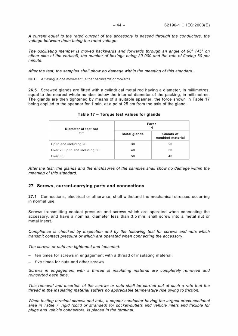
– 44 – 62196-1 IEC:2003(E)
A current equal to the rated current of the accessory is passed through the conductors, thevoltage between them being the rated voltage.
The oscillating member is moved backwards and forwards through an angle of 90° (45° oneither side of the vertical), the number of flexings being 20 000 and the rate of flexing 60 perminute.
After the test, the samples shall show no damage within the meaning of this standard.
NOTE A flexing is one movement, either backwards or forwards.
26.5 Screwed glands are fitted with a cylindrical metal rod having a diameter, in millimetres,equal to the nearest whole number below the internal diameter of the packing, in millimetres.The glands are then tightened by means of a suitable spanner, the force shown in Table 17being applied to the spanner for 1 min, at a point 25 cm from the axis of the gland.
Table 17 – Torque test values for glands
ForceNDiameter of test rod
mm Metal glands Glands ofmoulded material
Up to and including 20
Over 20 up to and including 30
Over 30
30
40
50
20
30
40
After the test, the glands and the enclosures of the samples shall show no damage within themeaning of this standard.
27 Screws, current-carrying parts and connections
27.1 Connections, electrical or otherwise, shall withstand the mechanical stresses occurringin normal use.
Screws transmitting contact pressure and screws which are operated when connecting theaccessory, and have a nominal diameter less than 3,5 mm, shall screw into a metal nut ormetal insert.
Compliance is checked by inspection and by the following test for screws and nuts whichtransmit contact pressure or which are operated when connecting the accessory.
The screws or nuts are tightened and loosened:
– ten times for screws in engagement with a thread of insulating material;– five times for nuts and other screws.
Screws in engagement with a thread of insulating material are completely removed andreinserted each time.
This removal and insertion of the screws or nuts shall be carried out at such a rate that thethread in the insulating material suffers no appreciable temperature rise owing to friction.
When testing terminal screws and nuts, a copper conductor having the largest cross-sectionalarea in Table 7, rigid (solid or stranded) for socket-outlets and vehicle inlets and flexible forplugs and vehicle connectors, is placed in the terminal.
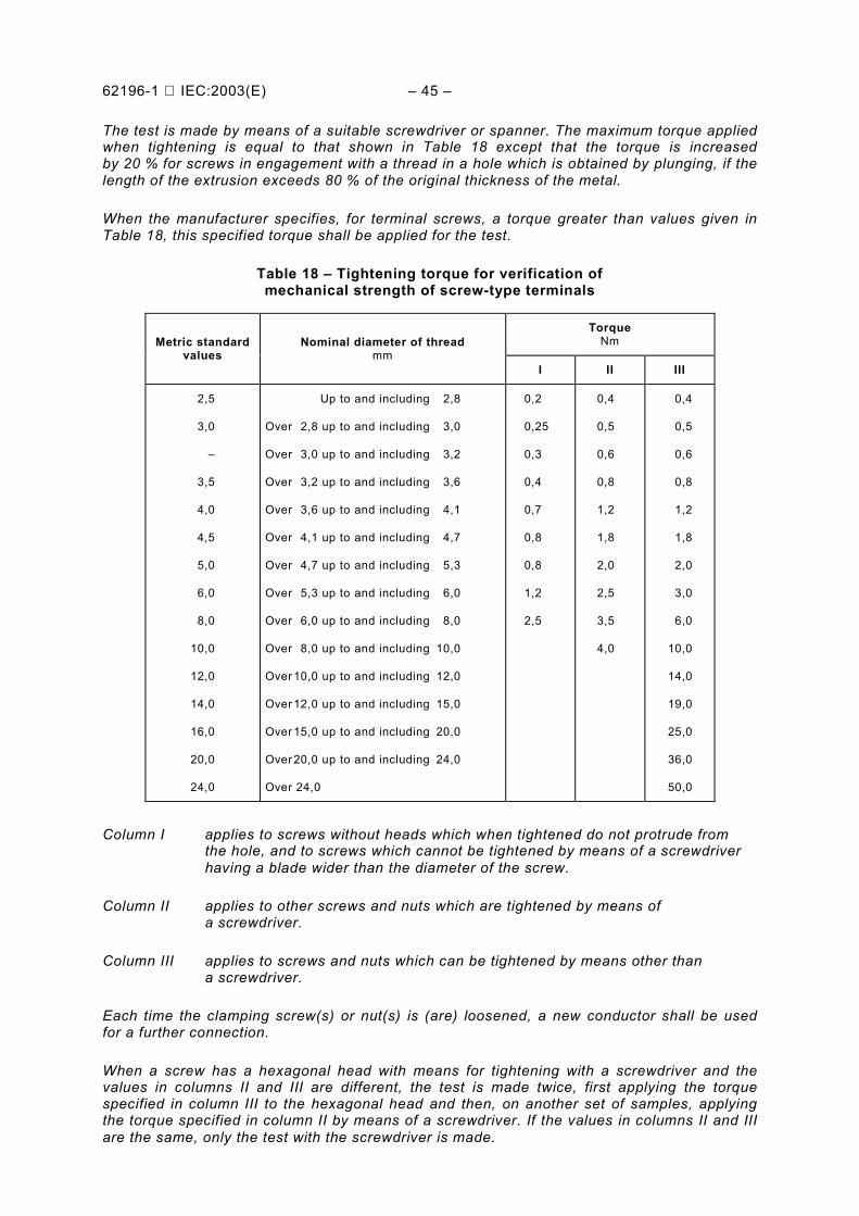
62196-1 IEC:2003(E) – 45 –
The test is made by means of a suitable screwdriver or spanner. The maximum torque appliedwhen tightening is equal to that shown in Table 18 except that the torque is increasedby 20 % for screws in engagement with a thread in a hole which is obtained by plunging, if thelength of the extrusion exceeds 80 % of the original thickness of the metal.
When the manufacturer specifies, for terminal screws, a torque greater than values given inTable 18, this specified torque shall be applied for the test.
Table 18 – Tightening torque for verification ofmechanical strength of screw-type terminals
TorqueNmMetric standard
valuesNominal diameter of thread
mmI II III
2,5
3,0
–
3,5
4,0
4,5
5,0
6,0
8,0
10,0
12,0
14,0
16,0
20,0
24,0
Up to and including 2,8
Over 2,8 up to and including 3,0
Over 3,0 up to and including 3,2
Over 3,2 up to and including 3,6
Over 3,6 up to and including 4,1
Over 4,1 up to and including 4,7
Over 4,7 up to and including 5,3
Over 5,3 up to and including 6,0
Over 6,0 up to and including 8,0
Over 8,0 up to and including 10,0
Over 10,0 up to and including 12,0
Over 12,0 up to and including 15,0
Over 15,0 up to and including 20,0
Over 20,0 up to and including 24,0
Over 24,0
0,2
0,25
0,3
0,4
0,7
0,8
0,8
1,2
2,5
0,4
0,5
0,6
0,8
1,2
1,8
2,0
2,5
3,5
4,0
0,4
0,5
0,6
0,8
1,2
1,8
2,0
3,0
6,0
10,0
14,0
19,0
25,0
36,0
50,0
Column I applies to screws without heads which when tightened do not protrude fromthe hole, and to screws which cannot be tightened by means of a screwdriverhaving a blade wider than the diameter of the screw.
Column II applies to other screws and nuts which are tightened by means ofa screwdriver.
Column III applies to screws and nuts which can be tightened by means other thana screwdriver.
Each time the clamping screw(s) or nut(s) is (are) loosened, a new conductor shall be usedfor a further connection.
When a screw has a hexagonal head with means for tightening with a screwdriver and thevalues in columns II and III are different, the test is made twice, first applying the torquespecified in column III to the hexagonal head and then, on another set of samples, applyingthe torque specified in column II by means of a screwdriver. If the values in columns II and IIIare the same, only the test with the screwdriver is made.

– 46 – 62196-1 IEC:2003(E)
After the test for clamping screws or nuts, the clamping unit shall not have undergonechanges that adversely affect its further use.
NOTE For mantle terminals, the specified nominal diameter is that of the slotted stud.
For mantle terminals in which the nut is tightened by means other than a screwdriver and for which the nominalscrew diameter is over 10 mm, the value of the torque is under consideration.
Screws or nuts which are operated when connecting up the accessory include terminal screws or nuts, assemblyscrews, screws for fixing covers, etc. but not connections for screwed conduits and screws for fixing socket-outletsor vehicle inlets to the mounting surface.
The shape of the blade of the test screwdriver shall suit the head of the screw to be tested.
The screws and nuts shall not be tightened in jerks.
NOTE Damage to covers is neglected. Connections made by screws will have been partially checked by the testof Clauses 23 and 26.
27.2 Screws in engagement with a thread of insulating material and which are operatedwhen connecting up the accessory shall have a length of engagement of at least 3 mm plusone-third of the nominal screw diameter, or 8 mm, whichever is the shorter.
Correct introduction of the screw into the threaded hole shall be ensured.
Compliance is checked by inspection, by measurement and by manual test.
NOTE The requirement with regard to correct introduction is met if introduction of the screw in a slanting manneris prevented, for example by guiding the screw by the pan to be fixed, by a recess in the threaded hole or by theuse of a screw with the leading thread removed.
27.3 Electrical connections shall be so designed that the contact pressure is not transmittedthrough insulating material other than ceramic, pure mica or other material withcharacteristics no less suitable, unless there is sufficient resiliency in the metallic parts tocompensate for any shrinkage or yielding of the insulating material.
Compliance is checked by inspection.
NOTE The suitability of the material is considered with respect to its dimensional stability.
27.4 Screws and rivets, which serve as electrical as well as mechanical connections, shallbe locked against loosening.
Compliance is checked by inspection and by manual test.
NOTE Spring washers may provide satisfactory locking.
For rivets, a non-circular shank or an appropriate notch may be sufficient.
Sealing compound, which softens on heating, provides satisfactory locking only for screwconnections not subject to torsion in normal use.
27.5 Current-carrying parts, other than terminals, shall be either of:
– copper,– an alloy containing at least 50 % copper,– or other metal no less resistant to corrosion than copper and having mechanical properties
no less suitable.
Compliance is checked by inspection and, if necessary, by chemical analysis.
NOTE The requirements for terminals are included in Clause 13.
62196-1 IEC:2003(E) – 47 –
27.6 Contacts, which are subjected to a sliding action in normal use, shall be of a metalresistant to corrosion. Springs ensuring the resiliency of contact tubes shall be of metalresistant to corrosion or be adequately protected against corrosion.
Compliance is checked by inspection and, if necessary, by chemical analysis.
NOTE A test for determining the resistance to corrosion or the adequacy of the protection against corrosion isunder consideration.
28 Creepage distances, clearances and distances
28.1 Creepage distances, clearances and distances:
– between live parts of different polarity;– between live parts and:
• accessible metal parts;• earthing contacts, fixing screws and similar devices;• external assembly screws, other than screws which are on the engagement face of
plugs and are isolated from the earthing contacts;• metal enclosures, if not lined with insulating material, including fittings for conduit or
armoured cable;• the surface on which the base of a socket-outlet is mounted;• the bottom of any conductor recess in the base of a socket-outlet;
– through sealing compound (as solid insulation)• between live parts covered with at least 2,5 mm of sealing compound and the surface
on which the base of a socket-outlet is mounted;• between live parts covered with at least 2 mm of sealing compound and the bottom of
any conductor recess in the base of a socket-outlet
shall be evaluated in accordance with IEC 60664-1 and IEC 60664-3, according to 28.4. Thecontrol pilot and signal circuits shall be treated as “accessible metal parts” for the purpose ofthis clause.
For rewireable accessories, compliance is checked using samples fitted with conductors ofthe largest cross-sectional area specified in Table 6, and also without conductors. For non-rewireable accessories, compliance is checked using samples as delivered.
Socket-outlets and vehicle connectors are checked when in engagement with a plug and alsowithout a plug.
NOTE Any air gap less than 1 mm wide is ignored in computing the total clearance.
The surface on which the base of a socket-outlet is mounted includes any surface with which the base is in contactwhen the socket-outlet is installed. If the base is provided with a metal plate at the back, this plate is not regardedas the mounting surface.
28.2 Sealing compound shall not protrude above the edge of the cavity in which it iscontained.
Compliance is checked by inspection.
28.3 Unless otherwise stated, the normal use environment for indoor use equipment ispollution degree 3 according to IEC 60664-1. For outdoor use equipment, pollution degree 4is expected, unless protection is afforded by a suitable enclosure appropriate for theinstallation in which case a lower pollution degree can be achieved. The interior of equipmentwith enclosure types IP54 can be considered pollution degree 3. Hermetically sealed orencapsulated enclosures are considered pollution degree 1
– 48 – 62196-1 IEC:2003(E)
If other pollution degrees are needed, creepage and clearance distances have to be inaccordance with IEC 60664-1. The comparative tracking index (CTI) value shall be evaluatedin accordance with IEC 60112.
28.4 In conducting evaluations in accordance with IEC 60664-1 and IEC 60664-3, theguidelines noted in 28.4.1 to 28.4.8 shall be used:
28.4.1 All accessories shall be considered Over voltage Category II.
28.4.2 Pollution degree 2 may be considered to exist on a printed wiring board betweenadjacent conductive material which is covered by any coating, which provides anuninterrupted covering over at least one side, and the complete distance up to the other sideof conductive material.
28.4.3 Pollution degree 1 may be achieved at a specific printed wiring board location byapplication of at least 0,8 mm thick layer of suitable silicone rubber or for a group of printedwiring boards through potting, without air bubbles, in epoxy or a suitable potting material.
28.4.4 Evaluation of clearances, only, may be conducted in accordance with IEC 60664-1,Section 4, Tests and Measurements.
28.4.5 Evaluation of clearances and creepage distances shall be conducted in accordancewith IEC 60664-1, Section 3, Requirements and dimensioning rules, Clause 3.1, Dimensioningof clearances, and Clause 3.2, Dimensioning of creepage distances.
28.4.6 Evaluation of permanent protective coatings applied to rigid printed board assembliesused to improve the insulation properties shall be conducted in accordance with IEC 60664-3.
28.4.7 The phase-to-ground rated system voltage used in the determination of clearancesshall be the equipment rated supply voltage rounded to the next higher value (in the table fordetermining clearances for equipment) for all points on the supply side of an isolatingtransformer or the entire product if no isolating transformer is provided. The system voltageused in the evaluation of secondary circuitry may be interpolated with the interpolationcontinued across the table for rated impulse withstand voltage peak and clearance.
28.4.8 Determination of the dimensions of clearance and creepage distances shall beconducted in accordance with 4.2 of IEC 60664-1.
29 Resistance to heat, fire and tracking
29.1 Accessories shall be sufficiently resistant to heat.
Compliance is checked by the tests of 29.2 and 29.3.
29.2 The samples are kept for 1 h in a heating cabinet at a temperature of (110 ± 5) °C.
They shall not undergo any change impairing their further use, and sealing compound shallnot flow to such an extent that live parts are exposed.
Marking shall still be easily legible.
NOTE A slight displacement of the sealing compound is neglected.
29.3 Parts of insulating material are subjected to a ball-pressure test by means of theapparatus shown in Figure 8.
62196-1 IEC:2003(E) – 49 –
The surface of the part to be tested is placed in the horizontal position and a steel ball of5 mm diameter is pressed against this surface by a force of 20 N.
The test is made in a heating cabinet at a temperature of:
– (125 ± 5) °C for parts supporting live parts of rewireable accessories;– (80 ± 3) °C for other parts.
After 1 h, the ball is removed and the diameter of the impression measured. For materialswhich show deformation, this diameter shall not exceed 2 mm.
NOTE For elastomeric materials a test is under consideration. The test is not made on parts of ceramic material.
29.4 External parts of insulating material and insulating parts supporting live parts ofaccessories shall be resistant to abnormal heat and to fire.
Compliance is checked by the glow-wire test given in IEC 60695-2-10, with the followingspecifications.
The test apparatus is shown in Figures 9 and 10.
A piece of white pinewood board, approximately 10 mm thick and covered with a single layerof tissue paper, is positioned at a distance of (200 ± 5) mm below the place where the glow-wire is applied to the accessory.
The temperature of the tip of the glow-wire is:
(650 ± 10) °C for parts of insulating material not necessary to retain current-carrying parts andparts of the earthing circuits in position, even though they are in contact with them.
NOTE Tests are not made on glands and sealing compounds.
(850 ± 15) °C for parts of insulating material necessary to retain current-carrying parts andparts of the earthing circuits in position.
Duration of the application, the force applied is (30 ± 1) s. Value of the force: 1 N.
The accessories are stored for 24 h in an atmosphere having a temperature between 15 °Cand 35 °C and a relative humidity between 45 % and 75 % before starting the test.
The tip of the glow-wire is applied to the following places:
– in the middle of one external part for each material, with the exception of glands andsealing compounds;
– in the middle of an insulating contact-carrying part for each material.
The tip is applied to flat surfaces and not to grooves, knockouts, narrow recesses or sharpedges and if possible not less than 9 mm from the edges of the accessories. The movementof the tip of the glow-wire into the accessory shall be mechanically limited to 7 mm.
The test is made on one specimen. In case of doubt regarding the results of the test, the testshall be repeated on two further specimens.
The specimen is regarded as having passed the glow-wire test if:
– there is no visible flame and no sustained glowing, or if
– 50 – 62196-1 IEC:2003(E)
– flames or glowing of the specimen or of the surroundings extinguish within 30 s afterremoval of the glow-wire, and the surrounding parts have not burned away completely.There shall be no ignition of the tissue paper or scorching of the board.
29.5 Insulating parts supporting live parts shall be of material resistant to tracking.
Unless otherwise specified, parts of insulating material retaining live parts in position shall beof material resistant to tracking.
For materials other than ceramic, compliance is checked by the following test on threespecimens. The test is performed according to IEC 60112.
A flat surface of the part to be tested at least 15 mm – 15 mm and at least 3 mm thick isplaced in the horizontal position on the apparatus.
The material under test shall pass at a proof tracking index of 175 V using test solution A withan interval between drops of 30 s ± 5 s.
NOTE If the part requiring test does not meet the dimensional criteria, it is permitted to stack specimens to reachthe 3 mm thickness value or else a plaque of the identical material 3 mm thick may be used.
In case of doubt, the test is repeated on a new set of specimens, which shall then pass thetest. The test is not made on accessories having rated operating voltages not exceeding 50 V.
30 Corrosion and resistance to rusting
Ferrous parts, including enclosures, shall be adequately protected against rusting.
NOTE Where corrosion can be a problem on electrical parts, IP67 accessories are recommended.
For specific conditions and the provisions for these conditions, special consideration shouldbe given to the product by the manufacturer with regard to resistance to corrosion.
Compliance is checked by the following test.
All grease is removed from the parts to be tested, by immersion in ethyl acetone, acetone,methylethyl ketone or an equivalent degreasing agent for 10 min. The parts are thenimmersed for 10 min in a 10 % solution of ammonium chloride in water at a temperature of(20 ± 5) °C.
Without drying, but after shaking off any drops, the parts are placed for 10 min in a boxcontaining air saturated with moisture at a temperature of (20 ± 5) °C.
After the parts have been dried for 10 min in a heating cabinet at a temperature of(100 ± 5) °C, their surfaces shall show no signs of rust.
NOTE Traces of rust on sharp edges and any yellowish film removable by rubbing are ignored.
For small helical springs and the like, and for inaccessible parts exposed to abrasion, a layer of grease mayprovide sufficient protection against rusting. Such parts are subjected to the test only if there is doubt about theeffectiveness of the grease film and the test is then made without previous removal of the grease.

62196-1 IEC:2003(E) – 51 –
31 Conditional short-circuit current withstand test
Socket-outlets and mating plugs shall be submitted to the tests listed below:
31.1 Ratings and test conditions
The test is applied to a new socket-outlet and mating plug mounted as in normal use andconnected according to the indications of 30.2.
Different numbers of poles for the same rated current and the same construction areconsidered as representative of the type. Compliance is checked by testing each socket-outletand mating plug with a new complementary socket-outlet and mating plug complying with thisstandard.
The short-circuit protective device shall be a “gG” type fuse for general application complyingwith the requirements of IEC 60269-1 and IEC 60269-2 and having rating identical to those ofthe socket-outlets and mating plugs.
In the case a fuse with a rated current equal to that of the socket-outlets and mating plugsbeing tested does not exist, a fuse having the next higher rated value shall be used.
Fuse technical data as well as its cut-off value shall be stated in the test report.
The fuse (F1) shall be installed between the supply source and the socket-outlets and matingplugs being tested.
The minimum prospective short-circuit current withstand of 10 kA or of a higher valuespecified by the manufacturer shall be applied to a socket-outlet and mating plug and acomplementary accessory in the connected position.
NOTE Higher short-circuit test currents are under consideration for accessories rated 250 A or higher.
The test voltage shall be identical to the rated operating voltage of the socket-outlets andmating plugs tested.
No power-factor value or time constant is specified for this test.
The following tolerances shall be applied during the test:
– current: from 90 % to 110 %;– voltage: from 100 % to 105 %;– frequency: from 95 % to 105 %.
31.2 Test-circuit
a) Figures 15, 16 and 17 give the diagrams of the circuit to be used for the test:– two-pole accessories on single-phase a.c. or d.c. (Figure 15);– three-pole accessories on three-phase a.c. (Figure 16);– four-pole accessories on three-phase four-wire a.c. (Figure 17).
b) The supply S feeds a circuit including resistors R1, reactors X and the accessories Dunder test.In all cases, the supply shall have sufficient power to permit the verification of thecharacteristics given by the manufacturer.
– 52 – 62196-1 IEC:2003(E)
c) In each test circuit (Figures 15, 16 and 17), the resistors and reactors are insertedbetween the supply source S and the equipment D under test. The position of the closingdevice A and the current sensing devices (I1, I2, I3) may be different.
There shall be one and only one point of the test circuit which is earthed; this may be theshort-circuit link of the test circuit of the neutral point of the supply or any other convenientpoint.
d) All parts of the accessories normally earthed in service, including the earth contact andpilot contact, the enclosure or the screens, shall be insulated from earth and connected toa point as indicated in Figures 15, 16 and 17.This connection shall comprise a fuse element F2 consisting of a copper wire 0,8 mm indiameter and at least 50 mm long, or of a fuse element of 30/35 A for the detection of thefault current.
The connection of the accessories under test shall be made with copper wires having cross-sectional areas as indicated in Table 7, and lengths as short as possible, not exceeding 1 mon either side.
31.3 Calibration
The calibration of the test circuit is carried out by placing temporary connections B ofnegligible impedance as close as reasonably possible to the terminals provided for connectingthe accessories under test.
31.4 Test procedure
Temporary connections B are replaced by the accessories under test. The circuit is closed ona value of the prospective current at least equal to the conditional short-circuit withstandcurrent of the accessories under test.
31.5 Behaviour of the equipment under test
During the test, the accessories shall not endanger the operator nor damage the adjacentequipment.
There shall be neither arcing nor flashover between poles, and no melting of the faultdetection circuit fuse of the exposed conductive parts (F2).
31.6 Acceptance conditions
– The accessories shall remain mechanically operable.– Contact welding, such as to prevent an opening operation using normal operating means,
is not permitted.– Immediately after the test, the accessories shall comply with a dielectric test in
accordance with 19.3, with voltage applied between the parts as indicated in 19.2.1 b) or19.2.2 b), as applicable.
32 Electromagnetic compatibility
32.1 Immunity
The operation of accessories within the scope of this standard in normal use is not affected byelectromagnetic disturbances.
32.2 Emission
Accessories within the scope of this standard are intended for continuous use. In normal use,they do not generate electromagnetic disturbances.
62196-1 IEC:2003(E) – 53 –
33 Vehicle driveover
33.1 A plug or vehicle connector shall have adequate resistance to damage from beingdriven over by a vehicle, unless it is provided with a cable management system whichprevents the accessory from being left on the ground.
Compliance is checked by the test mentioned in subclauses 33.2 and 33.3.
33.2 Accessories wired with the minimum size cable of a type recommended by themanufacturer shall be placed on a concrete floor in any normal position of rest. A crushingforce of (5 000 ± 250) N shall be applied by a conventional automotive tire, P225/75R15 or anequivalent tire suitable for the load, mounted on a steel rim and inflated to a pressure of (2,2± 0,1) bar. The wheel is to be rolled over the vehicle connector or plug at a speed of (8 ± 2)km/h. The accessory is to be oriented in a natural resting position before applying the force ina different direction for each sample. The accessory under test shall be held or blocked in afixed position so that it does not move substantially during the application of the applied force.In no case is the force to be applied to the projecting pins.
There shall be no severe cracking, breakage, or deformation to the extent that:
– live parts, other than exposed wiring terminals, or internal wiring are made accessible tocontact by the standard test finger shown in Figure 2. See 10.1;
– the integrity of the enclosure is defeated so that acceptable mechanical or environmental(degree of) protection is not afforded to the internal parts of the accessory, or polarisationof the accessory is defeated;
– there is interference with the operation, function or installation of the accessory;– the accessory does not provide adequate strain relief for the flexible cable;– the creepage distances and clearances between live parts of opposite polarity, live parts
and accessible dead or earthed metal are reduced below the values in 28.1;– other evidence of damage that could increase the risk of fire or electric shock occurs;– the accessory does not comply with a repeated dielectric test in accordance with 21.3.
33.3 The procedure described in 33.2 is to be repeated on additional samples, with anapplied crushing force of (11 000 ± 550) N using a conventional automotive tire suitable forthe load, and inflated to its rated pressure.
33.4 As a result of the test in 33.3, the accessories shall either comply with 33.1 or bedamaged or broken to the extent that the accessory is rendered unusable and will be removedfrom service.
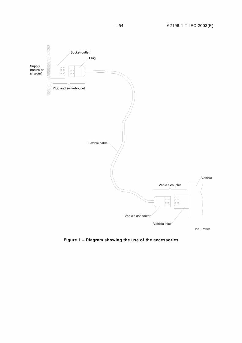
– 54 – 62196-1 IEC:2003(E)
Supply(mains orcharger)
Socket-outlet
Plug
Plug and socket-outlet
Flexible cable
Vehicle coupler
Vehicle
Vehicle connector
Vehicle inletIEC 1202/03
Figure 1 – Diagram showing the use of the accessories
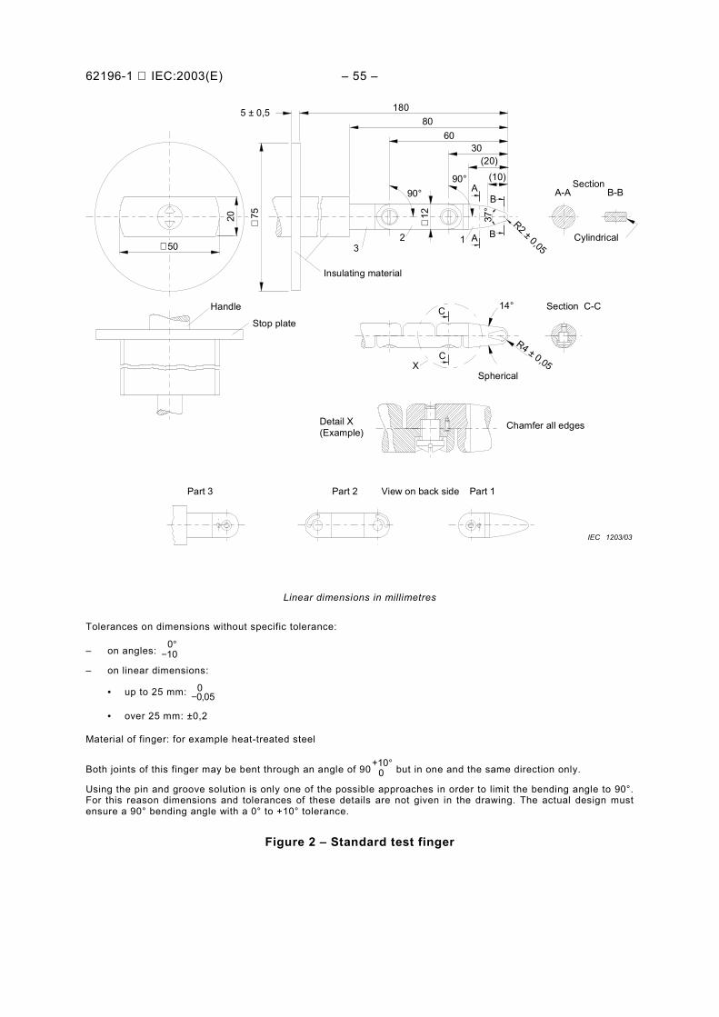
62196-1 IEC:2003(E) – 55 –
∅ 50
20 ∅75
18080
6030
(20)(10)
5 ± 0,5
90°90°
∅12 37
°
A
A B
B
R2 ± 0,0532 1
Insulating material
A-A B-BSection
Cylindrical
C
C
14°
R4 ± 0,05Spherical
Chamfer all edges
Section C-C
Detail X(Example)
Part 3 Part 2 Part 1View on back side
Handle
Stop plate
X
IEC 1203/03
Linear dimensions in millimetres
Tolerances on dimensions without specific tolerance:
– on angles: −°
100
– on linear dimensions:
• up to 25 mm: −0 050,
• over 25 mm: ±0,2
Material of finger: for example heat-treated steel
Both joints of this finger may be bent through an angle of 90 +10
0° but in one and the same direction only.
Using the pin and groove solution is only one of the possible approaches in order to limit the bending angle to 90°.For this reason dimensions and tolerances of these details are not given in the drawing. The actual design mustensure a 90° bending angle with a 0° to +10° tolerance.
Figure 2 – Standard test finger
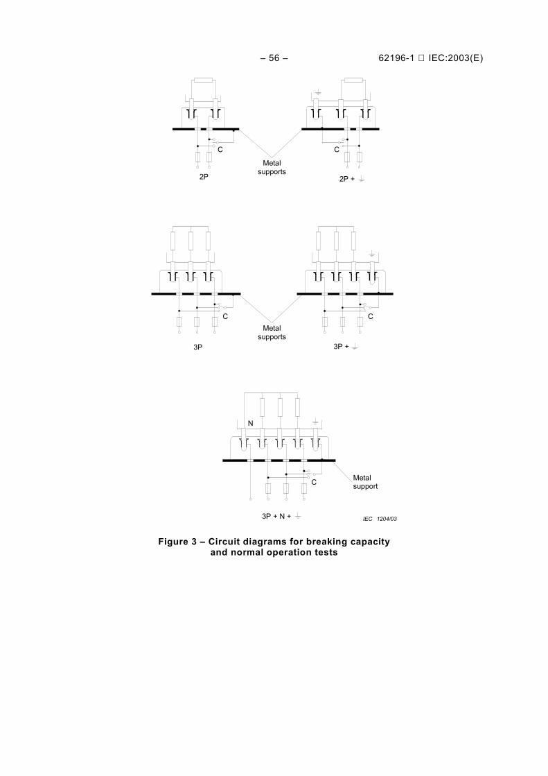
– 56 – 62196-1 IEC:2003(E)
2P 2P +
3P 3P +
3P + N +
C C
C C
C
N
Metalsupports
Metalsupports
Metalsupport
IEC 1204/03
Figure 3 – Circuit diagrams for breaking capacityand normal operation tests
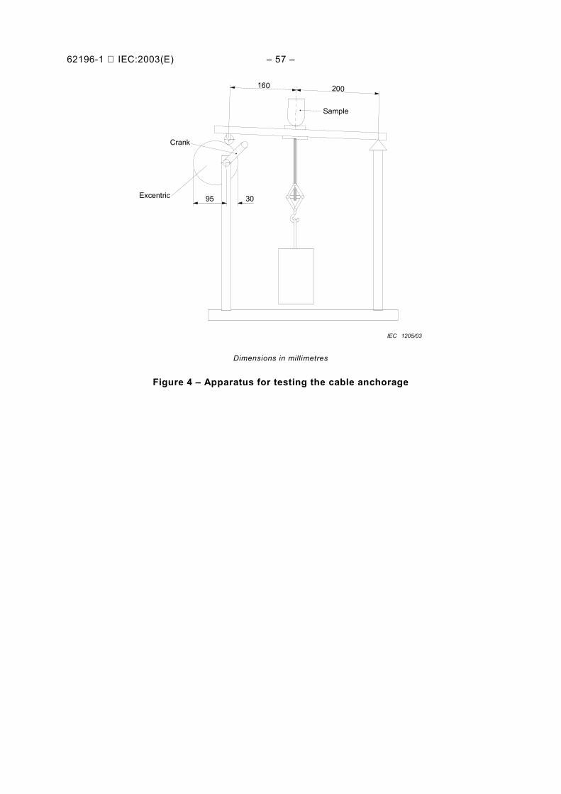
62196-1 IEC:2003(E) – 57 –
Sample
Excentric
Crank
95 30
160 200
IEC 1205/03
Dimensions in millimetres
Figure 4 – Apparatus for testing the cable anchorage
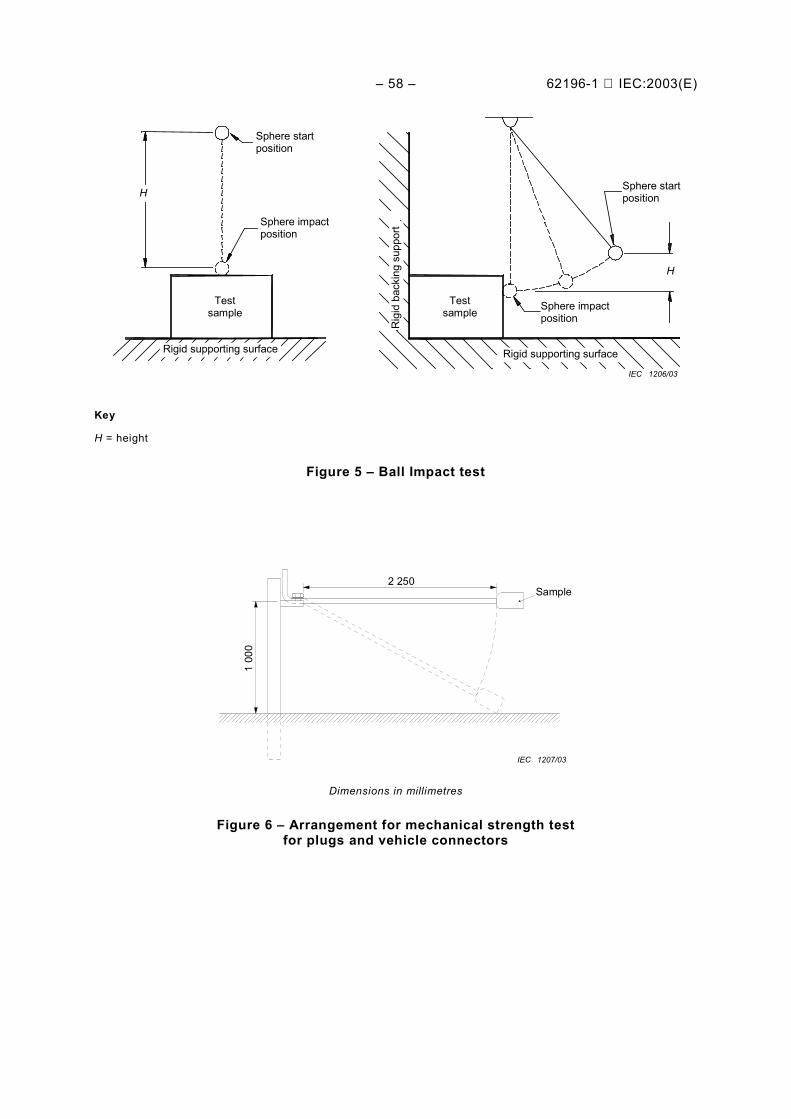
– 58 – 62196-1 IEC:2003(E)
H
H
Sphere startposition
Sphere impactposition
Testsample
Testsample
Rig
id b
acki
ng s
uppo
rt
Rigid supporting surface Rigid supporting surface
Sphere startposition
Sphere impactposition
IEC 1206/03
Key
H = height
Figure 5 – Ball Impact test
2 250Sample
1 00
0
IEC 1207/03
Dimensions in millimetres
Figure 6 – Arrangement for mechanical strength testfor plugs and vehicle connectors
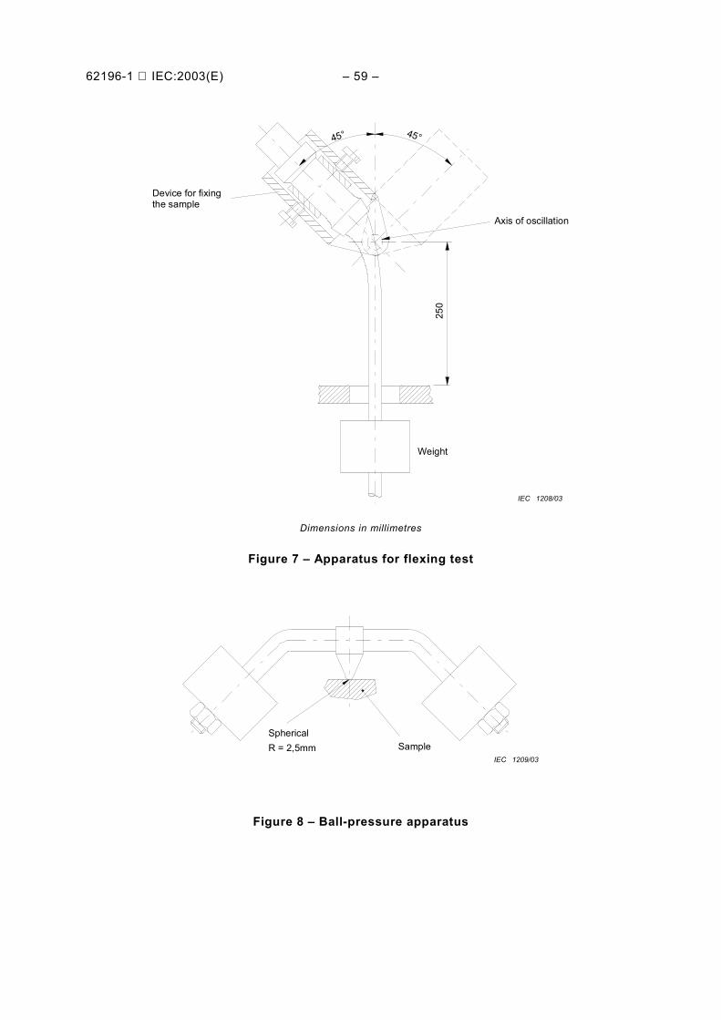
62196-1 IEC:2003(E) – 59 –
Weight
Device for fixingthe sample
Axis of oscillation
45° 45°
250
IEC 1208/03
Dimensions in millimetres
Figure 7 – Apparatus for flexing test
SphericalSampleR = 2,5mm
IEC 1209/03
Figure 8 – Ball-pressure apparatus
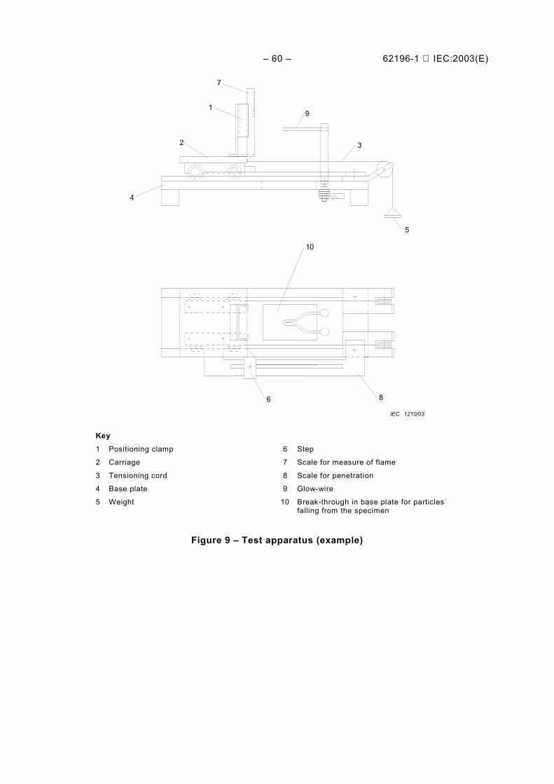
– 60 – 62196-1 IEC:2003(E)
7
1
2
4
9
3
5
10
86
IEC 1210/03
Key1 Positioning clamp
2 Carriage
3 Tensioning cord
4 Base plate
5 Weight
6 Step
7 Scale for measure of flame
8 Scale for penetration
9 Glow-wire
10 Break-through in base plate for particlesfalling from the specimen
Figure 9 – Test apparatus (example)
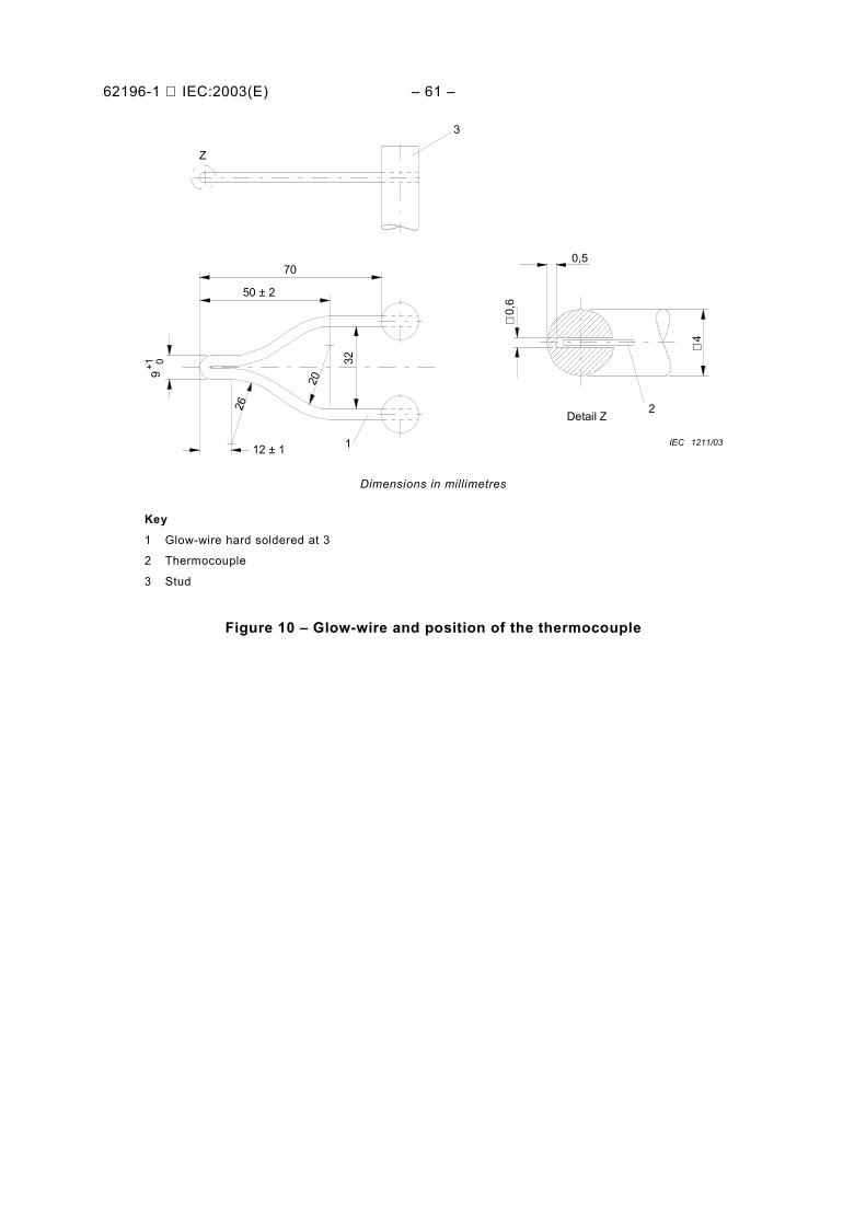
62196-1 IEC:2003(E) – 61 –
9+1 0Z
3
70
50 ± 220
32
26
12 ± 1 1
2
0,5
∅0,
6
∅4
Detail Z
IEC 1211/03
Dimensions in millimetres
Key1 Glow-wire hard soldered at 3
2 Thermocouple
3 Stud
Figure 10 – Glow-wire and position of the thermocouple
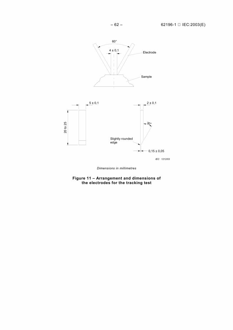
– 62 – 62196-1 IEC:2003(E)
60°
4 ± 0,1
30°
2 ± 0,15 ± 0,1
0,15 ± 0,05
Slightly roundededge
Electrode
Sample
IEC 1212/03
20 to
25
Dimensions in millimetres
Figure 11 – Arrangement and dimensions ofthe electrodes for the tracking test
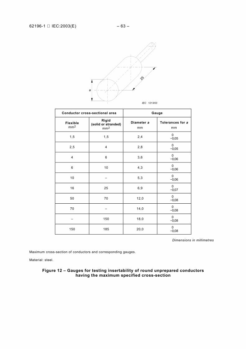
62196-1 IEC:2003(E) – 63 –
a
25
IEC 1213/03
Conductor cross-sectional area Gauge
Flexiblemm2
Rigid(solid or stranded)
mm2
Diameter amm
Tolerances for amm
1,5 1,5 2,4 −0 050
,
2,5 4 2,8 −0 050
,
4 6 3,6 −0 060
,
6 10 4,3 −0 060
,
10 – 5,3 −0 060
,
16 25 6,9 −0 070
,
50 70 12,0 −0 080
,
70 – 14,0 −0 080
,
– 150 18,0 −0 080
,
150 185 20,0 −0 080
,
Dimensions in millimetres
Maximum cross-section of conductors and corresponding gauges.
Material: steel.
Figure 12 – Gauges for testing insertability of round unprepared conductorshaving the maximum specified cross-section
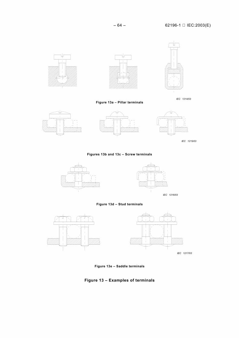
– 64 – 62196-1 IEC:2003(E)
IEC 1214/03Figure 13a – Pillar terminals
IEC 1215/03
Figures 13b and 13c – Screw terminals
IEC 1216/03
Figure 13d – Stud terminals
IEC 1217/03
Figure 13e – Saddle terminals
Figure 13 – Examples of terminals
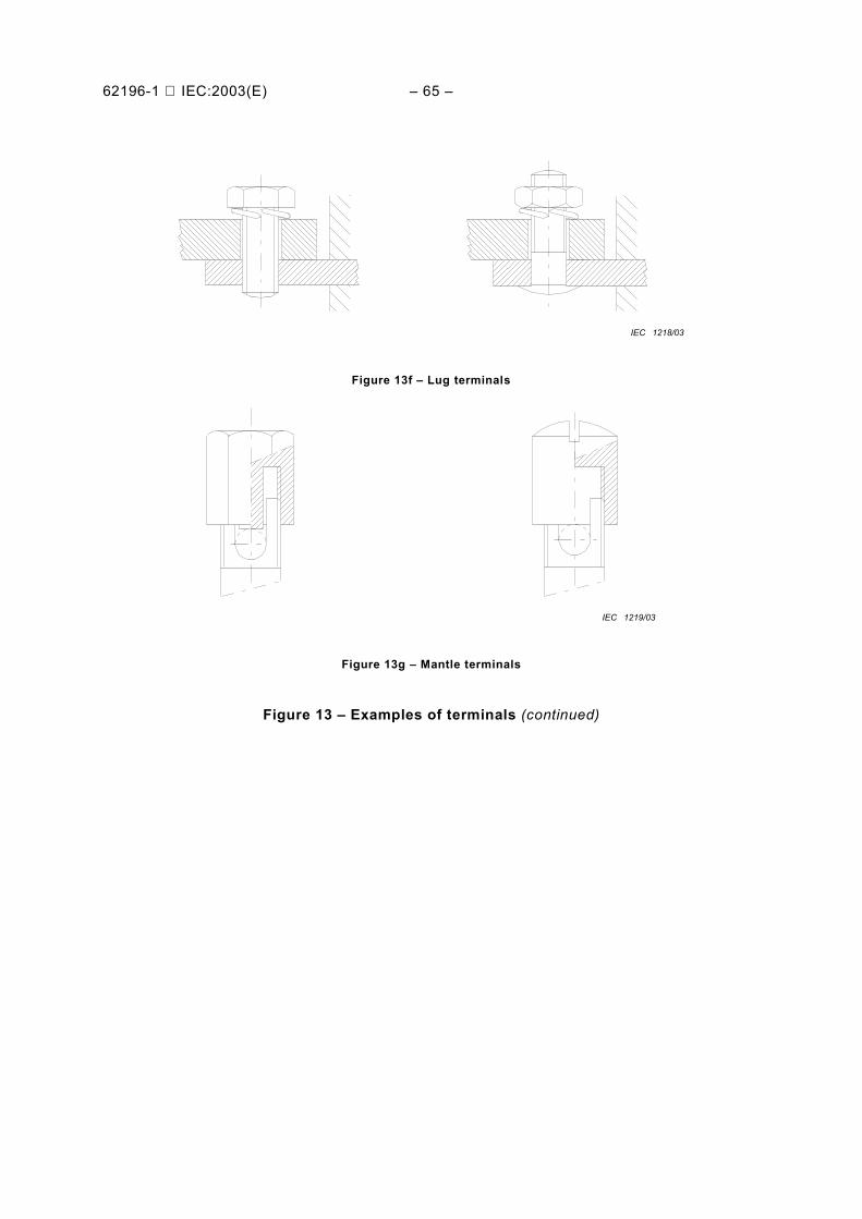
62196-1 IEC:2003(E) – 65 –
IEC 1218/03
Figure 13f – Lug terminals
IEC 1219/03
Figure 13g – Mantle terminals
Figure 13 – Examples of terminals (continued)
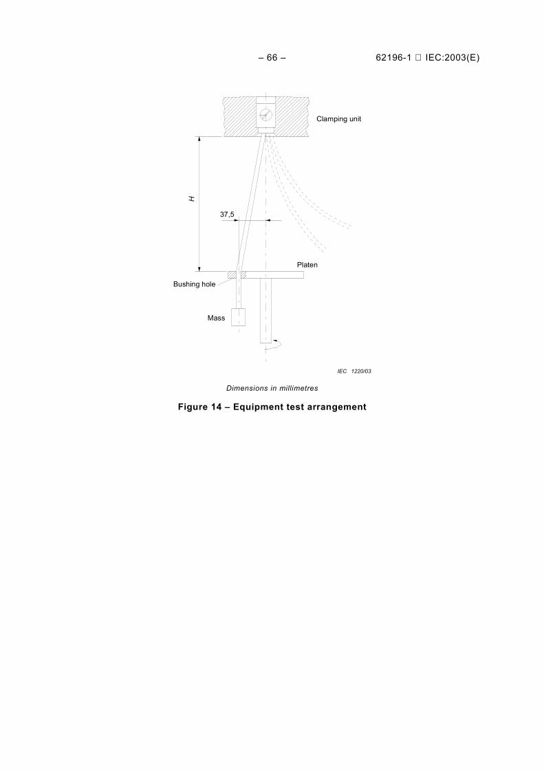
– 66 – 62196-1 IEC:2003(E)
H
37,5
Platen
Mass
Bushing hole
Clamping unit
IEC 1220/03
Dimensions in millimetres
Figure 14 – Equipment test arrangement
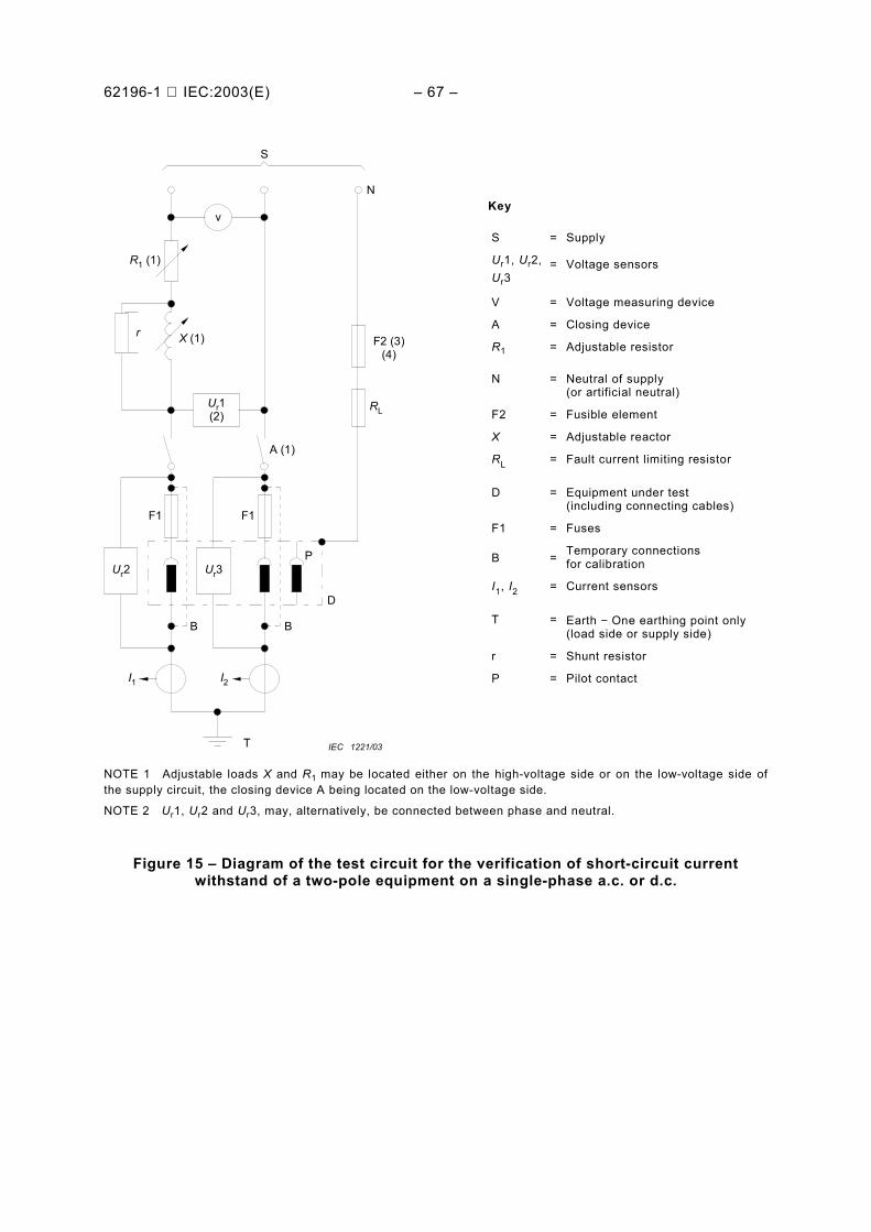
62196-1 IEC:2003(E) – 67 –
S
v
R1 (1)
r X (1)
Ur1(2)
A (1)
F1 F1
Ur2 Ur3P
D
BB
I1 I2
T
RL
F2 (3)(4)
N
IEC 1221/03
NOTE 1 Adjustable loads X and R1 may be located either on the high-voltage side or on the low-voltage side ofthe supply circuit, the closing device A being located on the low-voltage side.
NOTE 2 Ur1, Ur2 and Ur3, may, alternatively, be connected between phase and neutral.
Figure 15 – Diagram of the test circuit for the verification of short-circuit currentwithstand of a two-pole equipment on a single-phase a.c. or d.c.
Key
S = Supply
Ur1, Ur2, =Ur3
Voltage sensors
V = Voltage measuring device
A = Closing device
R1 = Adjustable resistor
N = Neutral of supply(or artificial neutral)
F2 = Fusible element
X = Adjustable reactor
RL = Fault current limiting resistor
D = Equipment under test(including connecting cables)
F1 = Fuses
B = Temporary connectionsfor calibration
I1, I2 = Current sensors
T = Earth − One earthing point only(load side or supply side)
r = Shunt resistor
P = Pilot contact
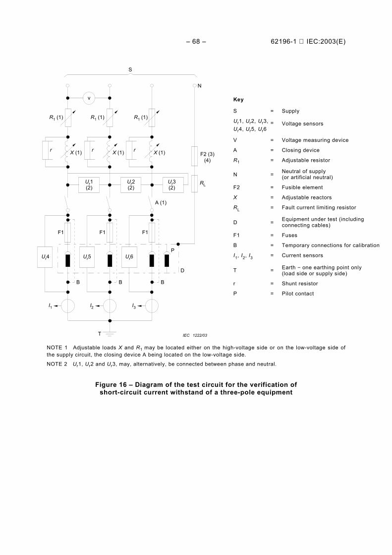
– 68 – 62196-1 IEC:2003(E)
S
v
R1 (1)
r X (1)
Ur1(2)
A (1)
F1 F1
Ur4 Ur5P
D
BB
I1 I2
T
RL
F2 (3)(4)
N
Ur2(2)
Ur3(2)
F1
I3
R1 (1) R1 (1)
X (1) X (1)r r
Ur6
B
IEC 1222/03
NOTE 1 Adjustable loads X and R1 may be located either on the high-voltage side or on the low-voltage side ofthe supply circuit, the closing device A being located on the low-voltage side.
NOTE 2 Ur1, Ur2 and Ur3, may, alternatively, be connected between phase and neutral.
Figure 16 – Diagram of the test circuit for the verification ofshort-circuit current withstand of a three-pole equipment
Key
S = Supply
Ur1, Ur2, Ur3, =Ur4, Ur5, Ur6
Voltage sensors
V = Voltage measuring device
A = Closing device
R1 = Adjustable resistor
N = Neutral of supply(or artificial neutral)
F2 = Fusible element
X = Adjustable reactors
RL = Fault current limiting resistor
D = Equipment under test (includingconnecting cables)
F1 = Fuses
B = Temporary connections for calibration
I1, I2, I3 = Current sensors
T = Earth − one earthing point only(load side or supply side)
r = Shunt resistor
P = Pilot contact
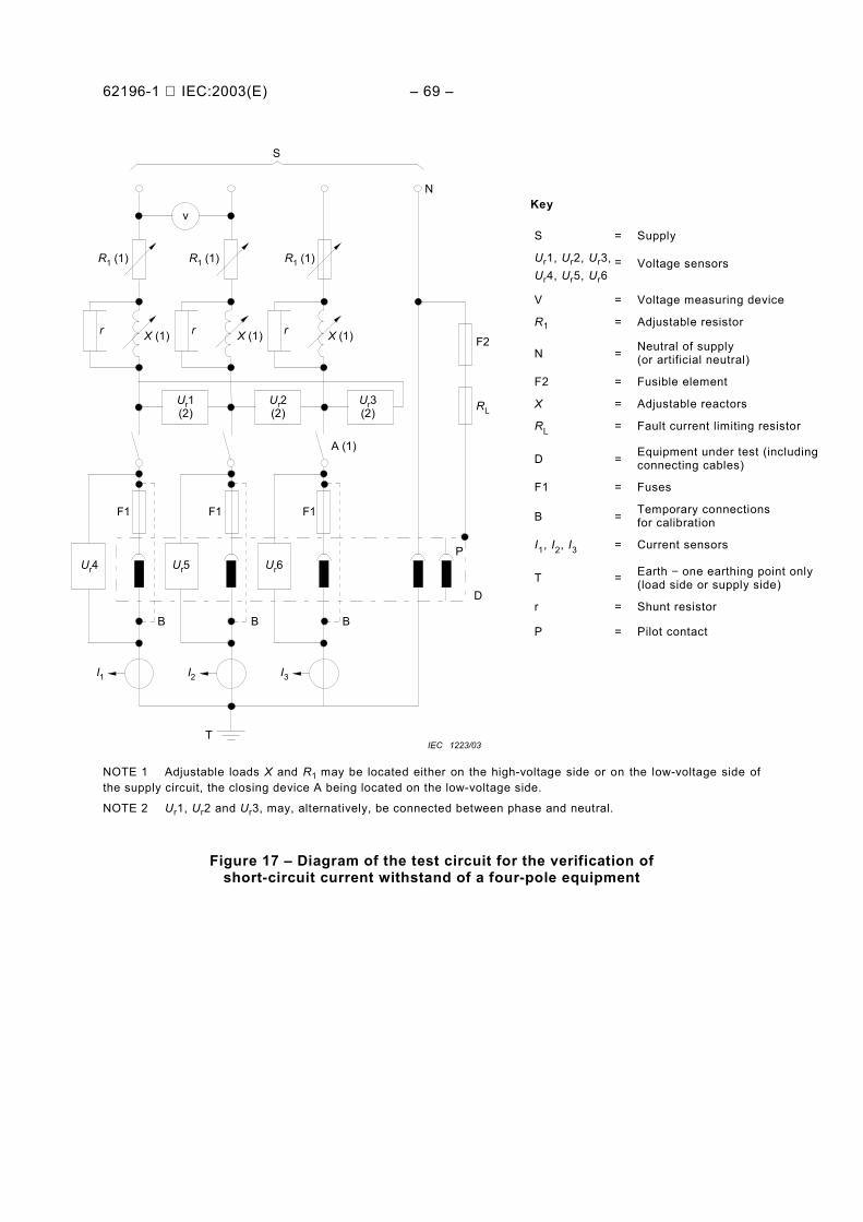
62196-1 IEC:2003(E) – 69 –
S
v
R1 (1)
r X (1)
Ur1(2)
A (1)
F1 F1
Ur4 Ur5
D
BB
I1 I2
T
RL
F2
N
Ur2(2)
Ur3(2)
F1
I3
R1 (1) R1 (1)
X (1) X (1)r r
Ur6P
B
IEC 1223/03
NOTE 1 Adjustable loads X and R1 may be located either on the high-voltage side or on the low-voltage side ofthe supply circuit, the closing device A being located on the low-voltage side.
NOTE 2 Ur1, Ur2 and Ur3, may, alternatively, be connected between phase and neutral.
Figure 17 – Diagram of the test circuit for the verification ofshort-circuit current withstand of a four-pole equipment
Key
S = Supply
Ur1, Ur2, Ur3, =Ur4, Ur5, Ur6
Voltage sensors
V = Voltage measuring device
R1 = Adjustable resistor
N = Neutral of supply(or artificial neutral)
F2 = Fusible element
X = Adjustable reactors
RL = Fault current limiting resistor
D = Equipment under test (includingconnecting cables)
F1 = Fuses
B = Temporary connectionsfor calibration
I1, I2, I3 = Current sensors
T = Earth − one earthing point only(load side or supply side)
r = Shunt resistor
P = Pilot contact
– 70 – 62196-1 IEC:2003(E)
Annex A (informative)
EV charging
A.1 EV Charging Modes
There are four possible modes of charging, as follows.
Mode 1 charging: connection of the EV to the a.c. supply network (mains) utilizingstandardized socket-outlets, rated up to 16 A, at the supply side, single-phase or three-phase,and utilizing phase(s), neutral and protective earth conductors. The use of mode 1 chargingdepends on the presence of a residual current device (RCD) on the supply side. Where thepresence of an RCD on the supply side can not be ensured by national codes, mode 1charging is not permissible.
NOTE 1 In some countries, mode 1 charging may be prohibited by national codes.
NOTE 2 A standardised socket-outlet is one which meets the requirements of any IEC and/or national standard.
NOTE 3 In France, Germany and Italy, the limitation to 16 A for mode 1 charging is not applicable.
Mode 2 charging: connection of the EV to the a.c. supply network (mains) utilizingstandardized socket-outlets, single-phase or three-phase, and utilizing phase(s), neutral, andprotective earth conductors together with a control pilot conductor between the EV and theplug or in-cable control box.
Mode 3 charging: direct connection of the EV to the a.c. supply network (mains) utilizingdedicated EV supply equipment where the control pilot conductor extends to equipmentpermanently connected to the a. c. supply network (mains).
Mode 4 charging: indirect connection of the EV to the a.c. supply network (mains) utilizing anoff-board charger where the control pilot conductor extends to equipment permanentlyconnected to the a.c. supply.
A.2 Types of EV Connection (Cases A, B, and C)
The connection of electric vehicles may be carried out in one or more of three different ways:
Case "A" connection: connection of an EV to the a.c. supply network (mains) utilizinga supply cable and plug permanently attached to the EV.
Case "B" connection: connection of an EV to the a.c. supply network (mains) utilizinga detachable cable assembly with a vehicle connector and a.c. supply equipment.
Case "C" connection: connection of an EV to the a.c. supply network (mains) utilizinga supply cable and vehicle connector permanently attached to the supply equipment. Onlycase "C" is allowed for mode 4 charging.

62196-1 IEC:2003(E) – 71 –
Bibliography
IEC 60050(441):1984, International Electrotechnical Vocabulary (IEV) – Chapter 441: Switch-gear, control gear and fuses.
IEC 60068-2-75:1997, Environmental testing – Part 2-75: Tests – Test Eh: Hammer tests
______________

Standards Survey
The IEC would like to offer you the best quality standards possible. To make sure that wecontinue to meet your needs, your feedback is essential. Would you please take a minuteto answer the questions overleaf and fax them to us at +41 22 919 03 00 or mail them tothe address below. Thank you!
Customer Service Centre (CSC)
International Electrotechnical Commission3, rue de Varembé1211 Genève 20Switzerland
or
Fax to: IEC/CSC at +41 22 919 03 00
Thank you for your contribution to the standards-making process.
Non affrancareNo stamp required
Nicht frankierenNe pas affranchir
A Prioritaire
RÉPONSE PAYÉE
SUISSE
Customer Service Centre (CSC)International Electrotechnical Commission3, rue de Varembé1211 GENEVA 20Switzerland

Q1 Please report on ONE STANDARD andONE STANDARD ONLY . Enter the exactnumber of the standard: (e.g. 60601-1-1)
.............................................................
Q2 Please tell us in what capacity(ies) youbought the standard (tick all that apply).I am the/a:
purchasing agent R
librarian R
researcher R
design engineer R
safety engineer R
testing engineer R
marketing specialist R
other.....................................................
Q3 I work for/in/as a:(tick all that apply)
manufacturing R
consultant R
government R
test/certification facility R
public utility R
education R
military R
other.....................................................
Q4 This standard will be used for:(tick all that apply)
general reference R
product research R
product design/development R
specifications R
tenders R
quality assessment R
certification R
technical documentation R
thesis R
manufacturing R
other.....................................................
Q5 This standard meets my needs:(tick one)
not at all R
nearly R
fairly well R
exactly R
Q6 If you ticked NOT AT ALL in Question 5the reason is: (tick all that apply)
standard is out of date R
standard is incomplete R
standard is too academic R
standard is too superficial R
title is misleading R
I made the wrong choice R
other ....................................................
Q7 Please assess the standard in thefollowing categories, usingthe numbers:(1) unacceptable,(2) below average,(3) average,(4) above average,(5) exceptional,(6) not applicable
timeliness .............................................quality of writing....................................technical contents.................................logic of arrangement of contents ..........tables, charts, graphs, figures ...............other ....................................................
Q8 I read/use the: (tick one)
French text only R
English text only R
both English and French texts R
Q9 Please share any comment on anyaspect of the IEC that you would likeus to know:
............................................................
............................................................
............................................................
............................................................
............................................................
............................................................
............................................................
............................................................
............................................................
............................................................
............................................................
............................................................


ISBN 2-8318-6975-7
-:HSMINB=][^\Z^:ICS 29.120.30; 43.120
Typeset and printed by the IEC Central OfficeGENEVA, SWITZERLAND


![Welcome to the IEC Webstore - INTERNATIONAL STANDARD …ed2.0}b.pdf · 2017. 3. 23. · Welcome to the IEC Webstore - INTERNATIONAL STANDARD NORME INTERNATIONALE ... 9]; ,](https://static.fdocuments.fr/doc/165x107/60b7746d5aeb591938579509/welcome-to-the-iec-webstore-international-standard-ed20bpdf-2017-3-23.jpg)