InRow RD Installation - TUM · 2009-11-06 · 2 InRow Air Cooled RD Installation Safety Note: All...
48
Installation InRow ® RD Air Cooled ACRD100 ACRD101
Transcript of InRow RD Installation - TUM · 2009-11-06 · 2 InRow Air Cooled RD Installation Safety Note: All...
Installation
InRow® RDAir Cooled
ACRD100ACRD101
This manual is available in English on the enclosed CD.
Uživatelská pøíruèka v èeštinì je k dispozici na pøiloženém CD.
Dieses Handbuch ist in Deutsch auf der beiliegenden CD-ROM verfügbar.
Deze handleiding staat in het Nederlands op de bijgevoegde cd.
Este manual está disponible en español en el CD-ROM adjunto.
Ce manuel est disponible en français sur le CD-ROM ci-inclus.
A hasznalati utasitas magyarul megtalalhato a csatolt CD-n.
Questo manuale è disponibile in italiano nel CD-ROM allegato.
本マニュアルの日本語版は同梱の CD-ROM からご覧になれます。
Denne manualen er tilgjengelig på norsk på vedlagte CD.
Instrukcja Obsługi w jezyku polskim jest dostepna na CD.
O manual em Português está disponível no CD-ROM em anexo.
Данное руководство на русском языке имеется на прилагаемом компакт-диске.
Denna manual finns tillgänglig på svenska på medföljande CD.
Bu kullanim kilavuzunun Türkçe'sä, äläxäkte gönderälen CD äçeräsände mevcuttur.
您可以从包含的 CD 上获得本手册的中文版本。
您可以从付属的CD上获得本手册的中文版本。
동봉된 CD 안에 한국어 매뉴얼이 있습니다 .

American Power Conversion Legal DisclaimerThe information presented in this manual is not warranted by the American Power Conversion Corpora-tion to be authoritative, error free, or complete. This publication is not meant to be a substitute for a detailed operational and site specific development plan. Therefore, American Power Conversion Corpo-ration assumes no liability for damages, violations of codes, improper installation, system failures, or any other problems that could arise based on the use of this Publication.
The information contained in this Publication is provided as is and has been prepared solely for the pur-pose of evaluating data center design and construction. This Publication has been compiled in good faith by American Power Conversion Corporation. However, no representation is made or warranty given, either express or implied, as to the completeness or accuracy of the information this Publication contains.
IN NO EVENT SHALL AMERICAN POWER CONVERSION CORPORATION, OR ANY PAR-ENT, AFFILIATE OR SUBSIDIARY COMPANY OF AMERICAN POWER CONVERSION CORPORATION OR THEIR RESPECTIVE OFFICERS, DIRECTORS, OR EMPLOYEES BE LIABLE FOR ANY DIRECT, INDIRECT, CONSEQUENTIAL, PUNITIVE, SPECIAL, OR INCIDENTAL DAMAGES (INCLUDING, WITHOUT LIMITATION, DAMAGES FOR LOSS OF BUSINESS, CONTRACT, REVENUE, DATA, INFORMATION, OR BUSINESS INTER-RUPTION) RESULTING FROM, ARISING OUT, OR IN CONNECTION WITH THE USE OF, OR INABILITY TO USE THIS PUBLICATION OR THE CONTENT, EVEN IF AMERICAN POWER CONVERSION CORPORATION HAS BEEN EXPRESSLY ADVISED OF THE POS-SIBILITY OF SUCH DAMAGES. AMERICAN POWER CONVERSION CORPORATION RESERVES THE RIGHT TO MAKE CHANGES OR UPDATES WITH RESPECT TO OR IN THE CONTENT OF THE PUBLICATION OR THE FORMAT THEREOF AT ANY TIME WITHOUT NOTICE.
Copyright, intellectual, and all other proprietary rights in the content (including but not limited to soft-ware, audio, video, text, and photographs) rests with American Power Conversion Corporation or its licensors. All rights in the content not expressly granted herein are reserved. No rights of any kind are licensed or assigned or shall otherwise pass to persons accessing this information.
This Publication shall not be for resale in whole or in part.

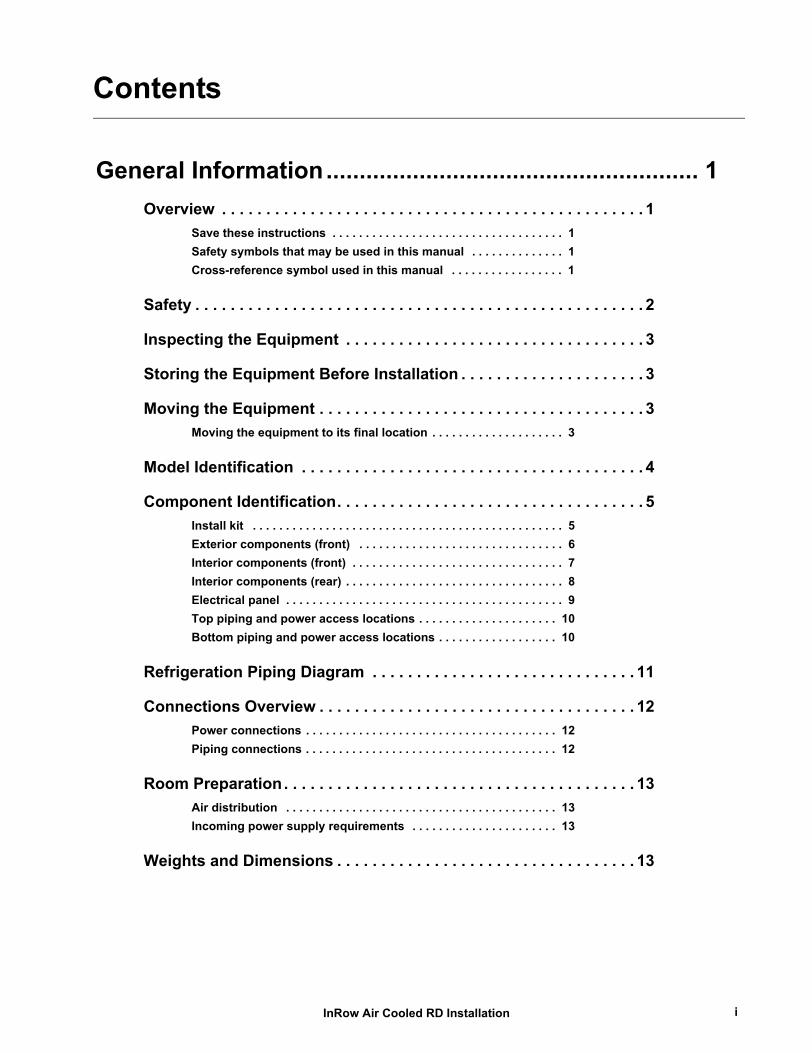
Contents
General Information........................................................ 1Overview . . . . . . . . . . . . . . . . . . . . . . . . . . . . . . . . . . . . . . . . . . . . . . . . 1
Save these instructions . . . . . . . . . . . . . . . . . . . . . . . . . . . . . . . . . . . 1Safety symbols that may be used in this manual . . . . . . . . . . . . . . 1Cross-reference symbol used in this manual . . . . . . . . . . . . . . . . . 1
Safety . . . . . . . . . . . . . . . . . . . . . . . . . . . . . . . . . . . . . . . . . . . . . . . . . . . 2
Inspecting the Equipment . . . . . . . . . . . . . . . . . . . . . . . . . . . . . . . . . . 3
Storing the Equipment Before Installation . . . . . . . . . . . . . . . . . . . . . 3
Moving the Equipment . . . . . . . . . . . . . . . . . . . . . . . . . . . . . . . . . . . . . 3Moving the equipment to its final location . . . . . . . . . . . . . . . . . . . . 3
Model Identification . . . . . . . . . . . . . . . . . . . . . . . . . . . . . . . . . . . . . . . 4
Component Identification. . . . . . . . . . . . . . . . . . . . . . . . . . . . . . . . . . . 5Install kit . . . . . . . . . . . . . . . . . . . . . . . . . . . . . . . . . . . . . . . . . . . . . . . 5Exterior components (front) . . . . . . . . . . . . . . . . . . . . . . . . . . . . . . . 6Interior components (front) . . . . . . . . . . . . . . . . . . . . . . . . . . . . . . . . 7Interior components (rear) . . . . . . . . . . . . . . . . . . . . . . . . . . . . . . . . . 8Electrical panel . . . . . . . . . . . . . . . . . . . . . . . . . . . . . . . . . . . . . . . . . . 9Top piping and power access locations . . . . . . . . . . . . . . . . . . . . . 10Bottom piping and power access locations . . . . . . . . . . . . . . . . . . 10
Refrigeration Piping Diagram . . . . . . . . . . . . . . . . . . . . . . . . . . . . . . 11
Connections Overview . . . . . . . . . . . . . . . . . . . . . . . . . . . . . . . . . . . . 12Power connections . . . . . . . . . . . . . . . . . . . . . . . . . . . . . . . . . . . . . . 12Piping connections . . . . . . . . . . . . . . . . . . . . . . . . . . . . . . . . . . . . . . 12
Room Preparation. . . . . . . . . . . . . . . . . . . . . . . . . . . . . . . . . . . . . . . . 13Air distribution . . . . . . . . . . . . . . . . . . . . . . . . . . . . . . . . . . . . . . . . . 13Incoming power supply requirements . . . . . . . . . . . . . . . . . . . . . . 13
Weights and Dimensions . . . . . . . . . . . . . . . . . . . . . . . . . . . . . . . . . . 13
InRow Air Cooled RD Installation i
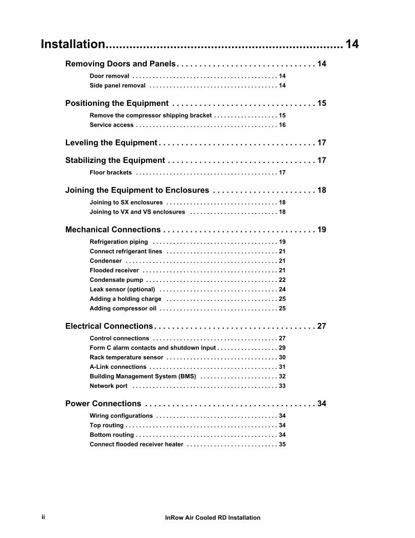
Installation...................................................................... 14Removing Doors and Panels . . . . . . . . . . . . . . . . . . . . . . . . . . . . . . . 14
Door removal . . . . . . . . . . . . . . . . . . . . . . . . . . . . . . . . . . . . . . . . . . . 14Side panel removal . . . . . . . . . . . . . . . . . . . . . . . . . . . . . . . . . . . . . . 14
Positioning the Equipment . . . . . . . . . . . . . . . . . . . . . . . . . . . . . . . . 15Remove the compressor shipping bracket . . . . . . . . . . . . . . . . . . . 15Service access . . . . . . . . . . . . . . . . . . . . . . . . . . . . . . . . . . . . . . . . . . 16
Leveling the Equipment . . . . . . . . . . . . . . . . . . . . . . . . . . . . . . . . . . . 17
Stabilizing the Equipment . . . . . . . . . . . . . . . . . . . . . . . . . . . . . . . . . 17Floor brackets . . . . . . . . . . . . . . . . . . . . . . . . . . . . . . . . . . . . . . . . . . 17
Joining the Equipment to Enclosures . . . . . . . . . . . . . . . . . . . . . . . 18Joining to SX enclosures . . . . . . . . . . . . . . . . . . . . . . . . . . . . . . . . . 18Joining to VX and VS enclosures . . . . . . . . . . . . . . . . . . . . . . . . . . 18
Mechanical Connections . . . . . . . . . . . . . . . . . . . . . . . . . . . . . . . . . . 19Refrigeration piping . . . . . . . . . . . . . . . . . . . . . . . . . . . . . . . . . . . . . 19Connect refrigerant lines . . . . . . . . . . . . . . . . . . . . . . . . . . . . . . . . . 21Condenser . . . . . . . . . . . . . . . . . . . . . . . . . . . . . . . . . . . . . . . . . . . . . 21Flooded receiver . . . . . . . . . . . . . . . . . . . . . . . . . . . . . . . . . . . . . . . . 21Condensate pump . . . . . . . . . . . . . . . . . . . . . . . . . . . . . . . . . . . . . . . 22Leak sensor (optional) . . . . . . . . . . . . . . . . . . . . . . . . . . . . . . . . . . . 24Adding a holding charge . . . . . . . . . . . . . . . . . . . . . . . . . . . . . . . . . 25Adding compressor oil . . . . . . . . . . . . . . . . . . . . . . . . . . . . . . . . . . . 25
Electrical Connections. . . . . . . . . . . . . . . . . . . . . . . . . . . . . . . . . . . . 27Control connections . . . . . . . . . . . . . . . . . . . . . . . . . . . . . . . . . . . . . 27Form C alarm contacts and shutdown input . . . . . . . . . . . . . . . . . . 29Rack temperature sensor . . . . . . . . . . . . . . . . . . . . . . . . . . . . . . . . . 30A-Link connections . . . . . . . . . . . . . . . . . . . . . . . . . . . . . . . . . . . . . . 31Building Management System (BMS) . . . . . . . . . . . . . . . . . . . . . . . 32Network port . . . . . . . . . . . . . . . . . . . . . . . . . . . . . . . . . . . . . . . . . . . 33
Power Connections . . . . . . . . . . . . . . . . . . . . . . . . . . . . . . . . . . . . . . 34Wiring configurations . . . . . . . . . . . . . . . . . . . . . . . . . . . . . . . . . . . . 34Top routing . . . . . . . . . . . . . . . . . . . . . . . . . . . . . . . . . . . . . . . . . . . . . 34Bottom routing . . . . . . . . . . . . . . . . . . . . . . . . . . . . . . . . . . . . . . . . . . 34Connect flooded receiver heater . . . . . . . . . . . . . . . . . . . . . . . . . . . 35
InRow Air Cooled RD Installationii
Warranty .........................................................................36One-Year Factory Warranty . . . . . . . . . . . . . . . . . . . . . . . . . . . . . . . .36
Terms of warranty . . . . . . . . . . . . . . . . . . . . . . . . . . . . . . . . . . . . . . . 36Non-transferable warranty . . . . . . . . . . . . . . . . . . . . . . . . . . . . . . . . 36Exclusions . . . . . . . . . . . . . . . . . . . . . . . . . . . . . . . . . . . . . . . . . . . . . 36Warranty claims . . . . . . . . . . . . . . . . . . . . . . . . . . . . . . . . . . . . . . . . . 37
Warranty Procedures . . . . . . . . . . . . . . . . . . . . . . . . . . . . . . . . . . . . .38Claims . . . . . . . . . . . . . . . . . . . . . . . . . . . . . . . . . . . . . . . . . . . . . . . . . 38Parts . . . . . . . . . . . . . . . . . . . . . . . . . . . . . . . . . . . . . . . . . . . . . . . . . . 38
InRow Air Cooled RD Installation iii


General Information
OverviewSave these instructions
This manual contains important instructions that must be followed during the installation of this equipment.
Safety symbols that may be used in this manual
Electrical Hazard: Indicates an electrical hazard which, if not avoided, could result in injury or death.
Danger: Indicates a hazard which, if not avoided, could result in severe personal injury or death.
Warning: Indicates a hazard which, if not avoided, could result in personal injury or damage to product or other property.
Heavy: Indicates a heavy load that should not be lifted without assistance.
Caution: Indicates a potential hazard which, if not avoided, could result in damage to the equipment or other property.
Tip Hazard: This equipment is easily tipped. Use extreme caution when unpacking or moving.
Note: Indicates important information.
Cross-reference symbol used in this manual
See another section of this document or another document for more information on this subject.
1InRow Air Cooled RD Installation
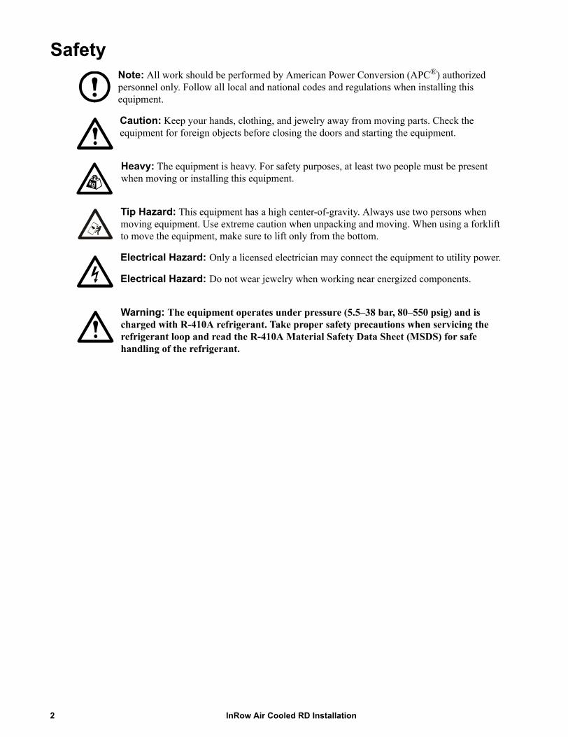
Safety Note: All work should be performed by American Power Conversion (APC®) authorized personnel only. Follow all local and national codes and regulations when installing this equipment.
Caution: Keep your hands, clothing, and jewelry away from moving parts. Check the equipment for foreign objects before closing the doors and starting the equipment.
Heavy: The equipment is heavy. For safety purposes, at least two people must be present when moving or installing this equipment.
Tip Hazard: This equipment has a high center-of-gravity. Always use two persons when moving equipment. Use extreme caution when unpacking and moving. When using a forklift to move the equipment, make sure to lift only from the bottom.
Electrical Hazard: Only a licensed electrician may connect the equipment to utility power.
Electrical Hazard: Do not wear jewelry when working near energized components.
Warning: The equipment operates under pressure (5.5–38 bar, 80–550 psig) and is charged with R-410A refrigerant. Take proper safety precautions when servicing the refrigerant loop and read the R-410A Material Safety Data Sheet (MSDS) for safe handling of the refrigerant.
InRow Air Cooled RD Installation2

Inspecting the EquipmentYour American Power Conversion (APC®) InRowTM RD air conditioner has been tested and inspected for quality assurance before shipment from APC. Carefully inspect both the exterior and interior of the equipment immediately upon receipt to ensure that the equipment has not been damaged during transit.
Verify that all parts ordered were received as specified and that the equipment is the correct type, size, and voltage.
Filing a claim. If damage is identified on receipt of the equipment, note the damage on the bill of lading and file a damage claim with the shipping company. Contact APC Worldwide Customer Support at one of the numbers listed on the back cover of this manual for information about filing a claim with the shipping company. The shipping claim must be filed at the receiving end of the delivery.
Note: In case of shipping damage, do not operate the equipment. Keep all packaging for inspection by the shipping company.
Storing the Equipment Before InstallationIf the equipment will not be installed immediately, store it in a safe place, protected from the weather.
Caution: Leaving the equipment uncovered and exposed to possible damage from the environment will void the factory warranty.
Moving the EquipmentMoving the equipment to its final location
The recommended tools for moving the equipment while it is still on the pallet include the following:
Tip Hazard: The equipment can be rolled to its final location using its casters if the floor is smooth and clean. Be sure two people move the equipment.
Pallet jack Forklift
3InRow Air Cooled RD Installation

Model IdentificationThe model number can be found on the outside of the shipping crate and on the nameplate located on the rear of the equipment as shown. Use the table below to verify that the equipment is the correct type and voltage.
Model Configuration Voltage Air Pattern
ACRD100 Air-cooled 208-240/1~/60 Hz Back to front
ACRD101 Air-cooled 220-240/1~/50 Hz Back to front
na26
90a
Nameplate
InRow Air Cooled RD Installation4
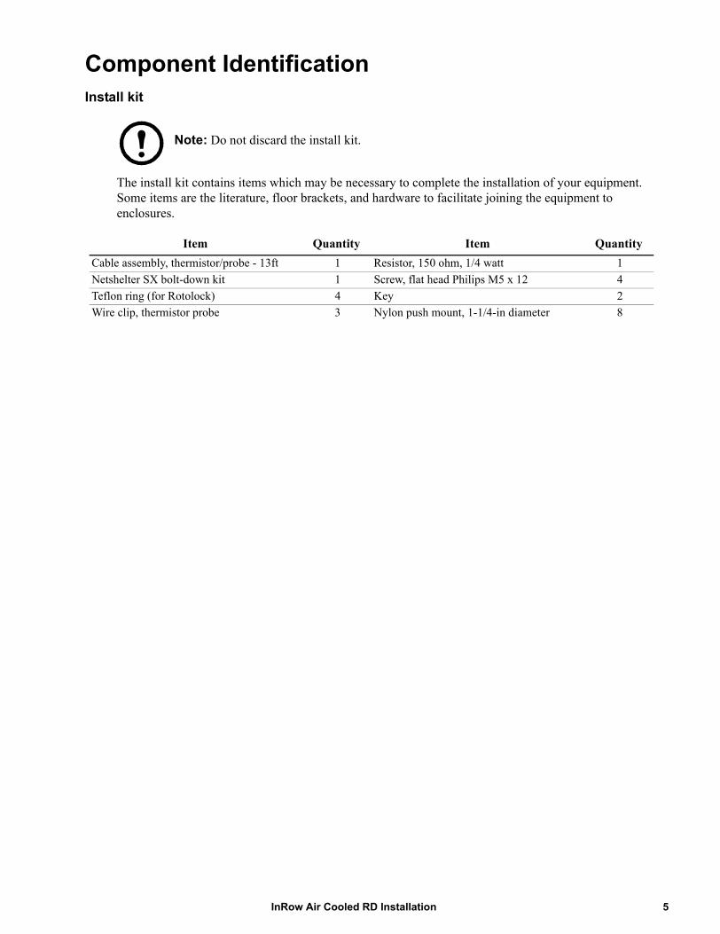
Component IdentificationInstall kit
Note: Do not discard the install kit.
The install kit contains items which may be necessary to complete the installation of your equipment. Some items are the literature, floor brackets, and hardware to facilitate joining the equipment to enclosures.
Item Quantity Item QuantityCable assembly, thermistor/probe - 13ft 1 Resistor, 150 ohm, 1/4 watt 1Netshelter SX bolt-down kit 1 Screw, flat head Philips M5 x 12 4Teflon ring (for Rotolock) 4 Key 2Wire clip, thermistor probe 3 Nylon push mount, 1-1/4-in diameter 8
5InRow Air Cooled RD Installation

Exterior components (front)
Removable rear door Adjustable leveling foot
Side panel latch Display interface
Removable side panel Removable front door
Rear casters (non-swiveling)
Door lock
Front casters (swiveling)
na26
25a
InRow Air Cooled RD Installation6
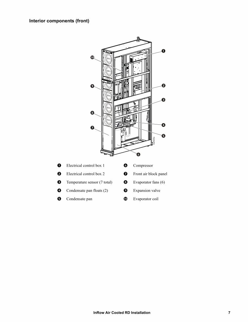
Interior components (front)
Electrical control box 1 Compressor
Electrical control box 2 Front air block panel
Temperature sensor (7 total) Evaporator fans (6)
Condensate pan floats (2) Expansion valve
Condensate pan Evaporator coil
na26
26a
7InRow Air Cooled RD Installation

Interior components (rear)
Filter/dryer Hot gas bypass valve
Pressure transducer (2) (located behind air block)
Liquid line shutoff solenoid
Filter differential pressure port Electrical control box 1
Air filter (2) Power supply unit #2
Condensate pump (2) Power supply unit #1
Electrical contol box 2 Service junction box (top entry shown)
Sight glass
na26
27a
InRow Air Cooled RD Installation8
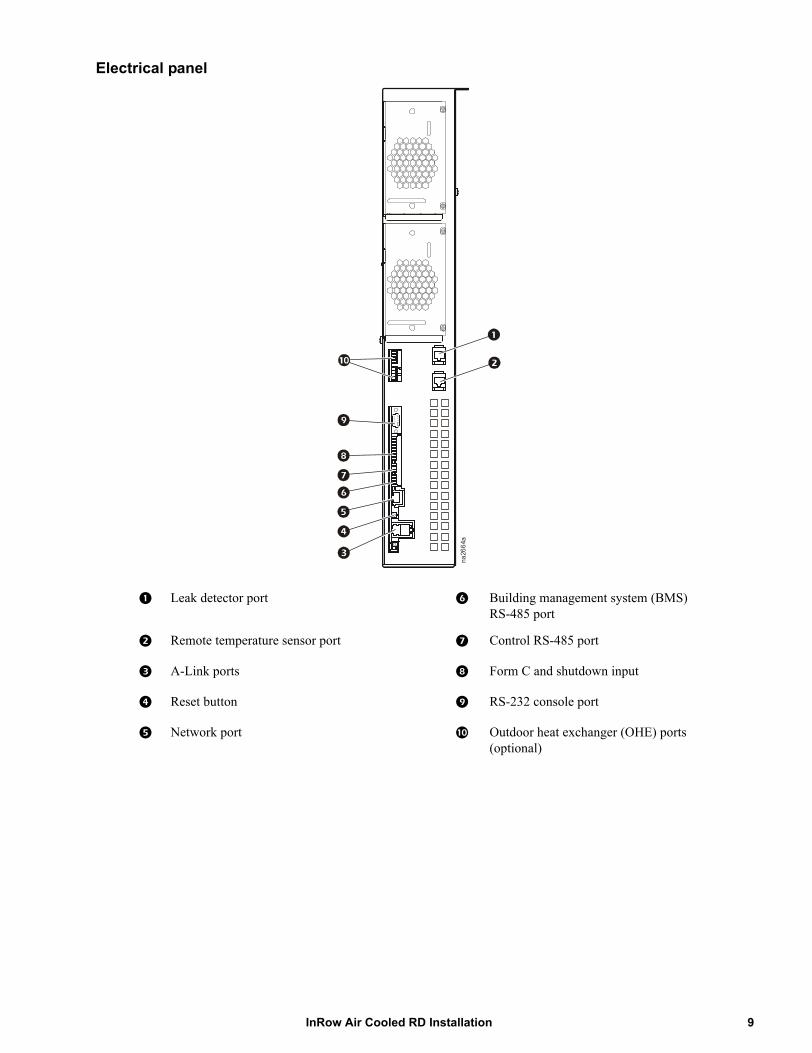
Electrical panel
Leak detector port Building management system (BMS) RS-485 port
Remote temperature sensor port Control RS-485 port
A-Link ports Form C and shutdown input
Reset button RS-232 console port
Network port Outdoor heat exchanger (OHE) ports (optional)
na26
64a
9InRow Air Cooled RD Installation
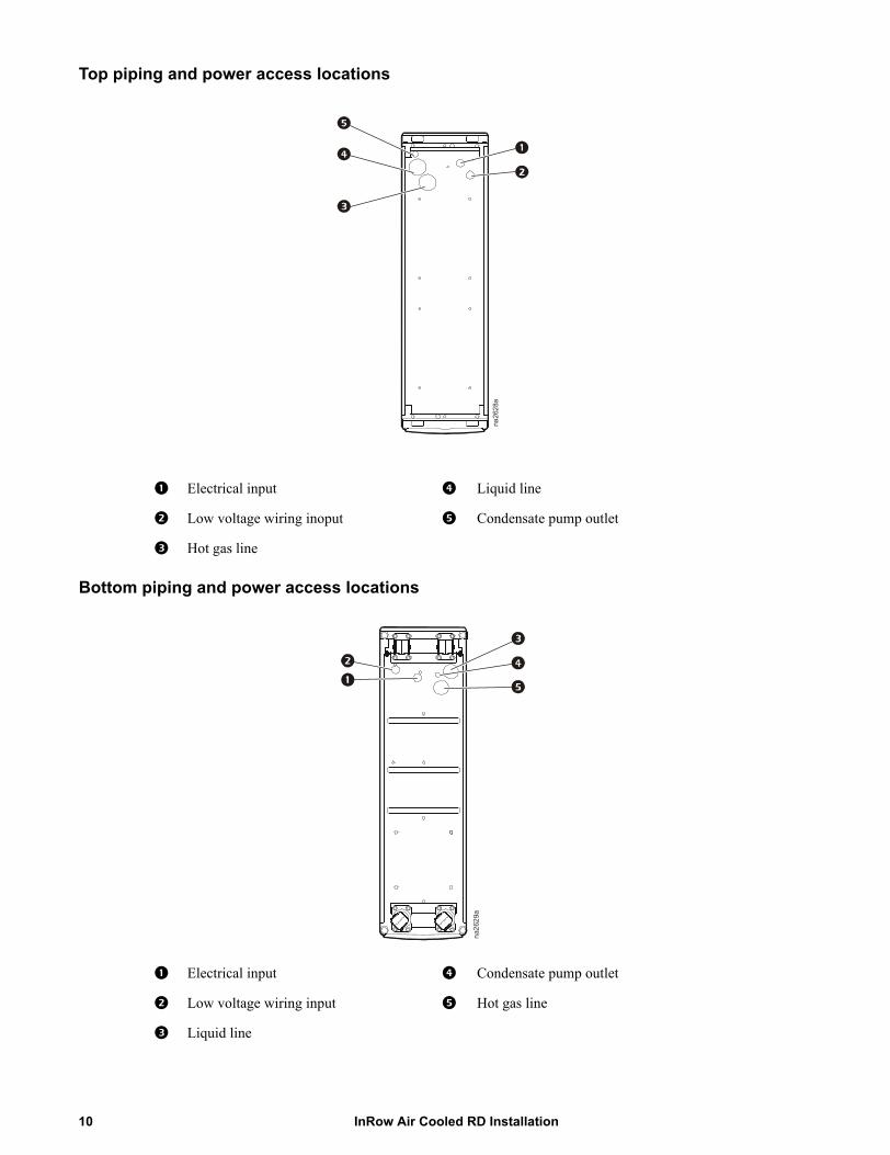
Top piping and power access locations
Bottom piping and power access locations
Electrical input Liquid line
Low voltage wiring inoput Condensate pump outlet
Hot gas line
Electrical input Condensate pump outlet
Low voltage wiring input Hot gas line
Liquid line
na26
28a
na26
29a
InRow Air Cooled RD Installation10
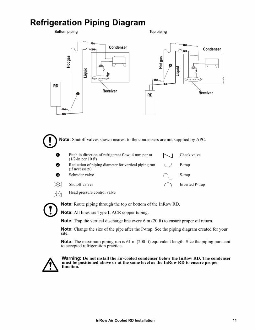
Refrigeration Piping Diagram
Note: Shutoff valves shown nearest to the condensers are not supplied by APC.
Note: Route piping through the top or bottom of the InRow RD.
Note: All lines are Type L ACR copper tubing.
Note: Trap the vertical discharge line every 6 m (20 ft) to ensure proper oil return.
Note: Change the size of the pipe after the P-trap. See the piping diagram created for your site.
Note: The maximum piping run is 61 m (200 ft) equivalent length. Size the piping pursuant to accepted refrigeration practice.
Warning: Do not install the air-cooled condenser below the InRow RD. The condenser must be positioned above or at the same level as the InRow RD to ensure proper function.
Pitch in direction of refrigerant flow; 4 mm per m (1/2-in per 10 ft)
Check valve
Reduction of piping diameter for vertical piping run (if necessary)
P-trap
Schrader valve S-trap
Shutoff valves Inverted P-trap
Head pressure control valve
na25
43a
H ot g
as
L iqu
id H ot g
as
RD
RDReceiver Receiver
Bottom piping Top piping
Condenser Condenser
Liqu
i d
11InRow Air Cooled RD Installation
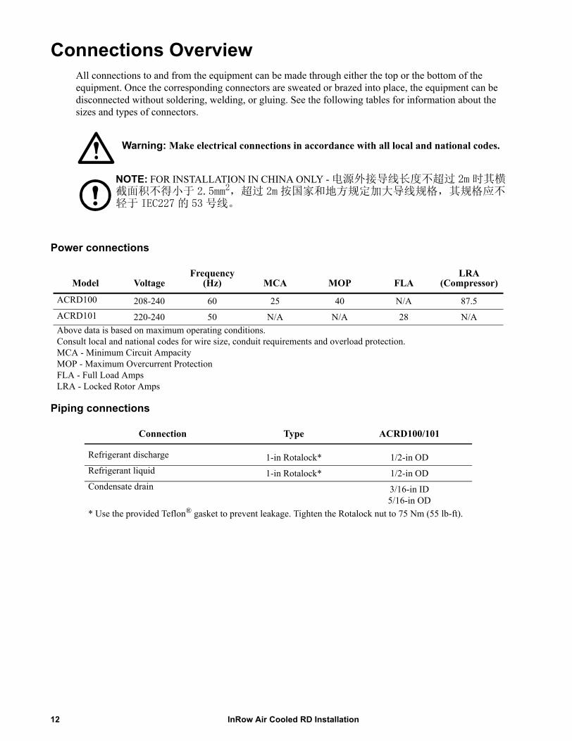
Connections OverviewAll connections to and from the equipment can be made through either the top or the bottom of the equipment. Once the corresponding connectors are sweated or brazed into place, the equipment can be disconnected without soldering, welding, or gluing. See the following tables for information about the sizes and types of connectors.
Warning: Make electrical connections in accordance with all local and national codes.
NOTE: FOR INSTALLATION IN CHINA ONLY - 电源外接导线长度不超过 2m 时其横截面积不得小于 2.5mm2,超过 2m 按国家和地方规定加大导线规格,其规格应不轻于 IEC227 的 53 号线。
Power connections
Piping connections
Model VoltageFrequency
(Hz) MCA MOP FLALRA
(Compressor)
ACRD100 208-240 60 25 40 N/A 87.5ACRD101 220-240 50 N/A N/A 28 N/AAbove data is based on maximum operating conditions.Consult local and national codes for wire size, conduit requirements and overload protection.MCA - Minimum Circuit AmpacityMOP - Maximum Overcurrent ProtectionFLA - Full Load AmpsLRA - Locked Rotor Amps
Connection Type ACRD100/101
Refrigerant discharge 1-in Rotalock* 1/2-in ODRefrigerant liquid 1-in Rotalock* 1/2-in ODCondensate drain 3/16-in ID
5/16-in OD* Use the provided Teflon® gasket to prevent leakage. Tighten the Rotalock nut to 75 Nm (55 lb-ft).
InRow Air Cooled RD Installation12

Room PreparationAir distribution
The equipment distributes air in a back-to-front discharge pattern, removing hot air from a hot aisle and discharging cooled air into a cold aisle.
Note: The equipment is designed for free air discharge or for use with the Rack Air Containment System or Hot Aisle Containment System. The equipment is not intended to be connected to a duct system.
Incoming power supply requirements
Electrical Hazard: Electrical service must conform to local and national electrical codes and regulations. The equipment must be grounded.
Weights and Dimensions
Dimensions are shown in mm (in).
Model Packed weight Unpacked weight
ACRD100, ACRD101 221 kg (488 lb) 183 kg (404 lb)
na22
31a
13InRow Air Cooled RD Installation
Installation
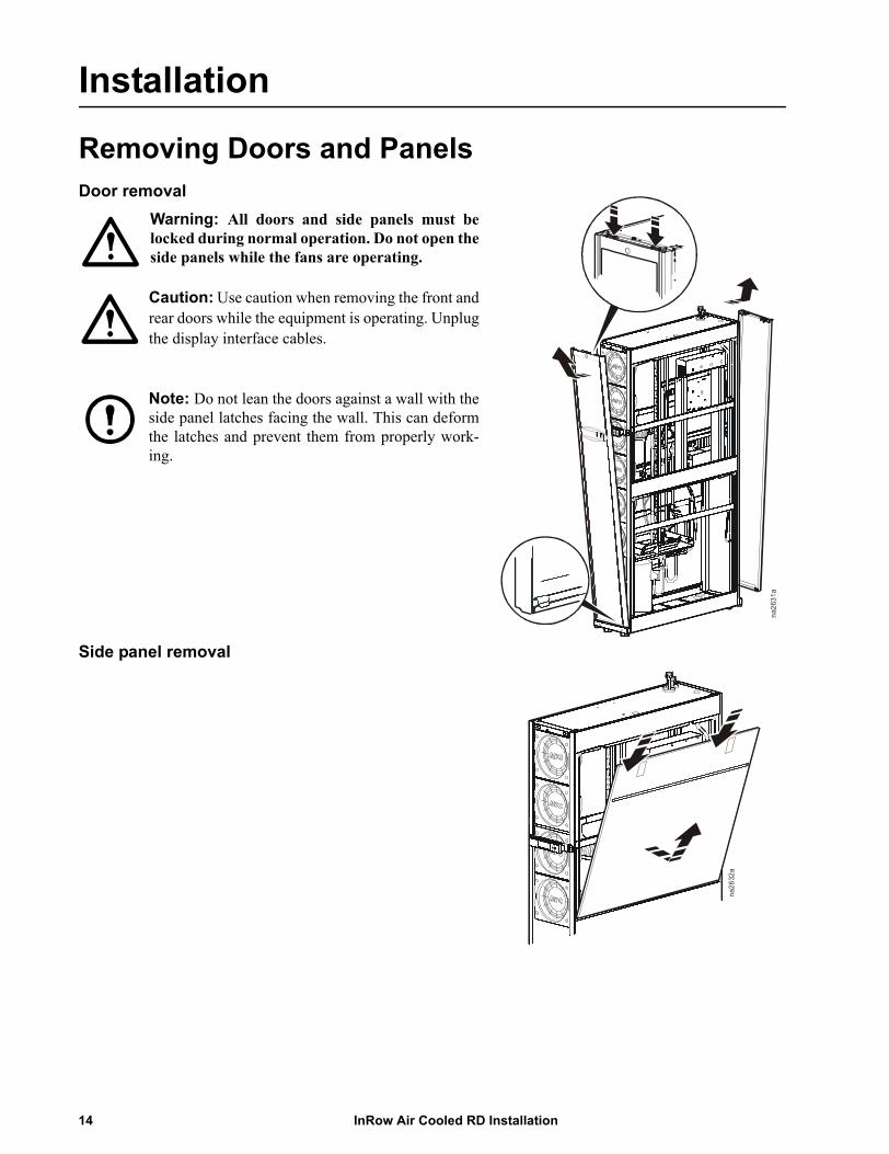
Removing Doors and PanelsDoor removal
Side panel removal
na26
31a
Warning: All doors and side panels must belocked during normal operation. Do not open theside panels while the fans are operating.
Caution: Use caution when removing the front andrear doors while the equipment is operating. Unplugthe display interface cables.
Note: Do not lean the doors against a wall with theside panel latches facing the wall. This can deformthe latches and prevent them from properly work-ing.
na26
32a
InRow Air Cooled RD Installation14

Positioning the EquipmentRemove the compressor shipping bracket
Caution: Failure to complete the following steps may result in equipment damage and will void your warranty.
The compressor is secured by a bracket to prevent damage during shipping. This bracket must be removed before you apply power to the equipment.
1. Remove two T30 Torx screws from the bracket as shown. Save the screws for possible future use.2. Remove the bracket and save for possible future use.
na26
91a
Remove screws
Remove bracket
15InRow Air Cooled RD Installation
Service access
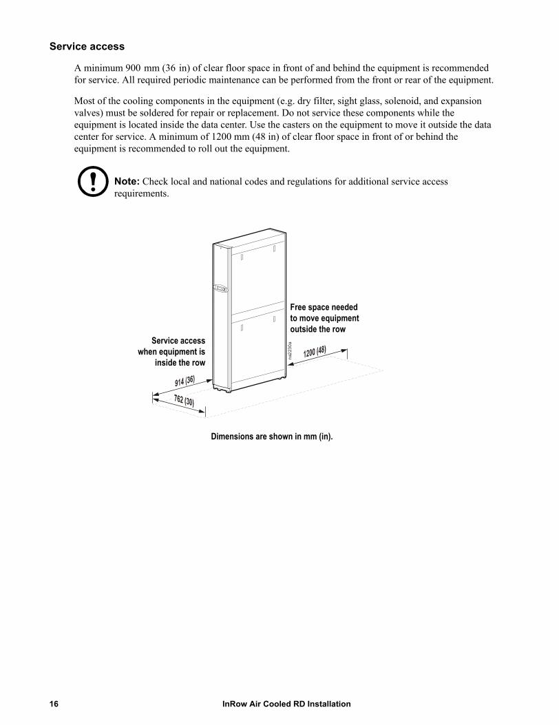
A minimum 900 mm (36 in) of clear floor space in front of and behind the equipment is recommended for service. All required periodic maintenance can be performed from the front or rear of the equipment.
Most of the cooling components in the equipment (e.g. dry filter, sight glass, solenoid, and expansion valves) must be soldered for repair or replacement. Do not service these components while the equipment is located inside the data center. Use the casters on the equipment to move it outside the data center for service. A minimum of 1200 mm (48 in) of clear floor space in front of or behind the equipment is recommended to roll out the equipment.
Note: Check local and national codes and regulations for additional service access requirements.
Dimensions are shown in mm (in).
na22
30aService access
when equipment isinside the row
Free space needed to move equipment outside the row
InRow Air Cooled RD Installation16
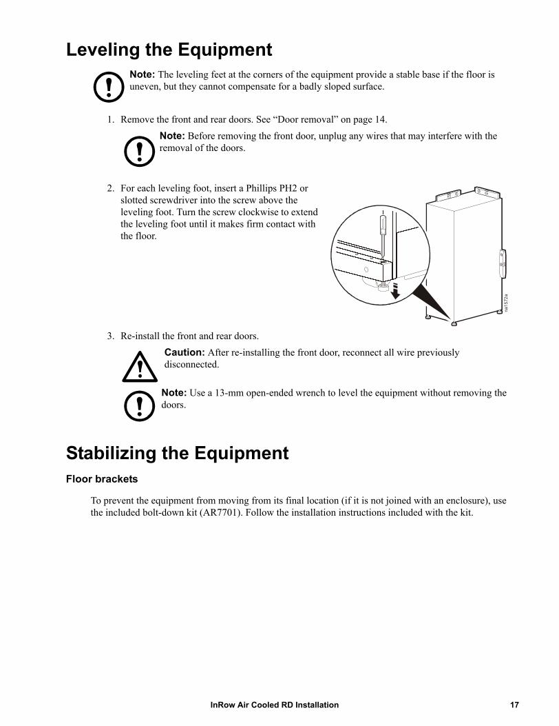
Leveling the EquipmentNote: The leveling feet at the corners of the equipment provide a stable base if the floor is uneven, but they cannot compensate for a badly sloped surface.
1. Remove the front and rear doors. See “Door removal” on page 14.Note: Before removing the front door, unplug any wires that may interfere with the removal of the doors.
2. For each leveling foot, insert a Phillips PH2 or slotted screwdriver into the screw above the leveling foot. Turn the screw clockwise to extend the leveling foot until it makes firm contact with the floor.
3. Re-install the front and rear doors.Caution: After re-installing the front door, reconnect all wire previously disconnected.
Note: Use a 13-mm open-ended wrench to level the equipment without removing the doors.
Stabilizing the EquipmentFloor brackets
To prevent the equipment from moving from its final location (if it is not joined with an enclosure), use the included bolt-down kit (AR7701). Follow the installation instructions included with the kit.
na15
72a
17InRow Air Cooled RD Installation
Joining the Equipment to EnclosuresJoining to SX enclosures
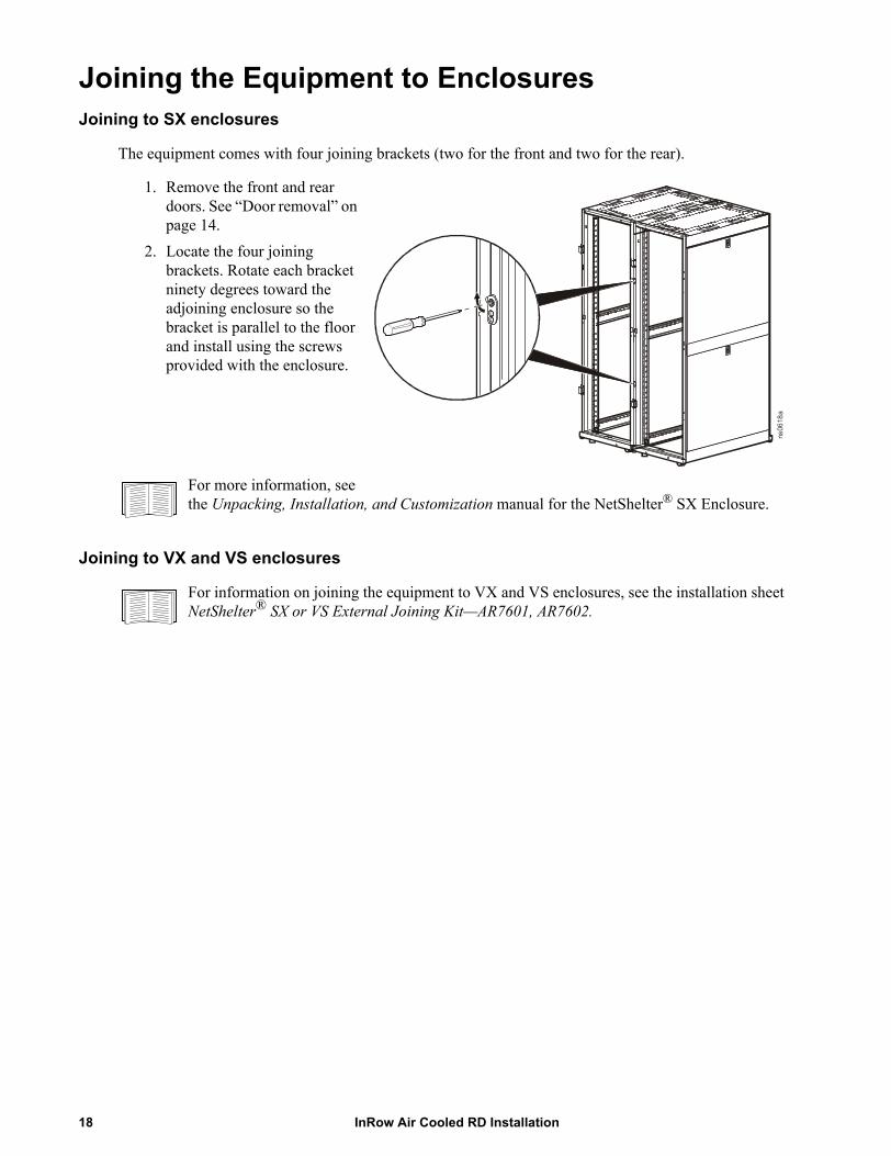
The equipment comes with four joining brackets (two for the front and two for the rear).
1. Remove the front and rear doors. See “Door removal” on page 14.
2. Locate the four joining brackets. Rotate each bracket ninety degrees toward the adjoining enclosure so the bracket is parallel to the floor and install using the screws provided with the enclosure.
For more information, see the Unpacking, Installation, and Customization manual for the NetShelter® SX Enclosure.
Joining to VX and VS enclosures
For information on joining the equipment to VX and VS enclosures, see the installation sheet NetShelter® SX or VS External Joining Kit—AR7601, AR7602.
ns06
18a
InRow Air Cooled RD Installation18
Mechanical ConnectionsRefrigeration piping
The equipment must be connected to a condenser—either a remote outdoor condenser or an indoor centrifugal condenser. Systems with remote outdoor or indoor centrifugal condensers will require discharge and liquid lines from the equipment to the condenser. Install all refrigerant lines in accordance with applicable industry guidelines as well as local and national codes and regulations.
To size lines, see “Recommended line sizes” on page 20.
Calculate an equivalent length based on the actual linear length of the run, including valves and fittings.
Note: All fittings should be long-radius to minimize pressure drop.
Discharge lines are sized such that velocity in vertical lines is between 5 m/s (1000 ft/min) and 15 m/s(3000 ft/m). Limit the velocity in horizontal lines to 2.5 m/s (500 ft/min). The refrigerant velocity must be high enough to keep oil entrained in the flow. If it is too low, oil will not return to the compressor. If the refrigerant velocity is too high, both the noise level and pressure drop will increase. Pressure drops of up to 0.7 bar (10 psi) in discharge lines are acceptable.
Note: Fully loaded, the nominal cooling capacity of the equipment is 10 kW. At its lowest speed, the equipment cooling capacity is approximately 2 kW. Note: Give consideration to the loaded and unloaded state of the compressor to ensure that the operational range stays within these limits.Note: Change the size of the pipe before the P-trap. See “Refrigeration Piping Diagram” on page 11.
Make all refrigerant lines as short and direct as possible. Horizontal discharge lines must a minimum downward pitch of 4 mm per m (1/2 in per 10 ft) in the flow direction to aid in oil return. Install traps in the vertical discharge lines approximately every 6 m (20 ft) to ensure proper oil return. Traps are normally not necessary at the base of discharge lines; however, loop the line to the floor before running it vertically to prevent the drainage of oil back to the compressor during shutdown periods.
Isolate piping from structural surfaces using vibration clamps.
Note: Install all piping in accordance with applicable industry guidelines as well as local and national codes and regulations.
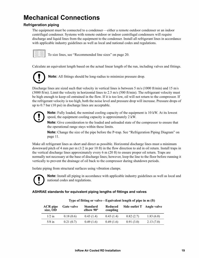
ASHRAE standards for equivalent piping lengths of fittings and valves
Type of fitting or valve—Equivalent length of pipe in m (ft)
ACR pipe size, OD
Gate valve Standard elbow 90°
Reduced coupling
Side outlet T Angle valve
1/2 in 0.18 (0.6) 0.43 (1.4) 0.43 (1.4) 0.82 (2.7) 1.83 (6.0)
5/8 in 0.21 (0.7) 0.49 (1.6) 0.49 (1.6) 0.91 (3.0) 2.13 (7.0)
19InRow Air Cooled RD Installation
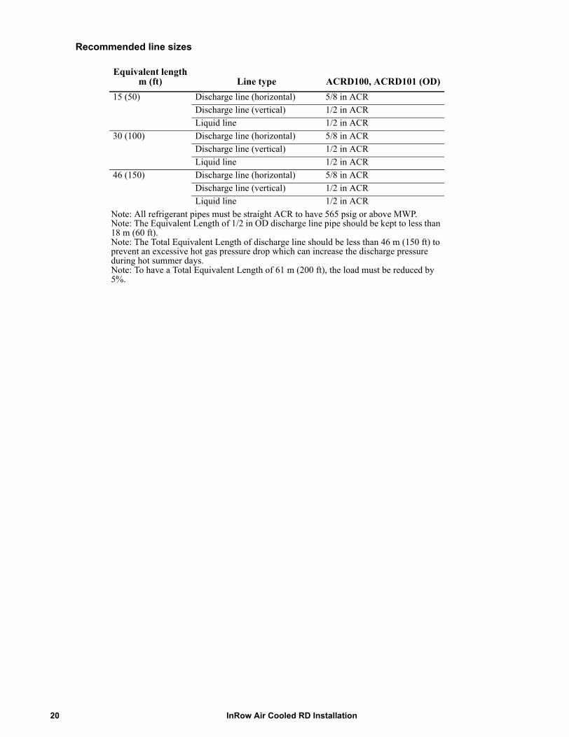
Recommended line sizes
Equivalent length m (ft) Line type ACRD100, ACRD101 (OD)
15 (50) Discharge line (horizontal) 5/8 in ACRDischarge line (vertical) 1/2 in ACRLiquid line 1/2 in ACR
30 (100) Discharge line (horizontal) 5/8 in ACRDischarge line (vertical) 1/2 in ACRLiquid line 1/2 in ACR
46 (150) Discharge line (horizontal) 5/8 in ACRDischarge line (vertical) 1/2 in ACRLiquid line 1/2 in ACR
Note: All refrigerant pipes must be straight ACR to have 565 psig or above MWP.Note: The Equivalent Length of 1/2 in OD discharge line pipe should be kept to less than 18 m (60 ft).Note: The Total Equivalent Length of discharge line should be less than 46 m (150 ft) to prevent an excessive hot gas pressure drop which can increase the discharge pressure during hot summer days.Note: To have a Total Equivalent Length of 61 m (200 ft), the load must be reduced by 5%.
InRow Air Cooled RD Installation20
Connect refrigerant lines
Be sure to use only clean, refrigerant-grade (ACR Type L) pipe and follow standard procedures for pipe size selection for air-cooled equipment. The maximum allowable equivalent length between the evaporator and condenser is 61 equivalent m (200 equivalent ft). Vertical runs (hot gas) require a trap every 6 m (20 ft) of rise.
Note: When brazing field-installed copper refrigeration lines, use a nitrogen purge to minimize contamination of the refrigeration system during the brazing process.
The air-cooled equipment has been dehydrated at the factory and is shipped with a holding charge of 207 kPa (30 psig) nitrogen. Test refrigerant connections for leaks before replacing the holding charge.
Connect both refrigerant lines to the equipment, using provided fittings. See “Install kit” on page 5.
Condenser
Install and pipe the condenser in accordance with the provided instructions.
Flooded receiver
Install the flooded receiver in accordance with the instructions included with the kit.
Note: Install a 3/8" Schrader port on the liquid line outlet of the flooded receiver, approximately 152 mm (6 in) downstream of the service port.
21InRow Air Cooled RD Installation
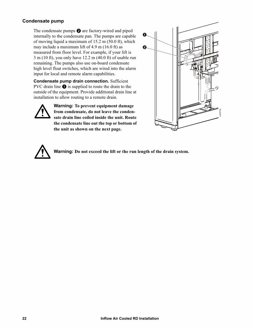
Condensate pump
The condensate pumps are factory-wired and piped internally to the condensate pan. The pumps are capable of moving liquid a maximum of 15.2 m (50.0 ft), which may include a maximum lift of 4.9 m (16.0 ft) as measured from floor level. For example, if your lift is 3 m (10 ft), you only have 12.2 m (40.0 ft) of usable run remaining. The pumps also use on-board condensate high level float switches, which are wired into the alarm input for local and remote alarm capabilities.Condensate pump drain connection. Sufficient PVC drain line is supplied to route the drain to the outside of the equipment. Provide additional drain line at installation to allow routing to a remote drain.
Warning: Do not exceed the lift or the run length of the drain system.
na26
70a
Warning: To prevent equipment damage from condensate, do not leave the conden-sate drain line coiled inside the unit. Route the condensate line out the top or bottom of the unit as shown on the next page.
InRow Air Cooled RD Installation22
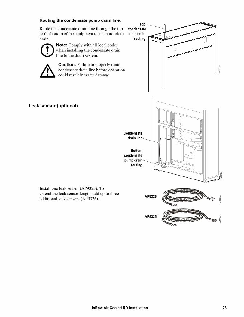
Routing the condensate pump drain line.
Route the condensate drain line through the top or the bottom of the equipment to an appropriate drain.
Leak sensor (optional)
Install one leak sensor (AP9325). To extend the leak sensor length, add up to three additional leak sensors (AP9326).
na26
71a
Topcondensatepump drain
routingNote: Comply with all local codes when installing the condensate drain line to the drain system.
Caution: Failure to properly route condensate drain line before operation could result in water damage.
na26
72a
Condensatedrain line
Bottomcondensatepump drain
routing
na15
84a
na27
60aAP9325
AP9325
23InRow Air Cooled RD Installation
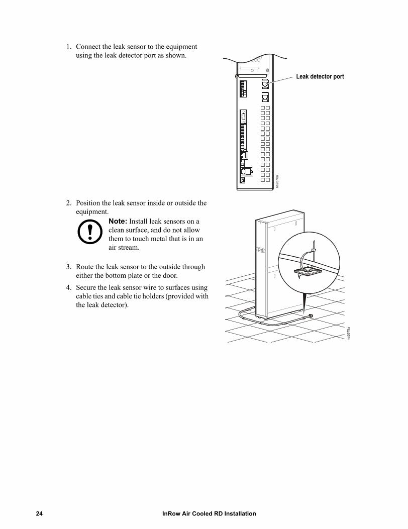
1. Connect the leak sensor to the equipment using the leak detector port as shown.
2. Position the leak sensor inside or outside the equipment.
3. Route the leak sensor to the outside through either the bottom plate or the door.
4. Secure the leak sensor wire to surfaces using cable ties and cable tie holders (provided with the leak detector).
na26
76a
Leak detector port
na26
75a
Note: Install leak sensors on a clean surface, and do not allow them to touch metal that is in an air stream.
InRow Air Cooled RD Installation24
Adding a holding charge
R-410A is a mixed refrigerant. When charging this equipment with mixed refrigerant, only liquid refrigerant must be charged.
Caution: Failure to charge with liquid refrigerant only may damage the system.
Note: The equipment must be charged only with R-410A. It is the responsibility of the installing contractor to provide sufficient refrigerant for a complete system charge during start-up.
Note: It is very important to make a note of the amount of R-410A used in this pre-charge.
Note: It is recommended that the isolation valve assembly accessory (ACAC10022) be installed to facilitate moving the equipment after installation.
1. If installed, open the two shutoff valves above or below the equipment. Do not close the valves unless there is a need to remove the incoming piping.
2. Pressurize the system to 17.2 bar (250 psi) with nitrogen. Leave the system pressurized for 24 hours (recommended), and then check the gauges for a drop in pressure.
3. Use a deep vacuum pump and pull the first vacuum down to 750 microns. Wait for an hour (vacuum should not rise above 1500 microns) and then break the vacuum with nitrogen.
4. Pull a final vacuum down to 300 microns for a minimum of 2 hours. Caution: Install a ball valve before the micron gauge to prevent damage to the micron gauge during charging.
5. Using the charging table, calculate the total charge needed, then charge to 80% of that total. See “Charging Table” on page 26.
6. Record the amount of refrigerant used so the charge can be completed later.
7. Charge with liquid R-410A until the system pressure equalizes with the refrigerant canister. a. Apply the charge into the liquid line service port inside the equipment.b. Purge the refrigerant hoses and manifold set.
Adding compressor oil
Depending upon piping run lengths, the system may require an additional charge of oil at start-up. The installing contractor shall provide adequate compressor (POE) oil.
25InRow Air Cooled RD Installation
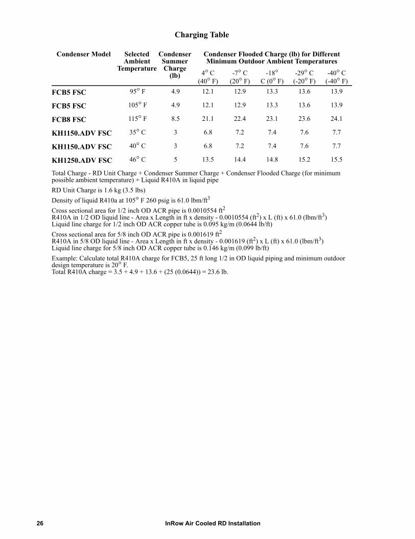
Charging Table
Condenser Model Selected Ambient
Temperature
Condenser Summer Charge
(lb)
Condenser Flooded Charge (lb) for Different Minimum Outdoor Ambient Temperatures
4° C(40° F)
-7° C(20° F)
-18° C (0° F)
-29° C(-20° F)
-40° C(-40° F)
FCB5 FSC 95° F 4.9 12.1 12.9 13.3 13.6 13.9
FCB5 FSC 105° F 4.9 12.1 12.9 13.3 13.6 13.9
FCB8 FSC 115° F 8.5 21.1 22.4 23.1 23.6 24.1
KH1150.ADV FSC 35° C 3 6.8 7.2 7.4 7.6 7.7
KH1150.ADV FSC 40° C 3 6.8 7.2 7.4 7.6 7.7
KH1250.ADV FSC 46° C 5 13.5 14.4 14.8 15.2 15.5
Total Charge - RD Unit Charge + Condenser Summer Charge + Condenser Flooded Charge (for minimum possible ambient temperature) + Liquid R410A in liquid pipeRD Unit Charge is 1.6 kg (3.5 lbs)Density of liquid R410a at 105° F 260 psig is 61.0 lbm/ft3
Cross sectional area for 1/2 inch OD ACR pipe is 0.0010554 ft2R410A in 1/2 OD liquid line - Area x Length in ft x density - 0.0010554 (ft2) x L (ft) x 61.0 (lbm/ft3)Liquid line charge for 1/2 inch OD ACR copper tube is 0.095 kg/m (0.0644 lb/ft)Cross sectional area for 5/8 inch OD ACR pipe is 0.001619 ft2R410A in 5/8 OD liquid line - Area x Length in ft x density - 0.001619 (ft2) x L (ft) x 61.0 (lbm/ft3)Liquid line charge for 5/8 inch OD ACR copper tube is 0.146 kg/m (0.099 lb/ft)Example: Calculate total R410A charge for FCB5, 25 ft long 1/2 in OD liquid piping and minimum outdoor design temperature is 20° F. Total R410A charge = 3.5 + 4.9 + 13.6 + (25 (0.0644)) = 23.6 lb.
InRow Air Cooled RD Installation26
Electrical ConnectionsThe electrical connections required in the field are:
• Controls (display interface, Network Management Card)• Communication (A-Link, Building Management System)• Power to InRow RD (single phase plus ground)• Power to flooded receiver heater
All electrical connections must be in accordance with applicable industry guidelines as well as national and local codes and regulations.
See the equipment nameplate for voltage and current requirements.Make all low-voltage connections, including data and control connections, with properly insulated wires. Insulation of low-voltage wiring must be rated for at least the voltage of any adjacent wiring.
Electrical Hazard: Potentially dangerous and lethal voltages exist within this equipment. More than one disconnect switch may be required to energize or de-energize this equipment. Observe all cautions and warnings. Failure to do so could result in serious injury or death. Only qualified service and maintenance personnel may work on this equipment.
Electrical Hazard: The equipment must be grounded. Check the equipment nameplate for correct ratings.
Warning: Use a voltmeter to ensure that power is turned off before making any electrical connections.
NOTE: FOR INSTALLATION IN CHINA ONLY - 至少需要一个不小于 3mm 触点开距的全极断开装置,以便对此设备进行通电和断电。
Control connections
Note: Wire all low voltage input and output connections as Class 2 circuits.
Depending on the configuration, additional control connections may be required for the A-Link remote communications through APC Network Management Card support or traditional equipment-monitoring software.
27InRow Air Cooled RD Installation
User interface connections
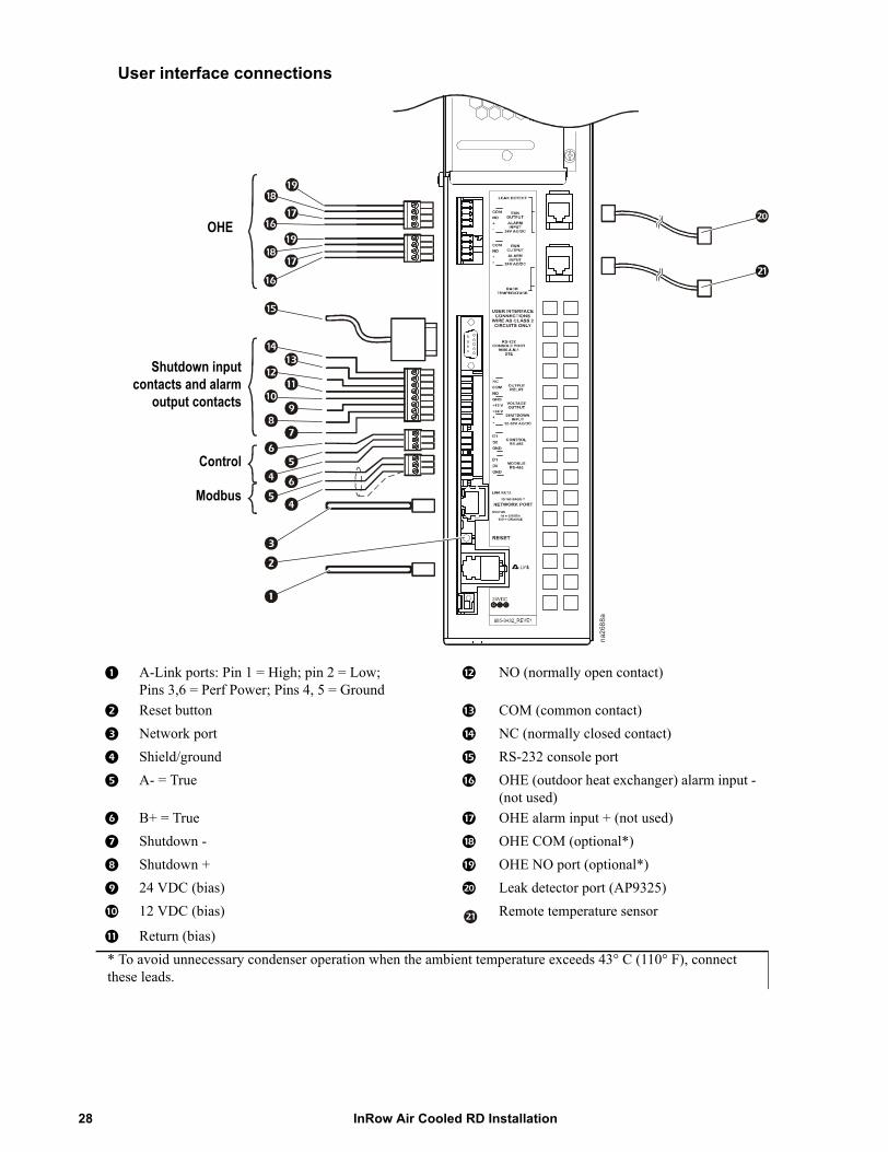
A-Link ports: Pin 1 = High; pin 2 = Low; Pins 3,6 = Perf Power; Pins 4, 5 = Ground
NO (normally open contact)
Reset button COM (common contact)
Network port NC (normally closed contact)
Shield/ground RS-232 console port
A- = True OHE (outdoor heat exchanger) alarm input - (not used)
B+ = True OHE alarm input + (not used)
Shutdown - OHE COM (optional*)
Shutdown + OHE NO port (optional*)
24 VDC (bias) Leak detector port (AP9325)
12 VDC (bias) Remote temperature sensor
Return (bias)* To avoid unnecessary condenser operation when the ambient temperature exceeds 43° C (110° F), connect these leads.
na26
88a
Shutdown inputcontacts and alarm
output contacts
Control
Modbus
OHE
InRow Air Cooled RD Installation28

Form C alarm contacts and shutdown input
See items 6 through 13 in “User interface connections” on page 28. A relay internal to the user interface is controlled by a user-defined alarm (for example, malfunctioning fans). Before an alarm condition, the signal on the COM (common) terminal is routed to the NC (normally closed) terminal. When the alarm is activated, the relay is energized, causing the signal on the COM terminal to be routed to the NO (normally open) terminal. The NO and NC terminals could be connected to remote indicator lights, a warning buzzer, or another device to alert an operator to the presence of an alarm condition.
A remote disconnect switch can be connected to the shutdown inputs as shown.
Note: Either +12 VDC or +24 VDC can be used to power the remote disconnect.
na22
50a
Remotedisconnect
switch
29InRow Air Cooled RD Installation
Rack temperature sensor
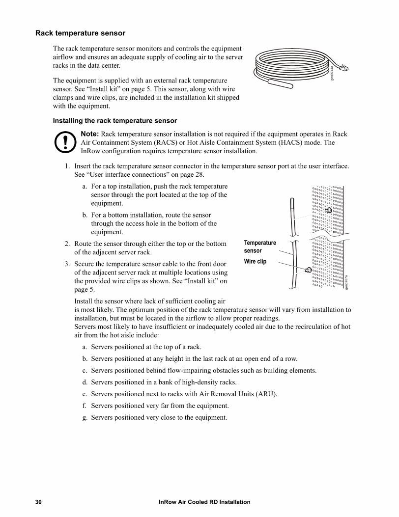
The rack temperature sensor monitors and controls the equipment airflow and ensures an adequate supply of cooling air to the server racks in the data center.
The equipment is supplied with an external rack temperature sensor. See “Install kit” on page 5. This sensor, along with wire clamps and wire clips, are included in the installation kit shipped with the equipment.
Installing the rack temperature sensor
Note: Rack temperature sensor installation is not required if the equipment operates in Rack Air Containment System (RACS) or Hot Aisle Containment System (HACS) mode. The InRow configuration requires temperature sensor installation.
1. Insert the rack temperature sensor connector in the temperature sensor port at the user interface. See “User interface connections” on page 28.
a. For a top installation, push the rack temperature sensor through the port located at the top of the equipment.
b. For a bottom installation, route the sensor through the access hole in the bottom of the equipment.
2. Route the sensor through either the top or the bottom of the adjacent server rack.
3. Secure the temperature sensor cable to the front door of the adjacent server rack at multiple locations using the provided wire clips as shown. See “Install kit” on page 5.Install the sensor where lack of sufficient cooling air is most likely. The optimum position of the rack temperature sensor will vary from installation to installation, but must be located in the airflow to allow proper readings. Servers most likely to have insufficient or inadequately cooled air due to the recirculation of hot air from the hot aisle include:
a. Servers positioned at the top of a rack.b. Servers positioned at any height in the last rack at an open end of a row.c. Servers positioned behind flow-impairing obstacles such as building elements.d. Servers positioned in a bank of high-density racks.e. Servers positioned next to racks with Air Removal Units (ARU).f. Servers positioned very far from the equipment.g. Servers positioned very close to the equipment.
gen0
744a
gen0
767a
Wire clip
Temperature sensor
InRow Air Cooled RD Installation30
A-Link connections
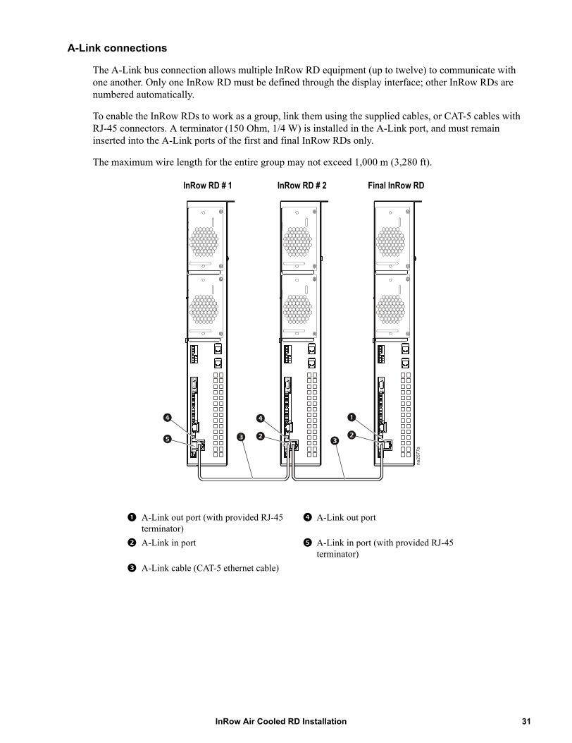
The A-Link bus connection allows multiple InRow RD equipment (up to twelve) to communicate with one another. Only one InRow RD must be defined through the display interface; other InRow RDs are numbered automatically.
To enable the InRow RDs to work as a group, link them using the supplied cables, or CAT-5 cables with RJ-45 connectors. A terminator (150 Ohm, 1/4 W) is installed in the A-Link port, and must remain inserted into the A-Link ports of the first and final InRow RDs only.
The maximum wire length for the entire group may not exceed 1,000 m (3,280 ft).
A-Link out port (with provided RJ-45 terminator)
A-Link out port
A-Link in port A-Link in port (with provided RJ-45 terminator)
A-Link cable (CAT-5 ethernet cable)
na26
77a
InRow RD # 1 InRow RD # 2 Final InRow RD
31InRow Air Cooled RD Installation
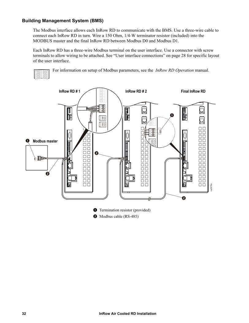
Building Management System (BMS)
The Modbus interface allows each InRow RD to communicate with the BMS. Use a three-wire cable to connect each InRow RD in turn. Wire a 150 Ohm, 1/4-W terminator resistor (included) into the MODBUS master and the final InRow RD between Modbus D0 and Modbus D1.
Each InRow RD has a three-wire Modbus terminal on the user interface. Use a connector with screw terminals to allow wiring to be attached. See “User interface connections” on page 28 for specific layout of the user interface.
For information on setup of Modbus parameters, see the InRow RD Operation manual.
Termination resistor (provided)
Modbus cable (RS-485)na
2678
a
InRow RD # 1 InRow RD # 2 Final InRow RD
Modbus master
InRow Air Cooled RD Installation32
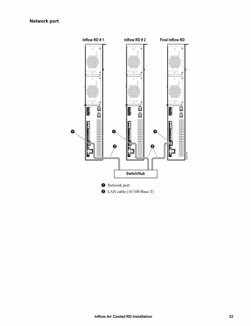
Network port
Network port
LAN cable (10/100 Base-T)na
2679
a
Switch/Hub
InRow RD # 1 InRow RD # 2 Final InRow RD
33InRow Air Cooled RD Installation

InRow Air Cooled RD Installation34
Power ConnectionsWiring configurations
Route incoming power to the electrical junction box located at the top or bottom of the equipment.
Electrical Hazard: Only a licensed electrician may connect the equipment to utility power.
Lock out and tag out all power sources before working with electrical wiring.
Do not wear jewelry when working near energized components.
Observe all local and national electrical codes.
Note: To ease installation and future removal of the equipment for repairs, use flexible conduit for the power wiring.
Top routing
1. Remove the electrical junction box cover.
2. Route electrical cabling into the electrical junction box as shown.
3. Secure the incoming cable with a standard 20 mm (3/4-in) nominal conduit strain relief (not provided).
4. Connect the power wiring to the terminals as shown and torque the screws to the value shown on the label.
5. Reinstall the electrical junction box cover.
Bottom routing
1. Carefully clip all the cable clamps that secure the electrical cable to the cabinet frame. Remove the cable clamps from the cabinet and discard.
2. Remove two screws securing the electrical junction box to the underside of the cabinet top.
3. Remove the plug from the cabinet floor and insert it in the cabinet top.
4. Turn the electrical junction box over and secure it to the bottom of the cabinet using the screws removed in step 1. See “Bottom piping and power access locations” on page 10.
5. Secure the electrical cable to the cabinet frame using new cable clamps (supplied).
6. To connect electrical power, follow the steps for top routing.
na26
45a
na26
46a
Connect flooded receiver heater
The flooded receiver is equipped with a heater to keep the refrigerant warm during extremely cold weather conditions. The heater requires 208 - 240/1~/60 Hz electrical service to be wired to the condenser electrical panel (see submittal drawings for details).
Warning: Make electrical connections in accordance with all local and national codes.
35InRow Air Cooled RD Installation
Warranty
One-Year Factory WarrantyThe limited warranty provided by American Power Conversion (APC®) in this Statement of Limited Factory Warranty applies only to products you purchase for your commercial or industrial use in the ordinary course of your business.
Terms of warranty
American Power Conversion warrants its products to be free from defects in materials and workmanship for a period of one year from the date of purchase. The obligation of APC under this warranty is limited to repairing or replacing, at its sole discretion, any such defective products. This warranty does not apply to equipment that has been damaged by accident, negligence or misapplication or has been altered or modified in any way. Repair or replacement of a defective product or part thereof does not extend the original warranty period. Any parts furnished under this warranty may be new or factory-remanufactured.
Non-transferable warranty
This warranty extends only to the original purchaser who must have properly registered the product. The product may be registered at the APC Web site, www.apc.com.
Exclusions
APC shall not be liable under the warranty if its testing and examination disclose that the alleged defect in the product does not exist or was caused by end user’s or any third person’s misuse, negligence, improper installation or testing. Further, APC shall not be liable under the warranty for unauthorized attempts to repair or modify wrong or inadequate electrical voltage or connection, inappropriate on-site operation conditions, corrosive atmosphere, repair, installation, start-up by non-APC designated personnel, a change in location or operating use, exposure to the elements, Acts of God, fire, theft, or installation contrary to APC recommendations or specifications or in any event if the APC serial number has been altered, defaced, or removed, or any other cause beyond the range of the intended use.
THERE ARE NO WARRANTIES, EXPRESS OR IMPLIED, BY OPERATION OF LAW OR OTHERWISE, OF PRODUCTS SOLD, SERVICED OR FURNISHED UNDER THIS AGREEMENT OR IN CONNECTION HEREWITH. APC DISCLAIMS ALL IMPLIED WARRANTIES OF MERCHANTABILITY, SATISFACTION AND FITNESS FOR A PARTICULAR PURPOSE. APC EXPRESS WARRANTIES WILL NOT BE ENLARGED, DIMINISHED, OR AFFECTED BY AND NO OBLIGATION OR LIABILITY WILL ARISE OUT OF, APC RENDERING OF TECHNICAL OR OTHER ADVICE OR SERVICE IN CONNECTION WITH THE PRODUCTS. THE FOREGOING WARRANTIES AND REMEDIES ARE EXCLUSIVE AND IN LIEU OF ALL OTHER WARRANTIES AND REMEDIES. THE WARRANTIES SET FORTH ABOVE CONSTITUTE APC’S SOLE LIABILITY AND PURCHASER’S EXCLUSIVE REMEDY FOR ANY BREACH OF SUCH WARRANTIES. APC WARRANTIES EXTEND ONLY TO PURCHASER AND ARE NOT EXTENDED TO ANY THIRD PARTIES.
InRow Air Cooled RD Installation36
IN NO EVENT SHALL APC, ITS OFFICERS, DIRECTORS, AFFILIATES OR EMPLOYEES BE LIABLE FOR ANY FORM OF INDIRECT, SPECIAL, CONSEQUENTIAL OR PUNITIVE DAMAGES, ARISING OUT OF THE USE, SERVICE OR INSTALLATION, OF THE PRODUCTS, WHETHER SUCH DAMAGES ARISE IN CONTRACT OR TORT, IRRESPECTIVE OF FAULT, NEGLIGENCE OR STRICT LIABILITY OR WHETHER APC HAS BEEN ADVISED IN ADVANCE OF THE POSSIBILITY OF SUCH DAMAGES. SPECIFICALLY, APC IS NOT LIABLE FOR ANY COSTS, SUCH AS LOST PROFITS OR REVENUE, LOSS OF EQUIPMENT, LOSS OF USE OF EQUIPMENT, LOSS OF SOFTWARE, LOSS OF DATA, COSTS OF SUBSTITUENTS, CLAIMS BY THIRD PARTIES, OR OTHERWISE.
NO SALESMAN, EMPLOYEE OR AGENT OF APC IS AUTHORIZED TO ADD TO OR VARY THE TERMS OF THIS WARRANTY. WARRANTY TERMS MAY BE MODIFIED, IF AT ALL, ONLY IN WRITING SIGNED BY AN APC OFFICER AND LEGAL DEPARTMENT.
Warranty claims
Customers with warranty claims issues may access the APC customer support network through the Support page of the APC Web site, www.apc.com/support. Select your country from the country selection pull-down menu at the top of the Web page. Select the Support tab to obtain contact information for customer support in your region.
37InRow Air Cooled RD Installation
Warranty Procedures
Claims
To obtain service under the warranty, contact APC Customer Support (see the back cover of this manual for contact information). You will need the model number of the Product, the serial number, and the date purchased. A technician will also ask you to describe the problem. If it is determined that the Product will need to be returned to APC, you must obtain a returned material authorization (RMA) number from APC Customer Support. Products that must be returned must have the RMA number marked on the outside of the package and must be returned with transportation charges prepaid. If it is determined by APC Customer Support that on-site repair of the Product is allowed, APC will arrange to have APC authorized service personnel dispatched to the Product location for repair or replacement, at the discretion of APC.
Parts
• APC warrants the parts of their systems for 1 year from the date of commissioning or 18 months from the ship date. This warranty only covers the cost of the part and not the labor for installation.
• Calls for warranty parts requests need to have specific unit information (serial number, model number, job number) to allow proper identification and processing of the warranty part transaction.
• A purchase order may be required to issue any warranty parts. An invoice will be sent once the parts are shipped to the field. You have 30 days to return the defective parts to APC. After 30 days, the warranty invoice will be outstanding, and payment of the invoice will be expected in full.
• Return authorization documentation will be sent with the replacement part. This documentation must be sent back with the defective part to APC for proper identification of the warranty return. Mark the warranty return number on the outside of the package.
• After the part has been received at APC, we will determine the status of the credit based on the findings of the returned part. Parts that are damaged from lack of maintenance, misapplication, improper installation, shipping damage, or acts of man/nature will not be covered under the parts warranty.
• Any warranty parts request received before 1:00 PM EST will be shipped same-day standard ground delivery. Any costs associated with Next Day or Airfreight will be the responsibility of the party requesting the part.
• Return freight of warranty parts to APC is the responsibility of the party returning the part.
InRow Air Cooled RD Installation38

Radio Frequency Interference
Changes or modifications to this unit not expressly approved by the party responsible for compliance could void the user’s authority to operate this equipment.
USA—FCC
This equipment has been tested and found to comply with the limits for a Class A digital device, pursuant to part 15 of the FCC Rules. These limits are designed to provide reasonable protection against harmful interference when the equipment is operated in a commercial environment. This equipment generates, uses, and can radiate radio frequency energy and, if not installed and used in accordance with this user manual, may cause harmful interference to radio communications. Operation of this equipment in a residential area is likely to cause harmful interference. The user will bear sole responsibility for correcting such interference.
Canada—ICES
This Class A digital apparatus complies with Canadian ICES-003.
Cet appareil numérique de la classe A est conforme à la norme NMB-003 du Canada.
Japan—VCCI
This is a Class A product based on the standard of the Voluntary Control Council for Interference by Information Technology Equipment (VCCI). If this equipment is used in a domestic environment, radio disturbance may occur, in which case, the user may be required to take corrective actions.
この装置は、情報処理装置等電波障害自主規制協議会(VCCI)の基準
に基づくクラス A 情報技術装置です。この装置を家庭環境で使用すると、電波
妨害を引き起こすことがあります。この場合には、使用者が適切な対策を講ず
るように要求されることがあります。
Taiwan—BSMI警告使用者 :這是甲類的資訊產品 , 在居住的環境中使用時 ,可能會造成射頻干擾 , 在這種情況下 ,使用者會被要求採取某些適當的對策。

07/2009990-3211A-001
APC Worldwide Customer SupportCustomer support for this or any other APC product is available at no charge in any of the following ways:
• Visit the APC Web site to access documents in the APC Knowledge Base and to submit customer support requests.– www.apc.com (Corporate Headquarters)
Connect to localized APC Web sites for specific countries, each of which provides customer support information.
– www.apc.com/support/Global support searching APC Knowledge Base and using e-support.
• Contact the APC Customer Support Center by telephone or e-mail.– Local, country-specific centers: go to www.apc.com/support/contact for contact information.
For information on how to obtain local customer support, contact the APC representative or other distributors from whom you purchased your APC product.
Entire contents copyright 2009 American Power Conversion Corporation. All rights reserved. Reproduction in whole or in part without permission is prohibited. APC, the APC logo, and InRow are trademarks of
American Power Conversion Corporation. All other trademarks, product names, and corporate names are the property of their respective owners and are used for informational purposes only.