(Inglese) MANUEL DE L’UTILISATEUR Marlin 100 EFI Narwhal ... MANUALS/Marlin 100 EFI... · OWNER'S...
64
Marlin 100 EFI OWNER'S MANUAL Narwhal 115 EFI (Inglese)
Transcript of (Inglese) MANUEL DE L’UTILISATEUR Marlin 100 EFI Narwhal ... MANUALS/Marlin 100 EFI... · OWNER'S...
MANUEL DE L’UTILISATEUR
Marlin 100 EFI
OWNER'S MANUAL
Narwhal 115 EFI
(Inglese)

Read this owner’s manual carefully before operating your outboard motor.
U6D770E0.book Page 1 Tuesday, October 12, 2004 5:00 PM
Important manual informationEMU25100
To the ownerThank you for choosing a Selva outboardmotor. This Owner’s Manual contains infor-mation needed for proper operation, mainte-nance and care. A thorough understanding ofthese simple instructions will help you obtainmaximum enjoyment from your new Selva.If you have any question about the operationor maintenance of your outboard motor,please consult a Selva dealer.In this Owner’s Manual particularly importantinformation is distinguished in the followingways.
The Safety Alert Symbol means AT-TENTION! BECOME ALERT! YOUR SAFE-TY IS INVOLVED!
WARNINGEWM00780
Failure to follow WARNING instructionscould result in severe injury or death to themachine operator, a bystander, or a per-son inspecting or repairing the outboardmotor.
CAUTION:ECM00700
A CAUTION indicates special precautionsthat must be taken to avoid damage to theoutboard motor.
NOTE:A NOTE provides key information to makeprocedures easier or clearer.
Selva continually seeks advancements inproduct design and quality. Therefore, whilethis manual contains the most current productinformation available at the time of printing,there may be minor discrepancies between
your machine and this manual. If there is anyquestion concerning this manual, please con-sult your Selva dealer.
NOTE:The Marlin 100, Narwhal 115 and the standard ac-cessories are used as a base for the explana-tions and illustrations in this manual.Therefore some items may not apply to everymodel.
EMU25120
U6D770E0.book Page 1 Tuesday, October 12, 2004 5:00 PM

Table of contents
General information ......................1Identification numbers record...... 1
Outboard motor serial number ....... 1Key number .................................... 1
EC label....................................... 1Safety information ....................... 2Important labels........................... 3
Warning labels................................ 3Fueling instructions ..................... 3
Gasoline ......................................... 3Engine oil........................................ 3
Battery requirement..................... 4Battery specifications ..................... 4
Propeller selection....................... 4Start-in-gear protection ............... 5
Basic components ........................6Main components........................ 6
Fuel tank......................................... 6Fuel joint......................................... 7Fuel gauge ..................................... 7Fuel tank cap.................................. 7Air vent screw................................. 7Remote control ............................... 7Remote control lever ...................... 7Neutral interlock trigger .................. 8Neutral throttle lever ....................... 8Throttle friction adjuster.................. 8Engine stop lanyard switch............. 8Main switch..................................... 9Power trim and tilt switch on
remote control or tiller handle ..... 9Power trim and tilt switch on
bottom engine cowling .............. 10Trim tab with anode...................... 10Tilt support lever for power trim
and tilt or hydro tilt model.......... 11Top cowling lock lever
(pull up type) ............................. 11Flushing device ............................ 11Digital tachometer ........................ 12Low oil pressure warning
indicator .................................... 12
Overheat warning indicator (digital type) .............................. 12
Speedometer (digital type) ........... 13Trim meter (digital type) ............... 13Hour meter (digital type) ............... 14Engine trouble warning
indicator .................................... 14Trip meter ..................................... 14Clock ............................................ 15Fuel gauge ................................... 15Fuel warning indicator .................. 15Low battery voltage warning
indicator .................................... 16Warning system ........................ 16
Overheat warning ......................... 16Low oil pressure warning.............. 17Engine trouble warning................. 17
Operation ..................................... 18Installation................................. 18
Mounting the outboard motor ....... 18Breaking in engine .................... 19
Procedure for 4-stroke models ..... 19Preoperation checks ................. 19
Fuel .............................................. 19Controls ........................................ 20Engine .......................................... 20Checking the engine oil level........ 20
Filling fuel.................................. 20Operating engine ...................... 21
Feeding fuel (portable tank) ......... 21Starting engine ............................. 22
Warming up engine................... 23Manual start and electric start
models ...................................... 23Shifting ...................................... 24
Forward (tiller handle and remote control models) ............. 24
Reverse (automatic reverse lock and power trim and tilt models) ........ 24
Stopping engine........................ 24Procedure..................................... 24
Trimming outboard motor.......... 25
U6D770E0.book Page 1 Tuesday, October 12, 2004 5:00 PM
Table of contents
Adjusting trim angle...................... 26Adjusting boat trim........................ 26
Tilting up and down ................... 27Procedure for tilting up ................. 28Procedure for tilting down............. 29
Cruising in shallow water .......... 29Power trim and tilt models /
power tilt models ....................... 29Cruising in other conditions....... 30
Maintenance.................................31Specifications ............................ 31Transporting and storing
outboard motor....................... 32Storing outboard motor................. 32Procedure..................................... 33Lubrication
(except oil injection models)...... 34Battery care .................................. 34Flushing power unit ...................... 35Cleaning the outboard motor........ 36Checking painted surface of
motor......................................... 36Periodic maintenance................ 36
Replacement parts ....................... 36Maintenance chart........................ 37Maintenance chart (additional) ..... 38Greasing....................................... 39Cleaning and adjusting spark
plug ........................................... 39Checking fuel system ................... 40Inspecting fuel filter ...................... 40Cleaning fuel filter......................... 41Inspecting idling speed................. 41Changing engine oil...................... 42Checking wiring and
connectors ................................ 44Exhaust leakage........................... 44Water leakage .............................. 44Engine oil leakage ........................ 44Checking power trim and tilt
system....................................... 44Checking propeller ....................... 45Removing the propeller ................ 46
Installing the Propeller .................. 46Changing gear oil ......................... 47Cleaning fuel tank......................... 48Inspecting and replacing
anode(s) .................................... 48Checking battery
(for electric start models) .......... 49Connecting the battery ................. 50Disconnecting the battery ............. 50Checking top cowling ................... 50Coating the boat bottom ............... 50
Trouble Recovery........................ 52Troubleshooting ........................ 52Temporary action in
emergency ............................. 55Impact damage............................. 55Replacing fuse.............................. 55Power trim and tilt will not
operate...................................... 56Starter will not operate ................. 56Emergency starting engine........... 57
Treatment of submerged motor...................................... 58Procedure..................................... 58
U6D770E0.book Page 2 Tuesday, October 12, 2004 5:00 PM

General information
1
EMU25170
Identification numbers recordEMU25182
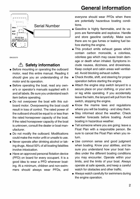
Outboard motor serial numberThe outboard motor serial number is stampedon the label attached to the port side of theclamp bracket or the upper part of the swivelbracket.Record your outboard motor serial number inthe spaces provided to assist you in orderingspare parts from your Selva dealer or forreference in case your outboard motor is sto-len.
EMU25190
Key numberIf a main key switch is equipped with the mo-tor, the key identification number is stampedon your key as shown in the illustration.Record this number in the space provided forreference in case you need a new key.
EMU25202
EC labelEngines affixed with this label conform to cer-tain portions of the European Parliament di-rective relating to machinery. Refer to thelabel and the EC Declaration of Conformity formore details.
1. Outboard motor serial number location
1
ZMU04214
1. Key number
U6D770E0.book Page 1 Tuesday, October 12, 2004 5:00 PM
1
1.EC label location
Giovanni
Linea
General information
2
EMU25370
Safety information� Before mounting or operating the outboard
motor, read this entire manual. Reading itshould give you an understanding of themotor and its operation.
� Before operating the boat, read any own-er’s or operator’s manuals supplied with itand all labels. Be sure you understand eachitem before operating.
� Do not overpower the boat with this out-board motor. Overpowering the boat couldresult in loss of control. The rated power ofthe outboard should be equal to or less thanthe rated horsepower capacity of the boat.If the rated horsepower capacity of the boatis unknown, consult the dealer or boat man-ufacturer.
� Do not modify the outboard. Modificationscould make the motor unfit or unsafe to use.
� Never operate after drinking alcohol or tak-ing drugs. About 50% of all boating fatalitiesinvolve intoxication.
� Have an approved personal flotation device(PFD) on board for every occupant. It is agood idea to wear a PFD whenever boat-ing. At a minimum, children and non-swim-mers should always wear PFDs, and
everyone should wear PFDs when thereare potentially hazardous boating condi-tions.
� Gasoline is highly flammable, and its va-pors are flammable and explosive. Handleand store gasoline carefully. Make surethere are no gas fumes or leaking fuel be-fore starting the engine.
� This product emits exhaust gases whichcontain carbon monoxide, a colorless,odorless gas which may cause brain dam-age or death when inhaled. Symptoms in-clude nausea, dizziness, and drowsiness.Keep cockpit and cabin areas well ventilat-ed. Avoid blocking exhaust outlets.
� Check throttle, shift, and steering for properoperation before starting the engine.
� Attach the engine stop switch lanyard to asecure place on your clothing, or your armor leg while operating. If you accidentallyleave the helm, the lanyard will pull from theswitch, stopping the engine.
� Know the marine laws and regulationswhere you will be boating - and obey them.
� Stay informed about the weather. Checkweather forecasts before boating. Avoidboating in hazardous weather.
� Tell someone where you are going: leave aFloat Plan with a responsible person. Besure to cancel the Float Plan when you re-turn.
� Use common sense and good judgmentwhen boating. Know your abilities, and besure you understand how your boat han-dles under the different boating conditionsyou may encounter. Operate within yourlimits, and the limits of your boat. Alwaysoperate at safe speeds, and keep a carefulwatch for obstacles and other traffic.
� Always watch carefully for swimmers duringthe engine operation.
U6D770E0.book Page 2 Tuesday, October 12, 2004 5:00 PM
Serial Number
General information
3
� Stay away from swimming areas.� When a swimmer is in the water near you
shift into neutral and shut off the engine.EMU25380
Important labelsEMU25395
Warning labels
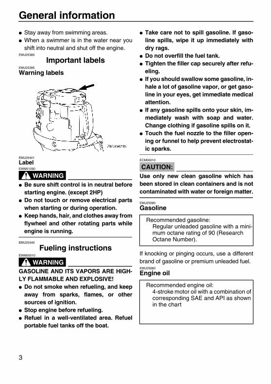
EMU25401
Label
WARNINGEWM01260
� Be sure shift control is in neutral beforestarting engine. (except 2HP)
� Do not touch or remove electrical partswhen starting or during operation.
� Keep hands, hair, and clothes away fromflywheel and other rotating parts whileengine is running.
EMU25540
Fueling instructions
WARNINGEWM00010
GASOLINE AND ITS VAPORS ARE HIGH-LY FLAMMABLE AND EXPLOSIVE!� Do not smoke when refueling, and keep
away from sparks, flames, or othersources of ignition.
� Stop engine before refueling.� Refuel in a well-ventilated area. Refuel
portable fuel tanks off the boat.
� Take care not to spill gasoline. If gaso-line spills, wipe it up immediately withdry rags.
� Do not overfill the fuel tank.� Tighten the filler cap securely after refu-
eling.� If you should swallow some gasoline, in-
hale a lot of gasoline vapor, or get gaso-line in your eyes, get immediate medicalattention.
� If any gasoline spills onto your skin, im-mediately wash with soap and water.Change clothing if gasoline spills on it.
� Touch the fuel nozzle to the filler open-ing or funnel to help prevent electrostat-ic sparks.
CAUTION:ECM00010
Use only new clean gasoline which hasbeen stored in clean containers and is notcontaminated with water or foreign matter.
EMU25580
Gasoline
If knocking or pinging occurs, use a differentbrand of gasoline or premium unleaded fuel.EMU25680
Engine oil
Recommended gasoline:Regular unleaded gasoline with a mini-mum octane rating of 90 (Research Octane Number).
Recommended engine oil:4-stroke motor oil with a combination of corresponding SAE and API as shown in the chart
U6D770E0.book Page 3 Tuesday, October 12, 2004 5:00 PM

General information
4
CAUTION:ECM01050
All 4-stroke engines are shipped from thefactory without engine oil.
EMU25700
Battery requirement
CAUTION:ECM01060
Do not use a battery that does not meet thespecified capacity. If a battery which doesnot meet specifications is used, the elec-tric system could perform poorly or beoverloaded, causing electric system dam-age.
For electric start models, choose a batterywhich meets the following specifications.
EMU25720
Battery specifications
NOTE:The engine cannot be started if battery volt-age is too low.
EMU25742
Propeller selectionThe performance of your outboard motor willbe critically affected by your choice of propel-ler, as an incorrect choice could adversely af-fect performance and could also seriouslydamage the motor. Engine speed depends onthe propeller size and boat load. If enginespeed is too high or too low for good engineperformance, this will have an adverse effecton the engine.Selva outboard motors are fitted with pro-pellers chosen to perform well over a range ofapplications, but there may be uses where apropeller with a different pitch would be moreappropriate. For a greater operating load, asmaller-pitch propeller is more suitable as itenables the correct engine speed to be main-tained. Conversely, a larger-pitch propeller ismore suitable for a smaller operating load.Selva dealers stock a range of propellers,and can advise you and install a propeller onyour outboard that is best suited to your appli-cation.
ZMU01710
Minimum cold cranking amps (CCA/EN):430.0 A
Minimum rated capacity (20HR/IEC):70.0 Ah
U6D770E0.book Page 4 Tuesday, October 12, 2004 5:00 PM

General information
5
NOTE:Select a propeller which will allow the engineto reach the middle or upper half of the oper-ating range at full throttle with the maximumboat load. If operating conditions such as lightboat loads then allow the engine r/min to riseabove the maximum recommended range, re-duce the throttle setting to maintain the en-gine in the proper operating range.
For instructions on propeller removal and in-stallation, see page 45.
EMU25760
Start-in-gear protectionSelva outboard motors affixed with the pic-tured label or Selva-approved remote con-trol units are equipped with start-in-gearprotection device(s). This feature permits theengine to be started only when it is in neutral.Always select neutral before starting the en-gine.
1. Propeller diameter in inches2. Propeller pitch in inches3. Type of propeller (propeller mark)
1. Propeller diameter in inches2. Propeller pitch in inches3. Type of propeller (propeller mark)
ZMU04606
-x1 2 3
ZMU04607
-x1 2 3 1. Start-in-gear protection label
ZMU01713
1
U6D770E0.book Page 5 Tuesday, October 12, 2004 5:00 PM

Basic components
6
EMU25795
Main components
NOTE:* May not be exactly as shown; also may not be included as standard equipment on all models.
EMU25802
Fuel tankIf your model was equipped with a portablefuel tank, its function is as follows.
WARNINGEWM00020
The fuel tank supplied with this engine isits dedicated fuel reservoir and must notbe used as a fuel storage container. Com-mercial users should conform to relevantlicensing or approval authority regula-tions.
1. Top cowling2. Top cowling lock lever(s)3. Anti-cavitation plate4. Trim tab (anode)5. Propeller*6. Cooling water inlet7. Clamp bracket8. Flushing device9. Power trim and tilt switch10.Remote control box (side mount type)*11.Digital speedometer*12.Digital tachometer*13.Fuel tank*
U6D770E0.book Page 6 Tuesday, October 12, 2004 5:00 PM
Basic components
7
EMU25850
Fuel tank capThis cap seals the fuel tank. When removed,the tank can be filled with fuel. To remove thecap, turn it counterclockwise.EMU25860
Air vent screwThis screw is on the fuel tank cap. To loosenthe screw, turn it counterclockwise.EMU26180
Remote controlThe remote control lever actuates both theshifter and the throttle. The electrical switchesare mounted on the remote control box.
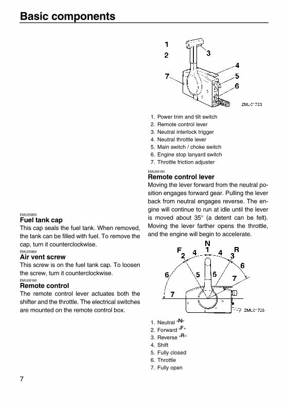
EMU26190
Remote control leverMoving the lever forward from the neutral po-sition engages forward gear. Pulling the leverback from neutral engages reverse. The en-gine will continue to run at idle until the leveris moved about 35° (a detent can be felt).Moving the lever farther opens the throttle,and the engine will begin to accelerate.
1. Power trim and tilt switch2. Remote control lever3. Neutral interlock trigger4. Neutral throttle lever5. Main switch / choke switch6. Engine stop lanyard switch7. Throttle friction adjuster
1. Neutral “ ”2. Forward “ ”3. Reverse “ ”4. Shift5. Fully closed6. Throttle7. Fully open
U6D770E0.book Page 7 Tuesday, October 12, 2004 5:00 PM

Basic components
8
EMU26201
Neutral interlock triggerTo shift out of neutral, first pull the neutral in-terlock trigger up.
EMU26211
Neutral throttle leverTo open the throttle without shifting into eitherforward or reverse, put the remote control le-ver in the neutral position and lift the neutralthrottle lever.
NOTE:The neutral throttle lever will operate onlywhen the remote control lever is in neutral.The remote control lever will operate onlywhen the neutral throttle lever is in the closedposition.
EMU25970
Throttle friction adjusterA friction device provides adjustable resis-tance to movement of the throttle grip or theremote control lever, and can be set accord-ing to operator preference.To increase resistance, turn the adjusterclockwise. To decrease resistance, turn theadjuster counterclockwise.
WARNINGEWM00030
Do not overtighten the friction adjuster. Ifthere is too much resistance, it could bedifficult to move throttle lever or grip,which could result in an accident.
When constant speed is desired, tighten theadjuster to maintain the desired throttle set-ting.EMU25990
Engine stop lanyard switchThe lock plate must be attached to the enginestop switch for the engine to run. The lanyardshould be attached to a secure place on theoperator’s clothing, or arm or leg. Should theoperator fall overboard or leave the helm, thelanyard will pull out the lock plate, stopping ig-nition to the engine. This will prevent the boatfrom running away under power.
1. Neutral interlock trigger
1. Fully open2. Fully closed
U6D770E0.book Page 8 Tuesday, October 12, 2004 5:00 PM

Basic components
9
WARNINGEWM00120
� Attach the engine stop switch lanyard toa secure place on your clothing, or yourarm or leg while operating.
� Do not attach the lanyard to clothingthat could tear loose. Do not route thelanyard where it could become entan-gled, preventing it from functioning.
� Avoid accidentally pulling the lanyardduring normal operation. Loss of enginepower means the loss of most steeringcontrol. Also, without engine power, theboat could slow rapidly. This couldcause people and objects in the boat tobe thrown forward.
NOTE:The engine cannot be started with the lockplate removed.
EMU26090
Main switchThe main switch controls the ignition system;its operation is described below.� “ ” (off)With the main switch in the “ ” (off) posi-tion, the electrical circuits are off, and the keycan be removed.� “ ” (on)
With the main switch in the “ ” (on) position,the electrical circuits are on, and the key can-not be removed.� “ ” (start)With the main switch in the “ ” (start) po-sition, the starter motor turns to start the en-gine. When the key is released, it returnsautomatically to the “ ” (on) position.
EMU26141
Power trim and tilt switch on remote control or tiller handleThe power trim and tilt system adjusts the out-board motor angle in relation to the transom.Pressing the switch “ ” (up) trims the out-board motor up, then tilts it up. Pressing theswitch “ ” (down) tilts the outboard motordown and trims it down. When the switch is re-leased, the outboard motor will stop in its cur-rent position.
NOTE:For instructions on using the power trim andtilt switch, see pages 25 and 27.
1. Lanyard2. Lock plate
U6D770E0.book Page 9 Tuesday, October 12, 2004 5:00 PM
Basic components
10
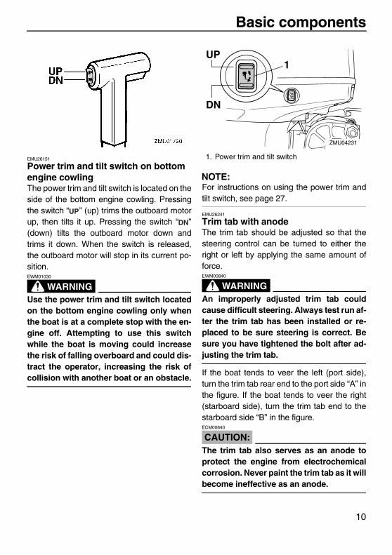
EMU26151
Power trim and tilt switch on bottom engine cowlingThe power trim and tilt switch is located on theside of the bottom engine cowling. Pressingthe switch “ ” (up) trims the outboard motorup, then tilts it up. Pressing the switch “ ”(down) tilts the outboard motor down andtrims it down. When the switch is released,the outboard motor will stop in its current po-sition.
WARNINGEWM01030
Use the power trim and tilt switch locatedon the bottom engine cowling only whenthe boat is at a complete stop with the en-gine off. Attempting to use this switchwhile the boat is moving could increasethe risk of falling overboard and could dis-tract the operator, increasing the risk ofcollision with another boat or an obstacle.
NOTE:For instructions on using the power trim andtilt switch, see page 27.
EMU26241
Trim tab with anodeThe trim tab should be adjusted so that thesteering control can be turned to either theright or left by applying the same amount offorce.
WARNINGEWM00840
An improperly adjusted trim tab couldcause difficult steering. Always test run af-ter the trim tab has been installed or re-placed to be sure steering is correct. Besure you have tightened the bolt after ad-justing the trim tab.
If the boat tends to veer the left (port side),turn the trim tab rear end to the port side “A” inthe figure. If the boat tends to veer the right(starboard side), turn the trim tab end to thestarboard side “B” in the figure.
CAUTION:ECM00840
The trim tab also serves as an anode toprotect the engine from electrochemicalcorrosion. Never paint the trim tab as it willbecome ineffective as an anode.
1. Power trim and tilt switch
UP
DN
1
ZMU04231
U6D770E0.book Page 10 Tuesday, October 12, 2004 5:00 PM
Basic components
11
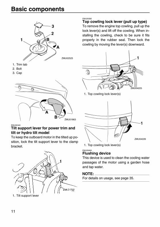
EMU26340
Tilt support lever for power trim and tilt or hydro tilt modelTo keep the outboard motor in the tilted up po-sition, lock the tilt support lever to the clampbracket.
EMU26382
Top cowling lock lever (pull up type)To remove the engine top cowling, pull up thelock lever(s) and lift off the cowling. When in-stalling the cowling, check to be sure it fitsproperly in the rubber seal. Then lock thecowling by moving the lever(s) downward.
EMU26460
Flushing deviceThis device is used to clean the cooling waterpassages of the motor using a garden hoseand tap water.
NOTE:For details on usage, see page 35.
1. Trim tab2. Bolt3. Cap
1. Tilt support lever
1
2
3
ZMU02525
A
B
AB
ZMU01863
1. Top cowling lock lever(s)
1. Top cowling lock lever(s)
ZMU04225
1
ZMU04226
1
U6D770E0.book Page 11 Tuesday, October 12, 2004 5:00 PM
Basic components
12
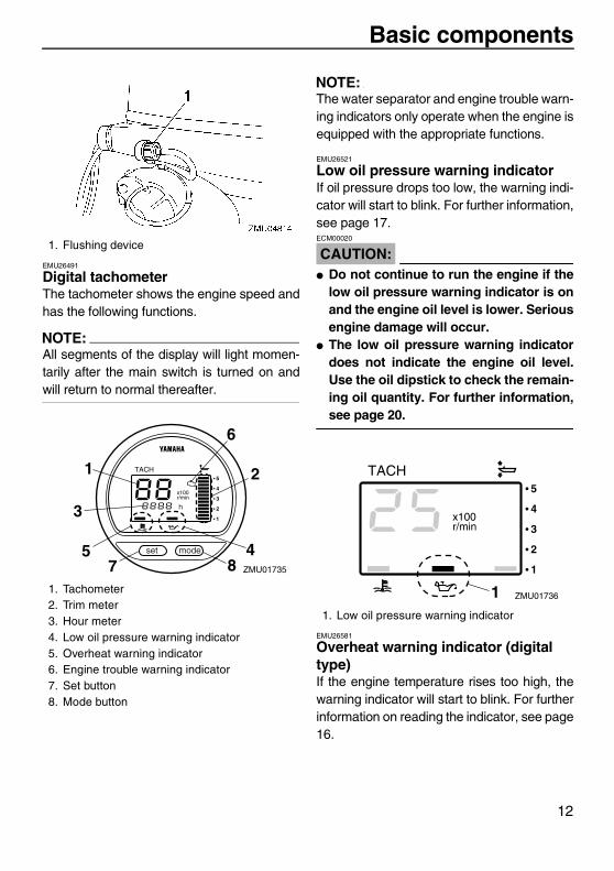
EMU26491
Digital tachometerThe tachometer shows the engine speed andhas the following functions.
NOTE:All segments of the display will light momen-tarily after the main switch is turned on andwill return to normal thereafter.
NOTE:The water separator and engine trouble warn-ing indicators only operate when the engine isequipped with the appropriate functions.
EMU26521
Low oil pressure warning indicatorIf oil pressure drops too low, the warning indi-cator will start to blink. For further information,see page 17.
CAUTION:ECM00020
� Do not continue to run the engine if thelow oil pressure warning indicator is onand the engine oil level is lower. Seriousengine damage will occur.
� The low oil pressure warning indicatordoes not indicate the engine oil level.Use the oil dipstick to check the remain-ing oil quantity. For further information,see page 20.
EMU26581
Overheat warning indicator (digital type)If the engine temperature rises too high, thewarning indicator will start to blink. For furtherinformation on reading the indicator, see page16.
1. Flushing device
1. Tachometer2. Trim meter3. Hour meter4. Low oil pressure warning indicator5. Overheat warning indicator6. Engine trouble warning indicator7. Set button8. Mode button
ZMU01735
1
5
2
4
3
6
7 8
1. Low oil pressure warning indicator
ZMU017361
U6D770E0.book Page 12 Tuesday, October 12, 2004 5:00 PM
Basic components
13
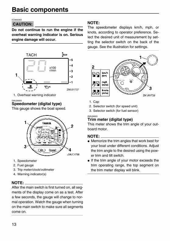
CAUTION:ECM00050
Do not continue to run the engine if theoverheat warning indicator is on. Seriousengine damage will occur.
EMU26600
Speedometer (digital type)This gauge shows the boat speed.
NOTE:After the main switch is first turned on, all seg-ments of the display come on as a test. Aftera few seconds, the gauge will change to nor-mal operation. Watch the gauge when turningon the main switch to make sure all segmentscome on.
NOTE:The speedometer displays km/h, mph, orknots, according to operator preference. Se-lect the desired unit of measurement by set-ting the selector switch on the back of thegauge. See the illustration for settings.
EMU26620
Trim meter (digital type)This meter shows the trim angle of your out-board motor.
NOTE:� Memorize the trim angles that work best for
your boat under different conditions. Adjustthe trim angle to the desired using the pow-er trim and tilt switch.
� If the trim angle of your motor exceeds thetrim operating range, the top segment onthe trim meter display will blink.
1. Overheat warning indicator
1. Speedometer2. Fuel gauge3. Trip meter/clock/voltmeter4. Warning indicator(s)
ZMU01737
1
1. Cap2. Selector switch (for speed unit)3. Selector switch (for fuel sensor)
U6D770E0.book Page 13 Tuesday, October 12, 2004 5:00 PM

Basic components
14
EMU26650
Hour meter (digital type)This meter shows the number of hours the en-gine has been run. It can be set to show thetotal number of hours or the number of hoursfor the current trip. The display can also beturned on and off.
� Changing the display formatPressing the “ ” (mode) button chang-es the display format in the following pat-tern:Total hours→Trip hours→Display off
� Resetting the trip hoursSimultaneously pressing the “ ” (set) and“ ” (mode) buttons for more than 1 sec-ond while the trip hours are displayed re-sets the trip counter to 0 (zero).
NOTE:The total number of hours the engine hasbeen run cannot be reset.
EMU26680
Engine trouble warning indicatorThis indicator will blink when the engine mal-functions.
CAUTION:ECM00920
In such an event, the engine will not oper-ate properly. Consult a Selva-dealer im-mediately.
EMU26690
Trip meterThis gauge displays the distance the boat hastraveled since the gauge was last reset.Press the “ ” (mode) button repeatedlyuntil the indicator on the face of the gaugepoints to “ ” (trip). To reset the trip meter tozero, press the “ ” (set) and “ ” (mode)buttons at the same time.
ZMU01740
ZMU01741
1. Engine trouble warning indicator
ZMU01742
1
U6D770E0.book Page 14 Tuesday, October 12, 2004 5:00 PM
Basic components
15
NOTE:� The trip distance is shown in kilometers or
miles depending upon the unit of measure-ment selected for the speedometer.
� The trip distance is kept in memory by bat-tery power. The stored data will be lost if thebattery is disconnected.
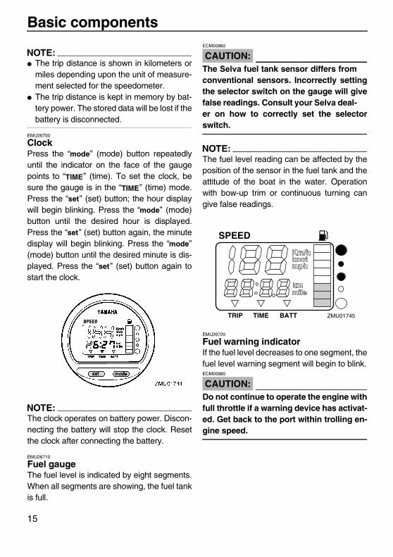
EMU26700
ClockPress the “ ” (mode) button repeatedlyuntil the indicator on the face of the gaugepoints to “ ” (time). To set the clock, besure the gauge is in the “ ” (time) mode.Press the “ ” (set) button; the hour displaywill begin blinking. Press the “ ” (mode)button until the desired hour is displayed.Press the “ ” (set) button again, the minutedisplay will begin blinking. Press the “ ”(mode) button until the desired minute is dis-played. Press the “ ” (set) button again tostart the clock.
NOTE:The clock operates on battery power. Discon-necting the battery will stop the clock. Resetthe clock after connecting the battery.
EMU26710
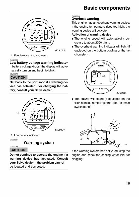
Fuel gaugeThe fuel level is indicated by eight segments.When all segments are showing, the fuel tankis full.
CAUTION:ECM00860
The Selva fuel tank sensor differs fromconventional sensors. Incorrectly settingthe selector switch on the gauge will givefalse readings. Consult your Selva deal-er on how to correctly set the selectorswitch.
NOTE:The fuel level reading can be affected by theposition of the sensor in the fuel tank and theattitude of the boat in the water. Operationwith bow-up trim or continuous turning cangive false readings.
EMU26720
Fuel warning indicatorIf the fuel level decreases to one segment, thefuel level warning segment will begin to blink.
CAUTION:ECM00880
Do not continue to operate the engine withfull throttle if a warning device has activat-ed. Get back to the port within trolling en-gine speed.
ZMU01745
U6D770E0.book Page 15 Tuesday, October 12, 2004 5:00 PM
Basic components
16
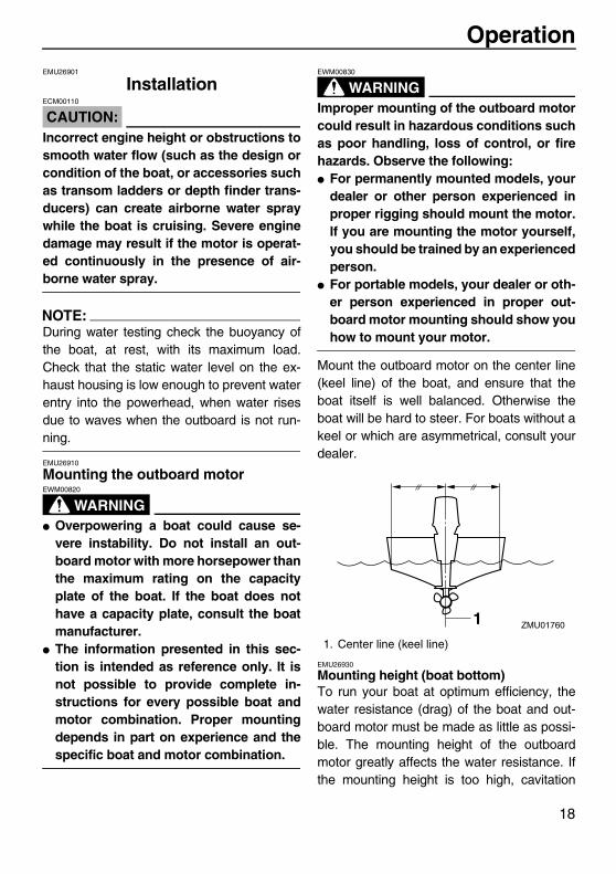
EMU26730
Low battery voltage warning indicatorIf battery voltage drops, the display will auto-matically turn on and begin to blink.
CAUTION:ECM00870
Get back to the port soon if a warning de-vice has activated. For charging the bat-tery, consult your Selva dealer.
EMU26801
Warning system
CAUTION:ECM00090
Do not continue to operate the engine if awarning device has activated. Consultyour Selva dealer if the problem cannotbe located and corrected.
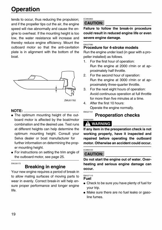
EMU26813
Overheat warningThis engine has an overheat warning device.If the engine temperature rises too high, thewarning device will activate.Activation of warning device� The engine speed will automatically de-
crease to about 2000 r/min.� The overheat warning indicator will light (if
equipped on the bottom cowling or the ta-chometer).
� The buzzer will sound (if equipped on thetiller handle, remote control box, or mainswitch panel).
If the warning system has activated, stop theengine and check the cooling water inlet forclogging.
1. Fuel level warning segment
1. Low battery indicator
ZMU01757
U6D770E0.book Page 16 Tuesday, October 12, 2004 5:00 PM

Basic components
17
EMU26854
Low oil pressure warningIf the oil pressure drops too low, the warningdevice will activate.Activation of warning device� The engine speed will automatically de-
crease to about 2000 r/min.� The low oil pressure warning indicator will
light.
� The buzzer will sound.
If the warning system has activated, stop theengine as soon as it is safe to do so. Checkthe oil level and add oil as needed. If the oillevel is correct and the warning device doesnot switch off, consult your Selva dealer.
CAUTION:ECM00100
Do not continue to run the engine if thelow oil pressure warning indicator is on.Serious engine damage could occur.
EMU26880
Engine trouble warningWhen an engine malfunction is detected, theengine trouble warning indicator will blink. Insuch an event, the engine will not operateproperly. Consult a Selva dealer immedi-ately.
ZMU02630
ZMU018281. Engine trouble warning indicator
ZMU01759
1
U6D770E0.book Page 17 Tuesday, October 12, 2004 5:00 PM
Operation
18
EMU26901
Installation
CAUTION:ECM00110
Incorrect engine height or obstructions tosmooth water flow (such as the design orcondition of the boat, or accessories suchas transom ladders or depth finder trans-ducers) can create airborne water spraywhile the boat is cruising. Severe enginedamage may result if the motor is operat-ed continuously in the presence of air-borne water spray.
NOTE:During water testing check the buoyancy ofthe boat, at rest, with its maximum load.Check that the static water level on the ex-haust housing is low enough to prevent waterentry into the powerhead, when water risesdue to waves when the outboard is not run-ning.
EMU26910
Mounting the outboard motor
WARNINGEWM00820
� Overpowering a boat could cause se-vere instability. Do not install an out-board motor with more horsepower thanthe maximum rating on the capacityplate of the boat. If the boat does nothave a capacity plate, consult the boatmanufacturer.
� The information presented in this sec-tion is intended as reference only. It isnot possible to provide complete in-structions for every possible boat andmotor combination. Proper mountingdepends in part on experience and thespecific boat and motor combination.
WARNINGEWM00830
Improper mounting of the outboard motorcould result in hazardous conditions suchas poor handling, loss of control, or firehazards. Observe the following:� For permanently mounted models, your
dealer or other person experienced inproper rigging should mount the motor.If you are mounting the motor yourself,you should be trained by an experiencedperson.
� For portable models, your dealer or oth-er person experienced in proper out-board motor mounting should show youhow to mount your motor.
Mount the outboard motor on the center line(keel line) of the boat, and ensure that theboat itself is well balanced. Otherwise theboat will be hard to steer. For boats without akeel or which are asymmetrical, consult yourdealer.
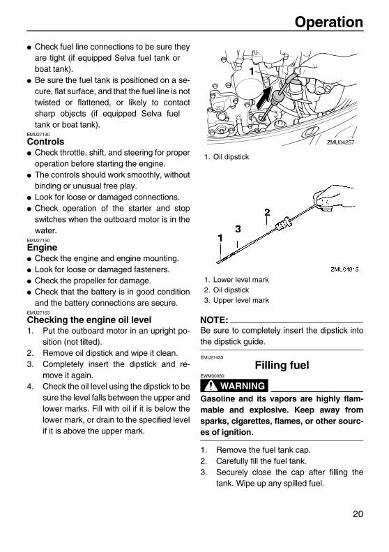
EMU26930
Mounting height (boat bottom)To run your boat at optimum efficiency, thewater resistance (drag) of the boat and out-board motor must be made as little as possi-ble. The mounting height of the outboardmotor greatly affects the water resistance. Ifthe mounting height is too high, cavitation
1. Center line (keel line)
ZMU017601
U6D770E0.book Page 18 Tuesday, October 12, 2004 5:00 PM
Operation
19
tends to occur, thus reducing the propulsion;and if the propeller tips cut the air, the enginespeed will rise abnormally and cause the en-gine to overheat. If the mounting height is toolow, the water resistance will increase andthereby reduce engine efficiency. Mount theoutboard motor so that the anti-cavitationplate is in alignment with the bottom of theboat.
NOTE:� The optimum mounting height of the out-
board motor is affected by the boat/motorcombination and the desired use. Test runsat different heights can help determine theoptimum mounting height. Consult yourSelva dealer or boat manufacturer forfurther information on determining the prop-er mounting height.
� For instructions on setting the trim angle ofthe outboard motor, see page 25.
EMU30172
Breaking in engineYour new engine requires a period of break-into allow mating surfaces of moving parts towear in evenly. Correct break-in will help en-sure proper performance and longer enginelife.
CAUTION:ECM00800
Failure to follow the break-in procedurecould result in reduced engine life or evensevere engine damage.
EMU27080
Procedure for 4-stroke modelsRun the engine under load (in gear with a pro-peller installed) as follows.1. For the first hour of operation:
Run the engine at 2000 r/min or at ap-proximately half throttle.
2. For the second hour of operation:Run the engine at 3000 r/min or at ap-proximately three-quarter throttle.
3. For the next eight hours of operation:Avoid continuous operation at full throttlefor more than five minutes at a time.
4. After the first 10 hours:Operate the engine normally.
EMU27101
Preoperation checks
WARNINGEWM00080
If any item in the preoperation check is notworking properly, have it inspected andrepaired before operating the outboardmotor. Otherwise an accident could occur.
CAUTION:ECM00120
Do not start the engine out of water. Over-heating and serious engine damage canoccur.
EMU27110
Fuel� Check to be sure you have plenty of fuel for
your trip.� Make sure there are no fuel leaks or gaso-
line fumes.
ZMU01762
U6D770E0.book Page 19 Tuesday, October 12, 2004 5:00 PM
Operation
20
� Check fuel line connections to be sure theyare tight (if equipped Selva fuel tank orboat tank).
� Be sure the fuel tank is positioned on a se-cure, flat surface, and that the fuel line is nottwisted or flattened, or likely to contactsharp objects (if equipped Selva fueltank or boat tank).
EMU27130
Controls� Check throttle, shift, and steering for proper
operation before starting the engine.� The controls should work smoothly, without
binding or unusual free play.� Look for loose or damaged connections.� Check operation of the starter and stop
switches when the outboard motor is in thewater.
EMU27150
Engine� Check the engine and engine mounting.� Look for loose or damaged fasteners.� Check the propeller for damage.� Check that the battery is in good condition
and the battery connections are secure.EMU27163
Checking the engine oil level1. Put the outboard motor in an upright po-
sition (not tilted).2. Remove oil dipstick and wipe it clean.3. Completely insert the dipstick and re-
move it again.4. Check the oil level using the dipstick to be
sure the level falls between the upper andlower marks. Fill with oil if it is below thelower mark, or drain to the specified levelif it is above the upper mark.
NOTE:Be sure to completely insert the dipstick intothe dipstick guide.
EMU27433
Filling fuel
WARNINGEWM00060
Gasoline and its vapors are highly flam-mable and explosive. Keep away fromsparks, cigarettes, flames, or other sourc-es of ignition.
1. Remove the fuel tank cap.2. Carefully fill the fuel tank.3. Securely close the cap after filling the
tank. Wipe up any spilled fuel.
1. Oil dipstick
1. Lower level mark2. Oil dipstick3. Upper level mark
ZMU04257
1
U6D770E0.book Page 20 Tuesday, October 12, 2004 5:00 PM

Operation
21
EMU27450
Operating engineEMU27461
Feeding fuel (portable tank)
WARNINGEWM00420
� Before starting the engine, make surethat the boat is tightly moored and thatyou can steer clear of any obstructions.Be sure there are no swimmers in thewater near you.
� When the air vent screw is loosened,gasoline vapor will be released. Gaso-line is highly flammable, and its vaporsare flammable and explosive. Refrainfrom smoking, and keep away fromopen flames and sparks while looseningthe air vent screw.
� This product emits exhaust gases whichcontain carbon monoxide, a colorless,odorless gas which could cause braindamage or death when inhaled. Symp-toms include nausea, dizziness, anddrowsiness. Keep cockpit and cabin ar-eas well ventilated. Avoid blocking ex-haust outlets.
1. If there is an air vent screw on the fueltank cap, loosen it 2 or 3 turns.
2. If there is a fuel joint on the motor, firmlyconnect the fuel line to the joint. Thenfirmly connect the other end of the fuelline to the joint on the fuel tank.
3. If a steering friction adjuster is providedon your outboard motor, securely attachthe fuel line to the fuel line clamp.
NOTE:During engine operation place the tank hori-zontally, otherwise fuel cannot be drawn fromthe fuel tank.
4. Squeeze the primer pump with the outletend up until you feel it become firm.
Fuel tank capacity:25.0 L (6.61 US gal) (5.50 Imp.gal)
ZMU04047
ZMU02022
U6D770E0.book Page 21 Tuesday, October 12, 2004 5:00 PM

Operation
22
EMU27490
Starting engineEMU27624
Electric start and remote control models1. Place the remote control lever in “ ”
(neutral).
NOTE:The start-in-gear protection device preventsthe engine from starting except when in neu-tral.
2. Attach the engine stop switch lanyard toa secure place on your clothing, or yourarm or leg. Then install the lock plate onthe other end of the lanyard into the en-gine stop switch.
WARNINGEWM00120
� Attach the engine stop switch lanyard toa secure place on your clothing, or yourarm or leg while operating.
� Do not attach the lanyard to clothingthat could tear loose. Do not route thelanyard where it could become entan-gled, preventing it from functioning.
� Avoid accidentally pulling the lanyardduring normal operation. Loss of enginepower means the loss of most steeringcontrol. Also, without engine power, theboat could slow rapidly. This couldcause people and objects in the boat tobe thrown forward.
3. Turn the main switch to “ ” (on).
NOTE:Dual engine users: When the main switch isturned on, the buzzer operates for a few sec-onds then stops automatically. The buzzeralso operates if one of the engines stalls.
4. Turn the main switch to “ ” (start),and hold it for a maximum of 5 seconds.
ZMU02025
U6D770E0.book Page 22 Tuesday, October 12, 2004 5:00 PM

Operation
23
5. Immediately after the engine starts, re-lease the main switch to return it to “ ”(on).
CAUTION:ECM00191
� Never turn the main switch to “ ”(start) while the engine is running.
� Do not keep the starter motor turning formore than 5 seconds. If the starter motoris turned continuously for more than 5seconds, the battery will be quickly dis-charged, thus making it impossible tostart the engine. The starter can also bedamaged. If the engine will not start after5 seconds of cranking, return the mainswitch to “ ” (on), wait 10 seconds,then crank the engine again.
EMU27670
Warming up engineEMU30030
Manual start and electric start models1. After starting the engine, allow it to idle for
3 minutes to warm up. Failure to do so willshorten engine life.
2. Be sure the low oil pressure warning indi-cator goes off after starting the engine.
3. Check for a steady flow of water from thecooling water pilot hole.
CAUTION:ECM01340
� If the low oil pressure warning indicatordoes not go off after the engine starts,stop the engine. Otherwise serious en-gine damage could occur. Check the oillevel and add oil if necessary. Consultyour Selva dealer if the cause for thelow oil pressure warning indicator can-not be found.
� A continuous flow of water from the pilothole shows that the water pump ispumping water through the cooling pas-sages. If water is not flowing out of thepilot hole at all times while the engine isrunning, overheating and serious dam-age could occur. Stop the engine andcheck whether the cooling water inlet onthe lower case or the cooling water pilothole is blocked. Consult your Selvadealer if the problem cannot be locatedand corrected.
� If the cooling passage is frozen, it maytake awhile for water to start flowing outof the pilot hole.
ON STARTOFF
ZMU01881
U6D770E0.book Page 23 Tuesday, October 12, 2004 5:00 PM

Operation
24
EMU27740
Shifting
WARNINGEWM00180
Before shifting, make sure there are noswimmers or obstacles in the water nearyou.
CAUTION:ECM00220
To change the boat direction or shiftingposition from forward to reverse or vice-versa, first close the throttle so that the en-gine idles (or runs at low speeds).
EMU27763
Forward (tiller handle and remote control models)Tiller control models1. Place the throttle grip in the fully closed
position.2. Move the gear shift lever quickly and firm-
ly from neutral to forward.Remote control modelsPull up the neutral interlock trigger (ifequipped) and move the remote control leverquickly and firmly from neutral to forward.
EMU27784
Reverse (automatic reverse lock and power trim and tilt models)
WARNINGEWM00190
When operating in reverse, go slowly. Donot open the throttle more than half. Other-wise the boat could become unstable,which could result in loss of control andan accident.
Tiller control models1. Place the throttle grip in the fully closed
position.2. Move the gear shift lever quickly and firm-
ly from neutral to reverse.Remote control modelsPull up the neutral interlock trigger (ifequipped) and move the remote control leverquickly and firmly from neutral to reverse.
EMU27820
Stopping engineBefore stopping the engine, first let it cool offfor a few minutes at idle or low speed. Stop-ping the engine immediately after operating athigh speed is not recommended.EMU27844
Procedure1. Push and hold the engine stop button or
turn the main switch to “ ” (off).
U6D770E0.book Page 24 Tuesday, October 12, 2004 5:00 PM
Operation
25
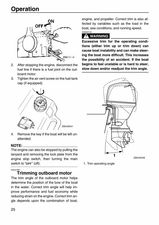
2. After stopping the engine, disconnect thefuel line if there is a fuel joint on the out-board motor.
3. Tighten the air vent screw on the fuel tankcap (if equipped).
4. Remove the key if the boat will be left un-attended.
NOTE:The engine can also be stopped by pulling thelanyard and removing the lock plate from theengine stop switch, then turning the mainswitch to “ ” (off).
EMU27861
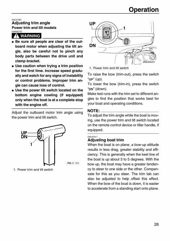
Trimming outboard motorThe trim angle of the outboard motor helpsdetermine the position of the bow of the boatin the water. Correct trim angle will help im-prove performance and fuel economy whilereducing strain on the engine. Correct trim an-gle depends upon the combination of boat,
engine, and propeller. Correct trim is also af-fected by variables such as the load in theboat, sea conditions, and running speed.
WARNINGEWM00740
Excessive trim for the operating condi-tions (either trim up or trim down) cancause boat instability and can make steer-ing the boat more difficult. This increasesthe possibility of an accident. If the boatbegins to feel unstable or is hard to steer,slow down and/or readjust the trim angle.
ZMU02041
1. Trim operating angle
1ZMU04258
U6D770E0.book Page 25 Tuesday, October 12, 2004 5:00 PM
Operation
26
EMU27881
Adjusting trim anglePower trim and tilt models
WARNINGEWM00750
� Be sure all people are clear of the out-board motor when adjusting the tilt an-gle, also be careful not to pinch anybody parts between the drive unit andclamp bracket.
� Use caution when trying a trim positionfor the first time. Increase speed gradu-ally and watch for any signs of instabilityor control problems. Improper trim an-gle can cause loss of control.
� Use the power tilt switch located on thebottom engine cowling (if equipped)only when the boat is at a complete stopwith the engine off.
Adjust the outboard motor trim angle usingthe power trim and tilt switch.
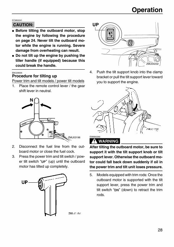
To raise the bow (trim-out), press the switch“ ” (up).To lower the bow (trim-in), press the switch“ ” (down).Make test runs with the trim set to different an-gles to find the position that works best foryour boat and operating conditions.
NOTE:To adjust the trim angle while the boat is mov-ing, use the power trim and tilt switch locatedon the remote control device or tiller handle, ifequipped.
EMU27911
Adjusting boat trimWhen the boat is on plane, a bow-up attituderesults in less drag, greater stability and effi-ciency. This is generally when the keel line ofthe boat is up about 3 to 5 degrees. With thebow up, the boat may have a greater tenden-cy to steer to one side or the other. Compen-sate for this as you steer. The trim tab canalso be adjusted to help offset this effect.When the bow of the boat is down, it is easierto accelerate from a standing start onto plane.
1. Power trim and tilt switch
1. Power trim and tilt switch
UP
DN
1
ZMU04231
U6D770E0.book Page 26 Tuesday, October 12, 2004 5:00 PM

Operation
27
Bow UpToo much trim-out puts the bow of the boattoo high in the water. Performance and econ-omy are decreased because the hull of theboat is pushing the water and there is more airdrag. Excessive trim-out can also cause thepropeller to ventilate, which reduces perfor-mance further, and the boat may “porpoise”(hop in the water), which could throw the op-erator and passengers overboard.
Bow DownToo much trim-in causes the boat to “plow”through the water, decreasing fuel economyand making it hard to increase speed. Operat-ing with excessive trim-in at higher speedsalso makes the boat unstable. Resistance atthe bow is greatly increased, heightening thedanger of “bow steering” and making opera-tion difficult and dangerous.
NOTE:Depending on the type of boat, the outboardmotor trim angle may have little effect on thetrim of the boat when operating.
EMU27933
Tilting up and downIf the engine will be stopped for some time orif the boat is moored in shallows, the outboardmotor should be tilted up to protect the propel-ler and casing from damage by collision withobstructions, and also to reduce salt corro-sion.
WARNINGEWM00220
Be sure all people are clear of the out-board motor when tilting up and down,also be careful not to pinch any body partsbetween the drive unit and engine bracket.
WARNINGEWM00250
Leaking fuel is a fire hazard. If there is afuel joint on the outboard motor, discon-nect the fuel line or close the fuel cock ifthe engine will be tilted for more than a fewminutes. Otherwise fuel may leak.
U6D770E0.book Page 27 Tuesday, October 12, 2004 5:00 PM
Operation
28
CAUTION:ECM00241
� Before tilting the outboard motor, stopthe engine by following the procedureon page 24. Never tilt the outboard mo-tor while the engine is running. Severedamage from overheating can result.
� Do not tilt up the engine by pushing thetiller handle (if equipped) because thiscould break the handle.
EMU28005
Procedure for tilting upPower trim and tilt models / power tilt models1. Place the remote control lever / the gear
shift lever in neutral.
2. Disconnect the fuel line from the out-board motor or close the fuel cock.
3. Press the power trim and tilt switch / pow-er tilt switch “ ” (up) until the outboardmotor has tilted up completely.
4. Push the tilt support knob into the clampbracket or pull the tilt support lever towardyou to support the engine.
WARNINGEWM00260
After tilting the outboard motor, be sure tosupport it with the tilt support knob or tiltsupport lever. Otherwise the outboard mo-tor could fall back down suddenly if oil inthe power trim and tilt unit loses pressure.
5. Models equipped with trim rods: Once theoutboard motor is supported with the tiltsupport lever, press the power trim andtilt switch “ ” (down) to retract the trimrods.
N
ZMU03196
UP
ZMU04232
U6D770E0.book Page 28 Tuesday, October 12, 2004 5:00 PM
Operation
29
CAUTION:ECM00250
Be sure to retract the trim rods completelyduring mooring. This protects the rodsfrom marine growth and corrosion whichcould damage the power trim and tiltmechanism.
EMU28053
Procedure for tilting downPower trim and tilt models / power tilt models1. Push the power tilt / power trim and tilt
switch “ ” (up) until the outboard motoris supported by the tilt rod and the tilt sup-port lever / tilt support knob becomesfree.
2. Release the tilt support lever or pull outthe tilt support knob.
3. Push the power tilt / power trim and tiltswitch “ ” (down) to lower the outboardmotor to the desired position.
EMU28060
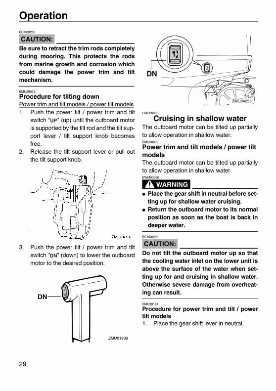
Cruising in shallow waterThe outboard motor can be tilted up partiallyto allow operation in shallow water.EMU28090
Power trim and tilt models / power tilt modelsThe outboard motor can be tilted up partiallyto allow operation in shallow water.
WARNINGEWM00660
� Place the gear shift in neutral before set-ting up for shallow water cruising.
� Return the outboard motor to its normalposition as soon as the boat is back indeeper water.
CAUTION:ECM00260
Do not tilt the outboard motor up so thatthe cooling water inlet on the lower unit isabove the surface of the water when set-ting up for and cruising in shallow water.Otherwise severe damage from overheat-ing can result.
EMU28184
Procedure for power trim and tilt / powertilt models1. Place the gear shift lever in neutral.
DN
ZMU01936
UP
DN
DN
ZMU04255
U6D770E0.book Page 29 Tuesday, October 12, 2004 5:00 PM
Operation
30
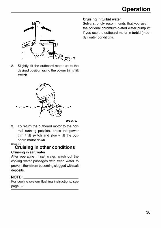
2. Slightly tilt the outboard motor up to thedesired position using the power trim / tiltswitch.
3. To return the outboard motor to the nor-mal running position, press the powertrim / tilt switch and slowly tilt the out-board motor down.
EMU28190
Cruising in other conditionsCruising in salt waterAfter operating in salt water, wash out thecooling water passages with fresh water toprevent them from becoming clogged with saltdeposits.
NOTE:For cooling system flushing instructions, seepage 32.
Cruising in turbid waterSelva strongly recommends that you usethe optional chromium-plated water pump kitif you use the outboard motor in turbid (mud-dy) water conditions.
U6D770E0.book Page 30 Tuesday, October 12, 2004 5:00 PM

Maintenance
31
EMU28216
SpecificationsDimension:
Overall length:Marlin 100: 817 mm - Narwhal 115: 825 mm
Overall width:Marlin 100: 479 mm - Narwhal 115: 491 mm
Overall height L:Marlin 100: 1582 mm - Narwhal 115: 1609 mm
Overall height X:Marlin 100: 1710 mm - Narwhal 115: 1737 mm
Transom height L:Marlin 100: 536 mm - Narwhal 115: 516 mm
Transom height X:Marlin 100: 664 mm - Narwhal 115: 643 mm
Weight L:Marlin 100: 170 Kg - Narwhal 115: 194 Kg
Weight X:Marlin 100: 174 Kg - Narwhal 115: 199 Kg
Performance:Full throttle operating range:
5000–6000 r/minMaximum output:
Marlin 100: 73.6 kW@5500 r/min (100 HP@5500 r/min)
Narwhal 115 : 86.4 kW@5500 r/min (115 HP@5500 r/min)
Idling speed (in neutral):Marlin 100: 700 ±50 r/min - Narwhal 115: 750 ±50 r/min
Engine:Type:
4-stroke LDisplacement:
Marlin 100: 1596 cm³ - Narwhal 115: 1741 cm³ Bore × stroke:
Marlin 100: 79 × 81.4 mm - Narwhal 115: 79 × 88.8 mm Ignition system:
TCISpark plug (NGK):
Marlin 100: LFR5A-11 - Narwhal 115: LFR6A-11Spark plug gap:
1.0–1.1 mm Control system:
Remote control
Starting system:Electric
Starting carburetion system:Electronic fuel injection
Valve clearance (cold engine) IN:0.17–0.23 mm
Valve clearance (cold engine) EX:0.31–0.37 mm
Min. cold cranking amps (CCA/EN):430.0 A
Min. rated capacity (20HR/IEC):70.0 Ah
Alternator output for battery DC:25.0 A
Drive unit:Gear positions:
Forward-neutral-reverseGear ratio:
Marlin 100: 2.31 (30/13) - Narwhal 115: 2.15 (28/13)Trim and tilt system:
Power trim and tiltPropeller mark:
KFuel and oil:
Recommended fuel:Regular unleaded gasoline
Min. research octane:90
Recommended engine oil:4-stroke outboard motor oil
Engine oil grade API:API SE, SF, SG, SH, SJ
Engine oil type SAE:SAE10W30 or SAE10W40
Lubrication:Wet sump
Engine oil quantity (excluding oil filter):Marlin 100: 4,3 L - Narwhal 115: 4,5 L
Recommended gear oil:Hypoid gear oil SAE#90
Gear oil quantity:Marlin 100: 670 cm³ - Narwhal 115: 760 cm³
Tightening torque for engine:Spark plug:
25.0 Nm (18.4 ft-lb) (2.55 kgf-m)Propeller nut:
35.0 Nm (25.8 ft-lb) (3.57 kgf-m)
U6D770E0.book Page 31 Tuesday, October 12, 2004 5:00 PM
Maintenance
32
Engine oil drain bolt:28.0 Nm (20.7 ft-lb) (2.86 kgf-m)
Engine oil filter:18.0 Nm (13.3 ft-lb) (1.84 kgf-m)
EMU28222
Transporting and storing outboard motor
WARNINGEWM00690
� Leaking fuel is a fire hazard. When trans-porting and storing the outboard motor,close the air vent screw and fuel cock toprevent fuel from leaking.
� USE CARE when transporting fuel tank,whether in a boat or car.
� DO NOT fill fuel container to maximumcapacity. Gasoline will expand consider-ably as it warms up and can build uppressure in the fuel container. This cancause fuel leakage and a potential firehazard.
WARNINGEWM00700
Never get under the lower unit while it istilted, even if a motor support bar is used.Severe injury could occur if the outboardmotor accidentally falls.
CAUTION:ECM00660
Do not use the tilt support lever or knobwhen trailering the boat. The outboard mo-tor could shake loose from the tilt supportand fall. If the motor cannot be trailered inthe normal running position, use an addi-tional support device to secure it in the tiltposition.
The outboard motor should be trailered andstored in the normal running position. If thereis insufficient road clearance in this position,then trailer the outboard motor in the tilt posi-
tion using a motor support device such as atransom saver bar. Consult your Selvadealer for further details.EMU30041
Storing outboard motorWhen storing your Selva outboard motorfor prolonged periods of time (2 months orlonger), several important procedures mustbe performed to prevent excessive damage. Itis advisable to have your outboard motor ser-viced by an authorized Selva dealer prior tostorage. However, you, the owner, with a min-imum of tools, can perform the following pro-cedures.
CAUTION:ECM01350
� To prevent problems which can becaused by oil entering the cylinder fromthe sump, keep the outboard motor inthe attitude shown when transportingand storing it. Do not store or transportthe outboard motor on its side (not up-right).
� Do not place the outboard motor on itsside before the cooling water hasdrained from it completely, otherwisewater may enter the cylinder through theexhaust port and cause engine trouble.
� Store the outboard motor in a dry, well-ventilated place, not in direct sunlight.
� Drain the remaining gasoline from thevapor separator. Gasoline left in the va-por separator for a prolonged period oftime will break down and could causedamage to the fuel line.
U6D770E0.book Page 32 Tuesday, October 12, 2004 5:00 PM

Maintenance
33
EMU28301
ProcedureEMU29953
Flushing with the flushing attachment1. Wash the outboard motor body using
fresh water. For further information, seepage 36.
2. Disconnect the fuel line from the motor orshut off the fuel cock, if equipped.
3. Remove the top cowling and propeller.4. Install the flushing attachment over the
cooling water inlet.
CAUTION:ECM00300
Do not run the engine without supplying itwith cooling water. Either the engine waterpump will be damaged or the engine willbe damaged from overheating. Beforestarting the engine, be sure to supply wa-ter to the cooling water passages.
CAUTION:ECM00310
Avoid running the outboard motor at highspeed while on the flushing attachment,otherwise overheating could occur.
5. Cooling system flushing is essential toprevent the cooling system from cloggingup with salt, sand, or dirt. In addition, fog-ging/lubricating the engine is mandatoryto prevent excessive engine damage dueto rust. Perform the flushing and foggingat the same time.
WARNINGEWM00090
� Do not touch or remove electrical partswhen starting or during operation.
� Keep hands, hair, and clothes away fromthe flywheel and other rotating partswhile the engine is running.
NOTE:� When using the flushing attachment, main-
tain adequate water pressure and a steadywater flow.
� If the overheat warning device is activated,turn the engine off, and consult yourSelva dealer.
6. Run the engine at a fast idle for a fewminutes in neutral position.
7. Just prior to turning off the engine, quicklyspray “Fogging Oil” alternately into the in-take silencer or the fogging hole of the si-lencer cover, if equipped. When properlydone, the engine will smoke excessivelyand almost stall.
ZMU03659
1. Flushing attachment
U6D770E0.book Page 33 Tuesday, October 12, 2004 5:00 PM

Maintenance
34
8. Drain the remained gasoline in the vaporseparator with a container. Loosen thedrain screw, and then remove the cap.Push in the air valve with a screwdriver tointroduce air into the float chamber, sothat the gasoline will drain smoothly.Then, tighten the drain screw.
9. Remove the flushing attachment.10. Install the top cowling.11. If “Fogging Oil” is not available, turn off
the engine after the 6 step. Then performthe 8 step procedure.
12. Drain the cooling water completely out ofthe motor. Clean the body thoroughly.
13. If the “Fogging Oil” is not available, re-move the spark plug(s). Pour a teaspoon-ful of clean engine oil into each cylinder.Crank several times manually. Replacethe spark plug(s).
NOTE:A flushing attachment is available from yourSelva dealer.
EMU28400
Lubrication (except oil injection models)1. Grease the spark plug threads and install
the spark plug(s) and torque to properspecification. For information on sparkplug installation, see page 39.
2. Change the gear oil. For instructions, seepage 47. Inspect the oil for the presenceof water that indicates a leaky seal. Sealreplacement should be performed by anauthorized Selva dealer prior to use.
3. Grease all grease fittings. For further de-tails, see page 39.
EMU28430
Battery care
WARNINGEWM00330
Battery electrolytic fluid is dangerous; itcontains sulfuric acid and therefore is poi-sonous and highly caustic.Always follow these preventive measures:� Avoid bodily contact with electrolytic
fluid as it can cause severe burns or per-manent eye injury.
� Wear protective eye gear when handlingor working near batteries.
Antidote (EXTERNAL):� SKIN - Flush with water.� EYES - Flush with water for 15 minutes
and get immediate medical attention.Antidote (INTERNAL):
1. Vapor separator2. Drain screw3. Cap
1. Air valve
U6D770E0.book Page 34 Tuesday, October 12, 2004 5:00 PM
Maintenance
35
� Drink large quantities of water or milkfollowed by milk of magnesia, beatenegg, or vegetable oil. Get immediatemedical attention.
Batteries also generate explosive hydro-gen gas; therefore, you should always fol-low these preventive measures:� Charge batteries in a well-ventilated ar-
ea.� Keep batteries away from fire, sparks, or
open flames (for example: weldingequipment, lighted cigarettes, and soon.)
� DO NOT SMOKE when charging or han-dling batteries.
KEEP BATTERIES AND ELECTROLYTICFLUID OUT OF REACH OF CHILDREN.
Batteries vary among manufacturers. There-fore the following procedures may not alwaysapply. Consult your battery manufacturer’s in-structions.Procedure1. Disconnect and remove the battery from
the boat. Always disconnect the blacknegative cable first to prevent the risk ofshorting.
2. Clean the battery casing and terminals.Fill each cell to the upper level with dis-tilled water.
3. Store the battery on a level surface in acool, dry, well-ventilated place out of di-rect sunlight.
4. Once a month, check the specific gravityof the electrolyte and recharge as re-quired to prolong battery life.
EMU28440
Flushing power unitPerform this procedure right after operationfor the most thorough flushing.
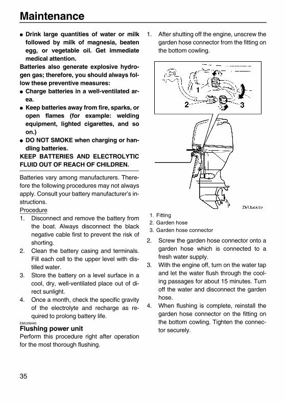
1. After shutting off the engine, unscrew thegarden hose connector from the fitting onthe bottom cowling.
2. Screw the garden hose connector onto agarden hose which is connected to afresh water supply.
3. With the engine off, turn on the water tapand let the water flush through the cool-ing passages for about 15 minutes. Turnoff the water and disconnect the gardenhose.
4. When flushing is complete, reinstall thegarden hose connector on the fitting onthe bottom cowling. Tighten the connec-tor securely.
1. Fitting2. Garden hose3. Garden hose connector
U6D770E0.book Page 35 Tuesday, October 12, 2004 5:00 PM
Maintenance
36
CAUTION:ECM00540
Do not leave the garden hose connectorloose on the bottom cowling fitting or letthe hose hang free during normal opera-tion. Water will leak out of the connectorinstead of cooling the engine, which cancause serious overheating. Be sure theconnector is tightened securely on the fit-ting after flushing the engine.
NOTE:� When flushing the engine with the boat in
the water, tilting up the outboard motor untilit is completely out of the water will achievebetter results.
� For cooling system flushing instructions,see page 32.
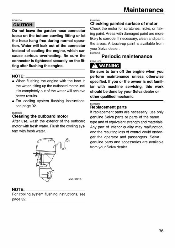
EMU28450
Cleaning the outboard motorAfter use, wash the exterior of the outboardmotor with fresh water. Flush the cooling sys-tem with fresh water.
NOTE:For cooling system flushing instructions, seepage 32.
EMU28460
Checking painted surface of motorCheck the motor for scratches, nicks, or flak-ing paint. Areas with damaged paint are morelikely to corrode. If necessary, clean and paintthe areas. A touch-up paint is available fromyour Selva dealer.EMU28476
Periodic maintenance
WARNINGEWM01070
Be sure to turn off the engine when youperform maintenance unless otherwisespecified. If you or the owner is not famil-iar with machine servicing, this workshould be done by your Selva dealer orother qualified mechanic.
EMU28510
Replacement partsIf replacement parts are necessary, use onlygenuine Selva parts or parts of the sametype and of equivalent strength and materials.Any part of inferior quality may malfunction,and the resulting loss of control could endan-ger the operator and passengers. Selvagenuine parts and accessories are availablefrom your Selva dealer.
ZMU04265
U6D770E0.book Page 36 Tuesday, October 12, 2004 5:00 PM

Maintenance
37
EMU30560
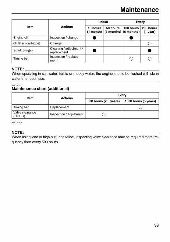
Maintenance chart
NOTE:� Refer to the sections in this chapter for explanations of each owner-specific action.� The maintenance cycle on these charts assume usage of 200 hours per year. Maintenance
frequency should be adjusted according to usage conditions.� Disassembly or repairs may be necessary depending on the outcome of maintenance
checks.� Expendable or consumable parts and lubricants will lose their effectiveness over time and
through normal usage regardless of the warranty period.
The “ ” symbol indicates the check-ups which you may carry out yourself.The “ ” symbol indicates work to be carried out by your Selva dealer.
Item Actions
Initial Every
10 hours (1 month)
50 hours (3 months)
100 hours (6 months)
200 hours (1 year)
Anode(s) (external) Inspection / replace-ment
Anode(s) (internal) Inspection / replace-ment
Battery Inspection / charging
Cooling water passag-es Cleaning
Cowling clamp Inspection
Fuel filter (can be dis-assembled) Inspection / cleaning
Fuel system Inspection
Gear oil Change
Greasing points Greasing
Idling speed (EFI mod-els) Inspection / adjustment
PCV (Pressure Con-trol Valve) Inspection
Power trim and tilt unit Inspection
Propeller and cotter pin Inspection / replace-ment
Shift link / shift cable Inspection / adjustment
Thermostat Inspection
Throttle link / throttle cable / throttle pick-up timing
Inspection / adjustment
Water pump Inspection
U6D770E0.book Page 37 Tuesday, October 12, 2004 5:00 PM
Maintenance
38
NOTE:When operating in salt water, turbid or muddy water, the engine should be flushed with cleanwater after each use.
EMU28871
Maintenance chart (additional)
EMU28910
NOTE:When using lead or high-sulfur gasoline, inspecting valve clearance may be required more fre-quently than every 500 hours.
Engine oil Inspection / change
Oil filter (cartridge) Change
Spark plug(s) Cleaning / adjustment / replacement
Timing belt Inspection / replace-ment
Item ActionsEvery
500 hours (2.5 years) 1000 hours (5 years)
Timing belt Replacement
Valve clearance (DOHC) Inspection / adjustment
Item Actions
Initial Every
10 hours (1 month)
50 hours (3 months)
100 hours (6 months)
200 hours (1 year)
U6D770E0.book Page 38 Tuesday, October 12, 2004 5:00 PM

Maintenance
39
EMU28940
GreasingSelva grease (water resistant grease)Selva grease (corrosion resistant grease; for propeller shaft)
EMU28951
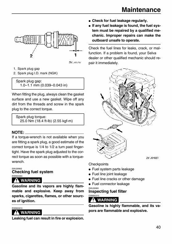
Cleaning and adjusting spark plug
WARNINGEWM00560
When removing or installing a spark plug,be careful not to damage the insulator. Adamaged insulator could allow externalsparks, which could lead to explosion orfire.
The spark plug is an important engine compo-nent and is easy to inspect. The condition ofthe spark plug can indicate something aboutthe condition of the engine. For example, if thecenter electrode porcelain is very white, thiscould indicate an intake air leak or carburetionproblem in that cylinder. Do not attempt to di-
agnose any problems yourself. Instead, takethe outboard motor to a Selva dealer. Youshould periodically remove and inspect thespark plug because heat and deposits willcause the spark plug to slowly break downand erode. If electrode erosion becomes ex-cessive, or if carbon and other deposits areexcessive, you should replace the spark plugwith another of the correct type.
Before fitting the spark plug, measure theelectrode gap with a wire thickness gauge;adjust the gap to specification if necessary.
ZMU04266
U6D770E0.book Page 39 Tuesday, October 12, 2004 5:00 PM
Maintenance
40
When fitting the plug, always clean the gasketsurface and use a new gasket. Wipe off anydirt from the threads and screw in the sparkplug to the correct torque.
NOTE:If a torque-wrench is not available when youare fitting a spark plug, a good estimate of thecorrect torque is 1/4 to 1/2 a turn past finger-tight. Have the spark plug adjusted to the cor-rect torque as soon as possible with a torque-wrench.
EMU28962
Checking fuel system
WARNINGEWM00060
Gasoline and its vapors are highly flam-mable and explosive. Keep away fromsparks, cigarettes, flames, or other sourc-es of ignition.
WARNINGEWM00910
Leaking fuel can result in fire or explosion.
� Check for fuel leakage regularly.� If any fuel leakage is found, the fuel sys-
tem must be repaired by a qualified me-chanic. Improper repairs can make theoutboard unsafe to operate.
Check the fuel lines for leaks, crack, or mal-function. If a problem is found, your Selvadealer or other qualified mechanic should re-pair it immediately.
Checkpoints� Fuel system parts leakage� Fuel line joint leakage� Fuel line cracks or other damage� Fuel connector leakageEMU28980
Inspecting fuel filter
WARNINGEWM00310
Gasoline is highly flammable, and its va-pors are flammable and explosive.
1. Spark plug gap2. Spark plug I.D. mark (NGK)
Spark plug gap:1.0–1.1 mm (0.039–0.043 in)
Spark plug torque:25.0 Nm (18.4 ft-lb) (2.55 kgf-m)
U6D770E0.book Page 40 Tuesday, October 12, 2004 5:00 PM
Maintenance
41
� If you have any question about properlydoing this procedure, consult yourSelva dealer.
� Do not perform this procedure on a hotor running engine. Allow the engine tocool.
� There will be fuel in the fuel filter. Keepaway from sparks, cigarettes, flames orother sources of ignition.
� This procedure will allow some fuel tospill. Catch fuel in a rag. Wipe up anyspilled fuel immediately.
� The fuel filter must be reassembledcarefully with the O-ring, filter cup, andhoses in place. Improper assembly orreplacement could result in a fuel leak,which could result in a fire or explosionhazard.
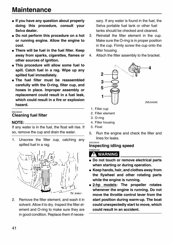
EMU30640
Cleaning fuel filter
NOTE:If any water is in the fuel, the float will rise. Ifso, remove the cup and drain the water.
1. Unscrew the filter cup, catching anyspilled fuel in a rag.
2. Remove the filter element, and wash it insolvent. Allow it to dry. Inspect the filter el-ement and O-ring to make sure they arein good condition. Replace them if neces-
sary. If any water is found in the fuel, theSelva portable fuel tank or other fueltanks should be checked and cleaned.
3. Reinstall the filter element in the cup.Make sure the O-ring is in proper positionin the cup. Firmly screw the cup onto thefilter housing.
4. Attach the filter assembly to the bracket.
5. Run the engine and check the filter andlines for leaks.
EMU29040
Inspecting idling speed
WARNINGEWM00450
� Do not touch or remove electrical partswhen starting or during operation.
� Keep hands, hair, and clothes away fromthe flywheel and other rotating partswhile the engine is running.
� 2-hp models: The propeller rotateswhenever the engine is running. Do notmove the throttle control lever from thestart position during warm-up. The boatcould unexpectedly start to move, whichcould result in an accident.
1. Filter cup2. Filter element3. O-ring4. Filter housing5. Float
1
3
24
5
ZMU04269
U6D770E0.book Page 41 Tuesday, October 12, 2004 5:00 PM
Maintenance
42
CAUTION:ECM00490
This procedure must be performed whilethe outboard motor is in the water. A flush-ing attachment or test tank can be used.
A diagnostic tachometer should be used forthis procedure. Results may vary dependingon whether testing is conducted with theflushing attachment, in a test tank, or with theoutboard motor in the water.1. Start the engine and allow it to warm up
fully in neutral until it is running smoothly.2-hp model: Warm the engine with thethrottle in the start position or less. If theoutboard is mounted on a boat, be surethe boat is tightly moored.
NOTE:Correct idling speed inspection is only possi-ble if the engine is fully warmed up. If notwarmed up fully, the idle speed will measurehigher than normal. If you have difficulty veri-fying the idle speed, or the idle speed requiresadjustment, consult a Selva dealer or otherqualified mechanic.
2. Verify whether the idle speed is set tospecification. For idle speed specifica-tions, see page 31.
EMU29073
Changing engine oil
WARNINGEWM00760
� Avoid draining the engine oil immediate-ly after stopping the engine. The oil ishot and should be handled with care toavoid burns.
� Be sure the outboard motor is securelyfastened to the transom or a stablestand.
CAUTION:ECM00970
� Do not overfill the oil, and be sure theoutboard motor is upright (not tilted)when checking and changing the engineoil.
� If the oil level is above the upper levelmark, drain until the level meets thespecified capacity. Overfilling the oilcould cause leakage or damage.
CAUTION:ECM01240
Change the engine oil after the first 10hours of operation, and every 100 hours orat 6-month intervals thereafter. Otherwisethe engine will wear quickly.
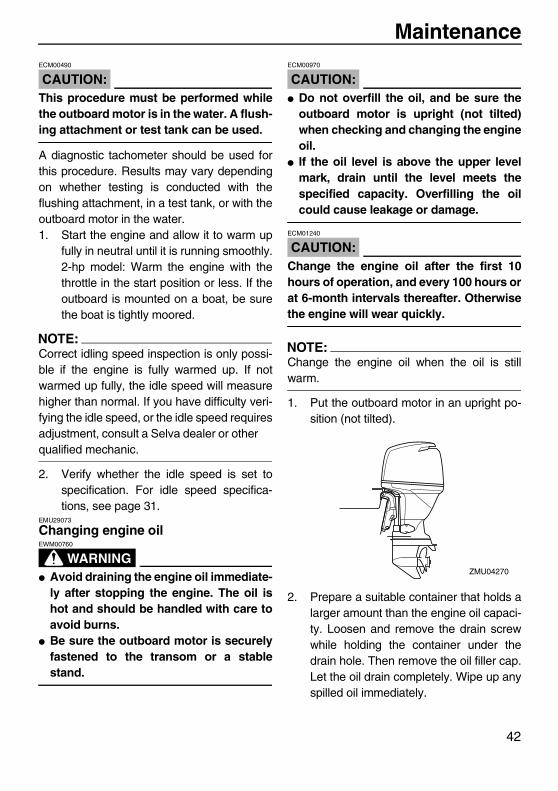
NOTE:Change the engine oil when the oil is stillwarm.
1. Put the outboard motor in an upright po-sition (not tilted).
2. Prepare a suitable container that holds alarger amount than the engine oil capaci-ty. Loosen and remove the drain screwwhile holding the container under thedrain hole. Then remove the oil filler cap.Let the oil drain completely. Wipe up anyspilled oil immediately.
ZMU04270
U6D770E0.book Page 42 Tuesday, October 12, 2004 5:00 PM

Maintenance
43
3. Put a new gasket on the oil drain screw.Apply a light coat of oil to the gasket andinstall the drain screw.
NOTE:If a torque wrench is not available when youare installing the drain screw, finger tightenthe screw just until the gasket comes into con-tact with the surface of the drain hole. Thentighten 1/4 to 1/2 turn more. Tighten the drainscrew to the correct torque with a torquewrench as soon as possible.
4. Add the correct amount of oil through thefiller hole. Install the filler cap.
5. Start the engine and watch to make surethe low oil pressure warning indicator (ifequipped) turns off. Make sure that thereare no oil leaks.
CAUTION:ECM00680
If the low oil pressure warning indicatordoes not turn off or if there are oil leaks,stop the engine and find the cause. Con-tinued operation with a problem couldcause severe engine damage. Consultyour Selva dealer if the problem cannotbe located and corrected.
6. Turn off the engine and wait 3 minutes.Recheck the oil level using the dipstick tobe sure the level falls between the upperand lower marks. Fill with oil if it is belowthe lower mark, or drain to the specifiedlevel if it is above the upper mark.
1. Drain screw
Drain screw tightening torque:28.0 Nm (20.7 ft-lb) (2.86 kgf-m)
Recommended engine oil:4-stroke outboard motor oil
1
ZMU04241
1. Oil filler cap
1. Lower level mark
1
ZMU04271
U6D770E0.book Page 43 Tuesday, October 12, 2004 5:00 PM
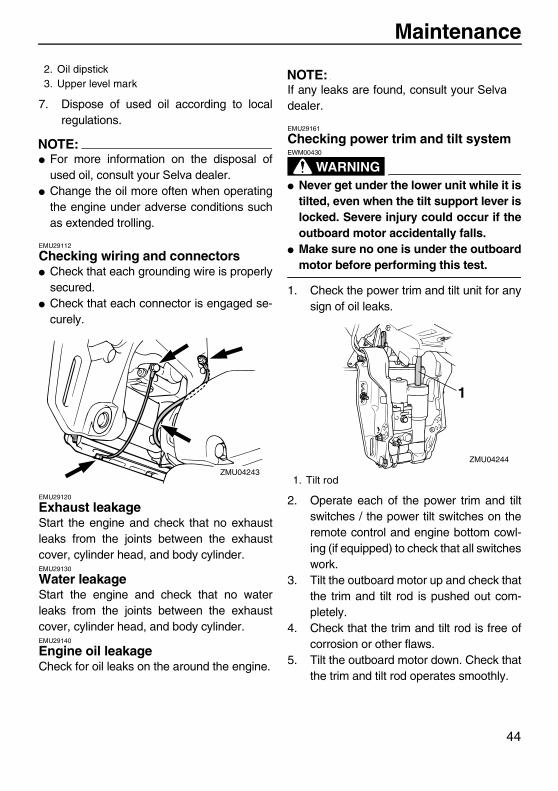
Maintenance
44
7. Dispose of used oil according to localregulations.
NOTE:� For more information on the disposal of
used oil, consult your Selva dealer.� Change the oil more often when operating
the engine under adverse conditions suchas extended trolling.
EMU29112
Checking wiring and connectors� Check that each grounding wire is properly
secured.� Check that each connector is engaged se-
curely.
EMU29120
Exhaust leakageStart the engine and check that no exhaustleaks from the joints between the exhaustcover, cylinder head, and body cylinder.EMU29130
Water leakageStart the engine and check that no waterleaks from the joints between the exhaustcover, cylinder head, and body cylinder.EMU29140
Engine oil leakageCheck for oil leaks on the around the engine.
NOTE:If any leaks are found, consult your Selvadealer.
EMU29161
Checking power trim and tilt system
WARNINGEWM00430
� Never get under the lower unit while it istilted, even when the tilt support lever islocked. Severe injury could occur if theoutboard motor accidentally falls.
� Make sure no one is under the outboardmotor before performing this test.
1. Check the power trim and tilt unit for anysign of oil leaks.
2. Operate each of the power trim and tiltswitches / the power tilt switches on theremote control and engine bottom cowl-ing (if equipped) to check that all switcheswork.
3. Tilt the outboard motor up and check thatthe trim and tilt rod is pushed out com-pletely.
4. Check that the trim and tilt rod is free ofcorrosion or other flaws.
5. Tilt the outboard motor down. Check thatthe trim and tilt rod operates smoothly.
2. Oil dipstick3. Upper level mark
ZMU042431. Tilt rod
1
ZMU04244
U6D770E0.book Page 44 Tuesday, October 12, 2004 5:00 PM
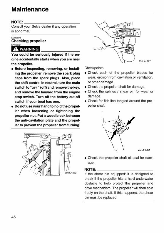
Maintenance
45
NOTE:Consult your Selva dealer if any operationis abnormal.
EMU29171
Checking propeller
WARNINGEWM00321
You could be seriously injured if the en-gine accidentally starts when you are nearthe propeller.� Before inspecting, removing, or install-
ing the propeller, remove the spark plugcaps from the spark plugs. Also, placethe shift control in neutral, turn the mainswitch to “ ” (off) and remove the key,and remove the lanyard from the enginestop switch. Turn off the battery cut-offswitch if your boat has one.
� Do not use your hand to hold the propel-ler when loosening or tightening thepropeller nut. Put a wood block betweenthe anti-cavitation plate and the propel-ler to prevent the propeller from turning.
Checkpoints� Check each of the propeller blades for
wear, erosion from cavitation or ventilation,or other damage.
� Check the propeller shaft for damage.� Check the splines / shear pin for wear or
damage.� Check for fish line tangled around the pro-
peller shaft.
� Check the propeller shaft oil seal for dam-age.
NOTE:If the shear pin equipped: it is designed tobreak if the propeller hits a hard underwaterobstacle to help protect the propeller anddrive mechanism. The propeller will then spinfreely on the shaft. If this happens, the shearpin must be replaced.
ZMU04262
ZMU01897
U6D770E0.book Page 45 Tuesday, October 12, 2004 5:00 PM
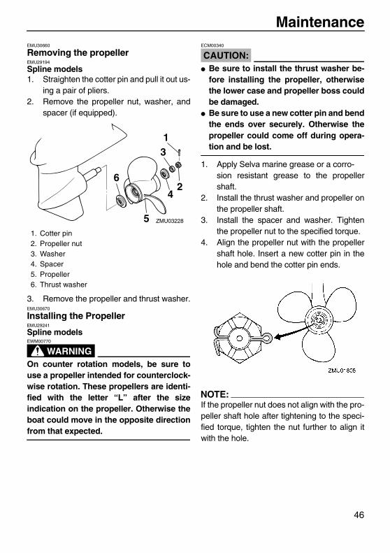
Maintenance
46
EMU30660
Removing the propellerEMU29194
Spline models1. Straighten the cotter pin and pull it out us-
ing a pair of pliers.2. Remove the propeller nut, washer, and
spacer (if equipped).
3. Remove the propeller and thrust washer.EMU30670
Installing the PropellerEMU29241
Spline models
WARNINGEWM00770
On counter rotation models, be sure touse a propeller intended for counterclock-wise rotation. These propellers are identi-fied with the letter “L” after the sizeindication on the propeller. Otherwise theboat could move in the opposite directionfrom that expected.
CAUTION:ECM00340
� Be sure to install the thrust washer be-fore installing the propeller, otherwisethe lower case and propeller boss couldbe damaged.
� Be sure to use a new cotter pin and bendthe ends over securely. Otherwise thepropeller could come off during opera-tion and be lost.
1. Apply Selva marine grease or a corro-sion resistant grease to the propellershaft.
2. Install the thrust washer and propeller onthe propeller shaft.
3. Install the spacer and washer. Tightenthe propeller nut to the specified torque.
4. Align the propeller nut with the propellershaft hole. Insert a new cotter pin in thehole and bend the cotter pin ends.
NOTE:If the propeller nut does not align with the pro-peller shaft hole after tightening to the speci-fied torque, tighten the nut further to align itwith the hole.
1. Cotter pin2. Propeller nut3. Washer4. Spacer5. Propeller6. Thrust washer
ZMU03228
1
2
3
4
5
6
U6D770E0.book Page 46 Tuesday, October 12, 2004 5:00 PM

Maintenance
47
EMU29281
Changing gear oil
WARNINGEWM00800
� Be sure the outboard motor is securelyfastened to the transom or a stablestand. You could be severely injured ifthe outboard motor falls on you.
� Never get under the lower unit while it istilted, even when the tilt support lever orknob is locked. Severe injury could oc-cur if the outboard motor accidentallyfalls.
1. Tilt the outboard motor so that the gear oildrain screw is at the lowest point possi-ble.
2. Place a suitable container under the gearcase.
3. Remove the gear oil drain screw.
NOTE:If the magnetic gear oil drain screw equipped:remove all metal particles from the screw be-fore installing it.
4. Remove the oil level plug to allow the oilto drain completely.
CAUTION:ECM00710
Inspect the used oil after it has beendrained. If the oil is milky, water is gettinginto the gear case which can cause geardamage. Consult a Selva dealer for re-pair of the lower unit seals.
NOTE:For disposal of used oil consult your Selvadealer.
5. With the outboard motor in a vertical po-sition, and using a flexible or pressurizedfilling device, inject the gear oil into thegear oil drain screw hole.
6. When the oil begins to flow out of the oillevel plug hole, insert and tighten the oillevel plug.
7. Insert and tighten the gear oil drainscrew.
1. Gear oil drain screw2. Oil level plug
ZMU03273
2
1
Recommended gear oil:Hypoid gear oil SAE#90
ZMU03274
U6D770E0.book Page 47 Tuesday, October 12, 2004 5:00 PM

Maintenance
48
EMU29302
Cleaning fuel tank
WARNINGEWM00920
Gasoline is highly flammable, and its va-pors are flammable and explosive.� If you have any question about properly
doing this procedure, consult yourSelva dealer.
� Keep away from sparks, cigarettes,flames, or other sources of ignitionwhen cleaning the fuel tank.
� Remove the fuel tank from the boat be-fore cleaning it. Work only outdoors inan area with good ventilation.
� Wipe up any spilled fuel immediately.� Reassemble the fuel tank carefully. Im-
proper assembly can result in a fuelleak, which could result in a fire or ex-plosion hazard.
� Dispose of old gasoline according to lo-cal regulations.
1. Empty the fuel tank into an approved con-tainer.
2. Pour a small amount of suitable solventinto the tank. Install the cap and shakethe tank. Drain the solvent completely.
3. Remove the screws holding the fuel jointassembly. Pull the assembly out of thetank.
4. Clean the filter (located on the end of thesuction pipe) in a suitable cleaning sol-vent. Allow the filter to dry.
5. Replace the gasket with a new one. Re-install the fuel joint assembly and tightenthe screws firmly.
EMU29312
Inspecting and replacing anode(s)Selva outboard motors are protected fromcorrosion by sacrificial anodes. Inspect theexternal anodes periodically. Remove scalesfrom the surfaces of the anodes. Consult aSelva dealer for replacement of externalanodes.
CAUTION:ECM00720
Do not paint anodes, as this would renderthem ineffective.
NOTE:Inspect ground leads attached to external an-odes on equipped models. Consult a Selvadealer for inspection and replacement of inter-nal anodes attached to the power unit.
ZMU02066
U6D770E0.book Page 48 Tuesday, October 12, 2004 5:00 PM

Maintenance
49
EMU29320
Checking battery (for electric start models)
WARNINGEWM00330
Battery electrolytic fluid is dangerous; itcontains sulfuric acid and therefore is poi-sonous and highly caustic.Always follow these preventive measures:� Avoid bodily contact with electrolytic
fluid as it can cause severe burns or per-manent eye injury.
� Wear protective eye gear when handlingor working near batteries.
Antidote (EXTERNAL):� SKIN - Flush with water.� EYES - Flush with water for 15 minutes
and get immediate medical attention.Antidote (INTERNAL):� Drink large quantities of water or milk
followed by milk of magnesia, beatenegg, or vegetable oil. Get immediatemedical attention.
Batteries also generate explosive hydro-gen gas; therefore, you should always fol-low these preventive measures:� Charge batteries in a well-ventilated ar-
ea.� Keep batteries away from fire, sparks, or
open flames (for example: weldingequipment, lighted cigarettes, and soon.)
� DO NOT SMOKE when charging or han-dling batteries.
KEEP BATTERIES AND ELECTROLYTICFLUID OUT OF REACH OF CHILDREN.
CAUTION:ECM00360
� A poorly maintained battery will quicklydeteriorate.
� Ordinary tap water contains mineralsharmful to a battery, and should not beused for topping up.
1. Check the electrolyte level at least once amonth. Fill to the manufacturer’s recom-mended level when necessary. Top uponly with distilled water (or pure de-ion-ized water suitable to use in batteries).
2. Always keep the battery in a good state ofcharge. Installing a voltmeter will helpyou monitor your battery. If you will notuse the boat for a month or more, removethe battery from the boat and store it in acool, dark place. Completely rechargethe battery before using it.
3. If the battery will be stored for longer thana month, check the specific gravity of thefluid at least once a month and rechargethe battery when it is low.
ZMU04245
U6D770E0.book Page 49 Tuesday, October 12, 2004 5:00 PM

Maintenance
50
NOTE:Consult a Selva dealer when charging orre-charging batteries.
EMU29331
Connecting the battery
WARNINGEWM00570
Mount the battery holder securely in a dry,well-ventilated, vibration-free location inthe boat. Install a fully charged battery inthe holder.
CAUTION:ECM01121
� Make sure the main switch (on applica-ble models) is “ ” (off) before workingon the battery.
� Reversal of the battery cables will dam-age the electrical parts.
� Connect the red battery cable first wheninstalling the battery and disconnect theblack battery cable first when removingit. Otherwise, the electrical parts can bedamaged.
� The electrical contacts of the batteryand cables must be clean and properlyconnected, or the battery will not startthe engine.
Connect the red battery cable to the POSI-TIVE (+) terminal first. Then connect the blackbattery cable to the NEGATIVE (-) terminal.
EMU29370
Disconnecting the batteryDisconnect the BLACK cable from the NEGA-TIVE (-) terminal first. Then disconnect theRED cable from the POSITIVE (+) terminal.EMU29390
Checking top cowlingCheck the fitting of the top cowling by pushingit with both hands. If it is loose have it repairedby your Selva dealer.
EMU29400
Coating the boat bottomA clean hull improves boat performance. Theboat bottom should be kept as clean of marinegrowth as possible. If necessary, the boat bot-tom can be coated with an anti-fouling paintapproved for your area to inhibit marinegrowth.
1. Red cable2. Black cable3. Battery
U6D770E0.book Page 50 Tuesday, October 12, 2004 5:00 PM

Maintenance
51
Do not use anti-fouling paint which includescopper or graphite. These paints can causemore rapid engine corrosion.
ZMU04246
U6D770E0.book Page 51 Tuesday, October 12, 2004 5:00 PM
Trouble Recovery
52
EMU29422
TroubleshootingA problem in the fuel, compression, or ignitionsystems can cause poor starting, loss of pow-er, or other problems. This section describesbasic checks and possible remedies, and cov-ers all Selva outboard motors. Thereforesome items may not apply to your model.If your outboard motor requires repair, bring itto your Selva dealer.If the engine trouble warning indicator is flash-ing, consult your Selva dealer.
Starter will not operate.Q. Is battery capacity weak or low?A. Check battery condition. Use battery of rec-ommended capacity.
Q. Are battery connections loose or corrod-ed?A. Tighten battery cables and clean batteryterminals.
Q. Is fuse for electric start relay or electric cir-cuit blown?A. Check for cause of electric overload andrepair. Replace fuse with one of correct am-perage.
Q. Are starter components faulty?A. Have serviced by a Selva dealer.
Q. Is shift lever in gear?A. Shift to neutral.
Engine will not start (starter operates).Q. Is fuel tank empty?A. Fill tank with clean, fresh fuel.
Q. Is fuel contaminated or stale?A. Fill tank with clean, fresh fuel.
Q. Is fuel filter clogged?A. Clean or replace filter.
Q. Is starting procedure incorrect?A. See page 22.
Q. Has fuel pump malfunctioned?A. Have serviced by a Selva dealer.
Q. Are spark plug(s) fouled or of incorrecttype?A. Inspect spark plug(s). Clean or replace withrecommended type.
Q. Are spark plug cap(s) fitted incorrectly?A. Check and re-fit cap(s).
Q. Is ignition wiring damaged or poorly con-nected?A. Check wires for wear or breaks. Tighten allloose connections. Replace worn or brokenwires.
Q. Are ignition parts faulty?A. Have serviced by a Selva dealer.
Q. Is engine stop switch lanyard not at-tached?A. Attach lanyard.
Q. Are engine inner parts damaged?A. Have serviced by a Selva dealer.
Engine idles irregularly or stalls.Q. Are spark plug(s) fouled or of incorrecttype?A. Inspect spark plug(s). Clean or replace withrecommended type.
Q. Is fuel system obstructed?
U6D770E0.book Page 52 Tuesday, October 12, 2004 5:00 PM
Trouble Recovery
53
A. Check for pinched or kinked fuel line or oth-er obstructions in fuel system.
Q. Is fuel contaminated or stale?A. Fill tank with clean, fresh fuel.
Q. Is fuel filter clogged?A. Clean or replace filter.
Q. Have ignition parts failed?A. Have serviced by a Selva dealer.
Q. Has warning system activated?A. Find and correct cause of warning.
Q. Is spark plug gap incorrect?A. Inspect and adjust as specified.
Q. Is ignition wiring damaged or poorly con-nected?A. Check wires for wear or breaks. Tighten allloose connections. Replace worn or brokenwires.
Q. Is specified engine oil not being used?A. Check and replace oil as specified.
Q. Is thermostat faulty or clogged?A. Have serviced by a Selva dealer.
Q. Are carburetor adjustments incorrect?A. Have serviced by a Selva dealer.
Q. Is fuel pump damaged?A. Have serviced by a Selva dealer.
Q. Is air vent screw on fuel tank closed?A. Open air vent screw.
Q. Is choke knob pulled out?
A. Return to home position.
Q. Is motor angle too high?A. Return to normal operating position.
Q. Is carburetor clogged?A. Have serviced by a Selva dealer.
Q. Is fuel joint connection incorrect?A. Connect correctly.
Q. Is throttle valve adjustment incorrect?A. Have serviced by a Selva dealer.
Q. Is battery cable disconnected?A. Connect securely.
Warning buzzer sounds or indicator lights.Q. Is cooling system clogged?A. Check water intake for restriction.
Q. Is engine oil level low?A. Fill oil tank with specified engine oil.
Q. Is heat range of spark plug incorrect?A. Inspect spark plug and replace it with rec-ommended type.
Q. Is specified engine oil not being used?A. Check and replace oil with specified type.
Q. Is engine oil contaminated or deteriorated?A. Replace oil with fresh, specified type.
Q. Is oil filter clogged?A. Have serviced by a Selva dealer.
Q. Has oil feed/injection pump malfunc-tioned?A. Have serviced by a Selva dealer.
U6D770E0.book Page 53 Tuesday, October 12, 2004 5:00 PM
Trouble Recovery
54
Q. Is load on boat improperly distributed?A. Distribute load to place boat on an evenplane.
Q. Is water pump or thermostat faulty?A. Have serviced by a Selva dealer.
Q. Is there excess water in fuel filter cup?A. Drain filter cup.
Engine power loss.Q. Is propeller damaged?A. Have propeller repaired or replaced.
Q. Is propeller pitch or diameter incorrect?A. Install correct propeller to operate outboardat its recommended speed (r/min) range.
Q. Is trim angle incorrect?A. Adjust trim angle to achieve most efficientoperation.
Q. Is motor mounted at incorrect height ontransom?A. Have motor adjusted to proper transomheight.
Q. Has warning system activated?A. Find and correct cause of warning.
Q. Is boat bottom fouled with marine growth?A. Clean boat bottom.
Q. Are spark plug(s) fouled or of incorrecttype?A. Inspect spark plug(s). Clean or replace withrecommended type.
Q. Are weeds or other foreign matter tangledon gear housing?
A. Remove foreign matter and clean lowerunit.
Q. Is fuel system obstructed?A. Check for pinched or kinked fuel line or oth-er obstructions in fuel system.
Q. Is fuel filter clogged?A. Clean or replace filter.
Q. Is fuel contaminated or stale?A. Fill tank with clean, fresh fuel.
Q. Is spark plug gap incorrect?A. Inspect and adjust as specified.
Q. Is ignition wiring damaged or poorly con-nected?A. Check wires for wear or breaks. Tighten allloose connections. Replace worn or brokenwires.
Q. Have ignition parts failed?A. Have serviced by a Selva dealer.
Q. Is specified engine oil not being used?A. Check and replace oil with specified type.
Q. Is thermostat faulty or clogged?A. Have serviced by a Selva dealer.
Q. Is air vent screw closed?A. Open the air vent screw.
Q. Is fuel pump damaged?A. Have serviced by a Selva dealer.
Q. Is fuel joint connection incorrect?A. Connect correctly.
Q. Is heat range of spark plug incorrect?
U6D770E0.book Page 54 Tuesday, October 12, 2004 5:00 PM
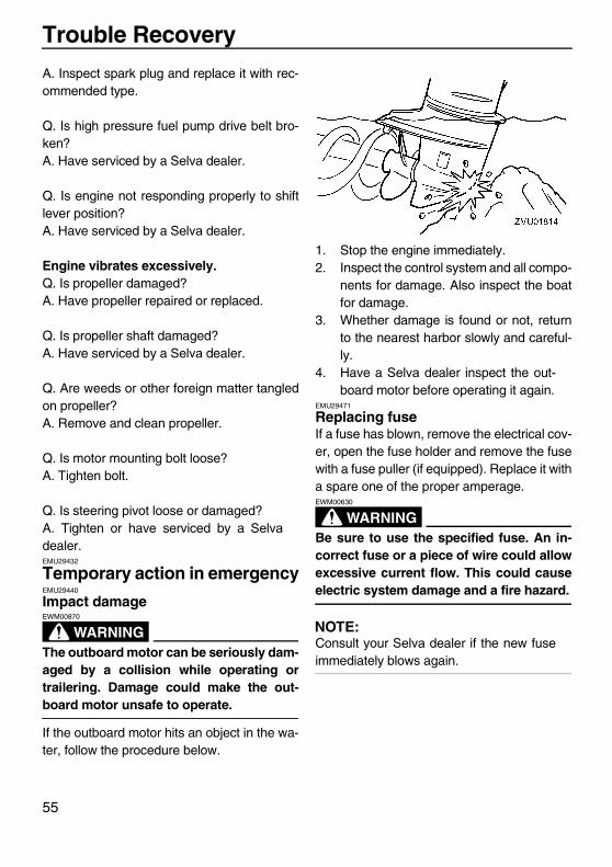
Trouble Recovery
55
A. Inspect spark plug and replace it with rec-ommended type.
Q. Is high pressure fuel pump drive belt bro-ken?A. Have serviced by a Selva dealer.
Q. Is engine not responding properly to shiftlever position?A. Have serviced by a Selva dealer.
Engine vibrates excessively.Q. Is propeller damaged?A. Have propeller repaired or replaced.
Q. Is propeller shaft damaged?A. Have serviced by a Selva dealer.
Q. Are weeds or other foreign matter tangledon propeller?A. Remove and clean propeller.
Q. Is motor mounting bolt loose?A. Tighten bolt.
Q. Is steering pivot loose or damaged?A. Tighten or have serviced by a Selvadealer.EMU29432
Temporary action in emergencyEMU29440
Impact damage
WARNINGEWM00870
The outboard motor can be seriously dam-aged by a collision while operating ortrailering. Damage could make the out-board motor unsafe to operate.
If the outboard motor hits an object in the wa-ter, follow the procedure below.
1. Stop the engine immediately.2. Inspect the control system and all compo-
nents for damage. Also inspect the boatfor damage.
3. Whether damage is found or not, returnto the nearest harbor slowly and careful-ly.
4. Have a Selva dealer inspect the out-board motor before operating it again.
EMU29471
Replacing fuseIf a fuse has blown, remove the electrical cov-er, open the fuse holder and remove the fusewith a fuse puller (if equipped). Replace it witha spare one of the proper amperage.
WARNINGEWM00630
Be sure to use the specified fuse. An in-correct fuse or a piece of wire could allowexcessive current flow. This could causeelectric system damage and a fire hazard.
NOTE:Consult your Selva dealer if the new fuseimmediately blows again.
U6D770E0.book Page 55 Tuesday, October 12, 2004 5:00 PM
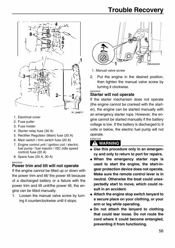
Trouble Recovery
56
EMU29520
Power trim and tilt will not operateIf the engine cannot be tilted up or down withthe power trim and tilt/ the power tilt becauseof a discharged battery or a failure with thepower trim and tilt unit/the power tilt, the en-gine can be tilted manually.1. Loosen the manual valve screw by turn-
ing it counterclockwise until it stops.
2. Put the engine in the desired position,then tighten the manual valve screw byturning it clockwise.
EMU29540
Starter will not operateIf the starter mechanism does not operate(the engine cannot be cranked with the start-er), the engine can be started manually withan emergency starter rope. However, the en-gine cannot be started manually if the batteryvoltage is low. If the battery is discharged to 9volts or below, the electric fuel pump will notoperate.
WARNINGEWM01020
� Use this procedure only in an emergen-cy and only to return to port for repairs.
� When the emergency starter rope isused to start the engine, the start-in-gear protection device does not operate.Make sure the remote control lever is inneutral. Otherwise the boat could unex-pectedly start to move, which could re-sult in an accident.
� Attach the engine stop switch lanyard toa secure place on your clothing, or yourarm or leg while operating.
� Do not attach the lanyard to clothingthat could tear loose. Do not route thecord where it could become entangled,preventing it from functioning.
1. Electrical cover2. Fuse puller3. Fuse holder4. Starter relay fuse (30 A)5. Rectifier Regulator (Main) fuse (20 A)6. Main switch / trim switch fuse (20 A)7. Engine control unit / ignition coil / electric
fuel pump / fuel injector / ISC (idle speed control) fuse (20 A)
8. Spare fuse (20 A, 30 A)
1. Manual valve screw
ZMU042491
U6D770E0.book Page 56 Tuesday, October 12, 2004 5:00 PM
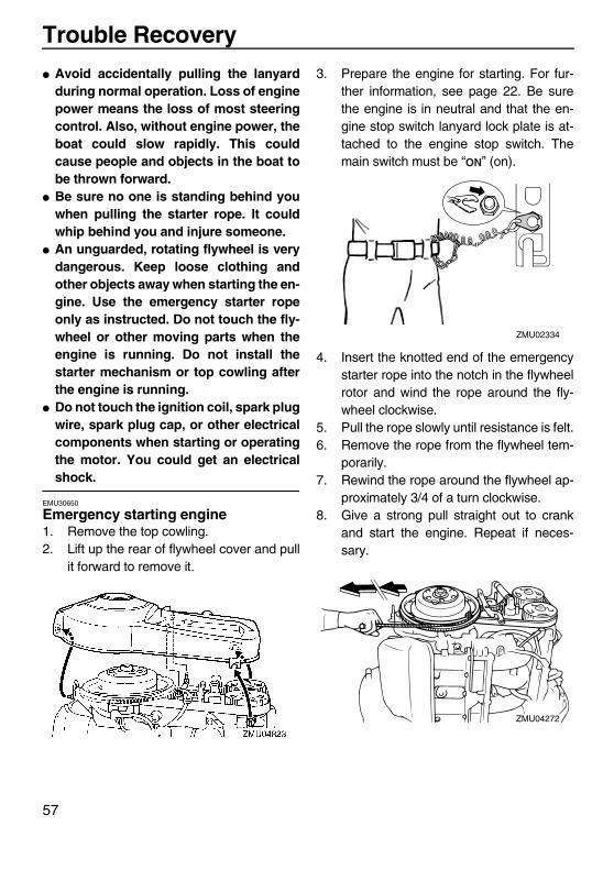
Trouble Recovery
57
� Avoid accidentally pulling the lanyardduring normal operation. Loss of enginepower means the loss of most steeringcontrol. Also, without engine power, theboat could slow rapidly. This couldcause people and objects in the boat tobe thrown forward.
� Be sure no one is standing behind youwhen pulling the starter rope. It couldwhip behind you and injure someone.
� An unguarded, rotating flywheel is verydangerous. Keep loose clothing andother objects away when starting the en-gine. Use the emergency starter ropeonly as instructed. Do not touch the fly-wheel or other moving parts when theengine is running. Do not install thestarter mechanism or top cowling afterthe engine is running.
� Do not touch the ignition coil, spark plugwire, spark plug cap, or other electricalcomponents when starting or operatingthe motor. You could get an electricalshock.
EMU30650
Emergency starting engine1. Remove the top cowling.2. Lift up the rear of flywheel cover and pull
it forward to remove it.
3. Prepare the engine for starting. For fur-ther information, see page 22. Be surethe engine is in neutral and that the en-gine stop switch lanyard lock plate is at-tached to the engine stop switch. Themain switch must be “ ” (on).
4. Insert the knotted end of the emergencystarter rope into the notch in the flywheelrotor and wind the rope around the fly-wheel clockwise.
5. Pull the rope slowly until resistance is felt.6. Remove the rope from the flywheel tem-
porarily.7. Rewind the rope around the flywheel ap-
proximately 3/4 of a turn clockwise.8. Give a strong pull straight out to crank
and start the engine. Repeat if neces-sary.
ZMU02334
ZMU04272
U6D770E0.book Page 57 Tuesday, October 12, 2004 5:00 PM
Trouble Recovery
58
EMU29760
Treatment of submerged motorIf the outboard motor is submerged, immedi-ately take it to a Selva dealer. Otherwisesome corrosion may begin almost immediate-ly.If you cannot immediately take the outboardmotor to a Selva dealer, follow the proce-dure below in order to minimize engine dam-age.EMU29790
Procedure1. Thoroughly wash away mud, salt, sea-
weed, and so on, with fresh water.2. Remove the spark plugs and face the
spark plug holes downward to allow anywater, mud, or contaminants to drain.
3. Drain the fuel from the vapor separator,fuel filter, and fuel line.
4. Feed fogging oil or engine oil through theintake manifold and spark plug holeswhile cranking with the emergency starterrope.
5. Take the outboard motor to a Selvadealer as soon as possible.
CAUTION:ECM00400
Do not attempt to run the outboard motoruntil it has been completely inspected.
U6D770E0.book Page 58 Tuesday, October 12, 2004 5:00 PM

www.selvamarine.com
SELVA S.p.A. Direzione e stabilimento principale / Head office and main factory: 23037 Tirano (Sondrio) - Italy - V.le dell’Industria, 13 Tel.0342/702451 - Fax 0342/705361 E-mail: [email protected] Filiale / Branch office: 20099 Sesto San Giovanni (MI) - Italy - Via Carducci, 221