
Hand Stencil Machine découpeuse de pochoirs...
29
Hand Stencil Machine Owner's Manual Manuel d'utilisation de la découpeuse de pochoirs manuelle Manual del propietario de la máquina cortadora de estarcidos de operación manual Marsh Shipping Supply Company, LLC, Collinsville, IL 62234 U.S.A.; Tel: 618.343.1006 Fax: 618.343.1016 25004 0703
Transcript of Hand Stencil Machine découpeuse de pochoirs...
Hand Stencil MachineOwner's Manual
Manuel d'utilisation de ladécoupeuse de pochoirs
manuelle
Manual del propietario dela máquina
cortadora de estarcidos deoperación manual
Marsh Shipping Supply Company, LLC, Collinsville, IL 62234 U.S.A.; Tel: 618.343.1006 Fax: 618.343.1016 25004 0703
125004/01138 Rev H
Table ofContents
Introduction . . . . . . . . . . . . . . . . . . . . . . . . . . . . . . . . . . . . . . . . 3
Installation . . . . . . . . . . . . . . . . . . . . . . . . . . . . . . . . . . . . . . . . . 5
Operation. . . . . . . . . . . . . . . . . . . . . . . . . . . . . . . . . . . . . . . . . . 7
Maintenance. . . . . . . . . . . . . . . . . . . . . . . . . . . . . . . . . . . . . . . 11
Troubleshooting . . . . . . . . . . . . . . . . . . . . . . . . . . . . . . . . . . . . 14
Repair. . . . . . . . . . . . . . . . . . . . . . . . . . . . . . . . . . . . . . . . . . . . 21
Parts List. . . . . . . . . . . . . . . . . . . . . . . . . . . . . . . . . . . . . . . . . . 32
Index . . . . . . . . . . . . . . . . . . . . . . . . . . . . . . . . . . . . . . . . . . . . 52
Table desmatières
Introduction . . . . . . . . . . . . . . . . . . . . . . . . . . . . . . . . . . . . . . . . 2
Installation . . . . . . . . . . . . . . . . . . . . . . . . . . . . . . . . . . . . . . . . . 4
Fonctionnement . . . . . . . . . . . . . . . . . . . . . . . . . . . . . . . . . . . . . 6
Entretien . . . . . . . . . . . . . . . . . . . . . . . . . . . . . . . . . . . . . . . . . 10
Dépannage . . . . . . . . . . . . . . . . . . . . . . . . . . . . . . . . . . . . . . . . 16
Réparations. . . . . . . . . . . . . . . . . . . . . . . . . . . . . . . . . . . . . . . . 20
Liste des pièces de rechange . . . . . . . . . . . . . . . . . . . . . . . . . . . 32
Index . . . . . . . . . . . . . . . . . . . . . . . . . . . . . . . . . . . . . . . . . . . . 53
IndiceIntroducción. . . . . . . . . . . . . . . . . . . . . . . . . . . . . . . . . . . . . . . . 2
Instalación . . . . . . . . . . . . . . . . . . . . . . . . . . . . . . . . . . . . . . . . . 4
Operación. . . . . . . . . . . . . . . . . . . . . . . . . . . . . . . . . . . . . . . . . . 6
Mantenimiento. . . . . . . . . . . . . . . . . . . . . . . . . . . . . . . . . . . . . 10
Localización y corrección de fallas. . . . . . . . . . . . . . . . . . . . . . . 18
Reparación . . . . . . . . . . . . . . . . . . . . . . . . . . . . . . . . . . . . . . . . 20
Lista de repuestos . . . . . . . . . . . . . . . . . . . . . . . . . . . . . . . . . . . 32
Indice . . . . . . . . . . . . . . . . . . . . . . . . . . . . . . . . . . . . . . . . . . . . 54
The Hand StencilMachine Owner’s
ManualThis Marsh Hand Stencil Machine Owner’s Manual provides operation and maintenanceinstructions for all R, H, Q, and S models. Marsh Shipping Supply Company, LLCmanufactures stencil machines that cut 1/4" (6.35 mm), 1/2" (12.7 mm), 3/4" (19.05 mm)and 1" (25.4 mm) characters. Your stencil machine will cut neat, precisely spacedcharacters in oilboard, which may then be inked with Marsh Fountain Rollers, FountainBrushes, Spray Inks, K Stencil Inks, Rolmark and Poly Rolmark inks. Inked stencil boardscan be used to mark on plastic, fiber cartons, or metal and wood containers. To orderreplacement parts, please refer to the Parts List section in this manual.
For more assistance, or if you would like to obtain information about any Marsh product,please contact your Marsh distributor or Marsh Shipping Supply Company, LLC at:
Marsh Shipping Supply Company, LLC Technical Support
Address: 926 McDonough Lake Road Telephone: 573.437.7030Collinsville, IL 62234 Fax: 573.437.4030USA
Telephone: 618.343.1006
Fax: 618.343.1016
Introduction
325004/01138 Rev H
Installation
525004/01138 Rev H
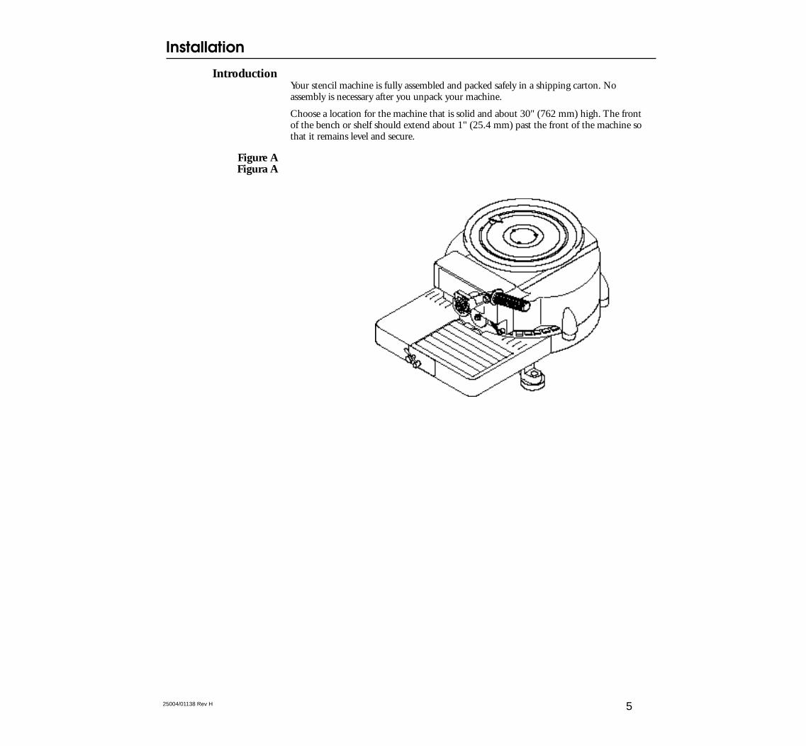
IntroductionYour stencil machine is fully assembled and packed safely in a shipping carton. Noassembly is necessary after you unpack your machine.
Choose a location for the machine that is solid and about 30" (762 mm) high. The frontof the bench or shelf should extend about 1" (25.4 mm) past the front of the machine sothat it remains level and secure.
Figure AFigura A
Inserting the StencilBoard
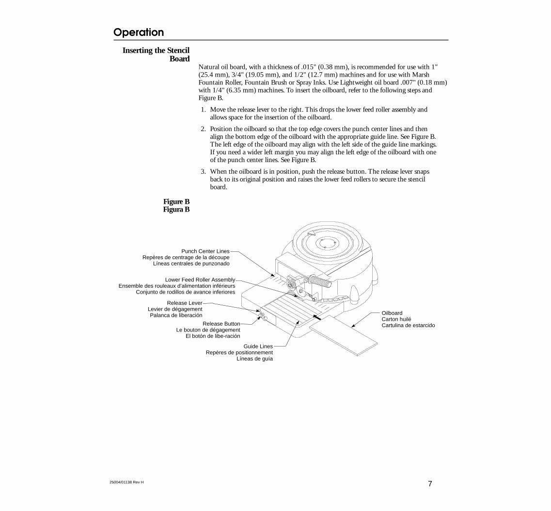
Natural oil board, with a thickness of .015" (0.38 mm), is recommended for use with 1"(25.4 mm), 3/4" (19.05 mm), and 1/2" (12.7 mm) machines and for use with MarshFountain Roller, Fountain Brush or Spray Inks. Use Lightweight oil board .007" (0.18 mm)with 1/4" (6.35 mm) machines. To insert the oilboard, refer to the following steps andFigure B.
1. Move the release lever to the right. This drops the lower feed roller assembly andallows space for the insertion of the oilboard.
2. Position the oilboard so that the top edge covers the punch center lines and thenalign the bottom edge of the oilboard with the appropriate guide line. See Figure B.The left edge of the oilboard may align with the left side of the guide line markings.If you need a wider left margin you may align the left edge of the oilboard with oneof the punch center lines. See Figure B.
3. When the oilboard is in position, push the release button. The release lever snapsback to its original position and raises the lower feed rollers to secure the stencilboard.
Figure BFigura B
Release LeverLevier de dégagementPalanca de liberación Oilboard
Carton huiléCartulina de estarcido
Guide LinesRepères de positionnement
Líneas de guía
Lower Feed Roller AssemblyEnsemble des rouleaux d’alimentation inférieurs
Conjunto de rodillos de avance inferiores
Punch Center LinesRepères de centrage de la découpe
Líneas centrales de punzonado
Release ButtonLe bouton de dégagement
El botón de libe-ración
Operation
725004/01138 Rev H
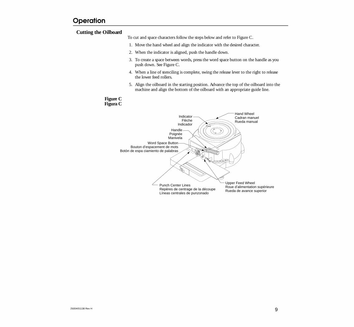
Cutting the OilboardTo cut and space characters follow the steps below and refer to Figure C.
1. Move the hand wheel and align the indicator with the desired character.
2. When the indicator is aligned, push the handle down.
3. To create a space between words, press the word space button on the handle as youpush down. See Figure C.
4. When a line of stenciling is complete, swing the release lever to the right to releasethe lower feed rollers.
5. Align the oilboard in the starting position. Advance the top of the oilboard into themachine and align the bottom of the oilboard with an appropriate guide line.
Figure CFigura C
Upper Feed WheelRoue d’alimentation supérieureRueda de avance superior
HandlePoignée
Manivela
Punch Center LinesRepères de centrage de la découpeLíneas centrales de punzonado
Word Space ButtonBouton d’espacement de mots
Botón de espa ciamiento de palabras
Hand WheelCadran manuelRueda manual
IndicatorFlèche
Indicador
Operation
925004/01138 Rev H
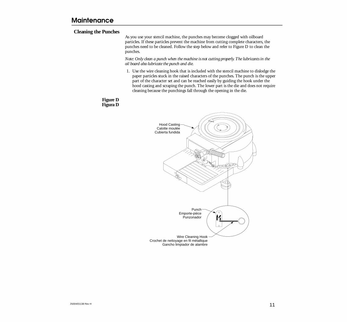
Cleaning the PunchesAs you use your stencil machine, the punches may become clogged with oilboardparticles. If these particles prevent the machine from cutting complete characters, thepunches need to be cleaned. Follow the step below and refer to Figure D to clean thepunches.
Note: Only clean a punch when the machine is not cutting properly. The lubricants in theoil board also lubricate the punch and die.
1. Use the wire cleaning hook that is included with the stencil machine to dislodge thepaper particles stuck in the raised characters of the punches. The punch is the upperpart of the character set and can be reached easily by guiding the hook under thehood casting and scraping the punch. The lower part is the die and does not requirecleaning because the punchings fall through the opening in the die.
Figure DFigura D
PunchEmporte-pièce
Punzonador
Wire Cleaning HookCrochet de nettoyage en fil métallique
Gancho limpiador de alambre
Hood CastingCalotte moulée
Cubierta fundida
Maintenance
1125004/01138 Rev H
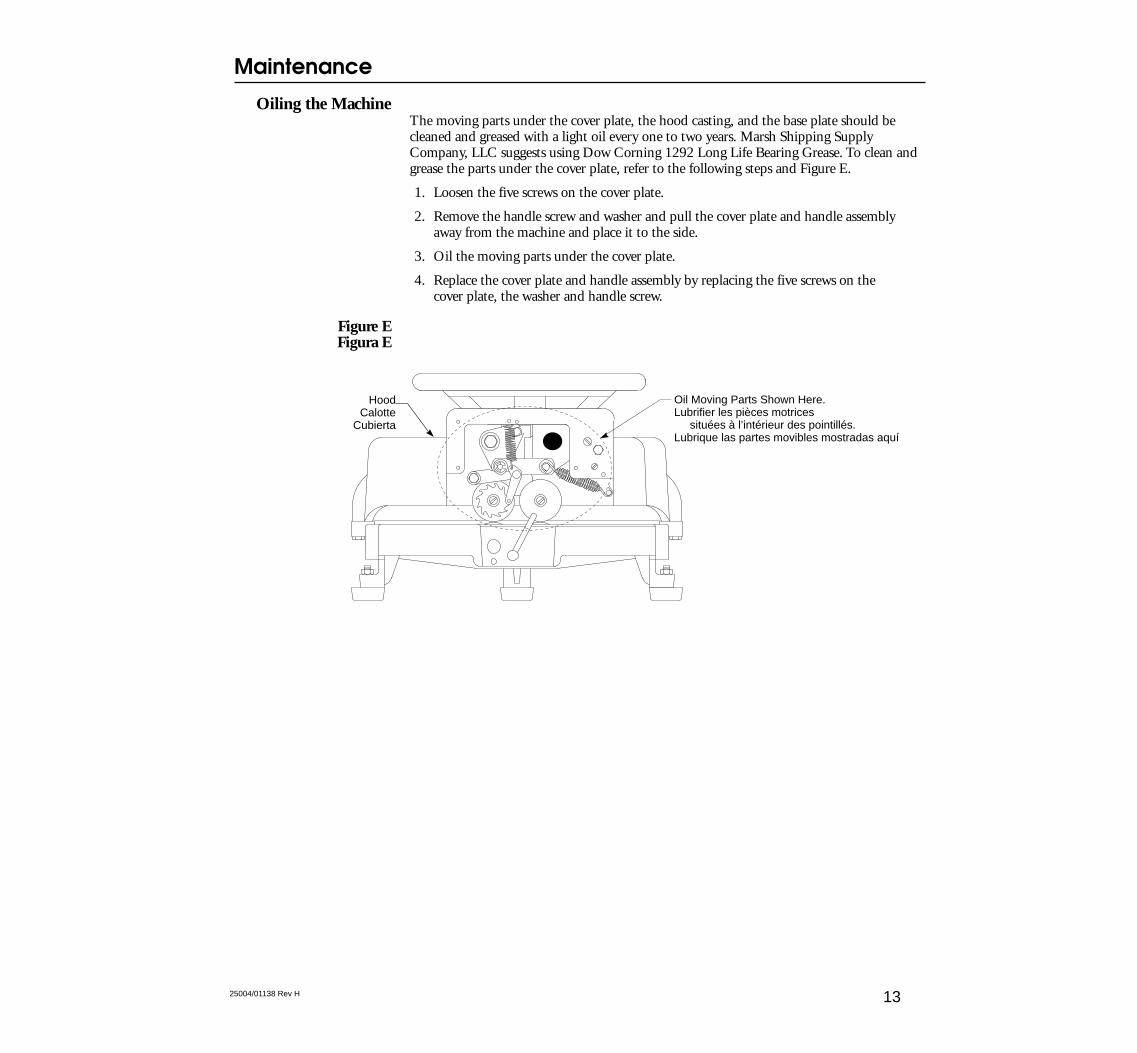
Oiling the MachineThe moving parts under the cover plate, the hood casting, and the base plate should becleaned and greased with a light oil every one to two years. Marsh Shipping SupplyCompany, LLC suggests using Dow Corning 1292 Long Life Bearing Grease. To clean andgrease the parts under the cover plate, refer to the following steps and Figure E.
1. Loosen the five screws on the cover plate.
2. Remove the handle screw and washer and pull the cover plate and handle assemblyaway from the machine and place it to the side.
3. Oil the moving parts under the cover plate.
4. Replace the cover plate and handle assembly by replacing the five screws on thecover plate, the washer and handle screw.
Figure EFigura E
Oil Moving Parts Shown Here.Lubrifier les pièces motrices situées à l’intérieur des pointillés.Lubrique las partes movibles mostradas aquí
HoodCalotte
Cubierta
Maintenance
1325004/01138 Rev H
This troubleshooting section describes potential problems that you may encounter whileworking with your hand stencil machine, outlines the possible causes for these problems,and guides you through the corrective actions. Follow the procedures outlined in theOperation and Maintenance sections of this manual to help prevent problems fromoccurring. For further assistance, please contact your Marsh distributor, or MarshShipping Supply Company, LLC at:
Technical SupportTelephone: 573.437.7030
Fax: 573.437.4030
Problem: The oilboard is moving erratically through the machine.
Possible Cause:1. There is a build up of heavy oil on the moving parts
under the cover plate.
2. The treads on the left feed wheel are dirty.
Problem: The oilboard is moving unevenly through the machine causing the characters to beslanted or crooked.
Possible Cause:1. The tracking needs to be adjusted.
Problem: The spacing between the characters is uneven.
Possible Cause:1. A build up of dirt and/or heavy oil on the left feed
wheel may be causing the oil board to slip whilemoving through the machine, thus causing erraticspacing of the characters.
2. The tension of the stud collar on the eccentric shaftcan also affect the spacing if the tension is too tightor too loose.
Troubleshooting
14 25004/01138 Rev H
Solution:1. Be sure the machine is properly oiled and cleaned
every one to two years. See page 13 for informationon oiling the parts under the cover plate.
2. Clean the treads on the left feed wheel with a wirebrush. See page 21.
Solution:1. Adjust the tracking on the lower feed roller
assembly. See page 23.
Solution:1. Clean the treads on the left feed wheel with a wire
brush. See page 21.
2. Be sure the tension of the stud collar is set correctlyby following steps 1 through 3 and 9 through 12 onpage 29 and 31.
Problem: The punches are not cutting completely through the oilboard.
Possible Cause:1. The punches are clogged with oilboard particles.
2. The punch depth adjustment may need to beincreased.
3. If cleaning the punches with the cleaning hook andadjusting the punch depth does not improve thecutting of the characters, the punch and die need tobe replaced.
Problem: The lower feed rollers are not griping the oilboard.
Possible Cause: 1. The left lower feed roller is catching or not moving
smoothly because of wear.
Solution:1. Clean the punches with the cleaning hook. See page
11.
2. The punch depth adjustment is preset at the factory.Only adjust the punch depth if the punches are notcutting properly after being cleaned with thecleaning hook. To adjust the punch depth, see page25.
3. Replace the punch and die that is not cuttingproperly. See page 27.
Solution:1. Replace the lower feed roller assembly. See page 29.
Troubleshooting
1525004/01138 Rev H
This section provides steps that guide you through the repair or replacement of certainparts.
Cleaning the Treadson the Left Feed
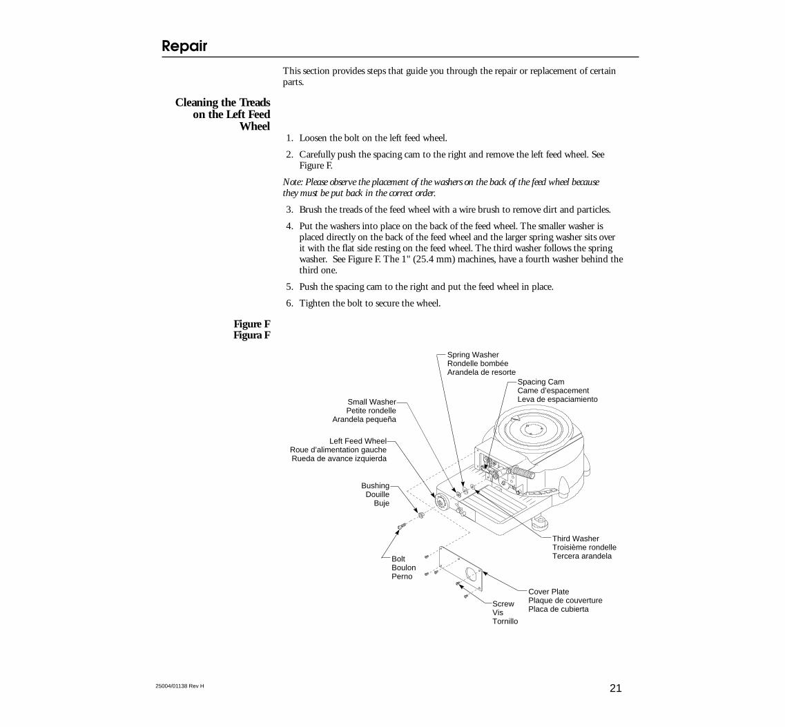
Wheel1. Loosen the bolt on the left feed wheel.
2. Carefully push the spacing cam to the right and remove the left feed wheel. SeeFigure F.
Note: Please observe the placement of the washers on the back of the feed wheel becausethey must be put back in the correct order.
3. Brush the treads of the feed wheel with a wire brush to remove dirt and particles.
4. Put the washers into place on the back of the feed wheel. The smaller washer isplaced directly on the back of the feed wheel and the larger spring washer sits overit with the flat side resting on the feed wheel. The third washer follows the springwasher. See Figure F. The 1" (25.4 mm) machines, have a fourth washer behind thethird one.
5. Push the spacing cam to the right and put the feed wheel in place.
6. Tighten the bolt to secure the wheel.
Figure FFigura F
ScrewVisTornillo
Cover PlatePlaque de couverturePlaca de cubierta
BoltBoulonPerno
Left Feed WheelRoue d’alimentation gaucheRueda de avance izquierda
Small WasherPetite rondelle
Arandela pequeña
Spring WasherRondelle bombéeArandela de resorte
Spacing CamCame d’espacementLeva de espaciamiento
Third WasherTroisième rondelleTercera arandela
BushingDouille
Buje
Repair
2125004/01138 Rev H
Repair
2325004/01138 Rev H
Adjusting theTracking on the LowerFeed Roller Assembly
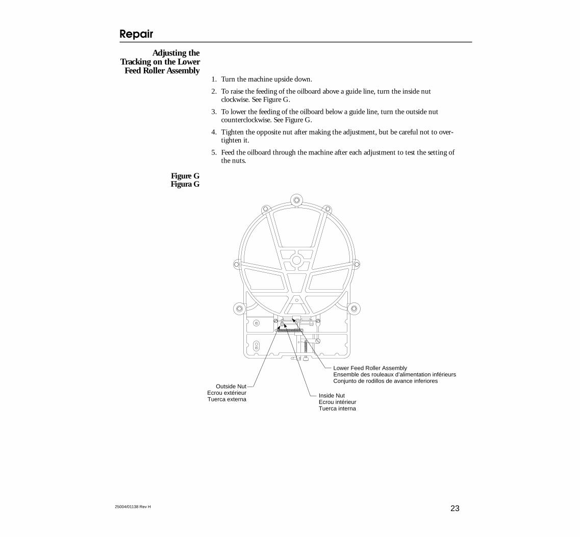
1. Turn the machine upside down.
2. To raise the feeding of the oilboard above a guide line, turn the inside nutclockwise. See Figure G.
3. To lower the feeding of the oilboard below a guide line, turn the outside nutcounterclockwise. See Figure G.
4. Tighten the opposite nut after making the adjustment, but be careful not to over-tighten it.
5. Feed the oilboard through the machine after each adjustment to test the setting ofthe nuts.
Figure GFigura G
Lower Feed Roller AssemblyEnsemble des rouleaux d’alimentation inférieursConjunto de rodillos de avance inferiores
Outside NutEcrou extérieurTuerca externa
Inside NutEcrou intérieurTuerca interna
Adjusting the PunchDepth
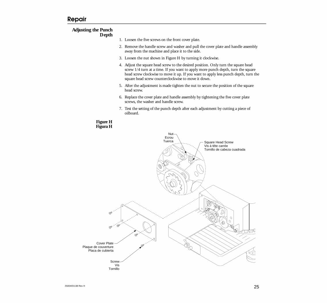
1. Loosen the five screws on the front cover plate.
2. Remove the handle screw and washer and pull the cover plate and handle assemblyaway from the machine and place it to the side.
3. Loosen the nut shown in Figure H by turning it clockwise.
4. Adjust the square head screw to the desired position. Only turn the square headscrew 1/4 turn at a time. If you want to apply more punch depth, turn the squarehead screw clockwise to move it up. If you want to apply less punch depth, turn thesquare head screw counterclockwise to move it down.
5. After the adjustment is made tighten the nut to secure the position of the squarehead screw.
6. Replace the cover plate and handle assembly by tightening the five cover platescrews, the washer and handle screw.
7. Test the setting of the punch depth after each adjustment by cutting a piece ofoilboard.
Figure HFigura H
NutEcrou
Tuerca Square Head ScrewVis à tête carréeTornillo de cabeza cuadrada
ScrewVis
Tornillo
Cover PlatePlaque de couverture
Placa de cubierta
Repair
2525004/01138 Rev H
Replacing a Punchand Die
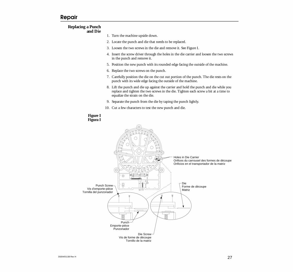
1. Turn the machine upside down.
2. Locate the punch and die that needs to be replaced.
3. Loosen the two screws in the die and remove it. See Figure I.
4. Insert the screw driver through the holes in the die carrier and loosen the two screwsin the punch and remove it.
5. Position the new punch with its rounded edge facing the outside of the machine.
6. Replace the two screws on the punch.
7. Carefully position the die on the cut out portion of the punch. The die rests on thepunch with its wide edge facing the outside of the machine.
8. Lift the punch and die up against the carrier and hold the punch and die while youreplace and tighten the two screws in the die. Tighten each screw a bit at a time toequalize the strain on the die.
9. Separate the punch from the die by taping the punch lightly.
10. Cut a few characters to test the new punch and die.
Figure IFigura I
DieForme de découpeMatriz
Holes in Die CarrierOrifices du carrousel des formes de découpeOrificios en el transportador de la matriz
Die ScrewVis de forme de découpe
Tornillo de la matriz
PunchEmporte-pièce
Punzonador
Punch ScrewVis d’emporte-pièce
Tornilla del punzonador
Repair
2725004/01138 Rev H
Replacing the LowerFeed Roller Assembly
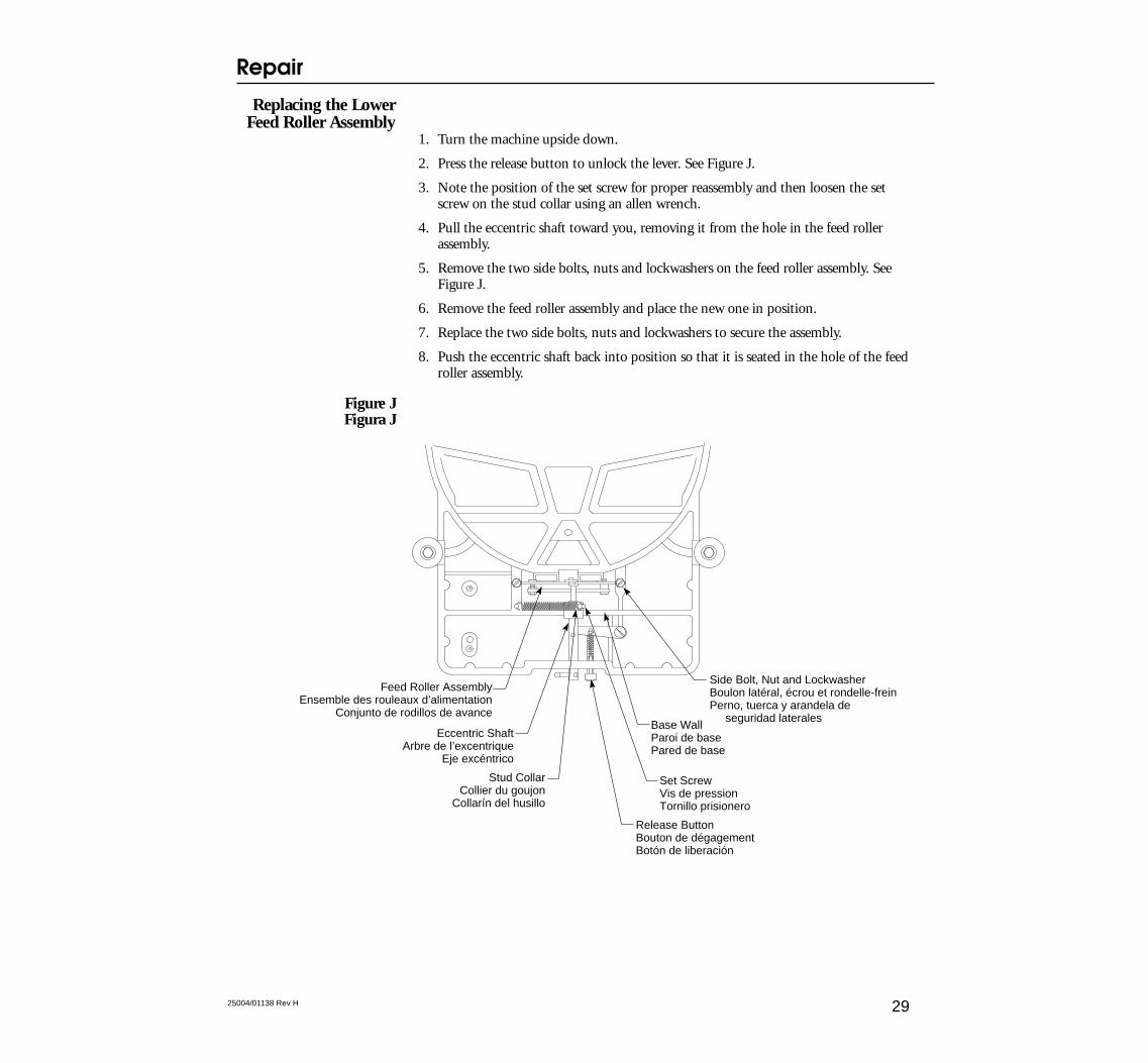
1. Turn the machine upside down.
2. Press the release button to unlock the lever. See Figure J.
3. Note the position of the set screw for proper reassembly and then loosen the setscrew on the stud collar using an allen wrench.
4. Pull the eccentric shaft toward you, removing it from the hole in the feed rollerassembly.
5. Remove the two side bolts, nuts and lockwashers on the feed roller assembly. SeeFigure J.
6. Remove the feed roller assembly and place the new one in position.
7. Replace the two side bolts, nuts and lockwashers to secure the assembly.
8. Push the eccentric shaft back into position so that it is seated in the hole of the feedroller assembly.
Figure JFigura J
Release ButtonBouton de dégagementBotón de liberación
Set ScrewVis de pressionTornillo prisionero
Side Bolt, Nut and LockwasherBoulon latéral, écrou et rondelle-freinPerno, tuerca y arandela de seguridad laterales
Stud CollarCollier du goujon
Collarín del husillo
Eccentric ShaftArbre de l’excentrique
Eje excéntrico
Feed Roller AssemblyEnsemble des rouleaux d’alimentation
Conjunto de rodillos de avanceBase WallParoi de basePared de base
Repair
2925004/01138 Rev H
9. Place the stud collar about 1/16" (1.6 mm) from the base wall, but not so close thatit rubs against the wall.
10. Insert the allen wrench in the set screw of the stud collar and pull the stud collar andspring to the right. Make sure the eccentric shaft remains inserted in the hole of thefeed roller assembly and the collar is flush with the base wall closest to you.
11. When these parts are in position and the tension on the spring is as it is shown inFigure J, tighten the set screw to its original position.
12. Test the play of the eccentric shaft and stud collar by gently pulling on the studcollar. Some movement should be allowed.
Repair
3125004/01138 Rev H
Parts List Liste des pi ces de rechange Lista de repuestos
33
1
456
3 2
1
3
2
4
5
9
10
6
7
8
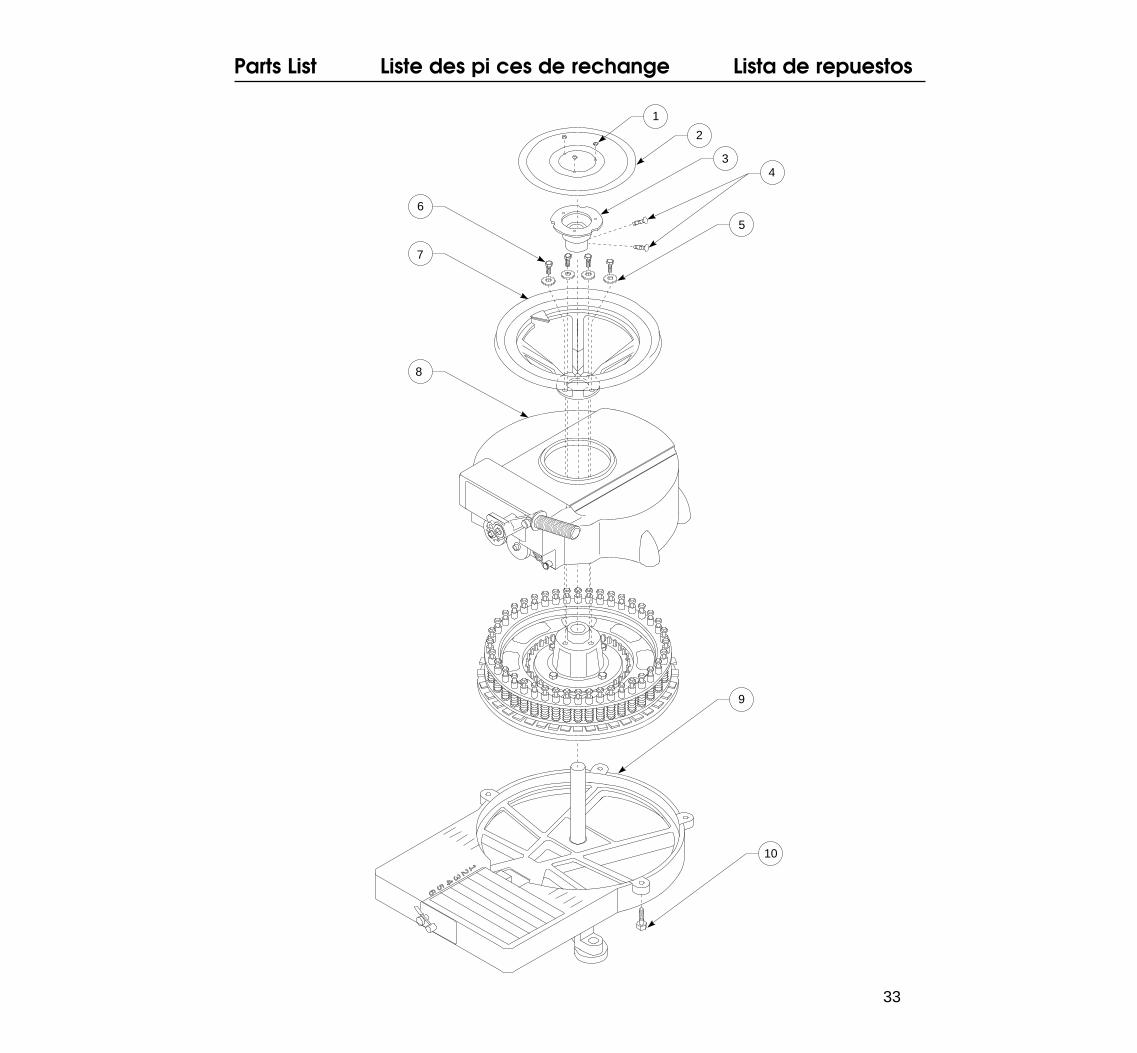
Front AssemblySee page 40 for item descriptions and orders numbers.
Ensemble avantVoir la page 44 pour la description et le numéro de chaque pièce.
Ensamblaje de la partefrontal
Véase la página 48 para obtener las descripciones y el número pedido de las piezas.
Parts List Liste des pi ces de rechange Lista de repuestos
34 25004/01138 Rev H
Parts List Liste des pi ces de rechange Lista de repuestos
3525004/01138 Rev H
16
1
9
5
11
5
12
6
2
3
87
14
15
16
17
20
1918
21
24
25
26
27
28
48
35
3433
29
30
3132
37
38
39
4041
1142
43
44
45
46
47
1321
18
22
23
3610
4
16
49
Parts List Liste des pi ces de rechange Lista de repuestos
36 25004/01138 Rev H
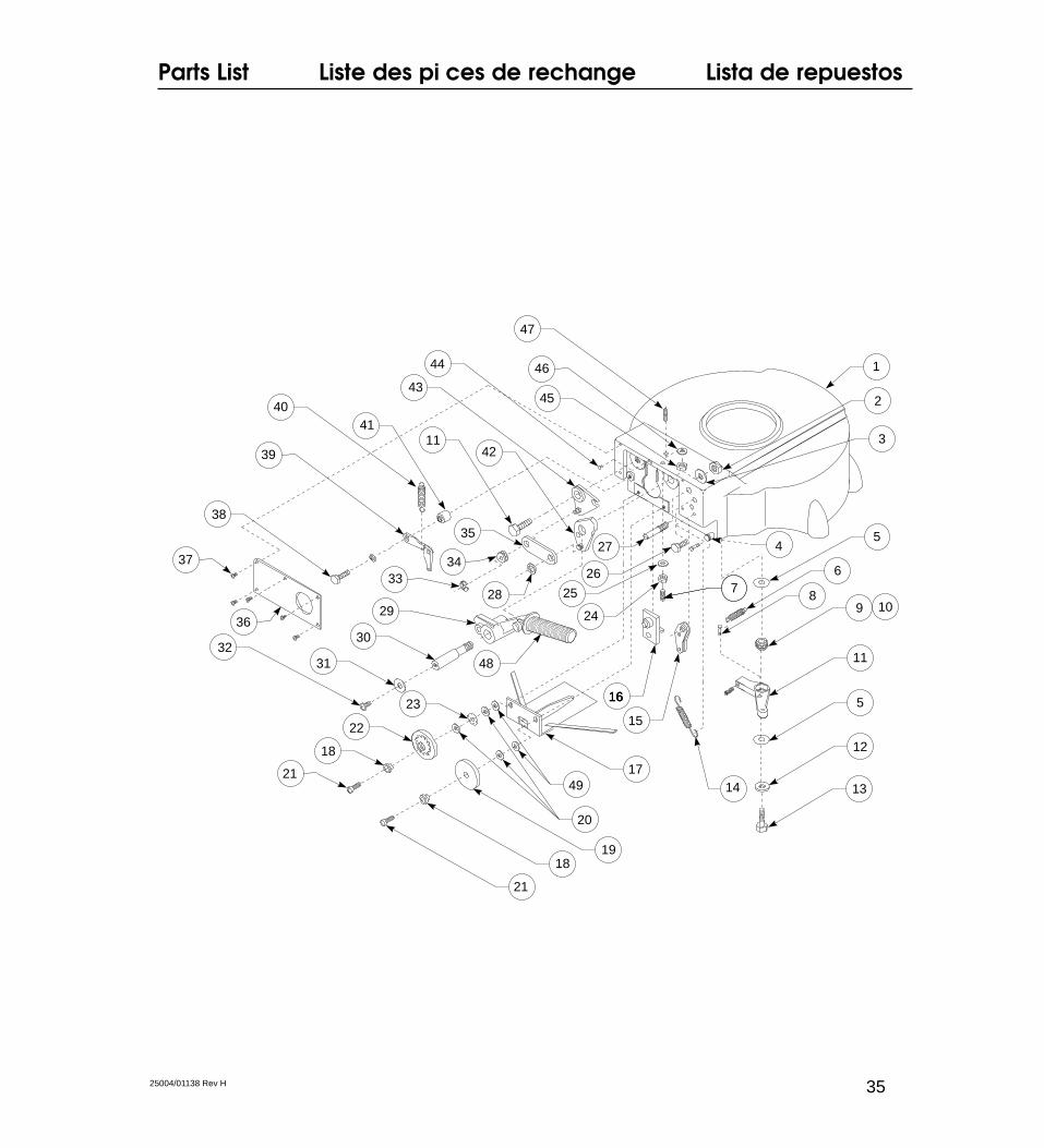
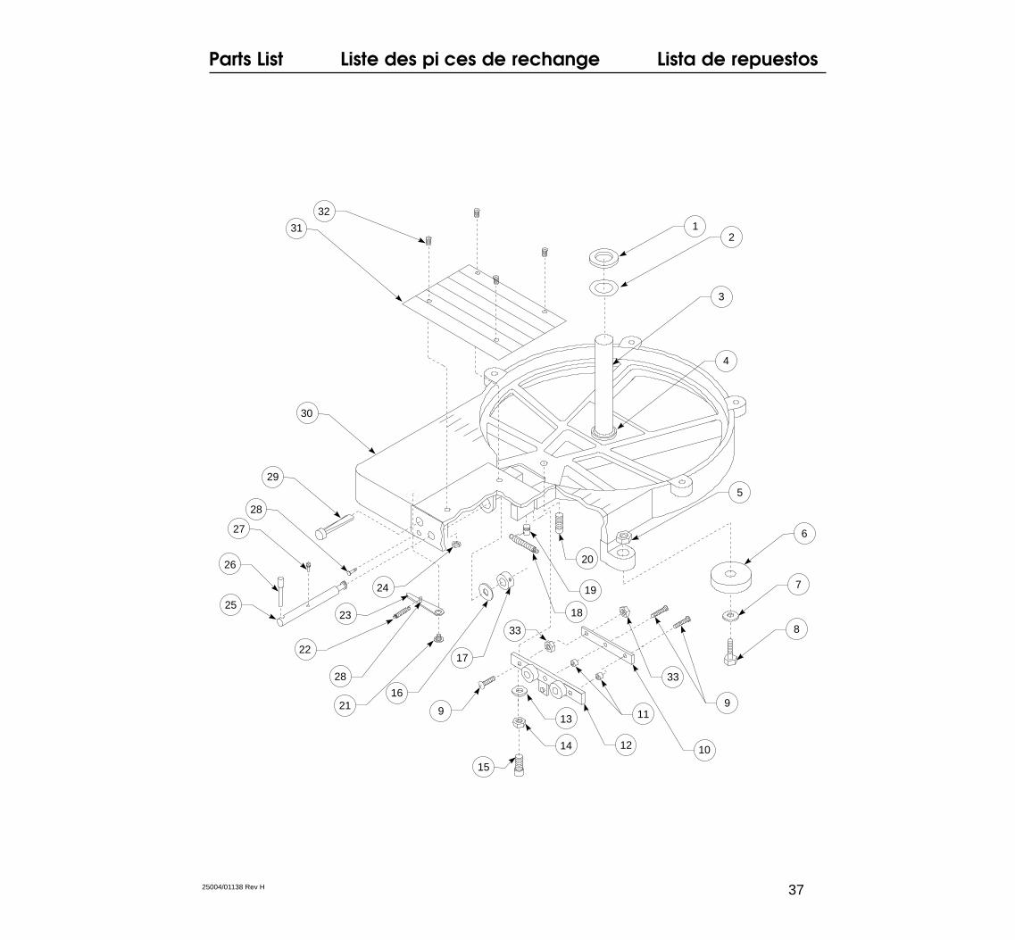
Base AssemblySee page 42 for item descriptions and orders numbers.
Ensemble baseVoir la page 46 pour la description et le numéro de chaque pièce.
Ensamblaje de la baseVéase la página 50 para obtener las descripciones y el número pedido de las piezas.
Parts List Liste des pi ces de rechange Lista de repuestos
3725004/01138 Rev H
12
3
4
6
7
8
5
9
10
11
12
13
14
18
15
19
20
16
17
21
22
23
24
25
26
27
28
28
29
30
31
32
9
33
33

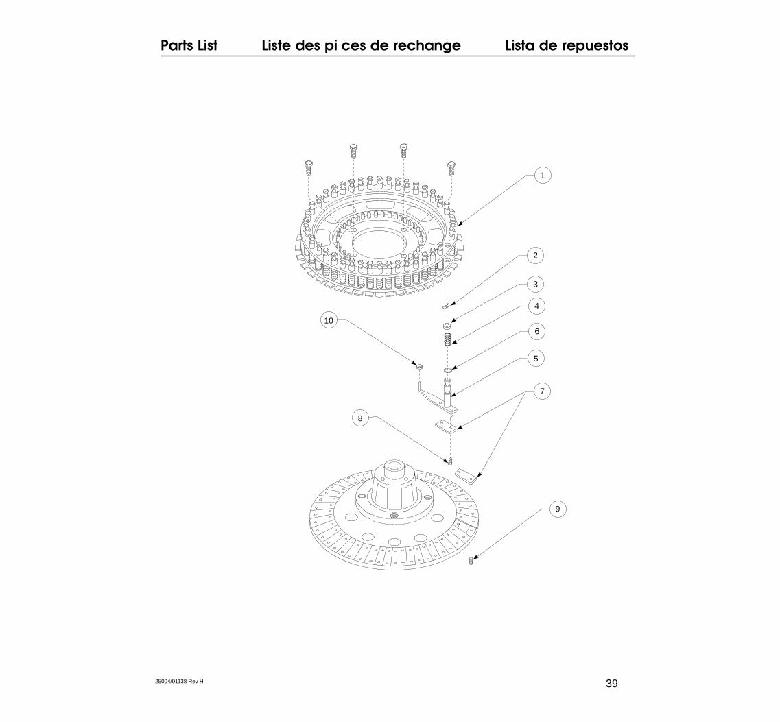
Carriage AssemblySee page 43 for item descriptions and orders numbers.
Ensemble de carrouselVoir la page 47 pour la description et le numéro de chaque pièce.
Conjunto detransportación
Véase la página 51 para obtener las descripciones y el número pedido de las piezas.
Parts List Liste des pi ces de rechange Lista de repuestos
38 25004/01138 Rev H
Parts List Liste des pi ces de rechange Lista de repuestos
3925004/01138 Rev H
1
5
4
2
3
7
9
10
8
6

Parts List
40
The following pages show the Hand Stencil Machine and the corresponding numbers forrepair parts. Please order your replacement parts by requesting the part number shown.Please also note the quantity provided in each package and the specific part numbernecessary for your machine.
Stencil MachineAssembly,
see page 33Description Part Number Quantity per kit
1. Screw, phillips truss head RP32A 52. Dial blank, manual RP32 13. Holder, dial RP08 14. Screw, set square head RP08B 55. Washer RP1503C 56. Screw,cap head hex RP04A 57. Wheel assy, hand RP07X 18. Hood (1/4", 1/2", 3/4") RP02-SHQ 1
Hood (1") RP02-R 19. Base, with shaft and plate 1/2" RP01X-H 1
Base, with shaft and plate 3/4" RP01X-S 1Base, with center shaft 1" RP01X-R 1Base, with shaft and plate 1/4" RP01X-Q 1
10. Cap, hex head (1/4", 1/2", 3/4") RP01A-SHQ 5Cap, hex head (1") RP01A-R 5
Front Assembly, see page 35
Description Part Number Quantity per kit
1. Hood (1/4", 1/2", 3/4") RP02-SHQ 1Hood (1") RP02-R 1
2. Nut, hex RP22A 53. Washer, lock internal tooth RP22B 54. Stud, spring RP37 15. Washer RP35SW 56. Spring, centering arm RP30S 27. Screw, set square head RP47 58. Pin, release button RP18B 19. Arm liner, assy centering RP35A 1
10. O-ring RP35B 511. Arm assy, centering (1/4", 1/2", 3/4") RP30X-SHQ 1
Arm assy, centering (1") RP30X-R 112. Washer RP35W 513. Screw, cap hex head RP09A 514. Spring, handle RP37S 115. Rocker assy, centering RP28 116. Plunger assy RP31 1
Parts List
41
Front Assembly, see page 35(continued)
Description Part Number Quantity per kit
17. Stripper assy (1/4", 1/2", 3/4", 1") RP33 118. Bushing, feed wheel RP23A 419. Wheel, feed right RP23R 520. Washer, feed wheel RP23W 521. Screw, slot flat head RP38 522. Wheel assy, feed left (1/4") RP23LB-Q 1
Wheel assy, feed left (1/2") RP23LB-H 1Wheel assy, feed left (3/4") RP23LB-S 1Wheel assy, feed left (1") RP23LB-R 1
23. Washer, sprag spring RP1611-AR 524. Nut RP47A 125. Washer, lock integral tooth RP47B 126. Stop, spacing RP44 227. Stud, centering rocker RP29 128. Washer, link pin right RP13A 529. Handle, assy operating (1/4", 1/2", 3/4") RP20X-SHQ 1
Handle, assy operating (1" ) RP20X-R 130. Shaft, handle RP22 131. Washer RP21 532. Screw, phillips pan head RP06C-R 533. Ring, lock RP3157 534. Follower, spacing cam RP24 235. Link (1/4", 1/2", 3/4") RP12- SHQ 1
Link (1" machine) RP12-R 136. Cover plate, front RP43 137. Screw, phillips pan head RP43A 538. Screw, cap hex head RP36B 539. Cam assy, spacing (1/4") RP25-Q 1
Cam assy, spacing (1/2") RP25-H 1Cam assy, spacing (3/4") RP25-S 1Cam assy, spacing (1") RP25-R 1
40. Spring, spacing finger RP25S 241. Bushing, spacing cam RP36 242. Cam assy, centering RP10 143. Rocker assy RP14 144. Stud, spring spacing RP25E 545. Nut, hex jam RP47A 546. Washer, lock integral tooth RP47B 547. Screw, set (1/4", 1/2", 3/4") RP48-SHQ 5
Screw, set (1") RP48-R 548. Grip, Handle 7/8" Flangeless RP27944 149. Washer RPTC19 5
Parts List
42
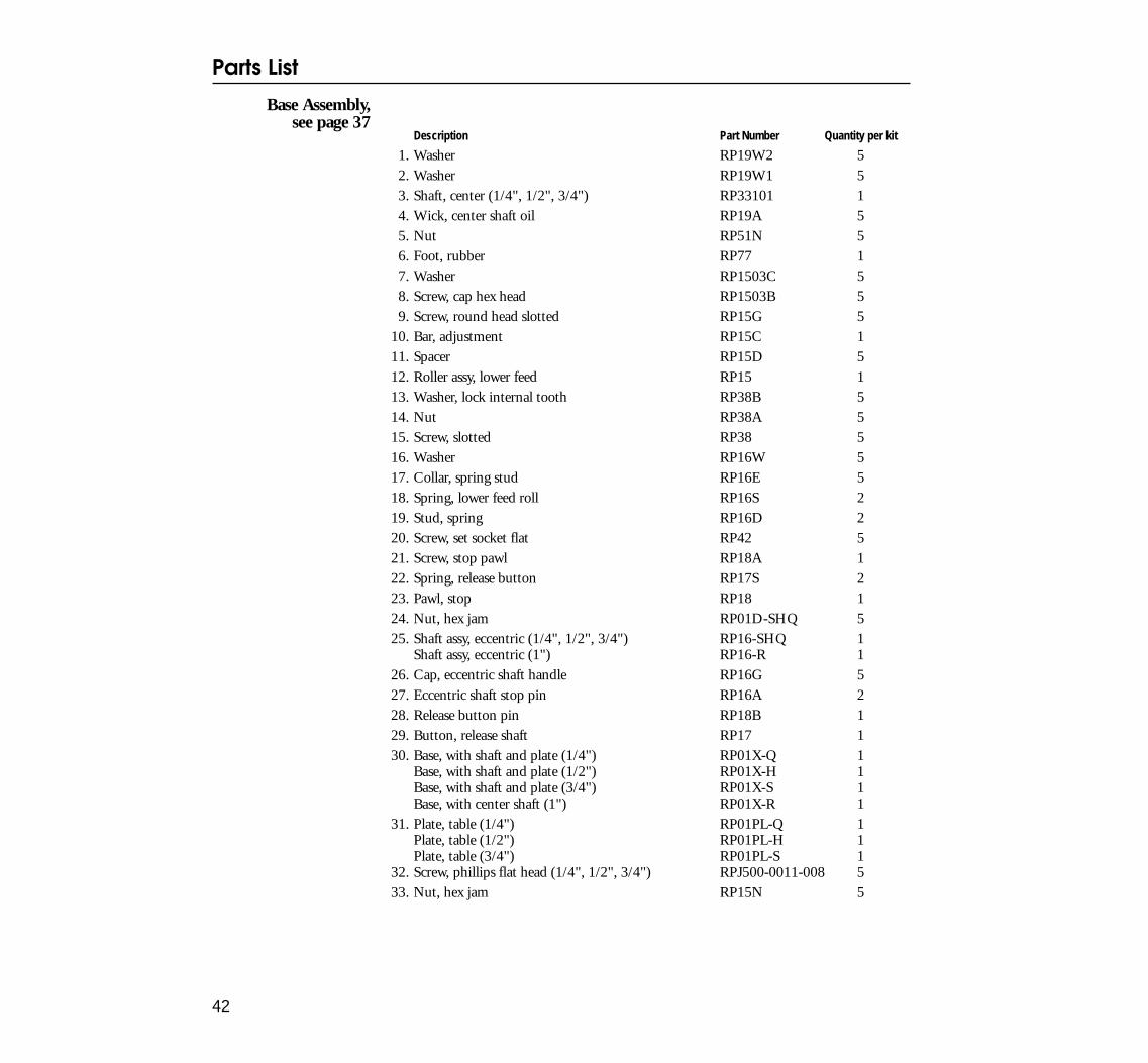
Base Assembly,see page 37
Description Part Number Quantity per kit
1. Washer RP19W2 52. Washer RP19W1 53. Shaft, center (1/4", 1/2", 3/4") RP33101 14. Wick, center shaft oil RP19A 55. Nut RP51N 56. Foot, rubber RP77 17. Washer RP1503C 58. Screw, cap hex head RP1503B 59. Screw, round head slotted RP15G 5
10. Bar, adjustment RP15C 111. Spacer RP15D 512. Roller assy, lower feed RP15 113. Washer, lock internal tooth RP38B 514. Nut RP38A 515. Screw, slotted RP38 516. Washer RP16W 517. Collar, spring stud RP16E 518. Spring, lower feed roll RP16S 219. Stud, spring RP16D 220. Screw, set socket flat RP42 521. Screw, stop pawl RP18A 122. Spring, release button RP17S 223. Pawl, stop RP18 124. Nut, hex jam RP01D-SHQ 525. Shaft assy, eccentric (1/4", 1/2", 3/4") RP16-SHQ 1
Shaft assy, eccentric (1") RP16-R 126. Cap, eccentric shaft handle RP16G 527. Eccentric shaft stop pin RP16A 228. Release button pin RP18B 129. Button, release shaft RP17 130. Base, with shaft and plate (1/4") RP01X-Q 1
Base, with shaft and plate (1/2") RP01X-H 1Base, with shaft and plate (3/4") RP01X-S 1Base, with center shaft (1") RP01X-R 1
31. Plate, table (1/4") RP01PL-Q 1Plate, table (1/2") RP01PL-H 1Plate, table (3/4") RP01PL-S 1
32. Screw, phillips flat head (1/4", 1/2", 3/4") RPJ500-0011-008 533. Nut, hex jam RP15N 5
Parts List
43
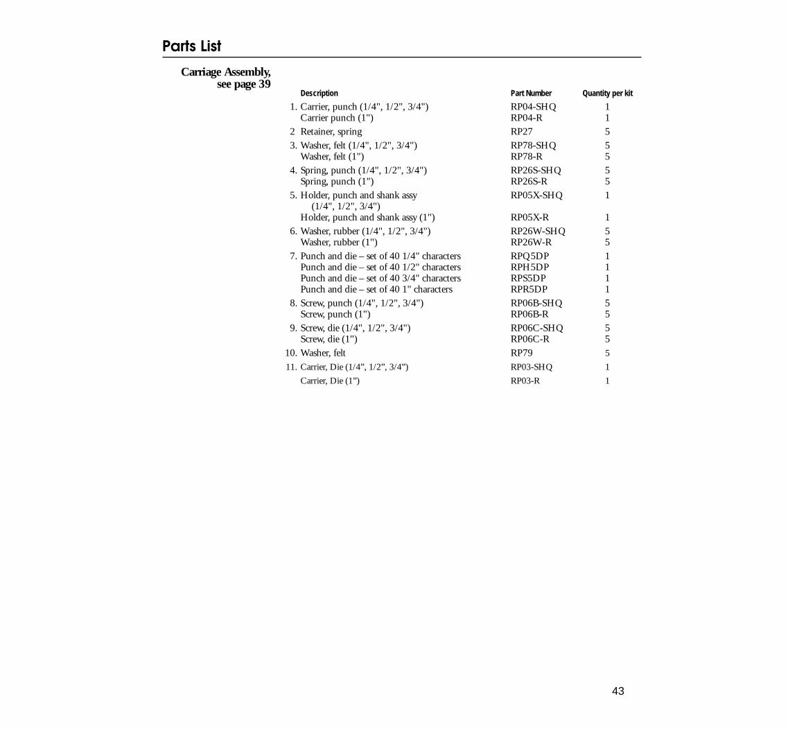
Carriage Assembly,see page 39
Description Part Number Quantity per kit
1. Carrier, punch (1/4", 1/2", 3/4") RP04-SHQ 1Carrier punch (1") RP04-R 1
2 Retainer, spring RP27 53. Washer, felt (1/4", 1/2", 3/4") RP78-SHQ 5
Washer, felt (1") RP78-R 54. Spring, punch (1/4", 1/2", 3/4") RP26S-SHQ 5
Spring, punch (1") RP26S-R 55. Holder, punch and shank assy RP05X-SHQ 1
(1/4", 1/2", 3/4")Holder, punch and shank assy (1") RP05X-R 1
6. Washer, rubber (1/4", 1/2", 3/4") RP26W-SHQ 5Washer, rubber (1") RP26W-R 5
7. Punch and die – set of 40 1/4" characters RPQ5DP 1Punch and die – set of 40 1/2" characters RPH5DP 1Punch and die – set of 40 3/4" characters RPS5DP 1Punch and die – set of 40 1" characters RPR5DP 1
8. Screw, punch (1/4", 1/2", 3/4") RP06B-SHQ 5Screw, punch (1") RP06B-R 5
9. Screw, die (1/4", 1/2", 3/4") RP06C-SHQ 5Screw, die (1") RP06C-R 5
10. Washer, felt RP79 5
11. Carrier, Die (1/4”, 1/2”, 3/4”) RP03-SHQ 1
Carrier, Die (1”) RP03-R 1
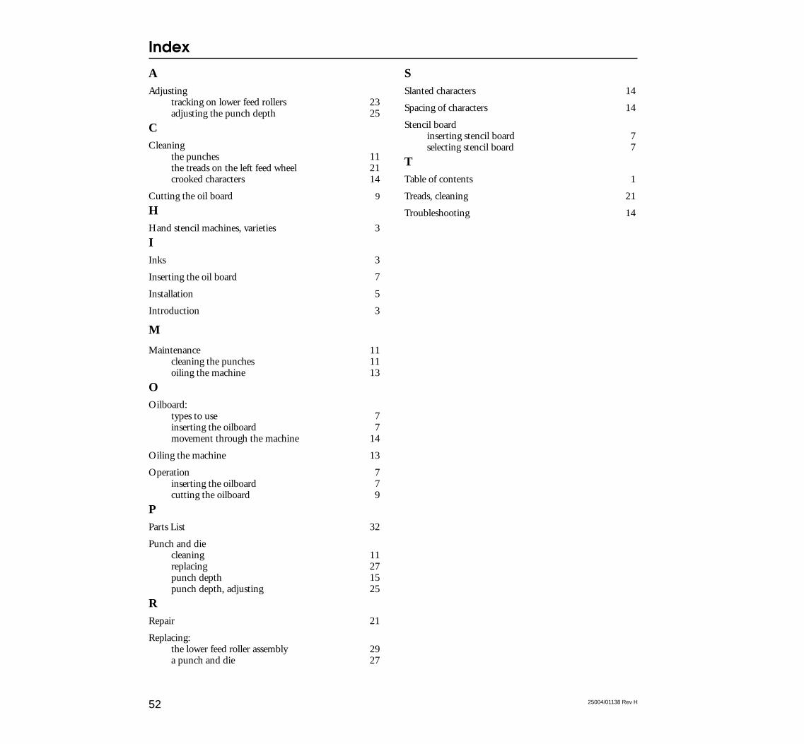
Index
52 25004/01138 Rev H
AAdjusting
tracking on lower feed rollers 23adjusting the punch depth 25
CCleaning
the punches 11the treads on the left feed wheel 21crooked characters 14
Cutting the oil board 9
HHand stencil machines, varieties 3
IInks 3
Inserting the oil board 7
Installation 5
Introduction 3
M
Maintenance 11cleaning the punches 11oiling the machine 13
OOilboard:
types to use 7inserting the oilboard 7movement through the machine 14
Oiling the machine 13
Operation 7inserting the oilboard 7cutting the oilboard 9
PParts List 32
Punch and diecleaning 11replacing 27punch depth 15punch depth, adjusting 25
RRepair 21
Replacing:the lower feed roller assembly 29a punch and die 27
SSlanted characters 14
Spacing of characters 14
Stencil boardinserting stencil board 7selecting stencil board 7
TTable of contents 1
Treads, cleaning 21
Troubleshooting 14


![POCHOIRS Quelques exemples. POCHOIRS Définition : Pochoir : nom masculin Sens : Plaque découpée permettant de dessiner la forme évidée [Peinture]. Synonyme.](https://static.fdocuments.fr/doc/165x107/551d9ddc497959293b8e8a94/pochoirs-quelques-exemples-pochoirs-definition-pochoir-nom-masculin-sens-plaque-decoupee-permettant-de-dessiner-la-forme-evidee-peinture-synonyme.jpg)