Geometrical product specifications (GPS) — Dimensional ... · ISO 10579, Geometrical product...
30
© ISO 2015 Geometrical product specifications (GPS) — Dimensional and geometrical tolerances for moulded parts — Part 4: General tolerances for castings using profile tolerancing in a general datum system Spécification géométrique des produits (GPS) — Tolérances dimensionnelles et géométriques des pièces moulées — Partie 4: Tolérances générales pour les moules (selon les règles GPS) ICS: 17.040.10 Reference number ISO/DIS 8062-4.2:2015(E) DRAFT INTERNATIONAL STANDARD ISO/DIS 8062-4.2 ISO/TC 213 Secretariat: DS Voting begins on: Voting terminates on: 2015-07-21 2015-09-21 THIS DOCUMENT IS A DRAFT CIRCULATED FOR COMMENT AND APPROVAL. IT IS THEREFORE SUBJECT TO CHANGE AND MAY NOT BE REFERRED TO AS AN INTERNATIONAL STANDARD UNTIL PUBLISHED AS SUCH. IN ADDITION TO THEIR EVALUATION AS BEING ACCEPTABLE FOR INDUSTRIAL, TECHNOLOGICAL, COMMERCIAL AND USER PURPOSES, DRAFT INTERNATIONAL STANDARDS MAY ON OCCASION HAVE TO BE CONSIDERED IN THE LIGHT OF THEIR POTENTIAL TO BECOME STANDARDS TO WHICH REFERENCE MAY BE MADE IN NATIONAL REGULATIONS. RECIPIENTS OF THIS DRAFT ARE INVITED TO SUBMIT, WITH THEIR COMMENTS, NOTIFICATION OF ANY RELEVANT PATENT RIGHTS OF WHICH THEY ARE AWARE AND TO PROVIDE SUPPORTING DOCUMENTATION.
Transcript of Geometrical product specifications (GPS) — Dimensional ... · ISO 10579, Geometrical product...

© ISO 2015
Geometrical product specifications (GPS) — Dimensional and geometrical tolerances for moulded parts —Part 4: General tolerances for castings using profile tolerancing in a general datum systemSpécification géométrique des produits (GPS) — Tolérances dimensionnelles et géométriques des pièces moulées —Partie 4: Tolérances générales pour les moules (selon les règles GPS)
ICS: 17.040.10
Reference number ISO/DIS 8062-4.2:2015(E)
DRAFT INTERNATIONAL STANDARD ISO/DIS 8062-4.2
ISO/TC 213 Secretariat: DS
Voting begins on: Voting terminates on:2015-07-21 2015-09-21
THIS DOCUMENT IS A DRAFT CIRCULATED FOR COMMENT AND APPROVAL. IT IS THEREFORE SUBJECT TO CHANGE AND MAY NOT BE REFERRED TO AS AN INTERNATIONAL STANDARD UNTIL PUBLISHED AS SUCH.
IN ADDITION TO THEIR EVALUATION AS BEING ACCEPTABLE FOR INDUSTRIAL, TECHNOLOGICAL, COMMERCIAL AND USER PURPOSES, DRAFT INTERNATIONAL STANDARDS MAY ON OCCASION HAVE TO BE CONSIDERED IN THE LIGHT OF THEIR POTENTIAL TO BECOME STANDARDS TO WHICH REFERENCE MAY BE MADE IN NATIONAL REGULATIONS.
RECIPIENTS OF THIS DRAFT ARE INVITED TO SUBMIT, WITH THEIR COMMENTS, NOTIFICATION OF ANY RELEVANT PATENT RIGHTS OF WHICH THEY ARE AWARE AND TO PROVIDE SUPPORTING DOCUMENTATION.
ISO/DIS 8062-4.2:2015(E)
ii © ISO 2015 – All rights reserved
COPYRIGHT PROTECTED DOCUMENT
© ISO 2015, Published in SwitzerlandAll rights reserved. Unless otherwise specified, no part of this publication may be reproduced or utilized otherwise in any form or by any means, electronic or mechanical, including photocopying, or posting on the internet or an intranet, without prior written permission. Permission can be requested from either ISO at the address below or ISO’s member body in the country of the requester.
ISO copyright officeCh. de Blandonnet 8 • CP 401CH-1214 Vernier, Geneva, SwitzerlandTel. +41 22 749 01 11Fax +41 22 749 09 [email protected]
ISO/DIS 8062-4.2:2015(E)
Foreword ........................................................................................................................................................................................................................................ivIntroduction ..................................................................................................................................................................................................................................v1 Scope ................................................................................................................................................................................................................................. 12 Normative references ...................................................................................................................................................................................... 13 Terms and definitions ..................................................................................................................................................................................... 14 Rules .................................................................................................................................................................................................................................. 2
4.1 Rule A: Application of general tolerances for castings ......................................................................................... 24.2 Rule B: General profile surface tolerances ...................................................................................................................... 34.3 Rule C: General datum system ................................................................................................................................................... 34.4 Rule D: Tolerances overruling the general profile surface tolerances .................................................... 34.5 Rule E: Additional tolerances ..................................................................................................................................................... 44.6 Rule F: Machined condition (application case c) ....................................................................................................... 44.7 Rule G: Required machining allowances (RMA) ......................................................................................................... 44.8 Rule H: Taper ............................................................................................................................................................................................ 4
5 General tolerances .............................................................................................................................................................................................. 56 Required machining allowances .......................................................................................................................................................... 77 Draft angles (taper) ........................................................................................................................................................................................... 78 General drawing indication ....................................................................................................................................................................10Annex A (informative) Concept of the general tolerancing ........................................................................................................12Annex B (informative) Selection of general tolerances ..................................................................................................................14Annex C (informative) Selection of required machining allowances (RMA) ............................................................15Annex D (informative) Example of using general tolerances ...................................................................................................16Annex E (informative) Calculation of the nominal dimension of the moulded condition .........................19Annex F (informative) Relation to the GPS matrix model ............................................................................................................22Bibliography .............................................................................................................................................................................................................................23
© ISO 2015 – All rights reserved iii
Contents Page

Foreword
ISO (the International Organization for Standardization) is a worldwide federation of national standards bodies (ISO member bodies). The work of preparing International Standards is normally carried out through ISO technical committees. Each member body interested in a subject for which a technical committee has been established has the right to be represented on that committee. International organizations, governmental and non-governmental, in liaison with ISO, also take part in the work. ISO collaborates closely with the International Electrotechnical Commission (IEC) on all matters of electrotechnical standardization.
The procedures used to develop this document and those intended for its further maintenance are described in the ISO/IEC Directives, Part 1. In particular the different approval criteria needed for the different types of ISO documents should be noted. This document was drafted in accordance with the editorial rules of the ISO/IEC Directives, Part 2 (see www.iso.org/directives).
Attention is drawn to the possibility that some of the elements of this document may be the subject of patent rights. ISO shall not be held responsible for identifying any or all such patent rights. Details of any patent rights identified during the development of the document will be in the Introduction and/or on the ISO list of patent declarations received (see www.iso.org/patents).
Any trade name used in this document is information given for the convenience of users and does not constitute an endorsement.
For an explanation on the meaning of ISO specific terms and expressions related to conformity assessment, as well as information about ISO’s adherence to the WTO principles in the Technical Barriers to Trade (TBT) see the following URL: Foreword - Supplementary information
The committee responsible for this document is ISO/TC 213, Dimensional and geometrical product specifications and verification.
ISO 8062 consists of the following parts, under the general title Geometrical product specifications (GPS) — Dimensional and geometrical tolerances for moulded parts:
— Part 1: Vocabulary
— Part 2: Drawing indications for moulded parts to be machined
— Part 3: General dimensional and geometrical tolerances and machining allowances for castings
— Part 4: General tolerances for castings using profile tolerancing in a general datum system
ISO/DIS 8062-4.2:2015(E)
iv © ISO 2015 – All rights reserved

Introduction
This part of ISO 8062 is a geometrical product specification (GPS) standard and is regarded as a complementary process-specific tolerance standard (see ISO 14638). It influences chain link B of the chain of standards on castings.
The ISO GPS matrix model given in ISO 14638 gives an overview of the ISO GPS system of which this standard is a part. The fundamental rules of ISO/GPS given in ISO 8015 apply to this standard and the default decision rules given in ISO 14253-1 apply to specifications made in accordance with this standard, unless otherwise indicated.
For more detailed information about the relation of this part of ISO 8062 to other standards and the GPS matrix model, see Annex F.
This part of ISO 8062 defines a system of tolerance grades, draft angle grades and machining allowance grades for cast metals and their alloys.
ISO/TS 8062-2:2013 states in relation to the accumulation method where general dimensional tolerances according to ISO 8062-3 are used:
“There is not yet a clearly defined way in the context of the future system of GPS standards, to apply the rules for calculating of the final moulded part nominal dimensions from the final machined moulded part nominal dimensions taking into account the miscellaneous influences“.
One of the reasons for this problem is the lack of a proper workpiece datum system.
The general dimensional tolerances apply independently from each other (without a datum system). It is difficult or even impossible to assess what the overall shape of the workpiece can become.
The general dimensional tolerances (±tolerances) apply not only to sizes but also to centre distances and dimensions defining profile contours. This is in contradiction to ISO 14405-2.
Furthermore, with 3D CAD the nominal dimensions are not always visible in the model. As the general dimensional tolerances depend on the nominal dimensions, they cannot be used any more when only the CAD model is available.
This standard, ISO 8062-4, avoids the insufficiencies of ISO 8062-3 and is in full compliance with the GPS rules.
ISO/DIS 8062-4.2:2015(E)
© ISO 2015 – All rights reserved v


Geometrical product specifications (GPS) — Dimensional and geometrical tolerances for moulded parts —
Part 4: General tolerances for castings using profile tolerancing in a general datum system
1 Scope
This part of ISO 8062 specifies general geometrical tolerances, machining allowances and draft angles for castings in all cast metals and their alloys produced by various casting manufacturing processes.
2 Normative references
The following documents, in whole or in part, are normatively referenced in this document and are indispensable for its application. For dated references, only the edition cited applies. For undated references, the latest edition of the referenced document (including any amendments) applies.
ISO 1101, Geometrical product specifications (GPS) — Geometrical tolerancing — Tolerances of form, orientation, location and run-out
ISO 1660, Geometrical product specifications (GPS) — Geometrical tolerancing — Profile tolerancing
ISO 2692, Geometrical product specifications (GPS) — Geometrical tolerancing — Maximum material requirement (MMR), least material requirement (LMR) and reciprocity requirement (RPR)
ISO 5458, Geometrical Product Specifications (GPS) — Geometrical tolerancing — Positional tolerancing
ISO 5459, Geometrical product specifications (GPS) — Geometrical tolerancing — Datums and datum systems
ISO 8062-1, Geometrical product specifications (GPS) — Dimensional and geometrical tolerances for moulded parts — Part 1: Vocabulary
ISO/TS 8062-2, Geometrical product specifications (GPS) — Dimensional and geometrical tolerances for moulded parts — Part 2: Rules
ISO 10135, Geometrical product specifications (GPS) — Drawing indications for moulded parts in technical product documentation (TPD)
ISO 10579, Geometrical product specifications (GPS) — Dimensioning and tolerancing — Non-rigid parts
3 Terms and definitions
For the purposes of this document the terms and definitions according to ISO 1101, ISO 1660, ISO 2692, ISO 5458, ISO 5459, ISO 8062-1, ISO/TS 8062-2, ISO 10135, ISO 10579, and the following terms and definitions apply.
3.1draft value<taper> value of inclination (angle) that is added to a geometrical feature of a pattern or mould to ensure the removal of the pattern or moulded part from the mould
DRAFT INTERNATIONAL STANDARD ISO/DIS 8062-4.2:2015(E)
© ISO 2015 – All rights reserved 1

3.1.1external draft valuedraft value (3.1.1) on a surface that has no opposite surface in the direction outward of the part
Note 1 to entry: See Figure 1.
3.1.2internal draft valuedraft value (3.1.1) on a surface that has an opposite surface in the direction outward of the part
Note 1 to entry: See Figure 1.
Key1 external draft value2 internal draft value
Figure 1 — External and internal draft values
3.2datum system RSTISO 5459 datum system with the datum letters
Note 1 to entry: See Figure D.2.
3.3datum target system RSTISO 5459 datum system consisting of datum targets with the datum letters
Note 1 to entry: See Figure 2.
4 Rules
4.1 Rule A: Application of general tolerances for castings
The general tolerances for castings according to this standard may be used on drawings showing:
a) the moulded condition only;
b) the premachined condition and referring to the general tolerances for castings for the featuresremaining as moulded;
c) the final machined condition and referring to the general tolerances for the moulded condition(before machining).
Prerequisite is a datum system RST on surfaces remaining as moulded, see Rule C.
ISO/DIS 8062-4.2:2015(E)
2 © ISO 2015 – All rights reserved

4.2 Rule B: General profile surface tolerances
The general tolerances according to this standard are profile surface tolerances related to a general datum target system RST according to ISO 1101 and ISO 1660, see Rule C.
They apply to all surfaces with the exception of Rule D.
4.3 Rule C: General datum system
A general datum system RST shall be indicated in the drawing.
When a general datum target system RST is used (recommended), the general profile tolerances according to Table 1 apply also to the datum features.
When an integral datum system RST is used, the general profile tolerances according to Table 1 do not apply to the datum features; they shall be toleranced separately by:
— an unrelated profile tolerance for the primary datum;
— a profile tolerance related to the primary datum for the secondary datum;
— a profile tolerance related to the primary and to the secondary datum for the tertiary datum.
NOTE When there is no datum system (target or integral) on surfaces remaining in the moulded condition, this part of ISO 8062 cannot be applied.
4.4 Rule D: Tolerances overruling the general profile surface tolerances
Individually indicated profile surface tolerances for location according to ISO 1101 and ISO 1660 and individually indicated positional tolerances according to ISO 5458, each related directly or indirectly to the general datum system RST or parts of it, overrule the general profile surface tolerances. See Figure 2.
Figure 2 — Locational tolerances directly a) and indirectly b) related to the general datum system RST
When positional tolerances for sizes are used, the (dimensional) size tolerance shall be specified in addition.
ISO/DIS 8062-4.2:2015(E)
© ISO 2015 – All rights reserved 3

4.5 Rule E: Additional tolerances
Other tolerances than those described in rules B and D (not related to the general datum system RST) apply in addition to the general tolerances as further restrictions.
4.6 Rule F: Machined condition (application case c)
The final machined condition shall be possible to be achieved.
When the tolerances for the machined surfaces are related to datums or datum systems different from the general datum system RST, additional material is needed for the moulded condition is required.
Due to the inclination and offset of the datum system RST of the moulded condition relative to the datum system of the machined condition, the amount of additional material shall be calculated from the geometrical tolerance of the datum surfaces of the machined condition relative to the general datum target system RST.
NOTE When the general datum target system RST for the moulded condition is missing (there is only a datum system defined on machined surfaces), this part of ISO 8062 cannot be applied.
4.7 Rule G: Required machining allowances (RMA)
Surfaces to be machined require a machining allowance RMA. The RMA shall be selected from Table 2 and shall be indicated on the drawing. For information on the selection of RMAs, see Annex C.
The RMA applies to all surfaces to be machined the same unless a different RMA is individually indicated to a specific surface (according to ISO 1302).
Annex E gives examples for the calculation of the dimension of the moulded condition (raw dimension).
4.8 Rule H: Taper
The parting surface shall be indicated by the symbols in accordance with ISO 10135.
There are 3 possible ways to indicate taper:
a) as already included in the nominal model;
b) by the symbol ;
c) by the symbol .
In case a), the general profile surface tolerance zone is located symmetrically to the nominal surface.
In case b), the general profile surface tolerance zone is located symmetrically to the surface when the taper is added to the nominal model.
In case c), the general profile surface tolerance zone increases steadily as shown in Figure 3.
ISO/DIS 8062-4.2:2015(E)
4 © ISO 2015 – All rights reserved

Figure 3 — Taper, tolerance zones
Unless otherwise indicated, taper plus shall apply. The exception to this rule is for features with the maximum material requirement specified according to ISO 2692, where taper minus shall apply.
5 General tolerances
Table 1 gives the general profile surface tolerances for the moulded condition of castings. The tolerances are related to the sizes of the nominal models (not considering taper) of the castings (diameter of the smallest enveloping sphere). See Annex A for more information.
NOTE This tolerance is constant throughout the casting.
ISO/DIS 8062-4.2:2015(E)
© ISO 2015 – All rights reserved 5

Table 1 — General profile surface tolerances for the moulded condition of castingsDimensions in mm
Casting size aGeneral profile surface tolerances for tolerance grades P b
above up to, including
< ≤ 1 2 3 4 5 6 7 8 9 10 11 12 13 14 15
— 10 0,09 0,14 0,19 0,27 0,37 0,53 0,76 1,1 1,6 2,1 2,9 4,3 — — —
10 30 0,12 0,16 0,23 0,31 0,44 0,61 0,86 1,3 1,8 2,5 3,4 4,8 6,5 8,5 10,5
30 100 0,14 0,19 0,27 0,38 0,53 0,74 1,1 1,5 2,1 3 4,2 5,8 8,5 10,5 13
100 300 0,15 0,23 0,35 0,5 0,7 1 1,4 2 2,8 4 5,6 8 11 14 18
300 1 000 — — 0,42 0,64 0,8 1,3 1,9 2,7 3,8 5,5 7,5 10,5 15 19 23,5
1 000 3 000 — — — — — 1,6 2,4 3,8 5,4 8 10 15 21 26 33
3000 6300 — — — — — — — — 7 10 13 19 26 33 41
6300 10000 — — — — — — — — — 11 16 23 32 40 50a Diameter of smallest enveloping sphere of nominal contour in the moulded condition (space diagonal).b Mismatch (see ISO 10135) within profile surface tolerance.
For casting sizes over 3 000 mm the general profile tolerances shall be agreed upon.
Unless otherwise indicated, surface mismatch is included in the general profile surface tolerance.
For the application of taper see Rule H.
For cylindrical sizes, as a further restriction (see Rule E), the values given in Table 2 apply as dimensional tolerances. Unless otherwise specified, ± of half the values apply.
For sizes established by two opposite parallel planes these tolerances apply when the dimension is explicitly indicated in the drawing.
NOTE 1 The values are related to the nominal values of the sizes in the moulded condition.
For wall thicknesses, as a further restriction (see Rule E), the values given in Table 2 apply as dimensional tolerances. Unless otherwise specified, ± of half the values apply. Unless otherwise specified, one grade coarser than for sizes shall apply.
NOTE 2 The values are related to the nominal values of the wall thickness in the moulded condition.
Table 2 — General dimensional tolerances for sizes of complete cylinders and for wall thicknessesDimensions in mm
Casting size aGeneral dimensional tolerances for tolerance grades S
above up to, including
< ≤ 1 2 3 4 5 6 7 8 9 10 11 12 13 14 15
— 10 0,05 0,06 0,1 0,12 0,17 0,25 0,35 0,5 0,7 1 1,4 2 — — —
10 30 0,06 0,07 0,12 0,15 0,2 0,3 0,4 0,6 0,8 1,2 1,7 2,5 3 4 5
30 100 0,07 0,1 0,14 0,2 0,25 0,4 0,5 0,8 1 1,5 2 3 4 5 7
100 300 0,08 0,12 0,17 0,25 0,35 0,5 0,7 1 1,4 2 3 4 5 7 9a Size or wall thickness of the nominal contour in the moulded condition.
There are cases where the calculation of the moulded dimension using tolerances according to Table 1 or Table 2 leads to two different results (a larger and a smaller dimension tolerance). In such cases, the smaller dimensional tolerance applies.
ISO/DIS 8062-4.2:2015(E)
6 © ISO 2015 – All rights reserved

6 Required machining allowances
The required machining allowances (RMA) are given in Table 3. The RMA are given in RMA grades according to the manufacturing needs, see Annex C.
Table 3 — Required machining allowance grades
Overall dimensionRMA grades
in mm
above up to, including A B C D E F G H J K
< ≤
— 40 0,1 0,1 0,2 0,3 0,4 0,5 0,5 0,7 1 2
40 63 0,1 0,2 0,3 0,3 0,4 0,5 0,7 1 1,4 3
63 100 0,2 0,3 0,4 0,5 0,7 1 1,4 2 2,8 4
100 160 0,3 0,4 0,5 0,8 1,1 1,5 2,2 3 4 6
160 250 0,3 0,5 0,7 1 1,4 2 2,8 4 5,5 8
250 400 0,4 0,7 0,9 1,3 1,8 2,5 3,5 5 7 10
400 630 0,5 0,8 1,1 1,5 2,2 3 4 6 9 12
630 1 000 0,6 0,9 1,2 1,8 2,5 3,5 5 7 10 14
1 000 1 600 0,7 1 1,4 2 2,8 4 5,5 8 11 16
1 600 3 000 0,8 1,1 1,6 2,2 3,2 4,5 6 9 13 18
3000 6300 1 1,4 2 2,8 4 5,5 8 11 16 22
6300 10000 1,1 1,5 2,2 3 4,5 6 9 12 17 24
NOTE The number overall dimension graduations are greater than in Tables 1 and 2, in order to avoid excess material.
7 Draft angles (taper)
If indicated in the general drawing indication, see Clause 8, and if not otherwise individually indicated, the draft angles (taper) according to Tables 4 to 8 apply.
They apply to the, in the direction of taper, longer feature. For the shorter feature, if any, taper to fit applies, see ISO 10135. The taper applies as continuously increasing the tolerance (not increasing the nominal shape).
In order to identify the tapered surfaces, the parting surface is to be indicated according to ISO 10135.
ISO/DIS 8062-4.2:2015(E)
© ISO 2015 – All rights reserved 7
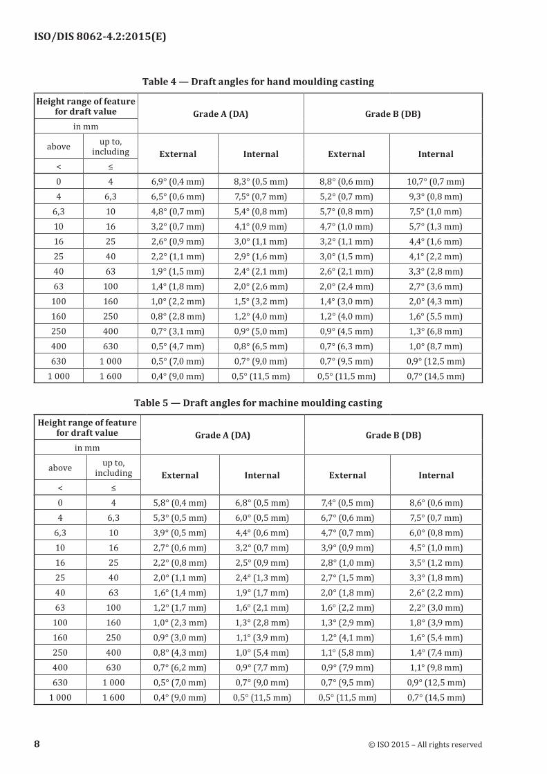
Table 4 — Draft angles for hand moulding casting
Height range of feature for draft value Grade A (DA) Grade B (DB)
in mm
above up to, including External Internal External Internal
< ≤0 4 6,9° (0,4 mm) 8,3° (0,5 mm) 8,8° (0,6 mm) 10,7° (0,7 mm)4 6,3 6,5° (0,6 mm) 7,5° (0,7 mm) 5,2° (0,7 mm) 9,3° (0,8 mm)
6,3 10 4,8° (0,7 mm) 5,4° (0,8 mm) 5,7° (0,8 mm) 7,5° (1,0 mm)10 16 3,2° (0,7 mm) 4,1° (0,9 mm) 4,7° (1,0 mm) 5,7° (1,3 mm)16 25 2,6° (0,9 mm) 3,0° (1,1 mm) 3,2° (1,1 mm) 4,4° (1,6 mm)25 40 2,2° (1,1 mm) 2,9° (1,6 mm) 3,0° (1,5 mm) 4,1° (2,2 mm)40 63 1,9° (1,5 mm) 2,4° (2,1 mm) 2,6° (2,1 mm) 3,3° (2,8 mm)63 100 1,4° (1,8 mm) 2,0° (2,6 mm) 2,0° (2,4 mm) 2,7° (3,6 mm)
100 160 1,0° (2,2 mm) 1,5° (3,2 mm) 1,4° (3,0 mm) 2,0° (4,3 mm)160 250 0,8° (2,8 mm) 1,2° (4,0 mm) 1,2° (4,0 mm) 1,6° (5,5 mm)250 400 0,7° (3,1 mm) 0,9° (5,0 mm) 0,9° (4,5 mm) 1,3° (6,8 mm)400 630 0,5° (4,7 mm) 0,8° (6,5 mm) 0,7° (6,3 mm) 1,0° (8,7 mm)630 1 000 0,5° (7,0 mm) 0,7° (9,0 mm) 0,7° (9,5 mm) 0,9° (12,5 mm)
1 000 1 600 0,4° (9,0 mm) 0,5° (11,5 mm) 0,5° (11,5 mm) 0,7° (14,5 mm)
Table 5 — Draft angles for machine moulding casting
Height range of feature for draft value Grade A (DA) Grade B (DB)
in mm
above up to, including External Internal External Internal
< ≤0 4 5,8° (0,4 mm) 6,8° (0,5 mm) 7,4° (0,5 mm) 8,6° (0,6 mm)4 6,3 5,3° (0,5 mm) 6,0° (0,5 mm) 6,7° (0,6 mm) 7,5° (0,7 mm)
6,3 10 3,9° (0,5 mm) 4,4° (0,6 mm) 4,7° (0,7 mm) 6,0° (0,8 mm)10 16 2,7° (0,6 mm) 3,2° (0,7 mm) 3,9° (0,9 mm) 4,5° (1,0 mm)16 25 2,2° (0,8 mm) 2,5° (0,9 mm) 2,8° (1,0 mm) 3,5° (1,2 mm)25 40 2,0° (1,1 mm) 2,4° (1,3 mm) 2,7° (1,5 mm) 3,3° (1,8 mm)40 63 1,6° (1,4 mm) 1,9° (1,7 mm) 2,0° (1,8 mm) 2,6° (2,2 mm)63 100 1,2° (1,7 mm) 1,6° (2,1 mm) 1,6° (2,2 mm) 2,2° (3,0 mm)
100 160 1,0° (2,3 mm) 1,3° (2,8 mm) 1,3° (2,9 mm) 1,8° (3,9 mm)160 250 0,9° (3,0 mm) 1,1° (3,9 mm) 1,2° (4,1 mm) 1,6° (5,4 mm)250 400 0,8° (4,3 mm) 1,0° (5,4 mm) 1,1° (5,8 mm) 1,4° (7,4 mm)400 630 0,7° (6,2 mm) 0,9° (7,7 mm) 0,9° (7,9 mm) 1,1° (9,8 mm)630 1 000 0,5° (7,0 mm) 0,7° (9,0 mm) 0,7° (9,5 mm) 0,9° (12,5 mm)
1 000 1 600 0,4° (9,0 mm) 0,5° (11,5 mm) 0,5° (11,5 mm) 0,7° (14,5 mm)
ISO/DIS 8062-4.2:2015(E)
8 © ISO 2015 – All rights reserved
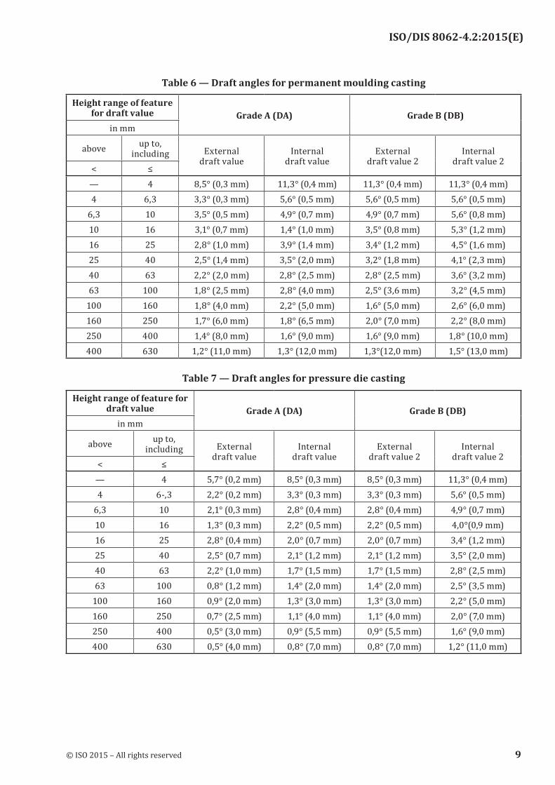
Table 6 — Draft angles for permanent moulding casting
Height range of feature for draft value Grade A (DA) Grade B (DB)
in mm
above up to, including External
draft valueInternal
draft valueExternal
draft value 2Internal
draft value 2< ≤
— 4 8,5° (0,3 mm) 11,3° (0,4 mm) 11,3° (0,4 mm) 11,3° (0,4 mm)4 6,3 3,3° (0,3 mm) 5,6° (0,5 mm) 5,6° (0,5 mm) 5,6° (0,5 mm)
6,3 10 3,5° (0,5 mm) 4,9° (0,7 mm) 4,9° (0,7 mm) 5,6° (0,8 mm)10 16 3,1° (0,7 mm) 1,4° (1,0 mm) 3,5° (0,8 mm) 5,3° (1,2 mm)16 25 2,8° (1,0 mm) 3,9° (1,4 mm) 3,4° (1,2 mm) 4,5° (1,6 mm)25 40 2,5° (1,4 mm) 3,5° (2,0 mm) 3,2° (1,8 mm) 4,1° (2,3 mm)40 63 2,2° (2,0 mm) 2,8° (2,5 mm) 2,8° (2,5 mm) 3,6° (3,2 mm)63 100 1,8° (2,5 mm) 2,8° (4,0 mm) 2,5° (3,6 mm) 3,2° (4,5 mm)
100 160 1,8° (4,0 mm) 2,2° (5,0 mm) 1,6° (5,0 mm) 2,6° (6,0 mm)160 250 1,7° (6,0 mm) 1,8° (6,5 mm) 2,0° (7,0 mm) 2,2° (8,0 mm)250 400 1,4° (8,0 mm) 1,6° (9,0 mm) 1,6° (9,0 mm) 1,8° (10,0 mm)400 630 1,2° (11,0 mm) 1,3° (12,0 mm) 1,3°(12,0 mm) 1,5° (13,0 mm)
Table 7 — Draft angles for pressure die casting
Height range of feature for draft value Grade A (DA) Grade B (DB)
in mm
above up to, including External
draft valueInternal
draft valueExternal
draft value 2Internal
draft value 2< ≤
— 4 5,7° (0,2 mm) 8,5° (0,3 mm) 8,5° (0,3 mm) 11,3° (0,4 mm)4 6-,3 2,2° (0,2 mm) 3,3° (0,3 mm) 3,3° (0,3 mm) 5,6° (0,5 mm)
6,3 10 2,1° (0,3 mm) 2,8° (0,4 mm) 2,8° (0,4 mm) 4,9° (0,7 mm)10 16 1,3° (0,3 mm) 2,2° (0,5 mm) 2,2° (0,5 mm) 4,0°(0,9 mm)16 25 2,8° (0,4 mm) 2,0° (0,7 mm) 2,0° (0,7 mm) 3,4° (1,2 mm)25 40 2,5° (0,7 mm) 2,1° (1,2 mm) 2,1° (1,2 mm) 3,5° (2,0 mm)40 63 2,2° (1,0 mm) 1,7° (1,5 mm) 1,7° (1,5 mm) 2,8° (2,5 mm)63 100 0,8° (1,2 mm) 1,4° (2,0 mm) 1,4° (2,0 mm) 2,5° (3,5 mm)
100 160 0,9° (2,0 mm) 1,3° (3,0 mm) 1,3° (3,0 mm) 2,2° (5,0 mm)160 250 0,7° (2,5 mm) 1,1° (4,0 mm) 1,1° (4,0 mm) 2,0° (7,0 mm)250 400 0,5° (3,0 mm) 0,9° (5,5 mm) 0,9° (5,5 mm) 1,6° (9,0 mm)400 630 0,5° (4,0 mm) 0,8° (7,0 mm) 0,8° (7,0 mm) 1,2° (11,0 mm)
ISO/DIS 8062-4.2:2015(E)
© ISO 2015 – All rights reserved 9

Table 8 — Draft angles for investment casting
Height range of feature for draft value Grade A (DA) Grade B (DB)
in mm
above up to, including External
draft valueInternal
draft valueExternal
draft value 2Internal
draft value 2< ≤
— 4 5,7° (0,2 mm) 5,7° (0,2 mm) 5,7° (0,2 mm) 8,5° (0,3 mm)4 6,3 2,2° (0,2 mm) 2,2° (0,2 mm) 2,2° (0,2 mm) 3,3° (0,3 mm)
6,3 10 1,4° (0,2 mm) 1,4° (0,2 mm) 1,4° (0,2 mm) 2,8° (0,4 mm)10 16 0,9° (0,2 mm) 1,3° (0,3 mm) 1,3° (0,3 mm) 1,8° (0,4 mm)16 25 0,8° (0,3 mm) 1,1° (0,4 mm) 1,1° (0,4 mm) 1,4° (0,5 mm)25 40 0,5° (0,3 mm) 0,7° (0,4 mm) 0,7° (0,4 mm) 1,1° (0,6 mm)40 63 0,5° (0,4 mm) 0,6° (0,5 mm) 0,6° (0,5 mm) 0,8° (0,7 mm)63 100 0,3° (0,4 mm) 0,4° (0,6 mm) 0,4° (0,6 mm) 0,6° (0,8 mm)
100 160 0,2° (0,5 mm) 0,3° (0,7 mm) 0,3° (0,7 mm) 0,4° (0,9 mm)160 250 0,2° (0,6 mm) 0,2° (0,8 mm) 0,2° (0,8 mm) 0,3° (1,0 mm)250 400 0,1° (0,7 mm) 0,2° (0,9 mm) 0,2° (0,9 mm) 0,2° (1,2 mm)400 630 0,1° (0,8 mm) 0,1° (1,0 mm) 0,1° (1,0 mm) 0,2° (1,5 mm)
NOTE The overall dimension rating is finer than that in Tables 4 to 8, in order to avoid excess material.
8 General drawing indication
In order to apply the general tolerances according to this standard, the following items shall be specified in, or near to, the drawing title block:
— the number of this standard: ISO 8062-4;
— the general profile tolerance;
— the general tolerance grade for sizes;
— the general tolerance grade for wall thicknesses;
— the RMA value;
— manufacturing method together with the draft angle grade;
— the casting size S∅ of smallest enveloping sphere;
— the part condition identifier(s).
e. g.: ISO 8062-4.
Sizes S8
Wall thicknesses S9
RMA-1,8
ISO/DIS 8062-4.2:2015(E)
10 © ISO 2015 – All rights reserved

Machine moulding DB
Casting size S∅ 750
ISO/DIS 8062-4.2:2015(E)
© ISO 2015 – All rights reserved 11
Annex A (informative)
Concept of the general tolerancing
General tolerances according to this part of ISO 8062 are surface profile tolerances related to a datum target system RST. The datum target system is established by 6 datum targets for rigid workpieces and by a minimum of 6 datum targets for flexible workpieces. The datum targets are indicated in the drawing.
The general tolerances on surface profile apply in principle to all surfaces of the workpiece. In special cases, larger or smaller profile surface tolerances related to the same datum system may be individually indicated for particular surfaces. Individually specified tolerances directly or indirectly related to the general datum system or parts of it override the general tolerances.
For sizes, general positional tolerances related to the same datum target system RST may be specified, overruling the general profile surface tolerances.
Other individually indicated tolerances are complementary, i.e. they apply in addition as a further restriction to the general tolerances.
Dimensional tolerances (±tolerances) should only be used when necessary and only for diameters and widths (sizes) together with positional tolerances, and for wall thicknesses.
In order to achieve the full economic success, the general tolerances are to be respected without special effort and with a high probability. The corresponding amount of the general tolerances shall be derived from measurements on workpieces out of the normal production, see Figure A.1.
According to this investigation, the general tolerances are to be selected from the tables of the standard.
By the use of general tolerances, the drawings become easier to read because there are fewer individually indicated tolerances. Manufacturing planners and inspectors can recognize the individually indicated tolerances. These are the tolerances where eventually special care is necessary. This facilitates an economic way of production.
The foundry should determine by measurements what its customary foundry accuracy is and accept only those drawings which have general tolerances equal to or larger than its customary foundry accuracy.
NOTE It is not the intention of the concept of general tolerancing to check every feature on every casting. Relying on the notion of undefined “good foundry”, with all its uncertainties and misunderstandings, is no longer necessary with the concept of general tolerances. The general tolerances define the required accuracy of “good foundry”.
ISO/DIS 8062-4.2:2015(E)
12 © ISO 2015 – All rights reserved

Key1 profile deviation2 general profile tolerance3 extracted feature (actual surface)4 general profile deviation limit5 theoretical exact feature (workpiece shape)
X workpiece overall size (smallest enveloping sphere diameter)Y max. profile deviation of workpiece (measured)
Figure A.1 — General tolerances derived from measurements (the limit deviations correspond to half of the profile surface tolerances)
The tolerance that the function allows is often larger than the general tolerance. The function of the part is, therefore, not always impaired if the general tolerance is (occasionally) exceeded at any feature of the casting. Exceeding the general tolerance should lead to a rejection of the casting only if the function is impaired.
ISO/DIS 8062-4.2:2015(E)
© ISO 2015 – All rights reserved 13

Annex B (informative)
Selection of general tolerances
See Tables B.1 and B.2.
Table B.1 — Tolerance grades P for general tolerances for long-series or mass production of castings
Sand cast hand
moulding
Sand cast machine mould
and shell moulding
Metallic permanent
mouldPressure die
castingInvestment
casting
Steel 11 - 14 8 - 12 — — 4 - 9Grey iron 11 - 14 8 - 12 7 - 9 — 4 - 9S. G. iron 11 - 14 8 - 12 7 - 9 — 4 - 9
Malleable iron 11 - 14 8 - 12 7 - 9 — 4 - 9Copper alloys 10 - 13 8 - 10 7 - 9 6 - 8 4 - 9
Zinc alloys 10 - 13 8 - 10 7 - 9 3 - 6 4 - 9Light metal alloys 9 - 12 7 - 9 6 - 8 6 - 9 4 - 9
Nickel based alloys 11 - 14 8 - 12 — — 4 - 9Cobalt based alloys 11 - 14 8 - 12 — — 4 - 9
Table B.2 — Tolerance grades P for general tolerances for short-series or single production of castings
Sand cast hand mouldingClay-bonded Chemically bonded
Steel 13 - 14 12 - 14Grey iron 13 - 15 11 - 14S. G. iron 13 - 15 11 - 14
Malleable iron 13 - 15 11 - 14Copper alloys 13 - 15 10 - 13
Light metal alloys 11 - 13 10 - 13Nickel based alloys 13 - 15 12 - 14Cobalt based alloys 13 - 15 12 - 14
ISO/DIS 8062-4.2:2015(E)
14 © ISO 2015 – All rights reserved

Annex C (informative)
Selection of required machining allowances (RMA)
Sand cast hand moulding
Sand cast machine mould
and shell moulding
Metallic permanent
mouldPressure die
castingInvestment
casting
Steel G to K F to H — — EGrey iron F to H E to G D to F — ES. G. iron F to H E to G D to F — E
Malleable iron F to H E to G D to F — —Copper alloys F to H E to G D to F B to D E
Zinc alloys F to H E to G D to F A to D —Light metal alloys F to H E to G D to F B to D E
Nickel based alloys G to K F to H — — ECobalt based alloys G to K F to H — — —
ISO/DIS 8062-4.2:2015(E)
© ISO 2015 – All rights reserved 15
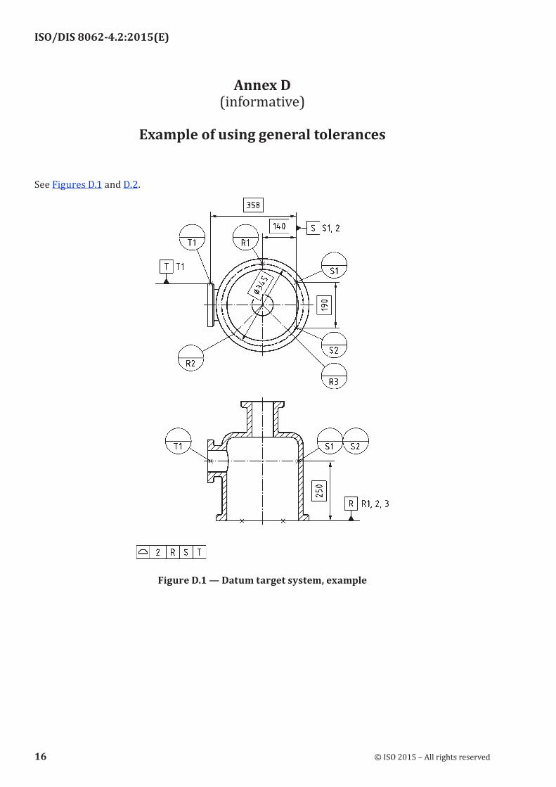
Annex D (informative)
Example of using general tolerances
See Figures D.1 and D.2.
Figure D.1 — Datum target system, example
ISO/DIS 8062-4.2:2015(E)
16 © ISO 2015 – All rights reserved

a) Drawing indication
ISO/DIS 8062-4.2:2015(E)
© ISO 2015 – All rights reserved 17

b) Interpretation
Figure D.2 — Use of general tolerances with exceptions and additional further restrictions
General dimensional tolerances for cylindrical sizes are not required, regarding parting surface and draft angles the drawing is not complete. As there occurs only one wall thickness in the drawing, the general dimensional tolerance for wall thickness has been indicated directly; it corresponds to S9.
ISO/DIS 8062-4.2:2015(E)
18 © ISO 2015 – All rights reserved
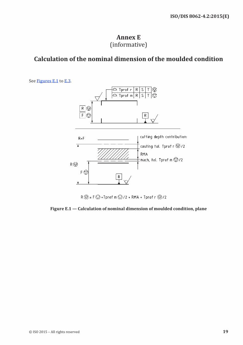
Annex E (informative)
Calculation of the nominal dimension of the moulded condition
See Figures E.1 to E.3.
Figure E.1 — Calculation of nominal dimension of moulded condition, plane
ISO/DIS 8062-4.2:2015(E)
© ISO 2015 – All rights reserved 19

Figure E.2 — Calculation of nominal dimension of moulded condition, shaft, profile tolerance for machined condition
ISO/DIS 8062-4.2:2015(E)
20 © ISO 2015 – All rights reserved

Figure E.3 — Calculation of nominal dimension of moulded condition, shaft, size and positional tolerance for machined condition
ISO/DIS 8062-4.2:2015(E)
© ISO 2015 – All rights reserved 21
Annex F (informative)
Relation to the GPS matrix model
F.1 General
The ISO GPS matrix model given in ISO 14638 gives an overview of the ISO GPS system of which this standard is a part.
F.2 Information about the standard and its use
This part of ISO 8062 specifies a system of general dimensional and geometrical tolerances, as well as machining allowance grades, for castings as delivered to the purchaser. It is applicable for the tolerancing of dimensions and geometry of castings in all cast metals and their alloys produced by various casting manufacturing processes.
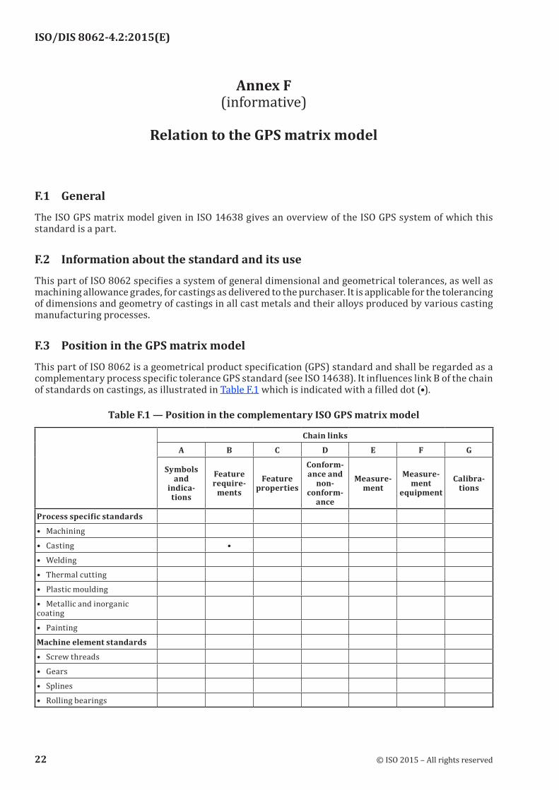
F.3 Position in the GPS matrix model
This part of ISO 8062 is a geometrical product specification (GPS) standard and shall be regarded as a complementary process specific tolerance GPS standard (see ISO 14638). It influences link B of the chain of standards on castings, as illustrated in Table F.1 which is indicated with a filled dot (•).
Table F.1 — Position in the complementary ISO GPS matrix model
Chain links
A B C D E F G
Symbols and
indica-tions
Feature require-
mentsFeature
properties
Conform-ance and
non-conform-
ance
Measure-ment
Measure-ment
equipmentCalibra-
tions
Process specific standards
• Machining
• Casting •
• Welding
• Thermal cutting
• Plastic moulding
• Metallic and inorganic coating
• Painting
Machine element standards
• Screw threads
• Gears
• Splines
• Rolling bearings
ISO/DIS 8062-4.2:2015(E)
22 © ISO 2015 – All rights reserved

Bibliography
[1] ISO 8015:2011, Geometrical product specifications (GPS) — Fundamentals — Concepts, principles and rules
[2] ISO 14638:2015, Geometrical product specifications (GPS) — Matrix model
ISO/DIS 8062-4.2:2015(E)
© ISO 2015 – All rights reserved 23

ISO/DIS 8062-4.2:2015(E)
© ISO 2015 – All rights reserved
ICS 17.040.10Price based on 23 pages