G É OMÉTRIE ET VISION ARTIFICIELLE
54
GÉOMÉTRIE ET VISION ARTIFICIELLE Jean Ponce “Hauts du DI” Email: [email protected] Web: http://www.di.ens.fr/~ponce Référence: “Computer Vision: A Modern Approach” par D.A. Forsyth et J. Ponce (Prentice-Hall, 2002)
-
Upload
sebastian-sykes -
Category
Documents
-
view
40 -
download
0
description
G É OMÉTRIE ET VISION ARTIFICIELLE. Jean Ponce “Hauts du DI” Email: [email protected] Web: http://www.di.ens.fr/~ponce R é férence: “Computer Vision: A Modern Approach” par D.A. Forsyth et J. Ponce (Prentice-Hall, 2002). Informations pratiques. - PowerPoint PPT Presentation
Transcript of G É OMÉTRIE ET VISION ARTIFICIELLE
GÉOMÉTRIE ET VISION ARTIFICIELLE
Jean Ponce“Hauts du DI”Email: [email protected]: http://www.di.ens.fr/~ponce
Référence:“Computer Vision: A Modern Approach” par D.A. Forsyth et J. Ponce (Prentice-Hall, 2002)
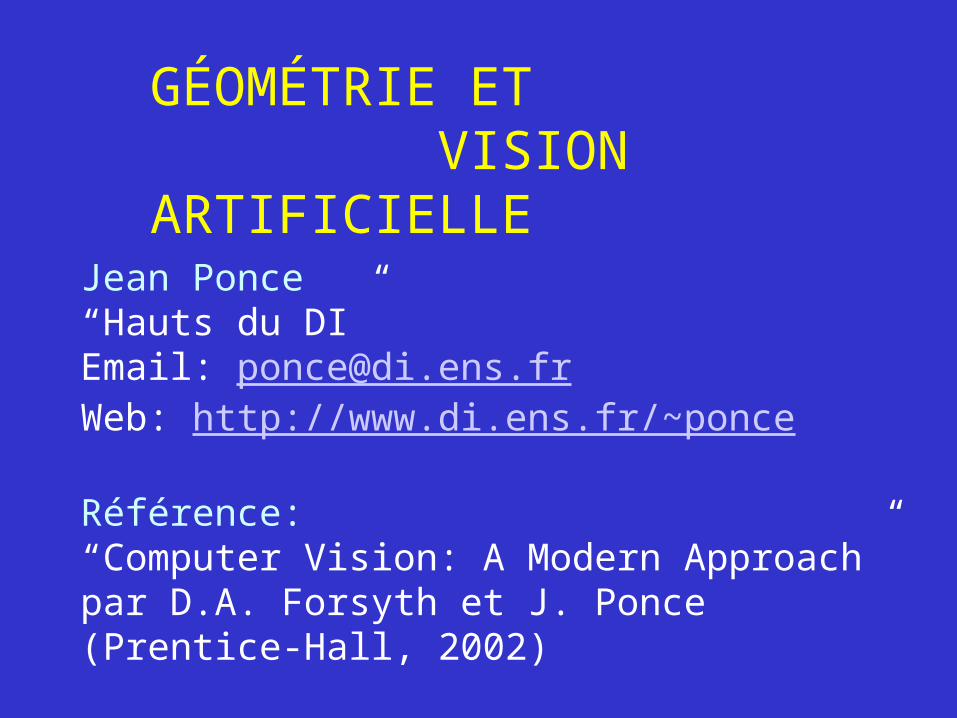
Informations pratiques
• Présentations : http://www.di.ens.fr/~ponce/geomvis/lect1.ppt http://www.di.ens.fr/~ponce/geomvis/lect1.pdf
• Séminaires :
http://www.di.ens.fr/~ponce/seminaires.html
• Exceptionnellement, le cours du jeudi 20 Octobre est déplacé au lundi 24 Octobre, 17h45—19h45.
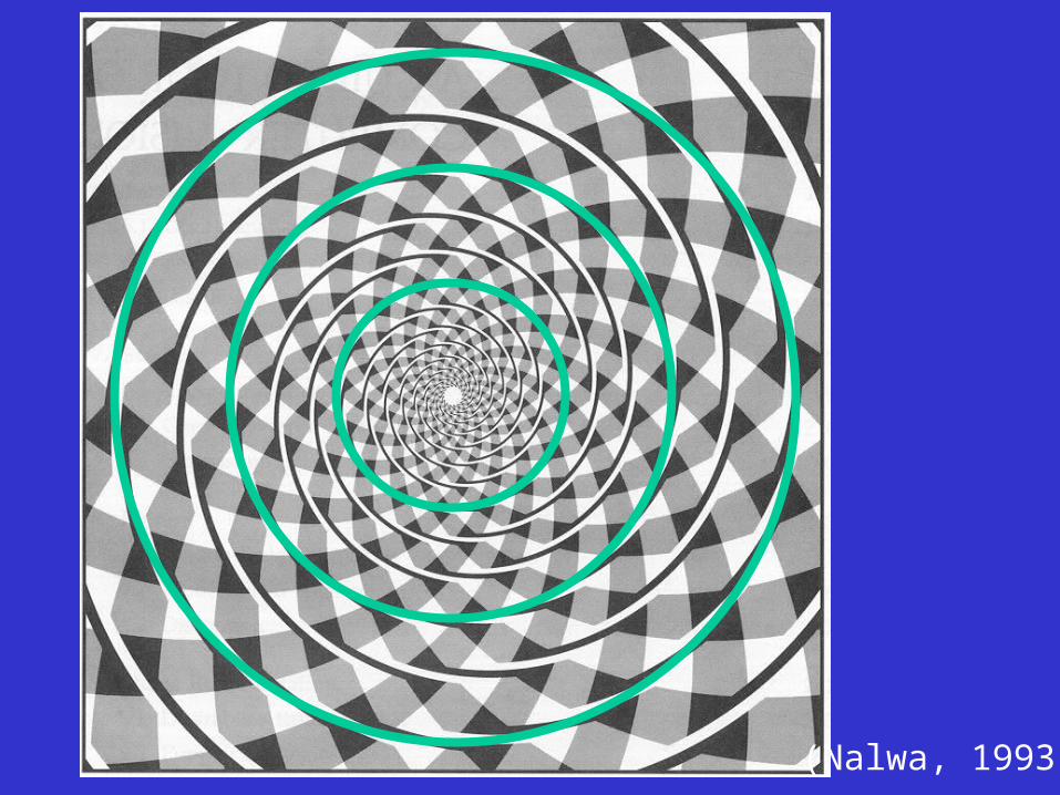
(Nalwa, 1993)
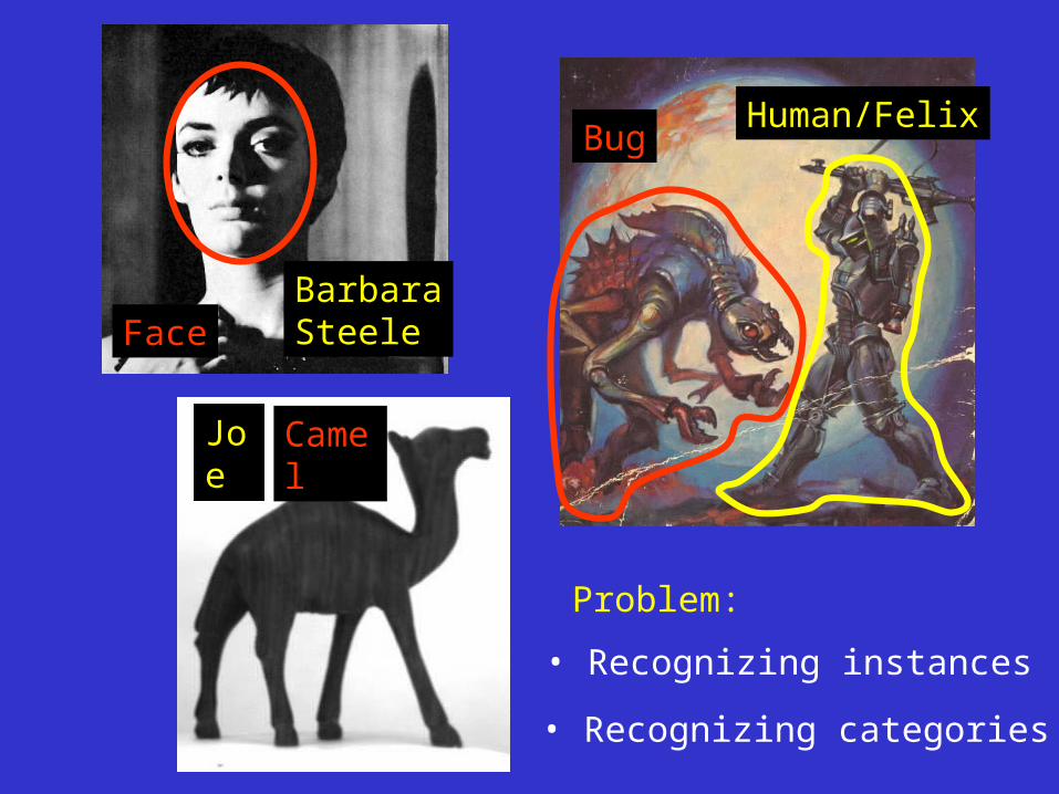
Face
Camel
BugHuman/Felix
Joe
BarbaraSteele
Problem:
• Recognizing instances
• Recognizing categories
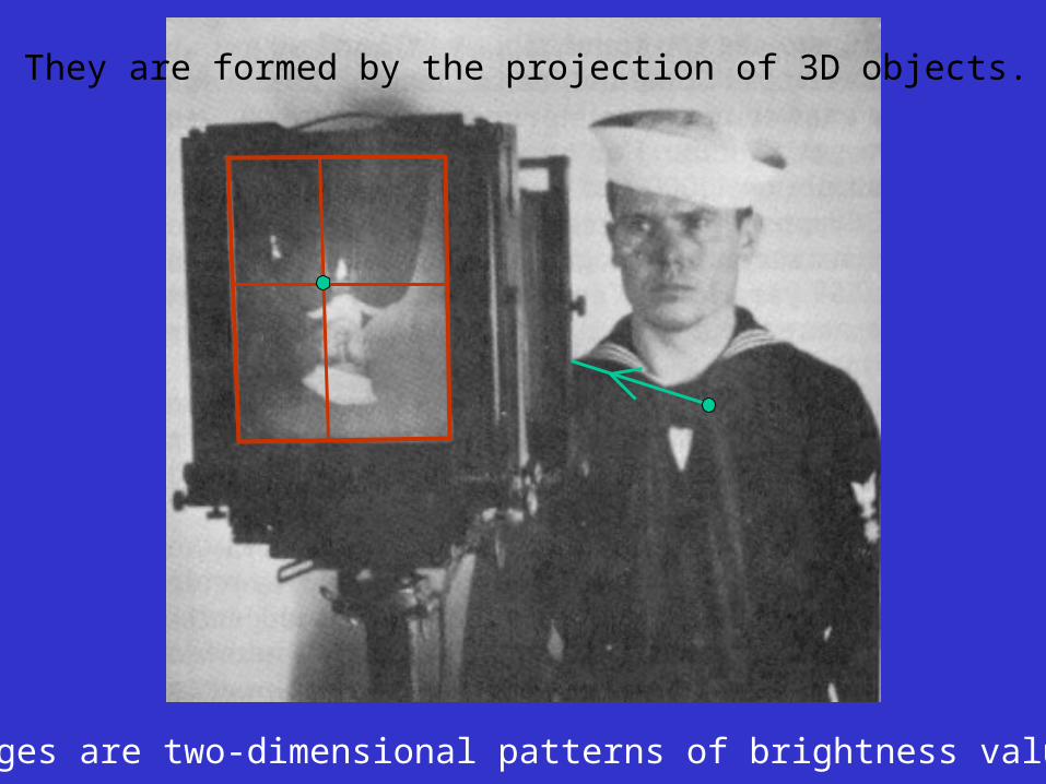
Images are two-dimensional patterns of brightness values.
They are formed by the projection of 3D objects.
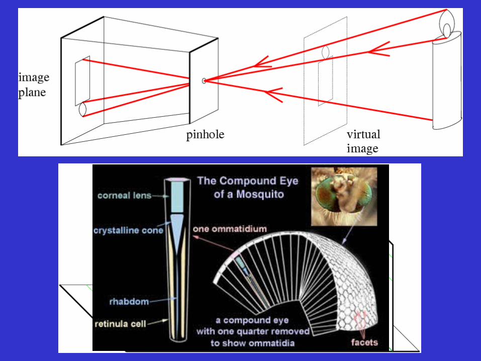
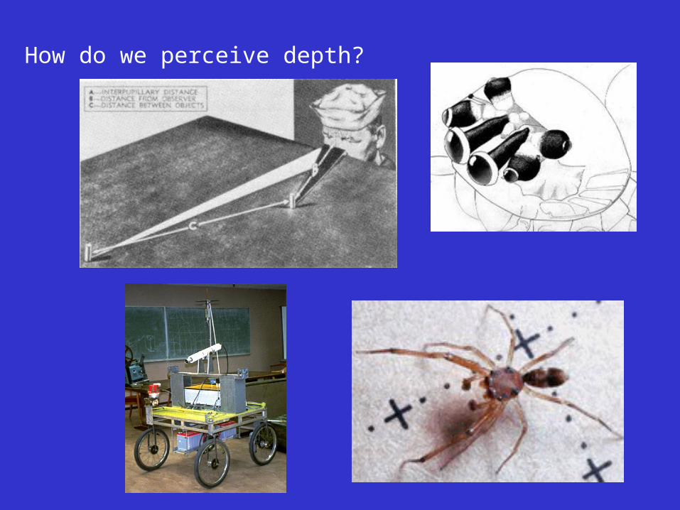
How do we perceive depth?
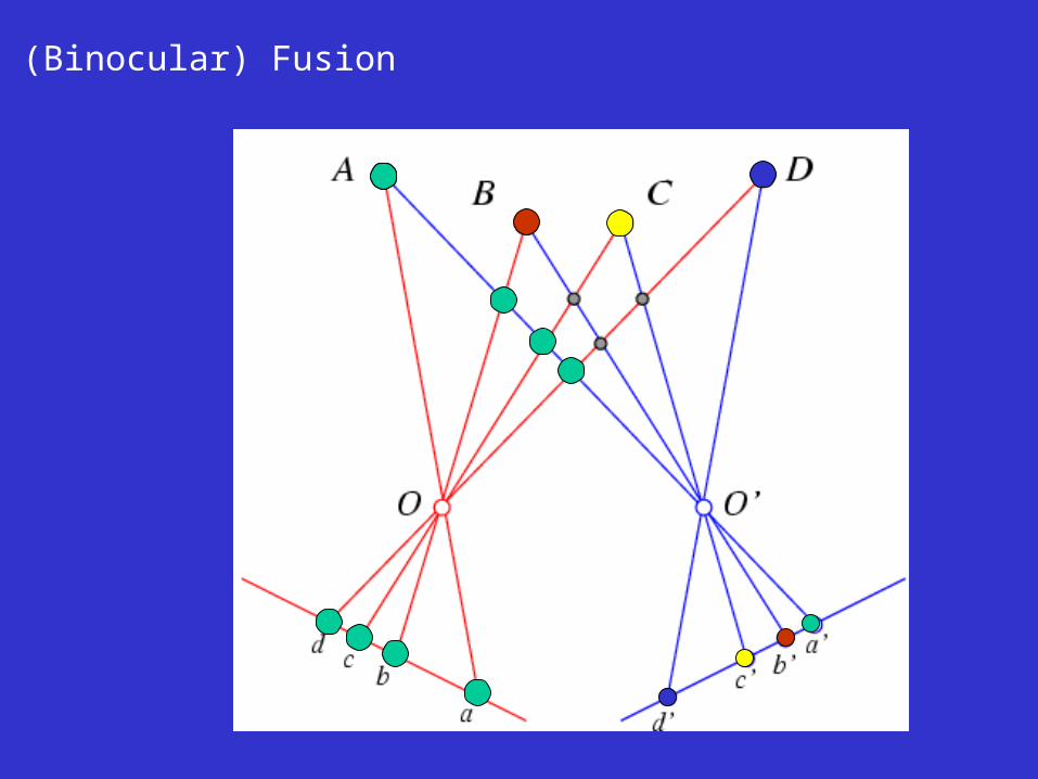
(Binocular) Fusion
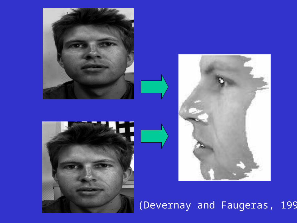
(Devernay and Faugeras, 1994)
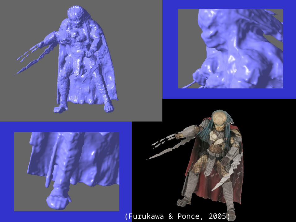
(Furukawa & Ponce, 2005)
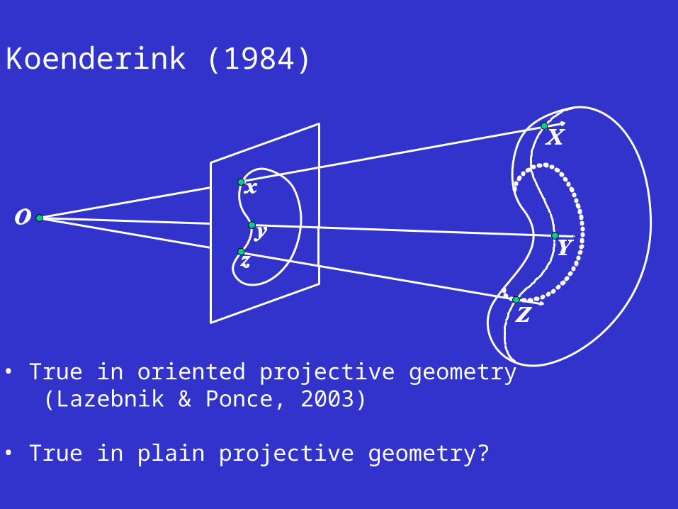
Koenderink (1984)
• True in oriented projective geometry (Lazebnik & Ponce, 2003)
• True in plain projective geometry?
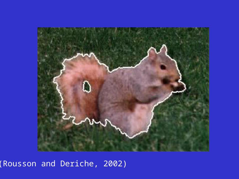
(Rousson and Deriche, 2002)
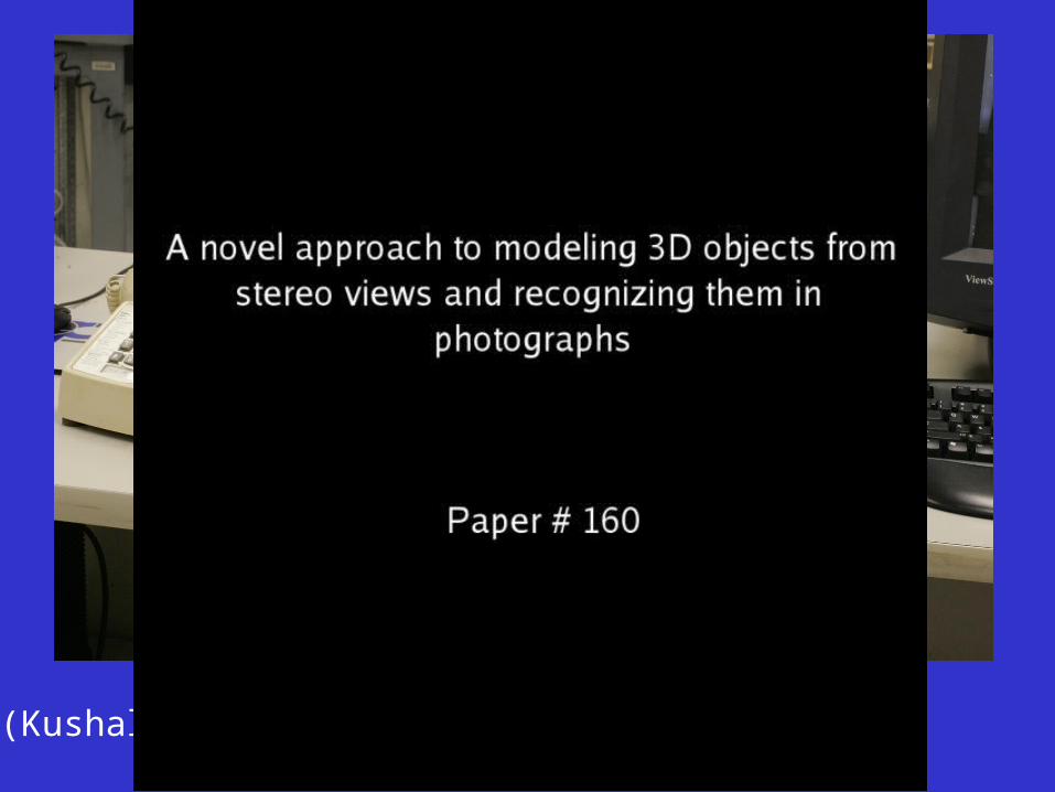
(Kushal and Ponce, 2006)
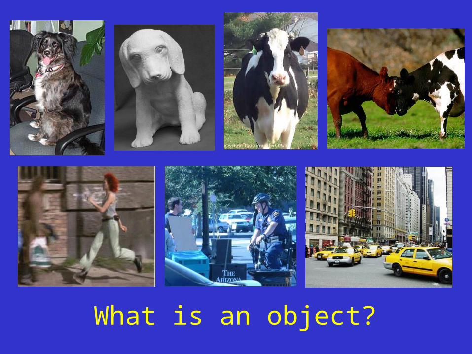
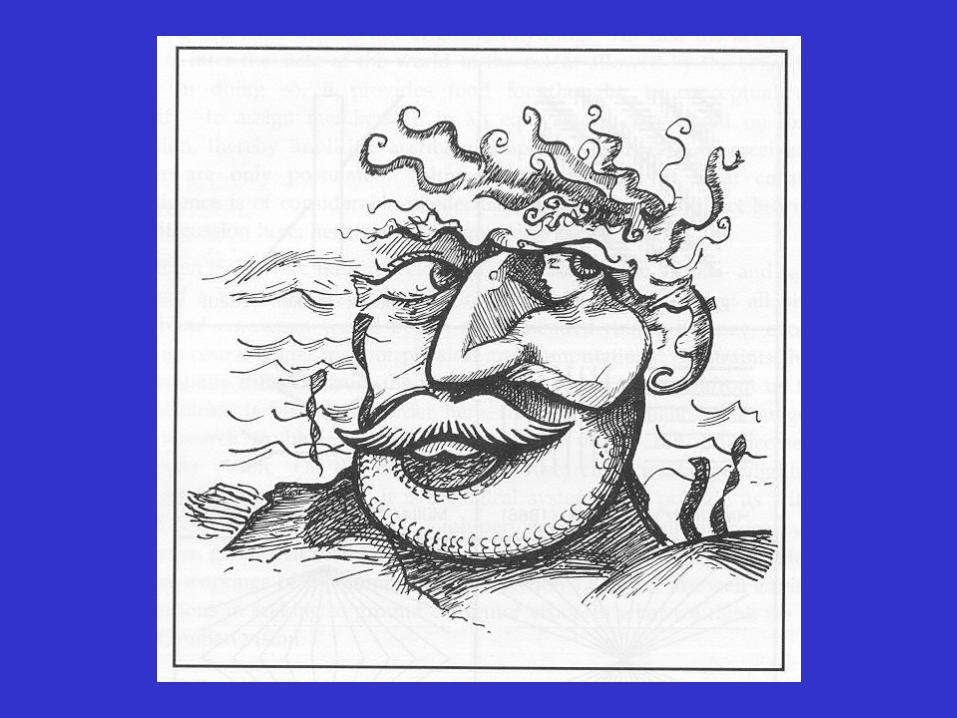
What is an object?
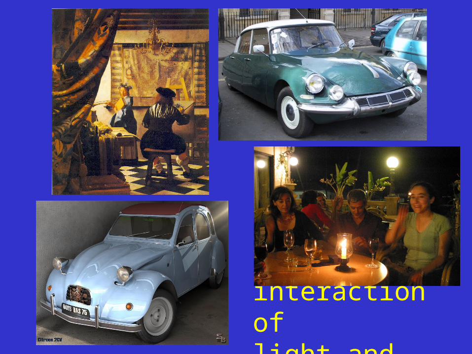
The interaction of light and matter
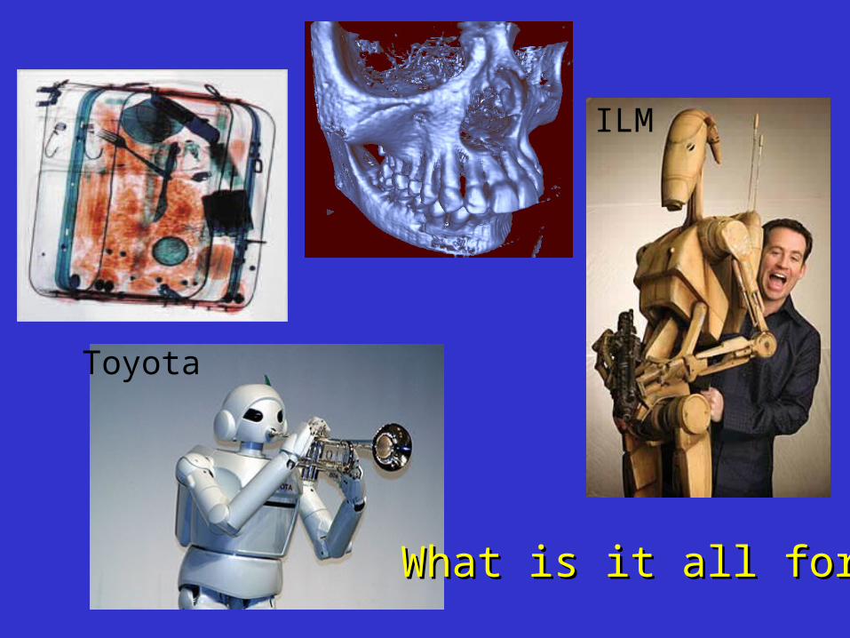
What is it all for?What is it all for?
Toyota
ILM
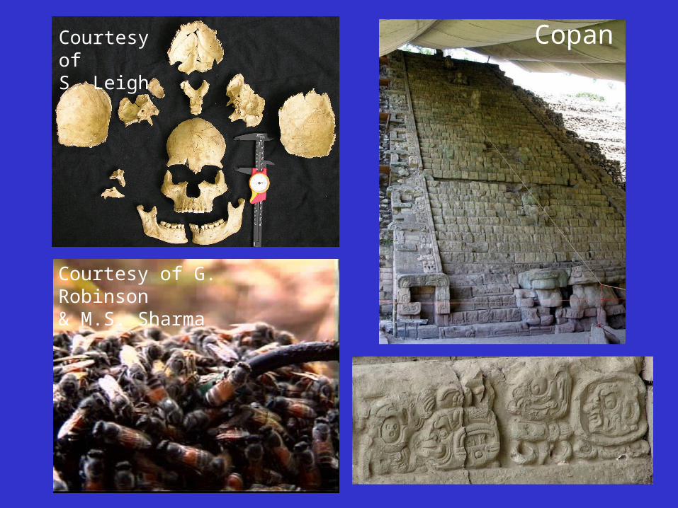
CopanCourtesy ofS. Leigh
Courtesy of G. Robinson& M.S. Sharma
CONTENU: Le but de la vision artificielle est l'interprétation automatique par un ordinateur du contenu d'une image (photographie) ou d'un ensemble d'images (photographies multiples, vidéos). Son champ d'applications est très riche: imagerie médicale; infographie et effets spéciaux dans le cadre du cinéma, de la télévision et des jeux vidéo; modélisation de la vision animale et humaine; robotique en milieu hostile et dans l'espace; surveillance et sécurité; etc. Ce cours est consacré à un aspect fondamental de la vision artificielle---la modèlisation géométrique du processus de formation des images. On y étudie différents types de caméras, ainsi que les contraintes géométriques qui relient points, droites, plans, et surfaces à leurs images, qu'elles soient observées dans une photographie ou dans une vidéo.
Le cours est destiné aux informaticiens, qui y trouveront un cadre rigoureux pour le développement d'algorithmes appliqués à l'infographie, la métrologie, et même l'anthropologie; aux mathématiciens, qui y trouveront une application concrète de concepts géométriques élémentaires mais non triviaux; et, de manière plusgénérale, aux élèves intéressés par les aspects géométriques de la vision, qu'elle soit animale ou artificielle.
PLAN DU COURS:
1. Introduction générale 2. Caméras Euclidiennes : perspective centrale, projection parallèle; modèles non standard---rétines sphériques, perspective non centrale, caméras omnidirectionnelles; paramètres intrinsèques et extrinsèques; mires et étalonnage Euclidien.
3. Caméras projectives : éléments de géométrie projective et de géométrie des droites; projection et projection inverse de points et de droites.
4. Ensembles de caméras : géométrie épipolaire; tenseur trifocal; étalonnage projectif; applications à la stéréovision.
5. Analyse du mouvement : caméras étalonnées et mouvement Euclidien; caméras générales et mouvement affine ou projectif.
6. Étalonnage Euclidien sans mire : la conique absolue de Chasles et ses cousines; applications à la modélisation de scènes à partir de vidéos.
7. Les surfaces Euclidiennes lisses et leurs silhouettes : éléments de géométrie différentielle descriptive; le théorème de Koenderink et les graphes d'aspects.
8. Les surfaces projectives lisses et leurs silhouettes : éléments de géométrie différentielle projective orientée; les enveloppes visuelles; applications à la modèlisation d'objets à partir de plusieurs images.
9. Perspectives.
Euclidean Cameras
• Pinhole perspective projection• Orthographic and weak-perspective models• Non-standard models• A detour through sensing country• Intrinsic and extrinsic parameters• Strong (Euclidean) calibration
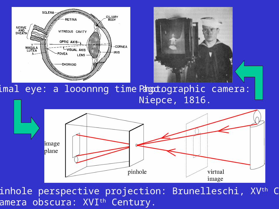
Animal eye: a looonnng time ago.
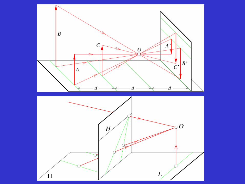
Pinhole perspective projection: Brunelleschi, XVth Century.Camera obscura: XVIth Century.
Photographic camera:Niepce, 1816.
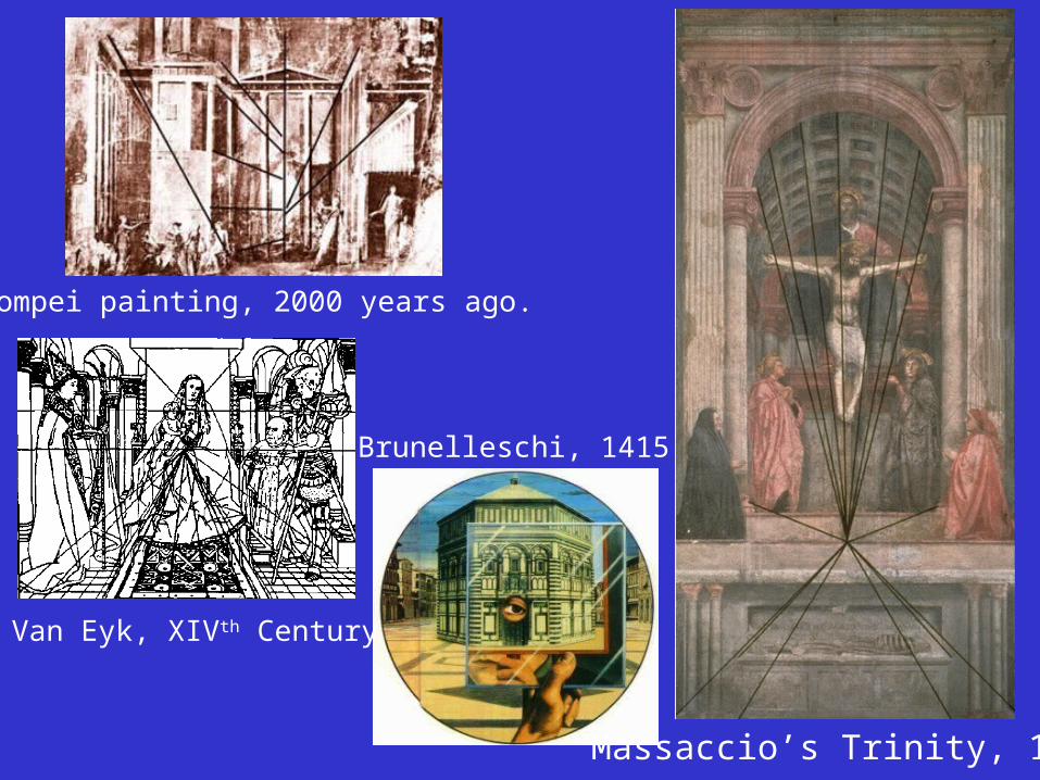
Massaccio’s Trinity, 1425
Pompei painting, 2000 years ago.
Van Eyk, XIVth Century
Brunelleschi, 1415
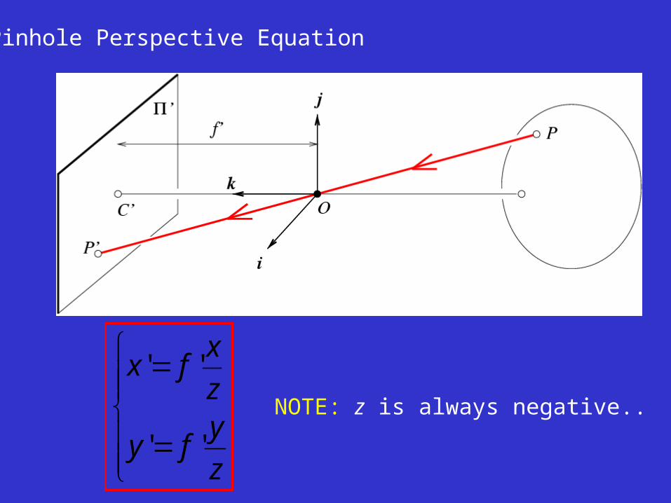
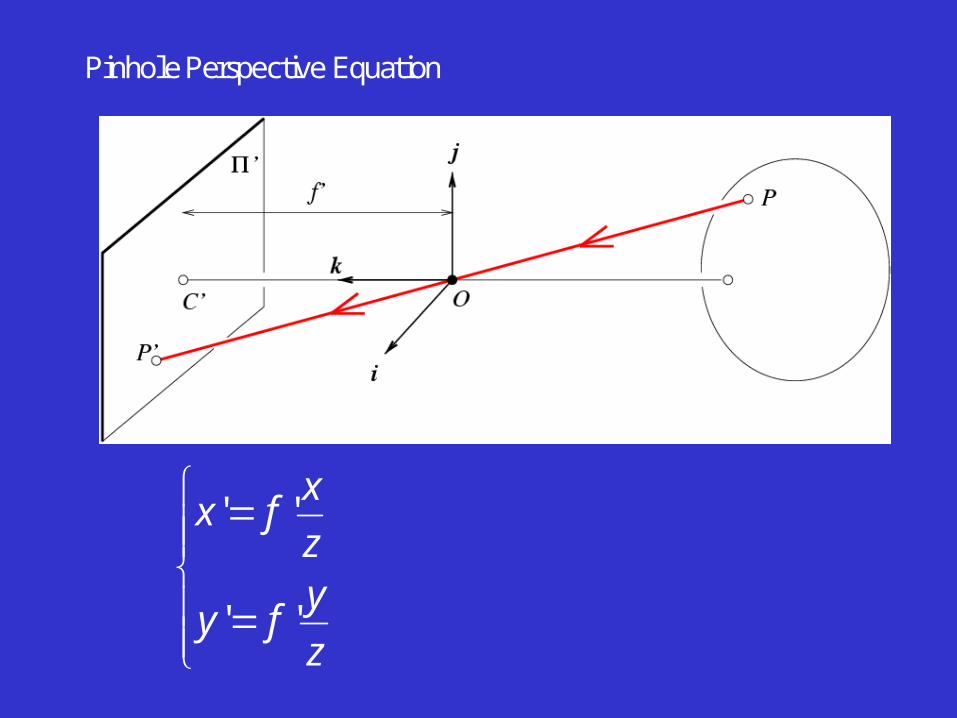
Pinhole Perspective Equation
z
yfy
z
xfx
''
''NOTE: z is always negative..
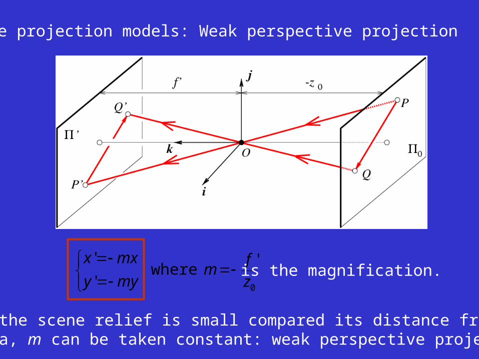
Affine projection models: Weak perspective projection
0
'where
'
'
z
fm
myy
mxx
is the magnification.
When the scene relief is small compared its distance from theCamera, m can be taken constant: weak perspective projection.
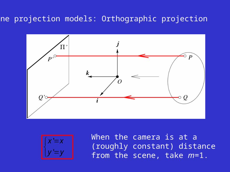
Affine projection models: Orthographic projection
yy
xx
'
' When the camera is at a(roughly constant) distancefrom the scene, take m=1.
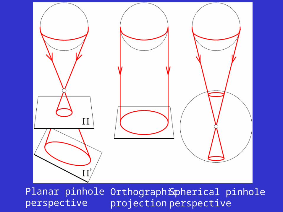
Planar pinhole perspective
Orthographicprojection
Spherical pinholeperspective
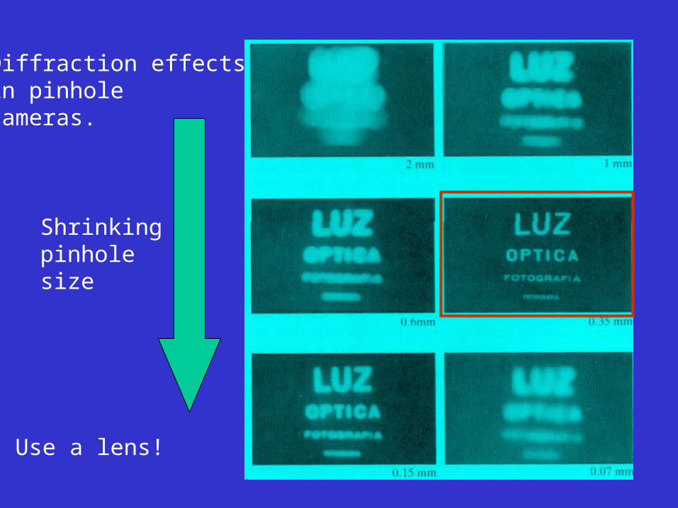
Diffraction effectsin pinhole cameras.
Shrinkingpinholesize
Use a lens!
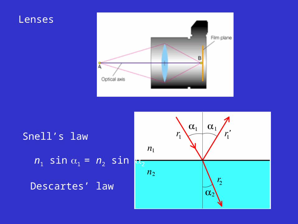
Lenses
Snell’s law
n1 sin 1 = n2 sin 2
Descartes’ law
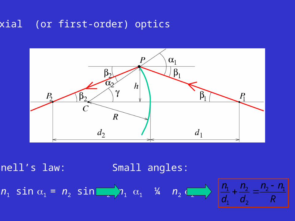
Paraxial (or first-order) optics
Snell’s law:
n1 sin 1 = n2 sin 2
Small angles:
n1 1 ¼ n2 2 R
nn
d
n
d
n 12
2
2
1
1
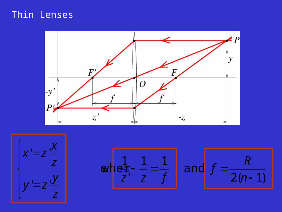
Thin Lenses
)1(2 and
11
'
1 e wher
''
''
n
Rf
fzz
z
yzy
z
xzx
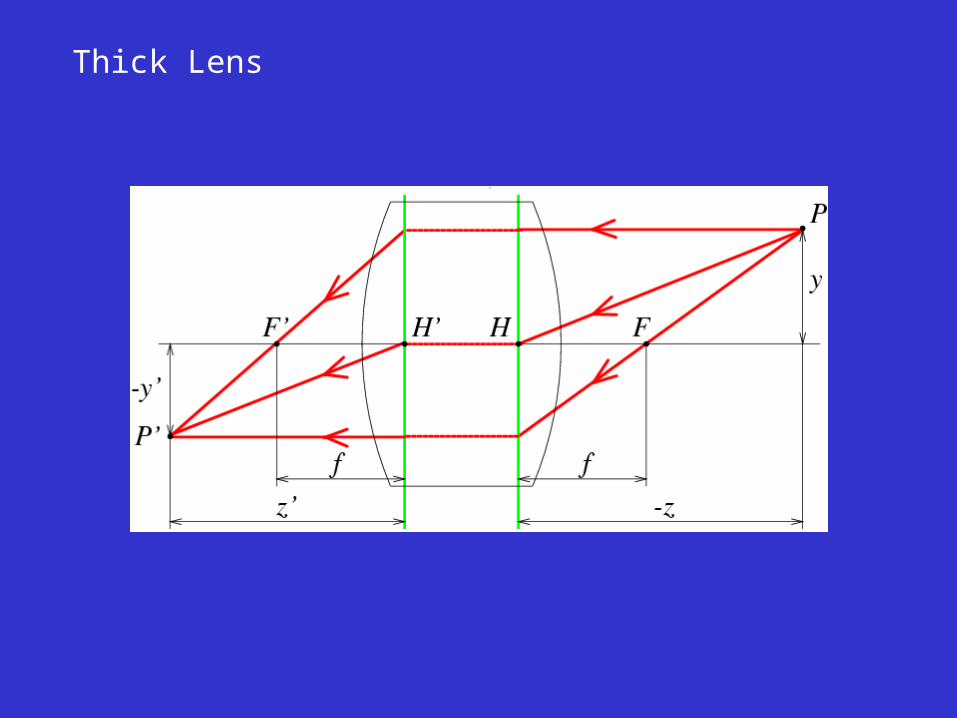
Thick Lens
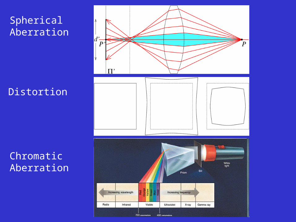
SphericalAberration
Distortion
ChromaticAberration
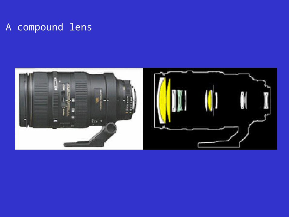
A compound lens
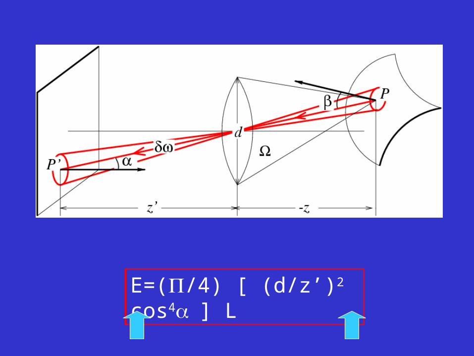
E=(/4) [ (d/z’)2 cos4] L
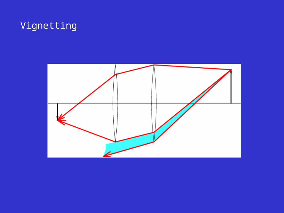
Vignetting
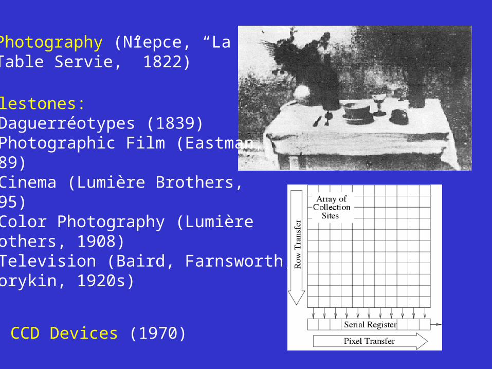
Photography (Niepce, “La Table Servie,” 1822)
Milestones: • Daguerréotypes (1839)• Photographic Film (Eastman,1889)• Cinema (Lumière Brothers,1895)• Color Photography (LumièreBrothers, 1908)• Television (Baird, Farnsworth,Zworykin, 1920s)
CCD Devices (1970)
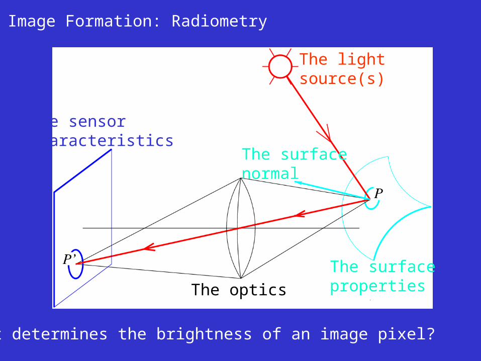
Image Formation: Radiometry
What determines the brightness of an image pixel?
The lightsource(s)
The surfacenormal
The surfacepropertiesThe optics
The sensorcharacteristics
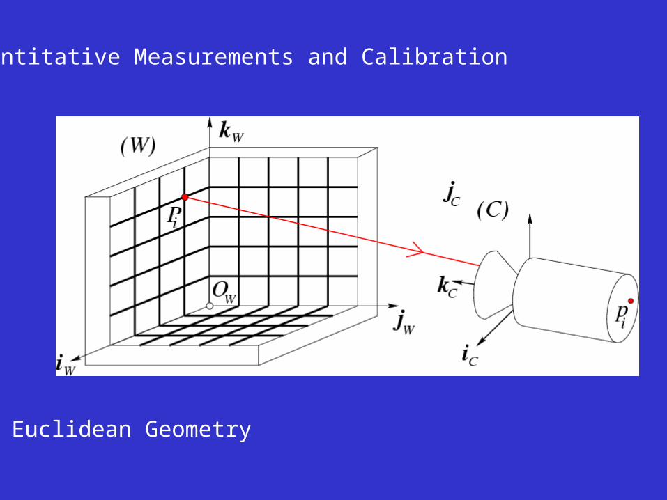
Quantitative Measurements and Calibration
Euclidean Geometry
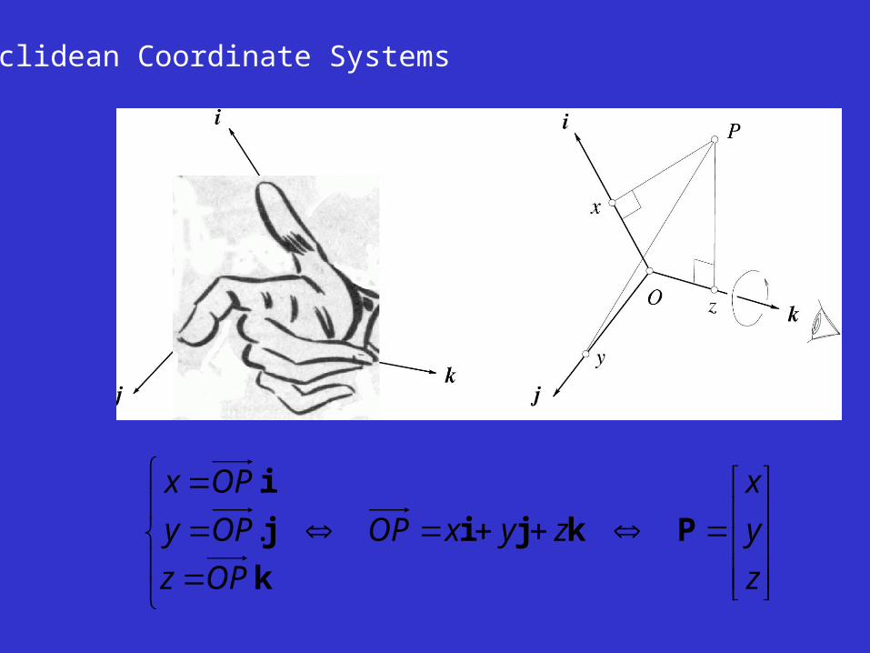
Euclidean Coordinate Systems
z
y
x
zyxOP
OPz
OPy
OPx
Pkji
k
j
i
.
.
.
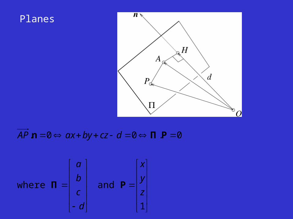
Planes
1
and where
0.00.
z
y
x
d
c
b
a
dczbyaxAP
PΠ
PΠn
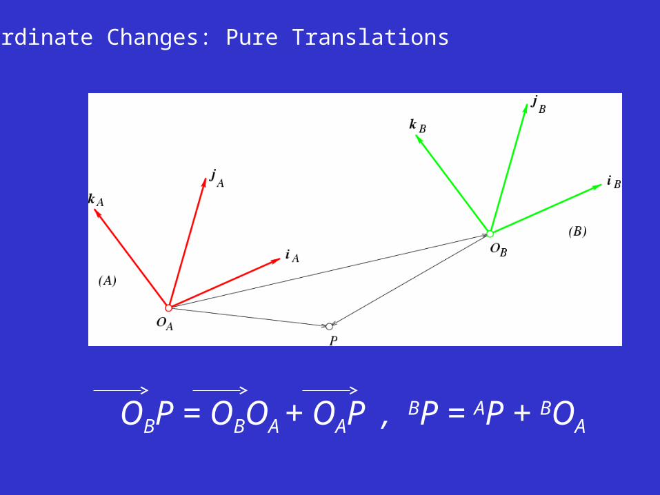
Coordinate Changes: Pure Translations
OBP = OBOA + OAP , BP = AP + BOA
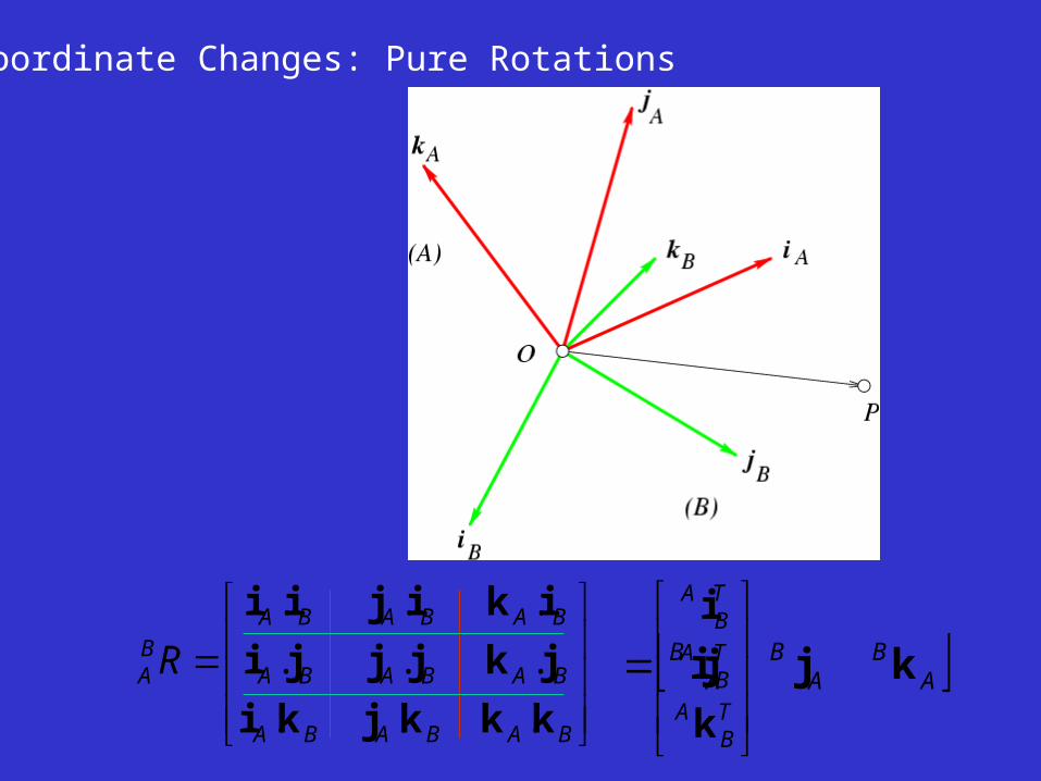
Coordinate Changes: Pure Rotations
BABABA
BABABA
BABABABA R
kkkjki
jkjjji
ikijii
...
...
...
TB
A
TB
A
TB
A
k
j
i
AB
AB
AB kji
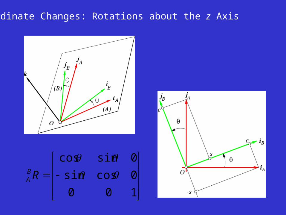
Coordinate Changes: Rotations about the z Axis
100
0cossin
0sincos
RBA
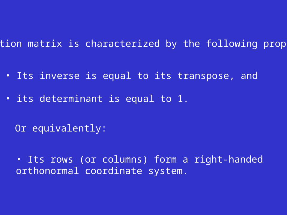
A rotation matrix is characterized by the following properties:
• Its inverse is equal to its transpose, and
• its determinant is equal to 1.
Or equivalently:
• Its rows (or columns) form a right-handedorthonormal coordinate system.
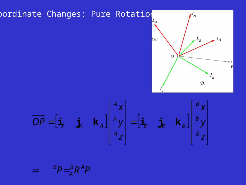
Coordinate Changes: Pure Rotations
PRP
z
y
x
z
y
x
OP
ABA
B
B
B
B
BBBA
A
A
AAA
kjikji
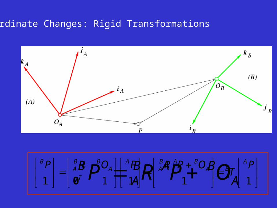
Coordinate Changes: Rigid Transformations
ABAB
AB OPRP
11111
PT
OPRPORP ABA
ABAB
AA
TA
BBA
B
0
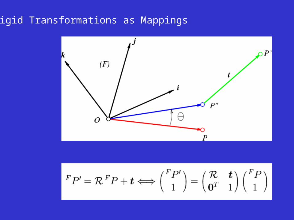
Rigid Transformations as Mappings
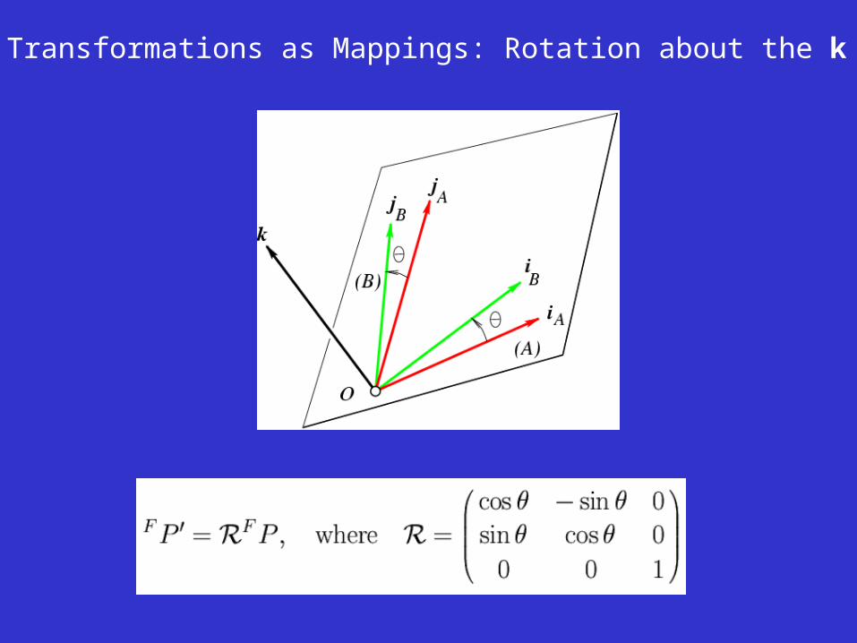
Rigid Transformations as Mappings: Rotation about the k Axis
Pinhole Perspective Equation
z
yfy
z
xfx
''
''
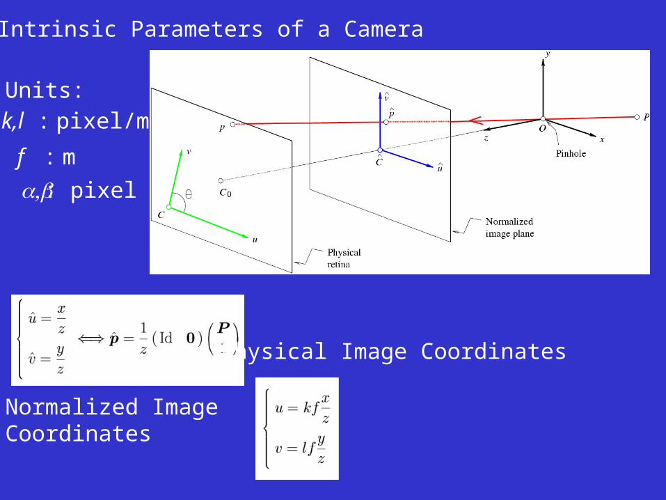
The Intrinsic Parameters of a Camera
Normalized ImageCoordinates
Physical Image Coordinates
Units:
k,l : pixel/m
f : m
: pixel
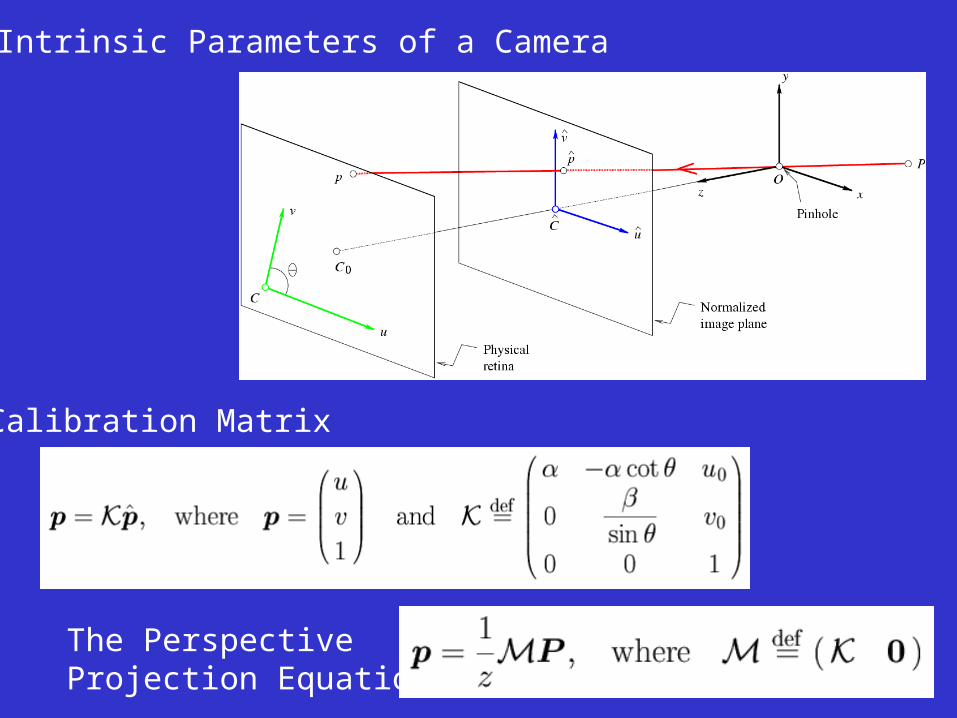
The Intrinsic Parameters of a Camera
Calibration Matrix
The PerspectiveProjection Equation
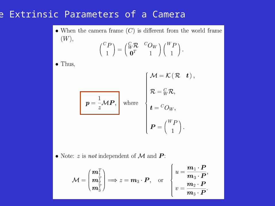
The Extrinsic Parameters of a Camera