ENSEMBLE DE CONTRÔLE ET RÉGULATION POUR …technibel-heatpumps.com/images/items/files/100.pdf ·...
62
Février 2011 10 12 200 - F.GB.I.E.D.P - 00 F GB I E D P MANUEL TECHNIQUE TECHNICAL MANUAL MANUALE TECNICO MANUAL TÉCNICO TECHNISCHES HANDBUCH MANUAL TÉCNICO ENSEMBLE DE CONTRÔLE ET RÉGULATION POUR SYSTÈMES DE CHAUFFAGE / CLIMATISATION AVEC POMPE À CHALEUR INVERTER ET APPOINT ÉLECTRIQUE. APPLICATIONS : - 1 Zone Plancher - 2 Zones Plancher - 1 Zone Unités Terminales - 1 Zone Radiateurs Basse Température (avec ou sans Eau Chaude Sanitaire) - 2 Zones Mixte (Plancher + Unités Terminales) - 2 Zones Mixte (Plancher + Radiateurs Basse Température) CONTROL UNIT FOR HEATING / COOLING SYSTEMS WITH INVERTER HEAT PUMP AND ELECTRIC SUPPORT HEATER. APPLICATIONS: - 1 Floor Zone - 2 Floor Zones - 1 Terminal Units Zone - 1 Low Temperature Radiators Zone (with or without Domestic Hot Water) - 2 Mixed Zones (Floor + Terminal Units) - 2 Mixed Zones (Floor + Low Temperature Radiators) INSIEME DI CONTROLLO E REGOLAZIONE PER SISTEMA DI RISCALDAMENTO / CLIMATIZZAZIONE CON POMPA DI CALORE INVERTER ED INTEGRAZIONE ELETTRICA . APPLICAZIONI : - 1 Zona impianto a Pavimento - 2 Zone impianto a Pavimento - 1 Zona Unità Terminali - 1 Zona Radiatori Bassa Temperatura (con o senza Acqua Calda Sanitaria) - 2 Zone Mista (impianto a Pavimento + Unità Terminali) - 2 Zone Mista (Impianto a Pavimento + Radiatori Bassa Temperatura) CONJUNTO DE CONTROL Y REGULACIÓN PARA SISTEMAS DE CALEFACCIÓN / CLIMATIZACIÓN CON BOMBA DE CALOR INVERTER Y APOYO ELÉCTRICO. APLICACIONES : - 1 Zona Suelo - 2 Zonas Suelo - 1 Zona Unidades Terminales - 1 Zona Radiadores Baja Temperatura (con o sin Agua Caliente Sanitaria) - 2 Zonas Mixto (Suelo + Unidades Terminales) - 2 Zonas Mixto (Suelo + Radiadores Baja Temperatura) KONTROLL- UND REGULIERGERÄT FÜR HEIZUNGS-/KLIMAANLAGEN MIT INVERTER WÄRMEPUMPE UND ELEKTRISCHER ZUSATZHEIZUNG. ANWENDUNGSBEREICHE: - 1 Zone Fußboden - 2 Zonen Fußboden - 1 Zone Innengeräte - 1 Zone Niedrigtemperatur-Heizkörper (mit oder ohne Brauchwarmwasser) - 2 Zonen gemischt (Fußboden + Innengeräte) - 2 Zonen gemischt (Fußboden + Niedertemperatur-Heizkörper) CONJUNTO DE CONTROLO E REGULAÇÃO PARA SISTEMAS DE AQUECIMENTO / CLIMATIZAÇÃO COM BOMBA DE CALOR INVERTER E COMPLEMENTO ELÉCTRICO. APLICAÇÕES : - 1 Zona Soalho - 2 Zonas Soalho - 1 Zona de Unidades Terminais - 1 Zona Radiadores Baixa Temperatura (com ou sem Água Quente Sanitária) - 2 Zonas Mistas (Soalho + Unidades Terminais) - 2 Zonas Mistas (Soalho + Radiadores Baixa Temperatura)
Transcript of ENSEMBLE DE CONTRÔLE ET RÉGULATION POUR …technibel-heatpumps.com/images/items/files/100.pdf ·...

Février 2011 10 12 200 - F.GB.I.E.D.P - 00
F
GB
I
E
D
P
MANUELTECHNIQUE
TECHNICALMANUAL
MANUALE TECNICO
MANUALTÉCNICO
TECHNISCHESHANDBUCH
MANUALTÉCNICO
ENSEMBLE DE CONTRÔLE ET RÉGULATION POUR SYSTÈMES DE CHAUFFAGE / CLIMATISATION AVEC POMPE ÀCHALEUR INVERTER ET APPOINT ÉLECTRIQUE.APPLICATIONS : - 1 Zone Plancher
- 2 Zones Plancher- 1 Zone Unités Terminales- 1 Zone Radiateurs Basse Température (avec ou sans Eau Chaude Sanitaire)- 2 Zones Mixte (Plancher + Unités Terminales)- 2 Zones Mixte (Plancher + Radiateurs Basse Température)
CONTROL UNIT FOR HEATING / COOLING SYSTEMS WITH INVERTER HEAT PUMP AND ELECTRIC SUPPORT HEATER.APPLICATIONS: - 1 Floor Zone
- 2 Floor Zones- 1 Terminal Units Zone- 1 Low Temperature Radiators Zone (with or without Domestic Hot Water)- 2 Mixed Zones (Floor + Terminal Units)- 2 Mixed Zones (Floor + Low Temperature Radiators)
INSIEME DI CONTROLLO E REGOLAZIONE PER SISTEMA DI RISCALDAMENTO / CLIMATIZZAZIONE CON POMPA DICALORE INVERTER ED INTEGRAZIONE ELETTRICA .APPLICAZIONI : - 1 Zona impianto a Pavimento
- 2 Zone impianto a Pavimento- 1 Zona Unità Terminali- 1 Zona Radiatori Bassa Temperatura (con o senza Acqua Calda Sanitaria)- 2 Zone Mista (impianto a Pavimento + Unità Terminali)- 2 Zone Mista (Impianto a Pavimento + Radiatori Bassa Temperatura)
CONJUNTO DE CONTROL Y REGULACIÓN PARA SISTEMAS DE CALEFACCIÓN / CLIMATIZACIÓN CON BOMBA DECALOR INVERTER Y APOYO ELÉCTRICO.APLICACIONES : - 1 Zona Suelo
- 2 Zonas Suelo- 1 Zona Unidades Terminales- 1 Zona Radiadores Baja Temperatura (con o sin Agua Caliente Sanitaria)- 2 Zonas Mixto (Suelo + Unidades Terminales)- 2 Zonas Mixto (Suelo + Radiadores Baja Temperatura)
KONTROLL- UND REGULIERGERÄT FÜR HEIZUNGS-/KLIMAANLAGEN MIT INVERTER WÄRMEPUMPE UNDELEKTRISCHER ZUSATZHEIZUNG.ANWENDUNGSBEREICHE: - 1 Zone Fußboden
- 2 Zonen Fußboden- 1 Zone Innengeräte- 1 Zone Niedrigtemperatur-Heizkörper (mit oder ohne Brauchwarmwasser)- 2 Zonen gemischt (Fußboden + Innengeräte)- 2 Zonen gemischt (Fußboden + Niedertemperatur-Heizkörper)
CONJUNTO DE CONTROLO E REGULAÇÃO PARA SISTEMAS DE AQUECIMENTO / CLIMATIZAÇÃO COM BOMBA DECALOR INVERTER E COMPLEMENTO ELÉCTRICO.APLICAÇÕES : - 1 Zona Soalho
- 2 Zonas Soalho- 1 Zona de Unidades Terminais- 1 Zona Radiadores Baixa Temperatura (com ou sem Água Quente Sanitária)- 2 Zonas Mistas (Soalho + Unidades Terminais)- 2 Zonas Mistas (Soalho + Radiadores Baixa Temperatura)

2
GB
CONTENTS
1 - Precautions . . . . . . . . . . . . . . . . . . . . . . . . . . . . . . . . . . . . . . . . . . . . . . . . . . . . . . . . . . . . . . . 22 - Control operating principle . . . . . . . . . . . . . . . . . . . . . . . . . . . . . . . . . . . . . . . . . . . . . . . . . . . 23 - Presentation of control elements . . . . . . . . . . . . . . . . . . . . . . . . . . . . . . . . . . . . . . . . . . . . . . 44 - 1-zone floor application operation . . . . . . . . . . . . . . . . . . . . . . . . . . . . . . . . . . . . . . . . . . . . . 75 - 2 zones floor application operation . . . . . . . . . . . . . . . . . . . . . . . . . . . . . . . . . . . . . . . . . . . . 156 - Mixed 2 zones floor application operation + terminal units . . . . . . . . . . . . . . . . . . . . . . . . . 237 - Mixed 2 zones floor application operation + low temperature radiators . . . . . . . . . . . . . . 318 - 1-zone terminal units application operation . . . . . . . . . . . . . . . . . . . . . . . . . . . . . . . . . . . . . 399 - 1-zone low temperature radiators application operation . . . . . . . . . . . . . . . . . . . . . . . . . . . 46
10 - Domestic Hot Water (DHW) preparation operation . . . . . . . . . . . . . . . . . . . . . . . . . . . . . . . 5311 - CWC2 control board presentation . . . . . . . . . . . . . . . . . . . . . . . . . . . . . . . . . . . . . . . . . . . . 5612 - Telephone control . . . . . . . . . . . . . . . . . . . . . . . . . . . . . . . . . . . . . . . . . . . . . . . . . . . . . . . . . 58
MARKING
This product, marked with the symbol, complies with the essential requirements of the following Directives:- Low voltage No. 2006/95/EC.- Electromagnetic Compatibility No. 2004/108/EC.
1 - PRECAUTIONS
Before doing any work on the installation, make sure it is switched off and all power supplies locked out.All maintenance / servicing must be performed by qualified personnel, in accordance with current standards and
recognized trade practices.
IMPORTANT
• Consult the installation manuals of the system's various components:- PHRIE Inverter Heat Pump.- 2 zones module (for 2 floor or mixed zone applications) M2Z.- Domestic Hot Water kit KPECS.- System control kit K60D070Z.
• Also consult the user's manual.• This unit has been designed for the applications described in this document and must not be used for any other
purpose.
2 - CONTROL OPERATING PRINCIPLE
• The control assembly enables a complete installation to be controlled from a parameterable system control unit, depending onthe type and conditions of the installation.
• The orders given by the control unit are transmitted (via a system BUS communication line) to the various elements of theinstallation via:
- by the A1 system control board (located in the indoor unit ) which controls:. the heat pump via the CWC2 communication and control board,. the supplementary electric heater built into the heat pump.
- zone boards, if any, which control the 2-zone modules.• The control unit's rotating knob is used to select the desired operating mode:
- Heating: The heat pump and any supplementary electric heater are controlled in relation to a setpoint resulting from the watertemperature calculated according to a water rule (according to the outside temperature).
- Cooling (for applications compatible with this mode): The heat pump is controlled according to a fixed set point (based on the ambient temperature for floor applications).

3
GB
Control flow diagram
System control unit
System control board
A1
Circulator
Electricsupplementary
heating
Water temperature(return)
Water temperature(outgoing)
System communication line (BUS)
Power board A3
Control board CWC2A2
PHRIE heat pump
Circulator control
Compressor
Fans
Expansion valve
Cycle inversionvalve
DC BUS + filter
InverterPowerModule
Water flowdetection
Outdoor airtemperature sensor
C1 Temperature
C2 Temperature
Dischargetemperature TD
Suctiontemperature TS
Outsidetemperature TO
Water temperature(return)
Water temperature(outgoing)
Liquid linetemperature E1
Exchangerpressure E2
TW2 TW1 E1 EP2
To 2 zones moduleor DHW tank(if any)
K60D070Z Control kit

4
GB
3 - PRESENTATION OF CONTROL ELEMENTS
3.1 - SYSTEM REMOTE CONTROL UNIT - Included with control kit
Rotary function selection knob (9 positions, left to right):
- Cooling: Operation in cooling mode for reversible applicationsor- DHW (domestic hot water) only in summer: for the 1-zone radiators
application only (non reversible )
- Heating, anti-freeze: Anti-freeze mode operation
- Heating, ECO: Heating mode operation with ECO setting
- Heating, Auto: Heating mode operation with hourly programming
- Heating: Heating mode operation with Comfort setting
- Stop
- Time setting
- Prog. Z1: Zone 1 program control (hourly / weekly)
- Prog. Z2: Zone 2 program control (hourly / weekly) if activated
Push-button for setpoint and parameter modification
Push-button for setpoint and parameter modification
“Z/OK” push-button Display selection zone 1 / zone 2 / outside temperature and validation
Liquid crystal display (LCD)
Micro-switch to activate a 2nd heating zone using electric convectors (for 1 zone floor or 1 zone terminal unitapplications).This micro-switch is located on the back of the unit's printed circuit board. Remove the base to gain access to this switch.
Ambient temperature sensor
1
6
2
3
4
5
7
DHW cycle (domestic hot water)in progress if function activated
Heating with supplementaryheating only (following aheat pump fault)
Day of the week
or parameter level
Override in progress
Hourly programming
Zone 1 display
Zone 2 display (if activated)
Supplementary heating ON
Outside temperaturedisplay
Telephone overrideactivated
Comfort / ECO / Anti-freeze indication
• When off, the display indicates “OFF”.• When in operation, the normal reference display indicates:
- the setpoint temperature of zone 1 (for a floor zone),- the current setting with the hourly program bar graph:
= Comfort
= ECO
No indication = Anti-freeze (prolonged absence)- current day.
Note: In the case of a 2nd zone with electric convectors, radiators, terminal units, or in the case of a terminal unit zone,there is no centralized set point or ambient temperature measurement. The display indicates “HEAT” (or “COOL”in cooling mode for the terminal units).
5
GB
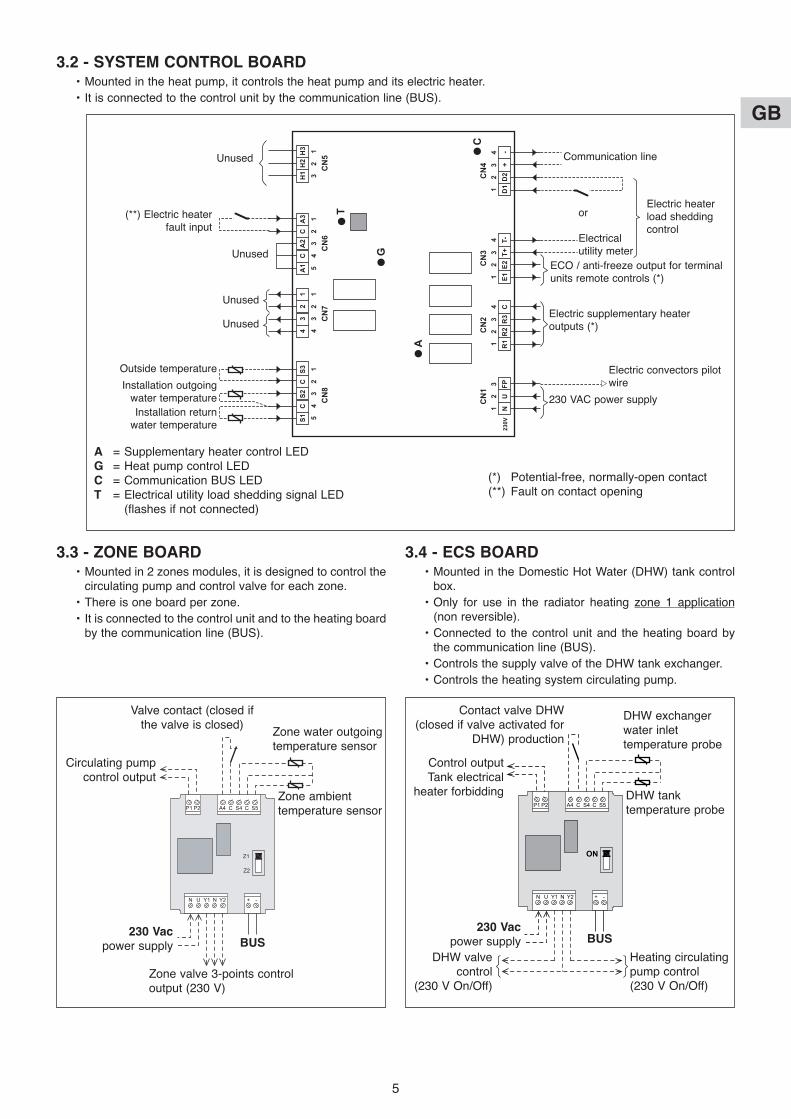
3.3 - ZONE BOARD• Mounted in 2 zones modules, it is designed to control the
circulating pump and control valve for each zone.• There is one board per zone.• It is connected to the control unit and to the heating board
by the communication line (BUS).
3.4 - ECS BOARD• Mounted in the Domestic Hot Water (DHW) tank control
box.• Only for use in the radiator heating zone 1 application
(non reversible).• Connected to the control unit and the heating board by
the communication line (BUS).• Controls the supply valve of the DHW tank exchanger.• Controls the heating system circulating pump.
BUS
Zone ambienttemperature sensor
Zone valve 3-points controloutput (230 V)
Circulating pumpcontrol output
Valve contact (closed ifthe valve is closed)
Zone water outgoingtemperature sensor
230 Vacpower supply
DHW tanktemperature probe
Control output Tank electrical
heater forbidding
Contact valve DHW(closed if valve activated for
DHW) production
DHW exchangerwater inlettemperature probe
230 Vacpower supply BUS
DHW valvecontrol
(230 V On/Off)
Heating circulatingpump control(230 V On/Off)
3.2 - SYSTEM CONTROL BOARD• Mounted in the heat pump, it controls the heat pump and its electric heater.• It is connected to the control unit by the communication line (BUS).
12
CN
1
A
G
T
C
230V
CN
2C
N3
CN
4
CN
8C
N7
CN
6C
N5
3
54
32
14
32
14
53
21
32
1
NU
FPR
1R
2R
3C
E1E2
T+
H1
A1
CA
2C
43
21
S1C
S2C
S3A
3H
2H
3
T-D
1D
2+
-1
23
41
23
41
23
4 Communication line
Electric heater load shedding control
or
Electricalutility meter
ECO / anti-freeze output for terminalunits remote controls (*)
Electric supplementary heateroutputs (*)
Electric convectors pilotwire
230 VAC power supply
Unused
(**) Electric heater fault input
Outside temperature
Installation outgoing water temperatureInstallation return
water temperature
(*) Potential-free, normally-open contact(**) Fault on contact opening
A = Supplementary heater control LEDG = Heat pump control LEDC = Communication BUS LEDT = Electrical utility load shedding signal LED
(flashes if not connected)
Unused
Unused
Unused
6
GB
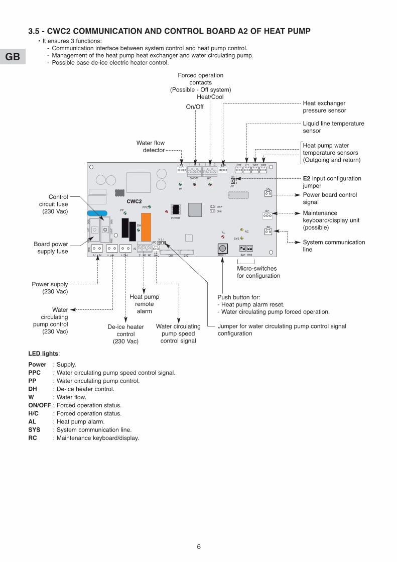
Jumper for water circulating pump control signalconfiguration
LED lights:
Power : Supply.PPC : Water circulating pump speed control signal.PP : Water circulating pump control.DH : De-ice heater control.W : Water flow.ON/OFF : Forced operation status.H/C : Forced operation status.AL : Heat pump alarm.SYS : System communication line.RC : Maintenance keyboard/display.
3.5 - CWC2 COMMUNICATION AND CONTROL BOARD A2 OF HEAT PUMP• It ensures 3 functions:
- Communication interface between system control and heat pump control.- Management of the heat pump heat exchanger and water circulating pump.- Possible base de-ice electric heater control.
NN
OC
RC
SC
CWC2
PPCDHPPU N
TW2TW1E1E2TFS E2P
PP
DH
PPC
W
AL
SYS
RC
123
DISP
CHK
123
POWER
Control circuit fuse (230 Vac)
Board powersupply fuse
Power supply(230 Vac)
Watercirculating
pump control(230 Vac)
Water flowdetector
On/Off
Heat/CoolHeat exchangerpressure sensor
Forced operationcontacts
(Possible - Off system)
Liquid line temperaturesensor
Heat pump watertemperature sensors(Outgoing and return)
E2 input configurationjumper
Power board controlsignal
Maintenancekeyboard/display unit(possible)
System communicationline
Micro-switches for configuration
Push button for:- Heat pump alarm reset.- Water circulating pump forced operation.
De-ice heatercontrol
(230 Vac)
Heat pumpremotealarm
Water circulatingpump speedcontrol signal

7
GB
• The operating modes are selected using the rotary knob on the front of the control unit (see chapter 3.1 and user's manual).
4.1 - HEATING MODE4.1.1 - HEATING OPERATING DIAGRAM
4 - 1-ZONE FLOOR APPLICATION OPERATION
X
2K2K2K
Y
An outside temperature Xdetermines a resulting watertemperature setpoint Y.
The parameters determiningthis water rule can be set bythe installer (see the table inparagraph 4.6).
The resulting setpoint isdisplayed at parameter 04.It can be corrected as requireddepending on the ambienttemperature of the zone.
4.1.2 - “COMFORT” HEATING MODE • Temperature setpoint
- The heat pump can operate only if the outside temperature is less than the non-heating temperature.- The heat pump is controlled via the heating board according to a resulting setpoint of the water temperature
(control on the installation return) calculated according to an adjustable water rule determined by:- the non-heating temperature (parameter 23),- the regional minimum temperature (parameter 21),- the minimum temperature of the water circuit (parameter 32),- the maximum temperature of the water circuit (parameter 30).
Heat pump circulator control
Temperature (°C) Temperature (°C)-20 97 120 30 8 058-15 72 980 35 6 532-10 55 340 40 5 326-5 42 340 45 4 3680 32 660 50 3 5025 25 400 55 2 936
10 19 900 60 2 48815 15 710 65 2 08220 12 490 70 1 75125 10 000
Ohmic value (Ohm) Ohmic value (Ohm)
3.6 - SYSTEM CONTROL TEMPERATURE SENSORS• Type CTN 10 KΩ at 25°C.
3.7 - POWER FAILURE• In case of power failure, the parameters and settings are maintained. If the power outage exceeds 6 hours, the time setting
will have to be corrected.
Water temperature setpoint
Outside temperature
Water temperature resultingsetpoint slope
Max. water temperature(parameter 30)
Min. water temperature(parameter 32)
Heat pump shutdownthreshold
(parameter 20)
Regional min. temperature(parameter 21)
Supplementary heatingauthorization threshold
(parameter 22)
No heatingsetpoint(parameter 23)
Heat pump authorization
Supplementary heatingauthorization
If heat pump alarm or if heat pumpprohibited due to excessively cold water

8
GB
The resulting setpoint calculated in this manner can be corrected by the temperature of the zone:A difference of +/- 1 degree of ambient temperature in relation to the heating setpoint temperature of the zone(adjustable from 15 to 25°C) causes the resulting setpoint (water temperature) to decrease or increase of 2 degrees,respectively. However, this variation cannot exceed +/- 5 degrees.The calculated resulting set point is displayed at parameter 04.Note:The set point value sent to the heat pump can be clipped to the maximum value given in parameter 43.
• Supplementary electric heating- The heating elements are actuated if the heat pump is not
able to maintain the water return temperature at thecalculated value. The supplementary heating by electricalheating elements is staged (2 stages). Tiering is managed bya 10-minute time delay for the 2nd.
- Caution:During normal operation, the supplementary heating isauthorized only if the outside temperature falls below theauthorization threshold (parameter 22) corresponding to theinstallation's equilibrium temperature and the absence of aload shedding signal. However, if can be authorized forgreater temperatures if the heat pump is experiencing analarm or if heat pump operation is prohibited by a safetydevice (and even if a load shedding signal is present).Supplementary heating is prohibited if it is experiencing analarm.
• Heat pump operating safety features in heating mode- A safety device on the water temperature (installation return) prohibits heat pump operation if this temperature is
below the thermodynamic heating authorization threshold (parameter 36). In this case, only supplementary heatingis authorized to raise the water temperature and allow the heat pump to operate, regardless of the outsidetemperature (load shedding is thus inoperative). The activation of this safety feature is indicated by the flashing ofthe display.
- Heat pump operation is prohibited if the outside temperature is below the shut-off threshold (parameter 20). Onlysupplementary heating is authorized (load shedding is thus inoperative).
• Limitation on ambient temperature- In heating mode, operation of the heat pump and the electric heater (if any) is prohibited if the ambient temperature
of the zone exceeds the ambient set point temperature by 3.5°C. The operation is authorized once again if theambient temperature falls to the ambient set point value.
• Control of the heat pump's circulator- The heating mode, activated if the outside temperature is less than the non-heating temperature.- If the circulator is off:
- an “anti-sticking” function starts the circulator for 5 seconds every 24 hours.- The “frost protection” function starts the circulator if the outside temperature is below 0°C.
See details in paragraph 11.
4.1.3 - “ECONOMY” HEATING MODE • The switch to “ECO” mode lowers the ambient temperature setpoint by a value than can be adjusted from 1 to 4 K
(parameter 24).• It can only be activated in heating mode (inactive in cooling mode).• Switching from “Comfort” to “ECO” is accomplished either by hourly programming, weekly programming by zone or by
actuating the rotary knob for the entire installation.• In the case of hourly programming, the user can activate a temporary override (1 hour + periods of 1 hour during the
current day) per zone.
4.1.4 - “ANTI-FREEZE” HEATING MODE (prolonged absence) • Selection is made using the rotary knob on the control unit
for the entire installation.• The water temperature resulting setpoint passes to an
adjustable value (parameter 29 is factory-set at 25°C). Heating (heat pump + supplementary heating, if any) isactuated depending on the ambient temperature setpointadjustable (parameter 25 set to 12°C in the factory).
Watertemperature
Supplementaryheating command
Resulting setpoint
Parameter 26
Parameter 27
Ambient temperature
Heating command
Anti-freeze mode ambient temperature setpoint

9
GB
4.2 - COOLING MODE• Selection is made using the rotary knob on the control unit.• Temperature setpoint
- The heat pump operates with the water temperature setpoint (installation return) given in parameter 42. It isrecommended if the ambient temperature is greater than thecooling setpoint (adjustable from 20 to 30°C).
• Heat pump operating safety features in cooling mode- Heat pump operation is prohibited if the installation return water temperature is above a threshold (parameter 35). The
activation of this safety feature is indicated by the flashing of the display.- An “anti-condensation” device on the installation's outgoing temperature prohibits heat pump operation if this
temperature is below 15°C. This device is designed to limit the risks of condensation.
• Control of the heat pump's circulator- In cooling mode, actuated as soon as the mode is selected.- If the circulator is off, an “anti-sticking” function starts the circulator for 5 seconds every 24 hours. See details in
paragraph 11.
• Cooling mode restriction- The cooling mode can be restricted by setting parameter 71 to “0”.- At this time, selecting “COOL” on the control unit will cause shutdown “OFF”.
4.3 - ELECTRIC HEATER FORCING FOR MAINTENANCE- See details in Service Manual.- When installation system control is “OFF”, it is possible to activate, for a limited time, the electric support heater.- This sequence can only be performed by a qualified technician during maintenance operation.
The sequence is controlled by mean of parameters 40 and 41 after being sure that water circulator is forced.
4.4 - 2nd ZONE - ELECTRIC CONVECTORS• A 2nd zone equipped with electric convectors can also be managed (Max. number = 20). These appliances must be equipped
with an electronic thermostat (not included) able to receive signals via a 230 VAC pilot wire (standard GIFAM 4).• The 2nd zone is activated by setting the micro-switch in the back of the control unit to the “ON” position.
- In “Comfort”, “ECO” or “Anti-freeze” heating modes, the corresponding signals are transmitted to the 2nd zone.- In cooling mode and in the Stop position, the shut-down signal is transmitted to the 2nd zone.- In heating mode with hourly programming, the “Comfort” or “ECO” signals are transmitted to the 2nd zone according
to the corresponding hourly programming.Note: In case of load shedding, a shut-down signal is transmitted to the 2nd zone.
- In heating mode, the display unit indicates for the zone 2 “HEAT”.
4.5 - MISCELLANEOUS• Mode changes using the rotary knob (Heating / Cooling / Anti-freeze / Stop) are delayed 10 seconds in order to filter
inappropriate actions. However, the “Time Setting” and “Hourly Programming” positions do not have the time delayfeature.
• The authorization thresholds on the water temperature are cut-off values with a differential of 1 K for the reset.
Ambient temperature
Heat pump command
Cooling ambient temperature setpoint

10
GB
4.6 - PARAMETERS• Access:
- 2 access levels:- Level 1, read only, with direct access for parameters 1 to 19,- Level 2, “technical level” accessible by password “see last page”.
This level is entered via parameter 20, although all parameters are accessible.
Procedure:
1°) Simultaneously press and hold the buttons and for 5 seconds, until thescreen displays PArA.
2°) Select the User menu = Level 1 or Installer = Level 2 using the and buttons.
3°)* To access level 1, press “Z/OK.The display indicates the firstparameter “P01”.
Press the or keys to shift fromone parameter to another.To know the value of the parameter,press “Z/OK”.To redisplay the value of theparameter, press “Z/OK” again.
3Bis°)* To access level 2, press “Z/OK”.
The display shows “ ”.
Enter the password digit by digit, by selecting the desired digit using the or buttons and by confirming with“Z/OK”. Once the password is entered, the display then indicates “P20” which is the first parameter of this level.
To display the value of a parameter, select it using the or keys and press “Z/OK”.
To modify this parameter, if needed, press keys or .To redisplay the value of the parameter, press “Z/OK” again.
4°) To exit the parameterisation procedure, press and hold “Z/OK”.In all cases (except the flow-rate calculation), the display returns to normal automatically after a few minutes ofinactivity.The parameters can be accessed and modified both in operation and when shut down, except for those forinstallation configuration and default parameterisation which can only be accessed and modified when theinstallation is shut down.Note: The flashing parameter values are those that can be modified. Otherwise, the display remains steady.
• Configuration of installation type
IMPORTANT: THE FOLLOWING ELEMENTS MUST BE CARRIED OUT EACH TIME THE INSTALLATION ISPLACED INTO SERVICE
- For 1 Floor Zone application, parameter 70 must be set to “1”.- Procedure:
1) Set the rotary knob on the control unit to the “Stop” position.2) Go to parameter 70. Press the “Z/OK” button; the value of the parameter is displayed. This value may be read or
modified using the and buttons if the system is in the “Stop” position. If parameters are modified, aninitialisation process is launched automatically (the “init” message is displayed). When initialisation is completed,the display returns to parameter 70.Note: If this parameter is set in other than the “Stop” position, the “STOP” message flashes and the parametercannot be modified.
3) Once the configuration parameters have been verified, disconnect and re-establish the system's power supply toreset the control system.
1: User2: Installer
Access to the 1st parameter (P01) Display of the parametervalue

11
GB
Caution: At the end of the operation, forcing must be deactivated (by returning parameter 67 to “0”) beforerestarting the installation.
• Default configuration- This enables the default values (see list) of all parameters to be reset according to the type of installation.- Procedure:
- Set the rotary knob on the control unit to the “Stop” position.- Go to parameter 60. Press the “Z/OK” button; the “init” message is displayed.
Note: If this parameter is set in other than the “Stop” position, the word “STOP” flashes and the configuration cannot belaunched.
- Press and hold the “Z/OK” button for 5 seconds to launch the default configuration. The “init” message flashes.When initialisation is completed, the display returns to parameter 60.
• Calibration of temperature sensors (“Offset”)- The value displayed by certain sensors may be adjusted. To do this, move to the corresponding parameter and enter
the desired value (+/- 3 degrees maximum).• Heat pump control forcing
- For maintenance operations only, when the system is “OFF”, it is possible to force heat pump control by setting toparameter 67 to “1”. The heat pump operates in heating mode at the set point given at parameter 43.
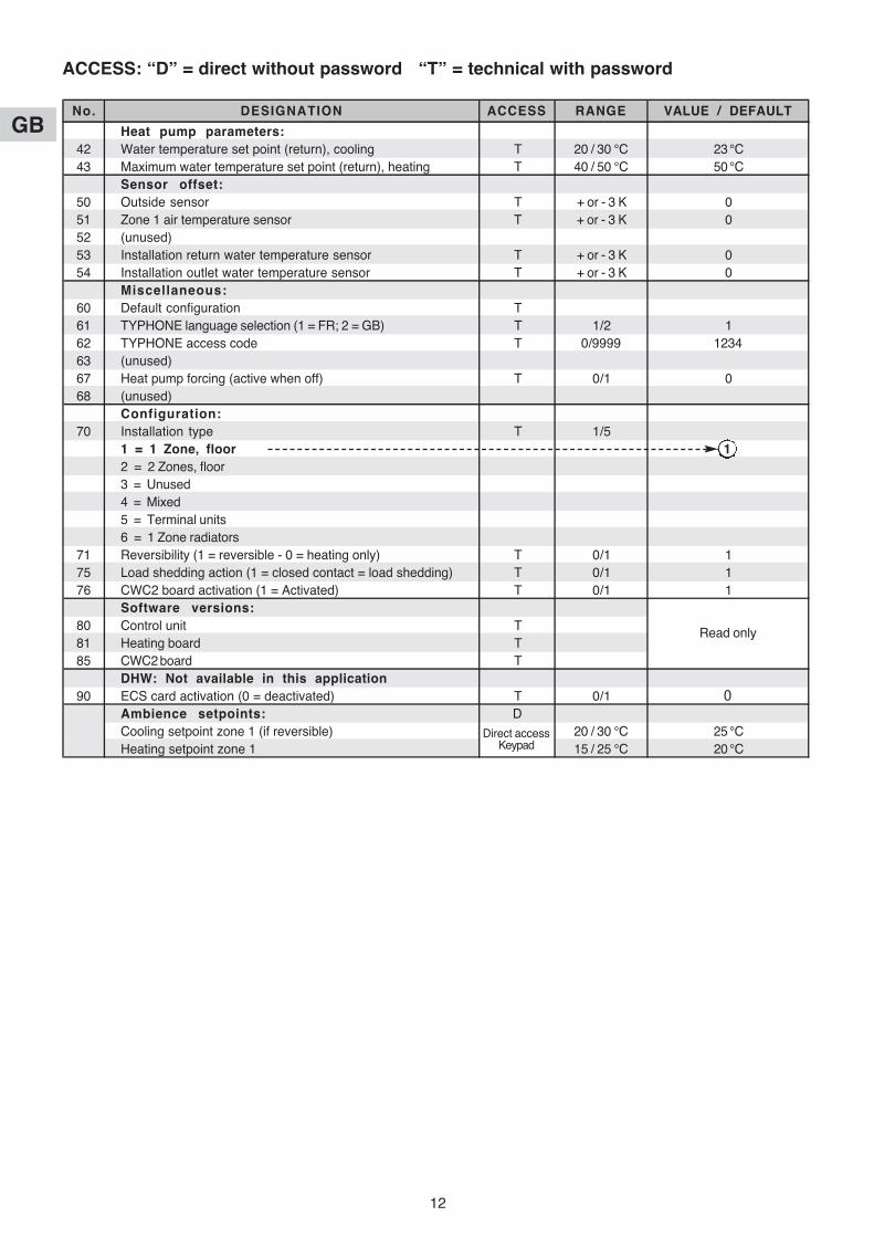
ACCESS: “D” = direct without password “T” = technical with password
No. DESIGNATION ACCESS RANGE VALUE / DEFAULT
Status:01 Outside temperature D - 40 / + 90 °C02 Installation return water temperature D - 40 / + 90 °C03 Installation outgoing water temperature D - 40 / + 90 °C04 Water temperature resulting setpoint D05 (unused)06 (unused)07 (unused)08 Ambient temperature, zone 1 D - 40 / + 90 °C09 (unused)10 Heat pump outlet status (0 = off; 1 = authorised) D 0/111 Operating mode output status (1 = heating; 0 = cooling) D 0/112 Outlet status, supp. 1 D 0/113 Outlet status, supp. 2 D 0/114 Outlet status, supp. 3 D 0/1
Air temperature settings:20 Heat pump shut-down threshold T - 20 / 0 °C - 16 °C21 Regional min. temperature T - 20 / 5 °C - 7 °C22 Supplementary authorization threshold T - 5 / 20 °C 7 °C23 No heating threshold T 10 / 25 °C 17 °C24 Lowering of ECO temperature (ambience) T 1 / 4 K 2 K25 Ambient temperature set point at anti-freeze T 8 / 18 °C 12 °C
Water temperature settings:26 Supplementary heating control hysteresis T 2 / P27 K 2 K27 Supplementary heating control lag T P26 / 6 K 3.5 K28 Heat pump control hysteresis - unused T 1 / 4 K 2.5 K29 Water temperature setpoint in "anti-freeze" mode T 20 / 35 °C 25 °C30 Heating water max. temperature (installation return) T 25 / 40 °C 35 °C31 (unused)32 Heating water min. temperature (installation return) T 20 / 30 °C 20 °C33 (unused)34 (unused)35 Cooling authorization threshold (installation return) T 25 / 50 °C 30 °C36 Thermodynamic heating authorization threshold (installation return) T 10 / 20 °C 15 °C37 Water outlet temperature max. alarm threshold T 60 / 90 °C 70 °C
Electric heater forcing (for maintenance only):40 Total electric heating capacity T 1 / 30 kW 6 kW41 Launch of the sequence T
Read only
12
GB Heat pump parameters:42 Water temperature set point (return), cooling T 20 / 30 °C 23 °C43 Maximum water temperature set point (return), heating T 40 / 50 °C 50 °C
Sensor offset:50 Outside sensor T + or - 3 K 051 Zone 1 air temperature sensor T + or - 3 K 052 (unused)53 Installation return water temperature sensor T + or - 3 K 054 Installation outlet water temperature sensor T + or - 3 K 0
Miscellaneous:60 Default configuration T61 TYPHONE language selection (1 = FR; 2 = GB) T 1/2 162 TYPHONE access code T 0/9999 123463 (unused)67 Heat pump forcing (active when off) T 0/1 068 (unused)
Configuration:70 Installation type T 1/5
1 = 1 Zone, floor 12 = 2 Zones, floor3 = Unused4 = Mixed5 = Terminal units6 = 1 Zone radiators
71 Reversibility (1 = reversible - 0 = heating only) T 0/1 175 Load shedding action (1 = closed contact = load shedding) T 0/1 176 CWC2 board activation (1 = Activated) T 0/1 1
Software versions:80 Control unit T81 Heating board T85 CWC2 board T
DHW: Not available in this application90 ECS card activation (0 = deactivated) T 0/1 0
Ambience setpoints: DCooling setpoint zone 1 (if reversible) 20 / 30 °C 25 °CHeating setpoint zone 1 15 / 25 °C 20 °C
Direct accessKeypad
Read only
No. DESIGNATION ACCESS RANGE VALUE / DEFAULT
ACCESS: “D” = direct without password “T” = technical with password
13
GB
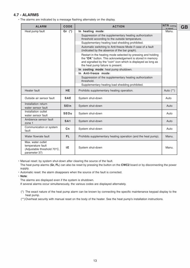
4.7 - ALARMS• The alarms are indicated by a message flashing alternately on the display.
• Manual reset: by system shut-down after clearing the source of the fault.The heat pump alarms (Gr, FL) can also be reset by pressing the button on the CWC2 board or by disconnecting the powersupply.
• Automatic reset: the alarm disappears when the source of the fault is corrected.• Note:
The alarms are displayed even if the system is shutdown.If several alarms occur simultaneously, the various codes are displayed alternately.
(*) The exact nature of the heat pump alarm can be known by connecting the specific maintenance keypad display to theheat pump.
(**)Overheat security with manual reset on the body of the heater. See the heat pump's installation instructions.
ALARM CODE ACTION NTR (nothing
to report)
Heat pump fault Gr (*) In heating mode: Manu.
Supplementary heating load shedding prohibited.
In cooling mode: heat pump shutdown.In Anti-freeze mode:
Supplementary heating load shedding prohibited.
Heater fault HE Prohibits supplementary heating operation. Auto (**)
Installation returnwater sensor faultInstallation outletwater sensor fault
Water flowrate fault FL Prohibits supplementary heating operation (and the heat pump). Manu.
SEIn
Manu.
Suppression of the supplementary heating authorizationthreshold.
Max. water outlettemperature fault(Adjustable threshold 70°C,parameter 37)
tE System shut-down
SA1 System shut-down
System shut-down
SEOu System shut-down
Auto
Auto
Auto
Auto
Auto
Suppression of the supplementary heating authorizationthreshold according to the outside temperature.
Automatic switching to Anti-freeze Mode if case of a fault(indicated by the absence of the bar graph).
Restart in the heating mode selected by pressing and holdingthe "OK" button. This acknowledgement is stored in memoryand signalled by the "coin" icon which is displayed as long asthe heat pump failure is present.
Communication or systemfault
Cn System shut-down
Outside air sensor fault SAE System shut-down
Ambience sensor faultzone 1

14
GB
4.8 - HYDRAULIC SCHEMATIC DIAGRAM
Out
door
sen
sor
(sup
plie
d w
ith s
yste
mco
ntro
l kit
K60
D07
0Z)
Sys
tem
con
trol
kit
K60
D07
0Z(S
uppl
ied
in a
cces
sory
)
PH
RIE
Ele
ctric
heat
er
In L
ine
Str
aine
r(s
uppl
ied
with
PH
RIE
)
Co
olin
g
Installation is to be performed in compliance withestablished trade practices and current standards.
Note:For easy understanding, all isolation valves are notindicated on this drawing.
See accessories table.
Sys
tem
boar
d
Wat
erou
tlet
sens
ors
Wat
er in
let
sens
ors
Com
mun
icat
ion
line
Hea
tin
g
Un
der
Flo
or
Pum
p

15
GB• The operating modes are selected using the rotary knob on the front of the control unit (see chapter 3.1 and user's manual).
5.1 - HEATING MODE5.1.1 - HEATING OPERATING DIAGRAM
5 - 2 ZONES FLOOR APPLICATION OPERATION
X
Y1
Y2Z1
Z2
2K2K2K
A water rule is determined foreach zone.
An outside temperature Xdetermines a water temperatureresulting setpoint Y1 for zone 1and Y2 for zone 2.
The parameters determining thiswater rule can be set by theinstaller (see the table inparagraph 5.7).
The resulting setpoint for zone 1 isdisplayed at parameter 04.
The resulting setpoint for zone 2 isdisplayed at parameter 05.
Each resulting setpoint can becorrected as required dependingon the ambient temperature of thezone.
The heat pump is controlledaccording to the highest resultingsetpoint.
The control valve of each zone iscontrolled according to theresulting setpoint of the zone.
5.1.2 - “COMFORT” HEATING MODE • Water temperature setpoint
- The circulating pump of each zone is actuated and the control valve activated if the outside temperature is less thanthe non-heating temperature.
- The heat pump can operate only if the outside temperature is less than the non-heating temperature.- A water rule is determined for each zone according to the settings that are specific to the zone. A resulting setpoint
of the water temperature is calculated according to the outside temperature and the ambient temperature of the zone.The control valve is controlled by the zone board according to this resulting setpoint and the water temperature readby the sensor placed on the outlet of the zone considered.
- The heat pump and the supplementary heating are thus controlled (in relation to the installation's return temperature)according to the highest resulting setpoint of the 2 circuits.Note:The set point value sent to the heat pump can be clipped to the maximum value given in parameter 43.
For each zone, the water rule is determined by:- the non-heating temperature (parameter 23),- the regional minimum temperature (parameter 21),- the minimum temperature of the water circuit (parameters 32 for zone 1, 33 for zone 2),- the maximum temperature of the water circuit (parameters 30 for zone 1, 31 for zone 2).
The resulting setpoint calculated in this manner can be corrected by the ambient temperature of the zone:A difference of +/- 1 degree of ambient temperature in relation to the heating setpoint temperature of the zone(adjustable from 15 to 25°C) causes the resulting setpoint (water temperature) to decrease or increase of 2 degrees,respectively. However, this variation cannot exceed +/- 5 degrees.The resulting zone 1 and zone 2 set points are displayed at parameters 04 and 05.
Activation Zone 1 (pump + valve)
Heat pump circulator control
Activation Zone 2 (pump + valve)
Water temperature setpoint
Outside temperature
Water temperature resultingsetpoint slope in Zone 1
Max. water temp. Z1 (parameter 30)
Min. water temp. (parameter 32)
Heat pump shutdownthreshold
(parameter 20)
Regional min. temperature(parameter 21)
Supplementary heatingauthorization threshold
(parameter 22)
No heating setpoint(parameter 23)
Heat pump authorization
Supplementary heatingauthorization
If heat pump alarm or if heat pumpprohibited due to excessively cold water
Water temperature resultingsetpoint slope in Zone 2
Min. water temp. (parameter 33)
Max. water temp. Z2 (parameter 31)

16
GB
• Control of the heat pump's circulator- The heating mode, activated if the outside temperature is less than the non-heating temperature.- If the circulator is off:
- an “anti-sticking” function starts the circulator for 5 seconds every 24 hours.- The “frost protection” function starts the circulator if the outside temperature is below 0°C.
See details in paragraph 11.
• Supplementary electric heating- The heating elements are actuated if the heat pump is not able
to maintain the water return temperature at the calculated value.The supplementary heating by electrical heating elements isstaged (2 stages). Tiering is managed by a 10 minute time delayfor the 2nd.
- Caution:During normal operation, the supplementary heating isauthorized only if the outside temperature falls below theauthorization threshold (parameter 22) corresponding to theinstallation's equilibrium temperature and the absence of a loadshedding signal. However, if can be authorized for greatertemperatures if the heat pump is experiencing an alarm or ifheat pump operation is prohibited by a safety device (and evenif a load shedding signal is present).Supplementary heating is prohibited if it is experiencing an alarm.
• Heat pump operating safety features in heating mode- A safety device on the water temperature (installation return) prohibits heat pump operation if this temperature is
below the thermodynamic heating authorization threshold (parameter 36). In this case, only supplementary heatingis authorized to raise the water temperature and allow the heat pump to operate, regardless of the outsidetemperature (load shedding is thus inoperative). The activation of this safety feature is indicated by the flashing ofthe display.
- Heat pump operation is prohibited if the outside temperature is below the shut-off threshold (parameter 20). Onlysupplementary heating is authorized (load shedding is thus inoperative).
5.1.3 - “ECONOMY” HEATING MODE • The switch to “ECO” mode lowers the ambient temperature setpoint of the zone by a value than can be adjusted from
1 to 4 K (parameter 24).• It can only be activated in heating mode (inactive in cooling mode).• Switching from “Comfort” to “ECO” is accomplished either by hourly programming, weekly programming by zone or by
actuating the rotary knob for the 2 zones.• In the case of hourly programming, the user can activate a temporary override (1 hour + periods of 1 hour during the
current day) per zone.
5.1.4 - “ANTI-FREEZE” HEATING MODE (prolonged absence) • Selection for the 2 zones is made using the rotary knob on the control unit.• The water temperature resulting setpoint passes to an adjustable value (parameter 29 is factory-set at 25°C) identical
for the 2 zones.Each zone can only be activated (circulating pump andcontrol valve) if the ambient temperature of the zone is lessthan an adjustable set point (parameter 25 set to 12°C in thefactory).If ambient temperature in the zone rises above this set point,the circulating pump stops (after a 1 minute delay) and thevalve is closed.
• In order to guarantee a minimal thermal load, the heatpump can only operate if at least one zone is activated(circulating pump in operation and valve open).
5.2 - COOLING MODE• Selection for the 2 zones is made using the rotary knob on the
control unit.• The heat pump operates with the water temperature set point
(installation return) given in parameter 42.• Each zone can only be activated (circulating pump and control
valve) if the ambient temperature of the zone is greater than thezone's setpoint. At this moment, the zone valve adjusts thewater temperature of the floor outgoing line according to anadjustable setpoint (parameter 34 is factory-set at 20°C).If the ambient temperature of the zone drops below this threshold, the circulating pump stops (after a 1 minute delay) andthe valve is closed.
• In order to guarantee a minimal thermal load, the heat pump can only operate if at least one zone is activated(circulating pump in operation and valve open).
Watertemperature
Supplementaryheating command
Resulting setpoint
Ambient temperature
Zone activation
Anti-freeze mode ambient temperature setpoint
Ambient temperature
Zone activation
Cooling ambient temperature setpoint
Parameter 26
Parameter 27

17
GB
• Heat pump operating safety features in cooling mode- Heat pump operation is prohibited if the installation return water temperature is above a threshold (parameter 35). The
activation of this safety feature is indicated by the flashing of the display.- An “anti-condensation” device on the installation's outgoing temperature prohibits heat pump operation if this
temperature is below 15°C.• Control of the heat pump's circulator
- In cooling mode, actuated as soon as the mode is selected.- If the circulator is off, an “anti-sticking” function starts the circulator for 5 seconds every 24 hours. See details in
paragraph 11.
• Cooling mode restriction- The cooling mode can be restricted by setting parameter 71 to “0”.- At this time, selecting “COOL” on the control unit will cause shutdown “OFF”.
5.3 - ELECTRIC HEATER FORCING FOR MAINTENANCE- See details in Service Manual.- When installation system control is “OFF”, it is possible to activate, for a limited time, the electric support heater.- This sequence can only be performed by a qualified technician during maintenance operation.
The sequence is controlled by mean of parameters 40 and 41 after being sure that water circulator is forced andzones activated.
5.4 - HEAT PUMP CONTROL• In order to guarantee a minimal thermal load, the heat pump can only operate if at least one zone is activated
(circulating pump in operation and valve open).• Forcing: for maintenance operations only, when the system is “OFF”, it is possible to force heat pump control by setting to
parameter 67 to “1”.The heat pump operates in heating mode at the set point given at parameter 43.
5.5 - CONTROL OF ZONE OUTGOING LINES• Managed by the zone board.
5.5.1 - VALVES• Valves operating in mix.• “3-point” motor (230 VAC) with proportional chrono control:
- Time base = Valve action time (parameter 63)10
- Percentage of the control time = Difference (setpoint / water outlet temperature)Proportional strip (parameter 38)
This percentage is displayed at parameter 17 for zone 1 and 18 for zone 2,(“+” sign = open, “–” sign = closed)In the neutral zone (parameter 39), the valve is not controlled.
• The valves are equipped with a limit switch which detect valve closure (contact closed = valve closed).
5.5.2 - CIRCULATING PUMPS• Pump shutdown is delayed 1 minute.
Caution: At the end of the operation, forcing must be deactivated (by returning parameter 67 to “0”) beforerestarting the installation.

18
GB
5.6 - MISCELLANEOUS• Mode changes using the rotary knob (Heating / Cooling / Anti-freeze / Stop) are delayed 10 seconds in order to filter
inappropriate actions. However, the “Time Setting” and “Hourly Programming” positions do not have the time delayfeature.
• The authorization thresholds on the water temperature are cut-off values with a differential of 1 K for the reset.
5.7 - PARAMETERS• Access:
- 2 access levels:- Level 1, read only, with direct access for parameters 1 to 19,- Level 2, “technical level” accessible by password “see last page”.
This level is entered via parameter 20, although all parameters are accessible.
Procedure:
1°) Simultaneously press and hold the buttons and for 5 seconds, until thescreen displays PArA.
2°) Select the User menu = Level 1 or Installer = Level 2 using the and buttons.
3°)* To access level 1, press “Z/OK.The display indicates the firstparameter “P01”.
Press the or keys to shift fromone parameter to another.To know the value of the parameter,press “Z/OK”.To redisplay the value of theparameter, press “Z/OK” again.
3Bis°)* To access level 2, press “Z/OK”.
The display shows “ ”.
Enter the password digit by digit, by selecting the desired digit using the or buttons and by confirming with“Z/OK”. Once the password is entered, the display then indicates “P20” which is the first parameter of this level.
To display the value of a parameter, select it using the or keys and press “Z/OK”.
To modify this parameter, if needed, press keys or .To redisplay the value of the parameter, press “Z/OK” again.
4°) To exit the parameterisation procedure, press and hold “Z/OK”.In all cases (except the flow-rate calculation), the display returns to normal automatically after a few minutes ofinactivity.The parameters can be accessed and modified both in operation and when shut down, except for those forinstallation configuration and default parameterisation which can only be accessed and modified when theinstallation is shut down.Note: The flashing parameter values are those that can be modified. Otherwise, the display remains steady.
1: User2: Installer
Access to the 1st parameter (P01) Display of the parametervalue
5.5.3 - FORCING• When the system is “OFF”, and for maintenance operations only, it is possible to force the operation of each zone
(circulating pump on and opening of the control valve) by setting parameter 65 to “1” for zone 1 and setting parameter66 to “1” for zone 2.
Caution: At the end of the operation, forcing must be deactivated (by returning parameters 65 and 66 to “0”)before restarting the installation.

19
GB
• Configuration of installation type
IMPORTANT: THE FOLLOWING ELEMENTS MUST BE CARRIED OUT EACH TIME THE INSTALLATION ISPLACED INTO SERVICE
- For 2 Floor Zones application, parameter 70 must be set to “2”.- Procedure:
1) Set the rotary knob on the control unit to the “Stop” position.2) Go to parameter 70. Press the “Z/OK” button; the value of the parameter is displayed. This value may be read or
modified using the and buttons if the system is in the “Stop” position. If parameters are modified, aninitialisation process is launched automatically (the “init” message is displayed). When initialisation is completed,the display returns to parameter 70.Note: If this parameter is set in other than the “Stop” position, the “STOP” message flashes and the parametercannot be modified.
3) Once the configuration parameters have been verified, disconnect and re-establish the system's power supply toreset the control system.
• Default configuration- This enables the default values (see list) of all parameters to be reset according to the type of installation.- Procedure:
- Set the rotary knob on the control unit to the “Stop” position.- Go to parameter 60. Press the “Z/OK” button; the “init” message is displayed.
Note: If this parameter is set in other than the “Stop” position, the word “STOP” flashes and the configuration cannot belaunched.
- Press and hold the “Z/OK” button for 5 seconds to launch the default configuration. The “init” message flashes.When initialisation is completed, the display returns to parameter 60.
• Calibration of temperature sensors (“Offset”)- The value displayed by certain sensors may be adjusted. To do this, move to the corresponding parameter and enter
the desired value (+/- 3 degrees maximum).• Zone 1 ambient temperature sensor
- If the control unit is not located in zone 1, an ambient temperature sensor must be connected to the zone 1 board andthe control unit's sensor deactivated. To do this, set parameter 69 to “0”.
ACCESS: “D” = direct without password “T” = technical with password
No. DESIGNATION ACCESS RANGE VALUE / DEFAULTStatus:
01 Outside temperature D - 40 / + 90 °C02 Installation return water temperature D - 40 / + 90 °C03 Installation outgoing water temperature D - 40 / + 90 °C04 Water temperature resulting setpoint, zone 1 D05 Water temperature resulting setpoint, zone 2 D06 Water temperature, zone 1 D - 40 / + 90 °C07 Water temperature, zone 2 D - 40 / + 90 °C08 Ambient temperature, zone 1 D - 40 / + 90 °C09 Ambient temperature, zone 2 D - 40 / + 90 °C10 Heat pump outlet status (0 = off; 1 = authorised) D 0/111 Operating mode output status (1 = heating; 0 = cooling) D 0/112 Outlet status, supp. 1 D 0/113 Outlet status, supp. 2 D 0/114 Outlet status, supp. 3 D 0/115 Outlet status, circulator zone 1 D 0/116 Outlet status, circulator zone 2 D 0/117 Control valve zone 1 D - 100 / + 100 %18 Control valve zone 2 D - 100 / + 100 %
Air temperature settings:20 Heat pump shut-down threshold T - 20 / 0 °C - 16 °C21 Regional min. temperature T - 20 / 5 °C - 7 °C22 Supplementary authorization threshold T - 5 / 20 °C 7 °C23 No heating threshold T 10 / 25 °C 17 °C24 Lowering of ECO temperature (ambience) T 1 / 4 K 2 K25 Ambient temperature set point at anti-freeze T 8 / 18 °C 12 °C
Read only

20
GBNo. DESIGNATION ACCESS RANGE VALUE / DEFAULT
Water temperature settings:26 Supplementary heating control hysteresis T 2 / P27 K 2 K27 Supplementary heating control lag T P26 / 6 K 3.5 K28 Heat pump control hysteresis - Unused T 1 / 4 K 2.5 K29 Water temperature setpoint in "anti-freeze" mode T 20 / 35 °C 25 °C30 Outgoing heating water max. temperature, zone 1 T 25 / 40 °C 35 °C31 Outgoing heating water max. temperature, zone 2 T 25 / 40 °C 35 °C32 Outgoing heating water min. temperature, zone 1 T 20 / 30 °C 20 °C33 Outgoing heating water min. temperature, zone 2 T 20 / 30 °C 20 °C34 Outgoing cooling water temperature, zones 1 and 2 T 15 / 25 °C 20 °C35 Cooling authorization threshold (installation return) T 25 / 50 °C 30 °C36 Thermodynamic heating authorization threshold (installation return) T 10 / 20 °C 15 °C37 Water outlet temperature max. alarm threshold T 60 / 90 °C 70 °C38 Zone valve control proportional strip T 1 / 10 K 5 K39 Zone valve control neutral zone T 1 / 4 K 1 K
Electric heater forcing (for maintenance only):40 Total electric heating capacity T 1 / 30 kW 6 kW41 Launch of the sequence T
Heat pump parameters:42 Water temperature set point (return), cooling T 20 / 30 °C 23 °C43 Maximum water temperature set point (return), heating T 40 / 50 °C 50 °C
Sensor offset:50 Outside sensor T + or - 3 K 051 Zone 1 air temperature sensor T + or - 3 K 052 Zone 2 air temperature sensor T + or - 3 K 053 Installation return water temperature sensor T + or - 3 K 054 Installation outlet water temperature sensor T + or - 3 K 0
Miscellaneous:60 Default configuration T61 TYPHONE language selection (1 = FR ; 2 = GB) T 1/2 162 TYPHONE access code T 0/9999 123463 Zone valve action time T 60 / 300 sec. 150 sec.64 Heat pump min. operating time - Unused T 0 / 200 sec. 100 sec.65 Forcing, zone 1 (off) T 0/1 066 Forcing, zone 2 (off) T 0/1 067 Heat pump control forcing (active when off) T 0/1 068 (unused)69 Ambient temperature sensor, zone 1 (1 = control unit) T 0/1 1
Configuration:70 Installation type T 1/5
1 = 1 Zone, floor Set to:2 = 2 Zones, floor 23 = Unused4 = Mixed5 = Terminal units6 = 1 Zone radiators
71 Reversibility (1 = reversible - 0 = heating only) T 0/1 175 Load shedding action (1 = closed contact = load shedding) T 0/1 176 CWC2 board activation (1 = Activated) T 0/1 1
Software versions:80 Control unit T81 Heating board T82 Board zone 1 T83 Board zone 2 T85 CWC2 board T
Ambience setpoints: DCooling setpoint zone 1 - If reversible 20 / 30 °C 25 °CCooling setpoint zone 2 - If reversible 20 / 30 °C 25 °CHeating setpoint zone 1 15 / 25 °C 20 °CHeating setpoint zone 2 15 / 25 °C 20 °C
Direct accessKeypad
Read only
ACCESS: “D” = direct without password “T” = technical with password

21
GB
5.8 - ALARMS• The alarms are indicated by a message flashing alternately on the display.
• Manual reset: by system shut-down after clearing the source of the fault.The heat pump alarms (Gr, FL) can also be reset by pressing the button on the CWC2 board or by disconnecting the powersupply.
• Automatic reset: the alarm disappears when the source of the fault is corrected.• Note:
The alarms are displayed even if the system is shutdown.If several alarms occur simultaneously, the various codes are displayed alternately.
(*) The exact nature of the heat pump alarm can be known by connecting the specific maintenance keypad display to theheat pump.
(**) Overheat security with manual reset on the body of the heater. See the heat pump's installation instructions.(***) The sum of alarms Cn1 + Cn2 causes the heat pump and supplementary heating to shut down.
ALARM CODE ACTION NTR (nothing
to report)
Heat pump fault Gr (*) In heating mode: Manu.
Supplementary heating load shedding prohibited.
In cooling mode: heat pump shutdown.In Anti-freeze mode:
Supplementary heating load shedding prohibited.Heater fault HE Prohibits supplementary heating operation. Auto (**)
Installation returnwater sensor faultInstallation outletwater sensor fault
Deactivation, zone 1:- Pump shutdown.- Valve closure.
Deactivation, zone 2:- Pump shutdown.- Valve closure.
Deactivation, zone 1:- Pump shutdown.- Valve closure.
Deactivation, zone 2:- Pump shutdown.- Valve closure.
Deactivation, zone 1:- Pump shutdown. (***)- Valve closure.
Deactivation, zone 2:- Pump shutdown. (***)- Valve closure.
Water flowrate fault FL Prohibits supplementary heating operation (and the heat pump). Manu.
Auto
Communication fault,zone 2
Max. water outlettemperature fault(Adjustable threshold 70°C,parameter 37)
Auto
AutoCn2
Ambience sensor faultzone 1
Manu.
Communication or systemfault
Cn System shut-down Auto
Communication fault,zone 1
Cn1
tE System shut-down
SA1
Ambience sensor faultzone 2
SA2
Suppression of the supplementary heating authorizationthreshold according to the outside temperature.
Automatic switching to Anti-freeze Mode if case of a fault(indicated by the absence of the bar graph).
Restart in the heating mode selected by pressing and holdingthe "OK" button. This acknowledgement is stored in memoryand signalled by the "coin" icon which is displayed as long asthe heat pump failure is present.
Suppression of the supplementary heating authorizationthreshold.
SEOu System shut-down
SEIn
System shut-down
System shut-down
Outside air sensor fault SAE
Auto
Auto
Auto
Auto
Water sensor fault, zone 2 SE2 Auto
SE1 AutoWater sensor fault, zone 1

22
GB
Buf
fer
Tank
(if
wat
ervo
lum
ene
eded
)(a
cces
sory
)
Am
bien
t se
nsor
(if c
ontr
ol u
nit
is n
ot in
the
roo
m)
(acc
esso
ry)
Zo
ne
1
Zo
ne
2
Indo
or s
enso
r (s
uppl
ied
with
flo
or m
odul
e)
2 Z
ones
-
Flo
or M
odul
e (A
cces
sory
)
Boa
rdzo
ne 1
5.9 - HYDRAULIC SCHEMATIC DIAGRAM
PH
RIE
Ele
ctric
heat
er35
Lo
r 70
L
Installation is to be performed in compliance withestablished trade practices and current standards.
Note:For easy understanding, all isolation valves are notindicated on this drawing.
See accessories table.
SY
ST
EM
BO
AR
D
Wat
erou
tlet
sens
ors
Wat
er in
let
sens
ors
Pum
p
Out
door
sen
sor
(sup
plie
d w
ith s
yste
mco
ntro
l kit
K60
D07
0Z)
Sys
tem
con
trol
kit
K60
D07
0Z(S
uppl
ied
in a
cces
sory
)
In L
ine
Str
aine
r(s
uppl
ied
with
PH
RIE
)
Co
olin
g
Com
mun
icat
ion
line
Hea
tin
g
Un
der
flo
or
Com
mun
icat
ion
line
Boa
rdzo
ne 2
Mix
ing
valv
eP
ump
Pum
pM
ixin
gva
lve
Wat
erou
tlet
sens
or
Wat
er o
utle
tse
nsor
or
Co
olin
g
Hea
tin
g
Un
der
flo
or
or
M2Z
P

23
GB
6 - MIXED 2 ZONES FLOOR APPLICATION OPERATION + TERMINAL UNITS
• ZONE 1 = FLOOR - with circulating pump and control valve (in the mixed 2-zone module).
• ZONE 2 = TERMINAL UNITS - with circulating pump (in the mixed 2-zone module).• The operating modes are selected using the rotary knob on the front of the control unit (see § 3.1 and user's manual).
6.1 - HEATING MODE6.1.1 - HEATING OPERATING DIAGRAM
X
Y2
Y1Z2
Z1
2K2K2K
A water rule is determined foreach zone.
An outside temperature Xdetermines a water temperatureresulting setpoint Y1 for zone 1and Y2 for zone 2.
The parameters determining thiswater rule can be set by theinstaller (see the table in § 6.7).
The resulting setpoint for zone 1 isdisplayed at parameter 04.
The resulting setpoint for zone 2 isdisplayed at parameter 05.
The resulting setpoint (zone 1) canbe corrected as required accordingto the ambient temperature of thezone.
The heat pump is controlledaccording to the highest resultingsetpoint.
The control valve of zone 1 iscontrolled according to theresulting setpoint of the zone.
6.1.2 - “COMFORT” HEATING MODE • Water temperature setpoint
- The circulating pump of each zone is actuated and the zone 1 control valve activated if the outside temperature isless than the non-heating temperature.
- The heat pump can operate only if the outside temperature is less than the non-heating temperature.- A water rule is determined for each zone according to the settings that are specific to the zone. A water temperature
resulting setpoint is calculated according to the outside temperature.- The heat pump and supplementary heating are then controlled (in relation to the installation's return temperature)
according to the highest resulting setpoint (which will be that of zone 2 in the majority of cases - Terminal Units).
Note:The set point value sent to the heat pump can be clipped to the maximum value given in parameter 43.
For each zone, the water rule is determined by:- the non-heating temperature (parameter 23),- the regional minimum temperature (parameter 21),- the minimum temperature of the water circuit (parameters 32 for zone 1, 33 for zone 2),- the maximum temperature of the water circuit (parameters 30 for zone 1, 31 for zone 2).
Activation Zone 1 (pump + valve)
Heat pump circulator control
Activation Zone 2 (pump)
Water temperature setpoint
Outside temperature
Water temperature resultingsetpoint slope in Zone 2
Max. water temp. Z2 (parameter 31)
Min. water temp. (parameter 33)
Heat pump shutdownthreshold
(parameter 20)
Regional min. temperature(parameter 21)
Supplementary heatingauthorization threshold
(parameter 22)
No heating setpoint(parameter 23)
Heat pump authorization
Supplementaryheating authorization
If heat pump alarm or if heat pumpprohibited due to excessively cold water
Water temperature resultingsetpoint slope in Zone 1
Min. water temp. (parameter 32)
Max. water temp. Z1 (parameter 30)

24
GB
For zone 1, Floor:
The control valve is controlled by the zone board according to the resulting setpoint of the zone and the watertemperature read by the sensor placed on the zone 1 outgoing line, Floor.
The resulting setpoint can be corrected by the ambient temperature of zone 1:A difference of +/- 1 degree of ambient temperature in relation to the heating setpoint temperature of the zone(adjustable from 15 to 25°C) causes the resulting setpoint (water temperature) to decrease or increase of 2 degrees,respectively. However, this variation cannot exceed +/- 5 degrees.The resulting set point is displayed at parameter 04.
For zone 2, Terminal Units:
This zone is supplied by the heat pump (and supplementary heating, if any). Ambient temperature is controlled bythe thermostats of the Terminal Units.Setting the zone 2 heating slope (minimum and maximum water temperature): These settings concern the installation's return water temperature (= heat pump water inlet).The resulting set point is displayed at parameter 05.
• Control of the heat pump's circulator- The heating mode, activated if the outside temperature is less than the non-heating temperature.- If the circulator is off:
- an “anti-sticking” function starts the circulator for 5 seconds every 24 hours.- The “frost protection” function starts the circulator if the outside temperature is below 0°C.
See details in paragraph 11.
• Supplementary electric heating- The heating elements are actuated if the heat pump is not
able to maintain the water return temperature at thecalculated value. The supplementary heating by electricalheating elements is staged (2 stages). Tiering is managed bya 10 minute time delay for the 2nd.
- Caution:During normal operation, the supplementary heating isauthorized only if the outside temperature falls below theauthorization threshold (parameter 22) corresponding to theinstallation's equilibrium temperature and the absence of aload shedding signal. However, if can be authorized forgreater temperatures if the heat pump is experiencing analarm or if heat pump operation is prohibited by a safety device (and even if a load shedding signal is present).Supplementary heating is prohibited if it is experiencing an alarm.
• Heat pump operating safety features in heating mode- A safety device on the water temperature (installation return) prohibits heat pump operation if this temperature is
below the thermodynamic heating authorization threshold (parameter 36). In this case, only supplementary heatingis authorized to raise the water temperature and allow the heat pump to operate, regardless of the outsidetemperature (load shedding is thus inoperative). The activation of this safety feature is indicated by the flashing ofthe display.
- Heat pump operation is prohibited if the outside temperature is below the shut-off threshold (parameter 20). Onlysupplementary heating is authorized (load shedding is thus inoperative).
6.1.3 - “ECONOMY” HEATING MODE • It can only be activated in heating mode (inactive in cooling mode).• Switching from “Comfort” to “ECO” is accomplished either by hourly programming, weekly programming by zone or by
actuating the rotary knob for the 2 zones.• In the case of hourly programming, the user can activate a temporary override (1 hour + periods of 1 hour during the
current day) per zone.
For zone 1, Floor:- The switch to “ECO” mode lowers the ambient temperature setpoint of the zone by a value than can be adjusted from
1 to 4 K (parameter 24).
For zone 2, Terminal Units:- Switching to “ECO” mode causes the “ECO” contact to close on the Terminal Units' remote controls.
Note: the potential-free “ECO” contact can be used with VLV only. Refer to the details in the indoor unit'sinstallation instructions.
6.1.4 - “ANTI-FREEZE” HEATING MODE (prolonged absence) • Selection for the 2 zones is made using the rotary knob on the control unit.
Watertemperature
Supplementaryheating command
Resulting setpoint
Parameter 26
Parameter 27

25
GB
GB
For zone 1, Floor:- The water temperature resulting setpoint passes to an
adjustable value (parameter 29 is factory-set at 25°C).Zone 1 cannot be activated (circulation pump and regulationvalve) unless ambient temperature in the zone is less than anadjustable set point (parameter 25 set to 12°C in the factory).If ambient temperature in the zone 1 rises above this set point,the circulating pump stops (after a 1 minute delay) and thevalve is closed.
For zone 2, Terminal Units:- The water temperature resulting setpoint of zone 2 is lowered 5°C.- The “ECO” contact for the remote controls of the Terminal Units closes.
Note: the potential-free “ECO” contact can be used with VLV only. Refer to the details in the indoor unit'sinstallation instructions.
6.2 - COOLING MODE• Selection for the 2 zones is made using the rotary knob on the control unit.• The heat pump operates with the water temperature set point (installation return) given in parameter 42.
For zone 1, Floor:- Zone 1 can only be activated (circulating pump and control valve)
if the ambient temperature of the zone is greater than the zone'ssetpoint. At this moment, the zone valve adjusts the watertemperature of the floor outgoing line according to an adjustablesetpoint (parameter 34 is factory-set at 20°C).If the ambient temperature of the zone drops below this threshold,the circulating pump stops (after a 1 minute delay) and the valve isclosed.
For zone 2, Terminal Units:- The circulating pump of zone 2 is engaged as soon as the cooling mode is selected.- This zone is supplied by the heat pump. Ambient temperature is controlled by the thermostats of the Terminal Units.
• Heat pump operating safety features in cooling mode- Heat pump operation is prohibited if the installation return water temperature is above a threshold (parameter 35). The
activation of this safety feature is indicated by the flashing of the display.
• Control of the heat pump's circulator- In cooling mode, actuated as soon as the mode is selected.- If the circulator is off, an “anti-sticking” function starts the circulator for 5 seconds every 24 hours. See details in
paragraph 11.
• Cooling mode restriction- The cooling mode can be restricted by setting parameter 71 to “0”.- At this time, selecting “COOL” on the control unit will cause shutdown “OFF”.
6.3 - ELECTRIC HEATER FORCING FOR MAINTENANCE- See details in Service Manual.- When installation system control is “OFF”, it is possible to activate, for a limited time, the electric support heater.- This sequence can only be performed by a qualified technician during maintenance operation.
The sequence is controlled by mean of parameters 40 and 41 after being sure that water circulator is forced andzone activated.
Ambient temperature
Zone 1activation
Anti-freeze mode ambient temperature setpoint
Ambient temperature
Zoneactivation
Cooling ambient temperature setpoint

26
GB
6.4 - HEAT PUMP CONTROL• Forcing: for maintenance operations only, when the system is “OFF”, it is possible to force heat pump control by setting to
parameter 67 to “1”.The heat pump operates in heating mode at the set point given at parameter 43.
6.5 - CONTROL OF ZONE OUTGOING LINES• Managed by the zone board.
6.5.1 - VALVE• Valve, zone 1, Floor in mixed operation.• “3-point” motor (230 VAC) with proportional chrono control:
- Time base = Valve action time (parameter 63)10
- Percentage of the control time = Difference (setpoint / water outlet temperature)Proportional strip (parameter 38)
This percentage is displayed at parameter 17 for zone 1 and 18 for zone 2,(“+” sign = open, “–” sign = closed)In the neutral zone (parameter 39), the valve is not controlled.
• The valve is equipped with a limit switch which detect valve closure (contact closed = valve closed).
6.5.2 - CIRCULATING PUMPS• Pump shutdown is delayed 1 minute.
6.5.3 - FORCING• When the system is “OFF”, and for maintenance operations only, it is possible to force the operation of each zone
(circulating pump on and opening of the zone 1 control valve) by setting parameter 65 to “1” for zone 1 and settingparameter 66 to “1” for zone 2.
6.6 - MISCELLANEOUS• Mode changes using the rotary knob (Heating / Cooling / Anti-freeze / Stop) are delayed 10 seconds in order to filter
inappropriate actions. However, the “Time Setting” and “Hourly Programming” positions do not have the time delayfeature.
• The authorization thresholds on the water temperature are cut-off values with a differential of 1 K for the reset.
6.7 - PARAMETERS• Access:
- 2 access levels:- Level 1, read only, with direct access for parameters 1 to 19,- Level 2, “technical level” accessible by password “see last page”.
This level is entered via parameter 20, although all parameters are accessible.
Procedure:
1°) Simultaneously press and hold the buttons and for 5 seconds, until thescreen displays PArA.
2°) Select the User menu = Level 1 or Installer = Level 2 using the and buttons.
3°)* To access level 1, press “Z/OK.The display indicates the firstparameter “P01”.
Press the or keys to shift fromone parameter to another.To know the value of the parameter,press “Z/OK”.To redisplay the value of theparameter, press “Z/OK” again.
GB
Caution: At the end of the operation, forcing must be deactivated (by returning parameters 65 and 66 to “0”)before restarting the installation.
Caution: At the end of the operation, forcing must be deactivated (by returning parameter 67 to “0”) beforerestarting the installation.
1: User2: Installer
Access to the 1st parameter (P01) Display of the parametervalue

27
GB
3Bis°)* To access level 2, press “Z/OK”.
The display shows “ ”.
Enter the password digit by digit, by selecting the desired digit using the or buttons and by confirming with“Z/OK”. Once the password is entered, the display then indicates “P20” which is the first parameter of this level.
To display the value of a parameter, select it using the or keys and press “Z/OK”.
To modify this parameter, if needed, press keys or .To redisplay the value of the parameter, press “Z/OK” again.
4°) To exit the parameterisation procedure, press and hold “Z/OK”.In all cases (except the flow-rate calculation), the display returns to normal automatically after a few minutes ofinactivity.The parameters can be accessed and modified both in operation and when shut down, except for those forinstallation configuration and default parameterisation which can only be accessed and modified when theinstallation is shut down.Note: The flashing parameter values are those that can be modified. Otherwise, the display remains steady.
• Configuration of installation type
IMPORTANT: THE FOLLOWING ELEMENTS MUST BE CARRIED OUT EACH TIME THE INSTALLATION ISPLACED INTO SERVICE
- For 2 Mixed Zones application, parameter 70 must be set to “4”.- Procedure:
1) Set the rotary knob on the control unit to the “Stop” position.2) Go to parameter 70. Press the “Z/OK” button; the value of the parameter is displayed. This value may be read or
modified using the and buttons if the system is in the “Stop” position. If parameters are modified, aninitialisation process is launched automatically (the “init” message is displayed). When initialisation is completed,the display returns to parameter 70.Note: If this parameter is set in other than the “Stop” position, the “STOP” message flashes and the parametercannot be modified.
3) Once the configuration parameters have been verified, disconnect and re-establish the system's power supply toreset the control system.
• Default configuration- This enables the default values (see list) of all parameters to be reset according to the type of installation.- Procedure:
- Set the rotary knob on the control unit to the “Stop” position.- Go to parameter 60. Press the “Z/OK” button; the “init” message is displayed.
Note: If this parameter is set in other than the “Stop” position, the word “STOP” flashes and the configuration cannot belaunched.
- Press and hold the “Z/OK” button for 5 seconds to launch the default configuration. The “init” message flashes.When initialisation is completed, the display returns to parameter 60.
• Calibration of temperature sensors (“Offset”)- The value displayed by certain sensors may be adjusted. To do this, move to the corresponding parameter and enter
the desired value (+/- 3 degrees maximum).• Zone 1 ambient temperature sensor
- If the control unit is not located in zone 1, an ambient temperature sensor must be connected to the zone 1 board andthe control unit's sensor deactivated. To do this, set parameter 69 to “0”.
ACCESS: “D” = direct without password “T” = technical with passwordNo. DESIGNATION ACCESS RANGE VALUE / DEFAULT
Status:01 Outside temperature D - 40 / + 90 °C02 Installation return water temperature D - 40 / + 90 °C03 Installation outgoing water temperature D - 40 / + 90 °C04 Water temperature resulting setpoint, zone 1 D05 Water temperature resulting setpoint, zone 2 D06 Water temperature, zone 1 D - 40 / + 90 °C07 (unused)08 Ambient temperature, zone 1 D - 40 / + 90 °C09 (unused)10 Heat pump outlet status (0 = off; 1 = authorised) D 0/111 Operating mode output status (1 = heating; 0 = cooling) D 0/112 Outlet status, supp. 1 D 0/113 Outlet status, supp. 2 D 0/114 Outlet status, supp. 3 D 0/115 Outlet status, circulator zone 1 D 0/116 Outlet status, circulator zone 2 D 0/117 Control valve zone 1 D - 100 / + 100 %
Read only

28
GB
No. DESIGNATION ACCESS RANGE VALUE / DEFAULTAir temperature settings:
20 Heat pump shut-down threshold T - 20 / 0 °C - 16 °C21 Regional min. temperature T - 20 / 5 °C - 7 °C22 Supplementary authorization threshold T - 5 / 20 °C 7 °C23 No heating threshold T 10 / 25 °C 17 °C24 Lowering of ECO temperature (ambience) T 1 / 4 K 2 K25 Ambient temperature set point at anti-freeze T 8 / 18 °C 12 °C
Water temperature settings:26 Supplementary heating control hysteresis T 2 / P27 K 2 K27 Supplementary heating control lag T P26 / 6 K 3.5 K28 Heat pump control hysteresis - unused T 1 / 4 K 2.5 K29 Water temperature setpoint in "anti-freeze" mode T 20 / 35 °C 25 °C30 Outgoing heating water max. temperature, zone 1 T 25 / 40 °C 35 °C31 Heating water max. temperature, zone 2 (installation return) T 35 / 45 °C 40 °C32 Outgoing heating water min. temperature, zone 1 T 20 / 30 °C 20 °C33 Heating water min. temperature, zone 2 (installation return) T 20 / 35 °C 30 °C34 Outgoing cooling water temperature, zone 1 T 15 / 25 °C 20 °C35 Cooling authorization threshold (installation return) T 25 / 50 °C 30 °C36 Thermodynamic heating authorization threshold (installation return) T 10 / 20 °C 15 °C37 Water outlet temperature max. alarm threshold T 60 / 90 °C 70 °C38 Zone 1 valve control proportional strip T 1 / 10 K 5 K39 Zone 1 valve control neutral zone T 1 / 4 K 1 K
Electric heater forcing (for maintenance only):40 Total electric heating capacity T 1 / 30 kW 6 kW41 Launch of the sequence T
Heat pump parameters:42 Water temperature set point (return), cooling T 10 / 30 °C 12 °C43 Maximum water temperature set point (return), heating T 40 / 50 °C 50 °C
Sensor offset:50 Outside sensor T + or - 3 K 051 Zone 1 air temperature sensor T + or - 3 K 052 (unused)53 Installation return water temperature sensor T + or - 3 K 054 Installation outlet water temperature sensor T + or - 3 K 0
Miscellaneous:60 Default configuration T61 TYPHONE language selection (1 = FR ; 2 = GB) T 1/2 162 TYPHONE access code T 0/9999 123463 Zone 1 valve action time T 60 / 300 sec. 150 sec.64 Heat pump min. operating time T 0 / 200 sec. 100 sec.65 Forcing, zone 1 (off) T 0/1 066 Forcing, zone 2 (off) T 0/1 067 Heat pump forcing (active when off) T 0/1 068 (unused)69 Ambient temperature sensor, zone 1 (1 = control unit) T 0/1 1
Configuration:70 Installation type T 1/5
1 = 1 Zone, floor2 = 2 Zones, floor3 = Unused Set to:4 = Mixed 45 = Terminal units6 = 1 Zone radiators
71 Reversibility (1 = reversible - 0 = heating only) T 0/1 175 Load shedding action (1 = closed contact = load shedding) T 0/1 176 CWC2 board activation (1 = Activated) T 0/1 1
Software versions:80 Control unit T81 Heating board T82 Board zone 1 T83 Board zone 2 T85 CWC2 board T
Ambience setpoints: D
Heating setpoint zone 1 15 / 25 °C 20 °C
Direct accessKeypadCooling setpoint zone 1 - If reversible 20 / 30 °C 25 °C
Read only
ACCESS: “D” = direct without password “T” = technical with password

29
GB
6.8 - ALARMS• The alarms are indicated by a message flashing alternately on the display.
• Manual reset: by system shut-down after clearing the source of the fault.The heat pump alarms (Gr, FL) can also be reset by pressing the button on the CWC2 board or by disconnecting the powersupply.
• Automatic reset: the alarm disappears when the source of the fault is corrected.• Note:
The alarms are displayed even if the system is shutdown.If several alarms occur simultaneously, the various codes are displayed alternately.
(*) The exact nature of the heat pump alarm can be known by connecting the specific maintenance keypad display to theheat pump.
(**) Overheat security with manual reset on the body of the heater. See the heat pump's installation instructions.(***) The sum of alarms Cn1 + Cn2 causes the heat pump and supplementary heating to shut down.
ALARM CODE ACTION NTR (nothing
to report)
Heat pump fault Gr (*) In heating mode: Manu.
Supplementary heating load shedding prohibited.
In cooling mode: heat pump shutdown.In Anti-freeze mode:
Supplementary heating load shedding prohibited.Heater fault HE Prohibits supplementary heating operation. Auto (**)
Installation returnwater sensor faultInstallation outletwater sensor fault
Deactivation, zone 1:- Pump shutdown.- Valve closure.
Deactivation, zone 1:- Pump shutdown.- Valve closure.
Deactivation, zone 1:- Pump shutdown. (***)- Valve closure.
Deactivation, zone 2:- Pump shutdown. (***)
Water flowrate fault FL Prohibits supplementary heating operation (and the heat pump). Manu.
Suppression of the supplementary heating authorizationthreshold according to the outside temperature.
Automatic switching to Anti-freeze Mode if case of a fault(indicated by the absence of the bar graph).
Restart in the heating mode selected by pressing and holdingthe "OK" button. This acknowledgement is stored in memoryand signalled by the "coin" icon which is displayed as long asthe heat pump failure is present.
Suppression of the supplementary heating authorizationthreshold.
Outside air sensor fault SAE System shut-down Auto
SEIn System shut-down Auto
SEOu System shut-down Auto
Ambience sensor faultzone 1
SA1 Auto
Water sensor fault, zone 1 SE1 Auto
Communication or systemfault
Cn System shut-down Auto
Communication fault,zone 1
Cn1 Auto
Communication fault,zone 2
Cn2 Auto
Max. water outlettemperature fault(Adjustable threshold 70°C,parameter 37)
tE System shut-down Manu.
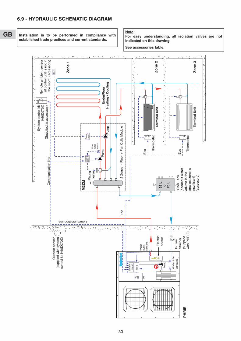
30
GB
6.9 - HYDRAULIC SCHEMATIC DIAGRAM
Rem
ote
ambi
ent
sens
or(if
con
trol
uni
t is
not
inth
e ro
om)
(acc
esso
ry)
Zo
ne
1
Zo
ne
3
Zo
ne
2
2 Z
ones
-
Flo
or +
Fan
Coi
ls M
odul
e
The
rmos
tat
Term
inal
Un
it
Term
inal
Un
it
Boa
rdzo
ne 1
PH
RIE
Out
door
sen
sor
(sup
plie
d w
ith s
yste
mco
ntro
l kit
K60
D07
0Z)
Buf
fer
Tank
(n
eede
d if
wat
ervo
lum
e in
the
smal
lest
zon
e is
insu
ffisa
nt)
(acc
esso
ry)
Sys
tem
con
trol
kit
K60
D07
0Z(S
uppl
ied
in a
cces
sory
)
Ele
ctric
heat
er
In L
ine
Str
aine
r(s
uppl
ied
with
PH
RIE
)
35 L
or
70 L
Eco
Boa
rdzo
ne 2
The
rmos
tat
Sys
tem
boar
d
Wat
erou
tlet
sens
ors
Wat
er in
let
sens
ors
Installation is to be performed in compliance withestablished trade practices and current standards.
Note:For easy understanding, all isolation valves are notindicated on this drawing.
See accessories table.
Pum
p
Com
mun
icat
ion
line
Mix
ing
valv
e
Pum
p
Wat
erou
tlet
sens
or
Un
der
Flo
or
Hea
tin
g /
Co
olin
gP
ump
Communication line
M2Z
M
Eco
Eco

31
GB• ZONE 1 = FLOOR - with circulating pump and control valve (in the M2Z M).
• ZONE 2 = LOW TEMPERATURE RADIATORS - with circulating pump (in the M2Z M).
Warning: In this application, only the heating mode is authorized (cooling mode inactive).
• The operating modes are selected using the rotary knob on the front of the control unit (see § 3.1 and user's manual).
7.1 - HEATING MODE7.1.1 - HEATING OPERATING DIAGRAM
7 - MIXED 2 ZONES FLOOR APPLICATION OPERATION + LOW TEMPERATURE RADIATORS
X
Y2
Y1Z2
Z1
2K2K2K
A water rule is determined foreach zone.
An outside temperature Xdetermines a water temperatureresulting setpoint Y1 for zone 1and Y2 for zone 2.
The parameters determining thiswater rule can be set by theinstaller (see the table in § 7.7).
The resulting setpoint for zone 1 isdisplayed at parameter 04.
The resulting setpoint for zone 2 isdisplayed at parameter 05.
The resulting setpoint (zone 1) canbe corrected as required accordingto the ambient temperature of thezone.
The heat pump is controlledaccording to the highest resultingsetpoint.
The control valve of zone 1 iscontrolled according to theresulting setpoint of the zone.
7.1.2 - “COMFORT” HEATING MODE • Water temperature setpoint
- The circulating pump of each zone is actuated and the zone 1 control valve activated if the outside temperature isless than the non-heating temperature.
- The heat pump can operate only if the outside temperature is less than the non-heating temperature.- A water rule is determined for each zone according to the settings that are specific to the zone. A water temperature
resulting setpoint is calculated according to the outside temperature.- The heat pump and the supplementary heating are thus controlled in relation to the installation's return
temperature according to the highest resulting setpoint (which will be that of zone 2 in the majority of cases -Radiators).Note: The set point value sent to the heat pump can be clipped to the maximum value given in parameter 43.For each zone, the water rule is determined by:
- the non-heating temperature (parameter 23),- the regional minimum temperature (parameter 21),- the minimum temperature of the water circuit (parameters 32 for zone 1, 33 for zone 2),- the maximum temperature of the water circuit (parameters 30 for zone 1, 31 for zone 2).
For zone 1, Floor:
The control valve is controlled by the zone board according to the resulting setpoint of the zone and the watertemperature read by the sensor placed on the zone 1 outgoing line, Floor.
The resulting setpoint can be corrected by the ambient temperature of zone 1:A difference of +/- 1 degree of ambient temperature in relation to the heating setpoint temperature of the zone(adjustable from 15 to 25°C) causes the resulting setpoint (water temperature) to decrease or increase of 2 degrees,respectively. However, this variation cannot exceed +/- 5 degrees.The calculated resulting set point is displayed at parameter 04.
Water temperature setpoint
Outside temperature
Water temperature resultingsetpoint slope in Zone 2
Max. water temp. Z2 (parameter 31)
Min. water temp. (parameter 33)
Heat pump shutdownthreshold
(parameter 20)
Regional min. temperature(parameter 21)
Supplementary heatingauthorization threshold
(parameter 22)
No heating setpoint(parameter 23)
Heat pump authorization
Supplementaryheating authorization
If heat pump alarm or if heat pumpprohibited due to excessively cold water
Water temperature resultingsetpoint slope in Zone 1
Min. water temp. (parameter 32)
Max. water temp. Z1 (parameter 30)
Activation Zone 1 (pump + valve)
Activation Zone 2 (pump)

32
GB
For zone 2, Radiators:This zone is supplied by the heat pump (and supplementary heating, if any). Ambient temperature is controlled bythe thermostatically-controlled valves on the radiators.Setting the zone 2 heating slope (min. and max. water temperature):These settings concern the installation water return temperature ( = heat pump water inlet).As a result, the set water temperatures (parameter 31, 33) must correspond to the outgoing temperature value of theradiator zone less 5 K (typical water Inlet / water Outlet temperature difference for a heat pump).The calculated resulting set point is displayed at parameter 05.
• Control of the heat pump's circulator- The heating mode, activated if the outside temperature is less than the non-heating temperature.- If the circulator is off:
- an “anti-sticking” function starts the circulator for 5 seconds every 24 hours.- The “frost protection” function starts the circulator if the outside temperature is below 0°C.
See details in paragraph 11.
• Supplementary electric heating- The heating elements are actuated if the heat pump is not able to
maintain the water return temperature at the calculated value.The supplementary heating by electrical heating elements isstaged (2 stages). Tiering is managed by a 10-minute time delayfor the 2nd.
- Caution:During normal operation, the supplementary heating is authorizedonly if the outside temperature falls below the authorizationthreshold (parameter 22) corresponding to the installation'sequilibrium temperature and the absence of a load sheddingsignal. However, if can be authorized for greater temperatures ifthe heat pump is experiencing an alarm or if heat pump operation is prohibited by a safety device (and even if a loadshedding signal is present).Supplementary heating is prohibited if it is experiencing an alarm.
• Heat pump operating safety features in heating mode- A safety device on the water temperature (installation return) prohibits heat pump operation if this temperature is
below the thermodynamic heating authorization threshold (parameter 36). In this case, only supplementary heatingis authorized to raise the water temperature and allow the heat pump to operate, regardless of the outsidetemperature (load shedding is thus inoperative). The activation of this safety feature is indicated by the flashing ofthe display.
- Heat pump operation is prohibited if the outside temperature is below the shut-off threshold (parameter 20). Onlysupplementary heating is authorized (load shedding is thus inoperative).
7.1.3 - “ECONOMY” HEATING MODE • It can only be activated in heating mode.• Switching from “Comfort” to “ECO” is accomplished either by hourly programming, weekly programming by zone or by
actuating the rotary knob for the 2 zones.• In the case of hourly programming, the user can activate a temporary override (1 hour + periods of 1 hour during the
current day) per zone.
For zone 1, Floor:- The switch to “ECO” mode lowers the ambient temperature setpoint of the zone by a value than can be adjusted from
1 to 4 K (parameter 24).
For zone 2, Radiators:- No action.
7.1.4 - “ANTI-FREEZE” HEATING MODE (prolonged absence) • Selection for the 2 zones is made using the rotary knob on the control unit.
For zone 1, Floor:- The water temperature resulting setpoint passes to an adjustable
value (parameter 29 is factory-set at 25°C).Zone 1 cannot be activated (circulation pump and regulationvalve) unless ambient temperature in the zone is less than anadjustable set point (parameter 25 set to 12°C in the factory).If ambient temperature in the zone 1 rises above this set point,the circulating pump stops (after a 1 minute delay) and the valveis closed.
For zone 2, Radiators:- The water temperature resulting setpoint of zone 2 is lowered 5 degrees.
7.2 - COOLING MODE• Cooling mode prohibited.
Selecting the “COOL” position on the control unit will cause the system to shutdown. The “OFF” message is displayed.
Water temperature
Supplementary heatingcommand
Resulting setpoint
Ambient temperature
Zone 1activation
Anti-freeze mode ambient temperature setpoint
Parameter 27
Parameter 26

33
GB
7.3 - ELECTRIC HEATER FORCING FOR MAINTENANCE- See details in Service Manual.- When installation system control is “OFF”, it is possible to activate, for a limited time, the electric support heater.- This sequence can only be performed by a qualified technician during maintenance operation.
The sequence is controlled by mean of parameters 40 and 41 after being sure that water circulator is forced andzones activated.
7.4 - HEAT PUMP CONTROL• Forcing: for maintenance operations only, when the system is “OFF”, it is possible to force heat pump control by setting to
parameter 67 to “1”. The heat pump thus operates at the set point given at parameter 43.
7.5 - CONTROL OF ZONE OUTGOING LINES• Managed by the zone board.
7.5.1 - VALVE• Valve, zone 1, Floor in mixed operation.• “3-point” motor (230 VAC) with proportional chrono control:
- Time base = Valve action time (parameter 63)10
- Percentage of the control time = Difference (setpoint / water outlet temperature)Proportional strip (parameter 38)
This percentage is displayed at parameter 17 for zone 1 and 18 for zone 2,(“+” sign = open, “–” sign = closed)In the neutral zone (parameter 39), the valve is not controlled.
• The valve is equipped with a limit switch which detect valve closure (contact closed = valve closed).
7.5.2 - CIRCULATING PUMPS• Pump shutdown is delayed 1 minute.
7.5.3 - FORCING• When the system is “OFF”, and for maintenance operations only, it is possible to force the operation of each zone
(circulating pump on and opening of the zone 1 control valve) by setting parameter 65 to “1” for zone 1 and settingparameter 66 to “1” for zone 2.
7.6 - MISCELLANEOUS• Mode changes using the rotary knob (Heating / Cooling / Anti-freeze / Stop) are delayed 10 seconds in order to filter
inappropriate actions. However, the “Time Setting” and “Hourly Programming” positions do not have the time delayfeature.
• The authorization thresholds on the water temperature are cut-off values with a differential of 1 K for the reset.
Caution: At the end of the operation, forcing must be deactivated (by returning parameter 67 to “0”) beforerestarting the installation.
Caution: At the end of the operation, forcing must be deactivated (by returning parameters 65 and 66 to “0”)before restarting the installation.

34
GBGB
7.7 - PARAMETERS• Access:
- 2 access levels:- Level 1, read only, with direct access for parameters 1 to 19,- Level 2, “technical level” accessible by password “see last page”.
This level is entered via parameter 20, although all parameters are accessible.
Procedure:
1°) Simultaneously press and hold the buttons and for 5 seconds, until thescreen displays PArA.
2°) Select the User menu = Level 1 or Installer = Level 2 using the and buttons.
3°)* To access level 1, press “Z/OK.The display indicates the firstparameter “P01”.
Press the or keys to shift fromone parameter to another.To know the value of the parameter,press “Z/OK”.To redisplay the value of theparameter, press “Z/OK” again.
3Bis°)* To access level 2, press “Z/OK”.
The display shows “ ”.
Enter the password digit by digit, by selecting the desired digit using the or buttons and by confirming with“Z/OK”. Once the password is entered, the display then indicates “P20” which is the first parameter of this level.
To display the value of a parameter, select it using the or keys and press “Z/OK”.
To modify this parameter, if needed, press keys or .To redisplay the value of the parameter, press “Z/OK” again.
4°) To exit the parameterisation procedure, press and hold “Z/OK”.In all cases (except the flow-rate calculation), the display returns to normal automatically after a few minutes ofinactivity.The parameters can be accessed and modified both in operation and when shut down, except for those forinstallation configuration and default parameterisation which can only be accessed and modified when theinstallation is shut down.Note: The flashing parameter values are those that can be modified. Otherwise, the display remains steady.
1: User2: Installer
Access to the 1st parameter(P01)
Display of the parametervalue
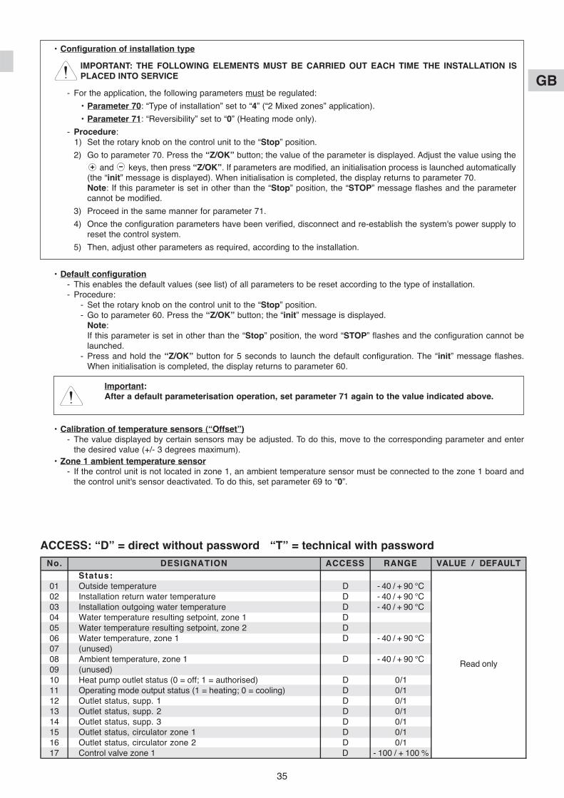
35
GB
ACCESS: “D” = direct without password “T” = technical with password
• Configuration of installation type
IMPORTANT: THE FOLLOWING ELEMENTS MUST BE CARRIED OUT EACH TIME THE INSTALLATION ISPLACED INTO SERVICE
- For the application, the following parameters must be regulated:
• Parameter 70: “Type of installation” set to “4” (“2 Mixed zones” application).
• Parameter 71: “Reversibility” set to “0” (Heating mode only).
- Procedure:1) Set the rotary knob on the control unit to the “Stop” position.
2) Go to parameter 70. Press the “Z/OK” button; the value of the parameter is displayed. Adjust the value using the
and keys, then press “Z/OK”. If parameters are modified, an initialisation process is launched automatically(the “init” message is displayed). When initialisation is completed, the display returns to parameter 70.Note: If this parameter is set in other than the “Stop” position, the “STOP” message flashes and the parametercannot be modified.
3) Proceed in the same manner for parameter 71.
4) Once the configuration parameters have been verified, disconnect and re-establish the system's power supply toreset the control system.
5) Then, adjust other parameters as required, according to the installation.
• Default configuration- This enables the default values (see list) of all parameters to be reset according to the type of installation.- Procedure:
- Set the rotary knob on the control unit to the “Stop” position.- Go to parameter 60. Press the “Z/OK” button; the “init” message is displayed.
Note: If this parameter is set in other than the “Stop” position, the word “STOP” flashes and the configuration cannot belaunched.
- Press and hold the “Z/OK” button for 5 seconds to launch the default configuration. The “init” message flashes.When initialisation is completed, the display returns to parameter 60.
• Calibration of temperature sensors (“Offset”)- The value displayed by certain sensors may be adjusted. To do this, move to the corresponding parameter and enter
the desired value (+/- 3 degrees maximum).• Zone 1 ambient temperature sensor
- If the control unit is not located in zone 1, an ambient temperature sensor must be connected to the zone 1 board andthe control unit's sensor deactivated. To do this, set parameter 69 to “0”.
No. DESIGNATION ACCESS RANGE VALUE / DEFAULTStatus:
01 Outside temperature D - 40 / + 90 °C02 Installation return water temperature D - 40 / + 90 °C03 Installation outgoing water temperature D - 40 / + 90 °C04 Water temperature resulting setpoint, zone 1 D05 Water temperature resulting setpoint, zone 2 D06 Water temperature, zone 1 D - 40 / + 90 °C07 (unused)08 Ambient temperature, zone 1 D - 40 / + 90 °C09 (unused)10 Heat pump outlet status (0 = off; 1 = authorised) D 0/111 Operating mode output status (1 = heating; 0 = cooling) D 0/112 Outlet status, supp. 1 D 0/113 Outlet status, supp. 2 D 0/114 Outlet status, supp. 3 D 0/115 Outlet status, circulator zone 1 D 0/116 Outlet status, circulator zone 2 D 0/117 Control valve zone 1 D - 100 / + 100 %
Read only
Important: After a default parameterisation operation, set parameter 71 again to the value indicated above.

36
GB
No. DESIGNATION ACCESS RANGE VALUE / DEFAULTAir temperature settings:
20 Heat pump shut-down threshold T - 20 / 0 °C - 16 °C21 Regional min. temperature T - 20 / 5 °C - 7 °C22 Supplementary authorization threshold T - 5 / 20 °C 7 °C23 No heating threshold T 10 / 25 °C 17 °C24 Lowering of ECO temperature (ambience) T 1 / 4 K 2 K25 Ambient temperature set point at anti-freeze T 8 / 18 °C 12 °C
Water temperature settings:26 Supplementary heating control hysteresis T 2 / P27 K 2 K27 Supplementary heating control lag T P26 / 6 K 3.5 K28 Heat pump control hysteresis - unused T 1 / 4 K 2.5 K29 Water temperature setpoint in "anti-freeze" mode T 20 / 35 °C 25 °C30 Outgoing heating water max. temperature, zone 1 T 25 / 40 °C 35 °C31 Heating water max. temperature, zone 2 (installation return) T 35 / 45 °C 40 °C32 Outgoing heating water min. temperature, zone 1 T 20 / 30 °C 20 °C33 Heating water min. temperature, zone 2 (installation return) T 20 / 35 °C 30 °C34 Outgoing cooling water temperature, zone 1 - unused T 15 / 25 °C 20 °C35 Cooling authorization threshold (installation return) - unused T 25 / 50 °C 30 °C36 Thermodynamic heating authorization threshold (installation return) T 10 / 20 °C 15 °C37 Water outlet temperature max. alarm threshold T 60 / 90 °C 70 °C38 Zone 1 valve control proportional strip T 1 / 10 K 5 K39 Zone 1 valve control neutral zone T 1 / 4 K 1 K
Electric heater forcing (for maintenance only):40 Total electric heating capacity T 1 / 30 kW 6 kW41 Launch of the sequence T
Heat pump Inverter parameters:42 Water temperature set point (return), cooling - unused T 10 / 30 °C 12 °C43 Maximum water temperature set point (return), heating T 40 / 50 °C 50 °C
Sensor offset:50 Outside sensor T + or - 3 K 051 Zone 1 air temperature sensor T + or - 3 K 052 (unused)53 Installation return water temperature sensor T + or - 3 K 054 Installation outlet water temperature sensor T + or - 3 K 0
Miscellaneous:60 Default configuration T61 TYPHONE language selection (1 = FR ; 2 = GB) T 1/2 162 TYPHONE access code T 0/9999 123463 Zone 1 valve action time T 60 / 300 sec. 150 sec.64 Heat pump min. operating time T 0 / 200 sec. 100 sec.65 Forcing, zone 1 (off) T 0/1 066 Forcing, zone 2 (off) T 0/1 067 Heat pump forcing (active when off) T 0/1 068 (unused)69 Ambient temperature sensor, zone 1 (1 = control unit) T 0/1 1
Configuration:70 Installation type T 1/5
1 = 1 Zone, floor2 = 2 Zones, floor3 = Unused Set to:4 = Mixed 45 = Terminal units6 = 1 Zone radiators
71 Reversibility (1 = reversible - 0 = heating only) T 0/1 1 by default - set to 075 Load shedding action (1 = closed contact = load shedding) T 0/1 176 CWC2 board activation (1 = Activated) T 0/1 1
Software versions:80 Control unit T81 Heating board T82 Board zone 1 T83 Board zone 2 T85 CWC2 board T
Ambience setpoints: D
Heating setpoint zone 1 15 / 25 °C 20 °C
Direct accessKeypadCooling setpoint zone 1 - unused
Read only
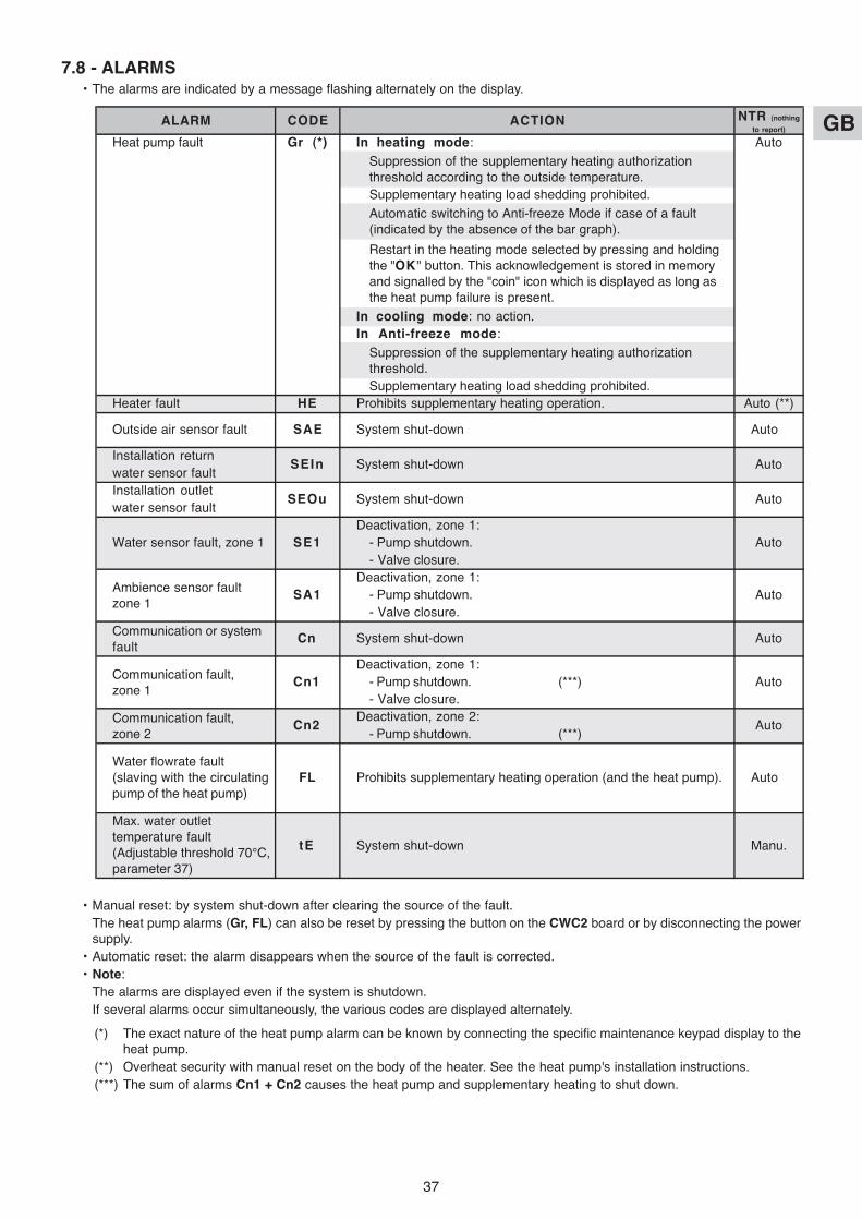
37
GB
7.8 - ALARMS• The alarms are indicated by a message flashing alternately on the display.
• Manual reset: by system shut-down after clearing the source of the fault.The heat pump alarms (Gr, FL) can also be reset by pressing the button on the CWC2 board or by disconnecting the powersupply.
• Automatic reset: the alarm disappears when the source of the fault is corrected.• Note:
The alarms are displayed even if the system is shutdown.If several alarms occur simultaneously, the various codes are displayed alternately.
(*) The exact nature of the heat pump alarm can be known by connecting the specific maintenance keypad display to theheat pump.
(**) Overheat security with manual reset on the body of the heater. See the heat pump's installation instructions.(***) The sum of alarms Cn1 + Cn2 causes the heat pump and supplementary heating to shut down.
ALARM CODE ACTION NTR (nothing
to report)
Heat pump fault Gr (*) In heating mode: Auto
Supplementary heating load shedding prohibited.
In cooling mode: no action.In Anti-freeze mode:
Supplementary heating load shedding prohibited.Heater fault HE Prohibits supplementary heating operation. Auto (**)
Installation returnwater sensor faultInstallation outletwater sensor fault
Deactivation, zone 1:- Pump shutdown.- Valve closure.
Deactivation, zone 1:- Pump shutdown.- Valve closure.
Deactivation, zone 1:- Pump shutdown. (***)- Valve closure.
Deactivation, zone 2:- Pump shutdown. (***)
Suppression of the supplementary heating authorizationthreshold according to the outside temperature.
Automatic switching to Anti-freeze Mode if case of a fault(indicated by the absence of the bar graph).
Restart in the heating mode selected by pressing and holdingthe "OK" button. This acknowledgement is stored in memoryand signalled by the "coin" icon which is displayed as long asthe heat pump failure is present.
Suppression of the supplementary heating authorizationthreshold.
Outside air sensor fault SAE System shut-down Auto
SEIn System shut-down Auto
SEOu System shut-down Auto
Ambience sensor faultzone 1
SA1 Auto
Water sensor fault, zone 1 SE1 Auto
Communication or systemfault
Cn System shut-down Auto
Auto
Communication fault,zone 1
Cn1 Auto
Communication fault,zone 2
Cn2 Auto
Water flowrate fault(slaving with the circulatingpump of the heat pump)
FL Prohibits supplementary heating operation (and the heat pump).
Max. water outlettemperature fault(Adjustable threshold 70°C,parameter 37)
tE System shut-down Manu.

38
GB
Mix
ing
tank
(acc
esso
ry)
Zo
ne
1
Zo
ne
2
2 Z
ones
- F
loor
+
Rad
iato
rs L
ow T
empe
ratu
re
Dis
char
ge v
alve
(not
sup
plie
d)R
adia
tors
Lo
wTe
mp
erat
ure
Rad
iato
rs L
ow
Tem
per
atu
re
Inst
all
ther
mos
tatic
valv
e on
all
radi
ator
s lo
wte
mpe
ratu
re
7.9 - HYDRAULIC SCHEMATIC DIAGRAM
Rem
ote
ambi
ent
sens
or(if
con
trol
uni
t is
not
in t
he r
oom
)(a
cces
sory
)
Boa
rdzo
ne 1
PH
RIE
Out
door
sen
sor
(sup
plie
d w
ith s
yste
mco
ntro
l kit
K60
D07
0Z)
Ele
ctric
hea
ter
In L
ine
Str
aine
r(s
uppl
ied
with
PH
RIE
)
70 L
Boa
rdzo
ne 2
Floo
r (H
eati
ng
on
ly)
Dirt
sep
arat
or(a
cces
sory
)
Sys
tem
boar
d
Wat
erou
tlet
sens
ors
Wat
er in
let
sens
ors
Installation is to be performed in compliance withestablished trade practices and current standards.
Note:For easy understanding, all isolation valves are notindicated on this drawing.
See accessories table.
Pum
p
Sys
tem
con
trol
kit
K60
D07
0Z(S
uppl
ied
in a
cces
sory
)
Com
mun
icat
ion
line
Mix
ing
valv
e
Pum
p
M2Z
M
Com
mun
icat
ion
line
Pum
p
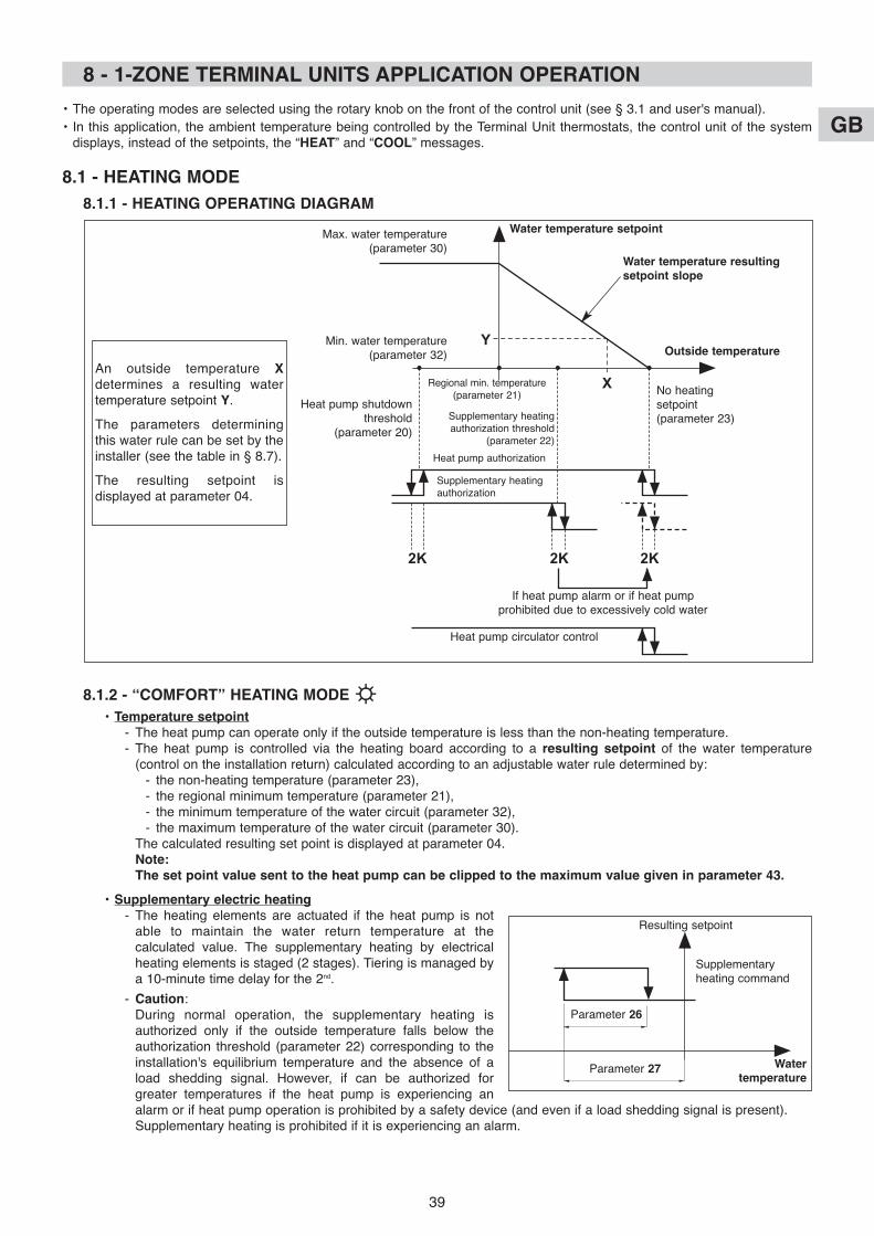
39
GB
X
2K2K2K
Y
An outside temperature Xdetermines a resulting watertemperature setpoint Y.
The parameters determiningthis water rule can be set by theinstaller (see the table in § 8.7).
The resulting setpoint isdisplayed at parameter 04.
• The operating modes are selected using the rotary knob on the front of the control unit (see § 3.1 and user's manual).• In this application, the ambient temperature being controlled by the Terminal Unit thermostats, the control unit of the system
displays, instead of the setpoints, the “HEAT” and “COOL” messages.
8.1 - HEATING MODE8.1.1 - HEATING OPERATING DIAGRAM
8 - 1-ZONE TERMINAL UNITS APPLICATION OPERATION
Heat pump circulator control
8.1.2 - “COMFORT” HEATING MODE • Temperature setpoint
- The heat pump can operate only if the outside temperature is less than the non-heating temperature.- The heat pump is controlled via the heating board according to a resulting setpoint of the water temperature
(control on the installation return) calculated according to an adjustable water rule determined by:- the non-heating temperature (parameter 23),- the regional minimum temperature (parameter 21),- the minimum temperature of the water circuit (parameter 32),- the maximum temperature of the water circuit (parameter 30).
The calculated resulting set point is displayed at parameter 04.Note:The set point value sent to the heat pump can be clipped to the maximum value given in parameter 43.
• Supplementary electric heating- The heating elements are actuated if the heat pump is not
able to maintain the water return temperature at thecalculated value. The supplementary heating by electricalheating elements is staged (2 stages). Tiering is managed bya 10-minute time delay for the 2nd.
- Caution:During normal operation, the supplementary heating isauthorized only if the outside temperature falls below theauthorization threshold (parameter 22) corresponding to theinstallation's equilibrium temperature and the absence of aload shedding signal. However, if can be authorized forgreater temperatures if the heat pump is experiencing analarm or if heat pump operation is prohibited by a safety device (and even if a load shedding signal is present).Supplementary heating is prohibited if it is experiencing an alarm.
Watertemperature
Supplementaryheating command
Resulting setpoint
Parameter 26
Parameter 27
Water temperature setpoint
Outside temperature
Water temperature resultingsetpoint slope
Max. water temperature(parameter 30)
Min. water temperature(parameter 32)
Heat pump shutdownthreshold
(parameter 20)
Regional min. temperature(parameter 21)
Supplementary heatingauthorization threshold
(parameter 22)
No heatingsetpoint(parameter 23)
Heat pump authorization
Supplementary heatingauthorization
If heat pump alarm or if heat pumpprohibited due to excessively cold water
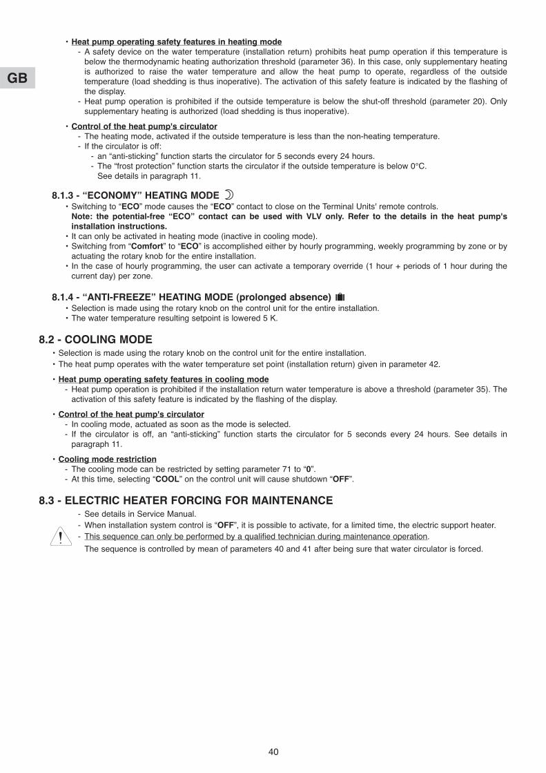
40
GB
• Heat pump operating safety features in heating mode- A safety device on the water temperature (installation return) prohibits heat pump operation if this temperature is
below the thermodynamic heating authorization threshold (parameter 36). In this case, only supplementary heatingis authorized to raise the water temperature and allow the heat pump to operate, regardless of the outsidetemperature (load shedding is thus inoperative). The activation of this safety feature is indicated by the flashing ofthe display.
- Heat pump operation is prohibited if the outside temperature is below the shut-off threshold (parameter 20). Onlysupplementary heating is authorized (load shedding is thus inoperative).
• Control of the heat pump's circulator- The heating mode, activated if the outside temperature is less than the non-heating temperature.- If the circulator is off:
- an “anti-sticking” function starts the circulator for 5 seconds every 24 hours.- The “frost protection” function starts the circulator if the outside temperature is below 0°C.
See details in paragraph 11.
8.1.3 - “ECONOMY” HEATING MODE • Switching to “ECO” mode causes the “ECO” contact to close on the Terminal Units' remote controls.
Note: the potential-free “ECO” contact can be used with VLV only. Refer to the details in the heat pump'sinstallation instructions.
• It can only be activated in heating mode (inactive in cooling mode).• Switching from “Comfort” to “ECO” is accomplished either by hourly programming, weekly programming by zone or by
actuating the rotary knob for the entire installation.• In the case of hourly programming, the user can activate a temporary override (1 hour + periods of 1 hour during the
current day) per zone.
8.1.4 - “ANTI-FREEZE” HEATING MODE (prolonged absence) • Selection is made using the rotary knob on the control unit for the entire installation.• The water temperature resulting setpoint is lowered 5 K.
8.2 - COOLING MODE• Selection is made using the rotary knob on the control unit for the entire installation.• The heat pump operates with the water temperature set point (installation return) given in parameter 42.
• Heat pump operating safety features in cooling mode- Heat pump operation is prohibited if the installation return water temperature is above a threshold (parameter 35). The
activation of this safety feature is indicated by the flashing of the display.
• Control of the heat pump's circulator- In cooling mode, actuated as soon as the mode is selected.- If the circulator is off, an “anti-sticking” function starts the circulator for 5 seconds every 24 hours. See details in
paragraph 11.
• Cooling mode restriction- The cooling mode can be restricted by setting parameter 71 to “0”.- At this time, selecting “COOL” on the control unit will cause shutdown “OFF”.
8.3 - ELECTRIC HEATER FORCING FOR MAINTENANCE- See details in Service Manual.- When installation system control is “OFF”, it is possible to activate, for a limited time, the electric support heater.- This sequence can only be performed by a qualified technician during maintenance operation.
The sequence is controlled by mean of parameters 40 and 41 after being sure that water circulator is forced.

41
GB
8.4 - 2nd ZONE - ELECTRIC CONVECTORS• A 2nd zone equipped with electric convectors can also be managed (Max. number = 20). These appliances must be equipped
with an electronic thermostat (not included) able to receive signals via a 230 VAC pilot wire (standard GIFAM 4).• The 2nd zone is activated by setting the micro-switch in the back of the control unit to the “ON” position.
- In “Comfort”, “ECO” or “Anti-freeze” heating modes, the corresponding signals are transmitted to the 2nd zone.- In cooling mode and in the Stop position, the shut-down signal is transmitted to the 2nd zone.- In heating mode with hourly programming, the “Comfort” or “ECO” signals are transmitted to the 2nd zone according
to the corresponding hourly programming.Note: In case of load shedding, a shut-down signal is transmitted to the 2nd zone.
- In heating mode, the display unit indicates for the zone 2 “HEAT”.
8.5 - MISCELLANEOUS• Mode changes using the rotary knob (Heating / Cooling / Anti-freeze / Stop) are delayed 10 seconds in order to filter
inappropriate actions. However, the “Time Setting” and “Hourly Programming” positions do not have the time delayfeature.
• The authorization thresholds on the water temperature are cut-off values with a differential of 1 K for the reset.
8.6 - PARAMETERS• Access:
- 2 access levels:- Level 1, read only, with direct access for parameters 1 to 19,- Level 2, “technical level” accessible by password “see last page”.
This level is entered via parameter 20, although all parameters are accessible.
Procedure:
1°) Simultaneously press and hold the buttons and for 5 seconds, untilthe screen displays PArA.
2°) Select the User menu = Level 1 or Installer = Level 2 using the and
buttons.
3°)* To access level 1, press “Z/OK.The display indicates the firstparameter “P01”.
Press the or keys to shift fromone parameter to another.To know the value of the parameter,press “Z/OK”.To redisplay the value of theparameter, press “Z/OK” again.
3Bis°)* To access level 2, press “Z/OK”.
The display shows “ ”.
Enter the password digit by digit, by selecting the desired digit using the or buttons and by confirming with“Z/OK”. Once the password is entered, the display then indicates “P20” which is the first parameter of this level.
To display the value of a parameter, select it using the or keys and press “Z/OK”.
To modify this parameter, if needed, press keys or .To redisplay the value of the parameter, press “Z/OK” again.
4°) To exit the parameterisation procedure, press and hold “Z/OK”.In all cases (except the flow-rate calculation), the display returns to normal automatically after a few minutes ofinactivity.The parameters can be accessed and modified both in operation and when shut down, except for those forinstallation configuration and default parameterisation which can only be accessed and modified when theinstallation is shut down.Note: The flashing parameter values are those that can be modified. Otherwise, the display remains steady.
1: User2: Installer
Access to the 1st parameter (P01) Display of the parameter value

42
GB
• Configuration of installation type
IMPORTANT: THE FOLLOWING ELEMENTS MUST BE CARRIED OUT EACH TIME THE INSTALLATION ISPLACED INTO SERVICE
- For the Terminal Units application, parameter 70 must be set to “5”.- Procedure:
1) Set the rotary knob on the control unit to the “Stop” position.2) Go to parameter 70. Press the “Z/OK” button; the value of the parameter is displayed. This value may be read or
modified using the and buttons if the system is in the “Stop” position. If parameters are modified, aninitialisation process is launched automatically (the “init” message is displayed). When initialisation is completed,the display returns to parameter 70.Note: If this parameter is set in other than the “Stop” position, the “STOP” message flashes and the parametercannot be modified.
3) Once the configuration parameters have been verified, disconnect and re-establish the system's power supply toreset the control system.
• Default configuration- This enables the default values (see list) of all parameters to be reset according to the type of installation.- Procedure:
- Set the rotary knob on the control unit to the “Stop” position.- Go to parameter 60. Press the “Z/OK” button; the “init” message is displayed.
Note: If this parameter is set in other than the “Stop” position, the word “STOP” flashes and the configuration cannot belaunched.
- Press and hold the “Z/OK” button for 5 seconds to launch the default configuration. The “init” message flashes.When initialisation is completed, the display returns to parameter 60.
• Calibration of temperature sensors (“Offset”)- The value displayed by certain sensors may be adjusted. To do this, move to the corresponding parameter and enter
the desired value (+/- 3 degrees maximum).• Heat pump control forcing
- For maintenance operations only, when the system is “OFF”, it is possible to force heat pump control by setting toparameter 67 to “1”. The heat pump operates in heating mode at the set point given at parameter 43.
Caution: At the end of the operation, forcing must be deactivated (by returning parameter 67 to “0”) beforerestarting the installation.
ACCESS: “D” = direct without password “T” = technical with password
No. DESIGNATION ACCESS RANGE VALUE / DEFAULT
Status:01 Outside temperature D - 40 / + 90 °C02 Installation return water temperature D - 40 / + 90 °C03 Installation outgoing water temperature D - 40 / + 90 °C04 Water temperature resulting setpoint D05 (unused)06 (unused)07 (unused)08 Ambient temperature, zone 1 D - 40 / + 90 °C09 (unused)10 Heat pump outlet status (0 = off; 1 = authorised) D 0/111 Operating mode output status (1 = heating; 0 = cooling) D 0/112 Outlet status, supp. 1 D 0/113 Outlet status, supp. 2 D 0/114 Outlet status, supp. 3 D 0/1
Air temperature settings:20 Heat pump shut-down threshold T - 20 / 0 °C - 16 °C21 Regional min. temperature T - 20 / 5 °C - 7 °C22 Supplementary authorization threshold T - 5 / 20 °C 7 °C23 No heating threshold T 15 / 30 °C 17 °C
Read only
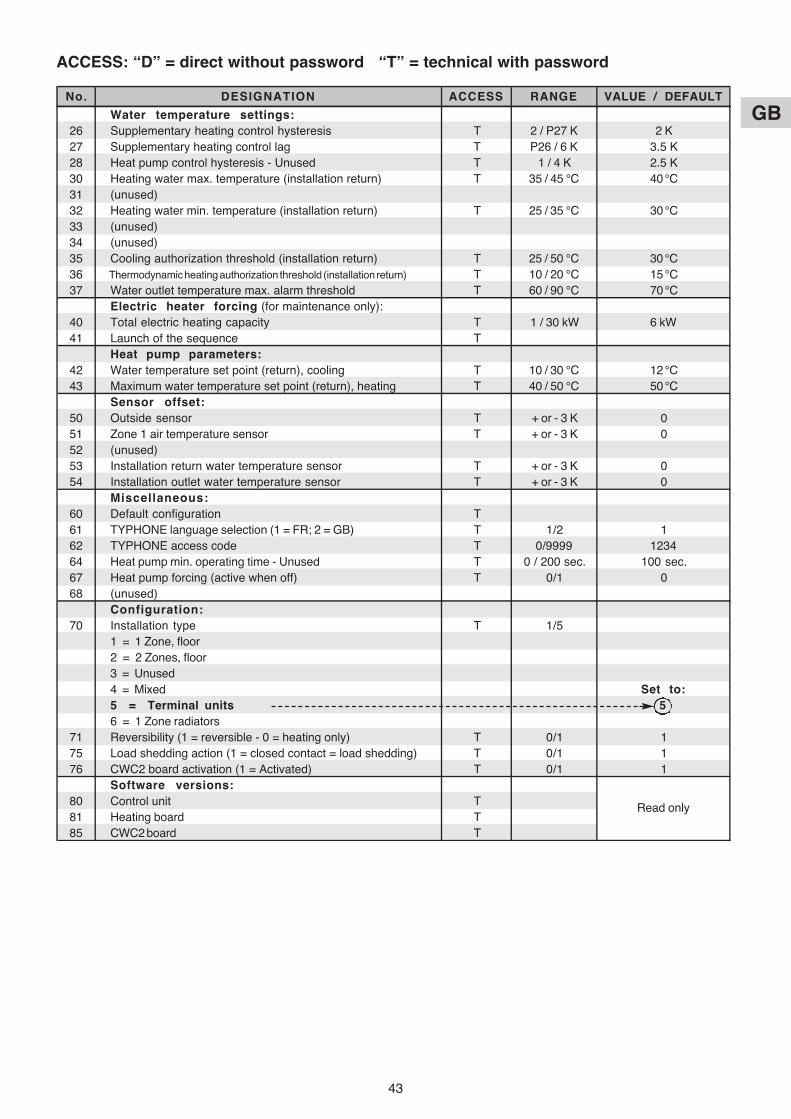
43
GB
ACCESS: “D” = direct without password “T” = technical with password
No. DESIGNATION ACCESS RANGE VALUE / DEFAULT
Water temperature settings:26 Supplementary heating control hysteresis T 2 / P27 K 2 K27 Supplementary heating control lag T P26 / 6 K 3.5 K28 Heat pump control hysteresis - Unused T 1 / 4 K 2.5 K30 Heating water max. temperature (installation return) T 35 / 45 °C 40 °C31 (unused)32 Heating water min. temperature (installation return) T 25 / 35 °C 30 °C33 (unused)34 (unused)35 Cooling authorization threshold (installation return) T 25 / 50 °C 30 °C36 Thermodynamic heating authorization threshold (installation return) T 10 / 20 °C 15 °C37 Water outlet temperature max. alarm threshold T 60 / 90 °C 70 °C
Electric heater forcing (for maintenance only):40 Total electric heating capacity T 1 / 30 kW 6 kW41 Launch of the sequence T
Heat pump parameters:42 Water temperature set point (return), cooling T 10 / 30 °C 12 °C43 Maximum water temperature set point (return), heating T 40 / 50 °C 50 °C
Sensor offset:50 Outside sensor T + or - 3 K 051 Zone 1 air temperature sensor T + or - 3 K 052 (unused)53 Installation return water temperature sensor T + or - 3 K 054 Installation outlet water temperature sensor T + or - 3 K 0
Miscellaneous:60 Default configuration T61 TYPHONE language selection (1 = FR; 2 = GB) T 1/2 162 TYPHONE access code T 0/9999 123464 Heat pump min. operating time - Unused T 0 / 200 sec. 100 sec.67 Heat pump forcing (active when off) T 0/1 068 (unused)
Configuration:70 Installation type T 1/5
1 = 1 Zone, floor2 = 2 Zones, floor3 = Unused4 = Mixed Set to:5 = Terminal units 56 = 1 Zone radiators
71 Reversibility (1 = reversible - 0 = heating only) T 0/1 175 Load shedding action (1 = closed contact = load shedding) T 0/1 176 CWC2 board activation (1 = Activated) T 0/1 1
Software versions:80 Control unit T81 Heating board T85 CWC2 board T
Read only

44
GB
8.7 - ALARMS• The alarms are indicated by a message flashing alternately on the display.
• Manual reset: by system shut-down after clearing the source of the fault.The heat pump alarms (Gr, FL) can also be reset by pressing the button on the CWC2 board or by disconnecting the powersupply.
• Automatic reset: the alarm disappears when the source of the fault is corrected.• Note:
The alarms are displayed even if the system is shutdown.If several alarms occur simultaneously, the various codes are displayed alternately.
(*) The exact nature of the heat pump alarm can be known by connecting the specific maintenance keypad display to theheat pump.
(**)Overheat security with manual reset on the body of the heater. See the heat pump's installation instructions.
ALARM CODE ACTION NTR (nothing
to report)
Heat pump fault Gr (*) In heating mode: Manu.
Supplementary heating load shedding prohibited.
In cooling mode: heat pump shutdown.In Anti-freeze mode:
Supplementary heating load shedding prohibited.Heater fault HE Prohibits supplementary heating operation. Auto (**)
Heating: operation with resulting setpoint 40 °C.Suppression of outside temperature thresholds.Cooling: no action.
Installation outletwater sensor fault
Water flowrate fault FL Prohibits supplementary heating operation (and the heat pump). Manu.
Max. water outlettemperature fault(Adjustable threshold 70°C,parameter 37)
tE System shut-down Manu.
Installation return watersensor fault
Communication or systemfault
Cn System shut-down Auto
SEIn System shut-down Auto
SEOu System shut-down Auto
Outside air sensor fault SAE Auto
Suppression of the supplementary heating authorizationthreshold according to the outside temperature.
Automatic switching to Anti-freeze Mode if case of a fault(indicated by the absence of the bar graph).Restart in the heating mode selected by pressing and holdingthe "OK" button. This acknowledgement is stored in memoryand signalled by the "coin" icon which is displayed as long asthe heat pump failure is present.
Suppression of the supplementary heating authorizationthreshold.

45
GB
8.8 - HYDRAULIC SCHEMATIC DIAGRAM
Buf
fer
tank
(I
f w
ater
vol
ume
need
ed)
(acc
esso
ry)
Eco
Term
inal
Un
it
Term
inal
Un
it
The
rmos
tat
Term
inal
Un
it
The
rmos
tat
The
rmos
tat
Ro
om
1
Ele
ctric
heat
er
In L
ine
Str
aine
r(s
uppl
ied
with
PH
RIE
)
35 L
or
70 L
Ro
om
2
Ro
om
3
PH
RIE
Sys
tem
boar
d
Wat
er in
let
sens
ors
Out
door
sen
sor
(sup
plie
d w
ith s
yste
mco
ntro
l kit
K60
D07
0Z)
Pum
p
Sys
tem
con
trol
kit
K60
D07
0Z(S
uppl
ied
in a
cces
sory
)
Com
mun
icat
ion
line
Eco
Eco
Eco
Installation is to be performed in compliance withestablished trade practices and current standards.
Note:For easy understanding, all isolation valves are notindicated on this drawing.
See accessories table.
Wat
erou
tlet
sens
ors

46
GB• The operating modes are selected using the rotary knob on the front of the control unit (see § 3.1 and user's manual).
9.1 - HEATING MODE9.1.1 - HEATING OPERATING DIAGRAM
9 - 1-ZONE LOW TEMPERATURE RADIATORS APPLICATION OPERATION
X
2K2K2K
Y
An outside temperature Xdetermines a resulting watertemperature setpoint Y.
The parameters determiningthis water rule can be set by theinstaller (see the table in § 9.6).
The resulting setpoint isdisplayed at parameter 04.It can be corrected as requireddepending on the ambienttemperature of the zone.
9.1.2 - “COMFORT” HEATING MODE • Temperature setpoint
- The heat pump can operate only if the outside temperature is less than the non-heating temperature.- The heat pump is controlled according to a resulting set point of the water temperature.- Control on installation return calculated according to an adjustable water law, determined by:
- the non-heating temperature (parameter 23),- the regional minimum temperature (parameter 21),- the minimum temperature of the water circuit (parameter 32),- the maximum temperature of the water circuit (parameter 30).
The resulting setpoint calculated in this manner can be corrected by the temperature of the zone:A difference of +/- 1 degree of ambient temperature in relation to the heating setpoint temperature of the zone(adjustable from 15 to 25°C) causes the resulting setpoint (water temperature) to decrease or increase of 3 degrees,respectively. However, this variation cannot exceed +/- 5 degrees.The calculated resulting set point is displayed at parameter 04.Note:The set point value sent to the heat pump can be clipped to the maximum value given in parameter 43.
• Supplementary electric heating- The heating elements are actuated if the heat pump is not able to maintain the water return temperature at the
calculated value. The supplementary heating by electrical heating elements is staged (2 stages). Tiering is managedby a 10-minute time delay for the 2nd.
- Caution:During normal operation, the supplementary heating is authorizedonly if the outside temperature falls below the authorization threshold(parameter 22) corresponding to the installation's equilibriumtemperature and the absence of a load shedding signal. However, ifcan be authorized for greater temperatures if the heat pump isexperiencing an alarm or if heat pump operation is prohibited by asafety device (and even if a load shedding signal is present).Supplementary heating is prohibited if it is experiencing an alarm.
Watertemperature
Supplementaryheating command
Resulting setpoint
Parameter 26
Parameter 27
Heat pump circulator control
Water temperature setpoint
Outside temperature
Water temperature resultingsetpoint slope
Max. water temperature(parameter 30)
Min. water temperature(parameter 32)
Heat pump shutdownthreshold
(parameter 20)
Regional min. temperature(parameter 21)
Supplementary heatingauthorization threshold
(parameter 22)
No heatingsetpoint(parameter 23)
Heat pump authorization
Supplementary heatingauthorization
If heat pump alarm or if heat pumpprohibited due to excessively cold water

47
GB
• Heat pump operating safety features in heating mode- A safety device on the water temperature (installation return) prohibits heat pump operation if this temperature is
below the thermodynamic heating authorization threshold (parameter 36). In this case, only supplementary heatingis authorized to raise the water temperature and allow the heat pump to operate, regardless of the outsidetemperature (load shedding is thus inoperative). The activation of this safety feature is indicated by the flashing ofthe display.
- Heat pump operation is prohibited if the outside temperature is below the shut-off threshold (parameter 20). Onlysupplementary heating is authorized (load shedding is thus inoperative).
• Limitation on ambient temperature- In heating mode, operation of the heat pump and the electric heater (if any) is prohibited if the ambient temperature
of the zone exceeds the ambient set point temperature by 3.5°C. The operation is authorized once again if theambient temperature falls to the ambient set point value.
• Control of the heat pump's circulator- The heating mode, activated if the outside temperature is less than the non-heating temperature.- If the circulator is off:
- an “anti-sticking” function starts the circulator for 5 seconds every 24 hours.- The “frost protection” function starts the circulator if the outside temperature is below 0°C.
See details in paragraph 11.
9.1.3 - “ECONOMY” HEATING MODE • The switch to “ECO” mode lowers the ambient temperature setpoint by a value than can be adjusted from 1 to 4 K
(parameter 24).• It can only be activated in heating mode (inactive in cooling mode).• Switching from “Comfort” to “ECO” is accomplished either by hourly programming, weekly programming by zone or by
actuating the rotary knob for the entire installation.• In the case of hourly programming, the user can activate a temporary override (1 hour + periods of 1 hour during the
current day) per zone.
9.1.4 - “ANTI-FREEZE” HEATING MODE (prolonged absence) • Selection is made using the rotary knob on the control unit
for the entire installation.• The water temperature resulting setpoint passes to an
adjustable value (parameter 29 is factory-set at 35°C). Heating (heat pump + supplementary heating, if any) isactuated depending on the ambient temperature setpointadjustable (parameter 25 set to 12°C in the factory).
9.2 - COOLING MODEThis mode cannot be activated in the application.• Selection of the “COOL” position (Summer) on the control unit has the same effect as switching off the system. “OFF” is
displayed.
9.3 - ELECTRIC HEATER FORCING FOR MAINTENANCE- See details in Service Manual.- When installation system control is “OFF”, it is possible to activate, for a limited time, the electric support heater.- This sequence can only be performed by a qualified technician during maintenance operation.
The sequence is controlled by mean of parameters 40 and 41 after being sure that the heat pump water circulator isforced and installation circulator is operating.
Ambient temperature
Heating command
Anti-freeze mode ambient temperature setpoint
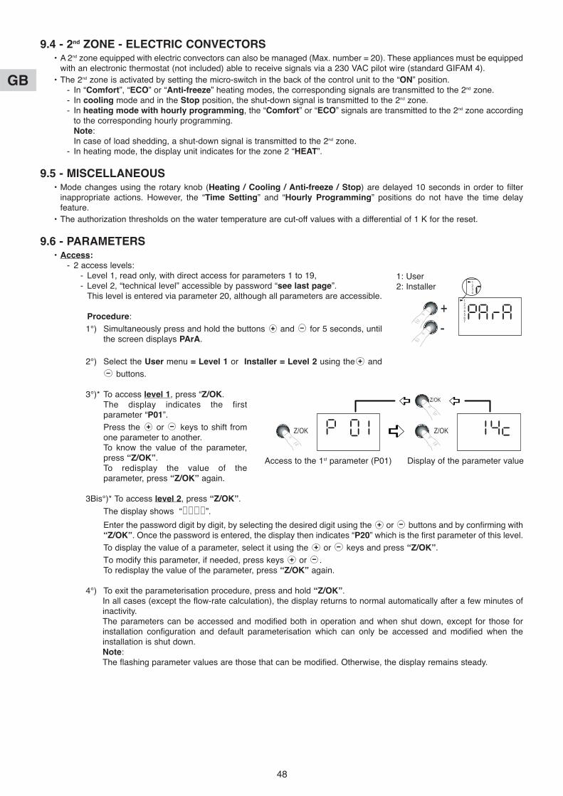
48
GB
9.4 - 2nd ZONE - ELECTRIC CONVECTORS• A 2nd zone equipped with electric convectors can also be managed (Max. number = 20). These appliances must be equipped
with an electronic thermostat (not included) able to receive signals via a 230 VAC pilot wire (standard GIFAM 4).• The 2nd zone is activated by setting the micro-switch in the back of the control unit to the “ON” position.
- In “Comfort”, “ECO” or “Anti-freeze” heating modes, the corresponding signals are transmitted to the 2nd zone.- In cooling mode and in the Stop position, the shut-down signal is transmitted to the 2nd zone.- In heating mode with hourly programming, the “Comfort” or “ECO” signals are transmitted to the 2nd zone according
to the corresponding hourly programming.Note: In case of load shedding, a shut-down signal is transmitted to the 2nd zone.
- In heating mode, the display unit indicates for the zone 2 “HEAT”.
9.5 - MISCELLANEOUS• Mode changes using the rotary knob (Heating / Cooling / Anti-freeze / Stop) are delayed 10 seconds in order to filter
inappropriate actions. However, the “Time Setting” and “Hourly Programming” positions do not have the time delayfeature.
• The authorization thresholds on the water temperature are cut-off values with a differential of 1 K for the reset.
9.6 - PARAMETERS• Access:
- 2 access levels:- Level 1, read only, with direct access for parameters 1 to 19,- Level 2, “technical level” accessible by password “see last page”.
This level is entered via parameter 20, although all parameters are accessible.
Procedure:
1°) Simultaneously press and hold the buttons and for 5 seconds, untilthe screen displays PArA.
2°) Select the User menu = Level 1 or Installer = Level 2 using the and
buttons.
3°)* To access level 1, press “Z/OK.The display indicates the firstparameter “P01”.
Press the or keys to shift fromone parameter to another.To know the value of the parameter,press “Z/OK”.To redisplay the value of theparameter, press “Z/OK” again.
3Bis°)* To access level 2, press “Z/OK”.
The display shows “ ”.
Enter the password digit by digit, by selecting the desired digit using the or buttons and by confirming with“Z/OK”. Once the password is entered, the display then indicates “P20” which is the first parameter of this level.
To display the value of a parameter, select it using the or keys and press “Z/OK”.
To modify this parameter, if needed, press keys or .To redisplay the value of the parameter, press “Z/OK” again.
4°) To exit the parameterisation procedure, press and hold “Z/OK”.In all cases (except the flow-rate calculation), the display returns to normal automatically after a few minutes ofinactivity.The parameters can be accessed and modified both in operation and when shut down, except for those forinstallation configuration and default parameterisation which can only be accessed and modified when theinstallation is shut down.Note: The flashing parameter values are those that can be modified. Otherwise, the display remains steady.
1: User2: Installer
Access to the 1st parameter (P01) Display of the parameter value
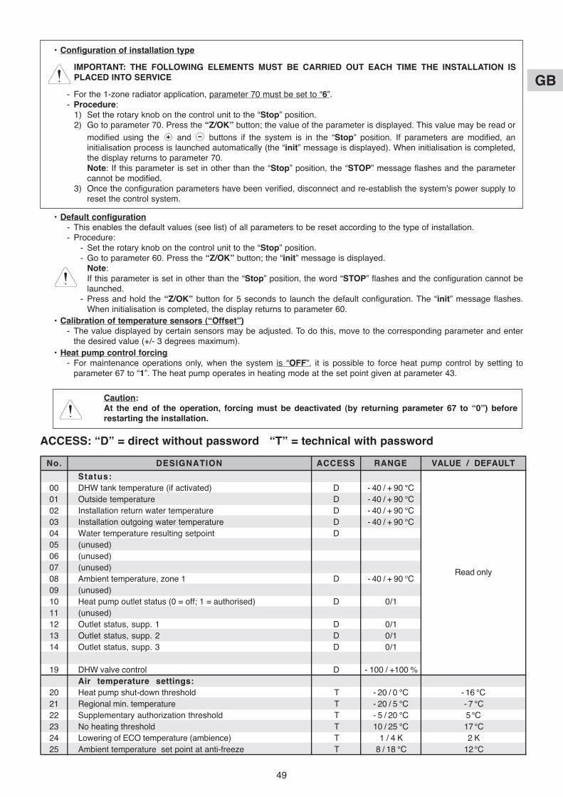
49
GB
Caution: At the end of the operation, forcing must be deactivated (by returning parameter 67 to “0”) beforerestarting the installation.
• Configuration of installation type
IMPORTANT: THE FOLLOWING ELEMENTS MUST BE CARRIED OUT EACH TIME THE INSTALLATION ISPLACED INTO SERVICE
- For the 1-zone radiator application, parameter 70 must be set to “6”.- Procedure:
1) Set the rotary knob on the control unit to the “Stop” position.2) Go to parameter 70. Press the “Z/OK” button; the value of the parameter is displayed. This value may be read or
modified using the and buttons if the system is in the “Stop” position. If parameters are modified, aninitialisation process is launched automatically (the “init” message is displayed). When initialisation is completed,the display returns to parameter 70.Note: If this parameter is set in other than the “Stop” position, the “STOP” message flashes and the parametercannot be modified.
3) Once the configuration parameters have been verified, disconnect and re-establish the system's power supply toreset the control system.
• Default configuration- This enables the default values (see list) of all parameters to be reset according to the type of installation.- Procedure:
- Set the rotary knob on the control unit to the “Stop” position.- Go to parameter 60. Press the “Z/OK” button; the “init” message is displayed.
Note: If this parameter is set in other than the “Stop” position, the word “STOP” flashes and the configuration cannot belaunched.
- Press and hold the “Z/OK” button for 5 seconds to launch the default configuration. The “init” message flashes.When initialisation is completed, the display returns to parameter 60.
• Calibration of temperature sensors (“Offset”)- The value displayed by certain sensors may be adjusted. To do this, move to the corresponding parameter and enter
the desired value (+/- 3 degrees maximum).• Heat pump control forcing
- For maintenance operations only, when the system is “OFF”, it is possible to force heat pump control by setting toparameter 67 to “1”. The heat pump operates in heating mode at the set point given at parameter 43.
ACCESS: “D” = direct without password “T” = technical with password
No. DESIGNATION ACCESS RANGE VALUE / DEFAULT
Status:00 DHW tank temperature (if activated) D - 40 / + 90 °C01 Outside temperature D - 40 / + 90 °C02 Installation return water temperature D - 40 / + 90 °C03 Installation outgoing water temperature D - 40 / + 90 °C04 Water temperature resulting setpoint D05 (unused)06 (unused)07 (unused)08 Ambient temperature, zone 1 D - 40 / + 90 °C09 (unused)10 Heat pump outlet status (0 = off; 1 = authorised) D 0/111 (unused)12 Outlet status, supp. 1 D 0/113 Outlet status, supp. 2 D 0/114 Outlet status, supp. 3 D 0/1
19 DHW valve control D - 100 / +100 %Air temperature settings:
20 Heat pump shut-down threshold T - 20 / 0 °C - 16 °C21 Regional min. temperature T - 20 / 5 °C - 7 °C22 Supplementary authorization threshold T - 5 / 20 °C 5 °C23 No heating threshold T 10 / 25 °C 17 °C24 Lowering of ECO temperature (ambience) T 1 / 4 K 2 K25 Ambient temperature set point at anti-freeze T 8 / 18 °C 12 °C
Read only

50
GB
Water temperature settings:26 Supplementary heating control hysteresis T 2 / P27 K 2 K27 Supplementary heating control lag T P26 / 6 K 3.5 K28 Heat pump control hysteresis - Unused T 1 / 4 K 3 K29 Water temperature setpoint in "anti-freeze" mode T 20 / 40 °C 35 °C30 Heating water max. temperature (Installation return) T 30 / 45 °C 40 °C31 (unused)32 Heating water min. temperature (nstallation return) T 25 / 35 °C 30 °C33 (unused)34 (unused)35 (unused)36 Thermodynamic heating authorization threshold (installation return) T 10 / 20 °C 15 °C37 Water outlet temperature max. alarm threshold T 60 / 90 °C 70 °C
Electric heater forcing (for maintenance only):40 Total electric heating capacity T 1 / 30 kW 6 kW41 Launch of the sequence T
Heat pump parameters:42 (unused)43 Maximum water temperature set point (return), heating T 40 / 50 °C 50 °C
Sensor offset:50 Outside sensor T + or - 3 K 051 Zone 1 air temperature sensor T + or - 3 K 052 (unused)53 Installation return water temperature sensor T + or - 3 K 054 Installation outlet water temperature sensor T + or - 3 K 0
57 Regulation reference temperature selection(1 = installation return point)
T Non-adjustable
1
Miscellaneous:60 Default configuration T61 TYPHONE language selection (1 = FR; 2 = GB) T 1/2 162 TYPHONE access code T 0/9999 123463 (unused)67 Heat pump forcing (active when off) T 0/1 068 (unused)
Configuration:70 Installation type T 1/6
1 = 1 Zone, floor2 = 2 Zones, floor3 = Unused4 = Mixed5 = Terminal units6 = 1 Zone radiators 6
71 (unused)75 Load shedding action (1 = closed contact = load shedding) T 0/1 176 CWC2 board activation (1 = Activated) T 0/1 1
Software versions:80 Control unit T81 Heating board T85 CWC2 board T
DHW :90 ECS board activation (0 = deactivated) T 0/1 0
Ambience setpoints: DCold setpoint: inactiveHeating setpoint zone 1 15 / 25 °C 20 °C
Direct accessKeypad
Read only
N° DÉSIGNATION ACCÈS PLAGE VALEUR / DÉFAUT

51
GB
9.7 - ALARMS• The alarms are indicated by a message flashing alternately on the display.
• Manual reset: by system shut-down after clearing the source of the fault.The heat pump alarms (Gr, FL) can also be reset by pressing the button on the CWC2 board or by disconnecting the powersupply.
• Automatic reset: the alarm disappears when the source of the fault is corrected.• Note:
The alarms are displayed even if the system is shutdown.If several alarms occur simultaneously, the various codes are displayed alternately.
(*) The exact nature of the heat pump alarm can be known by connecting the specific maintenance keypad display to theheat pump.
(**)Overheat security with manual reset on the body of the heater. See the heat pump's installation instructions.
ALARM CODE ACTION NTR (nothing
to report)
Heat pump fault Gr (*) In heating mode: Manu.
Supplementary heating load shedding prohibited.
In Anti-freeze mode:
Supplementary heating load shedding prohibited.Heater fault HE Prohibits supplementary heating operation. Auto (**)
Installation returnwater sensor faultInstallation outletwater sensor fault
Water flowrate fault FL Prohibits supplementary heating operation (and the heat pump). Manu.
Suppression of the supplementary heating authorizationthreshold according to the outside temperature.
Automatic switching to Anti-freeze Mode if case of a fault(indicated by the absence of the bar graph).
Restart in the heating mode selected by pressing and holdingthe "OK" button. This acknowledgement is stored in memoryand signalled by the "coin" icon which is displayed as long asthe generator failure is present.
Communication or systemfault
Cn System shut-down
Outside air sensor fault SAE System shut-down
Ambience sensor faultzone 1
System shut-down
Auto
Auto
Auto
Auto
Auto
SEIn
Manu.
Suppression of the supplementary heating authorizationthreshold.
Max. water outlettemperature fault(Adjustable threshold 70°C,parameter 37)
tE System shut-down
SA1 System shut-down
System shut-down
SEOu

52
GB
9.8 - HYDRAULIC SCHEMATIC DIAGRAM
Flo
wre
gula
tor
(acc
esso
ry) M
ixin
g ta
nk(a
cces
sory
)
Do
not
use
ther
mos
tatic
val
ve o
n ra
diat
ors
whi
ch a
re in
stal
led
in t
he s
ame
room
as
the
cont
rol u
nit.
Wat
er P
ump
(per
man
ent
oper
atio
n)
not
supp
lied
Rad
iato
rs
Ele
ctric
heat
er
70 L
PH
RIE
Rad
iato
rs
Rad
iato
rs
Dis
char
geva
lve
(not
supp
lied)
Sys
tem
boar
d
Installation is to be performed in compliance withestablished trade practices and current standards.
Note:For easy understanding, all isolation valves are notindicated on this drawing.
See accessories table.O
utdo
or s
enso
r(s
uppl
ied
with
sys
tem
cont
rol k
it K
60D
070Z
)
In L
ine
Str
aine
r(s
uppl
ied
with
PH
RIE
)
Dirt
sep
arat
or(a
cces
sory
)
Wat
erou
tlet
sens
ors
Wat
er in
let
sens
ors
Sys
tem
con
trol
kit
K60
D07
0Z(S
uppl
ied
in a
cces
sory
)C
omm
unic
atio
n lin
e
Pum
p
53
GB• Only 1 zone Radiators application.• Function performed by the ECS board installed in the DHW tank control box.
Note:The board micro-switch must be switched to “ON” and parameter 90 set to “1” in order to activate the function.
10.1 - PRINCIPLE (see hydraulic schematic diagram in § 10.6.)• A three way ON/OFF valve (spring return) controlled by the ECS board allows the hot water produced by the heat pump:
- either into the radiator circuit to heat the installation,- or to an exchanger located in the domestic hot water tank during an DHW cycle controlled by the ECS board.
10.2 - OPERATION• If the probe located in the DHW tank detects a temperature lower than a predetermined threshold = 35°C, a thermodynamic
DHW heating cycle is triggered:- DHW valve is activated,- the heat pump is forced in heating mode (see detail below),- the electrical supplementary heating is forbidden,- the DHW tank electrical heating is forbidden.- start-up of the heating circulating pump if stopped.
• The user is alerted to a DHW cycle by the pictogram displayed on the control unit.• An DHW cycle stops in each of the following circumstances:
- when the temperature read by the DHW tank probe exceeds an adjustable threshold on parameter 91,- when an DHW heating cycle reaches the maximum time adjustable on parameter 93,- when the average difference (calculated over 15 minutes) between the water inlet temperature in the exchanger and the
temperature in the tank is lower than a value which can be adjusted by parameter 92. This indicates that the heatexchange is not sufficient,
- when the system is switched to “OFF”,- when the system triggers an alarm (except the “HE” backup default or when the heat pump is in safe mode (based on
the water return temperature or the outside temperature).• The stop sequence for an DHW cycle is the following:
- the DHW valve is deactivated,- the heat pump and its electrical backup are controlled normally again by the heating system,- electric tank heating is authorized again.- shut-down of the heating circulating pump, if needed (see below).
• Safety time delay: the minimum time between two cycles is five hours. This time delay is either activated at the end of acycle, or by “OFF”. The time delay is not activated if a system alarm is triggered (excluding “VA”).
• Heating system circulating pump control:- in “OFF” mode , circulating pump stopped,- in “Summer” mode, controls the circulating pump only when the DHW valve is activated (this prevents hot water from
the system from being sent to the radiators, after a DHW cycle). Circulator start-up is delayed 20 seconds,- in “Heating” mode (Comfort, Eco or Anti-freeze), controls the circulating pump if the outside temperature is below the
non-heating temperature threshold or if the DHW valve is activated,- a degripping device actuates the circulating pump for 3 seconds every 24 hours when not in operation.
• Forcing of the heat pump in DHW mode:- the heat pump operates using the following set point values:
- in heating mode, the value of parameter 43,- in “SUMMER” mode (DHW alone), the value given at parameter 43 reduced by 5 K.
With the DHW function, it is recommended that P43 be set at 50°C.
10.3 - TIMER PROGRAMMING• The DHW cycle triggering mode can be selected using parameter 94:
- either free mode with no programmed time slots via tank probe temperature detection,- or timer mode with the possibility of programming 1 or 2 one-hour time slots during which the tank is analysed and a
cycle can be triggered. Parameters 95 and 96 correspond to the start time for each time slot.
10 - DOMESTIC HOT WATER (DHW) PREPARATION OPERATION

54
GB
• Forced outlet: - Possibility (when stopped) to force the valve control to DHW position (Y1) and the circulating pump position (Y2) using
parameter 97.- At the end of the forcing operation, forcing must be deactivated (by returning parameter 97 to “0”).
After deactivation, the message “UA” is displayed for approximately 3 minutes. Wait for this message todisappear before restarting the system.
• Note:If the ECS board is activated by parameter 90, you are advised to switch off power to the whole system and then switchback on again to ensure regulation is reinitialised.
No DESIGNATION ACCESS RANGE VALUE / DEFAULT
Software version:84 ECS board T Read only
DHW :90 Board present T 0/1 091 Tank temperature threshold for DHW cycle interruption T 40 / 60 °C 45 °C92 Exchanger/tank water inlet temperature difference threshold T 4 / 8 K 4 K93 Maximum DHW cycle time T 0.5 / 2 H 1 H94 Programming (0 = without ; 1 = 1 cycle / d ; 2 = 2 cycles / d) T 0/1/2 095 Time slot 1° cycle T 0/23 H 1 H96 Time slot 2° cycle T P95+P93+5/23H 12 H97 Forcing outputs OFF (DHW valve + circulating pump) T 0/1 098 DHW tank temperature D - 40 / 90 °C99 DHW exchanger water inlet temperature D - 40 / 90 °C
Read only
10.4 - ALARM• The DHW pictogram on the control unit display flashes and indicates that thermodynamic DHW heating is not available for
the following reasons:- the board micro-switch is set to “OFF”,- communication fault,- loss of power supply to the board,- faulty temperature probe (tank or water inlet).
• The ECS board goes into fallback:- DHW valve control stops,- tank electric heating forbidden output deactivated,- PAC (heat pump) forcing signal stops,- circulating pump activated (priority to the heating system).
• A positioning fault of the DHW valve causes the DHW cycle to stop and a specific alarm to be triggered (see § 9.7).
10.5 - SPECIFIC PARAMETERS• See general points in § 9.6.

55
GB
10.6 - HYDRAULIC SCHEMATIC DIAGRAM
Mix
ing
Tank
70 L
(acc
esso
ry)
D.H
.WK
IT‘’K
PEC
S’’
Do
not
use
ther
mos
tatic
valv
e on
ra
diat
ors
whi
char
e in
stal
led
in t
he s
ame
room
as
the
cont
rol u
nit.
Ele
ctric
al b
ox E
CS
boar
d (s
uppl
ied
with
DH
W k
it)
3 w
ays
valv
e(s
uppl
ied
with
DH
W k
it)
Exc
hang
er w
ater
inle
tte
mpe
ratu
re s
enso
r (s
uppl
ied)
Wat
er t
ank
tem
pera
ture
sens
or (
supp
lied)
Ele
ctric
alsu
ppor
the
ater
(sup
plie
d)
DH
W k
it“K
PE
CS
”
Wat
er o
utle
t
Wat
er in
let
Saf
ety
valv
e (s
uppl
ied
with
DH
W t
ank)
Com
mun
icat
ion
line
DHW Kit KPECS includes:- DHW Tank with electrical support heater 3 kW.- Electrical control box + 2 sensors.- 3 ways valve for DHW preparation.- Safety valve 7 bar.- Check valve.
Note:DHW must be realised in conformity with normativesrecommendations.
Mix
ing
tank
(acc
esso
ry)
Pum
p (n
ot s
uppl
ied)
Ele
ctric
heat
er
70 L
PH
RIE
Dis
char
geva
lve
(not
supp
lied)
Rad
iato
rs
Che
ck v
alve
(sup
plie
d w
ith
DH
W k
it)
Ele
ctric
alhe
ater
supp
ly
Installation is to be performed in compliance withestablished trade practices and current standards.
Note:For easy understanding, all isolation valves are notindicated on this drawing.
See accessories table.
Sys
tem
boar
d
Out
door
sen
sor
(sup
plie
d w
ith s
yste
mco
ntro
l kit
K60
D07
0Z)
In L
ine
Str
aine
r(s
uppl
ied
with
PH
RIE
)
Dirt
sep
arat
or(a
cces
sory
)
Wat
erou
tlet
sens
ors
Wat
er in
let
sens
ors
Flo
wre
gula
tor
(acc
esso
ry)
Sys
tem
con
trol
kit
K60
D07
0Z(S
uppl
ied
in a
cces
sory
)
Flo
wre
gula
tor
(acc
esso
ry)
Rad
iato
rs
Com
mun
icat
ion
line
Pum
p

56
GBCWC2 communication and control board is mounted inside the heat pump. It is connected to the system control by means of theBUS communication line.It ensures 3 functions:
- Communication interface between system control and heat pump control.- Management of the heat pump heat exchanger and water circulating pump.- Possible base de-ice electric heater control.
A set of button/micro-switches/lights takes place on the board.
11 - CWC2 CONTROL BOARD PRESENTATION
NN
OC
RC
SC
CWC2
PPCDHPPU N
TW2TW1E1E2TFS E2P
PP
DH
PPC
W
AL
SYS
RC
123
DISP
CHK
123
POWER
Power light
Water flow light- OFF = no water flow- ON = water flow- Blinking = water flow alarm
Forced operation light:- Blinking green = ON- Blinking red = OFF
Forced operation light:- Blinking green = Cool- Blinking red = Heat
Maintenancekeyboard/display light
System communicationlight
Configurationmicro-switches
Reset push button for: - Heat pump alarms reset.- Water circulating pump forced operation.
Heat pump alarm light:- Blinking if automatic reset.- Steady if manual reset.
De-ice heater control light
Water circulating pump speed control light
Water circulating pumpcontrol
11.1 - COMMUNICATION FUNCTION11.1.1 - SIGNALS SENT BY THE SYSTEM TO THE HEAT PUMP
• Stop/authorisation.• Heating/Cooling operating mode.• Temperature operating setpoints (installation outgoing water).
11.1.2 - HEAT PUMP ALARM SIGNALS FOR THE SYSTEM• “Gr” alarm:
Generated in the event of a water flow fault (see paragraph 11.2) or a heat pump fault.Heat pump faults are classified in 2 categories:
- Manual reset faults:Stored by the board when they appear. The board's alarm light comes on steady.
- Automatic reset faults:The board's alarm light blinks.The fault is stored in the board's memory only if it lasts longer than 30 minutes. The alarm light then remains steadyand the “Gr” alarm is sent to the system.
The detailed list of faults is provided in the maintenance manual.To determine the exact nature of the fault, refer to LED1/LED2 on the power board, item A3 or connect the specificmaintenance keypad/display unit to the heat pump. (see maintenance manual).

57
GB
11.2 - WATER CIRCULATION MANAGEMENT• Circulator control:
- In heating mode, actuated if the outside temperature is less than the non-heating temperature.- In cooling mode, actuated as soon as the mode is selected.- By forcing during maintenance operations (see paragraph 11.4). Forcing is activated or deactivated by pressing and
holding (5 seconds) the board control button. Forcing is indicated by the blinking of the circulator indicator light.The shutdown of the circulator is delayed for 3 minutes (but immediate in the case forcing is stopped or a flow fault).If the pump is stopped, it can be restarted by 3 functions:
- “Anti-sticking”: automatic operation for 5 seconds every 24 hours.- “Anti-freeze”: function activated by setting micro-switch SW1-1 to “ON” (delivery default setting). The pump is started if
outside temperature is below 0°C.- “Forcing”.
• Monitoring of water flow:When the circulator is in operation, a lack of water flow longer than 10 seconds will cause the heat pump to stop. The alarmlight “AL” blinks. If the lack of water flow continues for more than one minute (or if it happens more than 3 in the last hour),the water flow fault is stored in memory:
- the alarm light “AL” then remains on steady, - the circulator stops,- the “FL” alarm has to be sent to the system, for that, the micro-switch SW1-2 must be set to “ON”.
The alarm is reset by pressing the “RESET” button, or turning the system “OFF”, or by disconnecting the power.
• Water circulating pump speed control:Allows to drive the water circulating pump speed according heatpump operation conditions by means of output signal “PPC”.The type of this output is either “PWM” or “0/10V” according thetype of the water pump:
- “PWM” configuration: - Jumper “JPC” on “1-2”.- Micro-switch “SW2-2” on “OFF”.
- “0/10V” configuration: - Jumper “JPC” on “2-3”.- Micro-switch “SW2-2” on “On”.
This speed control function is activated by setting micro-switch “SW2-1” on “ON” (delivery default setting = “OFF”).
11.3 - DE-ICE HEATER CONTROLActivated in heating mode only for a 30 minutes cycle if the heat pump starts a defrost sequence with a outdoor temperaturelower than 0°C.
11.4 - STAND-ALONE OPERATION OF THE HEAT PUMP (Off-system)For the maintenance and commissioning operations, the heat pump can be operated in a stand-alone configuration,off-system, using the specific maintenance keyboard / display.The system can be disconnected in two ways: - Either, with power off, disconnect the system communication line “BUS” from CWC2 board.- Or, by the system control unit, deactivate heat pump control by setting parameter 76 to “0”.
Note: All changes made to parameter 76 will result in an initialisation of the control and cause all parameters toreturn to their default value.When the heat pump control is reactivated, a new parameterisation operation corresponding to theinstallation must performed.
To operate the heat pump, force the circulator before initiate an order via the specific maintenance keyboard/display unitcommand.Consult the maintenance manual.Note:Inputs for external contacts are available on CWC2 border in order to force heat pump operation (ON/OFF - HEAT/COOL).These inputs have priority to the control signals initiated by means of the keyboard/display. A voltage free change-over contact (use in 24 V max.) is available on CWC2 board for remote heat pump alarm signalization.For all details, please consult the maintenance contact.
NOT ACTIVATED ONTHIS VERSION

58
GB Use in heating mode only
• A DELTA-DORE TYPHONE 500 type telephone control unit can be connected to the communication line (BUS) (availablefrom DELTA-DORE distributors).Consult the manual supplied with the telephone control.
• By calling the telephone line on which the TYPHONE is recorded, the user can:- know the ambient temperature of zone 1,- know the setpoint temperature of the current mode of zone 1,- send an override setpoint.
In case of setpoint modification, zone 1 thus operates in “COMFORT” mode with the new setpoint.This override is indicated by an index on the LCD.Any action on the rotary knob deactivates the override and extinguishes the indicator.
• Parameters possibilities: - access code change (parameter 62),- interface language change - French / English (parameter 61).
12 - TELEPHONE CONTROL

59
GB

F
GB
D
P
I
E
P
1958

F
GB
D
P
I
E
P

F
GB
D
I
E
P
Par souci d'amélioration constante, nos produits peuvent être modifiés sans préavis.Due to our policy of continuous development, our products are liable to modification without notice.
Per garantire un costante miglioramento dei nostri prodotti, ci riserviamo di modificarli senza preaviso.En el interés de mejoras constantes, nuestros productos pueden modificarse sin aviso prévio.
Unsere Produkte werden laufend verbessert und können ohne Vorankündigung abgeändert werden.Com o objectivo de uma melhoria constante, os nossos produtos podem ser modificados sem aviso prévio.
R.D. 28 Reyrieux BP 131 01601 Trévoux CEDEX FranceTél. 04 74 00 92 92 - Fax 04 74 00 42 00Tel. 33 4 74 00 92 92 - Fax 33 4 74 00 42 00R.C.S. Bourg-en-Bresse B 759 200 728