DRS Final Report
36
A Drag Reduction System developed for the Formula SAE
-
Upload
santiago-napal-laguna -
Category
Documents
-
view
38 -
download
0
Transcript of DRS Final Report

A Drag Reduction System developed for the Formula SAE

Members
Advisor
George Youssef, Ph.D. Professor Mechanical Engineering
Sponsors

INDEX
INTRODUCTION AND BACKGROUND
DESIGNING CONSIDERATIONS
DRS SYSTEM DESIGN
AERODYNAMIC STUDY ACTUATION TYPE STRUCTURE DESIGN AND SIZING ELECTRIC AND ELECTRONIC DEVICES
STEERING WHEEL DESIGN
CONCEPT DEFINITION PROTOTYPE FORCE ANALYSIS FINAL DESIGN
CONCLUSIONS AND CONSIDERATIONS
REFERENCES

Introduction & background The aim of this paper is to describe the whole process and details of our DRS project. Our team is made up of three international students coming from Spain, Pablo (Product design engineering), Santiago Napal (Mechanical engineering) and Unai Echegaray (Mechanical engineering). We all share the same passion: The racing/motorsport world. The idea for our project came when we realized that there was an engineering team called “Aztec Racing”. After some prior research on the FSAE world and some conversations with team members we scheduled a meeting with the director. We made him some proposals to improve the current car and we finally decided that a Drag Reduction System (DRS) would be the most useful one. The importance of reducing the drag directly affects on the car's performance on acceleration and maximum speed. To briefly summarize why the DRS would be an important improvement, we have to analyze the aerodynamic impact when racing. On one hand, downforce is extremely important to keep the car stuck to the ground and avoid slippage, especially while turning. But on the other hand, it is not possible to increase downforce without increasing drag force, what reduces acceleration in straight line. In conclusion, the car needs different requirements depending on the circuit section. The DRS allows to vary the aerodynamic forces, maintaining downforce while turning and reducing drag while driving in straight line. Our final concept was to made a whole pack of Steering wheel+DRS considering the necessity of controlling the system from the steering wheel. Furthermore, the steering wheel they were using was not upgradable, so it didn’t allow to integrate any electronics. The aim of the steering wheel is, not only to incorporate the DRS's push button, but allow the introduction of new electronics in the future. The main specifications for the DRS system are that it has to be fast, light, cost effective, aerodynamic friendly and meet the FSAE requirements. For the steering wheel, the design has to be light, ergonomic, upgradable and also meet the FSAE requirements.

Designing Considerations In an effort to improve the aerodynamics of the car, we thought about several possibilities. In 2013 the Aztec Racing implemented the rear wing. This improvement leaded to better results in circuit trials of the following years. However, this new device increased the drag force, leading to a worse result in the acceleration trial. Using the current Formula 1 knowledge, we realized the DRS system would not only improve the car's straight acceleration, but also vary the forces depending on the track shape. The first questions we thought about were: When is the spoiler going to change the position? Who or what is going to control the mechanism? What grade of automatization do we need? How professional teams do it? To answer the first question, we realize that the requirements of traction and drag are directly related to the track shape, so the position will change whenever the track changes. It will be activated (open position) in straight line and it will be deactivated (close position) before turning. The system can be controlled by the driver, it can be completely automatic or it can combine both systems. The main target about doing it automatic is avoiding distractions of the driver. However, the parameters to do it automatic are diffuse. That is why we thought combining manual control and sensors. When a corner is approaching, the driver is going to be focused on braking, downshifting and following the drawn, so it would be better if the system can deactivate itself. Taking advantage of the brake detection that the car currently uses we can use that signal to turn the system off, so the driver doesn’t have to care about pressing the button. Nevertheless, when the driver is driving in straight line, he only has to accelerate, so he can decide if he activates the system if it’s worth it. Furthermore, doing the activation automatic is complex. Not only acceleration can be taken as reference, also G forces to detect turning and steering wheel sensors must be measured. To solve this problems, we thought about the last question in the list. The formula 1 uses manual actuation because they find more reliable the precision of the driver rather than the accuracy of accelerometers and other sensors. The manual actuation needs, obviously, a push button to be pressed when desired. The best place to set the button is the steering wheel, so the driver doesn’t need to take the hands out of it. However, the current steering wheel is not upgradable. Luckily, Pablo, our Product Design engineer has the knowledge to design an ergonomic and upgradable shape for this device. This, with the knowledge of our two mechanical engineers enables the team to create a new and efficient steering wheel.
DRS SYSTEM DESIGN
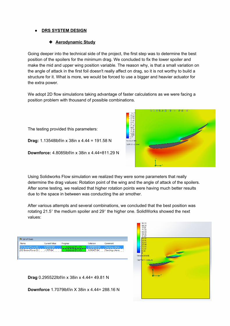
Aerodynamic Study Going deeper into the technical side of the project, the first step was to determine the best position of the spoilers for the minimum drag. We concluded to fix the lower spoiler and make the mid and upper wing position variable. The reason why, is that a small variation on the angle of attack in the first foil doesn't really affect on drag, so it is not worthy to build a structure for it. What is more, we would be forced to use a bigger and heavier actuator for the extra power. We adopt 2D flow simulations taking advantage of faster calculations as we were facing a position problem with thousand of possible combinations. The testing provided this parameters: Drag: 1.13548lbf/in x 38in x 4.44 = 191.58 N
Downforce: 4.8085lbf/in x 38in x 4.44=811.29 N
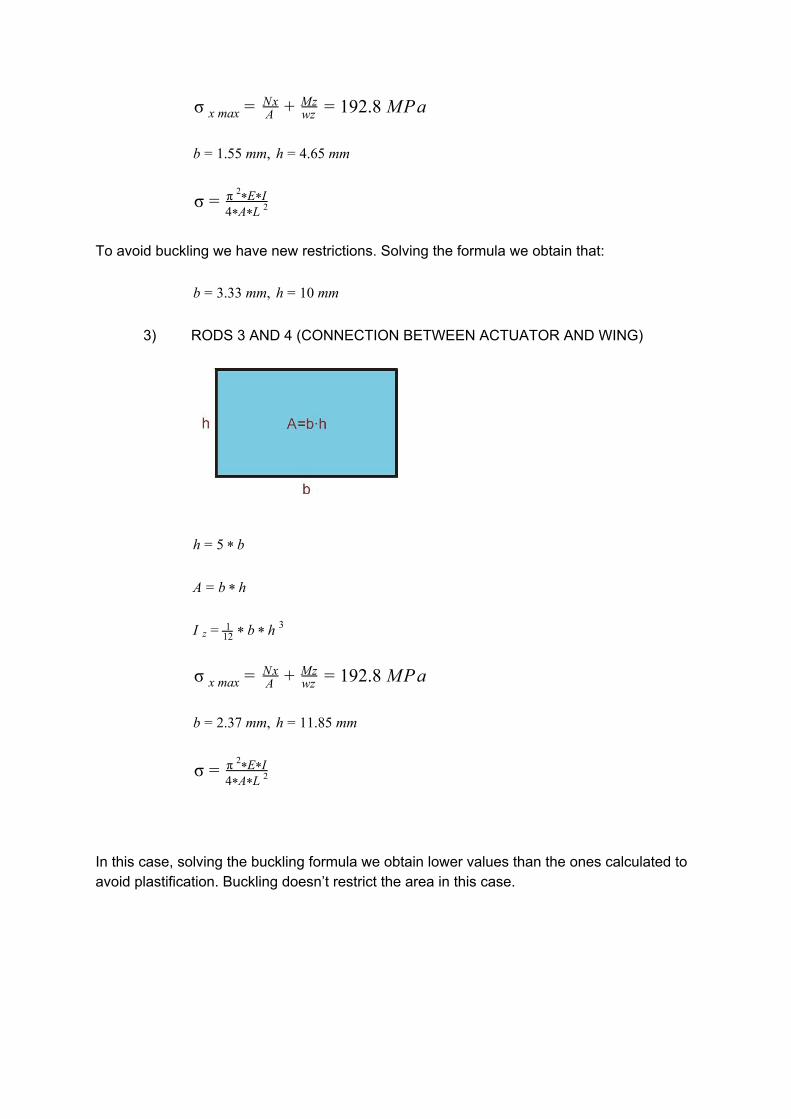
Using Solidworks Flow simulation we realized they were some parameters that really determine the drag values: Rotation point of the wing and the angle of attack of the spoilers. After some testing, we realized that higher rotation points were having much better results due to the space in between was conducting the air smother. After various attempts and several combinations, we concluded that the best position was rotating 21.5° the medium spoiler and 29° the higher one. SolidWorks showed the next values:
Drag 0.295522lbf/in x 38in x 4.44= 49.81 N
Downforce 1.7079lbf/in X 38in x 4.44= 288.16 N

Comparing this results with the ones tested on closed position, we can clearly bear out our first assumptions. The drag dramatically decreases and the ratio with the downforce stayed auspicious as the reduced amount was greater in the drag. Tested aerodynamic improvements:
Reduced drag percentage = 74.66 %
Reduced downforce percentage = 64.49 %
Actuation type
When we thought about moving objects under certain forces only pressing a button, we had to think what kind of actuation fits best our requirements. The main four actuation types are: electric, pneumatic, hydraulic and mechanic. The last two ones were discarded due to the excessive weight. In order to decide which actuation will be chosen we are going to compare the next features: Weight, actuation speed, cost and Formula SAE regulations.
Cost: When we talk about cost, we need to consider not only all the devices, but also the manufacturing techniques. Electric actuators become expensive when we look for fast motion and light weight. However, pneumatic devices are cheaper. Nevertheless, the pneumatic actuation requires more devices, including an electro valve, an air compressed tank and braided hose.
Weight: This feature is similar in both systems. the electric actuators are heavier than pneumatic ones, but summing all the pneumatic components the overall weight of the pneumatic version overcomes the electrical.
Actuation Speed: This feature is controversial. Both systems can be extremely fast if you are willing to pay the price. While it is true that all pneumatic systems are fast using MediumHigh speed, electric systems are normally slow. Electric actuators designed for racing are necessary to be fast enough.
FSAE regulations: The regulations are not tight in electrical devices. However, it is hard to achieve all the pneumatic regulations, especially those related to the air compressed. Due to the places to set the tank and how the car is designed, the only available place was really close to the exhaust system. The high temperatures pose a risk.
Considering all this, we determined that electric actuation fits best our requirements. The budget for the Aztec Racing is wider than other years, so they can afford the extra cost of the electric actuator and we can avoid the danger of tank explosions.

Once it has been determined, we can go ahead and do the scheme. As explained in the designing considerations, we are going to have manual actuation, but we are also going to consider brake detection to deactivate the system. In order to inform the driver if the system is activated, the push button will have a LED that will be switched on when the DRS is activated. All this parameters will be controlled by a microcontroller. The team is already using the arduino family for the electronics, so we will use the same devices. Generally, the arduino will have two inputs (Push button and brake switch) and two outputs (LED and electric actuator). The code will be posted at the end, in the electronics section.
Structure design and sizing
The Structure has the purpose of placing the upper and mid wing in the position of less drag that has been determined in the aerodynamic analysis. The first step was fixing the geometry. To do that we used Solidworks.
Figure: Closed position.
Figure: Open position.
After having the geometry we could run it in a FEA program under the aerodynamic forces and determine the force necessary to move the wing. In other words, the force that the actuator needs provide. It also determines the axial force and bending moment that each rod has to resist.

The program we used for this is called MEFI. It was developed in Spain and it allows to combine distributed forces and imposed movements.
Figure: MEFI Forces.
Figure: Bending Moment Figure: Axial Forces.
With this values and using material resistance theory, we can calculate the area necessary to resist the forces and avoid buckling. We always design for the worst scenario, that is why we take the highest axial force and bending moment per rod and we use that value to do the calculation byhand.
MATERIAL: Aluminium 6061T6. Yield Stress: 241 MPa Elastic Modulus: 70 GPa
ADHESIVE: 3M Composite Adhesive. Overlap Shear Strength: 25.97 MPa
SAFETY FACTOR. 1.25

1) FEMALE END ROD
.3R = 2 * r
R ) .62 0 m A = π * ( 2 − r 2 = 8 * 1 −6 2
R ) .67 0 m I z = 4π * ( 4 − r 4 = 8 * 1 −12 4
80 MPa σ x max = ANx + wz
Mz = 4
.8 mm, R .84 mm r = 0 = 1
σ = π E I2* *4 A L * * 2
To avoid buckling we have new restrictions. Solving the formula we obtain that:
.008 mm, R .31 mmr = 1 = 2
However, to fit in the actuator bar, it will have to be oversized. With this calculations we know that we can choose the smaller end rod that fits in the main rod.
2) ROD 2 (CONNECTION BETWEEN WINGS)
h = 3 * b
A = b * h
I z = 112 * b * h
3
92.8 MPa σ x max = ANx + wz
Mz = 1
.55 mm, h .65 mm b = 1 = 4
σ = π E I2* *4 A L * * 2
To avoid buckling we have new restrictions. Solving the formula we obtain that:
.33 mm, h 0 mmb = 3 = 1
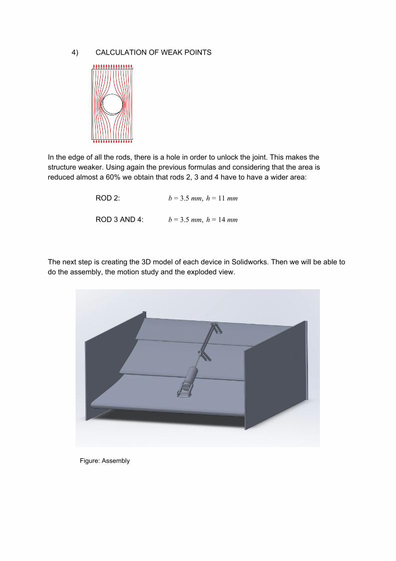
3) RODS 3 AND 4 (CONNECTION BETWEEN ACTUATOR AND WING)
h = 5 * b
A = b * h
I z = 112 * b * h
3
92.8 MPa σ x max = ANx + wz
Mz = 1
.37 mm, h 1.85 mmb = 2 = 1
σ = π E I2* *4 A L * * 2
In this case, solving the buckling formula we obtain lower values than the ones calculated to avoid plastification. Buckling doesn’t restrict the area in this case.
4) CALCULATION OF WEAK POINTS
In the edge of all the rods, there is a hole in order to unlock the joint. This makes the structure weaker. Using again the previous formulas and considering that the area is reduced almost a 60% we obtain that rods 2, 3 and 4 have to have a wider area:
ROD 2: .5 mm, h 1 mmb = 3 = 1
ROD 3 AND 4: .5 mm, h 4 mm b = 3 = 1
The next step is creating the 3D model of each device in Solidworks. Then we will be able to do the assembly, the motion study and the exploded view.
Figure: Assembly
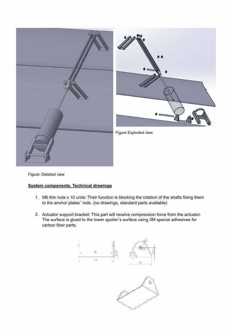
Figure Exploded view
Figure: Detailed view
System components. Technical drawings
1. M6 thin nuts x 10 units: Their function is blocking the rotation of the shafts fixing them to the anchor plates´ rods. (no drawings, standard parts available)
2. Actuator support bracket: This part will receive compression force from the actuator. The surface is glued to the lower spoiler´s surface using 3M special adhesives for carbon fiber parts.

3. Actuator housing: The actuators cover to perfectly fit the cylinder and enabling the rotation due to the incorporated drilled extension where is build.
4. Threaded shaft x 3 units: (no drawings, standard parts available) 5. Extended rod end 6. Klicktronic actuator: Electric actuator to supply an instant movement. 7. Connecting rods

8. Anchor plate (medium spoiler, named 3): Junction structure between the extended end rod that enables to transform the linear movement into rotation of the wing.
9. Anchor plate (Higher spoiler, named 4): Junction structure between the rods that enables to transform the linear movement into rotation of the higher wing.
10. Spacer: To block the axial displacement of the rods that are connecting medium and high spoilers (no drawings, standard parts available).

Electric and Electronic devices
Arduino Uno R3
This is the microcontroller they currently use. The program to control the system is simple, so we can implement it with a longer one and avoid using a new one. This microcontroller also includes a DigitalAnalog Converter, what can be use for other purposes such as taking information of the engine and develop a launch control system. The code is the following:
void setup() pinMode(1, INPUT); pinMode(2, INPUT); //Así se inicializa void loop () //Igual que while(1) enumDRSon,DRSoff DRSstate=DRSoff; switch (DRSstate) //PORTD usa pins 07. case DRSoff: PORTD = B11111010; if ((digitalRead(1) == HIGH)) //if the brake is not pressed if ((digitalRead(2) == LOW)) DRSstate=DRSon; //if the pushbutton is pressed break; case DRSon: PORTD = B00000101; if (((digitalRead(1)) == LOW)||((digitalRead(2)) == 0)) DRSstate=DRSoff; //if pushbutton or brake are pressed break;

Momentary Push Button
The Button implemented in the steering wheel will be a Normallyopen momentary pushbutton. This will send a pulse to the arduino. It will also include a LED light to let the driver know the state of the system, so it’s at the same time an input and an output of the system.
Brake Light Switch
In order to detect brake we are going to use the pedal they already use to switch on the brake light when braking. In our case, the purpose will be sending a signal to the arduino to deactivate the system immediately.
Electric Actuator
The actuator chosen is a Klicktronic device. The reasons are the high speed of actuation and the forces it can apply. This actuator was originally design for paddle shifters, and in fact, is the one selected by the paddle shifter team to use in the car for the following year.
STEERING WHEEL DESIGN
CONCEPT DEFINITION Designing a steering wheel for the Formula SAE’s car is the second part of this project. The idea was to design a new steering wheel that improves the capabilities of the car. Being able to activate the DRS system through a button and leaving the team with a blank sheet for further installation of electronics to control and monitor the car. In order to get satisfactory results, we started listing a set of specifications that we had to accomplish: The new steering wheel had to be light, ergonomic, with push button implemented and meet FSAE’s requirements (shape & attaching system). FSAE requirements: T6.5.4 The steering wheel must be attached to the column with a quick disconnect. The driver must
be able to operate the quick disconnect while in the normal driving position with gloves on.
T6.5.6 The steering wheel must have a continuous perimeter that is near circular or near oval, i.e. the
outer perimeter profile can have some straight sections, but no concave sections. “H”, or cutout
wheels are not allowed.
T6.5.7 In any angular position, the top of the steering wheel must be no higher than the topmost
surface of the Front Hoop.
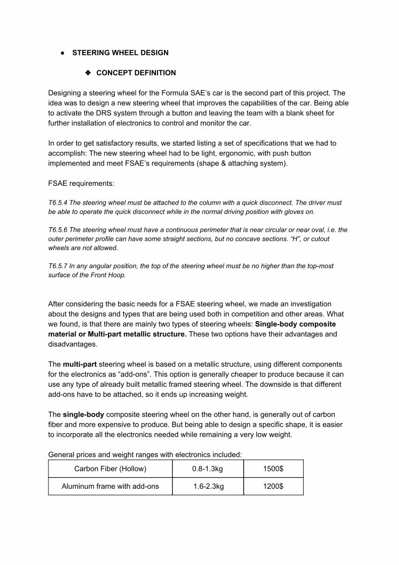
After considering the basic needs for a FSAE steering wheel, we made an investigation about the designs and types that are being used both in competition and other areas. What we found, is that there are mainly two types of steering wheels: Singlebody composite material or Multipart metallic structure. These two options have their advantages and disadvantages. The multipart steering wheel is based on a metallic structure, using different components for the electronics as “addons”. This option is generally cheaper to produce because it can use any type of already built metallic framed steering wheel. The downside is that different addons have to be attached, so it ends up increasing weight. The singlebody composite steering wheel on the other hand, is generally out of carbon fiber and more expensive to produce. But being able to design a specific shape, it is easier to incorporate all the electronics needed while remaining a very low weight. General prices and weight ranges with electronics included:
Carbon Fiber (Hollow) 0.81.3kg 1500$
Aluminum frame with addons 1.62.3kg 1200$
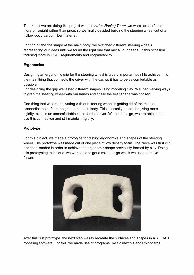
Thank that we are doing this project with the Aztec Racing Team, we were able to focus more on weight rather than price, so we finally decided building the steering wheel out of a hollowbody carbon fiber material. For finding the the shape of the main body, we sketched different steering wheels representing our ideas until we found the right one that met all our needs. In this occasion focusing more in FSAE requirements and upgradeability. Ergonomics Designing an ergonomic grip for the steering wheel is a very important point to achieve. It is the main thing that connects the driver with the car, so it has to be as comfortable as possible. For designing the grip we tested different shapes using modeling clay. We tried varying ways to grab the steering wheel with our hands and finally the best shape was chosen. One thing that we are innovating with our steering wheel is getting rid of the middle connection point from the grip to the main body. This is usually meant for giving more rigidity, but it is an uncomfortable piece for the driver. With our design, we are able to not use this connection and still maintain rigidity. Prototype For this project, we made a prototype for testing ergonomics and shapes of the steering wheel. The prototype was made out of one piece of low density foam. The piece was first cut and then sanded in order to achieve the ergonomic shape previously formed by clay. Doing this prototyping technique, we were able to get a solid design which we used to move forward.
After this first prototype, the next step was to recreate the surfaces and shapes in a 3D CAD modeling software. For this, we made use of programs like Solidworks and Rhinoceros.

Material The material is the crucial part of the steering wheel, it is what makes our design possible. What we finally chose is a carbon fiber composite. Having the advantage of being sponsored by some carbon fiber companies as the 3M glue company, our final composite composition was predicted by using some of their materials. After some research, we defined the T300300 carbon fibers and the 35016 epoxy resin as the best solution for our application. The desired mixture was compounded by 60 wt % carbon fiber and 40 wt % of epoxy resin. For the next step, the composite predicted properties, we used the Autodesk Simulation software that enables to get the values of any specific composite mixture. We set all the required properties we found from the independent materials and calculate the mixture values. Later on, this properties were implemented in the SolidWorks simulation software willing to create a personalized composite as exactly defined by Autodesk. Some previous setup was required, such as, defining the material as linear orthotropic.
Property Value Unit
Elastic modulus X 20249300 psi
Elastic modulus Y 1283260 psi
Elastic modulus Z 1283260 psi
Poisson coefficient XY 0.2522
Poisson coefficient YZ 0.2522
Poisson coefficient XZ 0.3611
Shear modulus XY 657430 psi
Shear modulus YZ 657430 psi
Shear modulus XZ 493493 psi
Mass density 0.06 lb/inch
Tensile strength X 307190 psi
Tensile strength Y 8749 psi
Compression strength X 189796 psi
Compression strength Y 31701.3 psi
Shear strength XY 6118 psi
Elastic strength 230000 psi
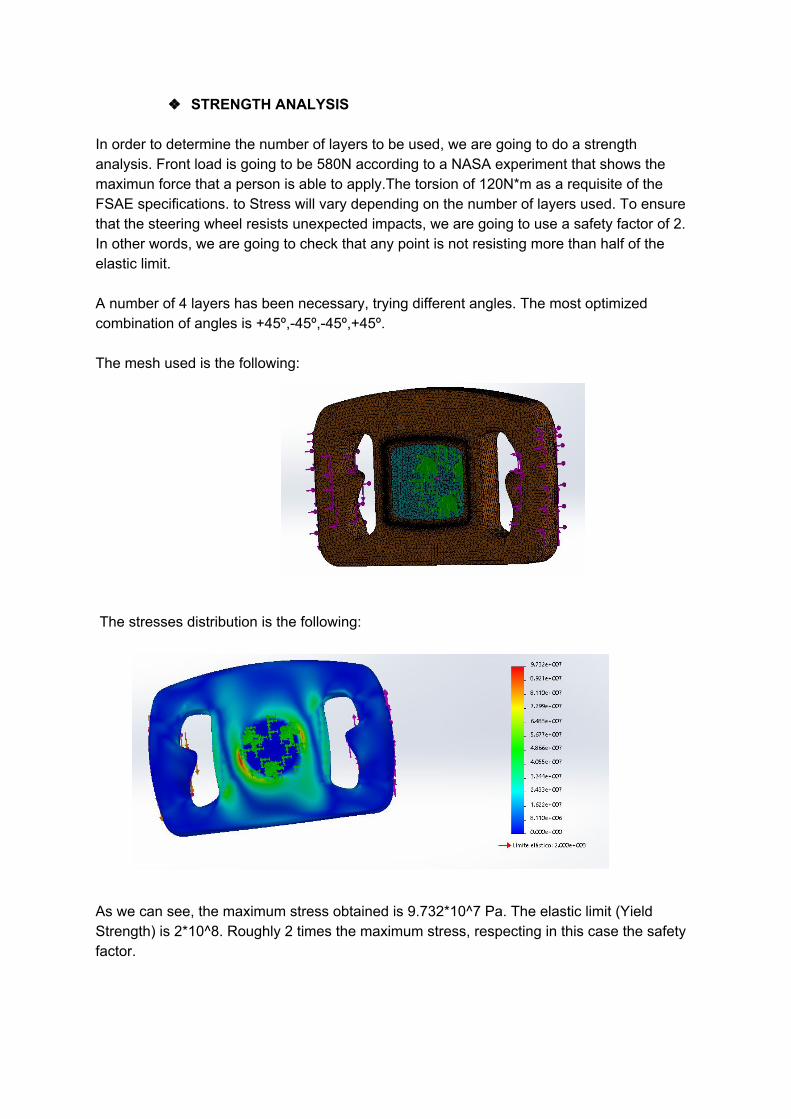
STRENGTH ANALYSIS In order to determine the number of layers to be used, we are going to do a strength analysis. Front load is going to be 580N according to a NASA experiment that shows the maximun force that a person is able to apply.The torsion of 120N*m as a requisite of the FSAE specifications. to Stress will vary depending on the number of layers used. To ensure that the steering wheel resists unexpected impacts, we are going to use a safety factor of 2. In other words, we are going to check that any point is not resisting more than half of the elastic limit. A number of 4 layers has been necessary, trying different angles. The most optimized combination of angles is +45º,45º,45º,+45º. The mesh used is the following: The stresses distribution is the following:
As we can see, the maximum stress obtained is 9.732*10^7 Pa. The elastic limit (Yield Strength) is 2*10^8. Roughly 2 times the maximum stress, respecting in this case the safety factor.

The maximum deformation is less than 1 mm. Assuming that this variation is acceptable, we can determine that all the requirements has been accomplished.
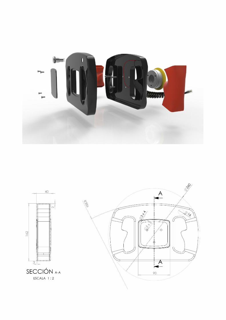
FINAL DESIGN After all the research, creating and testing, we finally were able to design a steering wheel that meets all our objectives. Achieving weight, ergonomics, and FSAE rules among others. These are the main specifications:
Hollowbody design Carbon Fiber composite material 350g (65% less than actual) 2mm thickness Ergonomic Upgradeable Accomplishes FSAE rules
Conclusions and considerations We can take several conclusions for this project. As engineers we have to know how to manage not only our time, but also people. We need a good methodology to adjust the deadlines, to meet the requirements and in conclusion, to succeed. While this may seem obvious, this project really highlighted this points. As the first project of this characteristics for all of us, we had to spend time deciding how to coordinate and manage all the work to be done. Our advisor, Dr. Youssef, helped a lot in this project. As students that we still are, we found ourselves stuck in several occasions. Luckily, the theory learned during the lectures and the meetings with Dr. Youssef made us able to accomplish the overall design of the project. To summarize, this project didn’t only help us to learn about designing and analyzing, but also to learn how to manage a project since the beginning. We have learned the importance of having reliable sources to find information, the necessity of research and the value of time. The passion for this project and the will of learning, were the key to succeed. All the members of the team worked a lot on different specific areas. Helping each other and doing extra efforts for the rest of the teammates has been also determinant. We would like to thank the “Aztec Racing Team” for letting us be part of this great experience, Dr.Youssef for showing us the right path to accomplish our goals and Dr.Kee Moon for giving us tools to solve our challenges.
References
2015 Formula SAE® Rules Links:
http://www.f1technical.net/forum/viewtopic.php?t=14061
https://www.youtube.com/watch?v=71rJ5OMOKTY
https://www.youtube.com/watch?v=rKAzE1pbf1M
Pneumatic DRS Testing - 14/1/2013 on Vimeo
http://www.monashmotorsport.com/wp-content/uploads/ANSYS-Iss114.p
df
http://www.f1technical.net/forum/viewtopic.php?f=14&t=22303

A Drag Reduction System developed for the Formula SAE
Manufacturing
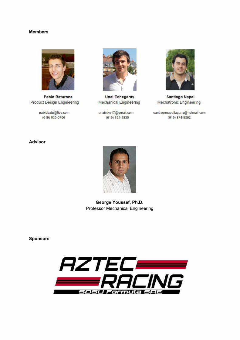
Members
Advisor
George Youssef, Ph.D. Professor Mechanical Engineering
Sponsors

MECHANICS
The main difficulty of the drs mechanics part was manufacturing a precise and lightweight structure and parts to accomplish the desired obtain ratios that where previously calculated and forecasted to end up with the optimum open position. We have gone through a different difficulties throughout the manufacturing which lead us to make small refinements for the manufacturing part.
About the structure, we went through a small problem in our manufacturing for the brackets. At first, we calculated the required parameters considering our material thickness and properties which result on: Bend Allowance 0.57” and Minimum Bend Radius 0.32”. Having our bracket process fully defined, we did our CAD drawings and export them to dfg format to cut them in the waterjet. After having our cutted part ready we started with the bending process. Assisted with help from the machine shop we realized that the bending machine was not able to produce our desired bending parameters due to the lack of a tool measure. As a result, bend Radius too small and bending separation too narrow forcing the fracture of the part.
Facing this early problem on the manufacturing, we did a quick redesign for welding so we could cut each brackets in 3 different pieces and weld them using the gap and avoiding the bending problems.
The cutting and tolerance involved on the assembly were successful which took as to the welding process. We used standard tungsten EDM electrodes to unify the three parts and after finishing that with sand the junctions to ensure the surface quality.
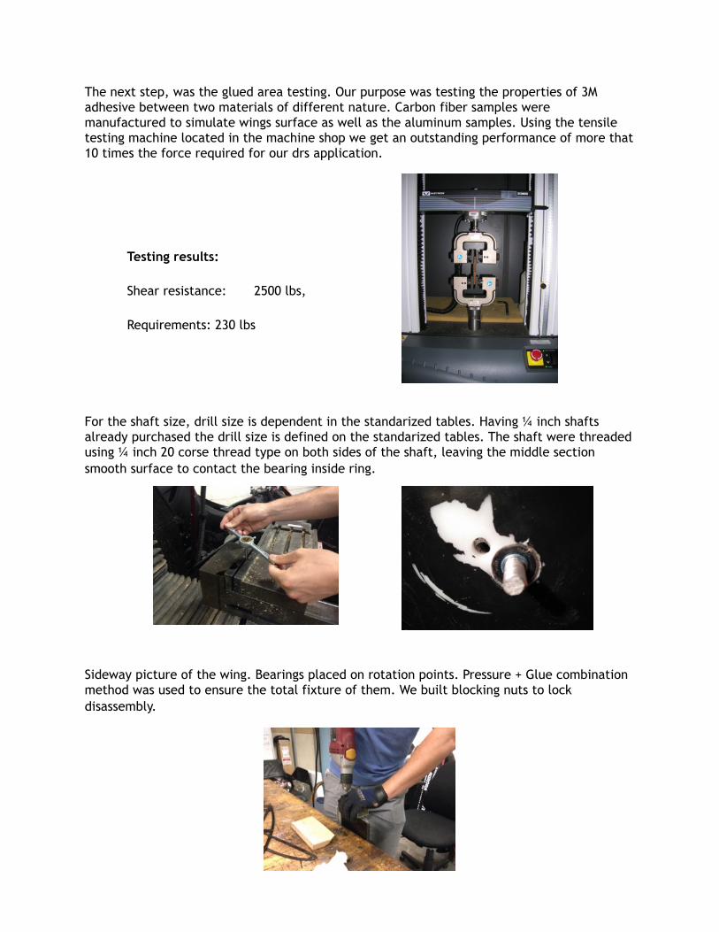
The next step, was the glued area testing. Our purpose was testing the properties of 3M adhesive between two materials of different nature. Carbon fiber samples were manufactured to simulate wings surface as well as the aluminum samples. Using the tensile testing machine located in the machine shop we get an outstanding performance of more that 10 times the force required for our drs application.
Testing results:
Shear resistance: 2500 lbs,
Requirements: 230 lbs
For the shaft size, drill size is dependent in the standarized tables. Having ¼ inch shafts already purchased the drill size is defined on the standarized tables. The shaft were threaded using ¼ inch 20 corse thread type on both sides of the shaft, leaving the middle section smooth surface to contact the bearing inside ring.
Sideway picture of the wing. Bearings placed on rotation points. Pressure + Glue combination method was used to ensure the total fixture of them. We built blocking nuts to lock disassembly.
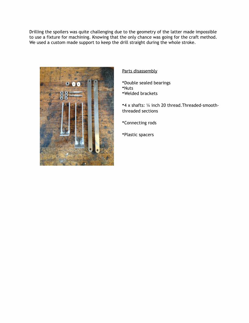
Drilling the spoilers was quite challenging due to the geometry of the latter made impossible
to use a fixture for machining. Knowing that the only chance was going for the craft method.
We used a custom made support to keep the drill straight during the whole stroke.
Parts disassembly
•Double sealed bearings
•Nuts
•Welded brackets
•4 x shafts: ¼ inch 20 thread.Threaded-smooth-
threaded sections
•Connecting rods
•Plastic spacers
ELECTRONICS
The goal of implementing an electronic system controlled by Arduino comes for several reasons. Firstly, the linear actuator has a DC motor inside that provides the power to create movement. We want to inverse the voltage when we want to change the position of the rear wing and only electric devices can’t accomplish that in a simple way. Besides, the system is also controlled by the brake, so we want to manage both inputs correctly with a program. And last but not least, the Arduino allows keeping improving the system. It could be made completely automatic with more inputs such as speed and turning sensors.
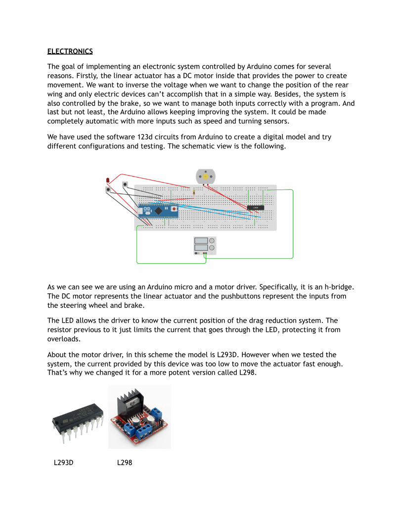
We have used the software 123d circuits from Arduino to create a digital model and try different configurations and testing. The schematic view is the following.
As we can see we are using an Arduino micro and a motor driver. Specifically, it is an h-bridge. The DC motor represents the linear actuator and the pushbuttons represent the inputs from the steering wheel and brake.
The LED allows the driver to know the current position of the drag reduction system. The resistor previous to it just limits the current that goes through the LED, protecting it from overloads.
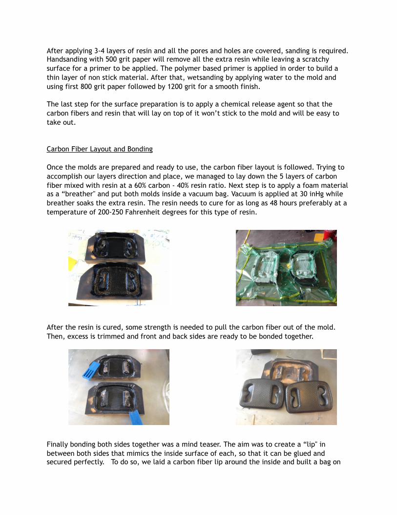
About the motor driver, in this scheme the model is L293D. However when we tested the system, the current provided by this device was too low to move the actuator fast enough. That’s why we changed it for a more potent version called L298.
L293D L298

The code for the Arduino is the following:

Testing Process
In order to save as much money as possible we started testing with a small DC motor, so we make sure the most expensive devices are protected until we make sure the system works.
Once we figured out that the program worked exactly as we wanted we went ahead and connect the linear actuator. A more powerful battery was necessary as well to provide enough current.
Finally, we put the breadboard into a waterproof project box and we change the wires for those which specifically fit the dimensions of the car. In order to make the steering wheel detachable we used professional contacts.
Besides, the pushbutton in the brakes used for testing was changed for a pressure switch. This makes the braking process more reliable to deactivate the system as soon as the driver brakes.

STEERING WHEEL
The steering wheel work for the manufacturing semester was challenging. Our main objective was to develop the process for efficiently fabricate the carbon fiber steering wheel accomplishing all of our design requirements, such as a 60% of weight reduction, increase the ergonomics and upgradeability. There were several steps to follow in order to end up with a well fabricated product.
During the winter break we were able to improve the design of the whole steering wheel. We refined the shape and managed to improve the Carbon Fibers layout in Solidworks to 5 layers (15, 75,0,75,15 degrees) achieving a safety factor of 2.68.
Mold Design and Manufacturing
The steering wheel requires a two-piece mold to be manufactured in order to achieve the hollow body we are aiming for. To do so, it is needed to design a CAD model of each mold and create different CNC machining toolpaths.
The first step is to generate the CAD files of the molds. They are based on cutting the Steering Wheel’s CAD in half with a specific “tangent cut” throughout the whole surface. This is done in order to have all the surfaces of each mold going from perpendicular to parallel in the direction of “pulling out”. Next we can see two pictures representing the mold’s surface. Red is the portion of the surface that needs to be cut considering the “tangent cut”.
Green: Front side mold; Grey: Back side mold; Red: Portion that needs specific cut

Once the CAD files are designed, the next step is to generate the CNC Machining Toolpaths. For this we used the integrated CAM software for Solidworks called HSM Works. This software allows you to generate different kinds of “passes" around the 3D file and apply parameters like speed of the tool spinning & moving, dimensions of the drill, material to be drilled, height of steps, etc. To give an example, a higher speed of the drill makes it easier and safer to remove material. But on the other hand, it can lead to overheat the material and start deforming, so there is always compromise between the speeds, time and material. For this design and the smooth surface we needed, we decided doing two passes, a rough one with a ½ inch standard tip drill and a second and slower for the finish with a rounded tip ¼ inch.
The material we used for the molds is a High Density Foam called RenShape 5045, with a density of 30 lbs/ft3. This type of Foam is widely used for machining molds for small scale objects due to its good mechanical properties and easiness to machine and prepare. The machining time for each mold was 3-4 hours.
Preparing the Mold’s Surface
Next step is to prepare the surface, covering all the pores of the material itself and little holes that the machining process left. For this, we used West Systems resin resources: Epoxy Resin (covering pores), Fast and Slow Hardeners (resin catalysers), Microspheres (Fine glass bubbles to cover holes and scratches), plastic cups and scrapers. The mixture ratio of the resin is 5 part resin to 1 part hardener. Microspheres are added to give consistency without increasing weight for the holes.
After applying 3-4 layers of resin and all the pores and holes are covered, sanding is required. Handsanding with 500 grit paper will remove all the extra resin while leaving a scratchy surface for a primer to be applied. The polymer based primer is applied in order to build a thin layer of non stick material. After that, wetsanding by applying water to the mold and using first 800 grit paper followed by 1200 grit for a smooth finish.
The last step for the surface preparation is to apply a chemical release agent so that the carbon fibers and resin that will lay on top of it won’t stick to the mold and will be easy to take out.
Carbon Fiber Layout and Bonding
Once the molds are prepared and ready to use, the carbon fiber layout is followed. Trying to accomplish our layers direction and place, we managed to lay down the 5 layers of carbon fiber mixed with resin at a 60% carbon - 40% resin ratio. Next step is to apply a foam material as a “breather" and put both molds inside a vacuum bag. Vacuum is applied at 30 inHg while breather soaks the extra resin. The resin needs to cure for as long as 48 hours preferably at a temperature of 200-250 Fahrenheit degrees for this type of resin.
After the resin is cured, some strength is needed to pull the carbon fiber out of the mold. Then, excess is trimmed and front and back sides are ready to be bonded together.
Finally bonding both sides together was a mind teaser. The aim was to create a “lip" in between both sides that mimics the inside surface of each, so that it can be glued and secured perfectly. To do so, we laid a carbon fiber lip around the inside and built a bag on
the inside too. Then we put the second half of the steering wheel on top and applied vacuum
in between the bag and the whole carbon fiber steering wheel so that the bag expands and
pushes the lip against the two.
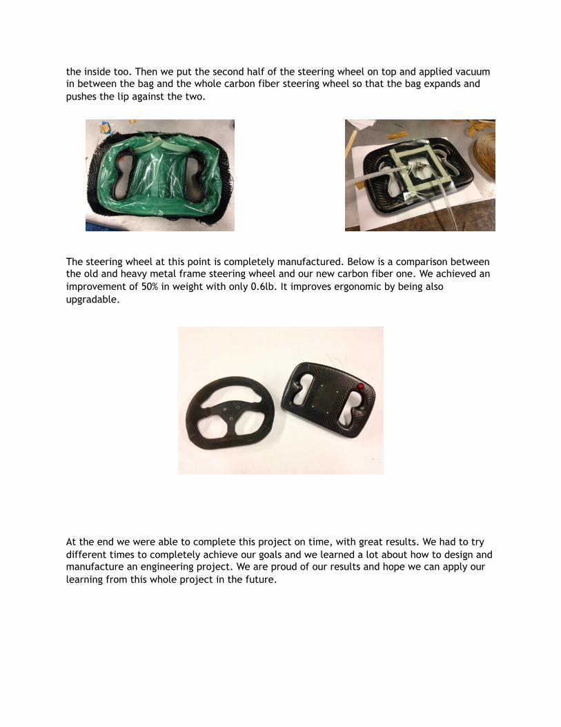
The steering wheel at this point is completely manufactured. Below is a comparison between
the old and heavy metal frame steering wheel and our new carbon fiber one. We achieved an
improvement of 50% in weight with only 0.6lb. It improves ergonomic by being also
upgradable.
At the end we were able to complete this project on time, with great results. We had to try
different times to completely achieve our goals and we learned a lot about how to design and
manufacture an engineering project. We are proud of our results and hope we can apply our
learning from this whole project in the future.