
Draft No 2 CEN - Unict · Partie 4 : Silos, réservoirs et réseaux de tuyauteries Teil 4 : Silos,...
83
Draft 2(Stage 32) Page 1 Draft December 2003June 2002 prEN 1998-4:200X EUROPEAN STANDARD prEN 1998-4 : 2003 NORME EUROPÉENNE EUROPÄISCHE NORM December 2003 UDC Descriptors: Doc CEN/TC250/SC8/N387 English version Eurocode 8 : Design of structures for earthquake resistance Part 4: Silos, tanks and pipelines Calcul des structures pour leur résistance aux séismes Auslegung von Bauwerken gegen Erdbeben Partie 4 : Silos, réservoirs et réseaux de tuyauteries Teil 4 : Silos, Tankbauwerke und Rohrleitungen Draft No 2 CEN European Committee for Standardisation Comité Européen de Normalisation Europäisches Komitee für Normung Central Secretariat: rue de Stassart 36, B-1050 Brussels © 2003 Copyright reserved to all CEN members Ref. No. EN 1998-4 : 2003 (E) EUROPEAN PRESTANDARD prEN 1998-4
Transcript of Draft No 2 CEN - Unict · Partie 4 : Silos, réservoirs et réseaux de tuyauteries Teil 4 : Silos,...

Draft 2(Stage 32) Page 1Draft December 2003June 2002 prEN 1998-4:200X
EUROPEAN STANDARD prEN 1998-4 : 2003NORME EUROPÉENNEEUROPÄISCHE NORM December 2003
UDCDescriptors:
Doc CEN/TC250/SC8/N387English version
Eurocode 8 : Design of structures for earthquake resistance
Part 4: Silos, tanks and pipelines
Calcul des structures pour leur résistanceaux séismes
Auslegung von Bauwerken gegenErdbeben
Partie 4 : Silos, réservoirs et réseaux detuyauteries
Teil 4 : Silos, Tankbauwerke undRohrleitungen
Draft No 2
CENEuropean Committee for Standardisation
Comité Européen de NormalisationEuropäisches Komitee für Normung
Central Secretariat: rue de Stassart 36, B-1050 Brussels
© 2003 Copyright reserved to all CEN members Ref. No. EN 1998-4 : 2003 (E)
EUROPEAN PRESTANDARD prEN 1998-4

Draft 2(Stage 32) Page 2Draft December 2003June 2002 prEN 1998-4:200X
PRÉNORME EUROPÉENNEEUROPÄISCHE VORNORM
Doc CEN/TC250/SC8/N322
English version
Eurocode 8: Design of structures for earthquake resistance
Part 4: Silos, tanks and pipelines
DRAFT No 1(Stage 32)June 2002
CEN
European Committee for StandardizationComité Européen de NormalisationEuropäisches Komitee für Normung
Central Secretariat: rue de Stassart 36, B1050 Brussels

Draft 2(Stage 32) Page 3Draft December 2003June 2002 prEN 1998-4:200X
CEN 2002 Copyright reserved to all CEN members
Ref.No ENV 1998-4
Draft 2(Stage 32) Page 4Draft December 2003June 2002 prEN 1998-4:200X
Contents1 GENERAL.........................................................................................................................................1
1.1 SCOPE .............................................................................................................................................11.2 NORMATIVE REFERENCES .............................................................................................................11
1.2.1 General reference standards ................................................................................................21.3 ASSUMPTIONS.................................................................................................................................21.4 DISTINCTION BETWEEN PRINCIPLES AND APPLICATIONS RULES ......................................................21.5 TERMS AND DEFINITIONS................................................................................................................2
1.5.1 Terms common to all Eurocodes ..........................................................................................21.5.2 Additional terms used in the present standard .....................................................................2
1.6 SYMBOLS ........................................................................................................................................21.7 S.I. UNITS .....................................................................................................................................22
2 GENERAL RULES ........................................................................................................................33
2.1 SAFETY REQUIREMENTS................................................................................................................332.1.1 General ...............................................................................................................................332.1.2 Damage limitation state......................................................................................................332.1.3 Ultimate limit state .............................................................................................................332.1.4 Reliability differentiation....................................................................................................442.1.5 System versus element reliability........................................................................................552.1.6 Conceptual design ..............................................................................................................55
2.2 SEISMIC ACTION............................................................................................................................662.3 ANALYSIS .....................................................................................................................................77
2.3.1 Methods of analysis ............................................................................................................772.3.2 Behaviour factors ...............................................................................................................882.3.3 Damping .............................................................................................................................88
2.3.3.1 Structural damping ....................................................................................................................... 882.3.3.2 Contents damping......................................................................................................................... 882.3.3.3 Foundation damping..................................................................................................................... 99
2.3.4 Interaction with the soil ......................................................................................................992.3.5 Weighted damping ..............................................................................................................99
2.4 SAFETY VERIFICATIONS ................................................................................................................992.4.1 General ...............................................................................................................................992.4.2 Combinations of seismic action with other actions ............................................................99
3 SPECIFIC RULES FOR SILOS ...............................................................................................1111
3.1 PROPERTIES OF STORED SOLIDS AND DYNAMIC PRESSURES.......................................................11113.2 COMBINATION OF GROUND MOTION COMPONENTS ...................................................................11113.3 ANALYSIS .................................................................................................................................11113.4 BEHAVIOUR FACTORS ...............................................................................................................13133.5 VERIFICATIONS.........................................................................................................................1414
3.5.1 Damage limitation state..................................................................................................14143.5.2 Ultimate limit state .........................................................................................................1414
3.5.2.1 Global stability ......................................................................................................................... 14143.5.2.2 Shell ......................................................................................................................................... 15153.5.2.3 Anchors .................................................................................................................................... 15153.5.2.4 Foundations .............................................................................................................................. 1515
4 SPECIFIC RULES FOR TANKS .............................................................................................1616
4.1 COMPLIANCE CRITERIA.............................................................................................................16164.1.1 General ...........................................................................................................................16164.1.2 Damage limitation state..................................................................................................16164.1.3 Ultimate limit state .........................................................................................................1616
4.2 COMBINATION OF GROUND MOTION COMPONENTS ...................................................................17174.3 METHODS OF ANALYSIS ............................................................................................................1717
4.3.1 General ...........................................................................................................................17174.3.2 Behaviour factors ...........................................................................................................17174.3.3 Hydrodynamic effects .....................................................................................................1818
4.4 VERIFICATIONS.........................................................................................................................1818

Draft 2(Stage 32) Page 5Draft December 2003June 2002 prEN 1998-4:200X
4.4.1 Damage limitation state..................................................................................................18184.4.1.1 Shell ......................................................................................................................................... 18184.4.1.2 Piping ....................................................................................................................................... 1919
4.4.2 Ultimate limit state .........................................................................................................19194.4.2.1 Stability .................................................................................................................................... 19194.4.2.2 Shell ......................................................................................................................................... 19194.4.2.3 Piping ....................................................................................................................................... 19194.4.2.4 Anchorages............................................................................................................................... 19194.4.2.5 Foundations .............................................................................................................................. 2020
4.5 COMPLEMENTARY MEASURES...................................................................................................20204.5.1 Bunding ..........................................................................................................................20204.5.2 Sloshing ..........................................................................................................................20204.5.3 Piping interaction ...........................................................................................................2020
5 SPECIFIC RULES FOR ABOVE-GROUND PIPELINES ....................................................2121
5.1 GENERAL ..................................................................................................................................21215.2 SAFETY REQUIREMENTS............................................................................................................2121
5.2.1 Damage limitation state..................................................................................................21215.2.2 Ultimate limit state .........................................................................................................22225.2.3 Reliability differentiation................................................................................................2222
5.3 SEISMIC ACTION........................................................................................................................22225.3.1 General ...........................................................................................................................22225.3.2 Earthquake vibrations ....................................................................................................23235.3.3 Differential movement ....................................................................................................2323
5.4 METHODS OF ANALYSIS ............................................................................................................23235.4.1 Modelling........................................................................................................................23235.4.2 Analysis ..........................................................................................................................23235.4.3 Behaviour factors ...........................................................................................................2424
5.5 VERIFICATIONS.........................................................................................................................2424
6 SPECIFIC RULES FOR BURIED PIPELINES......................................................................2626
6.1 GENERAL ..................................................................................................................................26266.2 SAFETY REQUIREMENTS............................................................................................................2626
6.2.1 Damage limitation state..................................................................................................26266.2.2 Ultimate limit state .........................................................................................................26266.2.3 Reliability differentiation................................................................................................2727
6.3 SEISMIC ACTION........................................................................................................................27276.3.1 General ...........................................................................................................................27276.3.2 Earthquake vibrations ....................................................................................................28286.3.3 Modelling of seismic waves ............................................................................................28286.3.4 Permanent soil movements .............................................................................................2828
6.4 METHODS OF ANALYSIS (WAVE PASSAGE) ................................................................................28286.5 VERIFICATIONS.........................................................................................................................2828
6.5.1 General ...........................................................................................................................28286.5.1.1 Buried pipelines on stable soil.................................................................................................. 29296.5.1.2 Buried pipelines under differential ground movements (welded steel pipes) ( ......................... 2929
6.6 DESIGN MEASURES FOR FAULT CROSSINGS ...............................................................................2929
ANNEX A (INFORMATIVE) SEISMIC ANALYSIS OF SILOS ...................................................3131
ANNEX B (INFORMATIVE) SEISMIC ANALYSIS PROCEDURES FOR TANKS ..................3737
ANNEX C (INFORMATIVE) BURIED PIPELINES.......................................................................6767

Draft 2(Stage 32) Page 6Draft December 2003June 2002 prEN 1998-4:200X
Foreword
This document (EN 1998-4:200X) has been prepared by Technical Committee CEN/TC250 "Structural Eurocodes", the secretariat of which is held by BSI.
This European Standard shall be given the status of a national standard, either bypublication of an identical text or by endorsement, at the latest by MM-200Y, andconflicting national standards shall be withdrawn at the latest by MM-20YY.
This document supersedes ENV 1998-4:1997.
CEN/TC 250 is responsible for all Structural Eurocodes.
Background of the Eurocode programme
In 1975, the Commission of the European Community decided on an action programmein the field of construction, based on article 95 of the Treaty. The objective of theprogramme was the elimination of technical obstacles to trade and the harmonisation oftechnical specifications.
Within this action programme, the Commission took the initiative to establish a set ofharmonised technical rules for the design of construction works which, in a first stage,would serve as an alternative to the national rules in force in the Member States and,ultimately, would replace them.
For fifteen years, the Commission, with the help of a Steering Committee withRepresentatives of Member States, conducted the development of the Eurocodesprogramme, which led to the first generation of European codes in the 1980’s.
In 1989, the Commission and the Member States of the EU and EFTA decided, on thebasis of an agreement1 between the Commission and CEN, to transfer the preparationand the publication of the Eurocodes to CEN through a series of Mandates, in order toprovide them with a future status of European Standard (EN). This links de facto theEurocodes with the provisions of all the Council’s Directives and/or Commission’sDecisions dealing with European standards (e.g. the Council Directive 89/106/EEC onconstruction products - CPD - and Council Directives 93/37/EEC, 92/50/EEC and89/440/EEC on public works and services and equivalent EFTA Directives initiated inpursuit of setting up the internal market).
The Structural Eurocode programme comprises the following standards generallyconsisting of a number of Parts:EN 1990 Eurocode: Basis of structural designEN 1991 Eurocode 1: Actions on structuresEN 1992 Eurocode 2: Design of concrete structures
1 Agreement between the Commission of the European Communities and the European Committee for
Standardisation (CEN) concerning the work on EUROCODES for the design of building and civilengineering works (BC/CEN/03/89).
Draft 2(Stage 32) Page 7Draft December 2003June 2002 prEN 1998-4:200X
EN 1993 Eurocode 3: Design of steel structuresEN 1994 Eurocode 4: Design of composite steel and concrete structuresEN 1995 Eurocode 5: Design of timber structuresEN 1996 Eurocode 6: Design of masonry structuresEN 1997 Eurocode 7: Geotechnical designEN 1998 Eurocode 8: Design of structures for earthquake resistanceEN 1999 Eurocode 9: Design of aluminium structures
Eurocode standards recognise the responsibility of regulatory authorities in eachMember State and have safeguarded their right to determine values related to regulatorysafety matters at national level where these continue to vary from State to State.
Status and field of application of Eurocodes
The Member States of the EU and EFTA recognise that Eurocodes serve as referencedocuments for the following purposes:– as a means to prove compliance of building and civil engineering works with the
essential requirements of Council Directive 89/106/EEC, particularly EssentialRequirement N°1 - Mechanical resistance and stability - and Essential RequirementN°2 - Safety in case of fire;
– as a basis for specifying contracts for construction works and related engineeringservices;
– as a framework for drawing up harmonised technical specifications for constructionproducts (ENs and ETAs)
The Eurocodes, as far as they concern the construction works themselves, have a directrelationship with the Interpretative Documents2 referred to in Article 12 of the CPD,although they are of a different nature from harmonised product standards3. Therefore,technical aspects arising from the Eurocodes work need to be adequately considered byCEN Technical Committees and/or EOTA Working Groups working on product
2 According to Art. 3.3 of the CPD, the essential requirements (ERs) shall be given concrete formin interpretative documents for the creation of the necessary links between the essential requirements andthe mandates for hENs and ETAGs/ETAs.
3 According to Art. 12 of the CPD the interpretative documents shall :
a) give concrete form to the essential requirements by harmonising the terminology and thetechnical bases and indicating classes or levels for each requirement where necessary ;
b) indicate methods of correlating these classes or levels of requirement with the technicalspecifications, e.g. methods of calculation and of proof, technical rules for project design, etc. ;
c) serve as a reference for the establishment of harmonised standards and guidelines for Europeantechnical approvals.
The Eurocodes, de facto, play a similar role in the field of the ER 1 and a part of ER 2.

Draft 2(Stage 32) Page 8Draft December 2003June 2002 prEN 1998-4:200X
standards with a view to achieving a full compatibility of these technical specificationswith the Eurocodes.
The Eurocode standards provide common structural design rules for everyday use forthe design of whole structures and component products of both a traditional and aninnovative nature. Unusual forms of construction or design conditions are notspecifically covered and additional expert consideration will be required by the designerin such cases.
National Standards implementing Eurocodes
The National Standards implementing Eurocodes will comprise the full text of theEurocode (including any annexes), as published by CEN, which may be preceded by aNational title page and National foreword, and may be followed by a National annex(informative).
The National annex may only contain information on those parameters which are leftopen in the Eurocode for national choice, known as Nationally Determined Parameters,to be used for the design of buildings and civil engineering works to be constructed inthe country concerned, i.e. :
– values and/or classes where alternatives are given in the Eurocode,
– values to be used where a symbol only is given in the Eurocode,
– country specific data (geographical, climatic, etc.), e.g. snow map,
– the procedure to be used where alternative procedures are given in the Eurocode.
It may also contain
– decisions on the application of informative annexes,
– references to non-contradictory complementary information to assist the user toapply the Eurocode.
Links between Eurocodes and harmonised technical specifications (ENs and ETAs)for products
There is a need for consistency between the harmonised technical specifications forconstruction products and the technical rules for works4. Furthermore, all theinformation accompanying the CE Marking of the construction products which refer toEurocodes shall clearly mention which Nationally Determined Parameters have beentaken into account.
Additional information specific to EN 1998-4
4 See Art.3.3 and Art.12 of the CPD, as well as clauses 4.2, 4.3.1, 4.3.2 and 5.2 of ID 1.

Draft 2(Stage 32) Page 9Draft December 2003June 2002 prEN 1998-4:200X
The scope of EN 1998 is defined in 1.1.1 of EN 1998-1:2004. The scope of this Part ofEN 1998 is defined in 1.1. Additional Parts of Eurocode 8 are listed in EN 1998-1:2004,1.1.3.
EN 1998-4:200X is intended for use by:
– clients (e.g. for the formulation of their specific requirements on reliability levelsand durability) ;
– designers and constructors ;
– relevant authorities.
For the design of structures in seismic regions the provisions of this European Standardare to be applied in addition to the provisions of the other relevant parts of Eurocode 8and the other relevant Eurocodes. In particular, the provisions of this European Standardcomplement those of EN 1991-4, EN 1992-3, EN 1993-4-1, EN 1993-4-2 and EN 1993-4-3, which do not cover the special requirements of seismic design.
National annex for EN 1998-4
This standard gives alternative procedures, values and recommendations for classeswith notes indicating where national choices may be made. Therefore the NationalStandard implementing EN 1998-4 should have a National Annex containing allNationally Determined Parameters to be used for the design of buildings and civilengineering works to be constructed in the relevant country.
National choice is allowed in EN 1998-4:200X through clauses:
Reference Item
Draft 2(Stage 32) Page 1Draft December 2003June 2002 prEN 1998-4:200X
1 GENERAL
1.1 Scope
(1)P This standard aims at providing principles and application rules for the seismic designof the structural aspects of facilities composed of above-ground and buried pipeline systemsand of storage tanks of different types and uses, as well as for independent items, such as forexample single water towers serving a specific purpose or groups of silos enclosing granularmaterials, etc. This standard may also be used as a basis for evaluating the resistance ofexisting facilities and to assess any required strengthening.
(2) P This standard includes the additional criteria and rules required for the seismic designof these structures without restrictions on their size, structural types and other functionalcharacteristics. For some types of tanks and silos, however, it also provides detailed methodsof assessment and verification rules.
(3) P This standard may not be complete for those facilities associated with large risks to thepopulation or the environment, for which additional requirements shall be established by thecompetent authorities. This standard is also not complete for those construction works whichhave uncommon structural elements and which require special measures to be taken andspecial studies to be performed to ensure earthquake protection. In those two cases the presentstandard gives general principles but not detailed application rules.
(4) The nature of lifeline systems which often characterises the facilities covered by thisstandard requires concepts, models and methods that may differ substantially from those incurrent use for more common structural types. Furthermore, the response and the stability ofsilos and tanks subjected to strong seismic actions may involve rather complex interactionphenomena between of soil-structure and stored material (either -fluid or granular)interaction,not easily amenable to simplified design procedures. Equally challenging may prove to be thedesign of a pipeline system through areas with poor and possibly unstable soils. For thereasons given above, the organisation of this standard is to some extent different from that ofcompanion Parts of EN 1998. This standard is, in general, restricted to basic principles andmethodological approaches.
NOTE Detailed analysis procedures going beyond basic principles and methodological approaches aregiven in Annexes A, B and C for a number of typical situations.
(5) P For the formulation of the general requirements as well as for their its implementation,a distinction can shall be made between independent structures and redundant systems, via thechoice of importance factors and/or through the definition of adapted specific verificationcriteria.
(6) P A structure maycan be considered as independent when its structural and functionalbehaviour during and after a seismic event is not influenced by that of other structures, and ifthe consequences of its failure relate only to the functions demanded from it.
Draft 2(Stage 32) Page 2Draft December 2003June 2002 prEN 1998-4:200X
1.2 Normative references
(1)P This European Standard incorporates by dated or undated reference, provisionsfrom other publications. These normative references are cited at the appropriate places in thetext and the publications are listed hereafter. For dated references, subsequent amendments toor revisions of any of these publications apply to this European Standard only whenincorporated in it by amendment or revision. For undated references the latest edition of thepublication referred to applies (including amendments).
1.2.1 General reference standards
EN 1990 : 2002 Eurocode - Basis of structural design
EN 1998-1 : 2004 Eurocode 8 - Design of structures for earthquake resistance – Part 1:General rules, seismic actions and rules for buildings
EN 1998-5 : 2004 Eurocode 8 - Design of structures for earthquake resistance – Part 5:Foundations, retaining structures and geotechnical aspects
EN 1998-6 : 200X Eurocode 8 - Design of structures for earthquake resistance – Part 6:Towers, masts and chimneys
1.3 Assumptions
(1)P The general assumptions of EN 1990:2002, 1.3 apply.
1.4 Distinction between principles and applications rules
(1)P The rules of EN 1990:2002, 1.4 apply.
1.5 Terms and dDefinitions
1.5.1 Terms common to all Eurocodes
(1)P The terms and definitions given in EN 1990:2002, 1.5 apply.
(2)P EN 1998-1: 200X2004, 1.5.1 applies for terms common to all Eurocodes.
1.5.2 Additional terms used in the present standard
(1) For the purposes of this standard the terms defined in EN 1998-1:2004, 1.5.2 apply.
1.6 Symbols
(1) For the purposes of this European Standard the following symbols apply. All symbolsused in Part 4 are defined in the text when they first occur, for ease of use. In addition, a listof the symbols is given below. Some symbols occurring only in the annexes are definedtherein:

Draft 2(Stage 32) Page 3Draft December 2003June 2002 prEN 1998-4:200X
NOTE: The list of symbols shall be added later on
1.7 S.I. Units
(1)P S.I. Units shall be used in accordance with ISO 1000.
(2) In addition the units recommended in EN 1998-1:2004, 1.7 apply.

Draft 2(Stage 32) Page 4Draft December 2003June 2002 prEN 1998-4:200X
1.22 GENERAL RULESSAFETY REQUIREMENTS
2.1 Safety requirements
1.2.12.1.1 General
(1) P This standard deals with structures which may differ widely in such basic features as:
– the nature and amount of stored product and associated potential danger
– the functional requirements during and after the seismic event
– the environmental conditions.
(2) Depending on the specific combination of the indicated features, differentformulations of the general requirements are appropriate. For the sake of consistency with thegeneral framework of the Eurocodes, the two-limit-states format is retained, with a suitablyadjusted definition.
1.2.22.1.2 Damage limitation limit state
(1) P Depending on the characteristics and the purposes of the structures considered one orboth of the two following damage limitation states may need to be satisfied:
– full integrity;
– minimum operating level.
(2) P In order to satisfy tThe "full integrity" requirement, implies that the consideredsystem, including a specified set of accessory elements integrated with it, shall remains fullyserviceable and leak proof under a seismic event having an annual probability of exceedancewhose value is to be established based on the consequences of its loss of function and/or ofthe leakage of the content.
(3) P Satisfaction of theThe "minimum operating level" requirement, means that impliesthat the considered system may suffer a certain amount of damage to some of its components,to an extent, however, that after the damage control operations have been carried out, thecapacity of the system can be restored up to a predefined level of operation. The seismic eventfor which this limit state may not be exceeded shall have an annual probability of exceedancewhose value is to be established based on the losses related to the reduced capacity of thesystem and to the necessary repairs.
PT NOTE: A more clear definition of the seismic events for the verification of these twodamage limitation states has to be provided. It may become a NDP
1.2.32.1.3 Ultimate limit state
(1)P The ultimate limit state of a system which shall be checked is defined as thatcorresponding to the loss of operational capacity of the system, with the possibility of partial
Draft 2(Stage 32) Page 5Draft December 2003June 2002 prEN 1998-4:200X
recovery (in the measure defined by the responsible authority) conditional to an acceptableamount of repairs. the limit state that guarantees the non collapse of the facility and theavoidance of uncontrolled loss of stored products.
(2)P For particular elements of the network, as well as for independent structures whosecomplete collapse would entail high risks, the ultimate limit state is defined as that of a stateof damage that, although possibly severe, would exclude brittle failures and would allow for acontrolled release of the contents. When the failure of the aforementioned elements does notinvolve appreciable risks to life and property, the ultimate limit state can be defined ascorresponding to total collapse.
(3)P The design seismic action for which the ultimate limit state must not be exceeded shallbe established based on the direct and indirect costs caused by the collapse of the system
1.2.42.1.4 Reliability differentiation
(1) P Pipeline networks and independent structures, either tanks or silos, shall be providedwith a level of protection proportioned to the number of people at risk and to the economicand environmental losses associated with their performance level being not achieved.
(2) P Reliability differentiation shall be achieved by appropriately adjusting the value of theannual probability of exceedance of the design seismic action.
(3) This adjustment should be implemented by classifying structures into differentimportance classes and applying to the reference seismic action an importance factor γI, asdefined in EN 1998-1:2004X, 2.1(3)P, the value of which depends on the importance class.Specific values of the factor γI, necessary to modify the action so as to correspond to a seismicevent of selected return period, depend on the seismicity of each region. The value of theimportance factor γI = 1,0 is associated with a seismic event having the reference return periodindicated in EN 1998-1:200X, 3.2.1(3).
NOTE For the dependence of the value of γI see Note to EN1998-1:2004X, 2.1(4)
(4)P For the structures within the scope of this standard it is appropriate to consider threedifferent Importance Classes, depending on the potential exposure to loss of life due to thefailure of the particular structure and on the environmental, economic and socialconsequences of failure. Further classification may be made within each Importance Class,depending on the use and contents of the facility and the ramifications implications for publicsafety.
NOTE Importance classes I, II and III correspond roughly to consequences classes CC13, CC2 andCC31, respectively, defined in EN 1990:2002, Annex B.
(5)P Class III refers to situations with a high risk to life and large environmental, economicand social consequences.
(6)P Situations with medium risk to life and considerable environmental, economic orsocial consequences belong to Class II.
(7)P Class III refers to situations where the risk to life is low and the environmental,economic and social consequences of failure are small or negligible.

Draft 2(Stage 32) Page 6Draft December 2003June 2002 prEN 1998-4:200X
(8) A more detailed definition of the classes, specific for pipeline systems, is given in4.2.1
NOTE The values to be ascribed to γI for use in a country may be found in its National Annex. Thevalues of γI may be different for the various seismic zones of the country, depending on the seismichazard conditions (see Note to EN 1998-1: 2004X, 2.1(4)) and on the public safety considerationsdetailed in 1.2.2.1.4. The recommended values of γI are given in Table 1.1N. In the column at left thereis a classification of the more common uses of these structures, while the three columns at right containthe recommended levels of protection in terms of the values of the importance factor γI for threeImportance Classes.
Table 21.1N Importance factors
Use of the structure/facility Importance ClassI II III3
Potable water supplyNon-toxic, non inflammable material
0,81,2 1,0 0,81,2
Fire fighting waterNon-volatile toxic materialLow flammability petrochemicals
1,0 1,4 1,2 1,01,4
Volatile toxic chemicalsExplosive and other high flammability liquids
1,21,6 1,4 1,21,6
1.2.52.1.5 System versus element reliability
(1) P The reliability requirements set forth in 1.2.2 and 1.2.3 refer to the whole systemunder consideration, be it constituted by a single component or by a set of componentsvariously connected to perform the functions required from it.
(2) Although a formal approach to system reliability analysis is outside the scope of thisstandard, the designer shall give explicit consideration to the role played by the variouselements in ensuring the continued operation of the system, especially when it is notredundant. In the case of very complex systems the design shall should be based on sensitivityanalyses.
(3)P Elements of the network, or of a structure in the network, which are shown to becritical, with respect to the failure of the system, shall be provided with an additional marginof protection, commensurate with the consequences of the failure. When there is no previousexperience, those critical elements should be experimentally investigated to verify theacceptability of the design assumptions.
(4) If more rigorous analyses are not undertaken, the additional margin of protection forcritical elements can be achieved by assigning these elements to a class of reliability(expressed in terms of Importance Class) one level higher than that proper to the system as awhole.
1.2.62.1.6 Conceptual design
(1) P Even when the overall seismic response is specified to be elastic (corresponding to avalue q = 1,5 for the behaviour factor), structural elements shall be designed and detailed forlocal ductility and constructed from ductile materials.
Draft 2(Stage 32) Page 7Draft December 2003June 2002 prEN 1998-4:200X
(2) P The design of a network or of an independent structure shall take into considerationthe following general aspects for mitigation of earthquake effects:
– Redundancy of the systems
– Absence of interaction of the mechanical and electrical components with the structuralelements.
– Easy access for inspection, maintenance and repair of damages;
– Quality control of the components;
(3) In order to avoid spreading of damage in redundant systems due to structuralinterconnection of components, the necessary appropriate parts should be isolated.
(4) In case of important facilities vulnerable to earthquakes, of which damage recovery isdifficult or time consuming, replacement parts or subassemblies should be provided.
1.32.2 Seismic action
(1) P The seismic action to be used in the determination of the seismic action effects for thedesign of silos, tanks and pipelines shall be that defined in EN 1998-1: 2004X, 3.2 in thevarious equivalent forms of elastic, site-dependent response spectra (EN 1998-1: 2004X,3.2.2), and time-history representation (EN 1998-1: 200X, 3.2.3.1). In those cases where abehaviour factor q larger than the value of 1,5 (considered as resultingderived fromoverstrength alone) is acceptable (see 1.102.34.2), the design spectrum for elastic analysisshall be used (EN 1998-1: 200X2004, 3.2.2.5). Additional provisions for the spatial variationof ground motion for buried pipelines are given in Section 5.
(2) P The two seismic actions to be used for checking the damage limitation state and theultimate limit state, respectively, shall be established by the competent National Authority onthe basis of the seismicity of the different seismic zones and of the level of the importanceImportance category Class of the specific facility.
(3) A reduction factor ν applied to the design seismic action, to take into account thelower return period of the seismic event associated with the damage limitation state may beconsidered as mentioned in EN 1998-1: 2004X, 2.1(1)P. The value of the reduction factor νmay also depend on the Importance Class of the structure. Implicit in its use is the assumptionthat the elastic response spectrum of the seismic action under which the “damage limitationrequirement” should be met has the same shape as the elastic response spectrum of the designseismic action corresponding to the “ ultimate limit state requirement” according to EN 1998-1: 2004,X (2.1(1)P and 3.2.1(3)) (See EN 1998-1: 2004,X (3.2.2.1(2)). In the absence of moreprecise information, the reduction factor ν applied on the design seismic actionwith the valueaccording to EN 1998-1: 2004,X (4.4.3.2(2)) may be used to obtain the seismic action for theverification of the damage limitation requirement.
NOTE The values to be ascribed to ν for use in a country may be found in its National Annex. Differentvalues of ν may be defined for the various seismic zones of a country, depending on the seismic hazardconditions and on the protection of property objective. The recommended values of ν are 0,54 forimportance classes I and II and ν = 0,45 for importance classes II and III.

Draft 2(Stage 32) Page 8Draft December 2003June 2002 prEN 1998-4:200X
1.42.3 Analysis
1.4.12.3.1 Methods of AnalysisMethods of analysis
(1) P For the structures within the scope of this standard the seismic actions effects shall ingeneral be determined on the basis of linear behaviour of the structures and of the soil in theirvicinity.
(2) P Nonlinear methods of analyses analysis may be used to obtain the seismic actioneffects for those special cases where consideration of nonlinear behaviour of the structure orof the surrounding soil is dictated by the nature of the problem, or where the elastic solutionwould be economically unfeasible. In those cases it shall be proved that the design obtainedpossesses at least the same amount of reliability as the structures explicitly covered by thisstandard.
(3)P Analysis for the evaluation of the effects of the seismic action relevant to the damagelimitation state shall be linear elastic, using the elastic spectra defined in EN 1998-1: 20040X,3.2.2.2 and EN 1998-1: 20040X, 3.2.2.3, multiplied by the reduction factor ν of referred to in1.92.23(3) and entered with a weighted average value of the viscous damping that takes intoaccount the different damping values of the different materials/elements according to1.102.34.5 and to EN 1998-1: 20040X, 3.2.2.2(3).
(4)P Analysis for the evaluation of the effects of the seismic action relevant to the ultimatelimit state may be elastic, using the design spectra which are specified in EN 1998-1: 20040X,3.2.2.5 for a damping ratio of 5% and make use of the behaviour factor q to account for thecapacity of the structure to dissipate energy, through mainly ductile behaviour of its elementsand/or other mechanisms, as well as the influence of viscous damping different from 5%.
(5)P Unless otherwise specified for particular types of structures in the relevant parts of thisstandard, the types of analysis that may be applied are those indicated in EN 1998-1: 2000X4,4.3.3, namely:
a) the “lateral force method” of (linear-elastic) analysis (see EN 1998-1: 20040X 4.3.3.2);
b) the “modal response spectrum” (linear-elastic) analysis (see EN 1998-1: 20040X, 4.3.3.3);
c) the non-linear static (pushover) analysis (see EN 1998-1: 20040X 4.3.3.4.2);
d) the non-linear time history (dynamic) analysis (see EN 1998-1: 20040X 4.3.3.4.3).
(6) Clauses 4.3.1(1)P, 4.3.1(2), 4.3.1(6), 4.3.1(7) , 4.3.1(9)P, 4.3.3.1(5) and 4.3.3.1(6) ofEN 1998-1: 20040X apply for the modelling and analysis of the types of structures covered bythe present standard.
PT NOTE: The conditions for use of each type of analysis (regularity criteria, etc.), thepossible use of two planar models instead of a spatial model and the consideration ofaccidental eccentricity, etc., will be addressed in the 3rd Draft.
(7) The “lateral force method” of linear-elastic analysis should be performed according toClauses clauses 4.3.3.2.1(1)P, 4.3.3.2.2(1) (with λ=1,0), 4.3.3.2.2(2) and 4.3.3.2.3(2)P of EN
Draft 2(Stage 32) Page 9Draft December 2003June 2002 prEN 1998-4:200X
1998-1: 20040X. It is appropriate for structures that respond to each component of the seismicaction approximately as a Single-Degree-of-Freedom system: rigid (i.e. concrete) elevatedtanks or silos on relatively flexible and almost massless supports.
(8) The “mModal response spectrum” linear-elastic analysis should be performedaccording to Clauses 4.3.3.3.1(2)P, 4.3.3.3.1(3), 4.3.3.3.1(4) and 4.3.3.3.2 of EN 1998-1:20040X. It is appropriate for structures whose response is significantly affected bycontributions from modes other than that of a Single-Degree-of-Freedom system in eachprincipal direction. This includes tanks, silos or pipelines which are not sufficiently stiff to beconsidered to respond to the seismic action as a rigid body.
(9) Non-linear analysis, static (pushover) or dynamic (time history), should satisfy EN1998-1: 20040X, 4.3.3.4.1.
(10) Non-linear static (pushover) analysis should be performed according to Clausesclauses 4.3.3.4.2.2(1), 4.3.3.4.2.3, 4.3.3.4.2.6 of EN 1998-1: 20040X.
(11) Non-linear dynamic (time history) analysis should satisfy EN 1998-1: 20040X,4.3.3.4.3.
1.4.22.3.2 Behaviour factors
(1)P For structures covered by this standard , except welded steel above groung pipingsystems, and for the damage limitation state, significant energy dissipation is not expected forthe damage limitation state,. Hence, for the damage limitation state, the behaviour coefficientfactor q shall be taken as equal to 1.
(2) Use of q factors greater than 1,5 is only allowed in ultimate limit state verifications isonly allowed, provided that the sources of energy dissipation are explicitly identified andquantified and the capability of the structure to exploit them through appropriate detailing isdemonstrated.
PT NOTE: The value of q was modified to align with the general rule in EC8 in which q=1,5 may always be used in ULS verifications due to the effect of overstrength. Howeverthis has to be checked by the PT.
1.4.32.3.3 Damping
1.4.3.12.3.3.1 Structural damping
(1) If the damping values are not obtained from specific information or by direct means,the following values of the damping ratio should be used in linear analysis:
a) Damage limitation state: ξ = 2%
b) Ultimate limit state: ξ = 5%
1.4.3.22.3.3.2 Contents damping
(1) The value ξ = 0,5 % may be adopted for the damping ratio of water and other liquids,unless otherwise determined.
Draft 2(Stage 32) Page 10Draft December 2003June 2002 prEN 1998-4:200X
(2) For granular materials an appropriate value for the damping ratio should be used. Inthe absence of more specific information a value of ξ = 10% may be used.
1.4.3.32.3.3.3 Foundation damping
(1) Material damping varies with the nature of the soil and the intensity of shaking. Whenmore accurate determinations are not available, the values given in Table 4.1 of EN 1998-5:2004X should be used.
(2) P Radiation damping depends on the direction of motion (horizontal translation, verticaltranslation, rocking, etc.), on the geometry of the foundation, on soil layering and soilmorphology. The values adopted in the analysis shall be compatible with actual siteconditions and shall be justified with reference to acknowledged theoretical and/orexperimental results. The values of the radiation damping used in the analysis shall not exceedthe value: ξ = 20 %.
NOTE Guidance for the selection and use of damping values associated with different foundationmotions is given in Informative Annex B of EN 1998-6: 200X, and in Informative Annex BA of EN1998-64: 200X .
1.4.42.3.4 Interaction with the soil
(1) P Soil-structure interaction effects shall be addressed in accordance with 6 of EN 1998-5:2004, Section 6.
NOTE Additional information on procedures for accounting for soil-structure interaction is given inInformative Annex B and in Informative Annex C of EN 1998-6: 200X, and Informative Annex A ofEN 1998-4: 200X.
1.4.52.3.5 Weighted damping
(1) The global average damping of the whole system should account for the contributionsof the different materials/elements to damping.
NOTE A procedure for accounting for the contributions of the different materials/elements to theglobal average damping of the whole system is given in Informative Annex B of EN 1998-6.
1.52.4 Safety verifications
1.5.12.4.1 General
(1) P Safety verifications shall be carried out for the limit states defined in 1.22.1, followingthe specific provisions in 2.43.5, 3.54.4, 5.5 and 4.56.4.
(2) If plate thickness is increased to account for future corrosion effects, the verificationsshall be made for both the non-increased and the increased thickness.
1.5.22.4.2 Combinations of seismic action with other actions
(1) P The design value Ed of the effects of actions in the seismic design situation shall bedetermined according to EN 1990:2002, 6.4.3.4, and the inertial effects of the design seismicaction shall be evaluated according to EN 1998-1: 2004X, 3.2.4(2)P.

Draft 2(Stage 32) Page 11Draft December 2003June 2002 prEN 1998-4:200X
(2) In partially backfilled or buried tanks, permanent loads include, in addition to theweight of the structure, the weight of earth cover and any permanent external pressures due togroundwater.
(3) The combination coefficients ψ2i (for the quasi-permanent value of variable action qi)shall be those given in EN 1990:2002, Annex A4. The combination coefficients ψEiintroduced in EN 1998-1: 2004 3.2.4(2)P for the calculation of the effects of the seismicactions shall be taken as being equal to ψ2i.
NOTE : Informative Annex A of EN1991-4 provides information for the combination coefficients ψ2i(for the quasi-permanent value of variable action qi) to be used for silos and tanks in the seismic designsituation.
PT NOTE: The Note and the text may have to be adjusted at a later stage, in view of thefinal contents of the Annexes of EN1990 and EN1991-4.
(24) P The effects of the contents shall be considered in the variable loads for various levelsof filling. In groups of silos and tanks, different likely distributions of full and emptycompartments shall be considered according to the operation rules of the facility. At least, thedesign situations where all compartments are either empty or full shall be considered.
Draft 2(Stage 32) Page 12Draft December 2003June 2002 prEN 1998-4:200X
23 SPECIFIC RULES FOR SILOS
2.13.1 Properties of stored solids and dDynamic overpressures
(1)P Annexes C, D and E of EN1991-4 : 200X apply for the determination of the propertiesof the particulate solid stored in the silo. The upper characteristic value of the solid unitweight presented in EN1991-4 : 200X, Table E1, shall be used in all calculations.
(2)P Under seismic conditions, the pressure exerted by the particulate material on the walls,the hopper and the bottom, may increase over the value relative to the condition at rest. Fordesign purposes this increased pressure is deemed to be included in the effects of the inertiaforces acting on the stored material due to the seismic excitation (see 3.3(5).This increasedpressure is deemedassumed to be covered by the the effects of the inertia forces due to theseismic excitation.
2.23.2 Combination of ground motion components
(1) P Silos shall be designed for simultaneous action of the two horizontal components andof the vertical component of the seismic action. If the structure is axisymmetric, it is allowedto consider only one horizontal component.
(2) When the structural response to each component of the seismic action is evaluatedseparately, EN1998-1: 2004X, 4.3.3.5.2(4) may be applied for the determination of the mostunfavourable effect of the application of the simultaneous components. If expressions (4.20),(4.21), (4.22) in EN1998-1: 2004X, 4.3.3.5.2(4) are applied for the computation of the actioneffects of the simultaneous components, the sign of the action effect of due to each individualcomponent shall be taken as being the most unfavourable for the particular action effect underconsideration.
(3) P If the analysis is performed simultaneously for the three components of the seismicaction using a spatial model of the structure, the peak values of the total response under thecombined action of the horizontal and vertical components obtained from the analysis shall beused in the structural verifications.
2.33.3 Analysis
NOTE Information on seismic analysis of vertical cylindrical silos are given in Informative Annex A.
(1) The following subclauses provide rules additional to those of 1.102.34 which arespecific to silos.
NOTE Additional information on seismic analysis of vertical cylindrical silos is given in InformativeAnnex A.
(2) P The model to be used for the determination of the seismic action effects shallreproduce accurately the stiffness, the mass and the geometrical properties of the containmentstructure, shall account for the response of the contained particulate material and for theeffects of any interaction with the foundation soil. The provisions of EN 1993-4-1 : 200X,

Draft 2(Stage 32) Page 13Draft December 2003June 2002 prEN 1998-4:200X
Section 4, apply rules for the modelling and analysis of steel silos. Numerical values forcharacteristics of infilled materials are given in EN1991-4: Annex E.
(3) P Silos shall be analysed considering elastic behaviour, unless proper justification isgiven for performing a nonlinear analysis.
(4) Unless more accurate evaluations are undertaken, the global seismic response and theseismic action effects in the supporting structure may be calculated assuming that theparticulate contents of the silo move together with the silo shell and modelling them with theireffective mass at their centre of gravity and its rotational inertia with respect to it. Unless amore accurate evaluation is made, the contents of the silo may be taken to have an effectivemass equal to 80% of their total mass.
(5) Unless the mechanical properties and the dynamic response of the particulate solid areexplicitly and accurately accounted for in the analysis (e.g. by using Finite Elements throughto modelling the mechanical properties and the dynamic response of the particulate solid withFinite Elements), the effect on the shell of theits response of the particulate solid to thehorizontal component of the seismic action may be represented through an additional normalpressure on the wall, ∆ph,s, (positive for compression) specified in the following paragraphs.:
(6) For circular silos (or silo compartments):
∆ph,s= ∆ph,socosθ
where
the reference pressure ∆ph,so i is the reference pressure given in (8) of this subclause
and θ (0o ≤θ < 360o) is the angle (0o ≤θ < 360o) between the radial line to the point ofinterest on the wall and the direction of the horizontal component of the seismicaction.
(7) For rectangular silos (or silo compartments) with walls parallel or normal to thehorizontal component of the seismic action:
On the “leeward” wall which is normal to the horizontal component of the seismic action:
∆ph,s= ∆ph,so
On the “windward” wall which is normal to the horizontal component of the seismic action:
∆ph,s= -∆ph,so
On the wall which is are parallel to the horizontal component of the seismic action:
∆ph,s= 0
(8) At points on the wall with a vertical distance, z, from the hopper greater or equal toone-third of Rs* defined as:
Rs* = min(H, Bs/2)

Draft 2(Stage 32) Page 14Draft December 2003June 2002 prEN 1998-4:200X
where:
H: is the silo height;
Bs: is the horizontal dimension of the silo parallel to the horizontal component of theseismic action (Diameter, D=2R, in circular silos or silo compartments, width bparallel to the horizontal component of the seismic action in rectangular ones),
the reference pressure ∆ph,so may be taken as:
∆ph,so = αa(z) γ Rs*
where:
αa(z): is the ratio of the response acceleration (in g’s) of the silo at the level of interest, z tothe acceleration of gravity
γ: is the bulk unit weight of the particulate material (upper characteristic value, seeEN1991-4 : 200X Table E1).
(9) At the top of the silo, fDue to the transfer of inertia forces to the bottom of the silo,rather than to its walls, within the part of the height of the silo from z = 0 to z = Rs*/3, thevalue of ∆ph,so increases linearly from ∆ph,so =0 at z = 0 to the full value of expression (2.6) at z= Rs*/3.
(10) If only the value of the response acceleration at the centre of gravity of the particulatematerial is available (see, e.g., 1.102.34.1(7) and paragraph (4) of the present subclause) thecorresponding ratio at value to the acceleration of gravity may be used in expression (2.,6) forαa(z).
(11) The value of ∆ph,s at any certain vertical distance z from the hopper and location on thesilo wall is limited by the condition that the sum of the static pressure of the particulatematerial on the wall and of the additional pressureone given by expressions (2.1) to -(2.4) maynot be taken less than zero.
2.43.4 Behaviour factors
(1)P The supporting structure of earthquake-resistant silos shall be designed according toone of the following concepts (see 5.2.1, 6.1.2, 7.1.2 in EN 1998-1: 2004X):
a) low-dissipative structural behaviour;
b) dissipative structural behaviour.
(2) In concept a) the seismic action effects may be calculated on the basis of an elasticglobal analysis without taking into account significant non-linear material behaviour. Whenusing the design spectrum defined in EN 1998-1: 2004X, 3.2.2.5, the value of the behaviourfactor q may be taken up to 1,5. Design according to concept a) is termed design for ductilityclass Low (DCLLow) and is recommended only for low seismicity cases (see EN 1998-1:2004X, 3.2.1(4)). Selection of materials, evaluation of resistance and detailing of members
Draft 2(Stage 32) Page 15Draft December 2003June 2002 prEN 1998-4:200X
and connections should be as specified in EN 1998-1: 2004X, Section 5 to 7, for ductilityclass Low (DCL).
(3) In concept b) the capability of parts of the supporting structure (its dissipative zones)to resist earthquake actions beyond their elastic range (its dissipative zones), is taken intoaccount. Supporting structures designed according to this concept should belong to ductilityclass Medium (DCM) or High (DCH) defined and described in EN 1998-1: 2004X, Section 5to 7, depending on the structural material of the the supporting structure. They should meetthe specific requirements specified therein regarding structural type, materials anddimensioning and detailing of members or connections for ductility. When using the designspectrum for elastic analysis defined in EN 1998-1: 2004X, 3.2.2.5, the behaviour factor qmay be taken as being greater than 1,5. The value of q depends on the selected ductility class(DCM or DCH).
(4) Due to limited redundancy and absence of non-structural elements contributing toearthquake resistance and energy dissipation, the energy dissipation capacity of the structuraltypes commonly used to support silos is, in general, less than that of a similar structural typewhen used in buildings. Therefore, and due to the similarity of silos to inverted pendulumstructures, in concept b) the upper limit value of the q factors for silos are defined in terms ofthe q factors specified in EN 1998-1:2004X, Sections 5 to 7, for inverted pendulum structuresof the selected ductility class (DCM or DCH), as follows :
- For silos supported on a single pedestal or skirt, or on irregular bracings, the upperlimit of the q factors are those defined for inverted pendulum structures.
- For silos supported on moment resisting frames or on regular bracings, the upper limitof the q factors are 1,25 times the values defined applying for inverted pendulumstructures.
- For cast-in-place concrete silos supported on concrete walls which are continuous tothe foundation, the upper limit of the q factors are 1,5 times the values applyingdefined for inverted pendulum structures.
2.53.5 Verifications
2.5.13.5.1 Damage limitation state
(1) P In the seismic design situation relevant to the damage limitation state the silo structureshall be checked to satisfy the serviceability limit state verifications required by EN 1992-1-1,EN 1992-3 and EN 1993-4-1.
(2) For steel silos, adequate reliability with respect to the occurrence of elastic or inelasticbuckling phenomena is assured, if the verifications regarding these phenomena are satisfiedunder the seismic design situation for the ultimate limit state.
2.5.23.5.2 Ultimate limit state
2.5.2.13.5.2.1 Global stability
(1) P Overturning, sliding or bearing capacity failure of the soil shall not occur in theseismic design situation. The resisting shear force at the interface of the base of the structure
Draft 2(Stage 32) Page 16Draft December 2003June 2002 prEN 1998-4:200X
and theof its foundation, shall be evaluated taking into account the effects of the verticalcomponent of the seismic action. A limited sliding may be acceptable, if the structure ismonolithic and is not connected to any piping (see also EN 1998-5: 2004X, 5.4.1.1(7)).
(2) P Uplift is acceptable if it is adequately taken into account in the analysis and in thesubsequent verifications of both the structure and of the foundation.
2.5.2.23.5.2.2 Shell
(1) P The maximum action effects (axial and membrane forces and bending moments)induced in the seismic design situation shall be less or equal to the resistance of the shellevaluated as which applies in the persistent or transient design situations. This includes alltypes of failure modes:
-. F: for steel shells:, yielding (plastic collapse), buckling in shear or by vertical compressionwith simultaneous transverse tension (“elephant foot” mode of failure), etc. (see EN 1993-4-1: 200X, Sections 5 to 9).
- F; for concrete shells:, the ULS in bending with axial force, the ULS in shear for in-plane orradial shear, etc.
(2)P The calculation of resistances and the verifications shall be carried out in accordancewith EN 1992-1-1, EN 1992-3, EN1993-1-1, EN1993-1-5, EN1993-1-6, EN1993-1-7 and EN1993-4-1.
2.5.2.33.5.2.3 Anchors
(1) Anchoring systems should generally be designed to remain elastic in the seismicdesign situation. However, they shall also be provided with sufficient ductility, so as to avoidbrittle failures. The connection of anchoring elements to the structure and to its foundationshould have an overstrength factor of not less than 1,25 with respect to the resistance of theanchoring elements.
(2) If the anchoring system is part of the dissipative mechanisms, then it should beverified that it possesses the necessary ductility capacity.
(1) P Anchoring systems shall be designed to remain elastic in the seismic design situation.They shall also be provided with sufficient ductility, so as to avoid brittle failures. If theanchorage system is part of the dissipating mechanisms, then it shall be appropriately verified.Their connection of anchoring elements to the structure and to its foundation shall have anoverstrength factor of not less than 1,.25 with respect to the anchoring elements.
2.5.2.43.5.2.4 Foundations
(1) P The foundation shall be verified according to EN 1998-5: 200X, 5.4 and to EN 1997-1.
(2) P The action effects for the verification of the foundation and of the foundation elementsshall be derived according to EN 1998-5: 2004X, 5.3.1, to EN 1998-1: 2004X, 4.4.2.6 and toEN 1998-1: 2004X, 5.8.

Draft 2(Stage 32) Page 17Draft December 2003June 2002 prEN 1998-4:200X
34 SPECIFIC RULES FOR TANKS
3.14.1 Compliance criteria
3.1.14.1.1 General
(1) P The general requirements set forth in 1.822.1 are deemed to be satisfied if, in additionto the verifications specified in 34.4, the complementary measures indicated in 34.5 are alsosatisfied.
3.1.24.1.2 Damage limitation state
(1) P It shall be ensured that under the relevant seismic design situationactions relevant andin respect to the “full integrity” limit state or and to the “minimum operating level” limit state:
a) Full integrity
– The tank system maintains its tightness against leakage of the contents. Adequatefreeboard shall be provided, in order to prevent damage to the roof due to the pressures ofthe sloshing liquid or, if the tank has no rigid roof, to prevent the liquid from spilling over;
– The hydraulic systems which are part of, or are connected to the tank, are capable ofaccommodating stresses and distortions due to relative displacements between tanks orbetween tanks and soil, without their functions being impaired;
b) Minimum operating level
– Local buckling, if it occurs, does not trigger collapse and is reversible; for instance, localbuckling of struts due to stress concentration is acceptable.
NOTE: The final wording of this clause may have to be adjusted in view of the Notepresented in 2.1.2 and a NDP may be needed here.
3.1.34.1.3 Ultimate limit state
(1) P It shall be ensured that under the relevant seismic design situation:
– The overall stability of the tank is ensured according to EN 1998-1: 2004X, 4.4.2.4. Theoverall stability refers to rigid body behaviour and may be impaired by sliding oroverturning. A limited amount of sliding may be accepted EN according to 1998-5:2004X, 5.4.1.1(7) if tolerated by the pipe system and the tank is not anchored to theground;
– Inelastic behaviour is restricted within limited portions of the tank, and the ultimatedeformations of the materials are not exceeded;
– The nature and the extent of buckling phenomena in the shell are adequately controlled;
– The hydraulic systems which are part of, or connected to the tank are designed so as toprevent loss of the tank content following failure of any of its components;
Draft 2(Stage 32) Page 18Draft December 2003June 2002 prEN 1998-4:200X
3.24.2 Combination of ground motion components
(1) P Clause 23.2(1)P applies to tanks.
(2) Clause 23.2(2) applies to tanks.
(3) P Clause 23.2(3)P applies to tanks.
3.34.3 Methods of analysis
3.3.14.3.1 General
(1) P The model to be used for the determination of the seismic effects shall reproduceproperly the stiffness, the strength, the damping, the mass and the geometrical properties ofthe containment structure, and shall account for the hydrodynamic response of the containedliquid and - where necessary - for the effects of , andthe interaction with the foundation soil,when necessary.
(2) P Tanks shall be generally analysed considering elastic behaviour, unless properjustification is given for the use of nonlinear analysis in particular cases.
NOTE Information on m Methods for seismic analysis of tanks of usual shapes are given in InformativeAnnex B.
(3) P The localizedlocalised non linear phenomena, admitted in the seismic design situationfor which the ultimate limit state is verified (see 34.1.3), shall be restricted so as to not affectthe global dynamic response of the tank to any significant extent.
(4) Possible interaction between different tanks due to connecting pipings shall beconsidered whenever appropriate.
3.3.24.3.2 Behaviour factors
(1) P Tanks of type other than those mentioned below shall be either designed for elasticresponse (q up to 1,5, accounting for overstrength), or, for properly justified cases, forinelastic response (see 1.102.34.1(2)), provided that itsthe acceptability of their inelasticresponse isshall be adequately demonstrated.
(2)P Clause 23.4 applies also to elevated tanks.
(3)P For non-elevated tanks other than those of (2), the energy dissipation corresponding tothe selected value of q shall be properly substantiated and the necessary ductility providedthrough ductile design. However, tThe full elastic response spectra (see EN 1998-1:2004,3.2.2.2 and 3.2.2.3) elastic design action (i.e., q = 1), however, shall, in all cases, be used forthe evaluation of the convective part of the liquid response.
(5) Steel tanks with vertical axis, supported directly on the ground or on the foundationmay be designed with a behaviour factor q greater than> 1 provided that the tank is designedin such way to allow uplift. UnlessIf the inelastic behaviour is not justified evaluated by anymore refined scientifically proven approach, the behaviour factor q may should not be betaken larger thanequal to:
Draft 2(Stage 32) Page 19Draft December 2003June 2002 prEN 1998-4:200X
– 1,5 for unanchored tanks, provided that the design rules of EN 1993-4-2 are fulfilled,especially those concerning the thickness of the bottom plate, which shall be less than thethickness of the lower shell course.
–2 for tanks with specially designed ductile anchors allowing an elongation increase in lengthwithout rupture, equal to R/200, where R is the tank radius.
–
3.3.34.3.3 Hydrodynamic effects
(1) P A rational method based on the solution of the hydrodynamic equations with theappropriate boundary conditions shall be used for the evaluation of the response of the tanksystem to the design seismic actions defined in 1.92.23.
(2) P In particular, the analysis shall properly account for the following, where relevant:
– the convective and the impulsive components of the motion of the liquid;
– the deformation of the tank shell due to the hydrodynamic pressures, and the interactioneffects with the impulsive component;
– the deformability of the foundation soil and the ensuing modification of the response.
(3) For the purpose of evaluating the dynamic response under seismic actions, the liquidmay be generally assumed as incompressible.
(4) Determination of the critical maximum hydrodynamic pressures induced by horizontaland vertical excitation requires in principle use of nonlinear dynamic (time-history) analysis.Simplified methods allowing for a direct application of the response spectrum analysis may beused, provided that suitable conservative rules for the combination of the peak modalcontributions are adopted.
NOTE Informative Annex B gives information on acceptable procedures for the combination of thepeak modal contributions in response spectrum analysis.. It nformative Annex B gives also appropriateexpressions for the calculation of the sloshing wave height.
3.44.4 Verifications
3.4.14.4.1 Damage limitation state
(1) P Under the In the seismic action design situation relevant to the damage limitationstate, if it is specified, the tank structure shall be checked to satisfy the serviceability limitstate verifications of the relevant material Eurocodes for tanks or liquid-retaining structures.
NOTE: The issue of damage limitation states has to be re-checked, as there are no explicitcompliance criteria.
3.4.1.14.4.1.1 Shell
43.4.1.1.1 Reinforced and prestressed concrete shells
Draft 2(Stage 32) Page 20Draft December 2003June 2002 prEN 1998-4:200X
(1) Calculated crack widths in the seismic design situation relevant to the damagelimitation state, may be compared to the values specified in clause 4.4.2 of EN 1992-1-1:2004, 4.4.2 taking into account the appropriate environmental exposure class and thesensitivity of the steel to corrosion.
(2) In case of lined concrete tanks, transient concrete crack widths shall not exceed avalue that might induce local deformation in the liner exceeding 50% of its ultimate uniformelongation.
43.4.1.1.2 Steel shells
(1) Clause 23.5.1(2) applies to tanks.
3.4.1.24.4.1.2 Piping
(1) Piping needs to be verified for the damage limitation state only if special requirementsare imposed to active on-line components, such as valves or pumps
(2) P Relative displacements due to differential seismic movements of the ground shall beaccounted for when the piping and the tank(s) are supported on different foundations.
(3) If reliable data are not available or accurate analyses are not made, a minimum valueof the imposed relative displacement between the first anchoring point of the piping and thetank may be assumed as:
500
gxd∆= (3.1)
where x (in mm) is the distance between the anchoring point of the piping and the point ofconnection with the tank, and dg is the design ground displacement as given in EN 1998-1:2004X, 3.2.2.4(1).
(4)P The resistance of piping elements shall be evaluated as taken equal to that applyinginthe in the persistent or transient design situations.
(5) The region of the tank where the piping is attached to should be designed to remainelastic under the forces transmitted by the piping amplified by a factor γp = 1,.3.
3.4.24.4.2 Ultimate limit state
3.4.2.14.4.2.1 Stability
(1) P Clause 23.5.2.1(1)P applies to tanks.
(2) P Clause 23.5.2.1(2)P applies to tanks.

Draft 2(Stage 32) Page 21Draft December 2003June 2002 prEN 1998-4:200X
3.4.2.24.4.2.2 Shell
(1) P Clause 32.5.2.2(1) applies to tanks.
NOTE : Information on Appropriate expressions for checking the ultimate strength capacity of the shell,as controlled by various failure modes are given in Informative Annex BA.
3.4.2.34.4.2.3 Piping
(1) P Under the combined effects of inertia and service loads, as well as under the imposedrelative displacements, yielding of the piping at the connection to the tank shall not occur. Theconnection of the piping to the tank shall have an overstrength factor of not less than 1,.3 withrespect to the piping.
3.4.2.44.4.2.4 Anchorages
(1) P Clause 2.5.2.3(1) applies to tanks.
3.4.2.54.4.2.5 Foundations
(1) P Clause 23.5.2.4(1)P applies to tanks.
(2) P Clause 32.5.2.4(2)P applies to tanks.
3.54.5 Complementary measures
3.5.14.5.1 Bunding
(1) P Tanks, single or in groups, which are designed to control or avoid leakage in order toprevent fire, explosions and release of toxic materials shall be bunded, (i.e. shall besurrounded by a ditch and/or an embankment), if the seismic action used for the verificationof the damage limitation state is smaller than the design seismic action (used for theverification of the ultimate limit state).
(2) P If tanks are built in groups, bunding shall may be provided either to every individualtank or to the whole group. However, if the consequences , depending on the risk associatedwith the failure of the bund are severe, individual bunding shall be used.
(3) P The bunding shall be designed to retain its full integrity (absence of leaks) under thedesign seismic action considered for the ultimate limit state of the enclosed system.
3.5.24.5.2 Sloshing
(1) P In the absence of explicit justifications, a freeboard shall be provided having a heightnot less than the calculated height of the sloshing waves (see referred to in 34.3.3(45)).
(2)P Damping devices, as for example grillages or vertical partitions may be used to reducesloshing.

Draft 2(Stage 32) Page 22Draft December 2003June 2002 prEN 1998-4:200X
3.5.34.5.3 Piping interaction
(1)P The piping shall be designed to minimizeminimise unfavourable effects of interactionbetween tanks and between tanks and other structures.
Draft 2(Stage 32) Page 23Draft December 2003June 2002 prEN 1998-4:200X
45 SPECIFIC RULES FOR ABOVE-GROUND PIPELINES
4.15.1 General
(1) This section aims at providing principles and application rules for the seismic designof the structural aspects of above-ground pipeline systems. This Section section may also beused as a basis for evaluating the resistance of existing above-ground piping and to assess anyrequired strengthening.
(2) The seismic design of an above-ground pipeline comprises the establishmentdetermination of the supports location and characteristics of the supports in order to limit thestrain in the piping components and to limit the loads applied to the equipment located on thepipeline, such as valves, tanks, pumps or instrumentation. Those limits are not defined in thisstandard and should be provided by the Owner of the facility or the manufacturer of theequipment.
(3) Pipeline systems usually comprise several associated facilities, such as pumpingstations, operation centres, maintenance stations, etc., each of them housing different types ofmechanical and electrical equipment. Since these facilities have a considerable influence onthe continued operation of the system, it is necessary to give them adequate consideration inthe seismic design process aimed at satisfying the overall reliability requirements.
(4) Explicit treatment of these facilities, however, is not within the scope of this standard.; iIn fact, some of those facilities are already covered in EN 1998-1, while the seismic designof mechanical and electrical equipment requires additional specific criteria that are beyond thescope of Eurocode 8.
(4) P For the formulation of the general requirements to follow, as well as for theirimplementation, a distinction needs to beis made among the pipeline systems covered by thepresent standard i.e.:
- single lines
- and redundant networks.
(5) P For this purpose, a pipeline is considered as a single line when its behaviour duringand after a seismic event is not influenced by that of other pipelines, and if the consequencesof its failure relate only to the functions demanded from it.
4.25.2 Safety rRequirements
5.2.1 Damage limitation state
(1) P Pipeline systems shall be constructed in such a way as to be able to maintain theirsupplying capability as a global servicing system after the seismic event defined for the“Minimum operating level” (see 2.1.2), even if with considerable local damage.

Draft 2(Stage 32) Page 24Draft December 2003June 2002 prEN 1998-4:200X
(2) A global deformation up to 1,5 times the yield deformation is acceptable, providedthat there is no risk of buckling and the loads applied to active equipment, such as valves,pumps, etc., are within its operating range.
5.2.2 Ultimate limit state
(1) P The main safety hazard directly associated with the pipeline rupture during a seismicevent is explosion and fire, particularly with regard to gas pipelines. The remoteness of thelocation and the size of the population that is exposed to the impact of rupture shall beconsidered in establishing the level of protection.
(2) P For pipeline systems in environmentally sensitive areas, the damage to theenvironment due to pipeline ruptures shall also be considered in the definition of theacceptable risk..
4.2.15.2.3 Reliability differentiation
(1) P For purposes of reliability differentiation the different components in a pipelinesystem are classified as follows:.
ImportanceClass I:
Buildings, facilities and equipment that may deform inelastically to amoderate extent without unacceptable loss of function (non-criticalpiping support structures, buildings enclosing process operations, etc).It is unlikely that failure of the component will cause extensive loss oflife.Structures and equipment performing vital functions that shallremain nearly elastic. Items that are essential for the safe operation ofthe pipeline or any facility, or components that would cause extensiveloss of life or a major impact on the environment in case of damage.Other items, which are required to remain functional to avoid damagethat would cause a lengthy shutdown of the facility (emergencycommunications systems, leak detection, fire control, etc.).
ImportanceClass II:
Items that shall must remain operational after an earthquake, but neednot operate during the event; Structures that may deform slightly inthe inelastic range; Facilities that are vitalimportant, but whoseservice may be interrupted until minor repairs are made. It is unlikelythat failure of the component will cause extensive loss of life.
ImportanceClass III:
Structures and equipment performing vital functions that must remainnearly elastic. Items that are essential for the safe operation of thepipeline or any facility. Components that would cause extensive lossof life or have a major impact on the environment in case of damage.Other items, which are required to remain functional to avoid damagethat would cause a lengthy shutdown of the facility (emergencycommunications systems, leak detection, fire control, etc.).Buildings,facilities and equipment that may deform inelastically to a moderateextent without unacceptable loss of function (noncritical pipingsupport structures, buildings enclosing process operations, etc). It isunlikely that failure of the component will cause extensive loss of life.
(2) The values of the importance factors appropriate to each class and as function of theuse of the facility are given in Table 21.1N of 1.82.12.4 (4).
Draft 2(Stage 32) Page 25Draft December 2003June 2002 prEN 1998-4:200X
4.2.2Damage limitation requirements
(1) P Pipeline systems shall be constructed in such a way as to be able to maintain theirsupplying capability as a global servicing system as much as possible, even underconsiderable local damage due to high intensity earthquakes.
For this, a global deformation up to 1.5 times the yield deformation is acceptable, providedthere is no risk of buckling and the loads applied to active equipment, such as valves, pumps,etc.; are acceptable.
4.2.3Safety requirements
(1) P The principal safety hazard directly associated with the pipeline rupture under aseismic event is explosion and fire, particularly with regard to gas pipelines. The remotenessof the location and the size of the population that is exposed to the impact of rupture shall beconsidered in establishing the level of protection.
(2) P For pipeline systems in environmentally sensitive areas, the damage to theenvironment due to pipeline ruptures shall also be considered in the definition of acceptablerisk.
4.35.3 Seismic action
4.3.15.3.1 General
(1)P The following direct and indirect seismic hazard types are relevant for the seismicdesign of above-ground pipeline systems:
a)- Shaking of the pipelines due to the seismic movement applied to their supports.
b)- Differential movement of the supports of the pipelines.
(2) For differential movement of supports two different situations may exist:
- For supports which are directly on the ground, significant differential movement is presentonly if there are soil failures and/or permanent deformations
- For supports which are located on different structures its seismic response may createdifferential movements on the pipeline;
4.3.25.3.2 Earthquake vibrations
(1) P The quantification of theone horizontal components of the earthquake vibrationsshall be carried out in terms of thea response spectrum, (or a compatible time historyrepresentation (mutually consistent) as presented in of EN 1998-1: 200X2004, 3.2.2, which isreferred to as containing the basic definitions.
(2) Only the three translational components of the seismic action should be taken intoaccount, (i.e., the rotational components may be neglected).
Draft 2(Stage 32) Page 26Draft December 2003June 2002 prEN 1998-4:200X
4.3.35.3.3 Differential movement
(1) When the pipeline is supported directly on the ground, the differential movement maybe neglected, except when soil failures or permanent deformations occur. In that case theamplitude of the movement should be evaluated with appropriate techniques.
(2) When the pipeline is supported on different structures, their differential movementshould be defined from their analysis or by simplified envelope approaches.
4.45.4 Methods of analysis
4.4.1Above ground pipelines
4.4.1.15.4.1 ModelingModelling
(1) P The model of the pipeline shall be able to represent the stiffness, the and damping andthe mass properties, as well as the dynamic degrees of freedom of the system, with explicitconsideration of the following aspects, as appropriate:
– flexibility of the foundation soil and foundation system
– mass of the fluid inside the pipeline
– dynamic characteristics of the supporting structures
– type of connection between pipeline and supporting structure
– joints along the pipeline and between the supports
4.4.1.25.4.2 Analysis
(1)P Above ground pipelines may be analysed by means of the multimodal responsespectrum analysis with the associated design response spectrum as given in EN 1998-1:2004X, 3.2.2.5. and combining the modal responses according to EN 1998-1:2004, 4.3.3.3.2.
NOTE Additional information regarding the combination of modal responses, namely for the use of theComplete Quadratic Combination is given in EN 1998-2: 2004, 4.2.1.3.
(2) Time history analysis with spectrum compatible accelerograms according to ENV1998-1: 2004X, 3.2.3 is also allowed.
(3) Simplified static lateral force analyses are acceptable, provided that the value of theapplied acceleration is justified. A value equal to 1.,5 times the peak of the support spectrumis acceptable.
PT NOTE: This rule is under discussion. Possible link to cl.4.3.5.2 of EN1998-1:2004..
(24)P The seismic action shall be applied separately along two orthogonal directions(transverse and longitudinal, for straight pipelines) and the maximum combined responseshall be obtained according to , if the response spectrum approach is used, by using theSRSSruleEN 1998-1:2004, 4.3.3.5.1(2) and (3).
Draft 2(Stage 32) Page 27Draft December 2003June 2002 prEN 1998-4:200X
(3) Guidance on the choice between the two methods is given in EN 1998-2: 200X,4.2.1.3.
.(45)P Spatial variability of the motion shall be considered whenever the length of thepipeline exceeds 600 m or when geological discontinuities or marked topographical changesare present.
NOTE Appropriate models to take into account the spatial variability of the motion are given inInformative Annex D of EN 1998-2: 200X
4.4.1.35.4.3 Behaviour factors
(1) The dissipative capacity of an above-ground pipeline, if any, is restricted to itssupporting structure, since it would beis both difficult and inconvenient to develop energydissipation in the supported pipes, except for welded steel pipes. On the other hand, shapesand material used for the supports vary widely, which makes it unfeasible to establish valuesof the behaviour factors of general applicability.
(2) For the supporting structures, appropriate values of q may be taken from EN 1998-1and EN 1998-2, on the basis of the specific layout, material and level of detailing.
(2)(3) Welded steel pipelines exhibit significant deformation and dissipation capacity, assoon asprovided that their thickness is sufficient. For pipelines which have a radius overthickness (R/t) ratio (R/t) less than 50, the behaviour factor, q, to be used for the verificationof the pipes shall may be taken equal to 3. If this ratio is less than 100, q shall may be takenequal to 2. Otherwise, q is may be taken equal to 1.
PT NOTE: Possible use q=1,5 as the minimum on account for overstrength is underdiscussion .
(4) For the verification of the supports, the seismic loads derived from the analysis shouldbe multiplied by (1+q)/2.
PT NOTE: It has to be clarified whether the q factor takes the value of the behaviour factorused for the verification of the pipelines or of the supporting structure.
(3)For other cases, appropriate values of q may be taken from EN 1998-1 and EN 1998-2, onthe basis of the specific layout, material and level of detailing.
4.55.5 Verifications
(1) P The load effect induced in the supporting elements (piers, frames, etc) in the seismicdesign situation shall be less than or equal to the resistance evaluated as for the persistent ortransient design situation.
(2) P Under the most unfavourable combination of axial and rotational deformations, due tothe application of the seismic action defined for the “Minimum operating level” requirement,it shall be verified that the joints do not suffer damage inducing loss of tightness.the jointsshall not suffer damage incompatible with the specified serviceability requirements.
Draft 2(Stage 32) Page 28Draft December 2003June 2002 prEN 1998-4:200X
56 SPECIFIC RULES FOR BURIED PIPELINES
5.16.1 General
(1) P This Section aims at providing principles and application rules for the evaluation ofthe earthquake resistance of buried pipeline systems. This wording allows forIt applies bothfor the design of new and for the evaluation of existing systems.
(2) P Although large diameter pipelines are within the scope of this standard, thecorresponding design criteria may not be used for apparently similar facilities, like tunnelsand large underground cavities.
(3) Even though various distinctions can could be made among different pipeline systems,like for instance single lines and redundant systems, for the sake of practicality, a pipeline isconsidered here as a single line if its mechanical behaviour during and after the seismic eventis not influenced by that of other pipelines, and if the consequences of its possible failurerelate only to the functions demanded from it.
(4) Networks are often too extensive and complex to be treated as a whole, and it is bothfeasible and convenient to identify separate networks within the overall network. Theidentification may result from the separation of the larger scale part of the system (e.g.regional distribution) from the finer one (e.g. urban distribution), or from the distinctionbetween separate functions accomplished by the same system.
(5) As an example of the latter situation, an urban water distribution system may beseparated into a network serving street fire extinguishers and a second one serving privateusers. The separation would facilitate providing different reliability levels to the two systems.It is to be noted that the separation is related to functions and it is therefore not necessarilyphysical: two distinct networks can have several elements in common.
(6) The design of pipelines networks involves additional reliability requirements anddesign approaches with respect to those provided in the present standard.
5.26.2 Safety rRequirements
6.2.1 Damage limitation state
(1)P Buried pipeline systems shall be constructed in such a way as to maintain theirintegrity or some of their supplying capacity after the seismic events defined for the “Fullintegrity” or “Minimum operating level” (see 2.1.2), even if with considerable local damage..
6.2.2 Ultimate limit state
(1)P Clause 5.2.2(1)P applies to buried pipelines.
(2)P Clause 5.2.2(2)P applies to buried pipelines.
Draft 2(Stage 32) Page 29Draft December 2003June 2002 prEN 1998-4:200X
5.2.16.2.3 Reliability differentiation
(1) P A pipeline system traversing a large geographical region normally encounters a widevariety of seismic hazards and soil conditions. In addition, a number of subsystems may belocated along a pipeline transmission system, which may be either associated facilities (tanks,storage reservoirs etc.), or pipeline facilities (valves, pumps, etc.). Under such circumstances,critical stretches of the pipeline (for instance, less redundant parts of the system) and criticalcomponents (pumps, compressors, control equipment, etc.) shall be designed to provide largerreliability with regard to seismic events. Other components, that are less essential and forwhich some amount of damage is acceptable, need not be designed to such stringent criteria(see 2.1.4)Under such circumstances, where seismic resistance is deemed to be important,critical components (pumps, compressors, control equipment, etc.) shall be designed undercriteria that provide for sufficient integrity in the event of a major severe earthquake. Othercomponents, that are less essential and are allowed to sustain greater amounts of damage,need not be designed to such stringent criteria.
(2) P Clause 5.2.3(1)P applies to buried pipelines. In order to adapt the reliability to theimportance of the stakes, the different elements in a pipeline system shall be classified asfollows.
Class I: Two types of pipeline system elements are considered: those forwhich integrity shall be assured due to the risk they represent for theirenvironment, and those which shall remain operational after theearthquake (significant example: water supply for fire fighting). Theelements of this class may undergo limited plastic deformations,which are compatible with the above requirements.
Class II: The elements of pipeline systems which present a limited ornegligible risk. The elements of this class may undergo moderateplastic deformations.
(3) Clause 5.2.3(2) applies to buried pipelines.
5.2.2Damage limitation requirements
(1)P Buried pipeline systems shall be constructed in such a way as to maintain theirintegrity, or in special cases, when absolutely needed, some of their supplying capacity,specifically identified for given purposes, even under considerable local damage due to highintensity earthquakes.
5.2.3Safety requirements
(1)P The risks to which goods, people and the environment are exposed in the vicinity of apipeline system depend on various factors, either linked to the pipeline, like the transportedfluid, its pressure, the pipeline diameter, etc., or linked to the environment of the pipeline: allthe human, economical and environmental factors in the considered site, which are alsodesignated by “what is at stake”.
(2) P The importance of what is at stake, together with the importance of the seismic hazard,define the risk level. It’s the latter which is managed by means of the pipeline design.
Draft 2(Stage 32) Page 30Draft December 2003June 2002 prEN 1998-4:200X
5.36.3 Seismic action
5.3.16.3.1 General
(1) P The following direct and indirect seismic hazard types are relevant for the seismicdesign of buried pipeline systems:
a) seismic waves propagating on firm ground and producing different ground shakingintensity at distinct points on the surface and spatial soil deformation patterns within the soilmedium.
b) permanent deformations induced by earthquakes such as seismic fault displacements,landslides, ground displacements induced by liquefaction.
(2) P The general requirements regarding the damage limitation and the ultimate limit stateshall, in principle, to be satisfied for all of the types of hazards listed above.
(3) However, for the hazards of type b) listed above it can be generally assumed thatsatisfaction of the ultimate limit state provides the satisfaction of the damage limitationrequirements, so that only one check has to be performed.
The general requirements regarding the damage limitation state shall only be satisfied forutilities which need to remain functional after an earthquake (fire-fighting for example).
(34) The fact that pipeline systems traverse or extend over large geographical areas, and thenecessity of connecting certain locations, does not always allow for the best choices regardingthe nature of the supporting soil. Furthermore, it may not be feasible to avoid crossingpotentially active faults, or to avoid laying the pipelines in soils susceptible to liquefaction, aswell as in areas that can be affected by seismically induced landslides and large differentialpermanent ground deformations.
(5) This situation is clearly at variance with that of other structures, for which a requisitefor the very possibility to build is that the probability of soil failures of any type be negligible.Accordingly, i(4) Inn most cases, the occurrence of hazards of type b) in (1)P simplycannot be ruled out. Based on available data and experience, reasoned assumptions mayshould be used to define a model for thate hazard.
5.3.26.3.2 Earthquake vibrations
(1)P The quantification of the components of the earthquake vibrations is given in 1.92.23.
5.3.36.3.3 Modelling of seismic waves
(1) P A model for the seismic waves shall be established, from which soil strains andcurvatures affecting the pipeline can be derived
NOTE Informative Annex C provides methods for the calculation of strains and curvatures in thepipeline for some cases, under certain simplifying assumptions.
(2) Ground vibrations in earthquakes are caused by a mixture of shear, dilatational, Loveand Rayleigh waves. Wave velocities are a function of their travel path through lower andhigher velocity material. Different particle motions associated with these wave types make the

Draft 2(Stage 32) Page 31Draft December 2003June 2002 prEN 1998-4:200X
strain and curvature also dependent upon the angle of incidence of the waves. A general ruleis to assume that sites located in the proximity of the epicentre of the earthquake are moreaffected by shear and dilatational waves (body waves), while for sites at a larger distance,Love and Rayleigh waves (surface waves) tend to be more significant.
(3) P The selection of the waves to be considered and of the corresponding wavepropagation velocities shall be based on geophysical considerations.
5.3.46.3.4 Permanent soil movements
(1) P The ground rupture patterns associated with earthquake induced ground movements,either due to surface faulting or landslides, are likely to be complex, showing substantialvariations in displacements as a function of the geologic setting, soil type and the magnitudeand duration of the earthquake. The possibility of such phenomena occurring at given sitesshall be established, and appropriate models shall be defined (see EN 1998-5).
6.4 Methods of analysis (wave passage)
(1)P It is acceptable to take advantage of the post-elastic deformation of pipelines. Thedeformation capacity of a pipeline shall be adequately evaluated.
NOTE An acceptable analysis method for buried pipelines on stable soil, based on approximateassumptions on the characteristics of ground motion, is given in Informative Annex BC.
5.46.5 Verifications
5.4.16.5.1 General
(1)P Pipelines buried in stable and sufficiently homogeneous soil need only be checked forthe soil deformations due to wave passage.
(2)P Buried pipelines crossing areas where soil failures or concentrated distortions canoccur, like lateral spreading, liquefaction, landslides and fault movements, shall be checked toresist these phenomena.
5.4.1.16.5.1.1 Buried pipelines on stable soil (Ultimate limit state)
(1) The response quantities to be obtained from the analysis are the maximum values ofaxial strain and curvature and, for unwelded joints (reinforced concrete or prestressed pipes)the rotations and the axial deformations at the joints.
a) welded steel pipelines
(2)P In welded steel pipelines tThe combination of axial strain and curvature due to thedesign seismic action shall be compatible with the available ductility of the material in tensionand with the local and global buckling resistance in compression:.
– allowable tensile strain: 5%
– allowable compressive strain: minimum ({1%, %; 40.t / D (%)})
where t and D are the thickness and diameter of the pipe respectively.

Draft 2(Stage 32) Page 32Draft December 2003June 2002 prEN 1998-4:200X
b) Concrete pipelines
(3)P In concrete pipelines, uUnder the most unfavourable combination of axial strain andcurvature, due to the design seismic action, the section of the pipe :shall not exceed theultimate compressivelimiting strains of concrete and steel.
– shall not exceed a tensile strain of steel such as to produce residual crack widthsincompatible with the specified requirements.
(4)P In concrete pipelines, under the most unfavourable combination of axial strain andcurvature, due to the seismic action for the damage limitation state, the tensile strain of thereinforcing steel shall not exceed the limiting values as to produce residual crack widthsincompatible with the tightness requirements.
(45)P Under the most unfavourable combination of axial and rotational deformations, thejoints shall not suffer damage incompatible with the specified serviceability requirements. .
5.4.1.26.5.1.2 Buried pipelines under differential ground movements (welded steelpipes) (ultimate limit state)
(1)P The load effects induced in the supporting elements (piers, frames, etc) by the seismicdesign situation shall be less than or equal to the resistance evaluated as for the persistent ortransient design situationThe segment of the pipeline deformed by the displacement of theground, either due to fault movement or caused by a landslide or by lateral spreading shall bechecked not to exceed the available ductility of the material in tension and not to bucklelocally or globally in compression. The limit strains are those indicated in 6.5.1.1.
(2)P Under the most unfavourable combination of axial and rotational deformations, thejoints shall not suffer damages incompatible with the specified serviceability requirements.
(3) For the pipeline itself the relevant provisions in 5.5.1.1 apply.
5.56.6 Design measures for fault crossings
(1) The decision to apply special fault crossing designs for pipelines where they crosspotentially active fault zones depends upon cost, fault activity, consequences of rupture,environmental impact, and possible exposure to other hazards during the life span of thepipeline.
(2) In the design of a pipeline for fault crossing, the following considerations willgenerally improve the capability of the pipeline to withstand differential movements along thefault:
a) Where practical, a pipeline crossing a strike-slip fault should be oriented in such a way asto place the pipeline in tension.
b) Reverse faults should be intersected at an oblique angle, which should be as small aspossible, to minimizeminimise compression strains. If significant strike-slipdisplacements are also anticipated, the fault crossing angle of the pipeline should bechosen to promote tensile elongation of the line.
Draft 2(Stage 32) Page 33Draft December 2003June 2002 prEN 1998-4:200X
(3) The depth of pipeline burial should be minimised in fault zones in order to reducesSoil restraint on the pipeline during fault movement.
(4) An increase in pipe wall thickness will increase the pipeline's capacity for faultdisplacement at a given level of maximum tensile strain. It would be appropriate to userelatively thick-walled pipe within 50 m on each side of the fault.
(5) Reduction of the angle of interface friction between the pipeline and the soil alsoincreases the pipeline's capacity for fault displacement at a given level of maximum strain.One way to accomplish this is to use a hard, smooth coating.
(6) Close control should be exercised over the backfill surrounding the pipeline over adistance of 50 m on each side of the fault. In general, a loose to medium granular soil withoutcobbles or boulders will be a suitable backfill material. If the existing soil differs substantiallyfrom this, oversize trenches should be excavated for a distance of approximately 15 m on eachside of the fault.
(7) For welded steel pipelines, the most common approach to accommodate faultmovement is to utilizeutilise the ability of the pipeline to deform well into the inelastic rangein tension, in order to conform without rupture to the ground distortions. Wherever possible,pipeline alignment at a fault crossing should be selected such that the pipeline will besubjected to tension plus a moderate amount of bending. Alignments which might place thepipeline in compression are to be avoided to the extent possible, because the ability of thepipeline to withstand compressive strain without rupture is significantly less than that fortensile strain. When compressive strains exist, they should be limited to that strain whichwould cause wrinkling or local buckling of the pipeline.
(8) In all areas of potential ground rupture, pipelines should be laid in relatively straightsections taking care to avoid sharp changes in direction and elevation. To the extent possible,pipelines should be constructed without field bends, elbows and flanges that tend to anchorthe pipeline to the ground
.
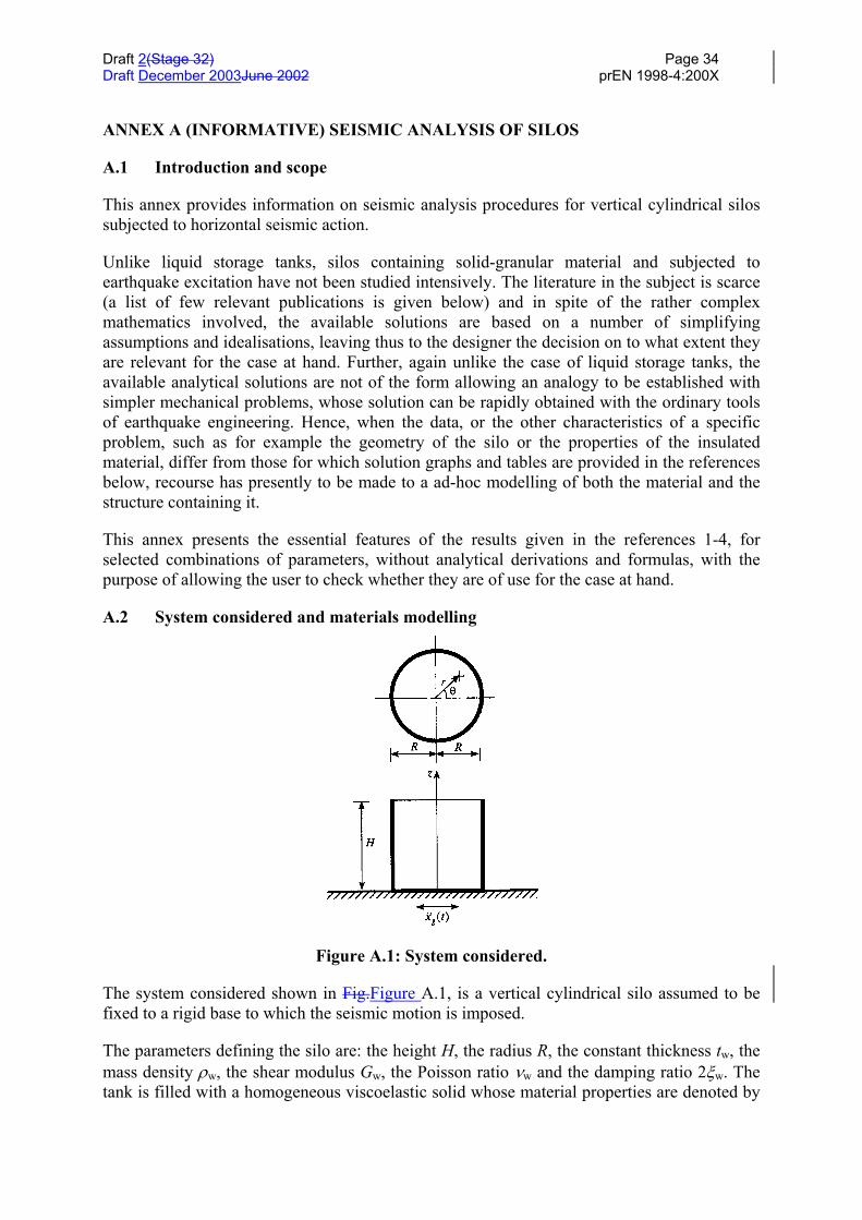
Draft 2(Stage 32) Page 34Draft December 2003June 2002 prEN 1998-4:200X
ANNEX A (INFORMATIVE) SEISMIC ANALYSIS OF SILOS
A.1 Introduction and scope
This annex provides information on seismic analysis procedures for vertical cylindrical silossubjected to horizontal seismic action.
Unlike liquid storage tanks, silos containing solid-granular material and subjected toearthquake excitation have not been studied intensively. The literature in the subject is scarce(a list of few relevant publications is given below) and in spite of the rather complexmathematics involved, the available solutions are based on a number of simplifyingassumptions and idealisations, leaving thus to the designer the decision on to what extent theyare relevant for the case at hand. Further, again unlike the case of liquid storage tanks, theavailable analytical solutions are not of the form allowing an analogy to be established withsimpler mechanical problems, whose solution can be rapidly obtained with the ordinary toolsof earthquake engineering. Hence, when the data, or the other characteristics of a specificproblem, such as for example the geometry of the silo or the properties of the insulatedmaterial, differ from those for which solution graphs and tables are provided in the referencesbelow, recourse has presently to be made to a ad-hoc modelling of both the material and thestructure containing it.
This annex presents the essential features of the results given in the references 1-4, forselected combinations of parameters, without analytical derivations and formulas, with thepurpose of allowing the user to check whether they are of use for the case at hand.
A.2 System considered and materials modelling
Figure A.1: System considered.
The system considered shown in Fig.Figure A.1, is a vertical cylindrical silo assumed to befixed to a rigid base to which the seismic motion is imposed.
The parameters defining the silo are: the height H, the radius R, the constant thickness tw, themass density ρw, the shear modulus Gw, the Poisson ratio νw and the damping ratio 2ξw. Thetank is filled with a homogeneous viscoelastic solid whose material properties are denoted by

Draft 2(Stage 32) Page 35Draft December 2003June 2002 prEN 1998-4:200X
ρ, G, ν and 2ξ in the same order as for the silo. These data completely define the elasticbehaviour of the system, in particular periods and mode shapes of both the separate parts (i.e.,the silo and the column of the filling material) and the combined system. In what follows themain results will be shown for the (more unfavourable) case in which the internal solid can beassumed as fully bonded to the internal face of the cylinder (rough interface).
A.3: Maximum responses of the system
The response parameters considered are: the profile along the height of the maximumpressures on the wall (these pressures vary along the circumference as cosθ), the maximumbase shear, and the height (from the base) at which the resultant of the inertia forces islocated. In the results shown subsequently, the mass of the silo is assumed to be negligiblecompared to the mass of the retained material. Corrections to account for walls inertia, whenthe above assumption is not satisfied, are given in ref. 4.
Following the approach used in ref. 1-4, the results are given as the product of two terms. Thefirst one represents the response to a constant acceleration acting at the base. This part of thetotal response is indicated “static”. The total reponse (due to an arbitrary seismic excitation) isobtained by multiplying the static component by an appropriate amplification factor.
Static effects
Figure A.2: Normalised values of base shear for statically excited systems with differentwall flexibilities and slenderness ratios; mw = 0 and ν = 1/3.
The static value of the maximum base shear in the silo wall: (Qb)st is plotted in Fig.Figure A.2as function of the relative flexibility factor:
www tG
RGd ⋅= (A.1)
for different slenderness ratios H/R. The values are normalised with respect to the product:gXm && , where m is the total contained mass and gX&& is the constant acceleration value. The
normalising factor is thus the inertia force that would act on the mass if it were a rigid body.The results in Fig.Figure A.2 are for ν = 1/3. It is observed from Fig.Figure A.2 that the baseshear, and hence the proportion of the contained mass contributing to this shear, is highlydependent on both the slenderness ratio H/R and the relative flexibility factor dw. For rigid (dw
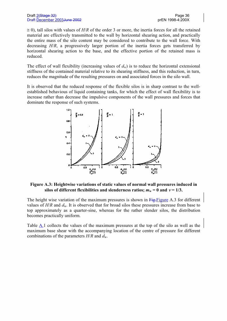
Draft 2(Stage 32) Page 36Draft December 2003June 2002 prEN 1998-4:200X
≅ 0), tall silos with values of H/R of the order 3 or more, the inertia forces for all the retainedmaterial are effectively transmitted to the wall by horizontal shearing action, and practicallythe entire mass of the silo content may be considered to contribute to the wall force. Withdecreasing H/R, a progressively larger portion of the inertia forces gets transferred byhorizontal shearing action to the base, and the effective portion of the retained mass isreduced.
The effect of wall flexibility (increasing values of dw) is to reduce the horizontal extensionalstiffness of the contained material relative to its shearing stiffness, and this reduction, in turn,reduces the magnitude of the resulting pressures on and associated forces in the silo wall.
It is observed that the reduced response of the flexible silos is in sharp contrast to the well-established behavious of liquid containing tanks, for which the effect of wall flexibility is toincrease rather than decrease the impulsive components of the wall pressures and forces thatdominate the response of such systems.
Figure A.3: Heightwise variations of static values of normal wall pressures induced insilos of different flexibilities and slenderness ratios; mw = 0 and ν = 1/3.
The height wise variation of the maximum pressures is shown in Fig.Figure A.3 for differentvalues of H/R and dw. It is observed that for broad silos these pressures increase from base totop approximately as a quarter-sine, whereas for the rather slender silos, the distributionbecomes practically uniform.
Table A.1 collects the values of the maximum pressures at the top of the silo as well as themaximum base shear with the accompanying location of the centre of pressure for differentcombinations of the parameters H/R and dw.

Draft 2(Stage 32) Page 37Draft December 2003June 2002 prEN 1998-4:200X
Table A.1: Static values of top radial pressure σst(1), base shear (Qb)st, andeffective height h; mw = 0, ν = 1/3 and rough interface.
Total seismic response
Base shear
The maximum total dynamic base shear: (Qb)max, is obtained by multiplying thecorresponding static value (Qb)st times the so-called dynamic amplification factor AF.Numerical studies show that this latter factor is essentially a function of the flexibility ratiodw, of the slenderness ratio H/R and of the fundamental period of the solid-silo system. Withrespect to this latter parameter, AF remains close to unity in the range of very short periods(i.e. for rigid tanks), then increases sharply and remains practically constant up to the periodsof 0,5-0,6sec, beyond which it decreases rapidly to values lower than unity. Since the range ofperiods of practical importance is 0,1-0,5sec, within which AF does not vary significantly, theaverage value of AF in this range has been evaluated (using as input motion the El Centro N-S, 1940 record) and is reported in Fig.Figure A.4 as a funcion of dw and for a number of H/Rvalues. The figure shows that for rigid silos AF increases fast with the increase of theslenderness ratio H/R, while the dependence tends to vanish for flexible silos.
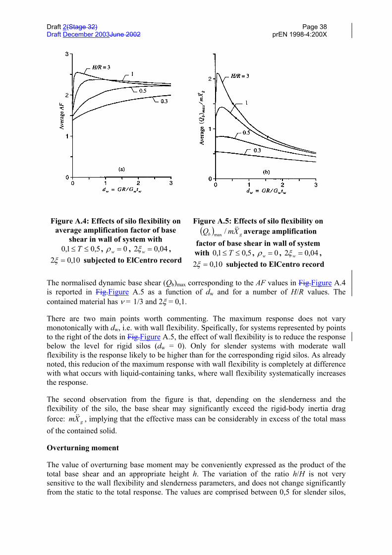
Draft 2(Stage 32) Page 38Draft December 2003June 2002 prEN 1998-4:200X
Figure A.4: Effects of silo flexibility onaverage amplification factor of base
shear in wall of system with5,01,0 ≤≤ T , 0=wρ , 04,02 =wξ ,
10,02 =ξ subjected to ElCentro record
Figure A.5: Effects of silo flexibility on( ) gb XmQ &&/max average amplification
factor of base shear in wall of systemwith 5,01,0 ≤≤ T , 0=wρ , 04,02 =wξ ,
10,02 =ξ subjected to ElCentro record
The normalised dynamic base shear (Qb)max corresponding to the AF values in Fig.Figure A.4is reported in Fig.Figure A.5 as a function of dw and for a number of H/R values. Thecontained material has ν = 1/3 and 2ξ = 0,1.
There are two main points worth commenting. The maximum response does not varymonotonically with dw, i.e. with wall flexibility. Speifically, for systems represented by pointsto the right of the dots in Fig.Figure A.5, the effect of wall flexibility is to reduce the responsebelow the level for rigid silos (dw = 0). Only for slender systems with moderate wallflexibility is the response likely to be higher than for the corresponding rigid silos. As alreadynoted, this reducion of the maximum response with wall flexibility is completely at differencewith what occurs with liquid-containing tanks, where wall flexibility systematically increasesthe response.
The second observation from the figure is that, depending on the slenderness and theflexibility of the silo, the base shear may significantly exceed the rigid-body inertia dragforce: gXm && , implying that the effective mass can be considerably in excess of the total massof the contained solid.
Overturning moment
The value of overturning base moment may be conveniently expressed as the product of thetotal base shear and an appropriate height h. The variation of the ratio h/H is not verysensitive to the wall flexibility and slenderness parameters, and does not change significantlyfrom the static to the total response. The values are comprised between 0,5 for slender silos,
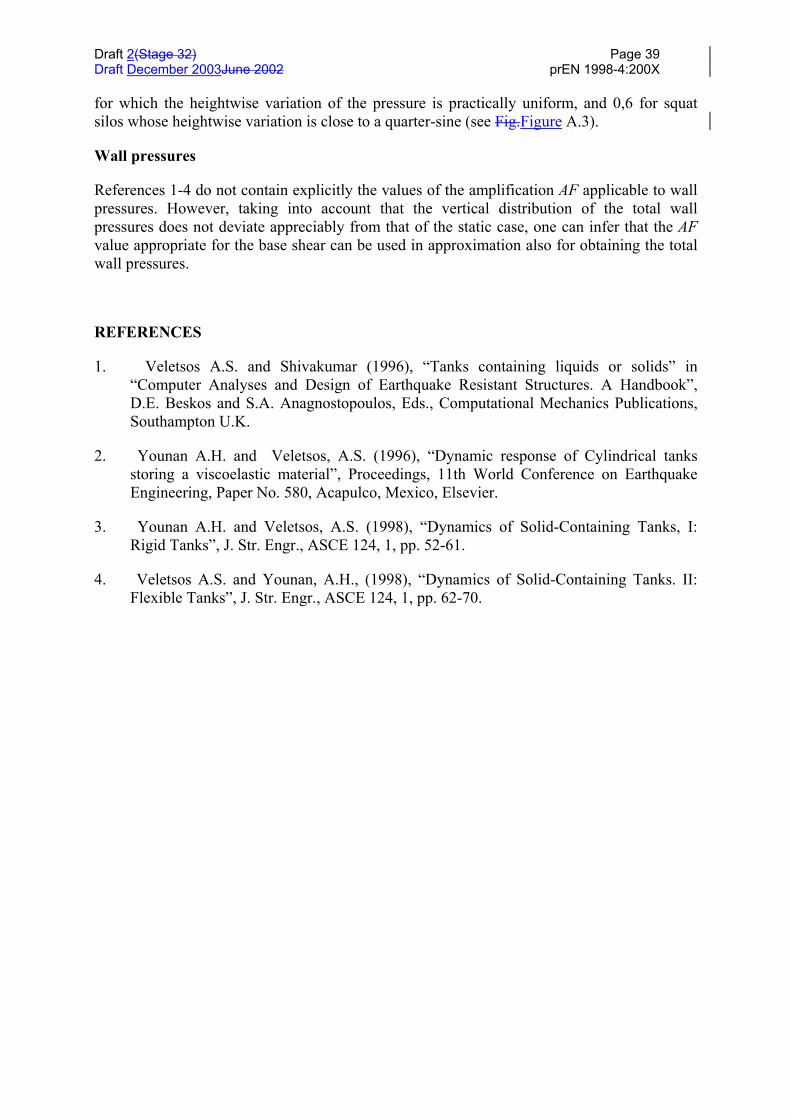
Draft 2(Stage 32) Page 39Draft December 2003June 2002 prEN 1998-4:200X
for which the heightwise variation of the pressure is practically uniform, and 0,6 for squatsilos whose heightwise variation is close to a quarter-sine (see Fig.Figure A.3).
Wall pressures
References 1-4 do not contain explicitly the values of the amplification AF applicable to wallpressures. However, taking into account that the vertical distribution of the total wallpressures does not deviate appreciably from that of the static case, one can infer that the AFvalue appropriate for the base shear can be used in approximation also for obtaining the totalwall pressures.
REFERENCES
1. Veletsos A.S. and Shivakumar (1996), “Tanks containing liquids or solids” in“Computer Analyses and Design of Earthquake Resistant Structures. A Handbook”,D.E. Beskos and S.A. Anagnostopoulos, Eds., Computational Mechanics Publications,Southampton U.K.
2. Younan A.H. and Veletsos, A.S. (1996), “Dynamic response of Cylindrical tanksstoring a viscoelastic material”, Proceedings, 11th World Conference on EarthquakeEngineering, Paper No. 580, Acapulco, Mexico, Elsevier.
3. Younan A.H. and Veletsos, A.S. (1998), “Dynamics of Solid-Containing Tanks, I:Rigid Tanks”, J. Str. Engr., ASCE 124, 1, pp. 52-61.
4. Veletsos A.S. and Younan, A.H., (1998), “Dynamics of Solid-Containing Tanks. II:Flexible Tanks”, J. Str. Engr., ASCE 124, 1, pp. 62-70.
Draft 2(Stage 32) Page 40Draft December 2003June 2002 prEN 1998-4:200X
EUROPEAN PRESTANDARD prENV 1998-4
ANNEX BA (IINFORMATIVE) SEISMIC ANALYSIS PROCEDURES FOR TANKS
B.1 Introduction and scope
This Annex provides information on seismic analysis procedures for tanks subjected tohorizontal and vertical excitation and having the following characteristics:
a) cylindrical shape, with vertical axis and circular or rectangular cross-section;
b) rigid or flexible foundation;
c) fully or partially anchored to the foundation.
Extensions required for dealing with elevated tanks are briefly discussed, as it is the case forcylindrical tanks with horizontal axis.
A rigorous analysis of the phenomenon of dynamic interaction between the motion of thecontained fluid, the deformation of the tank walls and that of the underlying foundation soil,including possible uplift, is a problem of considerable analytical complexity and requiringunusually high computational resources and efforts. Although solutions to the more simplecases of seismic response of tanks are known from the early seventies, progress in thetreatment of the more complex ones is continuing up to the present, and it is still incomplete.
Numerous studies are being published, offering new, more or less approximate, proceduresvalid for specific design situations. Since their accuracy is problem-dependent, a properchoice requires a certain amount of specialiazed knowledge from the designer. Attention iscalled to the importance of a uniform level of accuracy across the design process: it would notbe consistent, for ex., to select an accurate solution for the determination of the hydrodynamicpressures, and then not to use a correspondingly refined mechanical model of the tank (e.g., aF.E. model) for evaluating the stresses due to the pressures.
The necessary limitations in the scope and space of this Annex do not allow to go beyond adetailed presentation of the seismic design procedure for the simplest of all cases: rigidcircular tanks anchored to a rigid base. For all the situations which make the problem morecomplex, as for example. the flexibility of the tank, and/or that of the foundation soil, and/orthat of the anchoring system, since exact solutions are either complicated and lengthy, or nonexisting, a brief explanation is given of the physical phenomena distinguishing the particularsituation from the reference case, and approximate solutions are either summarized orreference is made to pertinent literature.
At present, the most comprehensive documents giving guidelines for the seismic design oftanks are the ASCE volume: "Guidelines for the seismic design of oil and gas pipelinesystems", 1984, ref. [5], and the Recommendations of a New Zealand Study Group: "SeismicDesign of Storage Tanks", 1986, ref. [10]. Although more than ten years old they are stillvaluable in that they cover in detail a wide range of cases. Both documents are used assources for the present Annex.

Draft 2(Stage 32) Page 41Draft December 2003June 2002 prEN 1998-4:200X
B.2 Vertical rigid circular tanks
B.2.1 Horizontal earthquake excitation
The complete solution of the Laplace equation for the motion of the fluid contained in a rigidcylinder can be expressed as the sum of two separate contributions, called "rigid impulsive",and "convective", respectively. The "rigid impulsive" component of the solution satisfiesexactly the boundary conditions at the walls and at the bottom of the tank (compatibilitybetween the velocities of the fluid and of the tank), but gives (incorrectly, due to the presenceof the waves) zero pressure at the free surface of the fluid. A second term must therefore beadded, which does not alter those boundary conditions that are already satisfied, and re-establishes the correct equilibrium condition at the top.
Use is made of a cylindrical coordinate system: r, z, θ, with origin at the centere of the tankbottom, and the z axis vertical. The height and the radius of the tank are denoted by H and R,respectively, ρ is the mass density of the fluid, and ξ = r/R, ς = z/H, are the nonadimensionalcoordinates.
B.2.1.1 Rigid impulsive pressure
The spatial-temporal variation of this component is given by the expression:
( ) ( ) ( )tAHCtp gii cos,,,, θρςξθςξ = (B.1)
where:
( ) ( )( ) ( )
−= ∑
∞
=
ξγ
νςννγν
ςξ n1n2
nn'1
n
i cos/1, I
IC
on(B.2)
in which:
RHn /;2
12n =
+= γπν
( )I1 ⋅ and ( )I1' ⋅ denote the modified Bessel function of order 1 and its derivative5.
The time-dependence of the pressure pi in eq. (B.1) is given by the function Ag(t), whichrepresents here the free-field motion of the ground (the peak value of Ag(t) is denoted by ag).The distribution along the height of pi in eq. (B.1) is given by the function Ci and isrepresented in Fig.Figure B.1(a) for ξ = 1 (i.e. at the wall of the tank) and cosθ = 1 (i.e. on theplane which contains the motion), normalized to ρR ag and for three values ofγ = H/R.
5 The derivative can be expressed in terms of the modified Bessel functions of order 0 and 1 as:
( )( )
( )( )
I xdI x
dx I xI x
x11
01' = = +
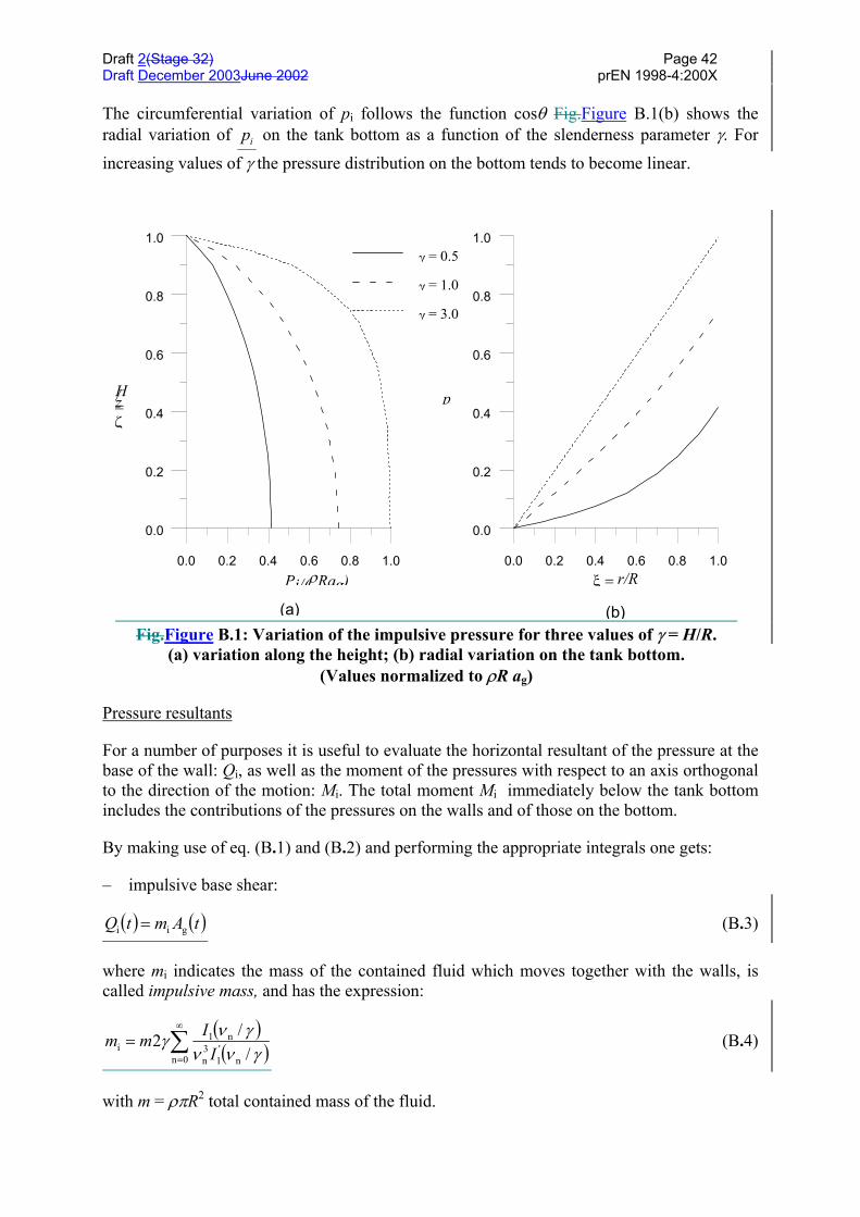
Draft 2(Stage 32) Page 42Draft December 2003June 2002 prEN 1998-4:200X
The circumferential variation of pi follows the function cosθ Fig.Figure B.1(b) shows theradial variation of pi on the tank bottom as a function of the slenderness parameter γ. For
increasing values of γ the pressure distribution on the bottom tends to become linear.
0.0 0.2 0.4 0.6 0.8 1.0Pi/(ρRag)
0.0
0.2
0.4
0.6
0.8
1.0
ζ=z/H
γ = 0.5
γ = 1.0
γ = 3.0
0.0 0.2 0.4 0.6 0.8 1.0ξ = r/R
0.0
0.2
0.4
0.6
0.8
1.0
p
(a) (b)Fig.Figure B.1: Variation of the impulsive pressure for three values of γ = H/R.
(a) variation along the height; (b) radial variation on the tank bottom.(Values normalized to ρR ag)
Pressure resultants
For a number of purposes it is useful to evaluate the horizontal resultant of the pressure at thebase of the wall: Qi, as well as the moment of the pressures with respect to an axis orthogonalto the direction of the motion: Mi. The total moment Mi immediately below the tank bottomincludes the contributions of the pressures on the walls and of those on the bottom.
By making use of eq. (B.1) and (B.2) and performing the appropriate integrals one gets:
– impulsive base shear:
( ) ( )tAmtQ gii = (B.3)
where mi indicates the mass of the contained fluid which moves together with the walls, iscalled impulsive mass, and has the expression:
( )( )∑
∞
=
=0n n
'1
3n
n1i /
/2γνν
γνγI
Imm (B.4)
with m = ρπR2 total contained mass of the fluid.
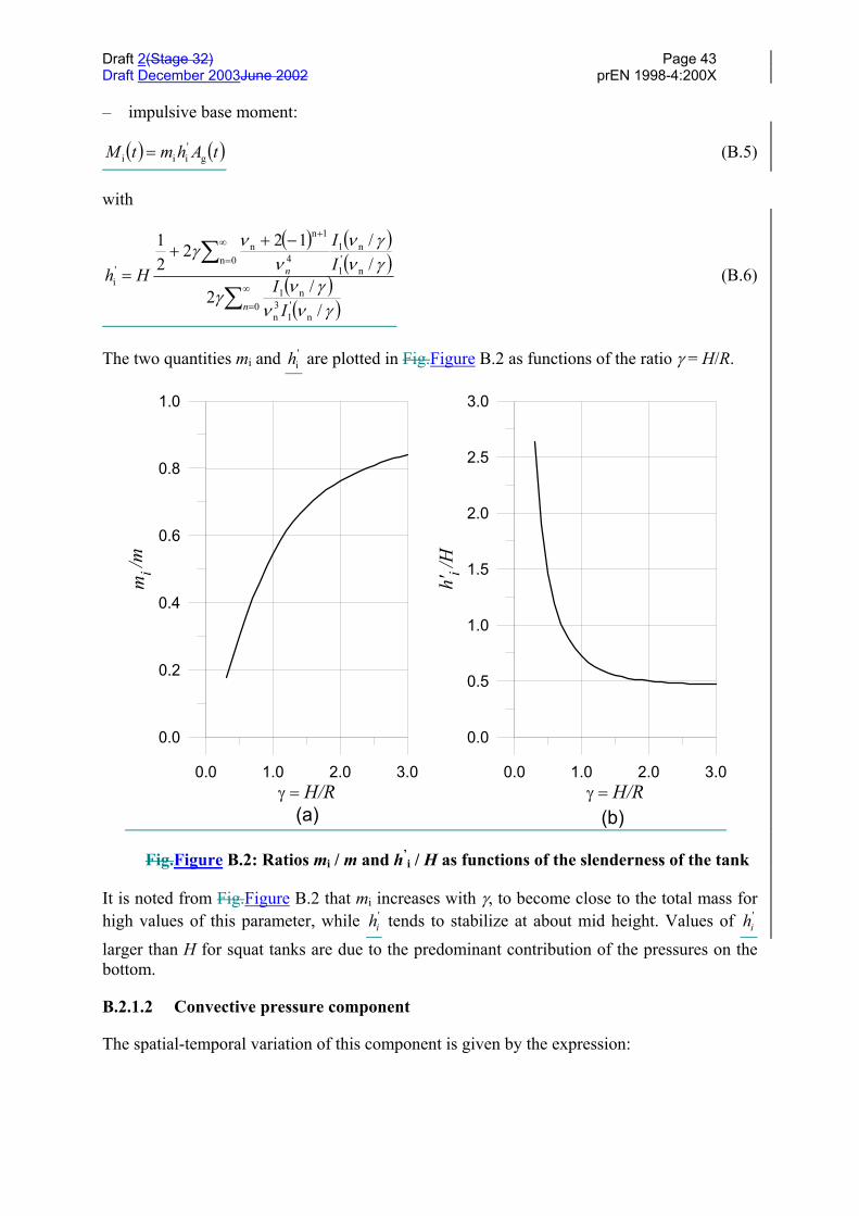
Draft 2(Stage 32) Page 43Draft December 2003June 2002 prEN 1998-4:200X
– impulsive base moment:
( ) ( )tAhmtM g'iii = (B.5)
with
( ) ( )( )
( )( )∑
∑∞
=
∞
=
+−++
=
0n
'1
3n
n1
0nn
'1
n14
1nn
'i
//2
//122
21
n
n
II
II
Hh
γννγνγ
γνγν
ννγ
(B.6)
The two quantities mi and 'ih are plotted in Fig.Figure B.2 as functions of the ratio γ = H/R.
0.0 1.0 2.0 3.0γ = H/R
0.0
0.2
0.4
0.6
0.8
1.0
mi /m
0.0 1.0 2.0 3.0γ = H/R
0.0
0.5
1.0
1.5
2.0
2.5
3.0
h'i /
H
(a) (b)
Fig.Figure B.2: Ratios mi / m and h’i / H as functions of the slenderness of the tank
It is noted from Fig.Figure B.2 that mi increases with γ, to become close to the total mass forhigh values of this parameter, while '
ih tends to stabilize at about mid height. Values of 'ih
larger than H for squat tanks are due to the predominant contribution of the pressures on thebottom.
B.2.1.2 Convective pressure component
The spatial-temporal variation of this component is given by the expression:

Draft 2(Stage 32) Page 44Draft December 2003June 2002 prEN 1998-4:200X
( ) ( ) ( ) ( )tAJtp nn11n
nnc coscosh,,, θξλγςλψρθςξ ∑∞
=
= (B.7)
with
( ) ( ) ( )γλλλψ
nhJR
cos12
n12n
n −= (B.8)
λ λ λ1 2 31 8112 5 3314 8 5363= = =, , ,
J1 = Bessel function of the first order
An(t) = response acceleration of a single degree of freedom oscillator having a frequencyωcn:
( )γλλω nn2
cn tan hR
g= (B.9)
and a damping factor value appropriate for the fluid.
Eq. (B.7) shows that the total pressure is the combination of an infinite number of modalterms, each one corresponding to a wave form of the oscillating liquid. Only the firstoscillating, or sloshing, mode and frequency, needs in most cases to be considered for designpurposes.
The vertical distribution of the sloshing pressures for the first two modes are shown inFig.Figure B.3(a), while Fig.Figure B.3(b) gives the values of the first two frequencies, asfunctions of the ratio H/R.
0.0 0.2 0.4 0.6 0.8 1.0p/(ρ R A(t))
0.0
0.2
0.4
0.6
0.8
1.0
ζ =
z/H
2nd Mode
1st Mode
γ = 0.5
γ = 1.0
γ = 3.0
0.0 0.5 1.0 1.5 2.0 2.5 3.0γ = H/R
0.5
1.0
1.5
2.0
2.5
ω √
(R/g
)
1st th Mode
2nd Mode
(a) (b)
Fig.Figure B.3: Variation of the first two modes sloshing pressures along the height (a)and values of the first two sloshing frequencies as functions of γ (b)
One can observe from Fig.Figure B.3 that in squat tanks the sloshing pressures maintain
Draft 2(Stage 32) Page 45Draft December 2003June 2002 prEN 1998-4:200X
relatively high values down to the bottom, while in slender tanks the sloshing effect issuperficial.
For the same value of the response acceleration, the contribution of the second mode is seento be negligible. The other interesting result from Fig.Figure B.3(b) is that the sloshingfrequencies become almost independent of the parameter γ, when this is larger than about 1.
The value of ωc1 in this case is approximately given by the expression:
( )sRR metrein/2,4c1 =ω (B.10)
which, for the usual values of R in petrochemical plants yields periods of oscillation of theorder of few seconds (for instance, Tc1 = 4,7 sec for R = 10 m).
Pressure resultants
In a way analogous to that followed for the impulsive component one may arrive at theexpressions for the base shear resultant and the total moment immediately below the bottomplate of the tank.
The base shear is given by:
( ) ( )∑∞
=
=1n
ncnc tAmtQ (B.11)
with the nth modal convective mass:
( )( )1
tan22nn
ncn −
=λλγ
γλhmm (B.12)
From eq. (B.11) one can note that the total shear force is given by the instantaneous sum ofthe forces contributed by the (infinite) oscillators having masses mcn, attached to the rigid tankby means of springs having stiffnesses: cn
2nn mK ω= . The tank is subjected to the ground
acceleration Ag(t) and the masses respond with accelerations An(t).
From Fig.Figure B.3 (and the following, Fig.Figure B.4) one can verify that only the first ofthe sloshing masses needs to be considered.
The total moment can be expressed as:
( ) ( )( ) ( )∑∑∞
=
∞
=
==11 n
cncncnn
ncnc htQhtAmtM (B.13)
where hcn is the level where the equivalent oscillator has to be applied in order to give thecorrect value of Mcn:
( )( )
−+=
γλγλγλ
nn
ncn sin
cos21hhHh (B.14)

Draft 2(Stage 32) Page 46Draft December 2003June 2002 prEN 1998-4:200X
The values of mc1 and mc2, and the corresponding values of hc1 and hc2 are shown inFig.Figure B.4, as functions of γ.
0.0 0.5 1.0 1.5 2.0 2.5 3.0γ = H/R
0.0
0.2
0.4
0.6
0.8
mc/m
0.0 0.5 1.0 1.5 2.0 2.5 3.0γ = H/R
0.0
1.0
2.0
3.0
4.0
h c/H
1st Mode
2nd Mode
(a) (b)
Fig.Figure B.4: First two sloshing modal masses Fig.(a) and corresponding heights hc1
and hc2 Fig.(b) as functions of γ
B.2.1.3 Height of the convective wave
The predominant contribution to the sloshing wave height is provided by the first mode, andthe expression of the peak at the edge is:
( )c1emax 84,0 TSRd = (B.15)
where Se(⋅) is the appropriate elastic acceleration response spectrum, expressed in g(acceleration of gravity).
B.2.1.4 Combination of impulsive and convective pressures
The time-history of the total pressure is the sum of the two time-histories, the impulsive onebeing driven by Ag(t), the convective one by Ac1(t) (neglecting higher order components).
If, as it is customary in design practice, a response spectrum approach is preferred, theproblem of suitably combining the two maxima arises. Given the generally wide separationbetween the central frequencies of the ground motion and the sloshing frequency, the “squareroot of the sum of squares” rule may become unconservative, so that the alternative, upperbound, rule of adding the absolute values of the two maxima is recommended for general use.
B.2.1.5 Effect of walls inertia
For steel tanks, the inertia forces acting on the shell due to its own mass are small incomparison with the hydrodynamic forces, and can normally be neglected. For concrete tankshowever, the wall inertia forces may not be completely negligible. The inertia forces arecontained in the same vertical plane of the seismic excitation; considering their componentnormal to the surface of the shell one has for the pressure the following expression:
Draft 2(Stage 32) Page 47Draft December 2003June 2002 prEN 1998-4:200X
( )tAsp gww cosθρ= (B.16)
with
ρw = mass density of the wall material
s = wall thickness
This pressure component, which is constant along the height, has to be added to the impulsivecomponent given by eq. (B.1). The total shear at the base is obtained by simply consideringthe total mass of the tank multiplied by the acceleration of the ground.
B.2.2 Vertical earthquake excitation
The hydrodynamic pressure on the walls of a rigid tank due to a vertical ground accelerationAν(t) is given by:
( ) ( ) ( )tAHtp vv ςρς −= 1,r (B.17)
B.2.3 Combination of pressures due to horizontal and vertical excitation
The peak combined pressure due to horizontal and vertical excitation can be obtained byapplying the rule given in 3.2.
B.3 Vertical deformable circular tanks
B.3.1 Horizontal earthquake excitation
When the tank cannot be considered as rigid (this is almost always the case for steel tanks) thecomplete solution of the Laplace equation is ordinarily sought in the form of the sum of threecontributions, referred to as: "rigid impulsive", "sloshing" and "flexible".
The third contribution is new with respect to the case of rigid tanks: it satisfies the conditionthat the radial velocity of the fluid along the wall equals the deformation velocity of the tankwall, plus the conditions of zero vertical velocity at the tank bottom and zero pressure at thefree surface of the fluid.
Since the deformation of the wall is also due to the sloshing pressures, the sloshing and theflexible components of the solution are theoretically coupled, a fact which makes thedetermination of the solution quite involved. Fortunately, the dynamic coupling is very weak,due to the separation which exists between the frequencies of the two motions, and this allowsto determine the third component independently of the others with almost complete accuracy.The rigid impulsive and the sloshing components examined in B.2 remain thereforeunaffected.
No closed-form expression is possible for the flexible component, since the pressuredistribution depends on the modes of vibration of the tank-fluid system, and hence on thegeometric and stiffness properties of the tank. These modes cannot be obtained directly fromusual eigenvalue algorithms, since the participating mass of the fluid is not known a priori andalso because only the modes of the type: f (ς,θ) = f (θ) cosθ are of interest (and these modesmay be laborious to find among all other modes of a tank).

Draft 2(Stage 32) Page 48Draft December 2003June 2002 prEN 1998-4:200X
Assuming the modes as known (only the fundamental one is normally sufficient, so that in thefollowing expressions both the mode index and the summation over all modal contributionsare dropped) the flexible pressure distribution has the form:
( ) ( ) ( )tAdHtpn
f0
nnf coscos,, θςνψρθς ∑∞
=
= (B.18)
with:
( ) ( )
( ) ( ) ( )∫ ∑
∫ ∑
+
+
=∞
=
∞
=
1
0 0 nns
1
0 0 n'n
s
cos
cos
ςςνςρρς
ςςνρρς
ψddf
Hsf
dbHsf
n
n
(B.19)
( ) ( )( )γν
γνν /
/12n
'1
n12n
n'n I
Ib −= (B.20)
( ) ( ) ( )( )γν
γνν
ςςνς
//cos
2n
'1
n1
n
1
0 nn I
Idfd ∫= (B.21)
ρs is the mass density of the shell, s is its thickness and Af(t) is the response acceleration(relative to its base) of a simple oscillator having the fundamental frequency and dampingfactor of the first mode.
In most cases of flexible tanks, the pressure pf(⋅) in eq. (B.18) provides the predominantcontribution to the total pressure, due to the fact that, while the rigid impulsive term (eq.(B.1)) varies with the ground acceleration Ag(t), the flexible term (eq. (B.18)) varies with theresponse acceleration which, given the usual range of periods of the tank-fluid systems, isconsiderably amplified with respect to Ag(t).
For the determination of the first mode shape of the tank, the following iterative procedure issuggested in ref. [2]. Starting from a trial shape f (ς) and denoting with fi (ς) the onecorresponding to the i-th iteration step, an "effective" mass of the shell is evaluated as:
( ) ( )( ) ( )
ρ ςς
ς ςρi s
i
i sp
g s f= +
2(B.22)
where ( )psi ς is the amplitude of the pressure evaluated with eq. (B.18) at the i-th step, and
s(ς) is the thickness of the shell, respectively.
The effective density from eq. (B.22) can then be used in a structural analysis of the tank toevaluate the (i+1)th mode shape, and so forth until convergence is achieved.
The fundamental frequency of the tank-fluid system can be evaluated by means of thefollowing approximate expression:

Draft 2(Stage 32) Page 49Draft December 2003June 2002 prEN 1998-4:200X
( )( ) ( )f E s H R gs = ς ρ γ/ //1 2
2 (with ς= 1/3) (B.23)
with
( )g γ γ γ= − +0 01675 0 15 0 462, , , (B.24)
Pressure resultants
Starting from eq. (B.18), the resultant base shear and total moment at the base can beevaluated, arriving at expressions in the form:
- base shear ( ) ( ) ( )onlymode1stfff tAmtQ = (B.25)
with
( )n
0 n
n
f1 dmm
n∑
∞
=
−=
νψγ (B.26)
- total moment ( ) ( )tAhmtM ffff = (B.27)
with
( ) ( )
( )∑
∑∑∞
=
∞
=
∞
=
−
+
−−
=
0n
n'n
0n
n'1n
0 2n
nn
n
f 1
/21
n
nn
d
IddHh
νγ
νγν
ννγ
(B.28)
B.3.2 Combination of pressures terms due to horizontal excitation
The time-history of the total pressure is, in the case of flexible tanks, the sum of three time-histories: of the rigid impulsive one (eq. (B.1)), of the convective one (eq. (B.7)), and of theflexible one (eq. (B.18)) each of them differently distributed along the height and having adifferent variation with time.
Referring for simplicity to the base shears produced by these pressures (eqs. (B.3), (B.11) and(B.25)) one has:
( ) ( ) ( ) ( )tAmtAmtAmtQn
ff1
ncngi ++= ∑∞
=
(B.29)
where, it is recalled, An(t) is the total or absolute response acceleration of a simple oscillatorof frequency ωn (eq. (B.9)) subjected to a base acceleration Ag(t); while Af(t) is the responseacceleration, relative to the base, of a simple oscillator of frequency ωf (eq. (B.23)), anddamping appropriate for the tank-fluid system, also subjected to Ag(t).
If the individual maxima of the terms in eq. (B.29) are known, which can be achieved byusing a response spectrum of absolute and relative accelerations, the corresponding pressures

Draft 2(Stage 32) Page 50Draft December 2003June 2002 prEN 1998-4:200X
on the tank needed for a detailed stress analysis can be obtained by spreading the resultantover the tank walls and floor according to the relevant distribution.
To expedite the design process, the masses mi, mcn and mf, the latter based on assumed firstmode shapes, have been calculated as functions of the ratio γ, and are available in tabularform or in diagrams, for ex. in ref. [5] and [10].
Use of eq. (B.29) in combination with response spectra, however, poses the problem of howto superimpose the maximaB. Apart from the necessity of deriving a relative accelerationresponse spectrum for Af(t), there is no accurate way of combining the peak of Ag(t) with thatof Af(t).
In fact, since the input and its response cannot be assumed as independent in the relativelyhigh range of frequency under consideration, the “square root of the sum of squares” rule isunconservative. On the other hand, the simple addition of the individual maxima can lead tooverconservative estimates.
Given these difficulties, various approximate approaches based on the theory previouslydiscussed have been proposed.
Two of these, presented as alternatives and illustrated in detail in ref. [5], are due to Veletsos-Yang (V.Y.) and Haroun-Housner (H.H.).
The V.Y. proposal consists essentially in replacing eq. (B.29) with the equation:
( ) ( ) ( )tAmtAmtQn∑
∞
=
+=1
ncnfai (B.30)
i.e., in assuming the entire impulsive mass to respond with the amplified absolute responseacceleration of flexible tank system (Afa(t) = Af(t) + Ag(t)). The maximum of Afa(t) is obtaineddirectly from the appropriate response spectrum.
The V.Y. procedure is an upper bound solution, whose approximation has been proven to beacceptable for H/R ratios not much larger than 1. Above this value, corrections to decrease theconservativeness are suggested. In view of the conservative nature of the method, the effectsof tank inertia may generally be neglected. If desired, the total base shear can be evaluatedapproximately by the expression:
( ) ( ) ( )tAmtQ faow ⋅⋅= ε (B.31)
where Afa(t) is the pseudoacceleration response of the tank-fluid system, and (εo⋅m) is theeffective participating mass of the tank wall in the first mode, where m is the total mass of thetank and the factor εo may be determined approximately from:
H/R 0,5 1,0 3,0
εo 0,5 0,7 0,9
The H.H. proposal starts by writing eq. (B.29) in the form:
Draft 2(Stage 32) Page 51Draft December 2003June 2002 prEN 1998-4:200X
( ) ( ) ( ) ( ) ( )( )tAtAmtAmtAmtQn
gfafn1
cngi −++= ∑∞
=
(B.32)
which can be re-arranged as:
( ) ( ) ( ) ( ) ( )tAmtAmtAmmtQn
faf1
ncngfi ++−= ∑∞
=
(B.33)
i.e., in a form suitable for the use of the response spectrum.
The masses mi and mj are given in graphs as functions of H/R and s/R, together with theheights at which these masses must be located to yield the correct value of the moment (seeref. [5]).
The effects of the inertia of the tank wall are incorporated in the values of the masses and oftheir heights.
The “square root of the sum of squares” rule is used to combine the maximum values of thethree components in eq. (B.33).
In the H.H. approach, the problem of distributing heightwise the total shear force at the base issolved by assuming a uniform pressure distribution over the tank height, which leads to avalue of the hoop stress σ equal to:
σπmax
max=1 Q
H s(B.34)
Along lines similar to those of Veletsos-Yang, an even more simplified approach has beenelaborated by Malhotra (1997) [8], which is reported in full below.
B.3.2.1 Simplified procedure for fixed base cylindrical tanks (Malhotra, 1997)[8]
Model
The hydrodynamic effects in a tank are evaluated by the superposition of these twocomponents: (1) The impulsive component, which represents the action of the liquid near thebase of the tank that moves rigidly with the flexible wall of the tank; and (2) the convectivecomponent, which represents the action of the liquid that experiences sloshing motion nearthe free-surface. In this analysis, the tank-liquid system is modeled by two single-degree-of-freedom systems, one corresponding to the impulsive and the other corresponding to theconvective action. The impulsive and convective responses are combined by taking theirnumerical-sum rather than their root-mean-square value.
Natural periods: The natural periods of the impulsive and the convective responses, inseconds, are
E s/R
iimpH
CTρ
= (B.35)
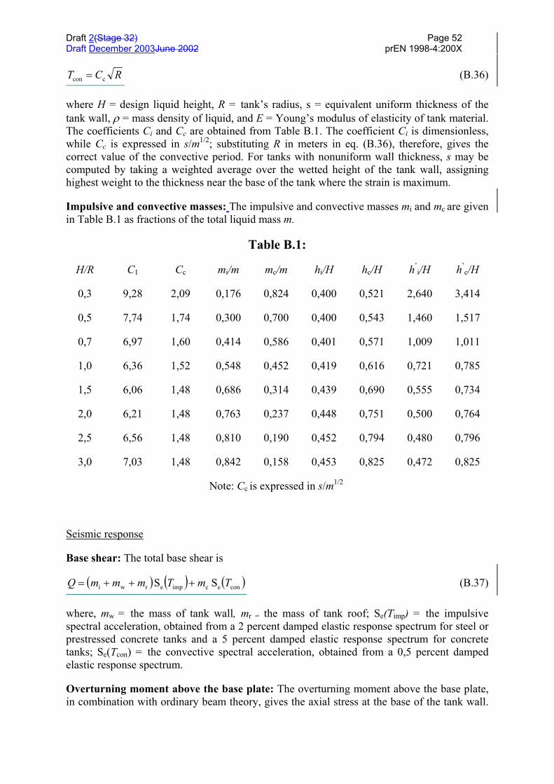
Draft 2(Stage 32) Page 52Draft December 2003June 2002 prEN 1998-4:200X
RCT ccon = (B.36)
where H = design liquid height, R = tank’s radius, s = equivalent uniform thickness of thetank wall, ρ = mass density of liquid, and E = Young’s modulus of elasticity of tank material.The coefficients Ci and Cc are obtained from Table B.1. The coefficient Ci is dimensionless,while Cc is expressed in s/m1/2; substituting R in meters in eq. (B.36), therefore, gives thecorrect value of the convective period. For tanks with nonuniform wall thickness, s may becomputed by taking a weighted average over the wetted height of the tank wall, assigninghighest weight to the thickness near the base of the tank where the strain is maximum.
Impulsive and convective masses: The impulsive and convective masses mi and mc are givenin Table B.1 as fractions of the total liquid mass m.
Table B.1:
H/R C1 Cc mi/m mc/m hi/H hc/H h’i/H h’
c/H
0,3
0,5
0,7
1,0
1,5
2,0
2,5
3,0
9,28
7,74
6,97
6,36
6,06
6,21
6,56
7,03
2,09
1,74
1,60
1,52
1,48
1,48
1,48
1,48
0,176
0,300
0,414
0,548
0,686
0,763
0,810
0,842
0,824
0,700
0,586
0,452
0,314
0,237
0,190
0,158
0,400
0,400
0,401
0,419
0,439
0,448
0,452
0,453
0,521
0,543
0,571
0,616
0,690
0,751
0,794
0,825
2,640
1,460
1,009
0,721
0,555
0,500
0,480
0,472
3,414
1,517
1,011
0,785
0,734
0,764
0,796
0,825
Note: Cc is expressed in s/m1/2
Seismic response
Base shear: The total base shear is
( ) ( ) ( )conecimperwi S S TmTmmmQ +++= (B.37)
where, mw = the mass of tank wall, mr = the mass of tank roof; Se(Timp) = the impulsivespectral acceleration, obtained from a 2 percent damped elastic response spectrum for steel orprestressed concrete tanks and a 5 percent damped elastic response spectrum for concretetanks; Se(Tcon) = the convective spectral acceleration, obtained from a 0,5 percent dampedelastic response spectrum.
Overturning moment above the base plate: The overturning moment above the base plate,in combination with ordinary beam theory, gives the axial stress at the base of the tank wall.
Draft 2(Stage 32) Page 53Draft December 2003June 2002 prEN 1998-4:200X
The net overturning moment immediately above the base plate is
( ) ( ) ( )coneccimperrwwii TShmTShmhm hmM +++= (B.38)
where, hi and hc are the heights of the centroid of the impulsive and convective hydrodynamicwall pressure; they are obtained from Table B1; hw and hr are heights of the centres of gravityof the tank wall and roof, respectively.
Overturning moment below the base plate: The overturning moment immediately belowthe base plate is on account of the hydrodynamic pressure on the tank wall as well as that onthe base plate. It is given by
( ) ( ) ( )conec'
cimperrwwi'
i' TShmTShmhmhmM +++= (B.39)
where heights h’i and h’c are obtained from Table B.1.
If the tank is supported on a ring foundation, moment M should be used to design the tankwall, base anchors and the foundation. If the tank is supported on a mat foundation, momentM should be used to design the tank wall and anchors, while M’ should be used to design thefoundation.
Free-surface wave-height: The vertical displacement of liquid surface due to sloshing isgiven by eq (B.15).
B.3.3 Vertical earthquake excitation
In addition to the pressure pνr(ς,t) given by eq. (B.17), due to the tank moving rigidly in thevertical direction with acceleration Aν(t), a pressure contribution pνf(ς,t) resulting from thedeformability (radial "breathing") of the shell must be considered. This additional term hasthe expression:
( ) ( ) ( )tAHftp vv ff 2cos815,0,
= ςπργς (B.40)
where:
( )f γ = 1,078 + 0,274 ln γ for 0,8 < γ < 4
( )f γ = 1,0 for γ < 0,8
Aνf(t) is the acceleration response function of a simple oscillator having a frequency equal tothe fundamental frequency of the axisymmetric interaction vibration of the tank and the fluid.
The fundamental frequency can be estimated by means of the expression:
( ) ( )( ) ( )
2/1
12
11d 1
241
−
=γνρπ
ςγ
ov IH
sIER
f (with ς = 1/3) (B.41)
Draft 2(Stage 32) Page 54Draft December 2003June 2002 prEN 1998-4:200X
in which γ1 = π / (2γ) and where E and ν are Young modulus and Poisson ratio of the tankmaterial, respectively.
The maximum value of pνf(t) is obtained from the vertical acceleration response spectrum forthe appropriate values of the period and the damping. If soil flexibility is neglected (see B.7)the applicable damping values are those of the material (steel, concrete) of the shell.
The maximum value of the pressure due to the combined effect of the rigid: pνr(⋅) andflexible: pνf(⋅) contributions can be obtained by applying the “square root of the sum ofsquares” rule to the individual maximaB.
B.3.4 Combination of pressures due to horizontal and vertical excitation
The maximum value of the pressure due to the combined effect of horizontal and verticalexcitation can be obtained by applying the “square root of the sum of squares” rule to themaximum pressures produced by each type of excitation.
B.4 Rectangular tanks
For tanks whose walls can be assumed as rigid, a solution of the Laplace equation forhorizontal excitation can be obtained in a form analogous to that described for cylindricaltanks, so that the total pressure is again given by the sum of an impulsive and a convectivecontribution:
( ) ( ) ( )tzptzptzp ,,, ci += (B.42)
The impulsive component has the expression:
( ) ( ) ( )tALzqtzp o gi , ρ= (B.43)
where L is the half-width of the tank in the direction of the seismic action, and the functionqo(z), which gives the variation of pi(⋅) along the height (pi(⋅) is constant in the directionorthogonal to the seismic action), is plotted in Fig.Figure B.5.
The trend and the numerical values of the function qo(z) are quite close to those of acylindrical tank with radius R = L.
The convective pressure component is given by a summation of modal terms (sloshingmodes), each one having a different variation with time. As for cylindrical tanks, thedominant contribution is that of the fundamental mode, that is:
( ) ( ) ( )tALzqtzp 1c1c1 , ρ= (B.44)
where the function qc1(z) is shown in Fig.Figure B.6 together with the 2nd mode contributionqc2(z) and A1(t) is the acceleration response function of a simple oscillator having thefrequency of the first mode, the appropriate value of the damping, and subjected to an inputacceleration Ag(t).
The period of oscillation of the first sloshing mode is:
Draft 2(Stage 32) Page 55Draft December 2003June 2002 prEN 1998-4:200X
T L gHL
1
1 2
2
2 2
=
ππ π
/
tanh
/
(B.45)
Pressure resultants
The base shear and the moment on the foundation could be evaluated on the basis ofexpressions (B.43) and (B.44).
According to reference [10], for design purposes the values of the masses mi and mc1, as wellas of the corresponding heights above the base: h’
i and hc1, calculated for cylindrical tanks andgiven by the expressions (B.4), (B.12) and (B.6), (B.14), respectively, may be adopted forrectangular tanks as well (with L replacing R), with a margin of approximation not exceeding15%.
Flexible walls
Wall flexibility produces generally a significant increase of the impulsive pressures, whileleaving the convective pressures practically unchanged. The reason for this difference is thesame discussed previously for the case of cylindrical tanks, i.e., the uncoupling of the sloshingoscillations from the dynamic deformations of the walls, due to the separation of theirrespective periods.
Studies on the behaviour of flexible rectangular tanks are not numerous, and the solutions arenot amenable to a form suitable for direct use in design: for a recent treatment of the subjectsee for example. ref. [6].
For design purposes, an approximation which is suggested in ref. [10] is to use the samevertical pressure distribution valid for rigid walls, see eq. (B.43) and Fig.Figure B.5, but toreplace the ground acceleration Ag(t) in eq. (B.43) with the response acceleration of a simpleoscillator having the frequency and the damping factor of the first impulsive tank-liquidmode.

Draft 2(Stage 32) Page 56Draft December 2003June 2002 prEN 1998-4:200X
Fig.Figure B.5(a): Dimensionless impulsive pressures on rectangular tank wallperpendicular to direction of earthquake (from ref. [10])
Fig.Figure B.5(b): Peak value of dimensionless impulsive pressures on rectangular wallperpendicular to direction of earthquake (from ref. [10])

Draft 2(Stage 32) Page 57Draft December 2003June 2002 prEN 1998-4:200X
Fig.Figure B.6: Dimensionless convective pressures on rectangular tank wallperpendicular to direction of earthquake (from ref. [10])
This period of vibration is given approximately by:
( ) 2/1ff /2 gdT π= (B.46)
where:
df is the deflection of the wall on the vertical centre-line and at the height of the impulsivemass, when the wall is loaded by a load uniform in the direction of the ground motionand of magnitude: mi g/4BH.
2B is the tank width perpendicular to the direction of loading.
The impulsive mass mi can be obtained from eq. (B.4), but should include the wall mass.
B.5 Horizontal circular cylindrical tanks
The information contained in this section B.5 is taken from ref. [10].
Horizontal cylindrical tanks need to be analyzed both along the longitudinal and thetransverse axis: see Fig.Figure B.7 for nomenclature.
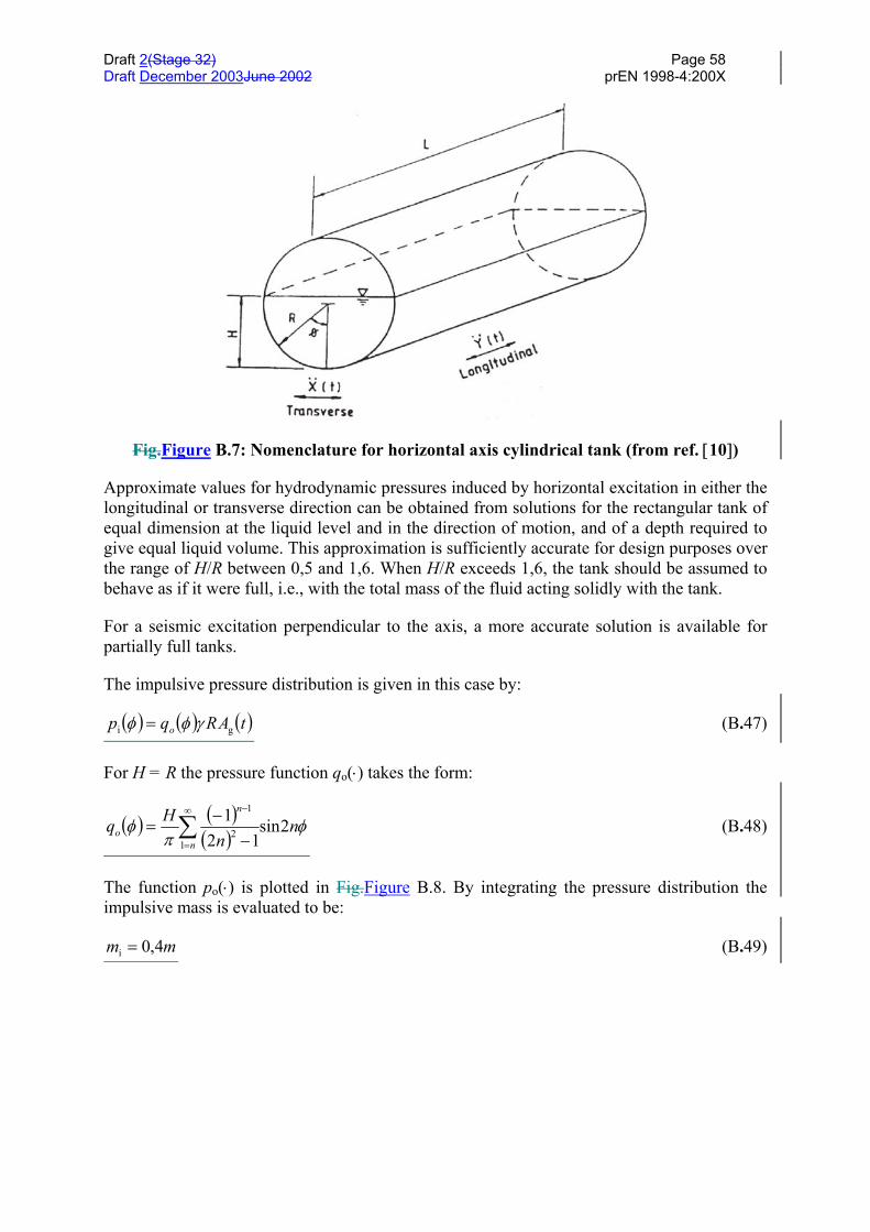
Draft 2(Stage 32) Page 58Draft December 2003June 2002 prEN 1998-4:200X
Fig.Figure B.7: Nomenclature for horizontal axis cylindrical tank (from ref. [10])
Approximate values for hydrodynamic pressures induced by horizontal excitation in either thelongitudinal or transverse direction can be obtained from solutions for the rectangular tank ofequal dimension at the liquid level and in the direction of motion, and of a depth required togive equal liquid volume. This approximation is sufficiently accurate for design purposes overthe range of H/R between 0,5 and 1,6. When H/R exceeds 1,6, the tank should be assumed tobehave as if it were full, i.e., with the total mass of the fluid acting solidly with the tank.
For a seismic excitation perpendicular to the axis, a more accurate solution is available forpartially full tanks.
The impulsive pressure distribution is given in this case by:
( ) ( ) ( )tARqp o gi γφφ = (B.47)
For H = R the pressure function qo(⋅) takes the form:
( ) ( )( )
φπ
φ nn
Hqn
n
o 2sin12
11
2
1
∑∞
=
−
−−
= (B.48)
The function po(⋅) is plotted in Fig.Figure B.8. By integrating the pressure distribution theimpulsive mass is evaluated to be:
mm 4,0i = (B.49)
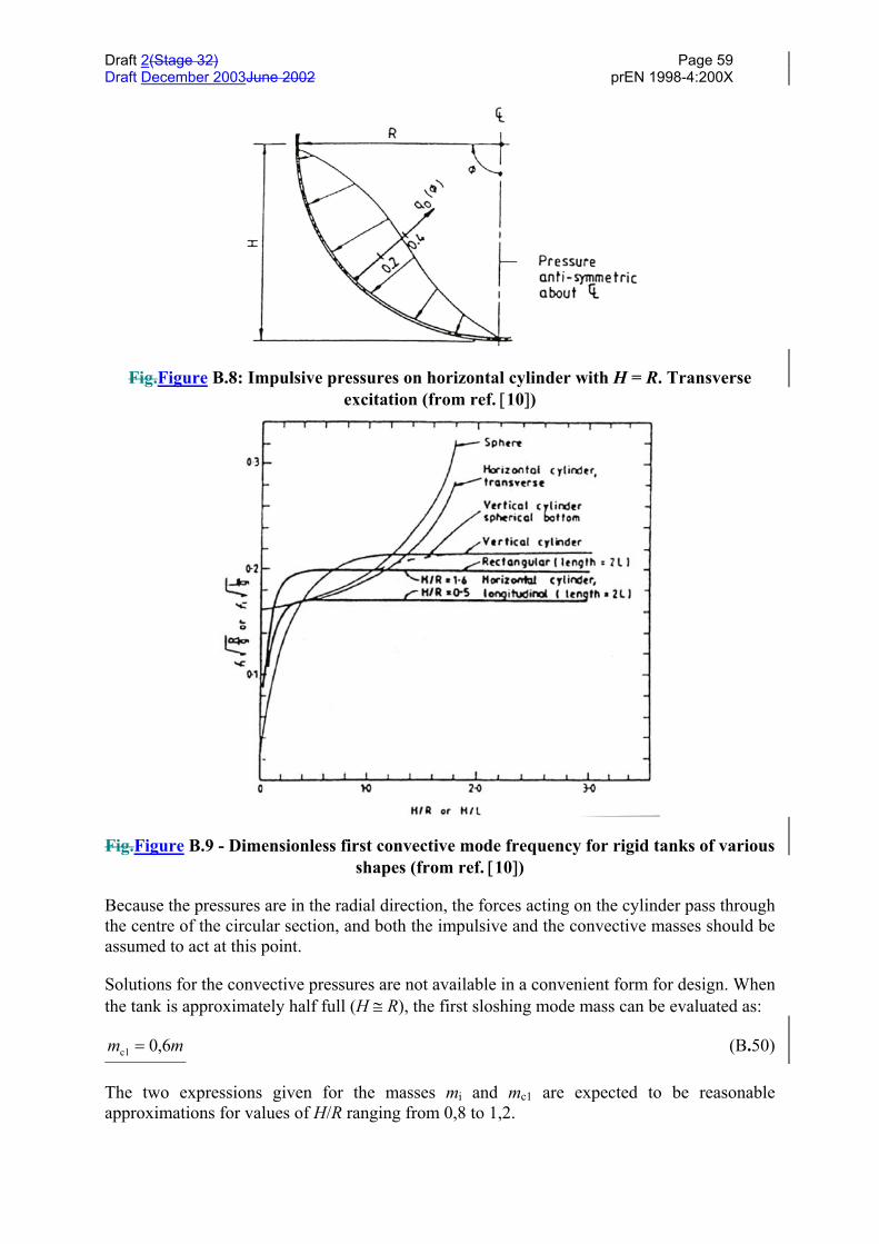
Draft 2(Stage 32) Page 59Draft December 2003June 2002 prEN 1998-4:200X
Fig.Figure B.8: Impulsive pressures on horizontal cylinder with H = R. Transverseexcitation (from ref. [10])
Fig.Figure B.9 - Dimensionless first convective mode frequency for rigid tanks of variousshapes (from ref. [10])
Because the pressures are in the radial direction, the forces acting on the cylinder pass throughthe centre of the circular section, and both the impulsive and the convective masses should beassumed to act at this point.
Solutions for the convective pressures are not available in a convenient form for design. Whenthe tank is approximately half full (H ≅ R), the first sloshing mode mass can be evaluated as:
mm 6,0c1 = (B.50)
The two expressions given for the masses mi and mc1 are expected to be reasonableapproximations for values of H/R ranging from 0,8 to 1,2.
Draft 2(Stage 32) Page 60Draft December 2003June 2002 prEN 1998-4:200X
The first mode sloshing frequencies for tanks of various shapes, including horizontal circularcylinders, with motion along and transverse to the axis, are shown in Fig.Figure B.9.
B.6 Elevated tanks
Elevated tanks can have supporting structures of different types, from simple cylindricaltowers to frame or truss-like structures. For the purpose of the analysis, the presence of theliquid in the supported tank can be accounted for considering two masses: an impulsive massmi located at a height h’
i above the tank bottom (eq. (B.4) and (B.6), respectively), and a massmc1 located at a height hc1 (eq. (B.12) and (B.14), respectively).
The mass mi is rigidly connected to the tank walls, while the mass mc1 is connected to thewalls through a spring of stiffness: Kc1 = ω2
c1 mc1, where ωc1 is given by eq. (B.9).
The mass of the tank is included in the structural model which describes also the supportingstructure. The response of the system can be evaluated using standard modal analysis andresponse spectra methods.
In the simplest possible case, the global model has only two degrees-of-freedom,corresponding to the masses mi and mc1 (the mass of the tank and an appropriate portion of themass of the support has to be added to mi). The mass (mi + ∆m) is connected to the ground bya spring representing the stiffness of the support.
In some cases, the rotational inertia of the mass (mi + ∆m), and the corresponding additionaldegree of freedom, need also to be considered.
In the relatively common case where the shape of the elevated tank is a truncated invertedcone (or close to it), an equivalent cylinder can be considered, having the same volume ofliquid as the real tank, and a diameter equal to that of the cone at the level of the liquid.
B.7 Soil-structure interaction effects
For tanks founded on relatively deformable soils, the resulting base motion can besignificantly different from the free-field motion, and it includes generally a rockingcomponent, in addition to a modified translational component.
Accurate solutions for the interaction problem between tank-fluid and soil systems have beendeveloped only recently for the case of tanks with rigid foundation on homogeneous soil: seeref. [14], [15], [16]. The solution procedures are based on the sub-structuring approach,whereby the response of the deformable tank and of the soil beneath the foundation are firstexpressed separately for an excitation consisting of a horizontal and a rocking motion:equilibrium and compatibility conditions imposed at the interface yield a set of two equationson the unknown ground displacement components.
Analyses performed on tanks of various geometries confirm what was known from previousstudies on building systems. Increasing the flexibility of the supporting medium lengthens theperiod of the tank-fluid system and reduces the peak of the response (for the same input) dueto an increase of the total damping. For a given soil flexibility, the increase in the fundamentalperiod is more pronounced for tall, slender tanks, because the contribution of the rockingcomponent is greater for these structures than for short, broad tanks. The reduction of the peakresponse, however, is in general less significant for tall tanks, since the damping associated

Draft 2(Stage 32) Page 61Draft December 2003June 2002 prEN 1998-4:200X
with rocking is smaller than the damping associated with horizontal translation.
Although the method in ref. [15] would be easily implemented in a computer code, simplerprocedures are desirable for design purposes. One such procedure has been proposed forbuildings already several years ago, see ref. [13], and consists of a modification (increase) ofthe fundamental period and of the damping of the structure, considered to rest on a rigid soiland subjected to the free-field motion.
This procedure has been extended to tanks, see refs. [15] and [16], and more specifically, tothe impulsive (rigid and flexible) components of the response. The convective periods andpressures are assumed not to be affected by soil-structure interaction.
The recent study in ref. [15] confirms the good approximation that can be obtained throughthe use of an equivalent simple oscillator with parameters adjusted to match frequency andpeak response of the actual system.
The properties of the replacement oscillator are given in ref. [15] in the form of graphs, asfunctions of the ratio H/R and for fixed values of the other parameters: wall thickness ratios/R, initial damping, etc. These graphs can be effectively used whenever applicable.
Alternatively, the less approximate procedure of ref. [2] and [10], as summarised below, canstill be adopted.
Since the hydrodynamic effects considered in B.2 to B.5 and, specifically, the impulsive rigidand impulsive flexible pressure contributions, are mathematically equivalent to a singledegree-of-freedom system, and they are uncoupled from each other, the procedure operates bysimply changing separately their frequency and damping factors.
In particular, for the rigid impulsive pressure components, whose variation with time is givenby the free-field horizontal: Ag(t), and vertical: Aν(t) accelerations, inclusion of soil-structureinteraction effects involves replacing the time-histories above with the response accelerationfunctions of a single degree of freedom oscillator having frequency and damping factorsvalues as specified below.
Modified natural periods
– "rigid tank" impulsive effect, horizontal
2/1
θθ
'2ii
xx
oi*i 2
+
+=
ααπ
khm
kmmT (B.51)
– "deformable tank" impulsive effect, horizontal
+++=
θθ
2fx
xx
ff
*f 11
αα khk
kkTT (B.52)
– "rigid tank", vertical
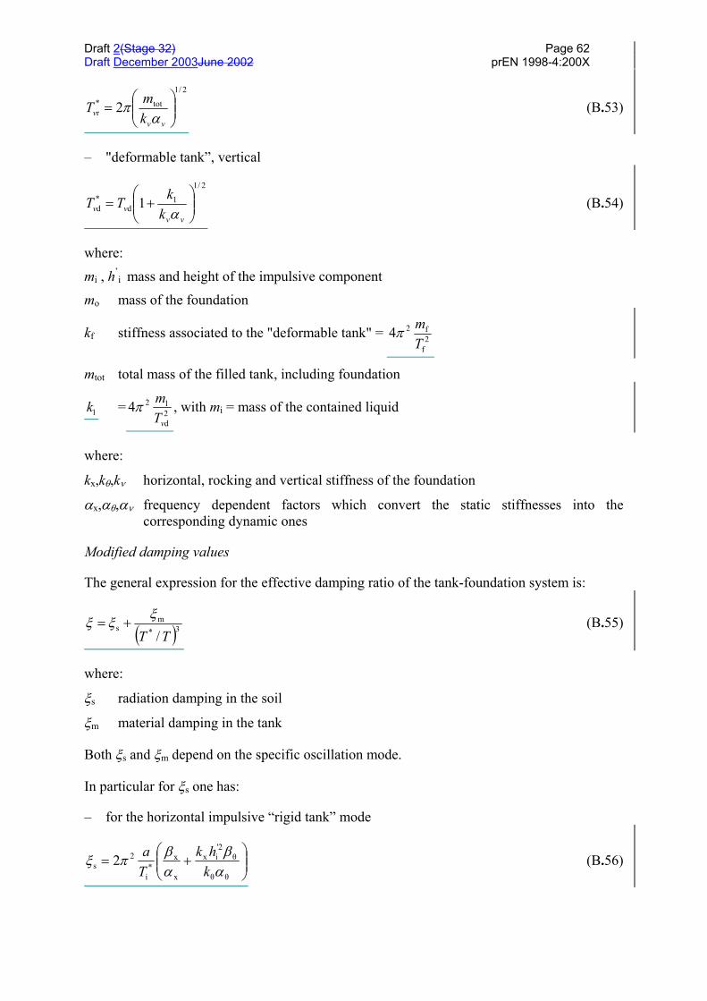
Draft 2(Stage 32) Page 62Draft December 2003June 2002 prEN 1998-4:200X
2/1
tot*r 2
=
vvv k
mTα
π (B.53)
– "deformable tank”, vertical
2/1
1d
*d 1
+=
vvvv k
kTTα
(B.54)
where:
mi , h’i mass and height of the impulsive component
mo mass of the foundation
kf stiffness associated to the "deformable tank" = 2f
f24Tmπ
mtot total mass of the filled tank, including foundation
k1 = 2d
l24vT
mπ , with mi = mass of the contained liquid
where:
kx,kθ,kν horizontal, rocking and vertical stiffness of the foundation
αx,αθ,αν frequency dependent factors which convert the static stiffnesses into thecorresponding dynamic ones
Modified damping values
The general expression for the effective damping ratio of the tank-foundation system is:
( )3*m
s/TT
ξξξ += (B.55)
where:
ξs radiation damping in the soil
ξm material damping in the tank
Both ξs and ξm depend on the specific oscillation mode.
In particular for ξs one has:
– for the horizontal impulsive “rigid tank” mode
+=
θθ
θ'2ix
x
x*
i
2s 2
αβ
αβπξ
khk
Ta (B.56)
Draft 2(Stage 32) Page 63Draft December 2003June 2002 prEN 1998-4:200X
– for the horizontal impulsive “deformable tank” mode
+=
θθ
θ2fx
x
x2*
fx
f2
s2
αβ
αβπξ
khka
Tkm (B.57)
– for the vertical “rigid tank” mode
v
v
vTa
αβπξ *
r
2s 2= (B.58)
where:
a dimensionless frequency function = TVR
s
2π (Vs = shear wave velocity of the soil)
β β βθx v, , frequency-dependent factors providing radiation damping values for horizontal
vertical and rocking motions
Expressions for the factors α α αθx v, , and β β βθx v, , can be found for example in ref.[4].
B.8 Unanchored tanks
Tanks are often built with the walls not anchored to the foundation, for reasons of economy.In case of earthquake, if the overturning moment due to the hydrodynamic forces is largerthan the stabilizing one some uplift occurs. It is difficult to avoid in this case plasticdeformations in the tank, at least in the base plate. Leakage of the liquid, however, can beprevented by proper design.
The mechanism of tank uplift is obviously complex and substantcially sensitive to severalparameters, both from the point of view of tank response and of the subsequent stressanalysis.
In most cases, the effects of the uplift, and of the accompanying rocking motion, on themagnitude and the distribution of the pressures is disregarded, and the pressures calculated foran anchored tank are used. This is believed to be in many a conservative approach, due to thefact that rocking adds flexibility to the tank-fluid system, and hence shifts the period into arange of lesser amplification. This approach is accepted in ref. [5].
The only approximate design procedure elaborated thus far which accounts for the dynamicnature of the problem is presented in ref. [3], and can be used if deemed appropriate.
For the purpose of the present Annex a conceptual outline of the procedure in ref. [3] isadequate.
– The sloshing and the rigid impulsive pressure components are assumed to remainunaffected by the rocking motion.
– The flexible impulsive component is treated using expressions analogous to eq. (B.18) to(B.28), but on the basis of a first mode shape which includes, in addition to thedeformation of the shell, the uplift of the base. Modified values of the mass mf and of its
Draft 2(Stage 32) Page 64Draft December 2003June 2002 prEN 1998-4:200X
height hf are obtained, as functions, as before, of the ratio H/R; of course these modifiedvalues depend on the amount of uplift, but this dependence is found numerically to beweak so that average values can be used.
– For what concerns the dynamic response, the objective is to find the fundamental periodof a system made up of a deformable tank-fluid sub-system, linked to the ground bymeans of vertical springs characterized by a non-linear force-uplift relationship.
– The non-linearity of the base springs is treated in an "equivalent" linear way by assumingtheir average stiffness for a vertical deformation going from zero to the maximum valuereached during the response. Based on extensive Finite Element analyses on steel tankstypical of oil industry, results have been obtained in the form of graphs, which give thefundamental period of the whole system in the form:
=
RH
RdF
gRT ,2 max
f π (B.59)
where dmax is the maximum displacement at the level hf where the mass mf is located, and F(⋅)is an empirical function of the two nonadimensional parameters indicated.
The procedure then works iteratively as follows:
– starting with the fixed-base value of the overturning moment, a value of dmax is obtainedusing a non-dimensional graph prepared for different H/R values;
– based on this value, the period of the system is calculated from eq. (B.59), and using theappropriate response spectrum, the impulsive flexible component of the response isobtained;
– combining the latter response with the sloshing and the rigid-one, a new value of the totaloverturning moment is obtained, and so forth until convergence is achieved.
The limitation in the use of the procedure described is that available design charts refer tospecific values of important parameters, as for ex. the thickness ratio of the wall, the soilstiffness, the wall foundation type, etc., which are known to influence the response to asignificant extent.
Once the hydrodynamic pressures are known, whether determined ignoring or consideringoccurrence of uplift, the following step of calculating the stresses in the critical regions of thetank is a matter of structural analysis, an area in which the designer must have a certainfreedom in selecting the level of sophistication of the method he uses, under the condition thatthe less approximate ones must be clearly on the safe side.
For an uplifting tank, an accurate model would necessarily involve a Finite Element methodwith non-linear capabilities, a fact which is still out of common practice. At the other extreme,rather crude methods, not requiring the use of computer, have been developed long ago, andthey are still proposed in current design standards, as for ex. in ref. [10].
These methods have been proven to be unconservative by experiments and by more refinedanalyses and, more generally, to be inadequate for accounting of all the variables entering theproblem.
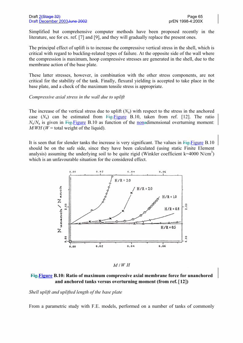
Draft 2(Stage 32) Page 65Draft December 2003June 2002 prEN 1998-4:200X
Simplified but comprehensive computer methods have been proposed recently in theliterature, see for ex. ref. [7] and [9], and they will gradually replace the present ones.
The principal effect of uplift is to increase the compressive vertical stress in the shell, which iscritical with regard to buckling-related types of failure. At the opposite side of the wall wherethe compression is maximum, hoop compressive stresses are generated in the shell, due to themembrane action of the base plate.
These latter stresses, however, in combination with the other stress components, are notcritical for the stability of the tank. Finally, flexural yielding is accepted to take place in thebase plate, and a check of the maximum tensile stress is appropriate.
Compressive axial stress in the wall due to uplift
The increase of the vertical stress due to uplift (Nu) with respect to the stress in the anchoredcase (Na) can be estimated from Fig.Figure B.10, taken from ref. [12]. The ratioNu/Na is given in Fig.Figure B.10 as function of the nonadimensional overturning moment:M/WH (W = total weight of the liquid).
It is seen that for slender tanks the increase is very significant. The values in Fig.Figure B.10should be on the safe side, since they have been calculated (using static Finite Elementanalysis) assuming the underlying soil to be quite rigid (Winkler coefficient k=4000 N/cm3)which is an unfavourable situation for the considered effect.
Fig.Figure B.10: Ratio of maximum compressive axial membrane force for unanchoredand anchored tanks versus overturning moment (from ref. [12])
Shell uplift and uplifted length of the base plate
From a parametric study with F.E. models, performed on a number of tanks of commonly
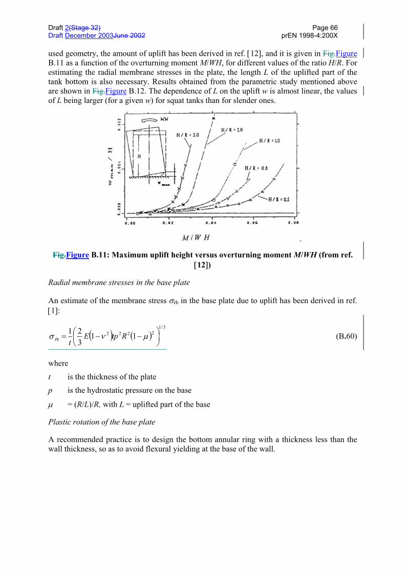
Draft 2(Stage 32) Page 66Draft December 2003June 2002 prEN 1998-4:200X
used geometry, the amount of uplift has been derived in ref. [12], and it is given in Fig.FigureB.11 as a function of the overturning moment M/WH, for different values of the ratio H/R. Forestimating the radial membrane stresses in the plate, the length L of the uplifted part of thetank bottom is also necessary. Results obtained from the parametric study mentioned aboveare shown in Fig.Figure B.12. The dependence of L on the uplift w is almost linear, the valuesof L being larger (for a given w) for squat tanks than for slender ones.
Fig.Figure B.11: Maximum uplift height versus overturning moment M/WH (from ref.[12])
Radial membrane stresses in the base plate
An estimate of the membrane stress σrb in the base plate due to uplift has been derived in ref.[1]:
( ) ( )3/1
2222rb 11
321
−−= µνσ RtpE
t(B.60)
where
t is the thickness of the plate
p is the hydrostatic pressure on the base
µ = (R/L)/R, with L = uplifted part of the base
Plastic rotation of the base plate
A recommended practice is to design the bottom annular ring with a thickness less than thewall thickness, so as to avoid flexural yielding at the base of the wall.

Draft 2(Stage 32) Page 67Draft December 2003June 2002 prEN 1998-4:200X
Fig.Figure B.12: Length of the uplifted part as a function of the uplift (from ref. [12])
The rotation of the plastic hinge in the tank base must be compatible with the availableflexural ductility.
Assuming a maximum allowable steel strain of 0,05 and a length of the plastic hinge equal to2 t, the maximum allowable rotation is.
radians20,022/
05,0=
= t
tθ (B.61)
From Fig.Figure B.13 the rotation associated to an uplift w and a base separation of L is:
−=
Rw
Lw
22θ (B.62)
which must be less than 0,20 radians.
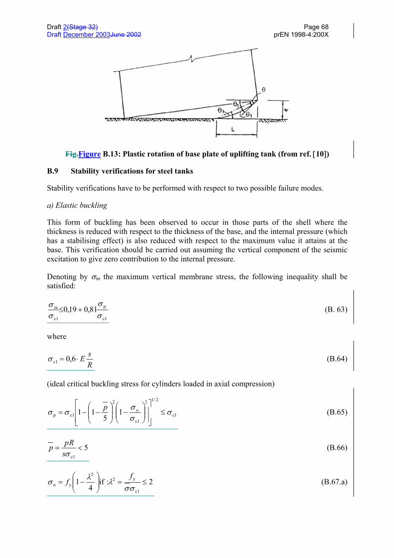
Draft 2(Stage 32) Page 68Draft December 2003June 2002 prEN 1998-4:200X
Fig.Figure B.13: Plastic rotation of base plate of uplifting tank (from ref. [10])
B.9 Stability verifications for steel tanks
Stability verifications have to be performed with respect to two possible failure modes.
a) Elastic buckling
This form of buckling has been observed to occur in those parts of the shell where thethickness is reduced with respect to the thickness of the base, and the internal pressure (whichhas a stabilising effect) is also reduced with respect to the maximum value it attains at thebase. This verification should be carried out assuming the vertical component of the seismicexcitation to give zero contribution to the internal pressure.
Denoting by σm the maximum vertical membrane stress, the following inequality shall besatisfied:
c1
p
c1
m 81,019,0σσ
σσ
+≤ (B. 63)
where
RsE⋅= 6,0c1σ (B.64)
(ideal critical buckling stress for cylinders loaded in axial compression)
c1
2/12
c1
o
2
c1p 15
11 σσσσσ ≤
−
−−=
p (B.65)
5c1
<=σs
Rpp (B.66)
2:if4
1c1
y22
yo ≤=
−=
σσλλσ
ff (B.67.a)
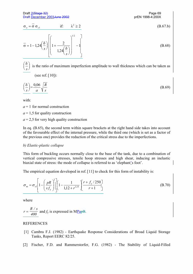
Draft 2(Stage 32) Page 69Draft December 2003June 2002 prEN 1998-4:200X
σ σ σ λo c= ≥12 2if: (B.67.b)
σδ
δ= −
+
−
1 1 1 2
11
1 2
,24,24
/
ss
(B.68)
δs
is the ratio of maximum imperfection amplitude to wall thickness which can be taken as
(see ref. [10]):
δs
= 0,06a
Rs
(B.69)
with:
a = 1 for normal construction
a = 1,5 for quality construction
a = 2,5 for very high quality construction
In eq. (B.65), the second term within square brackets at the right hand side takes into accountof the favourable effect of the internal pressure, while the third one (which is set as a factor ofthe previous one) provides the reduction of the critical stress due to the imperfections.
b) Elastic-plastic collapse
This form of buckling occurs normally close to the base of the tank, due to a combination ofvertical compressive stresses, tensile hoop stresses and high shear, inducing an inelasticbiaxial state of stress: the mode of collapse is referred to as ‘elephant’s foot’.
The empirical equation developed in ref. [11] to check for this form of instability is:
+
+
+
−
−=
1250/
12,1111 y
15,1
2
yc1m r
frrfs
pRσσ (B.70)
where
rR s
=/
400 and fy is expressed in MPapB.
REFERENCES
[1] Cambra F.J. (1982) - Earthquake Response Considerations of Broad Liquid StorageTanks, Report EERC 82/25.
[2] Fischer, F.D. and Rammerstorfer, F.G. (1982) - The Stability of Liquid-Filled

Draft 2(Stage 32) Page 70Draft December 2003June 2002 prEN 1998-4:200X
Cylindrical Shells under Dynamic Loading. Buckling of Shells. E. Ramm (Ed.). Proc. ofthe State-of-the-Art Colloquium, Springer, Berlin, pp. 569-597.
[3] Fischer, F.D.; Rammerstorfer, F.G. and Scharf, K. (1991) - Earthquake ResistantDesign of Anchored and Unanchored Liquid Storage Tanks under Three-dimensionalEarthquake Excitation. Structural Dynamics Recent Advances, Schneller, G.L. (ED).Springer Verlag.
[4] Gazetas, G. (1983) - Analysis of Machine Foundation Vibrations: State-of-the-Art. SoilDynamics and Earthquake Engineering, Vol. 2, n. 1.
[5] Guidelines for the Seismic Design of Oil and Gas Pipeline Systems. ASCE TechnicalCouncil on Lifeline Earthquake Engineering. 1987.
[6] Kim, J.K., Koh, H.M. and Kwack, I.J. (1996) - Dynamic Response of RectangularFlexible Fluid Containers. Journal of Engineering Mechanics, Vol. 122, n. 9, September,pp. 807-817.
[7] Malhotra, P.K. (1995) - Base Uplifting Analysis of Flexibly Supported Liquid-StorageTanks. Earthquake Engineering and Structural Dynamics, Vol. 24, pp. 1591-1607.
[8] Malhotra, P.K. (1997) - Seismic Analysis of Liquid-Storage Steel Tanks. StructuralEngineering International.
[9] Peek, R., Jenning, P.C. (1988) - Simplified Analysis of Unanchored Tanks. EarthquakeEngineering and Structural Dynamics, Vol. 16, pp. 1073-1085
[10] Priestley, M.J.N. (Ed.) (1986) - Seismic Design of Storage Tanks. Recommendations ofa Study Group of the New Zealand National Society for Earthquake Engineering.December.
[11] Rotter, J.M., Seide, P. (1987) - On the Design of Unstiffened Shells Subjected to anAxial Load and Internal Pressure. Prof. of ECCS Colloquium on Stability of Plate andShell Structures, Ghent University, pp. 539-548.
[12] Scharf, K. (1989) - Contribution to the behaviour of Earthquake Excited Above-groundLiquid Storage Tanks. Doctoral Thesis. Institute of Light Weight Structures. Tech. Univ.of ViennB.
[13] Veletsos, B.S. (1977) - Dynamics of Structure - Foundation Systems - Structural andGeotechnical Mechanics. Ed. W.J. Hall, Prentice Hall, Inc., Englewood Cliffs, NewJersey, pp. 333-361.
[14] Veletsos, B.S. and Yu Tang (1987) - Rocking Response of Liquid Storage Tanks.Journal of Engineering Mechanics ASCE, Vol. 113, n. 11, November, pp. 1774-1792.
[15] Veletsos, A.S. and Yu Tang (1990) - Soil-Structure Interaction Effects for LaterallyExcited Liquid Storage Tanks. Earthquake Engineering and Structural Dynamics, Vol.19, pp. 473-496.
[16] Veletsos A.S., Yu Tang, and H.T. Tang (1992) - Dynamic Response of FlexiblySupported Liquid Storage Tanks. Journal of Structural Engineering, ASCE, Vol. 118, n.

Draft 2(Stage 32) Page 71Draft December 2003June 2002 prEN 1998-4:200X
1, January, pp. 264-283.
Draft 2(Stage 32) Page 72Draft December 2003June 2002 prEN 1998-4:200X
ANNEX C (INFORMATIVE) BURIED PIPELINES
C.1 General design considerations
(1) As a rule, pipelines should be laid on soils which are checked to remain stable underthe design seismic action. When the condition above cannot be satisfied, the nature and theextent of the adverse phenomena should be explicitly assessed, and appropriate design countermeasures applied.
(2) Two extreme cases: Soil liquefaction and fault movements are worth being mentioned,since they require in general design solutions specific to each particular case.
(3) Soil liquefaction, whenever it did occur, has been a major contributor to pipelinesdistress in past earthquakes.
(4) Depending on the circumstances, the solution may consist either in increasing theburial depth, possibly also encasing the pipes in larger stiff conduits, or in placing the pipelineabove-ground, supporting it at rather large distances on well founded piers. In the latter caseflexible joints should also be considered to allow for relative displacements between supports.
(5) Design for fault movements requires estimating, sometimes postulating, a number ofparameters including: location, size of the area affected, type and measure of the faultdisplacement. Given these parameters, the simplest way of modelling the phenomenon is toconsider a rigid displacement between the soil masses interfacing at the fault.
(6) The general criterion for minimizing the effect of an imposed displacement is that ofintroducing the maximum flexibility into the system which is subjected to it.
(7) In the case under consideration this can be done:
– by decreasing the burial depth so as to reduce the soil restraint
– by providing a large ditch for the pipes, to be filled with soft material
– by putting the pipeline above ground, and introducing flexible and extensible pipingelements.
C.2 Seismic actions on buried pipelines
(1) The ground motion propagating beneath the soil surface is made up of a mixture ofbody (compression, shear) and surface (Rayleigh, Love, etc) waves, the actual compositiondepending most significantly on the focal depth and on the distance between the focus and thesite.
(2) The various types of waves have different propagation velocities, and differentmotions of the particles (i.e. parallel to the propagation of the wave, orthogonal to it,elliptical, etc.). Although geophysical-seismological studies can provide some insight, theyare generally unable to predict the actual wave pattern, so that conservative assumptions haveto be made.
Draft 2(Stage 32) Page 73Draft December 2003June 2002 prEN 1998-4:200X
(3) One often made assumption is to consider in turn the wave pattern to consist entirelyof a single type of wave, whatever is more unfavourable for a particular effect on the pipeline.
(4) The wave trains can in this case be easily constructed on the basis of the frequencycontent underlying the elastic response spectrum appropriate for the site, by assigning to eachfrequency component an estimated value of the propagation velocity.
(5) Theoretical arguments and a number of numerical simulations indicate that the inertiaforces arising from the interaction between pipe and soil are much smaller than the forcesinduced by the soil deformation: this fact allows to reduce the soil-pipeline interactionproblem to a static one, i.e., one where the pipeline is deformed by the passage of adisplacement wave, without consideration of dynamic effects.
(6) The forces on the pipeline can therefore be obtained by a time-history analysis, wheretime is a parameter whose function is to displace the wave along or across, the structure,which is connected to the soil through radial and longitudinal springs.
(7) A much simpler method is often used, whose accuracy has been proved to becomparable with the more rigorous approach described above, and which yields in any casean upper bound estimate of the strains in the pipeline, since it assumes it to be flexible enoughto follow without slippage nor interaction the deformation of the soil.
(8) According to this method, due to Newmark,6 the soil motion is represented by a singlesinusoidal wave:
)(sin),(cxtωdtxu −= (C.1)
where d is the total displacement amplitude, and c is the apparent wave speed.
(9) The particle motion is assumed in turn to be along the direction of propagation(compression waves), and normal to it (shear waves) and, for simplicity and in order to takethe worst case, the pipeline axis and the direction of propagation coincide.
(10) The longitudinal particle movement produces strains in the soil and in the pipelinegiven by the expression:
)(coscxtω
cdω
xuε −−=
∂∂
= (C.2)
whose maximum value is:
cvε =max (C.3)
with v = ωd being the peak soil velocity
6 Newmark, N. M. 1967, Problems In Wave Propagation In Soil And Rock, Proc. Intnl. Symp. on WavePropagation and Dynamic Properties of Earth Materials, Univ. of New Mexico, Albuquerque, New Mexico, 7-26

Draft 2(Stage 32) Page 74Draft December 2003June 2002 prEN 1998-4:200X
(11) The transverse particle movement produces a curvature χ in the soil and in the pipegiven by the expression:
)(sin2
2
2
2
cxtω
cdω
xuχ −−=
∂
∂= (C.4)
whose maximum value is:
2maxcaχ = (C.5)
with a = ω2d being the peak soil acceleration.
(12) If the directions of the pipeline and of the propagation do not coincide, in both cases ofwave types longitudinal strains and curvatures are produced, which are functioning of theangle ϑθ formed by the two directions. The longitudinal strains are given in this case by
Rθfcaθf
cvθε ⋅+⋅= )( )( )( 221 (C.6)
where R is the diameter of the pipe. Since the second term is in general small compared withthe first one, the maximum of the sum occurs when the first term is at its maximum, that is,with a value: v/c.
(13) For the condition of perfect bond between pipe and soil to be satisfied, the availablefriction force per unit length must equilibrate the variation of the longitudinal force leading to:
2 caEsav =τ (C.7)
where E and s are the Modulus of Elasticity and thickness of the pipe, and τav is the averageshear stress between pipe and soil which depends on the friction coefficient between soil andpipe, and on the burial depth.