
DOCTORAT DE L'UNIVERSITÉ DE TOULOUSEoatao.univ-toulouse.fr/18732/1/MSIRDI.pdf · En vue de...
225
En vue de l'obtention du DOCTORAT DE L'UNIVERSITÉ DE TOULOUSE Délivré par : Institut National Polytechnique de Toulouse (INP Toulouse) Discipline ou spécialité : Sureté de Logiciel et Calcul à Haute Performance Présentée et soutenue par : Mme SOUKAYNA RAJA MSIRDI le mercredi 5 juillet 2017 Titre : Unité de recherche : Ecole doctorale : Modular Avionics Software Integration on Multi-Core COTS: Certification- Compliant Methodology and Timing Analysis Metrics for Legacy Software Reuse in Modern Aerospace Systems Mathématiques, Informatique, Télécommunications de Toulouse (MITT) Institut de Recherche en Informatique de Toulouse (I.R.I.T.) Directeur(s) de Thèse : M. YAMINE AIT AMEUR M. MARC PANTEL Rapporteurs : Mme ISABELLE PUAUT, UNIVERSITE RENNES 1 M. PASCAL RICHARD, ENSMA POITIERS Membre(s) du jury : Mme CHRISTINE ROCHANGE, UNIVERSITE TOULOUSE 3, Président M. FREDERIC BONIOL, ONERA TOULOUSE, Membre M. MARC PANTEL, INP TOULOUSE, Membre Mme CLAIRE MAIZA, UNIVERSITE GRENOBLE ALPES, Membre M. SEBASTIAN ALTMEYER, UNIVERSITE D'AMSTERDAM, Membre
Transcript of DOCTORAT DE L'UNIVERSITÉ DE TOULOUSEoatao.univ-toulouse.fr/18732/1/MSIRDI.pdf · En vue de...

En vue de l'obtention du
DOCTORAT DE L'UNIVERSITÉ DE TOULOUSEDélivré par :
Institut National Polytechnique de Toulouse (INP Toulouse)Discipline ou spécialité :
Sureté de Logiciel et Calcul à Haute Performance
Présentée et soutenue par :Mme SOUKAYNA RAJA MSIRDI
le mercredi 5 juillet 2017
Titre :
Unité de recherche :
Ecole doctorale :
Modular Avionics Software Integration on Multi-Core COTS: Certification-Compliant Methodology and Timing Analysis Metrics for Legacy Software
Reuse in Modern Aerospace Systems
Mathématiques, Informatique, Télécommunications de Toulouse (MITT)
Institut de Recherche en Informatique de Toulouse (I.R.I.T.)Directeur(s) de Thèse :M. YAMINE AIT AMEUR
M. MARC PANTEL
Rapporteurs :Mme ISABELLE PUAUT, UNIVERSITE RENNES 1
M. PASCAL RICHARD, ENSMA POITIERS
Membre(s) du jury :Mme CHRISTINE ROCHANGE, UNIVERSITE TOULOUSE 3, Président
M. FREDERIC BONIOL, ONERA TOULOUSE, MembreM. MARC PANTEL, INP TOULOUSE, Membre
Mme CLAIRE MAIZA, UNIVERSITE GRENOBLE ALPES, MembreM. SEBASTIAN ALTMEYER, UNIVERSITE D'AMSTERDAM, Membre

2

”Liberee, delivreeeeeee...” – Elsa, La Reine des Neiges
”Let it go, let it gooooo” – Elsa, Frozen
1

2

Contents
1 Introduction 491.1 Motivations . . . . . . . . . . . . . . . . . . . . . . . . . . . . . . . . . . . . . . . 491.2 Contributions . . . . . . . . . . . . . . . . . . . . . . . . . . . . . . . . . . . . . . 521.3 Thesis Outline . . . . . . . . . . . . . . . . . . . . . . . . . . . . . . . . . . . . . 56
2 Background 572.1 Terminology . . . . . . . . . . . . . . . . . . . . . . . . . . . . . . . . . . . . . . . 572.2 IMA Systems in the Aerospace Industry . . . . . . . . . . . . . . . . . . . . . . . 592.3 Safety and Certification Regulations . . . . . . . . . . . . . . . . . . . . . . . . . 622.4 WCET Analysis . . . . . . . . . . . . . . . . . . . . . . . . . . . . . . . . . . . . 642.5 Response Time Analysis . . . . . . . . . . . . . . . . . . . . . . . . . . . . . . . . 682.6 Summary . . . . . . . . . . . . . . . . . . . . . . . . . . . . . . . . . . . . . . . . 72
3 State of the Art 733.1 Overview . . . . . . . . . . . . . . . . . . . . . . . . . . . . . . . . . . . . . . . . 733.2 Execution Models . . . . . . . . . . . . . . . . . . . . . . . . . . . . . . . . . . . . 733.3 Dedicated Designs . . . . . . . . . . . . . . . . . . . . . . . . . . . . . . . . . . . 743.4 Software-Based Resource Access Monitoring Approaches . . . . . . . . . . . . . . 763.5 Mixed Criticality Approaches . . . . . . . . . . . . . . . . . . . . . . . . . . . . . 783.6 Hierarchical Scheduling Considerations . . . . . . . . . . . . . . . . . . . . . . . . 803.7 Multicore Scheduling Approaches . . . . . . . . . . . . . . . . . . . . . . . . . . . 823.8 Non-Intrusive Static Timing Analysis Techniques . . . . . . . . . . . . . . . . . . 833.9 Summary and Conclusions . . . . . . . . . . . . . . . . . . . . . . . . . . . . . . . 85
4 Integration Strategies Overview and System Model 894.1 Assumptions . . . . . . . . . . . . . . . . . . . . . . . . . . . . . . . . . . . . . . 894.2 Proposed Integration Strategies . . . . . . . . . . . . . . . . . . . . . . . . . . . . 93
4.2.1 Brief Overview . . . . . . . . . . . . . . . . . . . . . . . . . . . . . . . . . 934.2.2 One-to-All Integration Strategy . . . . . . . . . . . . . . . . . . . . . . . . 944.2.3 One-to-One Integration Strategy . . . . . . . . . . . . . . . . . . . . . . . 964.2.4 Comparison of the Two Strategies . . . . . . . . . . . . . . . . . . . . . . 97
4.3 Software Architecture Model . . . . . . . . . . . . . . . . . . . . . . . . . . . . . 994.4 Hardware Architecture Model . . . . . . . . . . . . . . . . . . . . . . . . . . . . . 1114.5 Constraint Programming . . . . . . . . . . . . . . . . . . . . . . . . . . . . . . . . 116
4.5.1 Allocation Constraints . . . . . . . . . . . . . . . . . . . . . . . . . . . . . 1174.5.2 Scheduling Constraints . . . . . . . . . . . . . . . . . . . . . . . . . . . . . 1184.5.3 Why Constraint Programming . . . . . . . . . . . . . . . . . . . . . . . . 119
4.6 Discussions . . . . . . . . . . . . . . . . . . . . . . . . . . . . . . . . . . . . . . . 1194.7 Summary . . . . . . . . . . . . . . . . . . . . . . . . . . . . . . . . . . . . . . . . 122
3
5 Multicore Timing Analyses 1235.1 Tasks WCRTs and WCETs Computation . . . . . . . . . . . . . . . . . . . . . . 123
5.1.1 Tasks WCRTs and Allocation . . . . . . . . . . . . . . . . . . . . . . . . . 1235.1.2 Task Instances WCETs and Schedule Generation . . . . . . . . . . . . . . 126
5.2 Multicore Interference Computation . . . . . . . . . . . . . . . . . . . . . . . . . 1295.3 Partitions CPU Time Budgets Computation . . . . . . . . . . . . . . . . . . . . . 1385.4 Allocation and Timing-Related Verification . . . . . . . . . . . . . . . . . . . . . 1405.5 Scheduling and Timing-Related Verification . . . . . . . . . . . . . . . . . . . . . 1435.6 Discussions . . . . . . . . . . . . . . . . . . . . . . . . . . . . . . . . . . . . . . . 1465.7 Summary . . . . . . . . . . . . . . . . . . . . . . . . . . . . . . . . . . . . . . . . 147
6 IMA System Integration 1496.1 One-to-All Integration Strategy . . . . . . . . . . . . . . . . . . . . . . . . . . . . 1496.2 One-to-One Integration Strategy . . . . . . . . . . . . . . . . . . . . . . . . . . . 1636.3 Discussions . . . . . . . . . . . . . . . . . . . . . . . . . . . . . . . . . . . . . . . 1706.4 Summary . . . . . . . . . . . . . . . . . . . . . . . . . . . . . . . . . . . . . . . . 170
7 Evaluation Results 1717.1 Software Case Study Generation . . . . . . . . . . . . . . . . . . . . . . . . . . . 1727.2 Hardware Architecture Representation . . . . . . . . . . . . . . . . . . . . . . . . 1747.3 Validation on a Real Target . . . . . . . . . . . . . . . . . . . . . . . . . . . . . . 1787.4 Theoretical Evaluation . . . . . . . . . . . . . . . . . . . . . . . . . . . . . . . . . 1867.5 Certification Compliance Evaluation . . . . . . . . . . . . . . . . . . . . . . . . . 1927.6 Discussions . . . . . . . . . . . . . . . . . . . . . . . . . . . . . . . . . . . . . . . 1947.7 Summary . . . . . . . . . . . . . . . . . . . . . . . . . . . . . . . . . . . . . . . . 197
8 Summary and Perspectives 1998.1 Summary . . . . . . . . . . . . . . . . . . . . . . . . . . . . . . . . . . . . . . . . 1998.2 Conclusions . . . . . . . . . . . . . . . . . . . . . . . . . . . . . . . . . . . . . . . 2018.3 Future Work . . . . . . . . . . . . . . . . . . . . . . . . . . . . . . . . . . . . . . 206
9 Appendices 2079.1 DRAM Parameters for Interference Computation . . . . . . . . . . . . . . . . . . 208
4
List of Figures
1 Strategie d’Integration ”One-to-All” . . . . . . . . . . . . . . . . . . . . . . . . . 402 Strategie d’Integration ”One-to-One” . . . . . . . . . . . . . . . . . . . . . . . . . 42
2.1 Relations Between Avionics Certification Guidelines Documents [11] . . . . . . . 632.2 Execution Times Distribution for a given Task [169] . . . . . . . . . . . . . . . . 652.3 Classic Task Model [105] . . . . . . . . . . . . . . . . . . . . . . . . . . . . . . . . 662.4 Tasks Defined with Jitters upon First Activation . . . . . . . . . . . . . . . . . . 712.5 Classic Holistic model . . . . . . . . . . . . . . . . . . . . . . . . . . . . . . . . . 71
3.1 Summary of the State of the Art . . . . . . . . . . . . . . . . . . . . . . . . . . . 86
4.1 Overview of the One-to-All Integration Strategy . . . . . . . . . . . . . . . . . . 944.2 Overview of the One-to-One Integration Strategy . . . . . . . . . . . . . . . . . . 964.3 Task Model for the Allocation Problem . . . . . . . . . . . . . . . . . . . . . . . 1014.4 Task Model for the Scheduling Problem . . . . . . . . . . . . . . . . . . . . . . . 1014.5 Example of MAF Schedule Resulting from the One-to-One Integration Strategy . 1044.6 Example of MAF Schedule Resulting from the One-to-All Integration Strategy . 1044.7 System Schedule Generation using each Partition CPU Time Budgets (One-to-All
Integration Strategy) . . . . . . . . . . . . . . . . . . . . . . . . . . . . . . . . . . 1054.8 Representing Messages as Memory Accesses in Tasks Response Times: (4.8a)
when using the classic holistic model versus (4.8b) when using the model proposedin this thesis . . . . . . . . . . . . . . . . . . . . . . . . . . . . . . . . . . . . . . 109
4.9 Multicore Hardware Architecture Model . . . . . . . . . . . . . . . . . . . . . . . 1124.10 Model of Memory Banks . . . . . . . . . . . . . . . . . . . . . . . . . . . . . . . . 1134.11 Example of Memory Path Sharing Scenario . . . . . . . . . . . . . . . . . . . . . 1144.12 Core-Level Path Sharing and Runtime Interference . . . . . . . . . . . . . . . . . 115
5.1 Multicore Architectures . . . . . . . . . . . . . . . . . . . . . . . . . . . . . . . . 130
6.1 Steps of the One-to-All Integration Strategy . . . . . . . . . . . . . . . . . . . . . 1506.2 Steps of the One-to-One Integration Strategy . . . . . . . . . . . . . . . . . . . . 164
7.1 Benchmark Selection Process [9] . . . . . . . . . . . . . . . . . . . . . . . . . . . 1737.2 Block Diagram of the Freescale/NXP QorIQ P4080 Processor [9] . . . . . . . . . 1767.3 Target Configuration . . . . . . . . . . . . . . . . . . . . . . . . . . . . . . . . . . 1797.4 Schedule Resulting from Applying the One-to-One Integration Strategy to Inte-
grate the SW Case Study on Five Cores of the P4080 . . . . . . . . . . . . . . . 1807.5 Schedule Resulting from Applying the One-to-All Integration Strategy to Inte-
grate the SW Case Study on Five Cores of the P4080 . . . . . . . . . . . . . . . 1817.6 Parallel Execution of Non-Interfering Tasks . . . . . . . . . . . . . . . . . . . . . 1817.7 Comparison of the Observed Difference between Computed WCETs and the Re-
spective Maximum Measured ETs in each Strategy . . . . . . . . . . . . . . . . . 1827.8 Average Difference between Computed WCETs and Measured WCETs in the
One-to-All Strategy . . . . . . . . . . . . . . . . . . . . . . . . . . . . . . . . . . 183
5
7.9 Average Difference between Computed WCETs and Measured WCETs in theOne-to-One Strategy . . . . . . . . . . . . . . . . . . . . . . . . . . . . . . . . . . 183
7.10 Pessimism Percentage due to the Timing Analysis Independently from the Pes-simism resulting from the Preliminary – Single-Core – Analysis . . . . . . . . . . 184
7.11 Parallel Execution of Non-Interfering Tasks . . . . . . . . . . . . . . . . . . . . . 1867.12 Workload Evolution with the Number of Cores (%) . . . . . . . . . . . . . . . . . 1887.13 Achieved Workload Optimization compared to the Classic Integration Strategy (%)1897.14 Evolution of the Number of Variables and Constraints for the Allocation Search . 1917.15 Evolution of the Number of Variables and Constraints for the Schedule Generation192
6
List of Tables
2.1 Design Assurance Levels (DALs) as Defined in [10, 11, 139, 140] . . . . . . . . . 64
4.1 Comparison of the two Proposed Integration Strategies . . . . . . . . . . . . . . . 97
7.1 Data used for the Software Case Study . . . . . . . . . . . . . . . . . . . . . . . . 1757.2 L1 Cache Model (Identical for both Data and Instruction L1 Caches) . . . . . . . 1777.3 Data used for the Main Memory Model . . . . . . . . . . . . . . . . . . . . . . . 177
9.1 Standard DRAM Parameters . . . . . . . . . . . . . . . . . . . . . . . . . . . . . 209
7

8

”The greatest enemy of knowledge is not ignorance, it is the illusion of knowledge” – StephenHawking
9

10
Acknowledgments
Creating a PhD contract is no piece of cake. It involves submitting an idea to the hierarchy,writing a subject and carefully choosing an academic environment that is relevant to the PhD.For me, it meant coming to a new city, and sacrificing personal paths that were laid out in frontof me to shape my future. When starting a PhD involves such sacrifices, you better make yourPhD worth it to compensate the personal pain by great work and professional perspectives.
This PhD has been the best, but also the worst thing that has happened to me so far. I evencontracted serious back problems during that same period, which lightened once the PhD wasover. I always thought the PhD would be the last guided, schooling environment before enteringthe workforce and all the challenges it brings. I was wrong. But I needed it. These three yearsof PhD have been a mix of technical research, social conventions learning, a bit of politics anddiplomacy sensitization, along with psychological analysis of all the kinds of personalities thatmay exist in the world. I started as a weak student, lacking confidence, way too naive andgullible. I came out of it focused and more efficient, always true to myself and others.
I would like to thank Yamine Ait Ameur for agreeing to be the PhD director.I would like to thank Wenceslas Godard for taking me as a 6-month intern, and then offering
me the position for this PhD contract, which he initiated. Thank you for letting me write thePhD subject. Thank you for all the space and autonomy you have given me, and for alwaysletting me decide what to do and how to react when my work was challenged. It allowed meto stay focused and find my way out of the biggest challenges encountered, would it be abouttechnical difficulties, but also political, socially tough situations. You thus helped shape my owncontributions but also my own character along the way.
I would like to thank Marc Pantel for saying yes to the proposition of Wenceslas of beingthe academic environment for this PhD, although Marc admitted later that the PhD was not inhis field of study. Thank you for giving me enough autonomy to find information and contactrelevant people myself. Thank you for your peculiar sense of humor too, including duringmeetings where you would make funny statements and propose a new challenge to take on everynow and then. I eventually understood that you wanted me to not restrict myself to the solerole of student, but also take the lead, be my own safety net and scope-guard, and only rely onsolid studies to prove my points to you during technical meetings.
Last but not least, I would like to thank both Wenceslas and Marc for offering me the bestgift supervisors could ever offer to their PhD student: the surprise news that you have both beenpushing for my PhD contributions to be reused in a multipartner industrial research project.There is no better proof of you being convinced by my work than such a great news.
Now, I would like to actually thank Stephan Stilkerich for his guidance and support whichtook different shapes over the years, for instance by providing advice on the manuscript break-down, PhD title, etc. but also the industrial contacts that turned out to play an essential rolein the test environment of this thesis. Without you, I would probably not have enough resultsto defend right now.
I would like to thank every contact I had at Absint, Freescale, and Wind River Inc. forhelping me with tools usage and for being interested in my work. Thank you for your patience,especially Stefan Harwarth from Wind River, for always supporting me whenever I asked for an
11
umpteenth free license extension to perform my tests on a real platform.I would like to thank Isabelle Puaut and Pascal Richard for agreeing to review the manuscript
and approve it for defense. I would like to thank Sebastian Altmeyer, Frederic Boniol, ClaireMaiza and Christine Rochange as well for agreeing to be part of my jury and for the rewardingappreciation they delivered at the end of the defense. Special thank you to Stephan Stilkerichagain, who could not make it for the defense and sacrificed himself off the jury so that I coulddefend in July rather than having to find a time slot matching every jury member in September,which can be very complex when it involves professors.
I would like to thank my friends from Paris for supporting me despite the distance. I wouldalso like to thank all the friends I made during conferences and kept in touch with. I amgrateful for your support, your advice but also all the fun we had after the lecture sessions of theconferences. I would also like to thank the PhD students with whom I briefly shared an officein the first year of my PhD, and in general other students and fellow researchers with which Ishared some inspirational talks over a coffee.
I cannot thank enough everyone at Airbus Operations who accepted to join for questioningsessions from time to time, and provided me with all the information I needed to shape mycontributions until it fit their industrial environment. I owe you the relevance of my PhDcontributions.
In the same line of idea I will always remain grateful to Bjorn Lisper for inviting me tojoin the TACLe (Timing Analysis at Code Level) COST Action after I submitted my very firstpaper to a workshop he was chairing. You provided me with the environment I needed to getin touch with the biggest researchers and contributors of the real-time community, but also toattend technical meetings to remain up to date with the state of the art at no cost. This all wasessential in the context of my PhD, and it meant a lot to me. Special thank you to my fatherfor explaining to me what a COST Action was back then, and for encouraging me to join it. Ingeneral thank you to every member of the action with which I had the pleasure to interact with;for your advice, encouragement, but also kindness and the fun we had during conferences.
I would like to thank everyone at Airbus Group Innovations, where I spent almost all my time.Let’s not forget the German side as well, for the team that welcomed me is dispatched betweenFrance and Germany. Thank you to any colleague that got interested in my work, and alwaystook some time to discuss with me whenever they visited Toulouse for some other reason. I willnot state any name by fear of forgetting anyone, but I believe they will recognize themselves. Ingeneral, thank you to every person at Airbus Group Innovations, Airbus Operations and AirbusDefense and Space who accepted to proofread my manuscript sometimes more than once, andwho granted me their friendship; thank you for listening to me and supporting me whenever Itook a hit I was not prepared for, and for always getting me back on my feet.
I would like to thank my several osteopaths for getting me back on my feet too, literally thistime, more than once in three years.
Finally, I would like to thank my family for always supporting me through these hard times.I am still amazed that each and everyone of you made it to the defense, although it was not thatsimple at first. Including little Lilia, aged 7 months when attending my defense; you probablydid not understand much, let alone remember it, but you were a delight to everyone and I verymuch appreciated your presence. Thank you for clearing your busy schedule of kindergartenworkshops and toys reviewing committees, just to come to my defense.
To finish, a special thank you to my mother who took care of everything for the defensecelebration, and who was even more stressed out than me at my defense. And a special thankyou to my father who may even be happier than me over my doctors degree. Thank you forletting me handle everything, and refrain from asking questions even though you quickly sensedthat something was seriously wrong with my PhD environment. I appreciated your patientsupervising, and all the advice you gave me as a professor yourself.
12

13

14

”The best way out is always through” – Robert Frost
15

16
Acronyms
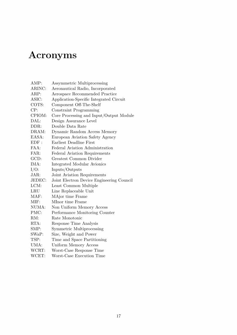
AMP: Assymmetric MultiprocessingARINC: Aeronautical Radio, IncorporatedARP: Aerospace Recommended PracticeASIC: Application-Specific Integrated CircuitCOTS: Component Off-The-ShelfCP: Constraint ProgrammingCPIOM: Core Processing and Input{Output ModuleDAL: Design Assurance LevelDDR: Double Data RateDRAM: Dynamic Random Access MemoryEASA: European Aviation Safety AgencyEDF : Earliest Deadline FirstFAA: Federal Aviation AdministrationFAR: Federal Aviation RequirementsGCD: Greatest Common DividerIMA: Integrated Modular AvionicsI/O: Inputs/OutputsJAR: Joint Aviation RequirementsJEDEC: Joint Electron Device Engineering CouncilLCM: Least Common MultipleLRU Line Replaceable UnitMAF: MAjor time FrameMIF: MInor time FrameNUMA: Non Uniform Memory AccessPMC: Performance Monitoring CounterRM: Rate MonotonicRTA: Response Time AnalysisSMP: Symmetric MultiprocessingSWaP: Size, Weight and PowerTSP: Time and Space PartitioningUMA: Uniform Memory AccessWCRT: Worst-Case Response TimeWCET: Worst-Case Execution Time
17

18

Symbols
19
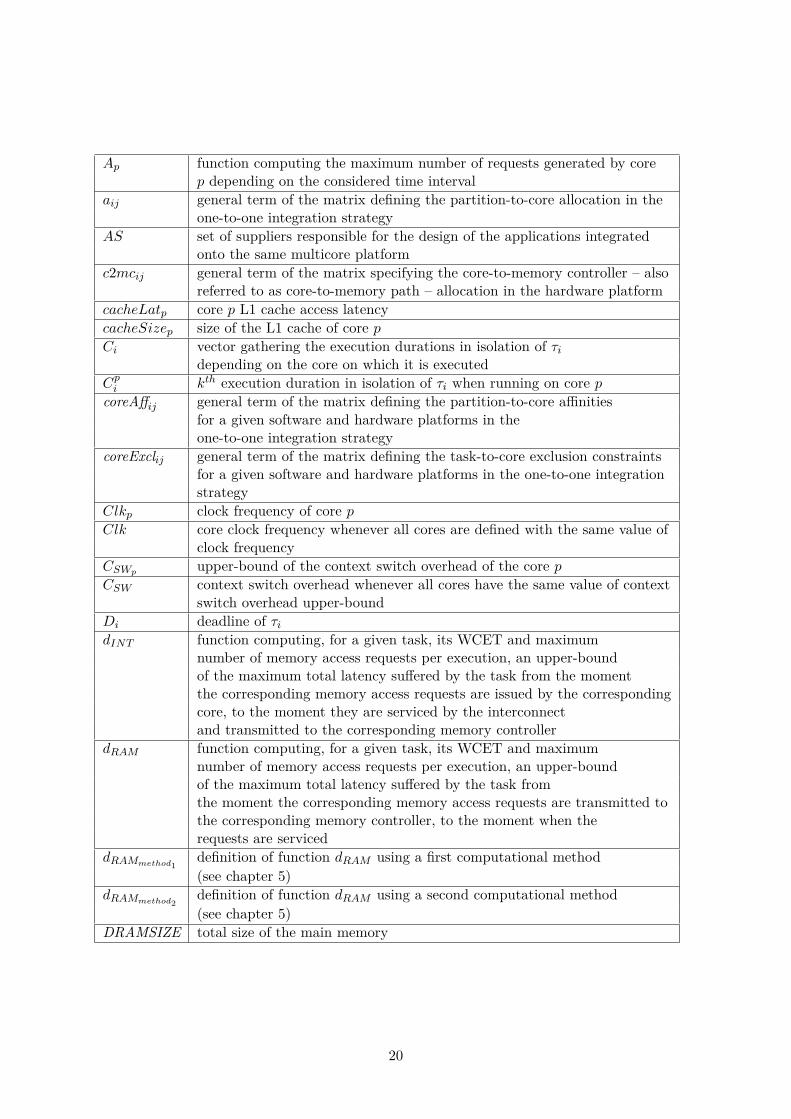
Ap function computing the maximum number of requests generated by corep depending on the considered time interval
aij general term of the matrix defining the partition-to-core allocation in theone-to-one integration strategy
AS set of suppliers responsible for the design of the applications integratedonto the same multicore platform
c2mcij general term of the matrix specifying the core-to-memory controller – alsoreferred to as core-to-memory path – allocation in the hardware platform
cacheLatp core p L1 cache access latencycacheSizep size of the L1 cache of core pCi vector gathering the execution durations in isolation of τi
depending on the core on which it is executedCpi kth execution duration in isolation of τi when running on core pcoreAffij general term of the matrix defining the partition-to-core affinities
for a given software and hardware platforms in theone-to-one integration strategy
coreExclij general term of the matrix defining the task-to-core exclusion constraintsfor a given software and hardware platforms in the one-to-one integrationstrategy
Clkp clock frequency of core pClk core clock frequency whenever all cores are defined with the same value of
clock frequencyCSWp upper-bound of the context switch overhead of the core pCSW context switch overhead whenever all cores have the same value of context
switch overhead upper-boundDi deadline of τidINT function computing, for a given task, its WCET and maximum
number of memory access requests per execution, an upper-boundof the maximum total latency suffered by the task from the momentthe corresponding memory access requests are issued by the correspondingcore, to the moment they are serviced by the interconnectand transmitted to the corresponding memory controller
dRAM function computing, for a given task, its WCET and maximumnumber of memory access requests per execution, an upper-boundof the maximum total latency suffered by the task fromthe moment the corresponding memory access requests are transmitted tothe corresponding memory controller, to the moment when therequests are serviced
dRAMmethod1definition of function dRAM using a first computational method(see chapter 5)
dRAMmethod2definition of function dRAM using a second computational method(see chapter 5)
DRAMSIZE total size of the main memory
20
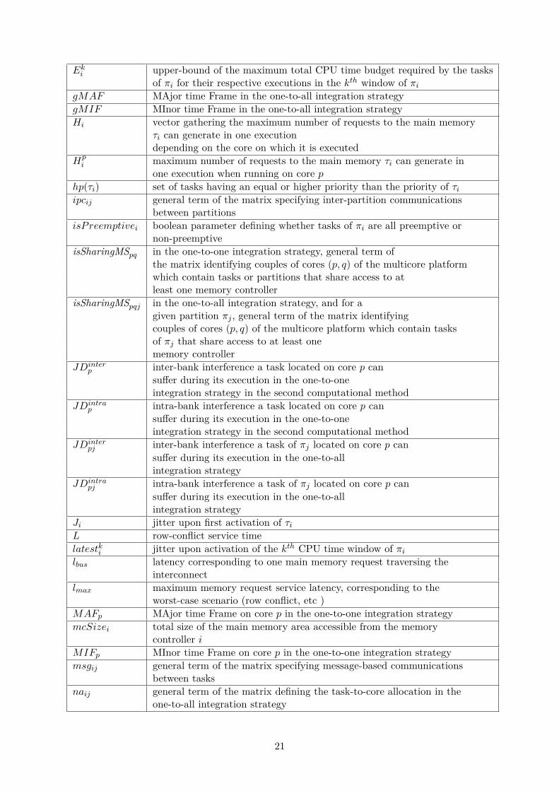
Eki upper-bound of the maximum total CPU time budget required by the tasksof πi for their respective executions in the kth window of πi
gMAF MAjor time Frame in the one-to-all integration strategygMIF MInor time Frame in the one-to-all integration strategyHi vector gathering the maximum number of requests to the main memory
τi can generate in one executiondepending on the core on which it is executed
Hpi maximum number of requests to the main memory τi can generate in
one execution when running on core phppτiq set of tasks having an equal or higher priority than the priority of τiipcij general term of the matrix specifying inter-partition communications
between partitionsisPreemptivei boolean parameter defining whether tasks of πi are all preemptive or
non-preemptiveisSharingMSpq in the one-to-one integration strategy, general term of
the matrix identifying couples of cores pp, qq of the multicore platformwhich contain tasks or partitions that share access to atleast one memory controller
isSharingMSpqj in the one-to-all integration strategy, and for agiven partition πj , general term of the matrix identifyingcouples of cores pp, qq of the multicore platform which contain tasksof πj that share access to at least onememory controller
JDinterp inter-bank interference a task located on core p can
suffer during its execution in the one-to-oneintegration strategy in the second computational method
JDintrap intra-bank interference a task located on core p can
suffer during its execution in the one-to-oneintegration strategy in the second computational method
JDinterpj inter-bank interference a task of πj located on core p can
suffer during its execution in the one-to-allintegration strategy
JDintrapj intra-bank interference a task of πj located on core p can
suffer during its execution in the one-to-allintegration strategy
Ji jitter upon first activation of τiL row-conflict service timelatestki jitter upon activation of the kth CPU time window of πilbus latency corresponding to one main memory request traversing the
interconnectlmax maximum memory request service latency, corresponding to the
worst-case scenario (row conflict, etc )MAFp MAjor time Frame on core p in the one-to-one integration strategymcSizei total size of the main memory area accessible from the memory
controller iMIFp MInor time Frame on core p in the one-to-one integration strategymsgij general term of the matrix specifying message-based communications
between tasksnaij general term of the matrix defining the task-to-core allocation in the
one-to-all integration strategy
21

nbActivi total number of executions of τi in one MAF
nbCacheLinesp number of cache lines of the L1 cache of core pnbWindowsi total number of CPU time windows reserved for πi in one MAFNC number of cores available on the multicore platform and considered
for active usage at runtimenFramesi total number of frames in the partition cycle of πinFrames total number of frames in the MAFNMC total number of memory controllers – also referred to as memory
paths – available in the hardware platformNT total number of tasks integrated onto the same multicore platformNTasa total number of tasks developed by supplier asaNP total number of partitions integrated onto the same multicore platformNPasa total number of partitions developed by supplier asaoverlappingijkl general term of the matrix identifying couples of task instances
pτki , τljq scheduled at least partially in parallel on different cores
of the multicore platformp2mcij general term of the matrix defining the partition-to-memory
controller – also referred to as partition-to-memory path – inthe one-to-one integration strategy
Pasa set of partitions of all applications integrated onto the samemulticore platform
PARTij general term of the matrix defining the task-to-partition allocationπi ith partition of the software platform, i e partition which identifier is iPi period of repetition of πipidi identifier of the partition to which τi belongspOki start date of the kth time window of πipPrecij general term of the matrix specifying inter-partition
precedence relations and/or partitions ordering preferences of systemdesigners and integrators to be enforced in the partition-level schedule
pRampi size of memory space reserved for πi in the main memory area
accessible from the pth memory controllerprecij general term of the matrix specifying inter-task precedence relationsprioi priority of τiRi worst-case response time (WCRT) of τi computed during the
schedulability analysisRki WCRT of τkiRDinter
p inter-bank interference a task located on core p can suffer duringits execution in the one-to-one integration strategyin the first computational method
RDintrap intra-bank interference a task located on core p can suffer during
its execution in the one-to-one integration strategyin the first computational method
RDinterpj inter-bank interference a task of πj located on core p can suffer during
its execution in the one-to-all integration strategyin the first computational method
RDintrapj intra-bank interference a task of πj located on core p can suffer during
its execution in the one-to-one integration strategyin the first computational method
22

reorder delay suffered by a memory request due to the reordering effectsharedpq general term of the matrix defining whether cores p and q share
access to some main memory area in the one-to-one integrationstrategy
sharedpqj general term of the matrix defining whether, for a given partitionπj , cores p and q schedule tasks of πj that share access tosome main memory area in the one-to-all integration strategy
t2mcij general term of the matrix defining the task-to-memory controller – alsoreferred to as task-to-memory path – in the one-to-all integrationstrategy
τi ith task of the considered task set, i e task which identifier is iτki kth execution instance of τiT set of tasks of all applications integrated onto the same multicore
platformT asa set of tasks of all applications designed by supplier asaTi period of repetition of τitaskCoreAffij general term of the matrix defining the task-to-core affinities for a
given software and hardware platforms in the one-to-allintegration strategy
taskCoreExclij general term of the matrix defining the task-to-core exclusionconstraints for a given software and hardware platforms in theone-to-all integration strategy
tOki start date of the execution of τkitRami memory footprint of τiui utilization ratio of τi, also referred to as workload of τiwi worst-case execution time (WCET) of τiwki WCET of τkiW ptq workload of a processing resource in a time interval r0, tr
23

24

Resume
Les contentions apparaissant au niveau des ressources partagees par les coeurs d’un multicoeursont problematiques pour les systemes temps reel critiques. C’est en particulier le cas pourl’industrie aerospatiale, ou il est imperatif d’assurer un comportement temporel sain de toutsysteme, et ce en avance de phase dans le cycle de developpement. Etre capable de predire lerespect de toutes les echeances temporelles d’un systeme dans n’importe quelle situation pouvantetre rencontree en temps-reel dans l’environnement du systeme sous etude est indispensable pourobtenir les accreditations delivrees par les autorites de certification au niveau logiciel.
Le but de cette these est de proposer une approche pour le portage d’applications IMA(Avionique Modulaire Integree) preexistantes sur plateforme multicoeur, et ce sans modificationmajeure tant au niveau logiciel que materiel. L’objectif final de la these est de proposer uneapproche qui respecte les objectifs de certification appliques au developpement de calculateurslogiciels; cela implique aussi bien les contraintes de certification incrementale, que le respect desconcepts cles de l’IMA, a savoir le partitionnement spatial et temporel des applications integreessur le meme module multicoeur.
Cette these intervient dans le cadre d’un contrat CIFRE (Contrat de d’Initiation a la Forma-tion a la Recherche en Entreprise), a la demande d’Airbus Group Innovations Toulouse. Ainsi,une volonte additionnelle aux objectifs de la these et d’importance majeure est celle de suivre leplus possible les process intervenant dans les cycles de developpement de logiciel IMA tels qu’ilsexistent aujourd’hui chez Airbus, pour des calculateurs bases single-core. Si l’on propose unemethodologie d’integration multicoeur qui possede un maximum de similitudes avec le processd’integration actuelle, cela augmente les chances des contributions de cette these d’etre exploitesen entreprise dans les plus brefs delais, l’effort a fournir pour proposer une nouvelle facon detravailler a des centaines de personnes experimentees et habituees aux process existants depuisun certain nombre d’annees etant generalement significatif. Il est notamment plus facile de con-vaincre des personnes de passer a une nouvelle methodologie si l’effort d’adaptation est moindre,c’est-a-dire si les etapes impliquees dans la nouvelle methodologie ne sont pas tres differents decelles dans l’ancienne methodologie. De plus, l’efficacite de la nouvelle approche est plus facilea prouver si l’approche ressemble aux process actuels, dont l’efficacite pour obtenir l’accord desautorites de certification n’etant en general plus a prouver.
Enfin, un objectif secondaire de la these est de chercher a optimiser au maximum les ar-chitectures integrees resultant de l’etape d’integration logicielle/materielle. Si possible, une ouplusieurs des etapes de la methodologie d’integration multicoeur devraient etre automatisees,de maniere a accelerer les etudes de choix d’architecture tout en orientant la selection finalevers des conceptions optimisant les criteres de performance les plus pertinents pour l’industrieaerospatiale. L’automatisation permet egalement la reduction du temps et effort a fournir pourles tests et verifications impliques dans le cycle d’integration, et ainsi de reduire le time-to-market du systeme avionique complet.
Cette these propose deux methodologies completes pour l’integration IMA sur COTS (Com-ponent Off the Shelf, ou composant sur etagere) multicoeur. Toutes deux offrent des avan-tages differents et s’utilisent dans des situations complementaires. Au final, il s’averera que lesmethodologies proposees depassent le cadre fixe originellement dans cette these: elle peuvents’utiliser dans le cadre de developpement de nouveau logiciel, qu’il soit IMA ou non, tant que
25
l’architecture visee est basee sur des multicoeurs.L’une des deux methodologies, appelee ”one-to-all integration strategy”, correspond a la sit-
uation ou, a un instant donne, tous les coeurs sont utilises au service d’une seule et meme parti-tion. Cette strategie respecte tous les objectifs de certification, y compris le developpement, laverification et certification incrementale, mais aussi le partitionnement robuste (spatio-temporel)des applications. La strategie ”one-to-one” reste pertinente pour tous les niveaux de criticitelogicielle, y compris pour les applications DAL A (le plus haut niveau de criticite). Pour cesraisons, la strategie ”one-to-one” peut etre vue comme la strategie ayant le plus de chance d’etreexploitee par l’industrie aerospatiale a l’issue de cette these.
La seconde strategie, nommee ”one-to-one integration strategy” correspond a la situationou chaque coeur du multicoeur a son propre schedule et ordonnance son lot de partitionsindependamment. Elle peut etre utilisee pour des applications IMA jusqu’au niveau de crit-icite DAL C, pour une application multipartitions jusqu’au DAL A, ou encore pour tout logicieltemps-reel critique non IMA.
Les deux methodologies d’integration proposees sont qualifiees de ”completes” car elles con-tiennent:
• Une analyse temporelle statique qui borne les interferences inter-coeurs et permet dederiver des bornes superieures de WCETs de maniere fiable;
• Une formulation de probleme de programmation par contraintes (PPC) pour l’allocationautomatique et optimisee de logiciel sur materiel; la configuration resultante est correctepar construction car le probleme de PPC exprime exploite l’analyse temporelle mentionneeprecedemment pour effectuer une verification temporelle sur chaque configuration testee.
• Une formulation de probleme de PPC pour la generation d’ordonnancement automatique etoptimise; la configuration resultante est correcte par construction car le processus exploitel’analyse temporelle mentionnee precedemment pour effectuer une verification temporellesur chaque configuration testee.
26
Abstract
Interference in multicores is undesirable for hard real-time systems, especially in the aerospaceindustry for which it is mandatory to ensure beforehand timing correctness and deadline en-forcement in a system runtime behavior, to be granted acceptance by certification authorities.
The goal of this thesis is to propose an approach for multi-core integration of legacy Inte-grated Modular Avionics (IMA) software, without any hardware nor software modification, andwhich complies as much as possible to current, incremental certification and IMA key conceptssuch as robust time and space partitioning. The motivation of this thesis, supported by AirbusGroup Innovations as an industrial PhD contract, is to stick as much as possible to the currentIMA software integration process to maximize the chances of having avionics industries applythe contributions of this thesis to their future systems. Another reason is that the current pro-cess has long been proven efficient on aerospace systems currently in usage. A third motivationis to minimize the extra effort needed to provide certification authorities with timing-relatedverification information required when seeking approval. As a secondary goal, depending on thepossibilities, the contributions should offer design optimization features, and help reduce thetime-to-market by automating some steps of the design and verification process.
This thesis proposes two complete methodologies for IMA integration on multi-core Compo-nents Off The Shelf (COTS). Each of them offers different advantages and has different draw-backs, and therefore each of them may correspond to its own, complementary situations. Oneof the two proposed strategies fits all avionics and certification requirements of incrementalverification and robust partitioning, and can therefore be used for applications with the high-est criticality level, also referred to as Design Assurance Level (DAL) A. The other strategyproposed in this thesis offers maximum Size, Weight and Power (SWaP) optimization, and fitseither up to DAL C applications, multipartition applications or even non-IMA applications.
The methodologies are said to be ”complete” because this thesis provides all necessary tech-niques to go through all steps of the software integration process. More specifically, this includesfor each strategy:
• Static timing analysis metrics for safely upper-bounding inter-core interference, and deriv-ing safe WCET upper-bounds for each task. Both feasibility and schedulability analysisare considered in this thesis for multicore-based IMA systems.
• A Constraint Programming (CP) formulation of the software/hardware allocation problemfor multicore-based IMA systems. Proposing a CP formulation enables the automation ofthe design space exploration and allocation configuration. The allocation selected at theend of the CP solving process is correct by construction since the CP problem embracesone of the proposed timing analysis mentioned earlier.
• A CP formulation of the schedule generation for multicore-based IMA systems. As forthe allocation, proposing a CP formulation enables the automation of the design spaceexploration and schedule generation process. The schedule generated at the end of the CPsolving process is correct by construction since the CP problem embraces the proposedtiming analysis mentioned earlier.
27

28
Resume Etendu
Motivations
Pour les systemes temps-reel dur, il est tout aussi important d’obtenir des resultats exacts, quede les obtenir a temps. En particulier pour les systemes avioniques, des resultats corrects obtenusen retard, soit apres l’echeance qui a ete defini pour le calcul de ces resultats, peuvent conduirea un dysfonctionnement majeur au niveau du systeme avion complet, avec des consequencesgraves telles que la mort des passagers de l’avion et la perte de l’avion.
Pour que ce genre de situation ne se produise jamais, les systemes avioniques font l’objetd’un cycle de conception et de verification strictement reglemente, couple a un processus decertification strict avant d’etre juges operationnels puis commercialises. Par exemple, en cequi concerne les logiciels critiques embarques dans un systeme avionique, chaque operation delogiciel doit etre analysee au moment du design afin de deriver un majorant superieur des tempsd’execution pire cas (aussi notes WCET, pour Worst Case Execution Time) de chaque traitementdefini dans le logiciel, de maniere a pouvoir verifier la validite des echeances associees, configureren avance de phase le plan d’ordonnancement, i.e. les enchaınements des traitements logicielsdans le temps, et verifier que toutes les echeances seront toujours respectees a l’execution pendanttout le temps de vol de l’avion. Une fois que le resultat d’une telle verification montre le respectde toutes les echeances, le resultat et le processus de verification lui-meme peuvent etre montresaux autorites de certification comme justification d’un comportement temps-reel sain, prouveen avance de phase.
La certification d’un avion est cruciale pour sa commercialisation. Au niveau logiciel,elle implique un respect d’un certain nombre d’objectifs definis par les autorites. Cherchera respecter ces objectifs et le prouver representent une part importante de l’effort de concep-tion et verification dans le cycle de vie d’un logiciel avionique, afin d’assurer sa conformite auxreglementations de certification. Cela s’applique non pas seulement au logiciel, mais a toutsous-systeme constituant l’avion. Chaque fois qu’une modification est effectuee sur une partied’un systeme avionique, toutes les parties de ce systeme qui sont impactees par les modifica-tions doivent etre re-verifiees, et leur conformite a la reglementation de certification a nouveauprouvee.
Une maniere efficace d’essayer de reduire le temps et les efforts passes a gerer des modifica-tions de conception consiste a adopter une approche de conception modulaire et independante.Par exemple, l’ensemble des logiciels integres dans un systeme avionique representent plusieursapplications qui ne sont pas necessairement developpees par le meme fournisseur. D’un autrecote, chaque application est developpee independamment l’une de l’autre, peu importe le four-nisseur, pour des raisons de securite. Cela permet egalement de s’assurer que chaque applicationpeut etre analysee independamment l’une de l’autre, de sorte que la modification d’une fonctionn’ait aucun impact sur les autres fonctions. En tant que tel, seules les fonctions modifiees devrontetre re-verifiees; Le processus de developpement, de verification et de certification permettantce genre d’independance est dit incremental [172].
En plus de la certification incrementale, l’architecture IMA (Avionique Modulaire Integree)[1] favorise la modularite des systemes avioniques. Dans les architectures IMA, une applicationlogicielle est divisee en sous-elements executes strictement independamment les uns des autres
29

a l’execution, ce qui assure une isolation temporelle et spatiale de ces sous-elements entre eux.Une telle separation est souvent appelee partitionnement robuste.
En resume, les concepts de certification incrementale et d’architecture IMA assurent la mod-ularite d’un systeme avionique, et necessitent une strategie de verification qui conserve l’espritde separation et isolation des applications et sous-elements des applications. Chaque fournisseurd’application decide comment decouper une application en sous-elements independants. Pourcette raison, les fournisseurs d’applications discutent avec les concepteurs de l’avion en cours dedeveloppement; la connaissance et l’experience des fournisseurs d’applications et des concepteursde systemes avioniques sont essentielles pour certifier les systemes avioniques.
Tout logiciel est execute sur une plateforme materielle sur laquelle un processeur au moinsest present. En regle general pour des systemes aussi critiques que les systemes aerospatiaux,la tendance est d’exploiter des processeurs sortis sur le marche depuis deja quelques annees,dont les processeurs precedents de la meem famille ont en general un historique d’utilisationdans l’industrie aerospatiale consequent, mais surtout qui sont juges suffisamment fiables pardes concepteurs de systemes experts dans le domaine de l’embarque temps-reel critique.
La motivation principale d’un tel choix est de pouvoir compter sur des plateformes electroniquesqui ont eu le temps d’etre testee de maniere approfondie, et qui se sont averees compatibles avectoutes les exigences des systemes avioniques dans lesquels elles ont ete exploitees. Une autremotivation est de faciliter la conception des futurs systemes avioniques, car il est plus facilede reutiliser une plateforme materielle dont les caracteristiques temps-reel et comportementalessont bien connues par experience du fait de son utilisation dans un programme avion anterieur.
Jusqu’a present, les plateformes materielles embarquees dans les systemes avioniques ne con-tiennent que des processeurs monocoeur. Depuis quelques annees, les processeurs multicoeur– jusqu’a 8 ou 16 coeurs sur une meme puce – et manycore – des centaines de coeurs sur unepuce organisee en plusieurs tuiles et reliees par un reseau sur puce – ont fait leur apparition surle marche de l’electronique. Chaque coeur supplementaire sur une puce permet d’augmenter lenombre d’instructions logicielles traitees a un instant donne, ameliorant ainsi les performancesdu systeme concerne. En l’occurrence, les derniers ordinateurs et telephones mobiles proposesau grand public ont pu beneficier d’un gain de performance significatif en embarquant de tellesarchitectures. Le marche de l’electronique evoluant a une tres grande vitesse, il suffit de six moisdepuis la sortie d’un composant electronique sur le marche pour que celui-ci devienne obsolete.C’est le cas pour les processeurs; en particulier, maintenant que les fondeurs de processeur onttrouve comment integrer plus d’un coeur a une puce de processeur, les architectures monocoeurne vont plus etre poursuivies. Cela constitue un probleme pour l’industrie avionique, dont tousles systemes, les etudes de comportement temporel, l’experience passee, repose sur l’utilisationde processeurs monocoeurs. Les systemes aerospatiaux en general ne representent pas une partde marche assez interessante pour les fabricants de processeurs pour que ces derniers acceptentde poursuivre la production de processeurs monocoeurs exploites dans les systemes avioniques.Par consequent, l’industrie aerospatiale n’a guere d’autre choix que de s’adapter a l’evolutiondu marche electronique, et ainsi de passer a des architectures multi- ou manycoeurs.
Dans la mesure ou le nombre d’applications logicielles, et plus generalement le nombre delignes de code embarquees dans un avion augmente au fil des programmes, l’avenement des multi-manycoeurs peut s’averer benefique pour l’industrie avionique. En effet, une unique plateformemulticoeur pourrait potentiellement remplacer autant de plateformes monocoeurs qu’il n’y ade coeurs dans le multicoeur exploite. Cela permettrait de reduire le poids et volume total del’avion, sans compter le nombre de cables a embarquer pour relier l’ensemble des plateformesembarquees, et le besoin en energie necessaire pour alimenter toutes ces plateformes materiellestout le long de la mise en service de l’avion.
Cependant, passer au multicoeur dans les systemes avioniques souleve un certain nombrede challenges [109]. En particulier, l’ensemble des procedures et standards intervenant dans les
30
differentes phases de developpement d’un calculateur embarque doivent auparavant etre misesa jour car elles sont adaptees aux architectures monocoeur et ne permettent pas de couvrir lescas multicoeurs, ou plus d’un traitement logiciel est execute a chaque instant. En particulier, laverification du bon comportement temporel et la preuve du respect des objectifs de certificationassocies sont plus complexes a mettre en oeuvre. L’utilisation d’un multicoeur dans un avion,avec plus d’un coeur executant des traitements applicatifs a chaque instant, ne sera pas possibletant que ces points ne seront pas regles au prealable.
Un exemple concret de standard devant etre mise a jour pour inclure le cas multicoeurest le standard definissant la maniere dont un logiciel IMA doit s’interfacer avec toute plate-forme materielle sur laquelle il s’executera. En particulier, la mise a jour de ce standard de-vra prendre en consideration l’independance des applications s’executant en simultane sur descoeurs differents, malgre le partage de ressources materielles entre les coeurs d’un meme pro-cesseur. Cela represente un challenge significatif. En effet, en raison des acces simultanesaux ressources partagees a l’interieur de la puce multicœur qui se produisent au moment del’execution, l’isolement temporel est difficile a realiser au moment de l’execution sur une plate-forme multicoeur.
De maniere generale, toutes les activites d’analyse et de verification habituellement meneesdans un cycle de conception de logiciel temps-reel embarque doivent etre mises a jour avecdes outils et des techniques capables d’analyser des plateformes multicœurs. Les interferencesinter-core au moment de l’execution doivent etre majorees en toute securite lors de l’analyse destemps d’execution pire cas des traitements logiciels, afin de pouvoir configurer en toute securiteen avance le comportement d’execution du systeme au moment du design. C’est seulement apresde telles mises a jour que les concepteurs de systemes seraient en mesure d’utiliser correctementles plates-formes multicœurs pour les systemes aerospatiaux, mais aussi de pouvoir petit a petitreconstruire les connaissances et le savoir-faire necessaires pour maıtriser les systemes avioniquesmulticoeurs pour faciliter la reutilisation de plateformes similaires dans les programmes suivants.
L’apparition d’interference inter-coeur a l’execution pose probleme a la verification du com-portement temporel d’un logiciel, principalement en raison du manque actuel d’outils ou detechniques permettant de produire un majorant des WCET de taches executees dans un en-vironement multicoeur [171]. Les demandes simultanees d’acces aux ressources generees parchaque coeur provoquent des delais d’attente d’acces aux ressources qui viennent s’ajouter autemps d’execution du code associe a chaque tache. Ces delais supplementaires augmentent lestemps d’execution des taches de maniere plus ou moins significative suivant le multicoeur etle logiciel considere. Le niveau de complexite de l’analyse a mener d’une part, et le couplagedu partage des ressources dans les multicoeurs d’autre part, sont tels que l’analyse temporelledevient intractable, sinon trop pessimiste lorsqu’on essaie de reutiliser les techniques monocoeuractuelles en modelisant un environnement multicoeur. D’autant plus qu’il est encore impossiblede modeliser une architecture multicoeur avec autant de precision qu’une architecture mono-coeur meme si on parvient a maıtriser la complexite des couplages impliques par l’architecture.En effet, le manque d’information de conception par souci de protection d’IP par les fabricantsde processeur, rendent la tache encore plus delicate. Il ne suffit pas de trouver une techniqued’analyse temporelle multicoeur; il faut aussi pouvoir contourner le manque d’information surcertaines ressources partagees a l’origine de delais d’interference, comme les bus d’interconnexionentre les coeurs et les peripheriques du processeur par exemple.
Aujourd’hui, il n’existe aucune solution pour l’analyse exhaustive de WCET sur multicoeur.Sans une telle solution, les contentions au niveau des ressources partagees ne peuvent pas etremodelisees et majorees de maniere absolue, de sorte qu’il n’y a aucun moyen de configurer al’avance un plan d’ordonnancement dont on puisse apporter la preuve que toutes les echeancesdu systeme seront toujours respectees a l’execution. Un tel manque de techniques d’analysemet en peril l’exploitation de platesformes multicoeur dans les systemes aerospatiaux, ce qui
31

en fait l’un des sujets de recherche les plus etudies, dans le milieu academique mais aussi dansl’industrie aerospatiale et automobile. [90, 129, 119, 66, 64].
La litterature est pleine de diverses propositions pour aborder les problemes poses par lemulticoeur [64]:
• Certains travaux proposent de nouvelles couches middleware pour surveiller tous les accesaux ressources materielles partagees, afin d’imposer des comportements d’execution deterministesen eliminant les interferences inter-core a l’execution [46];
• D’autres travaux proposent de nouvelles architectures multicoeur dediees dans lesquelleschaque coeur possederait ses propres ressources privees [7, 181, 149];
• Des travaux similaires se focalisent sur l’implementation de composants hardware perme-ttant de controler le partage de ressources, en esperant voir ces composants integres auxfutures generations de COTS multicoeurs [111, 130, 170];
• Une toute autre strategie egalement consideree dans la litterature est de proposer unnouveau modele d’execution suivant lequel les phases de calcul pur et les phases d’accesaux ressources partagees sont separees de maniere explicite pour reduire les congestionsdans les multicoeurs [58];
• D’autres travaux proposent de nouvelles techniques d’analyse temporelle pour estimerou majorer les congestions dues au partage de ressource, en se reposant ou non sur desmodifications du logiciel et/ou du materiel constituant le systeme sous etude [19, 67, 85,91, 111, 116, 118, 122, 127, 51].
La presente these a ete initiee et financee par Airbus Group Innovations Toulouse, en tantque CIFRE (Contrat d’Initiation et Formation a la Recherche en Entreprise) en partenariat avecle laboratoire IRIT de Toulouse. L’objectif principal de la these est de proposer une approchepour la reutilisation d’applications IMA legacy (preexistantes) sur des processeurs multicœurs,sans modification materielle ou logicielle.
La motivation principale de cette these est de maintenir autant que possible les processusindustriels actuels, afin de maximiser les chances d’acceptation des contributions proposees parles industries aerospatiales et les autorites de certification en minimisant les changements etl’effort d’adaptation qui seraient necessaires pour exploiter les contributions de these dans uncadre industriel.
Un objectif secondaire de cette these est d’automatiser et optimiser un maximum les etapeset sorties des phases conception logicielle, de maniere a tirer profit du gain de performance queles mutlcioeurs peuvent potentiellement apporter.
Pour finir, la liste suivante regroupe les contraintes fortes imposees comme cadre de cettethese, qui ont ete idnetifiees lors des premiers mois de these comme lignes directrices des contri-butions, afin d’augmenter leurs chances d’etre consideree comme une solution pour la prochainegeneration de systemes aerospatiaux:
• Les contributions proposees doivent etre applicables a tout niveau de criticite, en particulieraux applications IMA de DAL A. En effet, comme nous l’avons deja mentionne brievement,toute tentative de solution proposee dans la litterature a ce jour n’est soit pas applicableaux systemes IMA, soit necessite une quantite importante de modifications et d’effortspour etre utilisee pour les systemes IMA. De plus, aucune solution visant les systemesIMA ne couvre l’ensemble des defis entravant l’utilisation de multicoeurs dans les systemesavioniques.
• Les contributions proposees ne devraient pas etre specifiques a une plate-forme materielleparticuliere ni s’appuyer sur uentechnologie ou le savoir-faire d’un fournisseur specifique.
32
• En particulier, les contributions ne doivent pas dependre de toute modification materielleou des caracteristiques d’architecture materielle specifiques. Il s’agit d’exploiter des COTSau lieu d’ASIC. Il s’agit egalement de ne pas s’appuyer uniquement sur une ligne de pro-duits COTS specifique ou sur un fabricant specifique de COTS. Les contributions de-vraient reposer uniquement sur des mecanismes de configuration compatibles COTS, desorte qu’aucun materiel supplementaire special n’est necessaire.
• Les contributions ne devraient pas impliquer une modification logicielle majeure, de sorteque les logiciels existants peuvent etre reutilises et aucune etude speciale et / ou reglementairesupplementaire n’est requise pour certifier la plate-forme logicielle consideree et l’approcheglobale proposee pour l’integration multicouches peut etre utilisee dans L’avenir le plusproche possible.
• Les contributions de these devraient reutiliser autant que possible les travaux existantsde la litterature pour faire face aux defis multicœur, meme si ces travaux ne represententque des solutions partielles au defi multicore. Notre motivation est de promouvoir letransfert de la recherche a l’industrie; Cependant, il est egalement important que seulesles techniques realistes soient prises en consideration, en adaptant les contraintes du mondereel aux systemes et procedes industriels.
• Dans la meme ligne d’idee, le realisme des solutions proposees est imperatif, meme si celaimplique de concevoir des systemes sous optimises. En particulier, il est important de nepas faire une hypothese qui n’est pas applicable aux multicores COTS actuels ou d’ignorerles situations actuelles inevitables au moment de l’execution.
• Le resultat de la these devrait favoriser l’automatisation autant que possible dans lescontributions proposees, afin de raccourcir le delai de mise sur le marche d’un systemeavionique base sur multicoeur, mais aussi de reduire les efforts supplementaires faits parles fournisseurs et les integrateurs lors du traitement de nouvelles technologies telles queles multicores dans les futurs systemes aerospatiaux.
• Enfin, les contributions de these devraient respecter autant que possible les processus dedeveloppement et de certification actuels. Meme si ces derniers ne conviennent pas auxenvironnements multicoeur, respecter autant de regles de certification et de conceptionexistantes que possible est susceptible d’aider a reduire le temps qui serait consacre a lanegociation avec les autorites de certification afin d’etudier de nouveaux mecanismes etdes choix de configuration.
Objectifs
La presente these s’attaque aux challenges rencontres lorsqu’on envisage l’utilisation de plate-formes multicoeurs dans un systeme avionique embarquant des applications IMA. Ces challengesont ete presentes et abordes dans un contexte d’utilisation industrielle, ce qui inclut des con-traintes fortes comme la soumission aux contraintes de certification.
Apres analyse de l’existant au sujet de l’utilisation de multicoeurs dans des systemes temps-reel critiques, la cible de la these a ete fixee autour de la minimisation des couts de rework,cout, time-to-market, et adaptation des process, standards et etapes intervenant dans le cyclede developpement d’un logiciel embarqeue temps-reel critique. De tels objectifs sont orientesindustrialisation, et sont donc orthogonaux aux objectifs consideres dans la litterature. L’etatde l’art des travaux autour des multicoeurs dans un environnement temps-reel critique montredes travaux impliquant soit:
• La proposition de puces multicoeur customisees, ce qui implique d’acheter la production enmasse d’un design customise si l’on considere leur usage dans l’avionique; cela representeun cout considerable par rapport a l’utilisation de COTS multicoeurs.
33
• La conception a partir de zero des applications IMA existantes de maniere a povoir lesadapter a un environnement multicoeur en suivant les principes proposes dans certainstravaux de la litterature. Cela represente egalement un cout important, en termes detemps et d’effort passes a tout refaire depuis le debut, par opposition au portage de logicielexistant tel quel. Sans oublier le fait que tout re-design suivant de nouveaux principesimplique de reprouver aux autorites de certification du bien fonde de ces principes et deleur securite.
• Des approches d’integration qui ne conviennent pas aux architectures IMA. Les utiliserimpliquerait de se debarrasser du concept de l’IMA dans les futures systemes avioniquesmulticoeurs, ce qui va a l’encontre de la volonte d’isolation des applications, mais aussi demodluarisation et d’incrementalite de maniere generale.
Les objectifs de cette these sont les suivants:
• Minimiser autant que possible les derivations de l’approche d’integration proposee danscette these aux processus actuels d’integration IMA;
• Proposer des approches les plus independantes du materiel que possible. Toute dependancene devant pas etre liee a une unique famille de processeurs, mais plutot a une caracteristiquepresente dans la majorite des processeurs COTS proposes pour l’embarque temps-reelcritique. Ainsi, les contributions proposees pevent ne pas etre applicables a absolumenttout multicoeur COTS, mais doivent etre applicables a tout COTS elligible a utilisationdans un contexte temps-reel critique d’apres les etudes realisees par des experts du domainepour isoler les caracteristiques indispensables a l’avionique [123].
• Preserver le plus possible les concepts cles de l’IMA et respecter les exigences de cer-tification majeures, comme par exemple le partitionnement robuste et la conception etverification incrementales.
Presentation Generale des Contributions de These
Cette these propose deux methodologies ou strategies completes pour l’integration IMA sur leCOTS multicore. Chacun a des avantages differents et des inconvenients differents, et peut doncetre utilise pour differentes situations et systemes a concevoir. Une strategie correspond a toutesles exigences en matiere d’avionique et de certification, mais elle est susceptible d’entraıner desconceptions mal optimisees et l’autre genere des configurations aussi optimisees que possible,mais ne respecte pas certaines des exigences de certification cles actuelles, ce qui la rend pasadapte aux applications avec Les plus hauts niveaux de criticite.
Les strategies d’integration proposees sont ”completes” car nous fournissons toutes les mesuresnecessaires pour passer a toutes les etapes des strategies d’integration proposees. Ils couvrentl’allocation de la plate-forme logicielle sur la plate-forme materielle, la generation d’horaires,mais aussi les analyses temporelles. En resume, les contributions de cette these consistent en:
• Modeles et techniques d’analyse de synchronisation tenant compte de l’interference pour laverification precoce du temps et l’application d’un comportement d’execution deterministedu systeme: En particulier, nous proposons (i) un modele mathematique de ressourcespartagees exploitees pour deriver une limite superieure securisee sur les taches au retardde l’interference le plus defavorable en raison de chaque ressource partagee, et (ii) uneapproche pour effectuer une analyse du temps de reponse securisee pour IMA architec-tures dans des environnements multicouches. L’analyse resultante a ete derivee en deuxapproches differentes: l’une dediee a la verification de la validite d’une allocation logiciel/ materiel en effectuant une analyse du temps de reponse et une dediee a la derivation desbornes superieures securisees de WCET pour les taches et les fenetres temporelles CPU
34

pour les partitions lorsqu’une allocation Et un calendrier a ete defini. Cette contributionest presentee dans les details du chapitre 5 et a ete publiee dans [116].
• Une formulation de contrainte de programmation (CP) pour effectuer une allocation logi-cielle / materielle automatisee, optimisee et sure des applications IMA sur des plates-formes multideveloppes. L’approche est sure dans le sens ou la faisabilite de la solutionselectionnee par le programme contraint est assuree puisque l’analyse de synchronisationimplementee dans cette these est integree comme contrainte du CP. Cette contribution estabordee dans le chapitre 6 et a ete publiee dans [118].
• Une formulation de CP pour effectuer une generation de calendrier automatisee, optimiseeet securisee pour les applications IMA sur les plates-formes multicore. On dit qu’il est surparce que le programme contraint incorpore l’analyse de planification proposee dans cettethese comme une contrainte, afin d’assurer la validite de la solution selectionnee par leprogramme contraint. Cette contribution est couverte par chapitre 6 et a ete publiee dans[116, 118]. Cette contribution a ete mentionnee dans nos pulations [116, 118, 117].
• Deux processus pour l’integration securisee de l’IMA sur les plates-formes multicore:comme mentionne precedemment, l’un des deux aspects de toutes les caracteristiquesde certification les plus importantes des systemes IMA actuels, et l’autre offre une op-timisation de conception maximale pour les applications IMA moins critiques. Chaquestrategie couvre l’allocation de la plate-forme logicielle IMA sur la plate-forme multicoreet la generation d’un planning pour chaque noyau du processeur multicœurs. Pour le fairede maniere sure et automatique afin de gagner du temps et des efforts, les trois contri-butions mentionnees precedemment de cette these sont exploitees. Cette contribution estlargement expliquee dans le chapitre 6, et a ete publiee dans [117].
Le travail presente dans cette these a ete evalue sur une plate-forme reelle. L’evaluation a eteeffectuee sur le processeur Freescale / NXP QorIQ P4080 [9]. Une etude de cas de logiciel a eteconstruite par l’auteur de cette these en exploitant le code source ouvert a partir de TacleBenchbenchmark suite [13]. Nous avons applique les strategies proposees pour l’attribution et laplanification de l’etude de cas IMA construite sur le processeur P4080 [9] a l’aide de WindRiver IMA RTOS, VxWorks653 3.1 Multicore Edition [14]. L’evaluation consiste a mettre enœuvre sur la cible P4080 la configuration selectionnee lors de l’application de l’une de nos deuxstrategies et a verifier qu’aucun delai n’a ete manque lors de l’observation du comportementd’execution du systeme.
Les paragraphes suivants decrivent en plus de details chaque contribution proposee.
Analyse Temporelle Multicoeur Statique et Majortion des Interferences PireCas
Cette these propose une condition suffisante de faisabilite d’allocation, qui inclut la prise encompte d’interferences multicoeurs, et qui est compatible a la fois avec les architectures logiciellsIMA et les processeurs multicœurs COTS, homogenes comme heterogenes. Pour ce faire, nousproposons une modelisation mathematique de la memoire principale et du bus d’interconnexionreliant les coeurs a la memoire, afin d’effectuer une analyse statique des pires delais d’interferenceque chaque tache puisse subir a l’execution du au partage de ces ressources.
L’analyse proposee est basee sur une extension de l’analyse du temps de reponse classique,de maniere a s’adapter aux architectures IMA et aux environnements multicœurs. Avec lamodelisation statique des interferences pire cas, l’analyse qui en resulte produit une bornesuperieure du WCET et du WCRT de chaque tache. Ces bornes sont essentielles pour prouverformellement la faisabilite d’une configuration d’allocation, mais aussi pour configurer un pland’ordonnancement statique niveau partition. L’exploitation d’une telle analyse pour construireune allocation et un plan d’ordonnancement permet de faire verifier au pealable tout choix de
35
configuration, pour ainsi garantir un comportement dans lequel toutes les echeances temporellessont respectees au moment de l’execution. Des explications detaillees sur les analyses temporellesproposees sont donnees dans le chapitre 5.
Probleme d’Allocation
Au cours du processus d’allocation, l’integrateur module decide, pour un module donne constitued’un processeur multicoeur donne, sur quel coeur chaque partition ou tache sera executee. Uneallocation se refere alors a un mapping statique de chaque partition ou tache des applicationsIMA aux coeur d’un processeur multicœur.
Dans cette these, nous utilisons l’expression probleme d’allocation pour designer les preoccupationsconcernant la maniere dont la plate-forme logicielle doit etre allouee spatialement aux coeursd’un processeur multicoeur, et en memoire principale. Cela comprend les questions suivantes:(i) sur quel coeur une partition ou tache donnee sera executee, (ii) dans quelle zone son contextememoire sera stocke en DRAM et (iii) si plus d’un controleur memoire est present sur la plate-forme materielle, quel controleur memoire sera exploite par la tache ou partition au moment del’execution. Aucune mention de la gestion du temps ni du decoupage du temps n’est mentionneedans de tels problemes.
Dans le cadre d’une deuxieme contribution, nous proposons une formulation du problemed’allocation d’applications IMA a une plateforme multicoeur. La formulation proposee cor-respond a une formulation mathematique d’equations, chaque equation representant une con-trainte du systeme. Pour resoudre un tel probleme, nous exploitons la programmation par con-trainte, bien que d’autres techniques puisse etre exploitees a la place, comme des heuristiquesde resolution par exemple.
Dans la formulation du probleme d’allocation proposee dans cette these, nous exploitonsl’analyse temporelle de faisabilite decrite dans le paragraphe precedent afin de proposer uneapproche pour la verification d’une allocation en termes de respect d’echeances temporelles.L’analyse proposee consiste en une condition suffisante de faisabilite et est definie dans leprobleme d’allocation decrit dans cette these comme une contrainte a faire respecter par lesvariables du probleme d’allocation.
Comme mentionne precedemment, la pertinence de l’allocation selectionnee est garantiepar l’analyse de faisabilite integree au probleme d’allocation. Definie comme une contraintedu probleme, elle permet de systematiquement verifier l’existence d’un ordonnancement danslequel toutes les echeances du lgiciel sont respectees, et ce pour chaque allocation en coursd’evaluation par le probleme de programmation par contraintes. Finalement, l’utilisation dela programmation des contraintes pour definir la configuration d’allocation permet de gagnerdu temps mais aussi de reduire l’effort a fournir pendant le cycle de conception d’un systemedonne, par rapport a une technique manuelle de recherche d’allocation et d’analyse de faisabilite.En effet, le probleme d’allocation est NP-complet, et les equations de calcul de majorant surde WCET sont suffisamment complexes pour provoquer facilement des erreurs d’inadvertancelorsqu’elles sont calculees manuellement.
De plus, de maniere generale, exploiter la programmation par contraintes fait gagner dutemps dans le sens ou cela evite la detection tardive d’une allocation qui se trouve etre nonvalide car ne respectant pas l’une au moins des echeances du systeme. L’analyse etant faiteen simultane avec la recherche d’allocation dans cette these, toute allocation non valide estautomatiquement rejetee des potentielles solutions d’allocation. Sans une telle detection aumoment de la configuration de l’allocation, la duree du cycle de conception du systeme auraitete prolongee. En effet, la non-validite de l’allocation selectionnee aurait ete detectee plustard seulement, voire ne pas etre detectee du tout, ce qui aurait pu avoir des consequencescatastrophiques au moment de l’execution, par exemple via la violation d’une echeance associeea une operation critique.
36
Probleme d’Ordonnancement
Dans cette these, nous utilisons l’expression probleme d’ordonnancement pour designer lespreoccupations concernant la maniere dont les elements de la plateforme logicielle (taches et/oupartitions) sont temporellement allouees sur les coeurs d’un multicoeur, c’est-a-dire commentrepartir des tranches de temps CPU aux taches et/ou partitions de la plateforme logicielle.
Dans les systemes IMA, et tout logiciel critique en general dans les systemes avioniques, lesplan d’ordonnancement sont statiques et configures a l’avance lors du cycle de developpementdu systeme. Cela permet de s’assurer que le comportement du systeme a l’execution a ete verifieet approuve a l’avance au moment du design.
La definition d’un plan d’ordonnancement passe par: (i) la definition de dates d’activationpour chaque tache et/ou partition, et (ii) la reservation d’une duree a partir de cette date pourla tache ou partition concernee. Pour une partition IMA, l’ensemble de ces deux elements estaussi appele ”fenetre temporelle”.
La securite des plans d’ordonnancement ainsi generes est garantie via l’exploitation del’analyse d’ordonnancement proposee dans cette these. Cette analyse verifie que toutes lescontraintes temporelles definies pour le logiciel correspondant seront toujours respectees aumoment de l’execution. En particulier dans le probleme d’ordonnancement tel que proposedans cette these, une formulation de probleme de programmation par contraintes recherche desdates d’activation pour chaque tache et/ou partition, et l’analyse d’ordonnancement calcule lesbornes superieures des WCETs des instances de taches dans une hyperperiode, ou MAF (MAjortime Frame). L’analyse determine ensuite si toutes les echeances sont tenues pour les datdesd’activation et les WCETs calcules; si c’est le cas, le plan d’ordonnancement est dit valide. Le casecheant, il est rejete et le solveur de contraintes genere de nouvelles dates d’activation a tester,jusqu’a ce qu’un plan d’ordonnancement valide soit selectionne, ou que le solveur annonce nepas avoir trouve de plan valide dans tout l’espace de recherche du probleme defini.
En plus de garantir le respect des echeances dans le plan d’ordonnancement finalementselectionne, l’analyse d’ordonnancement proposee dans cette these et integree dans la formula-tion du probleme d’ordonnancement guide l’exploration de l’espace de recherche du probleme.De maniere analogue au probleme d’allocation, l’utilisation de la programmation des con-traintes pour generer des ordonnancements permet d’economiser du temps, mais aussi l’effortde l’integrateur et/ou des fournisseurs d’applications, et aide a prevenir les detections tardivesde configurations non valides.
Methodologies pour l’Integration Materielle/Logicielle
L’ensemble des contributions decrites dans les precedents paragraphes ont ete exploitees ensem-ble dans une contribution finale: la proposition de methodologies pour l’integration de logicielIMA sur processeur multicoeur COTS.
Nous proposons deux strategies. Notre premiere strategie d’integration est conforme a toutesles exigences industrielles: nous l’appelons la strategie d’integration one-to-all. Elle est basee surune derivation statique de l’approche de traitement SMP (Symmetric Multithreaded Processing)dans laquelle, au moment de l’execution, une seule application est executee sur l’ensemble descoeurs d’une plateforme multicoeur par un OS unique. Avoir une unique application ordonnanceea chaque instant sur tout coeur actif d’un multicoeur preserve la notion de partitionnementrobuste, en creant une situation dans laquelle le seul type d’interference multicoeur existante estintra-application, par opposition a inter-application, ce qui est prohibe dans les systemes IMA.
La strategie d’integration ”one-to-all” peut etre consideree comme une methodologie pourla reutilisation d’applications IMA existantes sur COTS multicoeur, en toute securite et touten respectant les exigences cles en matiere de standard IMA et d’objectifs de certification dessystemes actuels (partitionnement robuste, certification incrementale, bornage statique et surdes WCETs, ...).
37
Les applications non critiques (DAL E a C) sont soumises a des exigences de certificationmoins strictes que les applications critiques. D’autre part, les processeurs multicœurs sontencore a l’etude par les autorites de certification cherchant a reglementer leur utilisation dansles futurs documents de certification pour l’avionique. Au vu de la difficulte d’analyse posee parles multicoeurs, les exigences de verification temporelle peuvent eventuellement etre assoupliespour les applications non critiques, au moins dans les premieres tentatives de reglement. Sanscompter que certains documents de certification differencient les objectifs suivant si un moduleavionique requiert un partitionnement robuste de ses applications ou non. Un exemple simplede module ne necessitant pas ce genre de partitionnement est un module integrant plusieurspartitions provenant toutes de la meme application; toute interference existante entre coeurreste alors intra-application.
Ces situations n’ont pas besoin d’une methodologie d’integration aussi stricte que la strategie”one-to-all”. A ce titre, nous proposons une seconde methodologie d’integration, nommeestrategie ”one-to-one”. Cette strategie s’appuie sur une allocation statique de multi-traitementassymetrique (AMP) des partitions IMA aux coeurs d’une plateforme multicœur. Elle peut etreappliquee dans le contexte d’applications IMA jusqu’a DAL C, ou pour des applications IMAmulti-partition tant que toutes les partitions allouees a la plateforme multicoeur proviennent dela meme application. Elle peut egalement etre utilisee dans le cadre de l’integration de logicielcritique non IMA a une plateforme multicoeur federee. La strategie d’integration ”one-to-one”permet d’obtenir une reduction maximale du nombre de calculateurs embarques dans un systemeavionique possible grace a nos techniques d’analyse temporelles et a la selection de configurationssuivant des objectifs d’optimisation. Cependant, le prix a payer pour ces systemes optimises estl’absence d’un partitionement temporel entre applications, et donc de partitionnement robuste,dans le systeme resultant.
Chacune des deux strategies proposees est divisee en plusieurs activites, afin d’effectuerl’allocation, la generation d’ordonnancement, ainsi que toutes les verifications correspondantes.Ces activites sont definies sous la forme de problemes de programmation par contraintes afin depermettre leur automatisation, et donc de reduire le temps et l’effort passe a effectuer ces taches.La programmation par contraintes permet egalement d’introduire des objectifs d’optimisationde maniere a selectionner, parmi les solutions du probleme exprime, celle optimisant le pluspossible les criteres de performance definis au prealable.
La description detaillee des activites menees dans chacune des strategies, ainsi que la formu-lation des problemes de programmation par contraintes correspondants, sont presentes dans lechapitre 6.
En resume, en raison de la combinaison de toutes nos contributions dae cette these, lesmethodologies d’integration IMA proposees pour l’integration multicoeur sont:
• Completes, etant donne que les analyses temporelles proposees et les modeles exploitespeuvent etre consideres comme une justification fiable pour les autorites de certificationdu fait que les majorants superieurs des WCETs calcules incluent les interferences inter-coeur pire cas;
• Fiables, puisque toutes les techniques d’analyse mises en œuvre sont basees sur des tech-niques d’analyse statique produisant une enveloppe superieure de tous les delais poten-tiellement soufferts par toute tache a l’execution dans le pire scenario;
• Simples d’application, puisque toutes les activites d’integration sont automatisees en util-isant la formulation adequate de programmation par contrainte proposee dans cette these;
• Flexibles, puisque tout modele, analyse ou activite de chaque strategie peut facilementetre modifiee, de maniere a s’adapter a une modification de l’environnement ou pour misea jour suite a evolution de l’etat de l’art des techniques d’analyse;
• Optimisees, puisque chaque etape comprend des fonctionnalites d’optimisation via l’expressionde contraintes supplementaires et de fonctions objectifs choisies en fonction des objectifs de
38
performance industriels, afin de guider l’exploration exhaustive de l’espace de conceptionvers les solutions les plus optimisees suivant la propre definition de l’industrie aeronautique.
En particulier, la methodologie d’integration ”one-to-all” est conforme aux principales exi-gences de certification courantes, ce qui en fait une veritable solution potentielle pour demarrerl’integration IMA basee sur multicœurs des aujourd’hui. Enfin, malgre leurs differences, les deuxstrategies proposees peuvent etre utilisees pour la reutilisation de logiciels existants sur COTSmulticoeur, que ce soit pour des architectures IMA ou federees.
Strategies d’Integration SW/HW Proposees
Presentation Generale
Le principal challenge lorsque l’on souhaite integrer des applications IMA a une plateformematerielle donnee, est la determination des besoins en temps CPU de chaque partition. Pour cefaire, au niveau partition, il y a besoin dans un premier temps de descendre au niveau tachespour deriver les besoins en temps CPU de chacune des taches d’une partition donnee. Unefois les besoins de chaque tache connus, il est possible d’en deduire les besoins de la partitioncorrespondante.
Comme mentionne precedemment, nous proposons deux strategies pour l’integration d’applicationsIMA sur des plateformes multicoeur:
• La strategie d’integration ”one-to-all” (cf. figure 1): dans cette strategie, uneseule partition est executee a un instant donne sur le multicoeur considere, en utilisanttout ou partie des coeurs disponibles. Pour ce faire, chaque fournisseur d’application secharge d’allouer les taches a l’interieur des partitions aux differents coeurs pour decider quis’executera sur quel coeur. La migration n’est pas autorisee. Les taches qui appartiennenta la meme partition mais sont allouees a des coeurs differents seront ordonnancees demaniere simultanee.De plus, dans la strategie d’integration ”one-to-all”, chaque fournisseur travaille independammentdes autres fournisseurs d’applications, sans savoir quoi que ce soit des autres applica-tions qui seront integrees sur le meme multicoeur. Cela correspond a la maniere dontl’integration a lieu dans le processus actuel d’integration IMA.Ainsi, la strategie ”one-to-all” est en ligne a la fois avec le concept de partitionnementrobuste, et d’incrementalite des etapes de developpement et verification. Ces deux conceptssont tres importants pour les systemes IMA, en particulier du point de vue des objectifsde certification logicielle.
• La strategie d’integration ” one-to-one” (cf. figure 2): dans cette strategie, chaquecoeur a son propre plan d’ordonnancement comme s’il s’agissait d’un processeur a partentiere. Une partition ne peut etre allouee qu’a un seul coeur; toutes les taches d’unepartition sont considerees allouees au meme coeur que leur partition. Ainsi, le niveaupartition peut etre abstrait au moment du calcul des WCETs et le plan et l’analysed’ordonnancement sont effectues au niveau tache. Le plan d’ordonnancement niveaupartition est ensuite deduit naturellement du plan d’ordonnancement niveau taches vial’identification de la partition a laquelle chaque tache appartient par definition.Dans la strategie d’integration ”one-to-one”, toutes les etapes – depuis l’allocation jusque laverification d’ordonnancement – peuvent etre effectuees par la meme personne, qui possedetoutes les informations de toutes les applications allouees au meme module multicoeur.Cela pourrait par exemple correspondre a la nouvelle signification du role d’integrateurmodule dans un contexte multicoeur.
Nous decrivons ici un peu plus en surface chacune des deux strategies d’integration proposeesdans cette these. Plus de details sont donnes dans le chapitre 6.
39

Strategie d’Integration ”One-to-All”
Figure 1: Strategie d’Integration ”One-to-All”
La strategie d’integration ”one-to-all” consiste a allouer de facon statique le contenu dechaque partition sur les coeur d’une plateforme multicoeur afin que chaque partition monopolisetous les coeurs du multicore pendant les intervalles de temps ou la partition est executee. Lafigure 1 donne un exemple de plan d’ordonnancement resultant de la strategie d’integration”one-to-all”. Le plan d’allocation propose garantit que toute interference inter-core corresponda une interference intra-partition, la situation resultant devenant equivalente a des conceptionsmonocoeur. L’absence d’interference inter-applications rend la strategie d’integration ”one-to-all” conforme avec l’exigence de partitionnement robuste des systemes IMA.
Comme le montre la figure 1, la strategie ”one-to-all” est divisee en trois etapes. Ces etapesont ete definies en fonction des activites a mener, et en fonction des delimitations des roles despersonnes actuellement impliquees dans un processus d’integration IMA. Nous decrivons rapide-ment les trois etapes dans les prochains paragraphes. Une reprsentation graphique plus completeest eventuellement donnee via la figure 6.1 page 150. Le detail de la strategie d’integration ”one-to-all” est donne dans le chapitre 6.
Allocation Logicielle/Materielle La premiere etape de la strategie d’integration ”one-to-all” consiste a allouer les taches e chaque partition IMA aux coeurs d’une plateforme multicoeur,puis a deriver les besoins en temps CPU de chaque partition en fonction de l’allocation ainsiselectionnee. Les entrees de cette etape sont les modeles du logiciel et de la plateforme mul-ticoeur utilisee. La sortie de cette etape est une affectation de chaque tache a un coeur et unexpace memoire, ainsi qu’unmajorant superieur du WCRT de chaque tache base sur l’analysede faisabilite proposee dans cette these et decrite precedemment.
Comme mentionne precedemment, l’allocation logicielle/materielle est effectuee en allouantdes taches aux coeurs pour chaque partition; les taches seront ordonnancees de facon a cequ’a chaque instant, les seules taches executees sur tout le multicoeur appartiennent toutes a lameme partition. Cette etape est effectuee par chaque fournisseur d’application, sur leurs proprespartitions et independamment des autres applications.
Dans cette etape d’allocation, chaque fournisseur d’application est egalement responsablede la verification de la faisabilite de l’allocation selectionnee. Cela revient a, pour l’allocation
40
selectionnee, verifier s’il sera toujours possible de trouver au moins un plan d’ordonnancementdans lequel toutes les echeances temporelles de l’application concernee soient respectees. Lecas echeant, l’allocation est consideree comme non valide et doit etre modifiee. Les contraintestemporelles a respecter pour chaque application peuvent etre expriemes au niveau tache commeua niveau partition. Et chaque fournisseur ne connaissant que ses propres partitions, ils neverifient a cette etape que les contraintes au niveau tache.
La verification inclut le calcul de WCRT pour chaque tache, via l’analyse de faisabilite pro-posee dans cette these. Les WCRT sont calcules avec prise en compte d’interferences multicoeurdues au partage de ressources entre les taches executees en simultane sur des coeurs differents.Ces WCRTs sont egalement exploites pour deduire le temps CPU total que chaque partitionrequiert pour l’execution de ses taches.
Enfin, les entrees de cette etape sont les modeles du logiciel et de la plateforme materielle.Les sorties sont les besoins en temps CPU de chaque partition.
Verification de l’Allocation au niveau Module et Generation d’un plan d’Ordonnancementau niveau Partition La seconde etape de la strategie d’integration ”one-to-all” consiste averifier que l’allocation de toutes les partitions dans leur ensemble pourront etre attribuees assezde temps CPU comme demande par chaque fournisseur d’application respectivement, tout enrespectand les contraintes temporelles des partitions.
Si la verification echoue, c’est-a-dire s’il n’est pas possible a l’integrateur module d’allouer as-sez de temps CPU pour chaque partition sans violer l’une au moins des contraintes de periodicitedes partitions, alors l’integrateur module doit negocier avec tout ou partie des fournisseursd’applications pour modifier les besoins en CPU des partitions. Plusieurs iterations peuventetre necessaires, avant que la verification d’allocation ne finisse par prouver qu’une allocationde partitions donnee respecte toutes les contraintes temporelles des applications.
La suite consite en la generation d’un plan d’ordonnancement des partitions. L’integrateurmodule doit definir des fenetres temporelles pour chaque partition selon leur periodicite respec-tive. S’il ne parvient pas a trouver un ordonnancement valide dans lequel toutes les echeances auniveau partition sont respectees, l’integrateur negocie des modifications avec un ou plusieurs four-nisseurs d’applications. Plusieurs iterations peuvent etre necessaires jusqu’a ce que l’integrateurmodule parvienne a generer un ordonnancement valide au niveau partition.
Generation et/ou Verification d’Ordonnancement niveau Tache La dernieere etapede la strategie d’integration ”one-to-all” consiste soit:
• Pour les partitions dont les taches sont non-preemptives: generer un plan d’ordonnancementstatique dans lequel toutes les echeances temporelles de l’application sont respectees;cela inclut le respect des fenetres temporelles de la partition, c’est-a-dire verifier que lesexecutions de toutes les instances de taches de la partition ont toujours lieu dans les limitesdes fenetres temporelles de la partition.
• Pour les partitions dont les taches sont preemptives: a verifier qu’il existera toujours, pourles fenetres temporelles definies au niveau partition, un ordonnancement valide dans lequeltoutes les echeances de l’application seront respectees.
Les entrees de cette etapes sont le plan d’ordonnancement niveau partition. Il est importantde rappeler que les fournisseurs d’application travaillent independamment les uns des autres.Ainsi, chaque fournisseur d’application ne connait que les fenetres temporelles de ses proprespartitions dans de plan d’ordonnancement niveau partition. L’integrateur module est le seul aconnaıtre le plan d’ordonnancement des partitions complet.
Chaque fournisseur d’application cherche a verifier l’existence d’un plan d’ordonnancementvalide niveau tache. Le cas echeant, soit le fournisseur opere des modifications a son niveau pourtrouver un arrangement valide, soit il negocie avec l’integrateur module, pour obtenir plus de
41
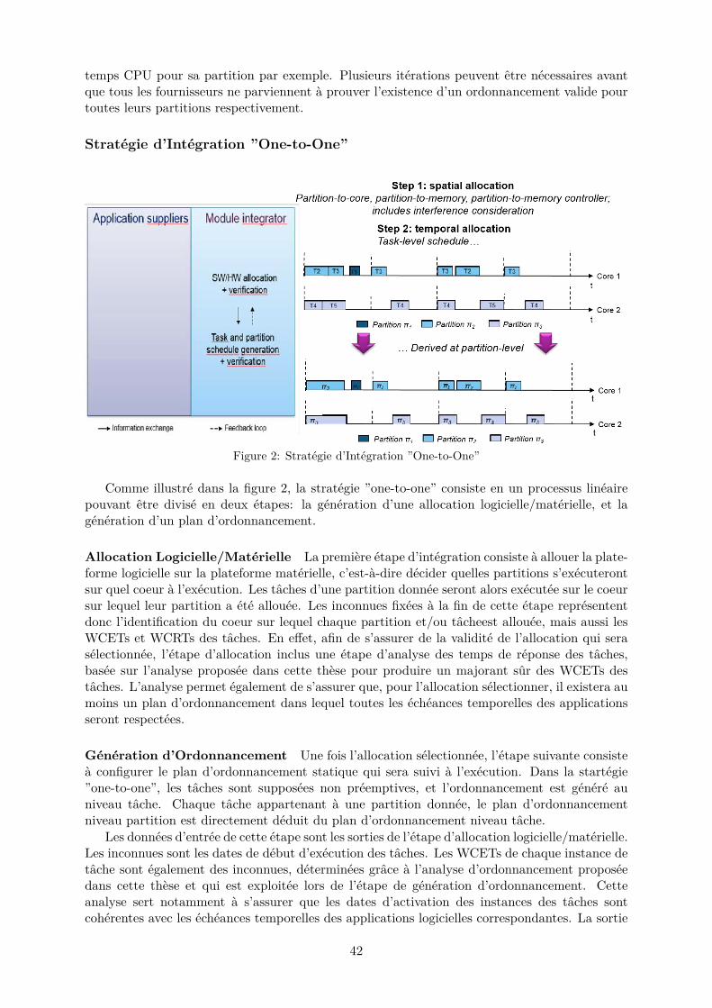
temps CPU pour sa partition par exemple. Plusieurs iterations peuvent etre necessaires avantque tous les fournisseurs ne parviennent a prouver l’existence d’un ordonnancement valide pourtoutes leurs partitions respectivement.
Strategie d’Integration ”One-to-One”
Figure 2: Strategie d’Integration ”One-to-One”
Comme illustre dans la figure 2, la strategie ”one-to-one” consiste en un processus lineairepouvant etre divise en deux etapes: la generation d’une allocation logicielle/materielle, et lageneration d’un plan d’ordonnancement.
Allocation Logicielle/Materielle La premiere etape d’integration consiste a allouer la plate-forme logicielle sur la plateforme materielle, c’est-a-dire decider quelles partitions s’executerontsur quel coeur a l’execution. Les taches d’une partition donnee seront alors executee sur le coeursur lequel leur partition a ete allouee. Les inconnues fixees a la fin de cette etape represententdonc l’identification du coeur sur lequel chaque partition et/ou tacheest allouee, mais aussi lesWCETs et WCRTs des taches. En effet, afin de s’assurer de la validite de l’allocation qui seraselectionnee, l’etape d’allocation inclus une etape d’analyse des temps de reponse des taches,basee sur l’analyse proposee dans cette these pour produire un majorant sur des WCETs destaches. L’analyse permet egalement de s’assurer que, pour l’allocation selectionner, il existera aumoins un plan d’ordonnancement dans lequel toutes les echeances temporelles des applicationsseront respectees.
Generation d’Ordonnancement Une fois l’allocation selectionnee, l’etape suivante consistea configurer le plan d’ordonnancement statique qui sera suivi a l’execution. Dans la startegie”one-to-one”, les taches sont supposees non preemptives, et l’ordonnancement est genere auniveau tache. Chaque tache appartenant a une partition donnee, le plan d’ordonnancementniveau partition est directement deduit du plan d’ordonnancement niveau tache.
Les donnees d’entree de cette etape sont les sorties de l’etape d’allocation logicielle/materielle.Les inconnues sont les dates de debut d’execution des taches. Les WCETs de chaque instance detache sont egalement des inconnues, determinees grace a l’analyse d’ordonnancement proposeedans cette these et qui est exploitee lors de l’etape de generation d’ordonnancement. Cetteanalyse sert notamment a s’assurer que les dates d’activation des instances des taches sontcoherentes avec les echeances temporelles des applications logicielles correspondantes. La sortie
42
de l’etape de generation d’ordonnancement est alors un plan d’ordonnancement statique pourlequel l’analyse a verifie qu’il menera toujours au respect des echeances temporelles a l’execution.
Evaluation
Les contributions de these ont ete evaluees sur plateforme reelle, c’est-a-dire sur un processeurmulticoeur identifie comme potentielle cible pour utilisation dans un systeme avionique. Nousavons selectionne le processeur P4080 de Freescale [9]. Le RTOS exploite pour l’ordonnancementest le VxWorks653 3.1 Multicore Edition de Wind River Inc [14]. Les problemes de program-mation par contrainte ont ete resolus en utilisant le solveur de contraintes de IBM/ILOG, CPOptimizer [6]. Pour effectuer l’analyse des temps d’execution en isolation des taches, nous avonsexploite le logiciel aiT Analyzer d’Absint [2].
L’evaluation des deux strategies a revele leur pertinence et surete, par l’absence de violationd’echeance temporelle, dans toutes les configurations testees sur plateforme reelle et pendanttoute la duree de l’observation du comportement du systeme.
Le gain en optimisation des systemes via l’exploitation de la programmation par contraintesa ete observe lors de la comparaison des resultats des strategies d’integration ”one-to-one” et”one-to-all” a une strategie basee allocation et ordonnancement ignorant completement les in-terferences multicoeur. Cette derniere strategie correspond a l’etat de l’existant avant notrethese, a notre connaissance. Les resultats montrent que les configurations selectionnees en sortiede l’une ou l’autre de nos strategies a toujours un taux d’utilisation total plus bas que dans lessolutions exhibees par la strategie ignorant les interferences.
Pour les deux strategies proposees dans cette these, chaque probleme de programmationpar contraintes est resolu en quelques secondes. Une allocation et un plan d’ordonnancementgeneres manuellement auraient pris plusieurs jours, ne serait-ce qu’a cause du calcul de WCETset WCRTs qui sont complexes. Sans compter qu’il serait tres difficile de generer un ordonnance-ment optimise manuellement, ce qui aurait pris plusieurs tentatives manuelles. Par oppositiona une recherche manuelle, il est plus facile d’essayer differentes configurations, les valides etles invalides etant clairement et rapidement exposees par le solveur de contraintes. De plus,l’utilisation de l’une de nos strategies d’integration supprime le risque de detection tardive de con-figurations non valides, les verifications temporelles etant menees en simultane avec l’allocationet l’ordonnancement respectivement.
Finalement, une autre nouveaute apportee aux concepteurs de systemes par nos strategiesd’integration est le gain de visibilite sur l’impact des interferences multicoeur sur l’existence deconfigurations valides. Le processus d’integration est maintenant plus flexible, car le gain detemps et d’efforts permet aux concepteurs de systemes d’effectuer des verifications supplementaire,d’essayer de nouvelles combinaisons d’allocations (par exemple allouer plus d’applications aumeme module), etc.
Pour resumer, les objectifs de la these en ce qui concerne la compatibilite des staregiesd’integration proposees avec les contraintes de certification ont ete atteints. Les objectifs sec-ondaires de l’optimisation de la conception et de la reduction du time-to-market ont egalementete atteints grace a l’exploitation des techniques de programmation par contraintes pour au-tomatiser les etapes de chaque strategie d’integration.
En plus des aspects fonctionnels des contributions de cette these, la genericite des strategiesproposees a egalement ete verifie. Tout d’abord, on peut remarquer l’independance des strategiesvis-a-vis de la plateforme materielle exploitee et du RTOS: les seuls adherences se trouvent auniveau de la modelisation de la plateforme multicoeur, et ces adherences sont soit: (i) deselements basiques de modelisation multicoeur, comme par exemple la frequence CPU; (ii) soitdes parametres materiels caracteristiques du composant modelise, present dans tout composantdu meme type et dont la valeur est obligatoirement fournie par le concepteur de processeur.Ainsi, les travaux presentes dans cette these peuvent etre utilises pour tout multicoeur base bus,
43
et ne se restreignent donc pas a une unique famille de processeurs particuliere.
Conclusions
La strategie d’integration ”one-to-all” est basee sur une approche statique SMP ou, au momentde l’execution, une seule application est executee sur tous les noyaux d’une plateforme multi-coeur. La strategie d’integration ”one-to-one” repose sur une approche AMP statique ou chaquenoyau est considere comme un processeur distinct a l’execution, chaque coeur ayant son propreschedule.
Pour couvrir la verification temporelle du systeme, les deux strategies comprennent: (i)une analyse de faisabilite exploitee pendant la phase de configuration de l’allocation, et (ii)une analyse d’ordonnancement exploitee dans le probleme d’ordonnancement. L’analyse defaisabilite est basee sur une derivation de l’analyse du temps de reponse pour s’adapter auxarchitectures IMA et aux plateformes multicœurs. Un modele d’interference a ete propose afinde produire un majorant superieur des delais d’interference dans la situation la plus defavorablesubies par chaque tache. L’analyse d’ordonnancement reutilise le modele d’interference, ainsi quela connaissance des plans d’ordonnancement des autres coeurs respectivement afin de calculerdes majorants superieurs de WCET pour chaque instance de tache dans une hyperperiode, etverifie que toutes les echeances temporelles sont respectees.
Enfin, chaque etape de chaque strategie d’integration est exprimee sous la forme d’unprobleme de programmation par contraintes, afin de permettre l’automatisation des activitesd’allocation, generation et verification d’ordonnancement. De plus, l’exploitation des techniquesde programmation par contraintes permet egalement d’economiser du temps et et raccourcirle cycle de conception du systeme, mais aussi de reduire les efforts a fournir pour effectuer lesdifferentes verifications. Cela permet egalement d’optimiser les choix d’allocation et ordonnance-ment, via la definition de fonctions objectives dans chaque probleme exprime, afin de selectionnerla solution de configuration la plus optimisee suivant des criteres industriels.
Degre de Confiance des Analyses Temporelles Deux analyes sont proposees. La premiereest une analyse de faisabilite, ou analyse temporelle servant a determiner si, pour une alloca-tion des applications et taches sur les coeurs d’un multicoeur donnee, il sera toujours pos-sible de trouver un plan d’ordonnancement dans lequel toutes les echeances temporelles dela plateforme logicielle seront toujours respetees a l’execution. La seconde est une analysed’ordonnancement, ou analyse temporelle servant a determiner si, pour une allocation et unalgorithme d’ordonnancement donnes, toutes les echeances de la plateforme logicielle serontrespectees a l’execution.
Les deux types d’analyses proposees reposent sur un modele statique d’interference. Aucunehypothese n’est faite sur les dates d’arrivee des requetes memoire au niveau de l’interconnectou bien des controleurs memoires. Le but des modeles construits est de deriver une enveloppesuperieure des situations pire cas d’interference inter-coeurs de maniere a produire un majorantabsolu des WCET et WCRT des taches d’une application IMA. Ainsi, les valeurs d’interferencecalculees pour chaque tache correspondent a une valeur toujours superieure a la reelle dureed’interference que cette meme tache peut subir dans la pire situation possible. On peut dire queles analyses proposees ont la meme valeur qu’une analyse exhaustive, sous couvert de l’hypothesede composabilite de la plateforme materielle exploitee. A ce titre, l’analyse resultant est sure,par opposition a une analyse basee sur un echantillon de mesures par exemple.
Modularite et Flexibilite des Modeles d’Interference et d’Analyses Temporelles Pro-poses. Les analyses temporelles presentees dans cette these permettent de verifier la validitedes coix de configurations faits lors de l’integration de la plateforme logicielle sur la plateformematerielle. L’un des avantages notoires du modele d’interference propose est la modularite desequations du modele: il est possible de modifier ou raffiner les modeles d’interferences de maniere
44

rapide et sans necessiter une refonte complete des aalyses temporelles exploitant les equationsmodelisant les interferences.
Une telle modularite rend egalement flexible l’utilisation des analyses proposees. Dans lespremieres phases de developpement d’un nouveau logiciel IMA, il est possible de remplacerles equations detaillees du modele d’interference par un modele gros grains pour se faire uneestimation des interferences encore plus en avance de phase. L’analyse permet alors de donner,pour chaque allocation ou plan d’ordonnancement evalue, une reponse quasi instantanee quanta la faisabilite du respect des echeances temporelles.
La flexibilite des modeles d’interference proposes se manifeste egalement de par le fait qu’ilspeuvent etre utilises a la fois dans la verification de faisabilite d’une allocation, et dans laverification d’ordonnancement une fois des dates d’activations selectionnees. Malgre le faitque les taches et les partitions soient modelisees via des parametres differents dans les etapesd’allocation et d’ordonnancement, aucune modification des modeles d’interference n’a a etrefaite, la difference etant faite de facon logique au niveau des equations de calcul de WCET pourl’allocation et pour l’ordonnancement.
En conclusion, de telles caracteristiques conferent aux techniques d’analyse temporelle pro-posees dans cette these une propriete significatie pour l’industrie: l’adaptation a l’evolution desplateformes, a la gestion d’osbolescence, mais ausi l’adaptation des modeles d’interferences auxavancees realisees dans la litterature au fil des annees futures.
Portabilite et Reutilisation des Contributions. Les deux principaux freins a l’extensiondes techniques d’analyse statique monocoeur aux architectures multicoeur sont:
• La complexite des architectures multicoeur. Les ressources partagees impliquentun certainnombre de couplage de chemins conduisant a l’explosion du nombre d’etats a considererdans le cadre d’une analyse temporelle exhaustive comme le sont les analyses statiquesmonocoeur exploitees dans l’avionique.
• Le manque d’informations sur certaines ressources partagees du a des protection de pro-priete intellectuelle par les fabricants de processeurs. Ce manque vient augmenter leprobleme des ressources dont le comportement n’est pas deterministe et ne peut etremodelise de maniere pertinente, par exmeple les ressources dont l’arbitrage exploite uneheuristique basee sur les performances moyennes et les derniers arbitrages passes.
A notre connaissance, aujourd’hui, toute tentative pour realiser une analyse WCET au niveaucode et de maniere statique a conduit a une explosion du nombre d’etats a considerer dans laditeanalyse, et donc a un probleme intractable.
Les analyses temporelles proposees dans cette these sont des analyses statiques, et ne tombentpas dans ce probleme d’explosion du nombre d’etats ni d’intractabilite. Cela est du au choixstrategique d’effectuer l’analyse a un degre d’abstraction plus eleve: au niveau ordonnancementplutot qu’au niveau code. Les modeles des ressources partagees causant des interferences re-posent uniquement sur des parametres essentiels de ces ressources, en ce sens qu’il s’agit deparametres dont le fabricant est tenu de donner la valeur lors d ela commercialisation de laressource correspondante. Ainsi, cette these a su gerer a la fois le probleme de complexite desarchitectures multicoeur puisque les contributions ne risquent pas de tomber dans le problemed’explosion du nombre detats et d’intractabilite, et le manque d’informations par protectionintellectuelle.
Pourquoi Deux Strategies d’Integration Le fait de proposer deux strategies differentespour l’integration a ete motive par les differentes proprietes des deux propositions. Bien que lastrategie d’integration ”one-to-all” respecte toutes les exigences obligatoires pour la certificationdes systemes aerospatiaux, la strategie ”one-to-one” offre autant de reduction du nombre deplateformes embarquees dans un systeme avionique que possible (c’est-a-dire en utilisant destechniques d’analyse compatibles avec DO-178) pour les fonctions DAL A tout en utilisant
45

l’analyse temporelle proposee dans cette these. Cependant, la strategie d’integration ”one-to-one” ne premet pas de repondre a l’exigence de partitionnement robuste pour les fonctions DALA, ce qui implique de determiner un autre moyen que le partitionnement robuste pour empecherla propagation de faute en cas de probleme, et parvenir a convaincre les autorites de certificationde la validite du moyen mis en place. Cela signifie qu’en cas d’usage pour des plateformesnecessitant un partitionnement robuste des applications, la strategie ”one-to-one” necessite unsavoi suppelmentaire non disponible aujourd’hui, contrairement a la strategie ”one-to-all”, quipourrait immediatement etre utilisee dans un contexte industriel.
La strategie d’integration ”one-to-one” est tout de meme proposee comme contribution decette these, car elle peut etre utilisee:
• Pour des fonctions moins critiques pour lesquelles il n’est pas obligatoire d’interdire lesacces simultanes aux ressources partagees au moment de l’execution, et pour lesquelles unprocessur de developpement incremental n’est pas requis.
• Pour la conception de modules IMA dans lesquels une seule application par module estintegre, chaque application etant divisee en plusieurs partitions. Dans ces cas, toute in-terference inter-coeur demeure intra-application. Ainsi, on peut considerer que les modulesresultants respectent la contrainte de partitionnement robuste des applications IMA. Celavise tout DAL, y compris les applications DAL A.
• Pour l’integration non IMA, c’est-a-dire pour porter un logiciel non IMA – les commandesde vol par exemple – sur un processeur multicoeur.
Pour de telles fonctions, l’utilisation de la strategie d’integration ”one-to-one” conduit a desconceptions optimisees dans lesquelles la reduction du nombre de processeurs a embarquer pourintegrer toutes les applications avioniques du systeme a ete realisee autant que possible. Danstoutes les autres configurations, c’est la strategie d’integration ”one-to-all” qu’il faudra exploiter.Ainsi, les deux strategies d’integration proposees dans cette these sont complementaires l’unede l’autre.
Perspectives
Les strategies d’integration et analyses temporelles associees dans cette these fournissent unebase de travail pour l’allocation logicielle/materielle et la generation de plan d’ordonnancementverifiees en avance de phase pour des systemes IMA bases sur multicoeur. A ce titre, cer-taines pistes de travaux futurs peuvent etre identifiees, comme par exemple l’experimentationde differents criteres d’optimisation pour les problemes degeneration d’ordonnancement definisdans chaque strategie d’integration.
En dehors de la charge CPU, une preoccupation commune des concepteurs de systemesavioniques est le nombre de changements de contextes de partitions impliques par un pland’ordonnancement donne. Ces changements de contexte representent des delais venant s’ajoutera l’execution des traitements logiciels de l’application concernee, et ils ne sont en general pascomptabilises dans les budgets de temps CPU definis pour chaque fenetre de partition. Eneffet, la commutation de partition n’est pas gratuite et le temps passe a changer les contextespeut entraıner des depassements de fenetres temporelles des partitions dans une hyperperiode.Par consequent, il pourrait etre interessant de chercher a optimiser les plans d’ordonnancementgeneres par nos problemes de programmation par contrainte de maniere a minimiser le nombretotal de changement de contexte de partition. A notre connaissance, la litterature n’offre aucuneapproche – autre qu’empirique – pour la modelisation des changements de contexte [106, 75]. Laraison principale tient a l’adherence forte des delais de changement de contexte, a la plateformematerielle exploitee. Les traitements realises lors d’un changement de contexte dependent de
46
l’OS et du processeur utilises, et ne sont pas divulgues dans les details par les fabricants cor-respondants. Pallier a ce manque pourrait correspondre a une perspective future interessanted’amelioration des travaux de cette these.
Une autre optimisation possible des plans d’ordonnancement generes est la reduction desinterferences inter-coeur. Celle-ci peut etre realisee en reduisant autant que possible le nom-bre total d’executions paralleles sur les differents coeurs du multicoeur exploite. Un objectifd’optimisation encouragerait la selection de plans d’ordonnancement dans lesquels aucune tacheexploitant le meme chemin vers la memoire ne sont ordonnancees simultanement, les seulesexecutions paralleles alors plannifiees visant des couples de tache qui ne peuvent interferer lesunes avec les autres. Deux taches n’interfere pas si elles ne sont pas allouees au meme controleurmemoire par exemple.
Definir une fonction objectif minimisant les interferences signifierait alors que, chaque foisque cela est possible, le solveur de contraintes guidera le processus de resolution du problemed’ordonnancement vers des plans d’ordonnancement dans lesquels aucune interference inter-application n’a lieu. Il est important de noter que si une telle situation est rencontree, cela sig-nifie qu’il est eventuellement possible d’augmenter le nombre de partitions pouvant etre integreessur le meme module. Cela favorise encore plus la reduction du nombre de processeurs embarquesdans le systeme correspondant, et donc la reduction du volume et de la charge totale du systemefinal.
Outre l’optimisation de la conception, une autre piste interessante serait de raffiner davan-tage le modele d’interference exploite dans les analyses temporelles, de maniere a couvrir plusde ressources materielles partagees par les coeurs d’un multicoeur au moment de l’execution.Compte tenu de la complexite et de l’explosion du nombre d’etats a analyser lorsque l’on modelisetoutes les ressources partagees, un compromis doit etre trouve entre la determination d’un bonniveau d’abstraction du modele d’interference et le nombre de ressources partagees representeesdans le modele d’interference. Par exemple, pour encourager la reutilisation de l’etat de l’art,la representation des interference multicœur proposee par Altmeyer et al. [19] est plus detailleeque dans cette these, et par consequent pourrait produire des majorants superieurs moins pes-simiste des WCRTs et WCETs des taches. Cependant, ces travaux sont concentres sur l’analysed’ordonnancement, et partent d’une allocation et un plan d’ordonnancement predefinis en entreedu probleme; d’autre part, l’ordonnancement hierarchique telle que definie dans les architec-tures IMA n’est pas consideree. Ainsi, il serait interessant de chercher a fusionner les travauxd’Altmeyer et al. avec les contributions de cette these.
Pour finir, comme mentionne precedemment, en tant que premiers travaux vers une strategied’integration complete pour l’exploitation de multicoeurs dans les systemes avioniques, nousnous sommes limites a un seul processeur multicoeur pour etudier les interferences, l’allocationet l’ordonnancement d’applications IMA. Les systemes avioniques integrent generalement plusd’un processeur a bord, relies entre eux a travers differents reseaux d’interconnexion. Main-tenant que cette these apporte des techniques d’analyse temporelle IMA multicoeur, il seraitinteressant de generaliser nos contributions de these a une plateforme materielle constitue deplusieurs multicoeurs interconnectes. La palteforme logicielle alors consideree consisterait enl’integralite des applications logicielles devant etre embarquees dans le systeme avionique a con-cevoir. Le probleme d’allocation chercherait a allouer les applications aux differents multicoeurs,et l’ordonnancement comprendrait les delais de communication inter-modules.
Dans la litterature, les travaux cherchant a traiter ces deux activites font habituellementl’hypothese qu’a l’echelle de chaque processeur pris separement, il sera possible de trouver uneallocation et un ordonnancement valides. Ainsi, notre these est complementaire de ce genre detravaux. Il serait alors interessant de combiner les deux ensemble pour gerer l’integration dessystemes distribues exploitant des multicoeurs.
47
Organisation du Manuscrit
Les premiers chapitres constituent les fondements de cette these. Le chapitre 1 presente lesdefis poses par les multicores pour l’industrie aerospatiale, la problematique de cette these, ainsiqu’une breve description des contributions de cette these.
Le chapitre 2 fournit les connaissances de base necessaires pour comprendre les contribu-tions de cette these: la terminologie est brievement presentee avant de decrire le concept IMAet les reglementations de certification imposees sur les systemes aerospatiaux. Le chapitre sepoursuit ensuite avec une description des connaissances necessaires pour comprendre la theoriede l’ordonnancement et les theoremes exploites comme base des contributions de these.
Le chapitre 3 presente un apercu de la litterature autour des challenges poses par l’integrationde systemes temps-reel dans des environnements multicœur.
Les quatre chapitres suivants presentent les contributions de cette these. Sauf mentionexplicite dans ces chapitres, l’ensemble des travaux decrits dans ces chapitres est la seule con-tribution de l’auteur de cette these.
Le chapitre 4 presente tous les modeles et parametres exploites dans les contributions dethese, les hypotheses de cette these ainsi qu’une presentation generale des strategies d’integrationproposees dans cette teshe. Ensuite, sont presentes les modeles d’architecture logicielle etmaterielle qui sont consideres dans cette these. Le chapitre termine par une breve descrip-tion des contraintes considerees dans les problemes d’allocation et d’ordonnancement abordesdans cette these.
Le chapitre 5 presente les methodologies d’analyse temporelle qui ont ete mises en œuvre danscette these. En particulier, le modele d’interference et les equations exploitees pour le calcul desWCET et temps de reponse pire cas (WCRT) des taches sont exposes. Deux types d’analysetemporelles sont propsees, en tant qu’analyses exploitees respectivement lors de la recherched’allocation logicielle/materielle et lors de la configuration d’un plan d’ordonnancement. Lechapitre se termine par une sous-partie resumant les analyses proposees et discutant de leursavantages et de leurs limitations.
Le chapitre 6 presente les deux strategies proposees dans cette these pour l’integration IMAsur COTS multicoeur. Un bref apercu de chaque strategie d’integration est donne en premier,avant de presenter separement – dans les details et dans l’ordre chronologique – les activitesrealisees dans chaque strategie. Le chapitre se termine par une sous-partie qui resume lesstrategies d’integration proposees, puis discute des avantages et des inconvenients de chaquestrategie.
Le chapitre 7 presente l’evaluation des travaux reaalises dans cette these: des explicationssur les experimentations menees sont d’abord fournies, avant que plus d’information sur la facondont la plateforme logicielle de test a ete construite ne soient donnees. Le chapitre poursuitavec la presentation et l’analyse des resultats obtenus, et se termine par une section resumantles resultats generaux et discutant des realisations et des limitations rencontrees lors de la miseen place des activites de test.
Pour terminer, le chapitre 8 propose un bref resume des contributions proposees dans cettethese, ainsi qu’une discussion globale en ce qui concerne le respect des objectifs principaux decette these, avant de donner une conclusion generale sur les realisations et de finir avec lestravaux futurs que cette these propose en perspectives.
48
Chapter 1
Introduction
1.1 Motivations
For hard real-time systems, predictable delays for software runtime execution are as important asthe correctness of the computational results. In particular for safety-critical systems, a failure todeliver correct results that are both correct and on time may lead to a system-level dysfunctionwith severe consequences, such as significant loss of money or human life. Aerospace systemsfall into this category of systems, and must therefore undergo a strictly regulated design andverification cycle coupled with a strict certification process before being allowed to be operationaland commercialized. For instance, regarding the safety critical software embedded in an avionicsystem, each software operation must be analyzed at design time in order to derive a safe upper-bound on its execution time duration at runtime, but also in order to configure accordinglyand in advance the runtime behavior of the entire system, all the while being able to show thecorresponding verification results as a justification to certification authorities to convince themof having successfully done so.
Certification is very important when designing an aerospace system, and represents a signifi-cant amount of effort and verification in order to achieve compliance to certification regulations.Whenever a modification is performed on a part of an avionic system, all parts of that systemwhich are impacted by the modifications must be re-verified and their compliance to certificationregulations re-proven.
One way to try and reduce the additional time and effort spent due to design modificationsis to adopt a design approach favoring modularity and independence. For instance, the softwareembedded in an avionics system represents several applications, which are not necessarily devel-oped by the same application supplier. However, each application is developed independentlyfrom one another for safety reasons. This also enables designers to make sure that each appli-cation can be analyzed independently from each other, so that modifying one function has noimpact on all other functions. As such, only the modified function(s) will need to be re-verifiedand re-certified; the resulting development, verification and certification processes are then saidto be incremental [172].
In addition to incremental certification, the modularity of a system is also enhanced by im-plementing an Integrated Modular Avionics (IMA) architecture [1], according to which softwareapplications are further divided into sub-elements that are to be executed strictly independentlyfrom each other at runtime, thus ensuring a temporal and spatial isolation. Such a separationis often referred to as time and space partitioning.
To sum up, the concepts of incremental certification and IMA architecture both ensure themodularity of an avionic system, and require verification analyses to be performed in the samespirit of separation of concerns. In that sense however, the knowledge and experience of avionicsystem designers are crucial to certify avionics systems.
The software embedded in aerospace systems is preferably integrated on hardware platforms
49
that have a long in-service history in the aerospace industry, and which are deemed reliableaccording to systems designers expertise. The main motivation behind such a choice is to relyon electronics which has had time to be extensively tested and has then been proven to becompatible with all requirements of the corresponding avionic systems. Doing so facilitates thedesign of future avionic systems as well, since it is easier to reuse hardware which behavioralcharacteristics are well known from experience due to usage in previous systems.
Until now, hardware platforms embedded in avionic systems contain only single-core proces-sors. However, now that processor manufacturers are capable of producing powerful multicoreprocessors, it is predicted that manufacturers will definitively stop producing single-core pro-cessors, including the ones embedded in current avionics systems. Avionics industries do notrepresent a market share big enough for processors manufacturers. As such, processors man-ufacturers would not benefit from keeping producing single-core processors only for avionicsindustries. As a consequence, avionics industries will soon have no other choice than to moveto multi- and/or manycore processor designs.
The advent of multicores can be beneficial for design and cost optimization by reducingthe embedded weight and energy in avionic systems, one core being able to handle the loadof one previous single-core. However, all certification regulations and design procedures linkedto software must be updated in order to take into account multicore-based hardware platforms[109]. For instance, a new definition of IMA architecture for multicore platforms must be set,since by nature multicore architectures go against the principle of independence of softwareexecution at runtime. Indeed, because of the concurrent accesses to shared resources inside themulticore chip occurring at runtime, temporal isolation is difficult to achieve at runtime on amulticore platform.
Therefore, all analysis and verification activities usually taking place in a system design cyclemust be updated with tools and techniques capable of analyzing multicore platforms. Inter-coreinterference at runtime must be safely bounded during the analysis in order to be able to safelyconfigure in advance the runtime behavior of the system at design time. Only then, systemdesigners would be able to properly use multicore platforms for aerospace systems and to rebuildthe knowledge and know-how necessary to master multicore-based avionics systems.
Such changes are problematic in the case of software porting from single- to multicore sys-tems, mainly because of the current lack of software analysis tools or techniques capable ofupper-bounding tasks Worst-Case Execution Times (WCET) safely [171]. Concurrent resourceaccess requests generated by each core cause additional interference at runtime, leading to sig-nificant waiting delays increasing tasks execution times. In addition, the level of complexity andcoupling of the resource sharing in multicores makes it difficult or even impossible for currenttiming analysis techniques for safe WCET upper-bounding to be adapted to multicore environ-ments without becoming intractable or overly pessimistic. Another difficulty adding up to thecomplexity of shared interference is the fact that information on the multicore architecture thatis crucial for the WCET analysis is undisclosed in most Components Off-The-Shelf (COTS)multicores, due to protection of intellectual property rights and patented designs. Moreover,some request arbitration policies might be too complex to be properly represented as well, sothat there is no certainty that any workaround proposed to cope with these issues will lead toa safe timing analysis for multicore COTS.
In the end, there currently exists no solution to the challenge of safe WCET analysis onmulticore. Without such solution, resource contentions cannot be properly bounded beforehand,so that there is no way of configuring a safe runtime behavior in advance, nor of ensuring inadvance that all deadlines of a system will never be violated at runtime. Such lack of safe WCETanalysis techniques for multicore systems is jeopardizing the exploitation of multicore platformsin aerospace systems, which makes it one of the most studied research topic both in academiaand industry [90, 129, 119, 66, 64].
As mentioned before, the difficulty of analyzing timing behavior on multicore systems exists
50
for all real-time systems. The literature is full of various propositions to tackle the problem athand [64]:
• Some works propose new middleware services to monitor every access to shared hardwareresources, in order to enforce deterministic runtime behaviors by getting rid of inter-coreinterference [46];
• Other works propose new multicore designs where each core has its own private resources[7, 181, 149];
• Similar works focus on implementing new hardware devices to be added to an existingarchitecture in order to control the sharing of some resources, hoping that such new deviceswill either be implemented in custom multicore processors for industries or selected byplatform vendors for their next COTS generation [111, 130, 170];
• A different kind of strategy that exists in the literature as well consists in proposing newexecution models for multicore-friendly software development [58];
• Other works propose new timing analysis techniques for shared resources interferencebounding or estimation, relying or not on some software and/or hardware modifications[19, 67, 85, 91, 111, 116, 118, 122, 127, 51].
Each approach has its own advantages. However, the first drawback is that all of themare not considered sufficient or valid for the certification of IMA architectures. The other maindrawback common to all approaches in the literature is the non respect of key aerospace systemsrequirements, to which they consequently cannot be applied without high costs, dependence tosome manufacturer or giving up some key principles of the current certification acceptance pro-cess.
This thesis has been initiated and funded by Airbus Group Innovations Toulouse, as aCIFRE (training contract for performing research in private companies) PhD with the IRITlab in Toulouse. The main goal of the thesis is to propose an approach for integrating legacyIMA software – i.e. sequential software developed for single-core platforms – onto a multicoreprocessor, without any hardware nor software modification: the approach much comply as muchas possible with incremental certification acceptance process and key IMA concepts. To do so,multicore interference must be taken into account in the proposed contributions. In this thesis,we focus on inter-core interference due to sharing access to the main memory.
The motivation of this thesis is to stick as much as possible to current industrial processes,in order to maximize the chances of acceptation of the proposed contributions by aerospaceindustries and certification authorities by minimizing the changes and effort of adaptation thatwould be necessary to adopt the newly proposed process.
A secondary goal of this thesis is to improve design optimization by benefiting from theperformance gain that can potentially be brought by multicore processors.
Finally, the following list gathers strong choices that have been selected as guidelines for ourcontributions, in order to increase their chances of being considered as a solution for the nextgeneration of aerospace systems:
• The proposed contributions must be applicable to DAL A IMA applications. Indeed, asbriefly mentioned before, every attempt of solution proposed in the litterature is eithernot applicable to IMA systems, or requires a high amount of modifications and efforts inorder to be used for IMA systems; moreover, no solution targeting IMA systems covers allof the multicore challenges hindering the usage of multicores in avionics systems.
• The proposed contributions should not be specific to one particular hardware platform orrely on the know-how of some specific supplier;
51
• In particular, the contributions should not rely on any hardware modification or assumespecific hardware architecture characteristics, so that COTS platforms can be used insteadof implementing ASICs or relying only on one specific COTS product line or one specificCOTS manufacturer. The contributions should rely only on COTS-friendly configurationmechanisms instead, so that no special additional hardware is needed;
• The contributions should not involve any software modification as well, so that legacysoftware can be reused and no special additional study and/or regulations are required tocertify the software platform considered, and the overall approach proposed for multicoreintegration can be used in an as nearest future as possible;
• The approach proposed in the thesis should reuse as much as possible existing works fromthe literature to cope with multicore challenges, even if these works represent only partialsolutions to the multicore challenge. Our motivation is to promote research-to-industrytransfer; however, it is also important that only realistic techniques should be considered,fitting real world constraints of industrial systems and processes;
• In the same line of idea, the realism of the proposed solutions is mandatory, even if itmeans designing under-optimized systems. In particular, it is important not to make anyassumption that is unapplicable to current COTS multicores or ignores current unavoidablesituations at runtime.
• The thesis outcome should promote as much automation as possible in the proposed con-tributions, in an effort to shorten the time-to-market but also to reduce additional effortsto be made by suppliers and integrators when handling new technologies such as multicoresin future aerospace systems.
• Finally, the thesis contributions should respect the current development and certificationprocesses as much as possible. Even if they are not suited for multicore environments,respecting as many legacy design and certification rules as possible is truly likely to helpreducing the time that would be spent negotiating with certification authorities to inves-tigate new mechanisms and configuration choices.
The proposed contributions are based on a generic, bus-based multicore architectural model.All assumptions about affecting the hardware configuration can be implemented using classicconfiguration choices usually offered in COTS platforms.
1.2 Contributions
This thesis proposes two complete methodologies or strategies for IMA integration on multicoreCOTS. Each one has different advantages and different drawbacks, and therefore may respec-tively be used for different situations and systems to be designed. One strategy fits all avionicand certification requirements but is likely to result in poorly optimized designs, and the otherone generates configurations that are as optimized as possible but does not respect some ofthe current key certification requirements, which makes it not suitable for applications with thehighest levels of criticality.
The proposed integration strategies are said to be ”complete” because we provide all themetrics necessary to go through all steps of the proposed integration strategies. They cover theallocation of the software platform onto the hardware platform, the schedule generation but alsotiming analyses. To sum up, the contributions of this thesis consist in:
• Interference-aware timing analysis models and techniques for early timing verification andenforcement of a deterministic runtime behavior of the system: in particular, we propose(i) a mathematical model of shared resources exploited to derive a safe upper-bound ontasks worst-case interference delay due to each shared resource respectively, and (ii) an
52
approach for performing a safe response time analysis for IMA architectures in multicoreenvironments. The resulting analysis has been derived into two different approaches:one dedicated to verifying the validity of a software/hardware allocation by performing aresponse time analysis, and one dedicated to deriving safe WCET upper bounds for tasksand CPU time windows for partitions when an allocation and a schedule have been set.This contribution is presented in details in chapter 5, and has been published in [116].
• A Constraint Programming (CP) formulation for performing automated, optimized andsafe software/hardware allocation of IMA applications onto multicore platforms. Theapproach is safe in the sense that the feasibility of the solution selected by the constrainedprogram is ensured since the timing analysis implemented in this thesis is embedded as aconstraint of the CP. This contribution is covered in chapter 6 and has been published in[118].
• A CP formulation for performing automated, optimized and safe schedule generation forIMA applications on multicore platforms. It is said to be safe because the constrainedprogram embeds the schedulability analysis proposed in this thesis as a constraint, inorder to ensure the validity of the solution selected by the constrained program. Thiscontribution is covered by chapter 6 and has been published in [116, 118]. This contributionhas been mentioned in our pulications [116, 118, 117].
• Two processes for safe IMA integration on multicore platforms: as mentioned before, oneof the two respects all most important certification characteristics of current IMA systems,and the other offers maximum design optimization for less critical IMA applications. Eachstrategy covers the allocation of the IMA software platform onto the multicore platform,and the generation of a schedule for each core of the multicore processor. To do so,safely and automatically in order to save time and effort, the three previously mentionedcontributions of this thesis are exploited. This contribution is extensively explained inchapter 6, and has been published in [117].
The work presented in this thesis has been evaluated on a real platform. The evaluationhas been performed on the Freescale/NXP QorIQ P4080 processor [9]. A software case studyhas been built by the author of this thesis by exploiting open source code from the TacleBenchbenchmark suite [13]. We applied the proposed strategies for allocating and scheduling the con-structed IMA case study on the P4080 processor [9] using Wind River IMA RTOS, VxWorks6533.1 Multicore Edition [14]. The evaluation consists in implementing on the P4080 target theconfiguration selected when applying one of our two strategies, and verifying that no deadlinewas missed when observing the system’s runtime behavior.
The following paragraphs describe in more details each proposed contribution.
Interference Bounding and Safe Multicore Timing Analysis
This thesis proposes a sufficient feasibility test that is interference-aware, and compatible bothwith IMA applications and both homogeneous and heterogeneous multicore processors. To doso, we propose a mathematical model of the main memory and interconnect to be exploited toperform a static timing analysis and derive safe upper-bounds of tasks interference delays dueto shared resources. The resulting analysis includes safe WCET and WCRT upper-bounding.The model is based on an extension of the classic response time analysis in order to fit IMAarchitectures and multicore environments. It also includes the computation of safe upper-boundson multicore interference. Such bounds are crucial to formally prove the feasibility of the system,but also to build a safe schedule which has been verified beforehand to guarantee a deterministicbehavior at runtime. Detailed explanations on the proposed timing analyses are provided inchapter 5.
53
Allocation Problem
In this thesis, we use the expression allocation problem to address concerns about how thesoftware platform should be spatially allocated to the cores and memory of a multicore platform,i.e. (i) on which core a given partition (resp. task) is going to be scheduled at runtime, (ii) whereits memory context should be stored in DRAM and (iii) if more than one memory controlleris present on the hardware platform, which one it will exploit at runtime. No mention of timemanagement or time slicing is mentioned in such problems.
As a second contribution, we exploit the resulting IMA, multicore interference-aware timinganalysis described in the previous subsection, in order to implement a CP formulation for thesoftware/hardware allocation. The proposed timing analysis consists in a sufficient condition forfeasibility, and is defined as a constraint to be verified by the variables of the allocation problem.During the allocation process, the module integrator decides, for a given module consisting of agiven multicore processor, on which core each partition or task will be scheduled. In the caseof partitioned scheduling on a multicore processor, the integrator should decide on which coreeach partition will be allocated. An allocation then refers to a static mapping of each partitionor task of the IMA applications to the cores of the multicore processor.
As mentioned earlier, the safeness of the selected allocation is guaranteed by exploiting theproposed feasibility analysis to guide the design space exploration, so that the existence of aschedule where all timing requirements will always be met at runtime is guaranteed as soon as theallocation is set. Eventually, using constraint programming to set the allocation configurationenables to save time but also effort during the design cycle of a given system, the allocationproblem being NP-hard and WCETs upper-bounding equations being complicated enough toeasily cause inadvertent errors when computed manually.
In addition, potential time is saved when using constraint programming also because ofthe fact that expressing all timing constraints in the allocation problem reduces the risk of latedetection of invalid allocations. Since all requirements of the system are expressed as constraints,and if one of them cannot be fulfilled by any solution of the allocation problem search space, thenthe expressed allocation CP is able to raise awareness of the situation to the software integratorand designers. Integrator and designers then know that some modifications must be performeduntil a valid solution can be found. Without such early detection of potentially problematicsituations, the length of the system design cycle would have been extended. Indeed, the nonvalidity of the selected allocation would have been detected later only, or may even not havebeen detected at all, which would have had catastrophic consequences at runtime, for instancea deadline miss in the context of a critical operation.
Scheduling Problem
In this thesis, we use the expression scheduling problem to address concerns about how elementsof the software platform (tasks and/or partitions) should be scheduled on the cores of a multicoreplatform, i.e. how to distribute CPU time slices to the tasks and/or partitions of the softwareplatform. In IMA systems and for any critical software in general in avionics systems, staticschedules are built and configured in advance, to make sure the runtime behavior has beenverified and approved in advance at design time. Such static CPU time slicing implies definingin advance time intervals, each interval being temporally defined by a duration (or time budget)and a start date (or activation offset).
The safety of the generated schedules is guaranteed by exploiting the timing analysis proposedin this thesis to verify that all timing requirements will be enforced at runtime. In particularin the scheduling problem, activation offsets and WCETs upper-bounds are computed in orderto build a static schedule for partitions and/or tasks in one complete cycle of repetition ofthe schedule, also called MAjor Frame (MAF). In addition to guaranteeing the safety of thefinal schedules, the timing analysis embedded in the scheduling problem formulation guides the
54
design space exploration when selecting activation offsets, so that the finally selected schedule isoptimized as much as possible given the characteristics of the system. Eventually, analogouslyto the allocation problem, using constraint programming to build schedules saves time but alsoeffort, and helps preventing late detections of invalid configurations.
Methodologies for Safe Integration of IMA
As a final contribution, we exploit the proposed timing analyses, allocation and schedule gener-ation CP formulations to implement methodologies for the safe integration of IMA applicationsonto multicore platforms.
We propose two strategies. Our first integration strategy is compliant to all industrial re-quirements: we call it the one-to-all integration strategy. It is based on a static derivationof the Symmetric Multi-Processing (SMP) approach where at runtime only one application isscheduled on all cores of a multicore platform. Scheduling only one application on all cores atruntime preserves the concept of robust partitioning by creating a situation where the only kindof multicore interference is intra-application, and not inter-application, which is forbidden incurrent IMA systems.
The one-to-all integration strategy can be seen as a consolidated methodology for reusinglegacy IMA applications on current multicore COTS, safely and while being compliant to keycertification requirements of current systems, such as robust partitioning, incremental certifica-tion or static WCET upper-bounding.
Non-critical applications being submitted to less strict certification requirements than time-and safety-critical applications, and multicore processors still being under study by certificationauthorities in order to decide how to regulate the resource sharing challenge in future certifica-tion guidance documents for critical avionics, the requirements may eventually be relaxed fornon-critical applications at least in the first regulation attempts. As such, we propose a secondintegration methodology which achieves as much SWaP reduction as possible while still com-puting safe WCET upper-bounds. This strategy relies on a static Assymetric Multi-Processing(AMP) allocation of IMA partitions to the cores of a given multicore platform. This strategy isreferred to as the one-to-one integration strategy. It can be applied for non-IMA software, or inthe context of multi-partition IMA applications, as long as all partitions allocated to the multi-core platform are from the same application. It cannot be applied for allocating more than oneIMA application onto the same multicore platform since tasks WCETs – and therefore, the dingpartitions time slices – are computed depending on the knowledge of all cores schedules, whichviolates the concept of independence. The one-to-one integration strategy enables to achievemaximum SWaP reduction as can be possible using our timing analysis techniques. However,the price to pay for such optimized systems is the absence of a strong time partitioning in theresulting system.
Each strategy is divided into several activities, in order to perform the allocation, the schedulegeneration and all corresponding verifications. These activities are formulated as CPs in orderto avoid having to perform them manually, and therefore to gain in effort, time and designoptimization. The CP associated to each activity in each integration strategy proposed in thisthesis will be exhaustively presented in chapter 6. As already explained earlier, all expressedCPs take into account multicore interference when performing timing verification during thecorresponding configuration search process of the expressed CP.
To sum up, as a result of the combination of all our contributions in this thesis, the proposedIMA integration methodologies for multicore usage are:
• Complete, since the proposed timing analyses and the exploited models can be brought asjustification to certification authorities of the fact that the produced WCET upper-boundsand schedule cover multicore interference;
• Safe, since all implemented analysis techniques are based on static analysis techniques;
55
• Seamless, since all integration activitites are automated using the adequate CP formulationproposed in this thesis;
• Optimized, since each CP includes optimization features through additional constraints orsmart objective functions to guide the exhaustive design space exploration.
In addition, the first integration methodology is compliant to major certification requirements,which makes it a true potential solution to start multicore-based IMA integration beginning oftoday. Indeed, although being different, both strategies may be used for legacy software reuseon multicore COTS, would that be for critical applications, IMA or not.
1.3 Thesis Outline
The first chapters lay the fundations of this thesis. Chapter 1 introduces the challenges broughtby multicores for aerospace industries, the problem statement of this thesis as well as a briefdescription of the contributions in this thesis.
Chapter 2 provides the background knowledge required to understand the contributionsof this thesis: the terminology is briefly introduced before describing the IMA concept andthe certification regulations imposed on aerospace systems. The chapter then continues withthe background knowledge necessary to understand the scheduling theory behind timing andschedulability analysis.
Chapter 3 presents an overview of the literature revolving around hard real-time systemsintegration in multicore environments.
The next four chapters then present the contributions of this thesis. Unless explicitly men-tioned in these chapters, their content is the sole contribution of the author of this thesis.
Chapter 4 introduces all models and parameters exploited in our contributions: the assump-tions of this thesis and a general introduction of the proposed integration strategies are presentedfirst. The software and hardware architecture models are then described, before presenting theconstraints considered in the allocation and scheduling problems addressed in this thesis.
Chapter 5 presents the proposed timing analysis methods that have been implemented:this includes details about the interference model and the equations for the computation oftasks WCET and Worst-Case Response Times (WCRT), for the allocation and the schedulingproblems. The chapter ends with a section summarizing the proposed analyses and discussingabout their advantages and shortcomings.
Chapter 6 presents the two strategies we propose for IMA integration on multicore COTS. Abrief overview of each integration strategy is given first, before separately presenting in detailsand in chronological order the activities performed in each strategy. The chapter ends with asection summarizing the proposed integration strategies and discussing about the advantagesand drawbacks of each strategy.
Chapter 7 presents the evaluation of our work: we first explain which verifications are per-formed to evaluate our work and then explain how a case study was built for the tests. Wethen present the different test results and the corresponding conclusions that could be drawn.Finally, the chapter ends with a section summarizing the overall results and discussing aboutthe achievements and shortcomings of the contributions and testing activities.
Finally, chapter 8 gives a brief summary of the proposed contributions, along with an overalldiscussion with regards to the primary objectives of this thesis, before giving a general conclusionon the achievements and concluding with future work related to this thesis.
56

Chapter 2
Background
This thesis exploits metrics and methods of the academic real-time computing world, in order topropose solutions for the industrial world. Both academic and industrial wordings are thereforeemployed throughout this thesis. This chapter presents all the background knowledge necessaryto understand the work that has been done in this thesis, and covers both industrial vocabularyand academic scheduling theory. A brief definition of general concepts linked to the context ofthe thesis are presented in the ”terminology” section, while a more detailed presentation of thekey concepts of this thesis are presented in dedicated sections. Readers who are already familiarwith IMA systems, software integration processes and scheduling theory may skip this chapter.
2.1 Terminology
Allocation As mentioned in the introduction chapter, we use the expression allocation problemto address concerns about how the software platform should be spatially allocated to the coresand memory of a multicore platform, i.e. (i) on which core a given partition (resp. task) is goingto be scheduled at runtime, (ii) where its memory context should be stored in DRAM and (iii) ifmore than one memory controller is present on the hardware platform, which one it will exploitat runtime. No mention of time management or time slicing is mentioned in such problems.
Scheduling As mentioned in the introduction chapter, we use the expression scheduling prob-lem to address concerns about how elements of the software platform (tasks and/or partitions)should be scheduled on the cores of a multicore platform, i.e. how to distribute CPU time slicesto the tasks and/or partitions of the software platform. Such CPU time slicing implies definingin advance time intervals, each interval being temporally defined by a duration (or time budget)and a start date (or activation offset).
Timing Analysis - Feasibility, Schedulability Analysis: in this thesis, the term timinganalysis refers to the analysis of the temporal behavior of a system at runtime. Such analysis isoften linked to scheduling-related activities, a schedule consisting in a chronograph of activationsand executions of tasks at runtime.
Two kinds of analyses can be identified: feasibility analysis and schedulability analy-sis. The feasibility analysis is usually performed ahead of the schedulability analysis for earlyverification and configuration. The classic definitions are the following.
A schedule is said to be feasible if it satisfies a set of constraints. A task set is said to befeasible if there exists an algorithm able to generate a feasible schedule for the correspondingtask set. A task set is said to be schedulable with a given scheduling algorithm, if such algorithmis able to generate a feasible schedule. Performing a feasibility analysis consists in analyzingif a given task set is schedulable according to a given scheduling algorithm. Performing aschedulability analysis consists in verifying that a given schedule for a given algorithm satisfiesall timing, resource and precedence constraints of the system.
57
As such in this thesis, a feasibility analysis is performed during the software/hardware allo-cation phases, and a schedulability analysis during schedule generation phases.
Worst-Case Execution Time (WCET) In this thesis, the Worst-Case Execution Time(WCET) of a task is referred to as the total time elapsed from the start of its execution andthe end of the same execution, in a multicore environment. As such, the computed WCETsinclude the duration corresponding to the actual execution of the task entry point on the coreprocessing unit, and also all additional overheads and waiting delays suffered by the task atruntime. One example of additional waiting delays is inter-task interference due to sharingaccess to the resources of the multicore platform with the tasks running in parallel on the othercores. Resources do not have an unlimited bandwidth. As such, when several tasks try to accessconcurrently to the main memory for instance, some of the tasks need to wait for their turn toaccess the memory, which results in additional overheads delaying the end of their execution.
Software Platform, Hardware Platform, Module In this thesis, all avionics softwareapplications to be embedded in a system is referred to as software platform. In an analogous way,all hardware components and especially the multicore processor to be exploited as a computingresource in the corresponding system is referred to as hardware platform. In addition in avionicssystems, a computer system composed of one or several applications embedded onto a hardwareplatform is often referred to as module.
System Designer, Application Supplier, Module Integrator: when designing an avion-ics system, three profiles interact iteratively with each other and in a complementary fashion.System designers are the owner of the final system to be designed, and decide of the high levelrequirements and configuration of the system, for instance the choice of the hardware platformsto be embedded in the system. Application suppliers are in charge of developing the softwareavionics functions assigned to them by system designers. The module integrator is responsi-ble for getting all applications, and integrating them on the hardware platform so that thecorresponding applications satisfy all timing requirements of the system.
Avionics Functions, Applications: several avionics functions are usually embedded in air-crafts, such as the autopilot or the fuel management system for instance. The software imple-mentation of these functions is also referred to as applications. In this thesis, the terms avionicsfunctions and applications are used interchangeably. Some functions may require to be imple-mented separately and independently from each other for safety reasons, especially to avoidcommon faults in both nominal and back-up systems due to fault propagation from a faultyapplication to a healthy one. As such, the functions to be embedded in one given aircraft canalso be developed by different application suppliers, in charge of designing, testing and verifyingthem independently. The independence of the design and verification of each function ensuresthe global system to be designed in a modular fashion, limit the impact on other applications ofa fault occurring in some application, and be able to seek incremental certification acceptance[172, 141].
Constraint Programming (CP): constraint programming consists in expressing a problemusing mathematical equations to be solved in order to find a solution. The equations are referredto as constraints: a constraint is a logical relation between unknown variables. Solving a con-strained program then corresponds to finding a value for each variable such that all constraintsare satisfied by the variables. Each variable is defined with a predefined definition domain.
Formally, a CP consists in a tuple pX,D,Cq where X is a set of variables X “ x1, ..., xn, Dis the function associating each variable xi with its domain Dpxiq, and C is the set of constraintsof the problem C “ C1, ... , Cm. Depending on the nature of the constraints (linear, quadratic,non-linear, etc.), different algorithms are used to solve the corresponding CP. It is important
58
to note that the solving algorithms exploited for solving CPs are not the prior concern of thisthesis, and will therefore not be discussed in this manuscript. Eventually, as more than onesolution to a given CP might exist, an objective function can be defined, to express a quantitythat must either be minimized or maximized. The objective function thus classifies the validsolutions so that the one with the best fitting value of the objective function will be chosen,among the solutions satisfying all constraints of the problem.
Multicore Processors: a multicore is a processor in which more than one Core ProcessingUnit – or CPU, or core – is embedded: the CPU is the processing unit responsible for codeexecution at runtime in a processor chip. To optimize average performance, multicore manu-facturers often choose to embed smaller and faster memories in their processors designs, calledcache memories. A cache is used to store some of the last data that have been used by a core.When a new data must be stored and the cache is full, the choice of which previous data toevict from the cache in order to store the new data in its place is done according to a specificeviction policy. Since the size of a cache is limited, COTS usually embed more than one cache,cascaded into levels and forming a hierarchy defining the order in which the cache levels areaccessed. At runtime, each data to be used by the cores is first checked in the closest cache tothe corresponding core; if it is not found, it is looked for in the next level, and so on until it isfound either in some cache level or in the main memory.
2.2 IMA Systems in the Aerospace Industry
History
In the past, previous aircraft systems were implemented using federated architectures [167]:each avionics function was integrated on a separate computing resource, in a ”one functionequals one computer” fashion. The isolation of applications implied by such an architecturepromotes safe fault containment at runtime, but at the cost of aircrafts embedding excessiveweight, volume and cables in order to supply enough power to and connect all the modules.Since the first aircrafts, avionics systems evolved into more sophisticated systems. Aircraftsembed smarter functionalities than in the first aircrafts, and the number of new functionalitiesadded to modern systems compared to previous architectures keeps growing exponentially, sothat the concept of ”one function equals one computer” - and thus the corresponding amountof computing resources, weight and power to be embedded in these aircrafts - could no longerbe maintained.
The solution was found in a new type of architecture: the Integrated Modular Avionics(IMA) architecture [141]: in this architecture, several functions share the computing resourceof the same computer at runtime. IMA successfully enabled to reduce the Space, Weight andPower (SWaP) embedded in the aircrafts in which it was implemented (for instance in theA380 and A350). In fact, by integrating more than one function into a module, IMA enables toshare some components such as processing resources, power supply or I/O management services,which in turn reduces the thermal dissipation and fuel consumption of the system. Another mainadvantage of using IMA architectures is the ability to exploit generic modules: the IMA conceptwas conceived in parallel of the corresponding integration process, favoring the independenceof a given application to all other applications and to the hardware platform during the designphase.
IMA cannot be applied to all avionics applications. In fact, applications integrated onto thesame module are not allowed to cause interference to each other, and the mandatory conditionfor an aerospace system to implement IMA is to be able to guarantee a system behavior thatis identical to the behavior of a system in a federated architecture. More precisely, one mustguarantee the same level of segregation between applications in one module than if each functionwas integrated in a federated architecture, i.e. alone on a separate module. Functions of differentcriticality levels (or Design Assurance Level or DAL, as will be defined later in this chapter) can
59
consequently be implemented on the same module without risking to influence one another atruntime.
Eventually, depending on the considered function, it may or may not be possible to exploitthe IMA architecture, as some functions are considered too critical to be sharing CPU usage withany other function; it is the case for the fly-by-wire control command function for instance. Toguarantee the same level of separation between IMA applications as in federated architectures,the concept of time and space partitioning has been implemented, also referred to as robustpartitioning.
Definition
The Integrated Modular Avionics (IMA) architecture consists in a software architecture whereseveral avionics functions share the same module. IMA software architectures are submitted todesign and implementation rules stated in the ARINC 653 [1] (Avionics Application StandardSoftware Interface) specification, describing how to perform time and space partitioning in safety-critical avionics Real-Time Operating Systems (RTOS).
The IMA architecture divides avionics functions into partitions, each partition containingone or several processes. In the literature, IMA processes are equivalent to thread or tasks; assuch, to ease understanding of the reader by matching the IMA terminology to the literature’s,IMA processes are often referred to as tasks throughout this thesis.
A function can be represented by one or several partitions, each partition defining the memorycontext of the tasks it contains. All processes of the same IMA partition share the same memoryaddress space, and two processes from two different partitions cannot access each other’s memoryspace. Such a property of IMA architectures is called spatial partitioning.
Each partition is defined as periodic, the period value corresponding to the rate at which apartition is requesting CPU usage. It is linked to its own tasks respective periods. The partitionperiod usually is equal to the Greatest Common Divider (GCD) of its tasks periods. At runtime,the execution of a task is constrained to happen within the boundaries of its partition CPU timeslices. This corresponds to a strict time partitioning. Finally, according to the ARINC 653standard [1], the RTOS exploited in IMA systems must support time and space partitioning inorder to allow partitions of different criticality levels to be executed on the same module withoutaffecting each other in any unexpected way.
The runtime behavior of an IMA system is managed at partition level, under the controlof the system integrator, and is defined statically and maintained with configuration tables. Inparticular, each module has a configuration table to define the static schedule to be enforcedat runtime. The module OS manages partitions, i.e., the entity scheduled by an IMA moduleRTOS at runtime is a partition. Partitions are scheduled according to a static, cyclic patterndefined at design time by the system integrator. The same pattern is repeated throughout theentire runtime operation of the module. The duration of that pattern is referred to as the MAjortime Frame (MAF) of the module.
During a MAF cycle, partitions are activated one after the other by being assigned one orseveral partition time windows or partition time slices: a window is defined by (i) an offset,or activation date at which the module processing resources are reserved for a given partitionruntime usage; and (ii) a duration, corresponding to a quantity of execution time exclusivelyreserved for the corresponding partition usage.
As mentioned before, the MAF pattern, i.e. order of activation of the partitions, as well asthe partition time windows, are defined by the system integrator through configuration tables.The resulting pattern corresponds to the module schedule to be enforced at runtime. It isimportant to note that although the windows are defined by the system integrator, the durationof each window is computed separately by the applications suppliers and fed to the systemintegrator as input to be used to construct the module schedule.
60

At runtime during a given partition time window, the partition tasks execute concurrentlyon the module processing resources; a task cannot cross the boundaries of its partition timewindow. As such, the size of the time slices to be reserved for each partition must be assessedaccording to their respective tasks needs to ensure all tasks will have enough CPU time resourceto complete their execution as defined by their normal behavior. However, tasks inside eachpartition are not directly visible outside of the partition from the point of view of the moduleOS and the system integrator [1]: it is therefore the job of each application supplier to derive theirrespective partitions CPU time needs (i.e. duration required in their time windows) accordingto the tasks runtime needs, in order to provide the system integrator with accurate informationon the durations of each partition time window to be defined in the module schedule to beconstructed.
To sum up, in IMA architectures, each function is implemented as one or several partitionsand each partition contains one or several tasks. Different functions can then be integratedonto the same module provided that each partition is temporally and spatially isolated fromeach other at runtime. Temporal separation can be ensured by statically configuring the timingschedule to be enforced at runtime, a schedule in which each partition is given distinct time win-dows for its tasks execution. Spatial isolation is ensured by strictly separating memory contextand hardware resources such as I/Os for each partition.
Finally, this thesis addresses the issue of software integration for IMA systems on multicores.As such, software functions implemented using the IMA architectural model will often be referredto as IMA software, functions or applications, and systems composed of IMA functions will bereferred to as IMA systems. Similarly, software integration for IMA systems will often be referredto as IMA integration, module integration or simply integration.
Software Integration Process
The software integration phase of a real-time embedded system design consists in assigning thesoftware platform onto the hardware platform of the system to be designed, and generating astatic schedule to configure in advance the runtime behavior of the system.
The integration process of an IMA system involves: (i) system designers defining the gen-eral requirements of each function, (ii) application suppliers, in charge of designing one orseveral avionics function(s), and (iii) a module integrator, in charge of orchestrating the soft-ware/hardware integration of the system’s module(s). The module integrator is in charge ofensuring the feasibility of the integrated architecture. To do so, he discusses with each appli-cation supplier to gather their partitions needs respectively, for instance in terms of CPU time,periodicity of execution, memory space, I/Os... Although application suppliers know whichhardware platform their respective applications are going to be integrated onto, they do notknow anything on the applications of the other application suppliers to be integrated onto thesame module. As such, each supplier relies on discussions with the system designers and thefeedback of the module integrator to make sure their respective applications needs are in linewith the module capabilities. For instance, the integrator may ask a supplier for modifications,and the corresponding supplier must comply if possible, or discuss with the integrator in orderto find an acceptable compromise.
Based on the information given to them by each supplier, the module integrator builds astatic schedule of partitions activations on the corresponding module. The module integratorthen verifies that it is possible to satisfy all time budgets and periodicity needs. If it is not thecase, the module integrator discusses again with some or all the application suppliers to negoti-ate other CPU time budgets and/or partition periods until he is able to build a valid schedulesatisfying all timing requirements. In case the negociation is not successful, the integrator maydecide to integrate some applications to another module.
It is important to note that the module integrator does not know anything about the tasks
61

inside each partition, so it is the job of application suppliers to perform timing analysis at tasklevel on their respective applications. To do so once a schedule has been set for instance, themodule integrator communicates the dates of the time windows of each partition to the corre-sponding application suppliers respectively, for them to perform some schedulability analysis attask-level.
In addition, application suppliers operate with no knowledge of the applications of othersuppliers that will be allocated to the same module. As such, the timing analysis results areguaranteed to be independent from the other applications. Such an independence ensures themodularity of the platform/process, but also the possibility to follow an incremental certificationprocess.
2.3 Safety and Certification Regulations
One major goal of aerospace systems is the safe transportation of passengers to their destination.As such, the safety of an aerospace system is ensured by guaranteeing the absence of catastrophicoutcomes for the passengers and for the company. The safety ability of an aircraft to do so isguaranteed thanks to strong regulations guiding the design cycle of a system, and certificationrequirements that must be fulfilled according to a certification process in order to get the approvalfrom certification authorities of the operationalization and industrialization of the correspondingaircraft. The certification authorities in Europe and the United States of America respectivelyare the European Aviation Safety Agency (EASA) [4] and the Federal Aviation Administration(FAA) [5]. Certification regulations published by the EASA are called Joint Aviation Regulations(JARs) [8]; regulations from the FAA are called Federal Aviation Regulations (FARs) [5]. Finally,another entity coordinating the development of standards and specifying Avionics RecommendedPractices (ARP) for transport industries (automotive, aerospace and commercial vehicles) isSAE International (Society of Automotive Engineers) [12].
Certification Standards and Recommended Practices Documents
Certification regulation standards cover all parts of an aerospace system, from the selected hard-ware components to the final integrated system. Some of these regulations are complementary toone another, and are therefore interacting with each other. For instance, the main certificationguidance documents impacting the software/hardware integration, verification and certificationof IMA systems are the following:
• The DO-178 (Software Considerations in Airborne Systems and Equipment Certification)[10], which targets embedded software certification regarding the system’s requirements,including timing considerations;
• The DO-297 (Integrated Modular Avionics (IMA) Development Guidance and CertificationConsiderations) [141], which provides insight on the activities to be conducted for softwarecertification of IMA systems, and in particular, the analysis techniques that are consideredrelevant for certification authorities;
• The DO-254 (Design Assurance Guidance for Airborne Electronic Hardware) [140], whichtargets hardware processing units development for usage in avionics systems;
• The ARP4754 (Guidelines For Development Of Civil Aircraft and Systems) [11], whichsupports the DO-178 and DO-254 standards, and regulates the design and development ofembedded systems for usage in avionics;
• The ARP4761 (Guidelines and Methods for Conducting the Safety Assessment Processon Civil Airborne Systems and Equipment) [139], which is used in conjunction to theARP4754 in order to demonstrate compliance to airworthiness regulations for transportcategory aircraft.
62
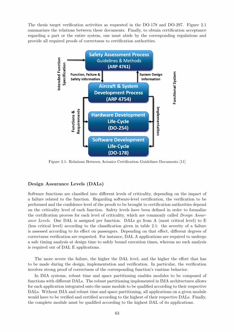
The thesis target verification activities as requested in the DO-178 and DO-297. Figure 2.1summarizes the relations between these documents. Finally, to obtain certification acceptanceregarding a part or the entire system, one must abide by the corresponding regulations andprovide all required proofs of correctness to certification authorities.
Figure 2.1: Relations Between Avionics Certification Guidelines Documents [11]
Design Assurance Levels (DALs)
Software functions are classified into different levels of criticality, depending on the impact ofa failure related to the function. Regarding software-level certification, the verification to beperformed and the confidence level of the proofs to be brought to certification authorities dependon the criticality level of each function. Safety levels have been defined in order to formalizethe certification process for each level of criticality, which are commonly called Design Assur-ance Levels. One DAL is assigned per function. DALs go from A (most critical level) to E(less critical level) according to the classification given in table 2.1: the severity of a failureis assessed according to its effect on passengers. Depending on that effect, different degrees ofcorrectness verification are requested. For instance, DAL A applications are required to undergoa safe timing analysis at design time to safely bound execution times, whereas no such analysisis required out of DAL E applications.
The more severe the failure, the higher the DAL level, and the higher the effort that hasto be made during the design, implementation and verification. In particular, the verificationinvolves strong proof of correctness of the corresponding function’s runtime behavior.
In IMA systems, robust time and space partitioning enables modules to be composed offunctions with different DALs. The robust partitioning implemented in IMA architectures allowsfor each application integrated onto the same module to be qualified according to their respectiveDALs. Without IMA and robust time and space partitioning, all applications on a given modulewould have to be verified and certified according to the highest of their respective DALs. Finally,the complete module must be qualified according to the highest DAL of its applications.
63
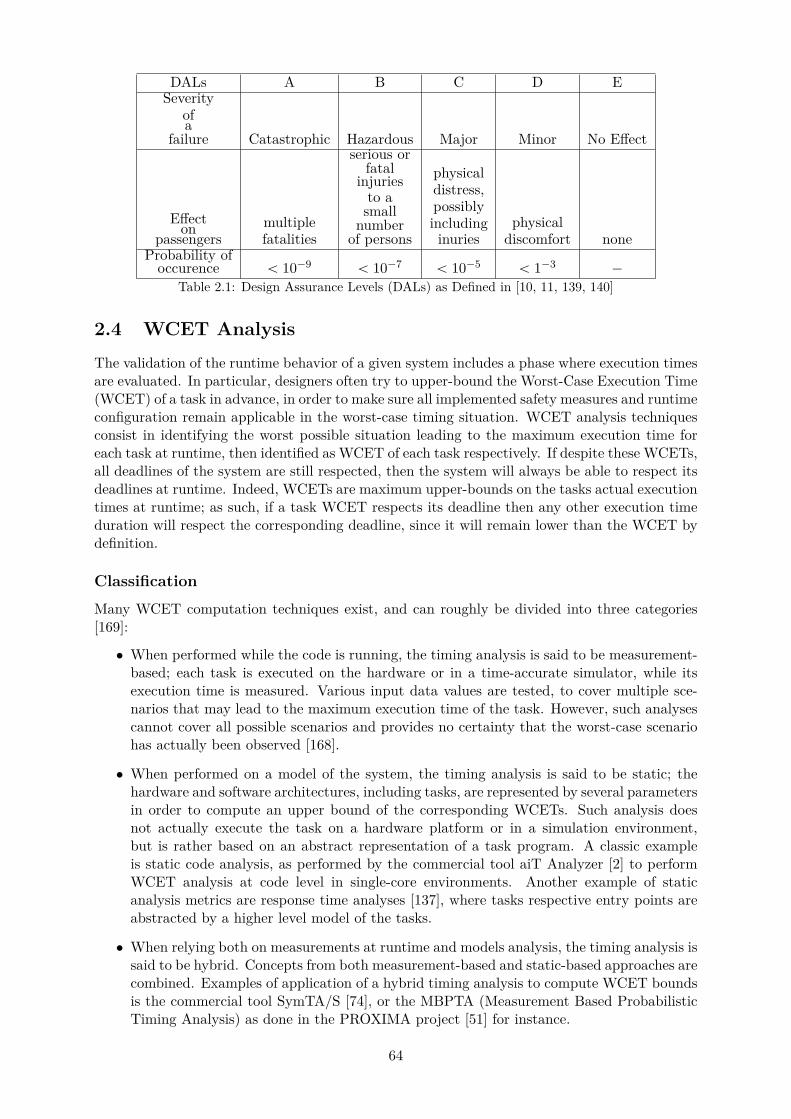
DALs A B C D ESeverity
ofa
failure Catastrophic Hazardous Major Minor No Effect
Effecton
passengersmultiplefatalities
serious orfatal
injuriesto a
smallnumber
of persons
physicaldistress,possiblyincluding
inuriesphysical
discomfort noneProbability of
occurence ă 10´9 ă 10´7 ă 10´5 ă 1´3 ´
Table 2.1: Design Assurance Levels (DALs) as Defined in [10, 11, 139, 140]
2.4 WCET Analysis
The validation of the runtime behavior of a given system includes a phase where execution timesare evaluated. In particular, designers often try to upper-bound the Worst-Case Execution Time(WCET) of a task in advance, in order to make sure all implemented safety measures and runtimeconfiguration remain applicable in the worst-case timing situation. WCET analysis techniquesconsist in identifying the worst possible situation leading to the maximum execution time foreach task at runtime, then identified as WCET of each task respectively. If despite these WCETs,all deadlines of the system are still respected, then the system will always be able to respect itsdeadlines at runtime. Indeed, WCETs are maximum upper-bounds on the tasks actual executiontimes at runtime; as such, if a task WCET respects its deadline then any other execution timeduration will respect the corresponding deadline, since it will remain lower than the WCET bydefinition.
Classification
Many WCET computation techniques exist, and can roughly be divided into three categories[169]:
• When performed while the code is running, the timing analysis is said to be measurement-based; each task is executed on the hardware or in a time-accurate simulator, while itsexecution time is measured. Various input data values are tested, to cover multiple sce-narios that may lead to the maximum execution time of the task. However, such analysescannot cover all possible scenarios and provides no certainty that the worst-case scenariohas actually been observed [168].
• When performed on a model of the system, the timing analysis is said to be static; thehardware and software architectures, including tasks, are represented by several parametersin order to compute an upper bound of the corresponding WCETs. Such analysis doesnot actually execute the task on a hardware platform or in a simulation environment,but is rather based on an abstract representation of a task program. A classic exampleis static code analysis, as performed by the commercial tool aiT Analyzer [2] to performWCET analysis at code level in single-core environments. Another example of staticanalysis metrics are response time analyses [137], where tasks respective entry points areabstracted by a higher level model of the tasks.
• When relying both on measurements at runtime and models analysis, the timing analysis issaid to be hybrid. Concepts from both measurement-based and static-based approaches arecombined. Examples of application of a hybrid timing analysis to compute WCET boundsis the commercial tool SymTA/S [74], or the MBPTA (Measurement Based ProbabilisticTiming Analysis) as done in the PROXIMA project [51] for instance.
64

Figure 2.2: Execution Times Distribution for a given Task [169]
Figure 2.2 illustrates the distribution of execution times that can be observed for a giventask at runtime, the corresponding real WCET, and the WCET bounds computed using a statictiming analysis. Static analyses are safe in the sense that they produce upper-bounds on theexecution time that are guaranteed to never be exceeded at runtime, since all possible inputdata values of the task are considered during analysis.
A static analysis covers all possible traces of execution that could happen at runtime, withoutactually needing the system to run in order to do so. These analyses are usually focused onidentifying the worst-case runtime scenario, in order to produce a maximum upper-bound ofthe WCET of the given task, which will then correspond to a maximum upper-bound that isapplicable to absolutely all situations that can happen at runtime for that task.
The static timing analysis is the only method that guarantees safe WCET estimates. Measurement-based and hybrid techniques are usually less complex than static techniques. However, theproduced upper-bounds are not ensured to be safe since there is no proof that the actual worst-case runtime situation has effectively been observed and therefore that the corresponding actualWCET has indeed been measured. As such, as illustrated in figure 2.2, only static timing analysistechniques can be considered as producing safe WCET upper-bounds for certification authorities.
Moreover, static analysis techniques are considered formal proofs of correctness for certifica-tion authorities since they are focused on exhaustive analyses based on the worst-case situation.However, such analyses inevitably produce pessimistic timing upper-bounds, as the consideredworst-case actually corresponds to a situation that is always worse than the actual worst-casesituation that could happen at runtime. As illustrated in figure 2.2, the corresponding pessimismcorresponds to the difference between the maximum WCET bound produced using static timinganalysis and the actual WCET. On the other hand, pessimistic predictions are not prohibitivefor the aerospace industry. In fact, the embedded pessimism can be seen as additional safetymargins added to the computed WCET upper-bounds, provided that tasks are forced to holdthe CPU until the end of the duration of the corresponding pessimistic bound computed by theanalysis, even if their real execution finishes earlier. Safety margin is a concept commonly ac-cepted in the aerospace industry, who would rather work with slow designs embedding too largesafety margins but which runtime behavior is deterministic, rather than with highly optimizedbut non-deterministic systems.
Eventually, for a given static analysis technique, if the embedded pessimism is too impor-tant, the resulting schedules built using the corresponding WCET upper-bounds lead to CPUunder-utilization at runtime. The consequence is the design of systems embedding much morehardware modules than could have been achieved if the WCET bounds were less pessimistic.As such, even though pessimism is tolerated, the WCET upper-bounds produced by a staticanalysis should be as close to the real WCET as possible. This is also referred to as tightnessof the analysis.
65

Because aircraft certification is the main challenge of the present work, this thesis is focusedon static timing analyses. As such, the rest of this chapter will be focused on presenting themain static timing analysis techniques of the literature that are commonly used in single-coreenvironments.
Code Analysis
Static WCET analysis at code level derives its timing information from the analysis of thecorresponding program code, while using abstract models of the hardware architecture. Unlikethe measurement-based and hybrid timing analysis approaches, static code analysis performs anexhaustive analysis of all possible input values to single out the longest control flow path of theprogram leading to the maximum execution time. The control flow graph of a program is usuallybuilt on the assembly or machine level of the code, in order to represent low level instructionsindividually and give them a corresponding maximal execution time duration. Basic blocks ofinstructions are identified, as a maximal sequence of instructions that can be entered and exitedonly at the first and the last instruction respectively. To construct the corresponding controlflow graph, the program is identified as a set of connections between these basic blocks, in whicheach end-to-end path corresponds to a possible execution trace at runtime.
The efficiency and reliability of WCETs produced by a static analysis highly depend onthe abstract models used to represent the hardware platform. The more detailed the hardwaremodel, the more accurate – and thus, the less pessimistic – the produced WCET upper-bounds.However, the price to pay for a detailed hardware model and accurate WCET bounds is unre-alistic analysis times due to the complexity of programs to analyze and exponential numbersof state spaces to evaluate when exploring programs control flow graphs. In general, the levelof abstraction of the system model influences the tightness and quality of the produced WCETbounds.
Scheduling Theory
Figure 2.3: Classic Task Model [105]
Real-time software applications are often assimilated to a set of periodic tasks, which interactin real-time according to their environment. Tasks have temporal constraints, often representedas a certain amount of time within which they respectively must have completed their executionin order to ensure a correct runtime behavior of the resulting system. As such, Liu and Layland[105] proposed to represent a task τi as: an execution duration Ci; a relative deadline Di
corresponding to the amount of time it has from the moment it started running to complete itsexecution; and a period Ti corresponding to the time interval between two successive activationsof the task. A simplified representation of such a task model is given in figure 2.3. In this model,Ci represents the maximum amount of time for a processing resource to execute the softwarecode – also called entry point – of a task τi in isolation, i.e. when τi has exclusive access to allresources necessary to its execution. Ci is also referred to as execution duration in isolation
66
in the literature as well as in this thesis. It is important to note that Ci is not the WCET of τiin a multicore environment, but rather a single-core environment. In this thesis, in a multicoreenvironment, the WCET includes environment-related delays, such as intercore interference forinstance.
From the point of view of a processing resource, a task τi represents a workload of ui “ CiTi
.The task τi requires to be scheduled every Ti time units, i.e. a task wakes up every Ti timeunits. When a task is selected by the OS to be scheduled on a given processing resource, thetask is said to be activated.
An execution of a task is often referred to as instance. For a given task instance, theresponse time refers to the time duration elapsed from the moment the instance awakes, tothe end of execution of the instance. The Worst-Case Response Time (WCRT) of a taskτi is the biggest response time of all its instances; it is denoted Ri in the scheduling theory, aswell as in this thesis. A task is then said to be schedulable if and only if all instances of thattask are able to complete their execution within the deadline limitation, i.e. if Ri ď Di. A setof tasks is said to be schedulable if all tasks are schedulable.
In the scheduling theory, two types of analysis can be identified: feasibility analyses, andschedulability analyses. Both analyses view a task according to its runtime behavior in orderto determine whether the task will always have enough processing resource to be executed asexpected according to a behavior predefined during application design. These analyses belongto the scheduling theory, and abstract a task code by only representing the task according toruntime parameters such as priority level or periodicity for instance [105].
Feasibility Analysis A feasibility analysis focuses on determining whether a set of tasks,given a scheduling algorithm, can be scheduled on a given processing resource without any taskmissing some deadline at runtime.
In fact, feasibility analyses can be used in advance to help setting design choices such asdeciding which tasks will be executed on which processing resources for instance; it identifieswhich combinations of task-to-processing resource allocation will lead to systems where sometasks cannot respect their deadlines for instance. Scheduling analyses are performed once a task-to-processing resource allocation choice has been made and once a schedule has been staticallyset for each processing resource.
Three main techniques exist to perform a feasibility analysis:
• processor utilization analysis, relying on the computation of a processing resource utiliza-tion or workload,
nTř
i“1
CiTi
where nT is the number of tasks executing on that processing
resource. If the total workload of a task set on a given processing resource remains smallerthan a certain value depending on the scheduling policy, the system is ensured to beschedulable.
• processor demand analysis, in which the cumulated sum of executions of task instances in agiven time interval on a processing resource is computed. The resulting function dependingon the considered time interval is called the demand bound function, and is plotted in orderto verify that it always remains under the curve of the corresponding processor availabilityfunction.
• response time analysis, which determines the WCRT for each task Ri and compare themwith the corresponding deadline Di to check whether all deadlines can still be enforced atruntime despite the worst-case scenario.
While the first two techniques analyze busy periods of a processing resource, the third ap-proach implicitly leads to the computation of an upper-bound of tasks WCRTs including block-ing times due to potential runtime overheads and dependencies between tasks. One of the maincontribution of this thesis is to propose a response time analysis fit for IMA architectures and
67
multicore platforms. As such, the next section of this chapter will be focused on defining ingreater details the response time analysis.
Scheduling analysis Compared to code-level WCET analyses, the primary goal of schedula-bility analyses is to assess beforehand whether a task will always be able to respect its timingrequirements at runtime. In fact, part of validating real-time systems consists in proving that alltasks of the system respect their deadlines and other timing-related constraints such as commu-nications and synchronizations for instance. Finally, an analysis performed in order to evaluatethe possibility that all tasks will do so when using a given processing resource is called feasibilityanalysis. An analysis performed on a given schedule for a given task set and processing resourcesis called schedulability analysis. Both analysis metrics belong to the scheduling theory.
2.5 Response Time Analysis
This subsection presents the necessary background knowledge to understand the task-level tim-ing analysis approach presented in this thesis. Every aspect of the analysis presented in thissubsection presents models of the scheduling theory as currently commonly admitted among thereal-time community; as such, it is important to keep in mind that none of the aspects presentedin this subsection is intended for – and as such, applicable to – IMA architectures nor multicoreprocessing resources.
Classic definitions of the response time analysis are given for software functions defined asa set of tasks only, with no representation or any equivalent of the partition level that existsin IMA architectures. As mentioned earlier, the adaptation of the techniques presented in thissubsection to IMA architectures is in fact one of the contributions of this thesis, as will bepresented in chapter 5.
In the rest of this section, the words ”processing resource or ”processor” are used to refer toan environment consisting in one single-core processor. Finally, the response time analysis willfirst be presented for preemptive task sets, and later on for non-preemptive task sets.
Classic Response Time Analysis
The response time analysis is a static analysis focused on determining whether the WCRT of atask τi, denoted Ri, is smaller than the corresponding task deadline, denoted Di. The worst-case situation being considered to be the one leading to the longest response times, Ri is alsooften assimilated to an upper-bound on all possible values of τi response time that can occurat runtime. As a consequence, if Ri is smaller than Di, then all other response times will besmaller than Di as well. The response time analysis is therefore said to be a sufficient conditionof schedulability for a given task set.
In order to understand how Ri is computed for each task τi, it is necessary to introduce thenotion of busy period for a given processing resource.
In this thesis, all tasks are periodic. As such, two successive executions of a task occuraccording to its period. When scheduling a set of periodic tasks on a given processing resource,there exists a pattern of execution that is repeated infinitely at runtime. The smallest patternrepeated over time corresponds to a time interval called hyperperiod. In order to verify if asystem respects all its deadlines at runtime, it suffices to perform a timing analysis on onehyperperiod in order to cover the entire runtime behavior of the corresponding system. As such,the hyperperiod is also sometimes referred to as feasibility interval. The length of the feasibilityinterval corresponds to the Least Common Multiple (LCM) of the tasks periods.
Within the hyperperiod, time intervals where the processing resource is busy executing oneof the tasks are analyzed. More specifically, in order to consider the worst-case situation, thenotion of busy period for a given processor has been introduced, as a time interval in which the
68
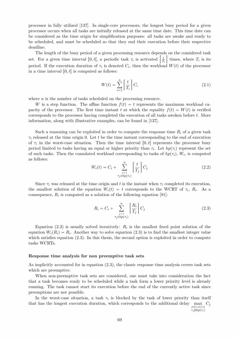
processor in fully utilized [137]. In single-core processors, the longest busy period for a givenprocessor occurs when all tasks are initially released at the same time date. This time date canbe considered as the time origin for simplification purposes: all tasks are awake and ready tobe scheduled, and must be scheduled so that they end their execution before their respectivedeadline.
The length of the busy period of a given processing resource depends on the considered taskset. For a given time interval r0, tr, a periodic task τi is activated
Q
tTi
U
times, where Ti is itsperiod. If the execution duration of τi is denoted Ci, then the workload W ptq of the processorin a time interval r0, tr is computed as follows:
W ptq “nÿ
i“1
R
t
Ti
V
Ci (2.1)
where n is the number of tasks scheduled on the processing resource.W is a step function. The affine function fptq “ t represents the maximum workload ca-
pacity of the processor. The first time instant t at which the equality fptq “ W ptq is verifiedcorresponds to the processor having completed the execution of all tasks awoken before t. Moreinformation, along with illustrative examples, can be found in [137].
Such a reasoning can be exploited in order to compute the response time Ri of a given taskτi released at the time origin 0. Let t be the time instant corresponding to the end of executionof τi in the worst-case situation. Then the time interval r0, tr represents the processor busyperiod limited to tasks having an equal or higher priority than τi. Let hppτiq represent the setof such tasks. Then the cumulated workload corresponding to tasks of hppτiq, Wi, is computedas follows:
Wiptq “ Ci `nÿ
j“1τjPhppτiq
R
t
Tj
V
Cj (2.2)
Since τi was released at the time origin and t is the instant when τi completed its execution,the smallest solution of the equation Wiptq “ t corresponds to the WCRT of τi, Ri. As aconsequence, Ri is computed as a solution of the following equation [81]:
Ri “ Ci `nÿ
j“1τjPhppτiq
R
RiTj
V
Cj (2.3)
Equation (2.3) is usually solved iteratively: Ri is the smallest fixed point solution of theequation WipRiq “ Ri. Another way to solve equation (2.3) is to find the smallest integer valuewhich satisfies equation (2.3). In this thesis, the second option is exploited in order to computetasks WCRTs.
Response time analysis for non preemptive task sets
As implicitly accounted for in equation (2.3), the classic response time analysis covers task setswhich are preemptive.
When non-preemptive task sets are considered, one must take into consideration the factthat a task becomes ready to be scheduled while a task form a lower priority level is alreadyrunning. The task cannot start its execution before the end of the currently active task sincepreemptions are not possible.
In the worst-case situation, a task τi is blocked by the task of lower priority than itselfthat has the longest execution duration, which corresponds to the additional delay max
jPr1;nsztiuτjRhppτiq
Cj
69
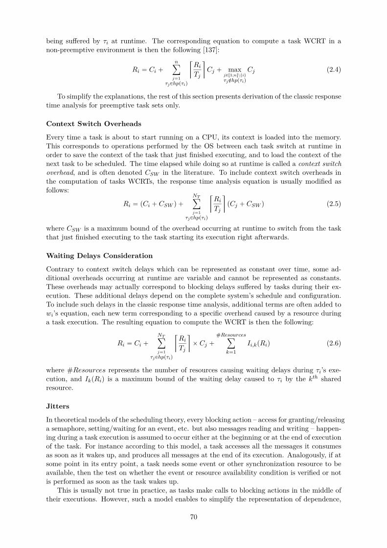
being suffered by τi at runtime. The corresponding equation to compute a task WCRT in anon-preemptive environment is then the following [137]:
Ri “ Ci `nÿ
j“1τjPhppτiq
R
RiTj
V
Cj ` maxjPr1;nsztiuτjRhppτiq
Cj (2.4)
To simplify the explanations, the rest of this section presents derivation of the classic responsetime analysis for preemptive task sets only.
Context Switch Overheads
Every time a task is about to start running on a CPU, its context is loaded into the memory.This corresponds to operations performed by the OS between each task switch at runtime inorder to save the context of the task that just finished executing, and to load the context of thenext task to be scheduled. The time elapsed while doing so at runtime is called a context switchoverhead, and is often denoted CSW in the literature. To include context switch overheads inthe computation of tasks WCRTs, the response time analysis equation is usually modified asfollows:
Ri “ pCi ` CSW q `NTÿ
j“1τjPhppτiq
R
RiTj
V
pCj ` CSW q (2.5)
where CSW is a maximum bound of the overhead occurring at runtime to switch from the taskthat just finished executing to the task starting its execution right afterwards.
Waiting Delays Consideration
Contrary to context switch delays which can be represented as constant over time, some ad-ditional overheads occurring at runtime are variable and cannot be represented as constants.These overheads may actually correspond to blocking delays suffered by tasks during their ex-ecution. These additional delays depend on the complete system’s schedule and configuration.To include such delays in the classic response time analysis, additional terms are often added towi’s equation, each new term corresponding to a specific overhead caused by a resource duringa task execution. The resulting equation to compute the WCRT is then the following:
Ri “ Ci `NTÿ
j“1τjPhppτiq
R
RiTj
V
ˆ Cj `#Resources
ÿ
k“1Ii,kpRiq (2.6)
where #Resources represents the number of resources causing waiting delays during τi’s exe-cution, and IkpRiq is a maximum bound of the waiting delay caused to τi by the kth sharedresource.
Jitters
In theoretical models of the scheduling theory, every blocking action – access for granting/releasinga semaphore, setting/waiting for an event, etc. but also messages reading and writing – happen-ing during a task execution is assumed to occur either at the beginning or at the end of executionof the task. For instance according to this model, a task accesses all the messages it consumesas soon as it wakes up, and produces all messages at the end of its execution. Analogously, if atsome point in its entry point, a task needs some event or other synchronization resource to beavailable, then the test on whether the event or resource availability condition is verified or notis performed as soon as the task wakes up.
This is usually not true in practice, as tasks make calls to blocking actions in the middle oftheir executions. However, such a model enables to simplify the representation of dependence,
70
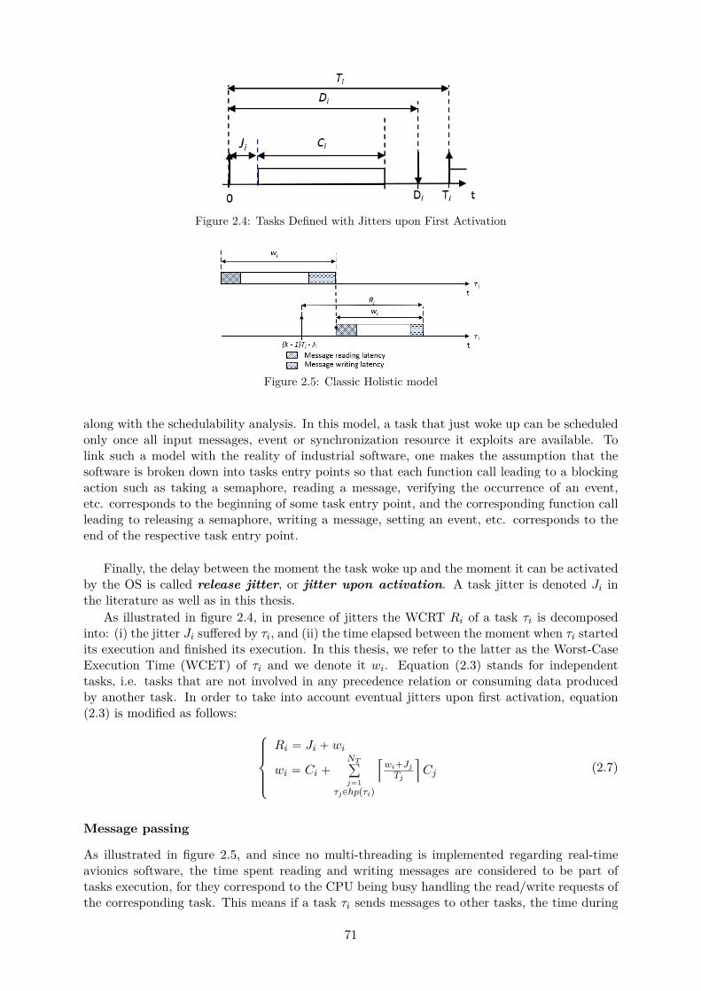
Figure 2.4: Tasks Defined with Jitters upon First Activation
Figure 2.5: Classic Holistic model
along with the schedulability analysis. In this model, a task that just woke up can be scheduledonly once all input messages, event or synchronization resource it exploits are available. Tolink such a model with the reality of industrial software, one makes the assumption that thesoftware is broken down into tasks entry points so that each function call leading to a blockingaction such as taking a semaphore, reading a message, verifying the occurrence of an event,etc. corresponds to the beginning of some task entry point, and the corresponding function callleading to releasing a semaphore, writing a message, setting an event, etc. corresponds to theend of the respective task entry point.
Finally, the delay between the moment the task woke up and the moment it can be activatedby the OS is called release jitter, or jitter upon activation. A task jitter is denoted Ji inthe literature as well as in this thesis.
As illustrated in figure 2.4, in presence of jitters the WCRT Ri of a task τi is decomposedinto: (i) the jitter Ji suffered by τi, and (ii) the time elapsed between the moment when τi startedits execution and finished its execution. In this thesis, we refer to the latter as the Worst-CaseExecution Time (WCET) of τi and we denote it wi. Equation (2.3) stands for independenttasks, i.e. tasks that are not involved in any precedence relation or consuming data producedby another task. In order to take into account eventual jitters upon first activation, equation(2.3) is modified as follows:
$
’
’
&
’
’
%
Ri “ Ji ` wi
wi “ Ci `NTř
j“1τjPhppτiq
Q
wi`JjTj
U
Cj (2.7)
Message passing
As illustrated in figure 2.5, and since no multi-threading is implemented regarding real-timeavionics software, the time spent reading and writing messages are considered to be part oftasks execution, for they correspond to the CPU being busy handling the read/write requests ofthe corresponding task. This means if a task τi sends messages to other tasks, the time during
71
which each message is written at runtime is considered to be a part of the task execution time.As a consequence, a task execution time now includes two additional durations:
• The time needed by τi to read all messages it receives, msgsreadi;
• The time needed by τi to write all messages it sends, msgswritei.
where msgsreadi and msgswritei compute the corresponding interference delay when τi respec-tively reads/writes its messages in the main memory. To our knowledge, no particular modelof the msgsreadi and msgswritei functions respectively have been commonly admitted by thecommunity as of today.
In scheduling theory, these two durations are added to the tasks response times according tothe classic holistic model illustrated in figure 2.5: for all messages, the reading phase happensat the beginning of each task, and the writing at the end of each task. To match such a model,wi’s equation can be updated as follows:
wi “ msgsreadi
`
¨
˚
˚
˚
˚
˝
Ci `NTř
j“1τjPpartpiq
τjPhppτiq
Q
wi`JjTj
U
Cj `#Resources
ř
k“1Ii,kpwiq
˛
‹
‹
‹
‹
‚
`msgswritei
(2.8)
where the term in parentheses corresponds to the right-hand side of wi’s equation; the first andthe third term respectively refer to the duration of the reading and the writing phases describedin the previous paragraphs.
2.6 Summary
In this chapter, we presented the background knowledge required to understand the extent of ourcontributions. The chapter began with a definition of the main general terms employed through-out this thesis, before presenting the basis of IMA and certification concerns in the aerospacesystems design life cycle. A classification of existing timing analysis for WCET computationhas then been given, with special attention to static techniques since it is at the core of thecontributions of this thesis. The chapter then concludes with the current summary.
72
Chapter 3
State of the Art
The multicore challenge has been around for several years. Many works thoroughly studied theorigin of the difficulty of performing safe WCET analysis when using complex multicore hardwarearchitectures such as current COTS. As a consequence, many different approaches were takenin order to tackle the multicore challenges at hand. This chapter presents the related work ofthe literature dealing with the challenges brought by multicores in hard-real-time systems.
3.1 Overview
The multicore problem is vast and multifold. Resource sharing coupled with non deterministicarchitectures and arbitration policies result in difficulties to predict safe WCET upper bounds.Multiple roles and industries involved in hard real-time systems design are impacted, from thesoftware developer to the manufacturer, the system designer to the provider of RTOS. As such,there exists more than one potential approach to tackle the multicore challenge.
This chapter is an attempt at presenting an overview of the literature related to the multicorechallenge addressed in this thesis, i.e. allocating, scheduling and performing timing analysis onmulticore platforms for hard real-time systems. Related works are roughly classified according tothe approach chosen by the respective authors. Each identified category of approach is presentedin a dedicated section. Categories remotely related to- but not in the scope of this thesis arebriefly presented as well. A brief statement is given at the end of each section to compare withthe scope of this thesis.
3.2 Execution Models
When dealing with multicores, some works of the literature propose to control the access toshared resources in a multicore platform by redesigning tasks software into several pieces ofsoftware explicitly separating shared resource access phases and non-access phases. The goalis to compute interference-free schedules by never overlapping shared resource access phases oftwo active tasks on different cores.
Schranzhofer et al. [151] studied different shared cache accessing models and compared themin terms of schedulability. They draw conclusions in favor of separating resource accesses fromcomputation phases, and consequently propose to use a dedicated access model with superblocksexecuted sequentially.
Pellizzoni et al.[131] proposed the Predictable Execution Model (PREM) as an executionmodel where each task has a data acquisition phase during which data necessary to the taskexecution are fetched either from the memory or from the cache, followed by an execution phase.
Durrieu et al. [58] proposed a similar execution model then exploited to implement a pre-dictable Flight Management System (FMS) on a multicore COTS. The execution model containsthree phases: (i) a resource access phase at the beginning of a task execution in order to fetchall data necessary to its execution; (ii) a pure computation phase during which no access to any
73
shared resource is performed; (iii) and another resource access phase at the end of executionof a task during which all produced and updated data is written back in memory. A scheduleis built so that two resource access phases of two scheduled tasks on two different cores neveroverlap in time, in order to make sure that only one task is accessing a given shared resourceat any given time. These works are later reused in [68] coupled with memory partitioning andstatic scheduling in order to propose a toolchain for a safe and interference free deployment ofavionics applications on multicore systems.
Boniol et al. [32] proposed the same kind of execution models, but considered that multipleresource access phases – interleaved with pure computation phases – can happen throughoutthe execution of a task. The approach also includes cache consideration in order to improvethe determinism of tasks runtime execution. To do so, resource access phases – also referredto as communication phases – are preceded with actions to flush the shared cache and load incache the context of the next task to be scheduled, along with all data it may access in its firstresource access phase.
Kim et al. [87] proposed a similar distinction between resource access and pure computation,but at partition level for IMA systems. In a given partition-level schedule, the time allocated toeach partition is divided into exclusive resource access phases and pure computation phases. Theidentification of such phases is exploited when building a schedule, in order never to scheduletwo resource access phases in overlapping time intervals on two different cores, but allowing”computation” phases to overlap.
Statement
New execution models are very promising for future multicore based systems, as they will enableto fully benefit from the performance gain that can be achieved with multicores. However,proposing new ways for software development exclusively targeting multicore architectures isout of the scope of this thesis, as our goal is to reuse legacy software. Moreover, the proposedexecution models are not mature yet for industrial usage; one of the objectives of this thesis isto propose an approach to enable multicore usage without having to wait for some approachinvolved in the proposed works to be mature enough to be used in the avionics industry. Forthese reasons, new execution models are not further considered in this thesis.
3.3 Dedicated Designs
As mentioned earlier, many different approaches were taken in order to tackle the multicore chal-lenges at hand. Among them, many works of the literature emerged as propositions of predictablemulticore architectures, hardware components, monitoring and/or hypervising frameworks.
Multicore Processor Designs Some proposed custom multicore designs aimed at simplifyingWCET analysis by proposing simpler, white box multicore architectures exploiting predictablearbitration policies and components.
For instance, Edwards and Lee [59] presented an architecture focused on providing repeatabletiming behaviors through constant instruction execution times and programs path balancing.Later on, Zimmer et al. [181] designed a new PRET machine architecture called Flex-PRET formixed criticality systems support. The proposed architecture relies on fine-grained multithread-ing and scratchpad memories in order to provide isolation capabilities for hard real-time taskswhile offering quality of service for soft tasks.
Schoeberl [149] designed ”Patmos”, a java processor architecture for embedded real-timesystems and provides the complete handbook and datasheet of the corresponding architecturein order to enable to perform timing-accurate analysis. The T-CREST European project (2007- 2013) [150] then exploited Patmos in order to build a time-predictable multicore platformguaranteeing predictable and low WCETs for hard real-time systems.
74

The RECOMP (REduced Certification cOst for trusted Multicore Platforms) [133] project(2010 - 2013) targeted the design of a multicore architecture for enabling cost-efficient certifica-tion and re-certification of safety-critical systems.
Similarly, the MERASA (Multicore Execution of parallelized hard Real-time ApplicationssuppoRting Analyzability) [164] project (2007 - 2010) aimed at designing a multicore architecturefitting all hard real-time industrial needs, for usage in avionics, automotive and railway indus-tries. To do so, hardware components showing interesting features for hard real-time systemswere identified first in order to be exploited in the resulting multicore architecture proposed.
The parMERASA (parallelized MERASA) [163] project (2011 - 2014) then started as afollow-up project on MERASA, and was focused on proposing a timing analyzable manycorearchitecture and enabling software parallelization for hard real-time industrial systems.
The PREDATOR (Design for Predictability and Efficiency) [170] project (2008 - 2011) pro-posed a generic methodology of conception fitting industrial requirements by identifying guide-lines for the definition of the hardware platform to be used for hard real-time systems, accordingto the ”architecture follows application” concept.
Hardware Component Designs Other similar works of the literature are focused on propos-ing custom component designs in order to control – or get rid of – interference when accessingshared resources in a multicore platform. The goal of these works is to inspire multicore manu-facturers with designs potentially approved by hard real-time systems industries for their futuremulticore COTS. For instance, Obermaisser and Weber [124] introduced a system model withgateways and end-to-end channels for mixed criticality systems on network-based heterogeneousmulticores. Kim et al. [88] presented an approach for WCET-aware dynamic code managementusing scratchpads for software-managed multicores.
Several works of the literature focused on proposing predictable memory controllers able tomonitor the access to the main memory and enforce a predictable access scheme at runtime[15, 128, 77, 136]. Akesson et al. [15] proposed a predictable SDRAM memory controller namedPredator. The proposed design is capable of enforcing a minimum bus bandwidth, along witha maximum latency for each memory access request generated by the cores of a same multicorethanks to a non-fair arbitration that requires knowledge about requestors. Paolieri et al. [128]proposed an analyzable memory controller that implements fair round robin arbitration. Hassanand Patel [77] presented a criticality-aware bus arbitrator for mixed-criticality systems. Reinekeet al. [136] introduced the PRET DRAM controller, based on memory bank privatization inorder to enforce predictability and temporal isolation at runtime.
Other propositions in the same line of idea focus on finding new arbitration policies for sharedresources requests servicing. For instance several works focused on cache block eviction policies[98, 135, 92, 179], either to minimize tasks interference delays [135] or to prioritize high criticalitytasks resource accesses over non-critical tasks in mixed criticality environments [98, 92, 179].
Interference Monitoring based on Middleware Layers Modifications Some proposeapproaches based on hypervising techniques in order to reduce or get rid of interference whenaccessing shared resources of a multicore processor.
For instance, Liu et al. [107] proposed to suppress memory interference by modifying theOS memory management subsystem; the approach consists in implementing a page coloringbased bank level partition mechanism to allocate specific DRAM banks to specific cores ortasks. Similarly, 2014 Yun et al. [177] proposed a DRAM bank-aware memory allocator namedPALLOC, aiming to achieve resource isolation on multicore platforms. PALLOC relies on cacheand memory partitioning at application-level by allocating memory banks to applications byleveraging the page-based virtual memory system.
Rajkumar et al. [134] proposed a resource kernel for real time resource management formultimedia applications. Jean [80] implemented hypervising techniques for controlling resource
75
accesses by cores in a multicore environment and enforce runtime determinism for future usagein avionics systems. Desenfants et al. [56] presented HIPPEROS, a multicore embedded real-time operating system kernel targeting safe WCET analysis and predictable runtime behavior.The European project MULTIPARTES [162] focused on resource isolation requirements that aremandatory in IMA architectures. Xtratum [180], the outcome of the project, exploits hypervisingand virtual machines concepts in order to isolate clusters of cores and RTOS from each otherso that each cluster can use its own areas of shared resources, the access to which is partitionedand monitored by a hypervising layer at runtime.
Van Kampenhout [165] proposed to create hardware partitions in order to allocate timewindows for the usage of all shared resources to only one software application on the entiremulticore at any given time. To do so, the author proposed to allocate the software partitionsto hardware partitions, and then allocate them on cores.
Nowotsch [122, 123] pre-computed CPU time budgets to be allocated to each task and relieson monitoring techniques to enforce these bounds at runtime. A linear model for computing taskinterference and WCET bounds based on the number of resource access requests is proposed.Any task CPU time budget overrun is prevented at runtime by a hypervising layer that enforcesthe computed time budgets.
Finally, the approach in [111] proposed a single-core equivalence to implement legacy IMAapplications on multicore, but does not offer interference-aware tasks response times computa-tion. Instead, it relies on hardware-specific components to manage a server-based time sharingof applications.
Statement
The proposed architectures are targeting hard real-time systems and therefore usually presentthe main characteristics and safety components traditionally sought out by avionics industriesin hardware platforms. However, although related, such works are not in the scope of this thesis,since the thesis aims at using COTS multicores.
The same statement can be made about the propositions of custom hardware componentsdesigns or requests arbitration policies. These works would require multicore and/or RTOSmanufacturers to implement them in their designs in order for the corresponding works to beexploitable. For these reasons, dedicated designs are not further considered in this thesis.
3.4 Software-Based Resource Access Monitoring Approaches
Aside from dedicated designs, other works propose to control (monitor or limit) the resourceaccesses times or impose budgets for each resource and each application. To do so, such ap-proaches rely either on specific scheduling policies, or on specific, custom hardware features.The difference with works presented in the previous section is that they rely on hardware orhypervising features that are either currently available in current COTS, or assume they will bein future COTS; they are focused on proposing a way to use them, and not a way to actuallyimplement them, contrary to the previous section.
The goal of these works is not to characterize but rather get rid of multicore-induced in-terference, so that single-core analysis techniques can be exploited. The proposed works oftenconsist in restricting access to shared resources, either physically (partitioned space allocationfor instance), temporally (by controlling when a core can access a specific resource for instance),or both.
Several works proposing resource access monitoring techniques target shared cache usage inmulticores [86, 20, 161, 42]. Kim et al. [86] proposed to partition the cache and main memoryaccordingly in order for the entire memory hirerarchy to be partitioned at task-level. To do so,the approach relies on OS-level cache management capabilities. An algorithm for finding the
76
best task-to-core allocation regarding the minimization of core utilization is then proposed. Theapproach proposes a static model for intra-core cache interference, including warm-up delaysand preemption-induced delays. The resulting delays are then included in a sufficient conditionof schedulability according in a fixed priority preemptive context, either based on utilizationbounds or response time analysis.
Altmeyer et al. [20] presented an algorithm to find the best task level cache partitioning con-figuration for which the existence of a feasible schedule is guaranteed. The proposed algorithmis based on the branch and bound heuristic, and takes a schedule as input. Tasks sensitivity toeach cache partitioning configuration is taken into account depending on the size of the cachepartition.
Tan and Mooney [161] claimed to be the first ones to link tasks priorities with cache linesusage. Each cache line is assigned a priority, and a task can use all cache lines with a priorityequal or lower than the task priority. They propose a cache controller in order to dynamicallymonitor the priority and usage of each cache line.
Chisholm et al. [42] proposed criticality-aware optimization techniques for last level sharedcache areas allocation to mixed criticality software systems allowing for schedulability improve-ment in multicore environments.
Suhendra and Mitra [159] proposed to combine cache partitioning and locking in order tocope with the problem of interference characterization in WCET analysis. The final goal of theapproach is to achieve predictable L2 cache configuration and performance preservation. To doso, all levels of partitioning (none, core-level, task-level) have been evaluated for comparisonpurposes, both with and without cache locking (dynamic or static).
Resource monitoring techniques were also proposed for bus requests arbitration, in orderto separate each core access to the shared interconnect and therefore to get rid of inter-taskinterference at runtime [138, 43, 36, 47, 48, 50].
Rosen et al. [138] presented an approach for bus access optimization for TDMA bus-basedmutlicore platforms. A TDMA schedule is generated regulating the time intervals within whicheach core is allowed to generate requests to the bus; for a given TDMA schedule, the resultingadditional delays caused by cache misses are evaluated and used as feedback to refine the TDMAschedule. Another implementation of TDMA-based bus requests scheduling is presented by Cilkuet al. [43].
Similarly to [138], Burgio et al. [36] proposed an adaptive TDMA bus allocation and elasticscheduling, the elasticity characteristic being due to the fact that tasks periods are variable.The approach focuses on finding the best set of periodicities leading to a schedulable system onmulticore.
Dasari et al. [47, 48, 50] proposed a response time analysis considering the contention ofthe shared memory bus based on simulating the distribution of tasks requests to the front-sidebus. Observation points are included in tasks codes in order to check the number of cachemisses that occurred up to these corresponding points, and the corresponding tasks WCETs areprogressively increased depending on the requests emitted on other cores that are potentiallyinterfering at runtime, according to a custom algorithm. Once WCETs stopped increasing, thealgorithm performs a timing analysis to check the feasibility of the system.
Finally, another class of related works proposing resource monitoring tries to consider morethan one multicore shared resource at a time. For instance, Yoon et al. [176] proposed tomonitor both cache and bus access, along with computing a TDMA bus schedule, in order tooptimize performance. Their approach determines the optimal allocation and scheduling of taskson cores, bus and cache of a multicore platform; they then propose a WCET analysis based onthe knowledge of the implemented TDMA bus schedule.
77
Statement
These works cope with the difficulty of modeling interference in multicore systems by controllingresource access, for example by identifying time windows during which each core is allowed accessto the corresponding resource. Although such techniques are very interesting, their applicationto an avionics system depends on the existence of a firmware layer with such capabilities. COTSRTOS and multicores usually do not propose such monitoring capabilities, and any custom layeradded to a design must undergo an additional certification acceptance process, which implies anextension of the time-to-market of the system to be designed. As such, the type of approachespresented in this section are not further investigated in this thesis.
3.5 Mixed Criticality Approaches
Some work of the literature came up with new task models distinguishing soft real-time tasksfrom hard real-time tasks, and building systems where hard real-time tasks are prioritized oversoft real-time tasks so that (i) no critical task suffers any deadline miss, and (ii) soft tasks arescheduled as best as possible given the time left after safely scheduling critical tasks.
To the best of our knowledge, [166] was the first to propose to rename as ”mixed criticalitysystems”, systems where some applications were prioritized over others according to criticalitylevels. Since Vestal, the expression ”mixed criticality systems” is employed whenever tasks orapplications of different criticality levels are integrated onto the same hardware platform, anda distinction is made between critical and non-critical applications when performing schedulinganalysis and/or generation.
An overview of the research on the topic of mixed criticality systems has been written byBurns and Davis [37], covering the period since Vestal’s paper up to – and including – july2016. In particular relatively to multicores and allocation/scheduling concerns, the first paperaddressing mixed criticality in multiprocessor environments was by Anderson et al. [21] accord-ing to [37]. Anderson et al. [21] proposed to use slack times not exploited at runtime by highcriticality tasks for increasing quality of service of low criticality tasks. To do so, the authorsproposed five levels of criticality matching the DALs of avionics systems, to which they assigneda separate scheduling policy. Applications with the highest criticality level (corresponding toDAL A applications) are scheduled statically, contrary to applications of all other criticality lev-els: DAL B applications are scheduled using preemptive EDF, DAL C and D global preemptiveEDF and DAL E global best-effort. Each core is expected to have its own hierarchical schedulerimplementation, and slack times are allowed to be passed along to other servers. Such an ap-proach of slack reuse by other servers was then followed by several other works of the literature[21, 115, 72, 71].
Another line of works using the mixed criticality model propose to compute an offline sched-ule with arbitrary WCETs, and dynamically perform changes to that schedule depending onruntime outcomes [99, 67, 31, 91, 156]. Li et al. [99] proposed to exploit global schedulingpolicies and migration capabilities in order to schedule mixed criticality tasks on homogeneousmultiprocessors.
Bletsas and Petters [31] addressed semi-partitioned scheduling, i.e. proposed a mix of parti-tioned and global scheduling within the same multicore processor.
Kritikakou et al. [91] relied on runtime monitoring to dynamically adapt a scheduling plan,thanks to regular comparisons of the remaining time available for each task before its deadline,and its theoretical remaining execution time required to finish, computed in isolation at obser-vation points. High criticality tasks execution times are therefore monitored at runtime in orderto identify when no further interference can be tolerated by the task; when it is the case, lowcriticality tasks running in parallel with the high criticality task are aborted until the lattercompletes its execution. Socci et al. [156] later extended the approach in [91] in order to take
78

into account precedence constraints between task instances.
Some other works propose to build offline schedules depending on tasks respective criticalitylevels [67, 160, 70, 82, 79]. For instance, Giannopoulou et al. [67] exploited model checkingtechniques to generate a reliable schedule, and thus safe bounds on tasks worst-case interference.
Selicean and Pop [160] proposed an approach for the generation of an allocation and a sched-ule for applications on a multicore platform. Tasks are allocated to partitions first, which arethen allocated to cores and scheduled. Tasks of different SILs (criticality levels for automotivesystems) cannot be allocated to the same application, for reduction of certification costs pur-poses. For the same reason, partitions having different SILs cannot be allocated to the samecore. System designers have the possibility to control part of the task-to-partition allocation,by defining mutual exclusion constraints between tasks of the same SIL, or by asking for sometask to be allocated to a partition of a higher SIL. Finally, tabu search is used for the allocation,and list scheduling techniques are exploited to buid offline schedules.
Kelly et al. [82] proposed a SIL-dependent WCET analysis technique, while Goswami et al.[70] proposed an Integer Linear Programming (ILP) algorithm to generate schedules for CPUtime usage by tasks but also bus accesses in order to optimize runtime performance.
Huang et al. [79] proposed to derive mutual exclusion constraints on tasks depending ontheir criticality, to be applied when scheduling the corresponding tasks.To do so, the authorspropose to group tasks in classes according to mutual exclusion constraints, so that mutuallyexclusive tasks are never scheduled in overlapping time intervals in the same multicore.
Other mixed criticality related works proposed to generate more than one schedule offlineand perform mode changes online depending on runtime performances [53, 54, 26]. For instance,Cortes et al. [45] proposed to compute several schedules offline, and activate one of them onlinedepending on when tasks finish their executions at runtime. The selection of schedules is doneso that no deadline of any hard real-time task is missed, and the minimum possible number ofdeadlines of soft-real time tasks are missed. The same concept is later implemented by Saraswatet al. [143] using a constant bandwidth server, the capacity of which is optimized in order tomaximize the quality of service of the soft tasks.
De Niz et al. [53, 54] proposed an algorithm for optimal generation of multi-modal mixed-criticality schedules on multiprocessor platforms. The approach first exploits an algorithm forthe allocation of tasks to cores based on a derivation of bin-packing problem, called ”vectormixed-criticality packing algorithm” (vMCP). A second algorithm of schedule generation basedon the rate monotonic policy is then used, called ”Zero Slack Rate Monotonic” (ZSRM) andwhich includes mode commutation capabilities; however, no interference consideration is madein the proposed approach.
Baruah and Fohler [26] proposed to generate multiple schedules for mixed criticality sys-tems; one schedule is computed as if all tasks were hard real-time tasks and corresponds to theschedule to be shown to certification authorities at design time for certification acceptance. Allother schedules are less pessimistic and correspond to ”engineering modes”: at runtime, one ofthese secondary schedules is exploited, and as soon as a low criticality task overruns its WCET,a mode change is triggered in order to switch to the certification schedule.
Finally, another remarkable line of works proposed to search for the best priority levelsassignment to tasks in mixed criticality systems so that the overall system is feasible on a givenhardware platform [27, 148]. Baruah et al. [27] proposed a response time analysis for mixedcriticality systems coupled with a smart selection of tasks priorities depending on their respectivecriticality levels.
Schneider et al. [148] proposed an offline priority assignment algorithm using an ILP formu-lation before generating schedules for mixed criticality applications on multicores, and is focusedon QoC-oriented efficiency for cyber-physical systems.
79
Statement Mixed criticality techniques take advantage from breaking down tasks accordingto their criticality level in order to secure high criticality tasks execution over low criticalitytasks, the mixed criticality concept did not convince aircraft industries and/or certificationauthorities yet. In fact, all works based on this concept would require convincing them firstbefore being exploitable, which can take some time before being achieved. Such models wouldin fact require to modify current standards for software certification, and probably requireadditional precautions to be taken by application suppliers when developing avionics software.As a consequence, works on mixed criticality are out of the scope of this thesis.
3.6 Hierarchical Scheduling Considerations
The IMA scheduling problem can be treated as hierarchical scheduling problems. In such prob-lems, the overall system is seen as several sub-systems consisting of different applications to bescheduled separately from each other at runtime. Hierarchical scheduling frameworks guaranteeindependent execution of each subsystem, and prevents a given subsystem from causing a fail-ure in another subsystem via providing enough CPU resources to each subsystem [28]. Severalserver models currently exist to model the CPU resource allocation to subsystems in order todetermine the CPU budget needs of each subsystem according to their properties (periodicity,scheduling policy, etc.) [95]. The CPU resource allocated to a given subsystem is exploitedin order to schedule the applications constituting that subsystem. The resulting schedules canthen be considered to have two levels: the top level corresponds to the CPU time allocationto subsystems, while the bottom level corresponds to scheduling tasks inside each subsystem,within the boundaries of the time windows allocated to their respective subsystems. As such,exploiting a hierarchical scheduler to arbitrate CPU resource usage in partitioned environmentssuch as IMA systems is relevant.
Deng et al. [55] proposed a two-level hierarchical scheduling framework for open environ-ments, each critical application corresponding to a separate server and all non-critical applica-tions sharing the same server.
Kuo and Li [93] proposed an exact schedulability condition for such a two-level, rate mono-tonic scheduling framework for task sets in which all periods are harmonic. Lipari and Baruah[104, 101] later presented a framework for enforcing inter-application isolation for hard real-time systems under an EDF scheduling policy for servers. An exact schedulability condition isproposed, and each server is assumed to have knowledge of their task-level deadlines.
Mok et al. [114] introduced the notion of real-time resource model: the goal is to transfertask-level resource needs to the server level through the resource model, so that the two levelscan exploit different scheduling policies while still being able to be analyzed separately andguarantee the schedulability of the task-level when performing server-level analysis. To analyzethe resource model, the authors proposed a sufficient schedulability condition using a bounded-delay model [62, 113]. Shin and Lee [154] later extended the approach to cover rate monotonicand EDF scheduling schemes.
Aside from the bounded-delay model, a periodic resource model has been proposed, thattargets hierarchical systems with periodic needs of resource allocation [153]. Several works thenaddressed the schedulability analysis of hierarchical systems exploiting the periodic resourceserver under various scheduling policies [142, 102, 153, 18, 52, 152]. In particular, Saewong etal. [142] introduced a worst-case response time analysis for rate monotonic scheduling; Almeidaand Pedreiras [18] and Davis and Burns [52] presented the notion of worst-case response time ofperiodic resource servers; Shin and Lee [152] proposed schedulability conditions and utilizationbounds for periodic tasks under EDF and RM scheduling over both the bounded-delay resourcemodel and the periodic resource model.
Lipari and Bini [103] presented a hierarchical scheduling approach targeting schedule opti-
80

mization by proposing an algorithm to find the minimum CPU budgets needed by each server fortheir task-level schedule needs. Schiendorfer [145] later proposed to use constraint programmingin order to find optimized resource allocation and scheduling designs in hierarchical systems.
Chatha and Vemuri [39] proposed a framework for software/hardware co-design of hierarchi-cal systems, named MAGELLAN, for multimedia applications. The framework uses an iterativeapproach for partitioning and scheduling working on tasks control flow graphs. To do so, theapproach uses techniques such as clustering, and pipelining in order to optimize the executionof control loops in the final design solution.
Some works related to hierarchical scheduling target IMA architectures. Lee et al. [96]proposed a partition and channel-scheduling algorithm for partitions and messages scheduling inan IMA system. The approach uses a two-level hierarchical schedule to activate partitions (resp.message transfer channels) following a distance-constraints guaranteed cyclic schedule, and thendispatch tasks (resp. messages) according to a fixed priority schedule. To enhance schedulabilityand help optimize the system to be designed, the authors include heuristic algorithms for deadlinedecomposition and message channel combining.
Al Sheikh et al. [16] proposed a CP formulation for the allocation and scheduling of IMAapplications onto multiprocessors, with strict end-to-end latency constraints due to partitionsperiodicity and communications. The approach takes into account memory capacity constraints,but also communications via AFDX networks: a tree of all possible virtual links routing andcorresponding schedules is drawn before the tree is progressively reduced until a valid path isfinally selected. The approach in [16] is focused on inter-modules communication delays, allmodules being based on single-core processors. As such, no interference such as what can beexperienced in multicores is occurring and therefore taken into account.
Kim et al. [87] proposed a CP for allocating and scheduling IMA partitions on homogeneousmulticore processors. The task-level is not considered in the proposed approach, but the parti-tions characteristics are assumed to have been derived by designers according to their task-levelrequirements. As an optimization feature, the CP objective function is set on minimizing thenumber of cores to be used for a given IMA software platform. Yoon et al. [175] proposed toaddress the same problem of IMA scheduling on multicores by exploiting holistic techniques toachieve better design optimization.
Ouhammou et al. [126] propose a response time analysis for IMA applications scheduled usinga hierarchical periodic server. The approach is based on supply bound and resource demandfunctions in order to propose a theorem for schedulability, to be integrated in the model-basedscheduling analysis MoSaRT framework [125].
Finally, [23] proposes two multicriteria algorithms for the allocation and scheduling of IMAapplications on distributed architectures. The approach focuses on ensuring end-to-end latencyconstraints depending on computing resources characteristics.
Statement Works focused on hierarchical scheduling techniques rely on the knowledge of theentire software platform when performing timing analysis and deriving the time budgets re-quired per server. Relying on such a knowledge is however contrary to the spirit behind theIMA concept, promoting independence of applications development and verification within thesame module.
In addition, although related works are said to be hierarchical, every proposed schedule gen-eration process only considered the top-level schedule generation even when explicitly targetingIMA systems. Usually, the top-level schedule is built based on bottom-level timing requirementsin order to determine the accurate size of time windows budgets to be reserved at the top-level.As such, a bottom-level analysis for each partition is required prior to computing a top-levelschedule. However in the literature related to proposing a hierarchical scheduling analysis, ei-ther the bottom level – i.e. the task level in an IMA system – is an input to the proposed
81

approach and assumed to be correct, or it is configured at the same time as the top-level – i.e.the partition level in an IMA system. In other words, in order to ensure that a feasible scheduleat bottom-level exists, schedulability analyses are proposed at both top-level and bottom-levelsimultaneously.
In contrast, this thesis needs to check whether, for a given top-level schedule that is set as aninput, there exists a bottom-level schedule in which all timing requirements of the correspondingsubsystem are respected. And on the other hand, the bottom-level must have been character-ized first prior to proposing top-level schedules. In fact, top and bottom levels must be handledseparately. The top level is configured without knowledge of the bottom-level schedule, and thebottom level is constrained by the top-level schedule defined beforehand. As a consequence,approaches for hierarchical scheduling in the literature do not match IMA integration processin avionics industries.
Finally, to the best of our knowledge, the majority of the works of the literature abouthierarchical scheduling targets single-core environments, or multiprocessor environments basedon single-core chips. As such, these works do not consider interference delays due to sharingaccess to hardware resources at runtime. No multicore interference consideration is present inthe works quoted in this section: they all target either distributed systems based on single-coreprocessors, or simply ignore multicore interference. As such, although the works presented inthis section could be inspiring for building CP formulations in this thesis for the allocation orthe schedule generation topic, they are not comparable to the contributions of this thesis.
3.7 Multicore Scheduling Approaches
This section presents related works of the literature which include some interference considera-tions without relying on any modification of the software and/or hardware platform(s), nor onspecific capabilities enabling to control the time instants when tasks on each core emit requeststo a shared resource.
Multicore processors can be seen as a hardware platform with multiple processing unitscapable of executing several software simultaneously at runtime. As such, and as a hot topic ofresearch among the real time community, many works in the literature emerged about schedulingapplications on multi-processing platforms [33, 61, 38, 78, 174, 17, 16, 83, 60, 112]. For instancein [65, 33, 16, 127, 17] as well as some scheduling tools like Cheddar [155], SchedMCore [44],MAST [69, 24] or SymTA/S [74], schedule generation capabilities are presented for multicoreenvironments. However, these works are either ignoring inter-core interference due to sharinghardware resources, or aimed at multiprocessor systems.
In a multiprocessor system, several applications are executed in parallel and they each haveexclusive access of hardware resources of their own while running on their respective processors.In a multicore environment, several applications run in parallel and share access to the samehardware resources, which leads to waiting latencies at runtime which delay the end of execu-tion of each task in the software platform. Such a difference between multiprocessor systemsand multicore systems makes any scheduling approach designed for multiprocessor systems, notapplicable to multicore systems. The resulting timing analysis is indeed performed without inter-ference consideration, which leads to unsafe WCET upper-bounds, and therefore, unsafe designs.
To fill such a gap, many works later focused on the allocation and schedule generationproblem while considering interference due to sharing access to one or several hardware resourcesin multicore environments.
Paoleri et al. [127] proposed to generate an allocation in multicore environments accordingto inter-task interference using CP techniques. Interference consideration is based on a selectionof measurements of execution times at runtime in various allocation configurations, and using anon-preemptive EDF scheduling policy. Tasks are placed on the cores first, and the schedulability
82
of the resulting system is verified. If successful, the solution is stored and a WCET sensitivityanalysis is performed, corresponding to the measurement of tasks WCETs. These measuredexecution times are then compared to the WCET obtained in the last solution previously found;if the WCET of a task is bigger in the new solution, the task is allocated according to the lastpreviously found solution instead. A schedulability analysis is performed to check again thatthe system is feasible at the end of the process, before repeating it until all tasks have beenallocated and the system is feasible.
Bui et al. [35] defined a genetic algorithm for determining a task-level cache partitioningso that the worst-case total utilization ratio of the system is reduced as much as possible. Todo so, various cache partition sizes are evaluated: the size of the entire task memory contextis considered at first, and then reduced until the overall cache partitioning corresponds to afeasible system.
Finally, other works propose to regroup tasks according to a common characteristic andperform the allocation according to the so constituted groups [25, 22]. Anderson et al. [22]proposed to group tasks according to the intensity of cache usage. In particular, tasks that areintensively using the cache are grouped together into megatasks, and scheduled on the sameset of cores. A scheduling algorithm is proposed in order to minimize parallel execution ofsuch megatasks. Baruah and Brandenburg [25] targeted the allocation of tasks to processors orgroups of processors according to their affinities, and provided the corresponding schedulabilityanalysis. Processors defined as common affinities to several tasks are grouped in order to form acluster on which the corresponding tasks are scheduled globally, a cluster consisting in maximumthree cores each.
Statement
The works presented above are indeed in the scope of this thesis: they tackle the problem ofallocating and scheduling existing software on multicore platforms. However, some of themdo rely on some software modification, which is prohibited in this thesis. Moreover, no IMAconsideration is being made, and tasks response times are not evaluated safely using an over-estimation of the worst-case situation. Finally, all software applications are considered altogetherduring the allocation and/or schedule generation and analysis, which leads to an overall approachthat is not compatible with the current IMA development and verification process.
3.8 Non-Intrusive Static Timing Analysis Techniques
A last category of works related to timing analysis on multicore can be identified: static analysistechniques for WCET upper-bounding, without requiring software or hardware modifications,even though some of these works may be hardware architecture-specific.
Indeed in these approaches, the software and hardware platforms are untouched inputs ofthe integration of multi-core processors problem. In that sense, such works are referred to asnon-intrusive. The goal of these approaches is to characterize the implicit resource sharingbetween the cores of a multicore architecture. This part of the literature is the one that is themost in the scope of this thesis of the entire state of the art around multicores.
Cache Interference
Several works of the literature are focused on cache-related delays in multicore environments.For instance Lee et al. [94] proposed a schedulability analysis based on identifying the num-
ber of useful cache blocks encountered between in order to derive a preemption cost. Lunisset al. [110] proposed another approach for cache-related preemption delays consideration inhierarchical systems.
83

Other than cache-related preemption delays, several works propose cache analyses coveringmulticore interference in general [57, 94, 121, 158, 38, 110, 120].
Sasinowski and Strosnider [144] presented a dynamic programming algorithm for cache mem-ory partitioning for real time systems. The proposed approach consists in a search algorithm fordetermining how to partition the caches and the main memory in order to increase performanceat runtime. The search algorithm tries several configurations, and evaluates the system schedu-lability thanks to a test embedded in the search algorithm. The approach relies on a cacheanalysis in order to derive the maximum number of cache misses and a mathematical model ofthe cache in order to derive an upper-bound of cache-related interference delay.
Pellizzoni and Caccamo [132] proposed an approach for evaluating tasks WCETs accordingto their requests to the cache memory.
Guan et al. [73] proposed an approach for high-level cache aware scheduling analysis. Tasksare scheduled online on the first core that becomes idle; the timing analysis is based on theidentification of tasks running in parallel on two different cores and which share the same cachespace.
Nagar and Srikant [120] presented a CP formulation for determining points in a task programthat would lead to worst-case interference from the perspective of a shared cache. Once identi-fied, these points are exploited in a WCET analysis. This approach is based on the assumptionthat considering the worst-case interference scenario at these program points for a given taskssuffices to cover the task worst-case scenario, instead of having to consider the worst-case sce-nario as the one in which interference occurs at all points of the task execution at runtime.
As multicores usually embed more than one cache level, some works of the literature triedto consider multilevel cache hierarchies [63, 173, 76, 97].
Yan et al. [173] proposed a WCET analysis which considered both the L1 cache and sharedinstruction L2 caches. Memory access requests are analyzed and classified as always hit or miss,and the L1 and at the L2 level. The shared usage of the L2 is taken into account, in the sensethat each request targeting a cache set shared by at elast two cores is considered to be a miss.Li et al. [100] later extended the work of Yan et al. by identifying tasks on different cores withpotentially overlapping life times in order to reduce the pessimism of the approach.
Schliecker et al. [146] proposed an approach for computing inter-task interference due toshared resources based on a minimum distance between memory accesses. To do so, the max-imum number of cache misses per core within a certain time interval is computed, and thenexploited as inputs to the computation of inter-core cache interference but also tasks respectiveresponse times. While the approach in [146] targeted preemptive task sets, a similar approachfor non-preemptive sets is proposed by Dasari et al. [49]. Both [146, 49] focused on onlinescheduling, trying to minimize tasks response times depending on the temporal occurrence ofrequests.
Hardy et al. [76, 97] proposed to identify where memory blocks are cached at each cachelevel, with the knowledge of whether they are going to be reused in the future and by whichtask.
Memory Interference
Hyoseung Kim [84] proposed an extension of the response time analysis to cover main memoryinterference delays. To do so, a detailed behavioral model of a DRAM memory is implementedin order to distinguish the different situations that can influence the order of satisfaction of arequest issued by a task on a core to the main memory (last opened memory region, reorderingeffects, etc.).
The work in [84] has later been derived by Yun et al. [178] in order to consider memory-level parallelism, by acknowledging the fact that each core is able to generate more than onerequest at a time. Both approaches in [84] and [178] assumed a single channel DRAM controller,prioritizing reads over writes, and maintaining separate buffer queues for read and write requests.
84
Multi-Resources Interference
Chattopadhyay et al. [41] proposed a shared cache and bus analysis in order to transpose theeffect of the cache analysis to the shared bus. The shared cache analysis is based on inter-taskconflicts and the individual task life times. The authors later extended their work in [40] inorder to further transpose the effect of the shared cache and bus analyses to other parts of theprocessors pipeline, such as the branch prediction.
Bradford et al. [34] proposed a framework for modeling and computing schedules for real-time systems using simulation techniques. Interconnect latencies are analyzed using networkcalculus, even though it may not correspond to the functional behavior of internal buses of amulticore chip. In order to take into account all other multicore interference, one has to provideits own behavioral model for each hardware resource.
Altmeyer et al. [19] proposed a framework for static multicore scheduling analysis withdetailed interference consideration. The proposed analysis targets multicore architectures andincludes inter-task interference due to resource sharing. It includes multiple resource modelsin order for the proposed approach to be generically applicable to all COTS architectures, andrelies on code level analysis in order to compute tight WCET bounds.
Statement
The approaches presented in this subsection rely on mutual analysis of in-parallel scheduledtasks. However, for that purpose, information on all considered applications is required inorder to perform timing analysis and derive tasks WCET upper-bounds. In the case of IMAapplications, the analysis to be performed for one application partitions must be independentfrom other applications, as required by the incremental verification process promoted for IMAsystems. As the software architecture considered in the related works mentioned in this sectionare not IMA, the incremental process is not respected, and modifications to one application mayimpact the analysis of all other applications.
The work in this thesis falls in the category of this section; it relies on the approach in[84] as a basis of memory interference model. It has been modified in this thesis in orderto fit IMA architectures, but also to refine the interference model and tighten the producedWCET upper-bounds. Finally, since this thesis is also about providing a methodology forcertification-compliant allocation and schedule generation, an adequate IMA, interference-awaretiming analysis is proposed to fit the resulting integration strategies. Further details will begiven in chapter 5 page 123.
3.9 Summary and Conclusions
In this section, we reviewed the literature focused on proposing techniques to analyze resourcesharing when integrating hard-real-time software onto a multicore platform.
As shown in this chapter, the literature is rich of works focused on one or several issues relatedto integrating hard-real-time software onto multicore COTS platforms. However, to our knowl-edge, in the literature, no consolidated approach to guide the transition of IMA applicationsfrom single- to multicore platforms without involving any software or hardware modificationhas been put forward so far. Some target the allocation problem, others target the schedulingproblem. Some ignore all interference, and some try to take them into account, safely or not. Tosum up, all works of the literature present at least one of the drawbacks that can be identifiedon the matter of integrating up to DAL A IMA software onto multicore COTS platforms. Thesedrawbacks are listed hereafter.
IMA Hierarchical Level Considerations: The specific IMA architecture is mostly con-sidered in scheduling analyses. However in these works, either only the top-level scheduling isconsidered, or top-level and bottom-level timing requirements are evaluated altogether in order
85
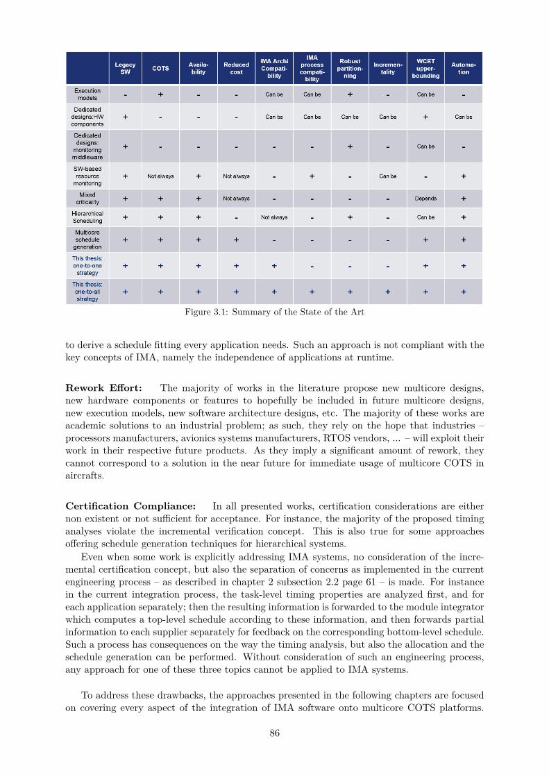
Figure 3.1: Summary of the State of the Art
to derive a schedule fitting every application needs. Such an approach is not compliant with thekey concepts of IMA, namely the independence of applications at runtime.
Rework Effort: The majority of works in the literature propose new multicore designs,new hardware components or features to hopefully be included in future multicore designs,new execution models, new software architecture designs, etc. The majority of these works areacademic solutions to an industrial problem; as such, they rely on the hope that industries –processors manufacturers, avionics systems manufacturers, RTOS vendors, ... – will exploit theirwork in their respective future products. As they imply a significant amount of rework, theycannot correspond to a solution in the near future for immediate usage of multicore COTS inaircrafts.
Certification Compliance: In all presented works, certification considerations are eithernon existent or not sufficient for acceptance. For instance, the majority of the proposed timinganalyses violate the incremental verification concept. This is also true for some approachesoffering schedule generation techniques for hierarchical systems.
Even when some work is explicitly addressing IMA systems, no consideration of the incre-mental certification concept, but also the separation of concerns as implemented in the currentengineering process – as described in chapter 2 subsection 2.2 page 61 – is made. For instancein the current integration process, the task-level timing properties are analyzed first, and foreach application separately; then the resulting information is forwarded to the module integratorwhich computes a top-level schedule according to these information, and then forwards partialinformation to each supplier separately for feedback on the corresponding bottom-level schedule.Such a process has consequences on the way the timing analysis, but also the allocation and theschedule generation can be performed. Without consideration of such an engineering process,any approach for one of these three topics cannot be applied to IMA systems.
To address these drawbacks, the approaches presented in the following chapters are focusedon covering every aspect of the integration of IMA software onto multicore COTS platforms.
86
The IMA architecture is central to all contributions proposed in this thesis. The rework ef-fort is minimized by considering COTS only, not relying on any modification of the softwarearchitecture, the hardware platform or eventually the firmware layer either. Multicore interfer-ence are modeled using static models so that tasks WCETs can be safely upper-bounded. Aschedulability analysis and a scheduling analysis rely on such interference models in order tocompute such bounds and determine in advance if a given allocation or schedule respects alltiming requirements of the system. The resulting analyses are compliant with the correspondingDO-178C verification objectives expressed for DAL A applications. Certification compliance isfurther ensured thanks to an adequate allocation and scheduling methodology proposed as theone-to-all integration strategy. Finally, the complete integration industrial process is covered,and in the case of the one-to-all integration strategy, enforces the current integration processfollowed by application suppliers and module integrators in current avionics systems.
87

88
Chapter 4
Integration Strategies Overview andSystem Model
This chapter presents all models used throughout this thesis. The software integration phaseof a system design includes two major activities: (i) the allocation of the software partitionson the hardware platform; (ii) the generation of a static MAF schedule deciding in advancethe reservation of time slots for partitions at runtime at each MAF cycle. Depending on whichintegration strategy and/or which activity is considered, some elements of the system model arerepresented differently. However, it is important to keep in mind that the goal of this chapteris to provide a complete presentation of all models and parameters used throughout this thesisdepending on the considered strategy or process. Extended details on how each element iscomputed will then be given in chapters 5 and 6.
This chapter is organized as follows. First, the assumptions are introduced, before a generaloverview of the two integration strategies proposed in this thesis is given. The current chapterthen proceeds with the description of the models of the software and hardware architecturesconsidered in this thesis.
In the rest of this thesis, the software/hardware allocation activity will be often referred toas allocation, and the partition- and/or task-level schedule generation as scheduling. In addi-tion, the methodologies proposed for the integration will be referred to as ”strategies”, and theallocation and schedule generation as ”processes” or ”activities” in the rest of this thesis.
4.1 Assumptions
In this section, we introduce all assumptions made in our work.
Core Allocation: we consider the case of static, fully partitioned scheduling on multicore,where IMA partitions and/or tasks are statically assigned to the cores of the same multicoreprocessor. Extended details on how the allocation is done will be given in chapter 6.
Core Synchronization: we assume all cores of the same multicore platform to be synchro-nized at runtime, and have core clock frequencies that are even multiples of each other respec-tively.
This assumption is essential for the validity of the computed schedules, which rely on theknowledge of the other cores schedules (cf chapter 5 for detailed explanations). In fact, theWCETs and schedules generated using the approaches described in this thesis rely on thisassumption, as they are computed while setting and/or assuming knowledge of runtime activityon other cores. If cores are not synchronized, it is more complicated to build a schedule and one
89
must consider highly pessimistic scenarios in order to compute a safe WCET upper-bound foreach task.
AMP Real-Time Operating System (RTOS) We assume the work presented in this the-sis to exploit AMP RTOS, even for an SMP usage of multicore processors.
Such an assumption has been made due to the fact that, at the time this thesis work has beenstarted, only AMP versions of ARINC 653 compliant RTOS where available. However, this doesnot limit the usage of this thesis to AMP RTOS only; it only means additional considerationsfor configuration have been taken into account in this thesis, which will be useless when usingan SMP RTOS for instance. As such, this thesis is able to adapt to both AMP and SMP RTOSthat will be made available in the electronic market in the future.
Scheduling policy: IMA partitions are scheduled statically, and are not preemptive. Insideeach partition, tasks can either be all preemptive or all non-preemptive, according to the choiceof system designers and function suppliers. Tasks are scheduled according to a fixed prioritypolicy, using priority levels assigned to them at design time. The partitions are scheduled accord-ing to a schedule plan elaborated by the module integrator, without any priority or allocationconsideration.
This assumption is based on current IMA architectures definition.
Monolithic Tasks Executions All tasks must complete their respective execution withinthe time window where the corresponding execution instance started running.
Such an assumption may be relaxed in current systems; however, such an assumption ismade in this thesis in order to simplify the problem, and be able to focus on multicore-relatedchallenges.
Timing Analysis during Schedule Generation: This thesis proposes an approach to au-tomaticaly generate static, partition-level schedules for IMA systems based on multicores. How-ever, as mentioned previously, tasks inside a partition can either be all preemptive or all nonpreemptive. It is important to note that the CP proposed for schedule generation then appliesonly for non-preemptive tasks. If one or several partitions implement preemptive tasks, thegeneration of schedule is replaced with the verification of existence of a valid schedule, as willbe explained in details in chapter 5 section 5.1.2 page 126.
Harmonic Periods: we assume the periods of all partitions to be implemented on the samemulticore module to be harmonic.
In fact in IMA systems, all partitions periods are harmonic on each separated module.
Timing Composability: tasks WCRTs and WCETs are computed as if the hardware archi-tecture was anomaly-free.
Current COTS multicores are usually not anomaly-free. To cope with anomalies and allowour WCET model to be valid despite the anomaly-free assumption, we propose to enforce thecomputed WCET for each task at runtime by not allowing any task to hold the CPU for the exactamount of time represented by the computed WCET bound. The produced WCETs being safeupper-bounds except for the advent of an anomaly occurring at runtime, the situation where atask tries to overrun its WCET at runtime could be considered as the occurrence of an anomaly.As such, although timing anomalies are not faulty events, we assume them to be treated as
90
such at runtime: the computed WCETs are assumed to be enforced through health monitoringmechanisms, and any task trying to overrun its WCET raises a faulty event. To do so, a specificrecovery action to be undertaken must be defined in the context of health monitoring.
Module and Hardware Platform Definition: we assume the hardware platform to consistin only one module, embedding one multicore processor.
This assumption does not limit the use of our work, since it is complementary to workstackling the problem of inter-module communications in IMA systems on multicore platforms,such as in [23] for instance. Such works usually make the assumption that a schedule has alreadybeen safely derived, which corresponds to the work done in this thesis for instance. As such,our work can be exploited in addition to the works in [23] in order to add consideration ofinter-application communications in multicore-based, distributed IMA systems.
Inter-Application Communications. As mentioned earlier, inter-application communica-tions are not addressed in this thesis. According to the ARINC 653 standard [1], these commu-nications must be handled using ARINC 653 ports following one of the two protocols – queuingor sampling – described in the standard. This implies additional memory considerations for theports memory context storing, and additional traversal time latencies and freshness considera-tions regarding the transfer of the corresponding message from the producer to the consumer.
Such additional considerations represent significant work to be done regarding messagescheduling, processor and interconnects speeds, etc. They are therefore usually tackled as atopic of their own. The complexity of such a problem explains why it has been identified as outof the scope of this thesis for simplification purposes: indeed, our work can be seen as the firststep towards legacy IMA transfer to multicore COTS, our main focus being on the difficulty ofcomputing safe WCET bounds in multicore environments.
On the other hand, state of the art works on inter-application communications usually assumethat tasks and/or partitions allocation, schedulability and WCET analysis, schedule generation,etc. – i.e. all activities covers in this thesis – have already been performed beforehand. In ourthesis, we make the assumption that inter-application communications will be handled once theactivities tackled by our work have been addressed. As such, our work is complementary to –and therefore can be used in addition to – state of the art work related to inter-applicationscommunications.
Shared Data and Message-Based Communications: intra-applications message-basedcommunications are implemented using shared memory. All communications are implementedusing dedicated shared memory spaces, the size of which is specified by the correspondingapplication supplier and is assumed to be large enough for one message. Each shared memoryspace is strictly limited to the storage of the content of the corresponding message.
Tasks involved in communications may have different period values and/or belong to twodifferent partitions.
We consider the sending of a message by a task to another task to be completed with certaintyat the end of execution of the sender task only. As such, the receiver task considers the messageto be available only at the end of execution of the sender task.
Finally, partition-level communications are deduced from task-level communications. Assuch, if two tasks from different partitions exchange messages or share data, the two corre-sponding partitions are said to be involved in some inter-partition communications.
In the rest of this thesis, we use the term communications to refer to both message basedcommunications or data sharing between tasks allocated to different cores.
91
It is important to note that communications are assumed to be the only valid justificationto implement shared memory in the system. Management of message queuing or sampling isdone as currently described by the ARINC653 standard [1].
Precedences Intra-application precedence relations can be defined, either between tasks orbetween partitions of the same application.
The IMA standard forbids inter-application precedences. As such, this assumption corre-sponds to an accurate feature of current IMA systems. However, if two partitions are involvedin some data exchange, we assume the system designer may want to enforce an ordering of thepartition windows occurence in the MAF schedule, as a preferred design choice rather than aprecedence requirement. Although it is not an actual precedence relation specified by system de-signers, such design preferences fit the representation of precedence relation. As a consequence,they are represented as such in this thesis for the sake of simplicity.
Core-Level Main Memory Privatization In this thesis, ideal multicore based designs arethe ones where the main memory is privatized at core level. By definition, each core is assignedmemory address ranges corresponding to the address spaces containing the memory contexts ofthe partitions that have been allocated to these cores respectively. Although the IMA definitionrequires out of partitions to have disjunct memory address spaces, in order to share some memoryareas. Two situations are then possible when two partitions are communicating: either they areboth allocated to the same core, or they are not. If all communications fall into the firstsituation, then the main memory is indeed privatized at core level. If not, then at least twocores share access to some memory space, in which case the main memory is not privatizedat core level. Strict main memory partitioning at core level can therefore truly be achievedonly if no inter-partition communication is implemented within the considered module, or ifall couples of partitions involved in inter-partition communications are allocated to the samecore. As a consequence, if there exists inter-partition communications, one would then only haveto carefully allocate shared memory areas to the main memory in order to achieve core-levelmemory privatization whenever possible with regards to the communications, partition contextsizes and memory layout.
It is important to note that this reasoning is applicable to COTS multicores. As a conse-quence, the main memory is to be privatized at core level whenever possible with regards to theinter-partition communications and hardware core-to-memory path wiring.
Multicore Interference Multicore interference considered in this thesis are related to theusage of the main memory by all the cores of a multicore processor. The corresponding sharedresources taken into account are the main memory space itself, but also the usage of mainmemory controllers and the interconnect linking cores to the memory controllers. As such, weabstract all devices of a multicore platform other than the cores, the main memory and theinterconnect, and focus on the interactions of the cores of a multicore processor with the mainmemory.
Multicore Architectures Targeted in this Thesis We consider a hardware platform withonly one bus-based multicore processor. The study proposed in this thesis handles activitiesand verification concerning the configuration of one multicore only. Therefore, every multicorepresent on the hardware platform of the system to be designed must be considered separately.As such, in the rest of this thesis, whenever we talk about partitions of a module, we actuallytalk about the partitions allocated to the multicore of the module on which the software platformhas been allocated to.
Finally, we only consider one cache level in the hardware platform, corresponding to eachcore’s L1 cache. As such, there is no shared cache considered in our contributions.
92
Scope of the CP formulation The efficiency and optimality of the algorithms used to solvethe implemented CPs are not the concern of this thesis, and are therefore out of scope. Inaddition, any mention of optimization achieved in this work is expressed with regards to SWaPreduction and/or minimization of the objective function, which is therefore independent fromeventual techniques and algorithms to optimize the CP search process.
4.2 Proposed Integration Strategies
4.2.1 Brief Overview
The main challenge when integrating IMA applications onto a hardware platform is the deriva-tion of time slices for each application according to their respective CPU time needs. In orderto derive accurate CPU time needs for each partition, one must first assess CPU time needs ofthe tasks of each partition respectively.
We propose two strategies for the integration of IMA applications onto multicore platforms,each strategy having its own advantages and drawbacks (see table 4.1):
• The One-to-All Integration Strategy (cf. figure 4.1): in this strategy, each supplieris responsible for statically allocating tasks of each partition to the cores of the multicoreplatform. Tasks of the same partition but on different cores are expected to be scheduledin parallel, so that in the final partition-level schedule, only one partition is scheduledon the entire multicore at any given time (cf figure 4.1). The outcome of the one-to-allintegration strategy is a static SMP-like scheduling table, similar to the one illustrated infigure 4.1.In this strategy of integration, the steps addressing activities performed by each applicationsupplier is assumed done by each of them independently of other application suppliers, onits own partitions and without knowledge of any partition of any other supplier that willbe integrated onto the same module. This corresponds to the way the software integrationis currently carried out in IMA systems.This strategy is in line with the robust partitioning and incremental certification accep-tance requirements of avionics systems. It therefore currently represents a potential be-ginning of solution for legacy IMA software porting to multicore modules.
• The One-to-One Integration Strategy (cf. figure 4.2): in this strategy, the soft-ware/hardware allocation is performed at partition-level. All tasks belonging to the samepartition are allocated to the core to which the corresponding partition has been allo-cated to. Then, during the schedule generation, the partition level is ignored as tasks arescheduled independently of the partition they belong to (cf. figure 4.2). The outcome ofthe one-to-one integration strategy is a static AMP scheduling table, similar to the oneillustrated in figure 4.2.In this strategy, every step is performed by a single person, for instance either a systemdesigner or a module integrator. However, it cannot be used for critical applications requir-ing strict robust time partitioning, as it does not prohibit inter-application interference atruntime, unless all partitions actually belong to the same critical application. This versionis still proposed as a potential solution for future systems, for instance for integrating ontoa multicore platform:
– One multi-partition application alone on an entire multicore platform,– Applications for which strict time partitioning may not be required and for which
system designer would accept the risk of having to reverify all applications if somemodification is applied to the corresponding module,
– Critical, non-IMA avionics software, i.e. in a multicore-based federated architecture.
93
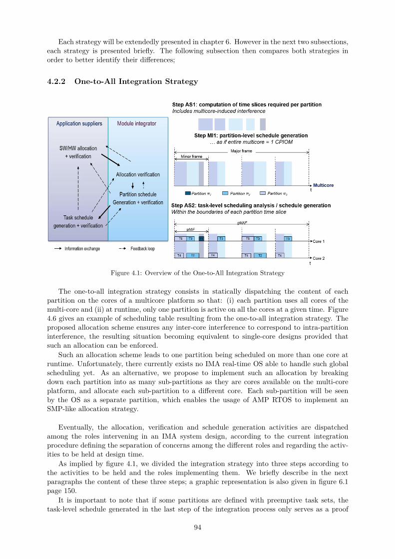
Each strategy will be extendedly presented in chapter 6. However in the next two subsections,each strategy is presented briefly. The following subsection then compares both strategies inorder to better identify their differences;
4.2.2 One-to-All Integration Strategy
Figure 4.1: Overview of the One-to-All Integration Strategy
The one-to-all integration strategy consists in statically dispatching the content of eachpartition on the cores of a multicore platform so that: (i) each partition uses all cores of themulti-core and (ii) at runtime, only one partition is active on all the cores at a given time. Figure4.6 gives an example of scheduling table resulting from the one-to-all integration strategy. Theproposed allocation scheme ensures any inter-core interference to correspond to intra-partitioninterference, the resulting situation becoming equivalent to single-core designs provided thatsuch an allocation can be enforced.
Such an allocation scheme leads to one partition being scheduled on more than one core atruntime. Unfortunately, there currently exists no IMA real-time OS able to handle such globalscheduling yet. As an alternative, we propose to implement such an allocation by breakingdown each partition into as many sub-partitions as they are cores available on the multi-coreplatform, and allocate each sub-partition to a different core. Each sub-partition will be seenby the OS as a separate partition, which enables the usage of AMP RTOS to implement anSMP-like allocation strategy.
Eventually, the allocation, verification and schedule generation activities are dispatchedamong the roles intervening in an IMA system design, according to the current integrationprocedure defining the separation of concerns among the different roles and regarding the activ-ities to be held at design time.
As implied by figure 4.1, we divided the integration strategy into three steps according tothe activities to be held and the roles implementing them. We briefly describe in the nextparagraphs the content of these three steps; a graphic representation is also given in figure 6.1page 150.
It is important to note that if some partitions are defined with preemptive task sets, thetask-level schedule generated in the last step of the integration process only serves as a proof
94
of existence of a valid task-level schedule, and will not correspond to the runtime task-levelschedule. On the contrary, if some partitions are defined with non-preemptive task sets, thenthe generated task-level schedule may be kept by the corresponding application supplier as thetask-level schedule to be enforced at runtime by the system. In the rest of this section, wedescribe in detail the three steps of the proposed strategy illustrated in figure 6.1.
SW/HW allocation The first step of the one-to-all integration strategy is about allocatingIMA partitions to the cores of a multicore platform, and deriving the needs of each partitionin terms of CPU time so that accurate time windows can be reserved to each partition in theschedule to be configured. The input of this step are the models of the software and the hardwareplatforms respectively, and the output is a task-to-core allocation along with an upper-boundon the CPU time budget that must be allocated to each partition at runtime.
As mentioned earlier, the software/hardware allocation is done by allocating tasks to coresfor each partition, with the condition that each partition uses all cores. These steps are per-formed by each application supplier, on her own partitions and independently from all otherpartitions. This implies to implement sub-partitions as separate partitions at configuration timeif legacy software is reused, for an AMP OS to be able to reproduce the selected task-to-coreallocation. As the tasks of a same partition usually communicate through shared data in thepartition memory context, inter-task has to be taken into account when searching for a task-to-core allocation. Two situations can occur: either (i) each partition can easily be divided intosub-partitions according to the defined communications, in which case simple module configura-tion at OS-level will suffice; or (ii) there exists no allocation combination where there is enoughmemory to define additional necessary shared areas for all communications involving two tasksallocated to different cores.
Aside from selecting a task-to-core allocation for each partition, each supplier is responsiblewith the verification of the enforcement of all associated timing requirements in the selectedallocation. This includes estimating tasks WCETs in order to check whether the associateddeadline can be enforced even in the worst-case situation. Combined with the allocation setting,WCETs are necessary to derive each partition CPU time budget as well. Finally, once a supplierhas selected an allocation, she can derive the CPU time budget needed by each partition for thecorresponding tasks execution. IMA partitions are often defined as periodic, and all partitionsperiods are assumed to be multiple of each other. This enables the runtime schedule to be bro-ken down into frames, one frame corresponding to the minor time frame (MIF) and a completepattern of the schedule corresponding to the major time frame (MAF) (see figure 44). As aconsequence, for a given partition, an application supplier must provide one CPU time budgetper frame for a complete MAF.
The first step of the integration strategy illustrated in figure 4.1 would have to be performedby each supplier separately. The inputs of this step are the software and the hardware models.The variables are the tasks to cores and memory allocation, but also the tasks WCETs and thepartitions CPU time windows. The output of this step is a task-to-core allocation, proven to becorrect. The correctness is ensured by embedding the interference-aware response time analysisproposed in this thesis for static WCET upper-bounding. Doing so expresses the requirementthat all tasks are allocated exactly on one core, all cores are used by each partition, and every taskwould always be able to respect its timing requirements, including deadline, communications,precedence relations, etc. Eventually, tasks WCETs and core allocation are used in order toderive the corresponding partitions CPU time budget needs per cycle.
Global allocation verification and partition-level schedule generation The secondstep of the one-to-all integration process consists in verifying that the overall allocation and thecorresponding time budgets per core is feasible in practice, and also the generation of a partition-
95
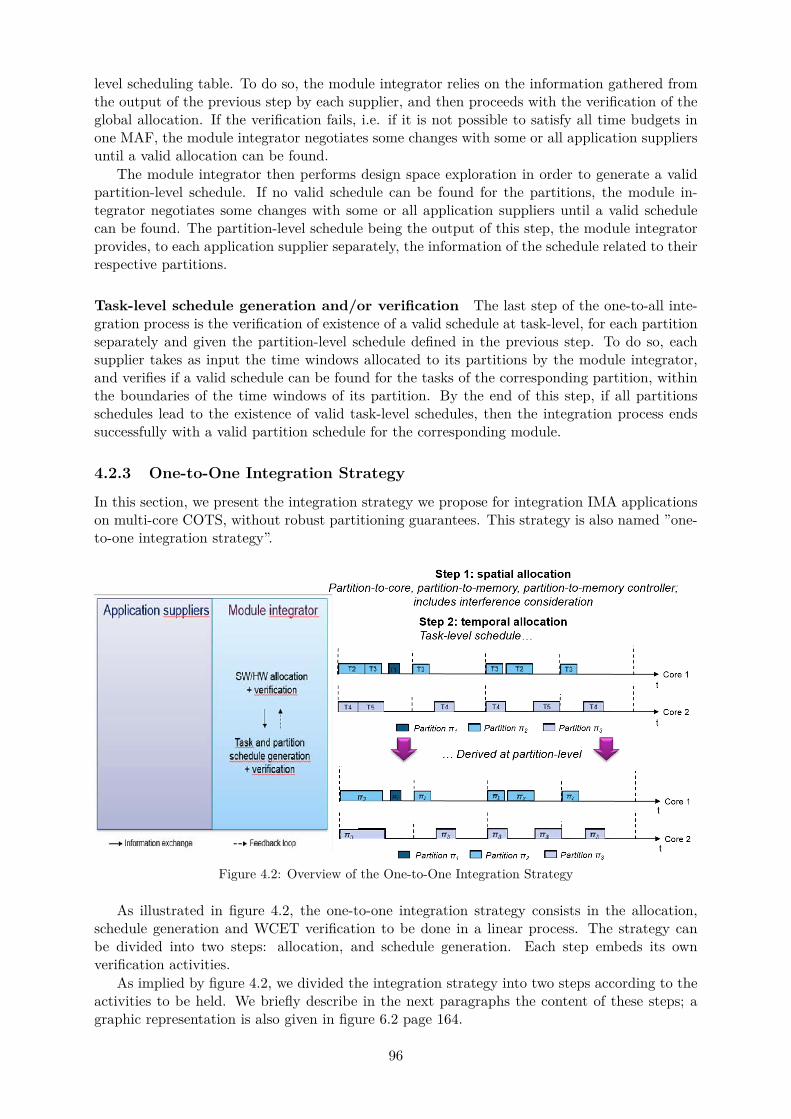
level scheduling table. To do so, the module integrator relies on the information gathered fromthe output of the previous step by each supplier, and then proceeds with the verification of theglobal allocation. If the verification fails, i.e. if it is not possible to satisfy all time budgets inone MAF, the module integrator negotiates some changes with some or all application suppliersuntil a valid allocation can be found.
The module integrator then performs design space exploration in order to generate a validpartition-level schedule. If no valid schedule can be found for the partitions, the module in-tegrator negotiates some changes with some or all application suppliers until a valid schedulecan be found. The partition-level schedule being the output of this step, the module integratorprovides, to each application supplier separately, the information of the schedule related to theirrespective partitions.
Task-level schedule generation and/or verification The last step of the one-to-all inte-gration process is the verification of existence of a valid schedule at task-level, for each partitionseparately and given the partition-level schedule defined in the previous step. To do so, eachsupplier takes as input the time windows allocated to its partitions by the module integrator,and verifies if a valid schedule can be found for the tasks of the corresponding partition, withinthe boundaries of the time windows of its partition. By the end of this step, if all partitionsschedules lead to the existence of valid task-level schedules, then the integration process endssuccessfully with a valid partition schedule for the corresponding module.
4.2.3 One-to-One Integration Strategy
In this section, we present the integration strategy we propose for integration IMA applicationson multi-core COTS, without robust partitioning guarantees. This strategy is also named ”one-to-one integration strategy”.
Figure 4.2: Overview of the One-to-One Integration Strategy
As illustrated in figure 4.2, the one-to-one integration strategy consists in the allocation,schedule generation and WCET verification to be done in a linear process. The strategy canbe divided into two steps: allocation, and schedule generation. Each step embeds its ownverification activities.
As implied by figure 4.2, we divided the integration strategy into two steps according to theactivities to be held. We briefly describe in the next paragraphs the content of these steps; agraphic representation is also given in figure 6.2 page 164.
96
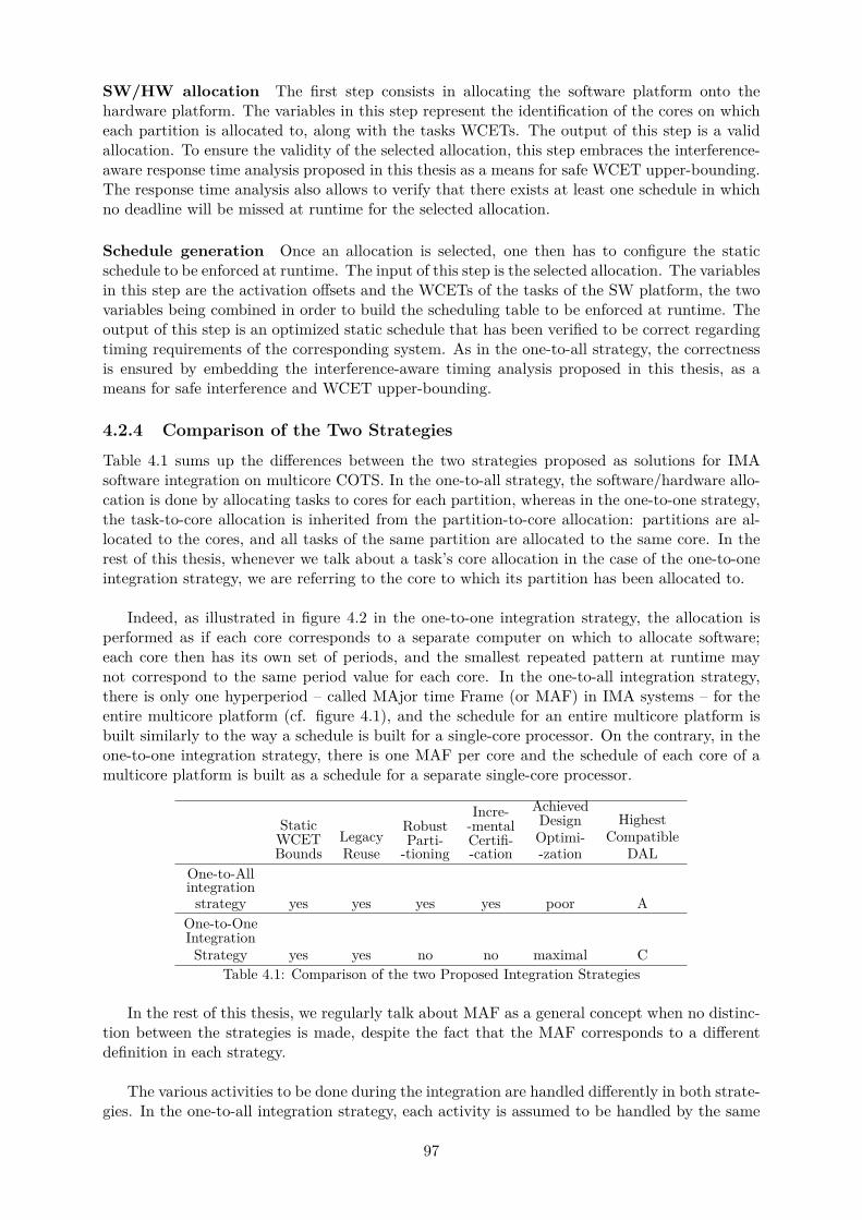
SW/HW allocation The first step consists in allocating the software platform onto thehardware platform. The variables in this step represent the identification of the cores on whicheach partition is allocated to, along with the tasks WCETs. The output of this step is a validallocation. To ensure the validity of the selected allocation, this step embraces the interference-aware response time analysis proposed in this thesis as a means for safe WCET upper-bounding.The response time analysis also allows to verify that there exists at least one schedule in whichno deadline will be missed at runtime for the selected allocation.
Schedule generation Once an allocation is selected, one then has to configure the staticschedule to be enforced at runtime. The input of this step is the selected allocation. The variablesin this step are the activation offsets and the WCETs of the tasks of the SW platform, the twovariables being combined in order to build the scheduling table to be enforced at runtime. Theoutput of this step is an optimized static schedule that has been verified to be correct regardingtiming requirements of the corresponding system. As in the one-to-all strategy, the correctnessis ensured by embedding the interference-aware timing analysis proposed in this thesis, as ameans for safe interference and WCET upper-bounding.
4.2.4 Comparison of the Two Strategies
Table 4.1 sums up the differences between the two strategies proposed as solutions for IMAsoftware integration on multicore COTS. In the one-to-all strategy, the software/hardware allo-cation is done by allocating tasks to cores for each partition, whereas in the one-to-one strategy,the task-to-core allocation is inherited from the partition-to-core allocation: partitions are al-located to the cores, and all tasks of the same partition are allocated to the same core. In therest of this thesis, whenever we talk about a task’s core allocation in the case of the one-to-oneintegration strategy, we are referring to the core to which its partition has been allocated to.
Indeed, as illustrated in figure 4.2 in the one-to-one integration strategy, the allocation isperformed as if each core corresponds to a separate computer on which to allocate software;each core then has its own set of periods, and the smallest repeated pattern at runtime maynot correspond to the same period value for each core. In the one-to-all integration strategy,there is only one hyperperiod – called MAjor time Frame (or MAF) in IMA systems – for theentire multicore platform (cf. figure 4.1), and the schedule for an entire multicore platform isbuilt similarly to the way a schedule is built for a single-core processor. On the contrary, in theone-to-one integration strategy, there is one MAF per core and the schedule of each core of amulticore platform is built as a schedule for a separate single-core processor.
StaticWCETBounds
LegacyReuse
RobustParti-
-tioning
Incre--mentalCertifi--cation
AchievedDesignOptimi--zation
HighestCompatible
DALOne-to-Allintegration
strategy yes yes yes yes poor AOne-to-OneIntegration
Strategy yes yes no no maximal CTable 4.1: Comparison of the two Proposed Integration Strategies
In the rest of this thesis, we regularly talk about MAF as a general concept when no distinc-tion between the strategies is made, despite the fact that the MAF corresponds to a differentdefinition in each strategy.
The various activities to be done during the integration are handled differently in both strate-gies. In the one-to-all integration strategy, each activity is assumed to be handled by the same
97
role as in the current IMA integration process (module integrator, application supplier, systemdesigner...) whereas the one-to-one integration strategy considers all activities are handled bythe same person; this would imply one of the current profiles to handle activities that are usuallyout of their scope (for instance, having a module integrator performing a task-level timing anal-ysis). Such a separation of concerns implemented in the one-to-all integration strategy forcessome elements of the software model – along with the allocation and the scheduling activities – tobe defined accordingly. For instance regarding the schedulability verification: in the one-to-onestrategy, the role performing the verification can do so with the knowledge of the entire softwareplatform, and therefore, rely on the knowledge of the value of the MAF. It is not the case inthe one-to-all strategy, where the module integrator must produce a partition table and verifyit, before each supplier can work on their own time windows allocated to the partitions theydesigned respectively and verify that their partitions needs are all respected. This implies theschedulability verification to be split into several steps, as will be explained in details in chapter 6.
As mentioned in the assumptions, we assume an AMP RTOS to be exploited when applyingthe contributions of this thesis. However, AMP RTOS forbid the allocation of a partition to morethan one core, contrary to what is done in the one-to-all integration strategy. As a consequence,a workaround to be able to still implement the strategy using an AMP RTOS has been found.
In practice, in order to implement the one-to-all integration strategy using legacy IMAsoftware with an AMP RTOS, partitions that can be scheduled simultaneously on differentcores at runtime are partitions belonging to the same application only. As such when reusinglegacy software, if an application is defined only as one partition, this means that only onecore will be active on the entire multicore when that application is scheduled at runtime. Analternative to benefit as much as possible from software parallelization capabilities of multicorearchitectures is to modify single-partition applications in order to turn them into multi-partitionapplications. In the latter case, the corresponding suppliers would therefore have to redefinetheir application so that it consists in several tasks that can be executed in parallel at runtime.
This thesis contributions assist suppliers in such situations. For each partition to be splitinto several partitions, the proposed allocation problem formulation searches for the optimalallocation for the tasks to the cores while considering them to be scheduled simultaneously atruntime. The resulting task-to-core allocation then defines the new multi-partition definition ofthe application. Extended details about how partitions are split into several partitions such thattheir respective tasks can be scheduled on different cores in parallel as expected in the one-to-allstrategy will be given in chapter 6.
The separation of concerns in the one-to-all integration strategy serves the enforcementof legacy certification requirements that are central to the IMA concept. More precisely, theseparation of concerns allows the one-to-all integration strategy to enforce robust partitioningand be eligible to incremental certification acceptance. Indeed, WCETs are upper-bounded foreach application independently from each other; one modification on one application has noimpact on any other application which therefore do not have to be re-verified. These propertiesare specific to the one-to-all integration strategy, as they are not verified in the one-to-oneintegration strategy.
However, the one-to-all integration strategy may lead to designs that are less optimized thanin the one-to-one integration strategy, where every activity is handled altogether and guide theselection of the final configuration. In addition, this strategy is easier to implement than theone-to-all integration strategy in the sense that it is more straightforward. It also may lead tomore optimized system designs in terms of SWaP reduction achievement.
Finally, the fact that the one-to-all integration strategy manages to get rid on inter-applicationinterference while following an incremental design and verification process makes it eligible foruse with up to DAL A applications. The one-to-one integration strategy can be exploited for
98

DAL A applications only in the case of one multi-partition DAL A application being allocatedalone on the entire multicore module. In all other cases, the one-to-one strategy can be used forup to DAL C applications only, or non-IMA software.
4.3 Software Architecture Model
Several models are defined in order to represent the same element of a system, depending onthe activity to be performed. For instance, tasks are not represented the same way whetherthe allocation or the schedule generation problems are considered; they are not representedexactly the same way for both strategies either. This chapter presents all modeling elementsexploited to represent the software platform at some point of this thesis; extensive details onwhich elements are used in which strategy/activity will be given in chapters dedicated to eachintegration strategy.
Let AS represent the set of application suppliers involved in the development of avionicsfunctions considered for integration on the same module, and asi P AS denote the identifier ofthe ith application supplier. Let then Nasi
P (resp. NasiT ) denote the total number of partitions
(resp. tasks of all partitions) the ith supplier designed or is in charge of designing, and NP (resp.NT ) the total number of partitions (resp. tasks) in the software platform considered.
Finally, for simplicity of the models representation, we assume one application to be assignedper supplier, and partitions πi and tasks τj of the software platform to have unique identifiers.
Core Allocation
The elements of the model representing the software allocation to the cores depend on whichintegration strategy is addressed. Let NC denote the total number of cores available on theconsidered multicore.
One-to-All Integration Strategy As illustrated in figure 4.6, in the one-to-all integrationstrategy, the core allocation is done at task level. We represent such a task-to-core allocationusing a boolean matrix na defined as follows:
naij “
"
1 if τj is allocated to core i,0 otherwise. (4.1)
The size of na depends on the supplier exploiting our approach; it is NC ˆ NasiT for the ith
supplier.Some affinities between tasks and cores might be defined, as well as exclusion constraints.
We model such requirements by defining two boolean matrices taskCoreAff and taskCoreExclrespectively as follows:
taskCoreAffij “
"
1 if τj must be allocated to core i,0 if no such requirement has been expressed. (4.2)
taskCoreExclij “"
1 if τj must not be allocated to core i,0 if no such requirement has been expressed. (4.3)
As for na, the size of taskCoreAff and taskCoreExcl is NC ˆNasiT for the ith supplier.
One-to-One Integration Strategy As illustrated in figure 4.5, in the one-to-one-integrationstrategy, the core allocation is done at partition level. We represent the partition-to-core allo-cation using a boolean matrix a defined as follows:
aij “
"
1 if πj is allocated to core i,0 otherwise. (4.4)
The size of a is NC ˆ NP , where NP is the total number of partitions designed by the corre-sponding application supplier.
99
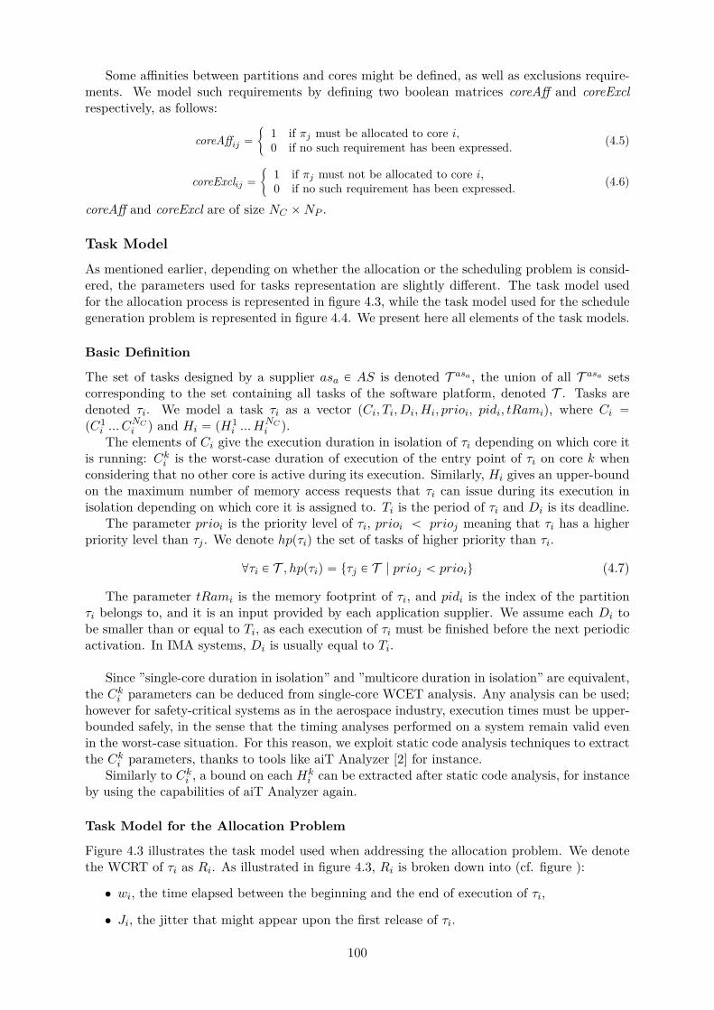
Some affinities between partitions and cores might be defined, as well as exclusions require-ments. We model such requirements by defining two boolean matrices coreAff and coreExclrespectively, as follows:
coreAffij “
"
1 if πj must be allocated to core i,0 if no such requirement has been expressed. (4.5)
coreExclij “"
1 if πj must not be allocated to core i,0 if no such requirement has been expressed. (4.6)
coreAff and coreExcl are of size NC ˆNP .
Task Model
As mentioned earlier, depending on whether the allocation or the scheduling problem is consid-ered, the parameters used for tasks representation are slightly different. The task model usedfor the allocation process is represented in figure 4.3, while the task model used for the schedulegeneration problem is represented in figure 4.4. We present here all elements of the task models.
Basic Definition
The set of tasks designed by a supplier asa P AS is denoted T asa , the union of all T asa setscorresponding to the set containing all tasks of the software platform, denoted T . Tasks aredenoted τi. We model a task τi as a vector pCi, Ti, Di, Hi, prioi, pidi, tRamiq, where Ci “pC1
i ... CNCi q and Hi “ pH
1i ... H
NCi q.
The elements of Ci give the execution duration in isolation of τi depending on which core itis running: Cki is the worst-case duration of execution of the entry point of τi on core k whenconsidering that no other core is active during its execution. Similarly, Hi gives an upper-boundon the maximum number of memory access requests that τi can issue during its execution inisolation depending on which core it is assigned to. Ti is the period of τi and Di is its deadline.
The parameter prioi is the priority level of τi, prioi ă prioj meaning that τi has a higherpriority level than τj . We denote hppτiq the set of tasks of higher priority than τi.
@τi P T , hppτiq “ tτj P T | prioj ă prioiu (4.7)
The parameter tRami is the memory footprint of τi, and pidi is the index of the partitionτi belongs to, and it is an input provided by each application supplier. We assume each Di tobe smaller than or equal to Ti, as each execution of τi must be finished before the next periodicactivation. In IMA systems, Di is usually equal to Ti.
Since ”single-core duration in isolation” and ”multicore duration in isolation” are equivalent,the Cki parameters can be deduced from single-core WCET analysis. Any analysis can be used;however for safety-critical systems as in the aerospace industry, execution times must be upper-bounded safely, in the sense that the timing analyses performed on a system remain valid evenin the worst-case situation. For this reason, we exploit static code analysis techniques to extractthe Cki parameters, thanks to tools like aiT Analyzer [2] for instance.
Similarly to Cki , a bound on each Hki can be extracted after static code analysis, for instance
by using the capabilities of aiT Analyzer again.
Task Model for the Allocation Problem
Figure 4.3 illustrates the task model used when addressing the allocation problem. We denotethe WCRT of τi as Ri. As illustrated in figure 4.3, Ri is broken down into (cf. figure ):
• wi, the time elapsed between the beginning and the end of execution of τi,
• Ji, the jitter that might appear upon the first release of τi.
100

Figure 4.3: Task Model for the Allocation Problem
By definition, as illustrated in figure 4.3, wi includes all waiting delays suffered by τi dueto preemption or resource sharing. Moreover, wi being computed using a maximum WCRTupper-bound, we assume wi can be considered to be a maximum upper-bound on the WCET ofτi. As such, wi will be referred as the WCET upper-bound of τi in the rest of this thesis.
Task Model for the Schedule Generation Problem
Figure 4.4: Task Model for the Scheduling Problem
Figure 4.4 illustrates the task model used when addressing the scheduling problem. Foreach task τi, we define an array ptO1
i ... tOnbActivii q of activation offsets of all instances of τi,
where nbActivi represents the total number of instances of τi in one MAF to be considered whenbuilding a schedule at task-level. The parameter nbActivi is computed differently dependingon the integration strategy considered, and must include the total number of instances of τi inone MAF so that all situations of inter-task interference potentially occurring at runtime arecovered when computing WCET bounds. Details on how nbActivi is computed in each strategywill be given later in this chapter.
Each activation date tOki corresponds to the kth activation of τi, and therefore respects thefollowing property, in both integration strategies:
@τi P T ,@k P r1;nbActivis , pk ´ 1q ˆ Ti ď tOki ď k ˆ Ti (4.8)
101
For preemptive tasks, tOki corresponds to the jitter upon first activation of the kth instanceof τi, scheduled only once in the MAF schedule; more details about such an equivalence will beprovided later in this chapter.
An analogous reasoning is used to build an array of WCETs pw1i .. w
nbActivii q, where wki
corresponds to an upper-bound of the WCET of the kth instance of τi, as will be explained indetails later as well.
Partition Model
As for the task model, the partition model varies depending on the integration strategy and theactivity considered. For understanding purposes while introducing each parameter involved inthe partitions models, the reader may want to refer to the examples of schedules computed as aresult of each of the one-to-all and one-to-one integration strategies respectively, illustrated infigures 4.6 (page 104) and 4.5 (page 104).
Basic Definition
The set of partitions designed by the ath supplier asa is denoted Pasa , the union of all Pasa setscorresponding to the set containing all partitions of the software platform, denoted P. Partitionsare denoted πi. We define Pi as the period of πi, i.e. the time interval between two successivetime windows of πi. The task-to-partition allocation is an input provided by each applicationsupplier and is represented by the following boolean matrix PART :
PARTji “
"
1 if τi belongs to partition πj ,0 otherwise (4.9)
The size of PART is NP ˆ NT in the one-to-one integration strategy, NasaP ˆ Nasa
T for eachsupplier asa in the one-to-all integration strategy.
The parameter pidi of each task τi giving the index of the partition it belongs to is definedas follows:
@πi P P, pidi “NPÿ
j“1j ˆ PARTji (4.10)
To ease explanations in the rest of this thesis, we use the notation τi P πj to express thefact that a task τi belongs to partition πj .
This thesis work may be used both for preemptive and non-preemptive task sets. As such, wedefine a boolean variable isPreemptivei configuring whether or not the task set inside partitionπi is preemptive, in order to be able to account for both cases in the contributions proposed inthis thesis; isPreemptivei is defined as follows:
@πi P P, isPreemptivei “
"
1 if tasks inside πi are preemptive,0 otherwise. (4.11)
Partition Cycle
It is important to note that all tasks are periodic, and all tasks of the same partition may nothave the same periods. As such, not only is the schedule of activations of partitions periodicover time – the MAF being the smallest pattern repeated infinitely – but inside each partitionis there a pattern of activation of its tasks that is repeated over time as well.
As mentioned earlier, such cycle is referred to as partition cycle throughout this thesis, andcan have a different length depending on the partition, as illustrated in figure 4.7. The lengthof a partition cycle depends on the periods of activation of its tasks and corresponds to thesmallest repeated pattern over time. All periods being harmonic, the duration of the smallestpattern of tasks activations inside one given partition πi corresponds to the maximum period ofits tasks max
pidj“ipTjq.
102
Partition Model for the Allocation Problem
We proceed define a CPU time budget Eki per partition πi for each frame k of their respectivepartition cycle, as illustrated in figures 4.5 and 4.6 for both strategies. Eki corresponds to amaximum bound on the worst-case CPU time budget that must be reserved for πi’s tasks in thekth frame of one MAF. Although the general definition of the Eki is valid in both strategies, thenumber of frames k to be considered depends on the strategy targeted.
In the one-to-one integration strategy, the number of frames to be considered in the allocationproblem is nFrames for all partitions, where nFrames is computed using equation (4.28) page108 as will be explained later in this chapter.
In the one-to-all integration strategy, the number of frames to be considered is nFramesifor each partition πi; each nFramesi is computed using equation (4.23) page 107 as will beexplained later in this chapter.
If the first CPU window of a given partition occurs earlier than the release of all its tasks,then no task is scheduled at the beginning of the window. This is not ideal in a schedule sincethis leads to slack times in each time window where the corresponding core is idle. Such asituation also jeopardizes the enforcement of task-level timing requirements.
In fact, partition windows are dimensioned so that the WCET of all its tasks supposed to berunning in that window fit in it, and the expressed budgets do not take into consideration slacktimes or tasks jitters upon first activation. Windows usually include a safety margin; however,if tasks jitters have not been taken into account when dimensioning the partitions windowsor when configuring the schedule, then if the slack time occurring at runtime is bigger thanthe safety margin introduced in the window, then a task may become unable to complete itsexecution before the end of the partition window or overrun its deadline.
As a consequence, it is very important to translate task-level jitters upon first activationinformation into partition-level jitters upon first time window information to make sure that,during the feasibility and schedulability analyses, the partition windows respect their tasks jit-ters and dependence constraints. To do so, we define a jitter for the first time window of eachpartition πi respectively, denoted pJi. This jitter corresponds to the first window only, and isexploited during the allocation search and the related feasibility analysis.
On the other hand, when configuring a schedule at partition-level, one must make sure thatpartition windows are relevant for the corresponding task level. To be able to perform such averification and define relevant partition windows, we define a jitter for each partition window,denoted as latestki for the kth window of πi. These jitters are exploited during the schedulegeneration phase and in the corresponding schedulability analysis. The latestki parameters enableto make the link between the task-level feasibility analysis and the partition-level feasibilityanalysis. This will be explained in greater details later in chapter 5.
Additional Parameters Specific to the One-to-All Integration Strategy In the one-to-all integration strategy, partitions memory footprints respectively are allocated to the mainmemory depending on their tasks core allocation. The memory context of tasks allocated toa given core will be stored in some main memory area addressable by that core. As will bepresented in section 4.4, the memory storage area has been divided into sub-areas linked to eachmemory controller. Such subdivision usually corresponds to non unified memory architectureswhere each memory controller allows access only to a portion of the main memory. It can also beused in other, unified architectures but provided that the hardware platform offers safe memorypartitioning capabilities, as has been identified in the last revision of the ARINC 653 standard[1] as IMA-friendly features for future multicore-based IMA systems. As such, our work is ap-plicable to any multicore which architecture can be assimilated to the schema given in figure 4.9page 112.
103

When integrating several partitions onto a multicore module, the module integrator needsto know the memory footprint per core of each partition in order to verify the realism of thememory allocation regarding the actually available memory capacity. To be able to performsuch a verification, we define for each partition πi a vector ppRam1
i ... pRamNMCi q where pRamk
i
denotes the size of the part of πi’s memory context supposed to be stored in some main memoryarea that is addressable by the kth memory controller. By construction, pRamk
i correspondsto the sum of the memory contexts of the tasks τj of πi that have been allocated to the kthmemory controller, tRamj . Each pRamk
i can be seen as a memory budget per core and iscomputed according to the following relation:
@k P r1;NMCs,@πi P P, pRamki “
NTÿ
j“1PARTij ˆ t2mckj ˆ tRamj (4.12)
where the boolean t2mckj is equal to one if τj uses the memory controller j and zero if it is notthe case, as will be explained later when defining matrix t2mc in equation (4.36) page 114.
Partition Model for the Schedule Generation Problem
Figure 4.5: Example of MAF Schedule Resulting from the One-to-One Integration Strategy
Figure 4.6: Example of MAF Schedule Resulting from the One-to-All Integration Strategy
To be able to compute a partition-level schedule, CPU time windows are reserved for eachpartition πi according to their respective periodicity. A window – or partition window, or
104
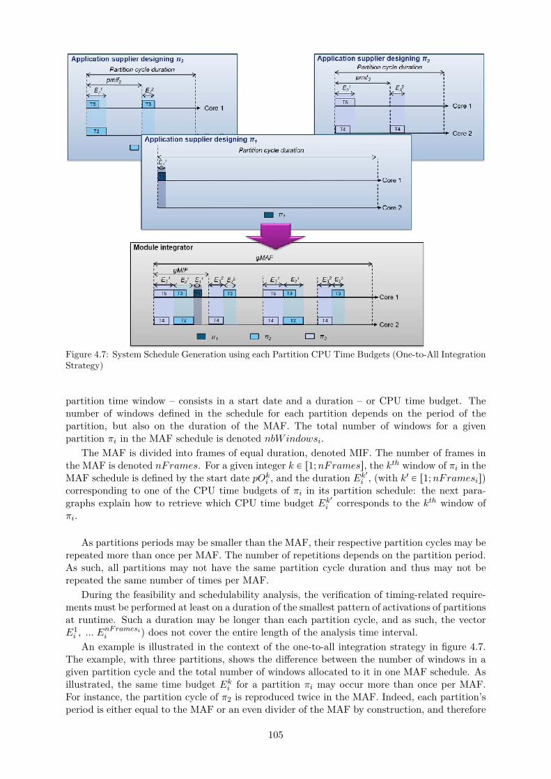
Figure 4.7: System Schedule Generation using each Partition CPU Time Budgets (One-to-All IntegrationStrategy)
partition time window – consists in a start date and a duration – or CPU time budget. Thenumber of windows defined in the schedule for each partition depends on the period of thepartition, but also on the duration of the MAF. The total number of windows for a givenpartition πi in the MAF schedule is denoted nbWindowsi.
The MAF is divided into frames of equal duration, denoted MIF. The number of frames inthe MAF is denoted nFrames. For a given integer k P r1;nFramess, the kth window of πi in theMAF schedule is defined by the start date pOki , and the duration Ek1i , (with k1 P r1;nFramesis)corresponding to one of the CPU time budgets of πi in its partition schedule: the next para-graphs explain how to retrieve which CPU time budget Ek1i corresponds to the kth window ofπi.
As partitions periods may be smaller than the MAF, their respective partition cycles may berepeated more than once per MAF. The number of repetitions depends on the partition period.As such, all partitions may not have the same partition cycle duration and thus may not berepeated the same number of times per MAF.
During the feasibility and schedulability analysis, the verification of timing-related require-ments must be performed at least on a duration of the smallest pattern of activations of partitionsat runtime. Such a duration may be longer than each partition cycle, and as such, the vectorE1i , ... E
nFramesii q does not cover the entire length of the analysis time interval.
An example is illustrated in the context of the one-to-all integration strategy in figure 4.7.The example, with three partitions, shows the difference between the number of windows in agiven partition cycle and the total number of windows allocated to it in one MAF schedule. Asillustrated, the same time budget Eki for a partition πi may occur more than once per MAF.For instance, the partition cycle of π2 is reproduced twice in the MAF. Indeed, each partition’speriod is either equal to the MAF or an even divider of the MAF by construction, and therefore
105
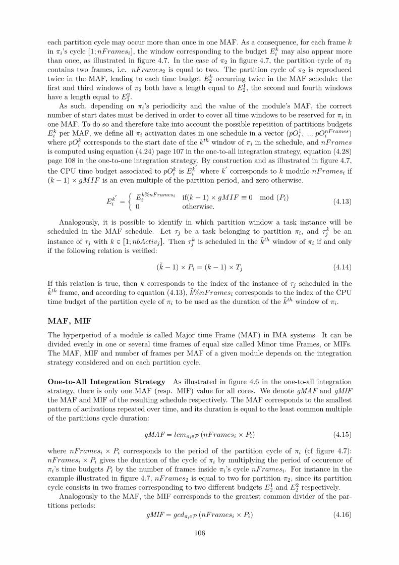
each partition cycle may occur more than once in one MAF. As a consequence, for each frame kin πi’s cycle r1;nFramesis, the window corresponding to the budget Eki may also appear morethan once, as illustrated in figure 4.7. In the case of π2 in figure 4.7, the partition cycle of π2contains two frames, i.e. nFrames2 is equal to two. The partition cycle of π2 is reproducedtwice in the MAF, leading to each time budget Ek2 occurring twice in the MAF schedule: thefirst and third windows of π2 both have a length equal to E1
2 , the second and fourth windowshave a length equal to E2
2 .As such, depending on πi’s periodicity and the value of the module’s MAF, the correct
number of start dates must be derived in order to cover all time windows to be reserved for πi inone MAF. To do so and therefore take into account the possible repetition of partitions budgetsEki per MAF, we define all πi activation dates in one schedule in a vector ppO1
i , ... pOnFramesi q
where pOki corresponds to the start date of the kth window of πi in the schedule, and nFramesis computed using equation (4.24) page 107 in the one-to-all integration strategy, equation (4.28)page 108 in the one-to-one integration strategy. By construction and as illustrated in figure 4.7,the CPU time budget associated to pOki is Ek
1
i where k1 corresponds to k modulo nFramesi ifpk ´ 1q ˆ gMIF is an even multiple of the partition period, and zero otherwise.
Ek1
i “
"
Ek%nFramesii ifpk ´ 1q ˆ gMIF ” 0 mod pPiq
0 otherwise. (4.13)
Analogously, it is possible to identify in which partition window a task instance will bescheduled in the MAF schedule. Let τj be a task belonging to partition πi, and τkj be aninstance of τj with k P r1;nbActivjs. Then τkj is scheduled in the kth window of πi if and onlyif the following relation is verified:
pk ´ 1q ˆ Pi “ pk ´ 1q ˆ Tj (4.14)
If this relation is true, then k corresponds to the index of the instance of τj scheduled in thekth frame, and according to equation (4.13), k%nFramesi corresponds to the index of the CPUtime budget of the partition cycle of πi to be used as the duration of the kth window of πi.
MAF, MIF
The hyperperiod of a module is called Major time Frame (MAF) in IMA systems. It can bedivided evenly in one or several time frames of equal size called Minor time Frames, or MIFs.The MAF, MIF and number of frames per MAF of a given module depends on the integrationstrategy considered and on each partition cycle.
One-to-All Integration Strategy As illustrated in figure 4.6 in the one-to-all integrationstrategy, there is only one MAF (resp. MIF) value for all cores. We denote gMAF and gMIFthe MAF and MIF of the resulting schedule respectively. The MAF corresponds to the smallestpattern of activations repeated over time, and its duration is equal to the least common multipleof the partitions cycle duration:
gMAF “ lcmπiPP pnFramesi ˆ Piq (4.15)
where nFramesi ˆ Pi corresponds to the period of the partition cycle of πi (cf figure 4.7):nFramesi ˆ Pi gives the duration of the cycle of πi by multiplying the period of occurence ofπi’s time budgets Pi by the number of frames inside πi’s cycle nFramesi. For instance in theexample illustrated in figure 4.7, nFrames2 is equal to two for partition π2, since its partitioncycle consists in two frames corresponding to two different budgets E1
2 and E22 respectively.
Analogously to the MAF, the MIF corresponds to the greatest common divider of the par-titions periods:
gMIF “ gcdπiPP pnFramesi ˆ Piq (4.16)
106

In the case of harmonic periods, the MAF and MIF respectively correspond to the maximumand minimum partition periods and can thus also be computed as follows:
gMAF “ maxπiPP
pnFramesi ˆ Piq (4.17)
gMIF “ minπiPP
pnFramesi ˆ Piq (4.18)
One-to-One Integration Strategy As illustrated in figure 4.5 in the one-to-one integrationstrategy, each core may have a different MAF and MIF. Let MAFp (resp. MIFp) denote theMAF (resp. the MIF) of core p. By definition, MAFp and MIFp can be computed as followsfor all core p:
@p P r1;NCs, MAFp “ lcmπiPP papi ˆ nFramesi ˆ Piq (4.19)
@p P r1;NCs, MIFp “ gcdπiPP papi ˆ nFramesi ˆ Piq (4.20)
Similarly to the one-to-all integration strategy, in case of harmonic periods, the MAF andMIF of each core can be computed as follows:
@p P r1;NCs, MAFp “ maxπiPP
papi ˆ nFramesi ˆ Piq (4.21)
@p P r1;NCs, MIFp “ minπiPP
papi ˆ nFramesi ˆ Piq (4.22)
Number of Frames and Task Instances
This subsection describes how the parameters nbActivi for each task τi, nFramesi for eachpartition πi and nbFrames are computed. We provide here brief explanations on how theseparameters have a different impact in each strategy before providing the equations exploited forcomputing the corresponding parameters respectively. Extended details about how each param-eter is used will be provided in chapter 6 when detailing each integration strategy proposed.
One-to-All Integration Strategy In the one-to-all integration strategy, the number offrames to be considered in one MAF depends on which activity (allocation or schedule gen-eration) is performed and by which role (supplier or integrator). An illustration is given infigure 4.7.
For intra-partition analysis purposes, one partition cycle is analyzed. The number of framesnbFramesi per partition πi identifies the number of windows Eki in a partition cycle.
For each partition πi, the parameter nFramesi is computed as follows:
@asa P AS,@πi P Pasa , nFramesi “maxpidj“i
pTjq
minpidj“i
pTjq(4.23)
Periods being harmonic, nFramesi is always an integer for all partitions πi.On the other hand, for partition level schedule generation, the total number of frames
nFrames into which the MAF schedule can be divided is exploited, in order for the mod-ule integrator to be able to derive how many times each budget Eki is going to appear in theoverall schedule. The total number of frames in one MAF schedule is computed as follows:
nFrames “gMAFgMIF (4.24)
Similarly to nFramesi, nFrames is always an integer.
107
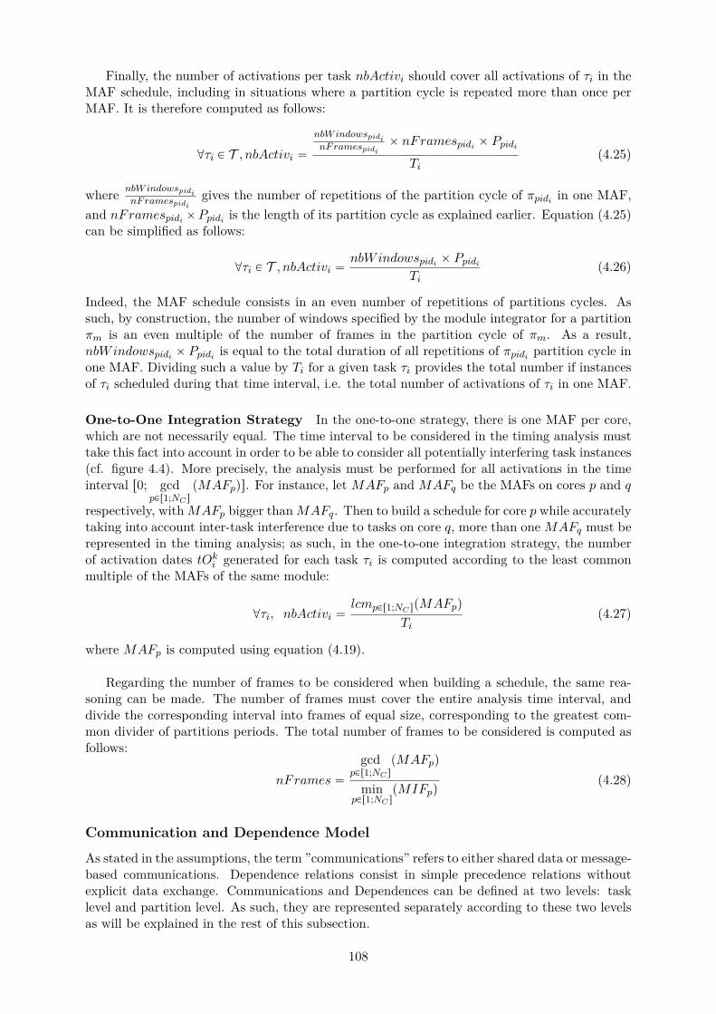
Finally, the number of activations per task nbActivi should cover all activations of τi in theMAF schedule, including in situations where a partition cycle is repeated more than once perMAF. It is therefore computed as follows:
@τi P T , nbActivi “nbWindowspidinFramespidi
ˆ nFramespidi ˆ Ppidi
Ti(4.25)
where nbWindowspidinFramespidi
gives the number of repetitions of the partition cycle of πpidi in one MAF,and nFramespidi ˆPpidi is the length of its partition cycle as explained earlier. Equation (4.25)can be simplified as follows:
@τi P T , nbActivi “nbWindowspidi ˆ Ppidi
Ti(4.26)
Indeed, the MAF schedule consists in an even number of repetitions of partitions cycles. Assuch, by construction, the number of windows specified by the module integrator for a partitionπm is an even multiple of the number of frames in the partition cycle of πm. As a result,nbWindowspidi ˆ Ppidi is equal to the total duration of all repetitions of πpidi partition cycle inone MAF. Dividing such a value by Ti for a given task τi provides the total number if instancesof τi scheduled during that time interval, i.e. the total number of activations of τi in one MAF.
One-to-One Integration Strategy In the one-to-one strategy, there is one MAF per core,which are not necessarily equal. The time interval to be considered in the timing analysis musttake this fact into account in order to be able to consider all potentially interfering task instances(cf. figure 4.4). More precisely, the analysis must be performed for all activations in the timeinterval r0; gcd
pPr1;NC spMAFpqs. For instance, let MAFp and MAFq be the MAFs on cores p and q
respectively, with MAFp bigger than MAFq. Then to build a schedule for core p while accuratelytaking into account inter-task interference due to tasks on core q, more than one MAFq must berepresented in the timing analysis; as such, in the one-to-one integration strategy, the numberof activation dates tOki generated for each task τi is computed according to the least commonmultiple of the MAFs of the same module:
@τi, nbActivi “lcmpPr1;NC spMAFpq
Ti(4.27)
where MAFp is computed using equation (4.19).
Regarding the number of frames to be considered when building a schedule, the same rea-soning can be made. The number of frames must cover the entire analysis time interval, anddivide the corresponding interval into frames of equal size, corresponding to the greatest com-mon divider of partitions periods. The total number of frames to be considered is computed asfollows:
nFrames “
gcdpPr1;NC s
pMAFpq
minpPr1;NC s
pMIFpq(4.28)
Communication and Dependence Model
As stated in the assumptions, the term ”communications” refers to either shared data or message-based communications. Dependence relations consist in simple precedence relations withoutexplicit data exchange. Communications and Dependences can be defined at two levels: tasklevel and partition level. As such, they are represented separately according to these two levelsas will be explained in the rest of this subsection.
108
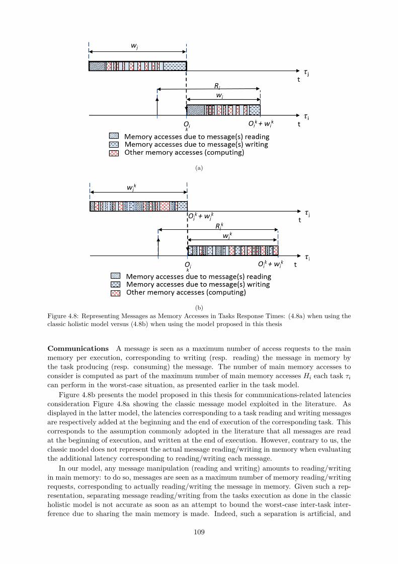
(a)
(b)Figure 4.8: Representing Messages as Memory Accesses in Tasks Response Times: (4.8a) when using theclassic holistic model versus (4.8b) when using the model proposed in this thesis
Communications A message is seen as a maximum number of access requests to the mainmemory per execution, corresponding to writing (resp. reading) the message in memory bythe task producing (resp. consuming) the message. The number of main memory accesses toconsider is computed as part of the maximum number of main memory accesses Hi each task τican perform in the worst-case situation, as presented earlier in the task model.
Figure 4.8b presents the model proposed in this thesis for communications-related latenciesconsideration Figure 4.8a showing the classic message model exploited in the literature. Asdisplayed in the latter model, the latencies corresponding to a task reading and writing messagesare respectively added at the beginning and the end of execution of the corresponding task. Thiscorresponds to the assumption commonly adopted in the literature that all messages are readat the beginning of execution, and written at the end of execution. However, contrary to us, theclassic model does not represent the actual message reading/writing in memory when evaluatingthe additional latency corresponding to reading/writing each message.
In our model, any message manipulation (reading and writing) amounts to reading/writingin main memory: to do so, messages are seen as a maximum number of memory reading/writingrequests, corresponding to actually reading/writing the message in memory. Given such a rep-resentation, separating message reading/writing from the tasks execution as done in the classicholistic model is not accurate as soon as an attempt to bound the worst-case inter-task inter-ference due to sharing the main memory is made. Indeed, such a separation is artificial, and
109

in reality, a task may as well read and/or write a message in the middle of its execution, asillustrated in figure 4.8b. The corresponding memory access requests are then issued in themiddle of the task execution, and therefore should be treated no differently than any othermemory request generated by the task during its execution when evaluating how much memoryinterference that task can suffer.
In the model we propose, the maximum number of memory accesses corresponding to read-ing/writing all messages by each task τi respectively in the software platform are computed aspart of the maximum main memory accesses τi can issue per execution, Hi. As such, Hi beingexploited to compute the worst-case interference delay τi can suffer due to sharing access tothe main memory, without making any difference whether the considered accesses are due tomessage reading/writing or pure computing, the resulting interference bound already containsa bound of the worst-case message reading/writing latency of τi per execution. The computedbounds are therefore produced independently of the origin of each memory access, exactly asillustrated in figure 4.8b.
As a consequence, the model we propose in this thesis for safely upper-bounding message-related latencies is more accurate than the classic one, and it successfully gets rid the inaccuracyof the classic holistic model when it comes to interference consideration.
We represent communications at task-level by a boolean matrix msg defined as follows:
msgij “
"
1 if i ‰ j and τi sends messages to τj ,0 otherwise (4.29)
In the one-to-one integration strategy, msg covers all tasks of the software platform and is ofsize NT ˆNT . In the one-to-all integration strategy, one matrix msg is defined per applicationsupplier asa: each corresponding matrix covers tasks of that same supplier’s applications only,and its size therefore is Nasa
T ˆNasaT . In addition, msgii is always null, as a task is assumed not
to send (resp. receive) any message to (resp. from) itself.
Inter-application communications are represented by a boolean matrix ipc, defined as follows:
ipcij “
$
&
%
1 if i ‰ j and some task belonging to πi produces data consumedby some task belonging to πj ,
0 otherwise.(4.30)
The size of ipc is NP ˆNP in both integration strategies.Finally, it is important to note that msg and ipc are unidirectional so that the producer and
consumer of each message can easily be identified respectively.
Precedence Relations Tasks may have dependences without involving explicit data ex-change. We model such precedence relations at task-level through the following boolean matrixprec:
precij “
"
1 if j ‰ i and τi is a predecessor of τj ,0 otherwise. (4.31)
As for msg, prec is of size NT ˆNT in the one-to-one integration strategy and NasaT ˆNasa
T foreach supplier asa P AS in the one-to-all integration strategy.
According to this definition, precii is always null, as a task cannot be a predecessor and asuccessor of itself.
Our model supports the expression of precedence relations between tasks of different par-titions. The corresponding partitions can correspond to the sameapplication or not. However,as mentioned in the assumptions, inter-application dependences are prohibited in IMA sys-tem. Nevertheless, no protection against an integrator exploiting our contributions and defininginter-applications dependences is implemented. The reason is to allow an integrator to guide theautomated schedule generation process by setting some partial partitions windows orderings, for
110

simplicity of management of production and consumption of messages occurring in one MAF.For the sake of simplicity of the explanations, such optional ordering preference choices are re-ferred to as precedence in the rest of this thesis even though they do not actually correspond toprecedence requirements of the system to be designed.
To represent inter-partition precedence relations, we define a following matrix pPrec asfollows:
pPrecij “
"
1 if i ‰ j and the windows of πj must occur after teh windows of πi,0 otherwise. (4.32)
The size of pPrec is NP ˆNP in both integration strategies.
Identification of Interfering Instances in a given Schedule
To be able to detect when two instances of tasks on different cores are scheduled in parallel,we define a four-dimension matrix denoted overlapping, specifying whether the execution timeinterval of τki overlaps (even partially) with the one of τmj .
Let Ikpiq ““
tOki ; tOki ` wki‰
denote the time interval in which τki is executed. Then for eachcouple of task instances τki and τmj , overlappingi,j,k,m is non-null if τi and τj are not on the samecore and their respective intervals Ikpiq and Impjq overlap in time:
@τi, τj P T ,@pk,mq P r1;nbActivis ˆ r1;nbActivjs,overlappingijkm “$
’
’
’
&
’
’
’
%
1 if pIkpiq X Impjq ‰ Hq
^
˜
NPř
r“1PARTri ˆ
NCř
p“1apr ˆ
NPř
n“1PARTnj ˆ apn “ 0
¸
,
0 otherwise.
(4.33)
As will be explained in chapter 6, overlapping is used in order to guide the schedule generationprocess towards solutions implying as less overlapping executions as possible.
4.4 Hardware Architecture Model
As illustrated in figure 4.9, we model a multicore platform with NC cores, each core p havinga clock frequency of Clkp respectively, as well as its own private cache memory, linked to themain memory via an interconnect. If all cores have the same clock frequency, the notation Clkcan be used for simplicity.
For each core p, we define CSWp as an upper bound of the cores context switch overhead:CSWp represents a maximum bound of the runtime overhead experienced when: (i) saving thecontext of a task that just finished its execution on a given core and (ii) loading the context ofthe task that will be executed right afterwards. Similarly to the cores clock frequencies, if allcores are identical or have the same context switch overhead upper-bound, the notation CSWcan be used for simplicity.
L1 Cache
As mentioned before, we assume an architecture with only one cache level private to each corep, having a total size cacheSizep in kb, consisting in nbCacheLinesp lines and an access latencyof cacheLatp ns.
The waiting delay suffered by a task τi when waiting for a data request corresponding to acache hit is accounted for in Cpi , as it is the case when using aiT Analyzer [2] for example. Allcache misses are assumed to lead to main memory accesses, and are thus accounted for in eachHki by definition. The corresponding waiting delay suffered by τi when issuing a request then
consists in (i) the delay for the request to go through the interconnect, (ii) the delay to retrieve
111
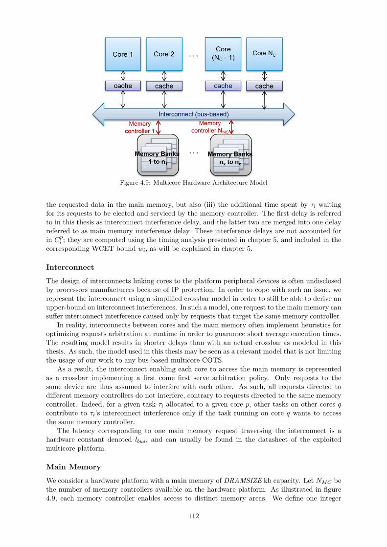
Figure 4.9: Multicore Hardware Architecture Model
the requested data in the main memory, but also (iii) the additional time spent by τi waitingfor its requests to be elected and serviced by the memory controller. The first delay is referredto in this thesis as interconnect interference delay, and the latter two are merged into one delayreferred to as main memory interference delay. These interference delays are not accounted forin Cpi ; they are computed using the timing analysis presented in chapter 5, and included in thecorresponding WCET bound wi, as will be explained in chapter 5.
Interconnect
The design of interconnects linking cores to the platform peripheral devices is often undisclosedby processors manufacturers because of IP protection. In order to cope with such an issue, werepresent the interconnect using a simplified crossbar model in order to still be able to derive anupper-bound on interconnect interferences. In such a model, one request to the main memory cansuffer interconnect interference caused only by requests that target the same memory controller.
In reality, interconnects between cores and the main memory often implement heuristics foroptimizing requests arbitration at runtime in order to guarantee short average execution times.The resulting model results in shorter delays than with an actual crossbar as modeled in thisthesis. As such, the model used in this thesis may be seen as a relevant model that is not limitingthe usage of our work to any bus-based multicore COTS.
As a result, the interconnect enabling each core to access the main memory is representedas a crossbar implementing a first come first serve arbitration policy. Only requests to thesame device are thus assumed to interfere with each other. As such, all requests directed todifferent memory controllers do not interfere, contrary to requests directed to the same memorycontroller. Indeed, for a given task τi allocated to a given core p, other tasks on other cores qcontribute to τi’s interconnect interference only if the task running on core q wants to accessthe same memory controller.
The latency corresponding to one main memory request traversing the interconnect is ahardware constant denoted lbus, and can usually be found in the datasheet of the exploitedmulticore platform.
Main Memory
We consider a hardware platform with a main memory of DRAMSIZE kb capacity. Let NMC bethe number of memory controllers available on the hardware platform. As illustrated in figure4.9, each memory controller enables access to distinct memory areas. We define one integer
112
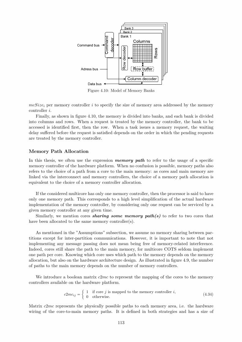
Figure 4.10: Model of Memory Banks
mcSizei per memory controller i to specify the size of memory area addressed by the memorycontroller i.
Finally, as shown in figure 4.10, the memory is divided into banks, and each bank is dividedinto columns and rows. When a request is treated by the memory controller, the bank to beaccessed is identified first, then the row. When a task issues a memory request, the waitingdelay suffered before the request is satisfied depends on the order in which the pending requestsare treated by the memory controller.
Memory Path Allocation
In this thesis, we often use the expression memory path to refer to the usage of a specificmemory controller of the hardware platform. When no confusion is possible, memory paths alsorefers to the choice of a path from a core to the main memory: as cores and main memory arelinked via the interconnect and memory controllers, the choice of a memory path allocation isequivalent to the choice of a memory controller allocation.
If the considered multicore has only one memory controller, then the processor is said to haveonly one memory path. This corresponds to a high level simplification of the actual hardwareimplementation of the memory controller, by considering only one request can be serviced by agiven memory controller at any given time.
Similarly, we mention cores sharing some memory path(s) to refer to two cores thathave been allocated to the same memory controller(s).
As mentioned in the ”Assumptions” subsection, we assume no memory sharing between par-titions except for inter-partition communications. However, it is important to note that notimplementing any message passing does not mean being free of memory-related interference.Indeed, cores still share the path to the main memory, for multicore COTS seldom implementone path per core. Knowing which core uses which path to the memory depends on the memoryallocation, but also on the hardware architecture design. As illustrated in figure 4.9, the numberof paths to the main memory depends on the number of memory controllers.
We introduce a boolean matrix c2mc to represent the mapping of the cores to the memorycontrollers available on the hardware platform.
c2mcij “
"
1 if core j is mapped to the memory controller i,0 otherwise. (4.34)
Matrix c2mc represents the physically possible paths to each memory area, i.e. the hardwarewiring of the core-to-main memory paths. It is defined in both strategies and has a size of
113
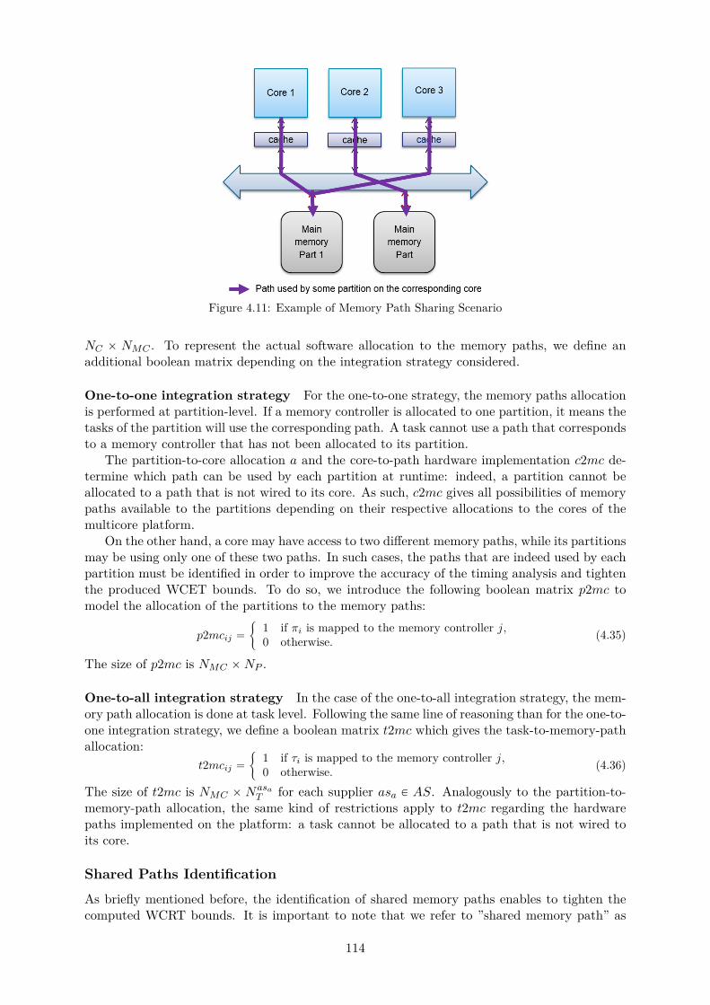
Figure 4.11: Example of Memory Path Sharing Scenario
NC ˆ NMC . To represent the actual software allocation to the memory paths, we define anadditional boolean matrix depending on the integration strategy considered.
One-to-one integration strategy For the one-to-one strategy, the memory paths allocationis performed at partition-level. If a memory controller is allocated to one partition, it means thetasks of the partition will use the corresponding path. A task cannot use a path that correspondsto a memory controller that has not been allocated to its partition.
The partition-to-core allocation a and the core-to-path hardware implementation c2mc de-termine which path can be used by each partition at runtime: indeed, a partition cannot beallocated to a path that is not wired to its core. As such, c2mc gives all possibilities of memorypaths available to the partitions depending on their respective allocations to the cores of themulticore platform.
On the other hand, a core may have access to two different memory paths, while its partitionsmay be using only one of these two paths. In such cases, the paths that are indeed used by eachpartition must be identified in order to improve the accuracy of the timing analysis and tightenthe produced WCET bounds. To do so, we introduce the following boolean matrix p2mc tomodel the allocation of the partitions to the memory paths:
p2mcij “
"
1 if πi is mapped to the memory controller j,0 otherwise. (4.35)
The size of p2mc is NMC ˆNP .
One-to-all integration strategy In the case of the one-to-all integration strategy, the mem-ory path allocation is done at task level. Following the same line of reasoning than for the one-to-one integration strategy, we define a boolean matrix t2mc which gives the task-to-memory-pathallocation:
t2mcij “
"
1 if τi is mapped to the memory controller j,0 otherwise. (4.36)
The size of t2mc is NMC ˆ NasaT for each supplier asa P AS. Analogously to the partition-to-
memory-path allocation, the same kind of restrictions apply to t2mc regarding the hardwarepaths implemented on the platform: a task cannot be allocated to a path that is not wired toits core.
Shared Paths Identification
As briefly mentioned before, the identification of shared memory paths enables to tighten thecomputed WCRT bounds. It is important to note that we refer to ”shared memory path” as
114

Figure 4.12: Core-Level Path Sharing and Runtime Interference
the sharing of the access to some memory controller, and not to the interconnect, since theinterconnect is evidently shared by all cores whatever the memory and core allocation.
According to the interference computational model presented in chapter 5, shared paths mustbe identified at core level. If two patitions (resp. tasks) which share the same path to the mainmemory have been allocated to two different cores, then these two partitions are potentiallyinterfering at runtime when issuing requests to access the main memory. The corresponding twocores are then also considered to share some path to the main memory.
It is important to note that such information is computed using partition- (resp. task-) tocore allocations, and not from matrix c2mc: we are indeed interested in paths effectively usedby cores at runtime, as given by definition by matrices p2mc and t2mc in the one-to-one andone-to-all integration strategies respectively, whereas c2mc states all physically possible pathsto the memory for each core.
An example is given in figure 4.11 with three cores and two memory paths, assuming all coresshare access to all memory controllers of the hardware platform. All terms of the correspondingmatrix c2mc would then be equal to one to signify that all cores share access to all paths. Thepurple lines represent the memory path allocation to the partitions or the tasks depending onthe implemented integration strategy, and therefore represents information contained in p2mcand t2mc. In this example, core 2 will suffer no memory interference at runtime, despite thefact that all cores are wired to both memory paths available to the memory area accessed bycore 2.
Another example is given in figure 4.12, where tasks on different cores 1 and 3 share accessto the same memory path but are never scheduled simultaneously, leading to zero inter-coreinterference during these tasks instances execution despite the fact that core 1 and 3 do shareaccess to the same paths. As such, the information to take into account during analysis is theone given by matrices p2mc and t2mc in each strategy respectively, and not the informationcontained in c2mc, which would be likely to introduce unnecessary pessimism to the tasks WCETbounds.
One-to-one integration strategy To identify memory paths shared by cores in the con-text of the one-to-one integration strategy, we define the following boolean matrix isSharingMC:
isSharingMCpq “
"
1 if p ‰ q and cores p and q share some path to the main memory,0 otherwise. (4.37)
IsSharingMC is of size NC ˆNC and can be deduced from matrices p2mc and a as follows:
isSharingMCpq “$
’
&
’
%
1 if pi ‰ jq ^
˜
NPř
i“1
NPř
j“1api ˆ aqj ˆ
ˆ
NMCř
k“1p2mcki ˆ p2mckj
˙
‰ 0¸
0 otherwise.
(4.38)
115
Indeed, if there exists at least one couple of partitions pπi, πjq allocated to cores p and q andwhich have been allocated to the same memory path k, then cores p and q host partitions thatmay interfere at runtime when simultaneously accessing the same main memory controller atruntime, and isSharingMCpq is therefore equal to one. If no such couple of partitions exists,partitions on cores p and q will not interfere with each other at runtime when trying to accessthe main memory, and isSharingMCpq is equal to zero.
One-to-all integration strategy In the one-to-all integration strategy, only one parti-tion is running at a time. An important information is then to know not only whether two coresshare some path to the memory, but also identify whether tasks of the same partition belongingto one of these two cores share some path to the memory. Indeed if the tasks of a same partitionplaced on different cores p and q do not share some memory path, then they will not cause anyinterference delay to each other, even if cores p and q use the same path to the memory for twodifferent partitions. If tasks of a same partition but allocated to different cores do not sharesome memory paths, then they will never cause memory interference to one another, even if thecores they are allocated to share some memory paths.
As such in the one-to-all integration strategy, one must define one matrix per partition inorder to identify whether simultaneous accesses to the same memory paths can occur at runtimein the windows of the corresponding partitions respectively. We define the following matrixisSharingMC:
@πm P P, isSharingMCmpq “
$
&
%
1 if i ‰ j and some tasks of πm respectively located on coresp and q share some path to the main memory,
0 otherwise.(4.39)
The size of isSharingMC is NasiP ˆNC ˆNC for each supplier asi and can be deduced from
matrices PART , t2mc and na as follows:
@πm P P, isSharingMCmpq “$
’
&
’
%
1 if p ‰ q ^
˜
NTř
i“1PARTmi.
NTř
j“1PARTmj . pnapi ˆ naqjq .
ˆ
NMCř
k“1t2mcki ˆ t2mckj
˙
‰ 0¸
0 otherwise.(4.40)
Equation (4.40) is defined using an analog reasoning to the one described for the definitionof equation (4.38). As mentioned before, the difference lays in the fact that cores and memorypaths are allocated to tasks inside partitions rather than partitions themselves, and as illustratedin figure 4.1, tasks of the same partition are scheduled on all cores at any given time. As such,inter-core interference may occur between tasks of the same partition only, which must reflecton the definition of each isSharingMCpqm element.
4.5 Constraint Programming
In this thesis, we address the design space exploration search performed when looking for asoftware/hardware allocation, and when generating a schedule configuring the runtime behaviorof the system to be designed. We propose to use constraint programming to express the allocationand scheduling problems involved in the proposed integration strategies.
Each CP defined in this thesis has one of the following two goals: generate an allocation, orgenerate a schedule. The corresponding set of constraints to be expressed in each CP depends onthe considered strategy. However, in both strategies, the same requirements must be enforced,and therefore similar types of constraints must be expressed in each CP.
116

The goal of this subsection is to briefly present the main types of constraints that willbe expressed when defining a CP for the allocation and the scheduling problems respectively.Extended details about the actual implementation of these constraints in the expressed CPs willbe given later in chapter 6. The content of this section applies to both integration strategiesproposed in this thesis.
4.5.1 Allocation Constraints
The allocation process consists in allocating the software platform – composed of partitions andtasks – onto the hardware platform – processing cores, main memory and memory paths. In theprocess of doing so, several conditions must be respected. In particular, the following categoriesof constraints are represented in all CP handling allocation concerns in both strategies proposedin this thesis:
• Proper allocation constraints: this type of constraints is focused on basic allocationconstraints, such as ensuring all partitions and tasks are allocated exactly once to a coreand at least to one memory controller. This type of constraints also includes considerationof allocation affinities and exclusion requirements, and the enforcement of the fact that allcores and memory paths must be exploited. Finally, constraints verifying the coherence ofthe evaluated allocations during the solving process are also covered (e.g. no overloadedcore, memory controller allocation coherent with the available memory space addressableby each controller respectively, etc.)
• Constraints performing a feasibility analysis: this type of constraints ensures thatthe selected allocation corresponds to a feasible system, where it will be possible to find atleast one schedule respecting all deadlines later during the schedule configuration phase.This includes the computation of tasks WCRTs and jitters, partitions CPU time budgets,etc.
• Allocation Optimization Constraints An example of allocation optimization con-straint in the one-to-one integration strategy may be a constraint stating that if twopartitions are involved in some communications, then they should be allocated to thesame core and memory controller. This is considered as an optimization constraint since itis not expressing a requirement, and it enables to reduce the amount of potential multicoreinterference occurring at runtime. Indeed, it ensures the two partitions cannot try andaccess the shared space storing the exchanged data concurrently at runtime, but ratherone after the other.Another example of optimization constraint, in the one-to-all integration strategy only, isa constraint limiting the number of shared memory controllers allocated to the tasks of thesame partition. Indeed, by construction of the one-to-all schedule (see figure 4.6), tasksinside a same partition are susceptible to interfere at runtime, whereas tasks of differentpartitions can share memory controller without causing interference to each other.
CP solvers usually allow an objective function to be defined. The main goal of such a functionis to order all valid solutions of the CP according to an optimization criteria. For instance inthe case of an allocation CP, the minimization of the CPU workload is often expressed as theobjective function. However, this does not correspond to the way CPU workload has beenhandled during the design cycle of currently existing avionics systems: a threshold value isusually set as a maximum value of CPU workload, in case additional software would be addedto the module in later design versions of the system.
This threshold value guides the design process since it corresponds to a requirement ofthe system that must be enforced. However, previously designed systems relied on single-coreplatforms; systems targeted in this thesis are multicore-based and may therefore suffer frombigger workload sensitivity than monocore-based systems.
117
In fact, a threshold CPU workload value could be enforced as a hard requirement to themulticore allocation problem using the following constraint: ”the maximum CPU utilizationratio fixed by system designers must be enforced on all cores”. However system designers usuallychoose the threshold according to experience and good knowledge of the exploited hardware andsoftware platforms.
In single-core environments, these thresholds are carefully studied and set using knowledgeand know-how based on experience (previous systems, previous hardware and software behav-iors) There exist no such knowledge and know-how in the multicore case to rely on when fixing aCPU utilization threshold. As a consequence, for the same software platform and the workloadthreshold defined for it in a monocore-based context, designers have no certainty that a solutionin a multicore environment exists.
To easily cope with such uncertainty and save time and effort spent during the allocationphase, we suggest to define an objective function aiming at minimizing as much as possible eachCPU workload, instead of defining a maximum threshold as a constraint when the existence ofsolutions respecting such a threshold is not known, and therefore taking the risk of such con-straint rejecting all solutions that could have been considered valid, leading to a CP that failsto find a solution to the allocation problem.
Other than CPU workload minimization as an objective function for the allocation CP,minimizing multicore interference, or partitions CPU time budgets, are two suitable objectivefunctions for an allocation CP as well.
4.5.2 Scheduling Constraints
The schedule generation problem consists in finding activation dates and computing time slotsto be reserved for each partition (and tasks if the partition is non-preemptive at task-level).In the process of doing so, several conditions must be respected. In particular, the followingcategories of constraints are represented in all CP handling schedule generation concerns in bothstrategies proposed in this thesis:
• Proper schedule generation constraints: this type of constraints is focused on basicschedule generation constraints, such as ensuring the order of activation dates for a giventask matches the execution instance number of the task. Another important constraint isto ensure that every activation date is an even multiple of the CPU clock, which definesthe instants when tasks are selected for execution by the OS and therefore able to startexecuting.The overall coherence of the generated schedule belongs to this type of constraints aswell: for instance, one must verify that all inter-task dependences defined in the softwareplatform are respected. The absence of overlapping executions on the same core must alsobe verified.
• Schedule verification constraints: this type of constraints embraces a schedulabilityanalysis in order to ensure all deadlines of the systems are enforced in the generatedschedule. This includes the computation of tasks WCETs, the verification that all deadlinesare enforced, but also that the corresponding partition windows are enforced.
• Schedule optimization constraints: An example of schedule optimization constraintmay be a constraint stating that if a task is not scheduled concurrently to any other taskon the other cores, then that task does not suffer from multicore interference at runtime.This is considered as an optimization constraints since multicore interference are soughtto be minimized as much as possible in general.
As for allocation problems, it is possible to define an objective function to guide the CPsearch towards optimized schedules according to a custom criteria. An objective commonly
118
chosen in the literature is the minimization of the total makespan. However, in IMA systems,it is more important to reduce as much as possible the size of partitions windows, but alsomulticore interference, than try and reduce the total makespan.
Another objective function that can be defined is to reduce as much as possible concurrentexecutions on the cores, as it reduces runtime competition of tasks trying to access the sameshared resource.
4.5.3 Why Constraint Programming
CP was chosen as the approach for applying the integration strategies proposed in this thesisbecause it matched the best the requirements and context of this thesis. Indeed, using CP enablesto focus on the problem formalization into matchematical variables and constraints, withouthaving to study which solving algorithm must be used depending on the types of equationsrepresenting the problem. CP solvers that currently exist in the literature – no matter whetherlicensed or free for use – often present capabilities of selecting the right solving algorithm adaptedto the type of equations of the expressed problem. In comparison, heuristics or user-definedalgorithms for solving the same problem may require specific knowledge of the algorithms inorder to use them properly.
Another justification lays in the portability of the usage of CP techniques. It is easy tochange the problem formulation by adding, deleting or modifying its equations. If a heuristicwas used instead, any change to the problem formulation may lead to changes to be made tothe algorithm. For instance when using a greedy algorithm such as best-fit to allocate tasksonto a multicore platform, adding allocation criteria such as energy consumption limitationmay require to code a new loop inside the algorithm for this characteristic to be taken intoaccount. When using a CP formulation, it would be enough to just add an equation expressingthe energy consumption limitation into the CP problem formulation, without having to modifythe CP solving process and/or algorithm. As such, modifications to a CP problem does notrequire modifying the CP solving process and/or algorithm. For similar reasons also, it maybe easier to move to a different CP solver than to switch heuristics for a given problem to besolved.
Finally, it is easier to optimize the solving process when using a CP formulation of a problemthat has been formalized into a mathematical representation. When the solving process is takingtoo long, one has the possibility to change the way of expressing the problem, by changing themathematical equations, adding new equations to help reduce the search space, etc. This canhardly be done when using less flexible solving approaches such as heuristics. Heuristics areusually selected in order to escape the intractability of some mathematical problems, but it ishard to optimize or help the algorithm behind the heuristic when it is stuck. At the beginningof this thesis, early work has been implemented using a heuristic named Midaco [147]. Midacoconsists in a machine learning algorithm for solving nonlinear mixed integer problems. Whilethis heuristic is able to explore large design spaces and proposes features for search optimization,one has to learn about the algorithm in order to truly benefit from these features. Eventuallyexpressing the most complicated equations, the allocation problem that had been representedbecame intractable for Midaco.
Finally, it is important to note that having selected CP as a representation of the steps ofthe integration strategies proposed in this thesis does not limit the usage of this work. To reusethe contributions of this thesis, one would have to follow one of the two approaches for SW/HWintegration described in chapter 6, which describes all the requirements that must be verified inorder to guarantee a correct runtime behavior of the system.
4.6 Discussions
This section reviews some elements presented in this chapter. More specifically, this sectiondiscusses some modeling choices that have been made when representing the system model, and
119
provides insight on the main motivation behind each choice.
One-to-All Integration Strategy: MAF cycle versus Partition Cycle. One may havenoticed that, although the MAF may be longer than each partition cycle, it suffices to use theCPU time budgets per frame Eki of each partition cycle when building a partition schedule forthe entire MAF, i.e. use a vector of size nFramesi to create time windows for πi for a MAFhaving nFrames frames.
The reason is that, in the one-to-all integration strategy, all interference are intra-partition.As such, inter-task interference – and therefore, the corresponding partition CPU time budgets– will not change depending on other partitions time windows in the schedule. The timinganalysis performed during the allocation phase has produced bounds on Eki that are valid foreach occurrence of Eki in the MAF of length gMAF . As such, the module integrator can workwith the Eki budgets, as illustrated in figure 4.7.
It may be interesting to note that each application supplier may then find out that thesebudgets could have been tightened depending on the defined windows position in the MAF, butthe computed configurations and analyses still remain safe as is. As the work in this thesisconstitutes the first basis of legacy software transfer to multicore platforms with minimizationof rework and enforcement of key certification aspects, partitions CPU time budgets value opti-mization can be considered as interesting future work for further increase design optimization.
Path Representation, Improvement of the Models Accuracy and the Tighteningof Interference Bounds. It is important to note that a software platform which does notimplement any message passing between partitions allocated ot different cores is not free ofmemory-related interference, as cores may use the same path to the main memory at runtimefor computing purposes. Knowing which core uses which path to the memory depends on thepath allocation, but also on the chip design. In the one-to-one integration strategy, the partition-to-core allocation a and the core-to-path hardware implementation c2mc determine which pathmay be used by each partition at runtime and therefore have an impact on the possible valuesof the elements of p2mc. Such information can be valuable from the timing analysis point ofview since it would enable to distinguish which tasks cannot interfere at runtime because theyare allocated to different memory paths, as illustrated in the example given in figure 4.11. Thesame can be said in the one-to-all integration strategy, with matrices na, c2mc and t2mc insteadof a, c2mc and p2mc respectively.
The knowledge of which partitions (resp. tasks) uses which main memory path is usefulto compute tight WCRT bounds: at runtime, tasks which do not share any path to the mainmemory with a task τi can be ruled out from the computation of Ri and wi. As such, althoughidentifying which partition (resp. task) is using which memory path can be used to identifywhich partitions (resp. tasks of the same partition) share some path to the main memory, andthen reject non-interfering requests from their WCRT and WCET computation.
It is important to note that it is necessary to represent both the hardware path wiring c2mcand the software path allocation p2mc (resp. t2mc). Matrix c2mc gives all possibilities of mem-ory paths available to the partitions (resp. tasks) depending on their core allocation. On onehand, a core may have access to two different memory paths, while its partitions (resp. tasks)may be using only one of these two paths. In such cases, the paths that are indeed used byeach partition (resp. task) must be identified. On the other hand, some COTS may offer onlyone path per core, and thus p2mc (resp. t2mc) can directly be derived from c2mc and the coreallocation a (resp. na). However, even in such cases p2mc still holds valuable information inour model, since it enables to distinguish potentially interfering partitions from partitions thatwill never interfere because they do not use the same path to the memory. In addition, if onlyone memory path is possible per core, then partitions (resp. tasks) involved in message commu-nications are forced to be allocated to the same core; in that case, c2mc would have influenced
120
the allocation a (resp. na), so it would still have held valuable information.
Finally, it is also important to note that memory paths are not represented in the approachin [84], which has been used as a basis for the interference analysis presented in chapter 5.As a result, interference upper-bounds computed by using the work in this thesis are likely tobe more tight that the corresponding upper-bounds produced as a result of the application ofthe approach in [84]. As such, the work we present in this thesis improves the accuracy of thehardware model exploited for deriving WCET upper bounds compared to the approach proposedin [84].
Shared Memory. When a message is produced, both the sending and the receiving parti-tions (resp. tasks) need to be able to access the memory region where the message is storedafter reception. The memory allocation an memory path allocation must take into account suchconstraints, as will be done in this thesis and explained in chapter 6.
For a given shared memory area, only the tasks of two partitions can access it: the parti-tion containing the sender task and the partition containing the receiver task of the messagefor which that shared memory has been specified. This means the shared area can potentiallybe accessed simultaneously by two tasks: one for writing in memory, and another for readingin memory. As such, sharing memory in these specific conditions generates some interferencebetween the two involved partitions. This translates at runtime into additional waiting delaythe corresponding message producer and consumer tasks can experience due to writing/readingthat message, if they simultaneously try to write/read the message in memory. Such a scenariois considered when computing the WCET of each task in order to consider to worst possiblesituation of interference due to shared resources. The corresponding interference delay sufferedby each task sending and/or receiving at least one message is accounted for in the inter-taskmemory interference delays we compute thanks to our timing analysis, as will be explained inchapter 5.
A task sending a message has a ”write only” authorization on the shared memory spaceused for storing the corresponding message. A task receiving a message has a ”read only”authorization on the shared memory space used for storing the corresponding message. Suchauthorizations can be enforced at runtime using MMUs and health monitoring recovery actionsin case of detected violations; it is important to note that MMUs are currently implemented inmost COTS multicores. Such mechanisms also ensure that there cannot exist any problem ofdata overwriting by two different tasks at runtime.
According to the IMA standard, message-based communications are formalized in two differ-ent ways. Messages are either queued or sampled. Queueing is used when a message is destroyedafter being read by the receiving task(s). Sampling is exploited in situations where a messageis refreshed or rewritten in memory, and each receiving task works with the copy available at agiven time or an old version of the message, depending on the schedule and on the specificationsof the corresponding application. Situations of unplanned and undesired message overwritingby the task sending the corresponding message are excluded by good software developmentpractices.
Either system designers decide it is not a problem, or they want to avoid such situations,in which case the shared memory space to be used for the corresponding message exchange isto be large enough to store more than one copy of the message, in order to allow for multiplecopies to be stored in memory at the same time. In the later case, additional mechanisms forproper avoidance of data overwriting is assumed to be handled accordingly by software.
121
4.7 Summary
In this chapter, we briefly introduced the two integration strategies proposed as a contributionof this thesis. Each integration strategy includes a software/hardware allocation activity, and aschedule generation activity where a static schedule is built for partitions in one MAF. Thesetwo activities include timing analyses to verify beforehand that the configuration choices thatwere made actually correspond to valid designs so that all timing requirements of the systemare guaranteed to always be respected at runtime.
Allocation and scheduling require different modelings of tasks and partitions; as such, tasksand partitions have two different representations respectively. This chapter presented all param-eters and models used in this thesis, and mentioned whether they were used for the allocationand/or the schedule generation problems.
This chapter also explained how we represent the allocation and scheduling activities as CPsin order to automate these activities, but also gain time in the design cycle of a system, andease the work of system designers and integrators. Although they could be expressed in oneformulation, the allocation and schedule generation CPs are to be solved separately: the reasonslay both in the certification requirements and the difficulty of the CP solving process. Indeed,current certification requirements imply that the allocation and the schedule generation are notperformed by the same persons. They also imply that allocation and schedule generation arenot handled as one big activity of a system design but rather in an iterative process consistingin discussions, budgets assessment and verifications by different actors. Moreover, the allocationand scheduling problems are both NP-hard on their own, which means the solving time growsexponentially with the complexity of the expressed allocation or scheduling CP. This meansthat every allocation or scheduling CP expressed in this thesis may become too difficult to besolved even separately. As such, our first attempts at defining a combined CP performing bothhe allocation and the schedule generation in one CP led to very long solving times, contrary towhen we expressed them as separate CPs.
Finally, this chapter expressed the list of constraints that must be verified either in theallocation or the schedule generation problems. Each list includes optional constraints, foroptimization purposes. The chapter then concluded with a rationale subsection about the choiceof definition of each CP formulation.
122
Chapter 5
Multicore Timing Analyses
This chapter presents the metrics proposed for performing timing analysis on multicore-basedIMA systems. As mentioned before, in current IMA systems, the timing analysis is performed attask level first, and then derived at partition level. In fact, multicore interference are analyzedat task level in order to derive a safe WCET upper-bound for each task, before computing thecorresponding partitions CPU time budget needs per partition cycle.
The first section of this chapter presents the computational model proposed in order tocompute each task WCRT and WCET in the context of IMA software and multicore archi-tectures. We then present in details our approach for upper-bounding multicore interferencedelays suffered by tasks at runtime due to sharing access to the main memory. The chapterthen describes the proposed timing-related verification to be performed respectively during theallocation selection and the schedule generation.
It is important to note that this chapter is focused on how each timing analysis metric isbuilt, without positioning them with regards to the integration strategies proposed in this thesis:this will rather be done in extended details in chapter 6.
Eventually, it is important to note that additional verification such as memory allocationor affinity/exclusion constraints are not explained in this chapter, which will rather be donein chapter 6. Although some definitions of feasibility and/or schedulability analysis in theliterature may include considerations for other resources than time, the current chapter focuseson verifications that are strictly timing-related.
Finally, unless explicitly stated, all models and equations presented in this chapter are ex-ploited in both integration strategies. The way they are used in each of them will be explainedin chapter 6.
5.1 Tasks WCRTs and WCETs Computation
This section describes the computational model proposed in this thesis for the safe WCRTand WCET upper-bounds computation. Two timing analyses are proposed for WCET upper-bounding: one for the verification of feasibility of a given allocation configuration, and one forthe verification of the enforcement of timing requirements in a given schedule configuration.Subsection 5.1.1 relates to the allocation problem, while subsection 5.1.2 relates to the schedulegeneration problem.
5.1.1 Tasks WCRTs and Allocation
The response time analysis consists in computing tasks WCRT upper-bounds and performing afeasibility analysis for a given system. To do so, the system of equations (2.3) is exploited in thecase of a preemptive environment, equation (2.4) in the case of a non-preemptive environment.
123
These systems of equations suit single-core architectures, but neither multicore nor IMAarchitectures. We present here an adaptation suited for IMA and multicore architectures.
This thesis covers both preemptive and non-preemptive task sets. This has an impact on theresponse time equations to be used during the analysis. To ease understanding of the reader, weexplain our derivations on the response time equations of preemptive tasks, before presentingthe final equations implemented that are applicable to both preemptive and non preemptivetask.
WCRT and IMA
The classic response time equations do not represent an equivalent of the IMA partition level.In IMA architectures, the partition level has an impact on tasks WCRT since each partition isallocated separate CPU time intervals in a schedule that condition which tasks are allowed torun during these intervals. In fact, a task τi can only be preempted or blocked by tasks of thesame partition,the second equation of the system (2.7) can be updated as follows:
@τi P T , wi “ C1
i `
NTÿ
j“1pidj“pidi^
τjPhppτiq
R
wi ` JjTj
V
C1
j (5.1)
where C 1i is the duration of execution of τi in isolation depending on the core it is executingon, and as defined in chapter 4 and hppτiq is the set of tasks having a higher priority than τi asdefined by equation (4.7).
Equations declined from equation (2.3) for task response time computation are often solvediteratively, Ri being a fixed point solution. Another way to solve equation (2.3) is to find thesmallest integer value which satisfies equation (2.3). In our case, we implement the second res-olution technique, by using constraint programming to define Ri as the minimum solution ofequation (2.3).
Finally, we include consideration of context switch overheads using CSW as follows:
@τi P T , wi “´
C1
i ` CSW
¯
`
NTÿ
j“1pidj“pidi^
τjPhppτiq
R
wi ` JjTj
V
´
C1
j ` CSW
¯
(5.2)
where CSW represents the overhead corresponding to context switching from the task that justfinished its execution to the next task to be scheduled, τi.
WCRT and multicore
The classic response time analysis considers that the entire task set is to be scheduled on thesame core of a single-core hardware platform. An easy transposition to multicore environmentsthat can be found in the literature is to consider each core as a separate computing resource. Thesystem can be divided into as many sub-systems as there are cores, one subsystem correspondingto a core and the partitions (resp. tasks) that are allocated onto that core. For each subsystem,the system of equations (2.7) is then expressed while considering only tasks belonging to it, andC1
i corresponds to the task duration in isolation depending on the core τi (resp. its partition) isallocated to, but also depending on the integration strategy.
In the one-to-one integration strategy, the core allocation is done using the partition-to-coreallocation matrix a. As such for each task τi, C
1
i can be computed thanks to the followingrelation:
@τi P T , C1
i “
NPÿ
j“1PARTji ˆ
˜
NCÿ
p“1apj ˆ C
pi
¸
(5.3)
124
In the one-to-all integration strategy, the core allocation is done using the task-to-core al-location matrix na. As such for each task τi, C
1
i can be computed thanks to the followingrelation:
@τi P T , C1
i “
NCÿ
p“1napi ˆ C
pi (5.4)
Ignoring additional delays appearing in practice in multicore environments limits the accu-racy of any feasibility analysis, as the computed WCRT and WCET bounds then do not actuallycorrespond to safe bounds. In this thesis, we propose an approach to safely bound such addi-tional interference delays. According to our assumptions and configuration choices (see chapter4), multicore interference is represented by concurrent accesses to the interconnect leading tothe main memory through its memory controllers.
The interconnect and main memory being used simultaneously by all active cores at run-time, additional delays do appear, and should therefore be safely taken into account in thecomputation of the WCRTs. While runtime overheads such as CSW are hardware dependentand often modeled as additional constants added to a task execution duration in isolation asdone in equation (5.2), interference delays are usually not constant over time and depend on theruntime activity of the other cores of the processor.
In the literature, interference due to shared resources is usually accounted for in the responsetime bounds by adding a sum of interference delays caused by accessing each shared resourceseparately. For instance, in the preemptive case, the updated system of equations (5.2) is thefollowing one:
@τi P T ,
$
’
’
’
&
’
’
’
%
Ri “ Ji ` wi
wi “´
C1
i ` CSW
¯
`NTř
j“1pidj“pidi^
τjPhppτiq
Q
wi`JjTj
U ´
C1
j ` CSW
¯
`#Resources
ř
k“1Ii,kpwiq (5.5)
where #Resources represents the number of shared hardware resources of the multicore con-sidered, and Ikpwiq is a maximum upper-bound of the waiting delay caused by the kth resource.As stated earlier, this thesis focuses on interference due to sharing some memory space or sim-ply sharing access to the main memory. As such, two upper-bounds of interference delays areproduced for each task τi:
• The interference due to sharing (the path to) the main memory dRAM pwi, Hpi q depending
on the task τi considered and the core p on which τi is executing,
• The interference due to sharing access to the interconnect linking the cores to the mainmemory dINT pwi, Hp
i q depending on the same parameters.
The corresponding system of equation computing an upper-bound of tasks WCRTs in mul-ticore environments is the following:
@τi P T ,
$
’
’
’
’
’
&
’
’
’
’
’
%
Ri “ Ji ` wi
wi “´
C1
i ` CSW
¯
`NTř
j“1pidj“pidi^
τjPhppτiq
Q
wi`JjTj
U ´
C1
j ` CSW
¯
`dRAM pwi, Hpi q ` dINT pwi, H
pi q
(5.6)
where p is the index of the core on which τi is executed. Detailed explanations on the imple-mented computational models to bound additional interference delays are given later in subsec-tion 5.2 of this chapter.
125
Final Tasks WCRTs and WCETs
In this thesis, both preemptive and non-preemptive partitions are taken into account, which im-pacts the equations exploited to compute the WCRTs. By exploiting isPreemptivem booleansdetermining whether a partition πm is preemptive at task level or not, we propose the follow-ing system of equations to cover both preemptive and non-preemptive cases when computingWCRTs:
@πm P P,@τi P T | pidi “ m,$
’
’
’
’
’
’
’
’
’
’
’
’
’
’
’
&
’
’
’
’
’
’
’
’
’
’
’
’
’
’
’
%
Ri “ Ji ` wi
wi “´
C1
i ` CSW
¯
`NTř
j“1pidj“pidi
τjPhppτiq
Q
wi`JjTj
U ´
C1
j ` CSW
¯
`p1´ isPreemptivemq ˆ
¨
˚
˚
˚
˚
˝
maxτjPT ztτiupidj“pidi
τjRhppτiq
´
C1
j ` CSW
¯
˛
‹
‹
‹
‹
‚
`dRAM pwi, Hpi q ` dINT pwi, H
pi q
(5.7)
where p is the index of the core on which τi is executed, C 1i is computed according to equa-tion (5.3) in the one-to-one integration strategy, (5.4) in the one-to-all integration strategy;dRAM pwi, H
pi q and dINT pwi, H
pi q respectively are upper-bounds on the worst-case interference
delay τi can suffer due to sharing access to the main memory and interconnect and are con-structed as will be explained in subsection 5.2.
At this stage, the computed bounds on tasks WCRT Ri and WCET wi suit IMA architec-tures, multicore platforms, and include safe bounds on inter-core interference.
5.1.2 Task Instances WCETs and Schedule Generation
Subsection 5.1.1 is about deriving WCRT upper-bounds for the allocation feasibility analysis.In this thesis, we also propose an approach to perform timing analysis during the schedulegeneration phase of a system design.
In IMA systems, the task-level scheduling problem is constrained by the partition level: thelatter define valid time intervals within the boundaries of which their respective tasks are allowedto be executed on the corresponding processing resource.
The analysis proposed in this thesis for the scheduling problem covers situations where tasksof a partition can be either all preemptive or all non-preemptive. The task-level WCET andschedulability analysis are performed differently depending on whether tasks are preemptive ornot.
If they are not preemptive, the schedule generation problem covers the computation of a statictask-level schedule to be enforced at runtime. In this case, the schedulability analysis coversthe verification of the enforcement of all timing requirements at task level in the computed taskschedule, but also the partition-level schedule enforcement by the task-level schedules insideeach partition respectively.
If the tasks of a partition are preemptive, the schedule generation problem rather focuseson performing a feasibility analysis for a given partition-level schedule, i.e. verifying that therewould always exist some feasible task-level schedule for a given partition-level schedule imposedat task level.
The following paragraphs present how tasks WCETs are computed in the partition-levelschedule generation phases. The approach depends on whether the considered tasks are pre-emptive or not.
126
Non-Preemptive Tasks
From the tasks point of view, the main difference between the allocation problem and theschedule generation problem is that the allocation verification focuses on the maximum WCRTeach task could have at runtime in the worst-case situation, while the schedule verificationverifies that, for a given schedule, each task instance is able to meet its deadline and dependenceconstraints. As such, in the allocation verification in the non-preemptive case, Ri is computedas if τi was scheduled after all higher priority tasks. The resulting WCET wi then contains thecorresponding delay τi spends waiting to start its execution, as expressed in the second equationof the system (5.7).
When performing the schedulability analysis, a schedule already exists, therefore it makesno sense anymore to include a delay corresponding to tasks other than τi being executed in thecomputation of its WCET wi. The following equation can then be used instead of the secondequation of the system (5.7):
@τi P T , wi “´
C1
i ` CSW
¯
` dRAM pwki , H
pi q ` dINT pw
ki , H
pi q (5.8)
where p is the index of the core on which τi is executed.
Equation (5.8) computes only one WCET to be used per task as a unique WCET upper-bound for all instances of τi in one MAF. In contrast, computing one WCET upper-bound perinstance may enable to tighten the WCET bounds for some instances, for example if they arenot scheduled in parallel with any other task on the entire multicore platform.
As will be explained in chapter 6, the proposed CPs for schedule generation are able to tighteneach WCET depending on the task instance considered. To benefit from such bound tighteningabilities, the task model for the scheduling problem – as illustrated in figure 4.4 and presentedin chapter 4 – proposed in this thesis defines one WCET upper-bound per task instance, eachtask therefore having a vector of WCET upper-bounds pw1
i , .. wnbActivii q. Equation (5.8) can
therefore be updated to compute the WCET of each task instance τki , denoted wki , as follows:
@τi P T ,@k P r1;nbActivis,
$
’
&
’
%
tOki P rpOkpidi
; pOkpidi ` Eki s where k P r1;nFramespidis | pk ´ 1qTi “ pk ´ 1qPpidi ,
wki “´
C1
i ` CSW
¯
` dRAM pwki , H
pi q ` dINT pw
ki , H
pi q
(5.9)
where p is the index of the core on which τi is executed and k P r1;nFramespidis is the index ofthe frame of the partition cycle of τi corresponding to the execution of the kth instance of τi.
Preemptive Tasks
If tasks are preemptive, a static schedule for tasks cannot be enforced at runtime since it is notpossible to determine in advance when a task is going to be preempted at runtime. However,one can perform a feasibility analysis by considering each task instance occurring in a MAF asa separate task, executing only once per MAF, and which jitter upon first activation is equal toor greater than the start of the partition window in which the instance is scheduled.
For instance, let τki be the task representing the kth instance of τi. Then τki can be consideredas a separate task having the following parameters:
• τki is scheduled only once per MAF and has a period value of a MAF.
• The jitter upon first activation of τki is greater than or equal to pOkpidi , where k P
r1;nFramespidis is the index of the window in which τki is scheduled, computed usingthe relation (5.43). For simplicity, the parameter tOki , corresponding to the task instance
127
activation date in a non-preemptive setup, is considered to represent the jitter upon firstactivation of τki in the case when τi is defined as preemptive.
• The priority of τki is equal to the priority of τi.
• The deadline of τki is equal to k ˆDi.
• The WCRT of τki is Rki .
• The WCET of τki is wki .
In such a model, the WCRT computed for each instance τki must include a term taking intoaccount the worst-case possible blocking delay suffered by this instance due to preemption byhigher priority instances τmj scheduled in the same frame as τki :
NTÿ
j“1τjPhppτiq^
pidj“pidi
nbActivjÿ
m“1pm´1qTj“pk´1qTi
S
wki ` Jmj
Tj
W
´
C1
j ` CSW
¯
(5.10)
The resulting analysis then consists in checking whether each instance WCRT respectivelyremains smaller than the corresponding instance deadline.
To sum up, if a partition tasks are preemptive, the computed schedule does not actuallycorrespond to a schedule, and neither will it be enforced at runtime on the designed system.Each task instance activation date tOki computed by a schedule generation CP then actuallycorresponds to the jitter upon activation of the kth instance of τi, and wki corresponds to theWCET of the kth instance of τi as if it were a task executed only once per MAF and which jitterupon first activation is tOki .
Such equivalence enables us to reuse the response time analysis equations for preemptivetask sets that has been presented in the system (5.7) for the computation of WCRT and WCETupper-bounds. The resulting timing analysis evaluates partition schedules for partitions withpreemptive tasks, i.e. checks whether a feasible task-level schedule could be found within theboundaries of a given partition-level schedule. The resulting equation to compute each taskinstance WCET is the following:
@τi P T ,@k P r1;nbActivis,
$
’
’
’
’
’
&
’
’
’
’
’
%
tOki P rpOkpidi
; pOkpidi ` Eki s where k P r1;nFramespidis | pk ´ 1qTi “ pk ´ 1qPpidi ,
wki “´
C1
i ` CSW
¯
`NTř
j“1τjPhppτiq^
pidj“pidi
Q
wi`JjTj
U ´
C1
j ` CSW
¯
` dRAM pwki , H
pi q ` dINT pw
ki , H
pi q
(5.11)where p is the index of the core on which τi is executed and k is the index of the frame of thepartition cycle of τi corresponding to the execution of the kth instance of τi.
Final Task Instances WCETs in the Schedule Generation Problem
The system (5.9) is exploited to compute WCETs upper-bounds for non-preemptive task in-stances, while the system (5.11) is exploited for preemptive tasks. The two systems can be com-bined into one unique system covering both situations thanks to the parameters isPreemptivepidienabling to know whether a task τi is preemptive or not. The resulting system of equations is
128

the following:
@τi P T ,@k P r1;nbActivis,
$
’
’
’
’
’
’
’
’
’
’
’
&
’
’
’
’
’
’
’
’
’
’
’
%
tOki P rpOkpidi ; pOkpidi
` Eki s where k P r1;nFramespidis | pk ´ 1qTi “ pk ´ 1qPpidi ,
wki “´
C1
i ` CSW
¯
` dRAM pwki , H
pi q ` dINT pw
ki , H
pi q
`isPreemptivepidi ˆ
¨
˚
˚
˚
˚
˝
NTř
j“1τjPhppτiq^
pidj“pidi
nbActivjř
m“1pm´1qTj“pk´1qTi
R
wki `Jmj
Tj
V
´
C1
j ` CSW
¯
˛
‹
‹
‹
‹
‚
(5.12)where p is the index of the core on which τi is executed and k P r1;nFramespidis is the index ofthe frame of the partition cycle of τi corresponding to the execution of the kth instance of τi.
where p is the index of the core on which τi is executed, C 1i is computed according to equa-tion (5.3) in the one-to-one integration strategy, (5.4) in the one-to-all integration strategy;dRAM pwi, H
pi q and dINT pwi, H
pi q respectively are upper-bounds on the worst-case interference
delay τi can suffer due to sharing access to the main memory and interconnect and are con-structed as will be explained in subsection 5.2.
At this stage, the computed bounds on tasks WCRT Ri and WCET wi suit IMA architec-tures, multicore platforms, and include safe bounds on inter-core interference.
5.2 Multicore Interference Computation
In this section, we present the model we propose to compute safe upper-bounds of inter-coreinterference. We use a bottom-up approach in order to first bound interference at core level,then derive the corresponding interference delays at task level. The corresponding implicationsat partition level will be extracted from the task level when computing each partition CPU timebudget per frame Eki , as will be explained later.
As mentioned in chapter 4, caches are private to each core, which implies the absence of inter-core cache interference. The multicore interference addressed in this thesis targets interferencedue to sharing the path from cores to the interconnect, and interference due to sharing thepath from the interconnect to the main memory space through its memory controllers. Toease explanations, the former is referred to as interconnect interference, and the latteras memory interference. In order to compute interconnect and memory interference upper-bounds for each task, we define one function per interference type, denoted in previous equationsas dRAM and dINT respectively. They are based on the hardware platform model and take asinput the tasks characteristics in order to produce a safe upper-bound of the correspondingworst-case interference delays. In the current section, we present how we built functions dRAMand dINT . These two functions are currently under evaluation, which necessitates a softwarecase study leading to a feasible schedule in which parallel executions of interfering tasks areoccurring, in order to be able to compare the measured maximum interference delays sufferedby tasks and the corresponding interference upper-bounds computed by functions dRAM anddINT .
Main Memory Interference Function, dRAM
When accessing the main memory, a task may suffer additional waiting delays at runtime dueto sharing the multicore resources with other tasks executed concurrently on other cores. Thecorresponding delay depends on the task WCET wi and the maximum number of accesses to
129
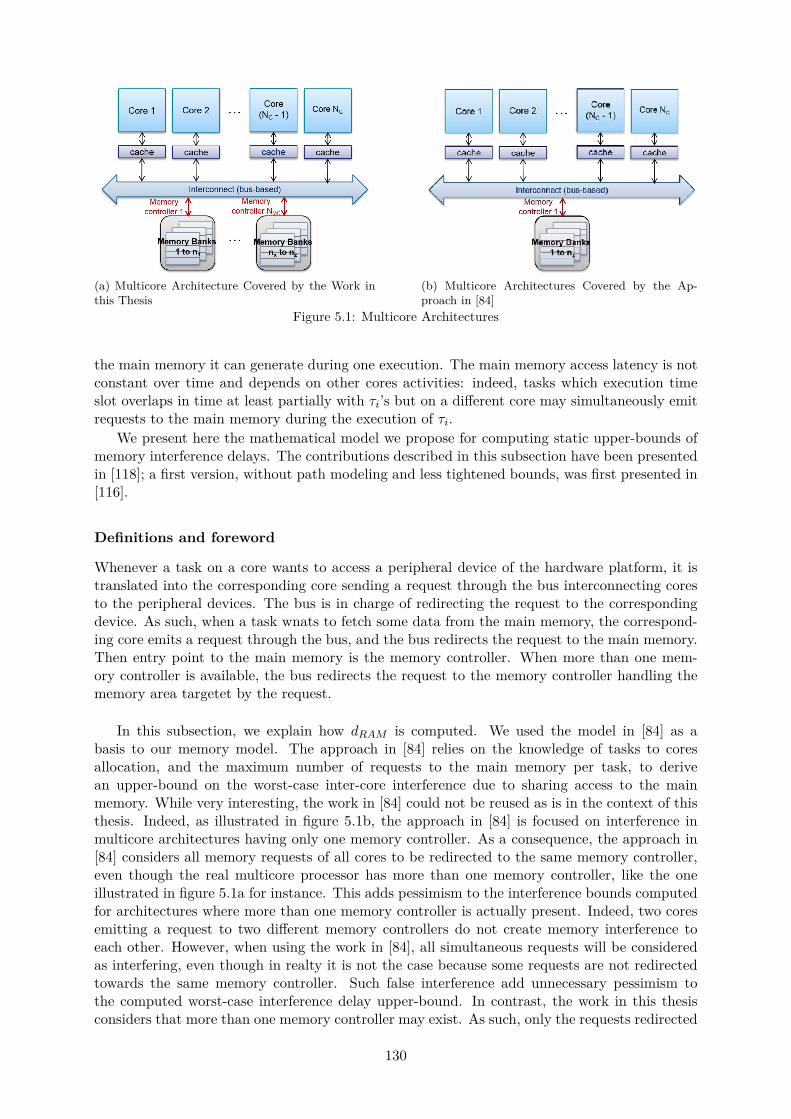
(a) Multicore Architecture Covered by the Work inthis Thesis
(b) Multicore Architectures Covered by the Ap-proach in [84]
Figure 5.1: Multicore Architectures
the main memory it can generate during one execution. The main memory access latency is notconstant over time and depends on other cores activities: indeed, tasks which execution timeslot overlaps in time at least partially with τi’s but on a different core may simultaneously emitrequests to the main memory during the execution of τi.
We present here the mathematical model we propose for computing static upper-bounds ofmemory interference delays. The contributions described in this subsection have been presentedin [118]; a first version, without path modeling and less tightened bounds, was first presented in[116].
Definitions and foreword
Whenever a task on a core wants to access a peripheral device of the hardware platform, it istranslated into the corresponding core sending a request through the bus interconnecting coresto the peripheral devices. The bus is in charge of redirecting the request to the correspondingdevice. As such, when a task wnats to fetch some data from the main memory, the correspond-ing core emits a request through the bus, and the bus redirects the request to the main memory.Then entry point to the main memory is the memory controller. When more than one mem-ory controller is available, the bus redirects the request to the memory controller handling thememory area targetet by the request.
In this subsection, we explain how dRAM is computed. We used the model in [84] as abasis to our memory model. The approach in [84] relies on the knowledge of tasks to coresallocation, and the maximum number of requests to the main memory per task, to derivean upper-bound on the worst-case inter-core interference due to sharing access to the mainmemory. While very interesting, the work in [84] could not be reused as is in the context of thisthesis. Indeed, as illustrated in figure 5.1b, the approach in [84] is focused on interference inmulticore architectures having only one memory controller. As a consequence, the approach in[84] considers all memory requests of all cores to be redirected to the same memory controller,even though the real multicore processor has more than one memory controller, like the oneillustrated in figure 5.1a for instance. This adds pessimism to the interference bounds computedfor architectures where more than one memory controller is actually present. Indeed, two coresemitting a request to two different memory controllers do not create memory interference toeach other. However, when using the work in [84], all simultaneous requests will be consideredas interfering, even though in realty it is not the case because some requests are not redirectedtowards the same memory controller. Such false interference add unnecessary pessimism tothe computed worst-case interference delay upper-bound. In contrast, the work in this thesisconsiders that more than one memory controller may exist. As such, only the requests redirected
130

towards the same memory controller are considered as interfering.Another characteristic made the approach in [84] not directly applicable to the context of
this thesis: in fact, it is not directly applicable to IMA environments. Indeed, according to theIMA architecture, two tasks executing on the same core and belonging to two different par-titions will never be able to preempt each other. These two tasks will then never be able tocause memory interference to each other as well. This situation is not covered in the approachpresented in [84], where any task of higher priority than a given task is deemed perfectly ableto preempt it at runtime. As such, the corresponding, worst-case interference delay due to thepreempting task accessing the main memory during the preemption will be accounted for in thecomputed WRCT upper-bounds, including for preempting tasks actually not able to performany preemption because it belongs to a different partition.
To sum up, while the work presented in [84] is very interesting, it relies on a system model thatis inaccurate in the context of this thesis. It does not include IMA architecture or multi-memorypath considerations, which therefore leads to WCRT upper-bounds that are overly pessimistic.To avoid introducing such unnecessary pessimism, we propose to modify some of the model’sequations in order to extend the approach to IMA systems and multicore architectures featuringmore than one memory controller.
The next subsection presents in details the approach for computing dRAM , based on modyfingthe equations first presented in [84]. The approach in [84] proposed two computation methodsfor dRAM and chooses the minimum value of the two produced bounds for each task. In thisthesis, we proceed similarly by deriving each method and then combining them to produce inter-task memory interference bounds. The maximum bounds produced thanks to the two methodswill be referred to as dRAMmethod1
and dRAMmethod2respectively.
Method 1: Request Driven Approach
The first approach computes an upper-bound on the maximum delay a request on one core cansuffer. To do so, two types of interference are considered: inter- and intra-bank interference.
Inter-bank interference For a request req issued by core p, the worst case situation happenswhen: (i) every other core issued a request just before req; (ii) none of these requests targetsthe same memory bank as req; (iii) the management of each of these requests takes the longestlatency possible, lmax – which happens when neither the row to access, nor the type of requestare the same as for the previously issued request. The computation of lmax has first beenexpressed in [84]. Although to the approach in [84] is not applicable to the systems consideredin this thesis, the definition of lmax given in [84] remains valid in our context of study since itis independent of the software architecture and solely hardware-dependent: its definition reliesonly on standard DRAM parameters that can be found in the memory’s datasheet (see [84] orappendix 9.1 for a detailed description). As such, it is not a contribution of this thesis. For adetailed explanation on the computation of lmax, interested readers are invited either to read[84] or have a look at appendix 9.1.
In the one-to-one integration strategy, the inter-bank interference delay for a request issuedby core p is computed as follows:
@p P r1;NCs, RDinterp “
ÿ
@q,q‰p^
sharedpq“∅
lmax (5.13)
where sharedpq is, as defined in [84], the set of memory banks shared by cores p and q. Inthis thesis, the sharedpq parameters are represented through a boolean matrix shared insteadof sets. This does not limit the usage of shared since all equations depending on shared in [84]rely on detecting whether the sets are empty or not, without focusing on their actual content.As a conclusion, the sets sharedpq exploited in [84] have been substituted by the corresponding
131
matrix element sharedpq in this thesis. Finally, the formal definition of shared depends on theintegration strategy considered.
In the one-to-one integration strategy, the definition of shared is the following one:
sharedpq “
"
1 if p ‰ q and cores p and q share access to some memory area,0 otherwise. (5.14)
The values of the elements of shared are deduced from matrices a and ipc. In particular,sharedpq is empty only if no partition on core q is sharing any memory area with any partitionon core p. This translates into the terms api and aqj being equal to one for all partition πibelonging to p and all partition πj belonging to q, and the term api ˆ aqj ˆ pipcij ` ipcjiq beingequal to zero for all such couple of partitions. As a consequence, the emptiness of sharedpq canbe assessed in our model as follows:
@pp, qq P r1;NCs2| p ‰ q,
sharedpq
$
’
&
’
%
“ ∅ if˜
Npř
i“1
Npř
j“1api ˆ aqj ˆ pipcij ` ipcjiq “ 0
¸
,
‰ ∅ otherwise.
(5.15)
In the one-to-all integration strategy, by construction of the task-to-core allocation, thematrix shared to be defined must enable to identify the couples of cores sharing some memoryarea, but for each partition. As such, in equation (5.13) each sharedpq set is replaced bysharedpqj , where the new variable j represents the partition to which τi belongs to. Analogouslyto the one-to-one integration strategy, sharedpqj can be deduced from matrices na and msg. Inparticular, sharedpqj is empty only if no task of πj allocated to core q is sharing some memoryarea with any other task of πj located on core p. This can be expressed as follows:
@πj P P,@pp, qq P r1;NCs2| p ‰ q,
sharedpqj
$
’
’
&
’
’
%
“ ∅ ifNTř
m“1
NTř
n“1PARTjm ˆ napm ˆ PARTjn ˆ naqn
ˆpmsgmn `msgnmq “ 0,‰ ∅ otherwise.
(5.16)
If equation (5.16) is injected in equation (5.13), one may notice that there now exists oneinter-bank interference delay RDinter
p per partition, and equation (5.13) is therefore inaccurate.As such, in the one-to-all integration strategy, we denote RDinter
p,j as the inter-bank interferencedelay suffered by core p when issuing one request to the main memory in the context of partitionπj . Equation (5.13) can then be replaced by the following equation:
@πj P P,@p P r1;NCs, RDinterp,j “
ÿ
@q,q‰p
sharedpqj“∅
lmax (5.17)
Equations (5.13) and (5.17) take into account cores q which share some memory area withcore p, according to the hardware model implemented in [84]. However, the memory model in[84] contains only one memory path, contrary to our hardware model which is able to represent– and take into account when computing interference delays – all memory paths available on amulticore platform. As such, in the example illustrated in figure 4.12, the approach in [84] wouldconsider all tasks to be interfering with each other, and therefore compute an overly pessimisticWCET upper-bound due to the production of a significant memory interference upper-bound,which should in fact be equal to zero. This is valid for both the one-to-all and the one-to-oneintegration strategies.
As such, equations (5.13) and (5.17) must be updated since the sharedpq sets do not dif-ferentiate cores that are sharing the same memory paths from cores that do not. It is also
132
important to understand that such a differentiation is not to be performed using the physicalcore-to-memory paths c2mc, but rather using the result of the partition-to-core and -memoryallocation, which leads to the identification of the paths that are actually used by the cores atruntime. Indeed, a core may be able physically to use all paths to the memory while it is usingonly one of them at runtime.
If two cores embed partitions sharing some memory space, then these two cores must sharethe same path to the main memory in order for both partitions to be able to access the corre-sponding shared space. But if two cores do not share any memory space, then two situationsare possible: either the two cores share some path to the memory, or they do not. If they donot share some memory path, then they will never interfere at runtime since they do not usethe same paths, and as a consequence, such cores should not be taken into consideration whencomputing the memory interference of each other’s tasks.
This is not done in the approach of Kim et al. [84]. In contrast, to do so in this thesis, weupdate equations (5.13) and (5.17) to take into account only cores sharing the same paths tothe main memory by exploiting the boolean matrix isSharingMC. This matrix is built usingthe partitions (resp. tasks) allocation to identify the paths actually used by each core and thenidentify which couples of cores share the same memory paths at runtime. For the one-to-oneintegration strategy, equation (5.13) is updated as follows:
@πj P P,@p P r1;NCs, RDinterp,j “
ÿ
@q,q‰p
sharedpq“∅
isSharingMCpq ˆ lmax (5.18)
whereas for the one-to-all integration strategy, equation (5.17) is updated as follows:
@πj P P,@p P r1;NCs, RDinterp,j “
ÿ
@q,q‰p
sharedpqj“∅
isSharingMCjpq ˆ lmax (5.19)
Eventually, it is important to note that such usage of isSharingMC to exclude cores thatdo not share the same memory path from the memory interference computation of another coreis required in the rest of this thesis every time the sharedpq sets intervene in some equations.
Intra-bank interference When requests to the same bank as req are issued, the longestinterference delay suffered by a memory access request req to be serviced happens when: (i)every other core q that shares access to the same bank as core p emitted a request that is servicedby the memory controller before req; (ii) all these requests target a different row; (iii) a memoryrefresh – or requests reordering – is happening. If L is the delay to open a row before accessinga column, then the worst-case delay per such request is L`RDinter
q . As for lmax, the definitionof L expressed by Kim et al. in [84] remains valid in our context of study since it is independentof the software architecture model and solely hardware-dependent: its definition relies only onstandard DRAM parameters that can be found in the memory’s datasheet (see [84] or appendix9.1 for a detailed description). As such, it is not a contribution of this thesis. For a detailedexplanation on the computation of L, interested readers are invited either to read [84] or havea look at appendix 9.1.
In the one-to-one integration strategy, the intra-bank interference delay suffered by req issuedby a core p is thus:
@p P r1;NCs, RDintrap “ reorderppq `
ÿ
@q,q‰p
sharedpq‰∅
pL`RDinterq q (5.20)
Reorderppq computes an upper-bound of the maximum delay suffered by a memory requestreq due to the reordering effect. For the same reasons as for lmax and L, the computation ofreorderppq has first been expressed in [84] and the given definition remains valid in our contextof study. It is therefore not a contribution of this thesis; as such, for a detailed explanation
133
of reorderppq’s definition, interested readers are invited either to read [84] or have a look atappendix 9.1.
The definition of RDintrap must take into account the hardware model refinement proposed
as a contribution of this thesis. Indeed, the definition proposed in [84] must be modified inorder to take into account cores q that share some memory path with core p. In the one-to-oneintegration strategy, the corresponding equation is the following:
@p P r1;NCs,RDintra
p “ reorderppq `ř
@q,q‰p
sharedpq‰∅
isSharingMCpq ˆ pL`RDinterq q (5.21)
For the one-to-all integration strategy, the corresponding equation is the following:
@πj P P,@p P r1;NCs,RDintra
p,j “ reorderppq `ř
@q,q‰p
sharedpqj‰∅
isSharingMCpq ˆ pL`RDinterq q (5.22)
Finally, the total maximum interference delay RDp that a request originating from core pcan experience is computed as follows in the one-to-one integration strategy:
@p P r1;NCs, RDp “ RDinterp `RDintra
p (5.23)
In the one-to-all integration strategy, the maximum delay suffered by a request emitted by corep actually depends on the partition executed during the emission of the request:
@πj ,@πj P P,@p P r1;NCs, RDp,j “ RDinterp,j `RDintra
p,j (5.24)
Each task τi of core p having Hpi requests to issue, the total maximum interference delay
directly caused by issuing these requests is bounded by the number of requests Hpi multiplied
by the maximum delay of one request: RDp in the one-to-one integration strategy, RDp,pidi inthe one-to-all integration strategy. In addition, the cost of memory requests of tasks with higherpriorities than τi has also to be accounted for: either the corresponding partition is preemptiveat task-level, in which case the requests of all tasks with higher priorities than τi extend thedelay during which τi is preempted and waits to resume its execution; or the task-level is non-preemptive, in which case the additional delay corresponds to the requests emitted by higherpriority tasks blocking τi’s execution.
In the end, in the one-to-one integration strategy, a maximum bound on the memory in-terference delay a task τi P T allocated to core p P r1;NCs can experience is computed asfollows:
drammethod1pwi, Hpi q “ Hp
i ˆRDp
`NPř
m“1PARTmi ˆ
¨
˚
˚
˚
˚
˝
isPreemptivem ˆ
¨
˚
˚
˚
˚
˝
NTř
j“1τjPhppτiq^
pidj“pidi
Q
wi`JjTj
U
Hpj ˆRDp
˛
‹
‹
‹
‹
‚
˛
‹
‹
‹
‹
‚
`NPř
m“1PARTmi ˆ
¨
˚
˚
˚
˚
˝
p1´ isPreemptivemq ˆNTř
j“1τjPhppτiq^
pidj“pidi
Hpj ˆRDp
˛
‹
‹
‹
‹
‚
(5.25)
134

where p is the index of the core on which τi is scheduled. In the one-to-all integration strategy,the corresponding equation is the following:
dRAMmethod1pwi, H
pi q “
NPř
m“1PARTmi ˆ pH
pi ˆRDp,mq
`NPř
m“1PARTmi ˆ
¨
˚
˚
˝
isPreemptivem ˆ
¨
˚
˚
˝
ř
@j,τjPhppτiq
pidj“pidi
Q
wi`JjTj
U
Hpj ˆRDp,m
˛
‹
‹
‚
˛
‹
‹
‚
`NPř
m“1PARTmi ˆ
¨
˚
˚
˝
p1´ isPreemptivemq ˆř
@j,τjPhppτiq
pidj“pidi
Hpj ˆRDp,m
˛
‹
‹
‚
(5.26)
where p is the index of the core on which τi is scheduled.
Method 2: Job Driven Approach
The second method of computation of dramipq focuses on how many interfering memory requestsper core are generated during the execution of τi; the time interval to consider is thus wi. Itmay be interesting to note that the authors of [84] used Ri in their approach, since their modeldid not represent jitters upon activation, contrary to the work in this thesis.
The maximum number of requests Appwiq generated by a core p during a time interval oflength wi is computed as follows:
@τi P T ,@p P r1;NCs, Appwi, Hiq “
NTÿ
j“1
R
wi ` JjTj
V
Hpj (5.27)
Equation (5.27) is valid for both integration strategies. It is important to note that p is notnecessarily the index of the core on which τi is located yet.
Inter-bank interference The inter-bank interference a task τi located on a core p can sufferduring its execution can be computed by multiplying the maximum number of generated requestsby the maximum delay possible to serve a request to the same bank as req. For the one-to-oneintegration strategy for example, the corresponding interference delay is computed as follows:
@τi P T , JDinterp pwi, H
pi q “
NCÿ
q“1q‰p^
sharedpq“∅
Aqpwi, Hpi q ˆ lmax (5.28)
where, this time, p is the index of the core where τi is located.Thanks to our models, equation (5.28) can be further refined to include knowledge on the
memory path sharing by the cores, and thus reduce the pessimism of the final WCRT bound.In fact, the activity on core q only interfere during τi’s execution if there exists a partition (inthe one-to-one integration strategy) or task of the same partition (in the one-to-all integrationstrategy) allocated to core q which shares some memory path with τi. Otherwise, core q must beignored when computing τi’s memory interference delay. Therefore equation (5.28) is modifiedas follows in the one-to-one integration strategy:
@τi P T , JDinterp pwi, H
pi q “
NCÿ
q“1q‰p^
sharedpq“∅
isSharingMCpq ˆAqpwi, Hpi q ˆ lmax (5.29)
where p is the index of the core onto which τi is allocated.
135

In an analogous way for the one-to-all integration strategy, intra-bank interference sufferedby a request req can be computed using the following equation:
@τi P T ,
JDinterp pwi, H
pi q “
NCř
q“1q‰p^
sharedpqi“∅
isSharingMCp q pidi ˆAqpwi, Hpi q ˆ lmax (5.30)
where p is the index of the core on which τi is scheduled.
Intra-bank Interference The maximum intra-bank interference τi P T can suffer duringits execution when allocated to core p P r1;NCs can be computed as follows in the one-to-oneintegration strategy:
JDintrap pwi, H
pi q “
NCÿ
q“1q‰p^
sharedpq‰∅
Aqpwi, Hpi q ˆ L` JD
interq pwi, H
pi q (5.31)
In the one-to-one strategy, similarly to JDinterp ’s refinement, JDintra
p can be further tightenedby considering only cores containing partitions sharing some memory path with τi:
JDintrap pwi, H
pi q “
NCř
q“1q‰p^
sharedpq‰∅
isSharingMCpq ˆAqpwi, Hpi q ˆ L` JD
interq pwi, H
pi q (5.32)
where p is the index of the core on which τi is scheduled.In a similar way, in the one-to-all integration strategy, the intra-bank interference of a request
generated by a task τi belonging to a partition πj is derived as follows:
@πj P P | pidi “ j,
JDintrap,j pwi, H
pi q “
NCř
q“1q‰p^
sharedpqj‰∅
isSharingMCjpq ˆAqpwi, Hpi q ˆ L` JD
interq,j pwi, H
pi q (5.33)
where p is the index of the core on which τi is scheduled.
Finally, if τi is located on core p, then a maximum bound of τi’s memory interference is givenby equation (5.34) in the one-to-one integration strategy.
@τi P T , dRAMmethod2pwi, H
pi q “ JDinter
p pwi, Hpi q ` JD
intrap pwi, H
pi q (5.34)
where p is the index of the core on which τi is executed. In the one-to-all integration strategyhowever, the following equation is used instead:
@τi P T ,
dRAMmethod2pwi, H
pi q “
NPř
m“1PARTmi ˆ
`
JDinterp,m pwi, H
pi q ` JD
intrap,m pwi, H
pi q˘ (5.35)
where p is the index of the core on which τi is scheduled.
136
Final Memory Access Delay Function
Methods 1 and 2 being about the computation of maximum bounds, drami is set to the lesspessimistic of the two:
@τi P T , dRAM pwi, Hpi q “ minpdRAMmethod1
pwi, Hpi q, dRAMmethod2
pwi, Hpi qq (5.36)
where p is the index of the core on which τi is executed. During the WCRT analysis, p iscomputed using either matrix a in the one-to-one integration strategy, or na in the one-to-allintegration strategy.
In the one-to-all integration strategy, equation (5.36) is replaced by the following one:
@τi P T , dRAM pwi, Hpi q “
NCř
p“1napi ˆ
´
minpdRAMmethod1pwi, H
pi q, dRAMmethod2
pwi, Hpi qq
¯ (5.37)
where p is the index of the core on which τi is executed.In the one-to-one integration strategy, equation (5.36) is updated as follows:
@τi P T , dRAM pwi, Hpi q “
NPř
m“1PARTmi ˆ
NCř
p“1apm ˆ
´
minpdRAMmethod1pwi, H
pi q, dRAMmethod2
pwi, Hpi qq
¯ (5.38)
where p is the index of the core on which τi is executed.Eventually, the so defined dRAM pq function can be exploited with tasks respective WCETs
wi during the allocation feasibility analysis, or with task instances respective WCETs wki duringthe schedulability analysis.
Interconnect Interference Function, dINT
The worst-case interference a task τi can suffer due to accessing the interconnect linking thecores to the main memory is upper-bounded via the usage of dINT pq.
Crucial information to be able to accurately represent the interconnect through a functiondINT is often undisclosed by processors manufacturers because of IP protection. In order tocope with such an issue, we represent the interconnect using a simplified crossbar model in orderto still be able to derive an upper-bound on interconnect interferences. In such a model, onerequest to the main memory can suffer interconnect interference caused only by requests thattarget the same memory controller. As such, for a given task τi allocated to a given core p,other tasks on other cores q contribute to τi’s interconnect interference only if the task runningon core q requests access to the same memory controller.
Such situation can be identified clearly thanks to matrix overlapping during the schedulegeneration problem, but not during the allocation. As such, the computation of dINT differsslightly depending on which activity – allocation or schedule generation – is considered. It alsodepends on the integration strategy implemented.
Allocation. In the allocation problem, an upper-bound on tasks interconnect interference iscomputed using the number of cores that share access to the same memory path. For a giventask, the worst-case situation is consider to be the one where all other cores sharing access tothe same memory controller to have issued a request to that controller, and the correspondingrequest to be serviced before any request emitted by that task to the memory controller.
In the one-to-one integration strategy, the corresponding delay is computed as follows:
@τi P T , dINT pwiq “NCÿ
p“1ap,pidi ˆ
¨
˚
˝
lbus ˆNCÿ
q“1q‰p
isSharingMCpq
˛
‹
‚
(5.39)
137
In the one-to-all integration strategy, the equation is similar but based on na:
@τi P T , dINT pwiq “NCÿ
p“1napi ˆ
¨
˚
˝
lbus ˆNCÿ
q“1q‰p
isSharingMCp,q,pidi
˛
‹
‚
(5.40)
Scheduling. In the schedule generation problem, the interconnect interference is computedfor a given schedule, where task instances execution intervals are known. As such, it is possibleto take such knowledge into account in order to isolate cores where potential interference canactually occur during the execution of a given task instance τki when computing its interferencedelay due to sharing the interconnect.
In our model, it is possible to do so using matrix overlapping defined in equation (4.33) (seechapter 4). The corresponding interconnect interference delay for the schedulability analysiscorresponds to a refinement of the interference delay computed during the allocation phase:thanks to matrix overlapping, only cores sharing access to the same memory paths which scheduleat least one task instance, also allocated to the corresponding controller, in parallel of τi.
In the one-to-one integration strategy, the interconnect interference delay for the schedula-bility analysis is computed as follows for each task τi:
@τi P T , dINT pwiq “
NCř
p“1ap,pidi ˆ lbus ˆ
NCř
q“1q‰p
¨
˚
˝
NTř
j“1j‰i
aqj ˆnbActivj
ř
l“1overlappingi,j,k,l ˆ isSharingMCpq
˛
‹
‚
(5.41)
In the one-to-all integration strategy, the corresponding equation is the following:
@τi P T , dINT pwiq “NCř
p“1napi ˆ lbus
ˆNCř
q“1q‰p
¨
˚
˚
˚
˝
NTř
j“1j‰i
pidj“pidi
naqj ˆnbActivj
ř
l“1overlappingi,j,k,l ˆ isSharingMCp,q,pidi
˛
‹
‹
‹
‚
(5.42)
Eventually, the so defined dINT pq functions in the one-to-one and one-to-all integrationstrategies can be exploited with tasks respective WCETs wi during the allocation feasibilityanalysis, or with task instances respective WCETs wki during the schedulability analysis.
5.3 Partitions CPU Time Budgets Computation
This section presents how IMA partitions CPU time budgets are computed in this thesis. Asmentioned in chapter 4, each partition cycle can be divided into nFramesi frames, the kth framerequiring a CPU time budget of Eki for its tasks execution.
As such, for each partition πi and frame k P r1;nFramesis, the value of Eki must correspondto enough CPU time for all tasks of πi scheduled in the kth frame to start and complete theirrespective executions within the boundaries of the kth window of πi. Eki being the duration ofthat window, it must take into account the worst-case multicore interference delays that thetasks of πi scheduled in the kth window may suffer.
On the other hand, a task τj belonging to πi is scheduled in the kth frame if the followingrelation is verified:
pk ´ 1q ” 0 modˆ
nFramesinbActivj
˙
(5.43)
If equation (5.43) is verified, then the execution of a task τj belonging to πi during the kthframe must be taken into account in the budget Eki . To do so, the amount of time corresponding
138
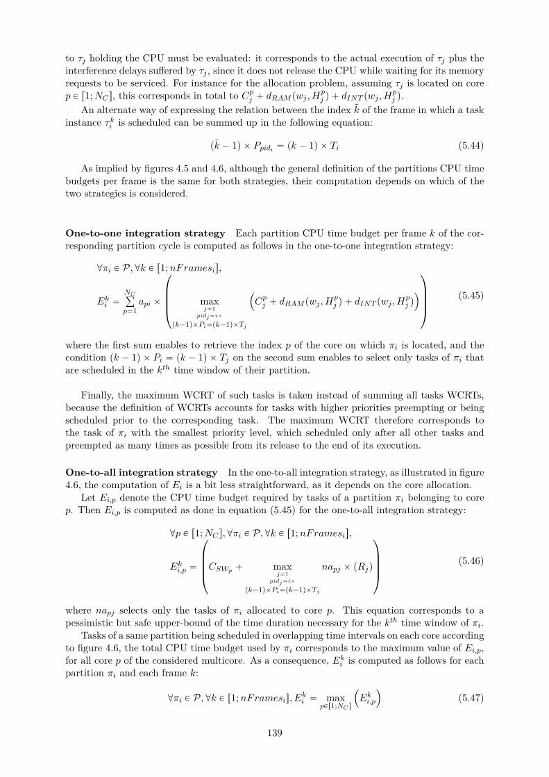
to τj holding the CPU must be evaluated: it corresponds to the actual execution of τj plus theinterference delays suffered by τj , since it does not release the CPU while waiting for its memoryrequests to be serviced. For instance for the allocation problem, assuming τj is located on corep P r1;NCs, this corresponds in total to Cpj ` dRAM pwj , H
pj q ` dINT pwj , H
pj q.
An alternate way of expressing the relation between the index k of the frame in which a taskinstance τki is scheduled can be summed up in the following equation:
pk ´ 1q ˆ Ppidi “ pk ´ 1q ˆ Ti (5.44)
As implied by figures 4.5 and 4.6, although the general definition of the partitions CPU timebudgets per frame is the same for both strategies, their computation depends on which of thetwo strategies is considered.
One-to-one integration strategy Each partition CPU time budget per frame k of the cor-responding partition cycle is computed as follows in the one-to-one integration strategy:
@πi P P,@k P r1;nFramesis,
Eki “NCř
p“1api ˆ
¨
˚
˚
˚
˝
maxj“1
pidj“i^
pk´1qˆPi“pk´1qˆTj
´
Cpj ` dRAM pwj , Hpj q ` dINT pwj , H
pj q
¯
˛
‹
‹
‹
‚
(5.45)
where the first sum enables to retrieve the index p of the core on which πi is located, and thecondition pk ´ 1q ˆ Pi “ pk ´ 1q ˆ Tj on the second sum enables to select only tasks of πi thatare scheduled in the kth time window of their partition.
Finally, the maximum WCRT of such tasks is taken instead of summing all tasks WCRTs,because the definition of WCRTs accounts for tasks with higher priorities preempting or beingscheduled prior to the corresponding task. The maximum WCRT therefore corresponds tothe task of πi with the smallest priority level, which scheduled only after all other tasks andpreempted as many times as possible from its release to the end of its execution.
One-to-all integration strategy In the one-to-all integration strategy, as illustrated in figure4.6, the computation of Ei is a bit less straightforward, as it depends on the core allocation.
Let Ei,p denote the CPU time budget required by tasks of a partition πi belonging to corep. Then Ei,p is computed as done in equation (5.45) for the one-to-all integration strategy:
@p P r1;NCs,@πi P P,@k P r1;nFramesis,
Eki,p “
¨
˚
˚
˚
˝
CSWp ` maxj“1
pidj“i^
pk´1qˆPi“pk´1qˆTj
napj ˆ pRjq
˛
‹
‹
‹
‚
(5.46)
where napj selects only the tasks of πi allocated to core p. This equation corresponds to apessimistic but safe upper-bound of the time duration necessary for the kth time window of πi.
Tasks of a same partition being scheduled in overlapping time intervals on each core accordingto figure 4.6, the total CPU time budget used by πi corresponds to the maximum value of Ei,p,for all core p of the considered multicore. As a consequence, Eki is computed as follows for eachpartition πi and each frame k:
@πi P P,@k P r1;nFramesis, Eki “ maxpPr1;NC s
´
Eki,p
¯
(5.47)
139

5.4 Allocation and Timing-Related Verification
This section presents the timing analysis performed during the allocation search. The goal ofsuch an analysis is to ensure that a given software/hardware allocation corresponds to a schedu-lable system. The task and partition models for the allocation verification (see chapter 4) areused during this analysis.
The proposed timing-related verification can be divided into two-level: task-level verification,and partition-level verification. Unless explicitly stated, all equations presented in this sectionare valid in both the one-to-one and the one-to-all integration strategies.
Task-level Timing Verification during the Allocation
The goal of the task-level verification is to compute tasks WCRT for a given software/hardwareallocation, and verify whether the computed values are smaller than the corresponding deadlines.As such, the software/hardware allocation is exploited as an input to the analysis in order tocompute the respective values of the parameters Ri, wi and Ji for each task τi as outputs.While Ri and wi are computed using the system of equation (5.7), Ji must be determinedaccording to the dependences defined in the software platform, as will be explained in the nextparagraphs. Finally, another output of the task-level verification are the partitions CPU timebudgets required per frame Ekj , computed as explained in the previous section.
Dependences. Let τi P T be a task of the software platform. Ji depends on the precedencerelations and communications τi is involved in. In fact, the predefined dependences of the systemconstraints the value of Ji, which must be taken into account when computing the WCRT of τi.
If τi does not have any predecessor nor receives any message at runtime, its jitter is null.
@τi P T |
˜
NTÿ
j“1msgji ` precji “ 0
¸
, Ji “ 0 (5.48)
On the contrary, if τi has some predecessor, its first activation can happen only after theend of the first execution of all its predecessors, as defined by matrix prec. In the one-to-oneintegration strategy, this corresponds to verifying the following relation:
Ji ě maxkPr1;NT sztiu | precki‰0
pJk ` wkq (5.49)
The analog relation is defined in the one-to-all integration strategy, by replacing NT by #T asafor each supplier asa P AS.
Similarly, the first activation of τi can happen only after the end of the first execution ofall the tasks it is receiving messages from, which implies the following relation to be verified inaddition to equation (5.49) if τi has some predecessors. In the one-to-one integration strategy,this corresponds to verifying the following relation:
Ji ě maxkPr1;NT sztiu|msgki‰0
pJk ` wkq (5.50)
The analog relation is defined in the one-to-all integration strategy, by replacing NT by #T asafor each supplier asa P AS.
It is important to note that equations (5.48), (5.49) and (5.50) concern intra-applicationprecedence and communications since matrices msg and prec are expressed by each applica-tion supplier and only mention the partitions they are respectively in charge of designing. Theverification of inter-partition precedences and communications is part of the partition-level ver-ification performed during the allocation. As will be explained in the next subsections, such averification will be done using matrices ipc and pPrec instead of msg and prec respectively.
140

Finally, it is important to note that in the feasibility analysis, the jitter upon first activationof the tasks targets only the first activation of each task; as such, equations (5.49) and (5.50)hold even in cases of multiperiodic precedence relations or communications.
Tasks Schedulability. Once jitters upon first activation and WCRTs are computed, the fea-sibility of the allocation under study is assessed by evaluating whether all tasks are schedulableor not. The software/hardware allocation can be considered as a valid allocation if all tasks areable to respect their deadlines in the worst-case situation represented by Ri, i.e. if the followingrelation is satisfied by all tasks of the software platform:
@τi P T , Ri ď Di (5.51)
If it is not the case, the allocation considered as input to the analysis is rejected as an invalidconfiguration that cannot be used for the system to be designed.
Partition-Level Timing Verification during the Allocation
Partition-level verification conducted during the allocation phase targets all dependences be-tween different partitions or applications on the same multicore.
The partition-level timing verification during the allocation consists in verifying that, for agiven allocation, it will always be possible to find a schedule where:
• All CPU time budgets of a partition πi guarantees enough time to each of its tasks ac-cording to their respective WCRTs, while meeting their periodicity requirement Pi;
• All partitions are able to satisfy such a first requirement during one MAF;
• All partition-level dependences defined in the software platform are respected. The firsttwo requirements are about the feasibility of the partitions, while the last requirement isabout dependences enforcement.
In order to perform such a verification, the MAF must be computed using all software applica-tions partitions periods information. On the other hand, all partitions CPU time budgets perframe must be computed using their respective tasks WCRTs – which are computed during thetask-level timing verification of the allocation. As such, the allocation and the tasks WCRTs areinputs to the partition-level timing analysis, along with the partitions and tasks characteristics;the MAF and the partitions CPU time budgets per frame Eki are outputs of the analysis.
The MAF is computed using equation (4.19) for each core in the one-to-one integrationstrategy, and equation (4.15) in the one-to-all integration strategy. Each partition CPU timebudget per frame Eki is computed using equation (5.45) in the one-to-one integration strategy,and equation (5.47) in the one-to-all integration strategy.
Dependences. At partition-level, the verification of inter-partition dependences must be done.In particular, partitions jitters must be defined so that the first window of a partition occurslater than the first window of all its predecessors in the MAF schedule .
Let πi P P be a partition of the software platform. If πi has some predecessors, its jittermust verify the following relation:
pJi ě maxkPr1;NP sztiupPrecki‰0
`
pJk ` E1k
˘
(5.52)
Indeed, pJi defining the jitter of the first window of πi, it must be defined such that the firstwindow of πi occurs only after the first window of all its predecessors πk, represented by theirjitters pJk and their first budgets E1
k respectively.
141
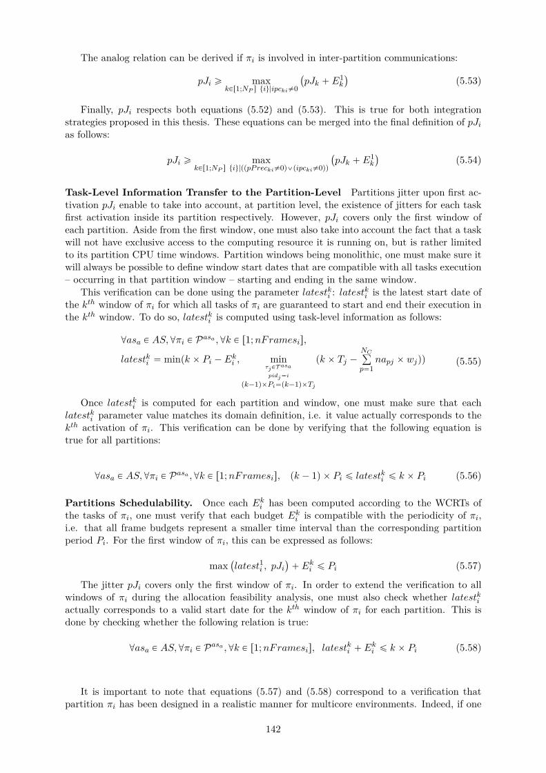
The analog relation can be derived if πi is involved in inter-partition communications:
pJi ě maxkPr1;NP s tiu|ipcki‰0
`
pJk ` E1k
˘
(5.53)
Finally, pJi respects both equations (5.52) and (5.53). This is true for both integrationstrategies proposed in this thesis. These equations can be merged into the final definition of pJias follows:
pJi ě maxkPr1;NP s tiu|pppPrecki‰0q_pipcki‰0qq
`
pJk ` E1k
˘
(5.54)
Task-Level Information Transfer to the Partition-Level Partitions jitter upon first ac-tivation pJi enable to take into account, at partition level, the existence of jitters for each taskfirst activation inside its partition respectively. However, pJi covers only the first window ofeach partition. Aside from the first window, one must also take into account the fact that a taskwill not have exclusive access to the computing resource it is running on, but is rather limitedto its partition CPU time windows. Partition windows being monolithic, one must make sure itwill always be possible to define window start dates that are compatible with all tasks execution– occurring in that partition window – starting and ending in the same window.
This verification can be done using the parameter latestki : latestki is the latest start date ofthe kth window of πi for which all tasks of πi are guaranteed to start and end their execution inthe kth window. To do so, latestki is computed using task-level information as follows:
@asa P AS,@πi P Pasa ,@k P r1;nFramesis,
latestki “ minpk ˆ Pi ´ Eki , minτjPT asapidj“i
pk´1qˆPi“pk´1qˆTj
pk ˆ Tj ´NCř
p“1napj ˆ wjqq (5.55)
Once latestki is computed for each partition and window, one must make sure that eachlatestki parameter value matches its domain definition, i.e. it value actually corresponds to thekth activation of πi. This verification can be done by verifying that the following equation istrue for all partitions:
@asa P AS,@πi P Pasa ,@k P r1;nFramesis, pk ´ 1q ˆ Pi ď latestki ď k ˆ Pi (5.56)
Partitions Schedulability. Once each Eki has been computed according to the WCRTs ofthe tasks of πi, one must verify that each budget Eki is compatible with the periodicity of πi,i.e. that all frame budgets represent a smaller time interval than the corresponding partitionperiod Pi. For the first window of πi, this can be expressed as follows:
max`
latest1i , pJi˘
` Eki ď Pi (5.57)
The jitter pJi covers only the first window of πi. In order to extend the verification to allwindows of πi during the allocation feasibility analysis, one must also check whether latestkiactually corresponds to a valid start date for the kth window of πi for each partition. This isdone by checking whether the following relation is true:
@asa P AS,@πi P Pasa ,@k P r1;nFramesis, latestki ` Eki ď k ˆ Pi (5.58)
It is important to note that equations (5.57) and (5.58) correspond to a verification thatpartition πi has been designed in a realistic manner for multicore environments. Indeed, if one
142
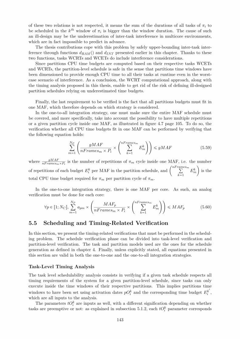
of these two relations is not respected, it means the sum of the durations of all tasks of πi tobe scheduled in the kth window of πi is bigger than the window duration. The cause of suchan ill-design may be the underestimation of inter-task interference in multicore environments,which are in fact impossible to predict in advance.
The thesis contributions cope with this problem by safely upper-bounding inter-task inter-ference through functions dRAM pq and dINT presented earlier in this chapter. Thanks to thesetwo functions, tasks WCRTs and WCETs do include interference considerations.
Since partitions CPU time budgets are computed based on their respective tasks WCETsand WCRTs, the partition-level schedule is safe in the sense that partitions time windows havebeen dimensioned to provide enough CPU time to all their tasks at runtime even in the worst-case scenario of interference. As a conclusion, the WCRT computational approach, along withthe timing analysis proposed in this thesis, enable to get rid of the risk of defining ill-designedpartition schedules relying on underestimated time budgets.
Finally, the last requirement to be verified is the fact that all partitions budgets must fit inone MAF, which therefore depends on which strategy is considered.
In the one-to-all integration strategy, one must make sure the entire MAF schedule mustbe covered, and more specifically, take into account the possibility to have multiple repetitionsor a given partition cycle inside one MAF, as illustrated in figure 4.7 page 105. To do so, theverification whether all CPU time budgets fit in one MAF can be performed by verifying thatthe following equation holds:
NPÿ
m“1
˜
gMAF
nFramesm ˆ Piˆ
˜
nFramesmÿ
k“1Ekm
¸¸
ď gMAF (5.59)
where gMAFnFramesmˆPi
is the number of repetitions of πm cycle inside one MAF, i.e. the number
of repetitions of each budget Eki per MAF in the partition schedule, andˆ
nFramesmř
k“1Ekm
˙
is the
total CPU time budget required for πm per partition cycle of πm.
In the one-to-one integration strategy, there is one MAF per core. As such, an analogverification must be done for each core:
@p P r1;NCs,NPÿ
m“1apm ˆ
˜
MAFpnFramesm ˆ Pi
ˆ
˜
nFramesmÿ
k“1Ekm
¸¸
ďMAFp (5.60)
5.5 Scheduling and Timing-Related Verification
In this section, we present the timing-related verifications that must be performed in the schedul-ing problem. The schedule verification phase can be divided into task-level verification andpartition-level verification. The task and partition models used are the ones for the schedulegeneration as defined in chapter 4. Finally, unless explicitly stated, all equations presented inthis section are valid in both the one-to-one and the one-to-all integration strategies.
Task-Level Timing Analysis
The task level schedulability analysis consists in verifying if a given task schedule respects alltiming requirements of the system for a given partition-level schedule, since tasks can onlyexecute inside the time windows of their respective partitions. This implies partitions timewindows to have been set using activation dates pOki and the corresponding time budget Ek
1
i ,which are all inputs to the analysis.
The parameters tOki are inputs as well, with a different signification depending on whethertasks are preemptive or not: as explained in subsection 5.1.2, each tOki parameter corresponds
143
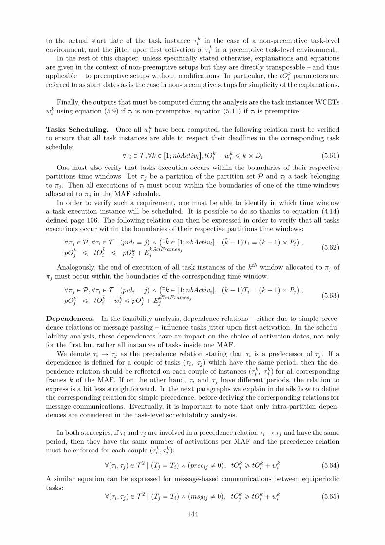
to the actual start date of the task instance τki in the case of a non-preemptive task-levelenvironment, and the jitter upon first activation of τki in a preemptive task-level environment.
In the rest of this chapter, unless specifically stated otherwise, explanations and equationsare given in the context of non-preemptive setups but they are directly transposable – and thusapplicable – to preemptive setups without modifications. In particular, the tOki parameters arereferred to as start dates as is the case in non-preemptive setups for simplicity of the explanations.
Finally, the outputs that must be computed during the analysis are the task instances WCETswki using equation (5.9) if τi is non-preemptive, equation (5.11) if τi is preemptive.
Tasks Scheduling. Once all wki have been computed, the following relation must be verifiedto ensure that all task instances are able to respect their deadlines in the corresponding taskschedule:
@τi P T ,@k P r1;nbActivis, tOki ` wki ď k ˆDi (5.61)One must also verify that tasks execution occurs within the boundaries of their respective
partitions time windows. Let πj be a partition of the partition set P and τi a task belongingto πj . Then all executions of τi must occur within the boundaries of one of the time windowsallocated to πj in the MAF schedule.
In order to verify such a requirement, one must be able to identify in which time windowa task execution instance will be scheduled. It is possible to do so thanks to equation (4.14)defined page 106. The following relation can then be expressed in order to verify that all tasksexecutions occur within the boundaries of their respective partitions time windows:
@πj P P,@τi P T | ppidi “ jq ^`
Dk P r1;nbActivis, | pk ´ 1qTi “ pk ´ 1q ˆ Pj˘
,
pOkj ď tOki ď pOkj ` Ek%nFramesjj
(5.62)
Analogously, the end of execution of all task instances of the kth window allocated to πj ofπj must occur within the boundaries of the corresponding time window.
@πj P P,@τi P T | ppidi “ jq ^`
Dk P r1;nbActivis, | pk ´ 1qTi “ pk ´ 1q ˆ Pj˘
,
pOkj ď tOki ` wki ď pOkj ` E
k%nFramesjj
(5.63)
Dependences. In the feasibility analysis, dependence relations – either due to simple prece-dence relations or message passing – influence tasks jitter upon first activation. In the schedu-lability analysis, these dependences have an impact on the choice of activation dates, not onlyfor the first but rather all instances of tasks inside one MAF.
We denote τi Ñ τj as the precedence relation stating that τi is a predecessor of τj . If adependence is defined for a couple of tasks pτi, τjq which have the same period, then the de-pendence relation should be reflected on each couple of instances pτki , τkj q for all correspondingframes k of the MAF. If on the other hand, τi and τj have different periods, the relation toexpress is a bit less straightforward. In the next paragraphs we explain in details how to definethe corresponding relation for simple precedence, before deriving the corresponding relations formessage communications. Eventually, it is important to note that only intra-partition depen-dences are considered in the task-level schedulability analysis.
In both strategies, if τi and τj are involved in a precedence relation τi Ñ τj and have the sameperiod, then they have the same number of activations per MAF and the precedence relationmust be enforced for each couple pτki , τkj q:
@pτi, τjq P T 2 | pTj “ Tiq ^ pprecij ‰ 0q, tOkj ě tOki ` wki (5.64)
A similar equation can be expressed for message-based communications between equiperiodictasks:
@pτi, τjq P T 2 | pTj “ Tiq ^ pmsgij ‰ 0q, tOkj ě tOki ` wki (5.65)
144
If the precedence relation τi Ñ τj involves two tasks having different periods, then thedependence relation between the instances of τj and τi must be expressed for instances occurringin the same frame, i.e. between instances τki and τ lj where the indexes k and l correspond to thesame frame in the MAF schedule. Two situations can occur depending on the two tasks periods.
If τj is slower than τi, i.e. if Tj ą Ti, then τj has less instances scheduled in one MAF thanτi. The precedence relation must be expressed for all instances of τj to make sure each instanceof τj is scheduled after the corresponding instance of τi. To do so, the precedence relation isexpressed as follows:
@τi, τj P T | pprecij “ 1q ^ pTi ă Tjq ,@l P r1;nbActivjs,
@k P r1;nbActivis | pk ´ 1qTi “ pl ´ 1qTj , tOlj ě tOki ` wki
(5.66)
The condition pk ´ 1qTi “ pl ´ 1qTj enables to match the task instance numbers, i.e. targetcouples of instances τki and τ lj corresponding to the same frame in the MAF schedule, by gettingadvantage of the fact that tasks periods are harmonic and therefore even multiples of each other.
If τj is faster than τi, i.e. if Tj ă Ti, then τj has more instances scheduled in one MAF thanτi. In this case, the precedence relation must be expressed for all instances of τi to make sureeach instance of τi is scheduled before the corresponding instance of τj . To do so, the precedencerelation is expressed as follows:
@τi, τj P T | pprecij “ 1q ^ pTi ą Tjq ,@k P r1;nbActivis,
@l P r1;nbActivjs | pk ´ 1qTi “ pl ´ 1qTj , tOlj ě tOki ` wki
(5.67)
Similar relations can be defined for message-based communications. If Tj ą Ti, the followingrelation must be enforced:
@τi, τj P T | pmsgij “ 1q ^ pTi ă Tjq ,@l P r1;nbActivjs,
@k P r1;nbActivis | pk ´ 1qTi “ pl ´ 1qTj , tOlj ě tOki ` wki
(5.68)
If Tj ă Ti, the following relation must be enforced:
@τi, τj P T | pmsgij “ 1q ^ pTi ą Tjq ,@k P r1;nbActivis,
@l P r1;nbActivjs | pk ´ 1qTi “ pl ´ 1qTj , tOlj ě tOki ` wki
(5.69)
Partition-Level Timing Analysis
The partition-level schedulability analysis is performed after a partition schedule has been built.The goal is to verify that the computed partition-level schedule respects all timing requirementsof the corresponding partitions.
The inputs are a software/hardware allocation, and the partition schedule, i.e. activationdates pOki and the partitions CPU time budgets per frame Eki . The output is the result of theverification of the satisfaction of all partitions timing requirements.
Partitions Scheduling. Once each Eki is computed, the partition-level schedulability analysisthen consists in verifying that all time windows are in line with the corresponding partitionperiodicity. It is indeed the case if the following relation is always verified, for each partition πiand each frame k of the MAF schedule, independently of the considered strategy:
@πi P P,@k P r1;nFramesis, pOki ` Eki ď k ˆ Pi (5.70)
145
In the one-to-all integration strategy, an additional verification must be performed. Indeed,as explained in subsection 5.4, a partition start date pOki must not be bigger than the corre-sponding latest start date latestki defined according to task-level information:
@πi P P,@k P r1;nFramesis, pOki ď latestki (5.71)
Dependences. In the one-to-one integration strategy, no additional partition-level verificationof dependences is necessary, since they are all expressed using the task-level matrices, withoutdifferentiating intra-partition dependences from inter-partition dependences.
In the one-to-all integration strategy however, one needs to verify all inter-partition depen-dences since they are not covered by the matrices representing task-level dependences. To do so,similar verification must be performed, replacing task-level matrices prec and msg by partition-level matrices pPrec and ipc respectively. The same differentiation of the situation dependingon partitions periods holds as well.
In the case of equiperiodic partitions, equations (5.72) and (5.73) must be enforced.
@k P r1;nFramess,@πi, πj P P | pPrecij “ 1, pOkj ě pOki ` Ek%nFramesii (5.72)
@k P r1;nFramess,@πi, πj P P | ipcij “ 1, pOkj ě pOki ` Ek%nFramesii (5.73)
If πi must be scheduled before πj and Pj ą Pi, equations (5.74) and (5.75) must be verified.
@πi, πj P P | ppPrecij “ 1q ^ pPi ă Pjq ,@l P r1;nFramesjs,
@k P r1;nFramesis | pk ´ 1qPi “ pl ´ 1qPj , pOlj ě pOki ` Ek%nFramesii
(5.74)
@πi, πj P P | pipcij “ 1q ^ pPi ă Pjq ,@l P r1;nFramesjs,
@k P r1;nFramesis | pk ´ 1qPi “ pl ´ 1qPj , pOlj ě pOki ` Ek%nFramesii
(5.75)
Finally, if πi must be scheduled before πj and Pj ă Pi, equations (5.76) and (5.77) must beverified.
@πi, πj P P | ppPrecij “ 1q ^ pPi ą Pjq ,@k P r1;nFramesis,
@l P r1;nFramesjs | pk ´ 1qPi “ pl ´ 1qPj , pOlj ě pOki ` Ek%nFramesii
(5.76)
@πi, πj P P | pipcij “ 1q ^ pPi ą Pjq ,@k P r1;nFramesis,
@l P r1;nFramesjs | pk ´ 1qPi “ pl ´ 1qPj , pOlj ě pOki ` Ek%nFramesii
(5.77)
5.6 Discussions
Partitions CPU Time Budgets: Computed during the Allocation Search, Exploitedfor the Schedule Generation. Section 5.3 presents the equations exploited to compute eachpartition CPU time budget per frame Eki in the two integration strategies respectively. They arecomputed using tasks WCETs wi exploited in the allocation problem, no equivalent definitionupdating the Eki parameters in the schedule generation problem is proposed. The reason behindsuch a choice depends on the considered strategy. In the one-to-one integration strategy, the Ekiparameters are computed for verification purposes only, every decision being based on the tasklevel in that strategy.
In the one-to-all strategy, the Eki parameters are exploited for verification, allocation andschedule generation purposes, which means they must already be computed before the schedule
146
generation problem. Indeed, the Eki parameters are inputs of the schedule generation problem,which justifies their computation in the allocation problem, addressed before the schedule prob-lem. One could recompute the Eki parameters during scheduling in order to use task instancesWCETs wki instead of one task WCET for all instances wi, which would be likely to tighten theCPU budgets bounds. However, doing so appears to be useless in the one-to-all strategy exceptfor optimization purposes in order to recompute a new schedule. Even so, all wki may changeonce a new schedule has been defined, and partitions budgets will have to be recomputed aswell.
Boolean Matrices versus Integer Vectors. As already observed in the ”Discussions” sec-tion of chapter 4, it is more beneficial for each CP problem solving to define boolean matricesover vectors of integers for some parameters of our model.
An illustration of such a statement can be identified in the construction of the memoryinterference function dRAM (see section 5.2), in particular with the usage of matrix shared. Themodel needs to identify which cores share some memory areas and which do not, depending onthe core and path allocation. It is easy to do so with a boolean matrix, where, as currentlydefined, the corresponding sharedpq term is either equal to one if cores p and q share somememory area, and zero if they do not.
It is therefore easy to transpose such information into the equations requiring such distinc-tion, by adding the terms sharedpq and p1´ sharedpqq in front of all parts of the equations thatare respectively applicable only to cores sharing and not sharing memory areas. If shared werereplaced with a vector of integers, one would have needed to express equations with conditionson the corresponding integers. However, it would have not been possible to define such equationsin a CP in Cplex [6], which do not allow test conditions to rely on variables of the expressedCP; one would then have had to find some alternative, probably leading to more equationsand/or more intermediary variables to be defined in the CP, therefore uselessly increasing thecomplexity of the corresponding CP.
Path Identification and Memory Interference. The fact that equations have been up-dated with isSharingMC leads to the production of tighter bounds. Without such update, thebounds are perfectly valid, but contains some pessimism. Indeed, cores can share paths withoutsharing memory space, and they are thus likely to interfere at runtime. On the other hand,cores that do not share path to the memory or memory space will never try to access the samememory path, and as such, no memory interference as defined in this thesis: in equations (5.13)and (5.17) which are not updated with path sharing identification, such cores as still taken intoaccount in the computation of RDinter, and consequently, in the computation of the DRAMinterference of tasks that will never be interfering together. This adds a positive integer to thecomputed WCET bound corresponding to unnecessary pessimism.
5.7 Summary
In this chapter, we presented how we constructed the timing analysis metrics necessary duringsoftware/hardware integration. To our knowledge, the proposed metrics are the first to beadapted for multicore since they are interference-aware, but also to IMA since specific care forthe partition level has been taken.
The first timing analysis is a sufficient condition for feasibility of a multicore based IMAsystem, and is exploited when guiding the software/hardware allocation exploration search. Thesecond timing analysis metric is a schedulability analysis to verify that all timing requirementsof the systems are enforced in a given schedule. It is used once the allocation has been done,when computing activation dates to build a static schedule for one MAF of the system.
This chapter presented each analysis metric. In particular, the chapter includes an extendeddescription of the interference computational models we implemented to bound inter-task inter-
147
ference. The equations corresponding to the timing verification to be performed when analysingthe timing properties of a systems are also given in this chapter, but not yet positioned withregards to the industrial system design process, which will rather be done in the next chapter.
148
Chapter 6
IMA System Integration
This chapter presents the integration strategies proposed in this thesis.For each strategy, we first give a general overview in chronological order of the activities
constituting the proposed integration process. We then describe each step in greater details.In order to help automate the activities involved in each integration strategies, we propose tocover every step separately using constraint programming (CP). The resulting CP formulationdefined for each step will be presented in a dedicated subsection describing the correspondingstep.
6.1 One-to-All Integration Strategy
Strategy Overview
This section describes in detail the one-to-all integration strategy proposed in this thesis. Asillustrated in figure 6.1, this strategy is divided into three steps. We describe them in chrono-logical order and specify which role is in charge of which activities and during which step of theintegration process.
The one-to-all integration strategy consists in the following steps, also summarized in figure6.1:
• Step AS1 - SW/HW allocation: This step is performed by each application supplier,alone on its own applications.During step AS1, each application supplier must decide, for each partition separately, onwhich core to allocate the tasks of its partitions. Each supplier must do so while ensuringthe selected allocation is safe, for instance by verifying that no task will overrun its deadlineat runtime despite interference.To automate this allocation activity and ease the timing analysis to be performed to ensurethe validity of the chosen allocation, we propose a CP formulation, named AS11cp. ThisCP will be presented in details later in the subsection detailing the content of step AS1.The result of step AS1 is a task-to-core allocation, for all partition designed by the corre-sponding application supplier.
• Step MI1 - Global allocation verification and partition-level schedule genera-tion: This step is performed by the module integrator, who receives feedback from eachsupplier on the allocations chosen during step AS1.During step MI1, the module integrator is in charge of verifying the global allocation, i.e.verifying the existence of a feasible schedule with all partitions according to informationon each partition provided separately by each supplier. If the verification results in thenegation of existence of a valid schedule, the integrator discusses with some or all suppliersin order to negotiate some changes to the configuration choices made in step AS1. If on the
149
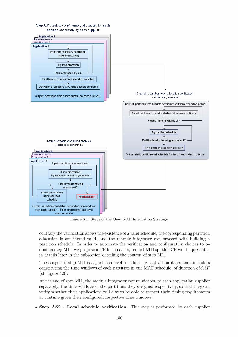
Figure 6.1: Steps of the One-to-All Integration Strategy
contrary the verification shows the existence of a valid schedule, the corresponding partitionallocation is considered valid, and the module integrator can proceed with building apartition schedule. In order to automate the verification and configuration choices to bedone in step MI1, we propose a CP formulation, named MI1cp; this CP will be presentedin details later in the subsection detailing the content of step MI1.
The output of step MI1 is a partition-level schedule, i.e. activation dates and time slotsconstituting the time windows of each partition in one MAF schedule, of duration gMAF(cf. figure 4.6).
At the end of step MI1, the module integrator communicates, to each application supplierseparately, the time windows of the partitions they designed respectively, so that they canverify whether their applications will always be able to respect their timing requirementsat runtime given their configured, respective time windows.
• Step AS2 - Local schedule verification: This step is performed by each supplier
150

separately, on their own partitions.During step AS2, each supplier is in charge of verifying the behavior of their partitionsat runtime by checking whether the tasks inside each partition will always be able torespect their timing requirements, given that they must be scheduled within the boundariesof their respective partitions time windows. If the verification fails for some partitions,the corresponding suppliers communicate with the integrator in order to negotiate somechanges to the partition schedule built in step MI1 or the allocation choices made in stepAS1.In order to automate the verification and configuration choices to be done in step AS2,we propose a CP formulation, named AS2cp; this CP will be presented in details later inthe subsection detailing the content of step AS2.
By the end of step AS2, if all partitions schedules respectively lead to the existence of validtask-level schedules, then the integration process ends successfully with a valid partition sched-ule for the corresponding module.
In the rest of this section, we describe in detail each of these steps, and their correspondingCP formulation. Each subsection describes one of the steps of the one-to-all integration strategy,including the content of the corresponding CP proposed.
Step AS1: SW/HW Allocation and Verification
This step is performed by each supplier on their own and separately from each other. For everypartition, each application supplier must select a task-to-core allocation, verify that the corre-sponding timing properties satisfy the system requirements, and derive the associated partitionsCPU time budgets per frame. In particular, this implies the computation of tasks WCETs andpartitions CPU time budgets per frame Eki .
We propose to automate step AS1 by expressing them in a CP called AS1cp. The goal ofAS1cp is to find an allocation such that, inside each partition, all tasks are schedulable and alltiming requirements of the partition are guaranteed to always be respected at runtime.
To do so, the inputs of the defined CP are the description of the software and hardwarearchitectures. The outputs of the CP are a software/hardware allocation – represented by naand t2mc along with the partitions CPU time budgets per frame Eki and the tasks WCETswi as outputs. The constraints of the CP correspond to the allocation choices, the allocationverification and the time budgets and WCETs computation (see listing of constraints for theallocation problem in chapter 4).
To solve AS1cp, the search algorithm exploited by the CP solver explores the possibilitiesof allocation combinations, and for each combination evaluated, check whether all expressedconstraints are satisfied. If such a combination exists, it is considered to be a solution of theallocation problem, and will be stored temporarily by the solver until one of such solutions isfinally selected at the end of the solving process of AS1cp. If no such combination exists, itmeans it is not possible to allocate the software platform onto the hardware platform whileguaranteeing the existence of a safe schedule for the corresponding system according to thetiming analysis presented in chapter 5. Some modification must then be undertaken on thesoftware and/or the hardware platform until AS1cp is able to find a solution. For instance,this may involve deciding to decrease or increase the number of cores to be used, or deciding tointegrate less partitions onto the same module.
We present here the CP formulation of the allocation problem proposed in this thesis, referredto as AS1cp.
Inputs of AS1cp The inputs to AS1cp are, relatively to each application supplier: the entirehardware model (see subsection ”Hardware Architecture in chapter 4), the partitions periods
151
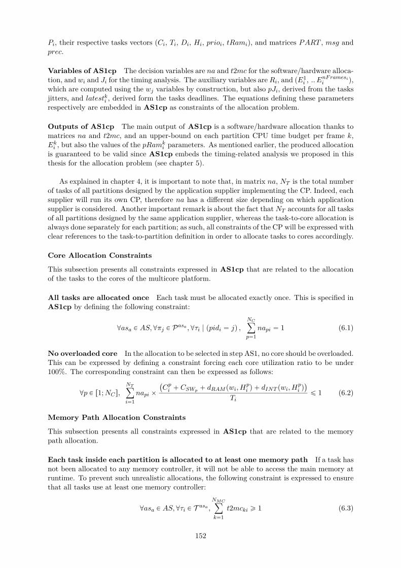
Pi, their respective tasks vectors (Ci, Ti, Di, Hi, prioi, tRami), and matrices PART , msg andprec.
Variables of AS1cp The decision variables are na and t2mc for the software/hardware alloca-tion, and wi and Ji for the timing analysis. The auxiliary variables are Ri, and pE1
i , .. EnFramesii q,
which are computed using the wj variables by construction, but also pJi, derived from the tasksjitters, and latestki , derived form the tasks deadlines. The equations defining these parametersrespectively are embedded in AS1cp as constraints of the allocation problem.
Outputs of AS1cp The main output of AS1cp is a software/hardware allocation thanks tomatrices na and t2mc, and an upper-bound on each partition CPU time budget per frame k,Eki , but also the values of the pRamk
i parameters. As mentioned earlier, the produced allocationis guaranteed to be valid since AS1cp embeds the timing-related analysis we proposed in thisthesis for the allocation problem (see chapter 5).
As explained in chapter 4, it is important to note that, in matrix na, NT is the total numberof tasks of all partitions designed by the application supplier implementing the CP. Indeed, eachsupplier will run its own CP, therefore na has a different size depending on which applicationsupplier is considered. Another important remark is about the fact that NT accounts for all tasksof all partitions designed by the same application supplier, whereas the task-to-core allocation isalways done separately for each partition; as such, all constraints of the CP will be expressed withclear references to the task-to-partition definition in order to allocate tasks to cores accordingly.
Core Allocation Constraints
This subsection presents all constraints expressed in AS1cp that are related to the allocationof the tasks to the cores of the multicore platform.
All tasks are allocated once Each task must be allocated exactly once. This is specified inAS1cp by defining the following constraint:
@asa P AS,@πj P Pasa ,@τi | ppidi “ jq ,NCÿ
p“1napi “ 1 (6.1)
No overloaded core In the allocation to be selected in step AS1, no core should be overloaded.This can be expressed by defining a constraint forcing each core utilization ratio to be under100%. The corresponding constraint can then be expressed as follows:
@p P r1;NCs,NTÿ
i“1napi ˆ
`
Cpi ` CSWp ` dRAM pwi, Hpi q ` dINT pwi, H
pi q˘
Tiď 1 (6.2)
Memory Path Allocation Constraints
This subsection presents all constraints expressed in AS1cp that are related to the memorypath allocation.
Each task inside each partition is allocated to at least one memory path If a task hasnot been allocated to any memory controller, it will not be able to access the main memory atruntime. To prevent such unrealistic allocations, the following constraint is expressed to ensurethat all tasks use at least one memory controller:
@asa P AS,@τi P T asa ,NMCÿ
k“1t2mcki ě 1 (6.3)
152
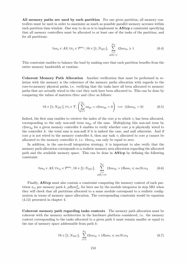
All memory paths are used by each partition For one given partition, all memory con-trollers must be used in order to maximize as much as possible parallel memory accesses withineach partition time window. One way to do so is to implement in AS1cp a constraint specifyingthat all memory controllers must be allocated to at least one of the tasks of the partition, andfor all partitions:
@asa P AS,@πj P Pasa ,@k P r1;NMCs,NTÿ
i“1pidi“j
t2mcki ě 1 (6.4)
This constraint enables to balance the load by making sure that each partition benefits from theentire memory bandwidth at runtime.
Coherent Memory Path Allocation Another verification that must be performed in re-lation with the memory is the coherence of the memory paths allocation with regards to thecore-to-memory physical paths, i.e. verifying that the tasks have all been allocated to memorypaths that are actually wired to the core they each have been allocated to. This can be done bycomparing the values of matrices t2mc and c2mc as follows:
@k P r1;NMCs,@τi P T ,
˜
NCÿ
p“1napi ˆ c2mckp “ 0
¸
ùñ pt2mcki “ 0q (6.5)
Indeed, the first sum enables to retrieve the index of the core p to which τi has been allocated,corresponding to the only non-null term napi of the sum. Multiplying this non-nul term byc2mckp for a given memory controller k enables to verify whether core p is physically wired tothe controller k: the total sum is non-null if it is indeed the case, and null otherwise. And ifcore p is not wired to the memory controller k, then any task τi allocated to core p cannot beallocated to the memory controller k, i.e. t2mcki can only be equal to zero.
In addition, in the one-to-all integration strategy, it is important to also verify that thememory path allocation corresponds to a realistic memory area allocation regarding the allocatedpath and the available memory space. This can be done in AS1cp by defining the followingconstraint:
@asa P AS,@πm P Pasa ,@k P r1;NMCs,NTÿ
i“1pidi“m
t2mcki ˆ tRami ď mcSizek (6.6)
Finally, AS1cp must also contain a constraint computing the memory context of each par-tition πm per memory path k, pRamk
m, for later use by the module integrator in step MI1 whenthey will check that all partitions allocated to a same module correspond to a realistic config-uration in terms of memory space allocation. The corresponding constraint would be equation(4.12) presented in chapter 4.
Coherent memory path regarding tasks contexts The memory path allocation must becoherent with the memory architecture in the hardware platform considered, i.e. the memorycontext corresponding to the tasks allocated to a given path k must remain smaller or equal tothe size of memory space addressable from path k:
@k P r1;NMCs,NTÿ
i“1t2mcki ˆ tRami ď mcSizek (6.7)
153
Coherent memory path allocation regarding Message-Based Communications Iftwo tasks are involved in some message passing scenario, then they both must be able to accessthe corresponding shared memory area. As explained before, we assume the corresponding areato be stored in a memory area that is accessible by producer and consumer tasks. As such, theconstraint to be expressed must specify that the producer task must be able to access the samememory area than the consumer task. This corresponds to the following constraint:
@asa P AS,@τi, τj P T asa , pmsgji `msgijq ‰ 0 ùñ
ˆ
NMCř
k“1t2mcki ˆ t2mckj ě 1
˙
(6.8)
Indeed, if two tasks τi and τj exchange messages at runtime, they must have at least one memorypath in common in order to be able to access the shared memory where the correspondingmessage will be stored. In this equation, the term pmsgji `msgijq enables to select couples oftasks pτi, τjq that are involved in message-based communications. For such couples, the tasksmust have at least one memory path in common, i.e. there exists at least one memory pathindex k for which the term t2mcki ˆ t2mckj is not null.
Schedulability Constraints
This subsection presents all constraints expressed in AS1cp that are related to the verification oftiming-related properties of the evaluated allocations. Altogether, these constraints represent thefeasibility analysis proposed in this thesis for early timing analysis and for guiding the allocationsearch in a safe manner by forcing the choice of allocation to correspond to an allocation thatpasses the feasibility test.
Partitions Time Budgets per Frame Eki Computation The feasibility analysis includesverifying that each partition time budget per frame can be provided within the period of thecorresponding partition. This includes computing the partition time budgets per frame Eki first.To do so, equation (5.47) (see chapter 5) is embedded as a constraint in AS1cp.
Link between task-level and partition-level requirements: latest possible activationof partition window When configuring the SW/HW allocation, each supplier must verifythat no frame is overloaded, i.e. that the CPU time budget required by every partition πi everyPi time units actually fits a time interval of length Pi. If such a relation is not verified, it meansthat the corresponding partition periodicity is too fast for all its tasks to start and completetheir executions normally.
Partitions periods are chosen with the knowledge of their tasks execution needs, but forsingle-core environments. Indeed, the occurrence of multicore interference suffered by tasks atruntime may be so important that a partition tasks would require a time window that actually isbigger than the partition period in order for all of them to complete their respective executions.AS1cp must be able to detect such situations in order to not select a SW/HW allocation leadingto such a situation for any partition. Detecting such situations by exploiting AS1cp assists thecorresponding supplier: if no valid allocation exists for a given partition because of a periodicitythat is too fast, the supplier may want to increase the value of the period.
Partitions time budgets Eki have been computed using task-level information: indeed, asexplained in the previous paragraph, they rely on tasks WCRTs, which include upper-boundson multicore interference. In order to check whether it will be possible to find a partition-levelschedule that matches tasks requirements, one must also be able to extract knowledge abouttasks jitters and precedence relations which are constraining their possible activation dates. Todo so, pJi and latestki have been defined for each partition πi. They are computed using equations(5.54) and (5.55) respectively, which must therefore be expressed in AS1cp as constraints.
In addition, equation (5.56) is embedded in AS1cp as a constraint as well in order to verifythat latestki matches its definition domain.
154
All partitions are schedulable As explained in details in chapter 5, equations (5.57) and(5.58) may be used in order to check whether there exists partitions time windows fitting theirrespective definition domain, i.e. that the kth window of πi can be scheduled within the bound-aries of the kth frame of the partition cycle.
All tasks are schedulable As mentioned at the beginning of the subsection, AS1cp embracesthe task-level timing related verification proposed in chapter 5, which takes the form of a systemof equation to be solved and an equation to be verified by all tasks in order to pass the test.As such: (5.7) is expressed as a constraint of AS11cp to compute tasks wi and Ji. Equation(5.51) is expressed as well in order to verify feasibility of τi. Equations (5.48), (5.49) and (5.50)are embedded in AS11cp in order to compute tasks jitters upon first activation accordingly.
Finally, AS1cp must contain the verification that all tasks are able to complete every exe-cution before their respective deadline. This is usually expressed using the following equation:
@asa P AS,@πi P Pasa ,@τj P T asa | ppidj “ iq , Jj ` wj ď Dj (6.9)
However, equation (6.9) does not take into account a hierarchically constrained environmentsuch as the partition level in IMA systems. In fact, just as a task τj may have some jitter uponfirst activation Jj that is non-null, its partition πi may have one as well, pJi. The partitionwindow defining the valid interval in which a task can be executed, partitions jitters must betaken into account when verifying the feasibility of tasks in IMA systems. As such, equation(6.9) will rather be replaced by the following equation in AS1cp:
@asa P AS,@πi P Pasa ,@τj P T asa | ppidj “ iq , max ppJi, Jjq ` wj ď Dj (6.10)
where max ppJi, Jjq enables to take into account both the task and its partition jitter.
Message passing and precedence relations As briefly mentioned in chapter 4, tasks jitterupon first activation Ji are computed according to the precedence and message relations betweentasks as specified in the software architecture. If a task does not have any predecessor or doesnot receive any message at runtime, its jitter is null. Based on equation (5.48) expressed page140, this relation is represented in AS1cp as follows:
@τi P T ,
¨
˚
˝
NTÿ
k“1k‰i
pmsgki ` preckiq “ 0
˛
‹
‚
ùñ pJi “ 0q (6.11)
On the contrary, if a task has predecessors or receives messages, its jitter upon activationmust correspond to the end of execution of all its predecessors and/or message senders. Basedon equation (5.49) expressed page 140, in order to cover such situations, the following constraintmust be specified in AS1cp:
@τi P T ,
¨
˚
˝
NTÿ
k“1k‰i
pmsgki ` preckiq ‰ 0
˛
‹
‚
ùñ
¨
˝Ji ě maxτkPT
msgki`precki‰0
pJk ` wkq
˛
‚ (6.12)
Affinities and exclusion constraints The task-to-core allocation must be in line with thetask-to-core affinities expressed by the application supplier. In fact, the following relation mustbe verified if two tasks that must be allocated to the same core according to taskCoreAff:
@asa P AS,@τi P T asa ,@p P r1;NCs,`
taskCoreAffpi ě 1˘
ùñ pnapi “ 1q (6.13)
Similarly, the task-to-task affinities must be respected in the task-to-core allocation:
@asa P AS,@τi, τj P T asa ,`
taskAffij “ 1˘
ùñ
˜
NCÿ
p“1napi ˆ napj “ 1
¸
(6.14)
155

Finally, the task-to-task exclusions expressed by the application supplier must be reflectedin the selected task-to-core allocation:
@asa P AS,@τi, τj P T asa , ptaskExij “ 1q ùñ˜
NCÿ
p“1napi ˆ napj “ 0
¸
(6.15)
Objective Function
More than one valid solution to the problem expressed in AS1cp may exist. As such, we defineadditional objective functions to help classify the valid solutions into ”optimized solutions” and”less optimized solutions”, according to optimization parameters such as workload reduction forinstance. The optimization criteria is defined according to preferences of the system designers.
For instance, one preferred optimization criteria for the module integrator is the reduction ofEki budgets, as mentioned before. The corresponding objective function would be the following:
Minimize maxπiPP
˜
nFramesiÿ
k“1Eki
¸
(6.16)
Where NP stands for the total number of partitions defined by each application supplier.
Another optimization criteria that may suit system designers targets the workload reductionper core. According to the definition that can be found in the literature, the objective functionminimizing the CPU workload for each core would be the following:
MinimizeNCÿ
p“1napj ˆ
CpjTj
(6.17)
However, although Cpj is usually used to define tasks workloads, the values of the Cpj pa-rameters are constant integers in our model. Such an objective function is therefore of no useto the workload reduction. An alternative to the Cpj parameters to model the contribution ofτj to the CPU workload would be to define the workload depending on the tasks interferencedelays, which participation to the workload can often be far from negligible at runtime. Tofavor solutions in which interference are reduced, we therefore define the workload according tointerference by implementing the following objective function:
MinimizeNCÿ
p“1napj ˆ
Cpj ` dRAM pwi, Hpi q ` dINT pwi, H
pi q
Tj(6.18)
where the general term of the sum enforces the minimization of the workload of each core p.The total sum therefore ensures that each CPU workload is minimized as much as possible bythe CP solving process, as a sum of positive terms to be minimized.
According to equation (6.18), workload reduction actually relies on multicore interferencereduction. Multicore interference being the variable part of a task WCET, and by construction,of a partition CPU time budget, this also means objective function defined via equation (6.18)addresses the objective expressed by equation (6.16) as well.
However, by construction of schedules in the one-to-all integration strategy (see figure 4.6),the actual parameter constraining the usage of each core is the partitions CPU time budgetsrather than the tasks WCETs. WCETs can be reduced as much as possible, but the correspond-ing tasks poorly scheduled, which would lead to minimized inter-task interference, and at thesame time, large partitions CPU time budgets, and therefore lead to lower integration ratio andthus under-optimized designs.
On the contrary, the objective of reducing as much as possible partitions CPU time budgetsactually leads to reducing as much as possible tasks WCETs. Consequently, equation (6.16)may be the most appropriate objective function to be implemented in step AS1.
156
Step MI1: Global Allocation Verification and Partition-Level Schedule Gen-eration
Step MI1 is performed by the module integrator, after step AS1 has been completed by everyapplication supplier. The output of AS1 is a task-to-core allocation and the correspondingpartitions CPU time budgets per frame. These outputs are provided by each supplier to theintegrator, along with the corresponding partitions periods Pi and memory budgets per pathpRamk
i . Once the module integrator has all partitions time and memory budgets, they cancompute the value of the MAF gMAF and verify that the overall allocation is valid. If it is notthe case, the integrator discusses with some or all the suppliers in order to negotiate changesto the configurations set in step AS1. If it is the case, the integrator proceeds with building apartition-level schedule of a duration of one MAF.
As illustrated in figure 4.7, to compute a schedule, the module integrator must decomposeone MAF into time slots for each partition, according to their time budgets Ekm.
k ” k1 mod nFramesm (6.19)
To automate the activities performed in step MI1, we propose a CP formulation namedMI1cp, in order to generate partitions activation dates pOki for one MAF where all timingrequirements of the systems are respected.
Inputs of MI1cp As explained before, step MI1 takes as input the outputs of step AS1,performed by each supplier on all applications to be integrated on the same multicore module.Moreover, step MI1 is performed by the module integrator. As such, the main inputs to MI1cpare partition-level information such as pRamk
i , Eki and latestki Pi parameters.
Variables of MI1cp The variables of MI1cp are the partitions windows start dates pOki , andthe total number of windows implemented per partition πi in the MAF schedule, nbWindowsi.
Outputs of MI1cp The main output of MI1cp is a partition schedule that has been verifiedat partition-level. As such, the outputs of MI1cp are the partitions windows activation datespOki , the total number of windows per partition nbWindowsi, but also the MAF gMAF andMIF gMIF on the system.
Finally, at the end of step MI1, the module integrator communicates, to each supplier sepa-rately, the time windows of their respective partitions so that each of them can perform furtherverifications on their own applications at task-level in step AS2.
Preprocessing and Integrated allocation verification
preprocessing phase of MI1 In step MI1, the module integrator receives – as inputs fromeach supplier – the Eki parameters of each partition in their respective cycle frames. Then, themodule integrator computes the MIF and MAF of the corresponding system according to thepartitions periods. This gives the total number of frames in one MAF, nFrames.
As illustrated in figure 4.7 page 105, the number of frames nFrames in one MAF may bedifferent from the number of frames in each partition cycle nFramesi. One consequence is thatthe number of CPU time budget per frame Eki computed for each partition πi is computed withk P r1;nFramesis. In step MI1, the module integrator defines partition windows for each framek P r1;nFramess, knowing that nFrames is an even multiple of nFramesi and that partitionsperiods Pi are harmonic. Let Eki be the CPU time budget computed by the application supplierasa responsible of the design of πi, with k P r1;nFramesis. The first step prior to defining andlaunching the CP search corresponding to step MI1 is to derive the CPU time budgets per framefor each partition πi for the duration of one complete MAF; let Eki denote such a time budget,
157
with k P r1;nFramess. The relation between Eki and Eki is the following:
@asa P AS,@πi P Pasa ,@k, k P r1;nFramesis ˆ r1;nFramess,
Eki “
#
Epk´1q%nFramesi`1i if ppk ´ 1q ˆ gMIF q “ 0 mod pPiq
0 otherwise.(6.20)
Similarly, let ˜latestki denote the parameters computed by the supplier πi with k P r1;nFramesis,
and latestki the corresponding parameters extended to one complete MAF with k P r1;nFramess.The relation between ˜latest
ki and latestki is the following:
@asa P AS,@πi P Pasa ,@k, k P r1;nFramesis ˆ r1;nFramess,
latestki “
#
˜latestpk´1q%nFramesi`1i if ppk ´ 1q ˆ gMIF q “ 0 mod pPiq
0 otherwise.(6.21)
At the beginning of step MI1, all computations involving any of the Eki and latestki parame-ters are performed on one MAF, i.e. with k P r1;nFramess. As such, the computations inducedby equations (6.20) and (6.21) are done prior to all activities done in step MI1 and described inthis subsection.
Memory Allocation Verification Another verification that must be done prior to generatinga schedule, is the coherence of the memory allocation. In fact, the module integrator has tocheck that the memory allocation is realistic: it is the case if, when combining all partitionsof a same module, the total memory footprint of partitions on a same core is smaller than orequal to the size of memory addressed by the corresponding core. More precisely, the size ofmemory addressed by each core according to the selected task-to-memory allocation is not biggerthan the physically addressable memory area for each core. Such a property corresponds to thefollowing relation:
@k P r1;NMCs,NPÿ
i“1pRamk
i ď mcSizek (6.22)
Where pRamki is computed using equation (4.12). However, the module integrator is not allowed
ot perform any task-level verification. As an alternative, the module integrator must work withthe partitions memory budgets per path pRamk
i , computed as outputs of AS1cp.The following constraint must then be expressed in MI1cp to verify that the memory path
allocation is realistic in terms of memory layout:
@k P r1;NMCs,NPÿ
i“1pRamk
i ď mcSizek (6.23)
Schedule Generation Constraints
Partition Windows Start Dates In step MI1, the module integrator generates a partition-level schedule by setting the start date pOki of each partition window. It is done automaticallyin MI1cp by defining pOki as variables of the problem. To do so, a constraint must be expressedin MI1cp in order to check that pOki is defined correctly. In fact, it is important to keep inmind the fact that although there are nFramesi CPU time budgets defined for πi, there arenFrames windows and start dates to be defined for πi in one MAF. The index k of each variablepOki is defined in the interval r1;nFramess. Moreover, the MIF is always smaller than or equalto Pi for each partition. As such, if gMIF is smaller than Pi for a given partition πi, thenthere are more pOki variables than there actually are windows for πi in one MAF. As such inMI1cp, there should be a constraint setting to zero all pOki variables for all indexes k that do
158
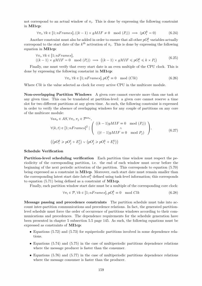
not correspond to an actual window of πi. This is done by expressing the following constraintin MI1cp:
@πi,@k P r1;nFramess, ppk ´ 1q ˆ gMIF ‰ 0 mod pPiqq ùñ ppOki “ 0q (6.24)
Another constraint must also be added in order to ensure that all other pOki variables actuallycorrespond to the start date of the kth activation of πi. This is done by expressing the followingequation in MI1cp:
@πi,@k P r1;nFramess,ppk ´ 1q ˆ gMIF “ 0 mod pPiqq ùñ
`
pk ´ 1q ˆ gMIF ď pOki ď k ˆ Pi˘ (6.25)
Finally, one must verify that every start date is an even multiple of the CPU clock. This isdone by expressing the following constarint in MI1cp:
@πi,@k P r1;nFramess, pOki ” 0 mod pClkq (6.26)
Where Clk is the value selected as clock for every active CPU in the multicore module.
Non-overlapping Partition Windows A given core cannot execute more than one task atany given time. This can be translated at partition-level: a given core cannot reserve a timeslot for two different partitions at any given time. As such, the following constraint is expressedin order to verify the absence of overlapping windows for any couple of partitions on any coreof the multicore module:
@asa P AS,@πi, πj P Pasa ,
@pk, tq P r1;nFramess2 |
¨
˝
ppk ´ 1qgMIF ” 0 mod pPiqq^
ppt´ 1qgMIF ” 0 mod Pjq
˛
‚,
``
pOki ě pOtj ` Etj
˘
_`
pOtj ě pOki ` Eki
˘˘
(6.27)
Schedule Verification
Partition-level scheduling verification Each partition time window must respect the pe-riodicity of the corresponding partition, i.e. the end of each window must occur before thebeginning of the next periodic activation of the partition. This corresponds to equation (5.70)being expressed as a constraint in MI1cp. Moreover, each start date must remain smaller thanthe corresponding latest start date latestki defined using task-level information; this correspondsto equation (5.71) being defined as a constraint of MI1cp.
Finally, each partition window start date must be a multiple of the corresponding core clock:
@πi P P,@k P r1;nFramess, pOki ” 0 mod Clk (6.28)
Message passing and precedence constraints The partition schedule must take into ac-count inter-partition communications and precedence relations. In fact, the generated partition-level schedule must force the order of occurrence of partitions windows according to their com-munications and precedences. The dependence requirements for the schedule generation havebeen presented in chapter 5 subsection 5.5 page 145. As such, the following equations must beexpressed as constraints of MI1cp:
• Equations (5.72) and (5.73) for equiperiodic partitions involved in some dependence rela-tions.
• Equations (5.74) and (5.75) in the case of multiperiodic partitions dependence relationswhere the message producer is faster than the consumer.
• Equations (5.76) and (5.77) in the case of multiperiodic partitions dependence relationswhere the message consumer is faster than the producer.
159
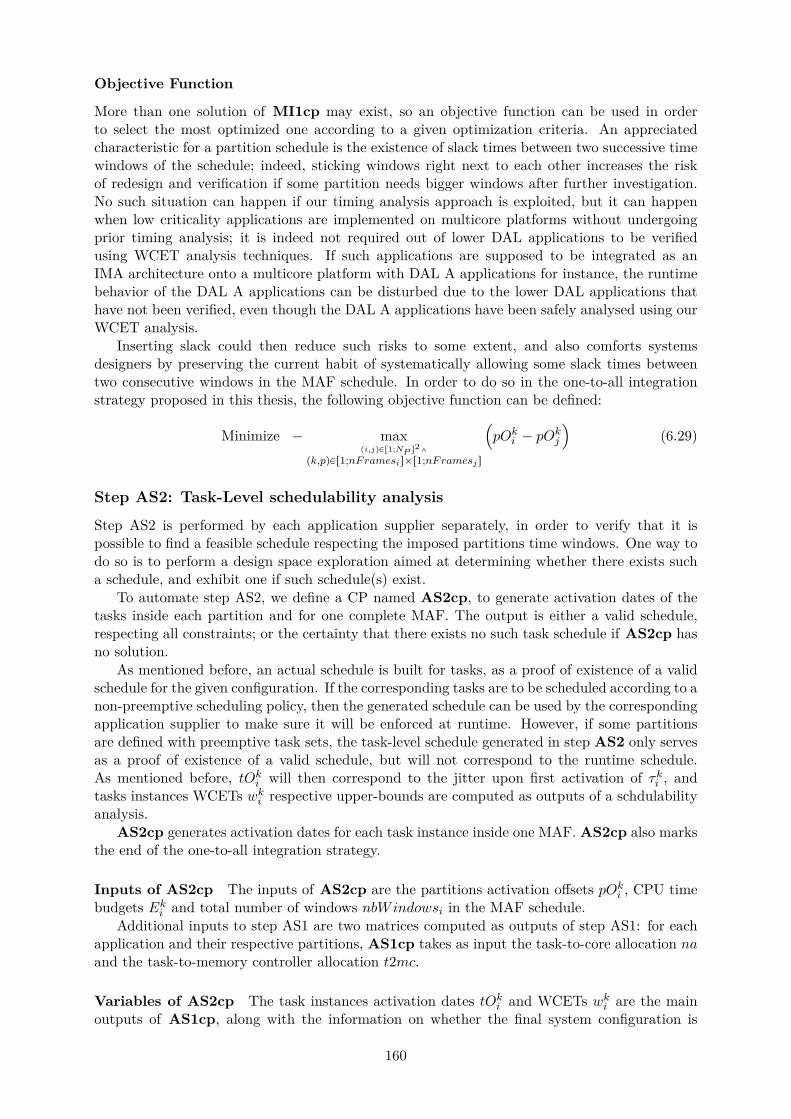
Objective Function
More than one solution of MI1cp may exist, so an objective function can be used in orderto select the most optimized one according to a given optimization criteria. An appreciatedcharacteristic for a partition schedule is the existence of slack times between two successive timewindows of the schedule; indeed, sticking windows right next to each other increases the riskof redesign and verification if some partition needs bigger windows after further investigation.No such situation can happen if our timing analysis approach is exploited, but it can happenwhen low criticality applications are implemented on multicore platforms without undergoingprior timing analysis; it is indeed not required out of lower DAL applications to be verifiedusing WCET analysis techniques. If such applications are supposed to be integrated as anIMA architecture onto a multicore platform with DAL A applications for instance, the runtimebehavior of the DAL A applications can be disturbed due to the lower DAL applications thathave not been verified, even though the DAL A applications have been safely analysed using ourWCET analysis.
Inserting slack could then reduce such risks to some extent, and also comforts systemsdesigners by preserving the current habit of systematically allowing some slack times betweentwo consecutive windows in the MAF schedule. In order to do so in the one-to-all integrationstrategy proposed in this thesis, the following objective function can be defined:
Minimize ´ maxpi,jqPr1;NP s2^
pk,pqPr1;nFramesisˆr1;nFramesjs
´
pOki ´ pOkj
¯
(6.29)
Step AS2: Task-Level schedulability analysis
Step AS2 is performed by each application supplier separately, in order to verify that it ispossible to find a feasible schedule respecting the imposed partitions time windows. One way todo so is to perform a design space exploration aimed at determining whether there exists sucha schedule, and exhibit one if such schedule(s) exist.
To automate step AS2, we define a CP named AS2cp, to generate activation dates of thetasks inside each partition and for one complete MAF. The output is either a valid schedule,respecting all constraints; or the certainty that there exists no such task schedule if AS2cp hasno solution.
As mentioned before, an actual schedule is built for tasks, as a proof of existence of a validschedule for the given configuration. If the corresponding tasks are to be scheduled according to anon-preemptive scheduling policy, then the generated schedule can be used by the correspondingapplication supplier to make sure it will be enforced at runtime. However, if some partitionsare defined with preemptive task sets, the task-level schedule generated in step AS2 only servesas a proof of existence of a valid schedule, but will not correspond to the runtime schedule.As mentioned before, tOki will then correspond to the jitter upon first activation of τki , andtasks instances WCETs wki respective upper-bounds are computed as outputs of a schdulabilityanalysis.
AS2cp generates activation dates for each task instance inside one MAF. AS2cp also marksthe end of the one-to-all integration strategy.
Inputs of AS2cp The inputs of AS2cp are the partitions activation offsets pOki , CPU timebudgets Eki and total number of windows nbWindowsi in the MAF schedule.
Additional inputs to step AS1 are two matrices computed as outputs of step AS1: for eachapplication and their respective partitions, AS1cp takes as input the task-to-core allocation naand the task-to-memory controller allocation t2mc.
Variables of AS2cp The task instances activation dates tOki and WCETs wki are the mainoutputs of AS1cp, along with the information on whether the final system configuration is
160

schedulable at task-level for all partitions. If it is not the case, AS2cp will detect that theexpressed problem has no solution. If it is the case, AS2cp will exhibit a solution that respectsall scheduling constraints expressed in the next paragraphs.
Outputs of AS2cp The output of AS2cp is a task-level schedule for the correspondingpartitions when there exists at least one such schedule. If it is not the case, then it means thetiming analyses proposed in this thesis and embedded in AS2cp were not able to find a task-level schedule for the given partition-level schedule built by the module integrator in step MI1for the corresponding partitions. If a partition falls into such a situation, the module integratormust propose a new partition-level schedule to the corresponding application supplier or proposesome configuration modifications. The outputs of AS2cp are the task instances activation datestOki and WCETs wki .
Schedule Generation Constraints
Activation dates definition A task may have a different period than its partition. As such,it is not scheduled in each time window of its partition in a given MAF. However, similarlyto partitions windows start dates, nFrames start dates tOki are defined for each task τi, all ofwhich not corresponding to an actual execution of τi. For all index k such that tOki does notcorrespond to the actual kth execution of τi must be set to zero in AS2cp:
@asa P AS,@πi P Pasa ,@k P r1;nFramess,@τj P T asa | pidj “ i,ppk ´ 1q ˆ gMIF ‰ 0 mod Tjq ùñ
`
tOki “ 0˘ (6.30)
Otherwise, all other activation dates must be in the corresponding definition domain:@asa P AS,@πi P Pasa ,@k P r1;nFramess,@τj P T asa | pidj “ i,ppk ´ 1q ˆ gMIF “ 0 mod Tjq ùñ
`
pk ´ 1q ˆ Tj ď tOki ď k ˆ Tj˘ (6.31)
Finally, all start dates must be even multiples of the CPU clock.
@τi P T ,@k P r1;nbActivis, tOki ” 0 mod Clk (6.32)
Partition-level windows enforcement The relation expressed in equation (6.31) is valid forany real-time environment. However in IMA software, a task execution can occur only withinthe boundaries of its partition time windows. As such, equation (6.31) must be reinforced bythe following equation:
@asa P AS,@πi P Pasa ,@k P r1;nFramess,@τj P T asa | pidj “ i,ppk ´ 1q ˆ gMIF “ 0 mod Tjqùñ
`
pOki ď tOkj˘
^`
tOkj ` wkj ď k ˆ pOki ` E
ki
˘
(6.33)
The left member of relation 6.33 selects tasks of a given partition that are activated in the kthwindow of their partitions respectively; the right member then forces the task execution to startand finish within the boundaries of the partition kth window.
Non-overlapping executions If the partition under evaluation implements non preemptivetasks, the output of AS2cp will either be the absence of solution or a static schedule ensuredto be valid. To ensure such validity, one must first ensure that the produced schedule does notimplement overlapping executions of different tasks on the same core. The absence of collisionin the schedule is verified by expressing the following constraint:
@asa P AS,@πm P Pasa | pisPreemptive “ 0q,@τi, τj P T asa | ppidi “ pidjq,@k P r1;nFramess,˜
NCř
p“1napi ˆ napj ‰ 0
¸
^ ppk ´ 1q ˆ gMIF “ 0 mod Tiq
^ ppk ´ 1q ˆ gMIF “ 0 mod Tjqùñ
``
tOkj ě tOki ` wki
˘
_`
tOkj ` wkj ď tOki
˘˘
(6.34)
161

The first relation of the left part of the constraint allows to focus on tasks of a partition πm thatare allocated to two different cores. The other two relations of the left part of the constraintenables to select tasks that are activated in the kth window of πm. Finally, the right part ofthe constraint force the activation dates of the two tasks to lead to two non-overlapping timeinterval reserved for their corresponding execution.
No interference if no parallel execution Such a constraint can help the solving process ofAS2cp converging towards schedules where the maximum number of task instances are sched-uled alone on the entire multicore. To do so, we exploit matrix interfering to detect whenevertwo task instances have overlapping execution time intervals according to their respective activa-tion dates and WCETs, and specify that if a task instance execution interval is not overlappingin time with any other task instance on the other cores, its interference delays are null.
poverlappingi,j,k,p “ 0q ùñ´
dRAM pwki , H
pi q ` dINT pw
ki , H
pi q “ 0
¯
(6.35)
Schedule Verification Constraints
Task-level schedulability analysis The task level timing verification for the schedule gen-eration problem has been explained in chapter 5, and consists in verifying that all scheduledtasks respect their respective deadlines.
To verify that a task instance τki respects its deadline, the corresponding WCET wki must becomputed using equation (5.11), which must therefore be embedded in the CP as a constraint.An additional constraint to verify that relation (5.61) is satisfied must then be expressed inAS2cp.
Message passing and precedence constraints The generated activation dates for eachtask instance must be coherent with the message exchanges and precedence relations expressedin the system’s requirements. This type of requirements has been studied in chapter 5 section5.5 page 143. As such, the following equations must be expressed as constraints of AS2cp:
• Equations (5.64) and (5.65) for dependence relations due to precedence relations andmessage-based communications between equiperiodic tasks,
• Equations (5.66) and (5.68) for dependence relations where the preceding task is fasterthan the successor task,
• Equations (5.67) and (5.69) for dependence relations where the preceding task is slowerthan the successor task.
Partition windows enforcement at task-level Tasks activation dates must be set suchthat the start and end of execution of a task occurs inside one of its partition time windows. Todo so, equations (5.62) and (5.63) must be expressed as constraints of AS1cp.
Objective function
As more than one solution may exist, it is interesting to optimize the selection process of AS1cpby asking for scheduling tables where each CPU workload is reduced as much as possible. Theusual workload definition is modified in order to take into account inter-task interference delaysrather than just their execution duration in isolation which is a constant of the current problem.The corresponding objective function is thus expressed as follows:
MinimizeNCÿ
p“1
˜
NTÿ
i“1napi ˆ
nbActiviÿ
k“1
`
dRAM pwki , H
pi q ` dINT pw
ki , H
pi q˘
gMAF
¸
(6.36)
162

As explained before, workload minimization is equivalent to interference minimization in theexpressed CP, which also helps reducing the portion of time of partition windows actually usedfor the instances execution, as covered by an objective function asking to reduce the sizes ofeach partition time window in one MAF. The latter objective can also be implemented moreexplicitely using the following objective function, asking to minimize the time interval betweenthe end of the last instance and the start of the first instance within the same window:
Minimize
NPř
i“1
Framesř
k“1maxτjPT^pidj“i
¨
˚
˚
˝
nbActivjř
k“1pk´1qTj“pk´1qgMIF
tOkj ` wkj
˛
‹
‹
‚
´NPř
i“1
Framesř
k“1minτjPT^pidj“i
¨
˚
˚
˝
nbActivjř
k“1pk´1qTj“pk´1qgMIF
tOkj
˛
‹
‹
‚
(6.37)
Finally, minimizing partition context switches or maximizing slack times between two par-tition windows are two objectives that are not exploitable in AS2cp since they consist in opti-mizations of the MAF schedule, which requires partition-level information, whereas step AS2 isperformed at task-level.
6.2 One-to-One Integration Strategy
Strategy Overview
As illustrated in figure 6.2, the one-to-one integration strategy consists in two steps: softwareallocation, and schedule generation. The validity of the selected allocation and schedule areguaranteed respectively by exploiting the feasibility and schedulability analyses presented inchapter 5. We describe here how each of these two steps are performed.
Partition-to-Core Allocation
In the first step of the one-to-one integration strategy, the module integrator configures thesoftware/hardware allocation of the avionics software on the cores of a multicore. To do sowhile saving time and effort but also guaranteeing the validity of the selected allocation, wedefine a CP named ALLOCcp to handle the allocation automatically. ALLOCcp embracesthe timing verification for the allocation defined in chapter 5.
Inputs of ALLOCcp The inputs of the CP are the software and the hardware platformmodels as presented in chapter 4, in particular the partitions periods Pj and memory contextbudgets per path pRamk
j , their respective tasks vectors pCi, Ti, Di, Hi, prioi, tRamiq, and ma-trices PART , msg and prec.
Variables of ALLOCcp The decision variables of the allocation CP are: a, p2mc representingthe software/hardware allocation, and wi, Ji for the feasibility analysis. The auxiliary variablesare Ri, Ei, both derived from wi and Ji.
Outputs of ALLOCcp The output is a software/hardware allocation ensured to be valid.
Core Allocation Constraints
This subsection presents all constraints expressed in ALLOCcp that are related to the allocationof the partitions to the cores of the multicore platform.
163
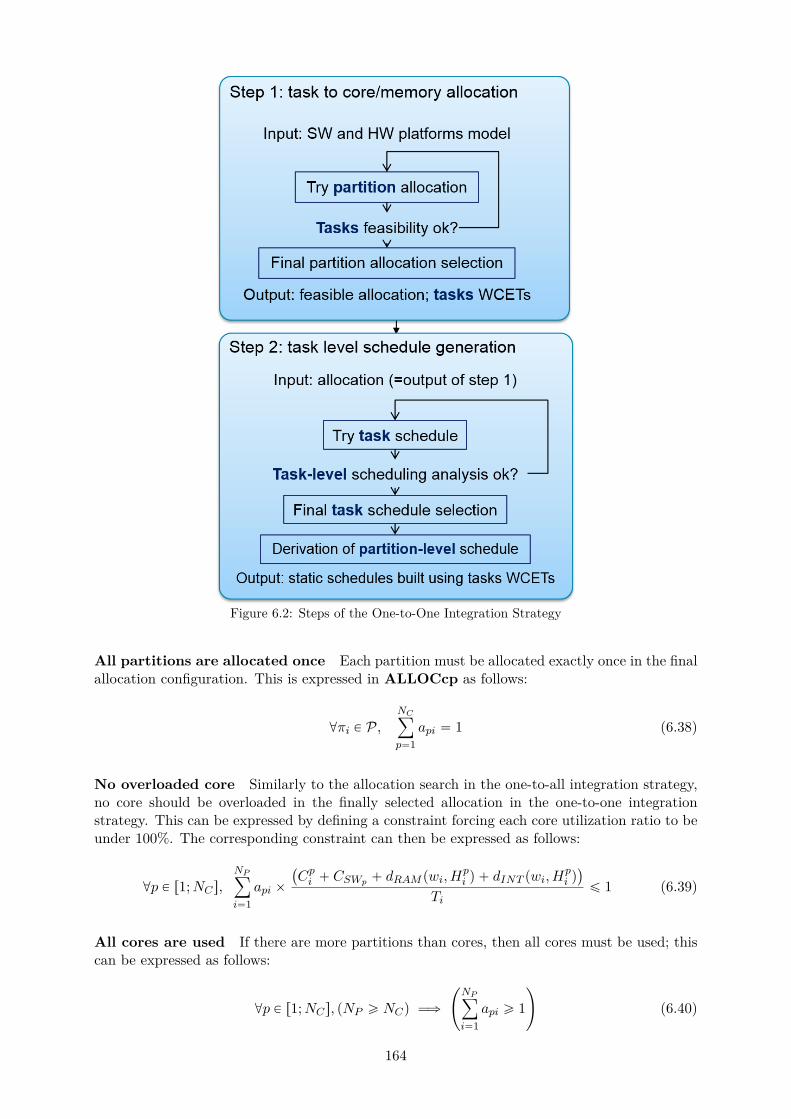
Figure 6.2: Steps of the One-to-One Integration Strategy
All partitions are allocated once Each partition must be allocated exactly once in the finalallocation configuration. This is expressed in ALLOCcp as follows:
@πi P P,NCÿ
p“1api “ 1 (6.38)
No overloaded core Similarly to the allocation search in the one-to-all integration strategy,no core should be overloaded in the finally selected allocation in the one-to-one integrationstrategy. This can be expressed by defining a constraint forcing each core utilization ratio to beunder 100%. The corresponding constraint can then be expressed as follows:
@p P r1;NCs,NPÿ
i“1api ˆ
`
Cpi ` CSWp ` dRAM pwi, Hpi q ` dINT pwi, H
pi q˘
Tiď 1 (6.39)
All cores are used If there are more partitions than cores, then all cores must be used; thiscan be expressed as follows:
@p P r1;NCs, pNP ě NCq ùñ
˜
NPÿ
i“1api ě 1
¸
(6.40)
164

Otherwise, if there are less partitions than the nuomber of cores to be used on the multicore,there should be only one partition per core in the selected allocation, in order to maximize asmuch as possible the number of cores used. This can be expressed as follows:
@p P r1;NCs, pNP ă NCq ùñ
¨
˚
˝
NPÿ
i“1
NPÿ
j“1j‰i
api ˆ apj “ 0
˛
‹
‚
(6.41)
Memory Path Allocation Constraints
This subsection presents all constraints expressed in ALLOCcp that are related to the memorypath allocation.
Epartition is allocated to at least one memory path Each partition should be allocatedto a memory controller. Indeed, if a partition that is not allocated to any memory controller, thenits tasks will not be able to access the main memory at runtime. As such, the following constraintis expressed to ensure that all partitions are allocated to at least one memory controller:
@πi P P,NMCÿ
k“1p2mcki ě 1 (6.42)
All memory paths are used All memory controllers must be used, in order to benefit fromthe available bandwidth and balance memory accesses as much as possible at runtime. This canbe done by expressing the following constraint:
@k P r1;NMCs,NPÿ
i“1p2mcki ě 1 (6.43)
Realistic Memory Path Allocation Another verification that must be performed in relationwith the memory is the coherence of the memory paths allocation with regards to the core-to-memory physical paths, i.e. verifying that the partitions have all been allocated to memorypaths that are actually wired to the core they each have been allocated to. This can be doneby comparing the values of p2mc to c2mc. In particular, a partition cannot be allocated toa path that is not wired to the core it is allocated to. The following equation expresses thecorresponding constraint on the values of a and p2mc:
@k P r1;NMCs,@πi P P,
˜
NCÿ
p“1api ˆ c2mcpk “ 0
¸
ùñ pp2mcki “ 0q (6.44)
Indeed, the first sum enables to retrieve the index of the core p to which πi has been allocated,corresponding to the only non-null term api of the sum. Multiplying this non-nul term byc2mckp for a given memory controller k enables to verify whether core p is physically wired tothe controller k: the total sum is non-null if it is indeed the case, and null otherwise. And ifcore p is not wired to the memory controller k, then any partition πi allocated to core p cannotbe allocated to the memory controller k, i.e. p2mcki must be equal to zero.
Coherent memory path allocation regarding tasks memory footprints In addition,the partition-to-path allocation must be coherent regarding the available memory space perpath and the memory contexts of partitions allocated to each path. The following equation can
165

be embedded as a constraint of the allocation problem in order to verify that the partition-to-memory-controller allocation is coherent with the partitions memory footprint:
@k P r1;NMCs,NPÿ
i“1p2mcki ˆ
¨
˚
˚
˝
NTÿ
j“1pidj“i
tRamj
˛
‹
‹
‚
ď mcSizek (6.45)
Coherent memory path allocation regarding Message-Based Communications If apartition πi is involved in some inter-partition communication with a partition on another core,then both partitions must be able to access the corresponding shared memory area. In ourmodel, communications happen at task level: the sender task must be able to access the samememory area as the receiver task. At partition level, two partitions can be involved in IPC, andboth containing some receiver and some senders. As a consequence, defining a constraint forpath allocation in concordance with communications at task-level may be difficult dependingon the complexity of the data exchanges defined in the software platform. To find a simpleralternative, we decide to specify that two partitions involved in communications with each othershould use the same memory path(s). This corresponds to the following constraint:
@πi, πj P P,
pipcji ` ipcij ‰ 0q ùñˆ
NMCř
k“1p2mcki ˆ p2mckj ě 1
˙
(6.46)
The term pipcji ` ipcijq enables to select couples of partitions pπi, πjq that are involved in inter-partition communications. For such couples, the partitions must have at least one memory pathin common, i.e. there exists at least one memory path index k for which the term p2mckiˆp2mckjis not null.
It is interesting to note that, coupled with an adequate objective function (targeting interfer-ence minimization for instance), this constraint is likely to have the CP solver automatically tryto allocate partitions involved in communications with each other to the same core or directlyto the same memory paths, in order to minimize simultaneous memory access requests, andtherefore, minimize inter-task interference.
Schedulability Constraints
This subsection presents all constraints expressed in ALLOCcp that are related to the veri-fication of timing-related properties of the evaluated allocations. Similarly to step AS1 in theone-to-all integration strategy, these constraints represent the feasibility analysis proposed inthis thesis for early timing analysis and for guiding the allocation search in a safe manner byforcing the choice of allocation to correspond to an allocation that passes the feasibility test.
Message passing and precedence relations As in the one-to-all integration strategy, AL-LOCcp must contain some constraints expressing each task jitter upon first activation Ji ac-cording to its precedence and message relations specified in the software architecture. Indeedas mentioned before, if a task does not have any predecessor or does not receive any messageat runtime, its jitter Ji is null. On the contrary, if a task has predecessors or receives messages,its first activation must correspond to the end of execution of all its predecessors and/or anyproducer of a message it consumes. The equations corresponding to such constraints are thesame as in step AS1 of the one-to-all integration strategy: as such, equations (6.11) and (6.12)defined page 155 are embedded in ALLOCcp as constraints to compute tasks jitters upon firstactivation.
166
Affinities and exclusion constraints The partition-to-core allocation must be in line withpartition-to-core affinities expressed by the module integrator and/or system designers. As such,the following constarint must be expressed:
@p P r1;NCs,@πi P P,`
coreAffpi ě 1˘
ùñ papi ě 1q (6.47)
Similarly, partition-to-partition affinities must be respected in the partition-to-core alloca-tion:
@πi, πj P P,`
partAffij “ 1˘
ùñ
˜
NCÿ
p“1api ˆ apj “ 1
¸
(6.48)
Finally, the partition-to-partition exclusions expressed by the application supplier must bereflected in the selected partition-to-core allocation:
@τi, τj P T ,`
partExij “ 1˘
ùñ
˜
NCÿ
p“1api ˆ apj “ 0
¸
(6.49)
All tasks are schedulable Last but not least, the feasibility of the tasks in the multicoreallocation currently under evaluation is assessed. It is done using the system (5.7) in order tocompute every task WCET wi, WCRT Ri and jitter Ji, but also equation (5.51) in order toverify that all tasks WCRTs remain smaller than the respective deadline.
Objective function
As explained before in the one-to-all integration strategy, the most popular optimization fea-ture for real-time software scheduling is the reduction of CPU workload. In addition to loadbalancing, the workload is proportional to inter-task interference delays, which add up to thetasks executions. Because of these delays, (i) the extra time available before tasks deadlinesare reached at runtime is drastically shortened, and (ii) the integrator is given less flexibilityfor the setting of a valid global schedule for each core in the considered allocation. As such,reducing the total workload thus increases the flexibility of future design choices to be madewhen configuring the task schedule.
The defined objective function to minimize the total workload of the selected solution is thefollowing:
minimizeNCÿ
p“1
˜
NPÿ
i“1api ˆ
NTÿ
j“1PARTij ˆ
Cpi ` dRAM pwi, Hpi q ` dINT pwi, H
pi q
Ti
¸
(6.50)
Schedule generation
Once an allocation is selected, the module integrator then generates a static schedule. Moreprecisely, he generates a task-level schedule, and the corresponding partition schedule is deducedfrom the task-level schedule.
To build a static schedule beforehand while saving time and effort, we propose a CP calledSCHEDcp. In order to guarantee the validity of the generated schedule, SCHEDcp embracesthe schedulability analysis defined in chapter 5.
Inputs of SCHEDcp The inputs of SCHEDcp are the entire software and hardware models(see chapter 4) and the partition-to-core and partition-to-memory path allocations that havebeen produced by ALLOCcp.
167
Variables of SCHEDcp The decision variables of the allocation CP are the tasks activationdates per MAF tOki , along with the task instances WCETs wki . The auxiliary variables are thetasks instances response times Rki derived from each wki , the corresponding CPU time budgetfor each partition and frame Ekj , and the partitions activation dates pOki which are derived fromtheir tasks activation dates.
Outputs of SCHEDcp The output of SCHEDcp is a task-level schedule that is guaranteedto enforce all timing-related constraints of the system. The partition-level schedule is thendeduced from the task-level schedule and the task-to-partition allocation defined by PART .
Schedule Generation Constraints
Task instances definition One of the first constraints to be implemented in SCHEDcp isto ensure each activation date tOki corresponds to the kth instance of τi:
@τi P T ,@k P r1;nbActivis, tOki P rpk ´ 1q ˆ Ti; k ˆ Tis (6.51)
Non-overlapping executions on each core In the schedule to be generated, there shouldalways be at most one running task per core at runtime, as overlapping executions on the samecore are forbidden:
@p P r1;NCs,@τi, τj P T | pi ‰ jq,@pk,mq P v1;nbActiviw ˆ v1;nbActivjw,˜
NCř
p“1ap,pidi ˆ ap,pidj “ 1
¸
ùñ p ptOmj ě ptOki ` w
ki q _ pOki ě tOmj ` w
mj q q
(6.52)
The left-hand side of equation (6.52) forces the execution of one of the two instances to finishbefore the start of the other.
Time sampling according to timer interrupt frequency Tasks instances activation off-sets must be an even multiple of the corresponding core clock frequency.
@τi P T ,@k P v1;nbActiviw, tOki ” 0 mod˜
NCÿ
p“1api ˆ Clkp
¸
(6.53)
Schedule Verification Constraints
Task-level scheduling verification Each task instance execution must complete before thecorresponding deadline. As such, tasks instances WCETs wki are computed first using thesecond equation in system (5.12) for non-preemptive tasks, system (5.11) for preemptive tasks,and equation (5.61) is embedded in SCHEDcp as well to check whether all instances respecttheir deadlines.
Partition-level scheduling verification Analogously at partition-level, all partitions timebudgets must fit in one MAF. To ensure so, the partition level verification for the schedulegeneration problem represented by equation (5.60) is added as a constraint in SCHEDcp.
Message passing and precedence relations The generated activation dates for each taskinstance must be coherent with the message exchanges and precedence relations expressed inthe system’s requirements. This type of requirements has been studied in chapter 5 section 5.5page 143. As such, the following equations must be expressed as constraints of SCHEDcp:
• Equations (5.64) and (5.65) for dependence relations due to precedence relations andmessage-based communications between equiperiodic tasks,
168
• Equations (5.66) and (5.68) for dependence relations where the preceding task is fasterthan the successor task,
• Equations (5.67) and (5.69) for dependence relations where the preceding task is slowerthan the successor task.
Linking inter-task interference with the knowledge of parallel executions Finally, wepresent the CP constraints expressing which equation should be used to compute wki dependingon the presence of other tasks running in parallel. A task instance suffers no interference if it isrunning alone on the entire multicore according to the defined core schedules:
@τi P T ,@k P v1;nbActiviw ,˜
NCř
p“1api ˆ
NTř
j“1p1´ apjq ˆ
nbActivjř
m“1overlappingi,j,k,m “ 0
¸
ùñ
˜
wki “NCř
p“1api ˆ C
pi
¸
(6.54)
If on the contrary, there exist at least one task instance executed in parallel, interferencedelays suffered by τki in the worst-case are not null:
@τi P T ,@k P v1;nbActiviw ,˜
NCř
p“1api ˆ
NTř
j“1p1´ apjq ˆ
nbActivjř
m“1overlappingi,j,k,m ‰ 0
¸
ùñ
˜
wki “NCř
p“1api ˆ C
pi ` dRAM pw
ki , H
pi q ` dINT pw
ki , H
pi q
¸
(6.55)
where dRAM pwki , Hpi q and dINT pwki , H
pi q are computed using equations (5.38) and (5.41) respec-
tively.These two constraints come from commonsense: (i) in general in scheduling problems, sched-
ules often present slack times where the CPU is idle; (ii) if a task instance τki is alone to runon an entire platform, then it has no competition to access the shared resources and thereforesuffers zero interference delay, i.e. in our case, dRAM pwki , H
pi q and dINT pwki , H
pi q are both equal
to zero. Then in such situations, computing wki using equation (5.11) leads to unnecessarypessimism, as wki is actually equal to the execution duration in isolation Cki .
Constraint (6.54) is not essential to scheduling problems as it does not represent a require-ment of the system. However, without constraint (6.54), the corresponding CP expressed is notable to make the link between the temporal location of each task execution time interval in theschedule, with the presence of inter-task interference. If one task instance τki is alone to run onthe multicore for instance, the CP formulation without constraint (6.54) would be unaware ofthe fact that τki has exclusive access to the memory and interconnect and therefore suffers nointerference, and equation (5.11) would then be used, resulting in an overly pessimistic schedule.
To sum up, constraint (6.54) is not essential to the schedule generation problem CP defi-nition as it does not represent a requirement of the system to be configured, but rather to anoptimization feature since it will guide the search towards schedules where the least possibleamount of parallel executions occur for a given software and hardware platforms. As such,constraint (6.54) acts as an optimization feature during system design.
Objective Function The objective function of SCHEDcp can be about CPU workloadreduction:
Minimize maxpPr1;NC s
ˆ
NTř
i“1ap,pidi ˆ
nbActiviř
k“1
´
Cpi `dRAM pwki ,H
pi q`dINT pw
ki ,H
pi q
MAFp
¯
˙
(6.56)
169
6.3 Discussions
One-to-All Strategy: Partitions CPU Time Windows Computation. It is importantto note that in step AS1, application suppliers do not schedule tasks, but rather just computeeach partition time budget Eki per frame in the partition cycle, in order to be able to providethese budgets to the module integrator at the end of step AS1.
The resulting CPU time budgets could then be refined at the end of AS2, i.e. after a task-levelschedule can therefore be configured. This would have enabled to compute each Eki budget usingtasks instances WCETs wmj instead of using the same WCET wj for all instances of τj in onepartition cycle. The result would have been tighter partition windows durations, and possiblyenough room on the corresponding multicore module for scheduling additional partitions.
However, this would have implied adding the WCET equations to AS2cp, along with defin-ing new WCET variables Eki to recompute the new partitions CPU time budgets, and thenperform step MI1 again in order to use these tightened budgets to compute a new partitionschedule, and then re-launch AS2cp in order to perform task-level verification, etc. To sum up,this would have meant increasing the complexity of AS2cp and extending the duration of theintegration process solely for optimization purposes. In this thesis, we made the choice to keepthe proposed strategies as simple as possible in order to gain in time and effort without loosingthe safetiness and confidence in the exploited timing analysis metrics, the pessimism embeddedin the produced bounds being seen as safety margins. This can be seen as interesting futurework.
6.4 Summary
In this chapter we presented the two integration strategies proposed in this thesis for implement-ing multicore-based IMA systems. A general overview was given to ease comparison betweenthe pros and cons of the two strategies, before presenting them in greater extent. Each strategyis divided in chronological steps performed by the different roles involved in the integration pro-cess. For each step, an approach for conducting the required verification and configurations isexpressed. To save time and effort during the process, some steps are expressed through a CP,which formulation has been given as one of the contributions of this thesis. Each CP embedsall needed analyses for the result to be considered safe according to certification standards, andespecially the DO-178.
170

Chapter 7
Evaluation Results
In this chapter, we present the evaluation of our contributions, and the obtained results. Wefirst explain the goal of the tests performed to evaluate our contributions, before presenting theway the case study has been built and describing the hardware architecture. Then in section7.4, we present the results about the evaluation of the gain in time and design optimizationachieved thanks to our approach, and in section 7.3 we present the results of the application ofour approach to a real target.
General Overview
The evaluation phase of the contributions proposed in this thesis is divided in two activities.The first one is the application of the proposed strategies for allocation and scheduling on anIMA case study and for a real target platform. The verification then consists in checking thatno deadline miss occurs at runtime. To do so, a software and a hardware platform must beidentified as inputs to the evaluation. They are modeled as suggested in this thesis, and one ofthe two strategies for allocation and schedule generation search must be applied on them. Theoutcome of the searches is then reproduced in the configuration of the software and hardwareplatforms so that the finally integrated system matches the allocation and the schedule thathave been outputted by our approaches. The final system is then witched on and launchedso that its runtime behavior can be observed. The applied strategy passes the evaluation forthe given input platforms if no deadline miss occurs after a long period of observation. Severalinput situations can be evaluated: for instance, one can vary the number of cores to be usedat runtime on the target platform. The absence of deadline miss in all situations ensures thevalidity of the generated schedule, but also the validity of the produced WCET upper-bounds.Such evaluation, along with the corresponding results, are described in section 7.3.
The second evaluation activity is theoretical, and focused on the allocation and schedulingsearch problems: we compare the solutions obtained when using one of our strategies against thesolutions obtained when multicore interference is not taken into account. To do so, we proceedthe same way as for the evaluation on a real target, without actually implementing the resultingallocation and schedule on the target; this is repeated twice per situation: once as suggestedin this thesis, and another time while ignoring multicore interference in the computation oftasks WCET and WCRT, while still computing them in order to get the corresponding inter-task interference upper bound as computed in our models. The second run is also referred toin this thesis as theoretical allocation and schedule generation search, or interference-obliviousallocation and schedule generation search. For the same situation, the outputs of the two runsare compared in terms of average multicore interference, total workload and slowdown sufferedby tasks due to multicore interference. The second test enables us to assess the optimizationgain achieved thanks to our approach. Such evaluation, along with the corresponding results,are described in section 7.4.
For both activities, the same software case study an hardware platform models have been
171
exploited. As no real IMA software was made available for use in the context of this thesis, webuilt our own case study. The rest of this chapter is organized as follows. We first present thesoftware platform exploited in our tests, along with the corresponding explanations on how it hasbeen built. We then present the hardware platform and its corresponding model, built followingthe approach proposed in this thesis. The results of the evaluation on a real platform is thenpresented, before introducing the theoretical comparison of our contributions with interference-oblivious allocation and scheduling searches. Finally, a section about certification considerationsassesses our work compared to certification objectives currently set for multicore based IMAsystems. This chapter then concludes with a ”Discussions” section about the shortcomings andlimitations of the evaluation regarding the reality of COTS, and a section summarizing thecontent of this chapter.
7.1 Software Case Study Generation
Our contributions being specific to aerospace industries, the ideal evaluation phase should havebeen performed with actual, IMA software. However in practice, for the sake of core businessprotection, the access to such software is often either confidential or carefully restricted. Assuch, it has not been possible to have access to actual IMA software in the context of this thesis.Instead of using actual software for the evaluation of this thesis, we built a mock IMA case studybased on an academic, non-IMA avionics software architecture [108], open source benchmarksof the TACLeBench benchmark suite [13], and our knowledge of IMA architectures and IMAorders of values for each parameters such as partitions periods or MAF values. We describe inthis section how the exploited software case study has been built.
General Architecture
The authors of [108] present a military avionics case study to be used for academic purposes.In this case study, the architecture of nine software functions are described in terms of tasks.For each task, the corresponding scheduling parameters are given, such as information on theirperiodicity or approximate duration in average on a single-core platform.
We took the case study in [108] as a basis and adapted it as follows:
• Software functions have been identified as one or several partitions;
• Tasks periods have been modified so that they consist of harmonic sets;
• Partitions periods have been set as equal to the smallest period of their respective tasks;
• Aperiodic tasks are turned into periodic ones by assigning them a period equal to theperiod of their respective partitions;
• Benchmarks from the TaCLEbench benchmark suite [13] have been used in order to con-struct tasks entry points based on their respective average duration in single-core environ-ments.
The resulting software architecture consists in nine partitions and twenty nine tasks in total (cf.table 7.1).
The next step of building our case study consists in selecting the benchmarks to be exploitedfor each task entry point. To do so, each benchmark of the TACLEBench benchmark suite areanalyzed in order to get an upper bound on their respective single-core execution duration andmaximum number of main memory access. The resulting values will determine which benchmarkis selected for which task. This is done as a part of the preliminary analysis required in thecontributions proposed in this thesis, and explained in the next subsection.
172

Figure 7.1: Benchmark Selection Process [9]
Preliminary Analysis and Benchmark selection
One criteria of benchmark selection that is important when evaluating our work is the rate atwhich access to the main memory is requested at runtime. It must be realistic and match theexpected access rate for multicore COTS currently under industrial evaluation for future usage.To our knowledge, this corresponds to a memory access rate of 20 000 requests per millisecondapproximately.
The memory access rate parameter of benchmarks is linked to the maximum number ofmemory access requests that can be generated by a task, Hi, depending on the benchmarkscalled in its entry point. Another parameter of benchmarks which has an influence on a taskcalling it in its entry point is its execution duration in isolation.
Regarding tasks, two important parameters of the model of a task τi that must be given asinputs for the timing analysis and the integration strategies activities, are upper bounds on theexecution duration in isolation Ci and the maximum number of main memory access requests perexecution Hi. These two parameters are extracted from single-core analysis performed on thetasks respective entry points using aiT. In the software case study exploited for the evaluationphase of this thesis, tasks entry points consist in one or several calls to one of the TACLeBenchbenchmark suite.
One unique benchmark is selected as a unitary benchmark, and exploited for all entry pointsin order to enforce the same memory access rate for all tasks of the software platform. Thenumber of times the benchmark is called in each entry point varies from one task to the other:for a given task τi, the selected benchmark is called as many times as needed in order for theresulting entry point to have an execution duration in isolation as close as possible to Ci. Todo so, one must know the execution duration in isolation of the benchmark. In fact, as illus-trated in figure 7.1, the execution duration in isolation of benchmarks actually is one of the twocriterion for benchmark selection, the first one being the memory access rate which must be asclose as possible to 20000 requests per millisecond. Indeed, the selected benchmark must havean execution duration in isolation that corresponds to a value that is smaller than or equal tothe smallest Ci of the software architecture. The reason is that it must be possible to call theselected benchmark one or several times in each task entry point so that the final entry pointhas a duration in isolation as close as possible to the corresponding Ci value given in [108].For instance if a benchmark matches regarding its memory access rate but has a duration inisolation in seconds while most of the tasks have durations in milliseconds, then the benchmark
173
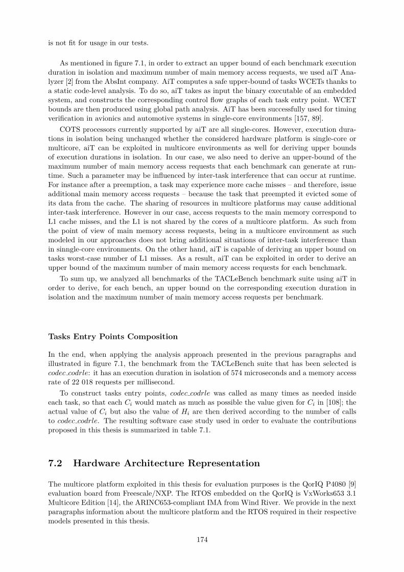
is not fit for usage in our tests.
As mentioned in figure 7.1, in order to extract an upper bound of each benchmark executionduration in isolation and maximum number of main memory access requests, we used aiT Ana-lyzer [2] from the AbsInt company. AiT computes a safe upper-bound of tasks WCETs thanks toa static code-level analysis. To do so, aiT takes as input the binary executable of an embeddedsystem, and constructs the corresponding control flow graphs of each task entry point. WCETbounds are then produced using global path analysis. AiT has been successfully used for timingverification in avionics and automotive systems in single-core environments [157, 89].
COTS processors currently supported by aiT are all single-cores. However, execution dura-tions in isolation being unchanged whether the considered hardware platform is single-core ormulticore, aiT can be exploited in multicore environments as well for deriving upper boundsof execution durations in isolation. In our case, we also need to derive an upper-bound of themaximum number of main memory access requests that each benchmark can generate at run-time. Such a parameter may be influenced by inter-task interference that can occur at runtime.For instance after a preemption, a task may experience more cache misses – and therefore, issueadditional main memory access requests – because the task that preempted it evicted some ofits data from the cache. The sharing of resources in multicore platforms may cause additionalinter-task interference. However in our case, access requests to the main memory correspond toL1 cache misses, and the L1 is not shared by the cores of a multicore platform. As such fromthe point of view of main memory access requests, being in a multicore environment as suchmodeled in our approaches does not bring additional situations of inter-task interference thanin sinngle-core environments. On the other hand, aiT is capable of deriving an upper bound ontasks worst-case number of L1 misses. As a result, aiT can be exploited in order to derive anupper bound of the maximum number of main memory access requests for each benchmark.
To sum up, we analyzed all benchmarks of the TACLeBench benchmark suite using aiT inorder to derive, for each bench, an upper bound on the corresponding execution duration inisolation and the maximum number of main memory access requests per benchmark.
Tasks Entry Points Composition
In the end, when applying the analysis approach presented in the previous paragraphs andillustrated in figure 7.1, the benchmark from the TACLeBench suite that has been selected iscodec codrle: it has an execution duration in isolation of 574 microseconds and a memory accessrate of 22 018 requests per millisecond.
To construct tasks entry points, codec codrle was called as many times as needed insideeach task, so that each Ci would match as much as possible the value given for Ci in [108]; theactual value of Ci but also the value of Hi are then derived according to the number of callsto codec codrle. The resulting software case study used in order to evaluate the contributionsproposed in this thesis is summarized in table 7.1.
7.2 Hardware Architecture Representation
The multicore platform exploited in this thesis for evaluation purposes is the QorIQ P4080 [9]evaluation board from Freescale/NXP. The RTOS embedded on the QorIQ is VxWorks653 3.1Multicore Edition [14], the ARINC653-compliant IMA from Wind River. We provide in the nextparagraphs information about the multicore platform and the RTOS required in their respectivemodels presented in this thesis.
174
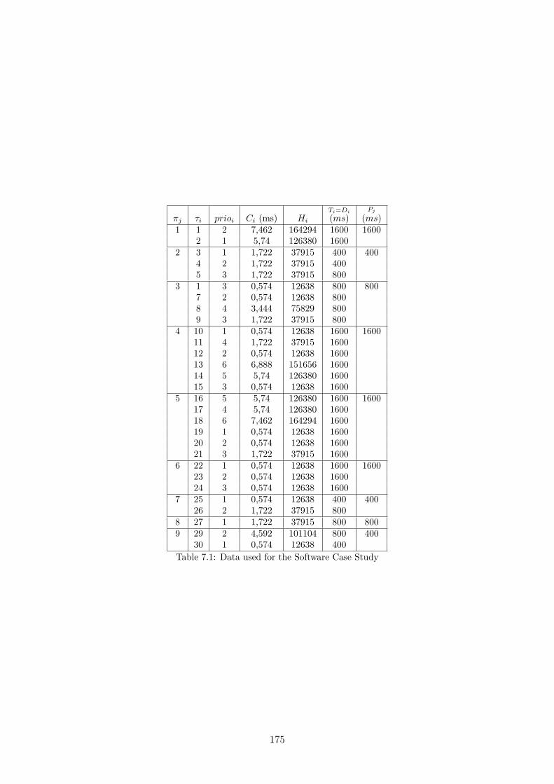
πj τi prioi Ci (ms) Hi
Ti“Di
pmsqPj
pmsq1 1 2 7,462 164294 1600 1600
2 1 5,74 126380 16002 3 1 1,722 37915 400 400
4 2 1,722 37915 4005 3 1,722 37915 800
3 1 3 0,574 12638 800 8007 2 0,574 12638 8008 4 3,444 75829 8009 3 1,722 37915 800
4 10 1 0,574 12638 1600 160011 4 1,722 37915 160012 2 0,574 12638 160013 6 6,888 151656 160014 5 5,74 126380 160015 3 0,574 12638 1600
5 16 5 5,74 126380 1600 160017 4 5,74 126380 160018 6 7,462 164294 160019 1 0,574 12638 160020 2 0,574 12638 160021 3 1,722 37915 1600
6 22 1 0,574 12638 1600 160023 2 0,574 12638 160024 3 0,574 12638 1600
7 25 1 0,574 12638 400 40026 2 1,722 37915 800
8 27 1 1,722 37915 800 8009 29 2 4,592 101104 800 400
30 1 0,574 12638 400Table 7.1: Data used for the Software Case Study
175
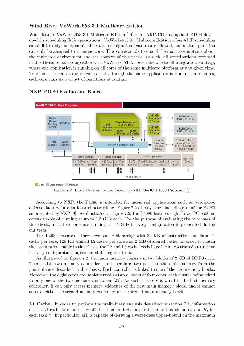
Wind River VxWorks653 3.1 Multicore Edition
Wind River’s VxWorks653 3.1 Multicore Edition [14] is an ARINC653-compliant RTOS devel-oped for scheduling IMA applications. VxWorks653 3.1 Multicore Edition offers AMP schedulingcapabilities only: no dynamic allocation or migration features are allowed, and a given partitioncan only be assigned to a unique core. This corresponds to one of the main assumptions aboutthe multicore environment and the context of this thesis; as such, all contributions proposedin this thesis remain compatible with VxWorks653 3.1, even the one-to-all integration strategy,where one application is running on all cores of the same multicore platform at any given time.To do so, the main requirement is that although the same application is running on all cores,each core runs its own set of partitions at runtime.
NXP P4080 Evaluation Board
Figure 7.2: Block Diagram of the Freescale/NXP QorIQ P4080 Processor [9]
According to NXP, the P4080 is intended for industrial applications such as aerospace,defense, factory automation and networking. Figure 7.2 displays the block diagram of the P4080as presented by NXP [9]. As illustrated in figure 7.2, the P4080 features eight PowerPC e500mccores capable of running at up to 1,5 GHz each. For the purpose of evaluating the outcomes ofthis thesis, all active cores are running at 1,5 GHz in every configuration implemented duringour tests.
The P4080 features a three level cache hierarchy, with 32 KB of instruction and data L1cache per core, 128 KB unified L2 cache per core and 2 MB of shared cache. In order to matchthe assumptions made in this thesis, the L2 and L3 cache levels have been deactivated at runtimein every configuration implemented during our tests.
As illustrated on figure 7.2, the main memory consists in two blocks of 2 GB of DDR3 each.There exists two memory controllers, and therefore, two paths to the main memory from thepoint of view described in this thesis. Each controller is linked to one of the two memory blocks.Moreover, the eight cores are implemented as two clusters of four cores, each cluster being wiredto only one of the two memory controllers [29]. As such, if a core is wired to the first memorycontroller, it can only access memory addresses of the first main memory block, and it cannotaccess neither the second memory controller or the second main memory block.
L1 Cache In order to perform the preliminary analysis described in section 7.1, informationon the L1 cache is required by aiT in order to derive accurate upper bounds on Ci and Hi foreach task τi. In particular, aiT is capable of deriving a worst-case upper-bound on the maximum
176
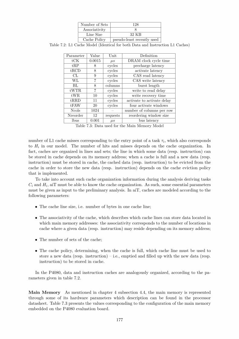
Number of Sets 128Associativity 8
Line Size 32 KBCache Policy pseudo-least recently used
Table 7.2: L1 Cache Model (Identical for both Data and Instruction L1 Caches)
Parameter Value Unit DefinitiontCK 0.0015 µs DRAM clock cycle timetRP 8 cycles precharge latency
tRCD 8 cycles activate latencyCL 9 cycles CAS read latencyWL 7 cycles CAS write latencyBL 8 columns burst length
tWTR 7 cycles write to read delaytWR 10 cycles write recovery timetRRD 11 cycles activate to activate delaytFAW 20 cycles four activate windowsNcols 1024 – number of columns per row
Nreorder 12 requests reordering window sizelbus 0.001 µs bus latency
Table 7.3: Data used for the Main Memory Model
number of L1 cache misses corresponding to the entry point of a task τi, which also correspondsto Hi in our model. The number of hits and misses depends on the cache organization. Infact, caches are organized in lines and sets; the line in which some data (resp. instruction) canbe stored in cache depends on its memory address; when a cache is full and a new data (resp.instruction) must be stored in cache, the cached data (resp. instruction) to be evicted from thecache in order to store the new data (resp. instruction) depends on the cache eviction policythat is implemented.
To take into account such cache organization information during the analysis deriving tasksCi and Hi, aiT must be able to know the cache organization. As such, some essential parametersmust be given as input to the preliminary analysis. In aiT, caches are modeled according to thefollowing parameters:
• The cache line size, i.e. number of bytes in one cache line;
• The associativity of the cache, which describes which cache lines can store data located inwhich main memory addresses: the associativity corresponds to the number of locations incache where a given data (resp. instruction) may reside depending on its memory address;
• The number of sets of the cache;
• The cache policy, determining, when the cache is full, which cache line must be used tostore a new data (resp. instruction) – i.e., emptied and filled up with the new data (resp.instruction) to be stored in cache.
In the P4080, data and instruction caches are analogously organized, according to the pa-rameters given in table 7.2.
Main Memory As mentioned in chapter 4 subsection 4.4, the main memory is representedthrough some of its hardware parameters which description can be found in the processordatasheet. Table 7.3 presents the values corresponding to the configuration of the main memoryembedded on the P4080 evaluation board.
177

7.3 Validation on a Real Target
In this section, we describe the conclusions that could be drawn when we implemented thescheduling tables generated by our approach, on our HW platform to validate accuracy comparedto reality of industrial systems and platforms.
Configuration Setup
The goal of this evaluation is to implement the configurations selected as output of our allocationand scheduling CP on a real target, and verify that no deadline miss occurs at runtime afterobserving several MAFs. If no deadline miss is indeed observed, two conclusions can be drawn :
• The timing analysis produced accurate WCET bounds for each task, and
• The partitions time windows and the generated schedules are accurately chosen, i.e. theyenable to accurately respect all timing requirements of the system.
The evaluation process corresponding to such verification is the following:
• Step 1: Select a hardware configuration (CPU clock frequency, number of cores to be used,etc.) and an integration strategy to be implemented (one-to-one or one-to-all);
• Step 2: Perform the preliminary analysis enabling to obtain the Ci and Hi parametersfor each task of the software platform; in the context of our evaluation tests, this stepis only done once since the same software case study is exploited for all implementedconfigurations.
• Step 3: Run the allocation and scheduling CP problems corresponding to the integrationstrategy selected in step 1, and get the resulting solution;
• Step 4: Configure the hardware platform according to the configuration set in step 1 andthe allocation and schedule selected in step 3. Figure 7.3) illustrates some configurationsperformed in this step.
• Step 5: Compile, boot and run on the embedded target, and check that no deadline ismissed at runtime;
• Step 6: Repeat steps 1 to 7 for various parameters values in step 1 (number of cores used,strategy of integration, etc.)
For each of the one-to-one and one-to-all integration strategies, the process from step 1 to6 is repeated several times since we varied the number of cores to be used on the P4080. Themaximum possible number of cores is eight, corresponding to the situation where each partitionis allocated alone on a core. Setting the number of cores to be used at runtime as the variableparameters of the tests allows a comparison of results obtained for a given strategy dependingon the number of cores used, for instance in order to follow the evolution of the WCET boundsor the difference between computed WCETs and measured execution times. It also enables thecomparison of both strategies with each other and the evolution of the results they provide withthe number of cores. The corresponding results are presented in the next subsection.
Results
In both strategies, solutions – i.e. a SW/HW allocation and a schedule where all deadlines aremet within a complete MAF – were found for up to five cores. Indeed, no solution has beenfound for six to eight cores for the given software case study and hardware configuration. Thetiming analyses proposed in this thesis relying on sufficient feasibility and scheduling conditions,this means the allocation CPs for each strategy respectively did not find an allocation in which
178
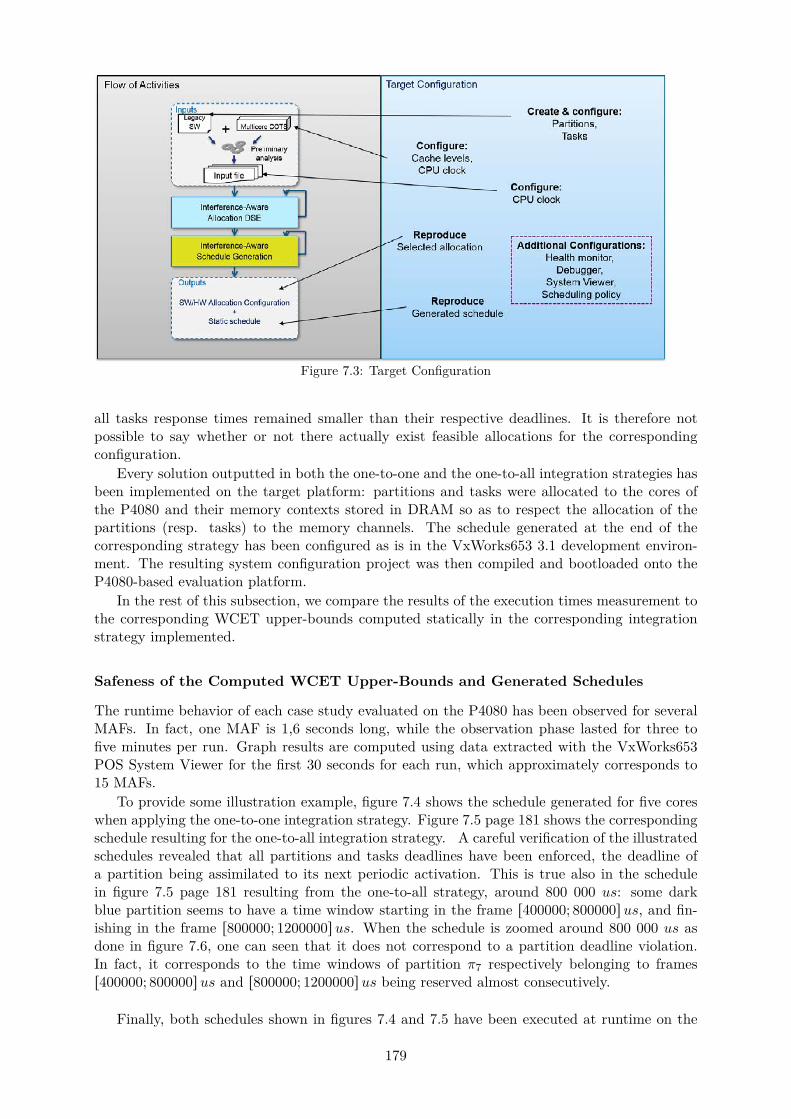
Figure 7.3: Target Configuration
all tasks response times remained smaller than their respective deadlines. It is therefore notpossible to say whether or not there actually exist feasible allocations for the correspondingconfiguration.
Every solution outputted in both the one-to-one and the one-to-all integration strategies hasbeen implemented on the target platform: partitions and tasks were allocated to the cores ofthe P4080 and their memory contexts stored in DRAM so as to respect the allocation of thepartitions (resp. tasks) to the memory channels. The schedule generated at the end of thecorresponding strategy has been configured as is in the VxWorks653 3.1 development environ-ment. The resulting system configuration project was then compiled and bootloaded onto theP4080-based evaluation platform.
In the rest of this subsection, we compare the results of the execution times measurement tothe corresponding WCET upper-bounds computed statically in the corresponding integrationstrategy implemented.
Safeness of the Computed WCET Upper-Bounds and Generated Schedules
The runtime behavior of each case study evaluated on the P4080 has been observed for severalMAFs. In fact, one MAF is 1,6 seconds long, while the observation phase lasted for three tofive minutes per run. Graph results are computed using data extracted with the VxWorks653POS System Viewer for the first 30 seconds for each run, which approximately corresponds to15 MAFs.
To provide some illustration example, figure 7.4 shows the schedule generated for five coreswhen applying the one-to-one integration strategy. Figure 7.5 page 181 shows the correspondingschedule resulting for the one-to-all integration strategy. A careful verification of the illustratedschedules revealed that all partitions and tasks deadlines have been enforced, the deadline ofa partition being assimilated to its next periodic activation. This is true also in the schedulein figure 7.5 page 181 resulting from the one-to-all strategy, around 800 000 us: some darkblue partition seems to have a time window starting in the frame r400000; 800000sus, and fin-ishing in the frame r800000; 1200000sus. When the schedule is zoomed around 800 000 us asdone in figure 7.6, one can seen that it does not correspond to a partition deadline violation.In fact, it corresponds to the time windows of partition π7 respectively belonging to framesr400000; 800000sus and r800000; 1200000sus being reserved almost consecutively.
Finally, both schedules shown in figures 7.4 and 7.5 have been executed at runtime on the
179

Figure 7.4: Schedule Resulting from Applying the One-to-One Integration Strategy to Integrate the SWCase Study on Five Cores of the P4080
180

Figure 7.5: Schedule Resulting from Applying the One-to-All Integration Strategy to Integrate the SWCase Study on Five Cores of the P4080
target platform, leading to a respective runtime behavior free of deadline miss.In general, for all the test configurations evaluated on the target platform, no deadline miss
has been observed at runtime either. As such, the evaluation results of this thesis enabled anempirical validation of the safeness of the produced WCET bounds, the timing analysis and ingeneral, the allocation and schedule generation processes.
To conclude, the presence of a significant amount of slack times in the scheduled illustratedin figures 7.4 and 7.5 shows that more than just the nine partitions of the exploited softwarecase study could potentially be allocated to the five cores of the P4080, which is promising forthe SWaP reduction capabilities of the one-to-one and one-to-all integration strategies.
Figure 7.6: Parallel Execution of Non-Interfering Tasks
Analysis of the Embedded Pessimism
The exact pessimism of the produced WCET upper-bounds cannot be known for certainty. Assuch, the difference observed between computed WCETs and maximum measured ETs consist inthe maximum possible value of the actual pessimism of the timing analysis approach proposedin this thesis. However, in order to simplify the explanations in the rest of this chapter, andwhenever there is no ambiguity, the difference observed between computed WCET upper-boundsand maximum measured ETs is sometimes also referred to as pessimism.
Figure 7.7 illustrates the evolution with the number of cores of the total difference betweencomputed WCETs and measured WCETs in percentage and in each strategy respectively. In thesingle core case, the computed WCET upper-bounds present around 94.5% pessimism in bothstrategies. In the one-to-one integration strategy, the percentage of pessimism is stable aroundthat value when the number of cores increases. On the other hand in the one-to-all integrationstrategy, the maximum pessimism is observed for two and three cores with around 97.5 %. Itthen decreases to 97 % and 96 % for four and five cores respectively.
181

Figure 7.7: Comparison of the Observed Difference between Computed WCETs and the RespectiveMaximum Measured ETs in each Strategy
Without specific tools such as a probe for detailed trace analysis, it is not possible to examinethe cause of this decrease. Multicore interference is not to blame since according to the resultsfiles, there is no multicore interference in the schedule, due to never overlapping tasks that shareaccess to the same memory controller. The variability of runtime execution and the randomnessof the measured execution times values may be responsible for the pessimism decrease whenusing five cores instead of four. Another factor ma be the fact that allocations lead to differentWCETs depending on the number of context switches occurring on each core: in fact, when dis-patching the same number of non-preemptive tasks to a greater number of cores, fewer contextswitchings occur in one MAF.
An overall observation that can be made from the results displayed in figure 7.7 is the factthat the observed pessimism does not excessively increase with the number of cores. This is aninteresting characteristic of our approach, as it could be used to determine the number of coresof a multicore to be used in the final system depending on the percentage of pessimism toleratedby system designers.
Another observation that can be made is the fact that the pessimism value is close to 100%,which may seem to be a bad news. However, to our knowledge, rumor – at least in the academiccommunity – has it that 100 % pessimism remains smaller than the percentage of pessimismthat industries are ready to consider adding to measurement-based ET bounds for their futuremulticore-based systems, which stands around 200%. Such a margin is said to be added tomeasured maximum ETs with the hope that it will cover the worst-case scenario of interferencelatencies. Such an approach offers no guarantee since it relies on measurements, contrary tothe work in this thesis, which relies on static analysis to produce safe WCET upper-bounds.As such, the safeness of the bounds produced by the timing analysis approach in this thesis,combined to the fact that the obtained pessimism after empirical verification on a real platformremains smaller than the 200 % rumored margin to be considered in future systems, comfortsus in the fact that results showing 95 % of measured pessimism do not limit the interest thatindustries may have in implementing one of the two integration strategies presented in this thesis.
In the WCET upper-bounds pessimism, there already is a pessimism margin that can be
182
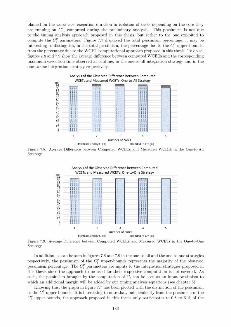
blamed on the worst-case execution duration in isolation of tasks depending on the core theyare running on Cpi , computed during the preliminary analysis. This pessimism is not dueto the timing analysis approach proposed in this thesis, but rather to the one exploited tocompute the Cpi parameters. Figure 7.7 displayed the total pessimism percentage; it may beinteresting to distinguish, in the total pessimism, the percentage due to the Cpi upper-bounds,from the percentage due to the WCET computational approach proposed in this thesis. To do so,figures 7.8 and 7.9 show the average difference between computed WCETs and the correspondingmaximum execution time observed at runtime, in the one-to-all integration strategy and in theone-to-one integration strategy respectively.
Figure 7.8: Average Difference between Computed WCETs and Measured WCETs in the One-to-AllStrategy
Figure 7.9: Average Difference between Computed WCETs and Measured WCETs in the One-to-OneStrategy
In addition, as can be seen in figures 7.8 and 7.9 in the one-to-all and the one-to-one strategiesrespectively, the pessimism of the Cpi upper-bounds represents the majority of the observedpessimism percentage. The Cpi parameters are inputs to the integration strategies proposed inthis thesis since the approach to be used for their respective computation is not covered. Assuch, the pessimism brought by the computation of Ci can be seen as an input pessimism towhich an additional margin will be added by our timing analysis equations (see chapter 5).
Knowing this, the graph in figure 7.7 has been plotted with the distinction of the pessimismof the Cpi upper-bounds. It is interesting to note that, independently from the pessimism of theCpi upper-bounds, the approach proposed in this thesis only participates to 0,8 to 6 % of the
183

total pessimism, which is very promising for the contributions of this thesis.
Figure 7.10 presents a zoom in on the evolution of the pessimism percentage due to the thesiswork, in order to ease the analysis of that pessimism.
Figure 7.10: Pessimism Percentage due to the Timing Analysis Independently from the Pessimism re-sulting from the Preliminary – Single-Core – Analysis
In the one-to-one integration strategy, the evolution of the pessimism introduced by ourtiming analysis has a similar evolution to the total pessimism shown in figure 7.7. Indeed, itremains constant around 0,8 %, independently of the number of active cores. In the one-to-allintegration strategy however, the evolution is similar to the total pessimism except for five cores:it increases while the total pessimism shown in figure 7.7 decreases. As such, for five cores, eventhough the total pessimism is slightly lower than with four cores for instance, the percentage ofthat total pessimism that is to blame on the timine analysis proposed in this thesis increased.This may seem counter-intuitive when comparing both graphs, and yet figure 7.10 representsanother illustration of the dark grey parts of the graph in figure 7.7 by reusing the same data.
The difference between pessimisms (would it be total or exclusively due to the approach inthis thesis), along with the decrease while the number of cores increases, might be explained bythree facts. The first one is the fact that every data is computed in average, thus showing ageneral tendency that does not reflect what happens for each core separately.
The second fact is that the P4080 embraces various heuristics for average execution timesoptimizations that are undisclosed to the public, and which may have impacted the tasks exe-cution at runtime.
The last fact is that upon creation of an integration project, kernel-level management tasksare created, and regularly executed at runtime independently of the tasks defined by the systemdesigner. As such, at runtime, at every clock tick, kernel routines are executed at an hypervisoror supervisor level, contrary to tasks of the SW platform which are user level. As such, thesemanagement tasks are able to interrupt a user task to execute a specific routine. Unfortunately,without execution tracing capabilities as would be provided with a probe for instance, the timeinterval during which the management task was running on the corresponding core will thenbe seen during our observation phase as a time interval during which the user task itself wasrunning. The corresponding task execution duration is then seen as bigger than it actually wasthe case. All the while, the schedule computed as output of the one-to-all strategy revealed the
184
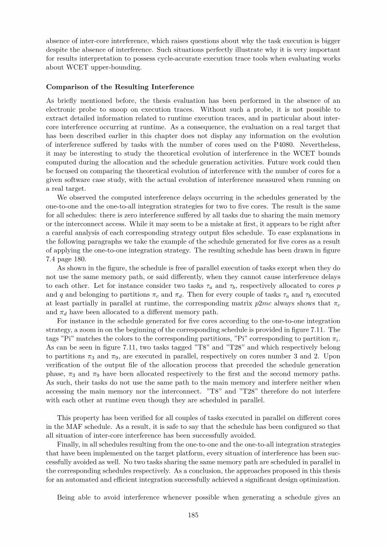
absence of inter-core interference, which raises questions about why the task execution is biggerdespite the absence of interference. Such situations perfectly illustrate why it is very importantfor results interpretation to possess cycle-accurate execution trace tools when evaluating worksabout WCET upper-bounding.
Comparison of the Resulting Interference
As briefly mentioned before, the thesis evaluation has been performed in the absence of anelectronic probe to snoop on execution traces. Without such a probe, it is not possible toextract detailed information related to runtime execution traces, and in particular about inter-core interference occurring at runtime. As a consequence, the evaluation on a real target thathas been described earlier in this chapter does not display any information on the evolutionof interference suffered by tasks with the number of cores used on the P4080. Nevertheless,it may be interesting to study the theoretical evolution of interference in the WCET boundscomputed during the allocation and the schedule generation activities. Future work could thenbe focused on comparing the theoretical evolution of interference with the number of cores for agiven software case study, with the actual evolution of interference measured when running ona real target.
We observed the computed interference delays occurring in the schedules generated by theone-to-one and the one-to-all integration strategies for two to five cores. The result is the samefor all schedules: there is zero interference suffered by all tasks due to sharing the main memoryor the interconnect access. While it may seem to be a mistake at first, it appears to be right aftera careful analysis of each corresponding strategy output files schedule. To ease explanations inthe following paragraphs we take the example of the schedule generated for five cores as a resultof applying the one-to-one integration strategy. The resulting schedule has been drawn in figure7.4 page 180.
As shown in the figure, the schedule is free of parallel execution of tasks except when they donot use the same memory path, or said differently, when they cannot cause interference delaysto each other. Let for instance consider two tasks τa and τb, respectively allocated to cores pand q and belonging to partitions πc and πd. Then for every couple of tasks τa and τb executedat least partially in parallel at runtime, the corresponding matrix p2mc always shows that πcand πd have been allocated to a different memory path.
For instance in the schedule generated for five cores according to the one-to-one integrationstrategy, a zoom in on the beginning of the corresponding schedule is provided in figure 7.11. Thetags ”Pi” matches the colors to the corresponding partitions, ”Pi” corresponding to partition πi.As can be seen in figure 7.11, two tasks tagged ”T8” and ”T28” and which respectively belongto partitions π3 and π9, are executed in parallel, respectively on cores number 3 and 2. Uponverification of the output file of the allocation process that preceded the schedule generationphase, π3 and π9 have been allocated respectively to the first and the second memory paths.As such, their tasks do not use the same path to the main memory and interfere neither whenaccessing the main memory nor the interconnect. ”T8” and ”T28” therefore do not interferewith each other at runtime even though they are scheduled in parallel.
This property has been verified for all couples of tasks executed in parallel on different coresin the MAF schedule. As a result, it is safe to say that the schedule has been configured so thatall situation of inter-core interference has been successfully avoided.
Finally, in all schedules resulting from the one-to-one and the one-to-all integration strategiesthat have been implemented on the target platform, every situation of interference has been suc-cessfully avoided as well. No two tasks sharing the same memory path are scheduled in parallel inthe corresponding schedules respectively. As a conclusion, the approaches proposed in this thesisfor an automated and efficient integration successfully achieved a significant design optimization.
Being able to avoid interference whenever possible when generating a schedule gives an
185
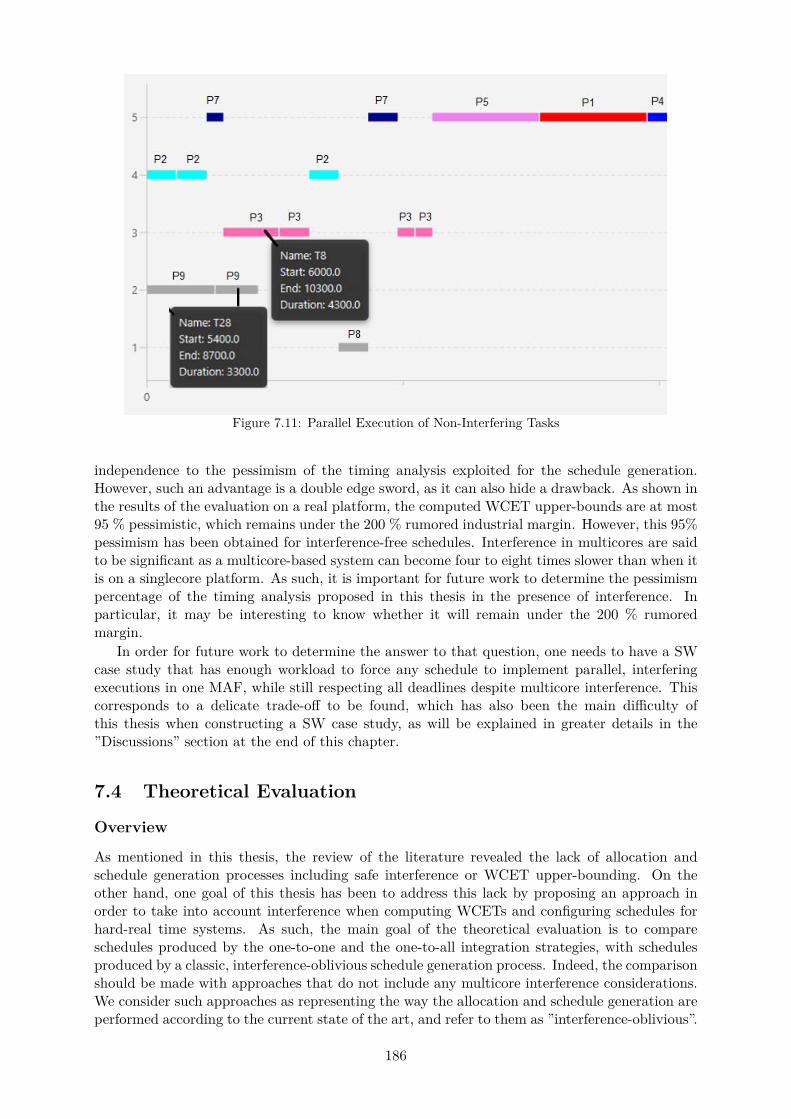
Figure 7.11: Parallel Execution of Non-Interfering Tasks
independence to the pessimism of the timing analysis exploited for the schedule generation.However, such an advantage is a double edge sword, as it can also hide a drawback. As shown inthe results of the evaluation on a real platform, the computed WCET upper-bounds are at most95 % pessimistic, which remains under the 200 % rumored industrial margin. However, this 95%pessimism has been obtained for interference-free schedules. Interference in multicores are saidto be significant as a multicore-based system can become four to eight times slower than when itis on a singlecore platform. As such, it is important for future work to determine the pessimismpercentage of the timing analysis proposed in this thesis in the presence of interference. Inparticular, it may be interesting to know whether it will remain under the 200 % rumoredmargin.
In order for future work to determine the answer to that question, one needs to have a SWcase study that has enough workload to force any schedule to implement parallel, interferingexecutions in one MAF, while still respecting all deadlines despite multicore interference. Thiscorresponds to a delicate trade-off to be found, which has also been the main difficulty ofthis thesis when constructing a SW case study, as will be explained in greater details in the”Discussions” section at the end of this chapter.
7.4 Theoretical Evaluation
Overview
As mentioned in this thesis, the review of the literature revealed the lack of allocation andschedule generation processes including safe interference or WCET upper-bounding. On theother hand, one goal of this thesis has been to address this lack by proposing an approach inorder to take into account interference when computing WCETs and configuring schedules forhard-real time systems. As such, the main goal of the theoretical evaluation is to compareschedules produced by the one-to-one and the one-to-all integration strategies, with schedulesproduced by a classic, interference-oblivious schedule generation process. Indeed, the comparisonshould be made with approaches that do not include any multicore interference considerations.We consider such approaches as representing the way the allocation and schedule generation areperformed according to the current state of the art, and refer to them as ”interference-oblivious”.
186

This section describes the comparison of the schedules resulting from applying the threeprocesses on the same input problem, i.e. the software and hardware platforms. As mentionedbefore, the goal is to compare the solution returned by applying one of the two strategiesproposed in this thesis, with the solution that would have been provided by an interference-oblivious allocation and schedule generation strategy. The comparison of the resulting threeschedules is made on the basis of the total workload, the interference percentage in that workload,and the average slowdown suffered by tasks.
Configuration Setup
In the theoretical evaluation, the number of cores NC P r1; 8s on which to allocate the softwareplatform described in table 7.1 is the only variable parameter. The maximum possible numberof cores is eight, corresponding to the situation where each partition is allocated alone on acore. The result of the integration process – allocation and schedule generation – is either avalid SW/HW allocation and schedule, or the answer that there exists no valid solution for thenumber of cores considered.
The evaluation process corresponding to such a comparison is the following:
• Step 1: Select a hardware configuration (number of cores to be used, etc.) and an integra-tion strategy to be implemented (one-to-one or one-to-all);
• Step 2: Perform the preliminary analysis enabling to obtain the Ci and Hi parametersfor each task of the software platform; in the context of our evaluation tests, this stepis only done once since the same software case study is exploited for all implementedconfigurations.
• Step 3: Run the allocation and scheduling CP problems corresponding to the integrationstrategy selected in step 1, and get the resulting solution;
• Step 4: Repeat step 3 but with the interference-oblivious approach, and get the resultingsolution;
• Step 5: Compare the output of step 3 with the output of step 4;
• Step 6: Repeat steps 1 to 5 for various parameters values in step 1 (number of cores used,strategy of integration, etc.)
For the one-to-all and one-to-one integration strategies, we implemented the CP formulationsdefined in this thesis using IBM ILOG CP Optimizer [6], on a Dell computer with an Inteli7 2.20 GHz processor with 16 GB of RAM. The same was done for the CPs formulating aninterference-oblivious allocation and schedule generation problems respectively.
Results
As mentioned before in this section, the two integration strategies proposed in this thesis arerespectively compared to an interference-oblivious allocation and schedule generation process.Four parameters are compared: the existence of solutions for a given number of cores NC tobe used at runtime, the total workload of the system – sum of the respective CPU workloads,the interference percentage, and the average slowdown suffered by tasks in the correspondingschedule.
Existence of Solutions
When using both integration strategies, it is impossible to find solutions for NC greater than five.This means that all possible allocations on more than five cores of the same multicore processormight lead to deadline violations according to the timing analysis embedded in the integration
187
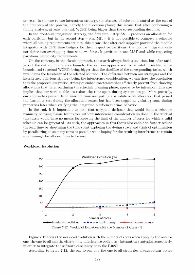
process. In the one-to-one integration strategy, the absence of solution is stated at the end ofthe first step of the process, namely the allocation phase; this means that after performing atiming analysis, at least one task WCRT being bigger than the corresponding deadline.
In the one-to-all integration strategy, the first step – step AS1 – produces an allocation foreach partition, but in the second step – step MI1 – it is not possible to compute a schedulewhere all timing requirements are met; this means that after each supplier provided the moduleintegrator with CPU time budgets for their respective partitions, the module integrator can-not define non-overlapping time windows for each partition in one MAF and while respectingpartitions periodicity requirements.
On the contrary, in the classic approach, the search always finds a solution, but after anal-ysis of the output interference bounds, the solution appears not to be valid in reality: somebounds lead to actual WCRTs being bigger than the deadline of the corresponding tasks, whichinvalidates the feasibility of the selected solution. The difference between our strategies and theinterference-oblivious strategy being the interference consideration, we can draw the conclusionthat the proposed integration strategies embed constraints that efficiently prevent from choosingallocations that, later on during the schedule planning phase, appear to be infeasible. This alsoimplies that our work enables to reduce the time spent during system design. More precisely,our approaches prevent from waisting time readjusting a schedule or an allocation that passedthe feasibility test during the allocation search but has been tagged as violating some timingproperties later when verifying the integrated platform runtime behavior.
In the end, it is important to note that a system designer that would build a schedulemanually or using classic techniques without interference consideration as done in the work ofthis thesis would have no means for knowing the limit of the number of cores for which a validschedule can be generated. As such, the approaches in this thesis also enable to further reducethe lead time by shortening the time spent exploring the design space and trials of optimizationby parallelizing on as many cores as possible while hoping for the resulting interference to remainsmall enough for all deadlines to be met.
Workload Evolution
Figure 7.12: Workload Evolution with the Number of Cores (%)
Figure 7.12 shows the workload evolution with the number of cores when applying the one-to-one, the one-to-all and the classic – i.e. interference-oblivious – integration strategies respectivelyin order to integrate the software case study onto the P4080.
According to figure 7.12, the one-to-one and the one-to-all strategies always return better
188
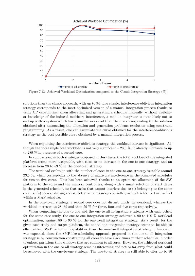
Figure 7.13: Achieved Workload Optimization compared to the Classic Integration Strategy (%)
solutions than the classic approach, with up to 94 The classic, interference-oblivious integrationstrategy corresponds to the most optimized version of a manual integration process thanks tousing CP capabilities: when allocating and generating a schedule manually, without visibilityor knowledge of the induced multicore interference, a module integrator is most likely not toend up with a system which has a smaller workload than the one corresponding to the solutionobtained after automating the allocation and generation problems resolution using constraintprogramming. As a result, one can assimilate the curve obtained for the interference-obliviousstrategy as the best possible curve obtained by a manual integration process.
When exploiting the interference-oblivious strategy, the workload increase is significant. Al-though the total single core workload is not very significant – 23,5 %, it already increases to upto 289 % in presence of a second core.
In comparison, in both strategies proposed in this thesis, the total workload of the integratedplatform seems more acceptable, with close to no increase in the one-to-one strategy, and anincrease from 28 to 59 % in the one-to-all strategy.
The workload evolution with the number of cores in the one-to-one strategy is stable around23,5 %, which corresponds to the absence of multicore interference in the computed schedulesfor two to five cores. This has been achieved thanks to an optimized allocation of the SWplatform to the cores and the memory controllers, along with a smart selection of start datesin the generated schedule, so that tasks that cannot interfere due to (i) belonging to the samecore, or (ii) to not sharing access to the same memory controller, are not scheduled in parallelwithin a MAF schedule.
In the one-to-all strategy, a second core does not disturb much the workload, whereas theworkload increases to 28, 39 and then 59 % for three, four and five cores respectively.
When comparing the one-to-one and the one-to-all integration strategies with each other,for the same case study, the one-to-one integration strategy achieved a 90 to 100 % workloadoptimization, against 80 to 90 % for the one-to-all integration strategy. As a result, for thegiven case study and target platform, the one-to-one integration strategy seems to be able tooffer better SWaP reduction capabilities than the one-to-all integration strategy. This resultwas expected, since the SMP-like scheduling approach proposed in the one-to-all integrationstrategy is by construction constraining all cores to have slack times in their schedules in orderto enforce partitions time windows that are common to all cores. However, the achieved workloadoptimization in the one-to-all strategy remains interesting and not so far away from what couldbe achieved with the one-to-one strategy. The one-to-all strategy is still able to offer up to 90
189

% workload reduction at least compared to a manual, interference-oblivious integration processfor up to DAL A IMA applications.
Interference and WCETs Upper-Bounds Evolution during the Integration
An interesting observation can be drawn from the previous results presented in this chapter.Despite the usage of static analysis techniques which are said to be overly pessimistic, theworkload increase in a multicore environment when compared to a single core one is significantin the classic strategy, whereas the one-to-one and one-to-all strategies do not suffer much fromthe increase of cores.
This is very encouraging for future work regarding further tightening of inter-core interfer-ence and WCET upper-bounds using static analyses. The interference models presented in thisthesis are high level. And the higher the level of abstraction, the more important the overestima-tion of WCET upper-bounds. However, despite relying on high level interference and schedulingmodels, (i) interesting workload reduction capabilities were observed, and (ii) schedules free ofinterference were always selected as a result of applying one of the two strategies proposed inthis thesis, for all configurations evaluated on a real target as described earlier in this chap-ter. Indeed, this is encouraging for the future development and improvement of static WCETanalysis techniques for multicore environments, static techniques often being qualified as toooverly pessimistic to be able to produce exploitable, pragmatic WCET upper-bounds that coulde exploited to generate a relevant schedule.
It is important to note that two interference-aware WCET analyses are conducted in eachintegration strategy proposed in this thesis, and although the resulting schedules are interference-free, the interference bounds computed during the first phases of each integration process werenot necessarily null.
When searching for a valid allocation, one must perform a feasibility analysis in order todetermine whether a given allocation configuration will later lead to the existence of at leastone valid schedule. The analysis is performed while no schedule exist yet, and must thereforerely on the worst possible scenario execution at runtime. On the other hand, in the presenceof a schedule, task instances executions are precisely identified on each core thanks to theirstart dates and WCET set as the time interval reserved to them respectively, several worst-case situations considered during the allocation verification can be ruled out from the scheduleverification.
For instance, let’s consider two tasks that share access to the same memory controller and areallocated to two different cores. During the allocation verification, one of the worst-case situationconsidered is the situation where both tasks are scheduled in parallel and therefore interfere witheach other at runtime. In such situation, they are seen as competing with each other in orderto access the main memory since they are allocated to the same memory controller. On theother hand, lets consider that these two tasks are never executed concurrently in the schedulegenerated later on during the schedule generation phase. During the schedule verification,one has knowledge about the fact that the tasks respective execution time intervals are neveroverlapping in time, and therefore that they do not interfere. As a consequence during theschedule verification, the two tasks will never be considered as causing interference delays toeach other, contrary to the allocation verification. Considering such a situation for every coupleof tasks allocated to the same memory controller but not the same core, one can draw theconclusion that the WCET upper-bounds computed as a result of the allocation verification willalways be bigger than the WCET upper-bounds computed as a result of the schedule verification.
To sum up, in all schedules reproduced on a real platform, interference delays have beenreduced to zero in the last steps of the one-to-one and the one-to-all integration strategies,although the corresponding delays computed as a result of the allocation verification were non-null. As a conclusion, it is safe to say that the optimization features introduced in the CPformulations presented in this thesis successfully managed to refine the computed interference
190

delays and WCET upper-bounds, from the early feasibility analysis performed in the first step ofthe integration process, to the schedulability analysis performed in the last step of the one-to-oneand one-to-all integration strategies respectively.
Although interference delays computed in feasibility analysis when allocating, were signifi-cant, the resulting, respective schedules are free of interference. As a result, one can draw theconclusion that as long as the allocation phase determines that there exists feasible schedules, nomatter the corresponding interference bounds. Since the generated schedule will always exhibitas less parallel execution of potentially interfering tasks as possible, the schedule will be theresult of a minimization of inter-core interference as much as possible.
This is undeniably an advantage of the proposed integration strategies. However, it is alsoa double edged quality. In fact, as schedules are generated only with the condition that theallocation phase found feasible configurations based on the timing analysis proposed in thisthesis, if that analysis produces too pessimistic WCRT upper-bounds, then there is a risk that theresult of the allocation verification is the absence of solution in the first steps of the integrationprocess, long before the step where schedules are generated.
Evolution of the CP Complexity
Tables 7.14 and 7.15 present the evolution of the number of variables and constraints of theCP formulation for the allocation and schedule generation CPs respectively with the number ofcores.
For the allocation CP problems, the number of variables and constraints increase with thenumber of cores; regarding the schedule generation CPs, they remain respectively constantindependently form the number fo cores. Every increase of variables and constraints is linearwith a small slope, except for the allocation CP in the one-to-all integration strategy. This is inline with the experimentations, where the allocation search has been the one taking the longesttime before finding at least one solution.
On the other hand in the one-to-all strategy, one has to keep in mind that for the sake ofsimplifying this thesis experimentation, we solved the allocation problem for all partitions alto-gether in one allocation CP: i.e. one solving process is launched in order to find an allocationto all nine partitions and their twenty-nine tasks in total. If used on an operational system,the allocation search would be performed on each partition separately: i.e there would be onesolving process launched per partition, each process trying to find an allocation for the three orfour tasks of each partition. The latter situation is likely to move from an exponential growthof the number of constraints, to a linear increase with a small slope similarly to all other CPs.
In general, the allocation and the schedule generation problems being NP-hard resolutionproblems, it is very interesting to note that we manage to escape the exponential complexityexplosion for all CP except the one-to-all allocation search CP. In an actual implementationof one of the two strategies, in the context of a real industrial system, one can easily imagineoneself reusing the proposed CP formulations, as each finds more than one solution in less thanthree minutes.
Figure 7.14: Evolution of the Number of Variables and Constraints for the Allocation Search
191
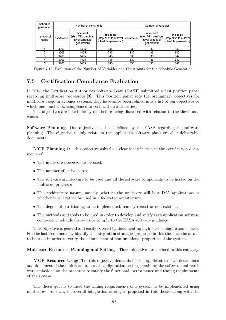
Figure 7.15: Evolution of the Number of Variables and Constraints for the Schedule Generation
7.5 Certification Compliance Evaluation
In 2014, the Certification Authorities Software Team (CAST) submitted a first position paperregarding multi-core processors [3]. This position paper sets the preliminary objectives formulticore usage in avionics systems; they have since been refined into a list of ten objectives towhich one must show compliance to certification authorities.
The objectives are listed one by one before being discussed with relation to the thesis out-comes.
Software Planning One objective has been defined by the EASA regarding the softwareplanning. The objective mainly relate to the applicant’s software plans or other deliverabledocuments.
MCP Planning 1: this objective asks for a clear identification in the certification docu-ments of:
• The multicore processor to be used;
• The number of active cores;
• The software architecture to be used and all the software components to be hosted on themulticore processor;
• The architecture nature, namely, whether the multicore will host IMA applications orwhether it will rather be used in a federated architecture;
• The degree of partitioning to be implemented, namely robust or non existent;
• The methods and tools to be used in order to develop and verify each application softwarecomponent individually so as to comply to the EASA software guidance.
This objective is general and easily covered by documenting high level configuration choices.For the last item, one may identify the integration strategies proposed in this thesis as the meansto be used in order to verify the enforcement of non-functional properties of the system.
Multicore Resources Planning and Setting Three objectives are defined in this category.
MCP Resource Usage 1: this objective demands for the applicant to have determinedand documented the multicore processor configuration settings enabling the software and hard-ware embedded on the processor to satisfy the functional, performance and timing requirementsof the system.
The thesis goal is to meet the timing requirements of a system to be implemented usingmulticores. As such, the overall integration strategies proposed in this thesis, along with the
192
corresponding data and parameters values resulting from each step inside each integration strat-egy respectively, fulfill this objective.
MCP Resource Usage 2: this objective asks for the applicant to have planned, devel-oper, documented, and verified a means that ensures an appropriate means of mitigation in theevent of any of the critical configuration settings of the multicore processor being inadvertentlyaltered.
This objective does not fall into the scope of this thesis, which is focused on non-functionalaspects of a multicore-based system rather than ensuring robustness to unexpected alterationsof the multicore platform.
MCP Planning 2: this objective requires out of the applicant that the plans and docu-ments forwarded to certification authorities:
• Provide a high-level description of how shared resources in the multicore platform will beused and how the applicant intend to allocate and verify their usage;
• Identify any hardware dynamic feature.
While the second bullet is out of the scope of this thesis, the first bullet is covered by theschedule generated as output of the strategies proposed in this thesis.
Interference Channels and Resource Usage Two objectives directly relate to interferencedue to shared resources.
MCP Resource Usage 3: this objective covers the identification of interference channelsable to potentially affect software applications at runtime. In particular, it is requested out ofthe applicant to handle any interference channel at any time during system design, and to per-form an interference analysis whenever deemed mandatory by the safety analysis, in order tomeet this objective.
This thesis takes into account interference in multicores. To do so, it relies on the prioridentification by the applicant of interference channels according to the usage they intend to doof the multicore platform. In the assumptions and the current state of the thesis, the only inter-ference channels identified are the main memory and the interconnect. No I/O or shared cachelevels are considered. In this configuration, an interference analysis is proposed, as requestedout of objective MCP Resource Usage 3. To show compliance to this objective when morethan these two interference channels can be identified (for instance, shared cache levels that theapplicant intends to exploit at runtime), one must also update the thesis contributions in orderto take them into account in the interference analysis.
MCP Resource Usage 4: this objective requests from the applicant to have allocatedthe resources of the multicore processor to the software applications, and verify that the de-mands for the resources do not exceed the available resources at runtime.
The thesis being focused on safe WCET upper-bounding, and embracing WCET upper-bounding annalysis in the allocation and schedule generation process, it is safe to say that thethesis outcomes comply to objective MCP Resource Usage 4.
Software Verification This section contains two objectives.
193

MCP Software 1: this objective asks for the applicant to verify that the software compo-nents function correctly and has sufficient time to complete their execution when all the hostedsoftware is executing in the intended final configuration.
While the functional correctness of software to be embedded on a multicore is out of thescope of this thesis, guaranteeing that each software application has sufficient time to completeits execution at runtime is covered by construction of the schedule in both integration strategiesproposed in this thesis.
MCP Software 2: this objective covers mandatory testing activities related to data andcontrol coupling between the applications hosted on different cores. As such, it is out of thescope of this thesis.
Error Detection and Handling, and Safety Nets Error detection and handling is coveredby one objective.
MCP Error Handling 1: this objective specifies that the effect of failures that can occurhave been identified, implemented and verified for the mulciore platform to be used. The corre-sponding means to detect and handle these failures in a fail safe manner must also be providedby the applicant.
Error detection and recovery is out of the scope of this thesis.
Reporting of Compliance with the Objectives of this Document
MCP Accomplishment Summary 1: this final objective mentions that the applicantmust explicitly demonstrate how the are complying to each of the previously mentioned objec-tives in the deliverables to be forwarded to certification authorities for approval.
This objective is general in the sense that it asks for argumentation and traceability of theobjectives enforcement. As such, regarding the scope of the thesis and the related objectives, theproposed contributions help an applicant to show compliance to objective MCP Accomplishment Summary 1,for instance by displaying how every activity in the integration process is conducted, and byproviding detailed information on the way allocations and schedules are configured.
7.6 Discussions
In this section we review the relevance of the evaluation tests with regards to the real targetplatform and test environment. In particular, we mention the limitations encountered duringthe evaluation phase, due to the necessity to stick to assumptions of the proposed contributions.We also discuss about the shortcomings that occurred during the tests environment setup andwhich are due to unexpected difficulties.
Conclusions of the Evaluation
When applying the one-to-one or the one-to-all integration strategy on a software case study anda real multicore platform with an avionics RTOS, results have shown the absence of deadlinemiss at runtime after a significant observation period. As such, the evaluation results of thisthesis enabled an empirical validation of the safeness of the produced WCET bounds, the timinganalysis and in general, the allocation and schedule generation processes.
194

As mentioned earlier in this chapter, the exact pessimism of the produced WCET upper-bounds cannot be known for certainty. As such, the difference observed between computedWCETs and maximum measured ETs consist in the maximum possible pessimism value. Ac-cording to the tests presented in this chapter, the difference between computed WCETs andmaximum measured ETs remained stable around 95% in both strategies and with a numberof cores from two to five, among which approximately 88 - 89 % is brought by the single-coremaximum execution duration upper-bound, and the other 6 - 7 % is due to the rest of theresponse time computational model proposed in this thesis. Knowing the rumor has it thatindustries are considering adding a 200 % margin to measured maximum ETs when runningon multicores, such results are promising for future time critical systems since: (i) it remainssmaller than the envisaged margin, and (ii) it is based on statically computed – therefore safe– WCET upper-bounds, which are thus reliable upper-bounds contrary to measurement-basedWCETs. In the future, more refined single-core analysis techniques may even help curb the 89% obtained in the evaluation tests.
To sum up, the evaluation results showed the safeness of the produced WCET bounds, andthe reliability of the generated schedules where every deadline is met at every MAF at runtime.This holds for both integration strategies. In addition to be based on a reliable timing analysis,each strategy proposed in this thesis can be used depending on the considered software platform.The one-to-all integration strategy is relevant for up to DAL A legacy IMA software, since eachapplication can be analyzed separately from each other, and it enforces a robust time and spacepartitioning as required out of IMA systems. On the other hand, the one-to-one integrationstrategy fits up to DAL C IMA applications for which the necessity of a robust partitioninghas not be stated. It can also be used to integrate multi-partition DAL A applications, i.e.systems where the considered multicore is exclusively running software corresponding to thatonly application. Finally, the one-to-one strategy can also be used for non IMA software, forexample to port software that was, as of today, integrated according to a federated architecture.
Implementation with Regards to the Assumptions
This subsection discusses the limitations linked to the way we matched this thesis assumptionswith the real environment of the evaluation platform.
The timing analysis proposed in this thesis takes into account one cache level only. On theother hand, the multicore chosen for the evaluation of this thesis presents a three-level cachehierarchy. As such, before launching any test, we deactivated the L2 and L3 caches availableon the processor in order to match the assumptions of this thesis when performing the testsdescribed in section 7.3.
In addition, the preliminary analysis for the extraction of single-core parameters Ci and Hi
for each task τi has been done with aiT [2]. Such an analysis requires a model of the targetprocessor. However, the target processor is not a single-core processor, and as such, no architec-tural model exists for static code level WCET analysis. As a workaround, we used the model ofa similar core, the MPC7448C, instead of the model of the P4080. Although the two architec-tures are similar since they present several features in common, such a workaround raises thequestion of the relevance of the single-core analysis with respect of the accuracy of the multicorearchitectural model exploited.
Finally, the worst-case overhead of a context switch is unknown since the detail of oper-ations performed at runtime during a context switch are hardware-dependent, and representinformation that is usually undisclosed to the public. As such, the value of CSW chosen for theevaluation tests relied on a couple of preliminary runs on the target platform in order to derivean upper-bound of all observed context switch durations.
195
Shortcomings
This subsection discusses the shortcoming encountered during the evaluation tests. This doesnot cover limitations due to the assumptions of this thesis, but rather unexpected difficultiesoccurring during the tests phase, and the limitations of the available test means.
This thesis is focused on the safe upper-bounding of inter-core interference that can occurat runtime, in advance at design time. As such, an important activity of the evaluation on areal target is the measurement of actual inter-core interference experienced by tasks at runtime.To do so, a probe is required. However, no such probe has been made available for this thesisevaluation purposes until the last weeks of the PhD. This represents one of the main limitationsof the thesis tests, since it prevented precise interference measurement through detailed analysisof runtime traces.
In order to be used, the probe has to be configured for the target hardware platform it is goingto snoop on and extract execution traces information. In particular, additional configurationsspecific to the exploited RTOS must be performed, in order to be able to distinguish whichexecution traces information corresponds to which task and partition at runtime. As such,configuring the probe requires some guidance from both the probe and the RTOS vendors atleast in order for all configuration steps to be performed accordingly prior to the tests.
The absence of probe did not enable the test setup to be able to extract interference latenciesexperienced by tasks. The beginning and end of tasks could be traced thanks to VxWorks6533.1 System Viewer [14], but no details on the amount of time in each execution corresponded tosome interference. On the other hand with a probe, it would have been interesting to observethe evolution of multicore interference with the number of cores and the memory usage intensityon the target platform.
Another shortcoming encountered during the tests setup were difficulties related to config-uring the target platform. Besides the usual amount of time spent for first manipulations ofthe platforms and training, additional time has been spent trying to find workarounds to someunexpected shortcomings.
For instance, an interesting experimentation of the thesis would have been to configure adifferent CPU clock for each core used in the P4080. To do so, beside understanding of thecomplex clocking system of the P4080 evaluation board, one would have to define a new boardsupport package for the RTOS with the updated CPU clocks frequencies. Indeed, it is currentlynot possible to easily edit the value of a core clock, as it is the output of a PLL involving aplatform clock, a core cluster clock et finally, a clock per core. A limited set of values can bepossible according to the platform datasheet, and one would also have to check by themselvesthat the values chosen for each intermediary clock is valid according to the values given in thedatasheet. To sum up, the complexity of the clocking system and the representation of sucha system in the platform and RTOS respective configuration frameworks made it impossiblewithin the time line of the thesis to experiment with different CPU clock frequencies.
Another shortcoming was the fact that tasks scheduling policy could not be changed to”user-defined”. This had an impact on the enforcement of the schedules computed as outputsof the corresponding integration strategy implemented. In fact, the task-level scheduling policywas fixed priority preemptive. Static schedules can be defined at partition level, but not at tasklevel. In order to still be able to enforce a static schedule at task-level, a non-negligible amountof time has been dedicated to finding a workaround approach, which was the following. In theRTOS development framework, we defined one partition per task, so that the start and durationspecified for each time window of that partition would correspond respectively to the start ofthe corresponding task instance and its associated WCET. This lead to other concerns, such asensuring there was enough memory space to store the context of each partition for instance.
Finally, the evaluation of the integration strategies proposed in this thesis required some
196
software case study. The case study must be representative of a legacy IMA software as canbe found in current IMA systems. However, any software produced for aircraft systems isconsidered confidential, and access to it is therefore restricted and carefully traced. As such,it was not possible to get actual legacy IMA software, let alone information on classic non-functional properties in general in current IMA software. Without such information, a nonnegligible amount of time has been dedicated to the specification and development of a casestudy representing an IMA software platform.
The resulting software has then been exploited during the evaluation phase for the tests torepresent a proof of concept, and hopefully convincing of the relevance of exploiting the thesisoutcomes in future aircraft systems. In order to do so, an important point has been made ingenerating a case study that was interesting enough in both the one-to-one and the one-to-allintegration strategies; indeed, it was important to have a case study for which solutions ofallocation and scheduling existed for more than just two cores, in both strategies, for the resultsto be interesting in terms of feedback of the thesis contributions.
However, it is a known problem of the real-time community that the software case studygeneration procedure can bias the results of a given schedulability analysis [30]. As such, the im-plemented case study generation approach presented earlier in this chapter cannot be exploitedfor evaluating the schedulability ratio as is usually done when evaluating a new scheduling al-gorithm. To do so would have required to spent more time on the unbiased generation of casestudies as proposed by Bini and Buttazzo [30]. However, the IMA architecture imposing a sec-ond level of scheduling, the work of Bini and Buttazzo cannot be exploited in the evaluationof this thesis, which therefore would have lead to further time spent on how to derive an IMAversion of the unbiased case study generation process proposed in [30].
Eventually, because of the amount of time spent designing a case study interesting enoughin both strategies for the evaluation to be interesting, no intra- and/or inter-partition commu-nications have been implemented.
7.7 Summary
This chapter presented the evaluation of the work presented in this thesis. The implementationof the test environment was presented, and we explained how we constructed a software casestudy for the purposes of the thesis evaluation. The tests performed were then presented, andthe corresponding results commented. In addition, the outcomes of the PhD was assessed withregards to certification compliance, and its applicability to industrial, real systems. Finally,a ”Discussions” section summarized the shortcomings of the evaluation phase, with a clearidentification of the limitations due to matching the test environment to the thesis assumptions,or to unexpected shortcomings occuring during the environment setup.
197

198
Chapter 8
Summary and Perspectives
8.1 Summary
This thesis addressed the challenges faced when considering the usage of multicore COTS plat-forms in future avionics systems embedding IMA applications. These challenges have beendiscussed in the context of an industrial usage, with strong certification constraints.
Motivated by the drawbacks of related works, the focus of this thesis is on the minimization ofcost, lead time and adaptation from current engineering and industrialization processes involvedin avionics systems design cycle. Indeed, the state of the art related to multicores and hard-realtime systems always implied either:
• Proposing custom hardware designs which implied high costs for aircraft manufacturers;
• Redesigning IMA legacy software in order to be parallelized on the cores of a multicoresystem, which implied having found a multicore-adequate methodology to do so, alongwith high efforts of adaptation from suppliers but also engineers responsible for gatheringall necessary information to convince certification authorities of the soundness and safetyof the corresponding new design process;
• Approaches not suited to the IMA concept, which therefore implied getting rid of the IMAconcepts.
The objectives of the thesis were the following:
• Minimize as much as possible changes to the current industrialization process for IMAsystems implied by the proposed contributions;
• Focus on hardware-independent approaches so that it is not specific to one multicore chipor manufacturer;
• Be compliant to current certification requirements and enforce the IMA, robust partition-ing and incremental verification concepts as much as possible.
Based on these objectives, the so-called one-to-one and one-to-all integration strategies, alongwith the associated WCET, feasibility and schedulability analyses have been developed.
The one-to-all integration strategy is based on a static SMP-like approach where at runtimeonly one application is scheduled on all cores of a multicore platform. The entire multicoreplatform is seen as one CPIOM (Core Processing Input/Output Module). Scheduling only oneapplication on all cores at runtime preserves the concept of robust partitioning, and therefore en-ables the strategy to remain compatible with strong certification requirements for IMA systems.The one-to-all strategy can be used for up to DAL A IMA applications.
The one-to-one integration strategy relies on a static AMP approach where each core isconsidered as a separate CPIOM at runtime. The one-to-one integration strategy enables to
199
achieve maximum SWaP reduction using our analysis techniques. However, the price to pay forsuch optimized systems is the absence of a strong time partitioning in the resulting system. Asa consequence, this strategy can be applied for non-IMA software, or in the context of multi-partition IMA applications, as long as all partitions allocated to the multicore platform belongto the same application.
To cover the verification of the system runtime behavior, both strategies embrace: (i) afeasibility analysis exploited during the allocation configuration phase, and (ii) a schedulabilityanalysis exploited during schedule configuration. The feasibility analysis is based on a derivationof the response time analysis to fit IMA architectures and multicore platforms. An interferencemodel has been proposed in order to produce a safe upper-bound of inter-task interferencedelays suffered at runtime in the worst-case situation by each task. The schedulability analysisreuses the interference model, along with the knowledge of the other cores schedules in orderto compute WCET upper-bounds for each task instance in one hyperperiod and verify that allcorresponding deadlines and non-functional requirements such as precedences are met in thecomputed schedule.
Finally, all steps of each integration strategy are expressed in the form of CP (ConstraintProgramming) problems, in order to enable the automation of the allocation, schedule generationand timing verification activities. Besides automation, exploiting CP techniques also enables tosave time and effort during the system design cycle. It also enables to insert optimization fea-tures via objective functions in order to smarten the configuration selection, which would havebeen very difficult to impossible to do manually.
The outcomes of the thesis have been evaluated on a COTS multicore platform that hasbeen considered for usage in avionics systems at its apparition, the NXP P4080 [9]. CPs havebeen implemented using IBM ILOG CP Optimizer [6]. The software aiT Analyzer [2] has beenused for performing single-core analysis, and Wind River VxWorks653 Multicore Edition RTOS[14] has been used in order to enforce schedules as specified in the output of the correspondingCP in each strategy.
The evaluation of both strategies revealed their soundness since no deadline missed has beendetected after observation of the system runtime behavior for several MAFs (MAjor Frames)and in various configurations.
The design optimization gain when using CP has been observed when comparing the outcomeof the one-to-one and one-to-all integration strategies with the classic, interference-oblivious allo-cation and scheduling CP problem. In particular, the experimentations have shown the efficiencyof the proposed approach. Each CP is solved within seconds, compared to days or weeks whenthe allocation and schedule generation are done manually. As such, our approach brings timeand effort gains when designing a system, without overlooking certification requirements thanksto safe timing behavior verification. In addition, using our approach suppresses the risk of latedetection of non-valid configurations. It is also easier for system designers to try different con-figurations, the valid and invalid ones clearly and rapidly being exhibited by the CP. Eventually,another novelty brought to system designers by our approach is the gain of visibility over theimpact of interference and resource usage intensity on the existence of valid schedules. The in-tegration process is now more flexible, as the gain of time and effort gives more room to systemdesigners to perform extra verification, try new combinations of allocations and further SWaPreduction, etc.
To sum up, the objectives towards certification-compliant multicore-based IMA industrialintegration process has been achieved. Secondary objectives of design optimization and time-to-market reduction have been achieved as well through the exploitation of CP techniques toexpress the problem at hand.
In addition to the functional aspects of the contributions of this thesis, the generality ofthe proposed approaches has been verified. First, one may notice the independence of the
200
strategies from the exploited hardware platform and RTOS. Second, it is possible to modifythe interference models implemented in the WCET analysis in order to exploit other state ofthe art interference analysis models instead. This is allowed both by the composability of theresponse time analysis, the safety-net mechanism relying on HM capabilities to handle anomaliesas faults, and the mathematical representation thanks to CP techniques.
Finally, both the one-to-one and the one-to-all integration strategies rely on a methodologyand timing analysis metrics that are made available in this thesis. In particular, the one-to-all integration strategy also respects current certification requirements that are mandatory foracceptance by certification authorities. As such, this strategy can be immediately exploited inan industrial process as a basis of a future multicore engineering process.
8.2 Conclusions
Models Optimization to Avoid State Space Explosion
Boolean Matrices instead of Vectors of Integers. As presented earlier in this chapter, inorder to represent the allocation of tasks and partitions to cores and memory controllers, booleanmatrices are chosen instead of vectors of integers (a and p2mc in the one-to-one integrationstrategy, na and t2mc in the one-to-all integration strategy). Vectors of integers could havebeen used instead, the ith value in the respective vector corresponding to the index of theallocated core or memory controller.
The justification of such a choice is the convenience of using boolean matrices when expressingsome of the constraints of the respective CPs. In fact in such constraints, the correspondingequations use sums in which only the designated elements are non null. If vectors of integerswere used instead, the sums would contain a condition on the corresponding integers in orderto filter the elements that should be evaluated in the sum.
For example for the core allocation in the one-to-one integration strategy, if a vector wasused instead of the boolean matrix a, the vector would be of size NP , and each element of thevector would be an integer corresponding to the index of the core the corresponding partitionis allocated to. The same changes would be true for the memory path allocation.
Such changes would then reflect on the complexity of equations of the allocation and schedulegeneration CPs defined in this thesis. Indeed, an example illustrating the convenience broughtby boolean matrices instead of vectors or integers for the allocation matrices can be foundwhen expressing equations reasoning at partition level – i.e. for each partition – but focusingon task-level information (for instance, tasks of a partition that are responsible for messagesending/writing actions) and/or allocation-specific information (for instance, memory controllersallocated to a given task allocated to a given core of a given partition).
With boolean matrices – i.e. terms equal to one if a given condition applies to them, and zerootherwise – one can express one equation for all partitions and tasks inside them respectively,by using sums, as will be done in the next chapters. The boolean elements of the matricescorresponding to tasks to which the condition does not apply will be equal to zero by definitionof these matrices, therefore enabling an automatic selection of all other tasks to which thecondition actually does apply.
In contrast, with integer vectors instead of boolean matrices, the same relation may corre-spond to a more complicated equation. In order to retrieve the same information, several ”foreach .. such that” nested loops are likely to be necessary.
Some ”for each” conditions may be necessary with boolean matrices as well; however, havingboolean matrices representing instead of vectors truly helps reduce the complexity of the CP tobe solved, but also save time during the CP solving process and therefore, the system time-to-market.
Another example is the computation of the cores MAF in the one-to-one integration strategy.For each core p, MAFp is defined in equation (4.19) as the maximum value of the periods of
201
the partitions allocated to core p. To do so, the selection of partitions is done using the apiterm multiplied by the corresponding partition period Pi, consequently Pi’s value if πi is notallocated to core p, and therefore ruling it out of the choice of the maximum value. If an integervector pcorealloc1, ..coreallocNP q was used instead of the boolean matrix a, excluding partitionsof other cores would have been done by using the following equation instead of equation (4.19):
@p P r1, NCs,MAFp “ maxπiPP〉
corealloci“p
pPiq (8.1)
In the allocation CP, corealloci would have been an unknown variable. As such, MAFpwould be expressed using a ”max” relation, conditioned by variables of the corresponding CP.
However, it is forbidden to define a sum depending on a variable even in such intermediaryexpressions. This is the case even in ILOG IBM CP Optimizer [6] which is, to our knowledge, cur-rently one of the most powerful CP solver on the market and which is usually capable of allowingmore flexibility in the definition of a CP formulation using intermediary expressions dependingon the CP variables. Similarly to MAFp, all other parameters which expression depends on theallocation would have to be defined as variables of the CP, leading to an unnecessarily complexCP to be solved.
Such an increase of complexity is deemed unnecessary since using matrix a is able to preventit easily. In addition, the allocation problem in general being NP-hard by itself already, theresulting CP is likely to easily become intractable. As such, defining a boolean matrix insteadof a vector of integers to model allocation variables optimizes the expressed CP problem so thatits complexity is minimized as much as possible.
Definition Domains and Representation of Time. One may notice that, in the schedulegeneration problem, no representation of time as an integer variable has been implemented. In-deed, it turns out that textbook formulations with time-indexed formulations are not well suitedfor tackling the problems of complexity arising in real-world applications. In fact, allocation andscheduling problems both ae NP-hard problems, even when treated separately. Explicitly rep-resenting time as in classic CP formulations implies defining an integer variable per CPU timeunit, so that the value of each time unit variable is constrained to be equal to the ID of the taskscheduled during that time instant.
Time instants must cover the entire MAF, which represents a significant number of additionalvariables for each CP. The time representation therefore significantly increases the complexity ofthe CP. The schedule generation CP may even become intractable, as has been observed whentime-indexed representation was implemented in the first versions of this thesis contributions.
As a conclusion, we did not keep the explicit time representation in the final version of thethesis outcomes, and we therefore chose not to represent time as discrete dates as usually donein classic CP scheduling problems. Instead, each start date – would that be for tasks executionsor partitions windows – is defined as an integer variable comprised in the interval v0;MAF w,since the schedule to be built corresponds to one MAF of the system. To ensure the selectedstart dates correspond to the corresponding core clock frequency, a constraint is expressed inthe corresponding CP to ensure only even multiples fo the clock frequency are selected.
Although intervals v0;MAF w are valid domain definitions for each task execution and par-tition window start date, they can be further refined by rejecting invalid values. For instancefor the task-level schedule generation, variable tOki corresponds to the activation date of thekth instance of τi. As such, by definition of task instances, the valid timing interval for tOki isactually vpk ´ 1qTi; kTiw, which is a smaller interval than v0;MAF w. Reducing timing intervalsfor all activation dates as in this example helps reducing the total solving time of the CP, sinceeach decision variable is defined with a smaller definition domain.
202
In practice however, index k corresponds to the frame number of the global schedule, andnot to the number of instances of τi. All tasks do not necessarily execute at each frame of theMAF. If τi does not run in the kth frame of the schedule, then tOki does not correspond to anactual instance of τi, and must therefore be set to zero in the corresponding scheduling CP, inorder to avoid reserving some CPU budget for anything other than actual execution instancesof tasks.
To be able to set to zero all activation dates tOki which do not correspond to actual taskexecutions to zero, the domain definition of activation dates must include the value zero. Assuch, one should define vpk ´ 1qTi; kTivXt0u as the definition domain of tOki . However, it maynot always be possible to define an intersection of intervals or sets as a domain definition inpractice, depending on the capabilities of the CP solvers currently available. An alternativecan be to define v0; kTiv as the definition domain of tOki instead. In that case, an additionalconstraint in the corresponding CP must be expressed in order to reject all values between 1and pk ´ 1qTi as invalid values for tOki . The expression of such a constraint will be given laterin chapter 6.
Path Allocation and Memory Space Allocation. In this thesis, we consider the softwareallocation phase to also include allocation to the memory paths and to the memory space.Both are linked and taken into account in this thesis, however we chose to represent only thepath allocation as variables of the allocation problem, and indirectly imply the memory spaceallocation from the path allocation.
In fact, the allocation of memory paths to partitions (resp. tasks), i.e. the action of decidingwhich partition (resp. task) is allowed to access which memory controller at runtime, impactsthe memory layout in non unified architectures. One must always verify that a given pathallocation is realistic, i.e. that the memory context of the partitions (resp. tasks) can indeed allbe allocated to the memory area addressed by the corresponding memory controller they haverespectively been allocated to.
Choosing to define the software to path allocation as variables of the allocation probleminstead of defining the software to memory areas allocation as variables, enables to significantlyreduce the number of implemented variables. Each memory page would have to be consideredas a component that could be allocated or not to any partition (resp. task), which would leadto much bigger matrices than t2mc and p2mc. Instead, one equation can be defined in theallocation problem as a constraint verifying that all memory contexts fit altogether in theirrespective memory areas. It is precisely the way it is done in this thesis, as will be explained inchapter 6.
Proposed Timing Analyses
Soundness of the Analyses. It is important to note that the implemented verification anal-yses are safe since they belong to the category of static analyses: the response time analysisis a sufficient condition of feasibility that bounds tasks WCRTs and WCETs, naming: (i) theworst-case execution duration of all code instructions of each task entry point, (ii) the time itspends being preempted and waiting to resume its execution; (iii) the time it spends waitingfor access to shared resources. No assumption is made on the memory requests arrival times, sothat the produced interference upper-bounds cover the worst-case scenario of arrival times byconsidering every request emitted on a core is the last one to be serviced at runtime. However,although this may lead to the production of safe WCET upper-bounds, the price to pay for itusually is significant pessimism in the produced bounds.
Modularity and Flexibility of the Proposed Interference Models and Timing Analy-ses. The timing analyses presented in this chapter enable to verify the validity of configurationchoices. One noticeable advantage of the equations representing the interference model is theirmodularity: it is possible to define an allocation and/or schedule search algorithm in which the
203

timing analysis is embedded, so that at design time, for each step of the design space explo-ration, an instantaneous answer can be obtained on the feasibility of the configuration underinvestigation. As such, as will be explained in chapter 6, the timing analysis proposed for allo-cation verification is exploited at the first stages of the integration as a sufficient condition forfeasibility to guide the software/hardware allocation choices. The timing analysis proposed forschedule verification is exploited once an allocation has been configured to guide the explorationphase during which a static scheduling table is built.
In addition, defining interference through functions dDRAM pq and dINT pq depending on thecorresponding tasks WCRTs is convenient for reusing the same interference functions for boththe allocation and the scheduling problems without requiring any significant model modification,despite the fact that tasks and partitions are represented throughout different parameters in theallocation and the scheduling problems. As such, the resulting timing analyses proposed in thisthesis can easily be transfered to any existing allocation and/or schedule generation framework.Moreover, if one wants to exploit hardware models for the main memory or the interconnectother than the ones presented in chapter 4, it is easy to update the timing analysis by modifyingimpacted equations accordingly. Such a characteristic is very convenient for controlling modelsobsolescence and regularly review state of the art multicore interference models.
Portability and Reuse. The two main hindrances to the extension of current static analysistechniques to multicore architectures are:
• The fact that multicore COTS embed complex components, which sometimes have non-deterministic arbitration policies;
• The fact that multicore COTS embed components which design features is undisclosed forIP protection purposes.
To our knowledge, as of today, every attempt at extending code-level WCET analysis fromsingle- to multicore environments lead to a state space explosion because of the complexity ofcurrent COTS architectures.
The timing analyses proposed in this thesis are static analysis techniques, and yet theydo not fall into the issue of state space explosion and intractability. Indeed, all necessaryparameters for interference bounding correspond to data that will always be made available toCOTS customers. In particular, the parameters for memory interference computation dependonly on standard DRAM timing parameters that can be found in the JEDEC standard, towhich all DRAM memories show compliance partly by disclosing their implementations of thecore parameters of JEDEC-compliant memories. As such, our analysis techniques are applicableto COTS since the necessary parameters for our analyses will always be disclosed.
In addition, our analysis techniques will not lead to state space explosion as can be experi-enced with static code analysis. The response time analysis abstracts a task by its schedulingparameters plus some extra parameters linked to its entry point (see task models presented inchapter 4). In contrast with code analysis, it does not rely on the exploration of execution traces,and as such, suffers no risk of state space explosion if performed in multicore environments.
Pessimism. As mentioned before in this thesis, the implemented analysis techniques use coarsegrain models, which saves time by easing the verification phase, but approximates timing boundsby upper values, which implies pessimistic bounds. The embedded pessimism is especially highfor the interference models which have been overly approximated to cope with undisclosedinformation in COTS, such as for the interconnect for example.
Another pessimism-inducing situation is the non-distinction between reads and writes re-quests, which have both different hardware actions, and thus lead to different serving latencies.However, as was also mentioned before, it is already a common habit of aerospace industriesto overestimate tasks WCETs by adding additional safety margins to the computed bounds,
204
even in single-core environments. As such, the pessimism displayed by our approach is not ahindrance to the reuse of our contributions by aerospace industries, which is the final goal of thisthesis: aerospace industries are likely to welcome the embedded pessimism as safety margins.Pessimism may reduce significantly the performance of a system statically configured, but allaerospace industries care about in the short term concerning multicores is determinism ratherthan performance.
Timing Anomalies and Applicability of our Work to COTS Architectures. As statedin the assumptions and presented in this chapter, tasks WCRTs and WCETs are computed asif the hardware architecture were anomaly-free. It is mostly not the case in current COTSmulticores. Although anomalies are not faulty events, we assume them to be handled as if theyactually were faulty events, e.g. by defining a specific recovery action to be undertaken in thecontext of health monitoring. The produced WCETs being safe upper-bounds except for theadvent of an anomaly occurring at runtime, the situation where a task tries to overrun its WCETat runtime could be considered as the occurrence of an anomaly.
To cope with anomalies and allow our WCET model to be valid despite the anomaly-freeassumption, we propose to enforce the computed WCET for each task at runtime by forcing anytask to hold the CPU for the exact amount of time represented by the computed WCET upper-bound. At the end of such a budget for a given task, we assume the task context to be switchedto the next task to be executed according to the static schedule defined or the scheduling policyenforced. In addition, we assume some monitoring mechanism to be able to detect whether atask execution was indeed finished or not, the latter case corresponding to the occurrence of ananomaly.
In such cases, a fault recovery action specifically defined to cope with anomalies is assumedto be undertaken by the OS, such as restarting the task or its partition window on anotherprocessing resource reserved for fault recovery. This mechanism corresponds to the safety netthat has been implemented by Jan Nowotsch in the context of his PhD thesis [122]. Such safetynet and health monitoring capabilities may therefore enable our work to remain applicable toCOTS architectures that are not timing anomaly-free.
Proposed Integration Strategies
Why two Strategies. The choice of providing two different strategies instead of one has beenmotivated by the different properties of the two propositions. While the one-to-all integrationstrategy respects all mandatory requirements of aerospace systems, the second integration strat-egy offers as much SWaP reduction as can be safely achievable (i.e. using DO-178 compliantanalysis techniques) for DAL A functions while using the timing analysis techniques proposedin this thesis. However, the one-to-one integration strategy does not comply with robust par-titioning requirements of DAL A functions, which means additional verification steps would beneeded, such as finding workarounds to robust partitioning for fault containment, or convincingcertification authorities and system designers of the validity of said workarounds for instance.Such additional steps are time and effort consuming, meaning that such a solution would notbe exploitable in the near future as the one-to-all integration strategy could be.
The one-to-one integration strategy is however still proposed as a contribution in this thesisbecause it may still be used for less critical functions for which it is not mandatory to forbidconcurrent accesses to shared resources at runtime, for instance provided that sufficient moni-toring recovery actions and specific protection mechanisms are used. For such functions, usingthe one-to-one integration strategy leads to optimized designs in which SWaP reduction hasbeen achieved as much as possible. For all other applications requiring to follow an incremen-tal certification acceptance process and requiring robust partitioning capabilities, the one-to-allintegration strategy must be used.
205

Legacy IMA Software versus Future IMA Software. As explained in chapter 2, theintegration process consists in discussions between application suppliers, system designers and amodule integrator. The proposed activities take place once each to-be-designed avionics functionhas been assigned to application suppliers, and once each application supplier has broken downthe to-be-designed function(s) it is responsible for into partitions and tasks. However, one maynotice that the integration strategy proposed in this thesis actually remain applicable if usedeither with legacy IMA software or software under development as well. Such a property isconvenient for aerospace industries, for which it means our one-to-all integration strategy canbe exploited for future systems as long as more optimized integration and/or coding techniquesable to fully benefit from parallelization capabilities are discovered. As such, we can say thatthe thesis succeeded in bringing a solution to the problem of implementing multicore-based IMAsystems in the nearest future possible.
8.3 Future Work
The integration strategies and the associated timing analyses provide a basis for the allocationand schedule generation verified in advance for IMA applications to be integrated into multicoreprocessors.
Some future work can be identified, for instance the experimentation of different optimizationcriterion for the schedule generation problems relative to each integration strategy. In fact,aside from the CPU workload, a common preoccupation of avionics system designers is thepartition context switches implied by a schedule, as they represent additional runtime overheadsunaccounted for in partitions time budgets. Partition switching is not free, and the time spentswitching contexts might result in partitions overrunning their allocated time budgets during oneMAF. As such, it might be interesting for industrial systems to optimize the schedule generatedby our CP in order to reduce the number of partition switches induced.
Unfortunately, the worst-case overhead of a partition switch is usually unknown [106, 75].There exists no model in the literature, since what is done during switch and how it is done isprocessor- and OS-dependent and usually never disclosed in detail due to IP protection. As such,it is not possible to safely bound context switch overheads. As a consequence, it is not possibleto define them as a constant added to partitions time windows either, since no upper-boundof context switching overheads can be proved to actually be an upper-bound, and then used inthe computation of tasks WCETs. This would correspond to an interesting continuation of thework presented in this thesis.
206

Chapter 9
Appendices
207
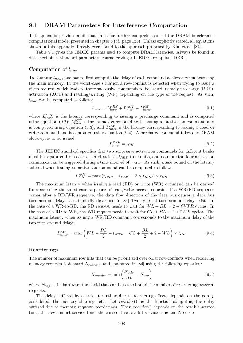
9.1 DRAM Parameters for Interference Computation
This appendix provides additional infos for further comprehension of the DRAM interferencecomputational model presented in chapter 5 (cf. page 123). Unless explicitly stated, all equationsshown in this appendix directly correspond to the approach proposed by Kim et al. [84].
Table 9.1 gives the JEDEC params used to compute DRAM latencies. Always be found indatasheet since standard parameters characterizing all JEDEC-compliant DRRs.
Computation of lmax
To compute lmax, one has to first compute the delay of each command achieved when accessingthe main memory. In the worst-case situation a row-conflict is detected when trying to issue agiven request, which leads to three successive commands to be issued, namely precharge (PRE),activation (ACT) and reading/writing (WR) depending on the type of the request. As such,lmax can be computed as follows:
lmax “ LPREinter ` LACTinter ` L
RWinter (9.1)
where LPREinter is the latency corresponding to issuing a precharge command and is computedusing equation (9.2); LACTinter is the latency corresponding to issuing an activation command andis computed using equation (9.3); and LRWinter is the latency corresponding to issuing a read orwrite command and is computed using equation (9.4). A precharge command takes one DRAMclock cycle to be issued:
LPREinter “ tCK (9.2)The JEDEC standard specifies that two successive activation commands for different banks
must be separated from each other of at least tRRD time units, and no more tan four activationcommands can be triggered during a time interval of tFAW . As such, a safe bound on the latencysuffered when issuing an activation command can be computed as follows:
LACTinter “ max ptRRD, tFAW ´ 3ˆ tRRDq ˆ tCK (9.3)
The maximum latency when issuing a read (RD) or write (WR) command can be derivedfrom assessing the worst-case sequence of read/write access requests. If a WR/RD sequencecomes after a RD/WR sequence, the data flow direction of the data bus causes a data busturn-around delay, as extendedly described in [84] Two types of turn-around delay exist. Inthe case of a WR-to-RD, the RD request needs to wait for WL ` BL “ 2 ` tWTR cycles. Inthe case of a RD-to-WR, the WR request needs to wait for CL ` BL “ 2 ` 2WL cycles. Themaximum latency when issuing a WR/RD command corresponds to the maximum delay of thetwo turn-around delays:
LRWinter “ maxˆ
WL`BL
2 ` tWTR, CL`BL
2 ` 2´WL
˙
ˆ tCK (9.4)
Reorderings
The number of maximum row hits that can be prioritized over older row-conflicts when reoderingmemory requests is denoted Nreorder, and computed in [84] using the following equation:
Nreorder “ minˆ
Ncols
BL, Ncap
˙
(9.5)
where Ncap is the hardware threshold that can be set to bound the number of re-ordering betweenrequests.
The delay suffered by a task at runtime due to reordering effects depends on the core pconsidered, the memory sharings, etc. Let reorderpq be the function computing the delaysuffered due to memory requests reorderings. Then reorderpq depends on the row-hit servicetime, the row-conflict service time, the consecutive row-hit service time and Nreorder.
208
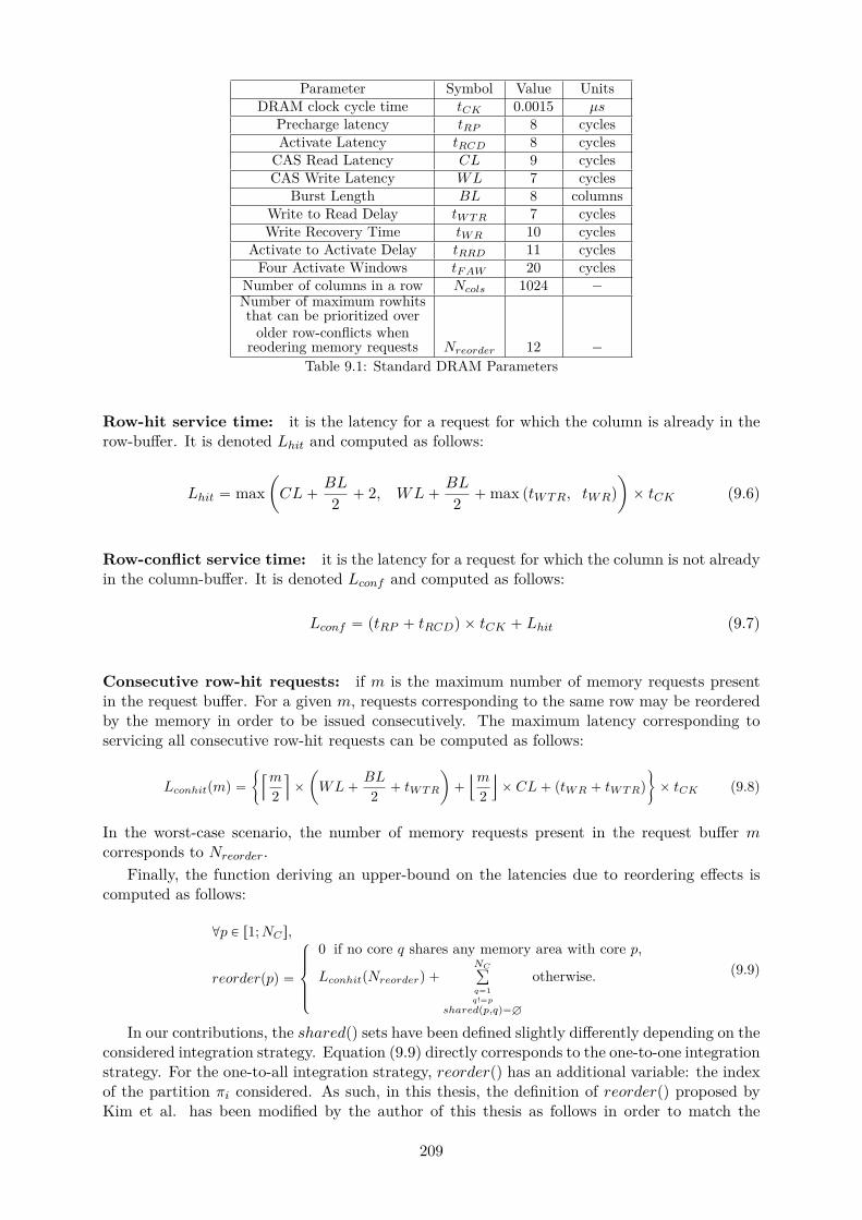
Parameter Symbol Value UnitsDRAM clock cycle time tCK 0.0015 µs
Precharge latency tRP 8 cyclesActivate Latency tRCD 8 cycles
CAS Read Latency CL 9 cyclesCAS Write Latency WL 7 cycles
Burst Length BL 8 columnsWrite to Read Delay tW T R 7 cyclesWrite Recovery Time tW R 10 cycles
Activate to Activate Delay tRRD 11 cyclesFour Activate Windows tF AW 20 cycles
Number of columns in a row Ncols 1024 ´
Number of maximum rowhitsthat can be prioritized over
older row-conflicts whenreodering memory requests Nreorder 12 ´
Table 9.1: Standard DRAM Parameters
Row-hit service time: it is the latency for a request for which the column is already in therow-buffer. It is denoted Lhit and computed as follows:
Lhit “ maxˆ
CL`BL
2 ` 2, WL`BL
2 `max ptWTR, tWRq
˙
ˆ tCK (9.6)
Row-conflict service time: it is the latency for a request for which the column is not alreadyin the column-buffer. It is denoted Lconf and computed as follows:
Lconf “ ptRP ` tRCDq ˆ tCK ` Lhit (9.7)
Consecutive row-hit requests: if m is the maximum number of memory requests presentin the request buffer. For a given m, requests corresponding to the same row may be reorderedby the memory in order to be issued consecutively. The maximum latency corresponding toservicing all consecutive row-hit requests can be computed as follows:
Lconhitpmq “
"
Qm
2
U
ˆ
ˆ
WL`BL
2 ` tW T R
˙
`
Ym
2
]
ˆ CL` ptW R ` tW T Rq
*
ˆ tCK (9.8)
In the worst-case scenario, the number of memory requests present in the request buffer mcorresponds to Nreorder.
Finally, the function deriving an upper-bound on the latencies due to reordering effects iscomputed as follows:
@p P r1;NCs,
reorderppq “
$
’
’
&
’
’
%
0 if no core q shares any memory area with core p,
LconhitpNreorderq `NCř
q“1q!“p
sharedpp,qq“H
otherwise. (9.9)
In our contributions, the sharedpq sets have been defined slightly differently depending on theconsidered integration strategy. Equation (9.9) directly corresponds to the one-to-one integrationstrategy. For the one-to-all integration strategy, reorderpq has an additional variable: the indexof the partition πi considered. As such, in this thesis, the definition of reorderpq proposed byKim et al. has been modified by the author of this thesis as follows in order to match the
209

one-to-all integration strategy:
@p P r1;NCs,@πi,
reorderpp, jq “
$
’
’
’
’
&
’
’
’
’
%
0 if no task of πi on another core than p shares anymemory area with core p,
LconhitpNreorderq `NCř
q“1q!“p
sharedpi,p,qq“H
otherwise.(9.10)
210
Bibliography
[1] ”ARINC 653 avionics application software standard interface”, 1996.
[2] aiT WCET Analyzers, AbsInt Angewandte Informatik GmbH.
[3] CAST-32, ”Multi-core Processors”, 2014.
[4] EASA Official Website: https://www.easa.europa.eu.
[5] Federal Aviation Authorities’ Official Website: http://www.faa.gov.
[6] IBM ILOG, Cplex CP Optimizer. Website: http://www-01.ibm.com/software/commerce/optimization/cplex-cp-optimizer/.
[7] Infineon Aurix Tricore Presentation. Website: http://www.infineon.com/cms/en/product/microcontroller/32-bit-tricore-tm-microcontroller/channel.html?channel=ff80808112ab681d0112ab6b64b50805.
[8] Joint Aviation Authorities’ Official Website: https://jaato.com.
[9] QorIQTM p4080 Communications Processor, NXP (ex Freescale), Product Brief.
[10] RTCA Radio Technical Commission for Aeronautics, ”Software Considerations in AirborneSystems and Equipment Certification” (DO178), 1992.
[11] SAE International, ”Aerospace Recommended Practice ARP4754 – Guidelines For Devel-opment Of Civil Aircraft and Systems”, issued 1996; published 2010.
[12] SAE International’s Official Website: http://www.sae.org.
[13] TACLEbench, TACLe Benchmark Suite – TACLe (Timing Analysis at Code Level) ICTCOST Action IC1202. Website: http://www.tacle.eu/index.php/activities/taclebench.
[14] Wind river VxWorks 653 3.0 Multi-Core Edition, Wind River Inc, Product Overview.
[15] Benny Akesson, Kees Goossens, and Markus Ringhofer. Predator: a predictable sdrammemory controller. In Proceedings of the 5th IEEE/ACM international conference onHardware/software codesign and system synthesis, pages 251–256. ACM, 2007.
[16] Ahmad Al Sheikh. Resource allocation in hard real-time avionic systems: scheduling androuting problems. PhD thesis, Toulouse, INSA, 2011.
[17] Ahmad Al Sheikh, Olivier Brun, and Pierre-Emmanuel Hladik. Partition Scheduling onan IMA Platform with Strict Periodicity and Communication Delays. In 18th Interna-tional Conference on Real-Time and Network Systems, pages 179–188, Toulouse, France,November 2010.
[18] Luis Almeida and Paulo Pedreiras. Scheduling within temporal partitions: response-timeanalysis and server design. In Proceedings of the 4th ACM international conference onEmbedded software, pages 95–103. ACM, 2004.
211
[19] Sebastian Altmeyer, Robert I. Davis, Leandro Soares Indrusiak, Claire Maiza, VincentNelis, and Jan Reineke. A generic and compositional framework for multicore responsetime analysis. In Proceedings of the 23rd International Conference on Real Time andNetworks Systems, RTNS 2015, Lille, France, November 4-6, 2015, pages 129–138, 2015.
[20] Sebastian Altmeyer, Roeland Douma, Will Lunniss, and Robert I Davis. Outstandingpaper: Evaluation of cache partitioning for hard real-time systems. In 2014 26th EuromicroConference on Real-Time Systems, pages 15–26. IEEE, 2014.
[21] James H Anderson, Sanjoy K Baruah, and Bjorn B Brandenburg. Multicore operating-system support for mixed criticality. Citeseer.
[22] James H Anderson, John M Calandrino, and UmaMaheswari C Devi. Real-time schedulingon multicore platforms. In 12th IEEE Real-Time and Embedded Technology and Applica-tions Symposium (RTAS’06), pages 179–190. IEEE, 2006.
[23] Nesrine Badache. Allocation temporelle de systemes avioniques modulaires embarques.PhD thesis, 2016.
[24] Andrea Baldovin, Alessandro Zovi, Geoffrey Nelissen, and Stefano Puri. The concertomethodology for model-based development of avionics software. In Ada-Europe Interna-tional Conference on Reliable Software Technologies, pages 131–145. Springer, 2015.
[25] Sanjoy Baruah and Bjorn Brandenburg. Multiprocessor feasibility analysis of recurrenttask systems with specified processor affinities. In Real-Time Systems Symposium (RTSS),2013 IEEE 34th, pages 160–169. IEEE, 2013.
[26] Sanjoy Baruah and Gerhard Fohler. Certification-cognizant time-triggered scheduling ofmixed-criticality systems. In Real-Time Systems Symposium (RTSS), 2011 IEEE 32nd,pages 3–12. IEEE, 2011.
[27] Sanjoy K Baruah, Alan Burns, and Robert I Davis. Response-time analysis for mixedcriticality systems. In Real-Time Systems Symposium (RTSS), 2011 IEEE 32nd, pages34–43. IEEE, 2011.
[28] Moris Behnam. Hierarchical real time scheduling and synchronization. 2008.
[29] Jingyi Bin, Sylvain Girbal, Daniel Gracia Perez, Arnaud Grasset, and Alain Merigot.Studying co-running avionic real-time applications on multi-core cots architectures. Em-bedded real time software and systems (ERTS’14), 2014.
[30] Enrico Bini and Giorgio C Buttazzo. Biasing effects in schedulability measures. In Real-Time Systems, 2004. ECRTS 2004. Proceedings. 16th Euromicro Conference on, pages196–203. IEEE, 2004.
[31] Konstantinos Bletsas and Stefan M Petters. Using nps-f for mixed-criticality multicoresystems. In 33rd IEEE Real-Time Systems Symposium, pages 36–36. ACM, 2012.
[32] Frederic Boniol, Hugues Casse, Eric Noulard, and Claire Pagetti. Deterministic execu-tion model on cots hardware. In International Conference on Architecture of ComputingSystems, pages 98–110. Springer, 2012.
[33] Frederic Boniol, Pierre-Emmanuel Hladik, Claire Pagetti, Frederic Aspro, and Victor Jegu.A framework for distributing real-time functions. In International Conference on FormalModeling and Analysis of Timed Systems, pages 155–169. Springer, 2008.
212
[34] Richard Bradford, Shana Fliginger, Rockwell Collins, Cedar Rapids, Sibin Mohan, RodolfoPellizzoni, Cheolgi Kim, Marco Caccamo, Lui Sha, et al. Exploring the design space of imasystem architectures. In Digital Avionics Systems Conference (DASC), 2010 IEEE/AIAA29th, pages 5–E. IEEE, 2010.
[35] Bach D Bui, Marco Caccamo, Lui Sha, and Joseph Martinez. Impact of cache partitioningon multi-tasking real time embedded systems. In 2008 14th IEEE International Conferenceon Embedded and Real-Time Computing Systems and Applications, pages 101–110. IEEE,2008.
[36] Paolo Burgio, Martino Ruggiero, Francesco Esposito, Mauro Marinoni, Giorgio Buttazzo,and Luca Benini. Adaptive tdma bus allocation and elastic scheduling: a unified approachfor enhancing robustness in multi-core rt systems. In Computer Design (ICCD), 2010IEEE International Conference on, pages 187–194. IEEE, 2010.
[37] Alan Burns and Rob Davis. Mixed criticality systems-a review. Department of ComputerScience, University of York, Tech. Rep, 2013.
[38] Thomas Carle, Dumitru Potop-Butucaru, Yves Sorel, and David Lesens. From dataflowspecification to multiprocessor partitioned time-triggered real-time implementation. Leib-niz Transactions on Embedded Systems, 2(2):01–1, 2015.
[39] Karam S Chatha and Ranga Vemuri. Magellan: multiway hardware-software partitioningand scheduling for latency minimization of hierarchical control-dataflow task graphs. InProceedings of the ninth international symposium on Hardware/software codesign, pages42–47. ACM, 2001.
[40] Sudipta Chattopadhyay, Lee Kee Chong, Abhik Roychoudhury, Timon Kelter, Peter Mar-wedel, and Heiko Falk. A unified wcet analysis framework for multicore platforms. ACMTransactions on Embedded Computing Systems (TECS), 13(4s):124, 2014.
[41] Sudipta Chattopadhyay, Abhik Roychoudhury, and Tulika Mitra. Modeling shared cacheand bus in multi-cores for timing analysis. In Proceedings of the 13th international work-shop on software & compilers for embedded systems, page 6. ACM, 2010.
[42] Micaiah Chisholm, Bryan C Ward, Namhoon Kim, and James H Anderson. Cache shar-ing and isolation tradeoffs in multicore mixed-criticality systems. In Real-Time SystemsSymposium, 2015 IEEE, pages 305–316. IEEE, 2015.
[43] Bekim Cilku, Alfons Crespo, Peter Puschner, Javier Coronel, and Salvador Peiro. A tdma-based arbitration scheme for mixed-criticality multicore platforms. In Event-based Control,Communication, and Signal Processing (EBCCSP), 2015 International Conference on,pages 1–6. IEEE, 2015.
[44] Mikel Cordovilla, Frederic Boniol, Julien Forget, Eric Noulard, and Claire Pagetti. De-veloping critical embedded systems on multicore architectures: the prelude-schedmcoretoolset. In 19th International Conference on Real-Time and Network Systems, 2011.
[45] Luis Alejandro Cortes, Petru Eles, and Zebo Peng. Quasi-static scheduling for real-timesystems with hard and soft tasks. In Proceedings of the conference on Design, automationand test in Europe-Volume 2, page 21176. IEEE Computer Society, 2004.
[46] Alfons Crespo, Ismael Ripoll, and Miguel Masmano. Partitioned embedded architec-ture based on hypervisor: The xtratum approach. In Dependable Computing Conference(EDCC), 2010 European, pages 67–72. IEEE, 2010.
213
[47] Dakshina Dasari, Bjorn Andersson, Vincent Nelis, Stefan M Petters, Arvind Easwaran,and Jinkyu Lee. Response time analysis of cots-based multicores considering the contentionon the shared memory bus. In 2011IEEE 10th International Conference on Trust, Securityand Privacy in Computing and Communications, pages 1068–1075. IEEE, 2011.
[48] Dakshina Dasari, Bjorn Andersson, Vincent Nelis, Stefan M Petters, Arvind Easwaran,and Jinkyu Lee. Response time analysis of cots-based multicores considering the contentionon the shared memory bus. In 2011IEEE 10th International Conference on Trust, Securityand Privacy in Computing and Communications, pages 1068–1075. IEEE, 2011.
[49] Dakshina Dasari, Bjorn Andersson, Vincent Nelis, Stefan M Petters, Arvind Easwaran,and Jinkyu Lee. Response time analysis of cots-based multicores considering the contentionon the shared memory bus. In Trust, Security and Privacy in Computing and Communica-tions (TrustCom), 2011 IEEE 10th International Conference on, pages 1068–1075. IEEE,2011.
[50] Dakshina Dasari, Vincent Nelis, and Bjorn Andersson. Wcet analysis considering con-tention on memory bus in cots-based multicores. In Emerging Technologies & FactoryAutomation (ETFA), 2011 IEEE 16th Conference on, pages 1–4. IEEE, 2011.
[51] Robert Davis, Tullio Vardanega, Jan Alexanderson, Vatrinet Francis, Pearce Mark, BrosterIan, Azkarate-Askasua Mikel, Franck Wartel, Liliana Cucu-Grosjean, Patte Mathieu, et al.Proxima: A probabilistic approach to the timing behaviour of mixed-criticality systems.Ada User Journal, 2:118–122, 2014.
[52] Robert I Davis and Alan Burns. Hierarchical fixed priority pre-emptive scheduling. In26th IEEE International Real-Time Systems Symposium (RTSS’05), pages 10–pp. IEEE,2005.
[53] Dionisio De Niz, Karthik Lakshmanan, and Ragunathan Rajkumar. On the scheduling ofmixed-criticality real-time task sets. In Real-Time Systems Symposium, 2009, RTSS 2009.30th IEEE, pages 291–300. IEEE, 2009.
[54] Dionisio de Niz and Linh TX Phan. Partitioned scheduling of multi-modal mixed-criticalityreal-time systems on multiprocessor platforms. In 2014 IEEE 19th Real-Time and Em-bedded Technology and Applications Symposium (RTAS), pages 111–122. IEEE, 2014.
[55] Zhong Deng and JW-S Liu. Scheduling real-time applications in an open environment.In Real-Time Systems Symposium, 1997. Proceedings., The 18th IEEE, pages 308–319.IEEE, 1997.
[56] Olivier Desenfans, Antonio Paolillo, Vladimir Svoboda, Ben Rodriguez, Joel Goossens,and Dragomir Milojevic. Design and implementation of a multi-core embedded real-timeoperating system kernel.
[57] Roeland J Douma, Sebastian Altmeyer, and Andy D Pimentel. Fast and precise cacheperformance estimation for out-of-order execution. In Proceedings of the 2015 Design, Au-tomation & Test in Europe Conference & Exhibition, pages 1132–1137. EDA Consortium,2015.
[58] Guy Durrieu, Madeleine Faugere, Sylvain Girbal, Daniel Gracia Perez, Claire Pagetti, andWolfgang Puffitsch. Predictable flight management system implementation on a multicoreprocessor. In Embedded Real Time Software (ERTS’14), 2014.
[59] Stephen A Edwards and Edward A Lee. The case for the precision timed (pret) machine.In Proceedings of the 44th annual Design Automation Conference, pages 264–265. ACM,2007.
214
[60] Friedrich Eisenbrand, Nicolai Hahnle, Martin Niemeier, Martin Skutella, Jose Verschae,and Andreas Wiese. Scheduling periodic tasks in a hard real-time environment. In Interna-tional Colloquium on Automata, Languages, and Programming, pages 299–311. Springer,2010.
[61] Cecilia Ekelin and Jan Jonsson. Solving embedded system scheduling problems usingconstraint programming. 2000.
[62] Xiang Feng and Aloysius K Mok. A model of hierarchical real-time virtual resources. InReal-Time Systems Symposium, 2002. RTSS 2002. 23rd IEEE, pages 26–35. IEEE, 2002.
[63] Christian Ferdinand, Reinhold Heckmann, Marc Langenbach, Florian Martin, MichaelSchmidt, Henrik Theiling, Stephan Thesing, and Reinhard Wilhelm. Reliable and precisewcet determination for a real-life processor. In International Workshop on EmbeddedSoftware, pages 469–485. Springer, 2001.
[64] Gabriel Fernandez, Jaume Abella, Eduardo Quinones, Christine Rochange, Tullio Var-danega, and Francisco J. Cazorla. Contention in multicore hardware shared resources:Understanding of the state of the art. In 14th International Workshop on Worst-CaseExecution Time Analysis, WCET 2014, July 8, 2014, Ulm, Germany, pages 31–42, 2014.
[65] Nathan Fisher, James H Anderson, and Sanjoy Baruah. Task partitioning upon memory-constrained multiprocessors. In 11th IEEE International Conference on Embedded andReal-Time Computing Systems and Applications (RTCSA’05), pages 416–421. IEEE, 2005.
[66] Rudolf Fuchsen. How to address certification for multi-core based ima platforms: Currentstatus and potential solutions. In Digital Avionics Systems Conference (DASC), 2010IEEE/AIAA 29th, pages 5–E. IEEE, 2010.
[67] Georgia Giannopoulou, Nikolay Stoimenov, Pengcheng Huang, and Lothar Thiele. Map-ping mixed-criticality applications on multi-core architectures. In Design, Automation &Test in Europe Conference & Exhibition, DATE 2014, Dresden, Germany, March 24-28,2014, pages 1–6, 2014.
[68] Sylvain Girbal, Daniel Gracia Perez, Jimmy Le Rhun, Madeleine Faugere, Claire Pagetti,and Guy Durrieu. A complete tool-chain for an interference-free deployment of avionicapplications on multi-core systems. In 2015 IEEE/AIAA 34th Digital Avionics SystemsConference (DASC), pages 1–13. IEEE, 2015.
[69] M Gonzalez Harbour, JJ Gutierrez Garcıa, JC Palencia Gutierrez, and JM Drake Moyano.Mast: Modeling and analysis suite for real time applications. In Real-Time Systems, 13thEuromicro Conference on, 2001., pages 125–134. IEEE, 2001.
[70] Dip Goswami, Martin Lukasiewycz, Reinhard Schneider, and Samarjit Chakraborty. Time-triggered implementations of mixed-criticality automotive software. In Proceedings of theConference on Design, Automation and Test in Europe, pages 1227–1232. EDA Consor-tium, 2012.
[71] Stefan Groesbrink, Luis Almeida, Mario de Sousa, and Stefan M Petters. Towards certi-fiable adaptive reservations for hypervisor-based virtualization. In 2014 IEEE 19th Real-Time and Embedded Technology and Applications Symposium (RTAS), pages 13–24. IEEE,2014.
[72] Stefan Groesbrink, Simon Oberthur, and Daniel Baldin. Architecture for adaptive re-source assignment to virtualized mixed-criticality real-time systems. ACM SIGBED Re-view, 10(1):18–23, 2013.
215

[73] Nan Guan, Martin Stigge, Wang Yi, and Ge Yu. Cache-aware scheduling and analysisfor multicores. In Proceedings of the seventh ACM international conference on Embeddedsoftware, pages 245–254. ACM, 2009.
[74] Arne Hamann, Rafik Henia, Razvan Racu, Marek Jersak, Kai Richter, and Rolf Ernst.Symta/s - symbolic timing analysis for systems, 2004.
[75] Sanghyun Han and Hyun-Wook Jin. Resource partitioning for integrated modular avionics:comparative study of implementation alternatives. Software: Practice and Experience,44(12):1441–1466, 2014.
[76] Damien Hardy and Isabelle Puaut. Wcet analysis of multi-level non-inclusive set-associative instruction caches. In Real-Time Systems Symposium, 2008, pages 456–466.IEEE, 2008.
[77] Mohamed Hassan and Hiren Patel. Criticality-and requirement-aware bus arbitration formulti-core mixed criticality systems. In 2016 IEEE Real-Time and Embedded Technologyand Applications Symposium (RTAS), pages 1–11. IEEE, 2016.
[78] Pierre-Emmanuel Hladik, Hadrien Cambazard, Anne-Marie Deplanche, and NarendraJussien. Solving allocation problems of hard real-time systems with dynamic constraintprogramming. In 14th International Conference on Real-Time and Network Systems(RTNS’06), pages 214–223, 2006.
[79] Pengcheng Huang, Georgia Giannopoulou, Rehan Ahmed, Davide B Bartolini, and LotharThiele. An isolation scheduling model for multicores. In Real-Time Systems Symposium,2015 IEEE, pages 141–152. IEEE, 2015.
[80] Xavier Jean. Hypervisor control of COTS multicores processors in order to enforce de-terminism for future avionics equipment. PhD thesis, PhD Thesis, Telecom ParisTech,2015.
[81] Mathai Joseph and Paritosh K. Pandya. Finding response times in a real-time system.Comput. J., 29(5):390–395, 1986.
[82] Owen R Kelly, Hakan Aydin, and Baoxian Zhao. On partitioned scheduling of fixed-priority mixed-criticality task sets. In 2011IEEE 10th International Conference on Trust,Security and Privacy in Computing and Communications, pages 1051–1059. IEEE, 2011.
[83] Omar Kermia and Yves Sorel. Schedulability analysis for non-preemptive tasks under strictperiodicity constraints. In The Fourteenth IEEE Internationl Conference on Embedded andReal-Time Computing Systems and Applications, RTCSA 2008, Kaohisung, Taiwan, 25-27August 2008, Proceedings, pages 25–32, 2008.
[84] Hyoseung Kim, Dionisio de Niz, Bjorn Andersson, Mark H. Klein, Onur Mutlu, and Ragu-nathan Rajkumar. Bounding memory interference delay in cots-based multi-core systems.In 20th IEEE Real-Time and Embedded Technology and Applications Symposium, RTAS2014, Berlin, Germany, April 15-17, 2014, pages 145–154, 2014.
[85] Hyoseung Kim, Arvind Kandhalu, and Ragunathan Rajkumar. A coordinated approachfor practical os-level cache management in multi-core real-time systems. In Real-TimeSystems (ECRTS), 2013 25th Euromicro Conference on, pages 80–89. IEEE, 2013.
[86] Hyoseung Kim, Arvind Kandhalu, and Ragunathan Rajkumar. A coordinated approachfor practical os-level cache management in multi-core real-time systems. In 2013 25thEuromicro Conference on Real-Time Systems, pages 80–89. IEEE, 2013.
216
[87] Jung-Eun Kim, Man-Ki Yoon, Sungjin Im, Richard Bradford, and Lui Sha. Multi-ima par-tition scheduling with synchronized solo-partitions for multi-core avionics systems. 2012.
[88] Yooseong Kim, David Broman, Jian Cai, and Aviral Shrivastaval. Wcet-aware dynamiccode management on scratchpads for software-managed multicores. In 2014 IEEE 19thReal-Time and Embedded Technology and Applications Symposium (RTAS), pages 179–188. IEEE, 2014.
[89] M.T. Kirsch. Technical Support to the National Highway Traffic Safety Administration(NHTSA) on the Reported Toyota Motor Corporation (TMC) Unintended Acceleration(UA) Investigation. DIANE Publishing.
[90] Ondrej Kotaba, Jan Nowotsch, Michael Paulitsch, Stefan M Petters, and Henrik Theil-ing. Multicore in real-time systems–temporal isolation challenges due to shared resources.In Workshop on Industry-Driven Approaches for Cost-effective Certification of Safety-Critical, Mixed-Criticality Systems, 2014.
[91] Angeliki Kritikakou, Christine Rochange, Madeleine Faugere, Claire Pagetti, MatthieuRoy, Sylvain Girbal, and Daniel Gracia Perez. Distributed run-time WCET controller forconcurrent critical tasks in mixed-critical systems. In 22nd International Conference onReal-Time Networks and Systems, RTNS ’14, Versaille, France, October 8-10, 2014, page139, 2014.
[92] NG Chetan Kumar, Sudhanshu Vyas, Ron K Cytron, Christopher D Gill, Joseph Zam-breno, and Phillip H Jones. Cache design for mixed criticality real-time systems. In 2014IEEE 32nd International Conference on Computer Design (ICCD), pages 513–516. IEEE,2014.
[93] Tei-Wei Kuo and Ching-Hui Li. A fixed-priority-driven open environment for real-timeapplications. In Real-Time Systems Symposium, 1999. Proceedings. The 20th IEEE, pages256–267. IEEE, 1999.
[94] Chang-Gun Lee, Hoosun Hahn, Yang-Min Seo, Sang Lyul Min, Rhan Ha, Seongsoo Hong,Chang Yun Park, Minsuk Lee, and Chong Sang Kim. Analysis of cache-related preemptiondelay in fixed-priority preemptive scheduling. IEEE transactions on computers, 47(6):700–713, 1998.
[95] Insup Lee, Joseph YT Leung, and Sang H Son. Handbook of real-time and embeddedsystems. CRC Press, 2007.
[96] Yann-Hang Lee, Daeyoung Kim, Mohamed Younis, Jeff Zhou, and James McElroy. Re-source scheduling in dependable integrated modular avionics. In Dependable Systems andNetworks, 2000. DSN 2000. Proceedings International Conference on, pages 14–23. IEEE,2000.
[97] Benjamin Lesage, Damien Hardy, and Isabelle Puaut. Wcet analysis of multi-level set-associative data caches. In OASIcs-OpenAccess Series in Informatics, volume 10. SchlossDagstuhl-Leibniz-Zentrum fur Informatik, 2009.
[98] Benjamin Lesage, Isabelle Puaut, and Andre Seznec. Preti: Partitioned real-time sharedcache for mixed-criticality real-time systems. In Proceedings of the 20th InternationalConference on Real-Time and Network Systems, pages 171–180. ACM, 2012.
[99] Haohan Li and Sanjoy Baruah. Global mixed-criticality scheduling on multiprocessors.In Proceedings of the 2012 24th Euromicro Conference on Real-Time Systems, ECRTS,volume 12, 2012.
217
[100] Yan Li, Vivy Suhendra, Yun Liang, Tulika Mitra, and Abhik Roychoudhury. Timing anal-ysis of concurrent programs running on shared cache multi-cores. In Real-Time SystemsSymposium, 2009, RTSS 2009. 30th IEEE, pages 57–67. IEEE, 2009.
[101] Giuseppe Lipari and Sanjoy K Baruah. Efficient scheduling of real-time multi-task appli-cations in dynamic systems. In IEEE Real Time Technology and Applications Symposium,pages 166–175, 2000.
[102] Giuseppe Lipari and Enrico Bini. Resource partitioning among real-time applications.In Real-Time Systems, 2003. Proceedings. 15th Euromicro Conference on, pages 151–158.IEEE, 2003.
[103] Giuseppe Lipari and Enrico Bini. A methodology for designing hierarchical schedulingsystems. Journal of Embedded Computing, 1(2):257–269, 2005.
[104] Giuseppe Lipari, John Carpenter, and Sanjoy K Baruah. A framework for achieving inter-application isolation in multiprogrammed, hard real-time environments. In RTSS, pages217–226, 2000.
[105] Chung Laung Liu and James W Layland. Scheduling algorithms for multiprogramming ina hard-real-time environment. Journal of the ACM (JACM), 20(1):46–61, 1973.
[106] Fang Liu, Fei Guo, Yan Solihin, Seongbeom Kim, and Abdulaziz Eker. Characterizing andmodeling the behavior of context switch misses. In Proceedings of the 17th internationalconference on Parallel architectures and compilation techniques, pages 91–101. ACM, 2008.
[107] Lei Liu, Zehan Cui, Mingjie Xing, Yungang Bao, Mingyu Chen, and Chengyong Wu. Asoftware memory partition approach for eliminating bank-level interference in multicoresystems. In Proceedings of the 21st international conference on Parallel architectures andcompilation techniques, pages 367–376. ACM, 2012.
[108] C Douglass Locke, David R Vogel, Lee Lucas, and John B Goodenough. Generic avionicssoftware specification. Technical report, DTIC Document, 1990.
[109] Andreas Lofwenmark and Simin Nadjm-Tehrani. Challenges in future avionic systemson multi-core platforms. In Software Reliability Engineering Workshops (ISSREW), 2014IEEE International Symposium on, pages 115–119. IEEE, 2014.
[110] Will Lunniss, Sebastian Altmeyer, Giuseppe Lipari, and Robert I. Davis. Accountingfor cache related pre-emption delays in hierarchical scheduling. In 22nd InternationalConference on Real-Time Networks and Systems, RTNS ’14, Versaille, France, October8-10, 2014, page 183, 2014.
[111] Renato Mancuso, Rodolfo Pellizzoni, Marco Caccamo, Lui Sha, and Heechul Yun. Wcet(m)estimation in multi-core systems using single core equivalence. In 27th Euromicro Confer-ence on Real-Time Systems, ECRTS 2015, Lund, Sweden, July 8-10, 2015, pages 174–183,2015.
[112] Thomas Megel. Placement, ordonnancement et mecanismes de migration de taches temps-reel pour des architectures distribuees multicoeurs. PhD thesis, 2012.
[113] Aloysius K Mok and Xiang Alex. Towards compositionality in real-time resource partition-ing based on regularity bounds. In Real-Time Systems Symposium, 2001.(RTSS 2001).Proceedings. 22nd IEEE, pages 129–138. IEEE, 2001.
[114] Aloysius K Mok, Xiang Feng, and Deji Chen. Resource partition for real-time systems.In Real-Time Technology and Applications Symposium, 2001. Proceedings. Seventh IEEE,pages 75–84. IEEE, 2001.
218
[115] Malcolm S Mollison, Jeremy P Erickson, James H Anderson, Sanjoy K Baruah, and John AScoredos. Mixed-criticality real-time scheduling for multicore systems. In Computer andInformation Technology (CIT), 2010 IEEE 10th International Conference on, pages 1864–1871. IEEE, 2010.
[116] Soukayna M’Sirdi, Wenceslas Godard, and Marc Pantel. A Multi-Core Interference-AwareSchedulability Test for IMA Systems, as a Guide for SW/HW Integration. In 8th Euro-pean Congress on Embedded Real Time Software and Systems (ERTS 2016), TOULOUSE,France, January 2016.
[117] Soukayna M’Sirdi, Wenceslas Godard, Marc Pantel, and Stephan Stilkerich. A New IMASystem Integration Process for Multicore Transfer, with Compliance to Incremental Cer-tification and Robust Partitioning. In 6th EASN International Conference on Innovationin European Aeronautics Research (EASN 2016), Porto, Portugal, October 2016.
[118] Soukayna M’Sirdi, Wenceslas Godard, Marc Pantel, and Stephan Stilkerich. Improvedresource efficient allocation of ima applications to multi-cores. In Digital Avionics SystemsConference (DASC), 2016 IEEE/AIAA 35th, pages 1–10. IEEE, 2016.
[119] Hamid Mushtaq, Zaid Al-Ars, and Koen Bertels. Accurate and efficient identification ofworst-case execution time for multicore processors: A survey. In 2013 8th IEEE Designand Test Symposium, pages 1–6. IEEE, 2013.
[120] Kartik Nagar and YN Srikant. Precise shared cache analysis using optimal interferenceplacement. In 2014 IEEE 19th Real-Time and Embedded Technology and ApplicationsSymposium (RTAS), pages 125–134. IEEE, 2014.
[121] Hemendra Singh Negi, Tulika Mitra, and Abhik Roychoudhury. Accurate estimation ofcache-related preemption delay. In Proceedings of the 1st IEEE/ACM/IFIP internationalconference on Hardware/software codesign and system synthesis, pages 201–206. ACM,2003.
[122] Jan Nowotsch. Interference-sensitive Worst-case Execution Time Analysis for Multi-coreProcessors. PhD thesis, University of Augsburg, 2014.
[123] Jan Nowotsch, Michael Paulitsch, Daniel Buhler, Henrik Theiling, Simon Wegener, andMichael Schmidt. Multi-core interference-sensitive WCET analysis leveraging runtimeresource capacity enforcement. In 26th Euromicro Conference on Real-Time Systems,ECRTS 2014, Madrid, Spain, July 8-11, 2014, pages 109–118, 2014.
[124] Roman Obermaisser and Donatus Weber. Architectures for mixed-criticality systems basedon networked multi-core chips. In Proceedings of the 2014 IEEE Emerging Technology andFactory Automation (ETFA), pages 1–10. IEEE, 2014.
[125] Yassine Ouhammou, Emmanuel Grolleau, Michael Richard, Pascal Richard, and FredericMadiot. Mosart framework: A collaborative tool for modeling and analyzing embeddedreal-time systems. In Complex Systems Design & Management, pages 283–295. Springer,2015.
[126] Yassine Ouhammou, Emmanuel Grolleau, and Pascal Richard. Extension and utilizationof a design framework to model integrated modular avionic architecture. In Model andData Engineering, pages 16–27. Springer, 2015.
[127] Marco Paolieri, Eduardo Quinones, Francisco J. Cazorla, Robert I. Davis, and MateoValero. IAˆ3: An interference aware allocation algorithm for multicore hard real-timesystems. In 17th IEEE Real-Time and Embedded Technology and Applications Symposium,RTAS 2011, Chicago, Illinois, USA, 11-14 April 2011, pages 280–290, 2011.
219
[128] Marco Paolieri, Eduardo Quinones, Francisco J Cazorla, and Mateo Valero. An analyzablememory controller for hard real-time cmps. IEEE Embedded Systems Letters, 1(4):86–90,2009.
[129] Jeff Parkhurst, John Darringer, and Bill Grundmann. From single core to multi-core:preparing for a new exponential. In Proceedings of the 2006 IEEE/ACM internationalconference on Computer-aided design, pages 67–72. ACM, 2006.
[130] Rodolfo Pellizzoni. Managing memory for timing predictability. TORRENTS, 2014.
[131] Rodolfo Pellizzoni, Emiliano Betti, Stanley Bak, Gang Yao, John Criswell, Marco Cac-camo, and Russell Kegley. A predictable execution model for cots-based embedded systems.In 2011 17th IEEE Real-Time and Embedded Technology and Applications Symposium,pages 269–279. IEEE, 2011.
[132] Rodolfo Pellizzoni and Marco Caccamo. Toward the predictable integration of real-timecots based systems. In Real-Time Systems Symposium, 2007. RTSS 2007. 28th IEEEInternational, pages 73–82. IEEE, 2007.
[133] Paul Pop, Leonidas Tsiopoulos, Sebastian Voss, Oscar Slotosch, Christoph Ficek, UlrikNyman, and Alejandra Ruiz Lopez. Methods and tools for reducing certification costs ofmixed-criticality applications on multi-core platforms: the recomp approach. WICERT2013, 2013.
[134] Ragunathan Rajkumar, Kanaka Juvva, Anastasio Molano, and Shuichi Oikawa. Resourcekernels: A resource-centric approach to real-time and multimedia systems. In PhotonicsWest’98 Electronic Imaging, pages 150–164. International Society for Optics and Photon-ics, 1997.
[135] Jan Reineke, Sebastian Altmeyer, Daniel Grund, Sebastian Hahn, and Claire Maiza.Selfish-lru: Preemption-aware caching for predictability and performance. In 2014 IEEE19th Real-Time and Embedded Technology and Applications Symposium (RTAS), pages135–144. IEEE, 2014.
[136] Jan Reineke, Isaac Liu, Hiren D Patel, Sungjun Kim, and Edward A Lee. Pret dramcontroller: Bank privatization for predictability and temporal isolation. In Proceedingsof the seventh IEEE/ACM/IFIP international conference on Hardware/software codesignand system synthesis, pages 99–108, 2011.
[137] Pascal Richard. Analyse du temps de reponse des systemes temps reel.
[138] Jakob Rosen, Alexandru Andrei, Petru Eles, and Zebo Peng. Bus access optimization forpredictable implementation of real-time applications on multiprocessor systems-on-chip. InReal-Time Systems Symposium, 2007. RTSS 2007. 28th IEEE International, pages 49–60.IEEE, 2007.
[139] RTCA. Guidelines and Methods for Conducting the Safety Assessment Process on CivilAirborne Systems and Equipment. RTCA, 1996.
[140] RTCA. Design Assurance Guidance for Airborne Electronic Hardware. RTCA, 2000.
[141] RTCA. ”Integrated Modular Avionics (IMA) Development Guidance and CertificationConsiderations”. RTCA, 2005.
[142] Saowanee Saewong, Ragunathan Rajkumar, John P Lehoczky, and Mark H Klein. Analysisof hierarchical fixed-priority scheduling. In ECRTS, volume 2, page 173, 2002.
220
[143] Prabhat Kumar Saraswat, Paul Pop, and Jan Madsen. Task mapping and bandwidthreservation for mixed hard/soft fault-tolerant embedded systems. In 2010 16th IEEEReal-Time and Embedded Technology and Applications Symposium, pages 89–98. IEEE,2010.
[144] John E. Sasinowski and Jay K. Strosnider. A dynamic programming algorithm forcache/memory partitioning for real-time systems. IEEE Transactions on Computers,42(8):997–1001, 1993.
[145] Alexander Schiendorfer. Constraint programming for hierarchical resource allocation. InOrganic Computing: Doctoral Dissertation Colloquium 2014, volume 4, page 57. kasseluniversity press GmbH, 2014.
[146] Simon Schliecker, Mircea Negrean, and Rolf Ernst. Bounding the shared resource load forthe performance analysis of multiprocessor systems. In Proceedings of the conference ondesign, automation and test in Europe, pages 759–764. European Design and AutomationAssociation, 2010.
[147] Martin Schlueter. Nonlinear mixed integer based optimization technique for space applica-tions. PhD thesis, University of Birmingham, 2012.
[148] Reinhard Schneider, Dip Goswami, Alejandro Masrur, and Samarjit Chakraborty. Qoc-oriented efficient schedule synthesis for mixed-criticality cyber-physical systems. In Spec-ification and Design Languages (FDL), 2012 Forum on, pages 60–67. IEEE, 2012.
[149] Martin Schoeberl. A java processor architecture for embedded real-time systems. Journalof Systems Architecture - Embedded Systems Design, 54(1-2):265–286, 2008.
[150] Martin Schoeberl, Sahar Abbaspour, Benny Akesson, Neil Audsley, Raffaele Capasso,Jamie Garside, Kees Goossens, Sven Goossens, Scott Hansen, Reinhold Heckmann, et al.T-crest: Time-predictable multi-core architecture for embedded systems. Journal of Sys-tems Architecture, 61(9):449–471, 2015.
[151] Andreas Schranzhofer, Rodolfo Pellizzoni, Jian-Jia Chen, Lothar Thiele, and Marco Cac-camo. Worst-case response time analysis of resource access models in multi-core systems.In Proceedings of the 47th Design Automation Conference, pages 332–337. ACM, 2010.
[152] I Shin and I Lee. Compositional real-time schedulability analysis. Handbook of Real-Timeand Embedded Systems, I. Lee, JY-T. Leung, and SH Son, Eds. Chapman & Hall/CRC,2007.
[153] Insik Shin and Insup Lee. Periodic resource model for compositional real-time guarantees.In Real-Time Systems Symposium, 2003. RTSS 2003. 24th IEEE, pages 2–13. IEEE, 2003.
[154] Insik Shin and Insup Lee. Compositional real-time scheduling framework. In Real-TimeSystems Symposium, 2004. Proceedings. 25th IEEE International, pages 57–67. IEEE,2004.
[155] Frank Singhoff, Jerome Legrand, Laurent Nana, and Lionel Marce. Cheddar: a flexiblereal time scheduling framework. In ACM SIGAda Ada Letters, volume 24, pages 1–8.ACM, 2004.
[156] Dario Socci, Peter Poplavko, Saddek Bensalem, and Marius Bozga. Multiprocessorscheduling of precedence-constrained mixed-critical jobs. In 2015 IEEE 18th InternationalSymposium on Real-Time Distributed Computing, pages 198–207. IEEE, 2015.
221
[157] Jean Souyris, Erwan Le Pavec, Guillaume Himbert, Guillaume Borios, Victor Jegu, andReinhold Heckmann. Computing the worst case execution time of an avionics program byabstract interpretation. In OASIcs-OpenAccess Series in Informatics, volume 1. SchlossDagstuhl-Leibniz-Zentrum fur Informatik, 2007.
[158] Jan Staschulat, Simon Schliecker, and Rolf Ernst. Scheduling analysis of real-time systemswith precise modeling of cache related preemption delay. In 17th Euromicro Conferenceon Real-Time Systems (ECRTS’05), pages 41–48. IEEE, 2005.
[159] Vivy Suhendra and Tulika Mitra. Exploring locking & partitioning for predictable sharedcaches on multi-cores. In Proceedings of the 45th annual Design Automation Conference,pages 300–303. ACM, 2008.
[160] Domitian Tamas-Selicean and Paul Pop. Design optimization of mixed-criticality real-time applications on cost-constrained partitioned architectures. In Real-Time SystemsSymposium (RTSS), 2011 IEEE 32nd, pages 24–33. IEEE, 2011.
[161] Yudong Tan and Vincent Mooney. A prioritized cache for multi-tasking real-time systems.In Proc., SASIMI, 2003.
[162] Salvador Trujillo, Alfons Crespo, Alejandro Alonso, and Jon Perez. Multipartes: Multi-core partitioning and virtualization for easing the certification of mixed-criticality systems.Microprocessors and Microsystems, 38(8):921–932, 2014.
[163] Theo Ungerer, Christian Bradatsch, Mike Gerdes, Florian Kluge, Ralf Jahr, Jorg Mische,Joao Fernandes, Pavel G Zaykov, Zlatko Petrov, Bert Boddeker, et al. parmerasa–multi-core execution of parallelised hard real-time applications supporting analysability. InDigital System Design (DSD), 2013 Euromicro Conference on, pages 363–370. IEEE, 2013.
[164] Theo Ungerer, Francisco J Cazorla, Pascal Sainrat, Guillem Bernat, Zlatko Petrov, Chris-tine Rochange, Eduardo Quinones, Mike Gerdes, Marco Paolieri, Julian Wolf, et al.Merasa: Multicore execution of hard real-time applications supporting analyzability. IEEEMicro, 5(30):66–75, 2010.
[165] Jacobus Reinier Van Kampenhout. Deterministic Task Transfer in Network-on-Chip BasedMulti-Core Processors. PhD thesis, TU Delft, Delft University of Technology, 2011.
[166] Steve Vestal. Preemptive scheduling of multi-criticality systems with varying degrees ofexecution time assurance. In Real-Time Systems Symposium, 2007. RTSS 2007. 28thIEEE International, pages 239–243. IEEE, 2007.
[167] Christopher B Watkins and Randy Walter. Transitioning from federated avionics architec-tures to integrated modular avionics. In 2007 IEEE/AIAA 26th Digital Avionics SystemsConference, pages 2–A. IEEE, 2007.
[168] Ingomar Wenzel, Raimund Kirner, Bernhard Rieder, and Peter Puschner. Measurement-based timing analysis. In International Symposium on Leveraging Applications of FormalMethods, Verification and Validation, pages 430–444. Springer, 2008.
[169] Reinhard Wilhelm, Jakob Engblom, Andreas Ermedahl, Niklas Holsti, Stephan Thesing,David Whalley, Guillem Bernat, Christian Ferdinand, Reinhold Heckmann, Tulika Mitra,et al. The worst-case execution-time problem—overview of methods and survey of tools.ACM Transactions on Embedded Computing Systems (TECS), 7(3):36, 2008.
[170] Reinhard Wilhelm, Christian Ferdinand, Christoph Cullmann, Daniel Grund, Jan Reineke,and Benoıt Triquet. Designing predictable multi-core architectures for avionics and au-tomotive systems. In Workshop on Reconciling Performance with Predictability (RePP),volume 10, pages 2–3. Citeseer, 2009.
222
[171] Reinhard Wilhelm and Jan Reineke. Embedded systems: Many cores - many problems.In 7th IEEE International Symposium on Industrial Embedded Systems, SIES 2012, Karl-sruhe, Germany, June 20-22, 2012, pages 176–180, 2012.
[172] Alex Wilson and Thierry Preyssler. Incremental certification and integrated modularavionics. In 2008 IEEE/AIAA 27th Digital Avionics Systems Conference, pages 1–E.IEEE, 2008.
[173] Jun Yan and Wei Zhang. Wcet analysis for multi-core processors with shared l2 instruc-tion caches. In Real-Time and Embedded Technology and Applications Symposium, 2008.RTAS’08. IEEE, pages 80–89. IEEE, 2008.
[174] Ying Yi, Wei Han, Xin Zhao, Ahmet T Erdogan, and Tughrul Arslan. An ilp formulationfor task mapping and scheduling on multi-core architectures. In 2009 Design, Automation& Test in Europe Conference & Exhibition, pages 33–38. IEEE, 2009.
[175] Man-Ki Yoon, Jung-Eun Kim, Richard Bradford, and Lui Sha. Holistic design parame-ter optimization of multiple periodic resources in hierarchical scheduling. In Proceedingsof the Conference on Design, Automation and Test in Europe, pages 1313–1318. EDAConsortium, 2013.
[176] Man-Ki Yoon, Jung-Eun Kim, and Lui Sha. Wcet-aware optimization of shared cachepartition and bus arbitration for hard real-time multicore systems. 2011.
[177] Heechul Yun, Renato Mancuso, Zheng-Pei Wu, and Rodolfo Pellizzoni. Palloc: Drambank-aware memory allocator for performance isolation on multicore platforms. In 2014IEEE 19th Real-Time and Embedded Technology and Applications Symposium (RTAS),pages 155–166. IEEE, 2014.
[178] Heechul Yun, Rodolfo Pellizzon, and Prathap Kumar Valsan. Parallelism-aware memoryinterference delay analysis for cots multicore systems. In 2015 27th Euromicro Conferenceon Real-Time Systems, pages 184–195. IEEE, 2015.
[179] Heechul Yun, Gang Yao, Rodolfo Pellizzoni, Marco Caccamo, and Lui Sha. Memoryaccess control in multiprocessor for real-time systems with mixed criticality. In 2012 24thEuromicro Conference on Real-Time Systems, pages 299–308. IEEE, 2012.
[180] Juan Zamorano and JA de la Puente. Open source implementation of hierarchical schedul-ing for integrated modular avionics. In Proceedings of Real-Time Linux Workshop, 2010.
[181] Michael Zimmer, David Broman, Chris Shaver, and Edward A Lee. Flexpret: A proces-sor platform for mixed-criticality systems. In 2014 IEEE 19th Real-Time and EmbeddedTechnology and Applications Symposium (RTAS), pages 101–110. IEEE, 2014.
223