
design and flow analysis of radial and mixed flow turbine volutes
13
DESIGN AND FLOW ANALYSIS OF RADIAL AND MIXED FLOW TURBINE VOLUTES M Abidat* , M K Hamidou, M Hachemi And M Hamel Laboratoire de Mécanique Appliquée, Faculté de Génie Mécanique Université des Sciences et de la Technologie d’Oran - Algérie e-mail : [email protected] Key Words: Volute, mixed flow turbine, performance, flow angle, efficiency, finite volume method, ANSYS-CFX ABSTRACT. Radial and mixed flow turbines which are an important component of a turbocharger consist essentially of a volute, a rotor and a diffuser. Vaneless volute turbines, which have reasonable performance and low cost, are the most used in turbochargers for automotive engines. Care has to be done in the design of the volute, whose function is to convert a part of the engine exhaust gas energy into kinetic energy and direct the flow towards the rotor inlet at an appropriate flow angle with reduced losses. Turbulent compressible flow analysis and performance prediction using the finite volume method implemented in the ANSYS-CFX software, are carried out on two different volute types. Four volute, with different cross section areas used for radial turbines, are studied and the computed results such as the computed averaged volute exit flow angles, the volute overall loss coefficients and the exit radial velocity component distributions are compared with the available experimental data. The second volute studied is the one used for a mixed flow turbine in the turbocharger test rig at Imperial College. In this part of the study, the interest is focused on the influence of the volute inlet flow conditions on its performance (efficiency, exit flow angle, etc). 1 INTRODUCTION The turbine which is an important component of a turbocharger consists essentially of a casing or volute, a rotor and a diffuser. The casing, whose function is to convert a part of the engine exhaust gas energy into kinetic energy and direct the flow towards the rotor inlet at an appropriate flow angle, can be vaneless or fitted with a nozzle guided vanes. In the second case, the turbine has a good aerodynamic performance at design conditions but a poor efficiency at off design conditions compared with a vaneless stator. The design for better performances of the spiral housing volute used commonly in radial and mixed flow turbines is of prime importance as it affects the stage performance at both design and off design conditions. Special attention has to be paid to the spiral flow passage surrounding the periphery of the stator. Its major roles are to collect the turbine inlet flow and to deliver it properly all around the periphery of the stator and the rotor blade passages at an appropriate flow direction dictated by optimum turbine efficiency considerations. The volute is fed by a tangential inlet pipe making the gradual transition to the discharge outlet. The inlet shape and length impacts on the turbine efficiency are very important. Chapple et al European Conference on Computational Fluid Dynamics ECCOMAS CFD 2006 P. Wesseling, E. Oñate, J. Périaux (Eds) TU Delft, The Netherlands, 2006
Transcript of design and flow analysis of radial and mixed flow turbine volutes
DESIGN AND FLOW ANALYSIS OF RADIAL AND MIXED FLOW TURBINE VOLUTES
M Abidat* , M K Hamidou, M Hachemi And M Hamel
Laboratoire de Mécanique Appliquée, Faculté de Génie Mécanique Université des Sciences et de la Technologie d’Oran - Algérie
e-mail : [email protected] Key Words: Volute, mixed flow turbine, performance, flow angle, efficiency, finite volume method, ANSYS-CFX ABSTRACT. Radial and mixed flow turbines which are an important component of a turbocharger consist essentially of a volute, a rotor and a diffuser. Vaneless volute turbines, which have reasonable performance and low cost, are the most used in turbochargers for automotive engines. Care has to be done in the design of the volute, whose function is to convert a part of the engine exhaust gas energy into kinetic energy and direct the flow towards the rotor inlet at an appropriate flow angle with reduced losses. Turbulent compressible flow analysis and performance prediction using the finite volume method implemented in the ANSYS-CFX software, are carried out on two different volute types. Four volute, with different cross section areas used for radial turbines, are studied and the computed results such as the computed averaged volute exit flow angles, the volute overall loss coefficients and the exit radial velocity component distributions are compared with the available experimental data. The second volute studied is the one used for a mixed flow turbine in the turbocharger test rig at Imperial College. In this part of the study, the interest is focused on the influence of the volute inlet flow conditions on its performance (efficiency, exit flow angle, etc). 1 INTRODUCTION The turbine which is an important component of a turbocharger consists essentially of a casing or volute, a rotor and a diffuser. The casing, whose function is to convert a part of the engine exhaust gas energy into kinetic energy and direct the flow towards the rotor inlet at an appropriate flow angle, can be vaneless or fitted with a nozzle guided vanes. In the second case, the turbine has a good aerodynamic performance at design conditions but a poor efficiency at off design conditions compared with a vaneless stator. The design for better performances of the spiral housing volute used commonly in radial and mixed flow turbines is of prime importance as it affects the stage performance at both design and off design conditions. Special attention has to be paid to the spiral flow passage surrounding the periphery of the stator. Its major roles are to collect the turbine inlet flow and to deliver it properly all around the periphery of the stator and the rotor blade passages at an appropriate flow direction dictated by optimum turbine efficiency considerations. The volute is fed by a tangential inlet pipe making the gradual transition to the discharge outlet. The inlet shape and length impacts on the turbine efficiency are very important. Chapple et al
European Conference on Computational Fluid Dynamics ECCOMAS CFD 2006
P. Wesseling, E. Oñate, J. Périaux (Eds) TU Delft, The Netherlands, 2006
M Abidat, M K Hamidou, M Hachemi And M Hamel
[1] reported that longer and shorter bend lengths reduce the turbine efficiency. The cross section geometry affects greatly the turbine performance as emphasized by Lymberopoulos et al [2]. Up to 1.5 per cent variation in turbine total to total efficiency has been recorded by Barnard and Benson [3]. Theoretically, a sharp edged lip is formed at entrance by the duct wall inlet and the spiral outer wall of the volute casing known as the tongue or cut water. Actually, the tongue is cut back to a blunt edge at a given azimuth angle. The incoming inlet pipe main stream and the re-circulating flow mix out at the trailing edge as over an airfoil, leading to a source of disturbances. The size and the geometry of the tongue have significant effects on the turbine performance as stated by Gu et al [4]. The significant pressure gradient observed around the tongue can be a source of flow distortions, resulting in velocity, pressure and flow angle variations on the rotor periphery. The free vortex law commonly used in the design of turbine volutes is not strictly observed. Pullen [5], in his study found no free vortex flow type nearby the tongue. Chapple et al [1] reported that the non uniform flow created in the volute propagates downstream through the rotor blades channels and produces sometimes damaging vibrations as stated by Ellison and Partridge [6]. Pullen [5] showed in his study that the presence of the rotor and its rotational speed have negligible influence on the volute flow. However, Abidat and Hachemi found in a recent numerical study [7] that the absolute flow angle at rotor inlet is influenced by both the rotational speed and the turbine expansion ratio. A variation of about 2 degrees is observed along the working expansion ration range. In this study, the method used to design the mixed flow turbine volute is presented first. The turbulent flow in the volute is then obtained by solving the 3D averaged Navier-Stokes equations using the finite volume method implemented in the CFX solver. Reasonable agreement between computed results with the present method and experimental data reported by Hara [8] for a radial flow turbine volute is obtained. The flow investigation and the performance assessment of the designed volute without the rotor interaction are the undertaken. These results are also compared with of the volute with the rotor interaction obtained by Abidat and Hachemi [7]. 2 VOLUTE CASING DESIGN Some features of the casing geometry have been defined by the one dimensional design procedure described by Abidat et al [9] and concern the area and the mean radius at the volute inlet as well as the geometry of the vaneless stator upstream of the rotor. The full geometry of the casing is still to be defined, bearing in mind that the flow is assumed to satisfy the free vortex law in the volute. The method used to define the casing geometry is summarised next. The flow entering the rotor is assumed to be uniform and therefore at each scroll section (figure 01), the mass flow ψ,mq with respect to the azimuth angle ψ and the volute inlet mass flow rate mq is given as follows:
−=
360.1,
ψψ mm qq (01a)
M Abidat, M K Hamidou, M Hachemi And M Hamel
Or
−=
360.1 V V 000,
ψρρ θψψψ AA (01b)
The free vortex law is used to compute the tangential component θψ ,V of the velocity at the azimuth angleψ .
ψ
θψ rr0
0, VV = (02)
At each cross section, the flow is assumed to be tangent to the centroid line defined by equation 04 and the absolute flow angle ψα is given by:
( )ψ
αψ
ψψ d
tanr
dr= (03)
A relationship between the centroid radius ψr and the azimuth angle ψ is obtained by an analytical method based on Bezier polynomials, as described by Forest [10] and Casey [11]. This method was chosen for its simplicity and flexibility. The form of the curve ( )ψψ rr = can be modified simply by varying the position of the points describing it. In this case, a third order polynomial is used to define the centroid curve (figure 01), while the intermediate points P1 and P2 are determined by requirements of slope and curvature at end points.
( ) ( ) ( ) ( )→→→→→→→
+−+−+−=+= 33
22
12
03 u 1 u 3 1u 3 1 j r i OPOPuOPuOPuuOP ψψ (04)
The velocity ψV at each cross section centroid is obtained by equation 05.
( )ψ
θψψ αtan
,VV = (05)
Combining equation 05 with the energy equation for an adiabatic flow and the equations 01b and 03 gives the cross section area at each azimuth angle.
θψψ
ψψ ρ ,
,
V mq
A = (06)
The selection of the cross section and the vaneless nozzle shapes shown in figure 02 has been made according to the following considerations: • The distance between the bearing housing and the back of the rotor is limited so that
possible rotor vibrations, which can be damaging to the machine, can be avoided. • The need to have a straight vaneless duct upstream of the rotor so that the flow is directed
properly at the meridional direction. • The simplicity of the casing geometry so that it can be easily manufactured. The method described above has been used to design the mixed flow turbine volute shown in figure 03. The whole turbine with three different rotors has been tested in a cold rig test at Imperial College by Abidat et al [9].

M Abidat, M K Hamidou, M Hachemi And M Hamel
O
P0 P1
P2
P3
ψπ2
r 1
r 0
ψ ( u )
r ( u )
r
0
P ( u )
u = 0
u = 1
Figure 01: Centroid line generated by Bezier polynomials
Figure 03: Mixed flow turbine casing
Figures 02: Mixed flow volute geometry
3 TURBULENCE FLOW MODEL
The highly three dimensional flow in the mixed flow volute shown in figure 02 is obtained by solving numerically the Reynolds averaged equations of mass, momentum and energy conservation for compressible flow. • Mass conservation equation : 0).(
t=∇+
∂∂ →
Uρρ (07)
M Abidat, M K Hamidou, M Hachemi And M Hamel
Where ρ is the density and →U is the mean velocity vector.
• Momentum conservation equations :
S ) .(t M+
⊗−∇=⊗∇+
∂
∂
→→→→
→
uuUUU
ρτρρ
(08)
Where →u is the fluctuating velocity vector, τ the molecular stress tensor,
→→⊗ uuρ the
Reynolds stress tensor and MS a source term. • Energy conservation equation :
( )t
) T - - .(t ∂
∂=∇∇+∂
∂ →→ phuHUH λρρρ (09)
In this equation, H is the mean total Enthalpy given by
kUH ++=→ 2
21 h (10)
Where h is the static enthalpy,λ is the thermal conductivity, T is the mean static temperature and p is the static pressure. The addition term k is the turbulent kinetic energy defined as:
2
21
→= uk (11)
Temperature, pressure and density are related by the equation of state: T Rρ=p The turbulence is modelled by the RNG ε −k model which is based on renormalization group analysis of the Navier-Stokes equations. The transport equations for turbulence generation and dissipation are the same as those for the standard k-ε model. The model is also based on the eddy viscosity concept which assumes that the Reynolds stresses jiuuρ− can be expressed in terms of the mean velocity gradients and the eddy or turbulent viscosity tµ in a manner analogous to the viscous stresses ijτ for laminar Newtonian flows.
k
kij
i
i
jij x
UxjU
xU
∂∂δµ
∂∂
∂∂µτ
32 −
+= (12)
+−
+=− k
xU
xjU
xUuu
k
ktij
i
i
jtji
32 ρ
∂∂µδ
∂∂
∂∂µρ (13)
This model assumes that the eddy viscosity tµ is linked to the turbulent kinetic energy k and its dissipation ε through the following relation:
ε
ρµ µ
2
C kt = (14)
Where 0.09 C =µ and k and ε are defined through the following two equations ε−k model.
( ) ερσµµρ
∂ρ∂ - + k . = Uk . t
k kP
k
t
∇
+∇
→
∇+ (15)
M Abidat, M K Hamidou, M Hachemi And M Hamel
( ) ( ) C - C + . = U . t
2k 1 ερεε
σµµερ
∂ερ∂
εεε
RNGRNGt P
k
∇
+∇
→
∇+ (16)
Where ηε fRNG −= 42.1C 1 , ( )3138.4
1 ηβηηη RNGf +
−= and
ερη
µ RNG
k
CP=
kP is the turbulence production and σκ = 1.00, σε = 1.30, C2εRNG = 1.68, 012.0RNG =β are constants determined experimentally from a wide range of turbulent flows by Patankar and Spalding [12].
3 NUMERICAL METHOD
3.1 Mesh Generation
The flow solution in the mixed flow turbine volute, shown in figure 3, is obtained by a numerical finite volume method. The flow domain is discretised into finite volumes of tetrahedral elements. The ANSYS-ICEM software is used to build the volute geometry and to generate the unstructured mesh.
During the mesh generation process, care has to be taken in the choice of the first grid spacing near wall boundaries to obtain a proper resolution of the boundary layer. As a result of the use of the wall function approach to model the flow near the wall in the RNG ε −k turbulence model, it is advised that the Y+ value for the near wall nodes has to be in the range of 20 to 100 [13]. 3.2 Numerical Method
The integration, on the finite volumes, of the equations describing the turbulent flow results in a set of discrete equations. The terms of the differential equations on the volume interfaces are obtained by a first order upwind scheme or a high resolution (second order upwind scheme). The first order upwind scheme is generally used to obtain an approximate solution of the flow while the high resolution scheme is used to obtain the final solution. The pressure-velocity coupling is achieved using the SIMPLE algorithm of Patankar and Spalding [12] in conjunction with a momentum-interpolation technique similar to that of Rhie and Chow [14] to prevent pressure-field oscillations as a result of the non staggered, collocated grid arrangement.
At the domain inlet, the flow is assumed subsonic, and therefore the total pressure and the total temperature in the stationary frame of reference as well as the flow direction are imposed. At the turbine outlet, where the flow is considered to be subsonic, instead of the static pressure, the mass flow rate is imposed. On the solid boundaries, a no slip condition is used.
M Abidat, M K Hamidou, M Hachemi And M Hamel
4 RESULTS AND DISCUSION The numerical method described in this paper has been applied to a radial inflow turbine volute [8] for which experimental data is available. It was then used to study the volute casing of a mixed flow turbine.
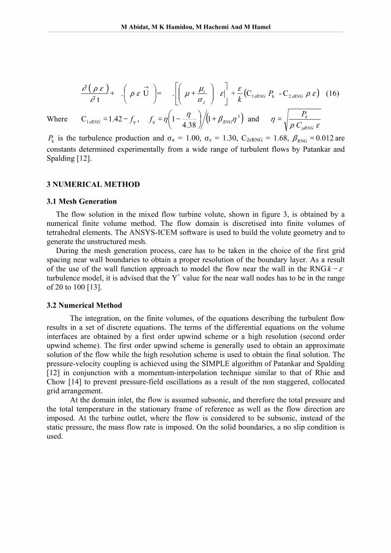
4.1 – Grid solution dependency For both volutes, the grid influence on the solution was studied. For each case, three mesh sizes have been used to compute the turbulent flow solution in the turbine volute in order to choose the optimal grid for the final computation. The solutions obtained with the three grids are presented in figures 04 in terms of static pressure distribution along the mean streamline which starts from the volute inlet centre. The grids II with 395523 and 248293 elements for the radial inflow turbine volute [8] and the mixed flow turbine volute respectively were found to give a satisfactory solution and were used for the numerical tests.
0.06 0.08 0.10 0.12 0.14 0.16
0
200
400
600
800
1000
1200
1400
1600
1800
Mean stream line pressure distribution:Grid solution independency
Rel
ativ
e St
atic
Pre
ssur
e (P
a)
Radius (m)
Number of Elements 269595 (Grid I) 395233 (Grid II) 787423 (Grid III)
0.045 0.050 0.055 0.060 0.065 0.070 0.075 0.080 0.085106000
106500
107000
107500
108000
108500
109000 Inlet Total Pressure = 1,239 (bar)Mass Flow Rate = 0.1822 (kg s^-1)Inlet Total Temperature = 340 (K)
Stat
ic P
ress
ure
(Pa)
Rradial distance (m)
Grid Size 153832 (Grid I) 248293 (Grid II) 799867 (Grid III)
a) Radial Inflow turbine volute b) Mixed flow turbine volute Figure 04: Grid solution independency
0.0 0.2 0.4 0.6 0.8 1.0
-1.0
-0.5
0.0
0.5
1.0
1.5
2.0
2.5
3.0
3.5
4.0
4.5
ShroudHub
Volute outlet axial distribution of radial velocity
V r / V
r
z/be
CFX Exp[8] bs/be 1.5 1.9 2.8 3.7
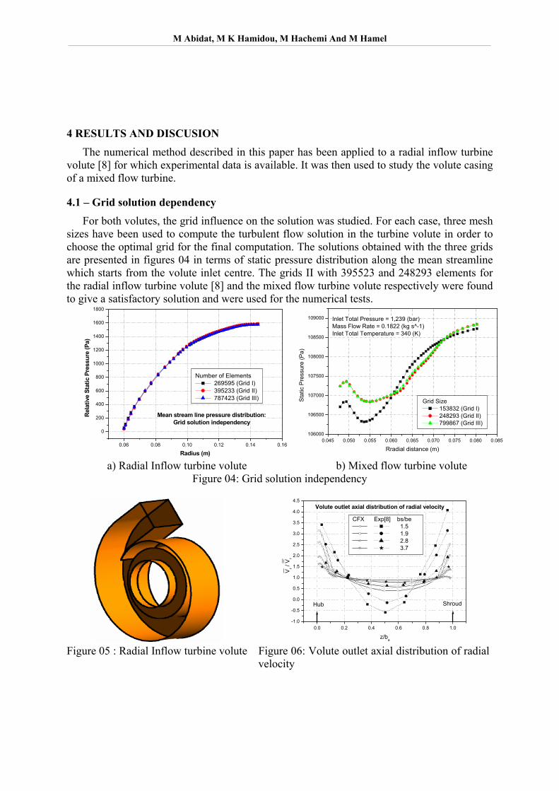
Figure 05 : Radial Inflow turbine volute Figure 06: Volute outlet axial distribution of radial
velocity
M Abidat, M K Hamidou, M Hachemi And M Hamel
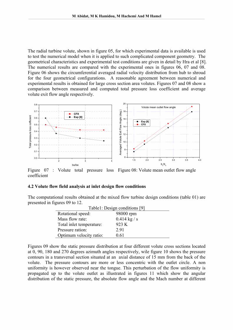
The radial turbine volute, shown in figure 05, for which experimental data is available is used to test the numerical model when it is applied to such complicated component geometry. The geometrical characteristics and experimental test conditions are given in detail by Hra et al [8]. The numerical results are compared with the experimental ones in figures 06, 07 and 08. Figure 06 shows the circumferential averaged radial velocity distribution from hub to shroud for the four geometrical configurations. A reasonable agreement between numerical and experimental results is obtained for large cross section area volutes. Figures 07 and 08 show a comparison between measured and computed total pressure loss coefficient and average volute exit flow angle respectively.
2 3 40.0
0.1
0.2
0.3
0.4
0.5
0.6
0.7
0.8
Tota
l pre
ssur
e lo
ss c
offic
ient
CFX Exp [8]
bs/be 1.5 2.0 2.5 3.0 3.5 4.0
6
8
10
12
14
16
18
20
Volute mean outlet flow angle
Aver
aged
Vol
ute
Exi
t Flo
w A
ngle
(deg
.)
bs/be
Exp [8] CFX
Figure 07 : Volute total pressure loss coefficient
Figure 08: Volute mean outlet flow angle
4.2 Volute flow field analysis at inlet design flow conditions The computational results obtained at the mixed flow turbine design conditions (table 01) are presented in figures 09 to 12.
Table1: Design conditions [9] Rotational speed: 98000 rpm Mass flow rate: 0.414 kg / s Total inlet temperature: 923 K Pressure ration: 2.91 Optimum velocity ratio: 0.61
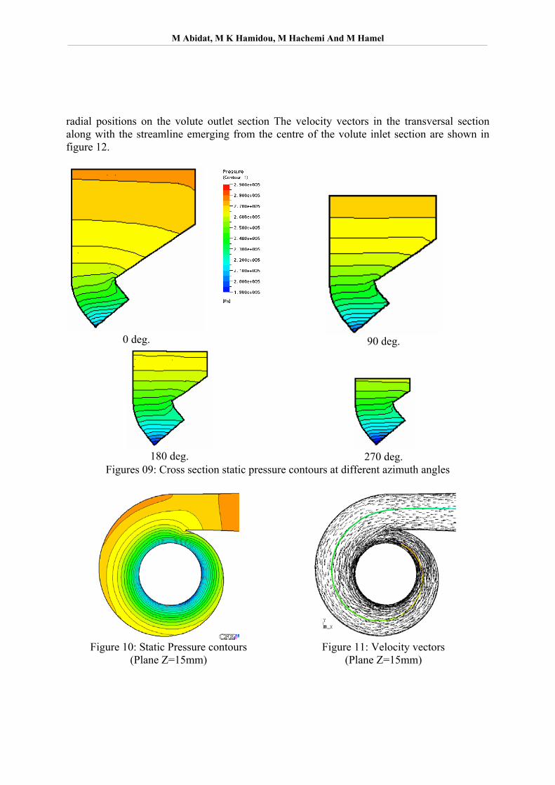
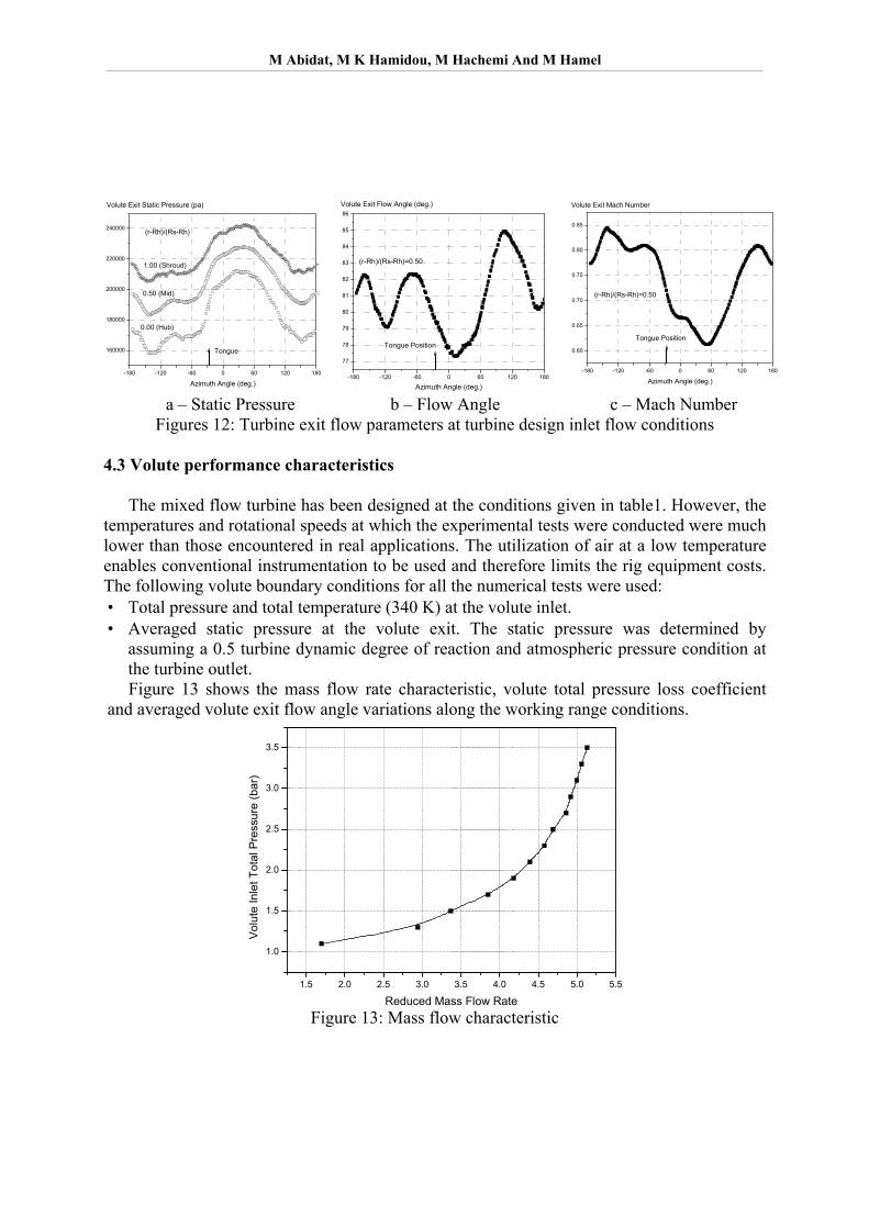
Figures 09 show the static pressure distribution at four different volute cross sections located at 0, 90, 180 and 270 degrees azimuth angles respectively, wile figure 10 shows the pressure contours in a transversal section situated at an axial distance of 15 mm from the back of the volute. The pressure contours are more or less concentric with the outlet circle. A non uniformity is however observed near the tongue. This perturbation of the flow uniformity is propagated up to the volute outlet as illustrated in figures 11 which show the angular distribution of the static pressure, the absolute flow angle and the Mach number at different
M Abidat, M K Hamidou, M Hachemi And M Hamel
radial positions on the volute outlet section The velocity vectors in the transversal section along with the streamline emerging from the centre of the volute inlet section are shown in figure 12.
0 deg.
90 deg.
180 deg.
270 deg.
Figures 09: Cross section static pressure contours at different azimuth angles
Figure 10: Static Pressure contours
(Plane Z=15mm) Figure 11: Velocity vectors
(Plane Z=15mm)
M Abidat, M K Hamidou, M Hachemi And M Hamel
-180 -120 -60 0 60 120 180
160000
180000
200000
220000
240000
Volute Exit Static Pressure (pa)
(r-Rh)/(Rs-Rh)
Tongue
0.50 (Mid)
0.00 (Hub)
1.00 (Shroud)
Azimuth Angle (deg.) -180 -120 -60 0 60 120 180
77
78
79
80
81
82
83
84
85
86Volute Exit Flow Angle (deg.)
Tongue Position
(r-Rh)/(Rs-Rh)=0.50
Azimuth Angle (deg.)
-180 -120 -60 0 60 120 180
0.60
0.65
0.70
0.75
0.80
0.85
Volute Exit Mach Number
Tongue Position
(r-Rh)/(Rs-Rh)=0.50
Azimuth Angle (deg.)
a – Static Pressure b – Flow Angle c – Mach Number Figures 12: Turbine exit flow parameters at turbine design inlet flow conditions
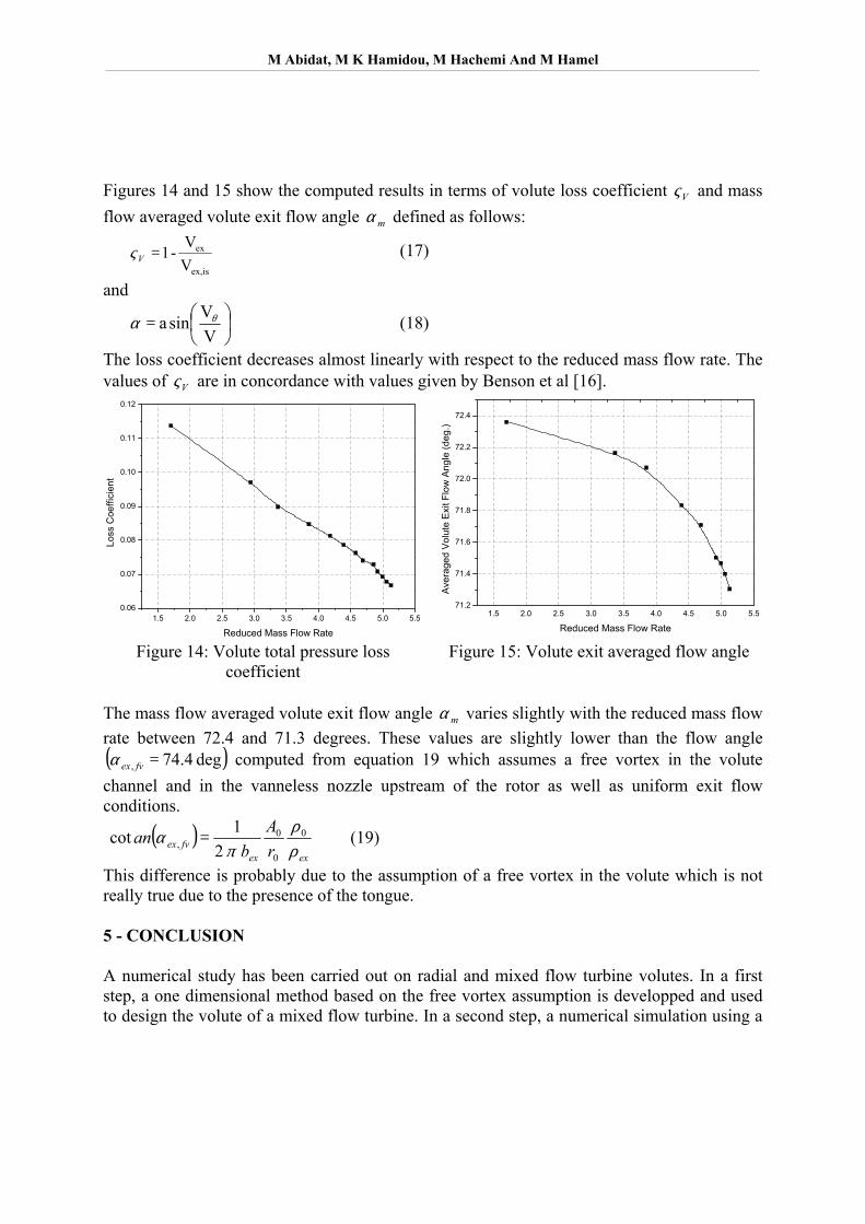
4.3 Volute performance characteristics The mixed flow turbine has been designed at the conditions given in table1. However, the temperatures and rotational speeds at which the experimental tests were conducted were much lower than those encountered in real applications. The utilization of air at a low temperature enables conventional instrumentation to be used and therefore limits the rig equipment costs. The following volute boundary conditions for all the numerical tests were used: • Total pressure and total temperature (340 K) at the volute inlet. • Averaged static pressure at the volute exit. The static pressure was determined by
assuming a 0.5 turbine dynamic degree of reaction and atmospheric pressure condition at the turbine outlet.
Figure 13 shows the mass flow rate characteristic, volute total pressure loss coefficient and averaged volute exit flow angle variations along the working range conditions.
1.5 2.0 2.5 3.0 3.5 4.0 4.5 5.0 5.5
1.0
1.5
2.0
2.5
3.0
3.5
Volu
te In
let T
otal
Pre
ssur
e (b
ar)
Reduced Mass Flow Rate Figure 13: Mass flow characteristic
M Abidat, M K Hamidou, M Hachemi And M Hamel
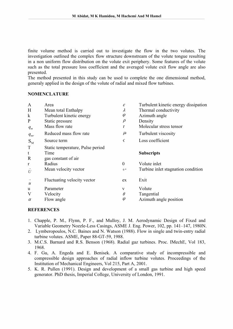
Figures 14 and 15 show the computed results in terms of volute loss coefficient Vς and mass flow averaged volute exit flow angle mα defined as follows:
isex,
ex
VV
-1 =Vς (17)
and
=
VVsina θα (18)
The loss coefficient decreases almost linearly with respect to the reduced mass flow rate. The values of Vς are in concordance with values given by Benson et al [16].
1.5 2.0 2.5 3.0 3.5 4.0 4.5 5.0 5.50.06
0.07
0.08
0.09
0.10
0.11
0.12
Loss
Coe
ffici
ent
Reduced Mass Flow Rate
1.5 2.0 2.5 3.0 3.5 4.0 4.5 5.0 5.571.2
71.4
71.6
71.8
72.0
72.2
72.4
Ave
rage
d V
olut
e E
xit F
low
Ang
le (d
eg.)
Reduced Mass Flow Rate
Figure 14: Volute total pressure loss coefficient
Figure 15: Volute exit averaged flow angle
The mass flow averaged volute exit flow angle mα varies slightly with the reduced mass flow rate between 72.4 and 71.3 degrees. These values are slightly lower than the flow angle ( )deg 4.74, =fvexα computed from equation 19 which assumes a free vortex in the volute channel and in the vanneless nozzle upstream of the rotor as well as uniform exit flow conditions.
( )exex
fvex rA
ban
ρρ
πα 0
0
0, 2
1cot = (19)
This difference is probably due to the assumption of a free vortex in the volute which is not really true due to the presence of the tongue. 5 - CONCLUSION A numerical study has been carried out on radial and mixed flow turbine volutes. In a first step, a one dimensional method based on the free vortex assumption is developped and used to design the volute of a mixed flow turbine. In a second step, a numerical simulation using a
M Abidat, M K Hamidou, M Hachemi And M Hamel
finite volume method is carried out to investigate the flow in the two volutes. The investigation outlined the complex flow structure downstream of the volute tongue resulting in a non uniform flow distribution on the volute exit periphery. Some features of the volute such as the total pressure loss coefficient and the averaged volute exit flow angle are also presented. The method presented in this study can be used to complete the one dimensional method, generaly applied in the design of the volute of radial and mixed flow turbines. NOMENCLATURE A Area ε Turbulent kinetic energy dissipation H Mean total Enthalpy λ Thermal conductivity k Turbulent kinetic energy ψ Azimuth angle P Static pressure ρ Density
mq Mass flow rate τ Molecular stress tensor
mrq Reduced mass flow rate tµ Turbulent viscosity
MS Source term ς Loss coefficient T Static temperature, Pulse period t Time Subscripts R gas constant of air r Radius 0 Volute inlet →U Mean velocity vector *0 Turbine inlet stagnation condition
→u
Fluctuating velocity vector ex Exit
u Parameter v Volute V Velocity θ Tangential α Flow angle ψ Azimuth angle position REFERENCES 1. Chapple, P. M., Flynn, P. F., and Mulloy, J. M. Aerodynamic Design of Fixed and
Variable Geometry Nozzle-Less Casings, ASME J. Eng. Power, 102, pp. 141–147, 1980N. 2. Lymberopoulos, N.C. Baines and N. Watson (1988). Flow in single and twin-entry radial
turbine volutes. ASME, Paper 88-GT-59, 1988. 3. M.C.S. Barnard and R.S. Benson (1968). Radial gaz turbines. Proc. IMechE, Vol 183,
1968. 4. F. Gu, A. Engeda and E. Benisek. A comparative study of incompressible and
compressible design approaches of radial inflow turbine volutes. Proceedings of the Institution of Mechanical Engineers, Vol 215, Part A, 2001.
5. K. R. Pullen (1991). Design and development of a small gas turbine and high speed generator. PhD thesis, Imperial College, University of London, 1991.

M Abidat, M K Hamidou, M Hachemi And M Hamel
6. L. F. Ellison and J. M. Partridge (1978). Vane vibration in radial flow turbochargers. In turbocharging and turbochargers. IME, 1978.
7. M. Abidat and M. Hachemi (2005). Off design performance analyses of a turbocharger mixed flow turbine. 6th European Turbomachinery Conference, Lille, Mars 2005
8. K. Hara, M. Furukawa and M. Inoue (1994). Behavior of Three-Dimensional Boundary Layers in a Radial Inflow Turbine Scroll. Journal of Turbomachinery, Tarnsaction of the ASME, vol. 116, July 1004, pp. 446-452.
9. M. Abidat, H. Chen, N. C. Baines and M. R. Firth (1992). Design of a Highly Loaded Mixed Flow Turbine Proc I Mech E, Journ. Power and Energy, 1992, Vol 206.
10. A. R. Forest (1972). Interactive interpolation and approximation by Bezier polynomials. Computer J. 1072, 15, 71-79.
11. M. V. Casey (1983). A computational geometry for the blades and internal flow channels of centrifugal compressors. Trans. ASME, J. Engng for Power, 1089, 105, 288-295.
12. Patankar S. V. and Spalding D. B. (1972). A calculation procedure for heat, mass and momentum transfer in three-dimensional parabolic flows. Int. J. of Heat and Mass Transfer, vol.15, pp. 1778-1806, 1972.
13. Turbulence and Near-Wall modelling, ANSYS CFX 5.7, 2005. 14. Rhie, C. M. and Chow, W. L. A., (1982). Numerical Study of the Turbulent Flow Past an
Isolated Airfoil with Trailing Edge Separation, AIAA Paper 82-0998, 1982 15. H. Chen, M. Abidat, N.C. Baines & M.R. Firth (1992). The Effect of Blade Loading in
Radial and Mixed Flow Turbines. ASME 1992, Paper No 92-GT-92 16. R. S. Benson, W. G. Cartwright and S. K. Das (1068). An investigation of the losses in the
rotor of a radial flow gas turbine at zero incidence under conditions of steady flow. I Mech E, Thermodynamics and Fluid Mechanics Convention. Bristol, 27-20 March 1968, Paper 23.